

Page 1
G9849
10
20
30
40
50
60
70
80
90
0
0
.5
.4
.9
.3
.8
.2
.7
.1
.6
.001'' 0—1''
20
10
90
80
70
60
50
40
30
0
ON
OFF
Magnetic Base/Dial
Indicator Combo
The Model G9849 Magnetic Base/Dial Indicator Combo features a 0.001" resolution, 1" range, and a 2"
easy-to-read dial. The indicator is supplied with a decade counter, adjustable markers and a dial face lock.
The magnetic base features an ON/OFF switch, a magnetic base for both tubular and flat mounting, a stout
column, fine-tune adjustment knob and 2 positioning joints. This tool will allow you to accurately and quickly
measure runout, lead, and motion. Please familiarize yourself with the terminology of the components to
maximize the effective use of this tool.
2
1
3
6
4
5
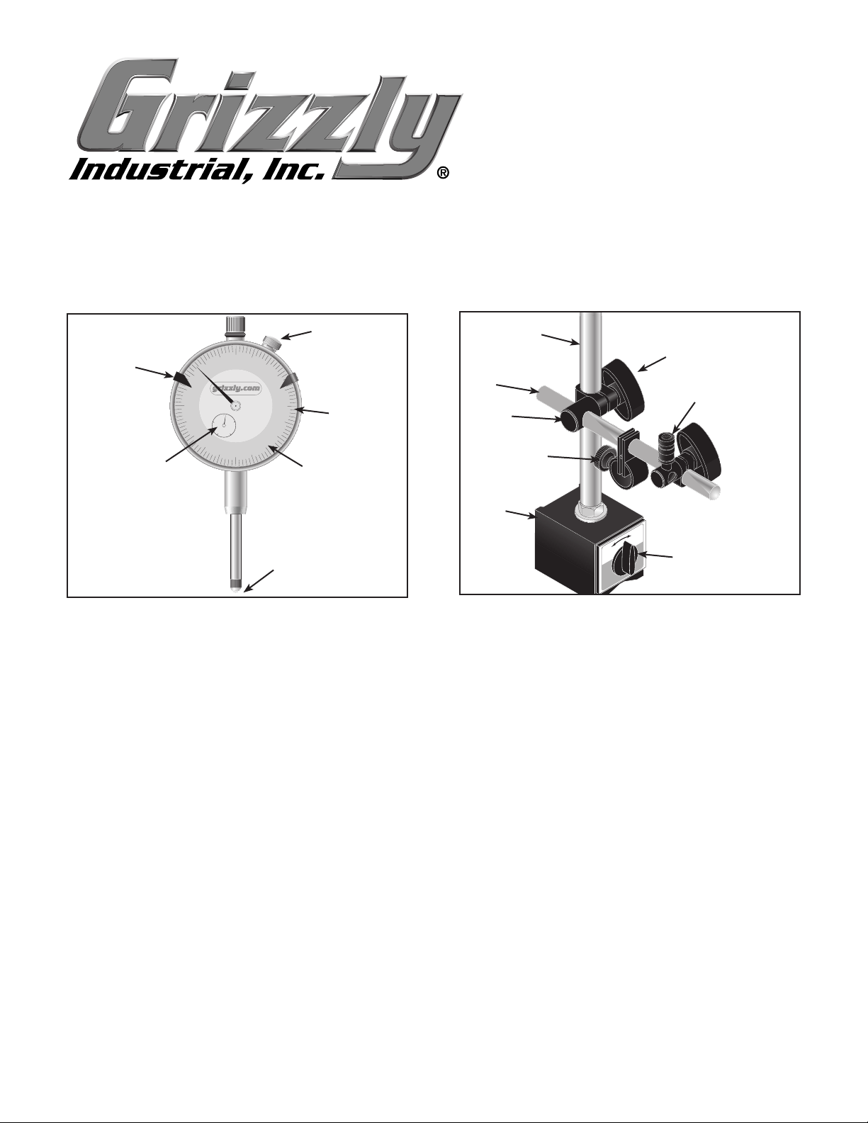
Figure 1. Indicator components.
Listed below are the dial indicator components.
Match the description with the corresponding part
number in the illustration above.
1. The adjustable markers can be moved along
the circumference of the dial.
2. The dial lock secures the dial face after being
rotated around the indicator body.
3. On the scale, the distance between the lines
equals 0.001" (one thousandths of an inch).
4. These numbers represent 0.010" (ten thou-
sandths of an inch).
5. The contact point touches the surface to be
measured.
6. Each number on the decade counter repre-
sents one full rotation of the needle and is
equal to 0.100" (one hundred thousandths of
an inch).
-1-
1
2
8
3
7
6
5
4
Figure 2. Magnetic base components.
Below is a list of the magnetic base components.
1. The column supports the mounting assem-
bly.
2. The lock knobs secure the mounting assem-
bly after adjustments are made.
3. The indicator mounting stud fastens indicator
to the boom.
4. The ON/OFF switch for the magnet.
5. The magnetic base. One mounting surface
on the back and one on the bottom.
6. The fine-tune adjustment knob allows the
indicator to be adjusted in small increments.
7. One of 2 pivot joints that allows articulation of
the mounting assembly.
8. The boom supports the mounting assembly.
© 2002 Grizzly Industrial, Inc.
Page 2
Dial IndicatorMagnetic Base
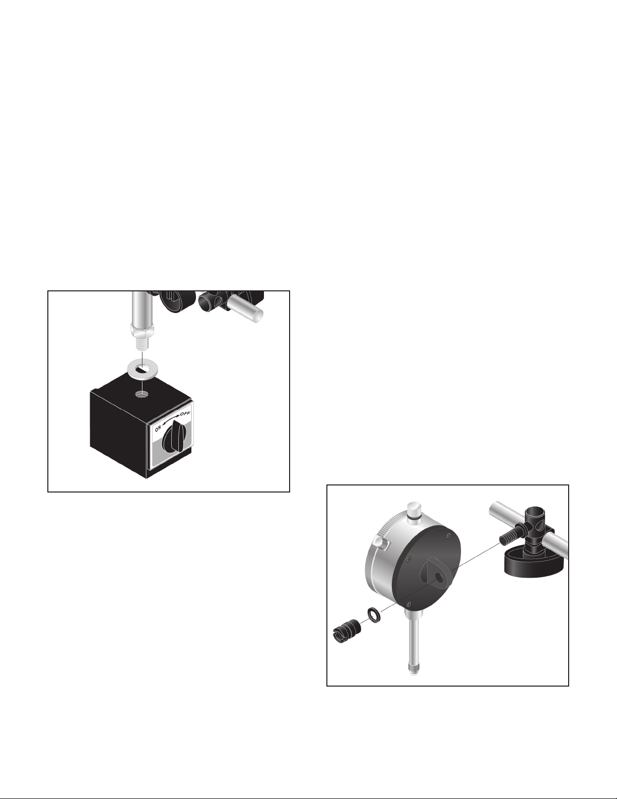
The magnetic base supports the column and the
mounting assembly. To assemble the column to
the base:
1. Locate the flat washer in the package containing the column/mounting assembly and
attach the washer to the threaded end of the
column.
2. Thread the column into the threaded hole
on the top of the magnetic base until it stops
turning.
3. Finish tightening the column by turning the
jam nut with an
11
⁄16" wrench.
The indicator must be secured to the base prior to
use. Please refer to Figure 4 while reading these
instructions.
1. Loosen the lock knob that secures the
mounting stud to the boom and remove the
stud.
2. Unscrew and remove the knurled nut and flat
washer from the mounting stud, and insert
the threaded end of the stud into the flange
on the back of the dial indicator.
The stud can be inserted from the left- or the
right-hand side, depending on your mounting
needs.
3. Attach the washer and thread the knurled nut
back onto the threads on the stud. Insert the
plain end of the stud into the pivot joint. Be
mindful that this pivot joint has 2 holes and
only one is sized correctly for the stud. Also,
it may be necessary to rotate the sleeve on
the pivot joint to correctly align the parts so
the stud can be inserted.
Figure 3. Mounting the column.
4. Tighten the lock knob for the pivot joint.
5. Tighten the knurled nut with a flat blade
screwdriver to lock the dial into place.
Figure 4. Mounting the indicator onto the
mounting stud.
-2-
© 2002 Grizzly Industrial, Inc.462402622
Page 3
Basic Operations
10
20
30
40
50
60
70
80
90
0
0
.5
.4
.9
.3
.8
.2
.7
.1
.6
.001' ' 0—1''
20
10
90
80
70
60
50
40
30
0
90˚
Adjusting the Assembly
The dial indicator can be used in many ways and
the magnetic base can be positioned on flat or
round surfaces. The list below detail guidelines
for use:
1. Use the ON/OFF switch on the magnetic
base whenever moving the unit to help avoid
marring the surface that it is resting on and to
prevent sudden jarring which could damage
the internal components of the indicator.
2. Make adjustments to the support assembly
only with the base magnetically secured to
a steel or iron object. This will help guard
against damage to the indicator should the
base fall.
3. Loosen the lock knobs to adjust the height
and angle of the support boom. Trying to
defeat the locks to move the indicator a small
amount will cause premature wear on the
system.
The magnetic base and indicator can be positioned in many ways. The bottom of the magnetic
base is notched to allow for mounting to curved
surfaces as well as having a ground, flat surface.
The back of the base is ground flat for mounting
as well. Care must be taken to secure the base
to a suitable surface. Hanging the base upsidedown or from the side of a machine may cause
the unit to fall. Also, sheet metal may not have the
mass need to properly support the unit. Dropping
the dial indicator will reduce its accuracy and may
make it unusable.
4. Gently, try to rock the base after turning the
switch to the ON position to ensure that the
setup is secure.
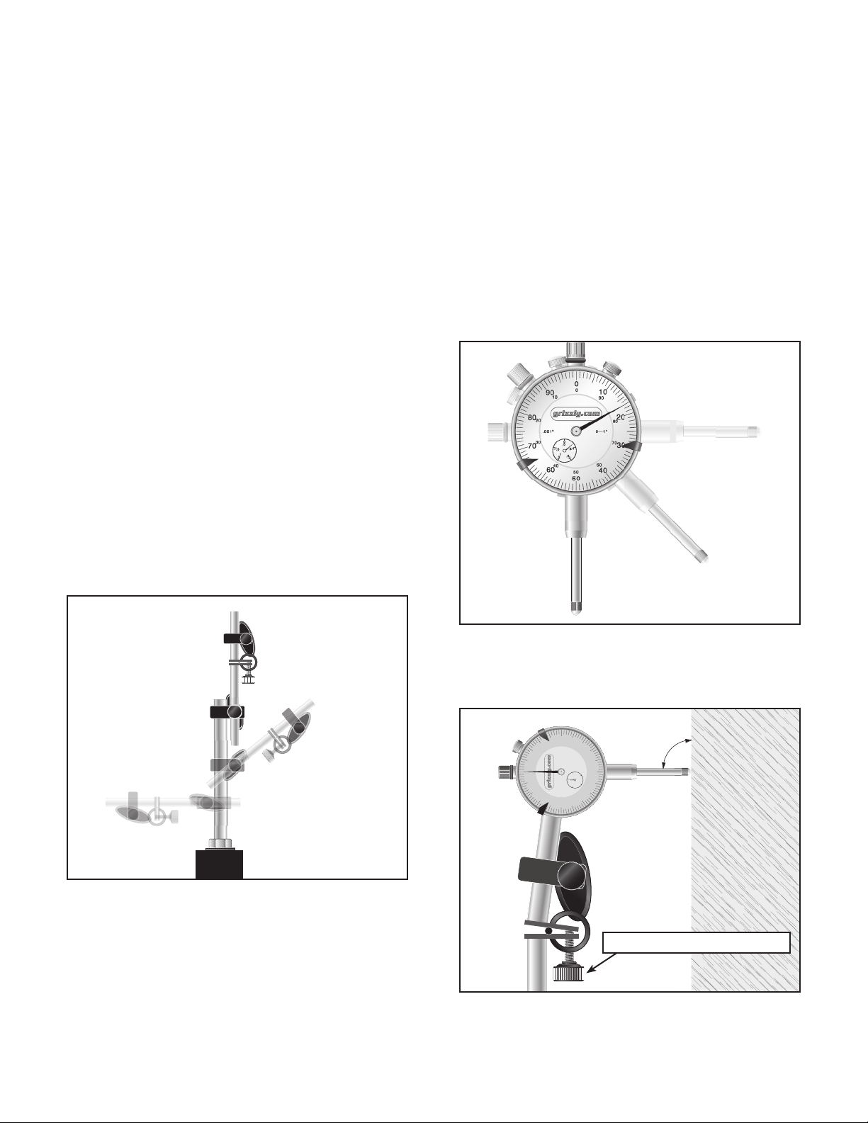
Figure 5. The support assembly can be positioned in any fashion by loosening the 2 pivot
joints.
Figure 6. The indicator can be oriented in any
direction by loosening the mounting stud, loos-
ening the boom and raising the boom along the
column.
fine-tune adjustment knob
-3-
462402622
Figure 7. Fine tuning the dial to read zero or
any other reference point is made easy with the
fine-tune adjustment knob.
© 2002 Grizzly Industrial, Inc.
Page 4
Setting the Contact Point
10
20
30
40
50
60
70
80
90
0
0
.5
.4
.9
.3
.8
.2
.7
.1
.6
.001'' 0—1''
20
10
90
80
70
60
50
40
30
0
10
20
30
40
50
60
70
80
90
0
0
.5
.4
.9
.3
.8
.2
.7
.1
.6
.001'' 0—1''
20
10
90
80
70
60
50
40
30
0
C
L
90˚
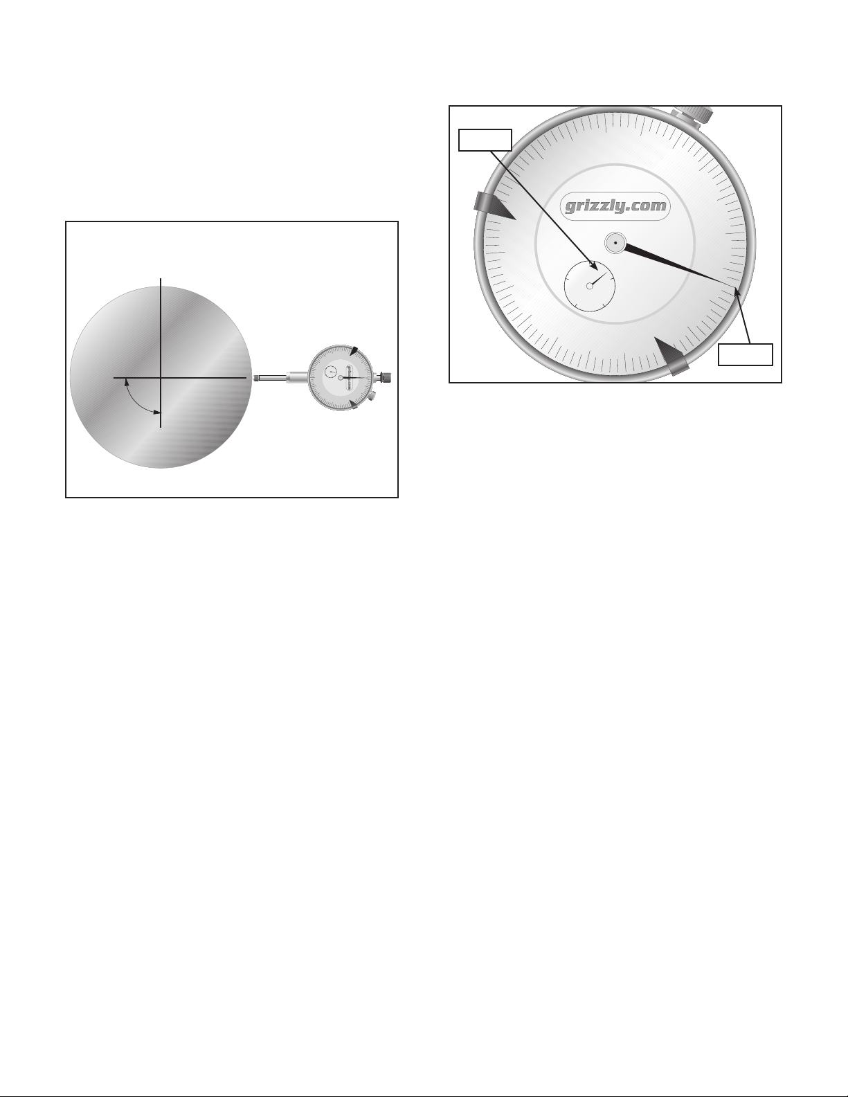
One of the most important setup issues with a
dial indicator is to make sure the contact point
is perpendicular to its expected motion or to
the motion of the object to be tested. Failure to
ensure proper setup will result in an error in measurement. Please refer to Figure 7 and 8.
Reading the Dial
0.400"
0.017"
Figure 9. The dial reads 0.417".
The dial indicator is calibrated to read 0.001" and
has a range of 1". When the contact point is not
touching anything, the pointers for each dial will
read “under” the zero inch mark.
Figure 8. The indicator is positioned perpendic-
ular to the axis of a round bar. When the bar is
turned, the runout or lateral motion is indicated
by motion of the needle.
Another important note about setup is that the
contact point must be resting against the part
before any change can be indicated. It is therefore necessary to adjust the unit so the needle
has moved to ensure a proper measurement.
Use the fine-tune adjustment knob illustrated in
Figure 7.
Dial Lock
Loosening the dial lock allows the dial face to
be rotated. This can be helpful when an absolute
measurement is desired and changing the adjustments to the column, boom and fine adjustment
knob are difficult or impractical. In Figure 9 the
dial face has been rotated.
-4-
It is important to understand that the pointers
rotate in opposite directions as the contact point
is depressed. The pointer for the large dial rotates
clockwise and the pointer for the smaller dial
rotates counterclockwise when the contact point
is depressed. You must keep track of the number
of revolutions for the smaller dial! The first revolution is indicated by the numbers on the outer ring
of the numbers and the second revolution is indicated by the innermost numbers. The example in
Figure 9 indicates 0.417".
As with the decade counter, the main dial has
a second set of numbers. These can be used
to keep track of the actual motion of the contact
point when it is released.
The dial indicator can also be set up to be used
as a range tester. There are 2 adjustable mark-
ers that can be positioned on the dial face. A
range can then be checked. In the example in
Figure 9, the adjustable markers have been set
to measure between 0.030" and 0.065". Again, if
a larger range than 0.100" is needed, the revolutions of the pointer on the smaller dial will have
to be counted.
462402622
Adjustable Markers
© 2002 Grizzly Industrial, Inc.
 Loading...