

Page 1

MODEL G9742
5"x 6" METAL-CUTTING
BANDSAW w/ SWIVEL HEAD
OWNER'S MANUAL
(For models manufactured since 11/06)
COPYRIGHT © NOVEMBER, 2005 BY GRIZZLY INDUSTRIAL, INC. REVISED FEBRUARY, 2013 (TS)
WARNING: NO PORTION OF THIS MANUAL MAY BE REPRODUCED IN ANY SHAPE
OR FORM WITHOUT THE WRITTEN APPROVAL OF GRIZZLY INDUSTRIAL, INC.
#PC7670 PRINTED IN CHINA
Page 2

This manual provides critical safety instructions on the proper setup,
operation, maintenance, and service of this machine/tool. Save this
document, refer to it often, and use it to instruct other operators.
Failure to read, understand and follow the instructions in this manual
may result in fire or serious personal injury—including amputation,
electrocution, or death.
The owner of this machine/tool is solely responsible for its safe use.
This responsibility includes but is not limited to proper installation in
a safe environment, personnel training and usage authorization,
proper inspection and maintenance, manual availability and comprehension, application of safety devices, cutting/sanding/grinding tool
integrity, and the usage of personal protective equipment.
The manufacturer will not be held liable for injury or property damage
from negligence, improper training, machine modifications or misuse.
Some dust created by power sanding, sawing, grinding, drilling, and
other construction activities contains chemicals known to the State
of California to cause cancer, birth defects or other reproductive
harm. Some examples of these chemicals are:
• Lead from lead-based paints.
• Crystalline silica from bricks, cement and other masonry products.
• Arsenic and chromium from chemically-treated lumber.
Your risk from these exposures varies, depending on how often you
do this type of work. To reduce your exposure to these chemicals:
Work in a well ventilated area, and work with approved safety equipment, such as those dust masks that are specially designed to filter
out microscopic particles.
Page 3

Table of Contents
INTRODUCTION ............................................... 2
Foreword ........................................................ 2
Contact Info.................................................... 2
Machine Data Sheet ...................................... 3
Identification ................................................... 5
SECTION 1: SAFETY ....................................... 6
Safety Instructions for Machinery .................. 6
Additional Safety Instructions for Metal Cutting
Bandsaws ...................................................... 8
SECTION 2: CIRCUIT REQUIREMENTS ........ 9
110/220V Operation ....................................... 9
SECTION 3: SET UP ...................................... 10
Set Up Safety ............................................... 10
Items Needed for Set Up ............................. 10
Unpacking .................................................... 10
Inventory ...................................................... 11
Clean Up ...................................................... 12
Site Considerations ...................................... 12
Cabinet, Wheels & Feet ............................... 13
Squaring Vise to Blade ................................ 15
Chip Tray & Cast Iron Stop.......................... 16
OFF Button Lever ........................................ 16
Pulley Cover................................................. 17
Test Run ...................................................... 18
Recommended Adjustments ........................ 18
SECTION 4: OPERATIONS ........................... 19
Operation Safety .......................................... 19
Blade Speed ................................................ 19
Blade Selection ............................................ 20
Feed Rate .................................................... 21
Blade Guides ............................................... 22
Blade Tension .............................................. 23
Operation Tips ............................................. 23
SECTION 5: ACCESSORIES ......................... 24
SECTION 6: MAINTENANCE ......................... 26
Schedule ...................................................... 26
Cleaning ....................................................... 26
Lubrication ................................................... 26
SECTION 7: SERVICE ................................... 27
Troubleshooting ........................................... 27
Blade Change .............................................. 29
Blade Tracking ............................................. 30
Electrical Components ................................. 31
G9742 Wiring Diagram ................................ 32
Saw Parts Breakdown ................................. 33
Stand Parts Breakdown ............................... 35
Guides & Shafts Parts Breakdown .............. 37
Labels Parts Breakdown .............................. 38
WARRANTY AND RETURNS ........................ 41
Page 4

INTRODUCTION
Foreword
We are proud to offer the Model G9742 5" x 6"
Metal-Cutting Bandsaw with Swivel Head. This
machine is part of a growing Grizzly family of fine
metalworking machinery. When used according
to the guidelines set forth in this manual, you can
expect years of trouble-free, enjoyable operation
and proof of Grizzly’s commitment to customer
satisfaction.
We are pleased to provide this manual with
the Model G9742. It was written to guide you
through assembly, review safety considerations,
and cover general operating procedures. It represents our effort to produce the best documentation possible.
The specifications, drawings, and photographs
illustrated in this manual represent the Model
G9742 as supplied when the manual was prepared. However, owing to Grizzly’s policy of continuous improvement, changes may be made at
any time with no obligation on the part of Grizzly.
For your convenience, we always keep current
Grizzly manuals available on our website at www.
grizzly.com. Any updates to your machine will be
reflected in these manuals as soon as they are
complete. Visit our site often to check for the latest updates to this manual!
Contact Info
If you have any comments regarding this manual,
please write to us at the address below:
C
/O Technical Documentation Manager
We stand behind our machines. If you have any
service questions or parts requests, please call or
write us at the location listed below.
Grizzly Industrial, Inc.
P.O. Box 2069
Bellingham, WA 98227-2069
Grizzly Industrial, Inc.
1203 Lycoming Mall Circle
Muncy, PA 17756
Phone: (570) 546-9663
Fax: (800) 438-5901
E-Mail: techsupport@grizzly.com
Web Site: http://www.grizzly.com
-2-
G9742 Metal Cutting Bandsaw (Mfg. Since 11/06
Page 5

MACHINE DATA
SHEET
Customer Service #: (570) 546-9663 · To Order Call: (800) 523-4777 · Fax #: (800) 438-5901
MODEL G9742 5" X 6" METAL-CUTTING BANDSAW W/
SWIVEL HEAD
Product Dimensions:
Weight.............................................................................................................................................................. 150 lbs.
Width (side-to-side) x Depth (front-to-back) x Height............................................................... 39 x 23-3/8 x 54-3/4 in.
Footprint (Length x Width)............................................................................................................... 26-1/2 x 20-1/2 in.
Shipping Dimensions:
Type................................................................................................................................................... Wood Slat Crate
Content........................................................................................................................................................... Machine
Weight.............................................................................................................................................................. 168 lbs.
Length x Width x Height....................................................................................................................... 41 x 18 x 22 in.
Must Ship Upright................................................................................................................................................... Yes
Electrical:
Power Requirement............................................................................................. 110V or 220V, Single-Phase, 60 Hz
Prewired Voltage.................................................................................................................................................. 110V
Full-Load Current Rating...................................................................................................... 7A at 110V, 3.5A at 220V
Minimum Circuit Size.......................................................................................................... 15A at 110V, 15A at 220V
Switch...................................................................................................... Sealed Button Switch w/Automatic Shut-Off
Cord Length............................................................................................................................................................ 6 ft.
Cord Gauge.................................................................................................................................................... 18 AWG
Plug Included.......................................................................................................................................................... Yes
Motors:
Main
Type................................................................................................................. TEFC Capacitor-Start Induction
Horsepower............................................................................................................................................. 1/2 HP
Phase............................................................................................................................................ Single-Phase
Amps...................................................................................................................................................... 7A/3.5A
Speed................................................................................................................................................ 1725 RPM
Power Transfer ............................................................................................................................... V-Belt Drive
Bearings..................................................................................................... Shielded & Permanently Lubricated
Main Specifications:
Operation Info
Blade Speeds......................................................................................................................... 80, 120, 200 FPM
Std. Blade Length................................................................................................................................ 64-1/2 in.
Blade Size Range..................................................................................................................................... 1/2 in.
Head Swivel............................................................................................................................................ 45 deg.
Machine Data Sheet
G9742 Metal Cutting Bandsaw (Mfg. Since 11/06
-3-
Page 6

Cutting Capacities
Angle Cuts........................................................................................................................ Right 45, Left 60 deg.
Vise Jaw Depth...................................................................................................................................... 4-3/8 in.
Vise Jaw Height..................................................................................................................................... 2-1/2 in.
Max. Capacity Rectangular Height at 90 Deg.............................................................................................. 5 in.
Max. Capacity Rectangular Width at 90 Deg............................................................................................... 6 in.
Max. Capacity Round at 90 Deg.................................................................................................................. 5 in.
Max. Capacity Rectangular Height at 30 Deg.............................................................................................. 5 in.
Max. Capacity Rectangular Width at 30 Deg............................................................................................... 5 in.
Max. Capacity Round at 30 Deg.................................................................................................................. 5 in.
Max. Capacity Rectangular Height at 45 Deg................................................................................... 2-15/16 in.
Max. Capacity Rectangular Width at 45 Deg......................................................................................... 3-3/4 in.
Max. Capacity Round at 45 Deg............................................................................................................ 3-3/4 in.
Max. Capacity Rectangular Height at 60 Deg....................................................................................... 1-3/4 in.
Max. Capacity Rectangular Width at 60 Deg....................................................................................... 2-3/16 in.
Max. Capacity Round at 60 Deg............................................................................................................ 1-3/4 in.
Construction
Table....................................................................................................................... Precision Ground Cast Iron
Upper Wheel....................................................................................................................... Machined Cast Iron
Lower Wheel....................................................................................................................... Machined Cast Iron
Body..................................................................................................................................................... Cast Iron
Base.......................................................................................... Formed and Welded Steel with Coolant Sump
Wheel Cover............................................................................................................................ Pre-formed Steel
Paint......................................................................................................................................................... Epoxy
Other
Wheel Size................................................................................................................................................. 13 in.
Blade Guides Upper........................................................................................................................ Ball Bearing
Blade Guides Lower........................................................................................................................ Ball Bearing
Table Info
Table Size Length...................................................................................................................................... 12 in.
Table Size Width................................................................................................................................... 4-1/2 in.
Floor To Cutting Area Height..................................................................................................................... 29 in.
Other Specifications:
ISO 9001 Factory .................................................................................................................................................. Yes
Country Of Origin ............................................................................................................................................... China
Warranty ........................................................................................................................................................... 1 Year
Serial Number Location ........................................................................................................ ID Label on Body Frame
Approximate Assembly & Setup Time ........................................................................................................ 30 Minutes
Features:
Control Panel Conveniently Located
Adjustable Hydraulic Downfeed
Quick Release Vise for Rapid Change out of Workpiece
Blade Included
-4-
G9742 Metal Cutting Bandsaw (Mfg. Since 11/06
Page 7
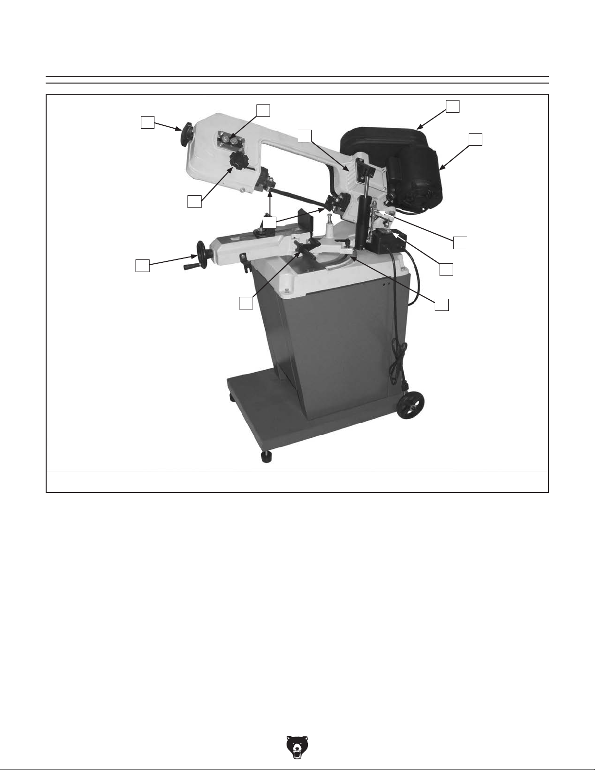
Identification
L
A
K
B
C
J
I
D
E
F
G
H
Figure 1. The Model G9742.
A. Blade Tension Knob
B. Blade Guide Knob
C. Blade Guides
D. Pulley Cover
E. Heavy Duty Motor
F. Hydraulic Cylinder and Feed Rate Dial
G. ON/OFF Push-Button Switch Assembly
H. Table Angle Scale
I. Cast Iron Stop
J. Vise Clamp Handwheel
K. Gear Box
L. Blade Tension Gauge
G9742 Metal Cutting Bandsaw (Mfg. Since 11/06
-5-
Page 8
SECTION 1: SAFETY
For Your Own Safety, Read Instruction
Manual Before Operating this Machine
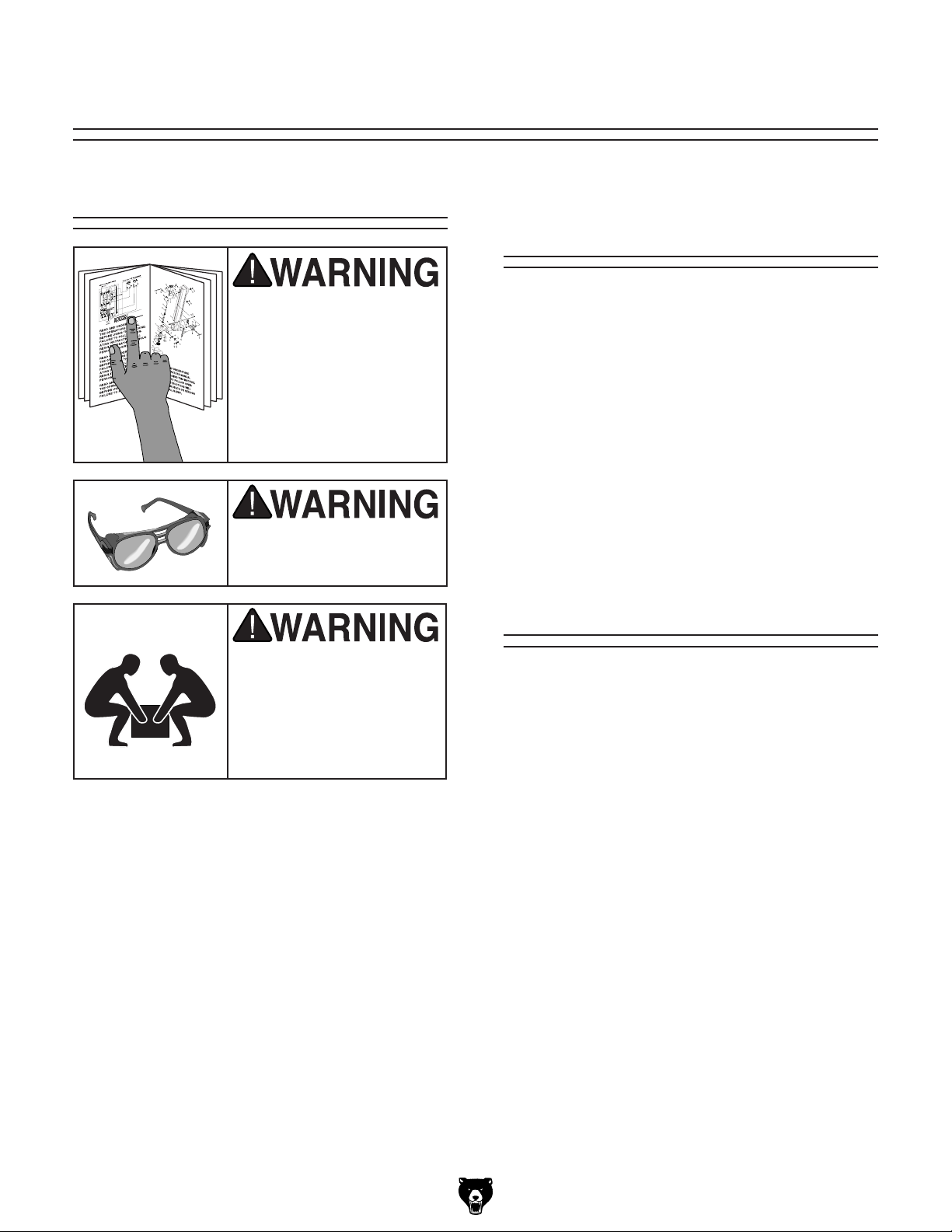
The purpose of safety symbols is to attract your attention to possible hazardous conditions. This
manual uses a series of symbols and signal words intended to convey the level of importance
of the safety messages. The progression of symbols is described below. Remember that safety
messages by themselves do not eliminate danger and are not a substitute for proper accident
prevention measures.
Indicates an imminently hazardous situation which, if not avoided,
WILL result in death or serious injury.
Indicates a potentially hazardous situation which, if not avoided,
COULD result in death or serious injury.
Indicates a potentially hazardous situation which, if not avoided,
MAY result in minor or moderate injury. It may also be used to alert
against unsafe practices.
This symbol is used to alert the user to useful information about
NOTICE
proper operation of the machine.
Safety Instructions for Machinery
Safety Instructions for Machinery
OWNER’S MANUAL. Read and understand
this owner’s manual BEFORE using machine.
Untrained users can be seriously hurt.
EYE PROTECTION. Always wear ANSIapproved safety glasses or a face shield when
operating or observing machinery. to reduce
the risk of eye injury or blindness from flying particles Everyday eyeglasses are not
approved safety glasses.
HAZARDOUS DUST. Dust created while using
machinery may cause cancer, birth defects,
or long-term respiratory damage. Be aware of
dust hazards associated with each workpiece
material, and always wear a NIOSH-approved
respirator to reduce your risk.
WEARING PROPER APPAREL. Do not wear
clothing, apparel, or jewelry that can become
entangled in moving parts. Always tie back or
cover long hair. Wear non-slip footwear to avoid
accidental slips which could cause a loss of
workpiece control.
HEARING PROTECTION. Always wear hearing protection when operating or observiing loud
machinery. Extended exposure to this noise
without hearing protection can cause permanent
hearing loss.
MENTAL ALERTNESS. Be mentally alert when
running machinery. Never operate under the
influence of drugs or alcohol, when tired, or when
distracted.
-6-
G9742 Metal Cutting Bandsaw (Mfg. Since 11/06
Page 9
SECTION 1: SAFETY
For Your Own Safety, Read Instruction
Manual Before Operating this Machine
The purpose of safety symbols is to attract your attention to possible hazardous conditions. This
manual uses a series of symbols and signal words intended to convey the level of importance
of the safety messages. The progression of symbols is described below. Remember that safety
messages by themselves do not eliminate danger and are not a substitute for proper accident
prevention measures.
Indicates an imminently hazardous situation which, if not avoided,
WILL result in death or serious injury.
Indicates a potentially hazardous situation which, if not avoided,
COULD result in death or serious injury.
Indicates a potentially hazardous situation which, if not avoided,
MAY result in minor or moderate injury. It may also be used to alert
against unsafe practices.
This symbol is used to alert the user to useful information about
NOTICE
proper operation of the machine.
Safety Instructions for Machinery
OWNER’S MANUAL. Read and understand
this owner’s manual BEFORE using machine.
Untrained users can be seriously hurt.
EYE PROTECTION. Always wear ANSIapproved safety glasses or a face shield when
operating or observing machinery. to reduce
the risk of eye injury or blindness from flying particles Everyday eyeglasses are not
approved safety glasses.
HAZARDOUS DUST. Dust created while using
machinery may cause cancer, birth defects,
or long-term respiratory damage. Be aware of
dust hazards associated with each workpiece
material, and always wear a NIOSH-approved
respirator to reduce your risk.
WEARING PROPER APPAREL. Do not wear
clothing, apparel, or jewelry that can become
entangled in moving parts. Always tie back or
cover long hair. Wear non-slip footwear to avoid
accidental slips which could cause a loss of
workpiece control.
HEARING PROTECTION. Always wear hearing protection when operating or observiing loud
machinery. Extended exposure to this noise
without hearing protection can cause permanent
hearing loss.
MENTAL ALERTNESS. Be mentally alert when
running machinery. Never operate under the
influence of drugs or alcohol, when tired, or when
distracted.
G9742 Metal Cutting Bandsaw (Mfg. Since 11/06
-7-
Page 10

Additional Safety Instructions for Metal
Cutting Bandsaws
1. BLADE CONDITION. Do not operate with
dull, cracked or badly worn blade. Inspect
blades for cracks and missing teeth before
each use.
2. HAND PLACEMENT. Never position fingers or thumbs in line with the cut. Hands
could be crushed in vise or by falling
machine components.
3. ENTANGLEMENT HAZARDS. Do not
operate this bandsaw without blade guard
in place. Otherwise, loose clothing, jewelry,
long hair and work gloves can be drawn
into working parts.
4. BLADE REPLACEMENT. When replacing
blades, make sure teeth face toward the
workpiece. Wear gloves to protect hands
and safety glasses to protect eyes.
5. WORKPIECE HANDLING. Always support
the workpiece with table, vise, or some
type of support fixture. Flag long pieces
to avoid a tripping hazard. Never hold the
workpiece with your hands during a cut.
6. LOSS OF STABILITY. Unsupported
workpieces may jeopardize machine stability and cause the machine to tip and fall
which could cause serious injury.
7. POWER INTERRUPTION. Unplug machine
after power interruption. Machines without
magnetic switches can start up after power
is restored.
8. FIRE HAZARD. Use EXTREME CAUTION
if cutting magnesium. Using the wrong cutting fluid will lead to chip fire and possible
explosion.
9. CUTTING FLUID SAFETY. Always follow
manufacturer’s cutting fluid safety instructions. Pay particular attention to contact,
contamination, inhalation, storage and disposal warnings. Spilled cutting fluid is a
slipping hazard.
10. ATTENTION TO WORK AREA. Never
leave a machine running and unattended.
Pay attention to the actions of others in the
area to avoid unintended accidents.
11. MAINTENANCE/SERVICE. All inspections, adjustments, and maintenance are
to be done with the machine OFF and the
plug pulled from the outlet. Wait for all
moving parts to come to a complete stop.
12. HEARING PROTECTION & HAZARDS.
Noise generated by blade and workpiece
vibration, material handling, and power
transmission can cause permanent hearing loss over time and interfere with communication and audible signals. Always
wear hearing protection.
13. HOT SURFACES. Due to friction, the
workpiece, chips, and some machine components can be hot enough to burn you.
No list of safety guidelines can be complete. Every shop environment is different. Like all
machines there is danger associated with the Model G9742. Accidents are frequently caused by
lack of familiarity or failure to pay attention. Use this machine with respect and caution to lessen
the possibility of operator injury. If normal safety precautions are overlooked or ignored, serious
personal injury may occur.
-8-
G9742 Metal Cutting Bandsaw (Mfg. Since 11/06
Page 11
SECTION 2: CIRCUIT REQUIREMENTS
110/220V Operation
Serious personal injury could occur if you
connect the machine to power before completing the setup process. DO NOT connect
the machine to the power until instructed
later in this manual.
Electrocution or fire could
result if machine is not
grounded and installed in
compliance with electrical
codes. Compliance MUST
be verified by a qualified
electrician!
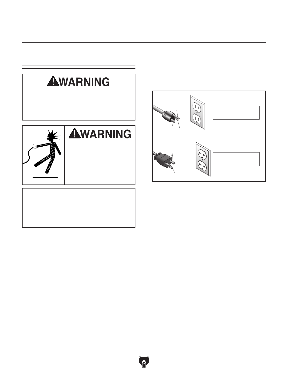
Power Connection Device
The Model G9742 comes prewired with a NEMA
5-15 plug for connection to power. If you rewire the
motor to 220V, we recommend using the plug and
receptacle shown in Figure 2 for 220V.
GROUNDED
5-15 RECEPTACLE
Grounding Prong
5-15 PLUG
Neutral Hot
GROUNDED
6-15 RECEPTACLE
Current Carrying Prongs
6-15 PLUG
Grounding Prong
Figure 2. Recommended plug types.
5-15 Plug & Outlet
for 110V
6-15 Plug & Outlet
for 220V
NOTICE
The Model G9742 is prewired for 110V operation. If you plan to operate your machine
at 220V, the motor must be rewired (see
Page 32).
Full Load Amperage Draw
Amp Draw at 110V (prewired) ..................7 Amps
Amp Draw at 220V ...............................3.5 Amps
Power Supply Circuit Requirements
You MUST connect your machine to a grounded
circuit that is rated for the amperage given below.
Never replace a circuit breaker on an existing circuit with one of higher amperage without consulting a qualified electrician to ensure compliance
with wiring codes. If you are unsure about the
wiring codes in your area or you plan to connect your machine to a shared circuit, consult
a qualified electrician.
Extension Cords
Using extension cords may reduce the life of the
motor. Instead, place the machine near a power
source. If you must use an extension cord:
• For 110V, use at least a 14 gauge cord that
does not exceed 50 feet in length.
• For 220V, use at least a 14 gauge cord that
does not exceed 50 feet in length.
• The extension cord must have a ground wire
and plug pin.
Minimum Circuit Size (110V) ..................15 Amps
Minimum Circuit Size (220V) ................. 15 Amps
G9742 Metal Cutting Bandsaw (Mfg. Since 11/06
-9-
Page 12
SECTION 3: SET UP
Set Up Safety
This machine presents
serious injury hazards
to untrained users. Read
through this entire manual to become familiar with
the controls and operations before starting the
machine!
Wear safety glasses during the entire set up process!
Items Needed for
Set Up
The following items are needed to complete the
set up process, but are not included with your
machine:
Description Qty
• Safety Glasses (for each person) ............... 1
• An Assistant ............................................... 1
• Phillips Head Screwdriver #2 ..................... 1
• Standard Screwdriver #2 ............................ 1
• Hex Wrench 6mm ....................................... 1
• Open-End Wrenches
6, 12, 14, & 19mm ................................ 1 ea.
• Open-End Wrenches
3
⁄8", 7⁄16" & 1⁄2 " ..... 1 ea.
Unpacking
The Model G9742 is a
heavy machine. DO NOT
over-exert yourself while
unpacking or moving
your machine—get assistance.
The Model G9742 was carefully packed to ensure
that it arrives to you safely. If you discover the
machine is damaged after you have signed
for delivery, please immediately call Customer
Service at (570) 546-9663 for advice.
Save the containers and all packing materials for
possible inspection by the carrier or its agent.
Otherwise, filing a freight claim can be difficult.
When you are completely satisfied with the condition of your shipment, you should inventory the
contents.
-10-
G9742 Metal Cutting Bandsaw (Mfg. Since 11/06
Page 13
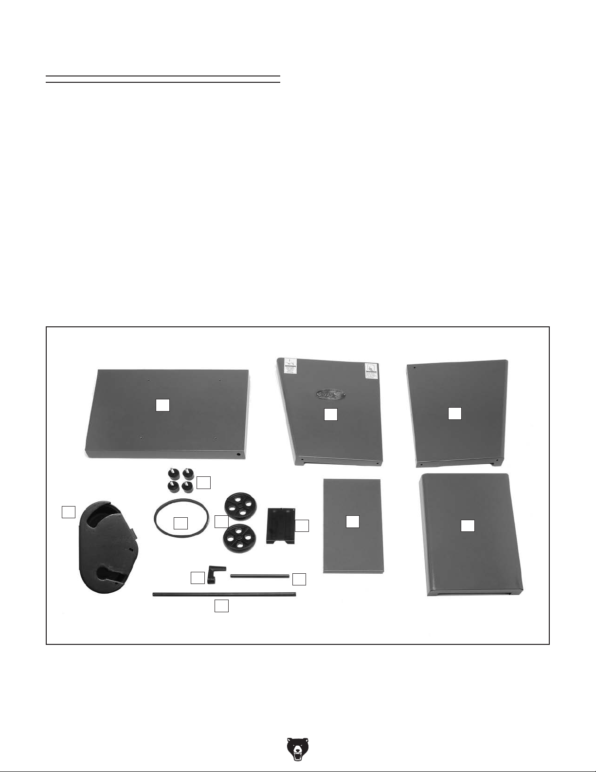
Inventory
After all the parts have been removed from the
box, you should have the following items:
Box 1: (Figure 3) Qty
A. Base ........................................................... 1
B. Front Panel ................................................. 1
C. Rear Panel.................................................. 1
D. Right Panel ................................................. 1
E. Left Panel ................................................... 1
F. Ch ip Tr ay .................................................... 1
G. Feet ............................................................ 4
H. Wheels ....................................................... 2
I. Axle ............................................................ 1
J. Work Stop Shaft ......................................... 1
K. Work Stop ................................................... 1
L. Belt Cover ................................................... 1
M. V-Belt .......................................................... 1
Assembly Hardware:
—Hex Wrench 4mm ................................... 1
3
—Hex Bolt
⁄8 -16 x 1" .................................. 2
—Hex Bolt M8-1.25 x 30 ............................ 4
—Flat Washer 17mm (Wheels) .................. 4
—Flat Washer 8mm ................................... 4
1
—Cotter Pin
—Hex Nut
—Flat Washer
⁄8 x 1 (Wheels) ...................... 2
3
⁄8 -16 (Feet) ............................... 4
3
⁄8 ........................................ 1
—Phillips Head Screw M6-1 x 12 ............. 16
1
—Flat Washer
—Hex Bolt
—Sheet Metal Screw
⁄4 ...................................... 18
1
⁄4 x 20 x 1⁄2 " ............................. 2
1
⁄4-10 x 5⁄16" ............... 1
In the event that any nonproprietary parts are
missing (e.g. a nut or a washer), we would be
glad to replace them, or for the sake of expediency, replacements can be obtained at your local
hardware store.
A
B
C
G
L
M
H
K
F
J
E
D
I
Figure 3. G9742 Loose parts inventory.
G9742 Metal Cutting Bandsaw (Mfg. Since 11/06
-11-
Page 14
Clean Up
Site Considerations
The unpainted surfaces are coated with a waxy
oil to prevent corrosion during shipment. Remove
this protective coating with a solvent cleaner or
degreaser, such as shown in Figure 4. For thorough cleaning, some parts must be removed.
For optimum performance, clean all moving
parts or sliding contact surfaces. Avoid chlo-
rine-based solvents, such as acetone or brake
parts cleaner that may damage painted surfaces. Always follow the manufacturer’s instructions
when using any type of cleaning product.
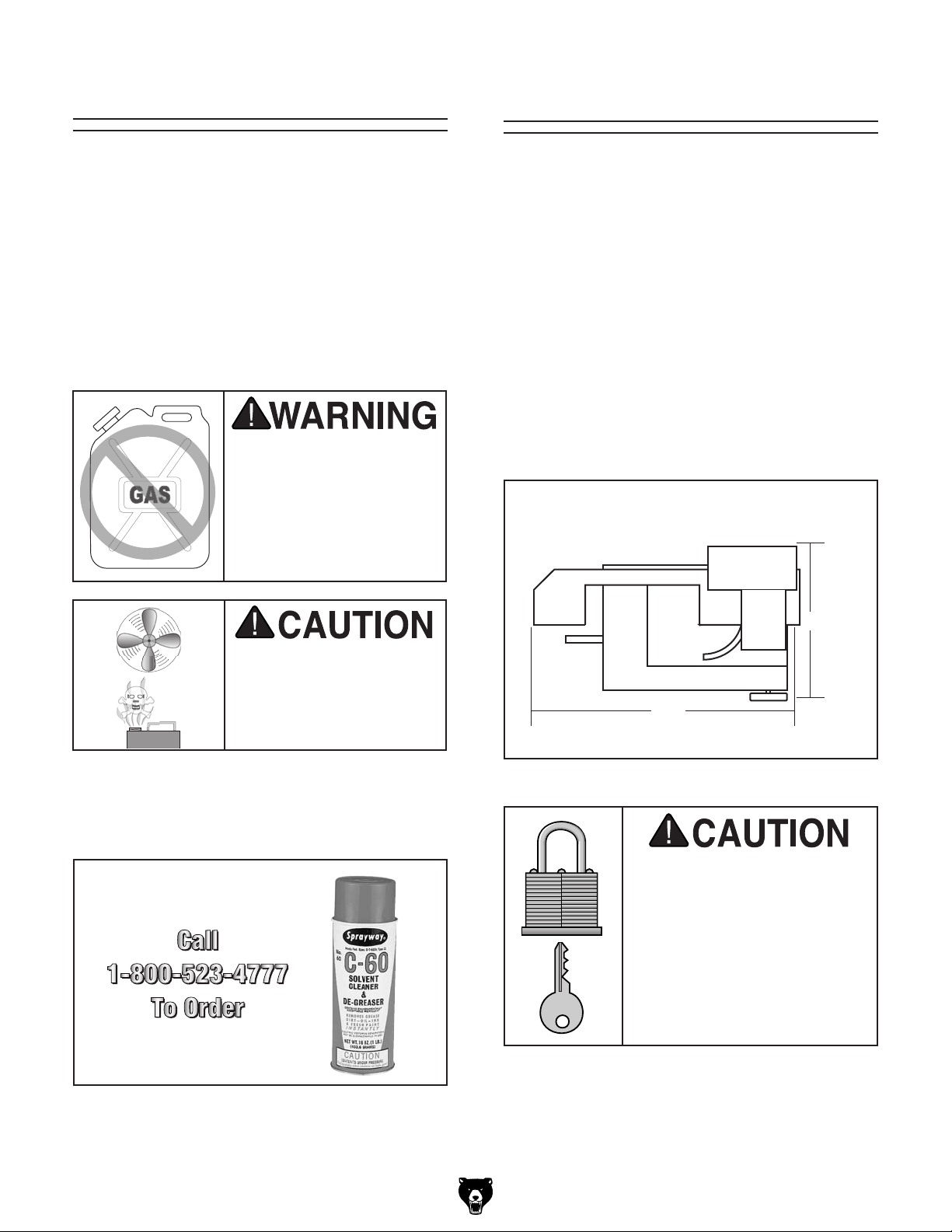
Gasoline and petroleum
products have low flash
points and can explode
or cause fire if used to
clean machinery. DO
NOT use these products
to clean the machinery.
Floor Load
Refer to the Machine Data Sheet for the weight
and footprint specifications of your machine.
Some floors may require additional reinforcement
to support both the machine and operator.
Working Clearances
Consider existing and anticipated needs, size of
material to be processed through each machine,
and space for auxiliary stands, work tables or
other machinery when establishing a location for
your new machine. See Figure 5 for the minimum
working clearances.
Many cleaning solvents
are toxic if inhaled.
Minimize your risk by only
using these products in a
well ventilated area.
G2544—Solvent Cleaner & Degreaser
A great product for removing the waxy shipping
grease from your machine during clean up.
23 3⁄8"
39"
Figure 5. Minimum working clearances.
Unsupervised children and
visitors inside your shop
could cause serious personal injury to themselves.
Lock all entrances to the
shop when you are away and
DO NOT allow unsupervised
children or visitors in your
shop at any time!
Figure 4. Cleaner/degreaser available from
Grizzly.
-12-
G9742 Metal Cutting Bandsaw (Mfg. Since 11/06
Page 15

Cabinet, Wheels &
Feet
This bandsaw is shipped with four rubber feet
with posts and two wheels with an axle. It is your
option to install four rubber feet if you do not
need to move the bandsaw, or install the axle
and wheels if you need to move the bandsaw
re g ul arly.
Components and Hardware Needed: Qty
Base .................................................................. 1
Front Panel ........................................................ 1
Rear Panel ......................................................... 1
Right Panel ........................................................ 1
Left Panel .......................................................... 1
Ramp ................................................................. 1
Feet ................................................................... 4
Wheels............................................................... 2
Axle ................................................................... 1
—Flat Washers 17mm ................................ 4
—Cotter Pins .............................................. 2
—Hex Nuts
—Phillips Head Screw M6-1 x 12 ............. 16
—Flat Washer
—Hex Bolt M8-1.25 x 30 ............................ 4
—Flat Washer 8mm ................................... 4
3
⁄8 -16 ........................................ 4
1
⁄4 ...................................... 16
Figure 6. Installing wheels and feet.
5. Position the base on the floor, and adjust the
feet until the base is level and is stable.
6. Tighten the hex nuts against the base to lock
the feet in position.
7. Position the front and rear panels on the
base and install the panels to the base with
four M6-1 x 12 Phillips head screws and flat
washers (see Figure 7).
To install the wheels, feet, and the cabinet:
1. At the end of the base with the axle holes,
insert the axle into the base (see Figure 6).
2. Slide a 17mm flat washer and wheel onto
each end of the axle, followed by another
washer and cotter pin.
3
3. Thread a
4. Thread the two rubber feet into the base (see
Figure 6).
⁄8-16 hex nut on both feet.
Figure 7. Front and rear panels installed.
G9742 Metal Cutting Bandsaw (Mfg. Since 11/06
-13-
Page 16

8. Position the left panel between the front
and rear panels, and secure it in place with
six M6-1 x 12 Phillips head screws and flat
washers (see Figure 8).
Figure 8. Left Panel installed.
9. Position the right panel between the front
and rear panel, and secure it in place with six
M6-1 x 12 Phillips head screws and flat washers (see Figure 9).
Get assistance when
lifting this machine.
Otherwise, you can
severely injure yourself!
10. With the help of an assistant or a hoisting
device, place the bandsaw onto the cabinet.
11. Secure the bandsaw to the cabinet with four
M8-1.25 x 30 hex bolts and 8mm flat washers
(see Figure 10).
Figure 9. Installing right panel.
Figure 10. Attaching bandsaw to cabinet.
-14-
G9742 Metal Cutting Bandsaw (Mfg. Since 11/06
Page 17

Shipping Strap &
Squaring Vise to
Stop Adjustment
To ensure that your bandsaw arrives without
damage to the hinge system, a shipping strap
was installed. After removing the shipping strap,
you will have to make a series of adjustments,
beginning with the feed stop bolt.
To remove the shipping strap and adjust the
feed stop bolt:
1. Remove the shipping strap hex bolt and
strap with a 12mm wrench (see Figure 11).
Note: Keep this shipping strap in the event that
you must transport or ship the bandsaw.
2. Adjust the feed stop bolt and jam nut with a
14mm wrench (Figure 12), so the bandsaw
blade teeth are just below the table surface
when the cut is complete.
Blade
To ensure that your bandsaw will make cuts that
match the degree scale, you must make sure to
square the vise to the blade.
To square the vise to the blade:
1. Rotate the headstock until the pointer reads
"0" on the tabletop scale, and tighten the
headstock lock lever so the headstock stays
indexed at zero.
2. Using a 6mm wrench, loosen the two cap
screws that hold the vise to the table (see
Figure 13).
Square
Headstock
Lock Lever
Figure 11. Removing shipping strap.
Figure 12. Feed stop bolt.
G9742 Metal Cutting Bandsaw (Mfg. Since 11/06
Figure 13. Squaring vise to blade, headstock,
and table scale.
3. Using a small machinists square, adjust the
vise so it is square to the blade.
4. Tighten the two cap screws, so the vise and
blade are square with one another.
-15-
Page 18

Chip Tray & Cast
Iron Stop
The chip tray directs small workpieces into a bucket when the cut is complete. The cast iron stop
allows you to repeat cuts at the same length.
OFF Button Lever
After you have removed the shipping strap and
have adjusted the headstock stop bolt, you must
adjust the OFF button lever stop bolt, so the
bandsaw shuts OFF automatically when a cut is
complete.
To install the chip tray and cast iron stop:
1. Position the chip tray as shown in Figure 14
if you choose to use this accessory.
Chip tray
Figure 14. Chip tray installed.
2. Insert the stop rod approximately 3⁄4" into the
saw until the end of the rod is just flush with
the inside casting surface.
To set the OFF button lever stop bolt:
1. With the headstock in the complete down
position, loosen the 12mm stop bolt and jam
nut (see Figure 16).
Stop Bolt and
Jam Nut
OFF Button
Figure 16. OFF button lever and stop bolt.
3. Using the 4mm hex wrench, tighten the set
screw shown in Figure 15.
Set Screw
Set Screw
Figure 15. Installing stop rod.
4. Slide the cast iron stop onto the stop rod
and tighten the set screw.
2. Push down on the OFF button lever so the
button is completely depressed.
3. While keeping the lever depressed, use your
fingertips to turn the stop bolt until the head
touches the lever.
1
4. Back off the stop bolt
jam nut.
⁄3 turn and tighten the
-16-
G9742 Metal Cutting Bandsaw (Mfg. Since 11/06
Page 19

Pulley Cover
When opened, the pulley cover gives you access
to change the pulley ratio so the bandsaw can cut
at one of three speeds.
ENTANGLEMENT
HAZARD! You MUST
install the pulley cover
before operating!
Otherwise, severe injury
may occur.
To install the pulley cover:
4. Loosen the belt tension knob enough to
install the belt on the appropriate pulley that
will give the required blade speed. Refer to
Blade Speed on Page 19 for blade speed
selections.
5. Adjust the belt tension knob (Figure 18), so
the belt has
the center, and close the cover.
1
⁄4" deflection when pressed in
1. UNPLUG THE BANDSAW!
2. Position and rotate the pulley cover into
place as shown in Figure 17.
1
3. Install the two
ers that secure the pulley cover.
⁄4-20 x 1⁄2" hex bolts and wash-
Belt Tension
Knob
Figure 18. Belt tension knob.
Figure 17. Positioning the pulley cover.
G9742 Metal Cutting Bandsaw (Mfg. Since 11/06
-17-
Page 20

Test Run
Recommended
Adjustments
Projectiles thrown from
the machine could cause
serious eye injury. Wear
safety glasses during
assembly and operation.
Starting the machine:
1. Read the entire instruction manual.
2. Make sure all tools and foreign objects have
been removed from the machine.
3. Put on safety glasses and secure loose
clothing or long hair.
4. Raise the bandsaw by the handle.
5. Start the bandsaw while keeping your finger
near the ON/OFF switch at all times during the test run. The bandsaw should run
smoothly with little or no vibration.
The adjustments listed below have been performed at the factory. However, because of
the many variables involved with shipping, we
recommend that you at least verify the following
adjustments to ensure the adjustments remain
unchanged.
Step-by-step instructions on verifying these
adjustments can be found in SECTION 6:
MAINTENANCE on Page 26 and SECTION 7:
SERVICE on Page 27.
Factory adjustments that should be verified:
1. Blade Tracking (Page 30).
2. Squaring Vise to Blade (Page 15).
3. Blade Guides (Page 22).
— If you suspect any problems, immediately
stop the bandsaw and correct before continuing.
—If you need any help with your bandsaw
call our Tech Support at (570) 546-9663.
-18-
G9742 Metal Cutting Bandsaw (Mfg. Since 11/06
Page 21

SECTION 4: OPERATIONS
Operation Safety
Damage to your eyes, lungs, and ears could
result from using this machine without
proper protective gear. Always wear safety
glasses, a respirator, and hearing protection
when operating this machine.
Loose hair and clothing could get caught in
machinery and cause serious personal injury. Keep
loose clothing and long
hair away from moving
machinery.
NOTICE
If you have never used this type of machine
or equipment before, WE STRONGLY RECOMMEND that you read books, trade magazines, or get formal training before beginning any projects. Regardless of the content in this section, Grizzly Industrial will
not be held liable for accidents caused by
lack of training.
Blade Speed
The Model G9742 has these three blade speeds:
80, 120, and 200 FPM.
To change blade speeds:
1. UNPLUG THE BANDSAW!
2. Determine the best speed for your cut. The
table in Figure 19 is provided as a basic
guideline. Material thickness and the type of
blade used will factor into FPM selection.
Material Feet Per Minute
(FPM)
Aluminum 250
Plastics 800
Brass (soft) 500
Carbon Tool Steel 100-150
Cast Iron 100-150
Cold Rolled Steel 150-200
High Speed Steel 90-125
Malleable Iron 150-200
Hard Rubber 150-200
Figure 19. Blade speed table.
3. Slacken the V-belt and position it for the
desired FPM (see Figure 20).
80
120
200
Motor Pulley
Wheel Pulley
G9742 Metal Cutting Bandsaw (Mfg. Since 11/06
Figure 20. V-belt positions in FPM.
4. Tension the V-belt as described in the Pulley
Cover section on Page 17.
-19-
Page 22

Blade Selection
The chart below is a basic starting point for choosing blade type based on teeth per inch (TPI) for
variable tooth pitch blades and for standard raker
type bimetal blades/HSS blades. However, for
exact specifications of bandsaw blades, contact
the blade manufacturer.
Here are some general rules of thumb with
respect to bandsaw blade use.
• At least three teeth must contact the metal
at any phase of the cut. Otherwise, the teeth
can load up with metal, fracture, and break
off. If the TPI is too high, the teeth can load
up with material and overheat, damaging the
blade.
• For a faster but rougher cut, use a blade with
a lower TPI and a higher feed rate.
• For a slower but smoother cut, use a blade
with more TPI and a lower feed rate.
To select the correct blade TPI:
1. Measure the material thickness. This mea-
surement is the length of cut taken from
where the tooth enters the workpiece, sweeps
through, and exits the workpiece.
2. Refer to the "Material Thickness" row of the
blade selection chart in Figure 21, and read
across to find the workpiece thickness you
need to cut.
3. Refer to the "Shape" of metal and "Material
Type" columns, and find the shape and
material to be cut.
4. In the applicable row, read across to the right
and find the box where the row and column
intersect. Listed in the box is the minimum
TPI recommended for the variable tooth pitch
blades, and the TPI for bimetal raker blades
in parentheses.
TOOTH SELECTION
mm
50
inch
2 3 4 5 6 7 8 9 10 11 12 13 14 15 16 17 18 192½ 3½
75 100 150 200 250 300 350 400
3/4
4/6
5/8
3/4
3/4
4/6
2/3
2/3 1.4/2.5
CUTTING SPEED RATE RECOMMENDATION
Material
Carbon
Steel
Angle
Steel
Thin
Tube
Aluminum
Alloy
Copper
Alloy
Speed FPM
(M/Min)
196~354
(60) (108)
180~220
(54) (67)
180~220
(54) (67)
220~534
(67) (163)
229~482
(70) (147)
Material Material Material
Tool Steel
High-Speed
Tool Steel
Cold-Work
Tool Steel
Hot-Work
Tool Steel
Oil-Hardened
Tool Steel
Speed FPM
(M/Min)
203
(62)
75~118
(25) (36)
95~213
(29) (65)
203
(62)
203~213
(62) (65)
Alloy
Steel
Mold Steel
Water
Hardened
Tool Steel
Stainless
Steel
CR Stainless
Steel
1.4/2.5
Speed FPM
(M/Min)
111~321
(34) (98)
246
(75)
242
(75)
85
(26)
85-203
(26) (62)
2/3
1.5/.8
Free Machining
Stainless Steel
Gray
Cast Iron
Ductile
Austenitic
Cast Iron
Malleable
Cast Iron
Plastics
450
1.5/.8
Speed FPM
(M/Min)
150~203
(46) (62)
108~225
(33) (75)
65~85
(20) (26)
321
(98)
220
(67)
-20-
Figure 21. Blade selection chart.
G9742 Metal Cutting Bandsaw (Mfg. Since 11/06
Page 23

Feed Rate
The speed at which the saw blade will cut through
a workpiece is controlled by blade type and feed
rate.
The feed rate is controlled by the valve lever and
feed rate dial on the hydraulic cylinder shown in
Figure 22.
To set the feed rate:
1. Raise the headstock and turn the valve lever
sideways (horizontally).
2. Clamp the workpiece in the table vise.
3. Move the headstock and blade a few inches
above the workpiece.
4. With the correct saw blade installed and
blade speed selected, turn the saw ON.
Valve Lever
Feed Rate Dial
Figure 22. Bandsaw feed rate control.
Turning the valve lever in-line with the piping (as
shown in the Figure 22) opens it up, which allows
the fluid to circulate and allows the head to move.
Turning the valve lever sideways or perpendicular
to the pipiing closes it, which locks the headstock
in place.
The feed rate dial controls the amount of fluid that
circulates around the hydraulic cylinder, which in
turn, controls the speed that it moves.
5. Slowly rotate the feed rate dial to a conservative feed rate until the saw begins to cut the
workpiece.
6. Observe the chips that exit the cut, and
increase or decrease the feed rate according
to the chip characteristics (see Figure 23).
Chips are width
of tooth, thin and
curled, and silvery:
Optimum speed and
feed rate.
Chips are silvery,
thin, small, or
powdery: Increase
feed rate.
Chips are large,
curled, blue or
brown, or smoking:
Decrease feed rate.
G9742 Metal Cutting Bandsaw (Mfg. Since 11/06
Figure 23. Reading chips.
-21-
Page 24

Blade Guides
UNPLUG the bandsaw
power cord, and NEVER
adjust the blade guides
while the saw blade is
moving!
The blade guide side bearings support and twist
the blade straight so the blade will enter the
workpiece perpendicular to the table surface. The
blade guide support bearings prevent blade twist
by stopping the blade from being pushed back
during a cut. Both adjustments are critical for correct saw operation (see Figure 24).
Guide Bearing
Adjustment
Hex Bolt
Side Bearing
Eccentric and
Jam Nut
Blade Guide Support Bearing
Side Bearing
Eccentric
and Jam Nut
Figure 25. Blade guide adjustments.
4. Adjust the blade guide housing so the sup-
port bearing rests against the rear of the
blade (see Figure 24).
5. Using a 14mm wrench, loosen the outer side
bearing eccentric jam nuts.
6. Using a 12mm wrench, rotate the side bearing eccentrics until the bearings have a bearing-to-blade clearance of 0.000" to 0.001".
The bearings must not pinch the blade and
the blade needs to be perpendicular to the
table.
Guide Bearing
Adjustment Hex Bolt
Blade Guide
Side Bearing
Figure 24. Blade guide adjustment locations.
To adjust the guide bearings:
Note: Make sure the blade is tensioned and
tracks correctly before you adjust the blade guide
bearings. Refer to Blade Tension and Blade
Tracking on Pages 23 and 30 for further instructions.
1. UNPLUG THE BANDSAW!
2. Let the bandsaw headstock park in the full
down position.
3. Using a 12mm wrench, loosen the guide
bearing adjustment hex bolt (see Figure 25).
7. Tighten the jam nuts, loosen the lock knob,
and slide the blade guide close to the
workpiece so the blade is supported and will
not twist during the cut (see Figure 26).
Lock Knob
Figure 26. Blade guide position lock knob.
-22-
G9742 Metal Cutting Bandsaw (Mfg. Since 11/06
Page 25

Blade Tension
Proper blade tension is essential to long blade life,
straight cuts, and efficient cutting.
Two major signs that you do not have proper
blade tension are: 1) the blade stalls in the cut and
slips on the wheels, and 2) the blade frequently
breaks from being too tight.
To tension the blade on the bandsaw:
1. Make sure the blade is tracking properly.
2. UNPLUG THE BANDSAW!
• Let the blade reach full speed before engaging the workpiece. Never start a cut with the
blade in contact with the workpiece (see
Figure 27).
• Chips should be curled and silvery. If the
chips are thin and powder like, increase your
feed rate.
• Burned chips indicate a need to reduce your
blade speed.
• Wait until the blade has completely stopped
before removing the workpiece from the vise,
and avoid touching the cut end—it could be
very hot!
3. Slide the blade guides as far apart as they
will go, then tighten them down again.
4. Turn the tension knob clockwise to tighten
the blade, or counterclockwise to loosen the
blade.
Note: To fine tune blade tension, use a
blade tensioning gauge, like the one found in
SECTION 5: ACCESSORIES on Page 24.
Please follow the instructions included with
your gauge and the blade manufacturer's
recommendations on blade tension.
Operation Tips
The following tips will help you safely and effectively operate your bandsaw, and help you get the
maximum life out of your saw blades.
• Support long pieces so they won't fall when
cut, and flag the end to alert passers-by of
potential danger.
• Adjust the blade guides as close as possible
to the workpiece to minimize side-to-side
blade movement.
• Use coolant when possible to increase blade
life.
Work Stop
Tips for horizontal cutting:
• Use the work stop to quickly and accurately
cut multiple pieces of stock to the same
length.
• Clamp the material firmly in the vise jaws to
ensure a straight cut through the material,
and use the positive lock to speed production.
G9742 Metal Cutting Bandsaw (Mfg. Since 11/06
Figure 27. Typical proper starting position.
-23-
Page 26

ACCESSORIES
SECTION 5: ACCESSORIES
G5107— 64 -1/ 2 x 1/2 x .025 10 TPI Raker
G5108—64-1/2 x 1/2 x .025 14 TPI Raker
G5109—64-1/2 x 1/2 x .025 18 TPI Raker
G5110—64-1/2 x 1/2 x .025 24 TPI Raker
G5111—64-1/2 x 1/2 x .025 6-10 Variable Pitch
G5112—64-1/2 x 1/2 x .025 8-12 Variable Pitch
G5113 — 6 4 -1 / 2 x 1/2 x .025 10-14 Variable Pitch
G5114 — 6 4 -1/ 2 x 1/2 x .025 14-18 Variable Pitch
G5115 — 64 -1/ 2 x 1/2 x .025 20-24 Variable Pitch
®
Power Tw ist
H9815—A
A smart upgrade for any machine that uses
V-belts. These link belts provide smooth running
with less vibration, heat, and noise than solid
belts. Power Twist
in minutes to any size—just add or remove sections to fit your needs. Once you use a link belt,
you'll like it so much you'll want to convert all your
machines!
V-Belts
1
⁄2" x 4'
®
V-Belts can be customized
Figure 28. Blades.
H5408—Blade Tensioning Gauge
The Blade Tensioning Gauge ensures long blade
life, reduced blade breakage, and straight cutting
by indicating correct tension. A precision dial indicator provides you with a direct readout in PSI.
Figure 29. H5408 blade tensioning gauge.
Figure 30. Power Twist® V-Belt.
T20640—Machinery’s Handbook
For more than 90 years, this handbook has been
the benchmark by which machinists’ and engineering texts have been judged. Includes a wealth
of information on mathematics, mechanics, measurements, and materials. A must have for the
amateur or professional.
-24-
Figure 31. Machinery’s Handbook.
G9742 Metal Cutting Bandsaw (Mfg. Since 11/06
Page 27

G5618—Deburring Tool w/ 2 Blades
G5619—Extra Aluminum Blades
G5620—Extra Brass and Cast Iron Blade
The quickest tool for smoothing freshly machined
metal edges. Comes with two blades—one for
steel/aluminum and one for brass/cast iron.
Figure 32. G5618 deburring tool.
T20501—Face Shield Crown Protector 4"
T20502—Face Shield Crown Protector 7"
T20503—Face Shield Window
T20448—Economy Clear Safety Glasses
T20452—"Kirova" Anti-Reflective Glasses
T20456—"Dakura" Clear Safety Glasses
®
H0736—Shop Fox
Safety Glasses
These glasses meet ANSI Z87.1-2003 specifications. Buy extras for visitors or employees. You
can't be too careful with shop safety!
G7615—Oil Can w/Steel Nozzle
G7616—Oil Can w/Plastic Nozzle
G7617—Oil Can w/Flexible Plastic Nozzle
Whether you’re lubricating cutting tools or maintaining machinery in top operating condition, you’ll
appreciate these High Pressure Oil Cans. Each
can holds 5 ounces of oil and has a trigger activated, high pressure pump.
Figure 34. High pressure oil cans.
G9256—6" Dial Caliper
G9257—8" Dial Caliper
G9258—12" Dial Caliper
These traditional dial calipers are accurate to
0.001" and can measure outside surfaces, inside
surfaces, and heights/depths. Features stainless
steel, shock resistant construction and a dust
proof display.
T20502
T20452
T20503
T20448
T20456
H0736
Figure 33. Our most popular eye protection.
G9742 Metal Cutting Bandsaw (Mfg. Since 11/06
Figure 35. Grizzly® dial calipers.
-25-
Page 28

SECTION 6: MAINTENANCE
Always disconnect power
to the machine before
performing maintenance.
Failure to do this may
result in serious personal injury.
Schedule
For optimum performance from your machine,
follow this maintenance schedule and refer to any
specific instructions given in this section.
Daily Check
• Loose mounting bolts.
• Damaged saw blade.
• Worn or damaged wires.
• Any other unsafe condition.
• Clean after each use.
• Proper blade tension.
Monthly Check
• Lubricate vise screw.
• Check V-Belt for wear.
Lubrication
The gearbox and all bearings are sealed and permanently lubricated so no scheduled lubrication is
needed. However, you must periodically lubricate
adjustment locations and bare metal surfaces.
Refer to Figure 36 for lubrication points.
Lubricate the following areas listed below:
A. Blade Tension Mechanism: Open the main
blade guard, and drop a few drops of oil on
the tension knob lead screw.
B. Blade and Guides: Drop a few drops of
light machine oil on the blade and the blade
guides daily.
C. Gear Box: Is packed with grease and should
only be changed if you suspect contamination has entered.
D. Table and Machined Surfaces: Keep bare
metal surfaces rust-free with regular applications of products like SLIPIT®. For long term
storage you may want to consider products
like Boeshield T-9™.
Annual Check
• Inspect gear lubrication.
Cleaning
Cleaning the Model G9742 is relatively easy.
Keeping metal chips away from bandsaw mechanisms is important to making sure that your
bandsaw lasts a long time. Use a shop vacuum
or brush off metal chips frequently.
-26-
E. Vise Lead Screw: Drop a few drops of light
machine oil on the vise lead screw weekly.
A
E
D
Figure 36. Lubrication points.
G9742 Metal Cutting Bandsaw (Mfg. Since 11/06
B
C
Page 29

SECTION 7: SERVICE
Review the troubleshooting and procedures in this section to fix your machine if a problem develops. If you
need replacement parts or you are unsure of your repair skills, then feel free to call our Technical Support
at (570) 546-9663.
Troubleshooting
Motor & Electrical
Symptom Possible Cause Possible Solution
Machine does not start
or a breaker trips.
Machine stalls or is
underpowered.
Machine has vibration
or noisy operation.
1. Plug/receptacle is at fault or wired incorrectly.
2. Start capacitor is at fault.
3. Wall fuse/circuit breaker is blown/tripped.
4. Motor connection wired incorrectly.
5. Power supply is at fault/switched OFF.
6. Motor ON/OFF switch is at fault.
7. Wiring is open/has high resistance.
8. Motor is at fault.
1. Wrong blade for the workpiece material.
2. Wrong workpiece material.
3. Feed rate/cutting speed too fast for task.
4. Blade is slipping on wheels.
5. Low power supply voltage.
6. Motor bearings are at fault.
7. Plug/receptacle is at fault.
8. Motor connection is wired incorrectly.
9. Motor has overheated.
10. Motor is at fault.
1. Motor fan is rubbing on fan cover.
2. Blade is at fault.
3. Gearbox is at fault.
4. Wrong blade & too slow of speed.
1. Test for good contacts; correct the wiring.
2. Test/replace if faulty.
3. Ensure correct size for machine load; replace
weak breaker.
4. Correct motor wiring connections.
5. Ensure hot lines have correct voltage on all
legs and main power supply is switched ON.
6. Replace faulty ON/OFF switch.
7. Check for broken wires or disconnected/
corroded connections, and repair/replace as
necessary.
8. Test/repair/replace.
1. Use blade with correct properties for your type
of cutting.
2. Use metal with correct properties for your type
of cutting.
3. Decrease feed rate/cutting speed.
4. Adjust blade tracking and tension.
5. Ensure hot lines have correct voltage on all
legs.
6. Test by rotating shaft; rotational grinding/loose
shaft requires bearing replacement.
7. Test for good contacts; correct the wiring.
8. Correct motor wiring connections.
9. Clean off motor, let cool, and reduce
workload.
10. Test/repair/replace.
1. Replace dented fan cover; replace loose/
damaged fan.
2. Replace/resharpen blade.
3. Rebuild gearbox for bad gear(s)/bearing(s).
4. Change blade and or speed.
G9742 Metal Cutting Bandsaw (Mfg. Since 11/06
-27-
Page 30

Bandsaw Operations
SYMPTOM POSSIBLE CAUSE CORRECTIVE ACTION
Machine is loud when
cutting or bogs down in
the cut.
Blades break often. 1. Blade is not tensioned correctly.
Blade dulls prematurely. 1. The cutting speed is too fast.
Blade wears on one side. 1. The blade guides are worn or mis-
Teeth are ripping from the
blade.
The cuts are crooked. 1. The feed pressure is too high.
1. Excessive feed rate.
2. The blade TPI is too great, or the
material is too coarse.
2. The workpiece is loose in the vise.
3. The feed or cut speed is wrong.
4. The blade TPI is too great, or the
material is too coarse.
5. The blade is rubbing on the wheel
flange.
6. The bandsaw is being started with
the blade resting on the workpiece.
7. The guide bearings are
misaligned, or the blade is rubbing
on the wheel flange.
8. The blade is too thick, or the
blades are of low quality.
2. The blade TPI is too coarse.
3. The blade feed pressure is too
light.
4. The workpiece has hard spots,
welds, or scale is on the material.
5. The blade is twisted.
6. The blade is slipping on the
wheels.
adjusted.
2. The blade guide slide bracket is
loose.
3. The wheels are out of alignment.
1. The feed pressure is too heavy
and the blade speed is too slow; or
the blade TPI is too coarse for the
workpiece.
2. The workpiece is vibrating in the
vise.
3. The blade gullets are loading up
with chips.
2. The guide bearings are out of
adjustment, or too far away from
the workpiece.
3. The blade tension is low.
4. The blade is dull.
5. The blade speed is wrong.
1. Refer to Feed Rate on Page 21, or Changing
Blade Speed on Page 19, and adjust as required.
2. Refer to Blade Selection on Page 20 and adjust as
required.
1. Check to see that blade is not excessively tight or
too loose.
2. Clamp the workpiece tighter, or use a jig to hold the
workpiece.
3. Refer to Feed Rate on Page 21, or Changing
Blade Speed on Page 19, and adjust as required.
4. Refer to Blade Selection on Page 20 and adjust as
required.
5. Refer to Blade Tracking on Page 30, and adjust as
required.
6. Start bandsaw and then slowly lower the headstock
by setting the feed rate.
7. Refer to Blade Tracking on Page 30, or Blade
Guides on Page 22 and adjust as required.
8. Use a higher quality blade.
1. Refer to Changing Blade Speed on Page 19, and
adjust as required.
2. Refer to Blade Selection on Page 20 and adjust as
required.
3. Refer to Feed Rate on Page 21, and adjust as
required.
4. Increase the feed pressure, and reduce the cutting
speed.
5. Replace the blade.
6. Refer to Blade Tension on Page 23, and adjust as
required.
1. Refer to Blade Guides on Page 22 and replace or
adjust.
2. Tighten the blade guide bracket.
3. Refer to Blade Tracking on Page 30, and adjust as
required.
1. Refer to Blade Selection on Page 20 and decrease
the feed pressure. Refer to Feed Rate on Page 21,
and adjust as required.
2. Re-clamp the workpiece in the vise, and use a jig if
required.
3. Use a coarser-tooth blade.
1. Refer to Feed Rate on Page 21, and adjust as
required.
2. Refer to Blade Guides on Page 22 and replace or
adjust.
3. Refer to Blade Tension on Page 23, and adjust as
required.
4. Refer to Changing the Blade on Page 29 and
replace the blade.
5. Refer to Changing Blade Speed on Page 19, and
adjust as required.
-28-
G9742 Metal Cutting Bandsaw (Mfg. Since 11/06
Page 31

Blade Change
Blades should be changed when they become
dull, damaged, or when you are using materials
that require a blade of a certain type or tooth
count.
To change the bandsaw blade:
1. UNPLUG THE BANDSAW!
2. Hold the headstock, unattach the feed cyl-
inder by removing the cap screw, then raise
the headstock to the full vertical position (see
Figure 37).
4. Loosen the tension knob and slip the blade
off of the wheels.
5. Install the new blade through both blade
guide bearings, as shown in Figure 39, and
around the bottom wheel.
Figure 39. Typical blade installation.
Feed Cylinder
Cap Screw
Figure 37. Disengaging the feed cylinder.
3. Push the safety stop in, use a screwdriver
to remove the upper and lower blade guide
guards, and loosen the blade guides (see
Figure 38).
Safety
Stop
Figure 38. Blade guide guards and fasteners.
Blade
Guide
Guards
6. Hold the blade around the bottom wheel with
one hand and slip it around the top wheel with
the other hand, keeping the blade between
the blade guide bearings.
Note: It is sometimes possible to flip the
blade inside out, in which case the blade will
be installed in the wrong direction. Check to
make sure the blade teeth are facing toward
the workpiece, as shown in Figure 39, after
mounting on the bandsaw. Some blades will
have a directional arrow as a guide.
7. When the blade is around both wheels,
adjust the position so the back of the blade is
against the shoulder of the wheels.
8. Tighten the tension knob as tight as necessary so the blade will not slip on the wheels
during start up.
9. Spin the wheel by hand until the blade
resumes the previous tracking.
—If the tracking needs to be adjusted, refer
to the Tracking procedure in the next section.
—If the tracking is fine, proceed to Blade
Tension on Page 23.
G9742 Metal Cutting Bandsaw (Mfg. Since 11/06
-29-
Page 32

10. Reinstall the blade guards, and adjust the
blade guides as described in Blade Guides
on Page 22
7. Adjust the tracking set screw with a 4mm hex
wrench as shown in Figure 40, then tighten
the cap screw loosened in Step 5.
11. Re-attach the feed cylinder.
Blade Tracking
The blade tracking has been properly set at
the factory. The tracking will rarely need to be
adjusted if the bandsaw is used properly.
To adjust the blade tracking on the bandsaw:
1. UNPLUG THE BANDSAW!
2. Raise the headstock and lock it in place by
pushing in the safety stop knob.
3. Remove both blade guide assemblies.
4. Open the wheel access cover.
5. Loosen, but do not remove the lower cap
screw in the blade wheel tilting mechanism
(Figure 40).
—Tightening the set screw will move the
blade closer to the shoulder of the wheel.
—Loosening the set screw will move the
blade away from the shoulder.
8. Tension the blade.
9. Spin the wheel by hand and observe how the
blade tracks on the wheel.
—If the blade tracks along the shoulder of
the wheel (without rubbing), the blade is
tracking properly and this adjustment is
completed.
—If the blade drifts away from the shoulder
of the wheel or hits the shoulder, repeat
Steps 5-8.
10. Replace the blade guard and blade guide
assemblies.
11. Adjust the blade guides as needed. Refer to
Blade Guides on Page 22
Tracking
Set Screw
Lower Cap Screw
Figure 40. Adjusting tracking set screw.
6. Relax the blade tension.
-30-
G9742 Metal Cutting Bandsaw (Mfg. Since 11/06
Page 33

Electrical Components
Figure 41. Capacitor
Figure 42. Switch wiring right-hand view.
Figure 43. Switch wiring rear view.
Figure 44. Switch wiring left-hand view.
G9742 Metal Cutting Bandsaw (Mfg. Since 11/06
-31-
Page 34

220 Wiring
G9742 Wiring Diagram
Disconnect power from
machine before performing
any electrical service. Failure
to do this will result in a
shock hazard leading to
injury or death.
110V
Power Supply
Load
Hot
Neutral
Neutral
Green
Green
White
Black
Paddle
Switch
220V
Power Supply
Ground
Ground
110V
Connection
Green
Neutral
White
Black
Hot
Bandsaw Motor
Electrical Box
220V
Red
Red
Black
Black
Gray
Gray
Yellow
Yellow
Motor
Motor
Bandsaw Motor
Capacitor Cover
Wire number
Wire Color
1 = Black
2 = Yellow
3 = Red
4 = Gray
Capacitor
Capacitor
-32-
Load
Hot
White
Black
Neutral
Hot
Ground
Ground
Green
Paddle
Switch
Connection
Green
Hot
White
Black
Hot
Bandsaw Motor
Electrical Box
Capacitor
Capacitor
Motor
Motor
Bandsaw Motor
Capacitor Cover
Red
Black
Black
Gray
Yellow
Yellow
G9742 Metal Cutting Bandsaw (Mfg. Since 11/06
Red
Gray
Wire number
Wire Color
1 = Black
2 = Yellow
3 = Red
4 = Gray
Page 35

Saw Parts Breakdown
75
101
100
80
79
75
109
108
101-1
182
35
50
72
89
31
112
104
103
109
81
83
100
72
73
93
92
120
2
123
84
134
71
98
8
133
1
11
97
8
12
320
35
102
132
201
76
200
199
66
35
132-1
102
97
59
11
58
3
48
51
50
71-1
198
113
G9742 Metal Cutting Bandsaw (Mfg. Since 11/06
-33-
Page 36

Saw Parts List
REF PART # DESCRIPTION REF PART # DESCRIPTION
1 PB07 HEX BOLT 5/16-18 X 3/4 92 P9742092 GEAR BOX GASKET
2 PN05 HEX NUT 1/4-20 93 P9742093 COVER
3 PW06 FLAT WASHER 1/4 97 PS08M PHLP HD SCR M5-.8 X 12
8 PW07 FLAT WASHER 5/16 98 P9742098 KNOB 5/16-18 X 45
11 PB03 HEX BOLT 5/16-18 X 1 100 PS23 PHLP HD SCR 8-32 x 1/4
12 PN02 HEX NUT 5/16-18 101 P9742101 WORM GEAR PULLEY
31 PB03 HEX BOLT 5/16-18 X 1 101-1 PSS38 SET SCREW 5/16-18 X 5/8
35 PLW04 LOCK WASHER 3/8 102 PLW01 LOCK WASHER 5/16
48 PS06 PHLP HD SCR 10-24 X 3/8 103 P9742103 BLADE TENSION SLIDING PLATE
50 PB07 HEX BOLT 5/16-18 X 3/4 104 PSS38 SET SCREW 5/16-18 X 5/8
51 PW07 FLAT WASHER 5/16 108 P9742108 SHAFT BLOCK
58 P9742058 KNOB 1/4-20 X 5/8 109 P9742109 BLADE TENSION SLIDING GUIDE
59A P9742059A BLADE BACK SAFETY COVER V2.11.06 112 PVA22 V-BELT A-22 4L220
66 P9742066 KNOB 3/8-16 X 1-1/4 113 G5109 BLADE 64-1/2 X 1/2 X.025
71 P9742071 BLADE WHEEL FRONT 120 P9742120 BUSHING 19 X 17 X 7
71-1 PSS17 SET SCREW 5/16-18 X 5/16 123 PB05 HEX BOLT 1/4-20 X 3/4
72 P9742072 BEARING COVER 132 P9742132 SAFETY GUARD RIGHT
73 PK23M KEY 5 X 5 X 25 133 PS06 PHLP HD SCR 10-24 X 3/8
75 PB02 HEX BOLT 1/4-20 X 5/8 134 P9742134 WIRE CLAMP
76 P9742076 SWITCH CUT OFF TIP 182 PW07 FLAT WASHER 5/16
79 P9742079 BLADE TENSION ADJ KNOB 198 PR05M EXT RETAINING RING 15MM
80 P9742080 COMPRESSION SPRING 199 PB03 HEX BOLT 5/16-18 X 1
81 P9742081 BODY FRAME 200 PSB04 CAP SCREW 1/4-20 X 1/2
83 PB41 HEX BOLT 1/2-12 X 1-1/2 201 PN02 HEX NUT 5/16-18
84 P9742084 MOTOR MOUNT PLATE 320 PB58 HEX BOLT 3/8-16 X 2
89 P9742089 OIL SEAL
-34-
G9742 Metal Cutting Bandsaw (Mfg. Since 11/06
Page 37

Stand Parts Breakdown
27
85-2
28
194
85-1
307
196V2
111
126
85-3
85-4
305V2
124
302V2
301V2
126
125
313
312
86-1
86
303V2
314
16
74
312
308
311
44
85
319
310
309
318
322
320
11
304
315
50
321
338
51
324
54
325
323
17
328
329
362
363
255
258
254
262
259
263
261
256
257
330A-1
21
19
20
334
359
366
316
300
367
368
364
363
361
330A
333
9
G9742 Metal Cutting Bandsaw (Mfg. Since 11/06
-35-
Page 38

Stand Parts List
REF PART # DESCRIPTION REF PART # DESCRIPTION
9 P9742009 WHEEL 302A P9742302A VISE JAW BRACKET-FRONT V2.01.08
11 PB03 HEX BOLT 5/16-18 X 1 303A P9742303A VICE JAW BRACKET-REAR V2.01.08
16 P9742016 MOTOR CABLE 304 P9742304 SWIVEL BASE UPPER
17 P9742017 PIVOTING ROD 305A P9742305A BRACKET W/NUT V2.01.08
19 P9742019 WORK STOP 306 P9742306 ACME NUT
20 PSS17 SET SCREW 5/16-18 X 5/16 307A P9742307A ACME SCREW V2.01.08
21 P9742021 STOCK STOP ROD 1/2 X 216 308 P9742308 BUSHING
27 P9742027 HANDWHEEL HANDLE 309 PLW01 LOCK WASHER 5/16
28 P9742028 HANDWHEEL 310 PSB30 CAP SCREW 5/16-18 X 1/2
44 P9742044 POWER CABLE 311 PB07 HEX BOLT 5/16-18 X 3/4
50 PB07 HEX BOLT 5/16-18 X 3/4 312 PW07 FLAT WASHER 5/16
51 PW07 FLAT WASHER 5/16 313 PB12 HEX BOLT 5/16-18 X 1-1/4
54 P9742054 PIVOT 314 PSS03 SET SCREW 1/4-20 X 3/8
74 PK12M KEY 5 X 5 X 30 315 P9742315 POSITIONING RING
85 P9742085 MOTOR 1/2 HP 316 PN06 HEX NUT 1/2-12
85-1 P9742085-1 MOTOR FAN COVER 318 PB27 HEX BOLT 1/2-13 X 2-1/2
85-2 P9742085-2 MOTOR FAN 319 PN08 HEX NUT 3/8-16
85-3 P9742085-3 CAPACITOR COVER 321 P9742321 POSITION PIN
85-4 P9742085-4 S. CAPACITOR 200MFD 125VAC 322 P9742322 POSITION KNOB
86 P9742086 MOTOR PULLEY 323 P9742323 BUSHING
86-1 PSS17 SET SCREW 5/16-18 X 5/16 324 P9742324 HANDLE
111 P9742110A PULLEY COVER ASSEMBLY 325 PCB19 CARRIAGE BOLT 3/8-16 X 1 3/4
124 P9742124 SHIPPING BRACKET 328 P9742328 SWITCH BASE
125 PB09 HEX BOLT 5/16-18 X 1/2 329 PS06 PHLP HD SCR #10-24 X 3/8
126 PS04 PHLP HD SCR 1/4-20 X 1/2 330A P9742330A PADDLE SWITCH W/SWITCH BOX V2.11.06
194 P9742194 FENDER WASHER 1/4 330A-1 G8988 PADDLE SWITCH V2.11.06
196V2 P9742196V2 KNOB #8 X 3/4 V2.06.08 333 P0561096 COTTER PIN 3 X 25
254 P9742254 SUPPORT ROD 334 P9742334 CHIP TRAY
255 PSS04 SET SCREW 1/4-20 X 5/16 338 P9742338 SCALE
256 PW08 FLAT WASHER #8 359 P9742359 DELUXE STAND ASSEMBLY
257 P9742257 HEX BOLT #8-32 X 1/2 361A P9742361A WHEEL ROD 21" TO 22" V2.04.04
258A P9742258A CYLINDER ASSEMBLY V2.06.06 362 PB26M HEX BOLT M8-1.25 X 30
259 P9742259 CYLINDER UPPER SUPPORT 363 PLW04 LOCK WASHER 3/8
261 PSS47 SET SCREW #8-32 X 5/16 364 PN03M HEX NUT M8-1.25
262 PSB05 CAP SCREW 1/4-20 X 3/4 366 P9742366 RUBBER FOOT 3/8-16 X 1"
263 PLW02 LOCK WASHER 1/4 367 PW03M FLAT WASHER 6MM
300 P9742300 BASE 368 PS14M PHLP HD SCR M6-1 X 12
301A P9742301A VISE BASE V2.01.08
-36-
G9742 Metal Cutting Bandsaw (Mfg. Since 11/06
Page 39

Guides & Shafts Parts Breakdown
70
64-1
114
65
11
102
8
68
106
70
105
107
99
69
87
88
87
64
62
114
61
63
62-1
60
96
61
87
57
94
61
61
60
62
90
11
102
8
63
62-1
91
95
73
87
88
89
77
REF PART # DESCRIPTION REF PART # DESCRIPTION
8 PW07 FLAT WASHER 5/16 77 P9742077 BLADE WHEEL REAR
11 PB03 HEX BOLT 5/16-18 X 1 87 P6202 BALL BEARING 6202ZZ
57 P9742057 ADJUSTABLE BRACKET- LEFT 88 P9742088 BUSHING
60 PR01M EXT RETAINING RING 10MM 89 P9742089 OIL SEAL
61 P6000 BEARING 6000ZZ 90 P9742090 TRANSMISSION WHEEL SHAFT
62 P9742062 GUIDE PIVOT LEFT 91 P9742091 WORM GEAR
62-1 P9742062-1 GUIDE PIVOT RIGHT 94 P9742094 WORM GEAR SHAFT
63 P9742063 BEARING PIN 95 PRP20M ROLL PIN 4 X 22
64 P9742064 BLADE GUIDE REAR 96 P9742096 BEARING BUSHING
64-1 P9742064-1 BLADE GUIDE FRONT 99 P9742099 BUSHING
65 P9742065 ADJUSTABLE BRACKET RIGHT 102 PLW01 LOCK WASHER 5/16
68 PFH03 FLAT HD SCR 1/4-20 X 1/2 105 PRP39M ROLL PIN 4 X 20
69 P9742069 DEFLECTOR PLATE 106 P9742106 SHAFT BLOCK
70 PN08 HEX NUT 3/8-16 107 P9742107 BLADE WHEEL SHAFT
73 PK23M KEY 5 X 5 X 25 114 PLW04 LOCK WASHER 3/8
87
G9742 Metal Cutting Bandsaw (Mfg. Since 11/06
-37-
Page 40

Labels Parts Breakdown
378
378 -1
379
382
380
383
REF PART # DESCRIPTION REF PART # DESCRIPTION
378 P9742378 MACHINE ID LABEL 381 PLABEL-12 READ MANUAL LABEL
378-1 P9742378-1 MACHINE WARNINGS LABEL 382 PLABEL-14 ELECTRICITY LABEL
379 P9742379 SAFETY GLASSES LABEL 383 G9987 GRIZZLY LOGO PLATE
380 PLABEL-26 UNPLUG LABEL
Safety labels warn about machine hazards and ways to prevent injury. The owner of this machine
MUST maintain the original location and readability of the labels on the machine. If any label is
removed or becomes unreadable, REPLACE that label before using the machine again. Contact
Grizzly at (800) 523-4777 or www.grizzly.com to order new labels.
381
-38-
G9742 Metal Cutting Bandsaw (Mfg. Since 11/06
Page 41

WARRANTY CARD
Name _____________________________________________________________________________
Street _____________________________________________________________________________
City _______________________ State _________________________ Zip _____________________
Phone # ____________________ Email _________________________________________________
Model # ____________________ Order # _______________________ Serial # __________________
The following information is given on a voluntary basis. It will be used for marketing purposes to help us develop
better products and services. Of course, all information is strictly confidential.
1. How did you learn about us?
____ Advertisement ____ Friend ____ Catalog
____ Card Deck ____ Website ____ Other:
2. Which of the following magazines do you subscribe to?
____ Cabinetmaker & FDM
____ Family Handyman
____ Hand Loader
____ Handy
____ Home Shop Machinist
____ Journal of Light Cont.
____ Live Steam
____ Model Airplane News
____ Old House Journal
____ Popular Mechanics
3. What is your annual household income?
____ $20,000-$29,000 ____ $30,000-$39,000 ____ $40,000-$49,000
____ $50,000-$59,000 ____ $60,000-$69,000 ____ $70,000+
CUT ALONG DOTTED LINE
4. What is your age group?
____ 20-29 ____ 30-39 ____ 40-49
____ 50-59 ____ 60-69 ____ 70+
5. How long have you been a woodworker/metalworker?
____ 0-2 Years ____ 2-8 Years ____ 8-20 Years ____20+ Years
6. How many of your machines or tools are Grizzly?
____ 0-2 ____ 3-5 ____ 6-9 ____10+
____ Popular Science
____ Popular Woodworking
____ Precision Shooter
____ Projects in Metal
____ RC Modeler
____ Rie
____ Shop Notes
____ Shotgun News
____ Today’s Homeowner
____ Wood
____ Wooden Boat
____ Woodshop News
____ Woodsmith
____ Woodwork
____ Woodworker West
____ Woodworker’s Journal
____ Other:
7. Do you think your machine represents a good value? _____Yes _____No
8. Would you recommend Grizzly Industrial to a friend? _____ Yes _____No
9. Would you allow us to use your name as a reference for Grizzly customers in your area?
Note: We never use names more than 3 times. _____ Yes _____No
10. Comments: _____________________________________________________________________
_________________________________________________________________________________
_________________________________________________________________________________
Page 42

FOLD ALONG DOTTED LINE
FOLD ALONG DOTTED LINE
Place
Stamp
Here
GRIZZLY INDUSTRIAL, INC.
P.O. BOX 2069
BELLINGHAM, WA 98227-2069
Send a Grizzly Catalog to a friend:
Name_______________________________
Street_______________________________
City______________State______Zip______
TAPE ALONG EDGES--PLEASE DO NOT STAPLE
Page 43

WARRANTY AND RETURNS
We shall in no event be liable for death, injuries to persons or property or for incidental, contingent, special,
WARRANTY AND RETURNS
Grizzly Industrial, Inc. warrants every product it sells for a period of 1 year to the original purchaser from
the date of purchase. This warranty does not apply to defects due directly or indirectly to misuse, abuse,
negligence, accidents, repairs or alterations or lack of maintenance. This is Grizzly’s sole written warranty
and any and all warranties that may be implied by law, including any merchantability or fitness, for any particular purpose, are hereby limited to the duration of this written warranty. We do not warrant or represent
that the merchandise complies with the provisions of any law or acts unless the manufacturer so warrants.
In no event shall Grizzly’s liability under this warranty exceed the purchase price paid for the product and
any legal actions brought against Grizzly shall be tried in the State of Washington, County of Whatcom.
or consequential damages arising from the use of our products.
To take advantage of this warranty, contact us by mail or phone and give us all the details. We will then
issue you a “Return Number,’’ which must be clearly posted on the outside as well as the inside of the
carton. We will not accept any item back without this number. Proof of purchase must accompany the
merchandise.
The manufacturers reserve the right to change specifications at any time because they constantly strive to
achieve better quality equipment. We make every effort to ensure that our products meet high quality and
durability standards and we hope you never need to use this warranty.
Please feel free to write or call us if you have any questions about the machine or the manual.
Thank you again for your business and continued support. We hope to serve you again soon.
Page 44

Buy Direct and Save with Grizzly®– Trusted, Proven and a Great Value!
~Since 1983~
Visit Our Website Today For
Current Specials!
ORDER
24 HOURS A DAY!
1-800-523-4777
 Loading...