

Page 1

HEAVY-DUTY
SLIDING TABLE SHAPER
MODEL G8621
INSTRUCTION MANUAL
COPYRIGHT © 2001 BY GRIZZLY INDUSTRIAL, INC.
WARNING: NO PORTION OF THIS MANUAL MAY BE REPRODUCED IN ANY SHAPE
OR FORM WITHOUT THE WRITTEN APPROVAL OF GRIZZLY INDUSTRIAL, INC.
REVISED OCTOBER, 2002. PRINTED IN TAIWAN
THE INFORMATION IN THIS MANUAL REPRESENTS THE CONFIGURATION OF THE MACHINE AS IT IS CURRENTLY BEING SHIPPED. THE
MACHINE CONFIGURATION CAN CHANGE AS PRODUCT IMPROVEMENTS ARE INCORPORATED. IF YOU OWN AN EARLIER VERSION OF THE
MACHINE, THIS MANUAL MAY NOT EXACTLY DEPICT YOUR MACHINE . CONTACT CUSTOMER SERVICE IF YOU HAVE ANY QUESTIONS
ABOUT DIFFERENCES. PREVIOUS VERSIONS ARE NOT AVAILABLE ONLINE.
ONLINE MANUAL DISCLAIMER
Page 2

WARNING
Some dust created by power sanding, sawing, grinding, drilling, and other construction activities contains
chemicals known to the State of California to cause
cancer, birth defects or other reproductive harm.
Some examples of these chemicals are:
• Lead from lead-based paints.
• Crystalline silica from bricks, cement, and
other masonry products.
• Arsenic and chromium from chemically treated
lumber.
Your risk from these exposures varies, depending on
how often you do this type of work. To reduce your
exposure to these chemicals: work in a well ventilated
area, and work with approved safety equipment, such
as those dust masks that are specially designed to filter out microscopic particles.
Page 3

Table Of Contents
PAGE
1. SAFETY
SAFETY RULES FOR ALL TOOLS ..................................................................................2-3
ADDITIONAL SAFETY INSTRUCTIONS FOR SHAPERS ..................................................4
2. CIRCUIT REQUIREMENTS ........................................................................................................5
220V OPERATION ................................................................................................................5
GROUNDING ........................................................................................................................5
EXTENSION CORDS ............................................................................................................6
WIRING..................................................................................................................................6
3. GENERAL INFORMATION/COMMENTARY ..............................................................................7
UNPACKING ......................................................................................................................8-9
CLEAN UP ..........................................................................................................................10
SITE CONSIDERATIONS....................................................................................................10
4. ASSEMBLY................................................................................................................................11
BEGINNING ASSEMBLY ....................................................................................................11
HANDWHEEL ......................................................................................................................11
SPINDLE..............................................................................................................................12
HANDLES ............................................................................................................................13
GUARD ................................................................................................................................14
FENCE ASSEMBLY ......................................................................................................14-15
GUARD COVER ..................................................................................................................15
HOLD-DOWNS ....................................................................................................................16
MITER ASSEMBLY ........................................................................................................16-17
5. ADJUSTMENTS ........................................................................................................................18
PULLEYS & V-BELT............................................................................................................18
V-BELT TENSION ..............................................................................................................19
SPEED CHANGES ..............................................................................................................19
FENCE ADJUSTMENT........................................................................................................20
ALIGNING THE FENCE ......................................................................................................20
TABLE INSERTS ................................................................................................................21
SETTING MITER GAUGE ..................................................................................................21
TEST RUN ..........................................................................................................................22
6. OPERATION ..............................................................................................................................23
ROTATION ..........................................................................................................................23
CUTTER INSTALLATION....................................................................................................24
TABLE LOCK ......................................................................................................................24
SPINDLE HEIGHT ..............................................................................................................25
STRAIGHT SHAPING ....................................................................................................25-26
RUB COLLARS....................................................................................................................27
PATTERN WORK ..........................................................................................................28-29
FREEHAND SHAPING ........................................................................................................29
MITER ASSEMBLY ........................................................................................................29-30
SHAPER ACCESSORIES ..................................................................................................30
7. MAINTENANCE ........................................................................................................................31
GENERAL............................................................................................................................31
TABLE..................................................................................................................................31
LUBRICATION ....................................................................................................................31
V-BELT ................................................................................................................................31
SCHEDULE..........................................................................................................................31
WIRE DIAGRAM..................................................................................................................32
8. CLOSURE ..................................................................................................................................33
MACHINE DATA..................................................................................................................34
PARTS BREAKDOWN AND PARTS LISTS ..................................................................35-41
WARRANTY AND RETURNS ............................................................................................42
Page 4
SECTION 1: SAFETY
For Your Own Safety Read Instruction
Manual Before Operating This Equipment
The purpose of safety symbols is to attract your attention to possible hazardous conditions.
This manual uses a series of symbols and signal words which are intended to convey the level
of importance of the safety messages. The progression of symbols is described below.
Remember that safety messages by themselves do not eliminate danger and are not a substitute for proper accident prevention measures.
Indicates an imminently hazardous situation which, if not
avoided, WILL result in death or serious injury.
Indicates a potentially hazardous situation which, if not
avoided, COULD
Indicates a potentially hazardous situation which, if not
avoided, MAY
be used to alert against unsafe practices.
result in death or serious injury.
result in minor or moderate injury. It may also
This symbol is used to alert the user to useful information
NOTICE
about proper operation of the equipment.
Safety Instructions For Power Tools
1. KEEP GUARDS IN PLACE and in working
order.
2. REMOVE ADJUSTING KEYS AND
WRENCHES. Form habit of checking to
see that keys and adjusting wrenches are
removed from tool before turning on.
3. KEEP WORK AREA CLEAN. Cluttered
areas and benches invite accidents.
4. NEVER USE IN DANGEROUS ENVIRONMENT. Do not use power tools in
damp or wet locations, or where any flammable or noxious fumes may exist. Keep
work area well lighted.
5. KEEP CHILDREN AND VISITORS
AWAY. All children and visitors should be
kept a safe distance from work area.
6. MAKE WORKSHOP CHILD PROOF with
padlocks, master switches, or by removing
starter keys.
7. NEVER FORCE TOOL. It will do the job
better and safer at the rate for which it was
designed.
8. USE RIGHT TOOL. Do not force tool or
attachment to do a job for which it was not
designed.
-2- G8621 Heavy-Duty Sliding Table Shaper
Page 5

Safety Instructions For Power Tools
9. USE PROPER EXTENSION CORD. Make
sure your extension cord is in good condition. Conductor size should be in accordance with the chart below. The amperage
rating should be listed on the motor or tool
nameplate. An undersized cord will cause a
drop in line voltage resulting in loss of
power and overheating. Your extension
cord must also contain a ground wire and
plug pin. Always repair or replace extension cords if they become damaged.
Minimum Gauge for Extension Cords
LENGTH
AMP RATING 25ft 50ft 100ft
0-6 18 16 16
7-10 18 16 14
11-12 16 16 14
13-16 14 12 12
17-20 12 12 10
21-30 10 10 No
10. WEAR PROPER APPAREL. Do not wear
loose clothing, gloves, neckties, rings,
bracelets, or other jewelry which may get
caught in moving parts. Non-slip footwear
is recommended. Wear protective hair covering to contain long hair.
11. ALWAYS USE SAFETY GLASSES. Also
use face or dust mask if cutting operation is
dusty. Everyday eyeglasses only have
impact resistant lenses, they are NOT safety glasses.
14. MAINTAIN TOOLS WITH CARE. Keep
tools sharp and clean for best and safest
performance. Follow instructions for lubricating and changing accessories.
15. DISCONNECT TOOLS before servicing
and changing accessories, such as blades,
bits, cutters, and the like.
16. REDUCE THE RISK OF UNINTENTIONAL STARTING. Make sure switch is in off
position before plugging in.
17. USE RECOMMENDED ACCESSORIES.
Consult the owner’s manual for recommended accessories. The use of improper
accessories may cause risk of injury.
18. CHECK DAMAGED PARTS. Before further use of the tool, a guard or other part
that is damaged should be carefully
checked to determine that it will operate
properly and perform its intended function.
Check for alignment of moving parts, binding of moving parts, breakage of parts,
mounting, and any other conditions that
may affect its operation. A guard or other
part that is damaged should be properly
repaired or replaced.
19. NEVER LEAVE TOOL RUNNING UNATTENDED. TURN POWER OFF. Do not
leave tool until it comes to a complete stop.
20. NEVER USE UNDER THE INFLUENCE of
alcohol or drugs, or when tired.
12. SECURE WORK. Use clamps or a vise to
hold work when practical. It’s safer than
using your hand and frees both hands to
operate tool.
13. NEVER OVERREACH. Keep proper foot-
ing and balance at all times.
G8621 Heavy-Duty Sliding Table Shaper -3-
21. NEVER ALLOW UNSUPERVISED OR
UNTRAINED PERSONNEL TO OPERATE THE MACHINE. Make sure any
instructions you give in regards to the
operation of the machine are approved,
correct, safe, and clearly understood.
Page 6

Additional Safety Instructions For Shapers
1. NEVER ALLOW YOUR HANDS to come
within 12 inches of the cutters. Never pass
your hands directly over or in front of the
cutter.
2. BLIND CUT WHENEVER POSSIBLE. This
keeps the knives on the underside of the
workpiece and provides a distance guard
for the operator.
3. WHEN SHAPING CONTOURED WORK
and using a rub collar, NEVER start out at a
corner. See the “Rub Collar” instructions
further on in the manual.
4. WITH THE MACHINE UNPLUGGED,
always rotate the spindle by hand with any
new setup to ensure proper cutter clearance
before starting the machine.
5. DO NOT SHAPE STOCK SHORTER than
12 inches without special fixtures or jigs.
Where practical, shape longer stock and cut
to size.
6. NEVER ATTEMPT to remove too much
material in one pass. You are far more likely to enjoy safer and higher quality results if
you allow the cutter to remove material in
multiple passes.
7. THE DANGER OF kickback is increased
when the stock has knots, holes, or foreign
objects in it. Warped stock should be run
through a jointer before attempting to run it
through a shaper.
8. KEEP THE UNUSED PORTION of the cutter below the table surface.
9. THE USE OF PUSH STICKS as safety
devices in some applications is smart; in
others it can be quite dangerous. If the push
stick comes in contact with the cutter on the
end grain, it can fly out of your hand like a
bullet—potentially causing serious injury.
We recommend using some type of fixture,
jig, or hold-down device as a safer alternative. Always use the guard as described in
the manual.
10. NEVER FORCE MATERIALS through the
shaper. Let the cutters do the work.
Excessive force is likely to result in poor cutting results and will cause dangerous kickback conditions.
11. ALWAYS ensure that the cutters, fence,
and spindle elevator knob have been tightened properly before beginning any operation.
12. ALWAYS feed the work toward the cutters
in the direction opposite of the cutter rotation. Also, using and maintaining a sharp
cutterhead will greatly reduce the chance of
kickback.
13. NEVER REACH BEHIND CUTTER to grab
the workpiece. Your hand may suddenly be
pulled into the cutter in the event of a kickback.
14. IF AT ANY TIME YOU ARE EXPERIENCING DIFFICULTIES PERFORMING THE
INTENDED OPERATION, STOP USING
THE SHAPER! Then contact our service
department or ask a qualified expert how
the operation should be performed.
Like all power tools, there is danger associated with shapers. Accidents are frequently
caused by lack of familiarity or failure to pay
attention. Use this tool with respect and caution to lessen the possibility of operator
injury. If normal safety precautions are overlooked or ignored, serious personal injury
may occur.
-4- G8621 Heavy-Duty Sliding Table Shaper
No list of safety guidelines can be complete.
Every shop environment is different. Always
consider safety first, as it applies to your individual working conditions. Use this and other
machinery with caution and respect. Failure
to do so could result in serious personal
injury, damage to equipment or poor work
results.
Page 7

SECTION 2: CIRCUIT REQUIREMENTS
220V Operation
The Model G8621 Shaper is furnished with a
3450 R.P.M., 5 H.P., Single-Phase 220V motor,
push-button ON/OFF magnetic starter switch, forward-reverse switch and a cord set. Under normal use, the motor draws approximately 25 amps
@ 220V. We recommend a 30 amp circuit breaker. If frequent circuit failures occur when using the
shaper, contact our service department.
The shaper motor must be connected to its own
dedicated 30A circuit. The shaper should not
share a circuit with any other machine, and the
wires in the circuit should be rated for 30A. A
standard 2-pole breaker is also necessary for use
with the shaper.
We recommend using a NEMA-style L6-30 plug
and outlet similar to that in Figure 1. You may
also “hard-wire” the shaper directly to your panel,
provided you place a disconnect near the
machine. Check the electrical codes in your area
for specifics on wiring requirements.
Grounding
In the event of an electrical short, grounding
reduces the risk of electric shock by providing a
path of least resistance to disperse electric current. This tool is equipped with an electric cord
that has an equipment-grounding conductor
which must be properly connected to a grounding
plug. The plug must be plugged into a matching
outlet that is properly installed and grounded in
accordance with all local codes and ordinances.
Improper connections of the electrical-grounding
conductor can result in the risk of electric shock.
The conductor with green or green and yellow
striped insulation is the electrical-grounding conductor. If repair or replacement of the electric
cord or plug is necessary, do not connect the
equipment grounding conductor to a live terminal.
This equipment must be
grounded. Verify that any
existing electrical outlet
and circuit you intend to
plug into is actually
grounded. Under no circumstances should the
grounding pin from any
three-pronged plug be
removed. Serious injury
may occur.
Figure 1. 220V Single-Phase
G8621 Heavy-Duty Sliding Table Shaper -5-
Page 8
Extension Cords
Wiring
We do not recommend the use of extension
cords on 220V equipment. Arrange the placement of your equipment and the installed wiring
to eliminate the need for extension cords. Should
it be necessary to use an extension make sure
the cord is rated Hard Service (grade S) or better. Refer to the chart in Section 1: Safety to
determine the minimum gauge for the extension
cord. The extension cord must also contain a
ground wire and plug pin. Always repair or
replace extension cords when they become worn
or damaged.
A wiring diagram is provided at the back of this
manual should it be necessary to repair or revise
the wiring. Always utilize a qualified electrician
when doing any electrical work on this equipment.
We have covered some basic electrical
requirements for the safe operation of
your machine. These requirements are not
necessarily comprehensive. You must be
sure that your particular electrical configuration complies with local and state codes.
Ensure compliance by checking with your
local municipality or a licensed electrician.
-6- G8621 Heavy-Duty Sliding Table Shaper
Page 9

SECTION 3: GENERAL INFORMATION
Most important, we stand behind our machines.
Commentary
Grizzly Industrial, Inc. is proud to offer the Model
G8621 Shaper. This shaper is part of Grizzly’s
growing family of fine woodworking and metalworking machinery. When used according to the
guidelines stated in this manual, you can expect
years of trouble-free, enjoyable operation.
The Model G8621 is intended for heavy-duty professional use. The Model G8621 Shaper features
a 5 H.P. single-phase motor, offers 220V operation with magnetic power switching and full
reversing capabilities. The Model G8621 also
features a precision-ground cast iron table, holddown springs, three interchangeable spindles
and a sliding table. This shaper is capable of
operating at four spindle speeds: 3600, 5100,
8000 and 10,000 R.P.M., giving you a versatile
shaper with plenty of power.
A number of optional accessories for the Model
G8621 are available. Please refer to the current
Grizzly catalog for more information.
We have an excellent service department at your
disposal should the need arise. If you have any
service questions or parts requests, please call or
write to us at the location listed below.
Grizzly Industrial, Inc.
1203 Lycoming Mall Circle
Muncy, PA 17756
Phone:(570) 546-9663
Fax:(800) 438-5901
E-Mail: [email protected]
Web Site: http://www.grizzly.com
The specifications, drawings, and photographs
illustrated in this manual represent the Model
G8621 as supplied when the manual was prepared. However, owing to Grizzly’s policy of continuous improvement, changes may be made at
any time with no obligation on the part of Grizzly.
Whenever possible, though, we send manual
updates to all owners of a particular tool or
machine. Should you receive one, we urge you to
insert the new information with the old and keep
it for reference.
We are also pleased to provide this manual with
the Model G8621. It was written to guide you
through assembly, review safety considerations,
and cover general operating procedures. It represents our latest effort to produce the best documentation possible. If you have any criticisms
that you feel we should address in our next printing, please write to us at the address below:
Grizzly Industrial, Inc.
C
⁄O Technical Documentation
P.O. Box 2069
Bellingham, WA 98227
Read the manual before
assembly and operation.
Become familiar with
the machine and its
operation before beginning any work. Serious
personal injury may
result if safety or operational information is not
understood or followed.
G8621 Heavy-Duty Sliding Table Shaper -7-
Page 10

Unpacking
When you are completely satisfied with the condition of your shipment, you should inventory its
parts.
The Model G8621 Shaper is shipped from the
manufacturer in a carefully packed carton. If you
discover the machine is damaged after you’ve
signed for delivery, and the truck and driver are
gone, you will need to file a freight claim with the
carrier. Save the containers and all packing materials for possible inspection by the carrier or its
agent. Without the packing materials, filing a
freight claim can be difficult. If you need assis-
tance determining whether you need to file a
freight claim, or with the procedure to file one,
please contact our Customer Service.
The G7209/10 is a heavy
machine, 770 lbs. shipping weight. DO NOT
over-exert yourself
while unpacking or
moving your machine –
you will need assistance and power equipment. Serious personal
injury may occur if safe
moving methods are not
followed.
In the event that any nonproprietary parts are
missing (e.g. a nut or a washer), we would be
glad to replace them, or, for the sake of expediency, replacements can be obtained at your local
hardware store.
After all the parts have been removed from the
carton, you should have:
• Shaper Unit
• Miter Gauge Kit (Figure 2)
• Hardware (Figure 3)
The Miter Gauge Kit Hardware and Qty:
1. Miter Gauge 1
2. Fence 1
3. Clamping Unit 1
4. Support Fence 1
5. Push Shaft 1
6. Pointer 1
7. Washer 1
8. Bolts 2
9. Threaded Knob 1
10. Special Nuts 3
11. Ratchet Handle 1
If moving this machine up or
down stairs, the machine
must be dismantled and
moved in smaller pieces.
Make sure the stairs are
capable of supporting the
combined weight of the
machine parts and the people moving them.
-8- G8621 Heavy-Duty Sliding Table Shaper
1.
6.
10.
7.
8.
Figure 2. Miter Gauge Kit.
2.
5.
3.
9.
4.
11.
Page 11

The Model G8621 Hardware and Qty:
3
⁄4" Spindle 1
1" Spindle 1
1
⁄4" Spindle 1
1
3
⁄4" Spindle Nut 2
1" Spindle Nut 2
1
⁄4" Spindle Nut 2
1
Spacer Set 22
Hold Downs 2
Hold Down Bars 2
Hold Down Brackets 2
Fence Pieces 2
Fence Mounts 2
Dust Port 1
Safety Guard 1
Multi Wrench 10, 19, 23, 26, 37mm 1
3mm Allen
4mm Allen
1
⁄2" Box Wrench 1
1
®
Wrench 1
®
Wrench 1
1" Box Wrench 1
Stainless Wheel Handles 1
Round Knobs 4
Plastic Adjustment Wheels 2
7
⁄8" Threaded Stud Knobs 2
4
4" Double Threaded-End Bars 2
Draw Bar w/Nut 1
Shaft Guide Bar w/Setscrew 2
Fence-Bracket Ratchet Handles 2
Adjustment Guide Bar 2
5
⁄16" Lock Washers 6
5
⁄16"-18 x 15⁄16" Flat Head Screws 6
5
⁄16" Flat Washers 8
1
⁄2" Flat Washers 4
5
⁄16" Hex Nuts 6
Figure 3. Shaper hardware.
G8621 Heavy-Duty Sliding Table Shaper -9-
Page 12

Clean Up
Site Considerations
The unpainted surfaces are coated with a waxy
oil to protect them from corrosion during shipment. Remove this protective coating with a solvent cleaner or citrus-based degreaser such as
Grizzly’s G7895 Degreaser. Avoid chlorinebased solvents as they may damage painted surfaces should they come in contact. Always follow
the usage instructions on the product you choose
to clean.
Do not use gasoline or
other petroleum-based
solvents to clean with.
They have low flash
points which make them
extremely flammable. A
risk of explosion and
burning exists if these
products are used.
Serious personal injury
may occur.
FLOOR LOAD
Your Model G8621 Shaper represents a moderately large weight load in a moderate sized footprint. Most commercial shop floors will be adequate for the 770 lb. weight of the Model G8621.
Some floors may require additional support.
Contact an architect or structural engineer if you
have any question about the ability of your floor to
handle the weight.
WORKING CLEARANCES
Working clearances can be thought of as the distances between machines and obstacles that
allow safe operation of every machine without
limitation. Consider existing and anticipated
machine needs, size of material to be processed
through each machine, and space for auxiliary
stands and/or work tables. Also consider the relative position of each machine to one another for
efficient material handling. Be sure to allow yourself sufficient room to safely run your machines in
any foreseeable operation.
Do not smoke while using
solvents. A risk of explosion or fire exists and may
result in serious personal
injury.
Many of the solvents
commonly used to clean
machinery can be toxic
when inhaled or ingested. Always work in wellventilated areas far from
potential ignition sources
when dealing with solvents. Use care when disposing of waste rags and
towels to be sure they do
not create fire or environmental hazards.
LIGHTING AND OUTLETS
Lighting should be bright enough to eliminate
shadow and prevent eye strain. Electrical circuits
should be dedicated or large enough to handle
combined motor amp loads. Outlets should be
located near each machine so power or extension cords are not obstructing high-traffic areas.
Be sure to observe local electrical codes for proper installation of new lighting, outlets, or circuits.
Make your shop “child safe.”
Ensure that your workplace
is inaccessible to children by
closing and locking all
entrances when you are
away. Never allow visitors in
your shop when assembling,
adjusting, or operating
equipment.
-10- G8621 Heavy-Duty Sliding Table Shaper
Page 13

SECTION 4: ASSEMBLY
Beginning Assembly
Most of your Model G8621 Shaper has been
assembled at the factory, but some parts must be
assembled or installed after delivery. We have
organized the assembly process into steps.
Please follow along in the order presented here.
Keep loose clothing
rolled up and out of the
way of machinery and
keep hair pulled back.
Disconnect power to the
machine when performing any maintenance or
assembly. Failure to do
this may result in serious
personal injury.
Handwheel
The handwheel, pre-installed at the factory, is
made of cast iron. It is used to raise and lower the
spindle to accommodate the height required by
your cutter.
Thread the crank handle onto the handwheel.
Wear safety glasses during the entire assembly
process. Failure to comply may result in serious
personal injury.
Some metal parts may
have sharp edges on
them after they are
formed. Please examine
the edges of all metal
parts before handling
them. Failure to do so
could result in injury.
Figure 4. Handwheel mounted to shaper.
G8621 Heavy-Duty Sliding Table Shaper -11-
Page 14

Spindle
The Model G8621 comes with three interchangeable spindles like those in Figure 5. The spindles
must be inserted correctly and remain stable in
order to produce quality work. When installing
and changing spindles, make sure the spindle
seats snugly and that there is enough drawbar
threaded into the bottom of the spindle to safely
secure it in place. To install a spindle:
1. You should not have your machine connected to a power source at this time. If you do,
UNPLUG it before you begin.
Align
These
Parts
Figure 6. Installing spindle into the cartridge.
4. Thread the drawbar nut, tapered side up,
onto the bottom of the drawbar, as illustrated
in Figure 7.
Figure 5. Spindles.
2. Thread the drawbar approximately 10-15
turns into the bottom of the spindle. The
drawbar has two threaded ends. One of
them will remain exposed.
3. Drop the spindle/drawbar into the spindle
cartridge at the top of the table. Line up the
keyway on the spindle with the locating pin at
the top of the spindle cartridge. You will feel
the spindle seat itself. See Figure 6.
-12- G8621 Heavy-Duty Sliding Table Shaper
5. Place the spindle wrench on top of the spin-
6. Hold the spindle in place and tighten the
Figure 7. Drawbar nut on spindle.
dle, so it fits over the head of the spindle.
Place a 15mm wrench on the drawbar nut.
drawbar nut. DO NOT use excessive force.
Page 15

Handles
The guard adjuster is used to secure the guard to
the table and to allow the guard to be loosened
for adjustment. To assemble the guard adjuster:
1. Install the bar into the shaft guide as shown
in Figure 8.
2. Line up the groove in the bar with the
setscrew.
Groove
4. Install the round knobs shown in Figure 10
onto both ends of the bar.
Figure 10. Thread round knobs onto bar.
The wheel shown in Figure 11 fits on the adjustment shaft. This locks in place by tightening the
setscrew into the groove on the shaft. There is a
threaded hole on the wheel that allows for the
optional installation of a crank (not included).
Figure 8. Slide bar into shaft guide.
3. Tighten the shaft setscrew into the groove to
lock the bar in place as shown in Figure 9.
Figure 9. Tightening setscrew with hex key.
Groove
Figure 11. Install wheel onto adjustment guide.
G8621 Heavy-Duty Sliding Table Shaper -13-
Page 16
Guard
Fence Assembly
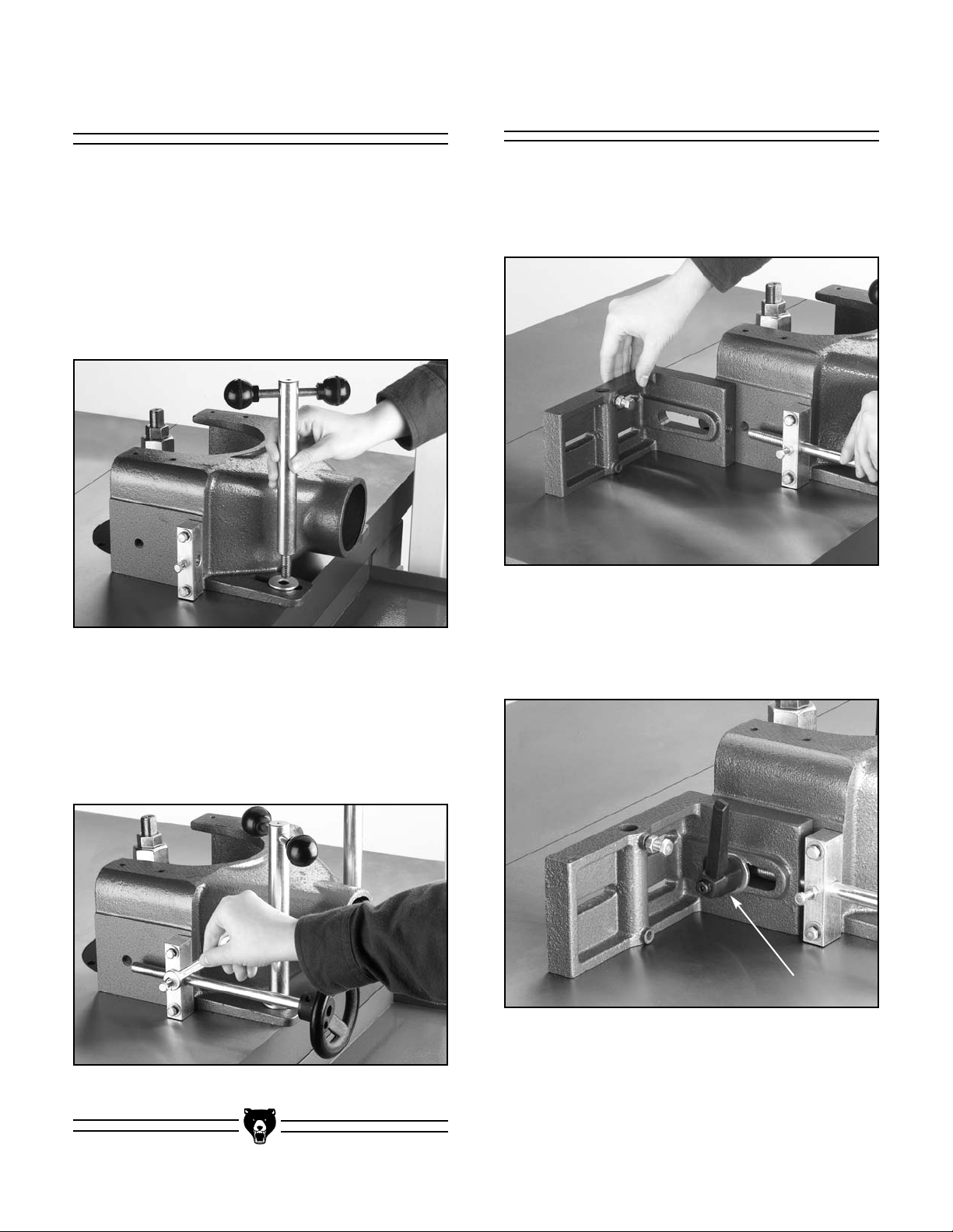
To mount the cutter guard to the table:
1. Place the guard over the threaded holes on
the table.
2. Insert the shaft guide into the guard as
shown in Figure 12, and thread the shaft
guide clockwise to secure the guard to the
table.
Figure 12. Inserting shaft guide into guard.
Insert the adjustment guide into the screw bracket. Line up the shaft groove shown in Figure 11
with the center bolt and screw the bolt into the
groove as shown in Figure 13. Do not completely tighten the bolt. This will allow the shaft to spin
without coming out.
To mount the fence brackets to the guard body:
1. Insert the adjustment shaft into the fence
bracket as shown in Figure 14.
Figure 14. Adjustment guide to fence bracket.
2. Insert the adjustment handle (Figure 15) into
the fence bracket, and thread it into the
guard body.
Figure 15. Adjustment handle.
Figure 13. Tightening bolt into shaft groove.
-14- G8621 Heavy-Duty Sliding Table Shaper
Page 17
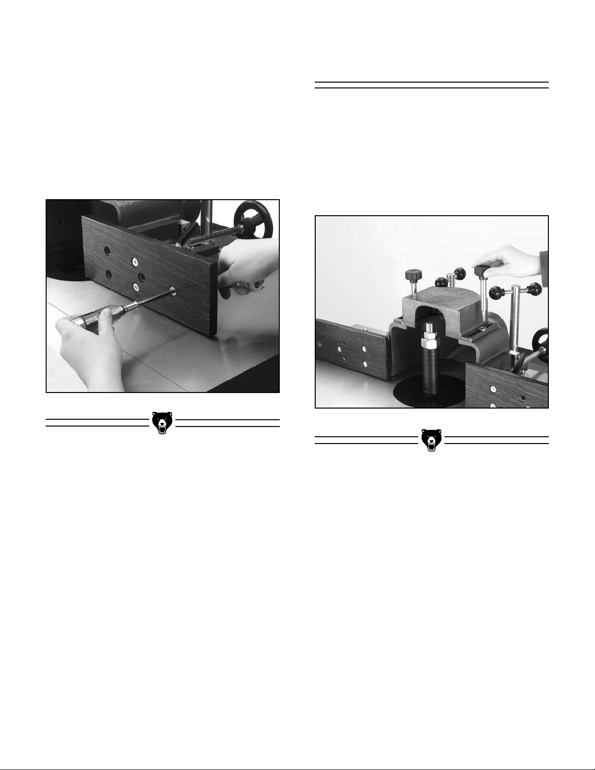
To install the wood facing:
1. Secure the wooden fence pieces (as shown
in Figure 16) with the
head screws, washers, and hex nuts provided.
5
⁄16''- 18 x 1'' Phillips
Guard Cover
®
To mount the guard cover:
2. If using your own wood faces, make sure the
countersunk holes in your fence material are
deep enough to keep the entire screw head
below the fence surface.
Figure 16. Attach wooden fence assembly.
1. Place the guard cover over the threaded
holes on top of the guard body as shown in
Figure 17.
2. Thread the knobs into the guard body and
secure the cover.
Figure 17. Guard cover.
G8621 Heavy-Duty Sliding Table Shaper -15-
Page 18
Hold-Downs Miter Assembly
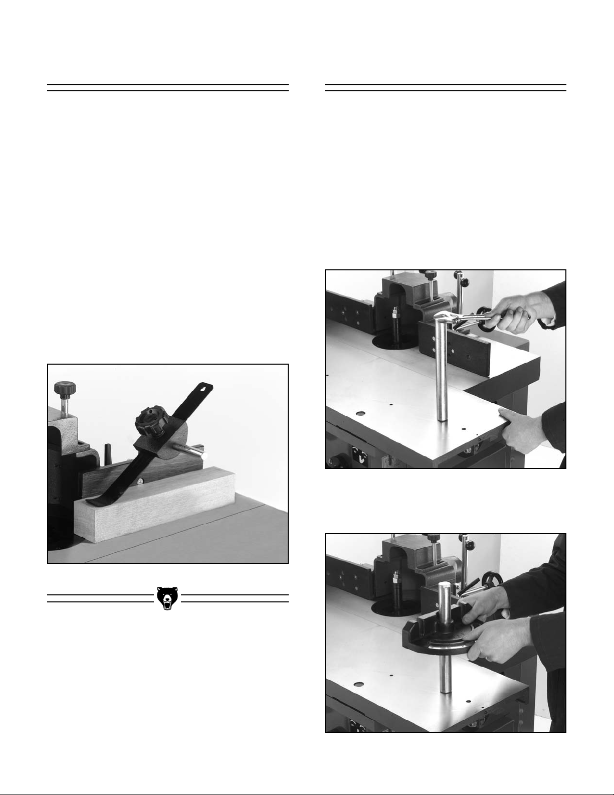
Hold-downs are used to hold the workpiece flat
and snug against table as shown in Figure 18. To
assemble the hold-downs:
1. Slide a hold-down plate into each of the cast
iron hold-down brackets.
2. Insert the bracket pole into the fence bracket
and hold-down bracket.
3. Partially screw the handle into the hold-down
brackets.
4. Position the hold-downs according to the
size of your workpiece.
5. Tighten the handles to secure the holddowns.
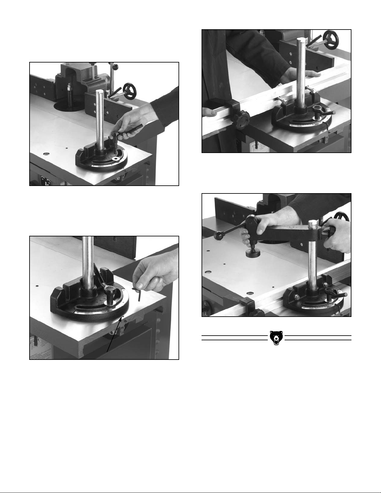
The miter gauge for the Model G8621 features a
clamp and special fence. The miter gauge
assembly can be mounted on either end of the
table, depending on the type of desired cut or cutting direction. To mount the miter gauge and its
fence:
1. Locate the threaded holes on either side of
the table.
2. Install the push shaft as shown in Figure 19.
Figure 19. Installing the push shaft.
3. Now, slide the miter gauge down the push
shaft as in Figure 20.
Figure 18. Hold-down on workpiece.
Figure 20. Installing the miter gauge.
-16- G8621 Heavy-Duty Sliding Table Shaper
Page 19
4. With the provided washer, thread the ratchet
handle through the miter gauge and into the
table as shown in Figure 21.
Figure 21. Installing the ratchet handle.
5. Insert the the miter gauge pointer shown in
Figure 22, but do not tighten the nearby
setscrew at this time.
Figure 23. Installing the miter fence.
7. Slide the clamping unit onto the push shaft
as shown in Figure 24.
Figure 24. Installing the clamping unit.
Figure 22. Installing the pointer.
6. Place flat washers on the miter fence hex
bolts, then start the special nuts onto the
ends. Slide the special nuts into the groove
of the fence. The end piece for the fence
works with the same special nut and hex bolt
system. When these have all been installed
on the miter fence, it is time to install the
fence onto the miter gauge as in Figure 23.
G8621 Heavy-Duty Sliding Table Shaper -17-
Page 20
SECTION 5: ADJUSTMENTS
Adjustment
Keep loose clothing
rolled up and out of the
way of machinery and
keep hair pulled back.
Disconnect power to the
machine when performing any adjustments or
maintenance. Failure to
do this may result in serious personal injury.
4. This process is easiest with the help of
Wear safety glasses during the entire adjustment
process. Failure to comply may result in serious
personal injury.
Setscrew
Figure 25. Inspecting pulley alignment.
another person. Loosen the four bolts that
attach the motor to the motor base. One person should slide the motor either up or down
while the other person measures the alignment of the motor pulley and the spindle pulley with a straightedge.
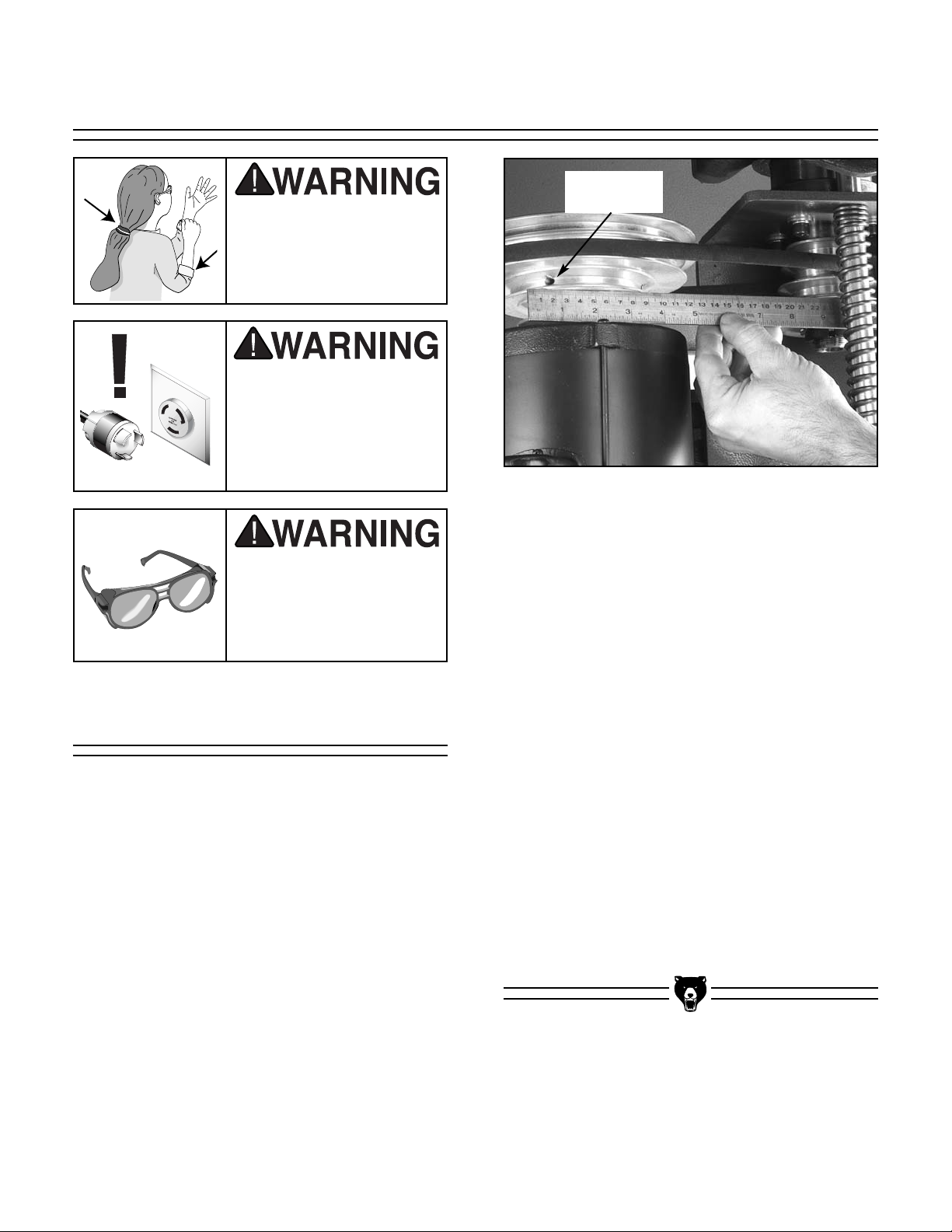
Pulleys & V-Belt
Improper pulley alignment sharply reduces the
effectiveness of power transmission and belt life
expectancy. To align the pulleys:
1. Remove the motor cover from the back of
the shaper cabinet to expose the motor and
pulleys.
2. Check the alignment with a straightedge. If
the pulleys are in alignment, the straightedge
should touch two sides of each pulley evenly as in Figure 25.
3. If the pulleys are parallel with each other, but
not in-line, the motor needs to be adjusted.
5. When the motor pulley and the spindle pulley
alignment are correct, tighten the motor to
the motor base.
6. Inspect your results. If satisfactory, doublecheck that the mounting bolts are tight.
7. You can also make small adjustments in the
motor pulley alignment by raising or lowering
it along the motor shaft. To do this, loosen
the two setscrews (one is shown in Figure
25) which are in the lowest groove of the
motor pulley and move the pulley into position. Tighten the setscrews when the alignment is satisfactory.
-18- G8621 Heavy-Duty Sliding Table Shaper
Page 21
V-Belt Tension
Speed Changes
You should be able to deflect the belt 1⁄4" with
moderate finger pressure. This may seem tight
compared to most other V-belts, but since the belt
is small and runs fast, this amount of tension is
necessary. The V-belt will slip if too loose, and
will squeal or cause vibration if too tight. Adjust
the tension if necessary. To adjust V-belt tension:
1. Make sure the pulleys are properly aligned.
2. Loosen the two motor mount plate bolts and
slide the motor left or right to modify the belt
tension. Keep the pulleys aligned.
3. Tighten the motor mount plate bolts, test the
tension, and check the pulleys.
4. Repeat steps 2-3 until tension is correct and
the pulleys are aligned.
Disconnect power to the
machine when performing any adjustments or
maintenance. Failure to
do this may result in serious personal injury.
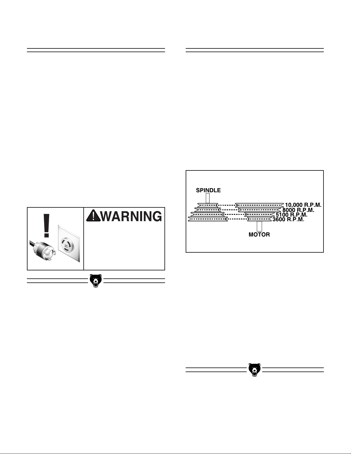
The Model G8621 Shaper is equipped with a Vbelt drive system that controls the speeds. To
change spindle speeds:
1. Unplug the machine.
2. Loosen the two motor plate bolts, and slide
the motor toward the spindle assembly. DO
NOT take the bolts out.
3. Select the desired speed. There are four
speeds: 3600 R.P.M., 5100 R.P.M., 8000
R.P.M., 10,000 R.P.M. Figure 26 shows the
belt positions for each available speed.
Figure 26. Spindle speed adjustment.
4. Align the belt along the appropriate pulley
grooves.
5. Slide the motor back into position and tighten the belt. When the belt is properly tensioned, there should be approximately
deflection in the center of the belt when you
press it with moderate pressure.
6. Tighten all the adjusting bolts.
7. Spin the pulley to ensure proper tracking.
G8621 Heavy-Duty Sliding Table Shaper -19-
1
⁄4" of
Page 22
Fence Adjustment
Aligning The Fences
The fence is a two-piece adjusting system. Each
fence is independently adjustable to compensate
for different cutting thicknesses and special shaping applications. Without any play, one turn of the
knob moves the split fence approximately
(.078"). To adjust the fence:
1. Loosen the fence lock handle.
2. Turn the fence adjustment knob until the
fence is set to the desired position.
3. Tighten the fence lock handle.
More detailed information concerning fence
adjustments is covered in the “Straight Shaping”
instructions.
5
⁄64"
The following procedure ensures that the fence is
parallel with itself and square with the table.
1. Check that the bolts through the wood facing
are tight on each side and are adequately
countersunk.
2. To align the wood facing, adjust one or both
fence halves so they are in close alignment.
Micro-adjust and check the alignment with a
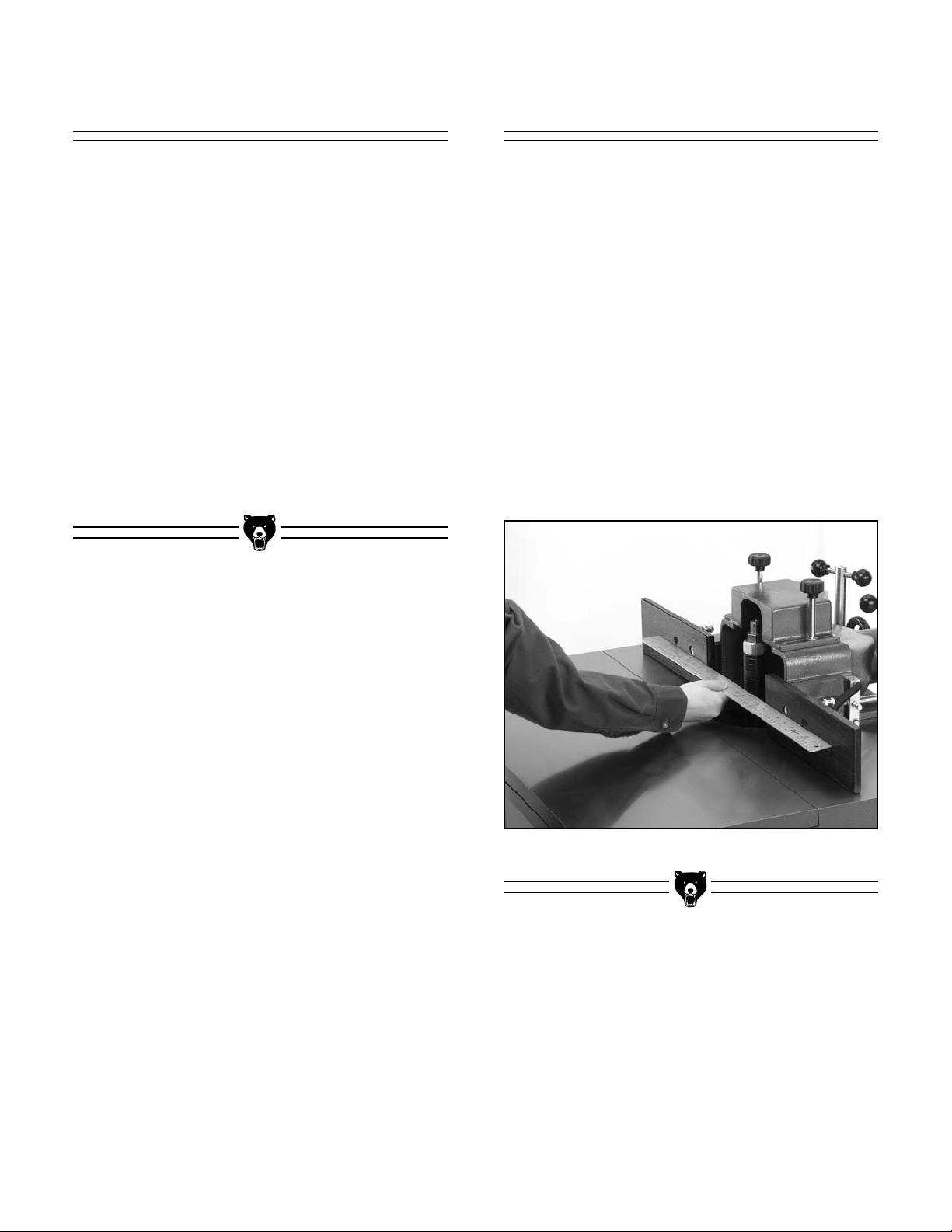
straightedge as shown in Figure 27.
3. If the wood fences are not parallel with each
other, shim the incorrect side with electrical
washers. Normal washers may work, but
electrical washers allow for fine adjustments.
Figure 27. Aligning fences with straightedge.
-20- G8621 Heavy-Duty Sliding Table Shaper
Page 23
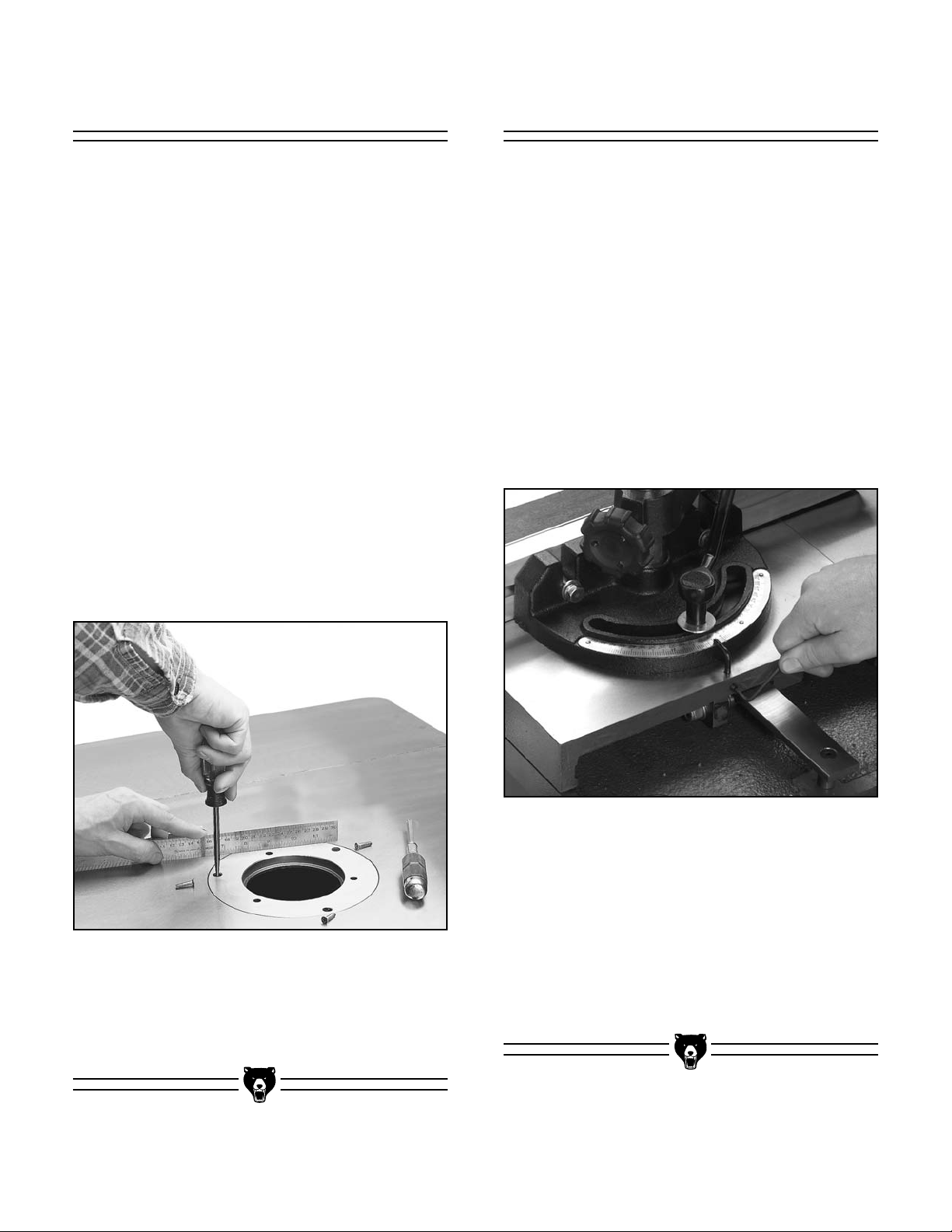
Table Inserts
Setting Miter Gauge
The Model G8621 is supplied with two inserts
which provide three possible opening diameters
in the shaper table surface. Use the smallest
opening that a particular cutter will allow. This
offers more support for the workpiece and
reduces the amount of chips that can fall into the
machine. The correct spindle opening also allows
any unused portion of the cutter to remain below
the table surface—increasing operator protection.
The cast iron table insert must be flush with the
top of the table. To adjust the insert:
1. Remove the three Phillips
hold the cast iron insert in place.
2. By using a straightedge and a screwdriver,
turn the barrel screws clockwise or counterclockwise to level the cast iron insert with the
table. See Figure 28.
®
head screws that
It is necessary to square the miter gauge each
time it is removed from the table. To do this:
1. Ensure that the fence halves are aligned and
that the miter assembly is correctly assembled.
2. Place one end of a framing or try square
flush with the infeed shaper fence.
3. Rotate the miter gauge so that it lines up
flush with the other end of the square.
4. Set the miter gauge pointer to 0° and tighten
the setscrew as shown in Figure 29.
Figure 29. Setting the miter gauge pointer.
5. Keeping the square flush with the infeed
fence and the miter fence, clamp it to the
table, and slide the table across the shaper.
The square should stay flush with both
Figure 28. Leveling table insert.
3. Inspect with the straightedge from both side-
to-side and front-to-back to ensure the insert
is flush with the table. Replace and secure
the Phillips
G8621 Heavy-Duty Sliding Table Shaper -21-
®
head screws.
infeed and outfeed fences during this movement. If this is the case, proceed to the next
section. If they do not stay flush or are not
square to the miter fence, repeat steps 1-4
until they are true.
Page 24
Test Run
Once assembly is complete and adjustments are
done to your satisfaction, you are ready to start
the machine.
DO NOT have a cutter installed when you test run
the shaper. Turn on the power supply at the main
panel. Press the ON button. Make sure that your
finger is poised on the OFF button, just in case
there is a problem. The shaper should run
smoothly with little or no vibration or rubbing noises. Strange or unnatural noises should be investigated and corrected before operating the
machine further.
If the shaper seems to be running correctly,
check the directional switch. The spindle should
be rotating in a counterclockwise direction when
the switch is in the FWD position. Run the Model
G8621 for a short time to ensure that the moving
parts are working properly with no excessive
vibration. If any problem develops, correct it
before attempting to use the machine.
Disconnect power to the
machine when performing any adjustments or
maintenance. Failure to
do this may result in serious personal injury.
Never use the Model G8621 for applications
other than those for which it was intended.
DO NOT overload the machine or use
excessive force when shaping materials.
Severe personal injury, damage to the
machine, or damage to your workpiece
could occur.
If you cannot locate the source of unusual noises,
immediately contact our service department for
help.
-22- G8621 Heavy-Duty Sliding Table Shaper
Page 25

SECTION 6: OPERATIONS
Rotation
Keep loose clothing
rolled up and out of the
way of machinery and
keep hair pulled back.
Disconnect power to the
machine when performing any adjustments or
maintenance. Failure to
do this may result in serious personal injury.
Wear safety glasses during all operations on the
shaper. Failure to comply may result in serious
personal injury.
Your shaper is equipped with a
FORWARD/REVERSE switch as shown in
Figure 30. In many instances, you will need to flip
the cutter over and reverse cutter rotation.
Whenever possible, mount the cutter so the
board is milled on the bottom side. This method
does a better job and is safer for the operator.
Always check the direction of cutter rotation before beginning any shaping operation, and always feed the work against the
direction of the cutter rotation.
Always wear a dust
mask when operating
the shaper. Using this
machine produces sawdust which may cause
allergic reactions or respiratory problems.
Figure 30. FORWARD/REVERSE switch.
NOTICE
The following section was designed to give
instructions on the basic operations of this
shaper. However, it is in no way comprehensive of every shaper application. There
are many different jigs that can be built to
increase safety, accuracy, and types of
cuts. WE STRONGLY RECOMMEND that
you read books, trade magazines, or get formal training to maximize the potential of
your shaper.
G8621 Heavy-Duty Sliding Table Shaper -23-
This machine was designed to be started
and stopped with the ON/OFF buttons—not
the reversing switch.
NOTICE
Page 26
Cutter Installation
Table Lock
Your shaper operates at speeds of 3600, 5100,
8000 and 10,000 R.P.M. 3
must be operated at the slowest speed.
Always use the largest spindle size possible, and
never use more than one bushing size to gain two
spindle sizes. ”Stacking” two cutter bushings to
decrease the inside diameter of the cutter will
cause the cutter to perform incorrectly when
placed under a load.
1. Unplug the shaper.
2. Place an appropriate spacer or collar at the
base of the spindle for support. Place the
cutter on the spindle, making sure the rotation is correct for your application.
3. Use spacers or collars to suit your particular
application, then place the spindle washer
under the nut. Screw on the nut and locknut.
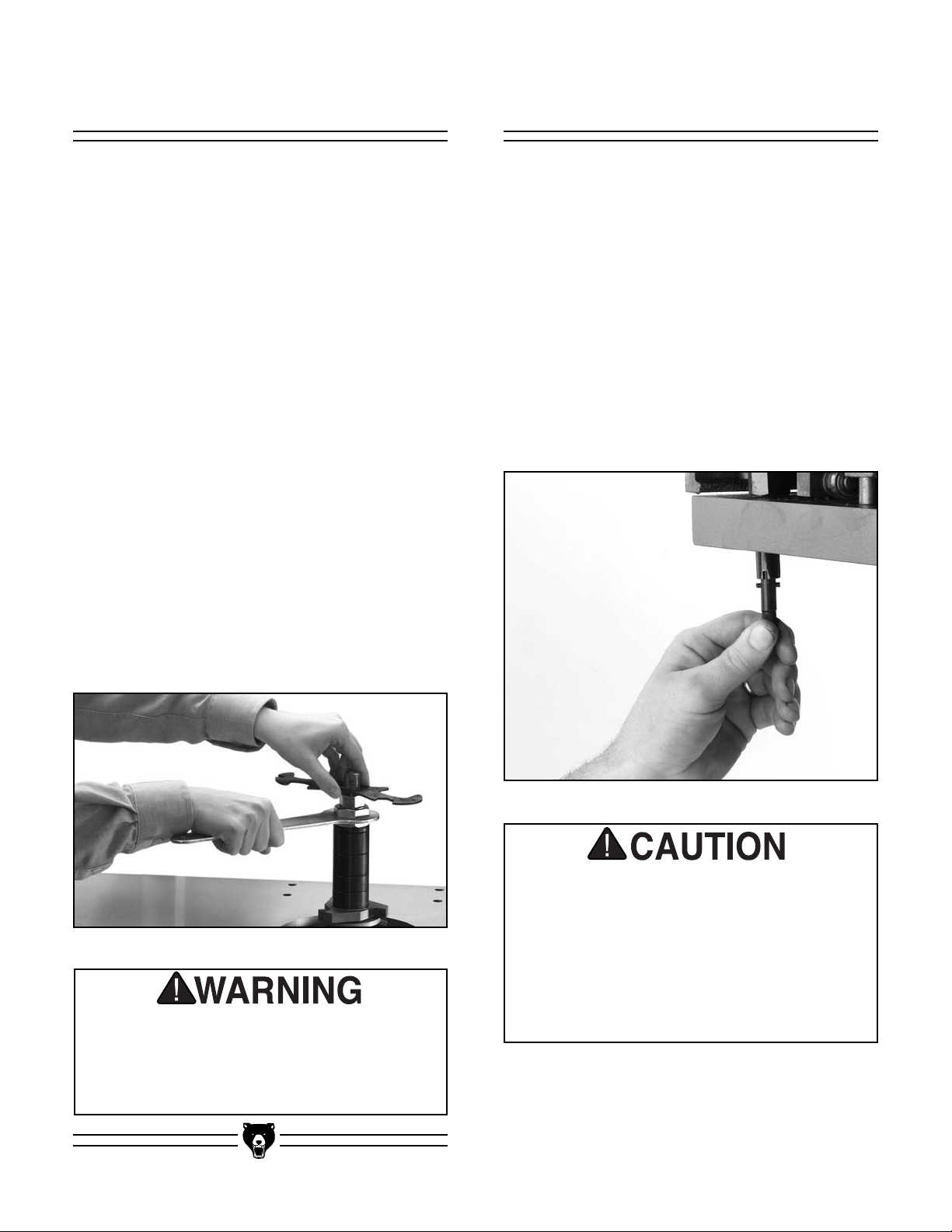
4. Tighten the nuts while holding the spindle
stationary. Use a wrench on the notches at
the top of the spindle for leverage as shown
in Figure 31.
1
⁄2" or larger cutters
The sliding table works with the clamping miter
gauge to allow you to secure your workpiece to
the table and make the cut by sliding the table.
This feature greatly increases operator safety
because it keeps hands away from the cutterhead.
When the sliding operation is not desired, the
table lock shown in Figure 32 will make the table
stationary. Simply pull the knurled shaft and twist
it so the cross pins slide into the largest slots in
the housing. If you want to unlock the table, pull
the shaft, twist it, and place the cross pins in the
smallest slot.
Figure 32. Table lock.
The sliding table makes it easy to feed the
work into the cutter at a faster rate than
would normally be used. Always feed the
Figure 31. Tightening spindle nuts.
Always use a spindle lock nut during operation. If this warning is ignored, the cutter
may fly off the spindle during use and
cause severe personal injury.
-24- G8621 Heavy-Duty Sliding Table Shaper
work slow and steady to avoid kickback
and to achieve smooth results with your
work. Although the miter assembly does
aid in safety, common sense should always
be used during every shaping operation.
Page 27
Spindle Height
To adjust the cutter height:
Straight Shaping
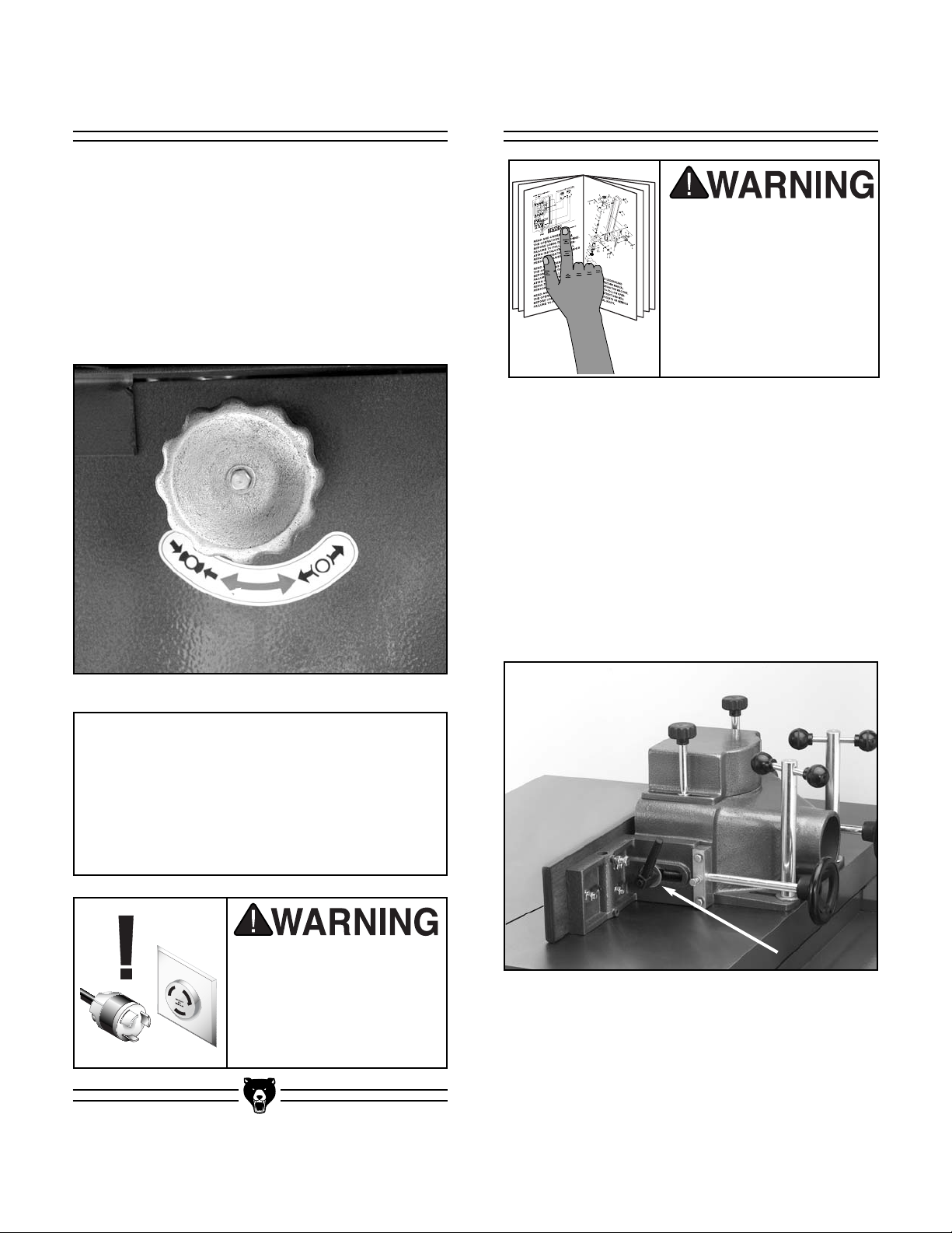
1. Loosen the spindle lock shown in Figure 33.
2. Move the spindle up or down with the hand-
wheel until the desired position is obtained.
3. Lock the spindle into position.
Read the entire manual
before making any cuts
with your shaper.
Serious personal injury
may result if safety or
operational information
is not understood or followed.
The fence assembly is a two-piece, independently adjustable system. When removing material
from the whole face of your workpiece, the outfeed fence can be adjusted to provide support
for the workpiece as it passes over the cutter.
The outfeed fence can also be set in-line for partial face removal.
If removing material from the whole face,
observe the following steps:
1. Loosen the locking handles shown in Figure
34 that hold the fences in place.
Figure 33. Location of spindle lock.
NOTICE
The lock knob keeps the spindle in a fixed
position during shaper operation. Do not
over-tighten the lock knob. A snug fit is all
that is needed to keep the spindle from
moving during shaper operation.
Disconnect power to the
machine when performing any adjustments or
maintenance. Failure to
do this may result in serious personal injury.
G8621 Heavy-Duty Sliding Table Shaper -25-
Figure 34. Location of fence locking handles.
2. Adjust the infeed fence by turning the adjust-
ment knobs until the workpiece contacts the
cutter in the desired location.
3. Lock the infeed fence in position with the
locking handle. Use a test piece to determine
the best setting.
Page 28
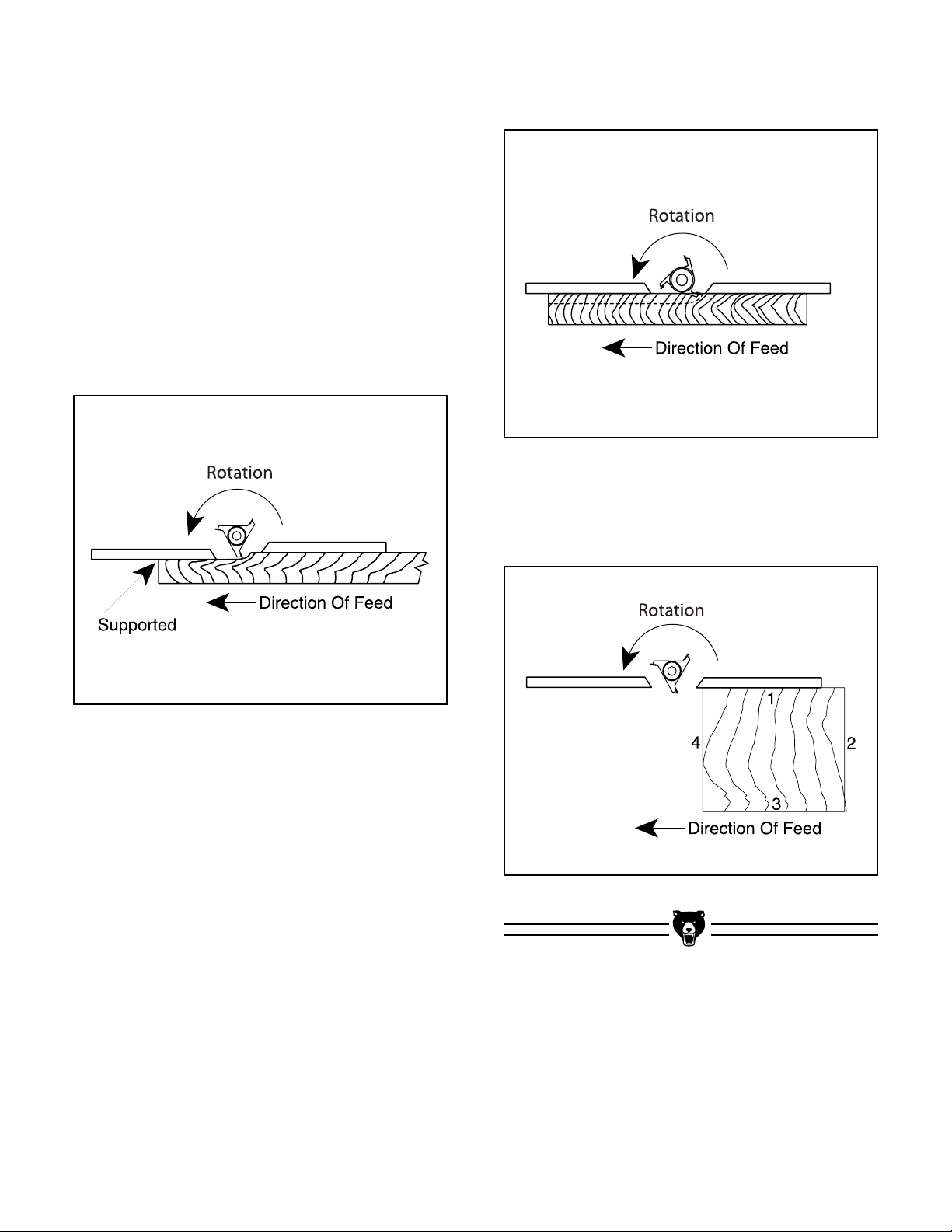
4. Loosen the mounting screws on the fence
faces and set the face ends to barely clear
the cutter. This allows the maximum support
possible for the workpiece while passing the
cutter. Remember to tighten the wood facing
before starting the shaper.
5. A test sample of the desired cut should be
advanced about 8'' then stopped.
6. Once the shaper is turned off and the cutter
has come to a complete stop, adjust the outfeed fence to support the new profiled edge.
See Figure 35.
4. Run a test piece through the shaper as
shown in Figure 36.
Figure 36. Fence adjustment for blind cuts.
5. Always cut the end grain first when putting
an edge around the perimeter of your workpiece. See Figure 37.
Figure 35. Fence adjusted to support workpiece.
If the face of the workpiece will only be partially removed, observe the following steps:
1. Adjust the infeed fence to approximately the
desired depth of cut. Lock the infeed fence in
place.
Figure 37. Sequence for multiple cuts.
2. Use a straightedge to adjust the outfeed
fence to the same plane as the infeed. Lock
the outfeed fence in place.
3. Set the right and left wood face ends so they
barely clear the cutter. This allows the maximum support possible for the workpiece
while passing the cutter. Remember to tighten down the wood facing before starting the
shaper.
-26- G8621 Heavy-Duty Sliding Table Shaper
Page 29
Rub Collars
Rub collars are used when shaping curved or
irregular workpieces, such as arched doors or
round table tops. Rub collars also limit the depth
of your cut.
There are two types of rub collars—solid and ballbearing. We recommend against the use of solid
rub collars. Grizzly carries an extensive line of
ball bearing rub collars designed for use with
Grizzly shapers. See the current catalog for listings.
Rub collars may be used in any of the following
positions:
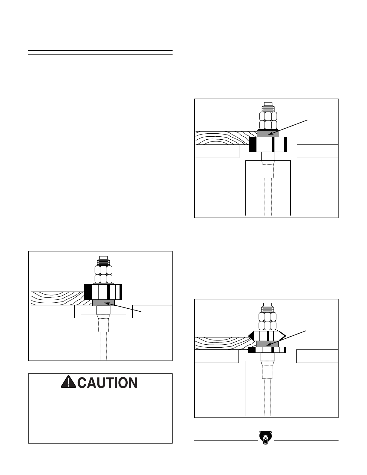
1. Rub collar below the cutter: When the rub
collar is used below the cutter as shown in
Figure 38, the progress of the cut can be
observed. However, any unintentional movement may lift the workpiece into the cutter,
damaging your work and creating a dangerous situation that may result in kickback. We
do not recommend using the rub collar below
the cutter.
2. Above the cutter: When the rub collar is
used above the cutter as seen in Figure 39,
the cut cannot be seen. This offers some
advantage: the stock is not affected by slight
variations in thickness and accidental lifting
will not damage the workpiece. If lifting
occurs, simply correct the mistake by repeating the operation.
Figure 39. Rub collar installed above cutter.
3. Between two cutters: Using a rub collar
between two cutters, as in Figure 40, has
the distinct advantage of performing two cuts
at once or eliminating the need to change
cutters for two different operations. Notice
that part of the edge is left uncut. The uncut
portion rides on the rub collar.
Figure 38. Rub collar installed below cutter.
Whenever the cutterhead is above the
workpiece, or you can see it spinning during use, you must take extreme caution to
keep your hands away from the cutterhead.
Failure to do so may cause serious personal injury.
G8621 Heavy-Duty Sliding Table Shaper -27-
Figure 40. Rub collar between two cutters.
Page 30
Pattern Work
2. Make the jig stable, using proven methods
and materials, and fasten the hand holds for
operator comfort and safety.
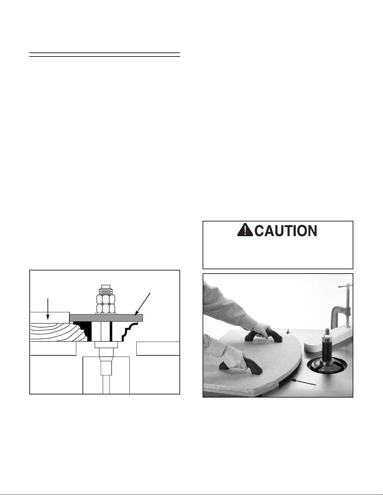
When using a pattern, the rub collar can be positioned either above, below or between cutters.
The pattern is usually used when the entire edge
is to be shaped or when many duplicate pieces
are needed. Pattern work is particularly useful
when rough cutting irregular or oversize pieces
and then shaping the edge in a simple two-step
operation. A pattern can be incorporated into a jig
by way of adding toggle clamps, hand holds or
other safety devices.
You have greater flexibility when choosing the
correct diameter rub collar for pattern work than
for non-pattern work. If you look at Figure 41, you
will notice that the position of the pattern determines the depth of cut. In other words, your pattern size is dependent upon the interrelationship
of the cutting circle, the desired amount of material removed, and the rub collar size. Changing
one or more of these will change the amount of
material removed. Planning ahead, you can most
effectively decide which rub collars are best suited for your application.
3. Secure your workpiece on the three sides
that will not be cut with toggle clamps, or fasten the workpiece to the jig with wood
screws.
4. Ensure that clamps and hidden screws do
not come into contact with the cutter.
5. Design your jig so that all cutting occurs
underneath the workpiece as shown in
Figure 42. Notice the operator is not
exposed to the cutting edge of the cutter!
6. Always consider the cutting circle and rub
collar diameter for the correct cutting depth
when designing your pattern.
7. Make sure the workpiece rests flat on the
table, not on the fixture.
Workpieces must be solid, stable, and
secured to the jig; or kickback may occur,
causing personal injury.
Pattern
Figure 41. Rub collar determines depth of cut.
When making a pattern jig here are a few things
to consider:
1. Build your jig from a material that will
smoothly follow the rub collar or fence.
Rub Collar
Workpiece fits here
Figure 42. Pattern jig for making curved pieces.
Irregular or freehand shaping takes a high degree
of skill and dexterity. The fence assembly is not
used during irregular shaping, so rub collars must
be used. Also, unless your jig is designed to
touch the rub collar before contacting the blade, a
starting fixture must be used to begin your cut.
-28- G8621 Heavy-Duty Sliding Table Shaper
Page 31
About starting fixtures:
The purpose of the starting fixture is to support
the workpiece during the beginning of the cut.
The workpiece is typically placed in the starting
position using the starting fixture for support,
Then swung into the cutter while holding the
workpiece firmly against the starting fixture. After
the cut has been started, the work is swung away
from the starting fixture and is supported only by
the rub collar. Always feed against the rotation
of the cutter and do not start cuts at corners.
To use your pattern jig:
Miter Assembly
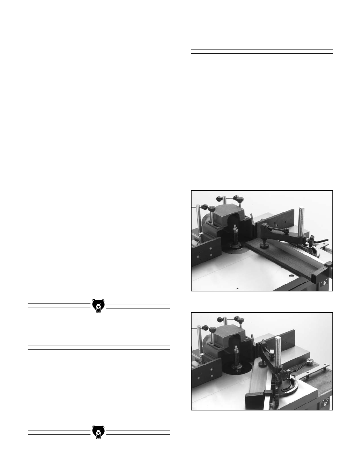
When the workpiece is clamped to the table using
the miter assembly, crosscuts can be made with
a much greater degree of safety. The miter gauge
can be adjusted to 60° in both directions. Figure
43 shows the miter gauge set to 0° and Figure 44
shows it at 45°. To adjust the miter fence:
1. Loosen the miter gauge with the adjustment
handle.
1. Remove the fence assembly. Choose the
appropriate cutter and rub collar for your
application and lock them in place. Secure
your workpiece to the pattern jig.
2. Check cutter rotation, and adjust the spindle
height to align the cutter to your workpiece.
Clamp a starting fixture to the table surface,
using the location that best supports your
work.
3. If everything is correct and the cutter is tight.
Turn the shaper on.
4. Place your jig/workpiece against the starting
fixture. Using firm pressure, pivot the workpiece into the cutter and make sure the jig is
touching the rub collar. Keep your jig in contact with the rub collar and slowly follow the
pattern, moving against the cutter rotation.
2. Assuming that you have performed the steps
in the “Setting Miter Gauge” instructions, turn
the miter gauge in the desired direction so
the pointer indicates the angle, and tighten
the miter gauge with the adjustment handle.
Figure 43. Miter gauge set to 0°
(fences opened for clarity).
Freehand Shaping
Freehand methods are one of the most dangerous operations performed on a shaper.
Although this machine is capable of performing
freehand operations, we do not recommend that
you attempt to do so. If you MUST perform freehand operations, get formal training and read a
book that details freehand operations, their inherent dangers, and ways to avoid those dangers!
G8621 Heavy-Duty Sliding Table Shaper -29-
Figure 44. Miter gauge set to 45°
(fences opened for clarity).
Page 32
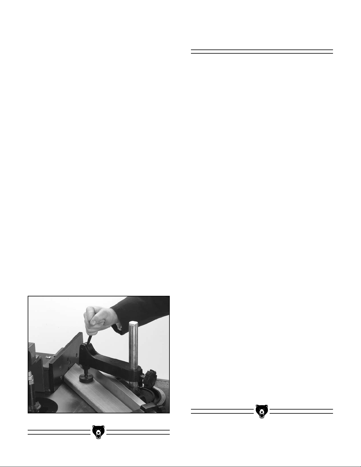
The miter fence can be adjusted by loosening
the two bolts that hold it to the miter gauge and
then sliding it in the desired direction.
Shaper Accessories
The support fence slides up and down the miter
fence and can be locked to hold the back of the
workpiece in place.
The miter clamp holds the workpiece firm
against the table and keeps it in position against
all of the associated fences.
To use the miter assembly:
1. Determine the angle of cut and set the miter
gauge to that angle, without tightening it yet.
(The angle of the miter gauge should be
determined by the angle of the workpiece
you are about to shape.) Lock the miter
gauge in place.
2. Move the infeed and outfeed fences out of
the way. Hold the workpiece flush against
the miter fence and slide the workpiece and
table toward the cutter. Line the workpiece
up with the cutter.
3. Slide the support fence to the back of the
workpiece and lock in place.
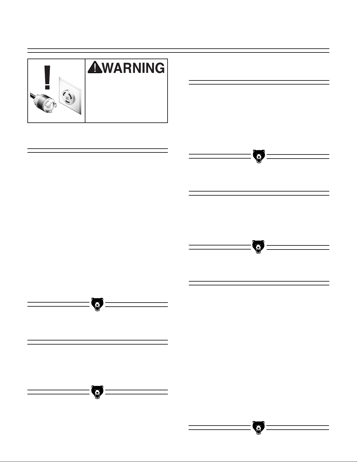
4. Clamp the workpiece to the table with the
miter clamp as shown in Figure 45.
5. The workpiece is now ready for the cut.
There are many accessories that can be built or
purchased to increase the safety of the operator.
Many experienced shaper users regularly use
proven shop-made fences and safety guards to
augment their shaping operations. In addition,
many production shops routinely use power feeders with their shapers to streamline their operations.
Here are some basic accessories and their uses:
• Zero Clearance Fence — A shop-made
fence with an opening only as large as the
cutter, so that only the part of the cutter
being used is exposed.
• Box Fence — A shop-made box that com-
pletely surrounds the cutter. A one-piece
fence is attached that allows only the thickness of the board to pass underneath, thereby completely shielding the operator from
exposure to the spinning cutter. A clear plexiglass window on top of the box allows the
operator to view the workpiece during cutting.
• Power Feeder — A motorized unit that can
be clamped or permanently mounted to the
table of a shaper. A power feeder pulls the
workpiece through the cut, reducing the risk
of operator contact with the spinning cutter
and reducing any injuries due to kickback.
Because of the steady feed rate, power feeders can also produce cleaner, more consistent cuts. Check the current Grizzly catalog
for available power feeders.
Because of the wide range of fences and guards
that can be built in the shop, explaining their construction is beyond the scope of this manual. We
strongly recommend that you read shaper books,
trade magazines, or get formal training to learn
more about these.
Figure 45. Locking down the miter clamp.
-30- G8621 Heavy-Duty Sliding Table Shaper
Page 33
SECTION 7: MAINTENANCE
Disconnect power to the
machine when performing any adjustments or
maintenance. Failure to
do this may result in serious personal injury.
General
Regular periodic maintenance on your Model
G8621 Shaper ensures its optimum performance.
Make a habit of inspecting your shaper each time
you use it.
Lubrication
The only parts on this machine that require periodic lubrication are the ways where the cartridge
slide rides on the elevation housing and where
the worm gear and bushing are located. Use a
light grease or anti-seizing compound on the
ways and worm gear, and give the shaft mount a
shot of light oil.
V-Belt
Check for the following conditions and repair or
replace when necessary.
1. Loose mounting bolts.
2. Worn switch.
3. Worn or damaged cords and plugs.
4. Damaged V-belt.
5. Any other condition that could hamper the
safe operation of this machine.
Table
Tables can be kept rust-free with regular applications of products like Boeshield
term storage you may want to consider products
like Kleen Bore's Rust Guardit™.
®
T-9. For long
Avoid getting grease or oil on the V-belt or pulleys. Check the V-belt, as part of a monthly
inspection for proper tension and belt condition.
Cracking and glazing could result in belt failure.
Replace the belt if such conditions appear.
Schedule
Regularly blow out air vents with compressed air
and keep the exhaust port clear. Always wear a
dust mask during this operation.
For every 1 hour of use, clean and wipe down
with Boeshield™ T-9:
• Table and miter gauge slide
• Fence faces
For every 5 hours of use, clean and oil:
• Spindle column and cartridge
• Offset adjustment mechanisms on fence
• All worm drive and other gears
Once a year, replace the V-belt.
G8621 Heavy-Duty Sliding Table Shaper -31-
Page 34
capacitor.Failureto do so will
leadtoasevereshockhazard.
position.Thiswilldischargethe
stillretaina chargeevenwiththe
Reversingswitchtotheforward
power disconnected.Turn the
injuryordeath.
The motorstartingcapacitorcan
beforeperformingany electrical
service.Failureto do thiswill
resultinashockhazardleadingto
Disconnectpowerfrommachine
OFF
LIGHT
ON
3
1
13
5
CONTACTORS
14
FOR/REV
RESET
POWER
6
ON
TERMINAL
STRIP
TERMINAL
4
2
STRIP
4
2
© 1998 Grizzly Industrial, Inc.
6
SWITCH
14
REVERSING
13
5
3
INDICATOR
REVERSE
LIGHT
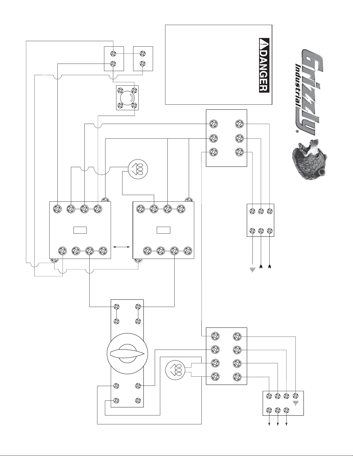
WIRE DIAGRAM
G8621 SHAPER
1
220 VOLT
SOURCE
TERMINAL
STRIP
MOTOR TERM.
-32- G8621 Heavy-Duty Sliding Table Shaper
Page 35
SECTION 8: CLOSURE
The following pages contain general machine
data, parts diagrams/lists, troubleshooting guide
and Warranty/Return information for your Model
G8621 Shaper.
If you need parts or help in assembling your
machine, or if you need operational information,
we encourage you to call our Service
Department. Our trained service technicians will
be glad to help you.
If you have comments dealing specifically with
this manual, please write to our Bellingham,
Washington location using the address in the
General Information section. The specifications,
drawings, and photographs illustrated in this
manual represent the Model G8621 as supplied
when the manual was prepared. However, due to
Grizzly’s policy of continuous improvement,
changes may be made at any time with no obligation on the part of Grizzly. Whenever possible,
though, we send manual updates to all owners of
a particular tool or machine. Should you receive
one, add the new information to this manual and
keep it for reference.
We recommend you keep a copy of our current
catalog for complete information regarding
Grizzly's warranty and return policy. If you need
additional technical information relating to this
machine, or if you need general assistance or
replacement parts, please contact the Service
Department listed in the Introduction section.
Additional information sources are necessary to
realize the full potential of this machine. Trade
journals, woodworking magazines and your local
library are good places to start.
The Model G8621 was specifically
designed for wood shaping operations
only. DO NOT MODIFY AND/OR USE THIS
MACHINE FOR ANY OTHER PURPOSE.
Modifications or improper use of this tool
will void the warranty. If you are confused
about any aspect of this machine, DO NOT
use it until all your questions have been
answered, or serious personal injury may
occur.
We have included some important safety measures that are essential to this machine’s operation. While most safety measures are generally
universal, Grizzly reminds you that each workshop is different and safety rules should be considered as they apply to your specific situation.
Operating this equipment has the potential
for flying debris to cause eye injury. Always
wear safety glasses or goggles when operating equipment. Everyday glasses or reading glasses only have impact resistant lenses, they are not safety glasses. Be certain
the safety glasses you wear meet the appropriate standards of the American National
Standards Institute (ANSI).
Like all power tools, there is danger associated with the Model G8621 Shaper.
Accidents are frequently caused by lack of
familiarity or failure to pay attention. Use
this tool with respect and caution to lessen
the possibility of operator injury. If normal
safety precautions are overlooked or
ignored, serious personal injury may occur.
G8621 Heavy-Duty Sliding Table Shaper -33-
Page 36

MACHINE DATA
SHEET
Customer Service #: (570) 546-9663 • To Order Call: (800) 523-4777 • Fax #: (800) 438-5901
GRIZZLY MODEL G8621 HEAVY-DUTY
SLIDING TABLE SHAPER
Design Type...................................................................................................... Floor Model
Overall Dimensions:
Fixed Table ..............................................................................................35
Sliding Table..............................................................................................35
Height (Includes Fence) ........................................................................................45
Height from Table To Floor ..................................................................................34
Length....................................................................................................................34
Width......................................................................................................................35
Width w/ table extended ........................................................................................56
Table Fence Length ..............................................................................................39
Crate Size ..................................................................................39" L x 31" W x 44" H
Footprint ..................................................................................................25
Shipping Weight ................................................................................................720 lbs.
Capacities:
Spindle Sizes ..............................................................................................
Spindle Lengths ..................................................................................................6'' - 7''
Spindle Capacity Under Nut ..................................................................4
Spindle Travel..........................................................................................................3
Dust Port ....................................................................................................................4"
Table Counter-bore ............................................................................................7'' x
Max. Cutter Diameter ..............................................................................................5
Spindle Speeds ........................................................3600, 5100, 8000, 10000 R.P.M.
Sliding Table Travel ..............................................................................................21
Construction:
Table ..................................................................................................Ground Cast Iron
Fence Assembly ............................Cast Iron ⁄ Wood; Independently Micro Adjustable
Miter Fence ....................................................................................Extruded Aluminum
Body Assembly ..............................................................................................Cast Iron
Cabinet ....................................................................................................Formed Steel
Motor:
Type ............................................................................TEFC Capacitor-Start Induction
Horsepower..........................................................................................................5 H.P.
Phase ⁄ Voltage ............................................................................Single Phase ⁄ 220 V
Switch..............Push Button ON/OFF, Emergency Stop; Lever for Forward / Reverse
Amps ......................................................................................................................25 A
Cycle ⁄ R.P.M.............................................................................60 Hertz ⁄ 3450 R.P.M.
Bearings ............................................................Shielded & Lubricated Ball Bearings
Features:
..................................................................................Lever Actuated Stock Hold-down
..................................................................Miter Angle Adjustable 60˚ Left to 60˚ Right
..................................................................................Miter fence adjustable stop block
..........................................................................4 Spring Steel Hold-down Assemblies
..................Fence adjustments include built-in ratchets and knob-equipped adjusters
..............................................................................................................3 Table Inserts
................................................................................Spindles include spacers and nuts
........................................................................Spindle height scale in inches and mm
................................Sliding table rides on eight shielded and lubricated ball bearings
Specifications, while deemed accurate, are not guaranteed.
1
⁄2'' x 147⁄8"
1
⁄2" x 131⁄4"
1
⁄2" x 263⁄4"
3
⁄4'', 1'', 11⁄4''
1
⁄4'', 45⁄8'', 51⁄8''
1
⁄2''
3
⁄4''
3
⁄4''
1
⁄2''
1
⁄2''
1
⁄2"
1
⁄4"
5
⁄8''
7
⁄8''
7
⁄8"
-34-
G8621 Heavy-Duty Sliding Table Shaper
Page 37
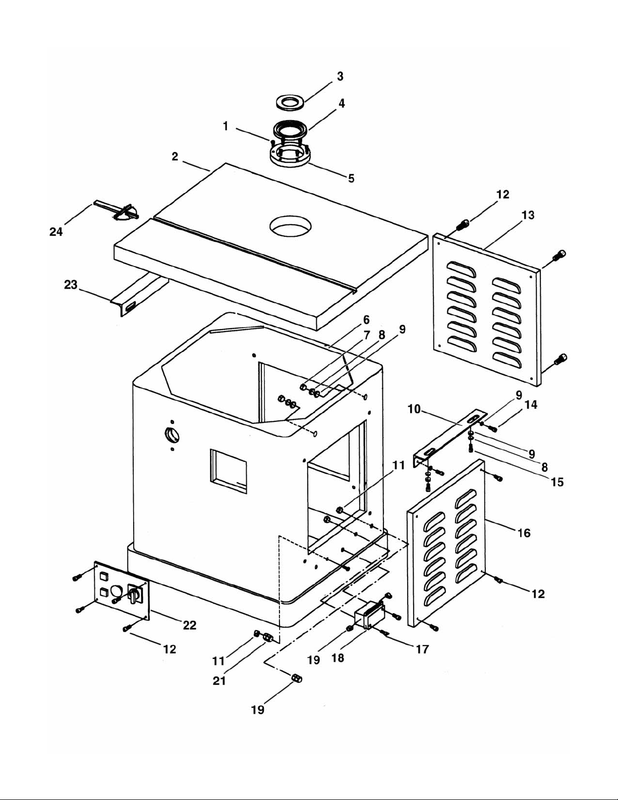
G8621 Heavy-Duty Sliding Table Shaper -35-
Page 38
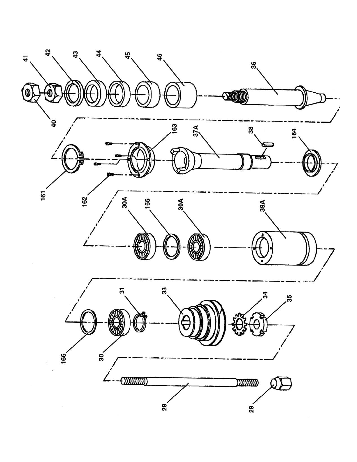
-36- G8621 Heavy-Duty Sliding Table Shaper
Page 39
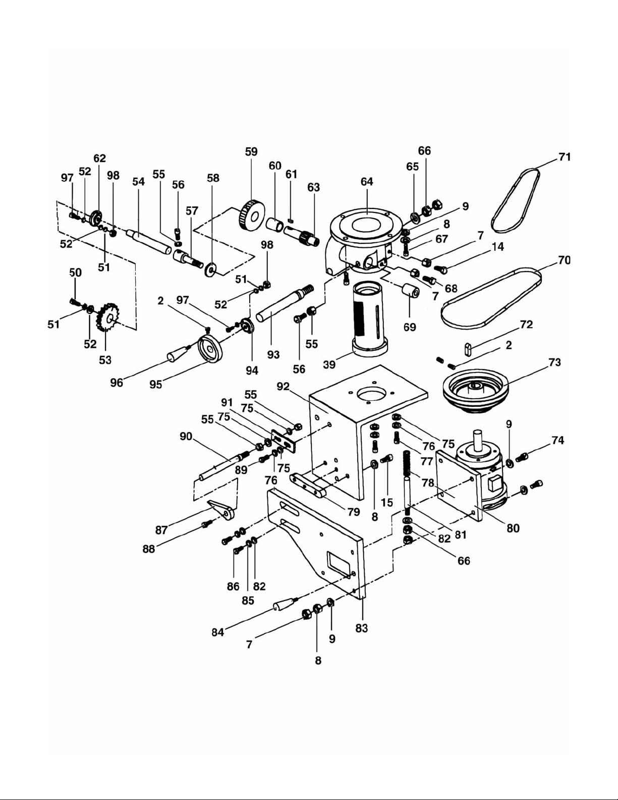
G8621 Heavy-Duty Sliding Table Shaper -37-
Page 40
-38- G8621 Heavy-Duty Sliding Table Shaper
Page 41
G8621 Heavy-Duty Sliding Table Shaper -39-
Page 42
REF PART # DESCRIPTION
001 PSS23 S
ET SCREW 5/16"-24 X 5/8"
003 P5912Z003 INSERT (SMALL)
004 P5912Z004 INSERT (MID)
005 P5912Z005 INSERT (BIG)
006 P5912Z006 STAND ASSY
007 PN08 HEX NUT
008 PLW04 LOCK WASHER
009 PW02 WASHER
3
/8"-16
3
/8"
3
/8"
010 P5912Z010 TABLE BRACE (R)
011 PN07 HEX NUT 10-24
012 PS12 PHLP HD SCR
013 P5912Z013
DUST DOOR
1
/4"-20 X 5/8"
014 PB24 BOLT HEX HD 3/8"-16X11/4"
015 PB21 BOLT HEX HD
3
/8"-16X13/4"
016 P5912Z016 COVER MOTOR
017 PS08 SCREW RD HD10-24 X
3
/4"
018 P5912Z018 ELECTRICAL BOX ASSY
019 P5912Z019 CONNECTOR
021 P5912Z021 CONNECTOR
022 P5912Z022 ELECTRICAL BOX ASSY
023 P5912Z023 TABLE BRACE (L)
024 P5912Z024 MITER GAUGE
028 P5912Z028 BOLT
029 P5912Z029 NUT LOCK
030 P6008ZZ BEARING 6008ZZ-K
031 P5912Z031 SNAP RING C40
032 P5912Z032 SNAP RING R80
033 P5912Z033 PULLEY SPINDLE
034 P5912Z034 WASHER
035 P5912Z035 NUT LOCK
036 P5912Z036 SPINDLE 1
1
/4"
037 P5912Z037 SPINDLE CARTRIDGE
038 P5912Z038 KEY 7MM
039 P5912Z039 QUILL
040 PN09-1 SPINDLE NUT 5
/8" (LH)
041 PN03 HEX NUT 3/4" (RH)
042 P5912Z042 COLLAR 1
043 P5912Z043 COLLAR 1
044 P5912Z044 COLLAR 1
045 P5912Z045 COLLAR 1
046 P5912Z046 COLLAR 1
050 PB02 BOLT HEX HD
051 PLW02 LOCK WASHER
052 PW06 WASHER
1
/4" X 1/4" 1PC
1
/4" X 3/8" 1PC
1
/4" X 1/2" 2PC
1
/4" X 3/4" 2PC
1
/4" X 1” 2PC
1
/4"-20 X 5/8"
1
1
/4"
/4"
REF PART # DESCRIPTION
053 P5912Z053 HANDWHEEL
054 P5912Z054 BAR LOCK
055 PN02 HEX NUT
056 PB03 HEX HD BOLT
5
/16"-18
5
/16"-18 X 1"
057 P5912Z057 SCREW LOCK
058 P5912Z058 WASHER GEAR
059 P5912Z059 GEAR
060 P5912Z060 COLLAR
061 P5912Z061 KEY 3MM
062 P5912Z062 BASE GEAR SHAFT
063 P5912Z063 SHAFT GEAR
064 P5912Z064 BASE SPINDLE
065 PW01 WASHER
066 PN06 HEX NUT
067 PSB19 CAP SCREW
1
/2"
1
/2"
3
/8"-16 X 11/4"
068 P5912Z068 SCREW
069 P5912Z069 COLLAR
070 PVA30 V-BELT A-30 4L300
071 PVA28 V-BELT A-28 4L280
072 P5912Z072 KEY 8MM
073 P5912Z073 PULLEY MOTOR
074 PB16 HEX HD BOLT
075 PW07 WASHER
076 PLW01 LOCK WASHER
077 PSB03 CAP SCR
3
/8"-16X 11/2"
5
/16"
5
5
/16"-18 X 1"
/16"
078 P5912Z078 SPRING
079 P5912Z079 KEY
080 P5912Z080 MOTOR
081 P5912Z081 SHAFT SPRING
082 PW01 WASHER
1
/2"
083 P5912Z083 BASE MOTOR
084 P5912Z084 KNOB
085 PLW07 LOCK WASHER
086 PB39 HEX HD BOLT
1
/2"
1
/2"-12X 11/2"
087 P5912Z087 POINTER
088 PS06 SCREW 10-24 X
089 PB07 HEX HD BOLT
3
/8"
5
/16"-18X3/4"
090 P5912Z090 SHAFT GUIDE
091 P5912Z091 PLATE
092 P5912Z092 MOTOR PLATE
093 P5912Z093 SHAFT GEAR
094 P5912Z094 BASE GEAR SHAFT
095 P5912Z095 HANDWHEEL
096 P1023009 HANDLE
-40- G8621 Heavy-Duty Sliding Table Shaper
Page 43
REF PART # DESCRIPTION REF PART # DESCRIPTION
1
097 PB31 HEX HD BOLT
098 PN05 HEX NUT
1
/4"-20
/4"-20 X 1"
105 P5912Z105 RATCHET LOCK HANDLE
106 P5912Z106 BRACKET SCREW GUIDE
107 P5912Z107 SCREW GUIDE
108 P5912Z108 NUT
109 P5912Z109 SHAFT GUIDE
110 P5912Z110 BAR
111 P5912Z111 KNOB
112 PW07 WASHER
5
/16"
113 P5912Z113 PLATE GUARD
114 P5912Z114 SET SCREW CUP PT
1
/4"
115 P5912Z115 BRCKT ASSY FENCE RH
116 P5912Z116 FENCE WOODEN
117 P5912Z117 SCREW
118 P5912Z118 TENSION
119 P5912Z119 GUARD
120 P5912Z120 BAR
121 P5912Z121 RETAINER (L)
122A P5912Z122A
KNOB BOLT
126 P5912Z126 BRCKT ASSY FENCE LH
127 PB26 BOLT HEX HD
1
/4"-20X 11/2"
128 P5912Z128 RESET SWITCH
129 P5912Z129 REVERSE LIGHT
130 P5912Z130 HANDLE WHEEL
161 P5912Z161 SNAP RING C-50
162 PSB17M CAP SCREW M4-.7 X 10
163 P5912Z163 OUTER DUST COVER
164 P5912Z164 INNER DUST COVER
165 P5912Z165 ALTERNATING RING
166 P5912Z166 WAVY RING
201 P5912Z201 TABLE
202 P5912Z202 ECCENT PULLEY SHAFT
203 PR12M C-RING R35
204 P6202 BEARING 6202Z
205 P5912Z205 PULLEY
206 PLW01 LOCK WASHER
207 P5912Z207 PHLP HD SCRW
208 P5912Z208 CAP SCREW
209 PN06 HEX NUT
1
5
⁄16"
5
1
⁄2"-12 X 11⁄2"
⁄2"
⁄16" X 11⁄2"
210 PR39M C-RING C8
211 P5912Z211 SHAFT
212 P5912Z212 SPRING
213 PR05M C-RING C15
214 P5912Z214 PRESS WHEEL
215 P5912Z215 PRESS SHAFT
216 P5912Z216 PLASTIC NUT
217 P5912Z217 PRESS WOOD BASE
218 P5912Z218 HANDLE LOCK
219 P5912Z219 SPRING SHAFT & BASE
221 P5912Z221 FENCE
222 P5912Z222 PUSH SHAFT
223 P5912Z223 HANDLE LOCK
224 PLW07 LOCK WASHER
225 PW01 WASHER
1
⁄2"
226 P5912Z226 DEGREE TAG
227 PW02 WASHER
3
"
8
228 PLW04 LOCK WASHER
229 P5912Z229 PHLP SCREW
3
230 P5912Z230 COVER
231 P5912Z231 NUT
232 P5912Z232 GAUGE
233 P5912Z233 FINGER
234 P5912Z234 PHLP SCREW 10-24 X
235 P5912Z235 GLIDE TABLE
236 PR01M C RING C-10
237 P6900 BEARING 6900ZZ
238 P5912Z238 ECCENT PULLEY SHAFT
239 PSB32 CAP SCREW
1`
⁄4"-20 X 1⁄4"
240 P5912Z240 NUT
241 P5912Z241 BEARING BASE
242 P5912Z242 RESIST BASE
243 P5912Z243 TABLE FIX SHAFT
244 P5912Z244 SPRING
245 P5912Z245 FIX SPRING SHAFT
246 PRP02M ROLL PIN 3 X 16MM
247 P5912Z247 CAP SCREW
1
⁄4"-20 X 11⁄2"
248 P5912Z248 SPACER
249 P5912Z249 GUIDE ORBIT
250 P5912Z250
3
⁄8" KNOB
251 P5912Z251 PIVOT
319 P5912Z319 HOOD
400 P5912Z400 WARNING LABEL
401 PLABEL-10 GRIZZLY NAME PLATE
402 P86211002 PULLEY LABEL
403 P5912Z403 SPEED CHANGE LABEL
1
⁄2"
3
⁄8"
⁄8"- X 11⁄2"
1
⁄4"
G8621 Heavy-Duty Sliding Table Shaper -41-
Page 44

WARRANTY AND RETURNS
Grizzly Industrial, Inc. warrants every product it sells for a period of 1 year to the original purchaser from
the date of purchase. This warranty does not apply to defects due directly or indirectly to misuse, abuse,
negligence, accidents, repairs or alterations or lack of maintenance. This is Grizzly’s sole written warranty
and any and all warranties that may be implied by law, including any merchantability or fitness, for any particular purpose, are hereby limited to the duration of this written warranty. We do not warrant or represent
that the merchandise complies with the provisions of any law or acts unless the manufacturer so warrants.
In no event shall Grizzly’s liability under this warranty exceed the purchase price paid for the product and
any legal actions brought against Grizzly shall be tried in the State of Washington, County of Whatcom.
We shall in no event be liable for death, injuries to persons or property or for incidental, contingent, special, or consequential damages arising from the use of our products.
To take advantage of this warranty, contact us by mail or phone and give us all the details. We will then
issue you a “Return Number,’’ which must be clearly posted on the outside as well as the inside of the carton. We will not accept any item without this number. Proof of purchase must accompany the merchandise.
The manufacturers reserve the right to change specifications at any time because they constantly strive to
achieve better quality equipment. We make every effort to ensure that our products meet high quality and
durability standards and we hope you never need to use this warranty.
Please feel free to write or call us if you have any questions about the machine or the manual.
Thank you again for your business and continued support. We hope to serve you again soon.
-42- G8621 Heavy-Duty Sliding Table Shaper
Page 45

WARRANTY CARD
Name ____________________________________________________________________________________
Street ____________________________________________________________________________________
City ______________________________________________________________State________Zip_________
Phone Number_______________________E-Mail_______________________FAX________________________
MODEL #G8621 Heavy-Duty Sliding Table Shaper Order_________________________________________
The following information is given on a voluntary basis. It will be used for marketing purposes to help us develop better products and services. Of
course, all information is strictly confidential.
1. How did you learn about us?
___Advertisement ___Friend
___Catalog ___World Wide Web
___Other__________________________________________________
2. Which of the following magazines do you subscribe to.
___American Woodworker ___Practical Homeowner
___Cabinetmaker ___Shop Notes
___Family Handyman ___Today’s Homeowner
___Fine Homebuilding ___WOOD
___Fine Woodworking ___Wooden Boat
___Home Handyman ___Woodshop News
___Journal of Light Construction ___Woodsmith
___Old House Journal ___Woodwork
___Popular Mechanics ___Woodworker
___Popular Science ___Woodworker’s Journal
___Popular Woodworking ___Workbench
___Other__________________________________________________
3. Which of the following woodworking/remodeling shows do you watch?
___Backyard America ___The New Yankee Workshop
___Home Time ___This Old House
___The American Woodworker ___Woodwright’s Shop
___Other__________________________________________________
4. What is your annual household income?
___$20,000-$29,999 ___$60,000-$69,999
___$30,000-$39,999 ___$70,000-$79,999
___$40,000-$49,999 ___$80,000-$89,999
___$50,000-$59,999 ___$90,000 +
5. What is your age group?
___20-29 ___50-59
___30-39 ___60-69
___40-49 ___70 +
6. How long have you been a woodworker?
___0 - 2 Years ___8 - 20 Years
___2 - 8 Years ___20+ Years
7. How would you rank your woodworking skills?
___Simple ___Advanced
___Intermediate ___Master Craftsman
8. What stationary woodworking tools do you own? Check all that apply.
___Air Compressor ___Panel Saw
___Band Saw ___Planer
___Drill Press ___Power Feeder
___Drum Sander ___Radial Arm Saw
___Dust Collector ___Shaper
___Horizontal Boring Machine ___Spindle Sander
___Jointer ___Table Saw
___Lathe ___Vacuum Veneer Press
___Mortiser ___Wide Belt Sander
___Other__________________________________________________
9. How many of your woodworking machines are Grizzly? _____________
10. Which benchtop tools do you own? Check all that apply.
___1" x 42" Belt Sander ___6" - 8" Grinder
___5" - 8" Drill Press ___Mini Lathe
___8" Table Saw ___10" - 12" Thickness Planer
___8" - 10" Bandsaw ___Scroll Saw
___Disc/Belt Sander ___Spindle/Belt Sander
___Mini Jointer
___Other__________________________________________________
11. How many of the machines checked above are Grizzly? ____________
12. Which portable/hand held power tools do you own? Check all that apply.
___Belt Sander ___Orbital Sander
___Biscuit Joiner ___Palm Sander
___Circular Saw ___Portable Planer
___Detail Sander ___Saber Saw
___Drill/Driver ___Reciprocating Saw
___Miter Saw ___Router
___Other__________________________________________________
13. What machines/supplies would you like Grizzly Industrial to carry?
___12" Table Saw ___Radial Arm Saw
___12" Jointer ___Panel Saw
___Combination Planer/Jointer ___Brass Hardware
___Paint & Finishing Supplies ___Lumber
___Contractor’s Supplies
___Other__________________________________________________
14. What new accessories would you like Grizzly Industrial to carry?
___Builders Hardware ___Hand Tools
___Fasteners ___Wood Components
___Other__________________________________________________
15. What other companies do you purchase your tools and supplies from?
__________________________________________________________
__________________________________________________________
16. Do you think your purchase represents good value?
___Yes ___No
17. Would you recommend Grizzly Imports to a friend?
___Yes ___No
18. Would you allow us to use your name as a reference for Grizzly customers
in your area? Note: We never use names more than three times.
___Yes ___No
19. Comments:_______________________________________________
__________________________________________________________
__________________________________________________________
__________________________________________________________
__________________________________________________________
CUT ALONG DOTTED LINE
Page 46

FOLD ALONG DOTTED LINE
Place
Stamp
Here
GRIZZLY INDUSTRIAL, INC.
P.O. BOX 2069
BELLINGHAM, WA 98227-2069
FOLD ALONG DOTTED LINE
Send a Grizzly Catalog to a friend:
Name_______________________________
Street_______________________________
City______________State______Zip______
TAPE ALONG EDGES--PLEASE DO NOT STAPLE
Page 47

Page 48

"UY$IRECTAND3AVEWITH'RIZZLY®n4RUSTED0ROVENANDA'REAT6ALUE
6ISIT/UR7EBSITE4ODAY!ND$ISCOVER7HY
'RIZZLY
s 3%#52%/2$%2).'
s /2$%233()00%$7)4().(/523
s %-!),2%30/.3%7)4()./.%(/52
§
)S4HE)NDUSTRY,EADER
/2
#ALL4ODAY&OR!
&2%%
&ULL#OLOR#ATALOG
 Loading...