

Page 1

MODEL G0972
3" X 78" KNIFE-MAKING
GRINDER
OWNER'S MANUAL
(For models manufactured since 10/23)
COPYRIGHT © APRIL, 2024 BY GRIZZLY INDUSTRIAL, INC.
WARNING: NO PORTION OF THIS MANUAL MAY BE REPRODUCED IN ANY SHAPE
OR FORM WITHOUT THE WRITTEN APPROVAL OF GRIZZLY INDUSTRIAL, INC.
#CS23122 PRINTED IN CHINA
***Keep for Future Reference***
V1.0 4.24
Page 2
This manual provides critical safety instructions on the proper setup,
operation, maintenance, and service of this machine/tool. Save this
document, refer to it often, and use it to instruct other operators.
Failure to read, understand and follow the instructions in this manual
may result in fire or serious personal injury—including amputation,
electrocution, or death.
The owner of this machine/tool is solely responsible for its safe use.
This responsibility includes but is not limited to proper installation in
a safe environment, personnel training and usage authorization,
proper inspection and maintenance, manual availability and comprehension, application of safety devices, cutting/sanding/grinding tool
integrity, and the usage of personal protective equipment.
The manufacturer will not be held liable for injury or property damage
from negligence, improper training, machine modifications or misuse.
Some dust created by power sanding, sawing, grinding, drilling, and
other construction activities contains chemicals known to the State
of California to cause cancer, birth defects or other reproductive
harm. Some examples of these chemicals are:
• Lead from lead-based paints.
• Crystalline silica from bricks, cement and other masonry products.
• Arsenic and chromium from chemically-treated lumber.
Your risk from these exposures varies, depending on how often you
do this type of work. To reduce your exposure to these chemicals:
Work in a well ventilated area, and work with approved safety equipment, such as those dust masks that are specially designed to filter
out microscopic particles.
Page 3

Table of Contents
INTRODUCTION ............................................... 2
Contact Info
Manual Accuracy
Identification
Controls & Components
Machine Data Sheet
SECTION 1: SAFETY
Safety Instructions for Machinery
Additional Safety for Metal Belt Grinders
SECTION 2: POWER SUPPLY
SECTION 3: SETUP
Needed for Setup
Unpacking
Inventory
Cleanup
Site Considerations
Assembly
Anchoring to Floor
Test Run
SECTION 4: OPERATIONS
Operation Overview
Workpiece Inspection
Grinding Tips
Choosing Abrasive Belts .............................. 26
Changing Frame Tilt
Tracking Belt
Installing Contact Wheel
Grinding Attachment
Adjusting Table Tilt
Contact Wheel Grinding
Installing Platen Grinding Attachment
Adjusting Platen Tilt
Platen Grinding
Slack Belt Grinding
Installing Pipe Notching Attachments
Pipe Notching
................................................... 2
........................................... 2
................................................... 3
................................. 4
...................................... 7
....................................... 9
.................. 9
.....11
...................... 12
....................................... 14
......................................... 14
.................................................... 14
...................................................... 15
........................................................ 16
...................................... 17
..................................................... 18
....................................... 20
....................................................... 21
............................ 24
..................................... 24
................................... 25
................................................ 25
.................................... 26
................................................ 28
.................................... 29
....................................... 31
............................... 31
......... 32
..................................... 34
............................................ 34
...................................... 36
.......... 36
.............................................. 38
SECTION 5: ACCESSORIES
SECTION 6: MAINTENANCE
Schedule
Cleaning & Protecting
Emptying Spark Trap
Replacing Belts
Lubrication
SECTION 7: SERVICE
Troubleshooting
Adjusting Platen to Wheels
SECTION 8: WIRING
Wiring Safety Instructions
Wiring Diagram
Electrical Components
SECTION 9: PARTS
Main
Electrical Cabinet
Labels & Cosmetics
WARRANTY & RETURNS
...................................................... 41
.................................. 41
................................... 41
............................................ 42
................................................... 42
................................... 43
........................................... 43
...................................... 46
............................ 46
............................................ 47
................................. 48
....................................... 49
............................................................. 49
......................................... 51
..................................... 52
.............................. 53
......................... 40
......................... 41
.......................... 45
Page 4
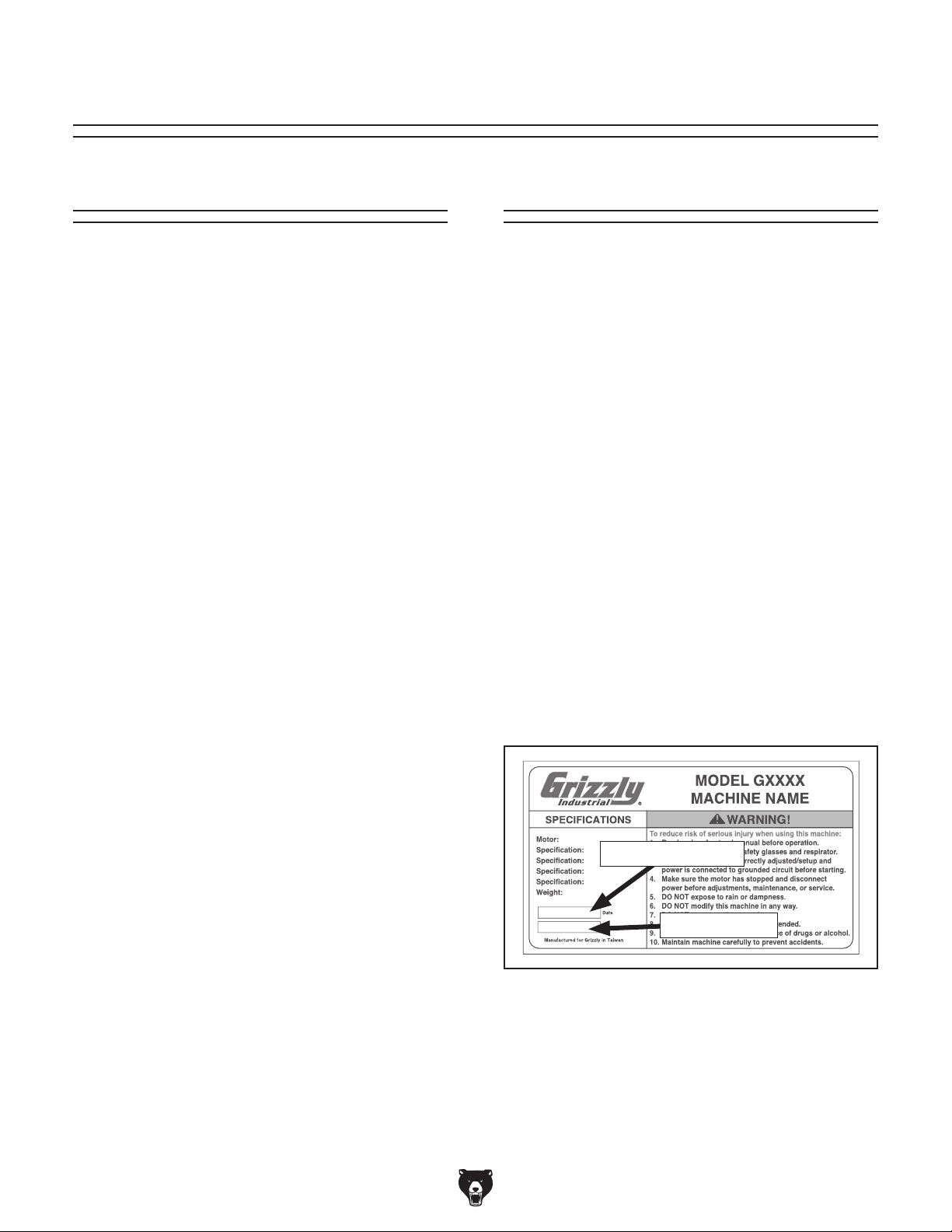
We stand behind our machines! If you have questions or need help, contact us with the information
below. Before contacting, make sure you get the
serial number
from the
machine ID label. This will help us help you faster.
We want your feedback on this manual. What did
you like about it? Where could it be improved?
Please take a few minutes to give us feedback.
Email: [email protected]
We are proud to provide a high-quality owner’s
manual with your new machine!
We
instructions, specifications, drawings, and photographs
in this manual. Sometimes we make mistakes, but
our policy of continuous improvement also means
that
you receive is
slightly different than shown in the manual
If you find this to be the case, and the difference
between the manual and machine leaves you
confused or unsure about something
check our
website for an updated version. W
current
manuals and
on our web-
site at
Alternatively, you can call our Technical Support
for help. Before calling, make sure you write
down the
serial number
from the machine ID label (see below). This
information is required for us to provide proper
tech support, and it helps us determine if updated
documentation is available for your machine.
INTRODUCTION
Contact Info
and manufacture date
Grizzly Technical Support
1815 W. Battlefield
Springfield, MO 65807
Phone: (570) 546-9663
Email: [email protected]
Grizzly Documentation Manager
P.O. Box 2069
Bellingham, WA 98227-2069
Manual Accuracy
made every effort to be exact with the
sometimes the machine
.
,
e post
manual updates for free
www.grizzly.com.
manufacture date and
Manufacture Date
Serial Number
-2-
Model G0972 (Mfd. Since 10/23)
Page 5
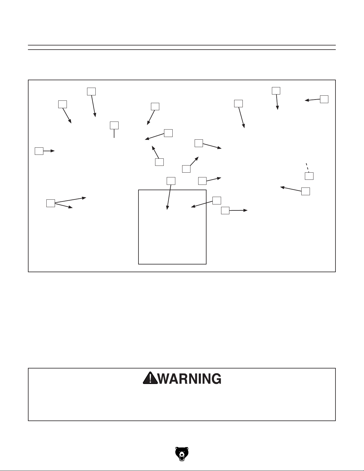
Identification
Become familiar with the names and locations of the controls and features shown below to better understand
the instructions in this manual.
B
A
C
S
R
D
E
F
Q
O
P
N
M
G
L
H
I
J
K
A. Control Panel
B. Belt Tracking Knob
C. Attachment Arm Lock Handle (1 of 6)
D. Eye Shield
E. Platen
F. Contact Wheel
G. Abrasive Belt
H. Idler Wheel
I. Belt Tension Crank
J. Drive Wheel
K. Master Power Switch
L. EMERGENCY STOP Button
M. Pipe Vise
N. Spark Trap
O. Table
P. Profile Roller
Q. Platen Tool Rest
R. Grinding Attachment Storage Slots
S. Motor
For Your Own Safety Read Instruction Manual Before Operating Sander
a) Wear eye protection.
b) Support workpiece with tool rest.
c) Maintain 1⁄16 in. maximum clearance between tool rest and abrasive belt.
Model G0972 (Mfd. Since 10/23)
-3-
Page 6
Controls &
To reduce your risk of
serious injury, read this
entire manual BEFORE
Power Controls
Components
using machine.
Like all machinery there is potential danger
when operating this machine. Accidents
are frequently caused by lack of familiarity
or failure to pay attention. Use this machine
with respect and caution to decrease the
risk of operator injury. If normal safety precautions are overlooked or ignored, serious personal injury may occur.
No list of safety guidelines can be complete. Every shop environment is different.
Always consider safety first, as it applies
to your individual working conditions. Use
this and other machinery with caution and
respect. Failure to do so could result in
serious personal injury, damage to equipment, or poor work results.
A
Figure 1. Control panel components.
A. Variable-Speed Dial: Rotates to adjust motor
and belt speed.
B. Stop Button: Turns motor OFF and disables
machine when pressed. Twist clockwise to
reset.
C. ON/OFF Buttons: ON button (I) turns motor
ON and illuminates power indicator on switch.
OFF button (O) turns motor OFF.
B
C
E
Refer to the following figures and descriptions to
become familiar with the basic controls and components of this machine. Understanding these
items and how they work will help you understand
the rest of the manual and minimize your risk of
injury when operating this machine.
Note: The lock handles on this machine are
adjustable. If the movement of a lock handle is
obstructed, pull the handle away from the handle
shaft to reposition it as needed.
-4-
D
Figure 2. Other power controls.
D. EMERGENCY STOP Button: Turns machine
OFF and disables power when pressed.
Twist clockwise to reset.
E. Master Power Switch: Turns incoming
power ON (I) and OFF (0).
Model G0972 (Mfd. Since 10/23)
Page 7
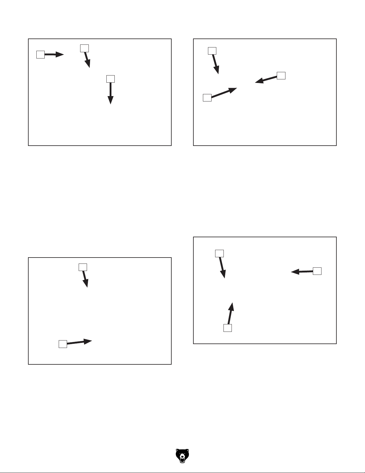
Main Grinding Components
Platen Grinding Attachment
G
F
H
Figure 3. Belt adjustment components.
F. Belt Tension Crank: Increases/decreases
belt tension for belt removal or adjustment.
G. Belt Tracking Knob: Fine-tunes belt track-
ing along wheels and installed grinding
attachment.
H. Attachment Arm Lock Handle (1 of 6):
Secures position of attachment arms. Lock
handles used will depend on grinding attachments installed.
K
L
M
Figure 5. Platen grinding attachment.
K. Platen Tool Rest: Supports workpiece for
grinding operations against platen.
L. Platen Tilt Lock Handle: Loosen to adjust
platen angle and tighten to secure.
M. Platen: Provides flat surface belt support.
Contact Wheel Grinding Attachment
N
I
J
Figure 4. Eye shield and spark trap.
I. Eye Shield: Protects against sparks during
operations. This shield is not a substitute for
personal protective equipment.
J. Spark Trap: Collects sparks and grinding
dust during operations.
O
P
Figure 6. Contact wheel grinding attachment.
N. Table: Supports workpiece for grinding oper-
ations against contact wheel.
O. Contact Wheel: Provides curved surface
belt support.
P. Table Tilt Lock Handle: Loosen to adjust
table angle and tighten to secure.
Model G0972 (Mfd. Since 10/23)
-5-
Page 8
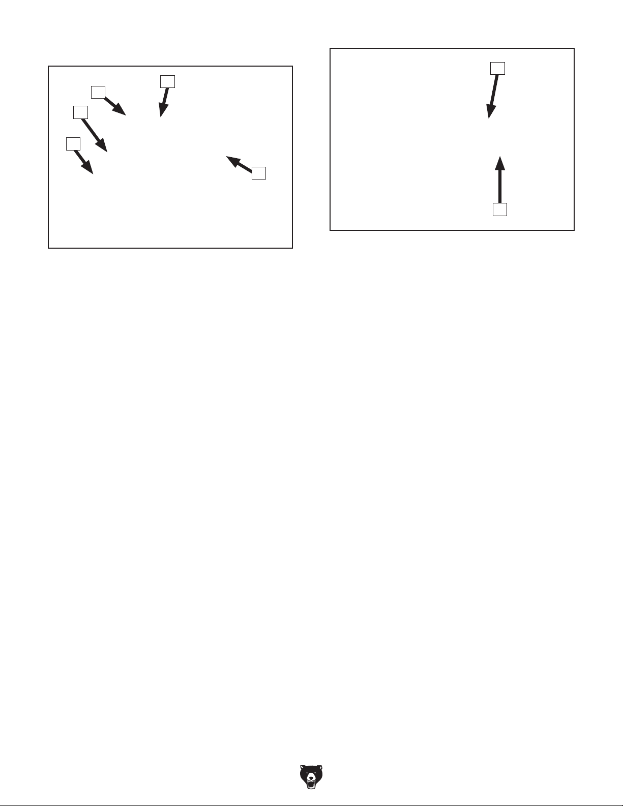
Pipe Grinding Attachments
T
S
R
Q
V
U
W
Figure 8. Pipe feeding components.
Figure 7. Pipe holding components.
Q. Cross Slide Bracket: Allows left and right
vise adjustments in relation to profile roller to
align workpiece with roller.
R. Vise Angle Lock Handle: Loosen to adjust
vise angle and tighten to secure.
S. Fixed Vise Jaw: Helps hold workpiece dur-
ing notching operations.
T. Adjustable Vise Jaw: Secures workpiece
against fixed vise jaw during notching
operations.
U. Vise Leadscrew Handle: Adjusts adjustable
vise jaw in relation to fixed vise jaw.
V. Profile Roller: Provides curved surface belt
support for workpiece notching operations.
W. Vise Slide Shaft (1 of 2): Allows operator to
move vise toward or away from profile roller
to feed workpiece into abrasive belt.
-6-
Model G0972 (Mfd. Since 10/23)
Page 9

Machine Data Sheet
MACHINE DATA
SHEET
Customer Service #: (570) 546-9663 · To Order Call: (800) 523-4777 · Fax #: (800) 438-5901
MODEL G0972 3" X 78" KNIFE-MAKING GRINDER
MODEL G0972 3" X 78" KNIFE MAKING GRINDER
Product Dimensions:
Weight.............................................................................................................................................................. 276 lbs.
Width (side-to-side) x Depth (front-to-back) x Height..................................................................... 32-1/2 x 45 x 49 in.
Footprint (Length x Width)............................................................................................................................ 22 x 22 in.
Shipping Dimensions:
Type......................................................................................................................................................... Wooden Box
Content........................................................................................................................................................... Machine
Weight.............................................................................................................................................................. 353 lbs.
Length x Width x Height....................................................................................................................... 32 x 30 x 41 in.
Must Ship Upright................................................................................................................................................... Yes
Electrical:
Power Requirement........................................................................................................... 220V, Single-Phase, 60 Hz
Full-Load Current Rating........................................................................................................................................ 11A
Minimum Circuit Size.............................................................................................................................................. 15A
Connection Type....................................................................................................................................... Cord & Plug
Power Cord Included.............................................................................................................................................. Yes
Power Cord Length.............................................................................................................................................. 98 in.
Power Cord Gauge......................................................................................................................................... 14 AWG
Plug Included.......................................................................................................................................................... Yes
Included Plug Type................................................................................................................................................ 6-15
Switch Type............................................................................................ Control Panel w/Magnetic Switch Protection
Inverter (VFD) Type......................................................................................................................... Delta VFD-MS300
Inverter (VFD) Size............................................................................................................................................... 3 HP
Motors:
Main
Horsepower................................................................................................................................................ 3 HP
Phase.................................................................................................................................................... 3-Phase
Amps.............................................................................................................................................................. 9A
Speed....................................................................................................................................... 526 - 2350 RPM
Type........................................................................................................................................... TEFC Induction
Power Transfer ......................................................................................................................................... Direct
Bearings..................................................................................................... Shielded & Permanently Lubricated
Model G0972 (Mfd. Since 10/23)
-7-
Page 10

Main Specifications:
Belt Sander Info
Sanding Belt Width...................................................................................................................................... 3 in.
Sanding Belt Length............................................................................................................................ 78-3/4 in.
Sanding Belt Speed................................................................................................................ 1021 - 5768 FPM
Sanding Belt Tilt................................................................................................................................. 0, 90 deg.
Table Length........................................................................................................................................ 8-1/16 in.
Table Width.................................................................................................................................................. 6 in.
Table Thickness........................................................................................................................................ 1/8 in.
Table Tilt............................................................................................................................................ 0 - 45 deg.
Contact Wheel Diameter....................................................................................................................... 7-7/8 in.
Contact Wheel Width................................................................................................................................... 3 in.
Drive Wheel Diameter........................................................................................................................... 7-7/8 in.
Drive Wheel Width....................................................................................................................................... 3 in.
Belt Tension Release Type................................................................................................ Spring & Leadscrew
Platen Type.............................................................................................................................. Graphite-Coated
Platen Length........................................................................................................................................ 5-1/4 in.
Platen Width................................................................................................................................................ 4 in.
Idler Wheel Diameter............................................................................................................................. 2-7/8 in.
Idler Wheel Width........................................................................................................................................ 3 in.
Construction Materials
Stand.......................................................................................................................................................... Steel
Table.................................................................................................................................................... Cast Iron
Frame......................................................................................................................................................... Steel
Paint Type/Finish....................................................................................................................... Powder Coated
Other Specifications:
Country of Origin ................................................................................................................................................ China
Warranty ........................................................................................................................................................... 1 Year
Approximate Assembly & Setup Time ........................................................................................................ 45 Minutes
Serial Number Location ................................................................................................................... Machine ID Label
Sound Rating ..................................................................................................................................................... 85 dB
ISO 9001 Factory .................................................................................................................................................. Yes
Features:
Frame Pivots 90 Deg. for Vertical or Horizontal Grinding
Platen Tilts 0 - 45 Deg.
Variable-Speed Motor and Belt Speed
Aluminum Drive and Idler Wheels
Dual Emergency Stop Buttons
Grinding Attachment & Profile Roller Storage Slots in Stand
Accessories Included:
3" x 78-3/4" 80-Grit Zirconia Alumina Y-Weight Belt
7-7/8" Dia. Contact Wheel Grinding Attachment GraphiteCoated Platen Grinding Attachment w/Tool Rest
8-1/16" x 6" Table
Magnet-Mounted Spark Trap
Pipe Vise w/Cross Slide and Angle Adjustment
Profile Roller Notching Attachment
0.964" Profile Roller
-8-
Model G0972 (Mfd. Since 10/23)
Page 11
SECTION 1: SAFETY
For Your Own Safety, Read Instruction
Manual Before Operating This Machine
The purpose of safety symbols is to attract your attention to possible hazardous conditions.
This manual uses a series of symbols and signal words intended to convey the level of importance of the safety messages. The progression of symbols is described below. Remember that
safety messages by themselves do not eliminate danger and are not a substitute for proper
accident prevention measures. Always use common sense and good judgment.
Indicates an imminently hazardous situation which, if not avoided,
WILL result in death or serious injury.
Indicates a potentially hazardous situation which, if not avoided,
COULD result in death or serious injury.
Indicates a potentially hazardous situation which, if not avoided,
MAY result in minor or moderate injury. It may also be used to alert
against unsafe practices.
Alerts the user to useful information about proper operation of the
NOTICE
machine to avoid machine damage.
Safety Instructions for Machinery
OWNER’S MANUAL. Read and understand this
owner’smanualBEFOREusingmachine.
TRAINED OPERATORS ONLY. Untrained operators have a higher risk of being hurt or killed.
Only allow trained/supervised people to use this
machine. When machine is not being used, disconnect power, remove switch keys, or lock-out
machine to prevent unauthorized use—especially
around children. Make your workshop kid proof!
DANGEROUS ENVIRONMENTS. Do not use
machinery in areas that are wet, cluttered, or have
poor lighting. Operating machinery in these areas
greatly increases the risk of accidents and injury.
MENTAL ALERTNESS REQUIRED. Full mental
alertness is required for safe operation of machinery. Never operate under the influence of drugs or
alcohol, when tired, or when distracted.
ELECTRICAL EQUIPMENT INJURY RISKS.
You can be shocked, burned, or killed by touching
live electrical components or improperly grounded
machinery. To reduce this risk, only allow qualified
service personnel to do electrical installation or
repair work, and always disconnect power before
accessing or exposing electrical equipment.
DISCONNECT POWER FIRST.
nect machine from power supply BEFORE making adjustments, changing tooling, or servicing
machine. This prevents an injury risk from unintended startup or contact with live electrical components.
EYE PROTECTION. Always wear ANSI-approved
safety glasses or a face shield when operating
or observing machinery to reduce the risk of eye
injury or blindness from flying particles. Everyday
eyeglasses are NOT approved safety glasses.
Always discon-
Model G0972 (Mfd. Since 10/23)
-9-
Page 12

may damage the wires inside. Do not handle
WEARING PROPER APPAREL. Do not wear
loose clothing, gloves, neckties, or jewelry that
can become entangled in moving parts. Always tie
back or cover long hair. Wear non-slip footwear to
reduce risk of slipping and losing control or accidentally contacting cutting tool or moving parts.
HAZARDOUS DUST. Dust created by machinery
operations may cause cancer, birth defects, or
long-term respiratory damage. Be aware of dust
hazards associated with each workpiece material. Always wear a NIOSH-approved respirator to
reduce your risk.
HEARING PROTECTION. Always wear hearing protection when operating or observing loud
machinery. Extended exposure to this noise without hearing protection can cause permanent
hearing loss.
REMOVE ADJUSTING TOOLS. Tools left on
machinery can become dangerous projectiles
upon startup. Never leave chuck keys, wrenches,
or any other tools on machine. Always verify
removal before starting!
USE CORRECT TOOL FOR THE JOB. Only use
this tool for its intended purpose—do not force
it or an attachment to do a job for which it was
not designed. Never make unapproved modifications—modifying tool or using it differently than
intended may result in malfunction or mechanical
failure that can lead to personal injury or death!
AWKWARD POSITIONS. Keep proper footing
and balance at all times when operating machine.
Do not overreach! Avoid awkward hand positions
that make workpiece control difficult or increase
the risk of accidental injury.
CHILDREN & BYSTANDERS. Keep children and
bystanders at a safe distance from the work area.
Stop using machine if they become a distraction.
GUARDS & COVERS. Guards and covers reduce
accidental contact with moving parts or flying
debris. Make sure they are properly installed,
undamaged, and working correctly BEFORE
operating machine.
FORCING MACHINERY. Do not force machine.
It will do the job safer and better at the rate for
which it was designed.
NEVER STAND ON MACHINE. Serious injury
may occur if machine is tipped or if the cutting
tool is unintentionally contacted.
STABLE MACHINE. Unexpected movement during operation greatly increases risk of injury or
loss of control. Before starting, verify machine is
stable and mobile base (if used) is locked.
USE RECOMMENDED ACCESSORIES. Consult
thisowner’smanualorthemanufacturerforrec-
ommended accessories. Using improper accessories will increase the risk of serious injury.
UNATTENDED OPERATION. To reduce the
risk of accidental injury, turn machine OFF and
ensure all moving parts completely stop before
walking away. Never leave machine running
while unattended.
MAINTAIN WITH CARE. Follow all maintenance
instructions and lubrication schedules to keep
machine in good working condition. A machine
that is improperly maintained could malfunction,
leading to serious personal injury or death.
DAMAGED PARTS. Regularly inspect machine
for damaged, loose, or mis-adjusted parts—or
any condition that could affect safe operation.
Immediately repair/replace BEFORE operating
machine. For your own safety, DO NOT operate
machine with damaged parts!
MAINTAIN POWER CORDS. When disconnecting cord-connected machines from power, grab
and pull the plug—NOT the cord. Pulling the cord
cord/plug with wet hands. Avoid cord damage by
keeping it away from heated surfaces, high traffic
areas, harsh chemicals, and wet/damp locations.
EXPERIENCING DIFFICULTIES. If at any time
you experience difficulties performing the intended operation, stop using the machine! Contact our
Technical Support at (570) 546-9663.
-10-
Model G0972 (Mfd. Since 10/23)
Page 13

Additional Safety for Metal Belt Grinders
Serious injury or death can occur from fingers, clothing, jewelry, or hair getting pinched/entangled
in rotating belt or other moving components. Abrasion injuries can occur from touching moving
abrasive belt with bare skin. Workpieces or ground-off particles thrown by abrasive belt can
strike operator or bystanders, causing impact injuries, burns, or blindness. Flying sparks can
ignite nearby explosive or flammable materials. Long-term respiratory damage can occur from
using grinder without wearing a respirator. To reduce the risk of these hazards, operator and
bystanders MUST completely heed the hazards and warnings below.
USE FOR INTENDED PURPOSE. This machine
is designed for grinding carbon steel, tool steel,
and stainless steel. DO NOT use it to grind nonmetal materials.
DUST, SPARKS, & HOT MATERIALS. Grinding
creates large amounts of airborne dust particles
and sparks that can cause eye injury, respiratory illness, or burns. Grinding friction will cause
workpiece to quickly get hot, causing burns to skin.
Reduce your risk by always wearing approved
eye, respiratory, and skin protection when using
grinder. Use spark trap and adjust eye shields to
best protect against sparks. Never allow anyone
to stand in path of sparks. Do not touch freshly
ground surfaces or nearby areas without first cooling them or allowing them to cool.
TOXIC MATERIALS. Exposure to certain dusts
or fumes, like those from lead, asbestos, crystalline silica, tantalum, hafnium, niobium, titanium,
etc., can result in potentially deadly health effects.
Research toxic effects of materials you work with,
and always seek to minimize/eliminate exposure to
yourself and others.
WORKPIECE INTEGRITY & SUPPORT. Grinding
fragile workpieces can result in loss of control,
resulting in abrasion injuries, pinch/impact injuries, or damage to abrasive belt. Only grind solid
workpieces that can withstand power grinding
forces. Avoid grinding workpieces without flat bottom surfaces unless some type of jig is used to
maintain support and control when grinding force
is applied. Always use a jig or other holding device
when grinding small workpieces, and keep hands
and fingers at least 2" away from abrasive surface.
Always grind with workpiece firmly against rest or
another support device, if feasible.
FLAMMABLE MATERIALS. Grinding causes
sparks that can ignite flammable or combustible
materials near machine. Fine metal dust particles
can ignite, depending on material type and circumstances. Aluminum, titanium, niobium, tantalum,
zirconium, hafnium, etc. produce flammable dust.
Learn fire hazards of materials you are using and
be prepared to effectively fight a combustible
metal fire. Do not use grinding belt for multiple
material types and clean spark trap between mate
rials. Never use this machine to grind magnesium.
-
IN-RUNNING NIP POINTS. Gap between moving
belt and tool rest/table creates pinch point for fingers or workpieces; the larger the gap, the greater
risk of fingers or workpieces getting caught in it.
Minimize risk of pinch and crush injuries by adjusting tool rest/table to within
ABRASIVE BELT. Worn or damaged abrasive
belts can fly apart and throw debris, or aggressively grab workpiece, causing injury from operator loss of workpiece control. Always inspect
belt before operation and replace if worn or
damaged. Rotating belt can remove skin quickly.
Always keep hands away from moving belt during
operation.
Model G0972 (Mfd. Since 10/23)
1
⁄16 " of belt.
FEEDING WORKPIECE. Forcefully jamming
workpiece into abrasive surface could cause it to
be grabbed aggressively, pulling hands into abrasive surface. Avoid introducing sharp edges into
moving belt on leading side of workpiece. Properly
support workpiece and only grind against direction
of abrasive belt travel. Firmly grasp workpiece or
holding jig in both hands and ease workpiece into
belt using light pressure.
AVOIDING ENTANGLEMENT. Becoming
entangled in moving parts can cause severe injury
or death. Keep all guards in place and closed; DO
NOT wear loose clothing, gloves, or jewelry; and
tie back long hair.
-11-
Page 14
SECTION 2: POWER SUPPLY
Before installing the machine, consider the availability and proximity of the required power supply
circuit. If an existing circuit does not meet the
requirements for this machine, a new circuit must
be installed. To minimize the risk of electrocution,
fire, or equipment damage, installation work and
electrical wiring must be done by an electrician or
qualified service personnel in accordance with all
applicable codes and standards.
or equipment damage
may occur if machine is
not properly grounded
and connected to power
The full-load current rating is the amperage a
machine draws at 100% of the rated output power.
On machines with multiple motors, this is the
amperage drawn by the largest motor or sum of all
motors and electrical devices that might operate
at one time during normal operations.
The full-load current is not the maximum amount
of amps that the machine will draw. If the machine
is overloaded, it will draw additional amps beyond
the full-load rating.
If the machine is overloaded for a sufficient length
of time, damage, overheating, or fire may result—
especially if connected to an undersized circuit.
To reduce the risk of these hazards, avoid overloading the machine during operation and make
sure it is connected to a power supply circuit that
meets the specified circuit requirements.
For your own safety and protection of
Note: Circuit requirements in this manual apply to
a dedicated circuit—where only one machine will
be running on the circuit at a time. If machine will
be connected to a shared circuit where multiple
machines may be running at the same time, consult an electrician or qualified service personnel to
ensure circuit is properly sized for safe operation.
A power supply circuit includes all electrical
equipment between the breaker box or fuse panel
in the building and the machine. The power supply circuit used for this machine must be sized to
safely handle the full-load current drawn from the
machine for an extended period of time. (If this
machine is connected to a circuit protected by
fuses, use a time delay fuse marked D.)
This machine is prewired to operate on a power
supply circuit that has a verified ground and meets
the following requirements:
Availability
Electrocution, fire, shock,
supply.
Full-Load Current Rating
Circuit Information
property, consult an electrician if you are
unsure about wiring practices or electrical
codes in your area.
Full-Load Current Rating at 220V ..... 11 Amps
-12-
Circuit Requirements
Nominal Voltage .........208V, 22 0V, 23 0V, 24 0V
..........................................................60 Hz
Cycle
Phase
Power Supply Circuit
Plug/Receptacle
........................................... Single-Phase
......................... 15 Amps
............................. NEMA 6-15
Model G0972 (Mfd. Since 10/23)
Page 15
Improper connection of the equipment-grounding
wire can result in a risk of electric shock. The
wire with green insulation (with or without yellow
stripes) is the equipment-grounding wire. If repair
or replacement of the power cord or plug is necessary, do not connect the equipment-grounding
wire to a live (current carrying) terminal.
Check with a qualified electrician or service personnel if you do not understand these grounding
requirements, or if you are in doubt about whether
the tool is properly grounded. If you ever notice
that a cord or plug is damaged or worn, disconnect it from power, and immediately replace it with
We do not recommend using an extension cord
with this machine. If you must use an extension
cord, only use it if absolutely necessary and only
on a temporary basis.
Extension cords cause voltage drop, which can
damage electrical components and shorten motor
life. Voltage drop increases as the extension cord
size gets longer and the gauge size gets smaller
(higher gauge numbers indicate smaller sizes).
Any extension cord used with this machine must
be in good condition and contain a ground wire
and matching plug/receptacle. Additionally, it must
meet the following size requirements:
Grounding Requirements
This machine MUST be grounded. In the event
of certain malfunctions or breakdowns, grounding
reduces the risk of electric shock by providing a
path of least resistance for electric current.
This machine is equipped with a power cord that
has an equipment-grounding wire and a grounding
plug. Only insert plug into a matching receptacle
(outlet) that is properly installed and grounded in
accordance with all local codes and ordinances.
DO NOT modify the provided plug!
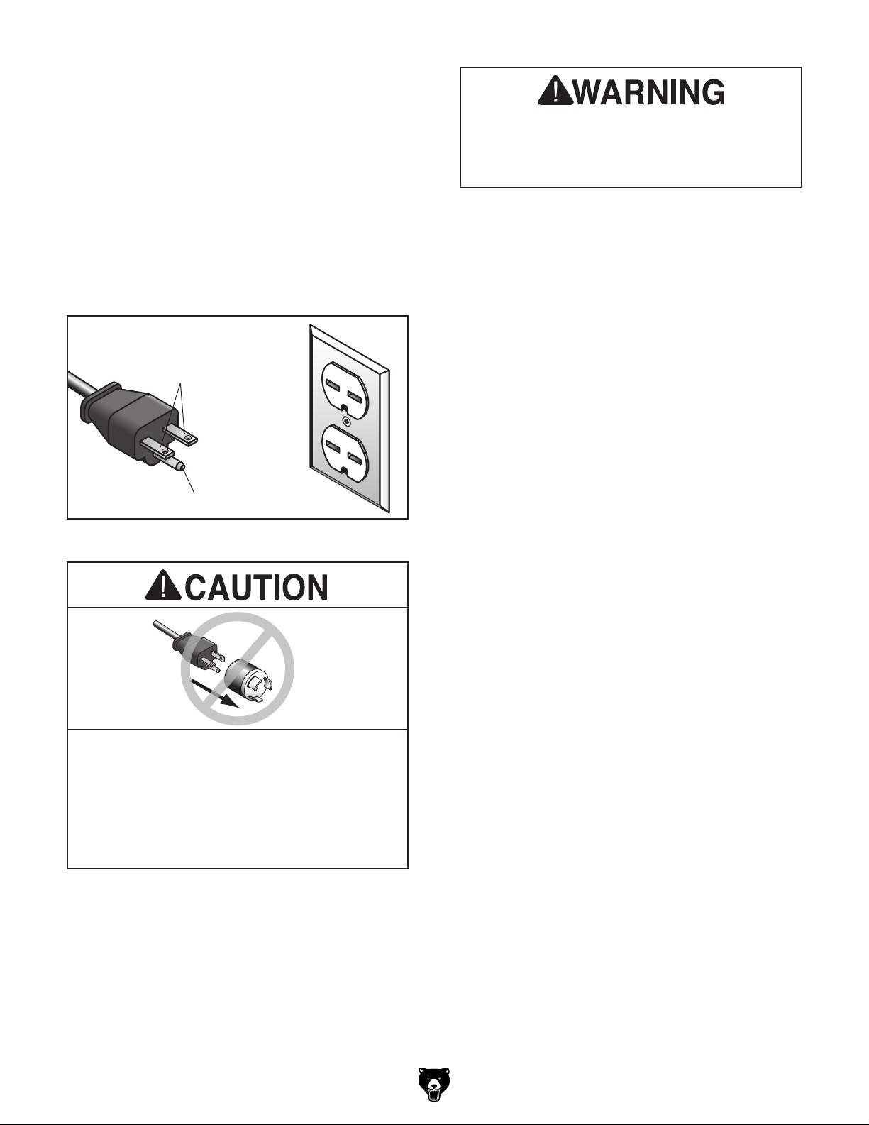
No adapter should be used with plug. If
GROUNDED
6-15 RECEPTACLE
Current Carrying Prongs
6-15 PLUG
Serious injury could occur if you connect
machine to power before completing setup
process. DO NOT connect to power until
instructed later in this manual.
Grounding Pin
Figure 9. Typical 6-15 plug and receptacle.
plug does not fit available receptacle, or if
machine must be reconnected for use on a
different type of circuit, reconnection must
be performed by an electrician or qualified
service personnel, and it must comply with
all local codes and ordinances.
Model G0972 (Mfd. Since 10/23)
Extension Cords
Minimum Gauge Size ........................... 16 AWG
Maximum Length (Shorter is Better)
.......50 ft.
-13-
Page 16
SECTION 3: SETUP
The following items are needed, but not included,
for the setup/assembly of this machine.
This machine was carefully packaged for safe
transport. When unpacking, separate all enclosed
items from packaging materials and inspect them
for shipping damage.
,
please
IMPORTANT: Save all packaging materials until
you are completely satisfied with the machine and
have resolved any issues between Grizzly or the
shipping agent. You MUST have the original pack-
aging to file a freight claim. It is also extremely
helpful if you need to return your machine later.
Needed for Setup
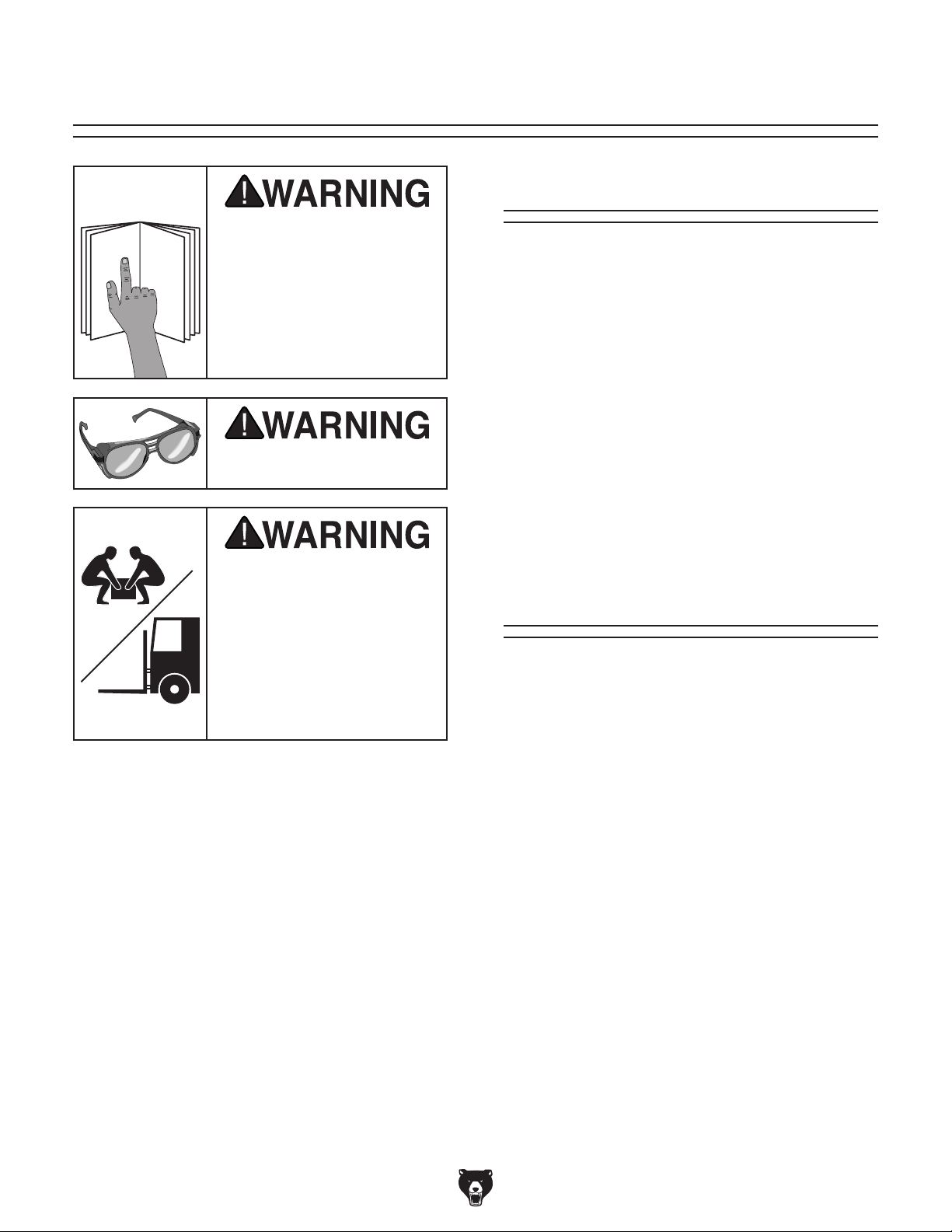
This machine presents
serious injury hazards
to untrained users. Read
through this entire manual to become familiar with
the controls and operations before starting the
machine!
Wear safety glasses during
the entire setup process!
Description Qty
• Disposable Rags ........................ As Needed
• Cleaner/Degreaser ..................... As Needed
• Safety Glasses (for each person) .......... 1 Pr.
• Disposable Gloves ..................... As Needed
• Lifting Straps (Rated for at least 450 lbs.) .. 2
• Lifting Equipment
(Rated for at least 450 lbs.) ........................ 1
• Hex Wrench 6mm ....................................... 1
• Wrench or Socket 10mm ............................ 1
• Open-End Wrench 5⁄8" ................................ 1
• Mounting Hardware .................... As Needed
HEAVY LIF T!
Straining or crushing injury
may occur from improperly
lifting machine or some of
its parts. To reduce this risk,
get help from other people
and use a forklift (or other
lifting equipment) rated for
weight of this machine.
Unpacking
If items are damaged
call us immediately at (570) 546-9663.
-14-
Model G0972 (Mfd. Since 10/23)
Page 17
Inventory
The following is a list of items shipped with your
machine. Before beginning setup, lay these items
out and inventory them.
If any non-proprietary parts are missing (e.g. a
nut or a washer), we will gladly replace them; or
for the sake of expediency, replacements can be
obtained at your local hardware store.
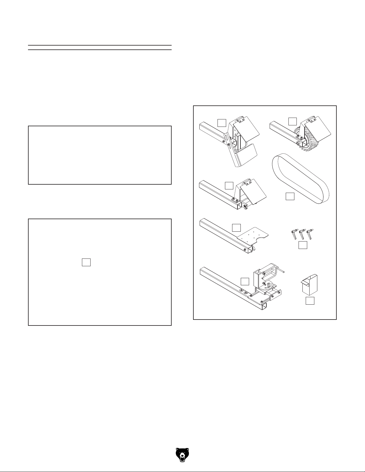
Loose Items (Figure 11) Qty
B. Platen Grinding Attachment ....................... 1
C. Contact Wheel Grinding Attachment .......... 1
D. Profile Roller Notching Attachment ............ 1
E. Abrasive Belt 3" x 783⁄4" 80-Grit ................. 1
F. Table Arm ................................................... 1
G. Lock Handles.............................................. 3
H. Pipe Vise Attachment ................................. 1
I. Spark Trap .................................................. 1
NOTICE
If you cannot find an item on this list, carefully check around/inside the machine and
packaging materials. Often, these items get
lost in packaging materials while unpacking or they are pre-installed at the factory.
Machine (Figure 10) Qty
A. Grinder ....................................................... 1
A
B
D
F
H
C
E
G
Figure 10. Machine inventory.
Model G0972 (Mfd. Since 10/23)
I
Figure 11. Loose item inventory.
-15-
Page 18
Cleanup
parts of the
The unpainted surfaces of your machine are
coated with a heavy-duty rust preventative that
prevents corrosion during shipment and storage.
This rust preventative works extremely well, but it
will take a little time to clean.
Be patient and do a thorough job cleaning your
machine. The time you spend doing this now will
give you a better appreciation for the proper care
of your machine's unpainted surfaces.
There are many ways to remove this rust preventative, but the following steps work well in a wide
variety of situations. Always follow the manufac-
turer’sinstructions withanycleaningproductyou
use and make sure you work in a well-ventilated
area to minimize exposure to toxic fumes.
Before cleaning, gather the following:
• Disposable rags
• Cleaner/degreaser (WD•40 works well)
• Safety glasses & disposable gloves
• Plastic paint scraper (optional)
Basic steps for removing rust preventative:
1.
2.
3.
4.
Many cleaning solvents
work in a well-ventilated
Cleanup
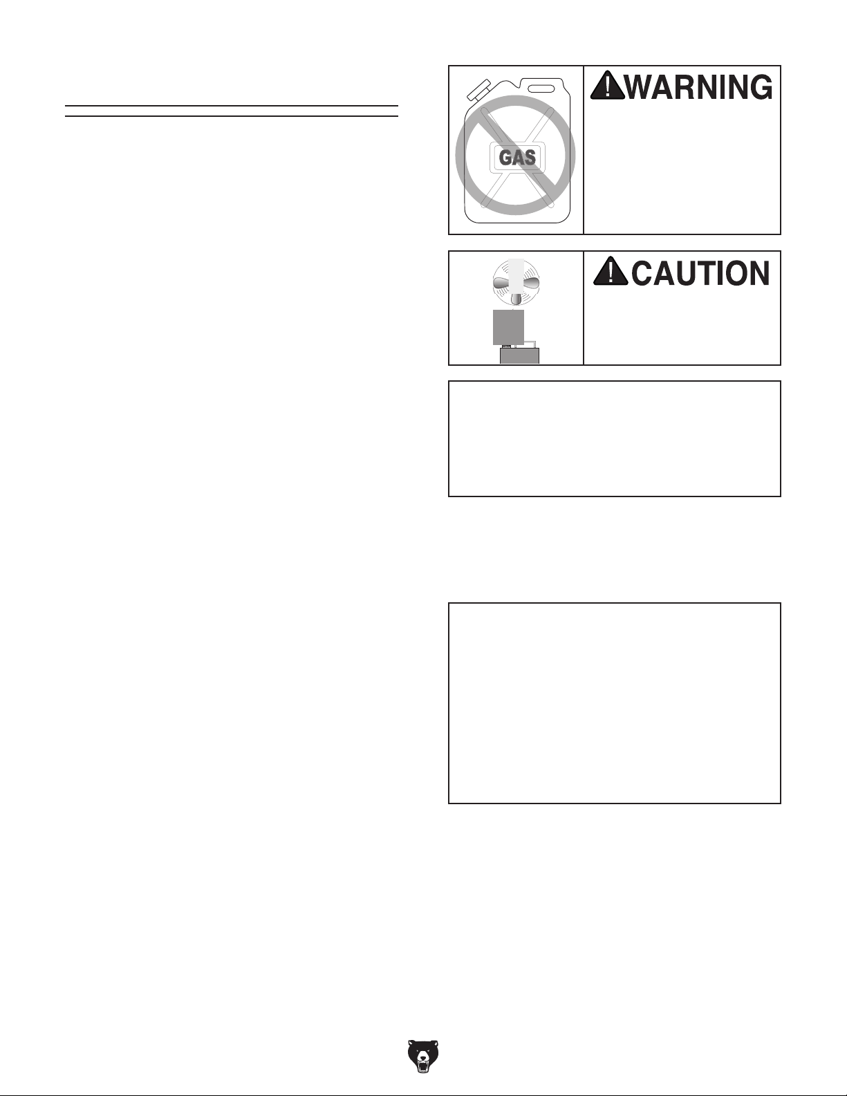
Gasoline and petroleum
products have low flash
points and can explode
or cause fire if used to
clean machinery. Avo i d
using these products
to clean machinery.
Put on safety glasses.
Coat the rust preventative with a liberal
amount of cleaner/degreaser, then let it soak
for 5–10 minutes.
Wipe off the surfaces. If your cleaner/degreas-
er is effective, the rust preventative will wipe
off easily. If you have a plastic paint scraper,
scrape off as much as you can first, then wipe
off the rest with the rag.
are toxic if inhaled. Only
area.
NOTICE
Avoid harsh solvents like acetone or brake
parts cleaner that may damage painted surfaces. Always test on a small, inconspicuous location first.
T23692—Orange Power Degreaser
A great product for removing the waxy shipping grease from the non-painted
machine during clean up.
Order online at
www.grizzly.com
OR
Call 1-800-523-4777
Repeat Steps 2–3 as necessary until clean,
then coat all unpainted surfaces with a quality
metal protectant to prevent rust.
-16-
Figure 12. T23692 Orange Power Degreaser.
Model G0972 (Mfd. Since 10/23)
Page 19
Site Considerations
Weight Load
Refer to the
of your machine. Make sure that the surface upon
which the machine is placed will bear the weight
of the machine, additional equipment that may be
installed on the machine, and the heaviest workpiece that will be used. Additionally, consider the
weight of the operator and any dynamic loading
that may occur when operating the machine.
Space Allocation
Consider the largest size of workpiece that will
be processed through this machine and provide
enough space around the machine for adequate
operator material handling or the installation of
auxiliary equipment. With permanent installations,
leave enough space around the machine to open
or remove doors/covers as required by the maintenance and service described in this manual.
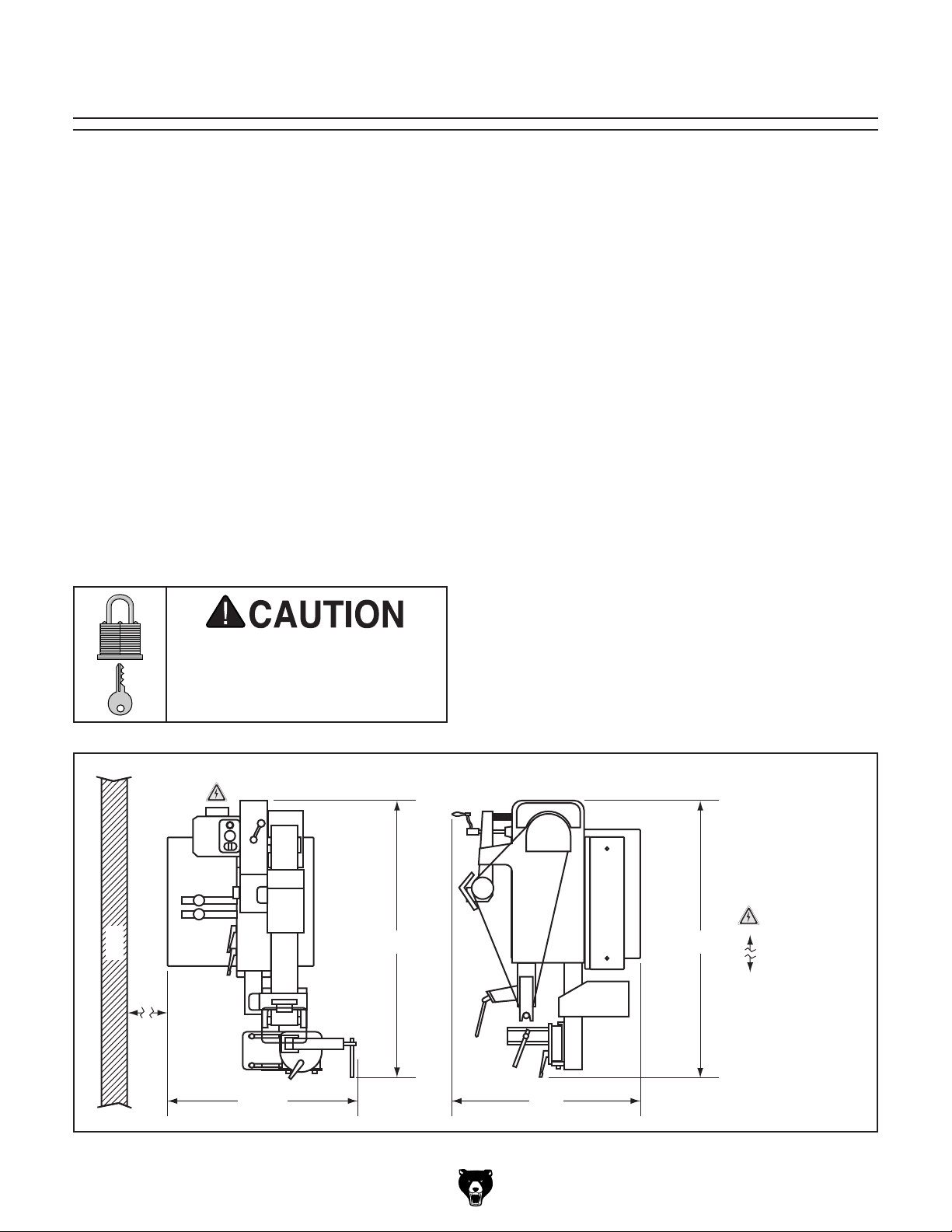
See below for required space allocation.
Physical Environment
The physical environment where the machine is
operated is important for safe operation and longevity of machine components. For best results,
operate this machine in a dry environment that is
free from excessive moisture, hazardous chemicals, airborne abrasives, or extreme conditions.
Extreme conditions for this type of machinery are
generally those where the ambient temperature
range exceeds 41°–104°F; the relative humidity
range exceeds 20%–95% (non-condensing); or
the environment is subject to vibration, shocks,
Place this machine near an existing power source.
Make sure all power cords are protected from
traffic, material handling, moisture, chemicals, or
other hazards. Make sure to leave enough space
around machine to disconnect power supply or
Lighting around the machine must be adequate
enough that operations can be performed safely.
Shadows, glare, or strobe effects that may distract
or impede the operator must be eliminated.
Machine Data Sheet for the weight
or bumps.
Electrical Installation
Children or untrained people
may be seriously injured by
this machine. Only install in an
access restricted location.
Frame Vertical
Wall
apply a lockout/tagout device, if required.
Lighting
45"
Frame Horizontal
45"
Electrical
=
Connection
= Min. 30"
32½"
Model G0972 (Mfd. Since 10/23)
30"
Figure 13. Minimum working clearances.
-17-
Page 20
Assembly
The machine must be fully assembled before it
can be operated. Before beginning the assembly
process, refer to
and gather
all
To ensure the assembly process
goes smoothly, first clean any
ered or coated in heavy-duty rust preventative (if
applicable).
listed items.
Needed for Setup
parts that are cov-
2.
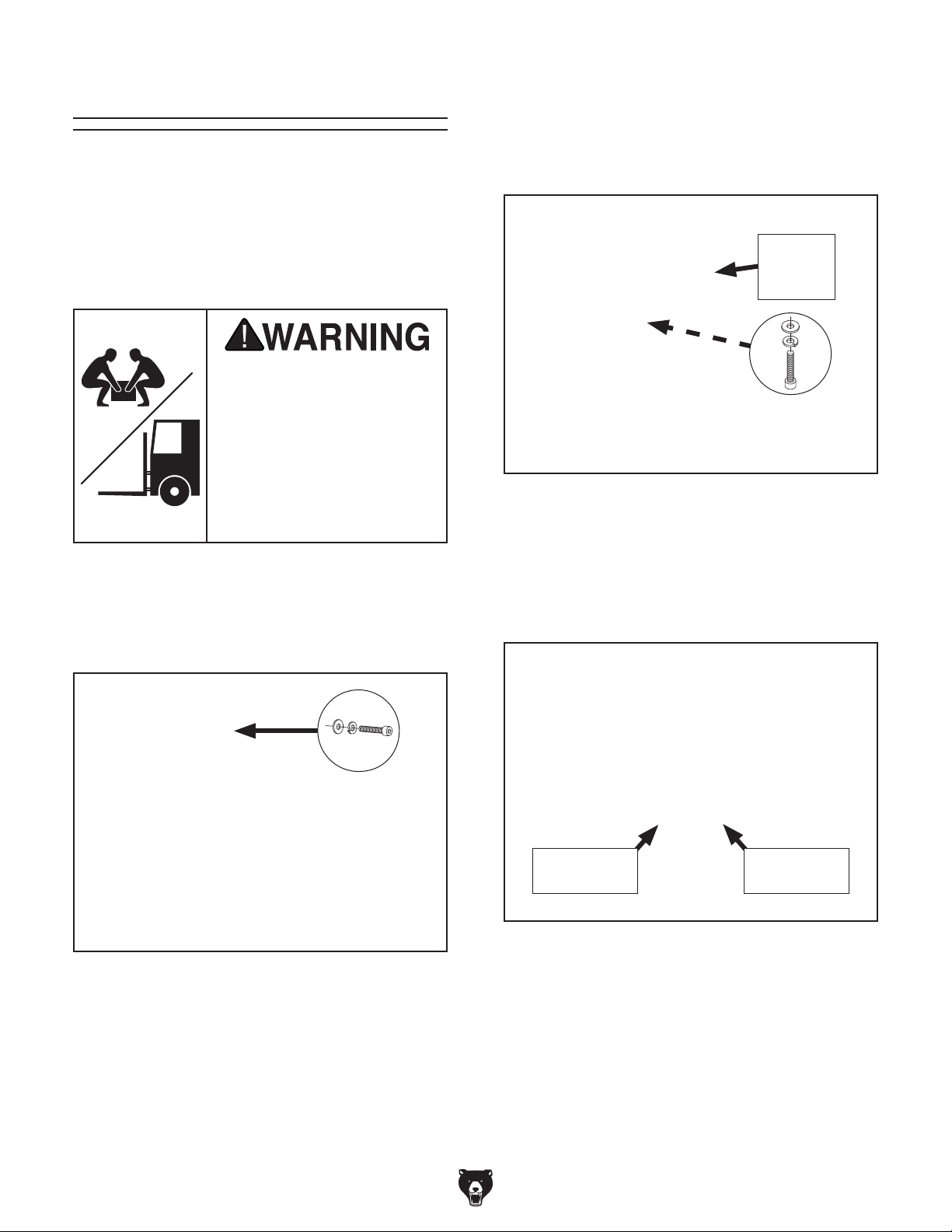
Tilt upper machine frame to vertical position,
as shown in Figure 15.
Re-install fasteners removed in Step 1 to
3.
secure upper machine frame (see Figure 15).
Upper
Machine
Frame
HEAVY LIF T!
Straining or crushing injury
may occur from improperly
lifting machine or some of
its parts. To reduce this risk,
get help from other people
and use a forklift (or other
lifting equipment) rated for
weight of this machine.
To assemble machine:
Remove (2) cap screws, lock washers, and
1.
flat washers shown in Figure 14.
x 2
x 2
Figure 15. Upper machine frame in vertical
position.
4.
Place (2) lifting straps under upper machine
frame, as shown in Figure 16, and attach
straps securely to forklift or other power lifting
equipment.
Figure 14. Machine as shipped.
-18-
Lifting Strap
Location
Figure 16. Lifting strap locations.
Model G0972 (Mfd. Since 10/23)
Lifting Strap
Location
Page 21
Remove bolts securing machine to pallet,
5.
then use lifting equipment to lift machine just
enough to remove pallet.
Lower machine and remove lifting straps.
6.
9. Insert contact wheel grinding attachment arm
into upper arm slot (see Figure 19).
Note: Loosen upper arm slot lock handle
(see Figure 19) if it prevents this step.
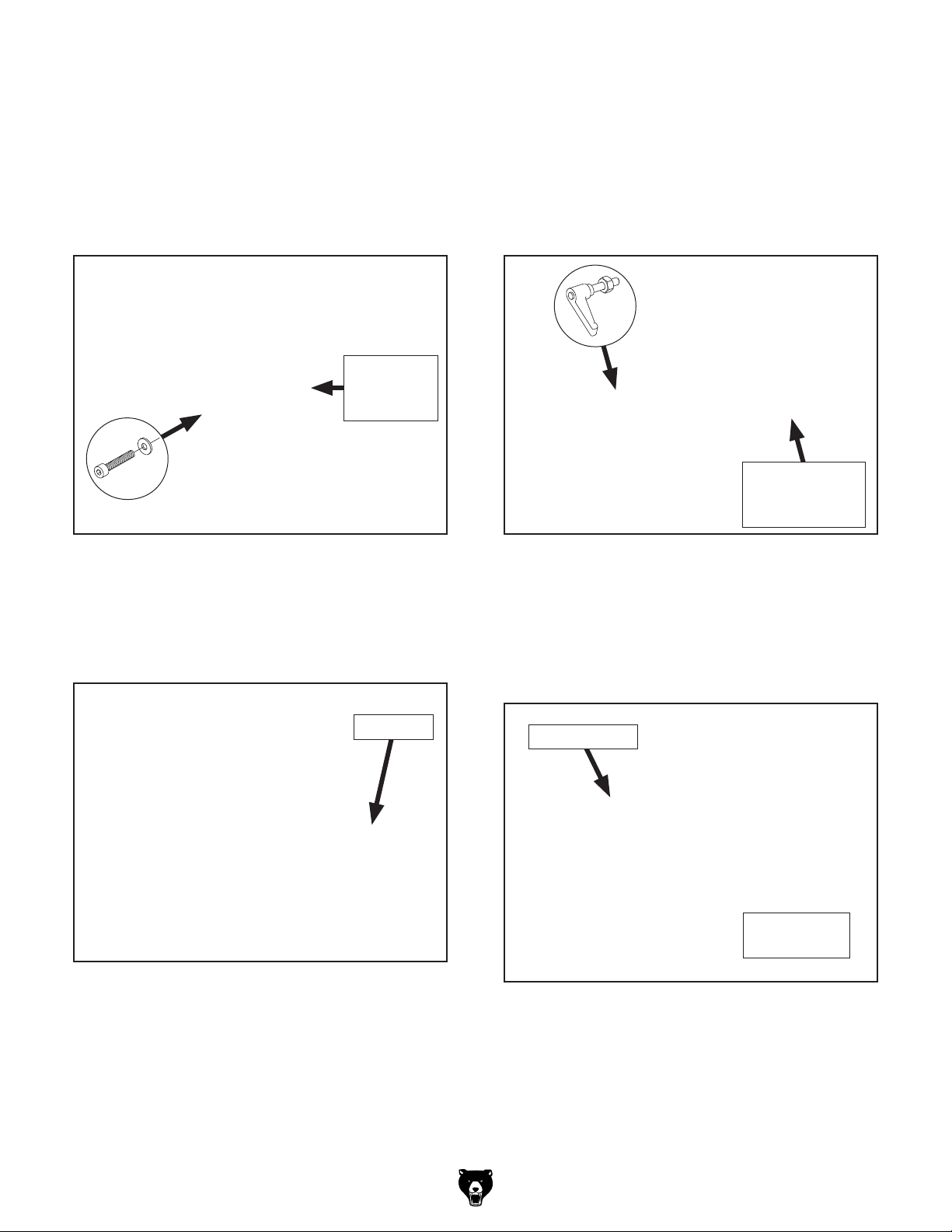
7. Remove cap screw and flat washer shown in
Figure 17 on platen grinding attachment arm.
Platen
Grinding
Attachment
Figure 17. Platen grinding attachment fasteners
to remove.
8.
Position platen tool rest as shown in Figure
18, then re-install fasteners removed in
Step 7.
Install (3) lock handles in upper machine
10.
frame (see Figure 19).
x 3
Contact Wheel
Grinding
Attachment
Figure 19. Contact wheel grinding attachment
and lock handles installed.
11. Install abrasive belt around wheels, center-
ing belt on wheels and being sure arrows on
belt match rotation arrow on machine (see
Figure 20).
Tool Rest
Figure 18. Platen tool rest positioned for
operation.
Abrasive Belt
Belt Rotation
Arrow
Figure 20. Abrasive belt installed around wheels.
Model G0972 (Mfd. Since 10/23)
-19-
Page 22
Anchoring machinery to the floor prevents tipping
or shifting and reduces vibration that may occur
during operation, resulting in a machine that runs
slightly quieter and feels more solid.
If the machine will be installed in a commercial or
workplace setting, or if it is permanently connected (hardwired) to the power supply, local codes
may require that it be anchored to the floor.
If not required by any local codes, fastening the
machine to the floor is an optional step. If you
choose not to do this with your machine, we recommend placing it on machine mounts, as these
provide an easy method for leveling and they have
vibration-absorbing pads.
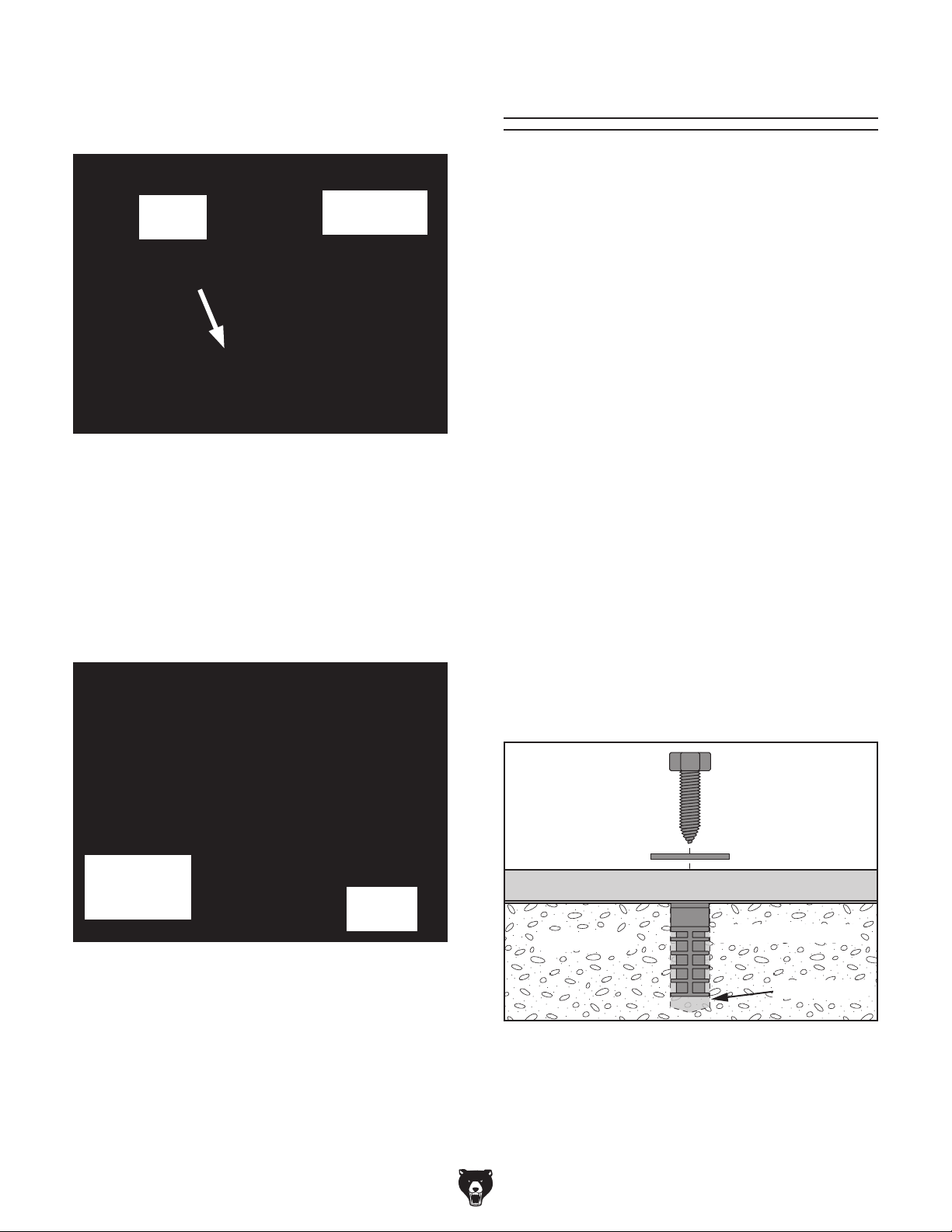
Lag shield anchors with lag screws (see below)
are a popular way to anchor machinery to a concrete floor, because the anchors sit flush with the
floor surface, making it easy to unbolt and move
the machine later, if needed. However, anytime
local codes apply, you MUST follow the anchoring
methodology specified by the code.
12. Adjust belt tension crank (see Figure 21) until
rubber pad on end of crank no longer presses
against machine frame.
Anchoring to Floor
Number of Mounting Holes ............................ 4
Diameter of Mounting Hardware
................7⁄16"
Rubber
Pad
Figure 21. Location of rubber pad on belt
tension crank.
13.
Turn belt tension crank about five turns clock-
wise. This will stretch tension spring so belt
can be installed correctly.
Move contact wheel as far forward as you
14.
can without stretching belt (see Figure 22),
then tighten (2) upper slot lock handles.
Belt Tension
Crank
Anchoring to Concrete Floors
Upper Slot
Lock Handle
(1 of 2)
Figure 22. Contact wheel moved forward.
15. Turn belt tension crank counterclockwise until
rubber pad on end of crank no longer presses
against machine frame. This will release
spring tension and tension belt.
-20-
Contact
Wheel
Lag Screw
Flat Washer
Machine Base
Concrete
Figure 23. Popular method for anchoring
machinery to a concrete floor.
Model G0972 (Mfd. Since 10/23)
Lag Shield Anchor
Drilled Hole
Page 23
Test Run
Once assembly is complete, test run the machine
to ensure it is properly connected to power and
safety components are functioning correctly.
If you find an unusual problem during the test run,
immediately stop the machine, disconnect it from
power, and fix the problem BEFORE operating the
machine again. The
table in the
SERVICE section of this manual can help.
DO NOT start machine until all preceding
setup instructions have been performed.
Operating an improperly set up machine
ed results that can lead to serious injury,
Serious injury or death can result from
Troubleshooting
The Test Run consists of verifying the following: 1)
The belt tracks properly and will not come off the
wheels during initial startup, 2) the motor powers
up and runs correctly, 3) the Stop button works
correctly, and 4) the EMERGENCY STOP button
works correctly.
To test run machine:
Clear all setup tools away from machine.
1.
2. Tie back loose clothing and long hair to pro-
tect yourself from getting caught in moving
belt when you start machine.
Standing in front of machine, push belt mul-
3.
tiple times along contact wheel so it moves in
direction of operation (see Figure 24), then
watch how belt tracks on wheels.
using this machine BEFORE understanding
its controls and related safety information.
DO NOT operate, or allow others to operate,
machine until the information is understood.
may result in malfunction or unexpect-
death, or machine/property damage.
Figure 24. Belt tracking components.
— If belt tracks centered on wheels, proceed
to Step 6.
— If belt does not track centered on wheels,
proceed to Step 4.
Model G0972 (Mfd. Since 10/23)
-21-
Page 24
4. Adjust hex nut on belt tracking knob away
from machine frame (see Figure 25).
8. Press EMERGENCY STOP button in (see
Figure 27).
Use belt tracking knob (see Figure 25) to
5.
adjust belt tracking while continuing to rotate
belt by hand to check adjustment.
— Turn knob clockwise to move belt left on
wheels, and turn knob counterclockwise to
move belt right on wheels.
Belt
Tracking
Knob
Figure 25. Belt tracking components.
6.
Press stop button in (see Figure 26).
Turn variable-speed dial all the way counter-
7.
clockwise (see Figure 26).
Variable-Speed
Dial
Stop
Button
ON Button
Move master power switch to OFF (O) posi-
9.
tion (see Figure 27).
EMERGENCY
STOP
Button
Figure 27. Location of other power controls.
10. Connect machine to power supply.
11. Twist stop button and EMERGENCY STOP
button clockwise until they spring out. This
resets buttons so machine can start.
Move master power switch to ON position (I).
12.
13. Press ON button (I) (see Figure 26) to start
machine and verify that belt is tracking correctly in center of wheels. Fine-tune tracking
with belt tracking knob as necessary while
machine is running.
Master
Power
Switch
Figure 26. Location of control panel controls.
-22-
Once belt tracks centered on wheels, slowly
14.
turn variable-speed dial back and forth to test
variable-speed function.
Model G0972 (Mfd. Since 10/23)
Page 25

Motor should run smoothly and without
unusual problems or noises, and belt MUST
rotate in same direction as belt rotation arrow
on machine (see Figure 28).
Belt Rotation
Arrow
Figure 28. Location of belt rotation arrow.
— If motor runs smoothly and belt rotates in
correct direction, proceed to Step 15.
— If motor does not run smoothly, or belt does
not rotate in correct direction, turn machine
OFF and disconnect power. Contact
Technical Support before proceeding.
17.
Reset stop button, then press ON button to
turn machine ON.
Press EMERGENCY STOP button to turn
18.
machine OFF.
WITHOUT resetting EMERGENCY STOP
19.
button, try to start machine with ON button.
Machine should not start.
— If machine does not start, safety feature
of EMERGENCY STOP button is working
correctly. Proceed to Step 20.
— If machine does start, immediately turn it
OFF and disconnect power. Safety feature
of EMERGENCY STOP button is NOT
working properly and must be replaced
before further using machine.
DISCONNECT MACHINE FROM POWER!
20.
21. Adjust hex nut on belt tracking knob without
moving knob so it contacts frame to secure
tracking setting.
Complete desired grinding attachment setup
22.
before proceeding with operations.
Press stop button to turn machine OFF.
15.
WITHOUT resetting stop button, try to start
16.
machine with ON button. Machine should not
start.
— If machine does not start, safety feature of
stop button is working correctly. Proceed
to Step 17.
— If machine does start, immediately turn it
OFF and disconnect power. Safety feature
of stop button is NOT working properly
and must be replaced before further using
machine.
— For grinding with contact wheel, refer
to Installing Contact Wheel Grinding
Attachment on Page 29 to install contact wheel table.
— For grinding with platen, refer to Installing
Platen Grinding Attachment on
Page 32.
— For notching pipe, refer to Installing Pipe
Notching Attachments on Page 36.
Model G0972 (Mfd. Since 10/23)
-23-
Page 26
SECTION 4: OPERATIONS
The purpose of this overview is to provide the
novice machine operator with a basic understanding of how the machine is used during operation,
so the
discussed
later in this manual
Due to the generic nature of this overview, it is
not intended to be an instructional guide. To learn
more about specific operations, read this entire
manual,
training from experienced
machine operators, and do additional research
outside of this manual by reading "how-to" books,
trade magazines, or websites.
To reduce your risk of
serious injury, read this
entire manual BEFORE
Keep hair, clothing, and
ing parts at all times.
Entanglement can result
in death, amputation, or
Operation Overview
machine controls/components
are easier to understand.
seek additional
If you are not experienced with this type
of machine, WE STRONGLY RECOMMEND
that you seek additional training outside of
this manual. Read books/magazines or get
formal training before beginning any projects. Regardless of the content in this section, Grizzly Industrial will not be held liable
for accidents caused by lack of training.
To complete a typical operation, the operator
does the following:
Examines workpiece to make sure it is suit-
1.
able for grinding (i.e., strong enough to be
ground, etc.).
using machine.
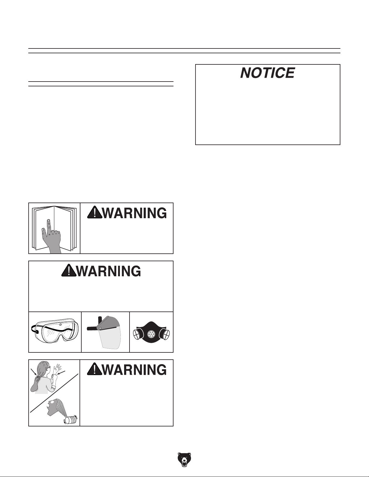
Eye and face injuries and respiratory problems can occur while operating this tool.
Wear personal protective equipment to
reduce your risk from these hazards.
-24-
jewelry away from mov-
severe crushing injuries!
Installs desired grinding attachment.
2.
3. Inspects and installs belt with appropriate grit
for operation.
Determines if operation requires parallel or
4.
perpendicular grinding and adjusts frame tilt
as necessary.
If installed, adjusts platen tilt as desired.
5.
6. Adjusts tool rest to support workpiece, if fea-
sible for operation, then adjusts tool rest to
allow maximum
and belt.
Ties back loose hair and clothing, and puts
7.
on safety glasses, respirator, and face shield.
Takes all other required safety precautions.
Starts machine and adjusts belt speed as
8.
desired.
Holds workpiece firmly with both hands, sup-
9.
ports it with fixtures as well as operation and
setup allow, pushes workpiece into belt, and
moves it to different locations to wear belt
evenly and to prevent it from overheating.
Stops machine when operation is complete.
10.
1
⁄16" clearance between rest
Model G0972 (Mfd. Since 10/23)
Page 27

Workpiece Inspection
Some workpieces are not suitable for grinding on a grinder. Before grinding, inspect all
workpieces for the following:
• Flammable Workpiece: Workpieces with
unstable chemical elements (like magnesium) may catch fire or create explosion
hazards when introduced to the heat and
friction of grinding. Be aware of the material
composition of workpieces you intend to use
and avoid grinding different metals and alloys
on the same belt in case two different materials create a dangerous chemical reaction.
• Soft Workpiece: Workpieces that are made
of aluminum, brass, lead, and other nonferrous metals will load up in the belt. Grinding
plastics, rubber, fiberglass, or other soft
materials can also cause the same problem.
Always use the recommended belt for the
material.
• Flexible/Unstable Workpiece: Grinding on
the side or the ends of cable, chain, or round
workpieces creates the hazard of workpiece
twist or grab, leading to contact with the belt.
This hazard must be avoided.
• Wood Workpiece: Never grind wood on
this machine. Wood dust and shavings are
extremely flammable and hot metal sparks
will ignite them. A belt that has been used
to sand wood creates a flame and explosion
hazard when the hot sparks created by grinding metal are introduced.
Grinding Tips
• Extend the life of the abrasive belt by regularly using an abrasive surface cleaner. Change
a belt when cleaning is no longer effective.
• As a rule-of-thumb, grind with progressively
higher grit numbers. A higher grit will achieve
a finer finish.
• Hold workpiece securely with both hands and
do not wear gloves. Use tool rest and jigs
whenever possible to support workpiece. Do
not force workpiece against belt.
• Never grind magnesium. Once shaved or
powdered, it is highly flammable, and a
magnesium fire is difficult to put out.
• Remember that grinding metal often produces sparks. DO NOT grind metal near flammable materials, and be aware of the area
around the machine the sparks will reach.
• Use full width of belt by moving the workpiece
back-and-forth across the belt.
• Make sure belt guards/covers are secured
during operation.
• The workpiece will get hot as you continue
to grind. Cool the workpiece frequently by
quenching in water or another approved
solution.
• Wear the proper protective clothing. Prepare
for particles to be expelled from the grinder
at high speeds. Wear safety glasses, face
shield, dust mask, earplugs, leather apron,
and heavy leather boots.
Model G0972 (Mfd. Since 10/23)
Moving belt can cause serious personal
injury if it comes in contact with fingers,
hands, or other body parts. Always support
workpiece against tool rest when grinding if
possible. Use extreme care to provide a safe
distance between belt and any body part.
-25-
Page 28
Choosing
Abrasive Belts
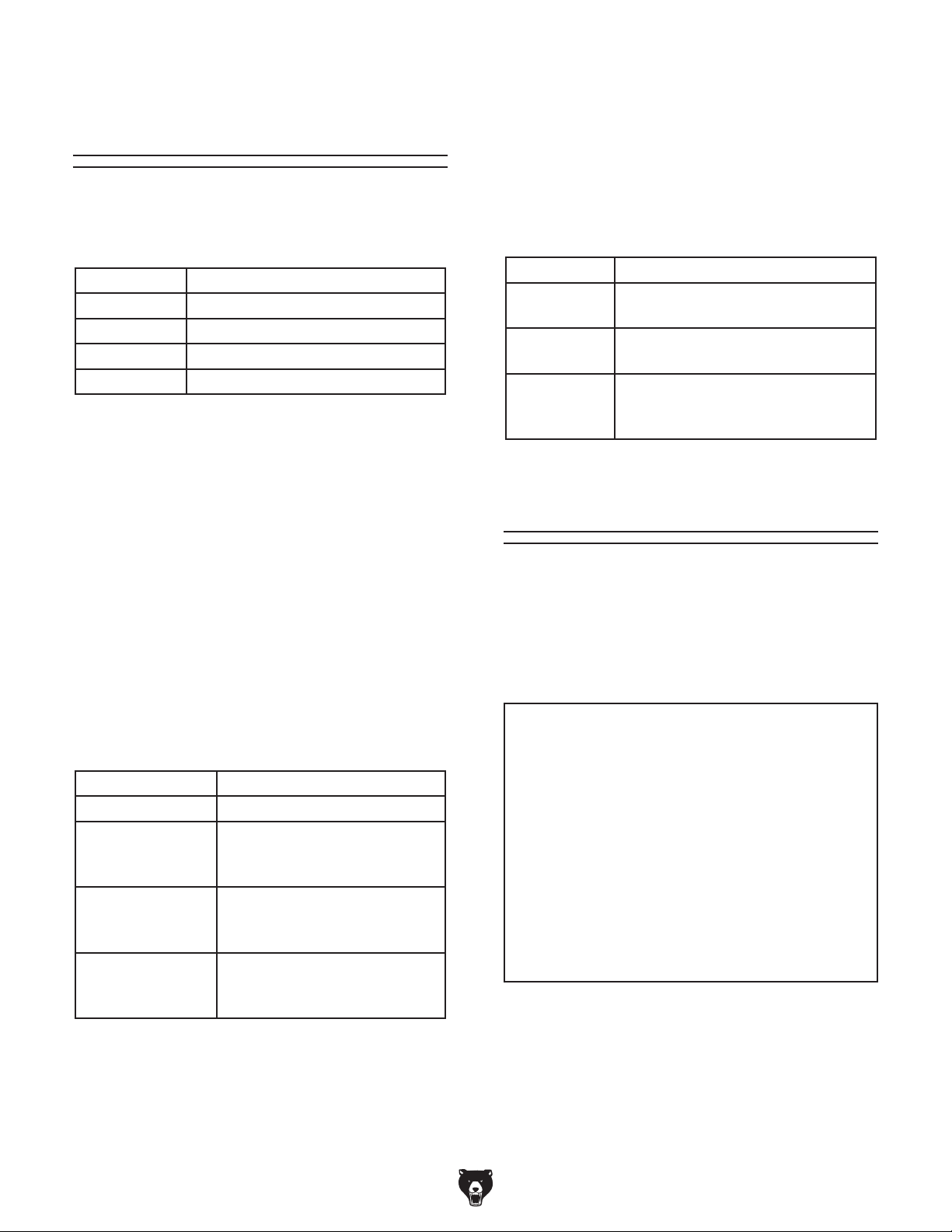
This machine uses a 3" x 783⁄4" belt. Below is a
chart that groups abrasives into different classes,
and shows which grits fall into each class.
Depending on the material, some belts also come
with different backing material. For grinding, cloth
backing is the most common and has various
weights. The "weight" of the cloth backing refers
to the flexibility of the belt, and you will want to use
a belt with flexibility tailored to your workpiece and
application. The chart below illustrates common
cloth weights and their flexibility/uses.
Grit Class
24–60 Extra Coarse
60 –120 Coarse
120–180 Medium
180+ Fine
The general rule of thumb is to grind a workpiece
with progressively higher grit numbers. Avoid
skipping grits; the larger the grit increase, the
harder it will be to remove the scratches from the
previous grit.
Ultimately, the type of metal you use and your
stage of finish will determine the best grit types to
install on your grinder.
Belts are also made with different materials,
and your workpiece and intended operation will
determine which belt material will produce the
best results for you. The following chart illustrates
some common belt materials and the situations
that they are most effective.
Belt Weight Description
J-Weight Flexible. Good for contour
sanding/grinding.
X-Weight Medium flexibility. Strong. For
all-purpose sanding/grinding.
Y-Weight Least flexible. Very strong. Good
for heavy stock removal. Often
waterproof and tear resistent.
Changing Frame Tilt
Change the upper machine frame to a vertical or
horizontal position, depending on your operation.
With the frame vertical, it is easier to perform
grinds perpendicular to the belt (i.e., with a
workpiece flat against the table in Figure 29).
Belt Material Operation
Aluminum Oxide Finishing. Ferrous metals.
Zirconia Alumina Finishing; wet or dry
grinding. Ferrous metals,
some steels.
Ceramic Aggressive grinding;
deburring. Heat-sensitive
metals.
Silicon Carbide Cutting; stock removal; wet
or dry grinding. Cast iron,
steel, non-ferrous metals.
-26-
Figure 29. Example of perpendicular grinding
with frame in vertical position.
Model G0972 (Mfd. Since 10/23)
Page 29
With the frame horizontal, it is easier to perform
grinds parallel to the belt (i.e., with a workpiece flat
against the tool rest in Figure 30).
— If changing frame to horizontal position,
upper frame will rest on (2) stud bumpers
shown in Figure 32.
Stud
Bumper
(1 of 2)
Figure 30. Example of parallel grinding with
frame in horizontal position.
Tool Needed Qty
Hex Wrench 6mm .............................................. 1
To change frame tilt:
DISCONNECT MACHINE FROM POWER!
1.
2. Remove (2) cap screws, lock washers, and
flat washers shown in Figure 31.
x 2
Figure 32. Location of horizontal support stud
bumpers.
— If changing frame to vertical position, cap
screws must go up through holes in lower
frame to secure upper machine frame (see
Figure 33).
Upper
Machine
Frame
x 2
Figure 33. Upper machine frame in vertical
position.
Figure 31. Location of vertical lock screws
(frame shown in horizontal position).
Tilt frame to vertical or horizontal position,
3.
then re-install fasteners removed in Step 2.
Model G0972 (Mfd. Since 10/23)
Grinding forces and machine vibration are
powerful and could tip unsecured upper
machine frame. Failure to secure upper
machine frame to lower machine frame
when upper machine frame is in vertical
position could result in loss of control and
serious personal injury.
-27-
Page 30
Tracking Belt
— If belt tracks centered on wheels and
grinding attachment, proceed to Step 6.
You must perform the following procedure after
installing an abrasive belt to ensure that the belt
does not come off the wheels or get jammed
against the belt frame.
To track belt:
DISCONNECT MACHINE FROM POWER!
1.
2. Tie back loose clothing and long hair to pro-
tect yourself from getting caught in moving
belt during following steps.
Standing in front of machine, push belt mul-
3.
tiple times along installed grinding attachment so it moves in direction of operation
(see Figure 34), then watch how belt tracks
on wheels and grinding attachment.
— If belt does not track centered on wheels
and grinding attachment, proceed to
Step 4.
Adjust hex nut on belt tracking knob away
4.
from machine frame (see Figure 35).
Use belt tracking knob (see Figure 35) to
5.
adjust belt tracking while continuing to rotate
belt by hand to check adjustment.
— Turn knob clockwise to move belt left on
wheels, and turn knob counterclockwise to
move belt right on wheels.
Belt
Tracking
Knob
Figure 34. Belt direction of operation (contact
wheel grinding attachment installed).
Figure 35. Belt tracking components.
Connect machine to power supply.
6.
7. Start machine and verify that belt is tracking
correctly in center of wheels. Fine-tune tracking with belt tracking knob as necessary while
machine is running.
Adjust hex nut on belt tracking knob without
8.
moving knob so it contacts frame to secure
tracking setting.
-28-
Model G0972 (Mfd. Since 10/23)
Page 31
Installing
Contact Wheel
4. Loosen attachment arm lock handles (see
Figure 37) and remove abrasive belt from
wheels and any installed attachment arms.
Grinding Attachment
Whenever you install the contact wheel grinding
attachment on your machine, install and track the
belt before proceeding with operations.
To install contact wheel:
DISCONNECT MACHINE FROM POWER!
1.
2. Adjust frame tilt so frame is vertical (refer to
Changing Frame Tilt on Page 26).
Turn belt tension crank (see Figure 36) about
3.
five turns clockwise. This will stretch tension
spring to release abrasive belt tension.
Note: Tension spring will wear with use.
Increase number of crank turns as needed to
fully release belt tension.
Belt Tension
Crank
Attachment
Arm Lock
Handle
(1 of 6)
Figure 37. Location of attachment arm lock
handles.
5. Insert contact wheel grinding attachment arm
into upper arm slot (see Figure 38).
Install abrasive belt around wheels, center-
6.
ing belt on wheels and being sure arrows
on abrasive belt match rotation arrow on
machine (see Figure 38).
Abrasive Belt
Abrasive Belt
Figure 36. Location of belt tension crank.
Model G0972 (Mfd. Since 10/23)
Contact Wheel
Grinding Attachment
Figure 38. Contact wheel grinding attachment
and abrasive belt installed.
Belt Rotation
Arrow
-29-
Page 32
Move contact wheel as far forward as you
7.
can without stretching belt (see Figure 39),
then tighten upper slot lock handles.
Upper Slot
Lock Handle
(1 of 2)
Contact
Wheel
10.
Insert table arm into middle arm slot (see
Figure 41).
Adjust table so there is no more than 1⁄16"
11.
between table and belt, then tighten (2)
middle slot lock handles to secure (see
Figure 41).
Maximum
1
⁄16" Gap
Figure 39. Contact wheel moved forward.
8. Turn belt tension crank counterclockwise until
rubber pad (see Figure 40) on end of crank
no longer presses against machine frame.
This will release spring tension and tension
belt.
Rubber
Pad
Figure 40. Location of rubber pad on belt
tension crank.
Middle Slot
Lock Handle
Table Arm
(1 of 2)
Figure 41. Table arm in middle arm slot.
Install spark trap on (2) magnets on under-
12.
side of table arm, as shown in Figure 42.
Spark Trap
Figure 42. Spark trap installed on table arm.
9. Refer to Tracking Belt on Page 28 to
ensure abrasive belt tracks correctly on contact wheel, idler wheel, and drive wheel.
-30-
Model G0972 (Mfd. Since 10/23)
Page 33
Adjusting Table Tilt
The table should be used whenever it can feasibly be installed to help support the workpiece
when grinding against the contact wheel. Once
installed, it can be safely tilted from 0–45° (see
Figure 43).
Table
Contact Wheel
Grinding
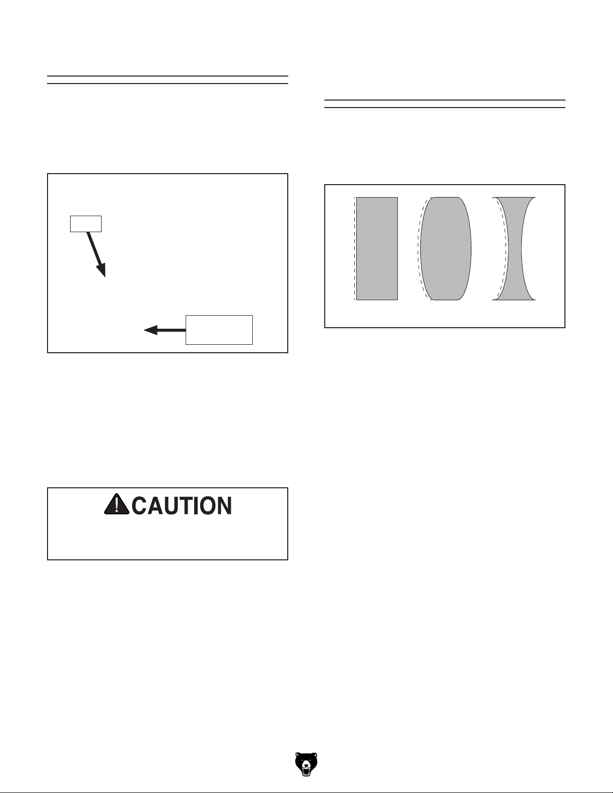
While the platen grinding attachment can only be
used for flat or convex workpieces, the contact
wheel grinding attachment allows for workpieces
that are concave (see Figure 44).
Table Tilt
Lock Handle
Figure 43. Table tilted.
When grinding very thin workpieces, a common practice when producing knife bevels, the
workpiece can be drawn into the gap between the
table and the belt. If a workpiece is too thin to be
safely supported by the table, consider researching freehand belt grinding techniques or using a
different method to grind your workpiece.
Table must always be adjusted within 1⁄16" of
belt to reduce risk of fingers or workpiece
being drawn into gap.
To adjust table tilt:
Flat
Figure 44. Workpiece surface types.
The contact wheel is also good for aggressively
removing material, grinding profiles, and creating
hollow grinds.
Regardless of your workpiece, always use two
hands to control the workpiece and use the table
to support the workpiece, if feasible.
To grind on contact wheel:
DISCONNECT MACHINE FROM POWER!
1.
2. Refer to Installing Pipe Notching
Attachments on Page 36 to install profile
roller and pipe vise.
Adjust frame tilt, as desired (refer to Changing
3.
Frame Tilt on Page 26).
Convex Concave
DISCONNECT MACHINE FROM POWER!
1.
2. Loosen table tilt lock handle (see Figure 43),
adjust table tilt between 0–45º, then tighten
handle to secure.
Model G0972 (Mfd. Since 10/23)
-31-
Page 34
Adjust table tilt, as desired (refer to Adjusting
4.
Table Tilt on Page 31), then ensure table
is within
Connect machine to power, turn it ON, and
5.
adjust machine to desired speed.
Position workpiece on table, if installed.
6.
1
⁄16" of belt.
Installing Platen
Grinding Attachment
Whenever you install the platen grinding attachment on your machine, install and track the belt
before proceeding with operations.
7. Use both hands to maintain control of
workpiece, as shown in Figure 45, and slowly feed it into contact wheel with light, even
pressure. DO NOT force workpiece against
belt.
Note: There are many different techniques
for using belt to grind and sharpen knives.
Whichever one you use, make sure that you
hold knife firmly and ease it into belt without
excessive pressure to ensure safe operation.
Tools Needed Qty
Hex Wrench 6mm .............................................. 1
Wrench or Socket 13mm
To install platen grinding attachment:
DISCONNECT MACHINE FROM POWER!
1.
2. Adjust frame tilt so frame is vertical (refer to
Changing Frame Tilt on Page 26).
Turn belt tension crank (see Figure 46) about
3.
five turns clockwise. This will stretch tension
spring to release abrasive belt tension.
Note: Tension spring will wear with use.
Increase number of crank turns as needed to
fully release belt tension.
................................... 1
Belt Tension
Crank
Figure 45. Feeding workpiece correctly.
-32-
Figure 46. Location of belt tension crank.
Model G0972 (Mfd. Since 10/23)
Page 35
4. Loosen attachment arm lock handles (see
Figure 47) and remove abrasive belt from
wheels and any installed attachment arms.
Abrasive Belt
Move platen as far forward as you can with-
7.
out stretching belt (see Figure 49), then
tighten (2) upper slot lock handles.
Upper Slot
Lock Handles
Attachment Arm
Lock Handle
(1 of 6)
Figure 47. Location of attachment arm lock
handles.
5. Insert platen grinding attachment arm into
upper arm slot (see Figure 48).
Install abrasive belt around wheels and plat-
6.
en, centering belt on wheels and being sure
arrows on abrasive belt match rotation arrow
on machine (see Figure 48).
Abrasive Belt
Platen
Figure 49. Platen moved forward.
8. Turn belt tension crank counterclockwise until
rubber pad (see Figure 50) on end of crank
no longer presses against machine frame.
This will release spring tension and tension
belt.
Rubber
Pad
Platen Grinding
Attachment
Figure 48. Platen grinding attachment and
abrasive belt installed.
Model G0972 (Mfd. Since 10/23)
Belt Rotation
Arrow
Figure 50. Location of rubber pad on belt
tension crank.
9. Refer to Tracking Belt on Page 28 to
ensure abrasive belt tracks correctly on platen wheels, idler wheel, and drive wheel.
-33-
Page 36
10. Insert table arm into lower arm slot (see
Figure 51).
Install spark trap on (2) magnets on under-
11.
side of table arm, as shown in Figure 51.
Position table arm as needed to line up spark
12.
trap with platen, as shown in Figure 51, then
tighten (2) lower slot lock handles to secure.
Table
Arm
Adjusting Platen Tilt
Tilt the platen up to 45° if necessary for your
operation (see Figure 53).
Platen
Platen Tilt
Lock Handle
Lower Slot
Lock Handles
Figure 51. Table arm and spark trap installed.
— If table prevents you from adjusting spark
trap as needed, remove table from arm
(see Figure 52).
Figure 52. Table removed from table arm.
Spark
Trap
Figure 53. Platen tilted to 45°.
To adjust platen tilt:
DISCONNECT MACHINE FROM POWER!
1.
2. Loosen platen tilt lock handle (see Figure
53), adjust platen tilt between 0–45º, then
tighten handle to secure.
Platen Grinding
The platen grinding attachment is good for flat
grinding, material removal, and creating profiles.
Regardless of your workpiece, always use two
hands to control the workpiece and use the tool
rest to support the workpiece, if feasible.
Tools Needed Qty
Hex Wrench 6mm .............................................. 1
Wrench or Socket 13mm
................................... 1
-34-
Model G0972 (Mfd. Since 10/23)
Page 37
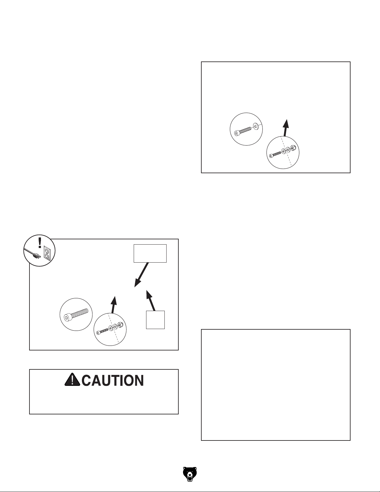
To grind on platen:
DISCONNECT MACHINE FROM POWER!
1.
2. Refer to Installing Platen Grinding
Attachment on Page 32 to install platen
grinding attachment.
Adjust frame tilt, as desired (refer to Changing
3.
Frame Tilt on Page 26).
Adjust platen tilt, as desired (refer to Adjusting
4.
Platen Tilt).
Position workpiece on tool rest to check if tool
5.
rest support is feasible for operation.
— If tool rest can be used for operation,
loosen (2) cap screws shown in Figure
1
54, adjust tool rest until it is within
⁄16" of
belt, then tighten cap screws to secure.
Proceed to Step 8.
Remove (2) cap screws, (3) flat washers, and
6.
(1) lock nut shown in Figure 55 to remove
tool rest.
Figure 55. Location of tool rest fasteners.
7. Re-install front cap screw, (2) flat washers,
and (1) lock nut.
Note: One of the cap screws has a lock
nut securing it.
Maximum
1
⁄16" Gap
Tool
Rest
Figure 54. Tool rest clearance components.
Tool rest must always be adjusted within
1
⁄16" of belt to reduce risk of fingers or
workpiece being drawn into gap.
Connect machine to power, turn it ON, then
8.
adjust machine to desired speed.
Use both hands to maintain control of
9.
workpiece, as shown in Figure 56, and slowly feed it into platen with light, even pressure.
DO NOT force workpiece against belt.
Note: There are many different techniques
for using belt to grind and sharpen knives.
Whichever one you use, make sure that you
hold knife firmly and ease it into belt without
excessive pressure to ensure safe operation.
— If tool rest must be removed for operation,
proceed to Step 6.
Model G0972 (Mfd. Since 10/23)
Figure 56. Feeding workpiece correctly.
-35-
Page 38
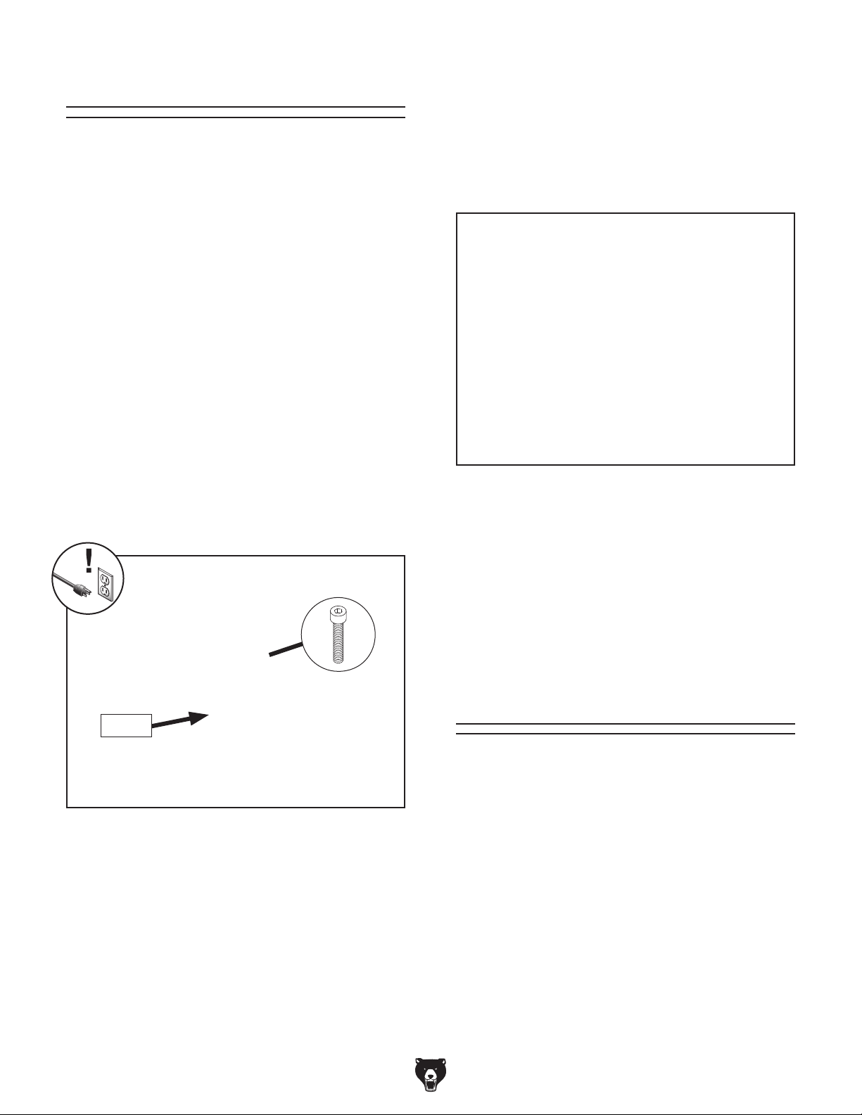
Slack Belt Grinding
Slack belt grinding operations are performed
directly on the belt with the platen grinding attachment installed, but the platen is removed.
When a workpiece is fed into the belt without a
flat platen behind it, the belt can better conform to
curved contours.
Tools Needed Qty
Hex Wrenches 5, 6mm ................................1 Ea.
Wrench or Socket 13mm
To slack belt grind:
1. DISCONNECT MACHINE FROM POWER!
2. Refer to Installing Platen Grinding
Attachment on Page 32 to install platen
grinding attachment.
................................... 1
Use both hands to maintain control of
7.
workpiece, as shown in Figure 58, and
slowly feed it into moving belt with light, even
pressure. DO NOT force workpiece against
belt. Move workpiece to different locations to
wear abrasive belt evenly and to prevent it
from overheating.
Figure 58. Example of slack belt grinding.
Loosen (2) cap screws shown in Figure 57,
3.
then slide platen back to remove.
x 2
Platen
Figure 57. Location of platen and fasteners.
4.
Perform Steps 6–7 of Platen Grinding on
Page 35.
Adjust frame tilt, as desired (refer to Changing
5.
Frame Tilt on Page 26).
8.
When slack grinding is complete, install plat-
en and refer to Adjusting Platen to Wheels
on Page 45 to adjust platen correctly to
resume platen grinding operations.
Installing
Pipe Notching
Attachments
Whenever you install the profile roller notching
attachment on your machine, install and track the
belt before proceeding with operations.
To install pipe notching attachments:
DISCONNECT MACHINE FROM POWER!
1.
2. Adjust frame tilt so frame is vertical (refer to
Changing Frame Tilt on Page 26).
Connect machine to power, turn it ON, and
6.
adjust machine to desired speed.
-36-
Model G0972 (Mfd. Since 10/23)
Page 39
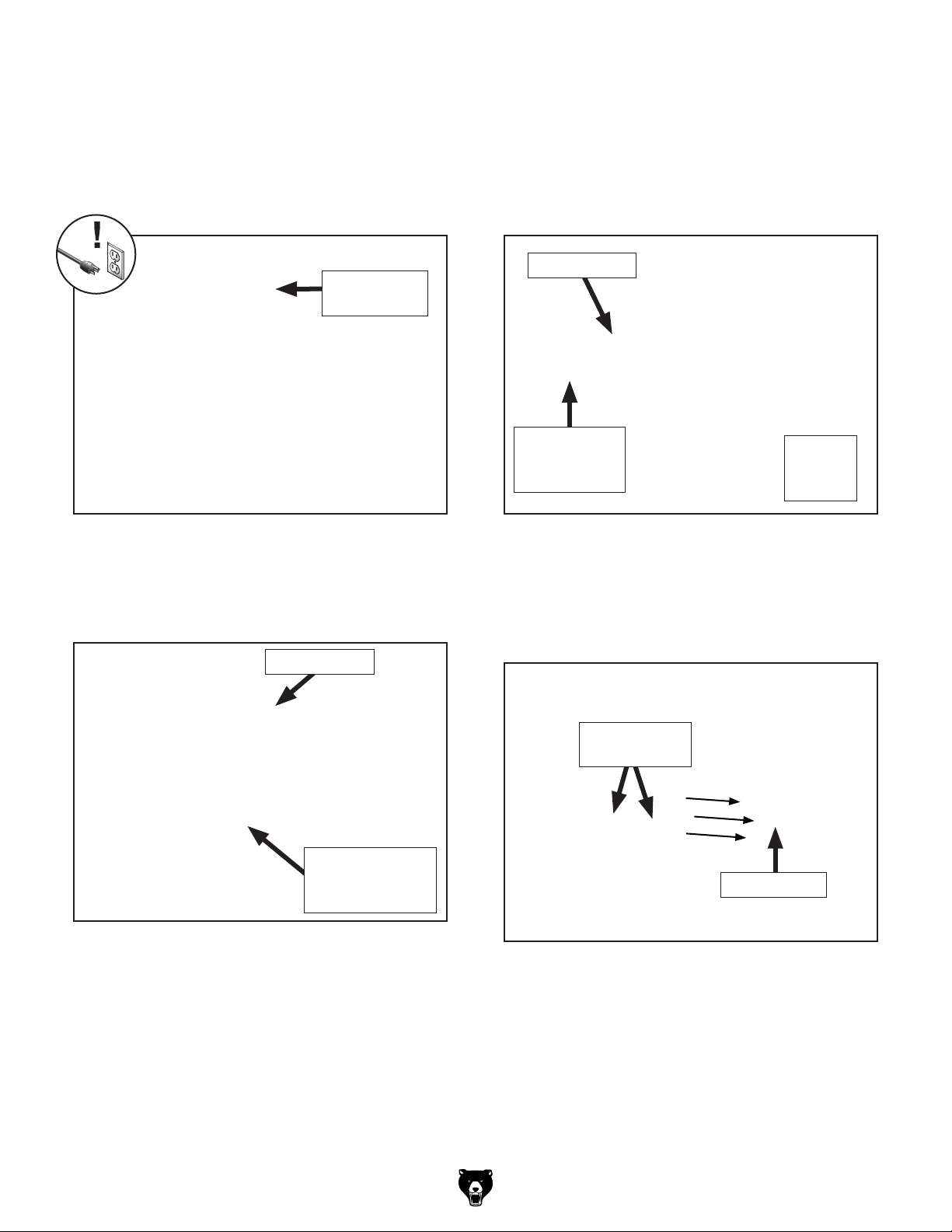
Turn belt tension crank (see Figure 59) about
3.
five turns clockwise. This will stretch tension
spring to release abrasive belt tension.
Note: Tension spring will wear with use.
Increase number of crank turns as needed to
fully release belt tension.
Belt Tension
Crank
5. Insert profile roller notching attachment arm
into upper arm slot (see Figure 61).
Install abrasive belt around wheels and roller,
6.
centering belt on wheels and being sure
arrows on abrasive belt match rotation arrow
on machine (see Figure 61).
Abrasive Belt
Figure 59. Location of belt tension crank.
Loosen attachment arm lock handles (see
4.
Figure 60) and remove abrasive belt from
wheels and any installed attachment arms.
Abrasive Belt
Attachment Arm
Lock Handle
(1 of 6)
Profile Roller
Notching
Attachment
Figure 61. Profile roller notching attachment and
abrasive belt installed.
7. Move profile roller as far forward as you can
without stretching belt (see Figure 62), then
tighten (2) upper slot lock handles.
Upper Slot
Lock Handles
Profile Roller
Belt
Rotation
Arrow
Figure 60. Location of attachment arm lock
handles.
Model G0972 (Mfd. Since 10/23)
Figure 62. Profile roller moved forward.
-37-
Page 40
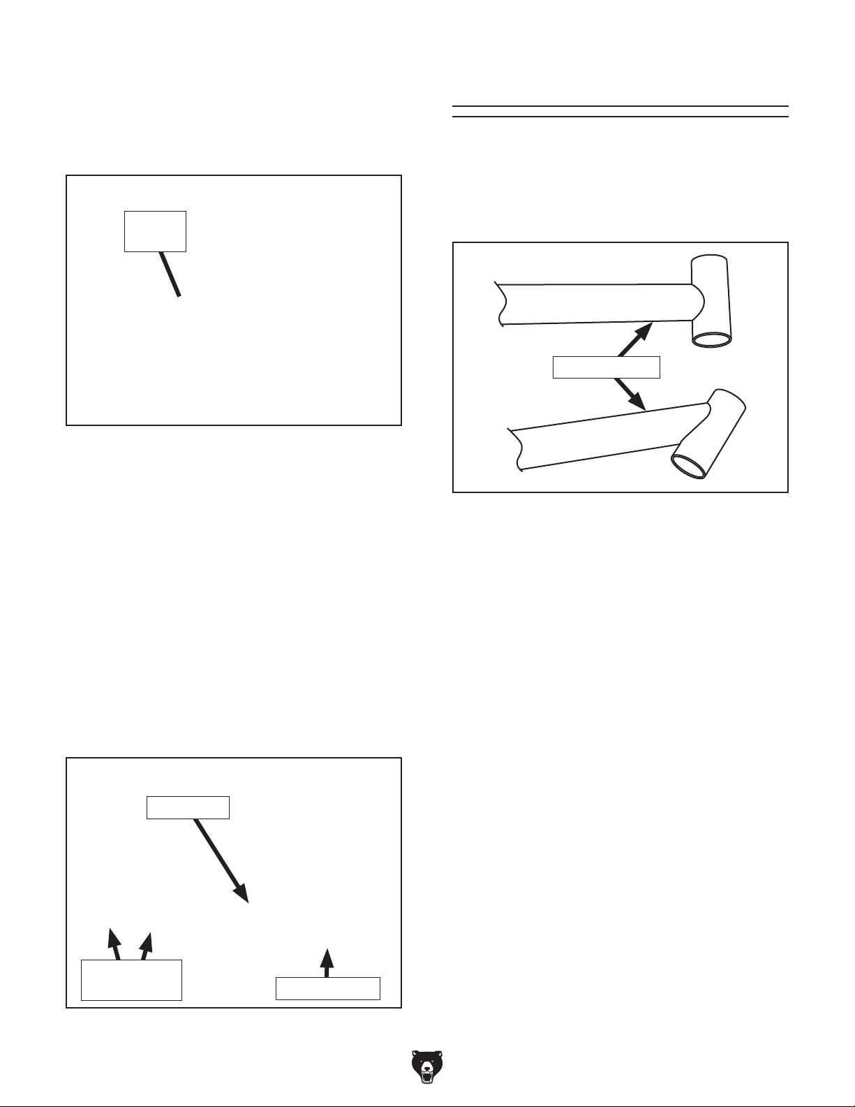
8. Turn belt tension crank counterclockwise until
rubber pad (see Figure 63) on end of crank
no longer presses against machine frame.
This will release spring tension and tension
belt.
Rubber
Pad
Figure 63. Location of rubber pad on belt
tension crank.
Pipe Notching
The pipe notching attachments convert the knife
grinder into an abrasive pipe notcher that can
quickly notch or cope the ends of metal pipes (see
Figure 65), so two pieces of pipe can be welded
together with clean, strong joints.
Notched Pipes
9.
Refer to Tracking Belt on Page 28 to
ensure abrasive belt tracks correctly on profile roller, idler wheel, and drive wheel.
Insert pipe vise arm into lower arm slot (see
10.
Figure 64).
Install spark trap on (2) magnets on pipe vise
11.
arm, as shown in Figure 64.
Position pipe vise arm as needed to line up
12.
spark trap with platen, as shown in Figure
64, then tighten (2) lower slot lock handles to
secure.
Spark Trap
Figure 65. Examples of fitting notched pipes.
The pipe vise position and angle can be adjusted
in relation to the profile roller, and it is mounted
on slide shafts so you can smoothly feed the
workpiece into the roller. Always use two hands to
feed the vise and workpiece into the roller.
The Model G0972 comes with a 0.964" (24.48mm)
profile roller. Refer to ACCESSORIES on Page
40 for a set of rollers with a variety of sizes.
Tool Needed Qty
Hex Wrench 6mm .............................................. 1
To notch pipe:
DISCONNECT MACHINE FROM POWER!
1.
2. Refer to Installing Pipe Notching
Attachments on Page 36 to install profile
roller and pipe vise.
Lower Slot
Lock Handles
Figure 64. Pipe vise arm and spark trap
installed.
-38-
Pipe Vise Arm
Make sure pipe end to be notched is smooth-
3.
ly cut without any burrs.
Adjust frame tilt so frame is vertical (refer to
4.
Changing Frame Tilt on Page 26).
Model G0972 (Mfd. Since 10/23)
Page 41
Move pipe vise on slide shafts away from
5.
profile roller (see Figure 66).
— If workpiece is aligned with profile roller,
vise position does not need to be adjusted. Proceed to Step 10.
Profile Roller
Pipe
Vise
Slide Shaft
(1 of 2)
Figure 66. Pipe vise in starting position on slide
shafts.
Turn vise leadscrew handle counterclockwise
6.
to open vise jaws enough to fit workpiece
between them (see Figure 67).
Insert workpiece between vise jaws, mak-
7.
ing sure workpiece extends far enough forward in vise that notching operation can be
performed without vise contacting belt (see
Figure 67), then turn vise leadscrew handle
clockwise until workpiece is secure.
— If workpiece is not aligned with profile roll-
er when fed forward, proceed to Step 9.
Loosen (2) cap screws shown in Figure 68,
9.
adjust vise position on cross slide bracket so
workpiece is aligned with profile roller, then
tighten cap screws to secure.
Vise Angle
Lock Handle
Cross Slide
Bracket
Figure 68. Vise position and angle adjustment
components.
10. Connect machine to power, turn it ON, and
adjust machine to desired speed.
x 2
Workpiece
Vise
Leadscrew
Vise Jaw
(1 of 2)
Figure 67. Pipe secured in vise jaws.
8. Loosen vise angle lock handle (see Figure
68), rotate vise to desired angle of notch (in
relation to profile roller), then tighten lock
handle to secure.
Handle
Use both hands to maintain control of vise,
11.
as shown in Figure 69, and slowly feed
workpiece into profile roller with light, even
pressure. DO NOT force workpiece against
belt.
Figure 69. Feeding workpiece correctly.
Model G0972 (Mfd. Since 10/23)
-39-
Page 42
SECTION 5: ACCESSORIES
Installing unapproved accessories may
order online at www.grizzly.com or call 1-800-523-4777
cause machine to malfunction, resulting in
serious personal injury or machine damage.
To reduce this risk, only install accessories
recommended for this machine by Grizzly.
NOTICE
Refer to our website or latest catalog for
additional recommended accessories.
Zirconia Belts
Zirconia alumina belts are great for finishing and
can be used for wet or dry grinding.
T34019—3" x 79" 40-Grit, 5-Pk.
T34020—3" x 79" 60-Grit, 5-Pk.
T34021—3" x 79" 80-Grit, 5-Pk.
T34022—3" x 79" 100-Grit, 5-Pk.
T34023—3" x 79" 120-Grit, 5-Pk.
T34024—3" x 79" Assorted Grits, 5-Pk.
Silicon Carbide Belts
Silicon carbide belts are great for removing stock
and can be used for wet or dry grinding.
T34025—3" x 79" 40-Grit, 5-Pk.
T34026—3" x 79" 60-Grit, 5-Pk.
T34027—3" x 79" 80-Grit, 5-Pk.
T34029—3" x 79" 120-Grit, 5-Pk.
T34031—3" x 79" 180-Grit, 5-Pk.
T34032—3" x 79"
T34033—3" x 79" 400-Grit, 5-Pk.
T34034—3" x 79" 600-Grit, 5-Pk.
T34035—3" x 79" Assorted Grits, 5-Pk.
220-Grit, 5-Pk.
T34062—Pipe Grinding Rollers, 6-Pc.
This set includes six stainless steel, ball bearing rollers for the versatility you need to cope
common pipe diameters. Sizes include: 0.465"
(11.81mm), 0.715" (18.16mm), 1.465" ( 37. 2 1m m),
1.965" (49.91mm), 2.465" (62.61mm), and 2.965"
(75.31mm).
Figure 70. T34062 Pipe Grinding Rollers.
T32720—10" Variable-Speed Wet Sharpener
The 220-grit aluminum oxide grinding wheel
is specially made for wet sharpening and runs
through a water bath to prevent residue buildup
on the grinding wheel and keep tools cool while
sharpening. The leather stropping wheel helps
remove burrs and hones to a final razor edge.
Ceramic Belts
Ceramic belts are great for aggressive grinding
and deburring.
T34036—3" x 79" Assorted Grits, 5-Pk.
Figure 71. T32720 10" Variable-Speed Wet
Sharpener.
-40-
Model G0972 (Mfd. Since 10/23)
Page 43
SECTION 6: MAINTENANCE
To reduce risk of shock or
accidental startup, always
disconnect machine from
Wear ANSI-approved safety goggles and
NIOSH-approved respirator while cleaning
and emptying spark trap to protect against
power before adjustments,
maintenance, or service.
Schedule
airborne particles disturbed by cleaning.
For optimum performance from this machine, this
maintenance schedule must be strictly followed.
Ongoing
To minimize your risk of injury and maintain proper
machine operation, shut down the machine immediately if you ever observe any of the items below,
and fix the problem before continuing operations:
• Loose mounting bolts.
• Debris in spark trap.
• Worn or damaged belt.
Damaged tension spring.
•
Worn or damaged wires.
•
Any other unsafe condition.
•
Daily Maintenance
• Clean any shavings and dust from between
platen and belt.
Weekly Maintenance
• Sweep surrounding dust and shavings.
• Clean/vacuum dust off motor.
• Clean and protect profile roller.
Monthly Maintenance
• Lubricate frame tilt hinges.
• Clean and lubricate vise slide shafts and
leadscrew.
Cleaning &
Protecting
Vacuum excess shavings, and wipe off any
remaining dust with a dry cloth. Never use compressed air to blow away dust as airborne particles may be combustible.
Wipe the profile roller clean with disposable rags
and mineral spirits. When dry, apply a light coat of
a rust preventative.
Emptying Spark Trap
Remove the spark trap and any accumulated
dust, then replace the spark trap. Do not store the
dust near heat or anything likely to produce spark,
as some types of metal dust can be flammable.
If you are not disposing of the collected metal dust
immediately, keep it in an approved, closed-top
metal container stored away from fire hazards
until you are ready to do so.
Model G0972 (Mfd. Since 10/23)
-41-
Page 44
Replacing Belts
A belt should be replaced whenever there is a
noticeable change in quality/performance. Refer
to ACCESSORIES on Page 40 for belts with a
variety of materials and grit sizes that fit the Model
G0972. Lower grits will provide a finer finish while
higher grits will supply quick material removal.
3
Required Belt Size............................ 3" x 78
⁄4"
Lubrication
Vise Slide Shafts
Oi l Ty pe ................ SB1365 or ISO 68 Equivalent
Oil Amount
Lubrication Frequency
Items Needed Qty
Disposable Rags ............................... As Needed
Mineral Spirits
Move the vise as necessary to access the full
length of the slide shafts (see Figure 73) and
clean any debris from their surfaces with rags and
mineral spirits. When dry, wipe slide shafts with
ISO 68 oil using a clean shop rag.
............................................Thin Coat
.........40 Hrs. of Operation
.................................... As Needed
The bearings on the Model G0972 are sealed
and permanently lubricated; they require no lubrication. The parts that require lubrication are the
frame tilt hinges, the vise slide shafts, and the
vise leadscrew.
DISCONNECT MACHINE FROM POWER
BEFORE PERFORMING LUBRICATION!
Frame Tilt Hinges
Oi l Ty pe .................T26685 or ISO 32 Equivalent
Oil Amount
Lubrication Frequency
Apply a couple drops of an ISO 32 oil weekly to
each frame tilt hinge (see Figure 72). Adjust the
upper machine frame through its full tilting range
to distribute the oil.
.......................................... 3–5 Drops
.........40 Hrs. of Operation
Vise
Leadscrew
Vise Slide Shaft
(1 of 2)
Figure 73. Location of vise lubrication
components.
Vise Leadscrew
Oi l Ty pe ................ SB1365 or ISO 68 Equivalent
Oil Amount
Lubrication Frequency
Items Needed Qty
Stiff Brushes ...................................................... 2
Mineral Spirits
............................................Thin Coat
.........40 Hrs. of Operation
.................................... As Needed
Frame Tilt Hinges
Figure 72. Location of frame tilt hinges.
-42-
Move the adjustable vise jaw as necessary in
order to access the vise leadscrew (see Figure
73) to clean any debris from the threads with a
stiff brush and mineral spirits. When dry, apply a
thin coat of ISO 68 oil and work the lubricant into
the threads with a clean, stiff brush. Wipe away
any excess oil. Move the adjustable vise jaw
through the full length of movement to distribute
the oil.
Model G0972 (Mfd. Since 10/23)
Page 45
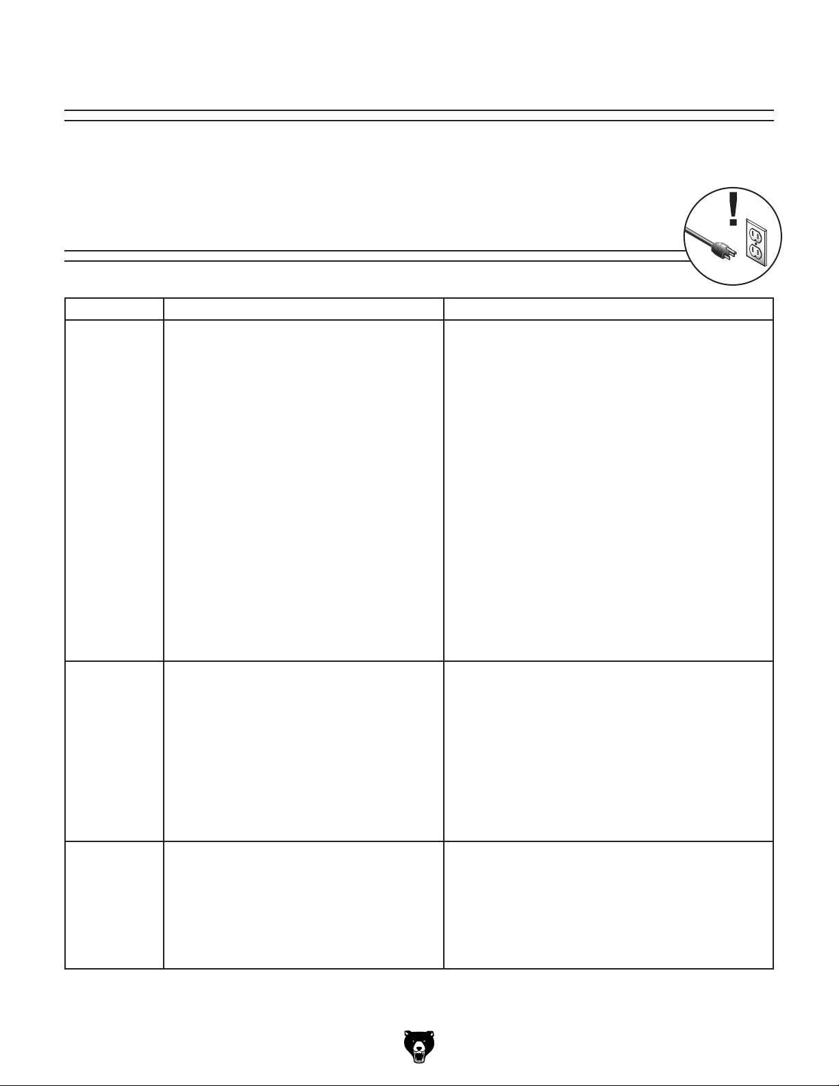
Review the troubleshooting procedures in this section if a problem develops with your machine. If you need
replacement parts or additional help with a procedure, call our Technical Support.
the
serial number and manufacture date of your machine before calling.
SECTION 7: SERVICE
Troubleshooting
Motor & Electrical
Symptom Possible Cause Possible Solution
Machine does
not start, or
power supply
breaker
immediately
trips after
startup.
Machine
stalls or is
underpowered.
Machine has
vibration or
noisy operation.
1. Master power switch in OFF position.
2. Stop or EMERGENCY STOP button
depressed.
3. Machine circuit breaker(s) tripped or at fault.
4. Incorrect power supply voltage or circuit size.
5. Potentiometer at fault.
6. Power supply circuit breaker tripped or fuse
blown.
7. Motor wires connected incorrectly.
8. Wiring broken, disconnected, or corroded.
9. ON/OFF switch, Stop button, or
EMERGENCY STOP button at fault.
10. Circuit breaker or relay at fault.
11. Transformer at fault.
12. Braking resistor at fault.
13. VFD at fault.
14. Motor or motor bearings at fault.
1. Excessive workpiece pressure.
2. Wrong workpiece material (metal).
3. Motor wires connected incorrectly.
4. Machine undersized for task.
5. Motor overheated.
6. Tripped machine circuit breaker(s).
7. Extension cord too long.
8. Motor or motor bearings at fault.
1. Motor or component loose.
2. Machineisincorrectlymountedtooor.
3. Drive wheel cap screw missing or loose.
4. Motor fan rubbing on fan cover.
5. Motor bearings at fault.
1. Turn master power switch to ON position.
2. Rotate button head to reset.
3. Reset circuit breaker(s).
4. Ensure correct power supply voltage and circuit size
(Page 12).
5. Test/replace if at fault.
6. Ensure circuit is free of shorts. Reset circuit breaker or
replace fuse.
7. Correct motor wiring connections (Page 46).
8. Fix broken wires or disconnected/corroded
connections (Page 46).
9. Replace switch/button.
10. Replace relay/circuit breaker.
11. Inspect transformer; replace if at fault.
12. Test/replace if at fault.
13. Inspect VFD; replace if at fault.
14. Replace motor.
1. Reduce workpiece pressure against belt.
2. Use correct type/size of metal.
3. Correct motor wiring connections (Page 46).
4. Clean/replace (Page 42) belt; reduce feed rate/
grinding depth.
5. Clean motor, let cool, and reduce workload.
6. Reset breaker(s).
7. Move machine closer to machine power supply; use
shorter extension cord (Page 13).
8. Replace motor.
1. Replace damaged or missing bolts/nuts or tighten if
loose.
2. Shim base or tighten mounting hardware.
3. Inspect drive wheel. Replace or tighten if necessary.
4. Fix/replace fan cover; replace loose/damaged fan.
5. Test by rotating shaft; rotational grinding/loose shaft
requires bearing replacement.
Note: Please gather
Model G0972 (Mfd. Since 10/23)
-43-
Page 46
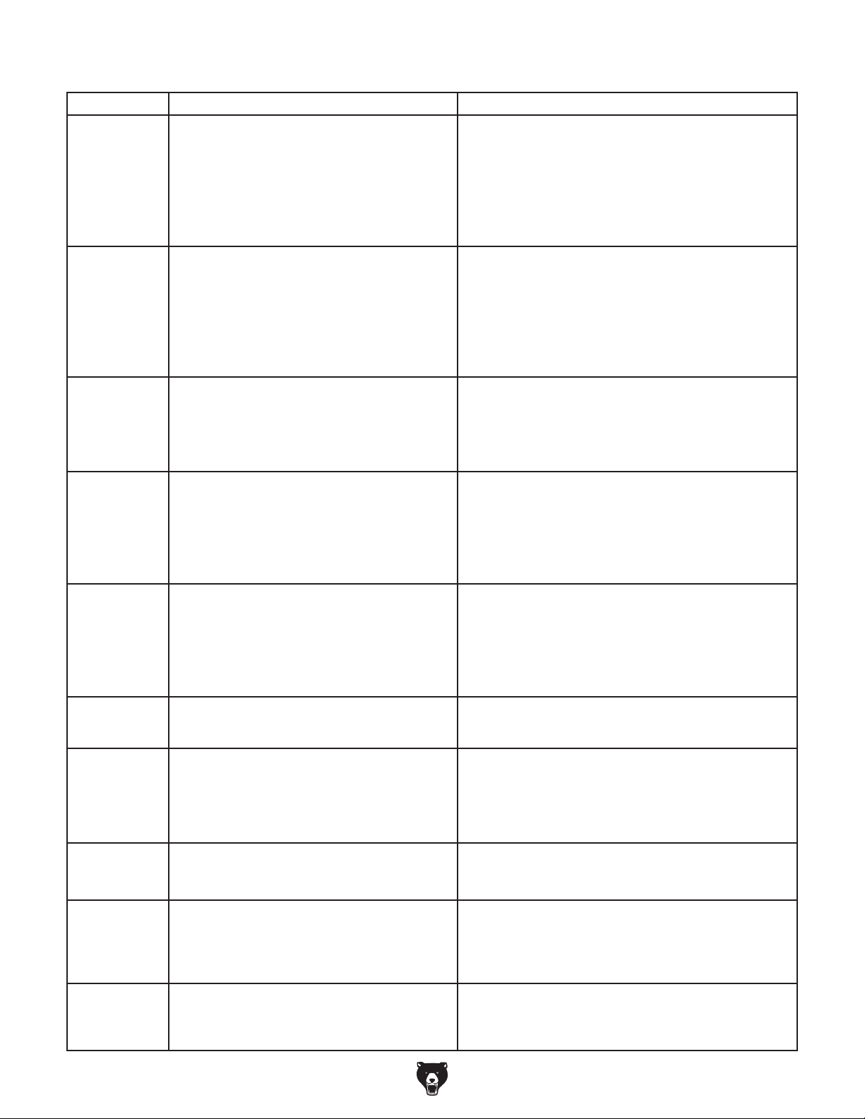
Operation
Symptom Possible Cause Possible Solution
Belt slaps
or vibrates
excessively.
Belt will not
track properly.
Belt slips during
use.
Belt clogs
quickly.
Deep grooves
or scores in
workpiece.
Poor, nonaggressive
grinding results.
Abrasive grit
rubs off belt
easily.
Excessive belt
replacement.
Workpiece
surface is not
square when
platen tilt is set
to 0º.
Workpiece
frequently gets
pulled out of
your hands.
1. Belt is not tensioned properly.
2. Belt tracking needs adjustment.
3. Broken/defective belt.
4. Idler or drive wheel is loose.
5. Extension spring is worn/at fault.
1. Belt is not tensioned properly.
2. Belt tracking needs adjustment.
3. Belt is stretched, unevenly worn, or damaged.
4. Tracking assembly bent or crooked.
5. Extension spring is worn/at fault.
1. Belt is not tensioned properly.
2. Excessive workpiece pressure.
3. Extension spring is worn/at fault.
1. Excessive belt speed.
2. Worn belt.
3. Excessive workpiece pressure.
4. Usingtooneofbeltgrit.
5. Workpiece material is prone to belt clogging,
such as aluminum.
1. Excessive belt speed.
2. Using too coarse of belt grit.
3. Excessive workpiece pressure.
4. Workpiece held still for too long.
5. Graphite pad on platen damaged.
1. Belt clogged/worn.
2. Usingtooneofbeltgrit.
1. Belt stored in incorrect environment.
2. Belt has been folded or crushed.
3. Belt is too old.
1. Not using full width of abrasive surface.
2. Excessive workpiece pressure.
1. Platen not perpendicular to tool rest. 1. Use machinist square to adjust platen tilt so it is
1. Not supporting workpiece properly.
2. Starting workpiece on a leading corner.
1. Adjust installed grinding attachment forward while belt
tension is disengaged, lock grinding attachment, then
tension belt.
2. Adjust belt tracking (Page 28).
3. Replace belt (Page 42).
4. Tighten idler or drive wheel.
5. Replace extension spring.
1. Adjust installed grinding attachment forward while belt
tension is disengaged, lock grinding attachment, then
tension belt.
2. Adjust belt tracking (Page 28).
3. Replace belt (Page 42).
4. Replace bent or crooked tracking components.
5. Replace extension spring.
1. Adjust installed grinding attachment forward while belt
tension is disengaged, lock grinding attachment, then
tension belt.
2. Reduce workpiece pressure against belt.
3. Replace extension spring.
1. Decrease belt speed.
2. Replace belt (Page 42).
3. Reduce workpiece pressure against belt.
4. Use coarser grit belt (Page 26).
5. Reduce feed pressure. Use coarser grit belt
(Page 26).
1. Decrease belt speed.
2. Usenergritbelt(Page 26).
3. Reduce workpiece pressure against belt.
4. Move workpiece back and forth across abrasive
surface.
5. Replace graphite pad on platen.
1. Clean/replace (Page 42) belt.
2. Use coarser grit belt (Page 26).
1. Replace damaged belt (Page 42); store belt in cool,
dry area.
2. Replace damaged belt (Page 42).Storebeltat;do
not bend or fold belt.
3. Use new belt (Page 42).
1. Move workpiece back and forth across abrasive
surface.
2. Reduce workpiece pressure against belt.
perpendicular to tool rest.
1. Use tool rest (Page 34) or table (Page 31) to
support workpiece.
2. Start workpiece on a trailing corner.
-44-
Model G0972 (Mfd. Since 10/23)
Page 47
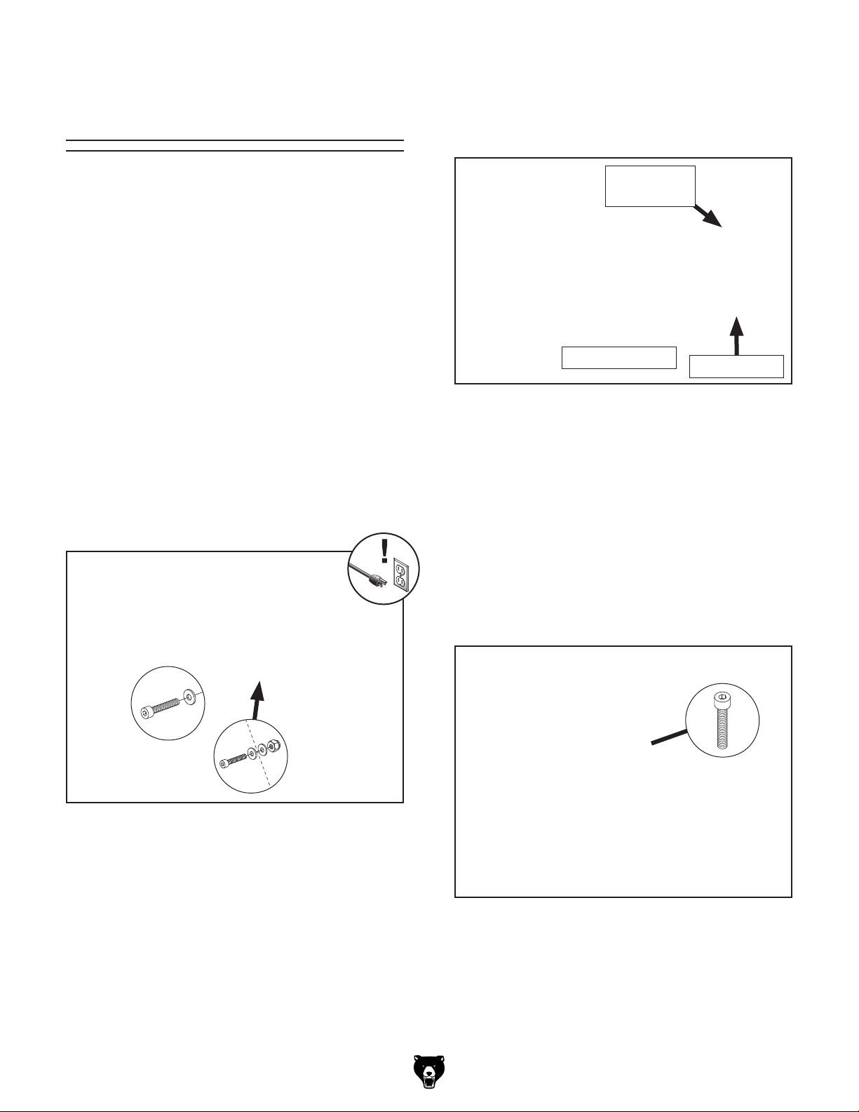
Adjusting
Platen to Wheels
6.
Place straightedge across platen graphite
and idler wheels, as shown in Figure 75, and
measure distance between each idler wheel
and straightedge.
The platen should extend about
the two idler wheels on the platen grinding attachment in order to produce flat and square grinds.
Due to the force and abrasives of grinding, the
platen wears as it is used, so you will occasionally need to adjust the platen forward in order for
grinds to maintain this adjustment.
Tools Needed Qty
Hex Wrenches 5, 6mm ................................1 Ea.
Wrench or Socket 13mm
Straightedge 12"
To adjust platen to wheels:
DISCONNECT MACHINE FROM POWER!
1.
2. Remove (2) cap screws, (3) flat washers, and
(1) lock nut shown in Figure 74 to remove
tool rest.
................................................ 1
................................... 1
1
⁄8" forward from
Idler Wheel
(1 of 2)
Platen Graphite
Figure 75. Example of checking distance
between platen graphite and idler wheels.
— If each idler wheel is approximately 1⁄8"
from straightedge, platen does not need to
be adjusted.
— If each idler wheel is not approximately 1⁄8"
from straightedge, proceed to Step 7.
Straightedge
Figure 74. Location of tool rest fasteners.
Re-install front cap screw, (2) flat washers,
3.
and (1) lock nut.
Remove abrasive belt.
4.
Adjust frame tilt so frame is horizontal (refer
5.
to Changing Frame Tilt on Page 26).
Loosen (2) cap screws shown in Figure 76,
7.
adjust platen so each idler wheel is about
from straightedge, then tighten screws.
x 2
Figure 76. Location of platen adjustment cap
screws.
1
⁄8"
Model G0972 (Mfd. Since 10/23)
-45-
Page 48
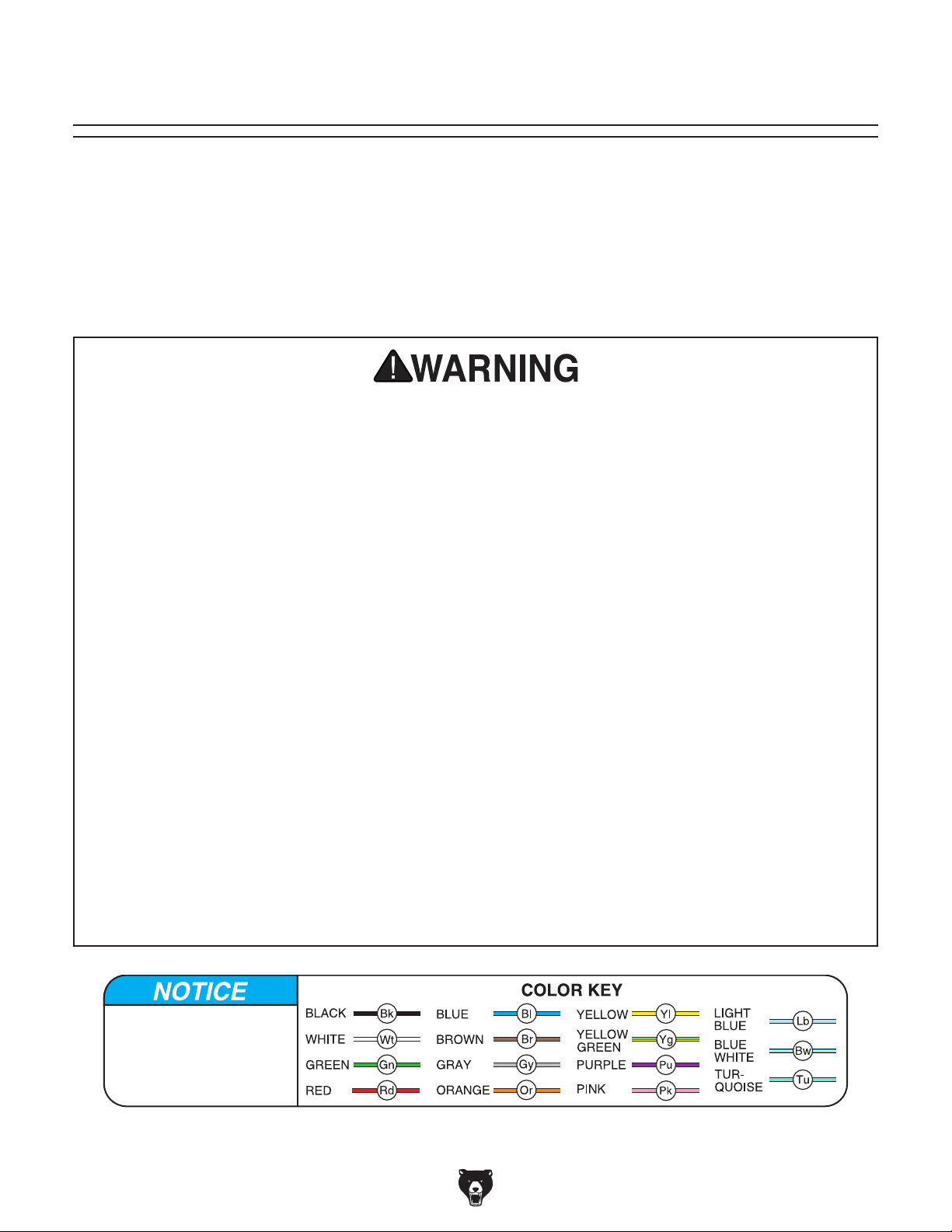
These pages are current at the time of printing. However, in the spirit of improvement, we may make changes to the electrical systems of future machines. Compare the manufacture date of your machine to the one
stated in this manual, and study this section carefully.
If there are differences between your machine and what is shown in this section, call Technical Support at
(570) 546-9663 for assistance BEFORE making any changes to the wiring on your machine. An updated
wiring diagram may be available.
number and manufacture date of your
machine before calling. This information can be found on the main machine label.
SECTION 8: WIRING
Note: Please gather the serial
Wiring Safety Instructions
SHOCK HAZARD. Working on wiring that is con-
nected to a power source is extremely dangerous.
Touching electrified parts will result in personal
injury including but not limited to severe burns,
electrocution, or death. Disconnect the power
from the machine before servicing electrical components!
MODIFICATIONS. Modifying the wiring beyond
what is shown in the diagram may lead to unpredictable results, including serious injury or fire.
This includes the installation of unapproved aftermarket parts.
WIRE CONNECTIONS. All connections must
be tight to prevent wires from loosening during
machine operation. Double-check all wires disconnected or connected during any wiring task to
ensure tight connections.
CIRCUIT REQUIREMENTS. You MUST follow
the requirements at the beginning of this manual
when connecting your machine to a power source.
WIRE/COMPONENT DAMAGE. Damaged wires
or components increase the risk of serious personal injury, fire, or machine damage. If you notice
that any wires or components are damaged while
performing a wiring task, replace those wires or
components.
MOTOR WIRING. The motor wiring shown in
these diagrams is current at the time of printing
but may not match your machine. If you find this
to be the case, use the wiring diagram inside the
motor junction box.
CAPACITORS/INVERTERS. Some capacitors
and power inverters store an electrical charge for
up to 10 minutes after being disconnected from
the power source. To reduce the risk of being
shocked, wait at least this long before working on
capacitors.
EXPERIENCING DIFFICULTIES. If you are experiencing difficulties understanding the information
included in this section, contact our Technical
Support at (570) 546-9663.
The photos and diagrams
included in this section are
best viewed in color. You
can view these pages in
color at www.grizzly.com.
-46-
Model G0972 (Mfd. Since 10/23)
Page 49
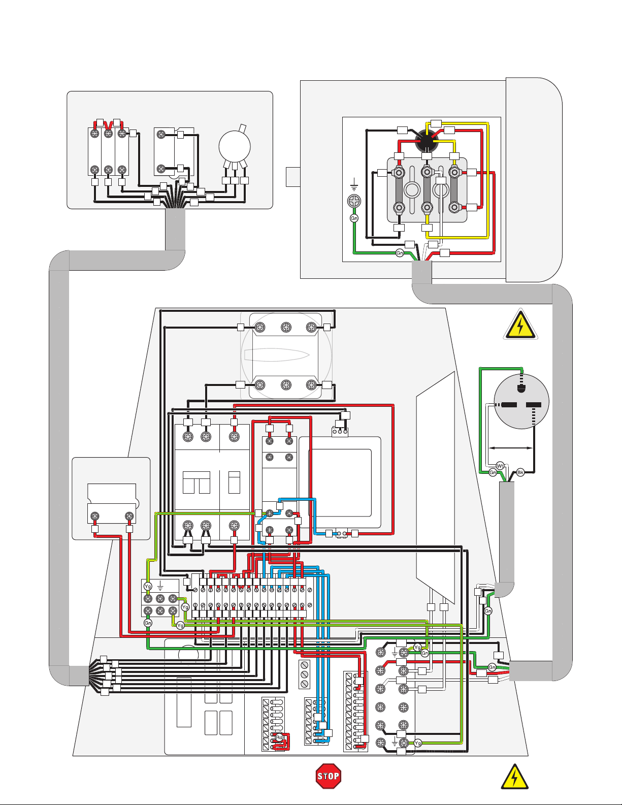
CONTROL PANEL
Wiring Diagram
ON/OFF Switch
XINDALI
SDL16-EBW8465
5
5
2
1
0
6
5
3
4
4
STOP Button
GOCHENG
XB2-ES542
1 2NC
5
4
0
6
2
3
3
2
12
11
Potentiometer
UXCELL
WH118
12
11
10
10
ELECTRICAL CABINET
N
Master Power
JFD11-25(KG25B)
N1
Switch
JUCHE
L1L2L3
T1T2T3
MOTOR 220V
U2
V1
V1 U1
U1
U2
U1
V1
W2
U1
V1
W2
6-15 Plug
Ground
G
V2
W1
GND
L
L1
W1
W1
V2 U2 W2
V2
W1
EMERGENCY
STOP Button
GOCHENG
XB2-ES542
1 2NC
4
3
2
3
4
5
6
0
10
11
12
L1
Circuit Breakers
JUCHE DZ47-63
C16
L2
N
L
L N 2 3 3 4 4 5 6 0 10 11 12 13 14
N
L
VFD
DELTA VFD11AMS21ANSAA
1
N1
C2
2
N2
2
2
5310
4
3
4
5310
4
4
3
MCM
SGND
DCM
+24V
SG–
SG+
0
0
6
6
S2
S1
13
8
Relay
GOCHENG
GB2N-GS
0
12
14
0
11
12
0
11
12
4
5
14
1314
6
9
5
13
13
RC
RB
RA
MO2
MO1
AFM
ACI
AVI
ACM
+10V
Transformer
COD.045/90 30VA
14
14
10
11
12
TTMC
0
DFM
DCM
DCM
+24V
+24V
L2
N2
Hot Hot
220 VAC
Braking
Resistor
300W 70Ω
1
N
16
W1
V1
14
MI7
MI6
MI5
MI4
MI3
13
MI2
MI1
U1
DC– DC+/+1 +2/B1 B2
N2
R/L1 S/L2 T/L3 U/T1 V/T2 W/T3
L2
15
16
15
L
W1
V1
U1
Model G0972 (Mfd. Since 10/23)
READ ELECTRICAL SAFETY
ON PAGE 46!
-47-
Page 50

Electrical Components
Figure 77. Control panel wiring.
Figure 78. Motor junction box wiring.
Figure 79. EMERGENCY STOP button wiring.
-48-
READ ELECTRICAL SAFETY
ON PAGE 46!
Figure 80. Master power switch and electrical
cabinet wiring.
Model G0972 (Mfd. Since 10/23)
Page 51
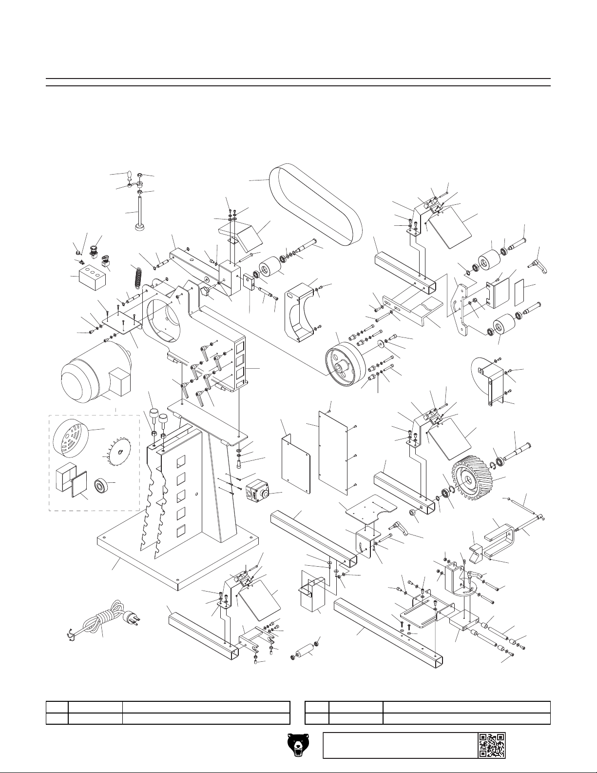
89
SECTION 9: PARTS
We do our best to stock replacement parts when possible, but we cannot guarantee that all parts shown
are available for purchase. Call (800) 523-4777 or visit www.grizzly.com/parts to check for availability.
2 P0972002 HEX NUT M12-1.75 4 P0972004 E-STOP BUTTON GOCHENG XB2-ES542
Main
106
105
14
12
6
107
109
7
11-2
110
11-3
112
48
108
15
1
44
17
104
16
11
11-1
11-4
15
13
2
2
23
19
18
8
3
2
81
21
20
25
23
56
15
27
9
25
57
111
28
62
82
58
29
24
30
7
6
103
59
26
10
60
31
21
5
61
85
22
45
33
63
7
86
80
32
4
101
6
46
102
64
34
84
23
83
36
70
35
47
39
65
25
66
20
87
77
38
80
57
72
25
23
71
7
7
41
42
37
6
57
7
56
25
23
49
68
7
69
7
7
89
88
101
40
50
89
102
58
62
58
94
62
67
59
60
61
63
32
34
73
20
52
93
7
60
61
63
52
99
97
95
67
79
59
53
51
9
7
90
32
91
31
76
74
67
75
78
25
23
43
55
54
100
98
96
56
92
91
REF P ART # DES CRIPTION REF PART # DESCRIP TION
1 P0972001 STA ND 3 P0972003 BUMPER M12.175 X 50
Model G0972 (Mfd. Since 10/23)
BUY PARTS ONLI NE AT GRIZZLY.COM!
Scan QR code to visit our Parts Store.
-49-
Page 52
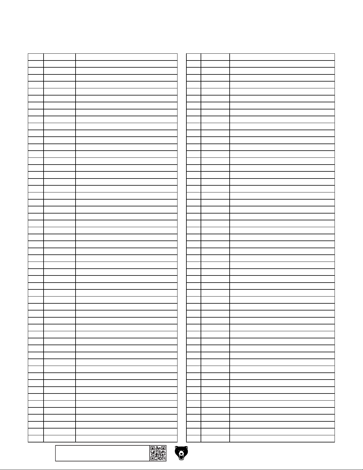
56 P0972056 EYE SHIELD BRACKET (WHEEL) 112 P0972112 POWER CORD 14G 3W 98" 6-15P
Main Parts List
REF PART # DE SCRIP TION REF P ART # DE S CRIP TI ON
5 P0972005 CAP SCREW M8-1.25 X 25 57 P0972057 EYE SHELD SEAT
6 P0972006 LOCK WASHER 8MM 58 P0972058 PHLP HD SCR M5-.8 X 8
7 P0972007 FLA T WASHE R 8MM 59 P0972059 CAP SCREW M5-.8 X 60
8 P0972008 ADJUSTABLE HANDLE M8-1.25 X 25, 63L 60 P0972060 PHLP HD SCR M4-.7 X 12
9 P0972009 HEX NUT M8-1 . 2 5 61 P0972061 EYE SHIELD CLAMP
10 P0972010 UPPER FRA ME 62 P0972062 HE X NUT M4- . 7
11 P0972011 MOTOR 3HP 220V 3-PH 63 P0972063 EYE SHIELD
11-1 P0972011-1 MOTOR FAN CO VER 64 P0972064 TABLE ARM
11-2 P0972011-2 MOTOR FAN 65 P0972065 TABLE
11-3 P0972011-3 JUNCTI ON BO X 66 P0972066 TABLE MOUNT
11-4 P0972011-4 BALL BEARING 6206ZZ 67 P0972067 ADJUSTABLE HANDLE M8-1.25 X 20, 63L
12 P0972012 CAP SCREW M8-1.25 X 10 68 P0972068 CAP SCREW M8-1.25 X 70
13 P0972013 CONTROL P ANEL MOUNT 69 P0972069 CAP SCREW M6-1 X 8
14 P0972014 CONTROL PANEL 70 P0972070 SPARK TRAP
15 P0972015 EXT RETA I NI NG RI NG 1 2MM 71 P0972071 PLATEN ARM
16 P0972016 TENSION SHAFT LOWER 72 P0972072 EYE SHIELD BRACKET (PLATEN)
17 P0972017 EXTENSION SPRING 3.5 X 28 X 122 73 P0972073 PLATE N FRAME
18 P0972018 TENSION SHAFT UPPER 74 P0972074 I DLER WHEEL SHAFT
19 P0972019 TENSION BRACKET 75 P0972075 PLATEN
20 P0972020 LOCK NUT M8-1.25 76 P0972076 CAP SCREW M6-1 X 12
21 P0972021 CAP SCREW M8-1.25 X 12 77 P0972077 CAP SCREW M8-1.25 X 85
22 P0972022 TENSION WHEEL COVER 78 P0972078 GRAPHITE PAD 3" X 5-1/8"
23 P0972023 FLAT WAS HER 6MM 79 P0972079 TOOL REST
24 P0972024 LOCK WASHER 6MM 80 P0972080 CAP SCREW M8-1.25 X 20
25 P0972025 CAP SCREW M6-1 X 10 81 P0972081 NO TCHI NG ROLL ER ARM
26 P0972026 FLAT HD CAP SCR M8-1.25 X 90 82 P0972082 ROLLER BRACKET
27 P0972027 KNOB BOLT M10-1.5 X 50, 5-LOBE, D50 83 P0972083 BALL BEARING 608ZZ
28 P0972028 HEX NUT M10 -1. 5 84 P0972084 ROLLER 0.964" STEEL
29 P0972029 TRACKING BLOCK 85 P0972085 SET SCREW M10-1.5 X 17 BALL-POINT
30 P0972030 PIVOT SHAFT 86 P0972086 HE X NUT M10 -1. 5 THI N
31 P0972031 BALL BEARING 6003ZZ 87 P0972087 PIPE VISE ARM
32 P0972032 IDLER WHEEL 88 P0972088 CROSS SLIDE BRACKET
33 P0972033 FLAT WAS HER 12 MM 89 P0972089 CAP SCREW M8-1.25 X 16
34 P0972034 EXT RETA I NI NG RI NG 1 7MM 90 P0972090 SLI DE BLOCK
35 P0972035 TENSION WHEEL SHAFT 91 P0972091 SPACER 8 X 15 X 24MM
36 P0972036 DRIVE WHEEL COVER REAR 92 P0972092 SLI DE SHAFT
37 P0972037 CAP SCREW M8-1.25 X 50 93 P0972093 SHOULDER BOLT M16-2 X 10, 8 X 8
38 P0972038 ADJUSTING SLEEVE 94 P0972094 FIXED VISE J AW
39 P0972039 DRIVE WHEEL 95 P0972095 ADJUSTABLE VISE JAW
40 P0972040 CAP SCREW M10-1.5 X 30 96 P0972096 SET SCREW M6-1 X 10
41 P0972041 LOCK WASHER 10MM 97 P0972097 VI SE BRACKET
42 P0972042 FLAT WASHER 10.5 X 40 X 5MM 98 P0972098 VI SE LEADSCREW
43 P0972043 DRIVE WHEEL COVE R FRONT 99 P0972099 HA NDLE RO D END M8- 1. 25
44 P0972044 TENSION SHAFT W/PAD 100 P0972100 HA NDLE RO D
45 P0972045 ELECTRI CAL MOUNTI NG BO ARD 101 P0972101 FLAT HD SCR M5-. 8 X 12
46 P0972046 ELECTRICAL PANEL 102 P0972102 MAGNET
47 P0972047 PHLP HD SCR M5-.8 X 10 103 P0972103 PHLP HD SCR M4-.7 X 6
48 P0972048 TENSI ON CRANK 104 P0972104 ON/OFF SWITCH XINDALI SDL16-EBW8465
49 P0972049 CONTACT WHEE L ARM 105 P0972105 POTENTIOMETER UXCELL WH118
50 P0972050 LOCK NUT M16-2 106 P0972106 VARIABLE-SPEED DIAL
51 P0972051 EXT RETA I NI NG RI NG 2 0MM 107 P0972107 SET SCREW M4-.7 X 6 SLOTTED
52 P0972052 BALL BEARING 6004ZZ 108 P0972108 STOP BUTTON GOCHENG XB2-ES542
53 P0972053 INT RETA I NI NG RING 42MM 109 P0972109 PHLP HD SCR M4-.7 X 8
54 P0972054 CONTACT WHEE L 110 P0972110 REVOLVING HANDLE 20 X 74, M8-1.25 X 70
55 P0972055 CONTACT WHEE L SHA FT 111 P0972111 BELT 3" X 79" 80-GRIT (5-PK)
-50-
BUY PARTS ONLI NE AT GRIZZLY.COM!
Scan QR code to visit our Parts Store.
Model G0972 (Mfd. Since 10/23)
Page 53
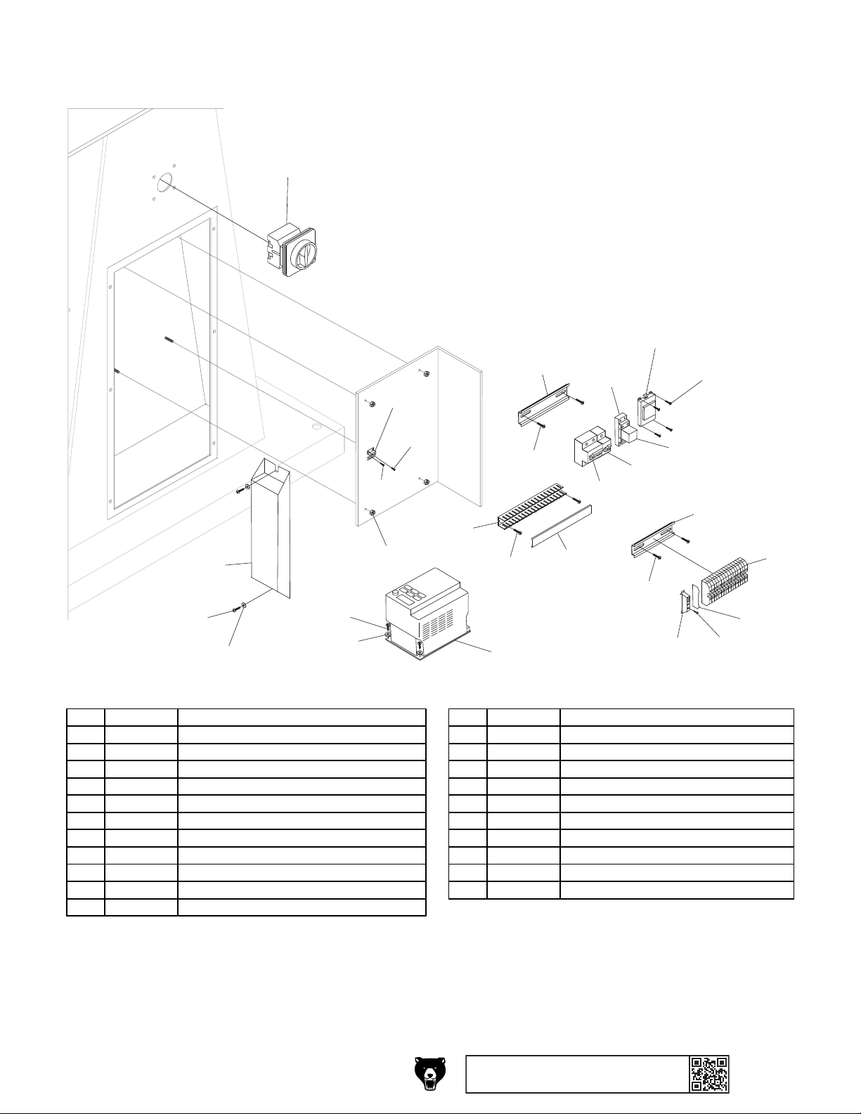
208
215
Electrical Cabinet
212 P0972212 BRAKING RESISTOR 300W 70OHM
201
206
221
204
205
218
205
205
205
222
203
223
209
220
212
202
205
219
211
205
207
REF P ART # DESCRI PTION REF P ART # DESCRI PTION
201 P0972201 POWER SWITCH JUCHE JFD11-25(KG25B) 213 P0972213 PHLP HD SCR M4-.7 X 12
202 P0972202 HEX NUT M6- 1 214 P0972214 FLAT WAS HER 4MM
203 P0972203 RELAY GOCHENG GB2N-GS 215 P0972215 VFD DELTA VFD11AMS21ANSAA
204 P0972204 RELAY HOLDER GOCHENG BGF-08A-E 216 P0972216 TERMINAL BLOCK END COVER
205 P0972205 PHLP HD SCR M4-.7 X 6 217 P0972217 TAP SCREW M2.9 X 13
206 P0972206 TRANSFORMER TTMC COD. 0 45/ 90 3 0VA 218 P0972218 TERMINAL BAR 3P M4 X 6 TM4
207 P0972207 PHLP HD SCR M5-.8 X 8 219 P0972219 WIRE LOOM COVER
208 P0972208 FLAT WAS HER 5MM 220 P0972220 WIRE LOOM 25 X 150 X 30MM
209 P0972209 DIN RAIL 35 X 100 221 P0972221 DIN RAIL 80 X 150
210 P0972210 TERMINAL BLOCK END STOP 222 P0972222 CIRCUI T BREAKER J UCHE DZ47 -63 C16
211 P0972211 TERMINAL BAR 16P DIN35 20-14G 223 P0972223 CIRCUI T BREAKER J UCHE DZ47 -63 C2
213
214
210
216
217
Model G0972 (Mfd. Since 10/23)
BUY PARTS ONLI NE AT GRIZZLY.COM!
Scan QR code to visit our Parts Store.
-51-
Page 54
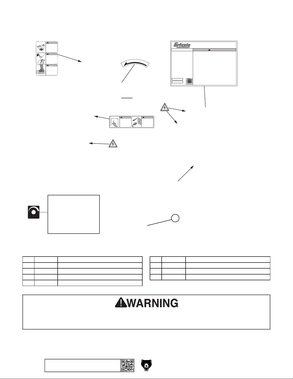
301
303
Labels & Cosmetics
305 P0972305 ELECTRICITY LABEL
WARNING!
EYE/LUNG
INJURY HAZARD!
Always wear
ANSI-approved safety
glasses, face shield, and
respirator when using
this machine.
WARNING!
ENTANGLEMENT
HAZARD!
Tie back long hair, roll up
long sleeves, and remove
loose clothing, jewelry, or
gloves to prevent getting
caught in moving parts.
WARNING!
INJURY
HAZARD!
DO NOT touch
moving sanding
belt, or personal
injury may occur!
305
WARNING!
To reduce risk of death
or serious injury, read
manual BEFORE using
machine.
To get a new manual, call
(800) 523-4777 or go to
www.grizzly.com.
302
T
L
E
B
306
R
O
T
304
A
T
I
O
N
WARNING!
INJURY/SHOCK
HAZARD!
Disconnect power
before adjustments,
maintenance, or
service.
305
Specifications
Power Req.: 220V, Single-Phase, 60 Hz
Motor: 3 HP, 220V, 3-Phase, 60 Hz
Full-Load Current Rating: 11A
Sanding Belt Size: 3" x 78-3/4"
Sanding Belt Speed: 1021–5768 FPM
Sanding Belt Tilt: 0°, 90°
Platen Tilt: 0–45°
Table Tilt: 0–45°
Drive Wheel Diameter: 7-7/8"
Platen Size: 5-1/4" x 4"
Weight: 276 lbs.
Date
S/N
Mfd. for Grizzly in China
MODEL G0972
3" X 78" KNIFE-MAKING GRINDER
To reduce risk of serious personal injury when using this machine:
1. Read and understand owner ’s manual before operating.
2. Always wear approved eye protection and respirator.
3. Only plug power cord into a grounded outlet.
4. Support workpiece with tool rest or table.
5. Maintain 1/16" maximum clearance between tool rest or table and sandpaper.
6. Do not set up machine for operations not recommended in owner ’s manual.
Adjusting platen or table tilt beyond recommended range increases risk of
workpieces or fingers being drawn into belt rotation.
7. Never touch moving sandpaper.
8. Always grind in accordance with directional arrows on machine.
9. Make sure machine is properly assembled, adjusted, and stable before
operating. Only operate with all guards in place.
10. Never grind pointed stock with point facing into belt rotation, and never
force workpiece into grinding surface.
11. Do not grind in flammable environment or near combustibles.
12. Only remove jammed pieces when sandpaper is stopped.
13. Disconnect power before changing sandpaper, adjusting, or servicing.
14. Do not wear loose clothing, gloves, jewelry, or other articles that can get
entangled. Tie back long hair and roll up sleeves.
15. Never reach over moving sanding belt.
16. Do not expose to rain or use in damp locations.
17. Do not operate under influence of drugs or alcohol, or when tired.
18. Prevent unauthorized use by children or untrained users; restrict access or
disable machine when unattended.
WARNING!
G0972
307
309
526 2350
308
REF PART # DESCRI P TION RE F P ART # DE SCRIP TI ON
301 P0972301 VERTICAL COMBO WARNING LABEL 306 P0972306 HORIZONTAL COMBO WARNING LABEL
302 P0972302 BELT ROTATION LABEL 307 P0972307 MODEL NUMBER LABEL
303 P0972303 MACHINE ID LABEL 308 P0972308 TOUCH-UP PAINT, GRIZZLY BEIGE
304 P0972304 TOUCH-UP PAINT, GRIZZLY GREEN 309 P0972309 VARIABLE-SPEED LABEL
Safety labels help reduce the risk of serious injury caused by machine hazards. If any label comes
off or becomes unreadable, the owner of this machine MUST replace it in the original location
before resuming operations. For replacements, contact (800) 523-4777 or www.grizzly.com.
-52-
BUY PARTS ONLI NE AT GRIZZLY.COM!
Scan QR code to visit our Parts Store.
Model G0972 (Mfd. Since 10/23)
Page 55

WARRANTY & RETURNS
Grizzly Industrial, Inc. warrants every product it sells for a period of 1 year to the original purchaser from
the date of purchase. This warranty does not apply to defects due directly or indirectly to misuse, abuse,
negligence,accidents,repairsoralterationsorlackofmaintenance.ThisisGrizzly’ssolewrittenwarranty
and any and all warranties that may be implied by law, including any merchantability or fitness, for any particular purpose, are hereby limited to the duration of this written warranty. We do not warrant or represent
that the merchandise complies with the provisions of any law or acts unless the manufacturer so warrants.
InnoeventshallGrizzly’sliabilityunderthiswarrantyexceedthepurchasepricepaidfortheproductand
any legal actions brought against Grizzly shall be tried in the State of Washington, County of Whatcom.
We shall in no event be liable for death, injuries to persons or property or for incidental, contingent, special,
or consequential damages arising from the use of our products.
The manufacturers reserve the right to change specifications at any time because they constantly strive to
achieve better quality equipment. We make every effort to ensure that our products meet high quality and
durability standards and we hope you never need to use this warranty.
In the event you need to use this warranty, contact us by mail or phone and give us all the details. We will
thenissue youa “ReturnNumber,’’whichmust beclearlyposted onthe outsideas wellas theinsideof
the carton. We will not accept any item back without this number. Proof of purchase must accompany the
merchandise.
Please feel free to write or call us if you have any questions about the machine or the manual.
Thank you again for your business and continued support. We hope to serve you again soon.
For further information about the
scan the QR
code below
to be automatically directed to our warranty page.
warranty, visit https://www.grizzly.com/forms/warranty or
WARRANTY
Page 56

 Loading...