

Page 1
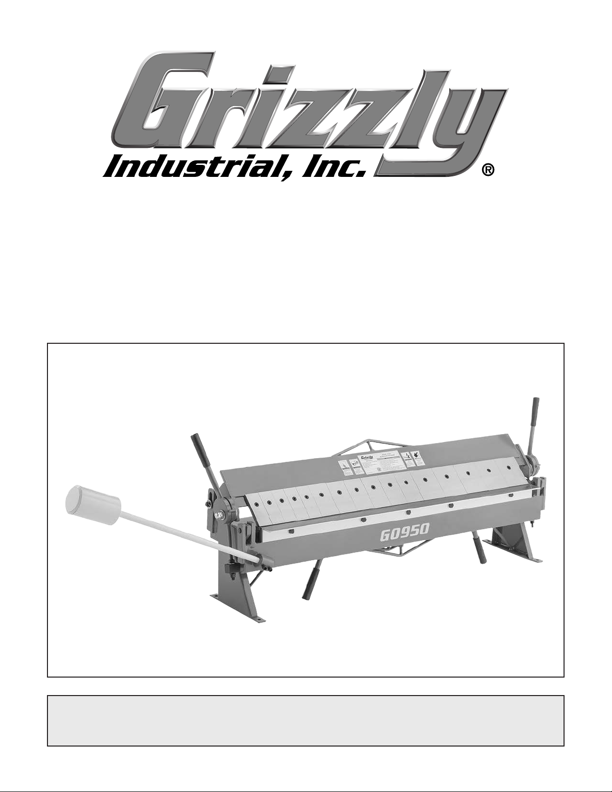
MODEL G0950
48" PAN & BOX BRAKE
OWNER'S MANUAL
(For models manufactured since 08/21)
COPYRIGHT © OCTOBER, 2021 BY GRIZZLY INDUSTRIAL, INC.
WARNING : NO PORTION OF THIS MANUAL MAY BE REPRODUCED IN ANY SHAPE
OR FORM WITHOUT THE WRITTEN APPROVAL OF GRIZZLY INDUSTRIAL, INC.
#KS22042 PRINTED IN CHINA
V1.1 0 . 21
Page 2
This manual provides critical safety instructions on the proper setup,
operation, maintenance, and service of this machine/tool. Save this
document, refer to it often, and use it to instruct other operators.
Failure to read, understand and follow the instructions in this manual
may result in fire or serious personal injury—including amputation,
electrocution, or death.
The owner of this machine/tool is solely responsible for its safe use.
This responsibility includes but is not limited to proper installation in
a safe environment, personnel training and usage authorization,
proper inspection and maintenance, manual availability and comprehension, application of safety devices, cutting/sanding/grinding tool
integrity, and the usage of personal protective equipment.
The manufacturer will not be held liable for injury or property damage
from negligence, improper training, machine modifications or misuse.
Some dust created by power sanding, sawing, grinding, drilling, and
other construction activities contains chemicals known to the State
of California to cause cancer, birth defects or other reproductive
harm. Some examples of these chemicals are:
• Lead from lead-based paints.
• Crystalline silica from bricks, cement and other masonry products.
• Arsenic and chromium from chemically-treated lumber.
Your risk from these exposures varies, depending on how often you
do this type of work. To reduce your exposure to these chemicals:
Work in a well ventilated area, and work with approved safety equipment, such as those dust masks that are specially designed to filter
out microscopic particles.
Page 3

Table of Contents
INTRODUCTION ............................................................................................................................... 2
Contact Info
Manual Accuracy
Identification
Controls & Components
Machine Data Sheet
................................................................................................................................ 2
........................................................................................................................ 2
............................................................................................................................... 3
............................................................................................................. 4
................................................................................................................... 5
SECTION 1: SAFETY
Safety Instructions for Machinery
Additional Safety for Pan & Box Brakes
SECTION 2: SETUP
Needed for Setup
Unpacking
Inventory
Cleanup
Cleaning Fingers
Site Considerations
Lifting & Placing
Bench Mounting
SECTION 3: OPERATIONS
Operation Overview.................................................................................................................. 13
Spacing Fingers
Aligning Fingers........................................................................................................................ 14
Adjusting Setback..................................................................................................................... 15
Adjusting Clamping Pressure
Basic Bending
Bending Allowance
Positioning Counterweight........................................................................................................ 18
.................................................................................................................................. 9
................................................................................................................................... 10
.................................................................................................................................... 10
....................................................................................................................... 6
............................................................................................... 6
.................................................................................... 8
......................................................................................................................... 9
....................................................................................................................... 9
...................................................................................................................... 11
.................................................................................................................. 11
....................................................................................................................... 12
....................................................................................................................... 12
........................................................................................................... 13
....................................................................................................................... 14
................................................................................................... 16
.......................................................................................................................... 17
................................................................................................................... 18
SECTION 4: ACCESSORIES
SECTION 5: MAINTENANCE......................................................................................................... 20
Schedule
Cleaning & Protecting
Lubrication
SECTION 6: SERVICE
Troubleshooting
Aligning Bending Block
SECTION 7: PARTS
Main
Labels & Cosmetics
WARRANTY & RETURNS
.................................................................................................................................. 20
................................................................................................................................ 20
................................................................................................................... 21
........................................................................................................................ 21
....................................................................................................................... 23
.......................................................................................................................................... 23
......................................................................................................... 19
.............................................................................................................. 20
............................................................................................................ 22
................................................................................................................. 24
............................................................................................................. 25
Page 4
We are proud to provide a high-quality owner’s
manual with your new machine!
We
instructions, specifications, drawings, and photographs
in this manual. Sometimes we make mistakes, but
our policy of continuous improvement also means
that
you receive is
slightly different than shown in the manual
If you find this to be the case, and the difference
between the manual and machine leaves you
confused or unsure about something
check our
website for an updated version. W
current
manuals and
on our web-
site at
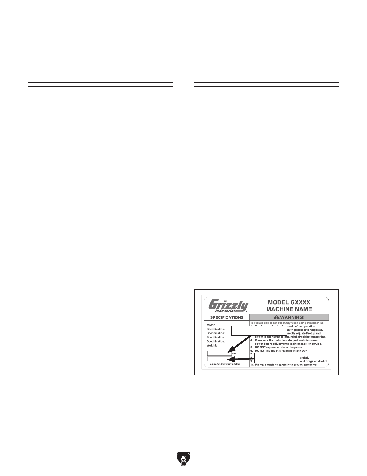
Alternatively, you can call our Technical Support
for help. Before calling, make sure you write
down the
serial number
from the machine ID label (see below). This
information is required for us to provide proper
tech support, and it helps us determine if updated
documentation is available for your machine.
We stand behind our machines! If you have questions or need help, contact us with the information
below. Before contacting, make sure you get the
serial number
from the
machine ID label. This will help us help you faster.
We want your feedback on this manual. What did
you like about it? Where could it be improved?
Please take a few minutes to give us feedback.
Email: [email protected]
INTRODUCTION
Contact Info
and manufacture date
Grizzly Technical Support
1815 W. Battlefield
Springfield, MO 65807
Phone: (570) 546-9663
Email: [email protected]
Grizzly Documentation Manager
P.O. Box 2069
Bellingham, WA 98227-2069
Manual Accuracy
made every effort to be exact with the
sometimes the machine
.
,
e post
manual updates for free
www.grizzly.com.
manufacture date and
Manufacture Date
Serial Number
-2-
Model G0950 (Mfd. Since 08/21)
Page 5
To reduce your risk of
serious injury, read this
entire manual BEFORE
Identification
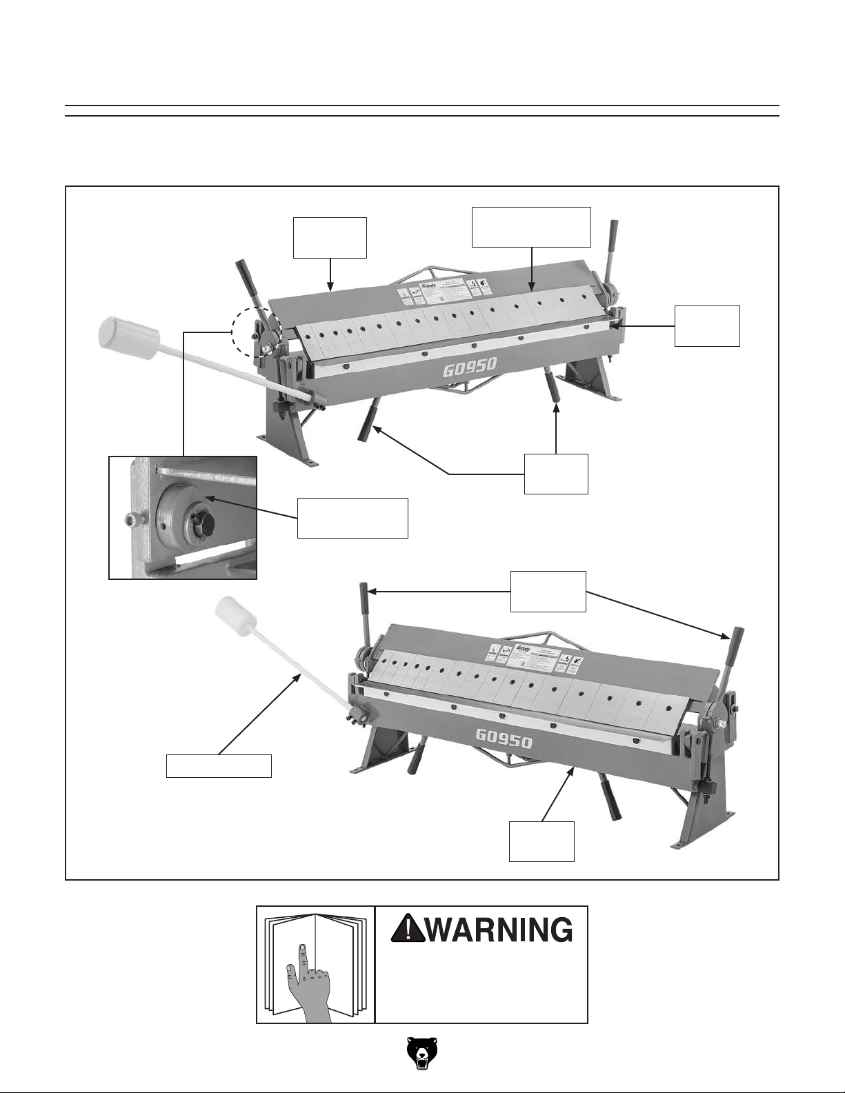
Become familiar with the names and locations of the controls and features shown below to better understand
the instructions in this manual.
Clamping
Leaf
Setback Wheel
(1 of 2)
Clamping Finger
(1 of 16)
Bending
Block
Bending
Handles
Clamping
Handles
Counterweight
Model G0950 (Mfd. Since 08/21)
Bending
Leaf
using machine.
-3-
Page 6
To reduce your risk of
serious injury, read this
entire manual BEFORE
Crushing hazard! Always
keep hands clear when
Controls &
Components
using machine.
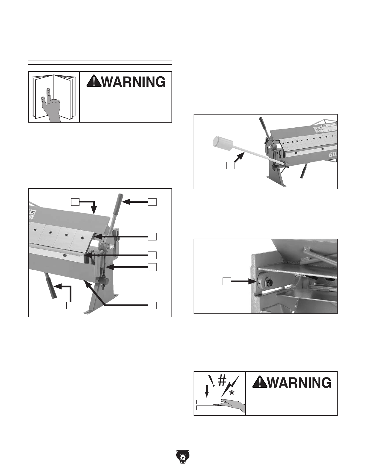
Refer to the following figures and descriptions to
become familiar with the basic controls and components of this machine. Understanding these
items and how they work will help you understand
the rest of the manual and minimize your risk of
injury when operating this machine.
A B
E.
Clamping Pressure Adjustment Rod
(1 of 2): Move up or down to set clamp-
ing pressure on workpiece according to
workpiece gauge. Lock rod in place with jam
nuts.
Bending Leaf: Swivels up to bend workpiece.
F.
Bending Handle (1 of 2): Use to raise bend-
G.
ing leaf and form bend in workpiece.
H
Figure 2. Bending leaf counterweight.
H. Counterweight: Provides leverage for bend-
ing thick workpieces. Can be adjusted or
removed.
C
D
E
FG
Figure 1. Controls and components—front.
Clamping Leaf: Holds and positions clamp-
A.
ing fingers.
Clamping Handle (1 of 2): Use to raise and
B.
lower clamping leaf.
Clamping Finger (1 of 16): Holds workpiece
C.
in place while bending block produces bend.
Fingers can be individually removed or repositioned to allow clearance for workpiece.
I
Figure 3. Controls and components—rear.
I. Setback Wheel (1 of 2): Use to adjust dis-
tance between clamping fingers and bending block. Moves clamping leaf forward and
backward.
using this machine.
Bending Block: Pivots with bending leaf to
D.
produce bend in workpiece.
-4-
Model G0950 (Mfd. Since 08/21)
Page 7

Machine Data Sheet
MACHINE DATA
SHEET
Customer Service #: (570) 546-9663 · To Order Call: (800) 523-4777 · Fax #: (800) 438-5901
MODEL G0950 48" PAN AND BOX BRAKE
Product Dimensions:
Weight.............................................................................................................................................................. 313 lbs.
Width (side-to-side) x Depth (front-to-back) x Height..................................................................... 78-1/2 x 18 x 31 in.
Footprint (Length x Width)..................................................................................................................... 52 x 12-1/2 in.
Shipping Dimensions:
Type...................................................................................................................................................... Wooden Crate
Content........................................................................................................................................................... Machine
Weight.............................................................................................................................................................. 383 lbs.
Length x Width x Height....................................................................................................................... 62 x 18 x 26 in.
Must Ship Upright................................................................................................................................................... Yes
Main Specifications:
Capacities
Maximum Width......................................................................................................................................... 48 in.
Maximum Thickness at Half Width Mild Steel..................................................................................... 16 Gauge
Maximum Thickness at Full Width Mild Steel..................................................................................... 18 Gauge
Aluminum............................................................................................................................................ 11 Gauge
Stainless Steel.................................................................................................................................... 20 Gauge
Brake Range................................................................................................................................... 0 - 135 deg.
Minimum Reverse Bend......................................................................................................................... 7/16 in.
Maximum Height of Pan/Box Brake Sides............................................................................................. 2-1/2 in.
Number of Fingers.......................................................................................................................................... 16
Width of Fingers.................................................................................................................................. 2, 3, 4 in.
Construction
Base........................................................................................................................................................... Steel
Bending Leaf.............................................................................................................................................. Steel
Clamping Leaf............................................................................................................................................ Steel
Fingers............................................................................................... Precision-Ground Steel, Hardened Edge
Other Specifications:
Country of Origin ................................................................................................................................................ China
Warranty ........................................................................................................................................................... 1 Year
Approximate Assembly & Setup Time ........................................................................................................ 15 Minutes
Serial Number Location .................................................................................................................................. ID Label
Features:
Bending Leaf Counterweighted for Leverage
Precision-Ground Steel Fingers with Hardened Edges
Sixteen Adjustable/Removable Fingers
Model G0950 (Mfd. Since 08/21)
-5-
Page 8
SECTION 1: SAFETY
For Your Own Safety, Read Instruction
Manual Before Operating This Machine
The purpose of safety symbols is to attract your attention to possible hazardous conditions.
This manual uses a series of symbols and signal words intended to convey the level of importance of the safety messages. The progression of symbols is described below. Remember that
safety messages by themselves do not eliminate danger and are not a substitute for proper
accident prevention measures. Always use common sense and good judgment.
Indicates an imminently hazardous situation which, if not avoided,
WILL result in death or serious injury.
Indicates a potentially hazardous situation which, if not avoided,
COULD result in death or serious injury.
Indicates a potentially hazardous situation which, if not avoided,
MAY result in minor or moderate injury. It may also be used to alert
against unsafe practices.
Alerts the user to useful information about proper operation of the
NOTICE
machine to avoid machine damage.
Safety Instructions for Machinery
OWNER’S MANUAL. Read and understand this
owner’s manual BEFORE using machine.
TRAINED OPERATORS ONLY. Untrained operators have a higher risk of being hurt or killed.
Only allow trained/supervised people to use this
machine. When machine is not being used, disconnect power, remove switch keys, or lock-out
machine to prevent unauthorized use—especially
around children. Make your workshop kid proof!
DANGEROUS ENVIRONMENTS. Do not use
machinery in areas that are wet, cluttered, or have
poor lighting. Operating machinery in these areas
greatly increases the risk of accidents and injury.
MENTAL ALERTNESS REQUIRED. Full mental
alertness is required for safe operation of machinery. Never operate under the influence of drugs or
alcohol, when tired, or when distracted.
ELECTRICAL EQUIPMENT INJURY RISKS.
You can be shocked, burned, or killed by touching
live electrical components or improperly grounded
machinery. To reduce this risk, only allow qualified
service personnel to do electrical installation or
repair work, and always disconnect power before
accessing or exposing electrical equipment.
DISCONNECT POWER FIRST.
nect machine from power supply BEFORE making adjustments, changing tooling, or servicing
machine. This prevents an injury risk from unintended startup or contact with live electrical components.
EYE PROTECTION. Always wear ANSI-approved
safety glasses or a face shield when operating or
observing machinery to reduce the risk of eye
injury or blindness from flying particles. Everyday
eyeglasses are NOT approved safety glasses.
Always discon-
-6-
Model G0950 (Mfd. Since 08/21)
Page 9
WEARING PROPER APPAREL. Do not wear
clothing, apparel or jewelry that can become
entangled in moving parts. Always tie back or
cover long hair. Wear non-slip footwear to reduce
risk of slipping and losing control or accidentally
contacting cutting tool or moving parts.
HAZARDOUS DUST. Dust created by machinery
operations may cause cancer, birth defects, or
long-term respiratory damage. Be aware of dust
hazards associated with each workpiece material. Always wear a NIOSH-approved respirator to
reduce your risk.
HEARING PROTECTION. Always wear hearing protection when operating or observing loud
machinery. Extended exposure to this noise
without hearing protection can cause permanent
hearing loss.
REMOVE ADJUSTING TOOLS. Tools left on
machinery can become dangerous projectiles
upon startup. Never leave chuck keys, wrenches,
or any other tools on machine. Always verify
removal before starting!
USE CORRECT TOOL FOR THE JOB. Only use
this tool for its intended purpose—do not force
it or an attachment to do a job for which it was
not designed. Never make unapproved modifications—modifying tool or using it differently than
intended may result in malfunction or mechanical
failure that can lead to personal injury or death!
AWKWARD POSITIONS. Keep proper footing
and balance at all times when operating machine.
Do not overreach! Avoid awkward hand positions
that make workpiece control difficult or increase
the risk of accidental injury.
CHILDREN & BYSTANDERS. Keep children and
bystanders at a safe distance from the work area.
Stop using machine if they become a distraction.
GUARDS & COVERS. Guards and covers reduce
accidental contact with moving parts or flying
debris. Make sure they are properly installed,
undamaged, and working correctly BEFORE
operating machine.
FORCING MACHINERY. Do not force machine.
It will do the job safer and better at the rate for
which it was designed.
NEVER STAND ON MACHINE. Serious injury
may occur if machine is tipped or if the cutting
tool is unintentionally contacted.
STABLE MACHINE. Unexpected movement during operation greatly increases risk of injury or
loss of control. Before starting, verify machine is
stable and mobile base (if used) is locked.
USE RECOMMENDED ACCESSORIES. Consult
this owner’s manual or the manufacturer for recommended accessories. Using improper accessories will increase the risk of serious injury.
UNATTENDED OPERATION. To reduce the
risk of accidental injury, turn machine OFF and
ensure all moving parts completely stop before
walking away. Never leave machine running
while unattended.
MAINTAIN WITH CARE. Follow all maintenance
instructions and lubrication schedules to keep
machine in good working condition. A machine
that is improperly maintained could malfunction,
leading to serious personal injury or death.
DAMAGED PARTS. Regularly inspect machine
for damaged, loose, or mis-adjusted parts—or
any condition that could affect safe operation.
Immediately repair/replace BEFORE operating
machine. For your own safety, DO NOT operate
machine with damaged parts!
MAINTAIN POWER CORDS. When disconnecting cord-connected machines from power, grab
and pull the plug—NOT the cord. Pulling the cord
may damage the wires inside. Do not handle
cord/plug with wet hands. Avoid cord damage by
keeping it away from heated surfaces, high traffic
areas, harsh chemicals, and wet/damp locations.
EXPERIENCING DIFFICULTIES. If at any time
you experience difficulties performing the intended operation, stop using the machine! Contact our
Technical Support at (570) 546-9663.
Model G0950 (Mfd. Since 08/21)
-7-
Page 10
Additional Safety for Pan & Box Brakes
Hands/fingers can be crushed or severely pinched if caught between clamping fingers and
bending blocks during operation. Severe cuts can occur to hands/fingers when contacting
sharp workpiece edges. To minimize risk of injury, anyone operating this machine MUST
completely heed the hazards and warnings below.
CRUSHING & AMPUTATION INJURIES. The
brake can quickly crush or amputate fingers,
hands, or body parts. Never place fingers, hands,
or body parts between or near the clamping fingers and bending blocks during operation.
SECURING BRAKE. Before using, secure the
brake to the workbench so it can support the
weight and dynamic forces involved in bending
sheet metal. Otherwise, the brake may unexpectedly move or tip during operation, causing serious
injury or property damage.
TOOLS IN POOR CONDITION. Using this tool
with loose hardware or damaged components
could result in sudden, unexpected movements
during use. Inspect the brake for cracked components, damaged linkage, levers, or loose fasteners. Correct any problems before use.
LEAVING UNATTENDED. To reduce the risk of
crushing or amputation injuries with children or visitors, lower the clamping leaf when not in use.
METAL EDGES. Sharp edges on sheet metal can
produce severe cuts. Always wear leather gloves
and chamfer/de-burr sharp sheet metal edges
before bending the workpiece with this machine.
COMFORTABLE BODY POSITION. The required
body motion to operate the brake can result in
operator injury over time if proper ergonomics are
not used during operation.
HEATING METAL. Heating the workpiece with a
torch or welding it while clamped in the brake may
weaken the fingers, blocks, and frame. Do not use
a torch, welder, or other similar heating tool near
the brake.
CAPACITY. Exceeding the capacity of the brake
may result in sudden breakage that ejects dangerous metal debris at the operator or bystanders, or
causes machine damage. Only use sheet metal
that is within the rated capacity of this brake (refer
to the Machine Data Sheet).
Like all machinery there is potential danger
when operating this machine. Accidents
are frequently caused by lack of familiarity
or failure to pay attention. Use this machine
with respect and caution to decrease the
risk of operator injury. If normal safety precautions are overlooked or ignored, serious personal injury may occur.
-8-
No list of safety guidelines can be complete. Every shop environment is different.
Always consider safety first, as it applies
to your individual working conditions. Use
this and other machinery with caution and
respect. Failure to do so could result in
serious personal injury, damage to equipment, or poor work results.
Model G0950 (Mfd. Since 08/21)
Page 11
This machine was carefully packaged for safe
transport. When unpacking, separate all enclosed
items from packaging materials and inspect them
for shipping damage.
,
please
IMPORTANT:
you are completely satisfied with the machine and
have resolved any issues between Grizzly or the
shipping agent. You MUST have the original pack-
aging to file a freight claim. It is also extremely
helpful if you need to return your machine later.
The following items are needed, but not included,
for the setup/assembly of this machine.
SECTION 2: SETUP
This machine presents
serious injury hazards
to untrained users. Read
through this entire manual to become familiar with
the controls and operations before starting the
machine!
Wear safety glasses and leather work gloves
during the entire setup process!
Needed for Setup
Description Qty
• Forklift ......................................................... 1
• Lifting Straps (rated for 500 lbs.) ................ 2
• Additional People ....................... As Needed
• Safety Glasses (each person) ............. 1 Pair
• Leather Work Gloves (each person) ....1 Pair
• Solvent/Cleaner (Page 10) ......... As Needed
• Clean Shop Rags ....................... As Needed
• Wood 2x4 (12" Length) ............... As Needed
• Mounting Hardware (Page 12) ... As Needed
HEAVY LIF T!
Straining or crushing injury
may occur from improperly
lifting machine or some of
its parts. To reduce this risk,
get help from other people
and use a forklift (or other
lifting equipment) rated for
weight of this machine.
Unpacking
If items are damaged
call us immediately at (570) 546-9663.
Save all packaging materials until
Model G0950 (Mfd. Since 08/21)
-9-
Page 12
The unpainted surfaces of your machine are
coated with a heavy-duty rust preventative that
prevents corrosion during shipment and storage.
This rust preventative works extremely well, but it
will take a little time to clean.
Be patient and do a thorough job cleaning your
machine. The time you spend doing this now will
give you a better appreciation for the proper care
of your machine's unpainted surfaces.
There are many ways to remove this rust preventative, but the following steps work well in a wide
variety of situations. Always follow the manufacturer’s instructions with any cleaning product you
use and make sure you work in a well-ventilated
area to minimize exposure to toxic fumes.
Before cleaning, gather the following:
• Disposable rags
• Cleaner/degreaser (WD•40 works well)
• Safety glasses & disposable gloves
• Plastic paint scraper (optional)
Basic steps for removing rust preventative:
1.
2. Coat the rust preventative with a liberal
amount of cleaner/degreaser, then let it soak
3.
off easily. If you have a plastic paint scraper,
scrape off as much as you can first, then wipe
4.
then coat all unpainted surfaces with a quality
The following is a list of items shipped with your
machine. Before beginning setup, lay these items
out and inventory them.
If any non-proprietary parts are missing (e.g. a
nut or a washer), we will gladly replace them; or
for the sake of expediency, replacements can be
obtained at your local hardware store.
Cleanup
Inventory
If you cannot find an item on this list, carefully check around/inside the machine and
packaging materials. Often, these items get
lost in packaging materials while unpacking or they are pre-installed at the factory.
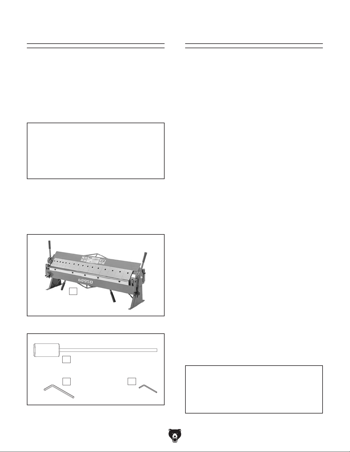
Inventory (Figures 4–5) Qty
A. Pan & Box Brake ........................................ 1
Counterweight ............................................ 1
B.
Hex Wrench 8mm ....................................... 1
C.
Hex Wrench 6mm ....................................... 1
D.
NOTICE
Cleanup
Put on safety glasses.
-10 -
A
Figure 4. Pan & box brake.
B
C
Figure 5. Loose inventory.
D
for 5–10 minutes.
Wipe off the surfaces. If your cleaner/degreas-
er is effective, the rust preventative will wipe
off the rest with the rag.
Repeat Steps 2–3 as necessary until clean,
metal protectant to prevent rust.
NOTICE
Avoid harsh solvents like acetone or brake
parts cleaner that may damage painted surfaces. Always test on a small, inconspicuous location first.
Model G0950 (Mfd. Since 08/21)
Page 13
Refer to the Machine Data Sheet for the weight
and footprint specifications of your machine.
Some workbenches may require additional reinforcement to support the weight of the machine
and workpiece materials.
Consider anticipated workpiece sizes and additional space needed for auxiliary stands, work
tables, or other machinery when establishing a
location for this machine in the shop. Below is
the minimum amount of space needed for the
Cleaning Fingers
Site Considerations
Although rust preventative was applied only to
the visible surfaces of the clamping fingers (see
Figure 6), some may have worked in between and
underneath them. We recommend you remove all
the clamping fingers and thoroughly clean them.
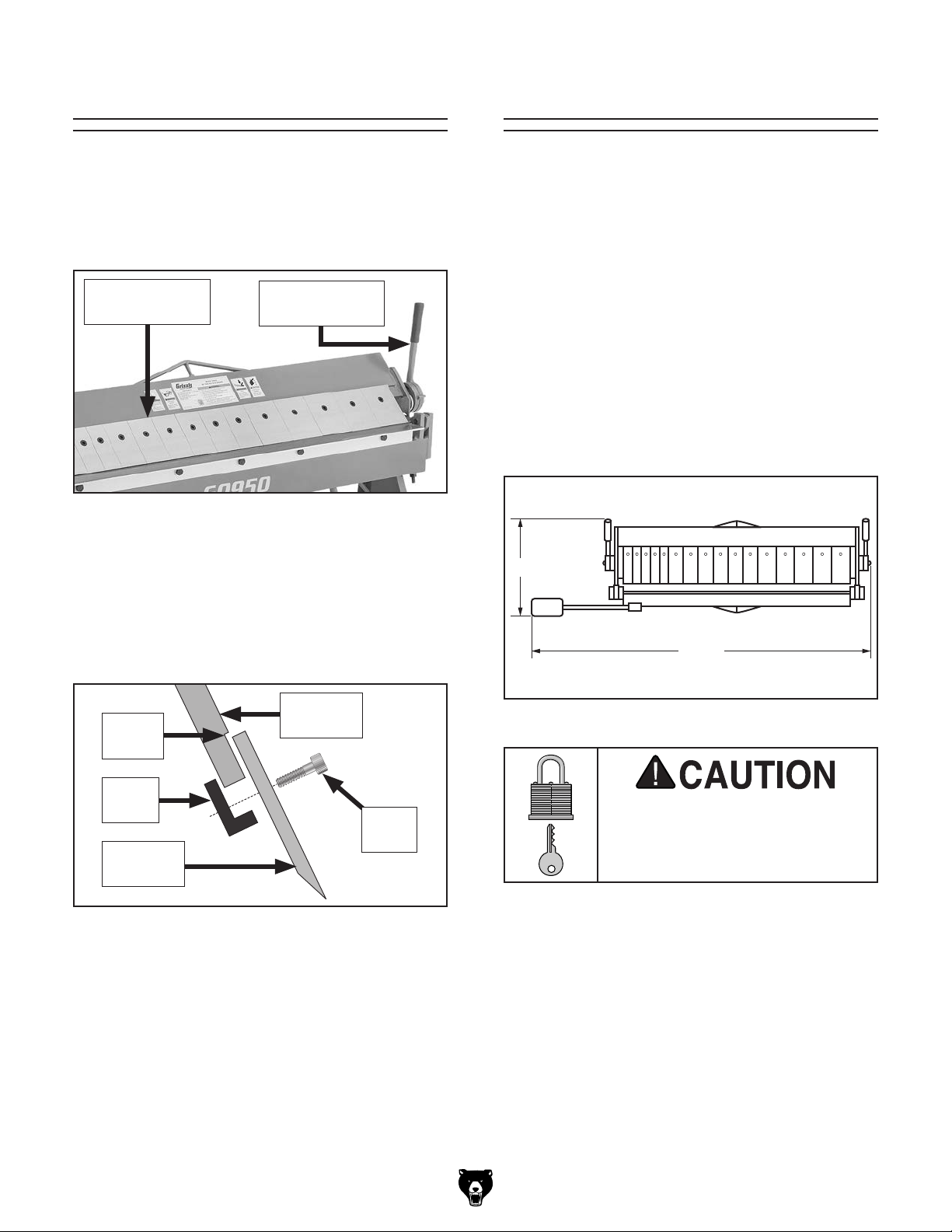
Clamping
Finger (1 of 16)
Figure 6. Location of clamping handle and
fingers.
To remove the clamping fingers, move the clamping handles (see
machine to raise the clamping leaf, then loosen
the cap screws and remove the clamping fingers
and toe clamps (see
Figure 6) toward the back of the
Figure 7).
Clamping
Handle (1 of 2)
Workbench Load
Placement Location
18"
781⁄2"
Clamping
Finger
Guide
Toe
Clamp
Clamping
Finger
Figure 7. Clamping finger components.
After all the fingers have been cleaned, coat them
liberally with a metal protectant (see
and clean the finger guide on the clamping leaf.
Place the fingers along the guide on the clamping leaf, align the toe clamps to catch the bottom
of the clamping leaf, and tighten the cap screws
enough so the fingers will not fall off. When done,
make sure the fingers are properly aligned (refer
to Aligning Fingers on
Model G0950 (Mfd. Since 08/21)
Page 14).
Leaf
Screw
Cap
Page 19),
Figure 8. Minimum working clearances.
Children or untrained people
may be seriously injured by
this machine. Only install in an
access restricted location.
-11-
Page 14
Another option is a "direct mount" (see example
below) where the machine is secured directly to
the workbench with lag screws and washers.
The base of this machine has mounting holes
that allow it to be fastened to a workbench or
other mounting surface to prevent it from moving
during operation and causing accidental injury or
damage.
The strongest mounting option is a "Through
Mount" (see example below) where holes are
drilled all the way through the workbench—and
hex bolts, washers, and hex nuts are used to
secure the machine in place.
Lifting & Placing
HEAVY LIF T!
Straining or crushing injury
may occur from improperly
lifting machine or some of
its parts. To reduce this risk,
get help from other people
and use a forklift (or other
lifting equipment) rated for
weight of this machine.
To lift and place machine on workbench:
Using a forklift, move crate to machine work
1.
site location.
Remove crate top and sides, components
2.
inside crate, and blocks around machine base.
Bench Mounting
Number of Mounting Holes ............................ 4
Diameter of Mounting Hardware Needed
Hex
Bolt
..3⁄8"
Remove fasteners securing machine to base.
3.
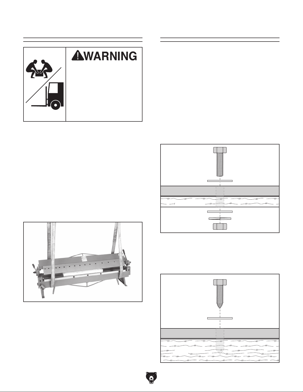
Secure clamping leaf by inserting a wood 2x4
4.
between clamping leaf and bending block
(see Figure 9).
Figure 9. Example of pan & box brake supported
by lifting straps and 2x4 to secure clamping leaf.
Use forklift to raise machine, then place onto
5.
workbench.
Flat Washer
Machine Base
Workbench
Flat Washer
Lock Washer
Hex Nut
Figure 10. "Through Mount" setup.
Lag Screw
Flat Washer
Machine Base
Fasten machine to workbench following
6.
instructions in Bench Mounting.
-12-
Workbench
Figure 11. "Direct Mount" setup.
Model G0950 (Mfd. Since 08/21)
Page 15
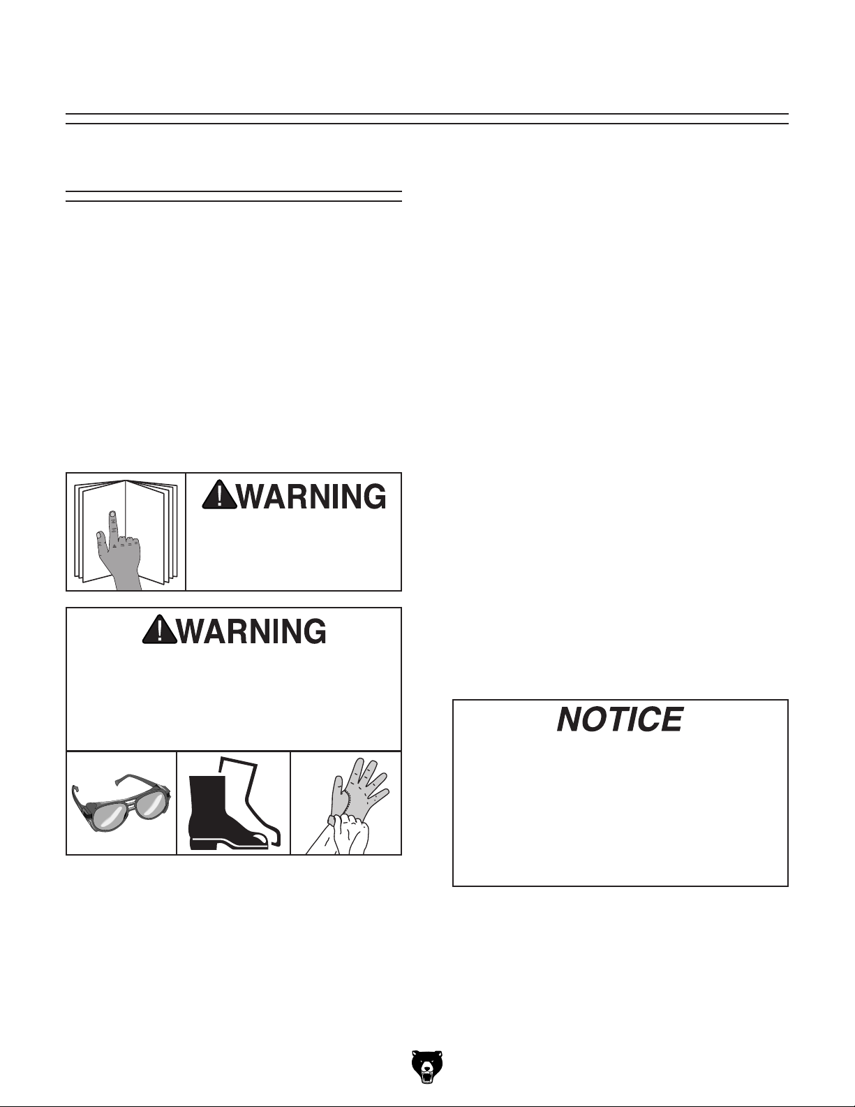
To reduce your risk of
serious injury, read this
entire manual BEFORE
SECTION 3: OPERATIONS
The purpose of this overview is to provide the novice machine operator with a basic understanding
of how the machine is used during operation, so
the
discussed later
in this manual
Due to the generic nature of this overview, it is
not intended to be an instructional guide. To learn
more about specific operations, read this entire
manual,
training from experienced
machine operators
outside of this manual by reading "how-to" books,
trade magazines, or websites.
Operation Overview
machine controls/components
are easier to understand.
seek additional
, and do additional research
To complete a typical operation, the operator
does the following:
Examines workpiece to make sure it is suit-
1.
able for bending.
If required for the operation, adjusts clamping
2.
finger spacing.
Positions counterweight depending on
3.
workpiece thickness.
Adjusts clamping pressure for workpiece
4.
thickness.
Correctly adjusts setback.
5.
6. Puts on safety glasses, leather boots, and
leather gloves.
using machine.
Bodily injury could result from using this
machine. Always wear safety glasses,
leather work boots, and heavy duty leather
work gloves when operating this machine
or whenever handling sheet metal.
Properly positions workpiece underneath
7.
clamping fingers and lowers clamping leaf to
secure workpiece.
With body square to brake and using both
8.
hands, raises bending leaf to form correct
bend angle.
Lowers bending leaf and removes workpiece.
9.
If you are not experienced with this type
of machine, WE STRONGLY RECOMMEND
that you seek additional training outside of
this manual. Read books/magazines or get
formal training before beginning any projects. Regardless of the content in this section, Grizzly Industrial will not be held liable
for accidents caused by lack of training.
Model G0950 (Mfd. Since 08/21)
-13-
Page 16
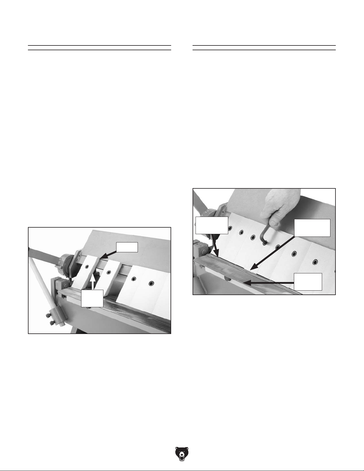
aligning fingers
Spacing Fingers
The clamping fingers can be spaced apart for
clearance when making pans or boxes. This
requires removing one or more of the fingers, so
that you can space the others to match the inside
width of your pan or box.
Tool Needed: Qty
Hex Wrench 8mm .............................................. 1
To space clamping fingers:
Loosen cap screw on each finger you need to
1.
remove.
Remove fingers and toe clamps from clamp-
2.
ing leaf, as shown in
aside.
Note: You may need to mix and match fin-
ger widths or space fingers appropriately to
match the inside width of your pan or box.
Figure 12, and set them
Aligning Fingers
To help ensure the bend is even along its length,
the clamping fingers must be parallel with the
clamping surface and bending block.
Tool Needed: Qty
Hex Wrench 8mm .............................................. 1
To align clamping fingers:
Lower clamping leaf until clamping fingers
1.
just touch clamping surface (see Figure
Look closely along bottom edge of each fin-
2.
ger to determine if any are out of alignment
with clamping surface and bending block, as
shown in Figure
Clamping
Surface
13.
Misaligned
Finger
13).
Finger
Toe
Clamp
Figure 12. Example of finger spacing.
Align remaining fingers and tighten cap
3.
screws.
Bending
Block
Figure 13. Example of a misaligned clamping
finger.
3. Loosen cap screw on misaligned finger just
enough to move it up or down.
Align finger parallel with clamping surface
4.
and bending block, and then tighten cap
screw.
-14-
Model G0950 (Mfd. Since 08/21)
Page 17
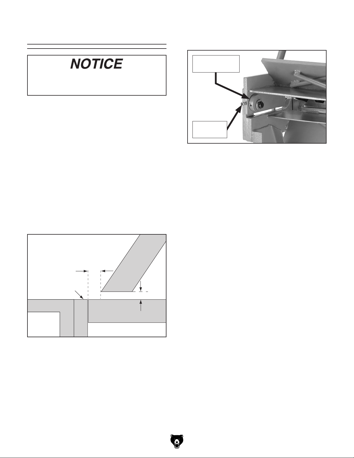
adjusting setback
Adjusting Setback
You must include the thickness of folded
edges or joints when determining the proper setback, or the brake may be damaged.
Before you begin any bending operation, consider
the differences of sheet metal gauges when trying to achieve either sharp or rounded bends, and
allow for the differences by adjusting the setback.
3. Loosen cap screws securing setback wheels
(see Figure
15).
Setback Wheel
(1 of 2)
Cap Screw
(1 of 2)
Setback is the distance from the forward edge
of the fingers to the edge of the bending leaf,
as shown in Figure
14. The setback distance is
determined by the gauge of the workpiece material and the desired radius of the bend.
1
Setback is normally adjusted 1
⁄2 times the thickness of 22 gauge and thinner workpieces, and
two times the thickness of workpieces thicker than
22 gauge. G0950 material gauge capacities are
listed on the Machine Data Sheet on Page
5.)
Setback
1
1
/
x A
2
Bending
Leaf
Distance
Finger
A
Clamping
Bending
Block
Surface
Edge View
Figure 15. Location of setback wheel and cap
screw.
Rotate both setback wheels until desired set-
4.
back distance is achieved.
Note: Setback wheels are eccentric. Turning
them one full turn will bring clamping leaf
back to its original position.
Tip: If you find it hard to turn setback wheels
with your fingers, insert a hex wrench into the
holes on edges of wheels to gain leverage.
. Lower clamping fingers onto clamping sur-
5
face and check setback distance.
. If necessary, repeat Steps 2–4 until desired
6
setback is achieved.
. Check finger alignment (refer to Aligning
7
Fingers on
Page 14).
Figure 14. Determining setback distance for
workpieces 22 gauge and thinner.
Tool Needed: Qty
Hex Wrench 6mm .............................................. 1
To adjust setback:
1. Determine setback required for bend.
2. Raise clamping fingers about 1⁄2" off of clamp-
ing surface (see Figure 14, A).
Model G0950 (Mfd. Since 08/21)
-15-
Page 18
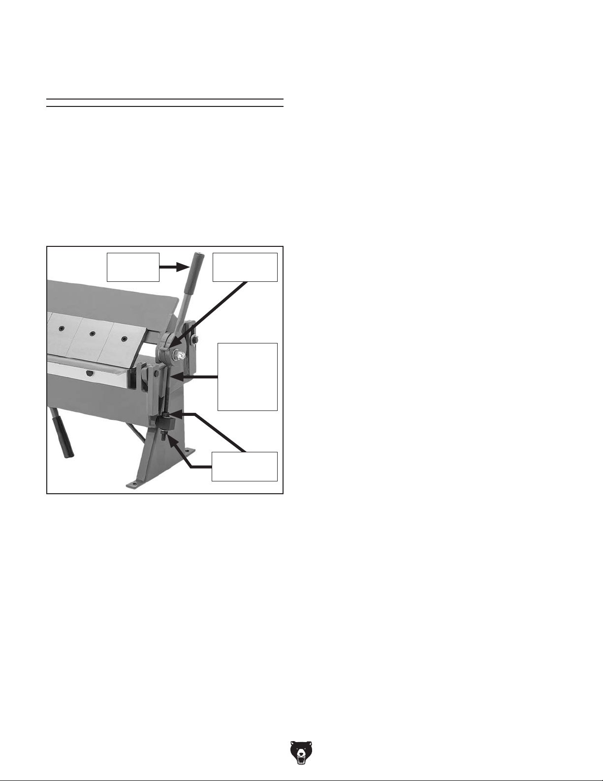
adjusting clamping pressure
Adjusting Clamping
Tool Needed: Qty
Open-End Wrench 19mm .................................. 1
Pressure
Clamping pressure must be properly adjusted for
different workpiece thicknesses. The ideal pressure will have medium resistance at the clamping
handles, and will lock the workpiece into position
easily—much like a pair of Vice-Grips
is adjusted by rotating the adjustment nuts on
the clamping pressure adjustment rods (see
Figure 16). These are located on both ends of the
pan and box brake.
Clamping
Handle
®
. Pressure
Clamping
Handle Stop
Clamping
Pressure
Adjustment
Rod
(1 of 2)
To adjust clamping pressure:
Lower clamping leaf so clamping fingers just
1.
touch workpiece.
Tip: It is best if the workpiece used in this
procedure is same width as pan and box
brake. If not, place two pieces of metal of
same thickness as workpiece on each end of
brake.
— If clamping handles are at 10 o'clock
(viewed from right end of brake) and 2
o'clock (viewed from left end of brake)
position, then clamping pressure is suitable for workpiece. Proceed to
— If clamping handles are not at 10 o'clock
(viewed from right end of brake) and 2
o'clock (viewed from left end of brake)
position, then clamping pressure is not
suitable for workpiece. Proceed to
2. Loosen adjustment nuts (see Figure 16)
and turn both sets up or down until clamping
handles are in 10 and 2 o'clock position when
clamping fingers just touch workpiece.
Step 4.
Step 2.
Adjustment
Nuts (2 of 4)
Figure 16. Locations of clamping components.
3. Tighten adjustment nuts to secure
position.
4. Make sure clamping pressure is even on both
ends of brake by raising one end and testing clamping action of other end. Clamping
action should be same on both ends.
If necessary, repeat Steps 1–4 until proper
5.
clamping pressure is achieved.
Note: Proper clamping pressure is achieved
when the clamping handle "snaps" (or
locks) into position against handle stop (see
Figure
16).
-16 -
Model G0950 (Mfd. Since 08/21)
Page 19
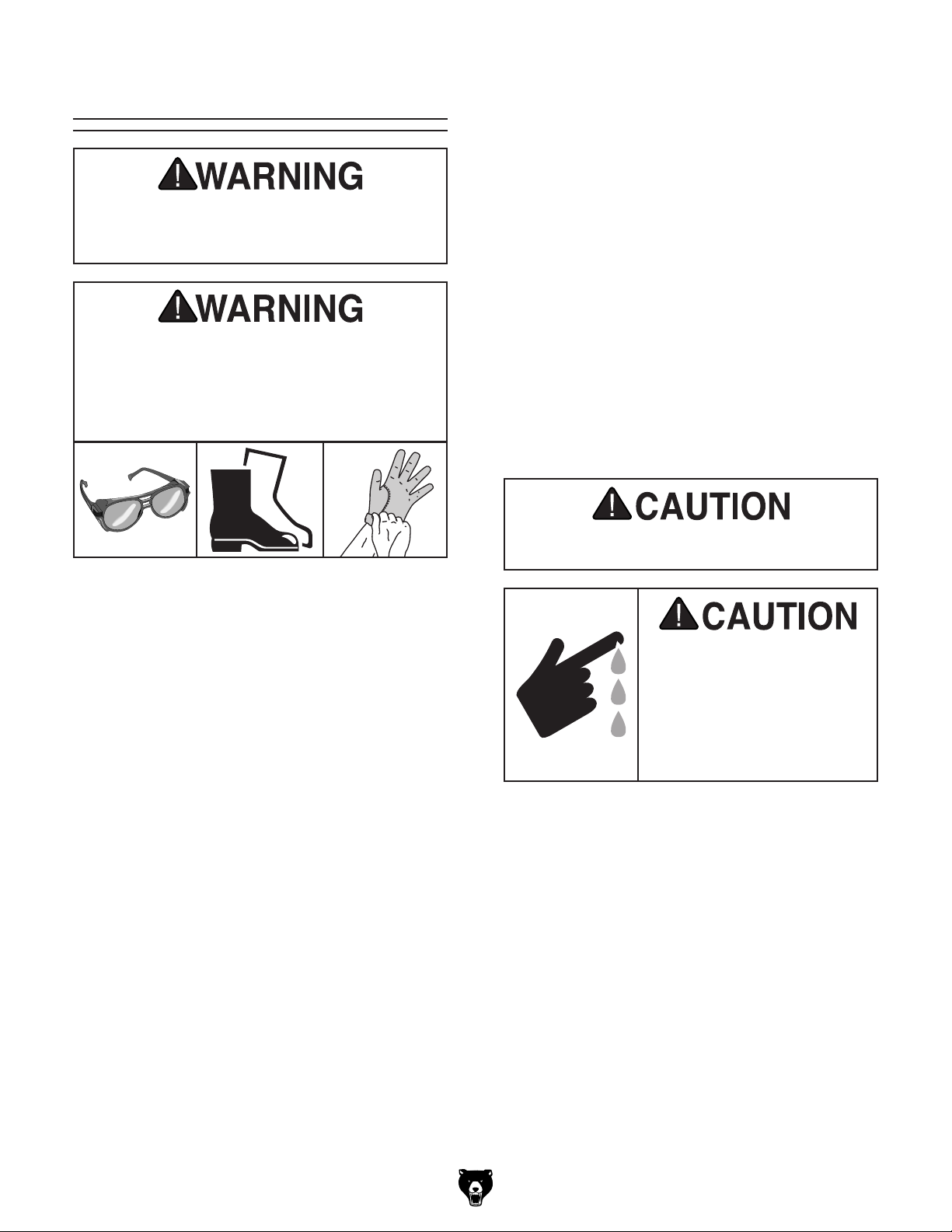
Basic Bending
Do not operate machine unless it has been
securely mounted to a workbench, or it
could tip over on you, causing severe injury!
Bodily injury could result from using this
machine. Always wear safety glasses,
leather work boots, and heavy duty leather
work gloves when operating this machine
or whenever handling sheet metal.
2. Raise clamping leaf.
Insert workpiece between clamping fingers
3.
and clamping surface.
4. Align bend mark(s) on workpiece with fingers, then clamp it in place using clamping
handles.
Note: If clamping handles do not lock, the
clamping pressure may need to be adjusted
(refer to Adjusting Clamping Pressure on
16).
Page
With body square to brake and using both
5.
hands, lift bending leaf until workpiece reaches desired bend angle.
Raise clamping leaf and remove workpiece.
6.
All bending operations require the clamping fingers to be parallel with the edge of the clamping
surface and bending block, and the setback and
clamping pressure must be correctly adjusted for
the thickness of the workpiece.
To perform basic bending operations:
1. Determine setback required for bend and
adjust machine if needed (refer to Adjusting
Setback on
Page 15).
Hold onto the workpiece so it does not drop
and hit you when it is released!
Sharp edges of sheet metal
can easily cut fingers,
hands, or other body parts.
Always wear leather gloves
when handling sheet metal,
and always chamfer and
deburr the edges.
Model G0950 (Mfd. Since 08/21)
-17-
Page 20
Bending Allowance
When a bend is made in sheet metal, the inside
surface of the bend compresses and the outside
surface stretches. To bend metal objects accurately, you need to consider the length of each
bend, especially when more than one bend is
required. This is called bend allowance.
As a rule of thumb, subtract the bend allowance
from the sum of the workpiece outside dimensions to obtain the overall length and width of the
blank needed to make a particular part.
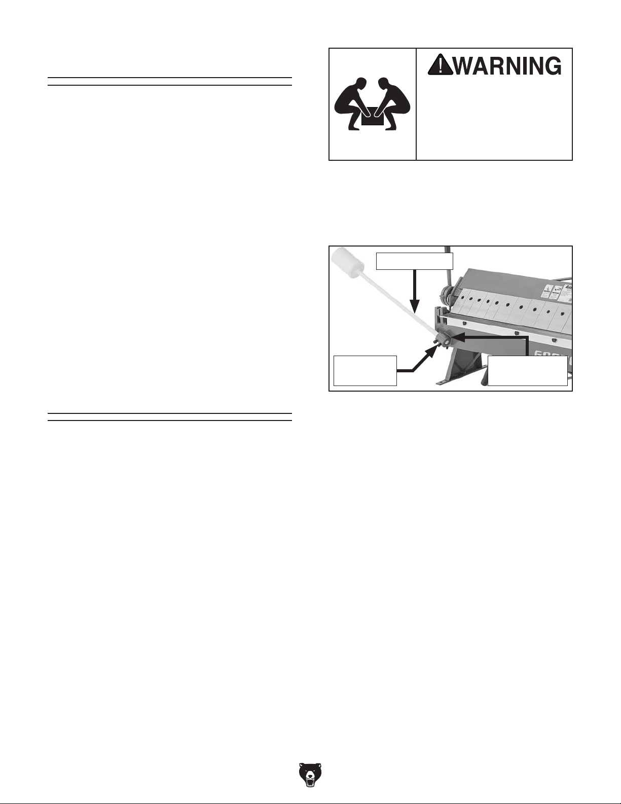
Lifting heavy machinery or
parts without proper assistance or equipment may
result in strains, back injuries, crushing injuries, or
property damage.
To position counterweight:
Loosen (2) cap screws on bending leaf coun-
1.
terweight collar (see
Figure 17).
Exact allowances can only be obtained by trial
and error due to differences in sheet metal hardness, whether the bend is with or across the
grain, and the bend radius. Use metalworking
handbooks or the internet to find bend allowances
accurate enough for average use.
Positioning
Counterweight
The counterweight helps to provide additional
leverage when bending thick workpieces, and can
be adjusted to vary the weight being applied by
the bending leaf.
The gauge of the workpiece determines where
the counterweight should be placed. For example,
the counterweight would be positioned low in the
collar for bending 20-gauge steel, and high for
bending 12-gauge steel.
Items Needed: Qty
Additional Person .............................................. 1
Hex Wrench 8mm
.............................................. 1
Counterweight
Cap Screw
(1 of 2)
Figure 17. Location of bending leaf
counterweight components.
2. Have an additional person insert counterweight into counterweight collar, then tighten
(2) cap screws to secure.
— For maximum weight leverage, posi-
tion narrow end of counterweight flush
with bottom of counterweight collar (see
Figure 17).
— For less weight leverage, extend narrow
end of counterweight beyond bottom of
counterweight collar until desired weight is
achieved.
Counterweight
Collar
-18-
Model G0950 (Mfd. Since 08/21)
Page 21
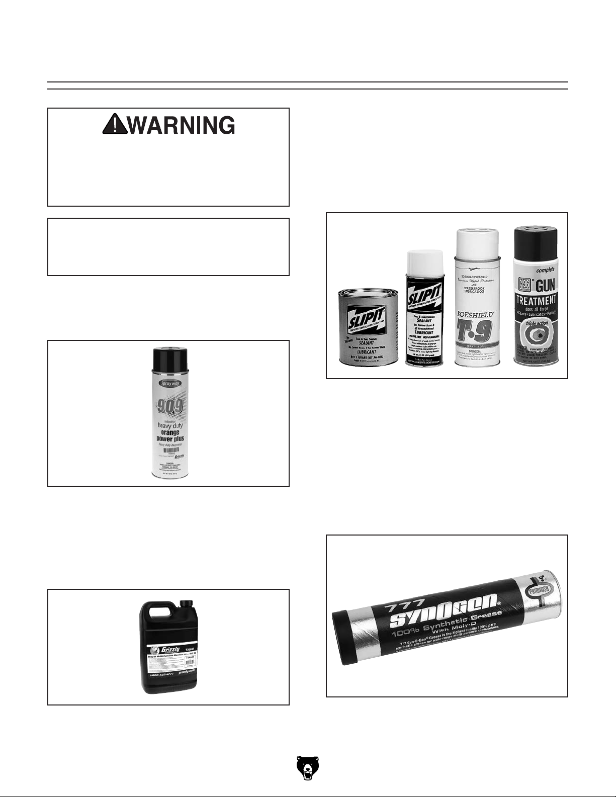
Recommended Metal Protectants
G55
G5563—SLIPIT
G2870—Boeshield
G2871—Boeshield
H3788—G96
H3789—G96
Installing unapproved accessories may
order online at www.grizzly.com or call 1-800-523-4777
recommended metal protectants
SECTION 4: ACCESSORIES
cause machine to malfunction, resulting in
serious personal injury or machine damage.
To reduce this risk, only install accessories
recommended for this machine by Grizzly.
NOTICE
Refer to our website or latest catalog for
additional recommended accessories.
T23692—Orange Power Degreaser
A great product for removing the rust-preventative
grease from your machine during clean up.
62—SLIPIT® 1 Qt. Gel
Figure 20. Recommended products for protecting
unpainted cast iron/steel parts on machinery.
®
12 Oz. Spray
®
T-9 4 Oz. Spray
®
®
Gun Treatment 12 Oz. Spray
®
Gun Treatment 4.5 Oz. Spray
T-9 12 Oz. Spray
Figure 18. T23692 Orange Power Degreaser.
T26685—Moly-D Machine Oil-ISO 32
Moly-D oils are some of the best we've found for
maintaining the critical components of machinery
because they tend to resist run-off and maintain
their lubricity under a variety of conditions.
Figure 19. Recommended product for machine
lubrication.
T26419—Syn-O-Gen Synthetic Grease
Formulated with 100% pure synthesized hydrocarbon base stocks that are compounded with special thickeners and additives to make Syn-O-Gen
non-melt, tacky, and water resistant. Extremely
low pour point, extremely high temperature oxidation, and thermal stability produce a grease that is
unmatched in performance.
Figure 21. T26419 Syn-O-Gen Synthetic
Grease.
Model G0950 (Mfd. Since 08/21)
-19 -
Page 22
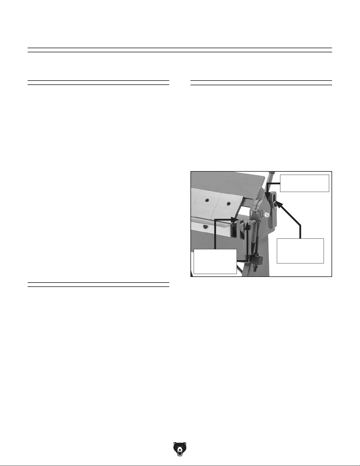
SECTION 5: MAINTENANCE
Schedule
For optimum performance from this machine, this
maintenance schedule must be strictly followed.
Ongoing
To minimize your risk of injury and maintain proper
machine operation, stop operations immediately if
you ever observe any of the items below, and fix
the problem before continuing:
• Loose mounting bolts.
• Worn or damaged clamping fingers.
Any other unsafe condition.
•
Daily Maintenance
• Lubricate clamping leaf pivots.
• Lubricate bending leaf pivots.
Weekly Maintenance
• Lubricate clamping leaf guide pin slots.
Lubrication
Clamping Leaf Pivots
Oil Type .... Grizzly T26685 or ISO 32 Equivalent
Oil Amount
Lubrication Frequency
Use an oil can to add lubricant to the hole shown
Figure 22 (one on each side of the brake), then
in
raise and lower the clamping leaf several times to
distribute the lubricant.
...........................................1–2 Drops
.........Daily, or As Needed
Clamping Leaf
Oil Hole (1 of 2)
Cleaning &
Protecting
Use a brush to clear away any metal debris and
dust from the clamping fingers, clamping base,
and bending blocks.
Use a shop rag to carefully apply a thin coat of
quality metal protectant (see
from Grizzly) to all exposed unpainted surfaces to
prevent corrosion.
Page 19 for offerings
Clamping Leaf
Bending Leaf
Oil Holes
(2 of 4)
Figure 22. Lubrication points.
Guide Pin Slot
(1 of 2)
Bending Leaf Pivots
Oil Type .... Grizzly T26685 or ISO 32 Equivalent
Oil Amount
Lubrication Frequency
Use an oil can to add lubricant to the holes shown
Figure 22 (two on each side of the brake), then
in
raise and lower the bending leaf several times to
distribute the lubricant.
...........................................1–2 Drops
.........Daily, or As Needed
Clamping Leaf Guide Pin Slots
Oil Type ... Grizzly T26419 or NLGI#2 Equivalent
Oil Amount
Lubrication Frequency
............................................Thin Coat
..... Weekly, or As Needed
-20-
Apply a thin coat of grease to the guide pin slots
shown in
Figure 22.
Model G0950 (Mfd. Since 08/21)
Page 23
Review the troubleshooting procedures in this section if a problem develops with your machine. If you need
the
serial number and manufacture date of your machine before calling.
SECTION 6: SERVICE
replacement parts or additional help with a procedure, call our Technical Support. Note: Please gather
Troubleshooting
Operation
Symptom Possible Cause Possible Solution
Heavy
resistance
during bends.
1. Machine capacities exceeded.
2. Not enough setback.
1. Use sheet metal gauge/thickness size within machine
capacities (Page 5).
2. Properly calculate and adjust setback (Page 15).
Bend radius
not consistent
along
workpiece.
Workpiece
moves while
bending.
1. Machine capacities exceeded.
2. Clamping fingers not aligned.
3. Bending block not flush with bending leaf.
4. Too much setback.
1. Machine capacities exceeded.
2. Clamping pressure not correctly adjusted.
1. Use sheet metal gauge/thickness size within machine
capacities (Page 5).
2. Properly align clamping fingers (Page 14).
3. Properly align bending block (Page 22).
4. Properly calculate and adjust setback (Page 15).
1. Use sheet metal gauge/thickness size within machine
capacities (Page 5).
2. Correctly adjust clamping pressure for workpiece
thickness (Page 16).
Model G0950 (Mfd. Since 08/21)
-21-
Page 24
Aligning Bending
Block
To help ensure the bend is even along its length,
the bending block must be mounted flush with the
top of the bending leaf. The bending block is factory-aligned and should only need re-alignment
after extended use.
Tool Needed: Qty
Open-End Wrench 17mm .................................. 1
To align bending block:
Look closely along tops of bending block and
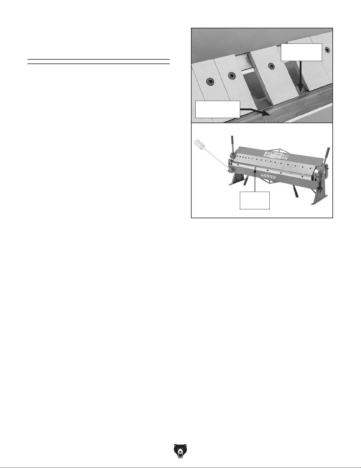
1.
bending leaf (see Figure 23) to determine if
they are out of alignment.
Loosen (5) hex bolts (see Figure 23) that
2.
secure bending block to bending leaf just
enough to move it up or down.
Top of
Bending Leaf
Top of
Bending Block
Hex Bolt
(1 of 5)
Figure 23. Location of hex bolts for aligning
bending block.
3. Align bending block flush with top of bending
leaf, and then tighten hex bolts.
-22-
Model G0950 (Mfd. Since 08/21)
Page 25
19
87
4
33
32
33
29
16
33
REF PART # DES CRIPTI ON RE F PART # DESCRIP TION
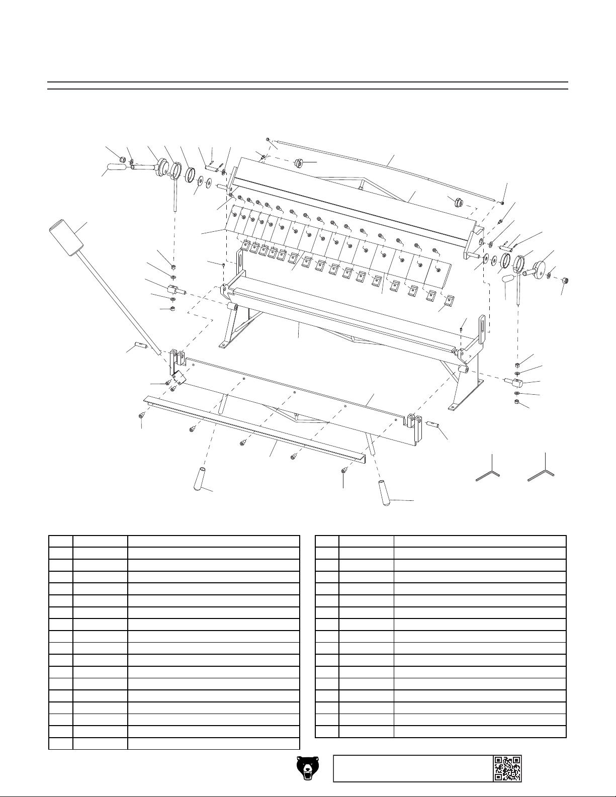
SECTION 7: PARTS
Main
28
20
24
14
10
17
14
1
18
31
9
31
30
30
22
11
27
23
12
17
22
13
15
27
2
24
33
19
16
5
6
8
28
32
30
31
26
3
9
31
30
25
18
34
35
21
29
1 P0950001 CLAMPING LEAF 19 P0950019 ROLL PIN 4 X 30
2 P0950002 STAND 20 P0950020 COUNTERWEI GHT
3 P0950003 BENDING LEAF 21 P0950021 BENDING BLOCK
4 P0950004 HANDLE (LEFT) 22 P0950022 FENDER WAS HER 16 MM
5 P0950005 HANDLE (RI GHT) 23 P0950023 CAP SCREW M10-1.5 X 30
6 P0950006 SWI VEL RO D (RI GHT) 24 P0950024 CAP SCREW M8-1.25 X 16
7 P0950007 SWIVEL ROD (LEFT) 25 P0950025 CAP SCREW M12-1.75 X 20
8 P0950008 SHAFT SLEEVE 26 P0950026 CAP SCREW M10-1.5 X 20
9 P0950009 CONNECTI NG SHAFT 27 P0950027 SET SCREW M8-1.25 X 12
10 P0950010 TENS I O N ROD 28 P0950028 UPPER HANDLE COVER
11 P0950011 CLAMPING FINGER 2" 29 P0950029 LOWER HANDLE COVER
12 P0950012 CLAMPING FINGER 3" 30 P0950030 HEX NUT M12-1.75
13 P0950013 CLAMPING FINGER 4" 31 P0950031 FLAT WASHER 12MM
14 P0950014 HEX NUT M8-1 . 2 5 32 P0950032 LO CK NUT M16-2
15 P0950015 TOE CLAMP M10-1.5 33 P0950033 FLAT WASHER 16MM
16 P0950016 ECCE NTRI C S HAFT 34 P0950034 HEX WRENCH 6MM
17 P0950017 ECCE NTRI C B USHI NG 35 P0950035 HEX WRENCH 8MM
18 P0950018 BENDING LEAF PIVOT SHAFT
Model G0950 (Mfd. Since 08/21)
25
BUY PARTS ONLINE AT GRIZZLY.COM !
Scan QR code to visit our Parts Store.
-23-
Page 26
We do our best to stock replacement parts when possible, but we cannot guarantee that all parts shown
are available for purchase. Call (800) 523-4777 or visit www.grizzly.com/parts to check for availability.
101
REF P ART # DES CRIPTION REF P ART # DES CRIPTION
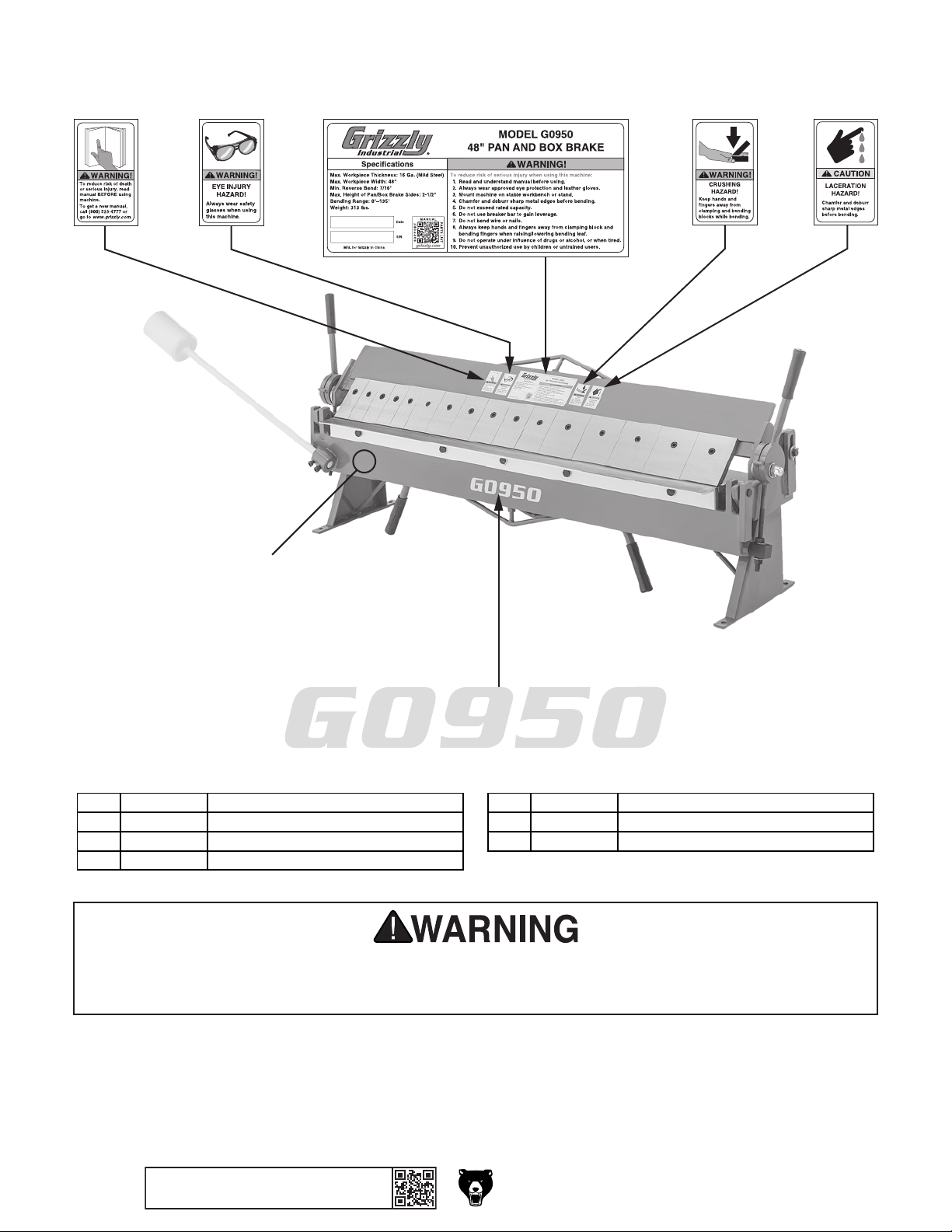
Labels & Cosmetics
102
104 105
103
107
106
101 P0950101 READ MANUAL LABEL 105 P0950105 LACERATION HAZARD LABEL
102 P0950102 WEAR GLASSES LABEL 106 P0950106 MODEL NUMBER LABEL
103 P0950103 MACHINE ID LABEL 107 P0950107 TOUCH-UP PAINT, G RI ZZL Y GREEN
104 P0950104 PINCH HAZA RD LAB EL
Safety labels help reduce the risk of serious injury caused by machine hazards. If any label comes
off or becomes unreadable, the owner of this machine MUST replace it in the original location
before resuming operations. For replacements, contact (800) 523-4777 or www.grizzly.com.
-24-
BUY PARTS ONLINE AT GRIZZLY.COM !
Scan QR code to visit our Parts Store.
Model G0950 (Mfd. Since 08/21)
Page 27

Grizzly Industrial, Inc. warrants every product it sells for a period of 1 year to the original purchaser from
the date of purchase. This warranty does not apply to defects due directly or indirectly to misuse, abuse,
negligence, accidents, repairs or alterations or lack of maintenance. This is Grizzly’s sole written warranty
and any and all warranties that may be implied by law, including any merchantability or fitness, for any particular purpose, are hereby limited to the duration of this written warranty. We do not warrant or represent
that the merchandise complies with the provisions of any law or acts unless the manufacturer so warrants.
In no event shall Grizzly’s liability under this warranty exceed the purchase price paid for the product and
any legal actions brought against Grizzly shall be tried in the State of Washington, County of Whatcom.
We shall in no event be liable for death, injuries to persons or property or for incidental, contingent, special,
or consequential damages arising from the use of our products.
The manufacturers reserve the right to change specifications at any time because they constantly strive to
achieve better quality equipment. We make every effort to ensure that our products meet high quality and
durability standards and we hope you never need to use this warranty.
In the event you need to use this warranty, contact us by mail or phone and give us all the details. We will
then issue you a “Return Number,’’ which must be clearly posted on the outside as well as the inside of
the carton. We will not accept any item back without this number. Proof of purchase must accompany the
merchandise.
Please feel free to write or call us if you have any questions about the machine or the manual.
Thank you again for your business and continued support. We hope to serve you again soon.
To
you can
applicable information for
WARRANTY & RETURNS
take advantage of this warranty, you must register it at https://www.grizzly.com/forms/warranty, or
scan the QR code below to be automatically directed to our warranty registration page. Enter all
the product.
WARRANTY
Page 28
 Loading...