

Page 1

MODEL G0949G
12" X 35" VARIABLE-SPEED
GUNSMITH LATHE
OWNER'S MANUAL
(For models manufactured since 01/22)
COPYRIGHT © DECEMBER, 2021 BY GRIZZLY INDUSTRIAL, INC., REVISED MAY, 2023 (JM)
WARNING: NO PORTION OF THIS MANUAL MAY BE REPRODUCED IN ANY SHAPE
OR FORM WITHOUT THE WRITTEN APPROVAL OF GRIZZLY INDUSTRIAL, INC.
#JM22163 PRINTED IN CHINA
***Keep for Future Reference***
V1.0 5.23
Page 2

This manual provides critical safety instructions on the proper setup,
operation, maintenance, and service of this machine/tool. Save this
document, refer to it often, and use it to instruct other operators.
Failure to read, understand and follow the instructions in this manual
may result in fire or serious personal injury—including amputation,
electrocution, or death.
The owner of this machine/tool is solely responsible for its safe use.
This responsibility includes but is not limited to proper installation in
a safe environment, personnel training and usage authorization,
proper inspection and maintenance, manual availability and comprehension, application of safety devices, cutting/sanding/grinding tool
integrity, and the usage of personal protective equipment.
The manufacturer will not be held liable for injury or property damage
from negligence, improper training, machine modifications or misuse.
Some dust created by power sanding, sawing, grinding, drilling, and
other construction activities contains chemicals known to the State
of California to cause cancer, birth defects or other reproductive
harm. Some examples of these chemicals are:
• Lead from lead-based paints.
• Crystalline silica from bricks, cement and other masonry products.
• Arsenic and chromium from chemically-treated lumber.
Your risk from these exposures varies, depending on how often you
do this type of work. To reduce your exposure to these chemicals:
Work in a well ventilated area, and work with approved safety equipment, such as those dust masks that are specially designed to filter
out microscopic particles.
Page 3

Table of Contents
INTRODUCTION ............................................... 2
Contact Info.................................................... 2
Manual Accuracy
Identification
Controls & Components
Glossary of Terms
Machine Data Sheet
SECTION 1: SAFETY
Safety Instructions for Machinery
Additional Safety for Metal Lathes
Additional Chuck Safety
SECTION 2: POWER SUPPLY
SECTION 3: SETUP
Preparation
Needed for Setup
Unpacking
Inventory
Cleanup
Site Considerations
Assembly
Anchoring to Floor
Leveling
Lubricating Lathe
Test Run
Spindle Break-In
Recommended Adjustments
SECTION 4: OPERATIONS
Operation Overview
Chuck & Faceplate Mounting....................... 30
Camlock Stud Installation
Chuck Safety & Support Devices
Chuck Installation......................................... 31
Chuck Removal............................................ 33
Scroll Chuck Clamping
Changing Jaw Set
4-Jaw Chuck
Faceplate
Tailstock
Centers
Steady Rest
Follow Rest
Carriage & Slide Locks
Compound Rest
Tool Post
Spindle Spider.............................................. 47
Manual Feed
Spindle Speed.............................................. 48
Power Feed.................................................. 49
End Gears
Threading
.................................................... 17
...................................................... 18
........................................................ 20
..................................................... 22
........................................................ 24
...................................................... 25
..................................................... 36
....................................................... 37
........................................................ 40
...................................................... 45
.................................................... 51
..................................................... 54
........................................... 2
................................................... 3
................................. 4
......................................... 7
...................................... 8
..................................... 11
................ 11
............... 13
............................... 14
...................... 15
....................................... 17
.................................................. 17
......................................... 17
...................................... 21
....................................... 24
......................................... 25
.......................................... 28
........................ 28
........................... 29
..................................... 29
............................ 30
................ 31
................................ 33
........................................ 34
................................................ 35
................................................. 43
.................................................. 44
................................ 44
........................................... 45
................................................ 47
SECTION 5: ACCESSORIES
SECTION 6: MAINTENANCE
Schedule
Cleaning/Protecting
Lubrication
Machine Storage
SECTION 7: SERVICE
Troubleshooting
Backlash Adjustment
Gib Adjustment
Half Nut Adjustment
Leadscrew End-Play Adjustment
V-Belt Tension & Replacement.................... 73
Leadscrew Shear Pin Replacement
Feed Clutch Adjustment
Bearing Preload
SECTION 8: WIRING
Wiring Safety Instructions
Wiring Overview
Electrical Cabinet Wiring
Electrical Cabinet
Motor
Control Panel
Variable Speed Dial & RPM Indicator.......... 85
SECTION 9: PARTS
Headstock
Gearbox
Carriage
Apron
Steady & Follow Rests................................. 94
Bed
Electrical Components
Accessories
Labels & Cosmetics (Front)
Labels & Cosmetics (Rear)
Change Gear System
SECTION 10: APPENDIX
G0949G Charts
WARRANTY & RETURNS
...................................................... 59
...................................... 59
................................................... 60
.......................................... 65
................................... 66
........................................... 66
................................... 69
............................................ 70
..................................... 72
........................................... 76
...................................... 79
........................................... 80
......................................... 82
............................................................ 83
............................................... 84
....................................... 86
.................................................... 86
....................................................... 88
....................................................... 90
........................................................... 92
............................................................... 97
................................................ 101
.......................................... 106
......................... 57
......................... 59
................. 72
............ 74
.............................. 75
............................ 79
.............................. 81
................................. 99
....................... 103
........................ 104
................................ 105
............................. 106
........................... 109
Page 4
INTRODUCTION
We are proud to provide a high-quality owner’s
manual with your new machine!
We
instructions, specifications, drawings, and photographs
in this manual. Sometimes we make mistakes, but
our policy of continuous improvement also means
that
you receive is
slightly different than shown in the manual
If you find this to be the case, and the difference
between the manual and machine leaves you
confused or unsure about something
check our
website for an updated version. W
current
manuals and
on our web-
site at
Alternatively, you can call our Technical Support
for help. Before calling, make sure you write
down the
serial number
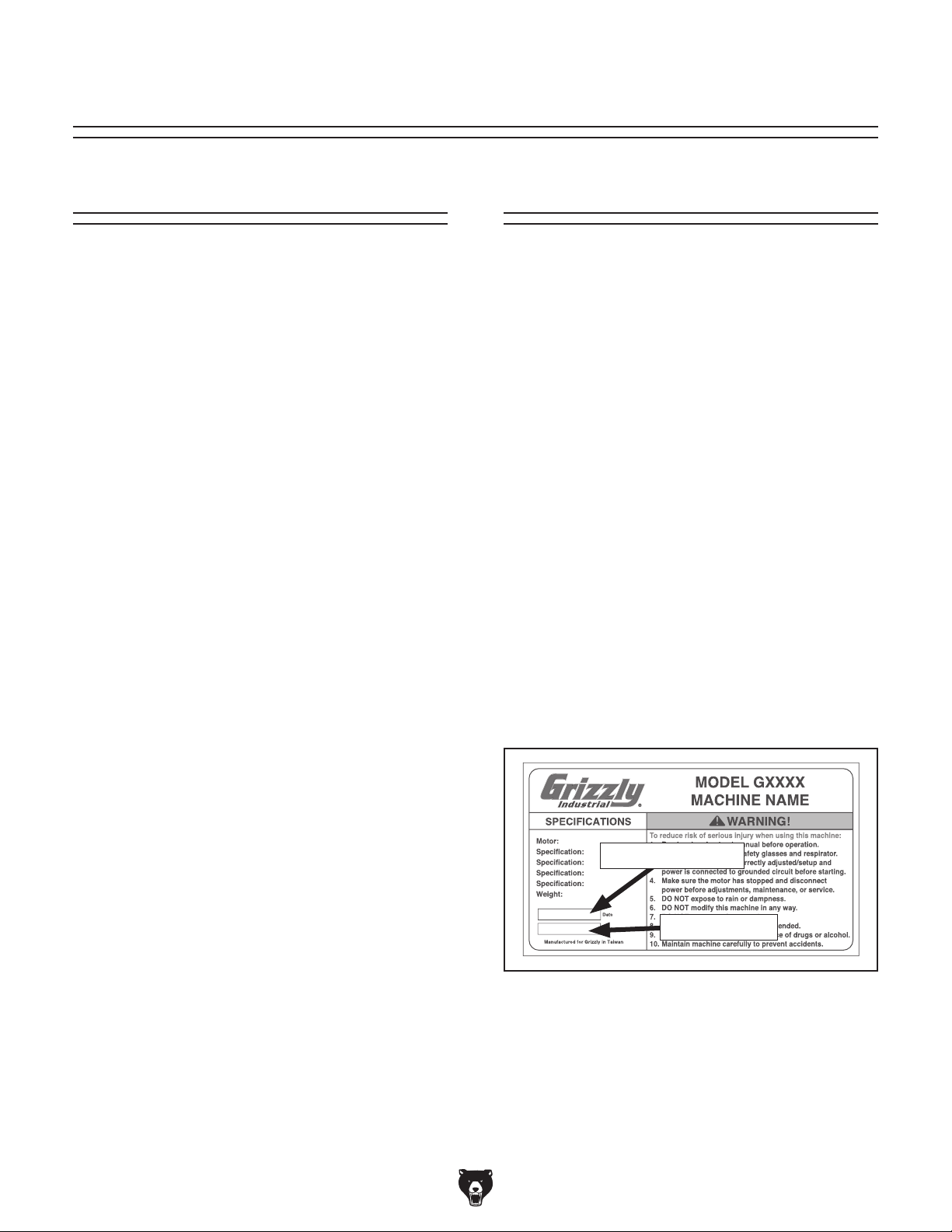
from the machine ID label (see below). This
information is required for us to provide proper
tech support, and it helps us determine if updated
documentation is available for your machine.
We stand behind our machines! If you have questions or need help, contact us with the information
below. Before contacting, make sure you get the
serial number
machine ID label. This will help us help you faster.
We want your feedback on this manual. What did
you like about it? Where could it be improved?
Please take a few minutes to give us feedback.
Email: [email protected]
Contact Info
and manufacture date from the
Grizzly Technical Support
1815 W. Battlefield
Springfield, MO 65807
Phone: (570) 546-9663
Email: [email protected]
Grizzly Documentation Manager
P.O. Box 2069
Bellingham, WA 98227-2069
Manual Accuracy
made every effort to be exact with the
sometimes the machine
.
,
e post
manual updates for free
www.grizzly.com.
manufacture date and
Manufacture Date
Serial Number
-2-
Model G0949G (Mfd. Since 01/22)
Page 5
To reduce your risk of
serious injury, read this
entire manual BEFORE
Identification
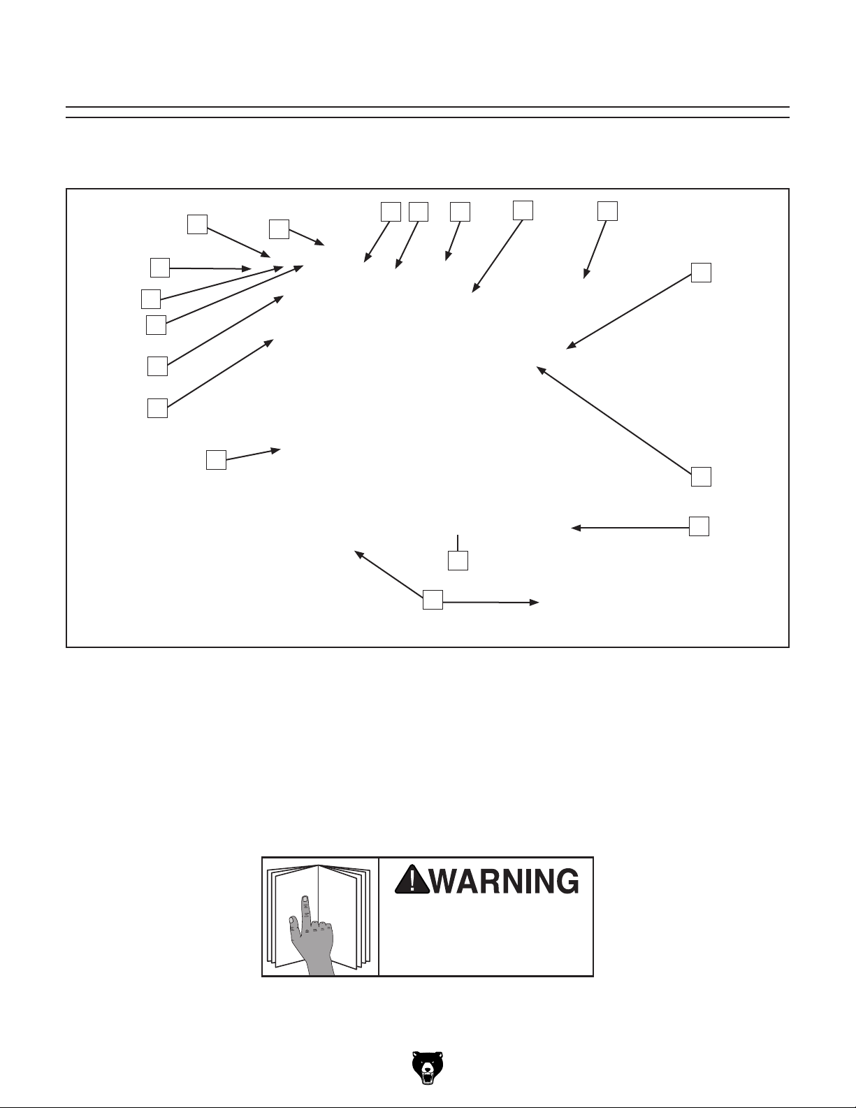
Become familiar with the names and locations of the controls and features shown below to better understand
the instructions in this manual.
Q
P
O
N
C
A
R
M
B
D
E
L
K
F
G
H
I
J
A. Headstock
B. Master Power Switch
C. 3-Jaw Chuck 6"
D. Steady Rest
E. Quick-Change Tool Post
F. Compound Rest
G. Tailstock
H. Leadscrew
I. Feed Rod
Model G0949G (Mfd. Since 01/22)
J. Storage Cabinet
K. Stand Mounting Points
L. Carriage
M. 3-Drawer Cabinet
Quick-Change Gearbox Levers
N.
O. Spindle Speed Range Lever
P. Spindle Speed Dial
Q. Spindle Speed Digital Readout
R. Change Gear and Belt Safety Cover
using machine.
-3-
Page 6
Controls &
To reduce your risk of
serious injury, read this
entire manual BEFORE
using machine.
Components
Headstock
A
B
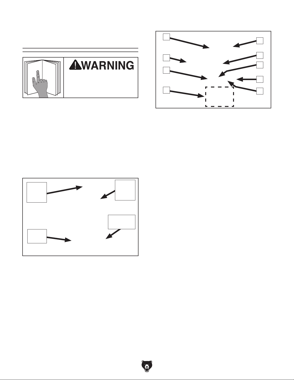
Refer to Figures 1-6 and the following descrip-
tions to become familiar with the basic controls of
this lathe.
Many of the controls will be explained in greater
detail later in this manual.
Master Power Switch
The rotary switch shown in Figure 1 toggles
incoming power ON and OFF to the lathe controls.
Master
Power
Switch
E-Stop
Button
Spindle
Speed
Dial
FWD/REV
Switch
I
H
G
Figure 2. Headstock controls.
A. Spindle Speed Digital Readout: Shows
spindle speed RPM.
B. Spindle Speed Dial: Turn clockwise to
increase spindle speed. Turn counterclockwise to decrease spindle speed.
C. Spindle Speed Range Lever: Selects one of
two spindle speed ranges.
D. START Button: Starts spindle rotation.
Illuminates when power is ON.
E. FWD/REV Switch: Once spindle has come to
a complete stop, move switch to FWD position for counterclockwise rotation (forward).
Move switch to REV position for clockwise
rotation (reverse). Move switch to "0" position
to stop spindle rotation.
C
D
E
F
Figure 1. Master power switch location.
-4-
F. STOP Button: Stops spindle rotation.
G. Quick-Change Gearbox Levers: Controls
leadscrew and feed rod speeds for threading
and feeding operations.
H. E-Stop Button: Stops all machine functions.
Twist clockwise to reset.
Thread and Feed Charts: Display necessary
I.
configuration of gearbox dials and end gears
for threading or feeding options.
Model G0949G (Mfd. Since 01/22)
Page 7

Carriage
L. Carriage Lock: Secures carriage in place for
greater rigidity.
J
Q
P
O
Figure 3. Carriage controls.
J. Quick-Change Tool Post: Allows operator
to quickly load and unload tools/tool holders.
K. Compound Rest Handwheel: Moves tool
towards or away from workpiece at preset
angle of compound rest. Dial is graduated in
increments of 0.001" (0.1" per full revolution).
K
L
M
N
M. Thread Dial: Indicates when to engage the
half nut during inch threading operations.
N. Half-Nut Lever: Engages/disengages half
nut for threading operations.
Feed Selection Lever: Selects power feed
O.
for carriage or cross slide.
P. Carriage Handwheel: Moves carriage along
bed. Dial is graduated in increments of 0.01"
(1.2" per full revolution).
Cross Slide Handwheel: Moves cross slide
Q.
towards or away from workpiece. Dial is
graduated in increments of 0.002" (0.2" per
full revolution).
Model G0949G (Mfd. Since 01/22)
-5-
Page 8
Tailstock
S
R
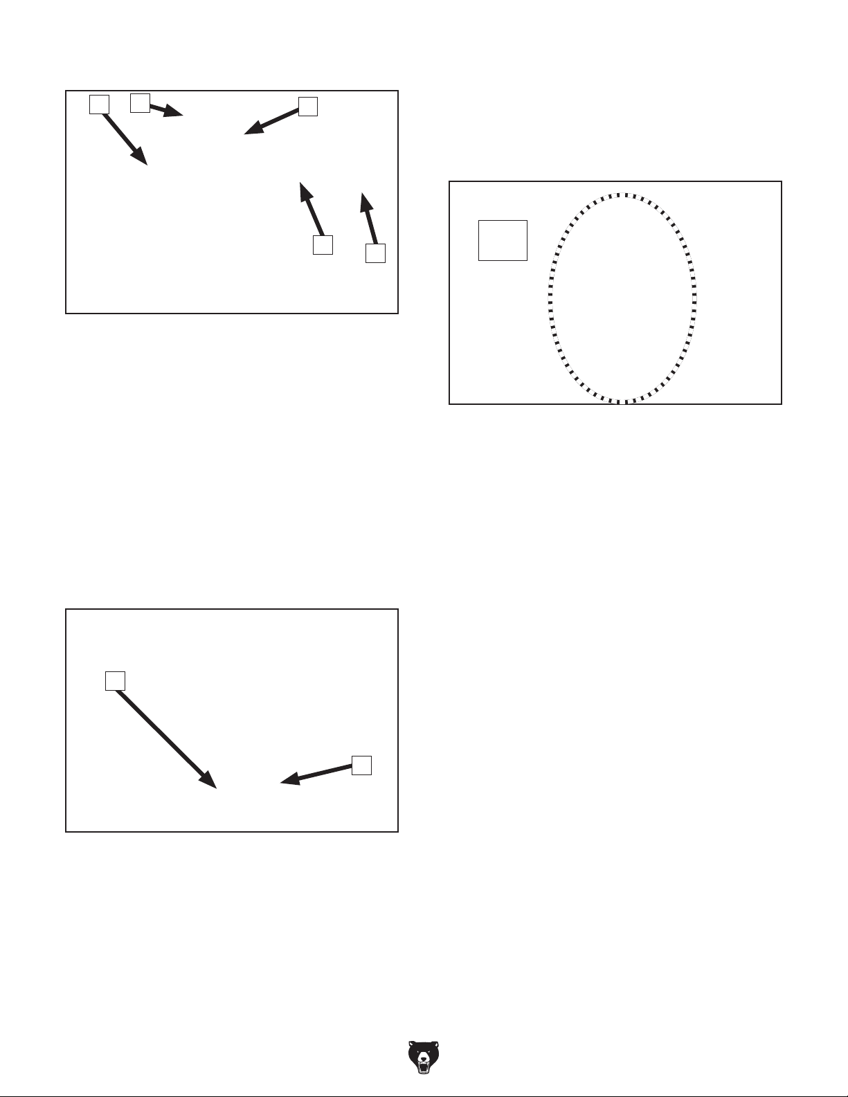
Figure 4. Tailstock controls.
R. Quill: Holds centers and tooling.
S. Quill Lock Lever: Secures quill in position.
T. Tailstock Lock Lever: Secures tailstock in
position along bedway.
T
U
V
V
W
End Gears
Configuring the end gears (shown in Figure 6)
controls the speed of the leadscrew for threading operations, or the feed rod for power feed
operations.
End
Gears
Figure 6. End gear components.
U. Graduated Scale: Indicates quill movement
in increments of 0.001" with one full revolu-
tion equaling 0.1" of quill travel.
V. Quill Handwheel: Moves quill toward or
away from spindle.
W
X
Figure 5. Additional tailstock controls.
W. Tailstock Offset Screw: Offsets tailstock
left or right from spindle centerline (1 of 2).
X. Offset Scale: Indicates relative distance of
tailstock offset from spindle centerline.
-6-
Model G0949G (Mfd. Since 01/22)
Page 9

Glossary of Terms
The following is a list of common definitions, terms and phrases used throughout this manual as they relate
to this lathe and metalworking in general. Become familiar with these terms for assembling, adjusting or
operating this machine. Your safety is VERY important to us at Grizzly!
Arbor: A machine shaft that supports a cutting
tool.
Backlash: Wear in a screw or gear mechanism
that may result in slippage, vibration, and loss
of tolerance.
Carriage: A main housing that consists of the
apron and the saddle.
Cross Slide: A fixture attached to the lathe car-
riage that holds the compound rest and can be
moved in and out.
Compound Rest: A fixture attached to the cross
slide that holds the tool holder and can be
moved in and out.
Cutting Speed: The distance a point on a cutter
moves in one minute, expressed in meters or
feet per minute.
Dial Indicator: An instrument used in setup
and inspection work that shows on a dial the
amount of error in size or alignment of a part.
Facing: In lathe work, cutting across the end of
a workpiece, usually to machine a flat surface.
Feed: The movement of a cutting tool into a
workpiece.
Fixture: A device that securely holds the
workpiece in place during cutting operation
as opposed to a jig which is used to hold and
guide a workpiece through an operation.
Gib: A tapered wedge located along a sliding
member to take up wear or to ensure a proper
fit.
Headstock: The major lathe component that
houses the spindle and motor drive system to
turn the workpiece.
Lathe Center: A lathe accessory with a 60°
point which is inserted into the headstock or
tailstock of the lathe and is used to support the
workpiece.
Leadscrew: Lathe—The long screw that is driven
by the change gears and supplies power to the
carriage.
Saddle: The upper portion of carriage that rides
on the lathe ways and supports the cross feed
and the follow rest.
Spindle: The revolving shaft that holds and drives
the workpiece or cutting tool.
Tailstock: A moveable fixture opposite of the
headstock on a lathe that has a spindle used to
support one end of a workpiece and for holding
tools.
Tool Post: The part of the compound rest that
holds the tool holder.
Turret : Lathe—A machine fixture that holds mul-
tiple tools and can be revolved and indexed to
position.
Ways: The precision machined and flat tracks
on a lathe on which the carriage and tailstock
slide.
Model G0949G (Mfd. Since 01/22)
-7-
Page 10

MACHINE DATA
SHEET
Customer Service #: (570) 546-9663 · To Order Call: (800) 523-4777 · Fax #: (800) 438-5901
MODEL G0949G 12" X 35" VARIABLE‐SPEED GUNSMITH
LATHE
Product Dimensions:
Weight.............................................................................................................................................................. 772 lbs.
Width (side-to-side) x Depth (front-to-back) x Height..................................................................... 65 x 30-1/2 x 53 in.
Footprint (Length x Width)..................................................................................................................... 58-1/2 x 15 in.
Shipping Dimensions:
Carton #1
Type................................................................................................................................................ Wood Crate
Content................................................................................................................................................. Machine
Weight.................................................................................................................................................... 717 lbs.
Length x Width x Height............................................................................................................. 65 x 30 x 30 in.
Must Ship Upright......................................................................................................................................... Yes
Carton #2
Type................................................................................................................................................ Wood Pallet
Content...................................................................................................................................................... Stand
Weight.................................................................................................................................................... 133 lbs.
Length x Width x Height............................................................................................................. 32 x 24 x 20 in.
Must Ship Upright......................................................................................................................................... Yes
Electrical:
Power Requirement........................................................................................................... 110V, Single-Phase, 60 Hz
Full-Load Current Rating........................................................................................................................................ 15A
Minimum Circuit Size.............................................................................................................................................. 20A
Connection Type....................................................................................................................................... Cord & Plug
Power Cord Included.............................................................................................................................................. Yes
Power Cord Length.............................................................................................................................................. 60 in.
Power Cord Gauge......................................................................................................................................... 14 AWG
Plug Included.......................................................................................................................................................... Yes
Included Plug Type................................................................................................................................................ 5-15
Switch Type.............................................................................................................................. START/STOP Buttons
-8-
Motors:
Main
Horsepower............................................................................................................................................. 1.5 HP
Phase............................................................................................................................................ Single-Phase
Amps............................................................................................................................................................ 15A
Speed................................................................................................................................................ 3400 RPM
Type.............................................................................................................................................. DC Brushless
Power Transfer ............................................................................................................................................ Belt
Bearings..................................................................................................... Shielded & Permanently Lubricated
Model G0949G (Mfd. Since 01/22)
Page 11

Main Specifications:
Operation Info
Swing Over Bed................................................................................................................................... 12-5/8 in.
Distance Between Centers.................................................................................................................. 34-5/8 in.
Swing Over Cross Slide......................................................................................................................... 7-3/4 in.
Swing Over Saddle.............................................................................................................................. 10-1/2 in.
Maximum Tool Bit Size............................................................................................................................. 5/8 in.
Compound Travel.................................................................................................................................. 3-3/8 in.
Carriage Travel.................................................................................................................................. 33-7/16 in.
Cross Slide Travel................................................................................................................................. 6-1/2 in.
Headstock Info
Spindle Bore............................................................................................................................................. 1.5 in.
Spindle Taper............................................................................................................................................ MT#5
Spindle Threads............................................................................................................................ M48 x 1.5mm
Number of Spindle Speeds............................................................................................................................... 2
Spindle Speeds....................................................................................................... 100 - 515, 390 - 2000 RPM
Spindle Type................................................................................................................................ D1-4 Camlock
Spindle Bearings......................................................................................................................... Tapered Roller
Spindle Length..................................................................................................................................... 14-3/4 in.
Spindle Length with 3-Jaw Chuck....................................................................................................... 18-3/8 in.
Spindle Length with 4-Jaw Chuck................................................................................................... 19-13/16 in.
Spindle Length with Faceplate........................................................................................................ 15-13/16 in.
Tailstock Info
Tailstock Quill Travel............................................................................................................................. 3-1/8 in.
Tailstock Taper.......................................................................................................................................... MT#3
Tailstock Barrel Diameter..................................................................................................................... 1.261 in.
Threading Info
Number of Longitudinal Feeds....................................................................................................................... 12
Range of Longitudinal Feeds........................................................................................... 0.0025 - 0.012 in./rev.
Number of Cross Feeds................................................................................................................................. 10
Range of Cross Feeds................................................................................................... 0.0015 - 0.0056 in./rev.
Number of Inch Threads................................................................................................................................. 21
Range of Inch Threads....................................................................................................................... 8 - 56 TPI
Number of Metric Threads.............................................................................................................................. 12
Range of Metric Threads................................................................................................................. 0.4 - 3.5mm
Dimensions
Bed Width.................................................................................................................................................... 7 in.
Carriage Leadscrew Diameter.............................................................................................................. 13/16 in.
Leadscrew TPI.................................................................................................................................................. 8
Carriage Leadscrew Length.............................................................................................................. 47-7/16 in.
Steady Rest Capacity.................................................................................................................................. 2 in.
Follow Rest Capacity................................................................................................................................... 2 in.
Faceplate Size....................................................................................................................................... 9-3/8 in.
Feed Rod Diameter.............................................................................................................................. 11/16 in.
Floor to Center Height......................................................................................................................... 46-1/2 in.
Other
Carriage Handwheel Graduations.......................................................................................................... 0.01 in.
Carriage Handwheel Revolution............................................................................................................... 1.2 in.
Cross Slide Handwheel Graduations.................................................................................................... 0.002 in.
Cross Slide Handwheel Revolution.......................................................................................................... 0.2 in.
Compound Handwheel Graduations..................................................................................................... 0.001 in.
Compound Handwheel Revolution........................................................................................................... 0.1 in.
Tailstock Handwheel Graduations........................................................................................................ 0.001 in.
Tailstock Handwheel Revolution............................................................................................................... 0.1 in.
Model G0949G (Mfd. Since 01/22)
-9-
Page 12

Construction
Base........................................................................................................................................................... Steel
Headstock............................................................................................................................................ Cast Iron
End Gears...................................................................................................................... Flame-Hardened Steel
Bed...................................................................................................................... Induction-Hardened Cast Iron
Body..................................................................................................................................................... Cast Iron
Stand.......................................................................................................................................................... Steel
Paint Type/Finish...................................................................................................................................... Epoxy
Fluid Capacities
Headstock Capacity.................................................................................................................................. 27 oz.
Headstock Fluid Type................................................................ ISO 32 (eg. Grizzly T23963, Mobil DTE Light)
Gearbox Capacity.................................................................................................................................. 13.5 oz.
Gearbox Fluid Type...................................................................... ISO 68 (eg. Grizzly T23962, Mobil Vactra 2)
Apron Capacity...................................................................................................................................... 6.75 oz.
Apron Fluid Type.......................................................................... ISO 68 (eg. Grizzly T23962, Mobil Vactra 2)
Other Specifications:
Country of Origin ................................................................................................................................................ China
Warranty ........................................................................................................................................................... 1 Year
Approximate Assembly & Setup Time .............................................................................................................. 1 Hour
Serial Number Location ................................................................................................................... Machine ID Label
ISO 9001 Factory .................................................................................................................................................. Yes
Features:
Digital Spindle Speed Readout
Outboard Spindle Support Spider with 4 Brass-Tipped Bolts
D1-4 Camlock Spindle
Full-Length Splash Guard
200-Series Quick-Change Tool Post
Steady and Follow Rests with Brass Supports
Stand with 3 Storage Drawers and 1 Cabinet
Variable-Speed Control Through 2 Speed Ranges
Accessories Included:
6" 3-Jaw Universal Chuck with 2 Sets of Jaws
6" 4-Jaw Independent Chuck with Reversible Jaws
9-3/8" Faceplate
200-Series Quick-Change Tool Post with 2 Holders
Steady and Follow Rests with Brass Supports
MT#5 - MT#3 Adapter Sleeve
(2) MT#3 Dead Centers
Set of 10 Change Gears
Toolbox with Service Tools
-10 -
Model G0949G (Mfd. Since 01/22)
Page 13
SECTION 1: SAFETY
For Your Own Safety, Read Instruction
Manual Before Operating This Machine
The purpose of safety symbols is to attract your attention to possible hazardous conditions.
This manual uses a series of symbols and signal words intended to convey the level of importance of the safety messages. The progression of symbols is described below. Remember that
safety messages by themselves do not eliminate danger and are not a substitute for proper
accident prevention measures. Always use common sense and good judgment.
Indicates an imminently hazardous situation which, if not avoided,
WILL result in death or serious injury.
Indicates a potentially hazardous situation which, if not avoided,
COULD result in death or serious injury.
Indicates a potentially hazardous situation which, if not avoided,
MAY result in minor or moderate injury. It may also be used to alert
against unsafe practices.
Alerts the user to useful information about proper operation of the
NOTICE
machine to avoid machine damage.
Safety Instructions for Machinery
OWNER’S MANUAL. Read and understand this
owner’s manual BEFORE using machine.
TRAINED OPERATORS ONLY. Untrained operators have a higher risk of being hurt or killed.
Only allow trained/supervised people to use this
machine. When machine is not being used, disconnect power, remove switch keys, or lock-out
machine to prevent unauthorized use—especially
around children. Make your workshop kid proof!
DANGEROUS ENVIRONMENTS. Do not use
machinery in areas that are wet, cluttered, or have
poor lighting. Operating machinery in these areas
greatly increases the risk of accidents and injury.
MENTAL ALERTNESS REQUIRED. Full mental
alertness is required for safe operation of machinery. Never operate under the influence of drugs or
alcohol, when tired, or when distracted.
ELECTRICAL EQUIPMENT INJURY RISKS.
You can be shocked, burned, or killed by touching
live electrical components or improperly grounded
machinery. To reduce this risk, only allow qualified
service personnel to do electrical installation or
repair work, and always disconnect power before
accessing or exposing electrical equipment.
DISCONNECT POWER FIRST.
nect machine from power supply BEFORE making adjustments, changing tooling, or servicing
machine. This prevents an injury risk from unintended startup or contact with live electrical components.
EYE PROTECTION. Always wear ANSI-approved
safety glasses or a face shield when operating or
observing machinery to reduce the risk of eye
injury or blindness from flying particles. Everyday
eyeglasses are NOT approved safety glasses.
Always discon-
Model G0949G (Mfd. Since 01/22)
-11-
Page 14

WEARING PROPER APPAREL. Do not wear
clothing, apparel or jewelry that can become
entangled in moving parts. Always tie back or
cover long hair. Wear non-slip footwear to reduce
risk of slipping and losing control or accidentally
contacting cutting tool or moving parts.
HAZARDOUS DUST. Dust created by machinery
operations may cause cancer, birth defects, or
long-term respiratory damage. Be aware of dust
hazards associated with each workpiece material. Always wear a NIOSH-approved respirator to
reduce your risk.
HEARING PROTECTION. Always wear hearing protection when operating or observing loud
machinery. Extended exposure to this noise
without hearing protection can cause permanent
hearing loss.
REMOVE ADJUSTING TOOLS. Tools left on
machinery can become dangerous projectiles
upon startup. Never leave chuck keys, wrenches,
or any other tools on machine. Always verify
removal before starting!
USE CORRECT TOOL FOR THE JOB. Only use
this tool for its intended purpose—do not force
it or an attachment to do a job for which it was
not designed. Never make unapproved modifications—modifying tool or using it differently than
intended may result in malfunction or mechanical
failure that can lead to personal injury or death!
AWKWARD POSITIONS. Keep proper footing
and balance at all times when operating machine.
Do not overreach! Avoid awkward hand positions
that make workpiece control difficult or increase
the risk of accidental injury.
CHILDREN & BYSTANDERS. Keep children and
bystanders at a safe distance from the work area.
Stop using machine if they become a distraction.
GUARDS & COVERS. Guards and covers reduce
accidental contact with moving parts or flying
debris. Make sure they are properly installed,
undamaged, and working correctly BEFORE
operating machine.
FORCING MACHINERY. Do not force machine.
It will do the job safer and better at the rate for
which it was designed.
NEVER STAND ON MACHINE. Serious injury
may occur if machine is tipped or if the cutting
tool is unintentionally contacted.
STABLE MACHINE. Unexpected movement during operation greatly increases risk of injury or
loss of control. Before starting, verify machine is
stable and mobile base (if used) is locked.
USE RECOMMENDED ACCESSORIES. Consult
this owner’s manual or the manufacturer for recommended accessories. Using improper accessories will increase the risk of serious injury.
UNATTENDED OPERATION. To reduce the
risk of accidental injury, turn machine OFF and
ensure all moving parts completely stop before
walking away. Never leave machine running
while unattended.
MAINTAIN WITH CARE. Follow all maintenance
instructions and lubrication schedules to keep
machine in good working condition. A machine
that is improperly maintained could malfunction,
leading to serious personal injury or death.
DAMAGED PARTS. Regularly inspect machine
for damaged, loose, or mis-adjusted parts—or
any condition that could affect safe operation.
Immediately repair/replace BEFORE operating
machine. For your own safety, DO NOT operate
machine with damaged parts!
MAINTAIN POWER CORDS. When disconnecting cord-connected machines from power, grab
and pull the plug—NOT the cord. Pulling the cord
may damage the wires inside. Do not handle
cord/plug with wet hands. Avoid cord damage by
keeping it away from heated surfaces, high traffic
areas, harsh chemicals, and wet/damp locations.
EXPERIENCING DIFFICULTIES. If at any time
you experience difficulties performing the intended operation, stop using the machine! Contact our
Technical Support at (570) 546-9663.
-12-
Model G0949G (Mfd. Since 01/22)
Page 15

Additional Safety for Metal Lathes
Serious injury or death can occur from getting entangled in, crushed between, or struck by
rotating parts on a lathe! Unsecured tools or workpieces that fly loose from rotating objects
can also strike nearby operators with deadly force. To minimize the risk of getting hurt or killed,
anyone operating this machine MUST completely heed the hazards and warnings below.
CLOTHING, JEWELRY & LONG HAIR. Tie back
long hair, remove jewelry, and do not wear loose
clothing or gloves. These can easily get caught on
rotating parts and pull you into lathe.
ROTAT ING PARTS. Always keep hands and body
at a safe distance from rotating parts—especially
those with projecting surfaces. Never hold anything against rotating workpiece, such as emery
cloth, that can pull you into lathe.
GUARDING. Guards and covers protect against
entanglement or flying objects. Always ensure they
are properly installed while machine is running.
ADJUSTMENT TOOLS. Remove all chuck keys,
wrenches, and adjustment tools before turning
lathe ON. A tool left on the lathe can become a
deadly projectile when spindle is started.
SAFE CLEARANCES. Before starting spindle,
verify workpiece has adequate clearance by handrotating it through its entire range of motion.
NEW SETUPS. Test each new setup by starting
spindle rotation at the lowest speed and standing
to the side of the lathe until workpiece reaches full
speed and you can verify safe rotation.
SPINDLE SPEEDS. Using spindle speeds that are
too fast for the workpiece or clamping equipment
can cause rotating parts to come loose and strike
nearby people with deadly force. Always use slow
spindle speeds with large or non-concentric workpieces. Never exceed rated RPM of the chuck.
LONG STOCK SAFETY. Long stock can whip
violently if not properly supported. Always support
any stock that extends from the chuck/headstock
more than three times its own diameter.
CLEARING CHIPS. Metal chips can be razor
sharp. Avoid clearing them by hand or with a rag.
Use a brush or vacuum instead.
SECURE WORKPIECE. An improperly secured
workpiece can fly off spindle with deadly force.
Make sure workpiece is properly secured before
starting the lathe.
CHUCKS. Chucks can be heavy and difficult to
hold. During installation and removal, protect your
hands and precision bed ways by using a chuck
cradle or piece of plywood over the bed ways. Use
lifting equipment, as necessary, for large chucks.
STOPPING SPINDLE. Always allow spindle to
completely stop on its own, or use a brake, if
provided. Never put hands or another object on a
spinning workpiece to make it stop faster.
CRASHING. A serious explosion of metal parts
can occur if cutting tool or other lathe component
hits rotating chuck or a projecting part of workpiece. Resulting metal fragments can strike nearby
people and lathe will be seriously damaged. To
reduce risk of crashing, ALWAYS release automatic feeds after use, NEVER leave lathe unattended,
and CHECK all clearances before starting lathe.
COOLANT SAFETY. Coolant can become very
toxic through prolonged use and aging. To minimize toxicity, change coolant regularly. When
using, position nozzle properly to avoid splashing
operator or causing a slipping hazard on floor.
TOOL SELECTION. Cutting with incorrect or dull
tooling increases risk of injury from broken or dislodged components, or as a result of extra force
required for operation. Always use sharp tooling
that is right for the job.
SANDING/POLISHING. To reduce risk of entanglement, never wrap emery cloth around rotating
workpiece. Instead, use emery cloth with the aid
of a tool or backing board.
MEASURING WORKPIECE. To reduce risk of
entanglement, never measure rotating workpieces.
Model G0949G (Mfd. Since 01/22)
-13-
Page 16
Additional Chuck Safety
ENTANGLEMENT. Entanglement with a rotat-
ing chuck can lead to death, amputation, broken
bones, or other serious injury. Never attempt to
slow or stop the lathe chuck by hand, and always
roll up long sleeves, tie back long hair, and remove
any jewelry or loose apparel BEFORE operating.
CHUCK SPEED RATING. Excessive spindle
speeds greatly increase the risk of the workpiece
or chuck being thrown from the machine with
deadly force. Never use spindle speeds faster than
the chuck RPM rating or the safe limits of your
workpiece.
USING CORRECT EQUIPMENT. Many workpieces can only be safely turned in a lathe if additional
support equipment, such as a tailstock or steady/
follow rest, is used. If the operation is too hazardous to be completed with the lathe or existing
equipment, the operator must have enough experience to know when to use a different machine or
find a safer way.
TRAINED OPERATORS ONLY. Using a chuck
incorrectly can result in workpieces coming loose
at high speeds and striking the operator or bystanders with deadly force. To reduce the risk of this hazard, read and understand this document and seek
additional training from an experienced chuck user
before using a chuck.
CHUCK CAPACITY. Avoid exceeding the capacity
of the chuck by clamping an oversized workpiece.
If the workpiece is too large to safely clamp with
the chuck, use a faceplate or a larger chuck if possible. Otherwise, the workpiece could be thrown
from the lathe during operation, resulting in serious
impact injury or death.
CLAMPING FORCE. Inadequate clamping force
can lead to the workpiece being thrown from the
chuck and striking the operator or bystanders.
Maximum clamping force is achieved when the
chuck is properly maintained and lubricated, all
jaws are fully engaged with the workpiece, and
the maximum chuck clamping diameter is not
exceeded.
PROPER MAINTENANCE. All chucks must be
properly maintained and lubricated to achieve
maximum clamping force and withstand the rigors
of centrifugal force. To reduce the risk of a thrown
workpiece, follow all maintenance intervals and
instructions in this document.
DISCONNECT POWER. Serious entanglement or
impact injuries could occur if the lathe is started
while you are adjusting, servicing, or installing the
chuck. Always disconnect the lathe from power
before performing these procedures.
Like all machines there is danger associated
with Model G0949G. Accidents are frequently caused by lack of familiarity or failure to
pay attention. Use this machine with respect
and caution to lessen the possibility of
operator injury. If normal safety precautions
are overlooked or ignored, serious personal
injury may occur.
-14-
No list of safety guidelines can be complete.
Every shop environment is different. Always
consider safety first, as it applies to your
individual working conditions. Use this and
other machinery with caution and respect.
Failure to do so could result in serious personal injury, damage to equipment, or poor
work results.
Model G0949G (Mfd. Since 01/22)
Page 17
SECTION 2: POWER SUPPLY
Before installing the machine, consider the availability and proximity of the required power supply
circuit. If an existing circuit does not meet the
requirements for this machine, a new circuit must
be installed. To minimize the risk of electrocution,
fire, or equipment damage, installation work and
electrical wiring must be done by an electrician or
qualified service personnel in accordance with all
applicable codes and standards.
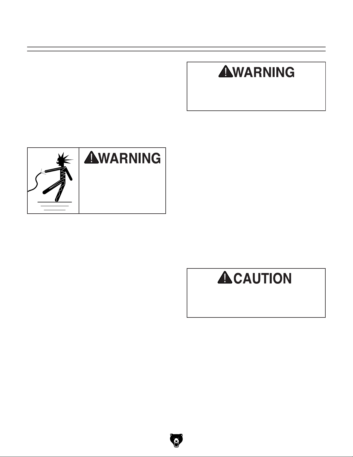
or equipment damage
may occur if machine is
not properly grounded
and connected to power
The full-load current rating is the amperage a
machine draws at 100% of the rated output power.
On machines with multiple motors, this is the
amperage drawn by the largest motor or sum of all
motors and electrical devices that might operate
at one time during normal operations.
The full-load current is not the maximum amount
of amps that the machine will draw. If the machine
is overloaded, it will draw additional amps beyond
the full-load rating.
If the machine is overloaded for a sufficient length
of time, damage, overheating, or fire may result—
especially if connected to an undersized circuit.
To reduce the risk of these hazards, avoid overloading the machine during operation and make
sure it is connected to a power supply circuit that
meets the specified circuit requirements.
For your own safety and protection of
Note: Circuit requirements in this manual apply to
a dedicated circuit—where only one machine will
be running on the circuit at a time. If machine will
be connected to a shared circuit where multiple
machines may be running at the same time, consult an electrician or qualified service personnel to
ensure circuit is properly sized for safe operation.
A power supply circuit includes all electrical
equipment between the breaker box or fuse panel
in the building and the machine. The power supply circuit used for this machine must be sized to
safely handle the full-load current drawn from the
machine for an extended period of time. (If this
machine is connected to a circuit protected by
fuses, use a time delay fuse marked D.)
This machine is prewired to operate on a power
supply circuit that has a verified ground and meets
the following requirements:
process. DO NOT connect to power until
Availability
Electrocution, fire, shock,
Serious injury could occur if you connect
machine to power before completing setup
instructed later in this manual.
110V Circuit Requirements
Nominal Voltage .................... 110V, 115V, 120V
..........................................................60 Hz
Cycle
Phase
Power Supply Circuit
Plug Receptacle
........................................... Single-Phase
......................... 20 Amps
.............................. NEMA 5-15
supply.
Full-Load Current Rating
Full-Load Current Rating at 110V ...... 15 Amps
Model G0949G (Mfd. Since 01/22)
property, consult an electrician if you are
unsure about wiring practices or electrical
codes in your area.
-15-
Page 18

Improper connection of the equipment-grounding
wire can result in a risk of electric shock. The
wire with green insulation (with or without yellow
stripes) is the equipment-grounding wire. If repair
or replacement of the power cord or plug is necessary, do not connect the equipment-grounding
wire to a live (current carrying) terminal.
Check with a qualified electrician or service personnel if you do not understand these grounding
requirements, or if you are in doubt about whether
the tool is properly grounded. If you ever notice
that a cord or plug is damaged or worn, disconnect it from power, and immediately replace it with
a new one.
We do not recommend using an extension cord
with this machine.
cord, only use it if absolutely necessary and only
on a temporary basis.
Extension cords cause voltage drop, which can
damage electrical components and shorten motor
life. Voltage drop increases as the extension cord
size gets longer and the gauge size gets smaller
(higher gauge numbers indicate smaller sizes).
Any extension cord used with this machine must
be in good condition and contain a ground wire
and matching plug/receptacle. Additionally, it must
meet the following size requirements:
Grounding & Plug Requirements
it will not fit the outlet, have a qualified
electrician install the proper outlet with a
This machine MUST be grounded. In the event
of certain malfunctions or breakdowns, grounding
reduces the risk of electric shock by providing a
path of least resistance for electric current.
This machine is equipped with a power cord that
has an equipment-grounding wire and a grounding
plug. Only insert plug into a matching receptacle
(outlet) that is properly installed and grounded in
accordance with all local codes and ordinances.
DO NOT modify the provided plug!
GROUNDED
5-15 RECEPTACLE
Grounding Pin
5-15 PLUG
Extension Cords
If you must use an extension
Neutral Hot
Figure 7. Typical 5-15 plug and receptacle.
SHOCK HAZARD!
Two-prong outlets do not meet the grounding
requirements for this machine. Do not modify
or use an adapter on the plug provided—if
verified ground.
-16 -
Minimum Gauge Size ...........................12 AWG
Maximum Length (Shorter is Better).......50 ft.
Model G0949G (Mfd. Since 01/22)
Page 19

SECTION 3: SETUP
This machine was carefully packaged for safe
transport. When unpacking, separate all enclosed
items from packaging materials and inspect them
for shipping damage.
,
please
IMPORTANT:
you are completely satisfied with the machine and
have resolved any issues between Grizzly or the
shipping agent. You MUST have the original pack-
aging to file a freight claim. It is also extremely
helpful if you need to return your machine later.
Preparation
The list below outlines the basic process of preparing your machine for operation. Specific steps
are covered later in this section.
The typical preparation process is as follows:
1. Unpack the lathe and inventory the contents
of the box/crate.
Clean the lathe and its components.
2.
3. Identify an acceptable location for the lathe
and move it to that location.
Level the lathe and bolt it to the floor.
4.
5. Assemble the loose components and make
any necessary adjustments or inspections to
ensure the lathe is ready for operation.
Check lathe for proper lubrication.
6.
7. Connect the lathe to the power source.
8. Test run lathe to ensure it functions properly.
Needed for Setup
The following are needed to complete the setup
process, but are not included with your machine.
• For Lifting and Moving:
— A forklift or other power lifting device rated
for at least 1000 lbs.
— Two lifting straps rated for at least 1000 lbs.
each
— Another person
• For Power Connection:
— A power source that meets the minimum cir-
cuit requirements for this machine (review
Power Supply on for details)
• For Assembly:
— Shop rags
— Cleaner/degreaser (Page 20)
— Quality metal protectant lubricant
— Safety glasses for each person
— Floor mounting hardware (Page 24)
— Brass hammer
— Silicon caulk (as needed)
— Caulking gun
9. Perform the spindle break-in procedure to
prepare the lathe for operation.
Model G0949G (Mfd. Since 01/22)
Unpacking
If items are damaged
call us immediately at (570) 546-9663.
Save all packaging materials until
-17-
Page 20
Inventory
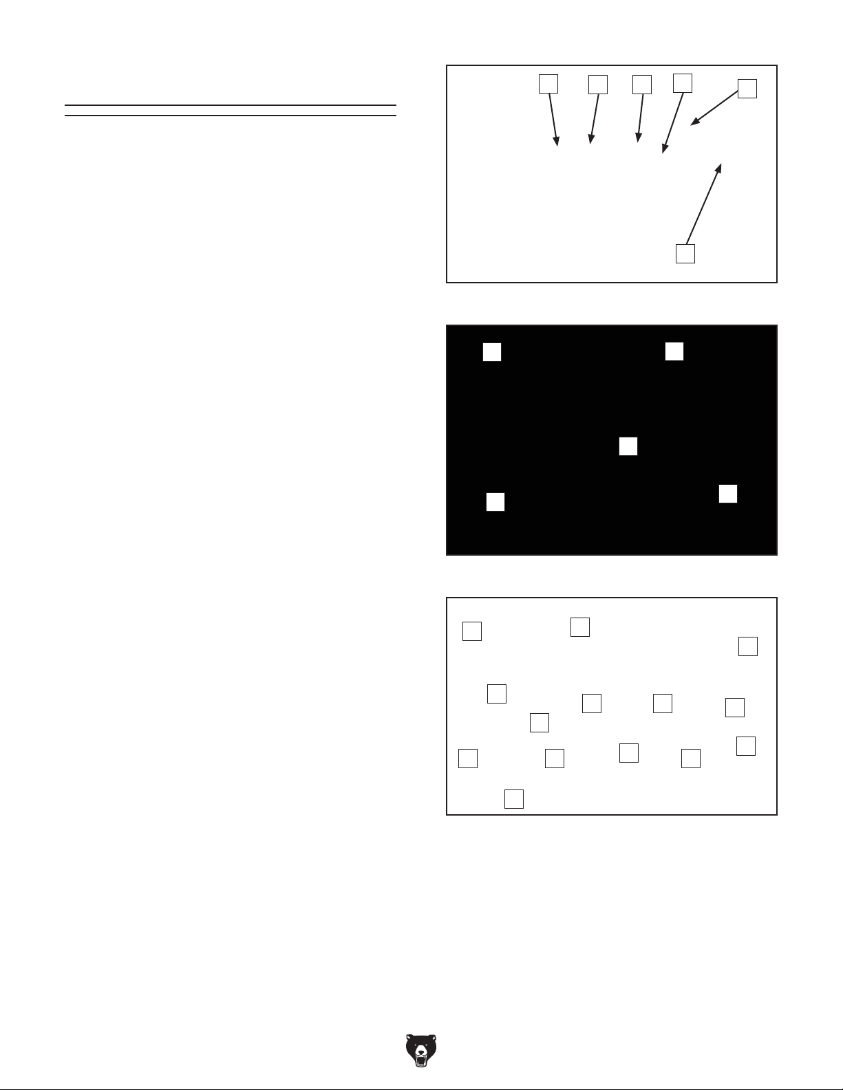
The following is a list of items shipped with your
machine. Before beginning setup, lay these items
out and inventory them.
If any non-proprietary parts are missing (e.g. a
nut or a washer), we will gladly replace them; or
for the sake of expediency, replacements can be
obtained at your local hardware store.
A
B
D
C
F
E
Mounted Components (Figure 8) Qty
A. 3-Jaw Universal Chuck 6" .......................... 1
Steady Rest ................................................ 1
B.
Follow Rest ................................................. 1
C.
Quick Change Tool Post w/Holder ............. 1
D.
Backsplash ................................................. 1
E.
Tai l s to c k ...................................................... 1
F.
G. End Gears (Installed), 20T, 45T, 80T (2),
90T (not shown) ...................................1 Ea.
Loose Components (Figure 9) Qty
H. Toolbox ........................................................1
. Faceplate 93⁄8".. ...........................................1
I
Handwheel Handles ................................... 2
J.
4-Jaw Independent Chuck 6" ..................... 1
K.
4-Jaw Chuck Wrench ................................. 1
L.
Toolbox Components (Figure 10) Qty
M. Oil Bottle ..................................................... 1
. Chuck Key .................................................. 1
N
End Gears 25T, 30T, 4 0T, 50T, 55T, 60T,
O.
63T, 65T, 70T, 75T ...................................1 Ea.
Tapered Spindle Sleeve MT#5 x MT#3 ...... 1
P.
3 -Jaw Chuck Outside Jaws ........................ 3
Q.
Hex Wrenches 2.5, 3, 4, 5, 6, 8mm... ...1 Ea.
R.
Tool Holder (One Installed) ........................ 1
S.
Cap Screws M6-1 x 14 (6 Installed) ........... 6
T.
Dead Centers MT#3 HSS Tip ..................... 2
U.
Camlock Studs (6 Installed) ....................... 6
V.
Phillips Head Screwdriver #2 ..................... 1
W.
Open-End Wrenches
X.
8/10, 12/14, 17/19mm ............................1 Ea.
Flat Head Screwdriver ¼" ........................... 1
Y.
Spider Bolts w/Nuts M8-1 x 1.25 ................ 4
Z.
Figure 8. Mounted inventory components.
H
H
K
L
Figure 9. Loose inventory components.
M
X
Z
Y
Figure 10. Toolbox inventory components.
N
T
V
W
U
I
I
J
R
S
P
O
Q
-18-
Model G0949G (Mfd. Since 01/22)
Page 21

Cabinet Components (Figure 11) Qty
AA. Left Cabinet ................................................ 1
. Front Panels ............................................... 2
AB
Right Cabinet ............................................. 1
AC.
. Panel Brackets ........................................... 2
AD
Chip Pan ..................................................... 1
AE.
Cabinet Fasteners (not shown)
AF.
—Hex Bolts M10-1.5 x 40 ........................... 6
—Flat Washers 10mm .............................. 12
—Hex Nuts M10-1.5 ................................... 6
—Cap Screws M6-1 x 14 ..........................11
—Lock Washers 6mm ................................ 8
—Flat Washers 6mm ............................... 18
—Hex Nuts M6-1 ........................................ 7
NOTICE
If you cannot find an item on this list, carefully check around/inside the machine and
packaging materials. Often, these items get
lost in packaging materials while unpacking or they are pre-installed at the factory.
AA AB
AE
Figure 11. Cabinet inventory components.
AC
AD
Model G0949G (Mfd. Since 01/22)
-19 -
Page 22
Cleanup
The unpainted surfaces of your machine are
coated with a heavy-duty rust preventative that
prevents corrosion during shipment and storage.
This rust preventative works extremely well, but it
will take a little time to clean.
Be patient and do a thorough job cleaning your
machine. The time you spend doing this now will
give you a better appreciation for the proper care
of your machine's unpainted surfaces.
There are many ways to remove this rust preventative, but the following steps work well in a wide
variety of situations. Always follow the manufacturer’s instructions with any cleaning product you
use and make sure you work in a well-ventilated
area to minimize exposure to toxic fumes.
Before cleaning, gather the following:
• Disposable rags
• Cleaner/degreaser (WD•40 works well)
• Safety glasses & disposable gloves
• Plastic paint scraper (optional)
Basic steps for removing rust preventative:
1.
2.
3.
4.
Many cleaning solvents
work in a well-ventilated
Cleanup
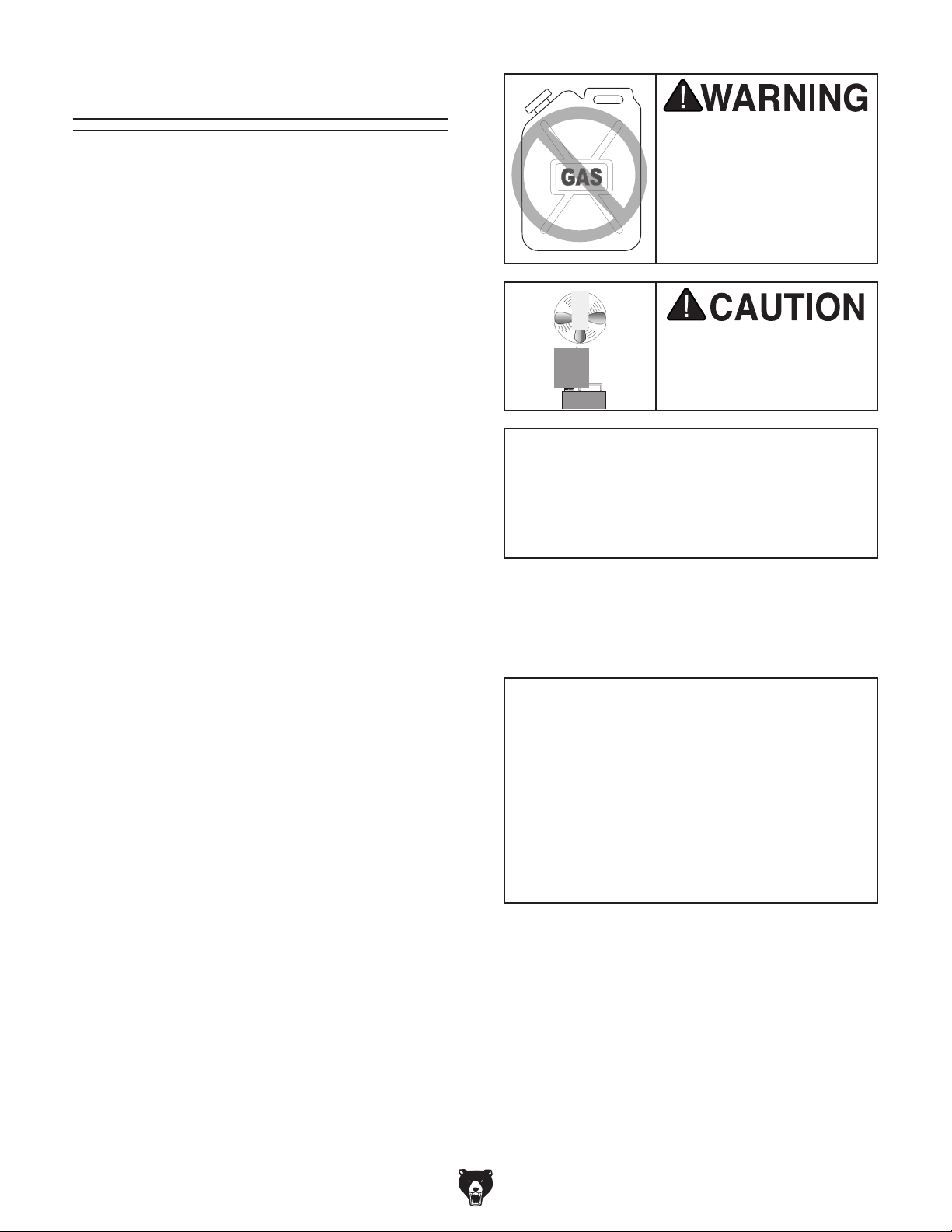
Gasoline and petroleum
products have low flash
points and can explode
or cause fire if used to
clean machinery. Avo id
using these products
to clean machinery.
Put on safety glasses.
Coat the rust preventative with a liberal
amount of cleaner/degreaser, then let it soak
for 5–10 minutes.
Wipe off the surfaces. If your cleaner/degreas-
er is effective, the rust preventative will wipe
off easily. If you have a plastic paint scraper,
scrape off as much as you can first, then wipe
off the rest with the rag.
are toxic if inhaled. Only
area.
NOTICE
Avoid harsh solvents like acetone or brake
parts cleaner that may damage painted surfaces. Always test on a small, inconspicuous location first.
T23692—Orange Power Degreaser
A great product for removing the waxy shipping grease from the non-painted parts of the
machine during clean up.
Order online at
www.grizzly.com
OR
Call 1-800-523-4777
Repeat Steps 2–3 as necessary until clean,
then coat all unpainted surfaces with a quality
metal protectant to prevent rust.
-20-
Figure 12. T23692 Orange Power Degreaser.
Model G0949G (Mfd. Since 01/22)
Page 23
Site Considerations
Weight Load
Refer to the
of your machine. Make sure that the surface upon
which the machine is placed will bear the weight
of the machine, additional equipment that may be
installed on the machine, and the heaviest workpiece that will be used. Additionally, consider the
weight of the operator and any dynamic loading
that may occur when operating the machine.
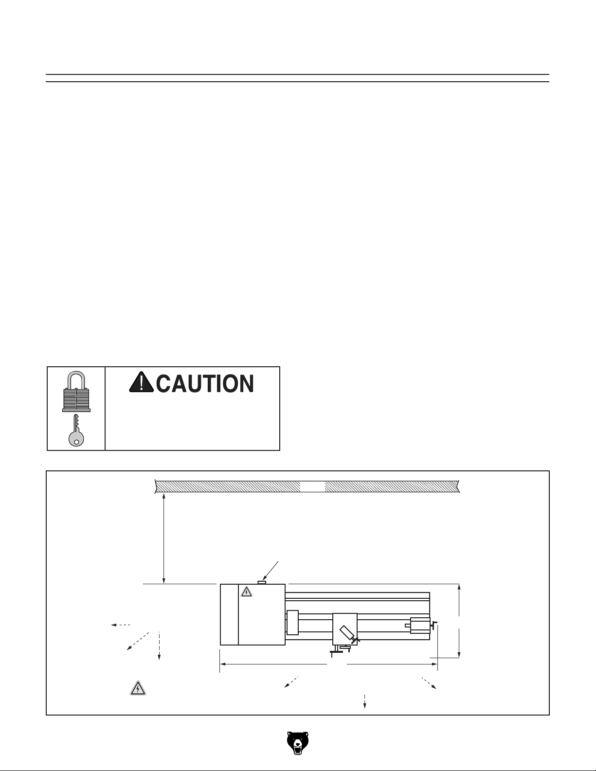
Space Allocation
Consider the largest size of workpiece that will
be processed through this machine and provide
enough space around the machine for adequate
operator material handling or the installation of
auxiliary equipment. With permanent installations,
leave enough space around the machine to open
or remove doors/covers as required by the maintenance and service described in this manual.
See below for required space allocation.
Physical Environment
Extreme conditions for this type of machinery are
Place this machine near an existing power source.
other hazards. Make sure to leave enough space
Shadows, glare, or strobe effects that may distract
or impede the operator must be eliminated.
Machine Data Sheet for the weight
Children or untrained people
may be seriously injured by
this machine. Only install in an
access restricted location.
The physical environment where the machine is
operated is important for safe operation and longevity of machine components. For best results,
operate this machine in a dry environment that is
free from excessive moisture, hazardous chemicals, airborne abrasives, or extreme conditions.
generally those where the ambient temperature
range exceeds 41°–104°F; the relative humidity
range exceeds 20%–95% (non-condensing); or
the environment is subject to vibration, shocks,
or bumps.
Electrical Installation
Make sure all power cords are protected from
traffic, material handling, moisture, chemicals, or
around machine to disconnect power supply or
apply a lockout/tagout device, if required.
Lighting
Lighting around the machine must be adequate
enough that operations can be performed safely.
Wall
Min. 30"
Model G0949G (Mfd. Since 01/22)
Keep
Endgear Access
Unobstructed
= Electrical Connection
Figure 13. Minimum working clearances.
Electrical
Cabinet
Lathe
65"
Keep Workpiece Loading
Area Unobstructed
30-1/2"
-21-
Page 24
Assembly
The machine must be fully assembled before it
can be operated. Before beginning the assembly
process, refer to
all
goes smoothly, first clean any
ered or coated in heavy-duty rust preventative (if
applicable).
Needed for Setup and gather
listed items. To ensure the assembly process
parts that are cov-
To assemble lathe:
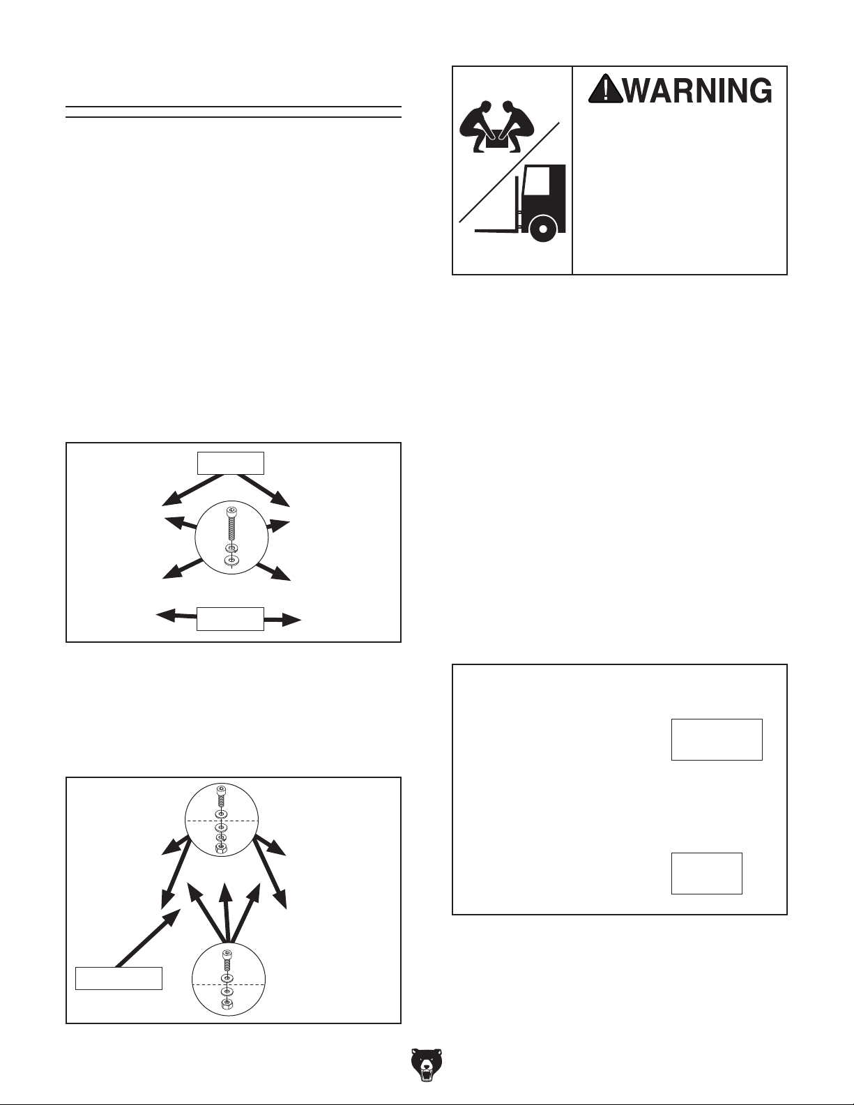
Position left and right cabinets approximately
1.
36½" apart in prepared location.
Secure panel brackets to cabinets with (4)
2.
M6-1 x 12 cap screws, 6mm lock washers,
and 6mm flat washers (see Figure 14).
Brackets
HEAVY LIF T!
Straining or crushing injury
may occur from improperly
lifting machine or some of
its parts. To reduce this risk,
get help from other people
and use a forklift (or other
lifting equipment) rated for
weight of this machine.
IMPORTANT: During the following steps, DO
NOT attempt to lift or move this lathe without
using the proper lifting equipment (such as forklift or crane) and the necessary assistance from
other people. Each piece of lifting equipment must
be rated for at least 1000 lbs. to support dynamic
loads that may be applied while lifting.
. Using a forklift, move crate to machine work
4
site location.
x 4
Cabinets
Figure 14. Panel brackets installed (rear view).
Assemble and install front panels onto panel
3.
brackets with (7) M6-1 x 14 cap screws, (14)
6mm flat washers, (7) 6mm lock washers,
and (7) M6-1 hex nuts (see Figure 15).
x 4
Remove crate top and sides, components
5.
inside crate, and blocks around machine
base.
Unbolt lathe from shipping pallet.
6.
7. Thread handles into carriage and cross slide
handwheels, as shown in Figure 16.
Cross Slide
Handle
Carriage
Handle
Front Panel
Figure 15. Front panels installed.
-22-
x 3
Figure 16. Handwheels installed.
Model G0949G (Mfd. Since 01/22)
Page 25
8.
To balance load for lifting, move tailstock and
carriage to right end of bedway, then lock
them in place.
Note: Before attempting to move carriage,
make sure carriage lock is loose, half nut is
disengaged, and feed selection lever is disengaged. Refer to Page 5 to identify these
controls.
12. Apply a 1⁄4" bead of silicone around bottom
edge of bedway pedestals.
Note: When lathe is placed on chip pan,
silicone will form a protective seal to help
prevent fluid leaking into cabinets.
Place lathe on stand while aligning mounting
13.
holes in lathe bed with holes in chip pan.
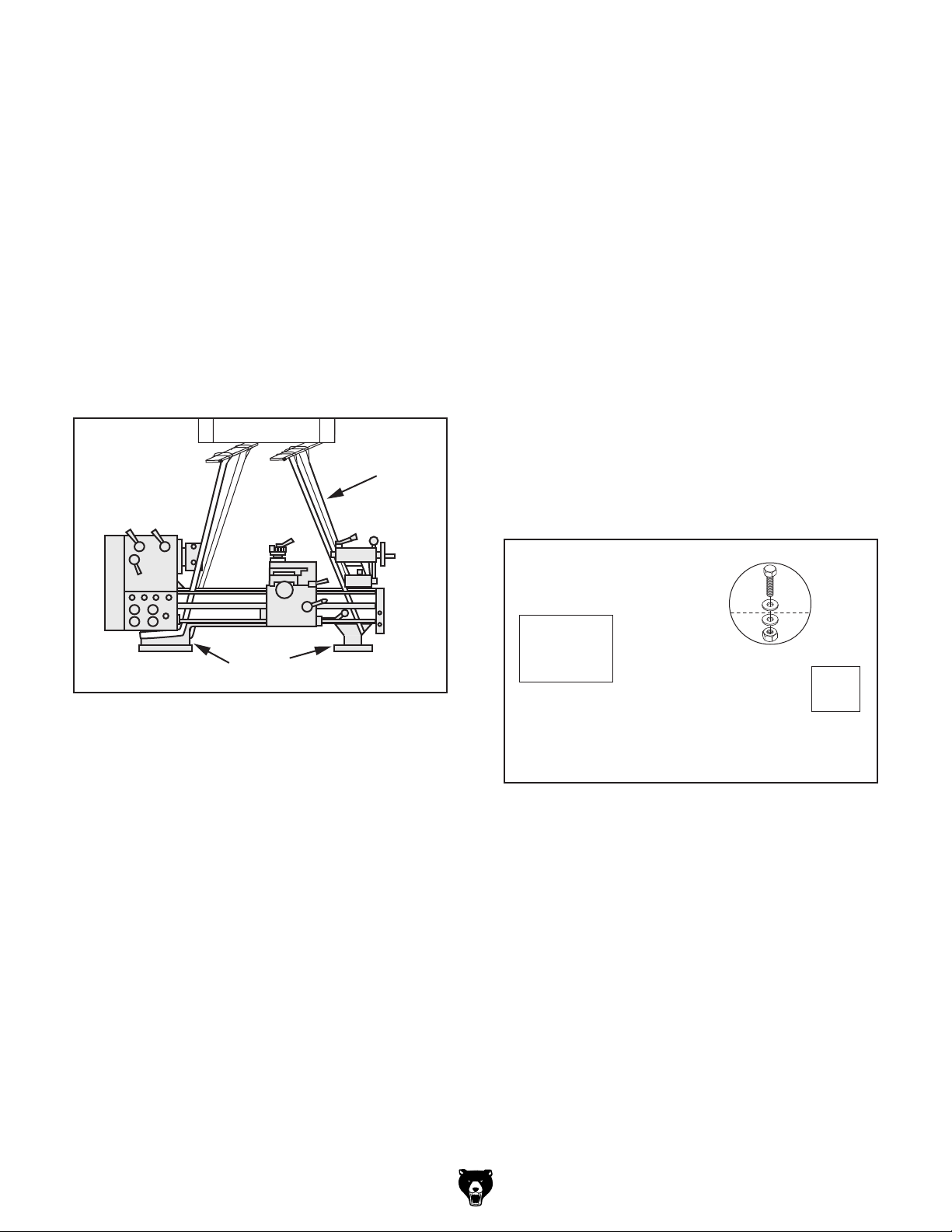
. Wrap two lifting straps (see Figure 17)
9
around bedway pedestals and route behind
feed rod and leadscrew. Then attach them
to safety hook or forks). This will keep lifting
straps away from critical components and
prevent damage to them during lifting.
Lifting Straps
Bedway
Pedestals
Figure 17. Example of lathe set up for lifting.
Remove change gear cover to gain better
14.
access to headstock base pedestal (see
Figure 18).
Attach lathe to stand and chip pan (see
15.
Figure 18) with (6) M10-1.5 x 40 hex bolts,
(12) 10mm flat washers, and (6) M10-1.5 hex
nuts. Do not fully tighten fasteners until lathe
has been leveled.
Note: Remove drawers for easier access to
left side mounting hardware.
x 2
Headstock
Base
Pedestal
Chip
Pan
Position chip pan on top of cabinet stands
10.
and align six mounting holes with those on
cabinet stands.
Slowly raise lathe from pallet and have
11.
another person hold lathe with a lifting strap
to prevent it from swinging.
Model G0949G (Mfd. Since 01/22)
Figure 18. Lathe attached to stand and chip pan
(left side mounting hardware shown).
16.
Level machine as instructed in Leveling on
Page 24, then proceed to Step 17.
. Fully tighten fasteners installed in Step 15.
17
. Install change gear cover.
18
-23-
Page 26
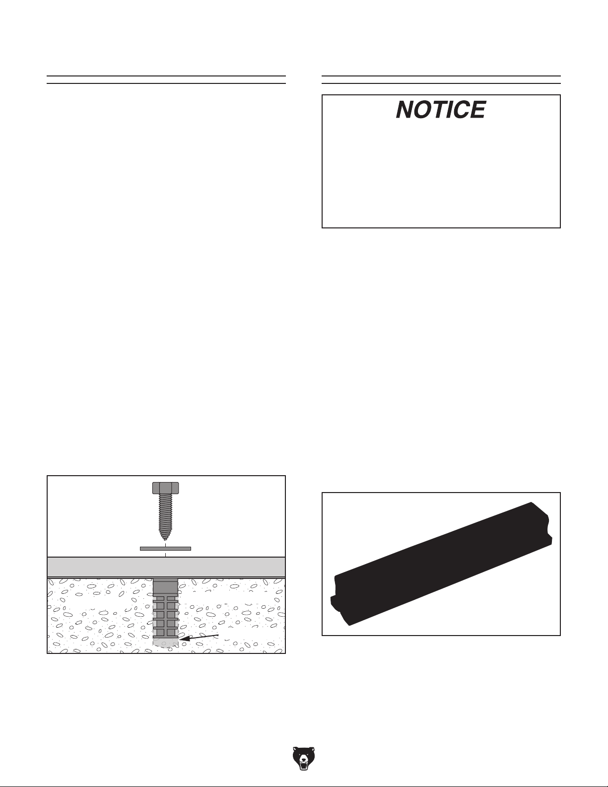
Anchoring machinery to the floor prevents tipping
or shifting and reduces vibration that may occur
during operation, resulting in a machine that runs
slightly quieter and feels more solid.
If the machine will be installed in a commercial or
workplace setting, or if it is permanently connected (hardwired) to the power supply, local codes
may require that it be anchored to the floor.
If not required by any local codes, fastening the
machine to the floor is an optional step. If you
choose not to do this with your machine, we recommend placing it on machine mounts, as these
provide an easy method for leveling and they have
vibration-absorbing pads.
Anchoring to Floor
Lag shield anchors with lag screws (see below)
are a popular way to anchor machinery to a concrete floor, because the anchors sit flush with the
floor surface, making it easy to unbolt and move
the machine later, if needed. However, anytime
local codes apply, you MUST follow the anchoring
methodology specified by the code.
Number of Mounting Holes ............................ 8
Diameter of Mounting Hardware
Anchoring to Concrete Floors
.................1⁄2"
Leveling
For accurate turning results and to prevent
warping the cast iron bed and ways, the
lathe bedways MUST be leveled from sideto-side and from front-to-back on both ends.
Recheck the bedways 24 hours after
installation, two weeks after that, and then
annually to make sure they remain level.
Leveling machinery helps precision components,
such as bedways, remain straight and flat during
the lifespan of the machine. Components on a
machine that is not level may slowly twist due to
the dynamic loads placed on the machine during
operation.
If needed, use metal shims between the lathe bed
and chip pan when leveling the machine.
Machine Base
Concrete
Figure 19. Popular method for anchoring
machinery to a concrete floor.
Lag Screw
Flat Washer
Lag Shield Anchor
Drilled Hole
For best results, use a precision level that is at
least 12" long and sensitive enough to show a
distinct movement when a 0.003" shim (approximately the thickness of one sheet of standard
newspaper) is placed under one end of the level.
See the figure below for an example of a high
precision level offered by Grizzly.
Figure 20. Model H2683 precision level.
-24-
Model G0949G (Mfd. Since 01/22)
Page 27
DO NOT start machine until all preceding
setup instructions have been performed.
Operating an improperly set up machine
Serious injury or death can result from
Once assembly is complete, test run the machine
to ensure it is properly connected to power and
safety components are functioning correctly.
If you find an unusual problem during the test run,
immediately stop the machine, disconnect it from
power, and fix the problem BEFORE operating the
machine again. The
table in the
SERVICE section of this manual can help.
Lubricating Lathe
GEARBOXES MUST
BE FILLED WITH OIL!
Test Run
MACHINE MAY NOT BE
SHIPPED WITH OIL!
Requires Oil
Before Operation
or Warranty Will
Be Void.
The headstock, gearbox, and apron oil reservoirs
must have the proper amount of oil in them before
lathe can be operated.
Damage caused to bearings and gears from
running lathe without oil in reservoirs will not be
covered under warranty. Refer to Lubrication
section, beginning on Page 60, for checking and
adding oil.
In addition to reservoirs, we also recommend that
you lubricate all other points on machine at this
time. To do this, follow steps provided in maintenance schedule on Page 59.
Note: If this lathe was shipped with oil in the res-
ervoirs, do not change that oil until after the Test
Run and Spindle Break-In procedures.
Troubleshooting
The test run consists of verifying the following:
1) The motor powers up and runs correctly, and
2) the emergency stop button safety feature
works correctly.
using this machine BEFORE understanding
its controls and related safety information.
DO NOT operate, or allow others to operate,
machine until the information is understood.
may result in malfunction or unexpected results that can lead to serious injury,
death, or machine/property damage.
Model G0949G (Mfd. Since 01/22)
-25-
Page 28
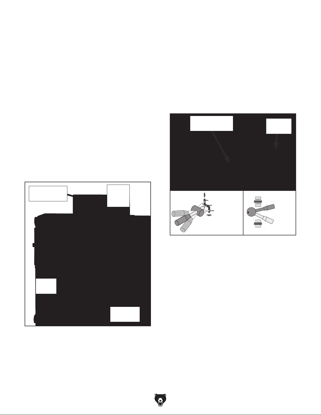
To test run machine:
Cross Slide
Disengaged
Feed Selection
Lever
Carriage
1. Clear away all tools and objects used during
assembly, lubrication, and preparation.
Make sure that chuck and jaws, if installed,
2.
are secure (refer to Chuck Installation on
Page 31).
Note: If chuck is not installed on lathe, you do
not need to install one for this test.
Verify master power switch (see Figure 21) is
3.
in OFF position.
Press E-Stop button (see Figure 21).
4.
Move FWD/REV switch to "0" position (see
5.
Figure 21).
Rotate spindle speed dial all the way counter-
6.
clockwise (see Figure 21).
Note: In the next step, you may need to rock the
chuck back and forth as you make the adjustments, so that the gears will mesh together.
To ensure carriage components do not unex-
7.
pectedly move during the following steps,
disengage half nut lever and feed selection lever (see Figure 22). Rotate carriage
and cross slide handwheels back and forth
while moving levers to verify they are disengaged. When disengaged, handwheels will
turn easily.
Feed Selection
Lever
Half Nut
Half Nut
Lever
Lever
Master Power
Switch
Spindle
Speed
Dial
E-Stop
Button
FWD/REV
Switch
Figure 21. Headstock and gearbox controls.
Disengaged
Half Nut
Lever
Engaged
Figure 22. Disengaging carriage components.
-26-
Model G0949G (Mfd. Since 01/22)
Page 29
8. Connect machine to power supply.
Press E-Stop button to turn machine OFF.
14.
Turn master power switch to ON position,
9.
and reset E-Stop button by twisting it clockwise until it pops out.
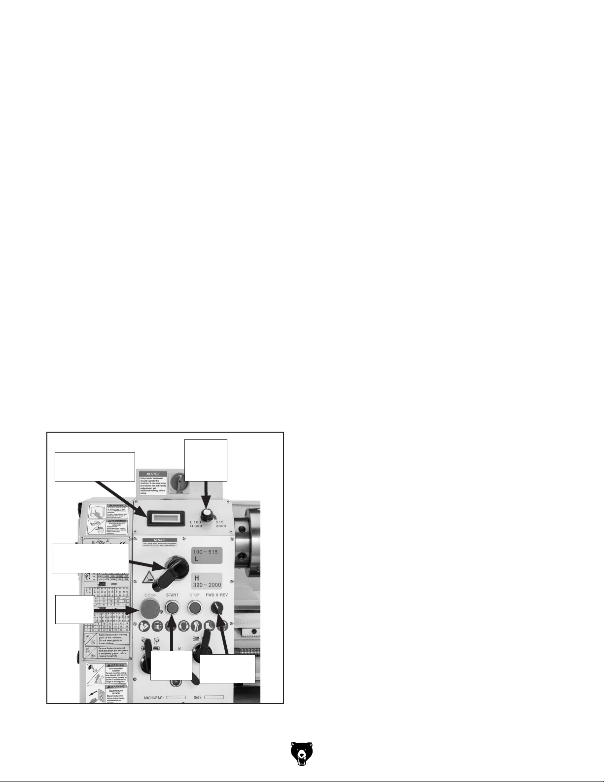
Move spindle speed range lever to Low (L)
10.
position (see Figure 23).
Move FWD/REV switch to FWD position (see
11.
Figure 23).
Rotate spindle speed dial until spindle
12.
speed digital readout shows 150 RPM
(see Figure 23).
Push START button (see Figure 23). Chuck
13.
should turn counterclockwise and down
toward the front of the lathe.
When operating correctly, the machine will
—
run smoothly with little or no vibration or
rubbing noises.
— Investigate and correct strange or unusual
noises or vibrations before operating the
machine further. Always disconnect the
machine from power when investigating or
correcting potential problems.
WITHOUT resetting E-Stop button, try to start
15.
machine by pressing START button. The
machine should not start.
If spindle rotation does not start, E-Stop
—
safety feature is working correctly.
— If spindle rotation does start, immediately
turn machine OFF and disconnect power.
The E-Stop button safety feature is NOT
working properly and must be replaced
before further using the machine.
Reset E-Stop button.
16.
Push START button to verify machine will
17.
start.
Push STOP button to verify machine stops.
18.
Congratulations! The test run is complete. Perform
Spindle Break-In procedure on Page 28.
Spindle
Spindle Speed
Digital Readout
Spindle Speed
Range Lever
E-Stop
Button
START
Button
Figure 23. Spindle speed and rotation controls.
Speed
Dial
FWD/REV
Switch
Model G0949G (Mfd. Since 01/22)
-27-
Page 30

Spindle Break-In
Before subjecting the spindle to operational loads,
it is essential to complete the break-in process.
This helps maximize the life of spindle bearings
and other precision components by thoroughly
lubricating them before placing them under load.
After spindle break-in is complete, we recommend
changing headstock and gearbox oil to remove
any metal particles or debris that are present from
the assembly and break-in process.
The break-in must be performed in succession
with the
manual, as the steps in that procedure prepare
the lathe controls for the break-in process.
Test Ru n procedure described in this
DO NOT perform this procedure independently of the Test Run section. The lathe
could be seriously damaged if the controls
are set differently than instructed in that
section.
To perform spindle break-in:
Run lathe at spindle speeds of 500, 1300,
8.
and 1800 RPM. Run for a minimum of 5 minutes at each speed in each direction of rotation.
Press E-Stop button and DISCONNECT
9.
MACHINE FROM POWER!
Change headstock and gearbox oil before
10.
operating machine further to ensure full
machine warranty (refer to Lubrication on
Page 60).
Recommended
Adjustments
The following adjustments have been made at the
factory. However, because of the many variables
involved with shipping, we recommend you verify
these adjustments to ensure the best results:
Factory adjustments that should be verified:
• Tailstock Alignment (Page 39).
• Backlash Adjustment (Page 69).
• Gib Adjustment (Page 70).
Successfully complete Test Run procedure
1.
beginning on Page 25.
Set spindle speed range lever to Low (L)
2.
range, select forward spindle rotation, then
turn machine ON and run spindle at 150 RPM
for 10 minutes.
Stop spindle rotation and wait until spindle
3.
has come to a complete stop.
Select reverse spindle rotation and run spin-
4.
dle at 150 RPM for 10 minutes.
Repeat Steps 2–4 at 400 RPM for 5 minutes.
5.
Set FWD/REV switch to "0".
6.
7. Set spindle speed range lever to High (H).
-28-
Model G0949G (Mfd. Since 01/22)
Page 31
SECTION 4: OPERATIONS
The purpose of this overview is to provide the novice machine operator with a basic understanding
of how the machine is used during operation, so
the
discussed later
in this manual
Due to the generic nature of this overview, it is
not intended to be an instructional guide. To learn
more about specific operations,
manual,
training from experienced
machine operators
outside of this manual by reading "how-to" books,
trade magazines, or websites.
To reduce your risk of
serious injury, read this
entire manual BEFORE
Operation Overview
machine controls/components
are easier to understand.
To complete a typical operation, the operator
does the following:
Puts on safety glasses and a face shield, rolls
1.
up sleeves, removes jewelry, and secures
any clothing or hair that could get entangled
in moving parts.
Examines workpiece to make sure it is suit-
2.
able for turning, then securely mounts it in
lathe.
read this entire
seek additional
, and do additional research
using machine.
To reduce risk of eye or face injury from
flying chips, always wear approved safety
glasses and face shield when operating this
machine.
Installs tooling, aligns it with the workpiece,
3.
then backs it away to establish a safe startup
clearance.
Removes all setup tools from lathe.
4.
5. Checks for safe clearances by rotating
workpiece by hand at least one full revolution.
Moves slides to where they will be used dur-
6.
ing operation.
7. Sets correct spindle speed range for
operation.
If using power feed, selects proper feed rate
8.
for operation.
Presses E-Stop button, and connects
9.
machine to power supply.
Resets E-Stop button, and rotates master
10.
power switch to ON position.
If you are not experienced with this type
of machine, WE STRONGLY RECOMMEND
that you seek additional training outside of
this manual. Read books/magazines or get
formal training before beginning any projects. Regardless of the content in this section, Grizzly Industrial will not be held liable
for accidents caused by lack of training.
Model G0949G (Mfd. Since 01/22)
Rotates spindle speed dial to correct speed
11.
for operation, then presses START button.
Uses carriage handwheels or power feed
12.
options to move tooling into workpiece for
operation.
13. When finished cutting, presses STOP button,
waits for the spindle rotation to stop, and then
removes the workpiece.
-29-
Page 32
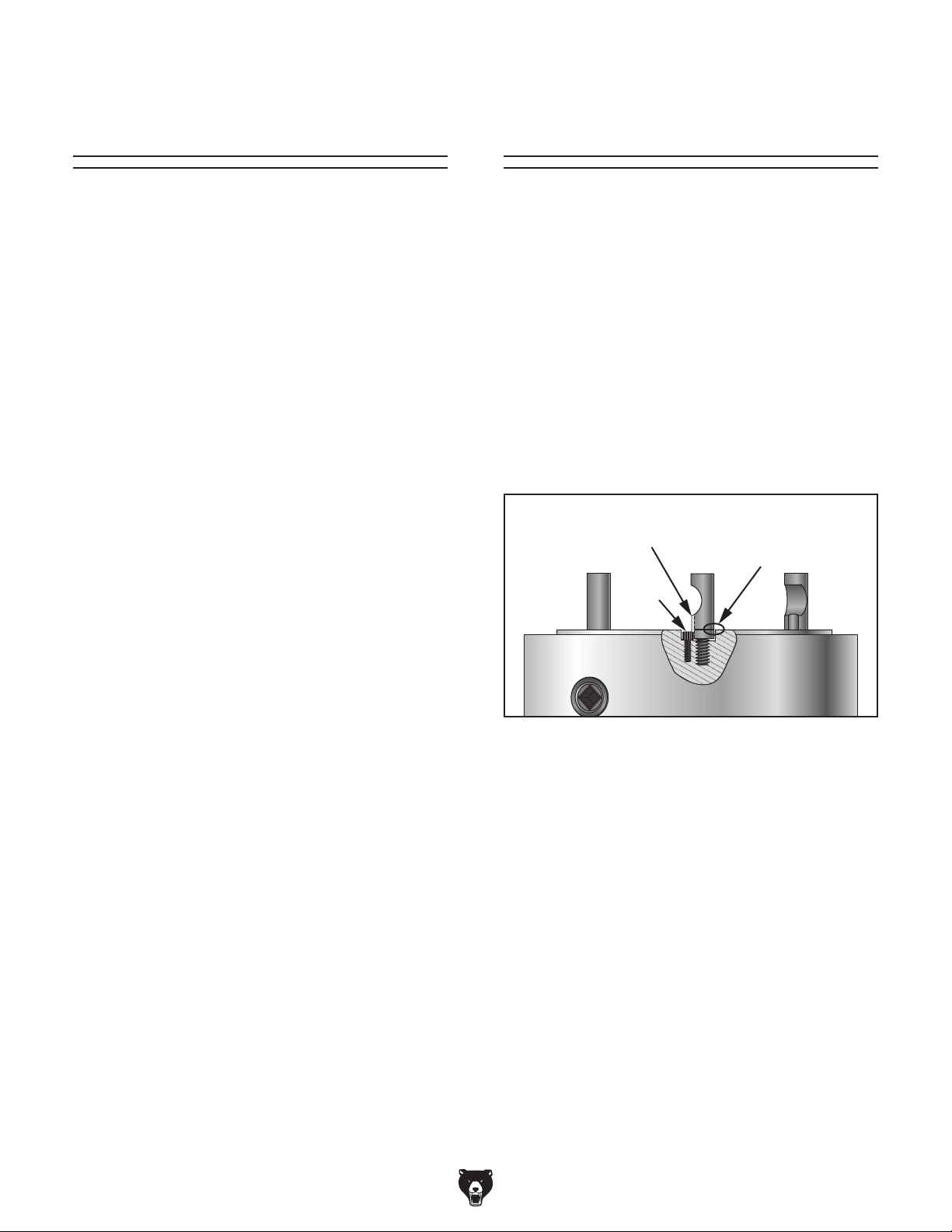
Chuck & Faceplate
This lathe is equipped with a D1-type spindle
nose. This type of spindle uses camlocks that are
adjusted with a chuck key to securely mount a
chuck or faceplate with repeatable precision and
ease.
This lathe ships with the 3-jaw chuck installed.
This is a scroll-type chuck where all three jaws
move in unison when the chuck key is used.
The included 4-jaw chuck features independent
jaws, which are used for square or unevenlyshaped stock, and to mount work that needs to be
adjusted to near-zero total indicated runout.
The included faceplate has slots for T-bolts that
hold standard or custom clamping hardware. With
the correct clamping hardware, a faceplate offers
a wide range of uses, including machining nonconcentric workpieces, straight turning between
centers, off-center turning, and boring.
This lathe ships with the 3-jaw chuck installed.
This is a scroll-type chuck where all three jaws
move in unison when the chuck key is used.
The included 4-jaw chuck features independent
jaws, which are used for square or unevenlyshaped stock, and to mount work that needs to be
To install camlock studs:
1.
2.
or
positioned over hole.
Follow this procedure to install camlock studs in
chuck
can be
mount
Note:
kip this section if camlock studs are
already installed.
3. Install a cap screw in hole next to each stud.
It is normal for studs to have a small
amount of play or looseness after installing
and tightening the cap screws.
Camlock Stud
Mounting
Installation
s, faceplates, or drive plates so they
ed to the spindle.
S
Lightly oil threads of each stud.
Thread studs until datum line is flush with (
just above) surface and alignment groove is
Alignment
Groove
Cap
Screw
Datum Line
Flush with
Surface
-30-
Figure 24. Camlock stud installation.
These cap screws prevent studs from rotating so they properly engage with camlock
during installation.
Note:
Model G0949G (Mfd. Since 01/22)
Page 33
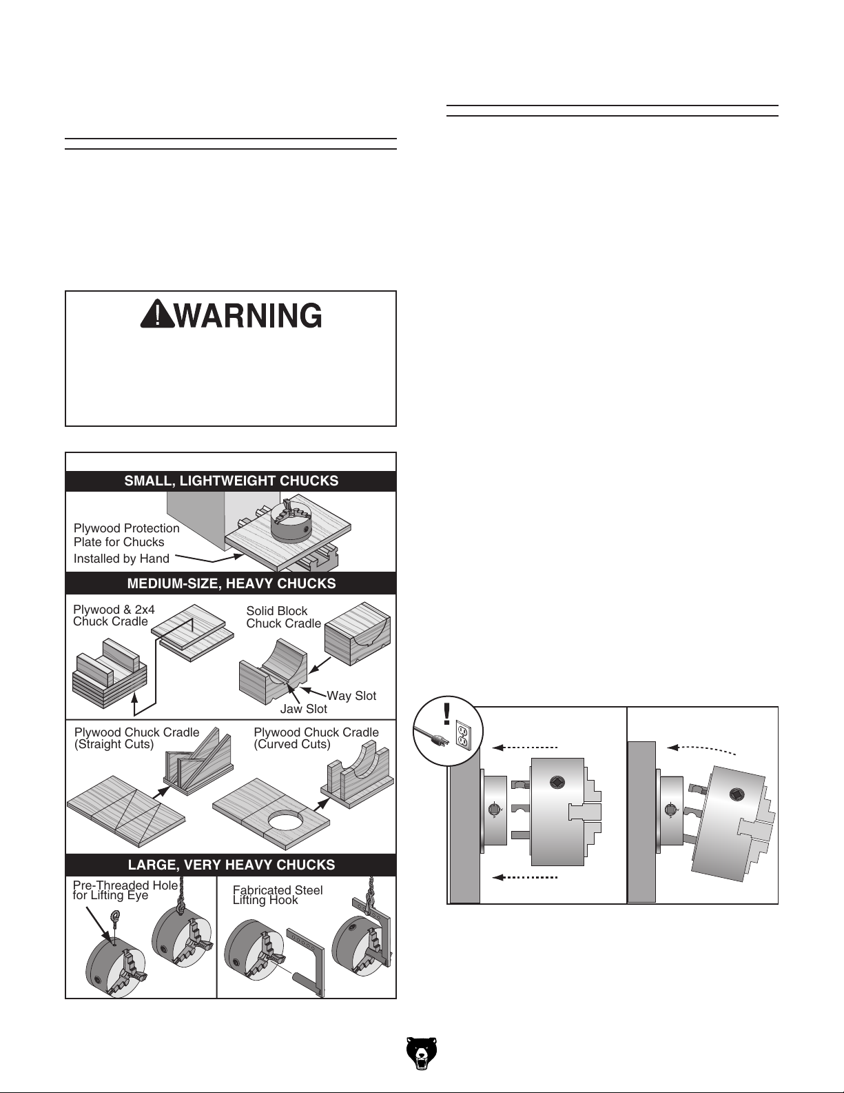
Chuck Safety &
Because chucks are heavy and often awkward
to hold, some kind of lifting, support, or protective device should be used during installation or
removal. The weight and size of the chuck will
determine the appropriate device to use (refer to
the following figure for examples).
lways use
Pre-Threaded Hole
for Lifting Eye
Way Slot
Jaw Slot
Plywood & 2x4
Chuck Cradle
Plywood Chuck Cradle
(Straight Cuts)
Plywood Chuck Cradle
(Curved Cuts)
Fabricated Steel
Lifting Hook
Solid Block
Chuck Cradle
Plywood Protection
Plate for Chucks
Installed by Hand
MEDIUM-SIZE, HEAVY CHUCKS
LARGE, VERY HEAVY CHUCKS
SMALL, LIGHTWEIGHT CHUCKS
To ensure accurate work, it is extremely important
to make sure the spindle nose and chuck mating
surfaces/tapers are clean. Even a small amount of
lint or debris can affect accuracy.
The chuck is properly installed when all camlocks
are tight, the spindle and chuck tapers firmly
lock together, and the back of the chuck is firmly
seated against the face of the spindle all the way
around—without any gaps.
To install chuck:
1.
2.
Chuck
3.
4. Install chuck by inserting camlock studs
pivoting them in from an angle or rotating the
Support Devices
Accidentally dropping a chuck can cause
amputation, crushing injuries, or property
damage. To reduce this risk, a
some kind of lifting, support, or protective
device during installation or removal.
Chuck Installation
DISCONNECT MACHINE FROM POWER!
Use appropriate lifting, support, or protective
device to protect ways and support chuck
during installation process (refer to
Safety & Support Devices).
Clean and lightly oil camlock studs, then thor-
oughly clean mating surfaces of spindle and
chuck.
straight into spindle cam holes.
IMPORTANT: Avoid inserting the studs by
spindle. This can damage studs or spindle
INCORRECTCORRECT
Figure 25. Examples of common devices used
during chuck installation and removal.
Model G0949G (Mfd. Since 01/22)
Figure 26. Inserting camlock studs into spindle
cam holes.
-31-
Page 34
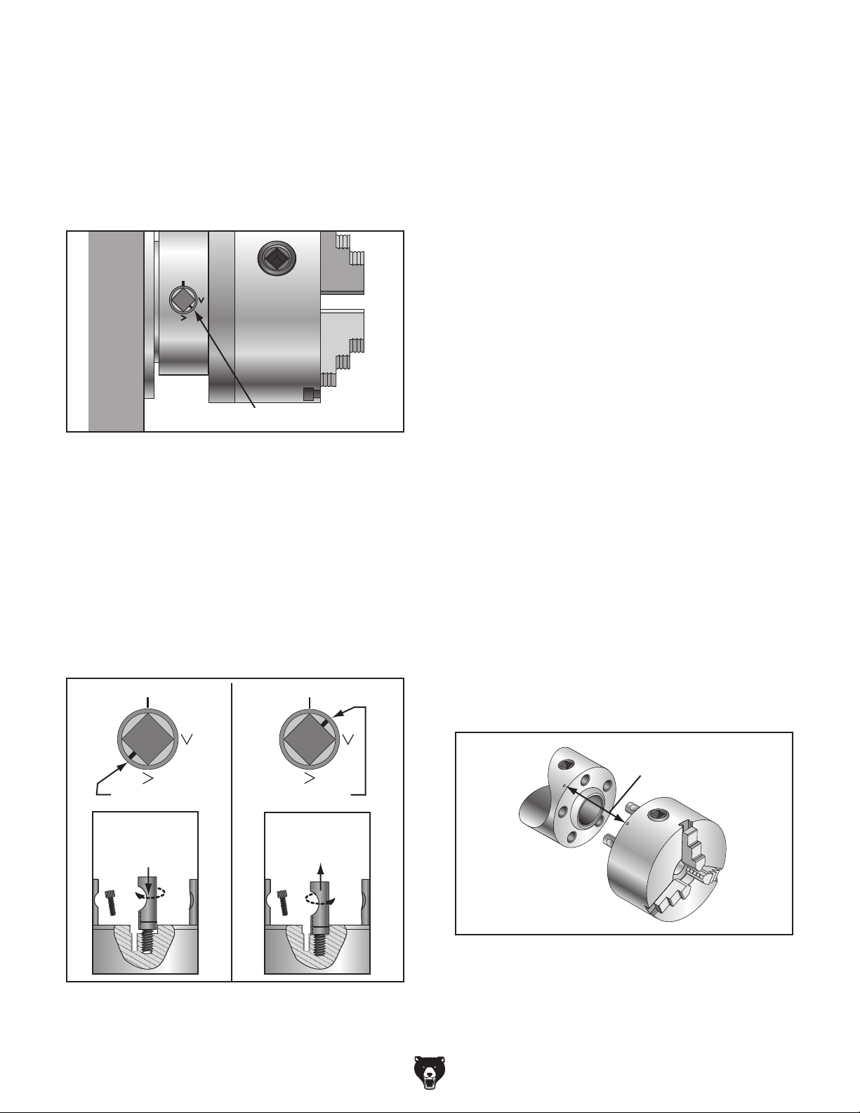
5. Incrementally tighten camlocks in criss-cross
or star pattern to ensure that chuck seats
6.
between the
in
following figure.
— If cam line is NOT between "V" marks when
chuck.
Lightly stamp registration marks across the mating
seams of chuck components
help you re-install the chuck in the same position
after removal, which ensures consistent chuck
balance and turning results, and allows the
same camlocks and studs to operate together for
consistent locking and unlocking.
7. Verify that chuck fits spindle properly by
checking for any gaps between mating
If problem persists, contact our Tech
8.
— If tapers released easily with little interven-
tion, they are not seated together firmly as
lem persists, contact our Tech Support.
evenly against spindle.
surfaces.
When chuck is fully seated and all camlocks
are tight, verify that cam line is
two "V" marks on spindle nose, as shown
Cam Line Between "V"s
Figure 27. Cam line positioned between the "V"
marks after the camlocks are fully tightened.
camlock is tight, stud may be installed at
incorrect height. To fix this, adjust stud
height as shown in following figure. Make
sure to re-install stud cap screw afterward.
— If there is not a gap, proceed to Step 8.
— If there is a gap, remove chuck, re-clean
mating surfaces carefully, and re-install.
Support.
Verify that chuck/spindle tapers are seat-
ed firmly together by removing chuck, per
Chuck Removal instructions on following
page, and pay close attention to how easily
tapers release.
— If it was necessary to bump chuck or use
a mallet to release tapers, then they are
seating together properly.
required. Remove chuck, re-clean mating
surfaces carefully, and re-install. If prob-
Registration Marks
— If adjusting stud height does not correct
problem, try swapping stud positions on
-32-
INCORRECT INCORRECT
Stud Too High:
Turn In
One-Turn
Figure 28. Correcting an improperly installed
stud.
Stud Too Low:
Turn Out
One-Turn
. These marks will
Spindle & Chuck
Camlock
Spindle
Figure 29. Registration mark locations.
Model G0949G (Mfd. Since 01/22)
Registration Marks
Page 35
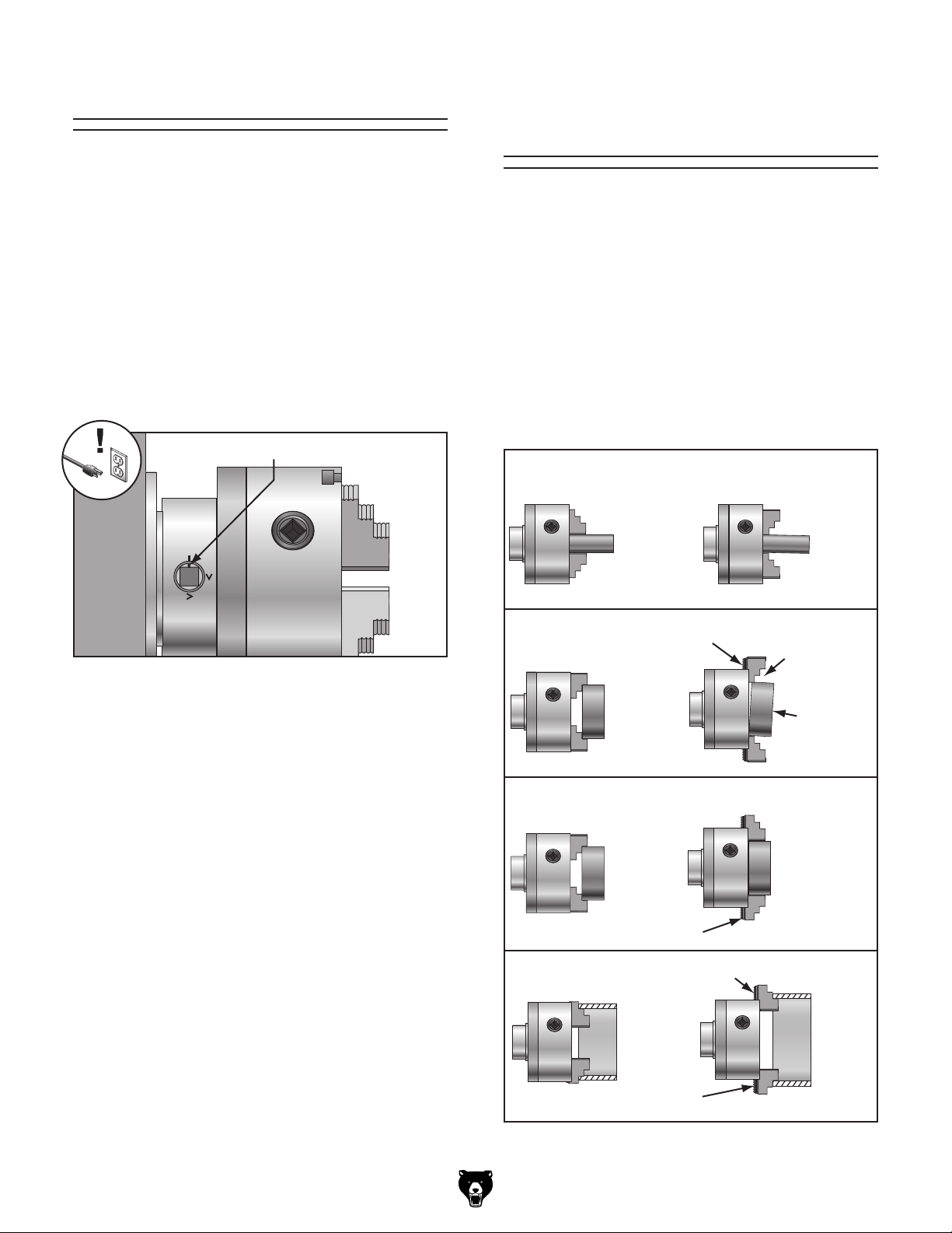
Chuck Removal
To remove chuck:
Chuck Safety & Support Devices
This 3-jaw, scroll-type chuck has an internal scrollgear
djusted
with the chuck key
cylindrical
parts on-center with the axis of spindle rotation
and can be
at high speeds if the workpiece
is properly clamped and balanced.
IMPORTANT: Never mix jaw types or
positions
to accommodate an odd-shaped workpiece.
T
may throw
the workpiece
chuck or a faceplate.
Tip: Camlocks can become very tight. A
cheater pipe may be used as a last resort to
add leverage when loosening. After loosening, you may need to wiggle the chuck key in
4.
5.
ing motion to carefully slide studs out of cam
rotate it approximately 60° and tap it
spindle are properly aligned for removal.
1. DISCONNECT MACHINE FROM POWER!
2. Use appropriate lifting, support, or protective
device to protect ways and support chuck
(refer to
section for more details).
Scroll Chuck
Clamping
that moves all jaws in unison when a
. This chuck holds
rotated
3. Loosen camlocks by turning key counter-
clockwise until each cam line is aligned with
its corresponding spindle mark, as shown
Cam Line and Spindle Mark Aligned
Figure 30. Camlock is fully loosened when the Camlock is fully loosened when the
cam line is aligned with the spindle mark.cam line is aligned with the spindle mark.
the camlock to fully disengage the stud.
Using dead blow hammer or other soft mal-
let, lightly tap around outer circumference of
chuck body to loosen it from spindle.
Remove chuck from spindle, using light rock-
he chuck will spin out of balance and
! Instead, use an independent jaw
Safer Inside
Jaw Use
CORRECT
Safer Outside
Jaw Use
CORRECT
Safer Outside
Jaw Use
CORRECT
Bar Stock
Unsafe Jaw Position and
Poor Scroll Gear Engagement
Shallow
Bar Stock
Shallow
Bar Stock
Unsafe Jaw
Position
Insufficient
Jaw Clamping
INCORRECT
INCORRECT
Unsafe Inside
Jaw Use
Poor Scroll
Gear
Engagement
INCORRECT
Unstable
Workpiece
Poor Grip
Unstable
Workpiece
holes.
— If chuck does not immediately come off,
again. Make sure all marks on cams and
Model G0949G (Mfd. Since 01/22)
Safer Inside
Jaw Use
CORRECT
Cylinder
Poor Scroll
Gear Engagement
Unsafe Jaw Position
INCORRECT
Figure 31. Jaw selection and workpiece holding.
-33-
Page 36
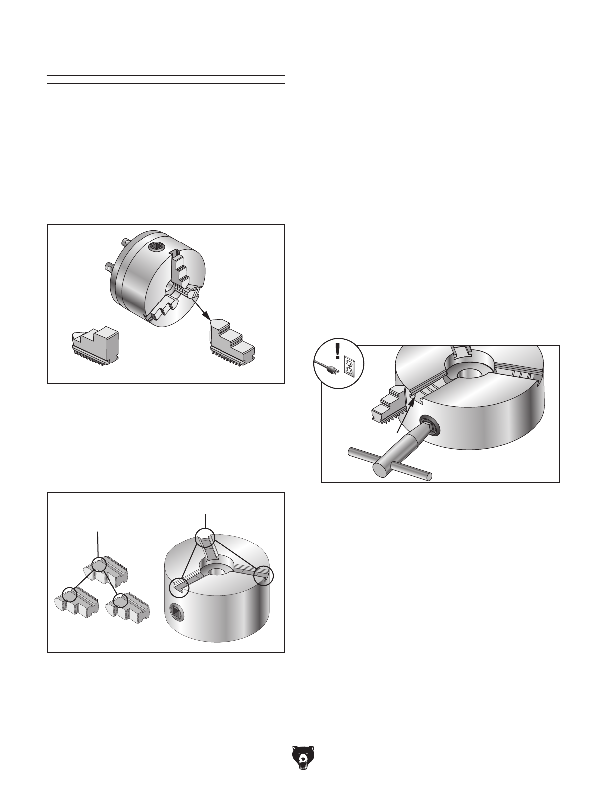
Changing Jaw Set
The 3-jaw scroll chuck included with the lathe
features inside and outside
sets
move in unison to
center a concentric workpiece.
When installing the jaws
sure they are installed correctly. Incorrect installation will result in jaws that do not converge evenly
and are unable to securely clamp a workpiece.
To change jaw set:
1.
2.
(refer
subsec-
3.
4.
5.
n safe place free
6.
of outer scroll-gear lead thread about to enter
a jaw guide (see below).
7. Insert jaw #1 into jaw guide and hold jaw
8. Rotate chuck key clockwise one turn to
engage tip of scroll-gear lead thread into jaw.
9
and
gear lead thread during its first rotation.
Jaws are numbered from 1–3 (see Figure below).
The number is typically stamped on the side or
bottom. Jaws are designed to be installed counterclockwise in numerical order in the jaw guides,
so they will hold a concentric workpiece evenly.
DISCONNECT MACHINE FROM POWER!
hardened steel jaw
(see Figure below), which
, it is important to make
Use appropriate device to protect ways
to Installation & Removal Device
tion).
Insert chuck key and turn it counterclockwise
to back jaws out and remove them individually in descending order (i.e., 3, 2, 1).
Use mineral spirits to clean debris and grime
from jaws and chuck jaw guides.
Apply thin coat of NLGI #2 grease to surfaces
of removed jaw set. Store i
from moisture and abrasives.
Rotate chuck key clockwise until you see tip
Inside SetOutside Set
Figure 32. Chuck and jaw selection.
Jaw Guides
Jaw Numbers
1
2
3
Figure 33. Jaw guides and jaw numbers.
-34-
1
Lead Thread
Figure 34. Lead thread on scroll gear.
against scroll-gear.
Pull jaw; it should be locked into jaw guide.
. Install remaining jaws in numerical order, in
same manner. The jaws should converge
evenly at center of chuck.
— If jaws do not converge evenly, remove
them. Re-install jaws sequentially 1–3,
make sure each one engages with scroll-
Model G0949G (Mfd. Since 01/22)
Page 37
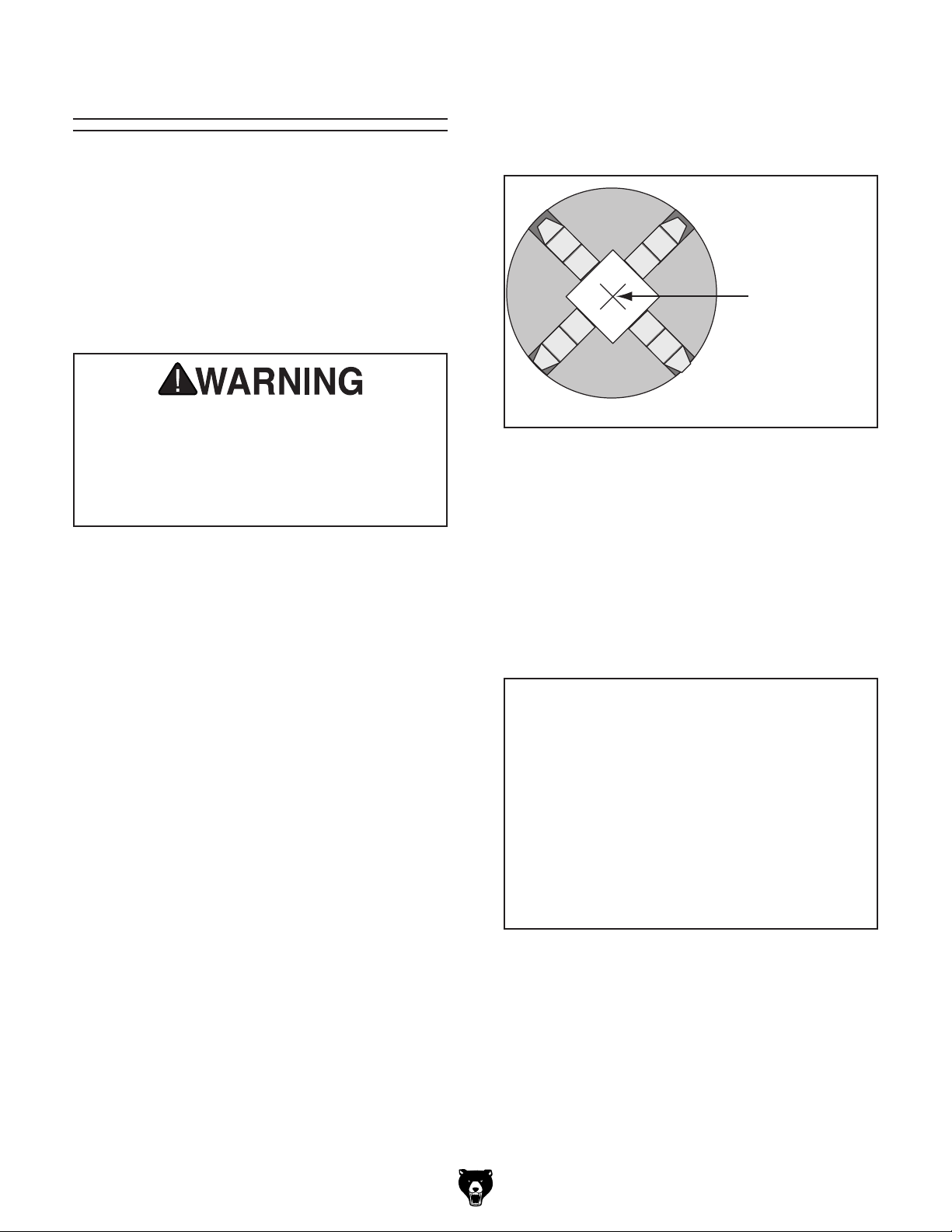
4-Jaw Chuck
Refer to the Chuck Installation or Chuck
Removal
removing the 4-jaw chuck.
The 4-jaw chuck features independently adjustable jaws for holding non-concentric or off-center
workpieces. Each jaw can be independently
removed from the chuck body and reversed for a
wide range of work-holding versatility.
Because of dynamic forces involved in
Mounting Workpiece
1.
2.
Chuck Safety & Support Devices
3.
4.
device, position workpiece so it is centered in
chuck.
5. Tighten each jaw in small increments. After
tightening first jaw, continue tightening
similar to sequential order shown below.
6. After workpiece is secured by jaws, use dial
indicator to make sure workpiece is centered
— If workpiece is not correctly centered,
make fine adjustments by slightly loosening
workpiece is correctly positioned (see
below for an example).
sections for instructions on installing or
remaining jaws in an opposing sequence,
machining a non-concentric or off-center
workpiece, always use a low spindle speed
to reduce risk of workpiece coming loose
and being thrown from lathe, which could
cause death or serious personal injury.
DISCONNECT MACHINE FROM POWER!
Use an appropriate device to protect ways
(refer to
section for more details).
1
3
Workpiece
Center Point
4
Figure 35. 4-jaw chuck tightening sequence.
in chuck.
one jaw and tightening opposing jaw until
2
Use chuck key to open each jaw so workpiece will fit into spindle opening and lay flat
against chuck face and jaw steps.
With help from another person or a holding
Model G0949G (Mfd. Since 01/22)
Figure 36. Example of a non-cylindrical
workpiece mounted on a 4-jaw chuck.
-35-
Page 38
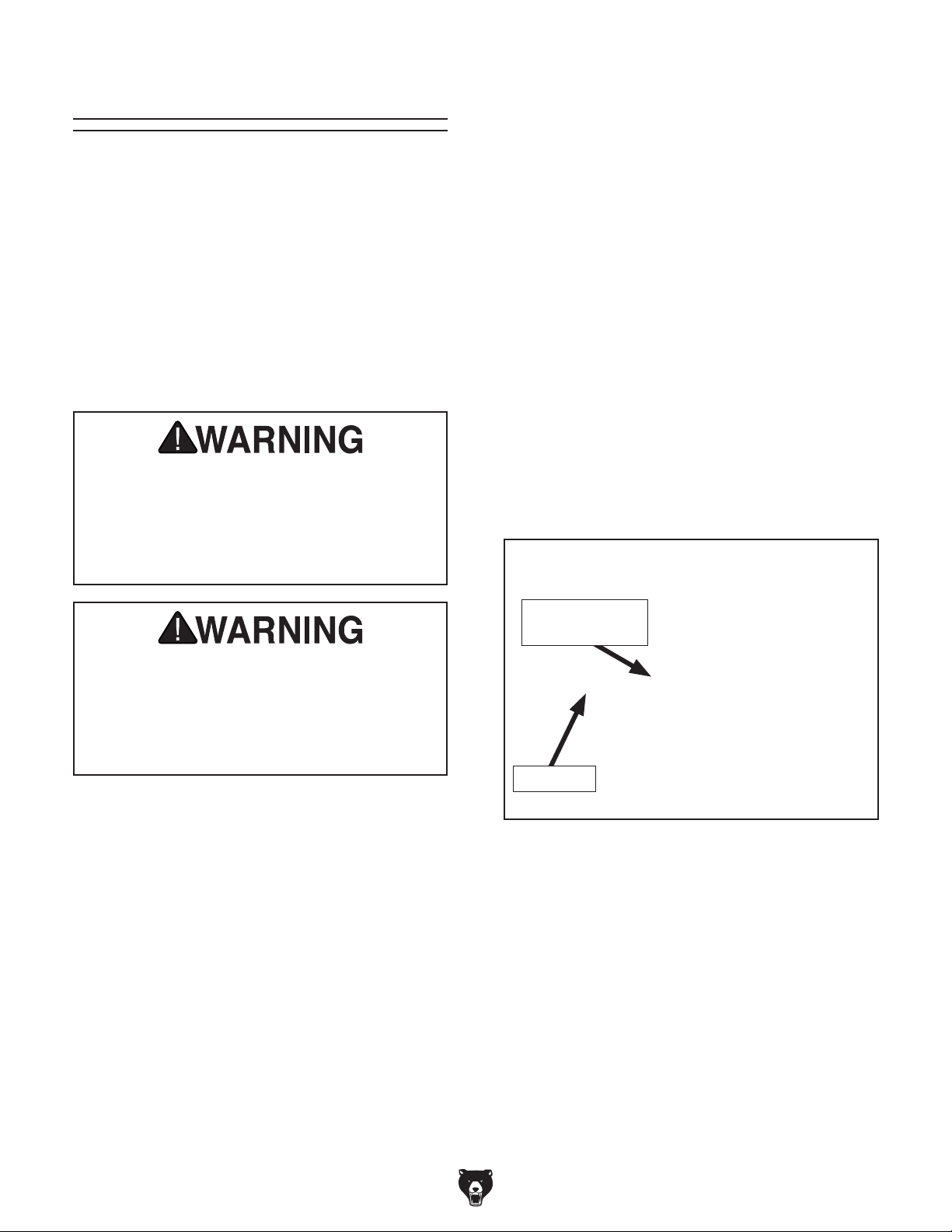
Faceplate
Refer to the prior Chuck Installation and Chuck
Removal subsections for instructions on installing
or removing the faceplate.
The faceplate included with your lathe can be
used for a wide range of operations, including
machining non-concentric workpieces, straight
turning between centers, off-center turning, and
boring.
The tools needed for mounting a workpiece will
vary depending on the type of setup you have.
Failure to properly secure workpiece to
faceplate could cause workpiece to be
thrown from lathe with deadly force. To
independent clamping devices to hold
Failure to properly secure workpiece to
faceplate could cause workpiece to be
thrown from lathe with deadly force. To
independent clamping devices to hold
To mount a non-concentric workpiece to a
faceplate:
1.
2.
across bed ways
3.
piece when clamping it to faceplate. If neces-
operation.
reduce this risk, use a minimum of THREE
DISCONNECT MACHINE FROM POWER!
Position appropriate device
to protect them from any potential damage
from workpiece contact during installation.
With help from another person or holding
device to support workpiece, position it onto
faceplate and clamp it in place with a minimum of three independent clamping devices
(see below for an example).
Be sure to take into account rotational and
cutting forces that will be applied to work-
sary, use counter-weights to balance assembly and use a dial indicator to make sure
workpiece is properly positioned for your
workpiece onto faceplate.
reduce this risk, use a minimum of THREE
workpiece onto faceplate.
Non-Cylindrical
Workpiece
Faceplate
Figure 37. Example of a workpiece clamped in a
faceplate.
-36-
Model G0949G (Mfd. Since 01/22)
Page 39
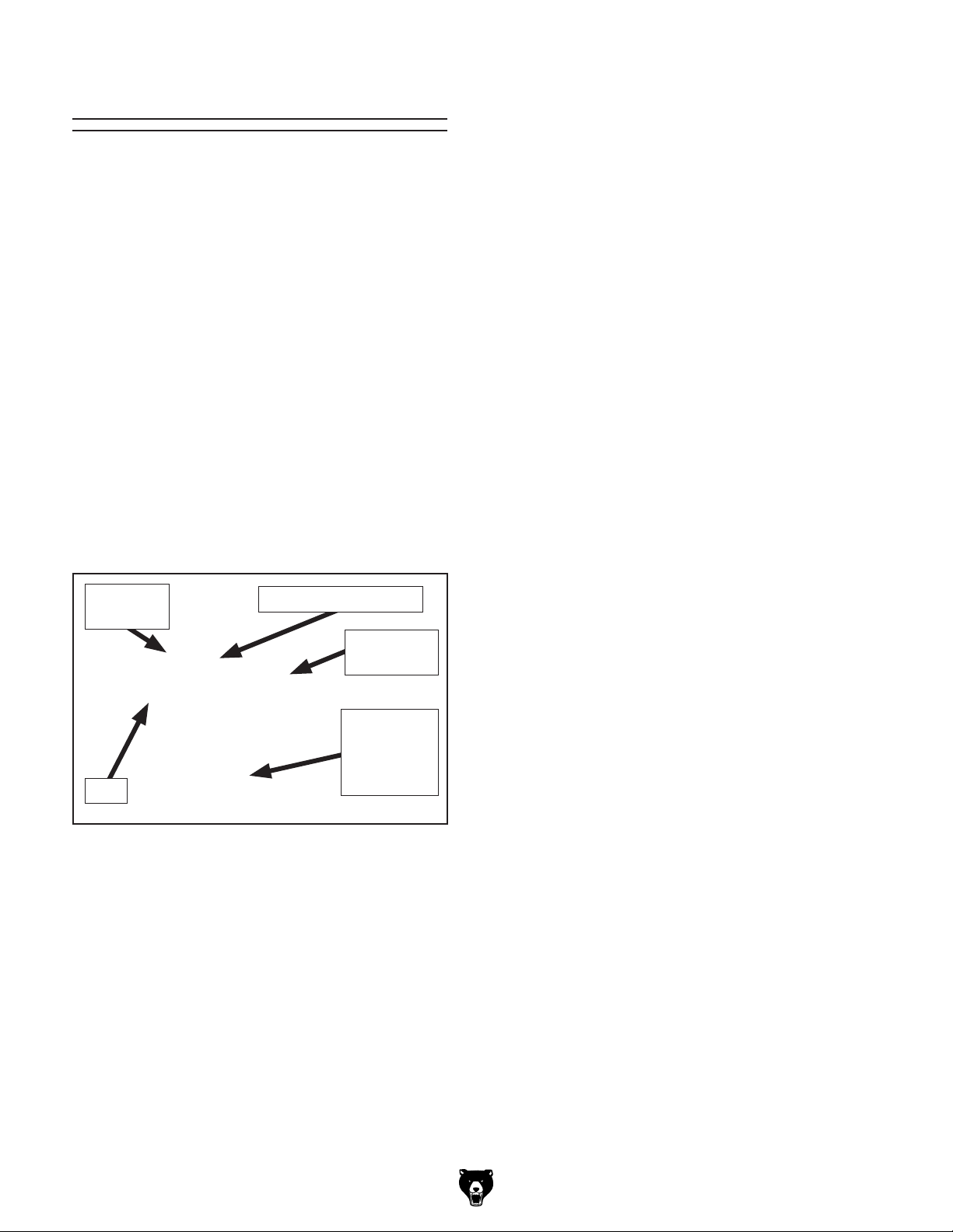
Tailstock
The tailstock is typically used to support long
workpieces at the side opposite the spindle, using
a live or dead center. It can also hold a tapered
drill bit (or a drill chuck with a regular drill bit) for
boring holes. Unlike boring done with a drill press
where the workpiece is fixed and the drill bit
rotates, the drill bit in a tailstock remains stationary while the workpiece is rotated by the spindle.
The entire tailstock can be repositioned and
locked in place along the length of the bed. An
independently controlled offset adjustment allows
the upper part of the tailstock to move perpendicular to the bedways so it can be aligned with
the spindle center (for concentric turning) or offset
from the spindle center (for tapered turning).
The tailstock quill also features independent
adjustment controls that allow it to be advanced
toward the spindle or locked firmly in position.
1. Rotate tailstock lock lever clockwise (facing
2.
3.
to lock tailstock against bedways.
1. Rotate quill lock lever counterclockwise to
2.
toward spindle or counterclockwise to move it
3.
quill.
Tailstock Quill Specs
Graduated Dial
Increments
One Full Revolution
Increments on Quill
................................ 0"–3" in 1⁄8" Increments
Inch
Metric
................................................. 0.0 01"
................................... 0.10 0"
.....................0–76mm in 1mm Increments
Positioning Tailstock
machine) to unlock tailstock from bedways.
Slide tailstock to desired position by pushing
it along the bedways.
Rotate tailstock lock lever counterclockwise
Using Quill
loosen quill.
Quill Lock
Lever
Quill
Figure 38. Tailstock controls and features.
Tailstock Lock Lever
Handwheel
Offset
Adjustment
S c re w
(1 of 2)
Quill
Turn quill handwheel clockwise to move quill
away from spindle.
Rotate quill lock lever clockwise to secure
Model G0949G (Mfd. Since 01/22)
-37-
Page 40

Installing Tooling
Note: If the tooling has an open hole in the end,
then a screw can be threaded into the end of the
tool to provide a solid surface for the quill pin to
push against when the quill is retracted for tool
removal. Otherwise, removal of such tooling may
be difficult.
To install tooling in tailstock:
1.
2.
3.
attempting to twist it—a firmly seated tool will
4.
is close to, but not touching, workpiece, then
5.
tool into workpiece.
1. Use shop rag to hold tool.
2.
forced out of quill.
The tailstock quill can be offset from the spindle
centerline for turning tapers. Offsetting the quill
toward the front of the lathe results in a taper at
the tailstock end. Conversely, offsetting the quill
toward the back of the lathe results in a taper at
the spindle end.
This tailstock uses a quill with an MT#3 taper
that accepts tapered arbors and drill bits
(see Figure 39).
With tailstock locked in place, unlock quill,
then use handwheel to extend it approximately 1".
Thoroughly clean and dry tapered mating
surfaces of quill and center, making sure no
lint or oil remains on tapers.
With a firm and quick motion, insert tool into
quill. Check to see if it is firmly seated by
not twist.
Unlock tailstock and move it until tip of tool
lock tailstock.
Start spindle rotation, unlock quill lock lever,
then turn quill handwheel clockwise to feed
Figure 39. Example of inserting tools into
tailstock.
Removing Tooling
Rotate quill handwheel counterclockwise to
fully retract quill into tailstock until tool is
Offsetting Tailstock
Note: The marks on the offset indicator (see
Figure 40) are arbitrary. For a precise offset, use
a dial indicator to check quill movement while
adjusting the screws.
Tool Needed Qty
Hex Wrench 4mm .............................................. 1
-38-
Model G0949G (Mfd. Since 01/22)
Page 41
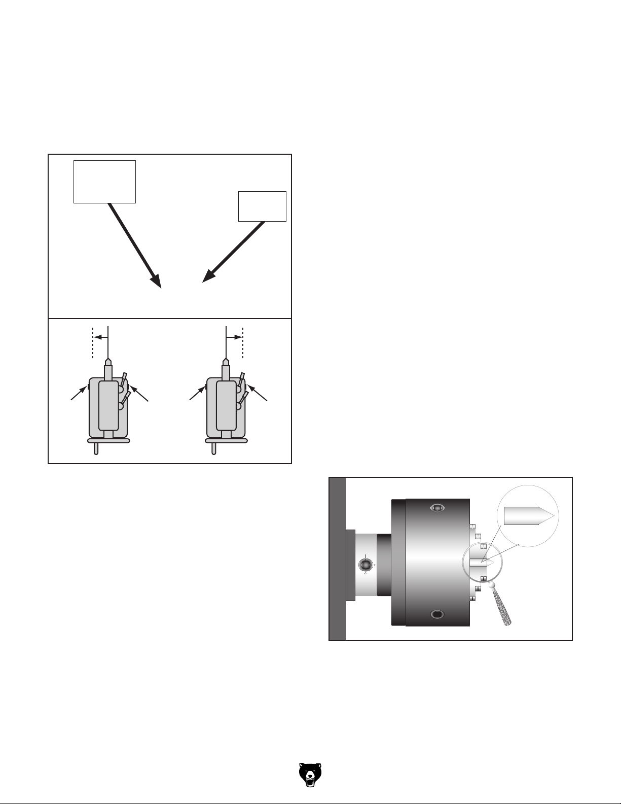
To offset tailstock:
This is an essential adjustment that should be verified or performed each time the tailstock is used
to turn concentric workpieces between centers
or immediately after offsetting the tailstock when
turning a taper. If the tailstock is not aligned with
the spindle centerline when it is supposed to be,
turning results will be inaccurate along the length
of the workpiece.
To align tailstock to spindle centerline:
1.
level from side to side and from front to back.
— If bedway is not level, correct this condition
before continuing with this procedure (refer
2.
3.
trated below.
Note: As long as this dead center remains
unmoved in the chuck, its point will remain
true to the spindle centerline. However, if the
center is removed and later returned to the
chuck, the point must be re-turned to once
again be true with the spindle centerline.
Move tailstock lock lever inward to loosen
1.
tailstock.
Rotate adjustment set screws in opposite
2.
directions for desired offset (see Figure 40).
Adjustment
Set Screw
(1 of 2)
Offset
Indicator
Aligning Tailstock to Spindle
Centerline
Items Needed Qty
Hex Wrench 6mm
Round Stock 2" x 6"
Precision Level
Use precision level to make sure bedway is
.............................................. 1
.......................................... 2
.................................................. 1
Turn
CCW
Figure 40. Set screw adjustment in relation to
Move tailstock lock lever outward to lock
3.
tailstock in place.
Turn
CW
tailstock movement.
Turn
CW
Turn
CCW
to Leveling section in this manual).
Center drill both ends of a piece of round
stock, then set it aside for use in Step 5.
Use another piece of round stock to make a
dead center. Turn it to a 60° point, as illus-
Figure 41. Turning a dead center.
Model G0949G (Mfd. Since 01/22)
-39-
Page 42
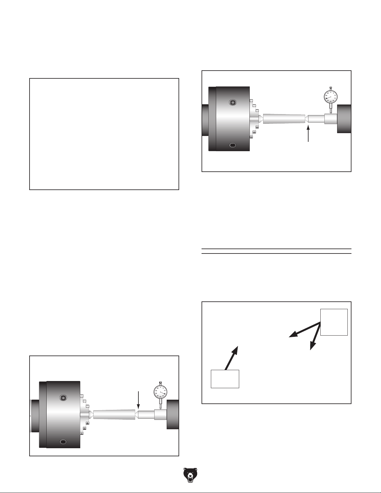
4. Install center in tailstock.
5.
Attach lathe dog to test stock from Step 2
,
below.
6. Turn 0.010" off stock diameter.
7.
Note: If necessary in the following step, refer
subsection for
8. Use calipers to measure both ends of work-
2
below.
— If test stock is thinner at tailstock end,
2
below.
9. Repeat Steps 6–8 until desired accuracy is
then mount it between centers, as shown
Figure 42. Example of stock mounted between
the centers.
move tailstock toward back of lathe 1⁄
the distance of taper amount, as shown
Looking down from above.
Move tailstock toward
back of lathe 1/2 the
amount of taper.
Figure 44. Adjust tailstock away from the
operator.
Mount test or dial indicator so that plunger is
on tailstock quill.
to the Offsetting Tailstock
piece.
— If test stock is thicker at tailstock end,
move tailstock toward front of lathe
1
the distance of taper amount, as shown
Move tailstock toward
1
front of lathe
/2 the
amount of taper.
Centers
Figure 45 shows the two MT#3 dead centers
included with the lathe. In addition, an MT#5 x
MT#3 spindle sleeve is included for mounting in
the spindle.
HSS
⁄
Adapter
Sleeve
Figure 45. Adapter sleeve and centers.
Dead
Centers
Looking down from above.
Figure 43. Adjust tailstock toward the operator.
-40-
Model G0949G (Mfd. Since 01/22)
Page 43
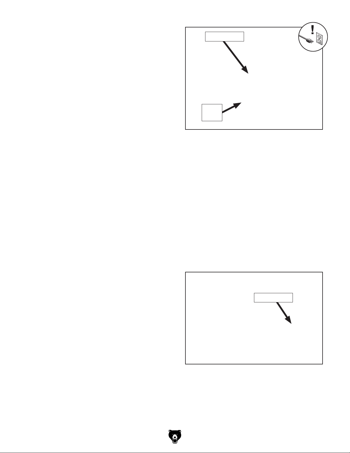
Dead Centers
1. DISCONNECT MACHINE FROM POWER!
2.
and center,
Note: This will prevent the tapered surfaces
from seizing due to operational pressures,
which could make it very difficult to remove
3.
4.
The
centers.
To remove the sleeve and center from the spindle,
insert a piece of round bar stock (or similar)
through the outside end of the spindle. Have
another person hold onto the sleeve and center
with a gloved hand or shop rag, then tap the bar
stock to knock the sleeve loose.
Either a carbide-tipped dead center or live center
can be used in the tailstock. Mounting instructions
are the same for both. The
shows
an example photo of a dead center mounted in a
tailstock.
A dead center is a one-piece center that does not
rotate with the workpiece and is used to support
long, slender workpieces.
Use the dead center in the spindle for operations
where the workpiece rotates with the center and
does not generate friction.
The tip of the center must be generously lubricated during the operation to avoid premature
wear and maximize smooth operation. Using low
spindle speeds will also reduce the heat and wear
from friction.
Mounting Dead Center in Spindle
Thoroughly clean and dry all threads and
mating surfaces of spindle bore
making sure that no lint or oil remains on
these surfaces.
Dead Center
Lathe
Dog
Figure 46. Example of using a dead center with
a faceplate and lathe dog.
Removing Center from Spindle
the center.
Mount chuck or faceplate onto spindle, which-
ever is correct for your operation.
Insert center into tapered spindle sleeve,
then insert center into spindle bore.
Figure below shows an example photo
of a dead center installed in spindle, using a
lathe dog and faceplate for turning between
Mounting Center in Tailstock
Figure below
Dead Center
Figure 47. Example of using a carbide-tipped
dead center installed in the tailstock.
Model G0949G (Mfd. Since 01/22)
-41-
Page 44

To mount a center in tailstock:
1.
2.
making sure no lint or oil remains on tapers.
To avoid premature wear of dead center
or damage to workpiece, use low spindle
Mounting Workpiece Between
3. Use quill handwheel to feed quill out from
4. Insert center into tailstock quill.
5.
Note: Only apply enough pressure with
tailstock quill to securely mount workpiece
ter against workpiece, or it may become
difficult to remove later, and it will result in
age workpiece and center.
1. DISCONNECT MACHINE FROM POWER!
2.
3.
4.
center holes, then mount workpiece between
centers and hold it in place with light pressure
5.
handwheel clockwise to apply pressure
against workpiece (see example below).
Note: Only apply enough pressure to securely
mount the workpiece between centers. Avoid
over-tightening the center against the workpiece,
or it may become difficult to remove later. Also,
over-tightening will result in excessive friction and
heat, which may damage the workpiece or center.
Centers
speeds and keep tip of dead center mounted
in tailstock well lubricated.
DISCONNECT MACHINE FROM POWER!
Thoroughly clean and dry tapered mating
surfaces of tailstock quill bore and center,
casting approximately 1".
Note: The maximum quill travel is 3
we do not recommend extending the quill
more than 2" or stability and accuracy will be
reduced.
Seat center firmly into quill during workpiece
installation by rotating quill handwheel clockwise to apply pressure with center engaged
in center hole of workpiece.
1⁄8", but
Drill center holes in both ends of workpiece.
Install dead center in spindle with lathe dog
and chuck, faceplate or drive plate, then
install live center or carbide-tipped dead center in tailstock.
Lubricate dead center point and workpiece
from tailstock center.
Seat center firmly into quill by rotating quill
between centers. Avoid overtightening cen-
excessive friction and heat, which may dam-
Removing Center from Tailstock
To remove the center from the quill, hold onto it
with a gloved hand or shop rag, then rotate the
quill handwheel counterclockwise to draw the quill
back into the casting until the center releases.
-42-
Figure 48. Example photo of a workpiece
mounted between the centers.
Model G0949G (Mfd. Since 01/22)
Page 45
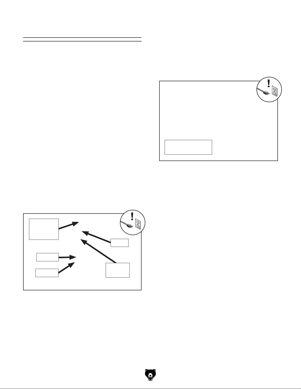
Steady Rest
The steady rest supports long shafts and can
be
bedway
components shown below to better understand
the controls before using it.
5. Use finger adjustment knobs (see Figure
50) to position fingers so they just touch
workpiece without causing deflection.
mounted anywhere along the length of the
. Familiarize yourself with the steady rest
Tools Needed Qty
Open-End Wrenches 14, 19mm ........................ 1
Hex Wrench 5mm
To install and use steady rest:
1.
DISCONNECT MACHINE FROM POWER!
2. Thoroughly clean all mating surfaces, then
place steady rest base on bedways so triangular notch fits over bedway prism.
Position steady rest with base clamp where
3.
required to properly support workpiece, then
tighten hex nut shown in Figure 49 to secure
it in place.
.............................................. 1
Note: The maximum quill travel is 31⁄8", but
we do not recommend extending the quill
more than 2" or stability and accuracy will be
reduced.
Finger Adjustment
Knob (1 of 3)
Figure 50. Example of workpiece mounted in
steady rest.
6. Tighten finger lock nuts to secure settings.
Loosen finger lock nuts (see Figure 49) so
4.
position of fingers can be adjusted.
Finger
Adjustment
Knob
Finger
Hex Nut
Finger
Hex Bolt
Figure 49. Steady rest components.
Lock Nut
Note: To reduce the effects of friction, lubri-
cate the fingers with anti-sieze lubricant such
as Grizzly Model T23962 ISO Moly-D Way
Oil (see Accessories on Page 57) during
operation.
Model G0949G (Mfd. Since 01/22)
-43-
Page 46
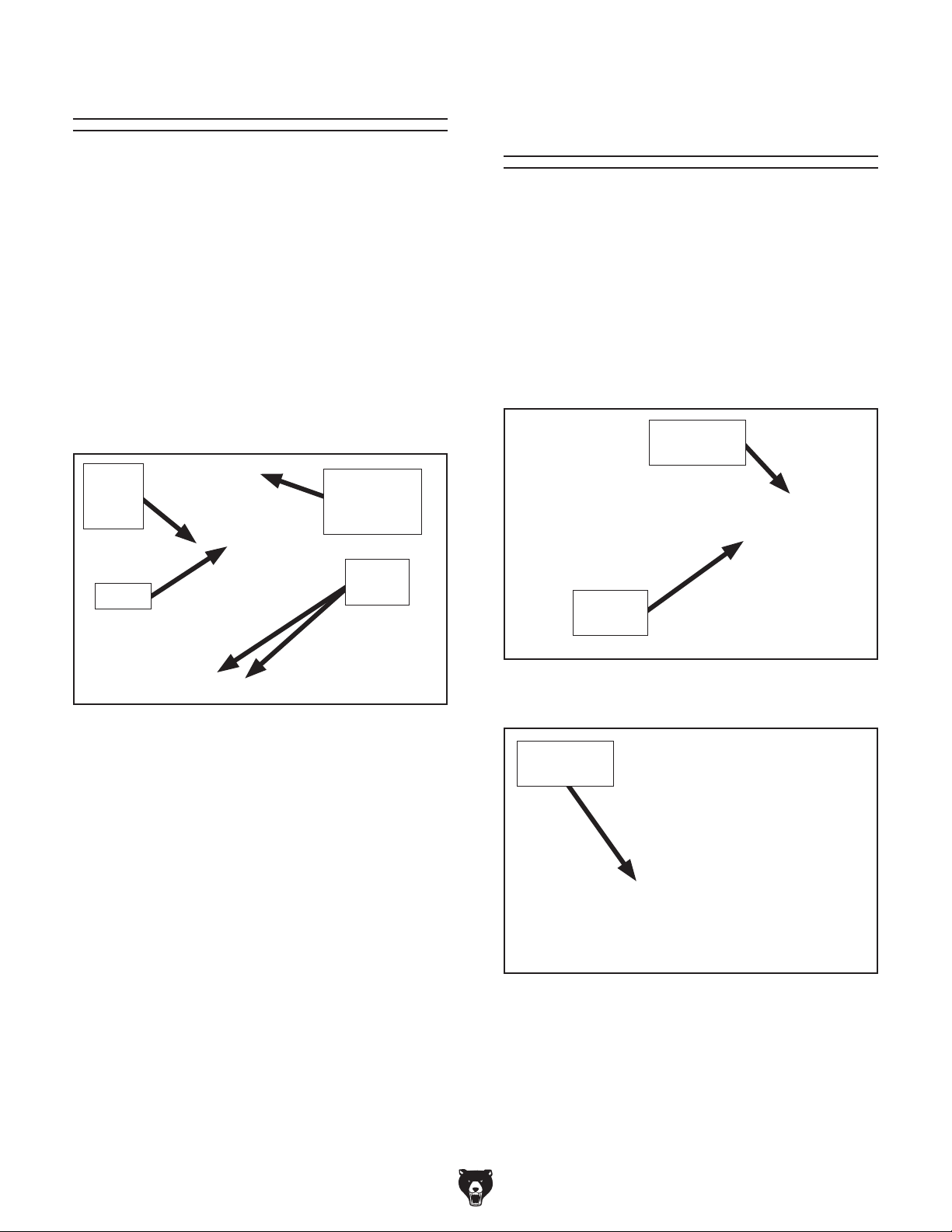
Follow Rest Carriage & Slide
Tip: To reduce the effects of friction, lubricate the
finger tips with generous amounts of anti-sieze
lubricant during operation.
The follow rest mounts to the saddle with two cap
screws (see Figure 51). It is used on long slender parts to prevent workpiece deflection from
the pressure of the cutting tool during operation.
Adjust the finger adjustment knobs in the same
manner as those on the steady rest.
Tools Needed Qty
Hex Wrench 5mm .............................................. 1
Open-End Wrench 14 mm
Finger
Lock
Nut
.................................. 1
Finger
Adjustment
Knob
Locks
The carriage, cross slide, and compound rest
have locks that can be tightened to provide additional rigidity during operation, especially during
heavy- cuts.
See Figures 52–53 to identify the locks for each
device.
Tool Needed Qty
Hex Wrench 6mm .............................................. 1
Cross Slide
Lock
Finger
Figure 51. Follow rest components.
Cap
Screws
Carriage
Lock
Figure 52. Location of carriage and cross slide
locks.
Compound
Rest Lock
Figure 53. Location of compound rest lock.
-44-
Model G0949G (Mfd. Since 01/22)
Page 47
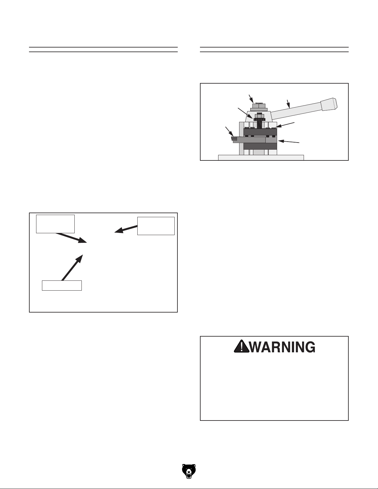
Compound Rest Tool Post
The quick-change tool post (see Figure below) is
a 200-series design.
To install tool in tool post:
1
Position tool in holder so cutting edge extends
just enough to allow tool to cut freely—but no
avoid chipping.
2. Secure tool with at least two set screws.
3.
line, as instructed in next subsection.
The compound rest handwheel has an indirectread graduated scale. This means that the distance shown on the scale represents the actual
distance the cutting tool moves. The base of the
compound rest has another graduated scale used
for setting the cutting tool to a specific angle.
Graduated Dial
Increments
One Full Revolution
Tool Needed Qty
Open-End Wrench 19mm .................................. 1
To set the compound rest at a certain angle:
Loosen two cap screws at the base of com-
1.
pound rest (see Figure 54).
Cap Screw
................................................. 0.0 01"
...................................0.200"
(1 of 2)
Compound
Rest
Thumb
Wheel
Cutting
Tool
Figure 55. Example of tool mounted in tool post.
Tool holders can be quickly loaded and unloaded
using the lock lever, and rotated by loosening the
top nut. Tools up to
ing the tool holder set screws. The thumb wheel
rotates to adjust cutting tool height.
Installing Tool in Tool Post
Tools Needed Qty
Open-End Wrench or Socket 27mm ................. 1
Hex Wrench 5mm
Top Nut
5
⁄8" can be secured by tighten-
.............................................. 1
Lock Lever
Tool Post
Set Screw
Tool Holder
Angle Scale
Figure 54. Compound rest angle adjustments.
2. Rotate rest to desired angle, as indicated by
scale at base, then retighten two cap screws.
Tip: The first time you set the angle of the
compound rest for cutting threads, mark the
location on the cross slide as a quick reference point. This will allow you to quickly
return the compound rest to that exact angle
the next time you need to cut threads.
Model G0949G (Mfd. Since 01/22)
.
more. The cutting edge must be well supported to ensure good cutting results and
Over-extending a cutting tool from the post
will increase risk of tool chatter, breakage,
or tool loosening during operation, which
could cause metal pieces to be thrown at
the operator or bystanders with great force.
DO NOT extend a cutting tool more than 2.5
times the width of its cross-section (e.g.,
2.5 x 0.5" = 1.25").
Adjust cutting tool height to spindle center-
-45-
Page 48
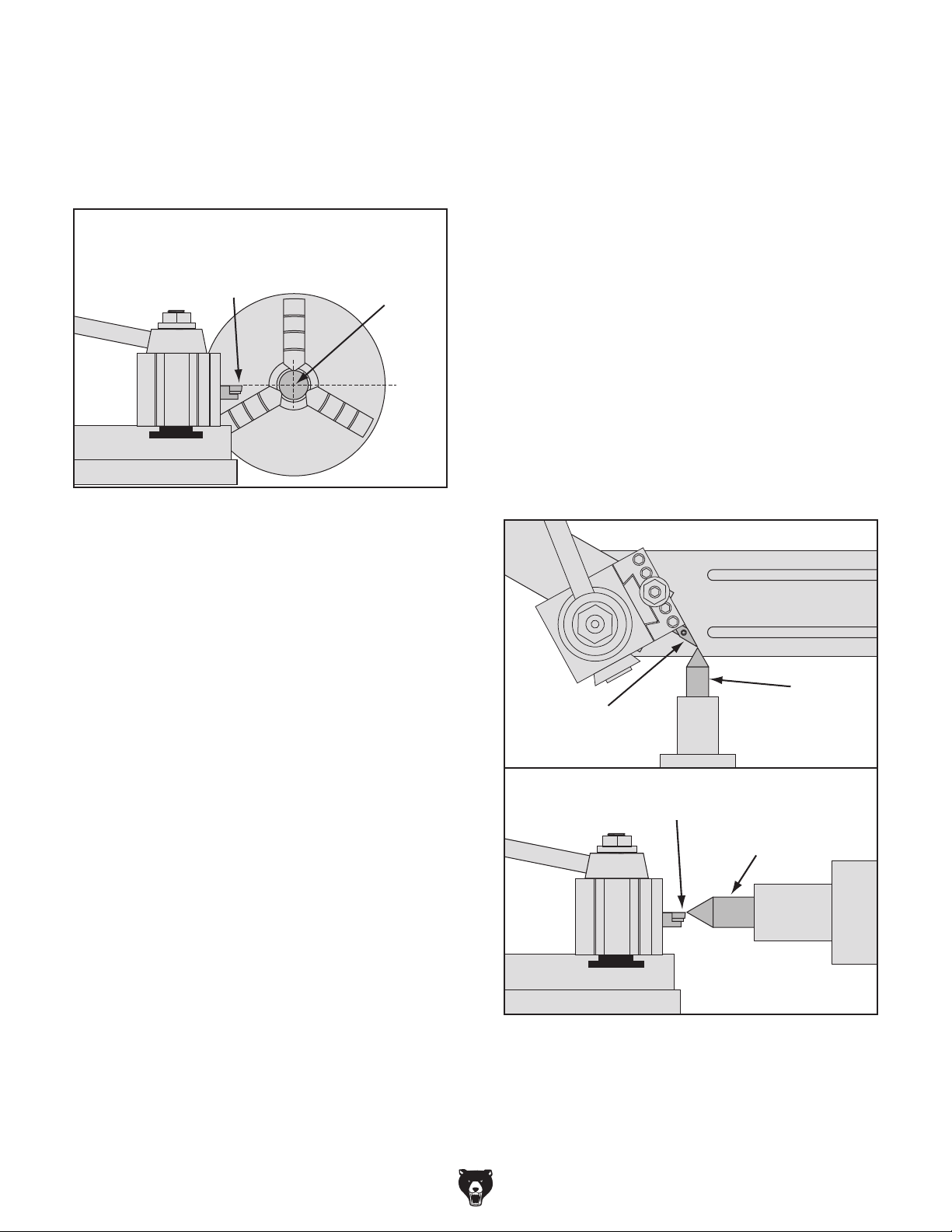
Aligning Cutting Tool with Spindle
There are a number of ways to check and align
the cutting tool to the spindle centerline. If necessary, you can raise the cutting tool by placing
steel shims underneath it. The shims should be
as long and as wide as the cutting tool to properly
support it.
Below are two common methods:
• Move the tailstock center over the cross slide
to measure the distance
cutting tool height so
•
tailstock
Aligning Tailstock To Spindle Centerline
for detailed instructions).
For most operations, the cutting tool tip should be
aligned with the
centerline, as illustrated
below.
To align cutting tool with tailstock center:
1.
2.
3.
4.
aligned vertically with center tip, as illustrated
below.
Centerline
spindle
Tools Needed Qty
Hex Wrench 5mm .............................................. 1
Open-End Wrench or Socket 17mm
Steel Shims
Cutting Tool
Precision Ruler
Tailstock Center
....................................... As Needed
....................................................... 1
.................................................. 1
................................................. 1
.................. 1
Cutting
Tool
Figure 56. Cutting tool aligned with spindle
centerline (viewed from tailstock).
and use a fine ruler
from the surface of the cross slide to the tip
of the center. Adjust the
it is the same distance above the cross slide
as the tailstock center.
Align the tip of the cutting tool with a
center, as instructed in the following procedure. For this to work, the tailstock must
be aligned to the spindle centerline (refer to
Spindle
Center
Line
Mount cutting tool in tool post, then secure
post so tool faces tailstock.
Install center in tailstock, and position center
tip near cutting tool tip.
Lock tailstock and quill in place.
Adjust height of cutting tool so tool tip is
(Top View)
Tailstock
Center
Cutting
Tool
Cutting
Tool
Tailstock
Center
(Side View)
Figure 57. Cutting tool aligned to the tailstock
center.
-46-
Model G0949G (Mfd. Since 01/22)
Page 49
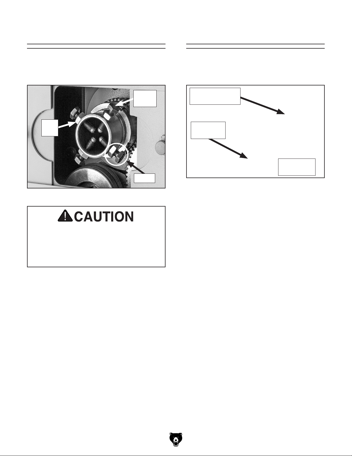
Manual FeedSpindle Spider
This lathe is equipped with a set of outboard
spindle supports otherwise known as a "spider"
(see Figure 58).
Spider
Screw
Jam
Nut
Spider
Figure 58. Spindle spider components.
Remove spider screws when not in use.
Always DISCONNECT LATHE FROM POWER
when installing, removing, or adjusting spider screws. Ignoring this warning can lead
to personal injury or machine damage.
The spider is especially designed for supporting
gun barrels during chambering operations; however, it is a great support option for almost any
long workpiece that extends through the outboard
side of the spindle.
The tips of the spider screws have brass wear
pads that hold the workpiece without causing
indents in the finish.
When spider screws are installed, always use the
jam nuts to lock each spider screw in position.
Merely tightening the spider screws against the
workpiece and leaving the jam nuts loose is not
safe. Spiders screws that loosen during operation
can crash into the lathe end cover.
The cutting tool can be manually fed into the
workpiece using the carriage, cross slide, and
compound rest handwheels shown below.
Compound Rest
Handwheel
Carriage
Handwheel
Cross Slide
Handwheel
Figure 59. Manual feeding controls.
Carriage Handwheel
The carriage handwheel moves the carriage left
or right along the bed. It has a graduated dial with
0.01" increments. One full revolution moves the
carriage 1.2".
Cross Slide Handwheel
The cross slide handwheel moves the tool toward and away from the work. Adjust the position
of the graduated scale by loosening the thumb
knob, holding the handwheel with one hand and
turning the dial with the other, then tightening the
thumb knob. The cross slide handwheel has a
direct-read graduated dial, which shows the total
amount of material removed from the diameter of
the workpiece. The dial has 0.002" increments,
and one full revolution moves the slide 0.2". Rotate the dial collar 180° to read in metric units.
Cross Slide Handwheel
The compound rest handwheel moves the cutting
tool linearly along the set angle of the compound
rest. Adjust the position of the graduated scale in
a similar manner with handwheel and dial. The
compound rest angle is set by hand-rotating it
and securing in place with four hex nuts. The
compound rest has an indirect-read graduated
dial with 0.001" (0.025mm) increments. One full
revolution of the handwheel moves the slide 0.1".
Model G0949G (Mfd. Since 01/22)
-47-
Page 50
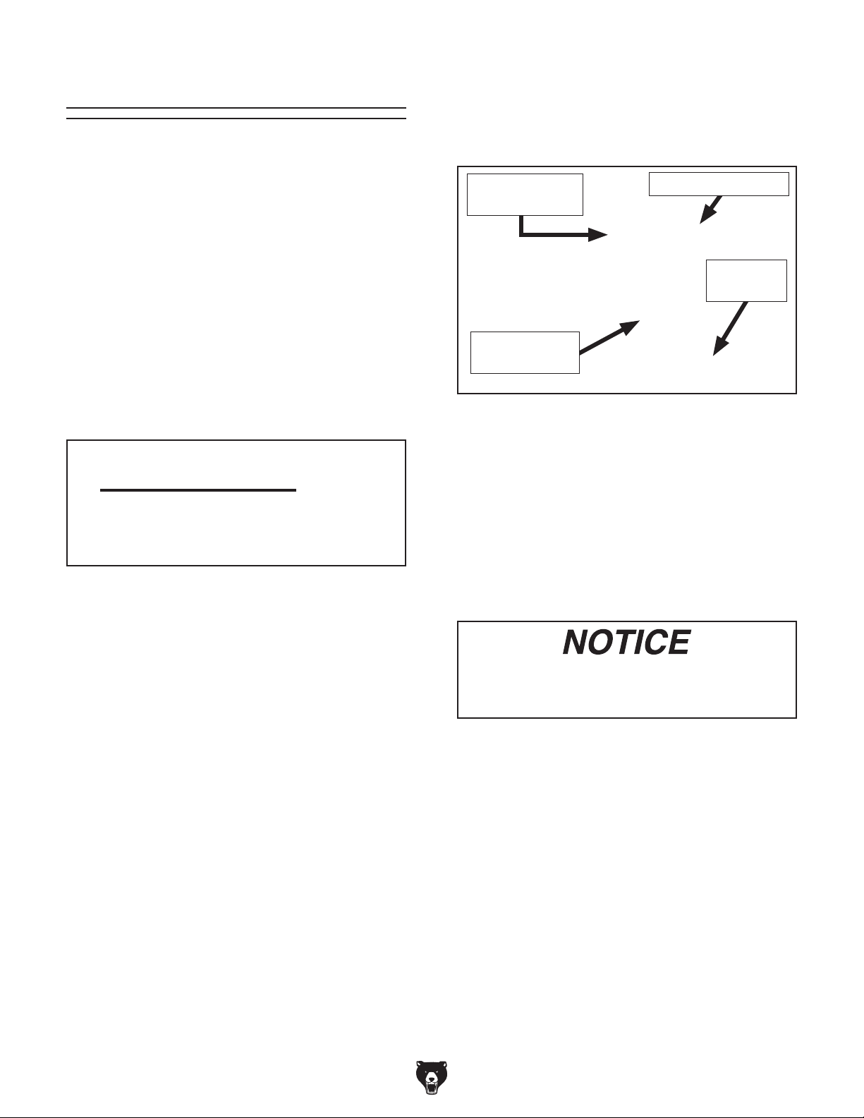
Spindle Speed
Using the correct spindle speed is important for
getting
maximizing tool life.
To set the spindle speed for your operation, you
will need to: 1) Determine the
spindle speed
for the cutting task, and 2)
lathe
controls to produce the required spindle speed.
Many variables affect the optimum spindle speed
to use for any given operation
important are the recommended cutting speed for
the workpiece material and the diameter of the
workpiece, as noted in the formula shown below.
Cutting speed, typically defined in feet per minute
(FPM), is the speed at which the edge of a tool
moves across the material surface.
A recommended cutting speed is an ideal speed
for cutting a
the desired finish and optimize tool life.
The books
Machine
Shop Practice
vide excellent recommendations for which cutting
speeds to use when calculating the spindle speed.
The
also provide a wealth of additional
information about the variables that affect cutting
speed and
A
spindle speed calculators that can be found on
the internet.
take into
account the applicable variables in order to
mine the best spindle speed for the operation.
safe and satisfactory results, as well as
Setting Spindle Speed
Selecting one of the two spindle speed ranges is
performed by positioning the spindle speed range
lever (see Figure 61) to Low (L) or High (H) range.
best
Configure the
Determining Spindle Speed
, but the two most
*Recommended
Cutting Speed (FPM) x 12
Dia. of Cut (in inches) x 3.14
Spindle
Speed
=
(RPM)
*Double if using carbide cutting tool
Figure 60. Spindle speed formula for lathes.
Spindle Speed
Digital Readout
Spindle Speed
Range Lever
Figure 61. Spindle range and speed levers.
The spindle speed dial is then used to determine
the precise spindle speed within the selected
speed range.
Note: To maximize spindle torque, always use low
range RPM speeds for heavier cuts. If required
spindle speed exceeds 515 RPM (low range
maximum) it is acceptable to use higher RPM
range with lighter cuts.
Spindle Speed Dial
FWD/REV
Switch
type of material in order to produce
se sources
lso, there are a large number of easy-to-use
-48-
Machinery’s Handbook or
, and some internet sites, pro-
they are a good educational resource.
These sources will help you
deter-
To avoid damaging gears, ALWAYS make
sure the spindle is completely stopped
BEFORE moving the spindle speed lever.
Follow along with this example for setting the
spindle speed for the Model G0949G to gain a
better understanding of the task:
To set spindle speed to 150 RPM:
Move FWD/REV switch to "0".
1.
2. Move spindle speed range lever to Low (L)
position (see Figure 61).
Move FWD/REV switch to FWD, and press
3.
the START button.
Adjust spindle speed dial until spindle speed
4.
digital readout shows 150 RPM.
Model G0949G (Mfd. Since 01/22)
Page 51
Power Feed
Both the carriage and cross slide have power feed
capability when the carriage is engaged with the
feed rod. The rate that these components move
per revolution of the feed rod is controlled by the
quick-change gearbox levers and dial positions
and the end gear configuration.
The feed per revolution and the spindle speed
must be considered together—this is the feed
rate. The sources you use to determine the optimum spindle speed for an operation will also
provide the optimal feed to use with that spindle
speed.
To avoid damaging the lathe, ALWAYS make
sure the spindle is completely stopped
BEFORE using the headstock controls to
make changes.
Power Feed Controls
Use Figures 62–66 and the following descriptions to understand the power feed controls.
Note: Before using power feed, you may have to
reconfigure the end gears, depending on how they
are set up. Refer to End Gears on Page 51 for
detailed instructions.
Often, the experienced machinist will use the
feeds and speeds given in their reference charts
or web calculators as a starting point, then make
minor adjustments to the feed rate (and sometimes spindle speed) to achieve the best results.
The carriage can alternately be driven by the
leadscrew for threading operations. However, this
section only covers the use of the power feed
option for the carriage and cross slide components for non-threading operations. To learn how
to power the carriage for threading operations,
refer to Threading on Page 54.
If the feed selection lever and the half nut
are engaged at the same time, machine
damage could occur. Even though there is
a lock-out device to prevent this, it could
break if forced.
Before using any power feed or threading
operations, make sure to loosen carriage
lock first. Ignoring this warning can cause
serious machine damage.
B
A
Figure 62. Power feed controls on the
headstock.
A. Feed Direction Selector: Selects direction
of carriage travel for power feed relative to
the rotation direction of spindle. When lever
is positioned as shown in Figure 62, carriage
will move left (toward the spindle), or cross
feed will travel toward rear of lathe when spindle is rotating counterclockwise (or toward
front of lathe). When lever is positioned in
opposite direction, carriage will move right
(toward tailstock), or cross feed will travel
toward front of lathe when spindle is rotating
clockwise (or toward the rear of lathe).
B. Feed Rate Selector: Sets desired feed/
thread rate. Refer to Setting Power Feed
Rate subsection on Page 50 for detailed
instructions.
C
Model G0949G (Mfd. Since 01/22)
Feed/Thread Selector: Left position selects
C.
thread. Right position selects feed.
-49-
Page 52
D. Feed Rate Chart: Used to determine com-
bination of selector settings and end gear
combinations to achieve desired result (see
Figure 63).
D
E. Feed Selection Lever: Changes power feed
to either cross slide or carriage.
When lever is in left and down position, cross
slide is selected. When lever is in right and up
position, carriage is selected. In middle position, neither cross slide or carriage will move.
Note: When using this lever, you may need
to slightly rotate the handwheel of the component you are trying to engage, so that the
apron gears can mesh.
. Half-Nut Selection Lever: Engages/disen-
F
gages half nut for threading operations.
Setting Power Feed Rate
The feed rate chart displays settings for headstock feed controls for feed rates.
Using the controls on the lathe, follow along with
the example below to better understand how to
set up the lathe for the desired power feed rate.
Figure 63. Feed rate chart.
E
Figure 64. Apron power feed controls.
Examining the chart, you will see a series of
boxes separated by slashes. The top number is
the carriage feed rate, the bottom number is the
cross-slide feed rate, as shown in Figure 65.
Carriage
Feed
Rate
Cross
Slide
Feed
Rate
F
Figure 65. Location of 0.0075 in./rev. on feed
chart.
Using the controls on the lathe, follow along with
the example below to better understand how to
set the lathe for the desired power feed rate.
End Gear
Configuration
0.0075
in./rev.
-50-
Model G0949G (Mfd. Since 01/22)
Page 53
To set power feed rate of 0.0075 in./rev:
1. Locate cell on feed rate chart that lists 0.0075
in./rev., as shown in Figure 66.
Feed
Direction
Selector
Feed Rate
Selector
Feed/
Thread
Selector
End Gears
The following subsections explain how to configure
the end gears. The gears must be configured
according to the feed and threading charts in
order to perform specific power feed and threading
operations (see Figure 67).
To set the gears up properly, according to the
particular gears and positions shown in the charts,
you need a basic understanding of gear positioning
on the lathe and how this is represented in
the chart illustrations. In Figure 67, identify the
following:
Figure 66. Feed rate levers positioned for
0.0075 in./rev.
2. Locate the applicable positions for feed direc-
tion selector, feed rate selector, and feed/
thread selector.
Locate end gear configuration callout, and
3.
position end gears in correct configuration,
as shown on feed rate chart. For this configuration install a 45T gear in Z1 position and
mesh it with a 70T gear at Z4 position. Install
a 75T gear in Z2 position and mesh it with
25T gear at Z3 position.
Note: The L gear is always 90T in power feed
configuration.
4. Move selector levers to correct positions:
feed direction selector to left, feed rate selector to position "A", and feed/thread selector to
right (feed setting), as shown in Figure 66.
Move leadscrew feed rod selection lever up.
5.
The carriage is now set up for a power feed
rate of 0.0075 in./rev.
—40T gear
—Z1 & Z2 (outer & inner) combination gear
—Z3 & Z4 (inner & outer) combination gear
—L gear
40T Gear
Z1
(Outer)
Z3
(Inner)
L Gear
Figure 67. End gear identification.
The following subsections explain how to configure the end gears, which are accessed by
removing the end-gear cover on the side of the
headstock.
Z2
(Inner)
Z4
(Outer)
Power Feed Configuration
Gear selection depends upon which feed speed
is selected (see Figure 68). To complete a power
feed configuration, install a 75T or 80T gear in Z2
position, a 45T gear in Z1 position, a 20T, 25T, or
30T gear in Z3 position, and a 70T or 80T gear in
Z4 position. Install a 90T gear in L position. Mesh
gears together and secure in place (see Figures
69–70).
Model G0949G (Mfd. Since 01/22)
Note:
configuration.
The L gear is always a 90T in power feed
-51-
Page 54
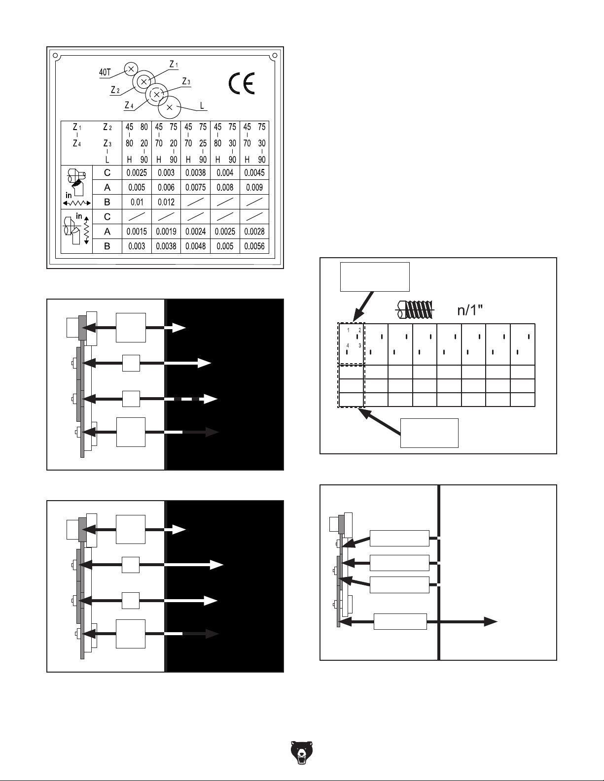
Inch Threading Configuration
Install a spacer in the Z1 position, and install end
gears in the Z2, Z3, Z4, and L positions. Mesh
the Z2 gear with the Z3 gear, and mesh the Z4
gear with the L gear. Just like the Z1/Z2 and Z3/
Z4 gears, the L gear can be installed in either the
inner or outer position on the shaft. The "H" designation in the L row shown in the chart below indicates a spacer is to be installed in that position.
Loosen the mounting hardware necessary and
adjust backlash to between 0.002"–0.004".
Tighten the hardware once the adjustment is
complete and the gears are meshed correctly. Set
the feed rate selector to A, B, or C.
Figure 68. Power feed chart.
40T
Gear
Z2
Z3
L
Gear
Figure 69. Power feed inner gear identification.
40T
Gear
End Gear
Configuration
70
HHH H H
Z
Z
45
ZZ
40
90
L
B
8
A
16
C
32
70
40 40 30 40 7075 75
50
18
36
50 55 50 60
9
10
20
40
H
70 55 80
11
22
44
H H
H
12
24
48
13
26
52
6070
HHHH H80 80 80 8060 65
14
28
56
Feed Rate
Selectors
Figure 71. Inch TPI threading configuration.
Z2 Position
Z1
Z4
L
Gear
Figure 70. Power feed outer gear identification.
-52-
Z3 Position
Z4 Position
L Position
Figure 72. Inch end gear configuration.
Model G0949G (Mfd. Since 01/22)
Page 55
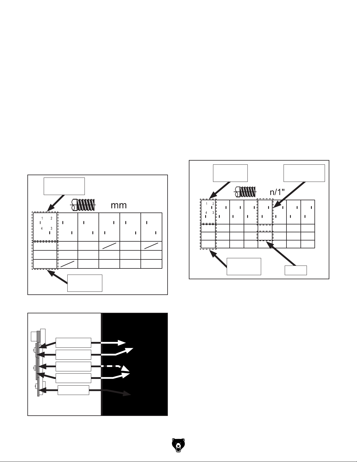
Metric Threading Configuration
Install a spacer or an end gear in the Z1 and L
positions, as applicable. Install end gears in the
Z2, Z3, and Z4 positions. Mesh the Z1 gear with
the Z4 gear, and mesh the Z3 gear with the L
gear, as applicable. Or mesh the Z2 gear with the
Z3 gear, and mesh the Z4 gear with the L gear, as
applicable. Just like the Z1/Z2 and Z3/Z4 gears,
the L gear can be installed in either the inner or
outer position on the shaft. The "H" designation
in the L row shown in the chart below indicates a
spacer is to be installed in that position.
Loosen the mounting hardware necessary and
adjust backlash to between 0.002"–0.004".
Tighten the hardware once the adjustment is
complete and the gears are meshed correctly. Set
the feed rate selector to A, B, or C.
End Gear
Configuration
End-Gear Configuration Example
Follow the example below to better understand
how to read the gear charts and configure the end
gears accordingly.
Tools Needed Qty
Hex Wrench 5mm .............................................. 1
Open-End Wrench 5mm
To configure end gears for threading 22 TPI:
1. Locate 22 TPI on inch thread chart, then look
at numbers provided at the top of column.
These are end gears that need to be used
in 22 TPI configuration. Note the feed rate
selector setting (see Figure 75).
End Gear
Positions
.................................... 1
End Gear
Configuration
Z
Z
Z
Z
L
C
A
B
80
70 70
30
55
H H
75
0.4
0.8
75 40 45 50 80
63
80
0.5
60
H
80
6345
80
H H H
1.251.0
2.52.0
80
60
0.75
1.5
80
1.75
3.53.0
6363
50
Feed Rate
Selector
Figure 73. Metric TPI threading configuration.
Z2 Position
Z1 Position
Z3 Position
70
HHH H H
Z
Z
45
ZZ
40
90
L
B
8
A
16
C
32
70
40 40 30 40 7075 75
50
18
36
50 55 50 60
9
10
20
40
H
70 55 80
11
22
44
H H
H
12
24
48
13
26
52
6070
14
28
56
Feed Rate
Selector
22 TPI
Figure 75. 22 TPI threading configuration.
DISCONNECT MACHINE FROM POWER!
2.
3. Remove end-gear cover.
Collect 70T, 40T, 55T, and 80T end gears.
4.
HHHH H80 80 80 8060 65
Z4 Position
L Position
Figure 74. Metric feed chart end gears.
Model G0949G (Mfd. Since 01/22)
-53-
Page 56
Z3 (Inner)
and Z4
(Outer)
Positions
Z1 (Outer)
and Z2
(Inner)
Positions
L Position
End Gear
Positions
70
HHH H H
Z
Z
45
ZZ
40
90
L
B
8
A
16
C
32
Feed Rate
70
40 40 30 40 7075 75
50
18
36
50 55 50 60
9
10
20
40
Selector
Configuration
H
70 55 80
11
22
44
H H
H
12
24
48
22 TPI
End Gear
6070
HHHH H80 80 80 8060 65
13
14
26
28
52
56
Figure 76. End gear placement.
5. Install 80T gear on L shaft.
Install 55T gear on Z3/Z4 shaft in Z3 position.
6.
Install 40T gear on Z3/Z4 shaft in Z4 position.
7.
Install 70T gear on Z1/Z2 shaft in Z2 position.
8.
Install 40T gear on Z3/Z4 shaft in Z4 position.
9.
Loosen mounting hardware necessary and
10.
adjust backlash to between 0.002"–0.004".
Tighten hardware once adjustment is complete and gears are meshed correctly.
Re-install end gear cover.
11.
Threading
Figure 77. 22 TPI threading configuration.
Using the controls on the lathe, follow the example below to understand how to set up the lathe
for the desired threading operation.
To set levers for 22 TPI:
Locate 22 TPI on inch threading chart shown
1.
in Figure 78.
Feed
Feed
Direction
Rate
Selector
Selector
Feed/
Thread
Selector
The following subsections will describe how to
use the threading controls and charts to set up the
lathe for a threading operation. If you are unfamiliar with the process of cutting threads on a lathe,
we strongly recommend that you read books,
review industry trade magazines, or get formal
training before attempting any threading projects.
Headstock Threading Configuration
The threading charts on the headstock face (see
Figure 77) display settings for inch and metric
threading.
-54-
Figure 78. Feed direction and feed/thread
selector settings for 22 TPI.
Install gears as instructed in End-Gear
2.
Configuration Example on Page 53.
On inch thread chart, locate correct position
3.
of feed rate selector. Shift lever to position A,
as shown in Figure 78.
Position feed direction selector to left, and
4.
feed/thread selector to right, as shown in
Figure 78.
The lathe is now set up to cut 22 TPI threads.
Model G0949G (Mfd. Since 01/22)
Page 57
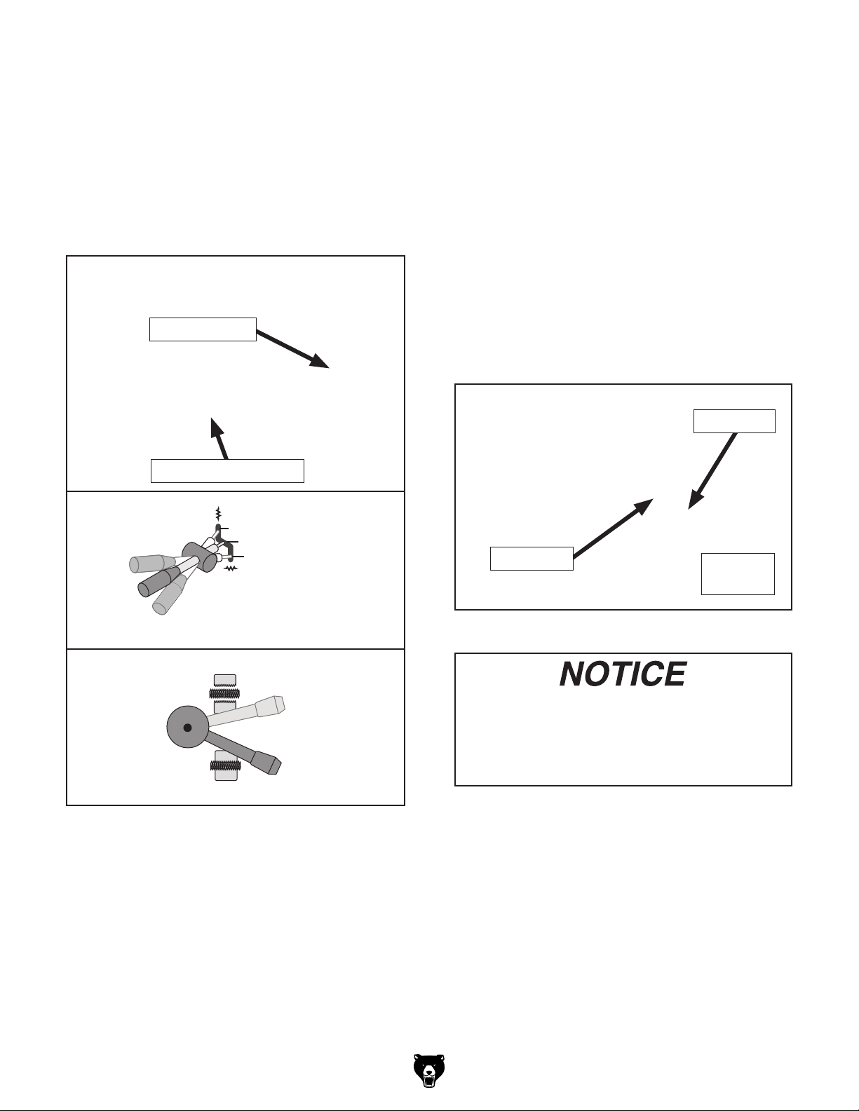
Apron Threading Configuration
Lever
The half nut lever engages the carriage with the
leadscrew, which moves the carriage and cutting
tool along the length of the workpiece for threading operations (see Figure 79).
IMPORTANT: Make sure the feed lever and feed
selection lever are in the disengaged position
before attempting to engage the half nut.
Half Nut Lever
Feed Selection Lever
Thread Dial
Tool Needed Qty
Open-End Wrench 14mm .................................. 1
The numbers on the thread dial are used
with the thread dial chart to show when to
engage the half nut during inch threading operat i o n s . L o o s e n t h e c a p s c r e w o n t h e t h r e a d d i a l
(see Figure 80), pivot the gear teeth so they mesh
with the leadscrew threads, then tighten the cap
screw.
Note: You must leave the half nut engaged from
the beginning until the turning is complete for this
type of operation. The thread dial is not used for
metric threading.
Leadscrew
Cross Slide
Disengaged
Carriage
Feed Selection
Disengaged
Half Nut
Lever
Engaged
Figure 79. Apron threading controls.
Cap Screw
Figure 80. Thread dial engaged with leadscrew.
When threading, we recommend using the
slowest speed possible and avoiding deep
cuts so you are able to disengage the half
nut when required and prevent an apron
crash!
When the first thread cutting pass is complete,
the operator disengages the carriage from the
leadscrew using the half nut lever. The operator
returns the carriage for the next pass and reengages the half nut using the same thread dial
setting to resume the cut in the previous pass.
Dial Gear
Teeth
Model G0949G (Mfd. Since 01/22)
-55-
Page 58
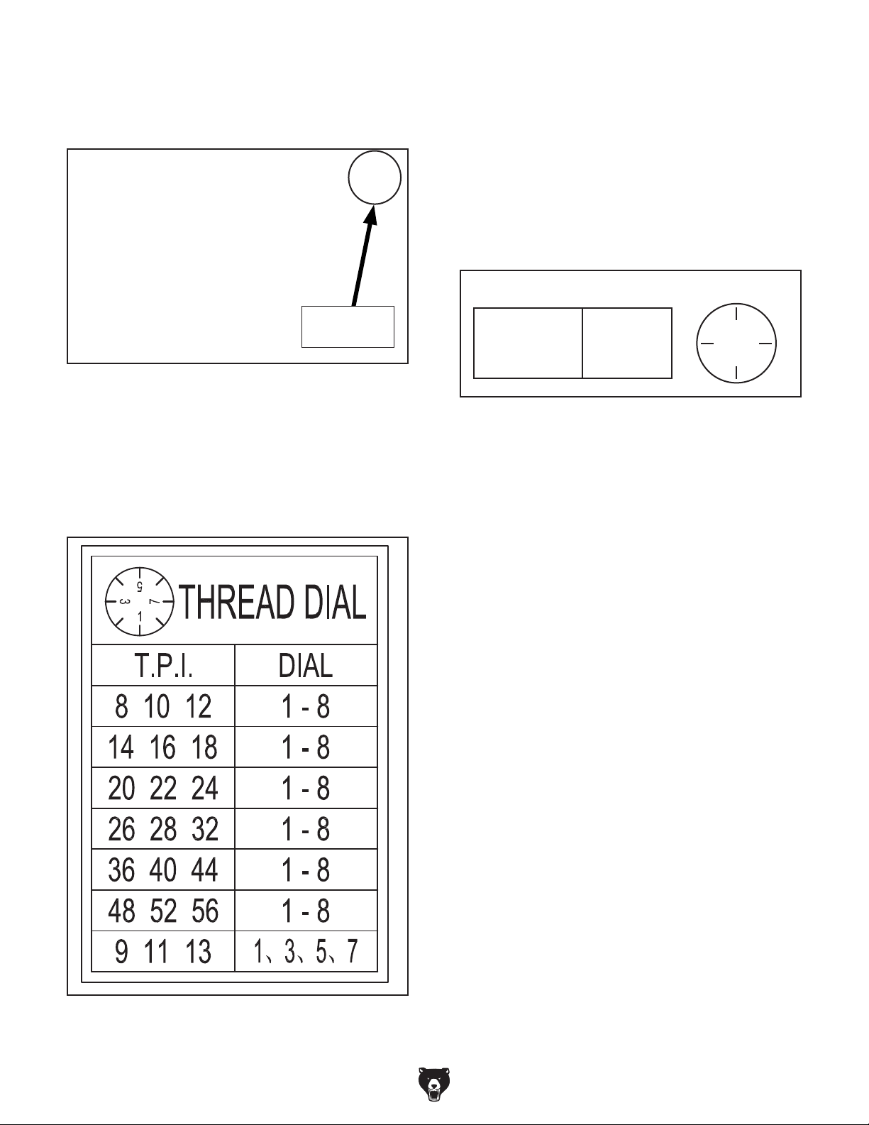
Thread Dial Chart
The thread dial chart is located on the backsplash,
as shown in Figure 81.
The following examples explain how to use
the thread dial and thread dial chart.
TPI Divisible by even number: Half-nut can be
engaged when thread dial is on any of the eight
marks.
TPI Divisible by odd number: Half-nut can only
be engaged on odd numbers (1, 3, 5, and 7) of the
dial (see Figure 83).
Thread Dial
Chart
Figure 81. Thread dial chart location.
To use the thread chart, find the TPI (threads per
inch) that you want to cut in the left column on the
thread dial chart (see Figure 82), then reference
the dial number to the right. The dial numbers
indicate when to engage the half nut for a specific
thread pitch as indicated by the thread dial.
TPI
9,11,13
Dial Number
Numbered
Positions
1, 3, 5, 7
Thread Dial
1
3
7
5
Figure 83. Example of an odd numbered inch
thread pitch.
-56-
Figure 82. Thread dial chart.
Model G0949G (Mfd. Since 01/22)
Page 59
ACCESSORIES
Installing unapproved accessories may
order online at www.grizzly.com or call 1-800-523-4777
SECTION 5: ACCESSORIES
cause machine to malfunction, resulting in
serious personal injury or machine damage.
To reduce this risk, only install accessories
recommended for this machine by Grizzly.
NOTICE
Refer to our website or latest catalog for
additional recommended accessories.
T23962—ISO 68 Moly-D Way Oil, 5 Gal.
T23963—ISO 32 Moly-D Machine Oil, 5 Gal.
Moly-D oils are some of the best we've found for
maintaining the critical components of machinery
because they tend to resist run-off and maintain
their lubricity under a variety of conditions—as
well as reduce chatter or slip. Buy in bulk and
save with 5-gallon quantities.
T23962 T23963
SBCE3450—How to Run a Lathe Book
First printed in 1907 by South Bend Lathe, this
56th edition is an exact reprint from 1966. Well
illustrated with vintage photos and drawings, this
128-page book is written specifically about the
care and operation of a metal lathe.
Figure 86. SBCE3450 South Bend Lathe~How
to Run a Lathe book.
H7617—High Pressure Oil Can, 5 Oz. With Flex
Nozzle
Whether you’re lubricating cutting tools or maintaining machinery in top operating condition, you’ll
appreciate this High Pressure Oil Can. The H7617
holds 5 ounces of oil and has a trigger activated,
high pressure pump.
Figure 84. ISO 68 and ISO 32 machine oil.
T26419 —Syn-O-Gen Multi-Purpose Grease
Syn-O-Gen Multi-purpose Synthetic Grease is formulated with 100% pure synthesized hydrocarbon
base stocks to impart its remarkable properties.
Figure 87. Model H7617 High-Pressure Oil Can
Figure 85. Model T26419 Syn-O-Gen Grease.
Model G0949G (Mfd. Since 01/22)
w/Flex Nozzle.
-57-
Page 60

order online at www.grizzly.com or call 1-800-523-4777
Basic Eye Protection
T32323—Woodturners Face Shield
T32401—EDGE Brazeau Safety Glasses, Clear
T32402—EDGE Khor G2 Safety Glasses, Tint
T32404—EDGE Mazeno Safety Glasses, Clear
T32323 T32401
T10439—4-Pc. Carbide Insert CCMT Boring
Bar Set
These right-hand indexable solid steel boring bars
1
⁄4" and 3⁄8", 80° diamond inserts and feature a
use
negative 7° end and side cutting angle. Includes
3
⁄8" x 6", 1⁄2 " x 7", 5⁄8" x 8", and 3⁄4" x 10" boring
bars. Set comes with Torx
®
wrenches and fitted
aluminum case with handle.
T32402
T32404
Figure 88. Assortment of basic eye protection.
T10295—7-Pc. Indexable-Carbide Turning Tool
Set
5
⁄8" 7-piece turning tool set is ideal for just
This
about any project. Supplied with right-hand and
left-hand turning/facing tool holders, the set is
complemented with one threading and cut-off
tool, too. Indexable inserts ensure cutting surfaces stay sharp.
Figure 90. T10439 Carbide Insert CCMT Boring
Bar Set.
G9849—Magnetic Base/Dial Indicator Combo
Magnetic base engages with the turn of a switch
and allows pinpoint adjustment. The dial indicator
features 0–1" travel and has a resolution of 0.001".
Set includes a molded case for protection and
convenience.
Figure 89. T10295 7-Pc. Indexable Carbide Tool
Set.
-58-
Figure 91. G9849 Magnetic base/dial indicator
combo.
Model G0949G (Mfd. Since 01/22)
Page 61
SECTION 6: MAINTENANCE
To reduce risk of shock or
accidental startup, always
disconnect machine from
power before adjustments,
Daily, After Operations
• Press the E-Stop button (to prevent accidental startup).
• Vacuum/clean all chips and swarf from bed,
slides.
• Wipe down all unpainted or machined sur-
maintenance, or service.
Schedule
faces with an oiled rag.
Every 50 Hours
• Lubricate end gears (Page 64).
For optimum performance from this machine, this
maintenance schedule must be strictly followed.
Ongoing
To minimize your risk of injury and maintain proper
machine operation, shut down the machine immediately if you ever observe any of the items below,
and fix the problem before continuing operations:
• Loose mounting bolts or fasteners.
• Worn, frayed, cracked, or damaged wires.
• Guards or covers removed.
• E-Stop button not working correctly or not
requiring you to reset it before starting the
machine again.
• Oil level not visible in the sight glasses.
• Damaged or malfunctioning components.
Daily, Before Operations
• Check/add headstock oil (Page 60).
• Check/add gearbox oil (Page 61).
• Check/add apron oil (Page 62).
• Add oil to the ball oilers (Page 63).
• Clean/lubricate the leadscrew (Page 63).
• Disengage the feed lever and feed selection
lever on the apron (to prevent crashes upon
startup).
• Ensure carriage lock bolt is loose.
Every 1000 Operating Hours
• Change the headstock oil (Page 60).
• Change the gearbox oil (Page 61).
• Change the apron oil (Page 62).
Annually
• Check/level bedway (Page 24).
Cleaning/Protecting
Because of its importance, we recommend that
the cleaning routine be planned into the workflow
schedule.
Typically, the easiest way to clean swarf from the
machine is to use a wet/dry shop vacuum that is
dedicated for this purpose. The small chips left
over after vacuuming can be wiped up with a
slightly oiled rag. Avoid using compressed air to
blow off chips, as this may drive them deeper into
the moving surfaces or cause sharp chips to fly
into your face or hands.
All unpainted and machined surfaces should be
wiped down daily to keep them rust free and in
top condition. This includes any surface that is
vulnerable to rust if left unprotected (especially
parts that are exposed to water soluble cutting
fluid). Use a quality ISO 68 way oil (see Page 57
for offerings from Grizzly) to prevent corrosion.
Model G0949G (Mfd. Since 01/22)
-59-
Page 62
Lubrication
Use the information in the charts below as a daily
guide for lubrication tasks. We recommend using
Grizzly T23962 (ISO 68) or T23963 (ISO 32) lubricants (see Accessories on Page 57) for most of
the lubrication tasks.
NOTICE
The recommended lubrication is based on
light-to-medium usage. Keeping in mind
that lubrication helps to protect the value
and operation of the lathe, these lubrication
tasks may need to be performed more frequently than recommended here, depending on usage.
Lubrication Frequency
Lubrication Task Frequency
Headstock Daily
Gearbox Daily
Apron Daily
Bedways Daily
Longitudinal Leadscrew Daily
Ball Oilers Daily
End Gears
Every 50
Hours
Page
Ref.
this
page
Lubrication Amount & Type
Lubrication Task Oil Type Amount
Headstock ISO 32
Gearbox ISO 68
Apron ISO 68
Bedways ISO 68
Longitudinal Leadscrew ISO 68
Ball Oilers ISO 32
End Gears NLGI #2
27 oz.
13.5 oz.
6.75 oz.
As
Needed
As
Needed
1–2
Squirts
Dab
on
61
62
63
63
63
64
Failure to follow reasonable lubrication
practices as instructed in this manual could
lead to premature failure of lathe components and will void the warranty.
Headstock
Oil Type .... Grizzly T23963 or ISO 32 Equivalent
Oil Amount
Check/Add Frequency
Change
The headstock gearing is lubricated by an oil bath
that distributes the lubricant with the motion of the
gears, much like an automotive manual transmission. Change the oil after the first 300 hours of
use, then every 1000 hours.
Checking Oil Level
The headstock reservoir has the proper amount of
oil when the oil level in the sight glass is approximately halfway. The oil sight glass is located on
the on the lower left side of the headstock, as
shown in Figure 92.
Headstock
Oil Sight
Glass
..........................................27 Ounces
................................. Daily
................. Every 1000 Operating Hours
Chuck
Items Needed Qty
Open-End Wrenches 8, 13, 14, 24mm
Two-Quart Catch Pan
Pump-Type Oil Can w/Plastic Cone Tip
Stiff Brush
Mineral Spirits
-60-
.......................................................... 1
.................................................... 1
........................................ 1
........1 Ea.
............ 1
Figure 92. Location of headstock oil sight glass.
Model G0949G (Mfd. Since 01/22)
Page 63
Adding Oil
The oil fill plug is located on top of the headstock,
as shown in Figure 93. The oil drain plug is
located on the side of the headstock, behind the
end gear cover.
Gearbox
Oil Type .... Grizzly T23962 or ISO 68 Equivalent
Oil Amount
Check/Add Frequency
Change
Checking Oil Level
The gearbox reservoir has the proper amount of
oil when the oil level in the sight glass (see Figure
94) is approximately halfway. The oil sight glass
is located below the feed rate selector near the
bottom of the control panel.
.......................................13.5 Ounces
................................. Daily
.................. Every 1000 Operating Hours
Center
Fill
Plug
Figure 93. Headstock fill and drain plugs.
To change headstock oil:
1. DISCONNECT MACHINE FROM POWER!
2. Open end-gear cover.
3. Remove V-belts so that oil does not get
on them, necessitating their replacement
(refer to Replacing V-Belts on Page 73 for
detailed instructions).
Remove fill plug from top of headstock (see
4.
Figure 93).
Place two-quart catch pan under headstock
5.
drain plug (see Figure 93), then remove
drain plug.
Drain
Plug
Gearbox Oil
Sight Glass
Drain Plug
Figure 94. Location of gearbox oil sight glass
and drain plug.
Adding Oil
The oil fill plug is located on the right side of
the gearbox, behind the gearbox oil cover (see
Figure 95). Change the gearbox oil after the first
300 hours of use, then after every 1000 hours of
use.
When headstock reservoir is empty, replace
6.
drain plug and clean away any spilled oil.
Fill headstock reservoir until oil level is
7.
approximately halfway in sight glass.
Replace and re-tension V-belts (refer to
8.
Replacing V-Belts on Page 73), then close
end-gear cover before re-connecting lathe to
power.
Model G0949G (Mfd. Since 01/22)
Gearbox
Oil
Cover
Figure 95. Location of gearbox oil cover.
-61-
Page 64
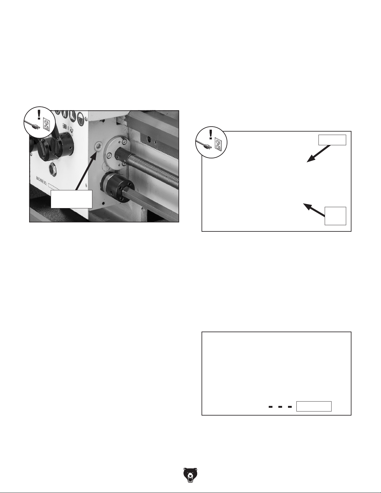
To change gearbox oil:
1.
DISCONNECT MACHINE FROM POWER!
2. Remove gearbox oil cover (see Figure 95 on
Page 60).
Apron
Oil Type .... Grizzly T23962 or ISO 68 Equivalent
Oil Amount
Check/Add Frequency
Change
.......................................6.75 Ounces
................................. Daily
.................. Every 1000 Operating Hours
Remove fill plug from side of gearbox (see
3.
Figure 96).
Gearbox Oil
Fill Plug
Figure 96. Gearbox fill plug.
4. Remove end gear cover.
5. Remove "L", Z3, and Z4 gears, then place a
two-quart catch pan under drain plug.
Remove drain plug (see Figure 94 on Page
6.
60).
When reservoir is empty, replace drain plug
7.
and clean up any spilled oil.
Checking Oil Level
The apron oil sight glass is on the front of the
apron, as shown in Figure 97. Maintain the oil
volume so that the level is approximately halfway
in the sight glass.
Fill Plug
Sight
Glass
Figure 97. Location of apron oil sight glass.
Changing Oil & Flushing Reservoir
Small metal particles may accumulate at the bottom of the reservoir with normal use. Therefore,
to keep the reservoir clean, drain and flush it after
the first 300 hours, then after every 1000 hours.
Place a catch pan under the apron drain plug
shown in Figure 98, then remove the fill plug and
drain plug, and empty the reservoir.
Fill gearbox reservoir until oil level is approxi-
8.
mately halfway in sight glass (see Page 61
for gearbox oil capacity).
Replace oil gearbox fill plug and gearbox oil
9.
cover.
Install "L", Z3, and Z4 gears, then install end
10.
gear cover.
-62-
Drain Plug
Figure 98. Location of apron drain plug.
Flush the reservoir by pouring a small amount of
clean oil into the fill hole and allowing it to drain
out the bottom. Replace the drain plug, add oil as
previously described, then re-install the fill plug.
Model G0949G (Mfd. Since 01/22)
Page 65
Bedways
Oil Type ................ T23962 or ISO 68 Equivalent
Oil Amount
Lubrication Frequency
......................................... As Needed
................................. Daily
Ball Oilers
Oil Typ e .... Grizzly T23963 or ISO 32 Equivalent
Oil Amount
Lubrication Frequency
......................................1 or 2 Squirts
................................. Daily
Before lubricating the bedways (see Figure 99),
clean them with mineral spirits. Apply a thin coat
of oil along the length of the bedway. Move the
steady rest, carriage, and tailstock to access the
entire length of the bedways. If the lathe is in a
moist or dirty environment, increase the lubrication frequency.
Bedways
Figure 99. Bedways.
This lathe has 16 ball oilers that should be oiled
on a daily basis before beginning operation. Refer
to Figures 100–103 for their locations.
Ball Oilers
Proper lubrication of ball oilers is done with a
pump-type oil can that has a plastic or rubberized cone tip. We do not recommend using metal
needle or lance tips, as they can push the ball too
far into the oiler, break the spring seat, and lodge
the ball in the oil galley.
Lubricate the ball oilers before and after machine
use, and more frequently under heavy use. When
lubricating ball oilers, first clean the outside surface to remove any dust or grime. Push the rubber or plastic tip of the oil can nozzle against the
ball oiler to create a hydraulic seal, then pump the
oil can once or twice. If you see sludge and contaminants coming out of the lubrication area, keep
pumping the oil can until the oil runs clear. When
finished, wipe away any excess oil.
Longitudinal Leadscrew
Oil Type .... Grizzly T23962 or ISO 68 Equivalent
Oil Amount
Lubrication Frequency
Before lubricating the leadscrew (see Figure 102
on Page 64), clean it first with mineral spirits.
A stiff brush works well to help clean out the
threads. Make sure to move the carriage out of
the way, so you can clean the entire length of the
leadscrew.
Apply a thin coat of oil along the length of the
leadscrew. Use a stiff brush to make sure the oil
is applied evenly and down into the threads.
Note: In some environments, abrasive material
can become caught in the leadscrew lubricant and
drawn into the half nut. In this case, lubricate the
leadscrew with a quality dry lubricant.
......................................... As Needed
................................. Daily
A. Saddle, cross-slide, compound rest
B. Handwheels
. Leadscrew
C
D. Feed rod
E. Tailstock
A
Figure 100. Saddle, slide and rest ball oilers.
Model G0949G (Mfd. Since 01/22)
-63-
Page 66
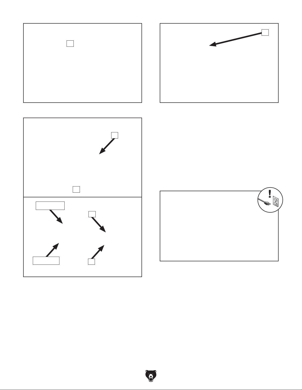
E
B
Figure 101. Handwheel ball oilers.
D
Leadscrew
C
Figure 103. Tailstock ball oiler.
End Gears
Grease Type ........ T26419 or NLGI#2 Equivalent
C
Lubrication
The end gears, shown in Figure 104, should
always have a thin coat of heavy grease to
minimize corrosion, noise, and wear. Wipe away
excess grease that could be thrown onto the
V-belt and reduce optimal power transmission
from the motor.
................. Every 50 Operating Hours
Feed Rod
Figure 102. Leadscrew/feed rod ball oilers.
-64-
D
Figure 104. End gears.
Handling & Care
Make sure to clean and lubricate any gears you
install or change. Be very careful during handling
and storage—the grease coating on the gears will
easily pickup dirt or debris, which can then spread
to the other gears and increase the rate of wear.
Make sure the end-gear cover remains closed
whenever possible to keep the gears free of dust
or debris from the outside environment.
Model G0949G (Mfd. Since 01/22)
Page 67

Lubricating
1. DISCONNECT MACHINE FROM POWER!
Remove end-gear cover and remove all end
2.
gears shown in Figure 104 on Page 64.
Clean end gears thoroughly with mineral spir-
3.
its to remove old grease. Use a small brush if
necessary to clean between teeth.
Clean shafts, and wipe away any grease
4.
splatters in the vicinity and on inside of the
end-gear cover.
Using clean brush, apply thin layer of grease
5.
on gears. Make sure to get grease between
gear teeth, but do not fill teeth valleys.
Install end gears and mesh them together
6.
with an approximate 0.002"–0.004" backlash.
Once gears are meshed together, apply
small dab of grease between them where
they mesh together—this grease will be distributed when gears rotate and recoat any
areas scraped off during installation.
3. Thoroughly clean all unpainted, bare metal
surfaces, then apply a liberal coat of way
oil, heavy grease, or rust preventative. Take
care to ensure these surfaces are completely
covered but that rust preventative or grease
is kept off of painted surfaces.
. Lubricate machine as outlined in the lubri-
4
cation section. Be sure to use an oil can to
purge all ball oilers and oil passages with
fresh oil.
Place a few moisture absorbing desiccant
5.
packs inside of electrical box.
Loosen or remove V-belt so it does not
6.
become stretched during the storage period.
(Be sure to place a maintenance note near
power button as a reminder that belt has
been loosened or removed).
Cover lathe and place it in a dry area that is
7.
out of direct sunlight and away from hazardous fumes, paint, solvents, or gas. Fumes
and sunlight can bleach or discolor paint.
7. Re-install end-gear cover before reconnecting lathe to power.
Machine Storage
To prevent the development of rust and corrosion,
the lathe must be properly prepared if it will be
stored for a long period of time. Doing this will
ensure the lathe remains in good condition for
later use.
Preparing Lathe for Storage
1. Run lathe and bring all reservoirs to operating
temperature, then drain and refill them with
clean oil.
DISCONNECT MACHINE FROM POWER!
2.
Every few months, rotate by hand all gear-
8.
driven components a few times in several
gear selections. This will keep bearings,
bushings, gears, and shafts well lubricated
and protected from corrosion—especially
during the winter months.
Slide carriage, tailstock, and steady rest
9.
down lathe bed to make sure that way spotting is not beginning to occur.
Bringing Lathe Out of Storage
1. Re-install V-belt and tension it (refer to Page
73) if you removed it for storage purposes.
Remove moisture-absorbing desiccant packs
2.
from electrical box.
Repeat Test Run and Spindle Break-In pro-
3.
cedures, beginning on Pages 25 & 28.
Model G0949G (Mfd. Since 01/22)
-65-
Page 68
Review the troubleshooting procedures in this section if a problem develops with your machine. If you need
the
serial number and manufacture date of your machine before calling.
SECTION 7: SERVICE
replacement parts or additional help with a procedure, call our Technical Support. Note: Please gather
Troubleshooting
Motor & Electrical
Symptom Possible Cause Possible Solution
Machine does
not start, or
power supply
breaker
immediately
trips after
startup.
1. Master power switch in OFF position.
2. E-Stop button depressed/at fault.
3. Blown fuse.
4. Incorrect power supply voltage or circuit size.
5. Motor speed potentiometer at fault.
6. Power supply circuit breaker tripped or fuse
blown.
7. Motor wires connected incorrectly.
1. Turn master power switch to ON position.
2. Rotate E-Stop button head to reset. Replace if at fault.
3. Replace fuse/ensure no shorts.
4. Ensure correct power supply voltage and circuit size.
5. Test/replace if at fault.
6. Ensure circuit is free of shorts. Reset circuit breaker or
replace fuse.
7. Correct motor wiring connections (Page 83).
Machine
stalls or is
underpowered.
8. Wiring broken, disconnected, or corroded.
9. START button at fault.
10. Circuit board at fault.
11. Motor or motor bearings at fault.
1. Feed rate/cutting speed too fast.
2. Improper tooling or workpiece material.
3. Gearbox at fault.
4. Motor circuit board at fault.
5. Motor speed potentiometer at fault.
6. Belt(s) slipping/pulley(s) misaligned.
7. Motor wired incorrectly.
8. Pulley slipping on shaft.
9. Machine undersized for task.
10. Motor overheated.
11. Extension cord too long.
12. Motor or motor bearings at fault.
8. Fix broken wires or disconnected/corroded
connections.
9. Replace START button.
10. Inspect/replace if at fault.
11. Replace motor.
1. Decrease feed rate/cutting speed.
2. Use appropriate tooling and/or workpiece material.
3. Select appropriate gear ratio; replace broken or
slipping gears.
4. Inspect and replace if at fault.
5. Test and replace if at fault.
6. Clean/tension/replace belt(s) (Page 73); ensure
pulleys are aligned.
7. Wire motor correctly (Page 83).
8. Tighten/replace loose pulley/shaft.
9. Use sharp bits/chisels at correct angle; reduce feed
rate/depth of cut; use cutting fluid if possible.
10. Clean motor, let cool, and reduce workload.
11. Move machine closer to power supply; use shorter
extension cord.
12. Replace motor.
-66-
Model G0949G (Mfd. Since 01/22)
Page 69

Operation
Symptom Possible Cause Possible Solution
Machine has
vibration or
noisy operation.
Entire machine
vibrates upon
startup and
while running.
Bad surface
finish.
Tapered tool
difficult to
remove from
tailstock quill.
Tapered tool
will not lock in
quill.
Cross slide,
compound rest,
or carriage feed
has sloppy
operation.
Chuck jaws
will not move
or do not move
easily.
1. Motor or component loose.
2. Lathe Incorrectly mounted on stand.
3. V-belt(s) worn, loose, pulleys misaligned, or
belt slapping cover.
4. Pulley loose.
5. Motor mount loose/broken.
6. Spindle loose, improperly installed or
damaged.
7. Bit chattering.
8. Workpiece or chuck at fault.
9. Motor bearings at fault.
10. Gearbox at fault.
1. Workpiece unbalanced.
2. Workpiece hitting stationary object.
3. Loose or damaged V-belt(s).
4. V-belt pulleys not properly aligned.
5. Worn/broken gear or bad bearing.
6. Spindle bearings at fault.
1. Incorrect spindle speed or feed rate.
2. Dull tooling or wrong tool selection.
3. Workpiece deflecting.
4. Excessive play in gibs.
5. Material building up on cutting tool.
6. Bearing preload needs to be adjusted.
7. Belts bad.
8. Spindle bearings at fault.
9. Tool height not at center line.
1. Quill not fully retracted into tailstock. 1. Rotate quill handwheel until it forces tapered tool out
1. Debris not removed from tool taper before
inserting into quill.
1. Gibs are out of adjustment.
2. Handwheel loose or has excessive backlash.
3. Leadscrew mechanism worn or out of
adjustment.
1. Chips lodged in jaws or scroll plate.
2. Dent/ridge in jaw slot of chuck body.
1. Replace damaged or missing bolts/nuts or tighten if
loose.
2. Adjust feet, shim, or tighten mounting hardware.
3. Inspect/replace belt with a new belt (Page 73). Realign pulleys if necessary.
4. Secure pulley on shaft.
5. Tighten/replace.
6. Tighten loose spindle, re-install spindle ensuring
mating surfaces are clean, replace spindle if damaged.
7. Replace/sharpen bit; index bit to workpiece; use
correct feed rate and cutting RPM.
8. Center workpiece in chuck or face plate; replace
defective chuck.
9. Test by rotating shaft; rotational grinding/loose shaft
requires bearing replacement.
10. Rebuild gearbox for bad gear(s)/bearing(s).
1. Re-install workpiece as centered with spindle bore as
possible.
2. Stop lathe immediately and correct interference
problem.
3. Re-tension/replace V-belt(s) as necessary (Page 73).
4. Align V-belt pulleys.
5. Replace broken gear or bearing.
6. Reset spindle bearing preload or replace spindle
bearings.
1. Use correct spindle speed and feed rate.
2. Sharpen tooling; use correct tool for operation.
3. Change setup to properly support workpiece.
4. Tighten gibs (Page 70).
5. Use coolant on tool and workpiece during operation.
6. Adjust bearing preload (Page 76).
7. Replace belts (Page 73).
8. Replace spindle bearings.
9. Adjust tool height to center line.
of quill.
1. Remove debris from tapered tool before re-inserting
into quill.
1. Adjust gibs (Page 70).
2. Tighten handwheel fasteners or adjust handwheel
backlash to a minimum (Page 69).
3. Adjust leadscrew to remove end play (Page 72).
1. Remove jaws, clean and lubricate scroll plate, then
re-install jaws.
2. Stone or file off high spot in jaw slots.
Model G0949G (Mfd. Since 01/22)
-67-
Page 70

Symptom Possible Cause Possible Solution
Spindle lacks
turning power
or starts up
slowly.
Workpiece is
tapered.
Gear change
levers will
not shift into
position.
Cross slide,
compound,
or carriage
handwheels
hard to move.
Cutting tool
or machine
components
vibrate
excessively
during cutting.
Carriage will
not feed or hard
to move.
Workpiece slips
in chuck.
1. Belts slipping. 1. Tighten belts (Page 73); inspect for oil/grease on belts
and clean/replace as necessary.
1. Spindle and tailstock centers not properly
aligned with each other.
2. Lathe bed twisted.
1. Gears not aligned inside headstock/QuickChange gearbox.
1. Ways dry and in need of lubricant.
2. Ways loaded with shavings, dust, or grime.
3. Gibs are too tight.
4. Backlash setting too tight.
1. Tool holder not tight enough.
2. Cutting tool sticks too far out of tool holder;
lacks support.
3. Workpiece deflecting.
4. Workpiece unbalanced.
5. Gibs out of adjustment.
6. Cutting tool dull.
7. Spindle speed or feed rate incorrect.
1. Gears not all engaged.
2. Half nut lever engaged.
3. Carriage lock tightened down.
4. Chips loaded up on ways.
5. Ways dry and in need of lubrication.
6. Gibs too tight.
7. Shear pin broken.
1. Cutting pressure/feed rate too high.
2. Jaws worn or not installed properly.
1. Re-align tailstock to headstock spindle centerline
(Page 39).
2. Level lathe (Page 24).
1. Rotate spindle by hand with light pressure on the
lever until gear falls into place.
1. Lubricate ways/ball oilers (Page 63).
2. Remove gibs, clean ways, lubricate, re-install, and readjust.
3. Loosen gibs slightly (Page 70), and lubricate ways.
4. Slightly loosen backlash setting (Page 69).
1. Tighten tool holder.
2. Re-install cutting tool so no more than
length sticks out of tool holder.
3. Use steady or follow rest (Pages 43–44).
4. Balance workpiece.
5. Adjust gibs (Page 70).
6. Replace or resharpen cutting tool.
7. Use recommended spindle speed (Page 48) and feed
rate (Page 49).
1. Engage gears using gear levers.
2. Disengage half nut lever.
3. Make sure carriage lock is fully released.
4. Frequently clear away chips that load up during
turning operations.
5. Lubricate ways/ball oilers (Page 63).
6. Loosen gib screw(s) slightly (Page 70).
7. Replace gears/shear pin (Page 74).
1. Reduce cutting force.
2. Remove/re-install properly; turn jaws with cutting tool
so they are concentric; replace jaws as matched set or
chuck.
1
⁄3 of total
-68-
Model G0949G (Mfd. Since 01/22)
Page 71
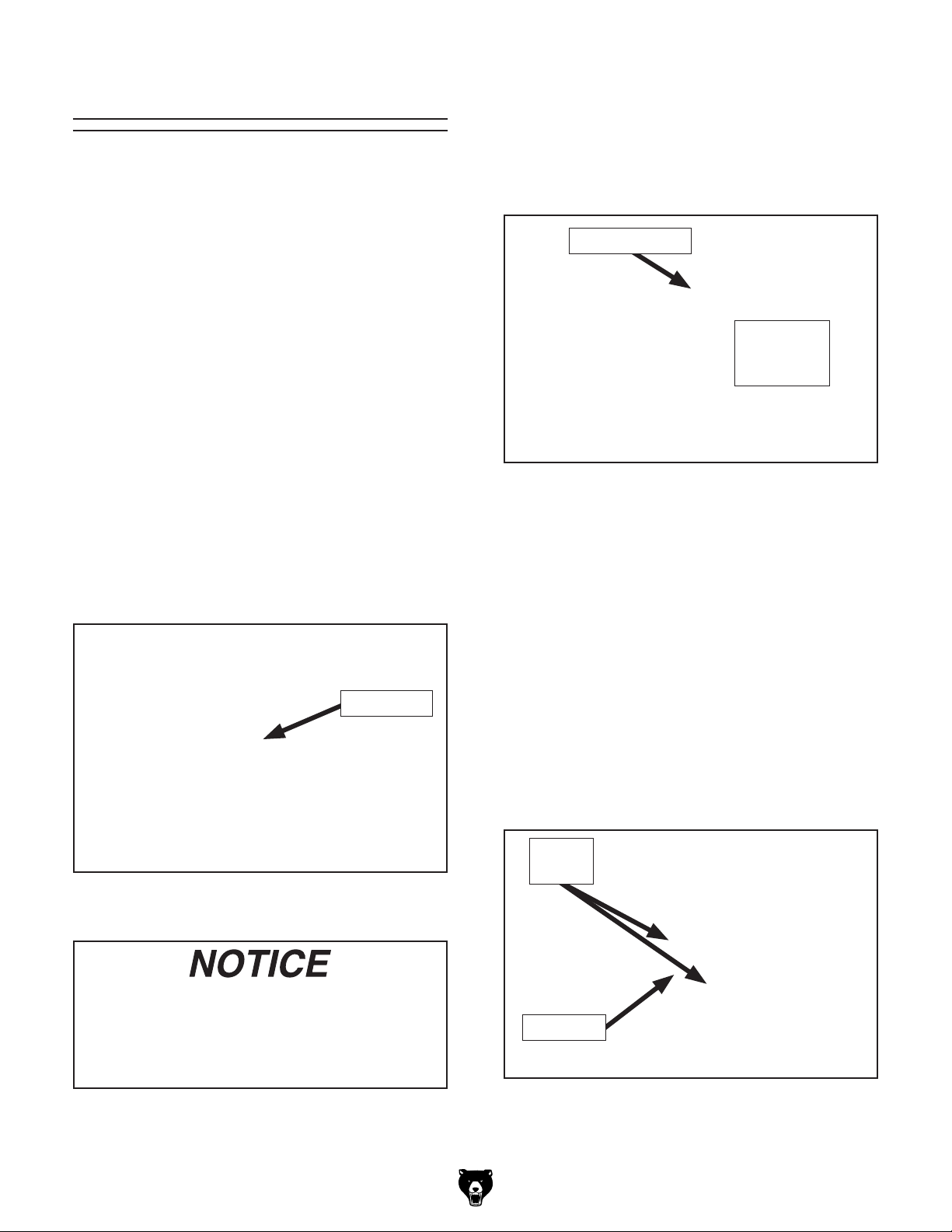
Backlash Adjustment
3. Rotate cross slide handwheel clockwise to
feed leadscrew nut out from under cross
slide, as shown in Figure 106.
Backlash is the amount of play in a leadscrew and
can be felt as the free play in a handwheel when
changing direction of rotation. The amount of the
backlash can be viewed on the handwheel graduated dial.
When adjusting backlash, tighten the components
enough to remove backlash, but not so much that
the components bind the leadscrew, making it
hard to turn. Overtightening will cause excessive
wear to the sliding block and leadscrew.
Tools Needed Qty
Hex Wrenches 2, 5, 6mm ............................1 Ea.
Punch Pin 2mm
................................................ 1
Cross Slide Backlash
1. Feed cross slide toward operator until it
reaches end of its travel.
Remove cap screw that secures cross slide
2.
leadscrew nut (see Figure 105).
Tighten backlash adjustment cap screw
4.
shown in Figure 106 in small increments.
Leadscrew Nut
Backlash
Adjustment
Cap Screw
Figure 106. Cross slide leadscrew nut.
5. Hold leadscrew nut and test after each
adjustment by rotating handwheel back-andforth until backlash amount is approximately
0.002"–0.004".
Cap Screw
Figure 105. Location of cap screw that secures
leadscrew nut.
Reducing backlash to less than 0.002" is
impractical and can lead to accelerated wear
of the wedge, nut, and leadscrew. Avoid the
temptation to overtighten the backlash set
screw while adjusting.
Feed leadscrew nut back under cross slide
6.
and replace cap screw removed in Step 2.
Compound Rest Backlash
1. Turn compound rest handwheel counter-
clockwise several turns.
Loosen set screws on compound rest face-
2.
plate several turns (see Figure 107).
Set
Screws
Faceplate
Figure 107. Compound rest backlash
adjustments.
Model G0949G (Mfd. Since 01/22)
-69-
Page 72
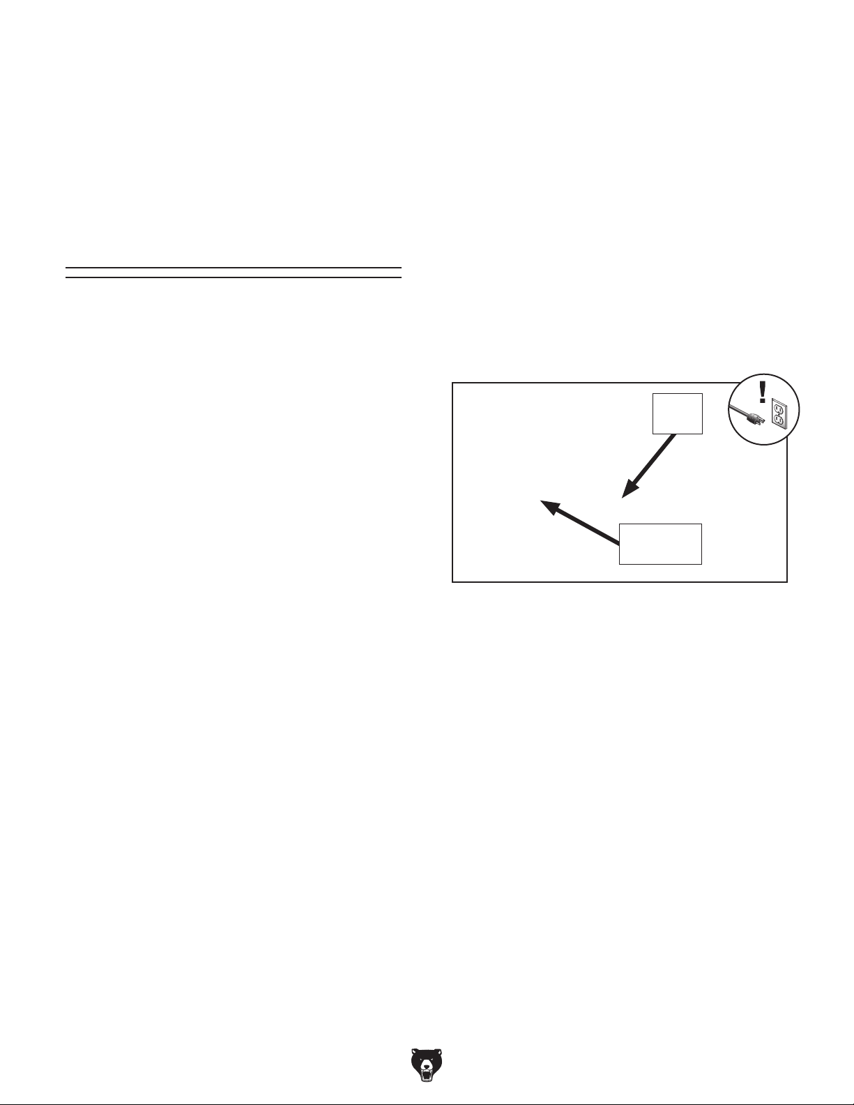
3. Use punch pin to loosen faceplate and adjust
it until backlash is approximately 0.002"–
0.004", as indicated on graduated dial.
Secure setting with set screws.
4.
5. Repeat adjustments above if necessary.
Gib Adjustment
The goal of adjusting the gib screws is to remove
sloppiness or "play" from the ways without overadjusting them to the point where they become
stiff and difficult to move.
Tools Needed Qty
Phillips Head Screwdriver #2 ............................ 1
Hex Wrenches 3, 6mm
Open-End Wrench 10mm
...................................... 1
.................................. 1
Cross Slide Gib
Make sure the bedways and leadscrew have been
cleaned and lubricated before any adjustments.
Refer to Lubrication on Page 60 for instructions
and lubricant specifications.
To adjust cross slide gib:
1. DISCONNECT MACHINE FROM POWER!
Loosen locking set screw (see Figure 108).
2.
In general, loose gibs cause poor finishes and
tool chatter; however, over-tightened gibs cause
premature wear and make it difficult to turn the
handwheels.
The cross-slide and compound slide on this lathe
each use a long steel wedge called a gib that is
positioned between the component and its dovetailed-ways. At the end of each gib is a gib screw,
which moves and holds the gib. Depending upon
which direction the gib moves, the space between
the sliding ways increases or decreases to control
the rigidity of the cross slide and compound slide.
Before adjusting the gibs, loosen the locks for
the device so that the gibs can freely slide during
adjustment, then lubricate the ways.
The gib adjustment process usually requires
some trial-and-error. Repeat the adjustment process as necessary until you find the best balance
between loose and stiff movement. Most machinists find that the ideal gib adjustment is one where
a small amount of drag or resistance is present,
yet the handwheels are still easy to move.
Set
Screw
Gib Screw
(1 of 2)
Figure 108. Cross slide gib components.
3. Adjust gib screws as follows:
— To increase slide tension, loosen rear gib
screw
1
— To decrease slide tension, loosen front gib
screw 1⁄8 turn, and tighten rear gib screw 1⁄8
turn.
After each adjustment, use cross slide
4.
handwheel to test cross slide movement.
⁄8 turn.
1
⁄8 turn, and tighten front gib screw
-70 -
Repeat Steps 3–4 until cross slide move-
5.
ment is acceptable.
Model G0949G (Mfd. Since 01/22)
Page 73
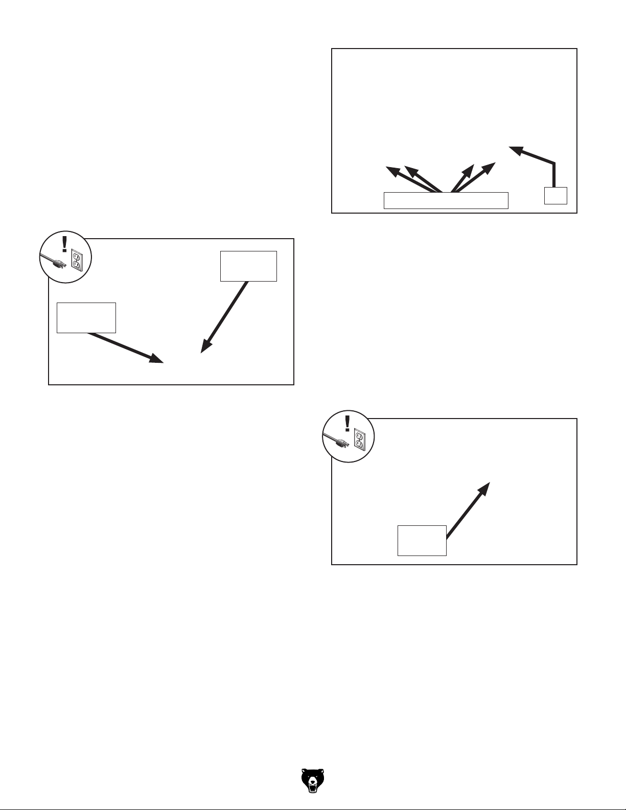
Compound Rest Gib
The compound rest gib is located on the bottom of
the back edge of the compound rest (see Figure
109). This gib is a wedge-shaped plate. The gib
pressure is applied by two set screws.
When adjusting the compound rest be aware
directions to increase or decrease the tension are
reversed from cross slide gib.
1. DISCONNECT MACHINE FROM POWER!
Loosen locking set screw (see Figure 109).
2.
Locking
Set Screw
Gib Screw
(1 of 2)
Figure 109. Compound rest gib components.
3. Adjust gib screws as follows:
— To increase slide tension, loosen rear gib
screw 1⁄8 turn, and tighten front gib screw
1
⁄8 turn.
Set Screws & Jam Nuts
Figure 110. Saddle gib components.
Tools Needed Qty
Open-End Wrenches 7, 10mm ....................1 Ea.
To adjust saddle gib:
DISCONNECT MACHINE FROM POWER!
1.
Clean and lubricate lathe bedways (refer to
2.
Page 63).
If carriage lock (see Figure 111) is tight,
3.
loosen it two turns.
Gib
— To decrease slide tension, loosen front gib
screw 1⁄8 turn, and tighten rear gib screw 1⁄8
turn.
After each adjustment, use compound rest
4.
handwheel to test compound rest movement.
Repeat Steps 3–4 until compound rest move-
5.
ment is acceptable.
Saddle Gib
The saddle gib is located on the bottom of the
back edge of the cross slide (see Figure 110).
This gib is designed differently than the cross or
compound slide gibs. Instead of being a wedgeshaped plate, it is a flat bar. The gib pressure is
applied by four set screws. Jam nuts secure these
set screws in place, so they will not loosen during
operation.
Model G0949G (Mfd. Since 01/22)
Carriage
Lock
Figure 111. Location of carriage lock.
To access saddle gib, remove backsplash.
4.
5. Loosen the hex nuts on four set screws
shown in Figure 110, and adjust set screws
same amount as follows:
— To tighten carriage gib, tighten set screw
in equal amounts.
— To loosen gib, loosen set screws in equal
amounts.
-71-
Page 74
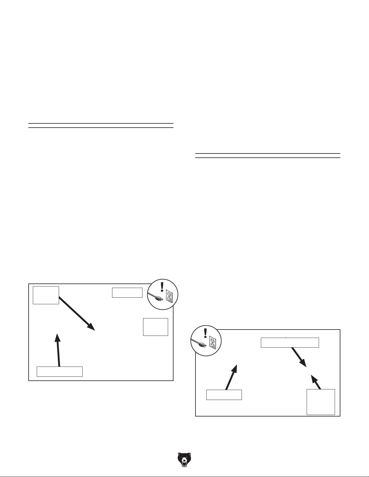
Move carriage back and forth and repeat
6.
adjustments as necessary until gib pressure
is acceptable.
Hold set screws in place and tighten hex
7.
nuts.
6. Move carriage handwheel until half nut can
fully close, then open/close half nut several
times and notice how it feels. Half nut is correctly adjusted when you feel a slight drag
while opening and closing it. It should not feel
too stiff or too loose.
Re-install backsplash.
8.
Half Nut Adjustment
The half-nut mechanism can be adjusted if it
becomes loose from wear. The half nut is mounted in ways with a gib exerting pressure between
components to reduce sloppy movement. The
half-nut gib is a flat, bar-type gib, similar to the
saddle gib, and is tensioned with two set screws.
Tools Needed
Hex Wrenches 4, 5, 13mm
To adjust half nut:
DISCONNECT MACHINE FROM POWER!
1.
Disengage half nut and remove thread dial.
2.
Qty
..........................1 Ea.
Repeat Steps 3–5, if necessary, until you
7.
are satisfied with half nut adjustment, then
re-install thread dial.
Leadscrew End-Play
Adjustment
After a period of time, you may find that the
leadscrew develops excessive end play. This
lathe is designed so that end play can be removed
with a simple adjustment.
Tool Needed
Spanner Wrench................................................ 1
To remove leadscrew end play:
DISCONNECT MACHINE FROM POWER!
1.
Qty
Loosen hex nuts on set screws shown in
3.
Figure 112.
Thread
Dial
Half Nut Lever
Figure 112. Half-nut gib set screws.
4.
Slide gib plate inward to desired amount.
Tighten each set screw approximately 1⁄8 of a
5.
turn, then re-tighten hex nuts without moving
set screws.
Gib Plate
Set
Screws
Loosen outer spanner nut (see Figure 113).
2.
Place spanner wrench on end of leadscrew.
3.
4. Rotate carriage handwheel to move carriage
toward tailstock, then tighten inner spanner
nut (see Figure 113) until there is 0.001"–
0.002" of end play.
Inner Spanner Nut
Leadscrew
Figure 113. Leadscrew and spanner nuts.
5. Tighten outer spanner nut until it is snug
against inner spanner nut to secure setting.
Outer
Spanner
Nut
-72-
Model G0949G (Mfd. Since 01/22)
Page 75
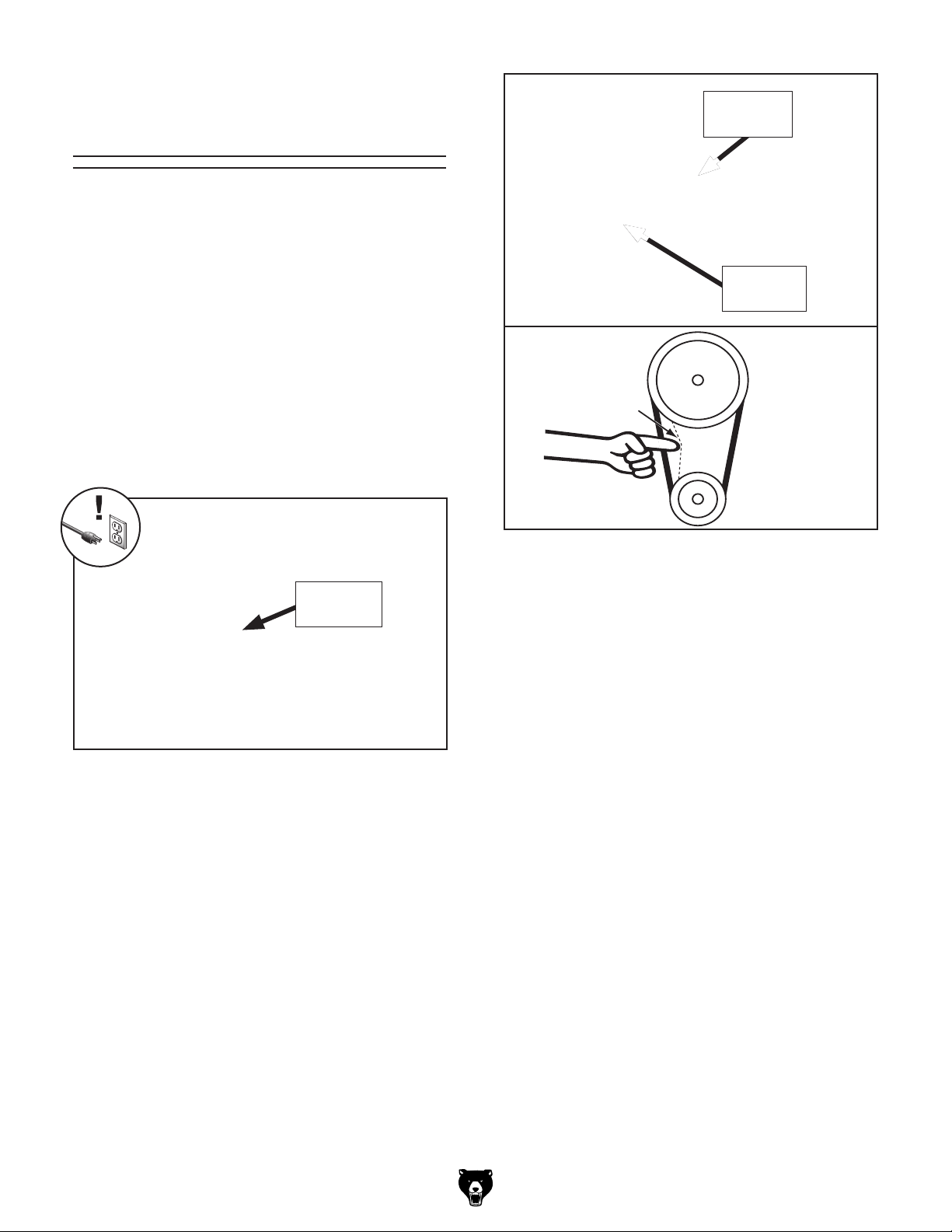
V-Belt Tension &
Pulley
Deflection
Pulley
Replacement
V-belts stretch and wear with use, so check tension after the first three months and then every
six months to ensure optimal power transmission.
Replace all V-belts as a matched set if any of
them show signs of glazing, fraying, or cracking.
Tools Needed Qty
Flat Head Screwdriver ¼" .................................. 1
Open-End Wrench 10mm
Tensioning V-Belt
DISCONNECT MACHINE FROM POWER!
1.
2. Remove end gear cover (see Figure 114).
.................................. 1
Tensioner
Bolt
Belt
Tensioner
(3/4")
Figure 115. Adjusting V-belt tension.
End-Gear
Cover
Figure 114. End-gear cover location.
3. Loosen tensioner bolt (see Figure 115).
Push tensioner against V-belt to tension it,
4.
then secure tensioner (see Figure 115).
Check belt tension: The belt is correctly
5.
tensioned when there is approximately 3⁄4"
deflection when it is pushed with moderate
pressure (see Figure 115). If there is more
3
⁄4" when belt is pushed, loosen tensioner
than
bolt, adjust belt tension, then tighten tensioner
bolt.
6. Secure end gear cover.
Replacing V-Belt
1. DISCONNECT MACHINE FROM POWER!
Remove end gear cover (see Figure 114).
2.
Loosen tensioner lock bolt, pivot tensioner to
3.
right and secure it temporarily, then remove
V-belt (see Figure 115).
4. Install new V-belt.
Tension V-belt.
5.
Re-install end gear cover.
6.
Model G0949G (Mfd. Since 01/22)
-73 -
Page 76
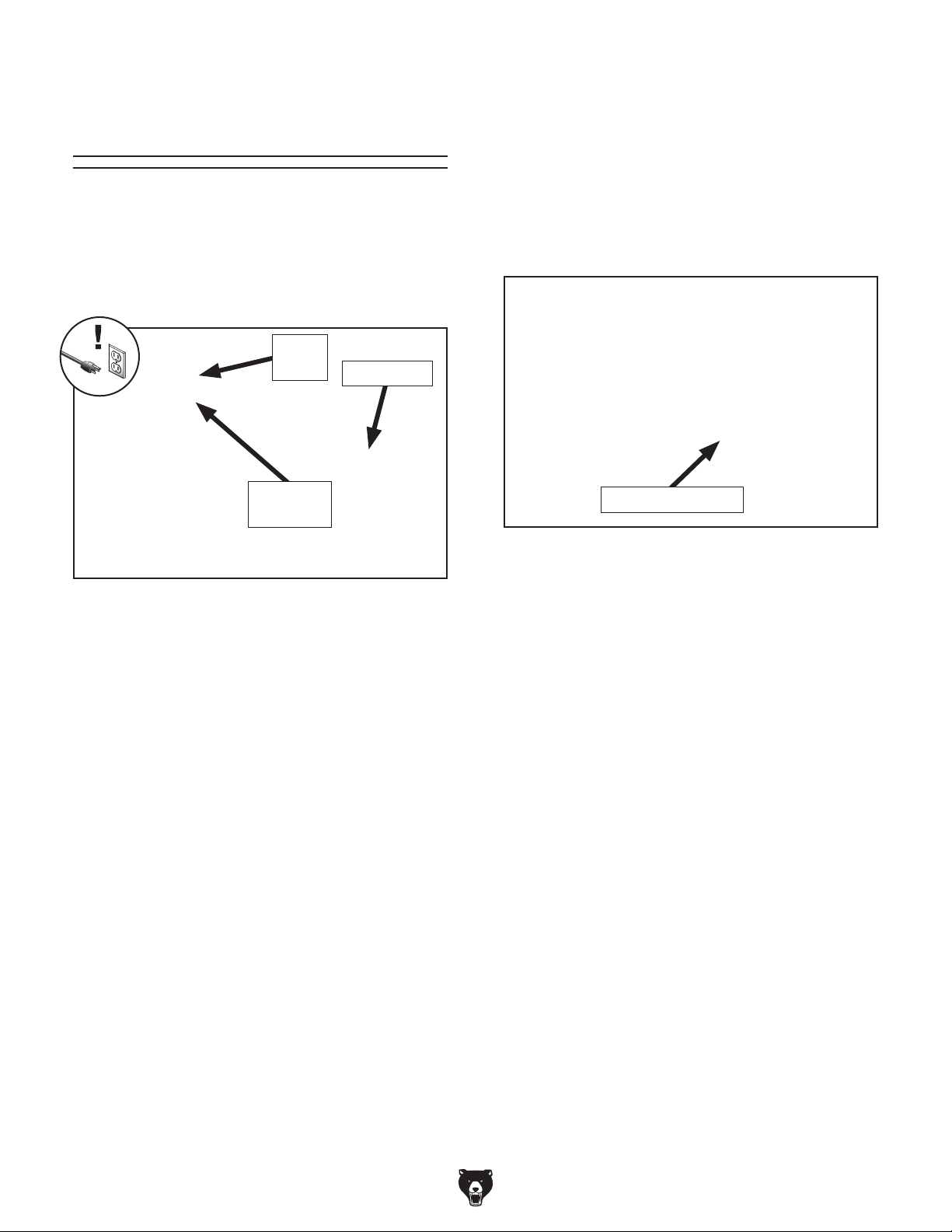
Leadscrew Shear Pin
Replacement
To replace leadscrew shear pin:
DISCONNECT MACHINE FROM POWER!
1.
2. Place quick-change gear levers in neutral.
A straight 5 x 20mm brass shear pin (see Figure
116) holds the leadscrew and the drive hub
together. The pin is designed to break and disengage the power transfer to the leadscrew to help
protect more expensive lathe components in the
case of a carriage crash or the lathe is overloaded.
Drive
Collar
Brass
Shear Pin
Figure 116. Leadscrew shear pin.
Tools Needed Qty
Hammer ............................................................. 1
Dowel Punch
Brass Shear Pin (#P0949G274)
3
⁄16" ............................................... 1
Leadscrew
Leadscrew
........................ 1
Disengage half-nut lever and move FWD/
3.
REV switch to "0" (see Figure 117) so
leadscrew can be rotated by hand.
FWD/REV Switch
Figure 117. FWD/REV switch set to "0".
4. Rotate leadscrew so shear pin is facing up
and down. If drive collar rotates independently of leadscrew, then rotate collar so shear
pin holes align with those in leadscrew.
Use punch and hammer to drive out pieces of
5.
old shear pin.
-74 -
Make sure holes in collar and leadscrew are
6.
aligned, then tap new shear pin completely
through holes in collar and leadscrew.
Model G0949G (Mfd. Since 01/22)
Page 77
Feed Clutch
Tool Needed Qty
Hex Wrench 4mm .............................................. 1
Adjustment
This lathe is equipped with a feed rod clutch,
shown in Figure 118, that connects the feed drive
hub with the feed rod through a set of springloaded ball bearings. This clutch helps protect
the apron feed system from overload. The feed
rod clutch comes set from the factory, and unless
there is a problem, it needs no adjustment.
Set Screws
(2 of 4)
Feed Rod
Drive Hub
Figure 118. Feed rod clutch.
The clutch may slip if the path for the carriage
or the cross feed is obstructed during turning
or facing operations, the tool bit crashes into a
workpiece shoulder, the carriage lock is incorrectly tightened when the feed selection lever is
engaged, or if too deep of a cut is taken—causing
a sudden binding of the tool and workpiece.
To adjust feed rod clutch:
DISCONNECT MACHINE FROM POWER!
1.
2. Move FWD/REV switch to "0" (see Figure
119) so feed rod can be rotated by hand.
FWD/REV Switch
Figure 119. FWD/REV switch set to "0".
— If clutch slips during normal work loads,
increase clutch spring pressure by tightening each of four clutch drive set screws
shown in Figure 118 one full turn, then
recheck for slippage.
— If clutch does not slip when it should,
reduce clutch spring pressure by loosening each of four clutch set screws one full
turn, then recheck for slippage.
Never completely tighten the feed clutch
past its normal setting in an attempt to
completely eliminate clutch slip. Doing so
will void the warranty, and can lead to a nonslipping clutch, resulting in catastrophic
gearbox damage.
Model G0949G (Mfd. Since 01/22)
-75-
Page 78
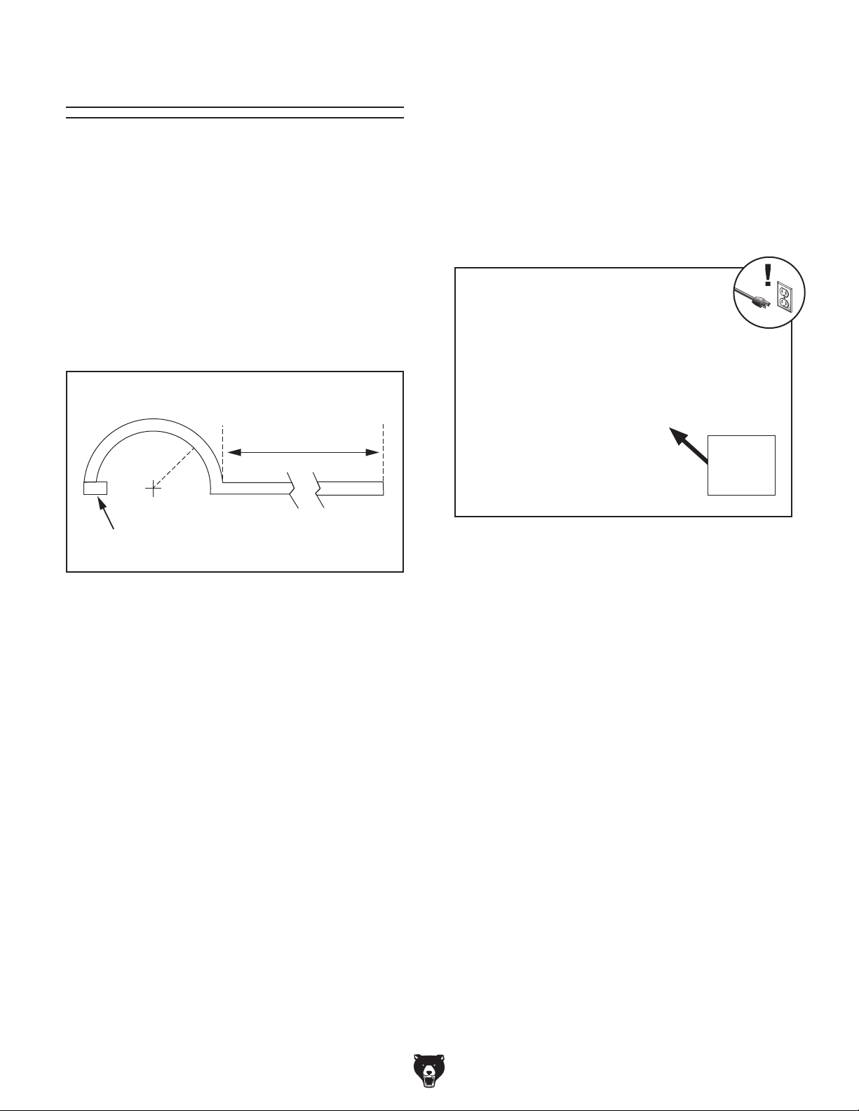
Bearing Preload
4. Remove chuck (see Page 33), then shift spin-
dle to neutral by moving FWD/REV switch to
"0" (see Figure 119 on Page 75).
This lathe is shipped from the factory with the
spindle bearing preload adjusted. If the spindle
ever develops a bit of end-play and the workpiece
finish suffers, you can adjust the bearing preload to remove the end-play and improve the
workpiece finish.
Adjusting the bearing preload requires using a
spanner wrench or a punch and hammer. You
can either purchase the spanner wrench at a tool
store or fabricate one, using the diagram shown
in Figure 120.
Fabricate from CRS
or HRS bar stock
"
16
3
/
1
12"
Radius
Fabricate pin to 7/32" D x 1/4" L and weld.
Place chuck key in cam-lock socket and keep
5.
spindle from rotating.
Using a spanner wrench, or hammer and
6.
punch, rotate outer spanner nut (see
Figure 121) counterclockwise and remove it.
Outer
Spanner
Nut
Figure 121. Loosening outer spanner nut.
Figure 120. Spanner wrench diagram.
Tools Needed Qty
3
Spanner Wrench 1
Chuck Key
......................................................... 1
Dead Blow Hammer
Piece of Scrap Wood 2"x 2" x 6"
Dial Indicator
..................................................... 1
Hex Wrench 6mm
⁄16" ....................................... 1
.......................................... 1
....................... 1
.............................................. 1
To adjust bearing preload:
Run lathe for 20 minutes at high speed to
1.
bring lathe to normal operating temperature.
DISCONNECT MACHINE FROM POWER!
2.
3. Remove end gear cover.
Loosen inner spanner nut one turn.
7.
Note: You may have to tap on the outboard
end of the spindle as explained in Step 8
on Page 77, to help unload the spindle and
break the spanner nut loose.
-76-
Model G0949G (Mfd. Since 01/22)
Page 79

8.
Place a wooden block over outboard end
of spindle, and tap it a few times with a
small sledge or heavy dead blow hammer
(see Figure 122).
Insert chuck key into a cam socket to prevent
11.
spindle from turning, then tighten inner spanner nut until dial indicator needle just stops
moving (see Figure 124).
Note: Your goal is to slide the spindle forward
just enough to introduce spindle end-play that
you can feel by hand.
Figure 122. Introducing detectable end-play.
9. Place a dial indicator on cross slide and move
carriage toward headstock until contact point
of indicator touches spindle face, as shown in
Figure 123.
Note: For convenience and accuracy, we
recommend having another person watch the
dial while you tighten the inner spanner nut.
Figure 124. Adjusting spindle bearings.
While tightening the inner spanner nut,
rock the spindle back and forth slightly with
the chuck key to make sure the spindle
tapered roller bearings seat properly in their
races.
When the dial indicator needle stops mov-
ing, there will be no spindle end-play and no
bearing preload. It is important that you find
this point without tightening the spanner nut
too much and inadvertently preloading the
spindle bearings.
Figure 123. Example of dial indicator setup.
10.
Move carriage an additional 0.100" toward
headstock.
Model G0949G (Mfd. Since 01/22)
If you think you have gone past the zero end-
play point, unload the bearings by repeating
Steps 8–9, then re-tighten the inner spanner
nut until it has reached the zero end-play
position.
-77-
Page 80
Tighten inner spanner nut an additional 1⁄16"
12.
along its circumference. See Figure 125 for
an example of this measurement.
To confirm bearings are correctly preloaded:
Re-attach all removed lathe components and
1.
prepare lathe for operation.
1
⁄16" Travel
Inner Nut
Outer Nut
Figure 125. Final spanner nut rotation.
Without allowing inner spanner nut to tighten
13.
any further, install and tighten outer spanner
nut against inner nut (see Figure 126).
IMPORTANT: DO NOT overtighten outer
spanner nut because additional preload can
force bearings even tighter against races in
the headstock and cause headstock to compress, crack, or cause bearing failure.
Install chuck and tighten jaws.
2.
3. Set spindle speed to its highest setting.
4. Connect lathe to power and turn lathe spindle
ON.
Let lathe run for 20 minutes, periodically
5.
shutting it down a few times and checking
temperature.
IMPORTANT: Stop running lathe if the tem-
perature gets too hot. If you can not comfortably touch spindle nose immediately disconnect machine from power.
Turn spindle OFF, disconnect lathe from
6.
power, and check temperature of spindle.
— If spindle nose is slightly warm to the
touch, you have correct bearing preload.
— If spindle nose is hotter than you can com-
fortably keep your hand on, preload is too
tight and you must repeat bearing preload
adjustment procedure. When repeating
the procedure, rotate the inner spanner
nut a little less during Step 12 in the preceding instructions.
Outer Nut
Figure 126. Outer spanner nut re-installed.
14.
Re-install end gear cover.
-78 -
Model G0949G (Mfd. Since 01/22)
Page 81

These pages are current at the time of printing. However, in the spirit of improvement, we may make changes to the electrical systems of future machines. Compare the manufacture date of your machine to the one
number and manufacture date of your
machine before calling. This information can be found on the main machine label.
SECTION 8: WIRING
stated in this manual, and study this section carefully.
If there are differences between your machine and what is shown in this section, call Technical Support at
(570) 546-9663 for assistance BEFORE making any changes to the wiring on your machine. An updated
wiring diagram may be available. Note: Please gather the serial
Wiring Safety Instructions
SHOCK HAZARD. Working on wiring that is con-
nected to a power source is extremely dangerous.
Touching electrified parts will result in personal
injury including but not limited to severe burns,
electrocution, or death. Disconnect the power
from the machine before servicing electrical components!
MODIFICATIONS. Modifying the wiring beyond
what is shown in the diagram may lead to unpredictable results, including serious injury or fire.
This includes the installation of unapproved aftermarket parts.
WIRE CONNECTIONS. All connections must
be tight to prevent wires from loosening during
machine operation. Double-check all wires disconnected or connected during any wiring task to
ensure tight connections.
CIRCUIT REQUIREMENTS. You MUST follow
the requirements at the beginning of this manual
when connecting your machine to a power source.
WIRE/COMPONENT DAMAGE. Damaged wires
or components increase the risk of serious personal injury, fire, or machine damage. If you notice
that any wires or components are damaged while
performing a wiring task, replace those wires or
components.
MOTOR WIRING. The motor wiring shown in
these diagrams is current at the time of printing
but may not match your machine. If you find this
to be the case, use the wiring diagram inside the
motor junction box.
CAPACITORS/INVERTERS. Some capacitors
and power inverters store an electrical charge for
up to 10 minutes after being disconnected from
the power source. To reduce the risk of being
shocked, wait at least this long before working on
capacitors.
EXPERIENCING DIFFICULTIES. If you are experiencing difficulties understanding the information
included in this section, contact our Technical
Support at (570) 546-9663.
The photos and diagrams
included in this section are
best viewed in color. You
can view these pages in
color at www.grizzly.com.
Model G0949G (Mfd. Since 01/22)
-79 -
Page 82
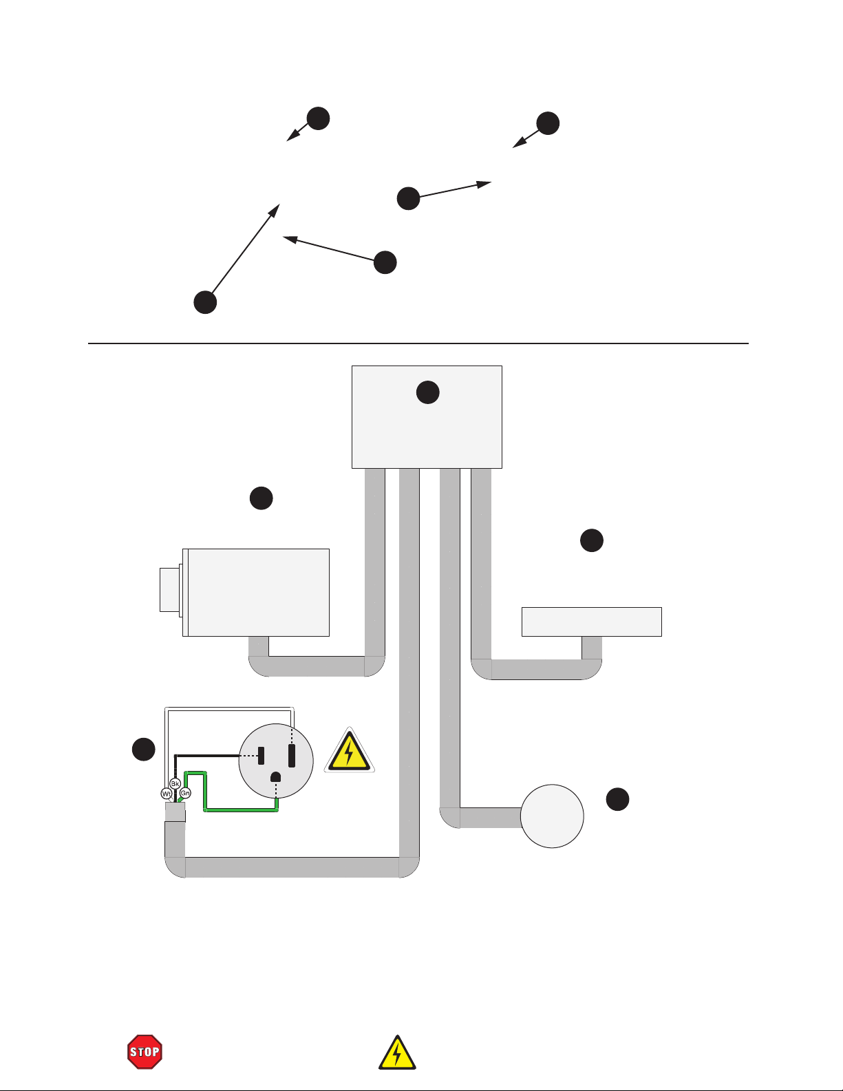
Wiring Overview
B
B
B
Motor
(Page 82)
A
E
D
C
A
Electrical
Cabinet
(Page 80)
D
Control
Panel
(Page 83)
-80-
Neutral
C
Hot
Ground
READ ELECTRICAL SAFETY
ON PAGE 79!
110 VAC
5-15 Plug
10V
E
VS Dial
(Page 84)
Model G0949G (Mfd. Since 01/22)
Page 83
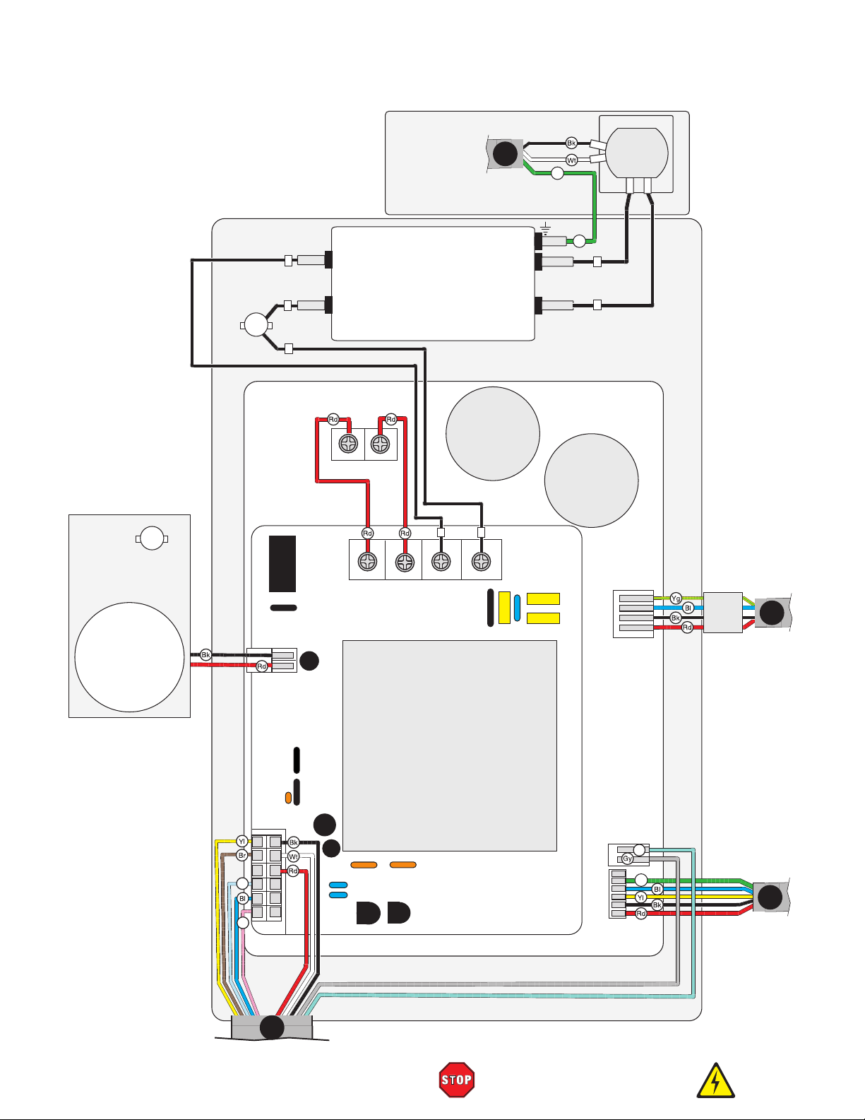
Electrical Cabinet Wiring
Fuse
20 AMP
To inside of
electronic cabinet
Cooling Fan
SOMREAL
DC: 24V
0.125
DONGGUAN SHI XIAN
YUE JI DIAN CO. LTD
Fuse
20 AMP
-
+
To Plug
(Page 79)
C
Gn
Ground
N
N
L
L
K1
D2
C10
X4
X1 (Top)
T1
EMI Filter
EMI Filter
CZ Feishuo Electronics
DL20K13/01
EMI Filter
N
JD-139B REV A 160129 X1
L
C5
R7
R1
C2
C1
Master Power
Switch
JUCHE
JCH13-20A
Gn
N
L
Circuit Board
(Bottom)
X3
EMI
Noise
Suppressor
B
To Motor
(Page 84)
(Behind Circuit Board)
D3
D1
C6
P5
Lb
Pk
To Control Panel
(Page 83)
D
Model G0949G (Mfd. Since 01/22)
AS4826-U-1500-1875-D
C8 C9
R3
MIN
MAX
R4
Transformer
ASN Electronics
JD-139A REV A 170413
Tu
Gn
Circuit Board
P4
P4
READ ELECTRICAL SAFETY
ON PAGE 79!
B
To Motor
(Page 84)
-81-
Page 84
Electrical Cabinet
EMI Filter
EMI Noise
Suppressor
Transformer
Figure 127. Electrical cabinet wiring.
-82-
Figure 128. Master power switch.
READ ELECTRICAL SAFETY
ON PAGE 79!
Model G0949G (Mfd. Since 01/22)
Page 85
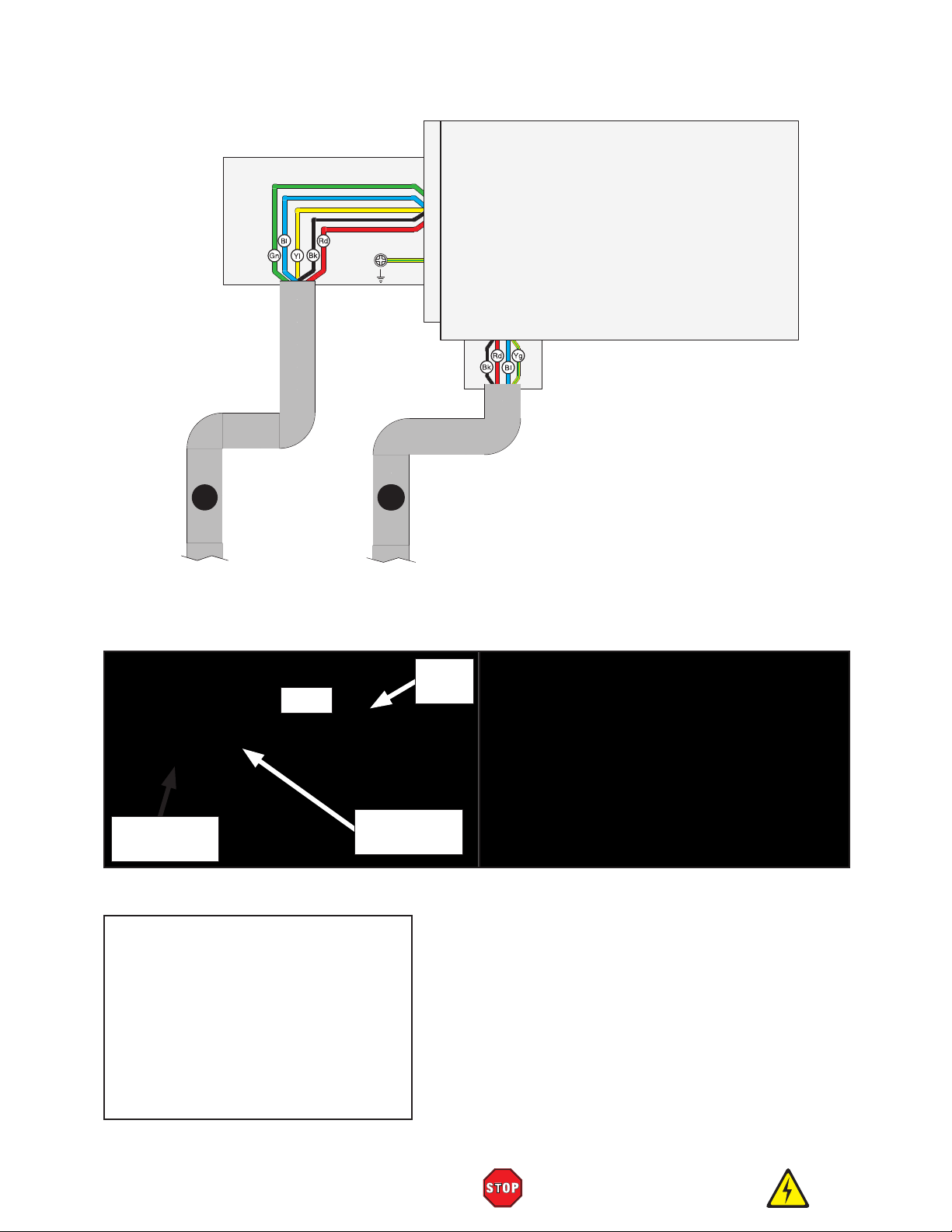
To Internal Motor
Circuit Board
Motor
Motor
Wiring
Cover
A
To Electrical
Cabinet Circuit
Board P4
Ground
A
A
To Electrical
Cabinet Circuit
Board X3
(Page 80)(Page 80)
Motor 110V
Motor 110V
To Internal Motor
Circuit Board
Motor Wiring
Cover
Power
Motor
Cord
Motor Wiring
Cover
Figure 129. Motor and motor wiring cover.
Figure 130. Motor wiring cover.
Model G0949G (Mfd. Since 01/22)
READ ELECTRICAL SAFETY
ON PAGE 79!
-83-
Page 86
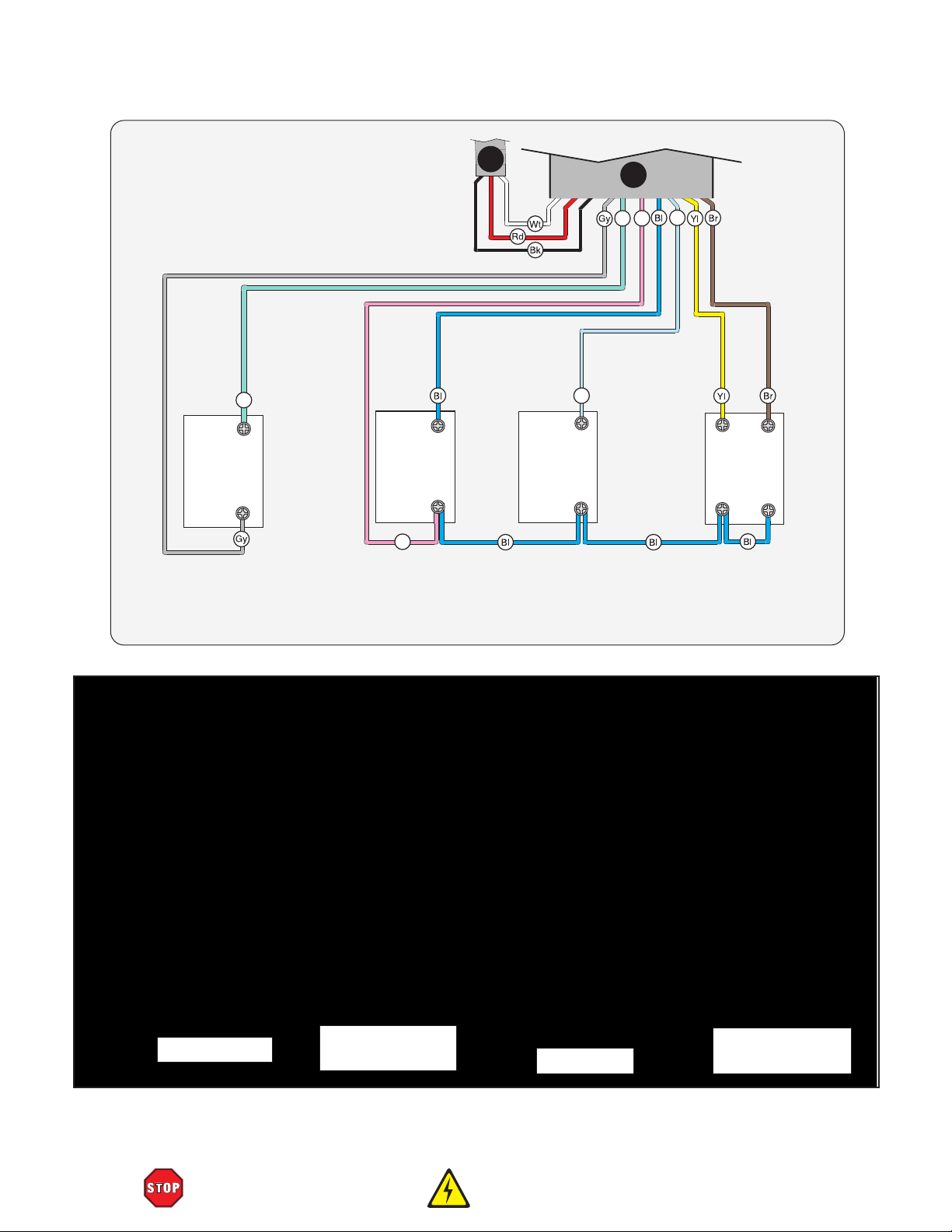
Control Panel
Tu
2
LA125H-BE102C
LA125HBE102C
NC
1
1 NC 2
E-Stop
Button Switch
(Minger)
To Variable
Speed Dial
(Page 84)
4
LA252H-BE101C
NO
3
Pk
ON Button
Switch
(YIJIA)
E
Lb
2
LA252H-BE102C
NC
1
OFF Button
Switch
(YIJIA)
A
To Electrical Box
(Circuit Board)
(Page 80)
Tu
Lb
Pk
3 NO
3
4
4
NO
LA125H-BE101C
NO
4
4 3
Spindle
Direction
Switch
(Minger)
-84-
E-Stop Switch
ON Switch
W/LED Indicator
READ ELECTRICAL SAFETY
ON PAGE 79!
OFF Switch
Figure 131. Control panel.
Spindle Direction
Switch
Model G0949G (Mfd. Since 01/22)
Page 87
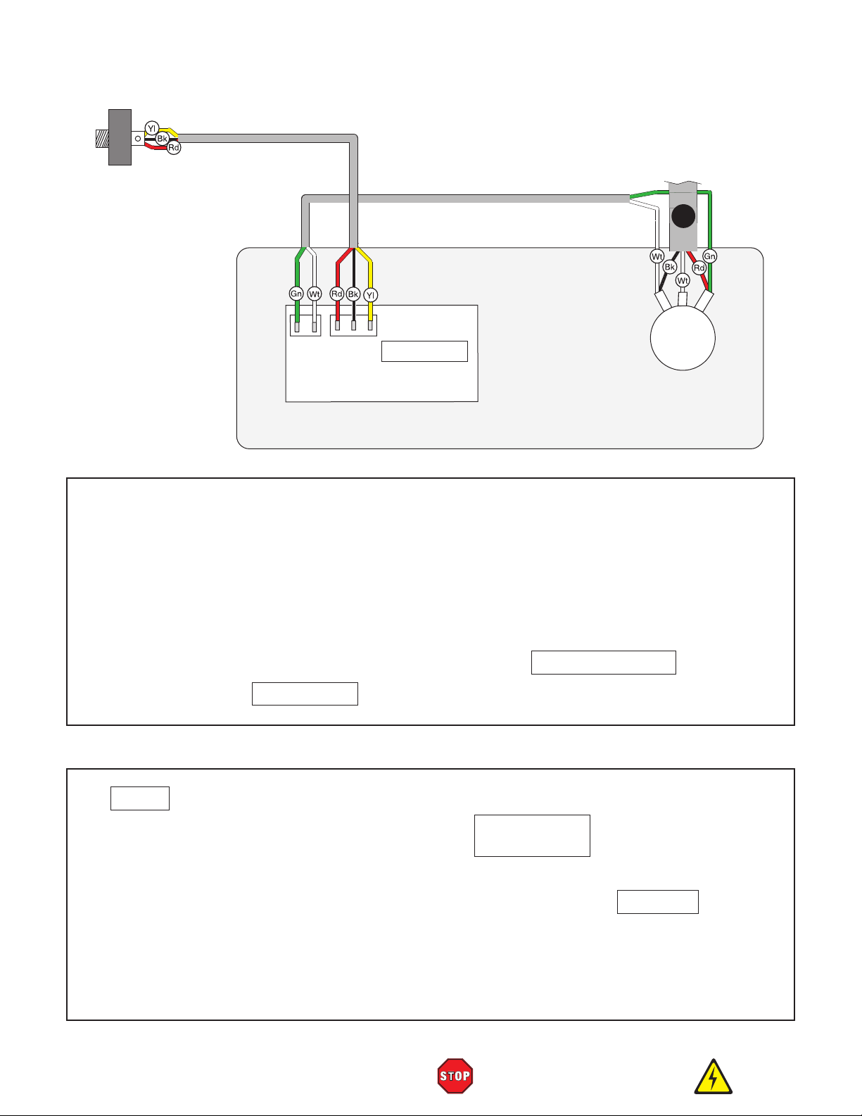
Variable Speed Dial & RPM Indicator
Spindle
Speed
Sensor
RPM
Indicator
Gnd
Gnd
5V
5V
S
SN200305
To Control
Panel
(Page 83)
A
123
B103
10V
171C
Variable Speed Dial
(Potentiometer)
R24YN20S
Spindle
Variable Speed Dial
RPM Indicator
Figure 132. Variable speed dial and RPM indicator.
Spindle
Speed Indicator
End Gears
Figure 133. Spindle speed indicator.
Model G0949G (Mfd. Since 01/22)
READ ELECTRICAL SAFETY
ON PAGE 79!
-85-
Page 88

71
SECTION 9: PARTS
Please Note: We do our best to stock replacement parts whenever possible, but we cannot guarantee that all parts shown here
are available for purchase. Call (800) 523-4777 or visit our online parts store at www.grizzly.com to check for availability.
Headstock
83
80
65
59
64
87
66
23
67
60
21
24
22
20
81
27
82
17
61
21
25
62
18
26
19
28
15
32
63
14
29
104
87
16
30
100
12
33
99
88
98
86
31
13
101
85
34
97
102
11
35
91
84
96
103
38
36
101
102
92
75
95
40
94
90
6
89
1
37
93
10
41
39
2
43
9
44
76
42
37
45
7
38
38
37
46
48
47
57
58
69
5
72
73
8
3
49
50
51
3
56
55
70
4
68
74
77
52
53
54
-86-
BUY PARTS ONLINE AT GRIZZLY.COM !
Scan QR code to visit our Parts Store.
Model G0949G (Mfd. Since 01/22)
Page 89

REF P ART # DE SCRI PTI ON REF P ART # DESCRI PTI ON
Headstock Parts List
1 P0949G0001 HEADS TOCK HOUS I NG 52 P0949G0052 SPEED RANGE SHAFT
2 P0949G0002 HEADSTOCK CONTROL PANEL PLATE 53 P0949G0053 GEAR PLATE, HIGH/LOW
3 P0949G0003 CAP SCREW M4-.7 X 8 54 P0949G0054 FLA T HD SCR M5 -. 8 X 1 2
4 P0949G0004 SPI NDLE 55 P0949G0055 GEAR HANDLE, HIGH/LOW
5 P0949G0005 KEY 8 X 32 X 56 56 P0949G0056 SET SCREW M6-1 X 10
6 P0949G0006 KEY 8 X 20 X 56 57 P0949G0057 STEEL BALL 6MM
7 P0949G0007 I NBOARD SPINDLE BEARING COVER 58 P0949G0058 COMPRESSION SPRING 1 X 5 X 30
8 P0949G0008 CAP SCREW M6-1 X 16 59 P0949G0059 MOTOR PULLEY
9 P0949G0009 I NBOARD SPINDLE BEARING COVER 60 P0949G0060 SET SCREW M6-1 X 10
10 P0949G0010 TAPERED ROLLER BEARING 32012 61 P0949G0061 MOTOR MOUNTING PLATE
11 P0949G0011 GEAR 50T 62 P0949G0062 KEY 6 X 6 X 30 RE
12 P0949G0012 GEAR 38T 63 P0949G0063 MOTOR 1-1/2HP 110V 1-PH
13 P0949G0013 EXT RETAI NI NG RI NG 5 2MM 64 P0949G0064 FLAT WASHER 8MM
14 P0949G0014 TAPERED ROLLER BEARING 32012 65 P0949G0065 CAP SCREW M8-1.25 X 25
15 P0949G0015 OUTBOARD SPINDLE GASKET 66 P0949G0066 CAP SCREW M8-1.25 X 25
16 P0949G0016 OUTBOARD SPINDLE COVER 67 P0949G0067 FL AT WA SHE R 8MM
17 P0949G0017 CAP SCREW M6-1 X 16 68 P0949G0068 CAML OCK
18 P0949G0018 BEAD COLLAR 69 P0949G0069 PI N
19 P0949G0019 BEAD 70 P0949G0070 COMPRESSION SPRING 1 X 5 X 30
20 P0949G0020 GEAR 40T 71 P0949G0071 HEX BOLT M8-1.25 X 16
21 P0949G0021 SPANNER NUT M48-5 X 1.5 72 P0949G0072 HEX NUT M8-1
22 P0949G0022 SPANNER NUT M20-2.5 X 1. 5 73 P0949G0073 BRASS TIP
23 P0949G0023 V-BELT PULLEY 74 P0949G0074 HEX BOLT M8-1 X 25
24 P0949G0024 V-BELT V10 X 630 75 P0949G0075 OIL DRAIN PLUG 3/8"
25 P0949G0025 BUSHI NG 76 P0949G0076 OIL SIGHT GLASS M18 X 1.5
26 P0949G0026 GEAR SHAFT END COVER 77 P0949G0077 VARIABLE SPEED CONTROL PANEL
27 P0949G0027 CAP SCREW M6-1 X 16 80 P0949G0080 END GEAR COVER
28 P0949G0028 OIL SEAL 81 P0949G0081 SLI DI NG DOOR FRAME
29 P0949G0029 GASKET 82 P0949G0082 SLIDING DOOR
30 P0949G0030 BALL BEARING 6004ZZ 83 P0949G0083 CAP SCREW M4-.7 X 8
31 P0949G0031 GEAR SHAFT 84 P0949G0084 FLAT WASHER 8MM
32 P0949G0032 KEY 6 X 6 X 20 85 P0949G0085 STUD-DE M8-1.25 X 137, 11LH, 11
33 P0949G0033 KEY 5 X 5 X 56 86 P0949G0086 FLAT WASHER 8MM
34 P0949G0034 GEAR 28T 87 P0949G0087 KNOB M8-1.25, 7-LOBE, D32
35 P0949G0035 GEAR 19T 88 P0949G0088 ELECTRICAL BOX
36 P0949G0036 BUSHI NG 89 P0949G0089 GASKET
37 P0949G0037 BALL BEARING 6003ZZ 90 P0949G0090 GEARBOX COVER
38 P0949G0038 PLUG 91 P0949G0091 CAP SCREW M6-1 X 16
39 P0949G0039 GEAR SHAFT 92 P0949G0092 OIL PLUG M18 X 1.5
40 P0949G0040 KEY 5 X 5 X 70 RE 93 P0949G0093 SPEED SENSOR RING W/MAGNETS
41 P0949G0041 GEAR 27T 94 P0949G0094 PROBE HOLDER
42 P0949G0042 KEY 6 X 6 X 32 RE 95 P0949G0095 CAP SCREW M4-.7 X 16
43 P0949G0043 GEAR 36T 96 P0949G0096 TENSION WHEEL ARM
44 P0949G0044 GEAR 24T 97 P0949G0097 FLAT WASHER 10MM
45 P0949G0045 SET SCREW M6-1 X 10 98 P0949G0098 LOCK WASHER 10MM
46 P0949G0046 SHIFTING FORK 99 P0949G0099 CAP SCREW M10-1.5 X 25
47 P0949G0047 ROCKER ARM 100 P0949G0100 TENSION WHEEL SHAFT
48 P0949G0048 SET SCREW M6-1 X 10 101 P0949G0101 BALL BEARING 6001ZZ
49 P0949G0049 HEX NUT M5-. 8 102 P0949G0102 I NT RETAI NI NG RING 28MM
50 P0949G0050 SET SCREW M5-.8 X 12 103 P0949G0103 TENSI ON WHEEL
51 P0949G0051 O-RING 11.2 X 2.65 104 P0949G0104 EXT RETAI NI NG RI NG 1 2MM
Model G0949G (Mfd. Since 01/22)
BUY PARTS ONLINE AT GRIZZLY.COM !
Scan QR code to visit our Parts Store.
-87-
Page 90

267
Gearbox
271
250
250
249
214
221
245
249
247
217
244
247
217
218
251
266
246
216
220
248
248
219
243
211
253
215
224
241
213
218
237
252
254
250
212
242
268
254
258
210
255
217
240
238
249
209
239
269
256
247
222
230
223
231
257
248
265
229
273
228
264
227
263
224
236
212
272
208
275
235
233
226
207
276
206
202
234
214
203
280
281
204
205
201
276
277
279
278
232
231
274
225
-88-
270
BUY PARTS ONLINE AT GRIZZLY.COM !
Scan QR code to visit our Parts Store.
262
261
260
259
Model G0949G (Mfd. Since 01/22)
Page 91

Gearbox Parts List
REF PART # DES CRIP TION REF PART # DES CRIP TION
201 P0949G0201 FEED ROD SH AFT 242 P0949G0242 GEAR 24T
202 P0949G0202 KEY 4 X 4 X 12 RE 243 P0949G0243 EXT RETAINING RING 16MM
203 P0949G0203 BEARIN G SH EATH 244 P0949G0244 BU SH IN G 16ID X 18OD X 10L
204 P0949G0204 THRUST BEARING 51103 245 P0949G0245 LEFT PLU G
205 P0949G0205 BALL BEAR IN G 6202Z Z 246 P0949G0246 SHIFT ING FORK
206 P0949G0206 SLOTTED W ASHER 18 X 20 X 3 247 P0949G0247 ROCKER ARM
207 P0949G0207 FLAN GED BU SH IN G 24 X 18 X 17 248 P0949G0248 ROLL PIN 3 X 20
208 P0949G0208 GEAR 24T 249 P0949G0249 FEED SELECT ION SHAF T
209 P0949G0209 BUSHING 250 P0949G0250 O- RING 6.7 X 1.8
210 P0949G0210 GEAR SH AFT 24T 251 P0949G0251 SHIFTING FORK
211 P0949G0211 KEY 5 X 5 X 12 RE 252 P0949G0252 COMBO GEAR 16T /32T /24T
212 P0949G0212 BALL BEAR IN G 6202Z Z 253 P0949G0253 COLLAR
213 P0949G0213 LEFT FLANGE 254 P0949G0254 BU SH IN G 10ID X 12OD X 10L
214 P0949G0214 CAP SC REW M5- .8 X 12 255 P0949G0255 GEAR 24T
215 P0949G0215 EXT RETAINING RING 14MM 256 P0949G0256 RIGHT PLUG
216 P0949G0216 COLLAR 257 P0949G0257 SHAF T
217 P0949G0217 O- RING 18 X 2.4 P18 258 P0949G0258 GEARBOX COVER ( FR ON T)
218 P0949G0218 EXT RETAINING RING 18MM 259 P0949G0259 FEED SELECTION KN OB
219 P0949G0219 BUSHING 18ID X 20OD X 15L 260 P0949G0260 SET SC REW M 6-1 X 10
220 P0949G0220 GEAR 24T 261 P0949G0261 COM PRESSION SPR IN G 0.7 X 4.7 X 16
221 P0949G0221 SHAF T 262 P0949G0262 STEEL BALL 5MM
222 P0949G0222 GEARBOX 263 P0949G0263 FLAT W ASHER 12M M
223 P0949G0223 CAP SC REW M6- 1 X 50 264 P0949G0264 H EX N UT M 12-1.75
224 P0949G0224 OIL PLU G 3/8" 265 P0949G0265 HEX NUT M 12- 1.75
225 P0949G0225 COLLAR 266 P0949G0266 EXT RETAINING RING 25MM
226 P0949G0226 RIGHT FLANGE 267 P0949G0267 C AP SCREW M6-1 X 12
227 P0949G0227 SHAF T 268 P0949G0268 SET SC REW M5- .8 X 5
228 P0949G0228 BUSHING 8ID X 10D X 12L 269 P0949G0269 STEEL BALL 6.5M M
229 P0949G0229 FLANGED BUSHING 8ID X 10D X 7.5L 270 P0949G0270 OIL SIGHT GLASS M18 X 1.5
230 P0949G0230 GEAR 24T 271 P0949G0271 CAP SC REW M5- .8 X 20
231 P0949G0231 EXT RETAINING RING 15MM 272 P0949G0272 GEAR BOX COVER ( R EAR)
232 P0949G0232 GEAR 24T 273 P0949G0273 BUTTON HD CAP SCR M5-.8 X 8
233 P0949G0233 GEAR SH AFT 16T 274 P0949G0274 ROLL PIN 5 X 20
234 P0949G0234 KEY 4 X 4 X 25 RE 275 P0949G0275 OVERLOAD SHAFT SLEEVE
235 P0949G0235 KEY 4 X 4 X 8 RE 276 P0949G0276 SET SC REW M6- 1 X 10
236 P0949G0236 GEAR 32T 277 P0949G0277 STEEL BALL 6MM
237 P0949G0237 SET SC REW M 6-1 X 10 278 P0949G0278 COMPR ESSION SPRING 0.7 X 4.7 X 16
238 P0949G0238 SHAF T 279 P0949G0279 SET SC REW M8- 1.25 X 8
239 P0949G0239 KEY 4 X 4 X 45 280 P0949G0280 GEARBOX OIL PLUG C OVER
240 P0949G0240 KEY 4 X 4 X 20 281 P0949G0281 CAP SC REW M5- .8 X 30
241 P0949G0241 BUSHING 16ID X 18OD X 15L
Model G0949G (Mfd. Since 01/22)
BUY PARTS ONLINE AT GRIZZLY.COM !
Scan QR code to visit our Parts Store.
-89-
Page 92

Carriage
378
329
305
322
327
328
304
301
326
325
302
305
377
303
321
324
376
320
319
332
333
306
323
393
307
334
388
306
309
335
392
390
310
331
391
389
386
308
387
313
380
385
311
312
315
314
343
382
381
317
383
384
388
387
386
385
379
318
316
331
342
354
353
352
356
330
355
351
341
347
350
338
340
348
347
344
339
357
349
374
336
346
337
358
375
345
362
361
359
371
372
360
370
365
366
373
333
368
369
370
364
363
367
-90-
BUY PARTS ONLINE AT GRIZZLY.COM !
Scan QR code to visit our Parts Store.
Model G0949G (Mfd. Since 01/22)
Page 93

Carriage Parts List
REF P ART # DE SCRIP TIO N REF P ART # DESCRIPTIO N
301 P0949G0301 COMPOUND S LIDE 348 P0949G0348 BACKING PLATE
302 P0949G0302 PLUNGER 349 P0949G0349 CAP SCREW M5-.8 X 20
303 P0949G0303 COMPRESSION SPRING 0.7 X 7 X 13 350 P0949G0350 G RADUATED DIAL
304 P0949G0304 COMPOUND SLIDE GIB 351 P0949G0351 SPRING PLATE
305 P0949G0305 GIB SCREW M5-.8 X 30 352 P0949G0352 HA NDLEWHEEL HUB
306 P0949G0306 THRUST BEARING 51101 353 P0949G0353 HUB COVER
307 P0949G0307 LEADSCREW BRACKET 354 P0949G0354 SET SCREW M4-.7 X 6
308 P0949G0308 CAP SCREW M6-1 X 25 355 P0949G0355 HOLLOW HANDLE 22 X 65, 10
309 P0949G0309 GRADUATE D DI AL 356 P0949G0356 SHOULDER SCR M8-1.25 X, 10 X 75
310 P0949G0310 HANDWHEEL HUB 357 P0949G0357 SADDLE
311 P0949G0311 COMP SPRING .5 X 3.5 X 12 358 P0949G0358 GIB SLIDE (LEFT)
312 P0949G0312 STEEL BALL 4MM 359 P0949G0359 CAP SCREW M8-1.25 X 30
313 P0949G0313 HUB COVER 360 P0949G0360 GIB SLIDE (RIGHT)
314 P0949G0314 SET SCREW M5-.8 X 6 361 P0949G0361 ROLL PIN 5 X 16
315 P0949G0315 HOLLOW HANDLE 12 X 40, 6 362 P0949G0362 GIB SUPPORT SCR M8-1.25 X 40
316 P0949G0316 SHOULDER SCREW M7-1.0 X 15, 5 X 50 363 P0949G0363 BACK CLAMP PLATE
317 P0949G0317 HOLLOW HANDLE 12 X 25, 6 364 P0949G0364 GIB STRIP
318 P0949G0318 SHOULDER SCREW M7-1.0 X 10, 5 X 30 365 P0949G0365 HEX NUT M6-1
319 P0949G0319 LEADSCREW 366 P0949G0366 SET SCREW M6-1 X 16
320 P0949G0320 KEY 4 X 4 X 10 RE 367 P0949G0367 CAP SCREW M8-1.25 X 30
321 P0949G0321 LEADS CREW NUT 368 P0949G0368 STRAIGHT WAY WIPER
322 P0949G0322 SWIVEL SLIDE 369 P0949G0369 STRA I GHT WIPE R CLAMP
323 P0949G0323 SET SCREW M6-1.0 X 8 370 P0949G0370 BUTTTON HD CAP SCREW M4-. 7 X 10
324 P0949G0324 PIVOT PIN 371 P0949G0371 NOTCHE D WAY WI PER
325 P0949G0325 HEX NUT M8- 1.25 372 P0949G0372 NOTCHED WI PER CLAMP
326 P0949G0326 FLAT WAS HER 8MM 373 P0949G0373 CAP SCREW M5-.8 X 10
327 P0949G0327 T-BOLT M8-1.25 X 20 374 P0949G0374 TAPER PIN 3 X 35
328 P0949G0328 CROSS SLIDE 375 P0949G0375 CAP SCREW M8-1.25 X 30
329 P0949G0329 GRADUATED SCALE 376 P0949G0376 TOOL POST BASE
330 P0949G0330 GIB 377 P0949G0377 SET SCREW M6-1 X 8
331 P0949G0331 GIB SCREW M5-.8 X 30 378 P0949G0378 TOOL POST SHAFT
332 P0949G0332 CAP SCREW M8-1.25 X 20 379 P0949G0379 KNIFE SEAT
333 P0949G0333 BALL OILER 6MM PRESS-IN 380 P0949G0380 TOOL POST HANDLE HUB
334 P0949G0334 ROLL PIN 5 X 15 381 P0949G0381 BUSHING
335 P0949G0335 CAP SCREW M6-1 X 20 382 P0949G0382 FLANG E NUT M16-2
336 P0949G0336 LEADS CREW NUT 383 P0949G0383 STUD-DE M10-1.5 X 96, 10RH
337 P0949G0337 SET SCREW M4-.7 X 8 384 P0949G0384 KNOB M10-1.5, D32, ROUND
338 P0949G0338 GEAR 20T 385 P0949G0385 SMALL SHAFT
339 P0949G0339 SET SCREW M5-.8 X 5 386 P0949G0386 COMP SPRING 1.2 X 19 X 18
340 P0949G0340 LEADSCREW 387 P0949G0387 BLOCK
341 P0949G0341 KEY 4 X 4 X 10 RE 388 P0949G0388 CAP SCREW M5-.8 X 10
342 P0949G0342 KEY 4 X 4 X 10 RE 389 P0949G0389 K NI FE CLI P
343 P0949G0343 CHIP G UARD 390 P0949G0390 STUD-FT M8-1.25 X 12 LH
344 P0949G0344 SUPPO RT HUB 391 P0949G0391 KNURLE D THUMB NUT M10-1. 5
345 P0949G0345 FLAT WAS HER 8MM 392 P0949G0392 HEX NUT M10-1
346 P0949G0346 CAP SCREW M8-1.25 X 20 393 P0949G0393 SET SCREW M10-1.5 X 20 DOG-PT
347 P0949G0347 THRUST BEARING 51101
Model G0949G (Mfd. Since 01/22)
BUY PARTS ONLINE AT GRIZZLY.COM !
Scan QR code to visit our Parts Store.
-91-
Page 94

Apron
406
401
402
403
475
474
404
405
476
475
408
407
409
448
442
410
412
413
433
414
415
411
432
405
416
417
422
418
423
405
419
421
405
438
420
424
437
405
425
436
426
430
429
428
427
431
435
434
462
461
459
442
441
460
474
470
435
463
464
465
473
467
466
458
469
456
455
468
472
443
471
454
441
442
457
451
453
452
449
450
441
442
443
446
439
440
445
447
444
-92-
BUY PARTS ONLINE AT GRIZZLY.COM !
Scan QR code to visit our Parts Store.
Model G0949G (Mfd. Since 01/22)
Page 95

Apron Parts List
REF PART # DESCRI PTION REF PART # DESCRI PTION
401 P0949G0401 GEAR 40T 439 P0949G0439 SET SCREW M6-1 X 20 DOG-PT
402 P0949G0402 ROLL PIN 5 X 20 440 P0949G0440 SET SCREW M6-1 X 8
403 P0949G0403 GEAR 66T 441 P0949G0441 STEEL BALL 5MM
404 P0949G0404 COLLAR 442 P0949G0442 COMPRESSION SPRING 0.7 X 4 X 10
405 P0949G0405 SET SCREW M4-.7 X 8 443 P0949G0443 SET SCREW M6-1 X 6
406 P0949G0406 PI NION GEAR SHAFT 17T 444 P0949G0444 KNOB M8-1.25, D40, TAPERED
407 P0949G0407 KEY 5 X 5 X 10 RE 445 P0949G0445 STUD-DE M8-1.25 X 12
408 P0949G0408 S HAFT 446 P0949G0446 LEVER HUB
409 P0949G0409 GEAR 26T 447 P0949G0447 ROLL PIN 5 X 45
410 P0949G0410 E XT RETAINI NG RING 8MM 448 P0949G0448 SHAFT
411 P0949G0411 ROLL PIN 5 X 25 449 P0949G0449 BASE
412 P0949G0412 GEAR 45T 450 P0949G0450 CAP SCREW M5-.8 X 10
413 P0949G0413 GEAR 36T 451 P0949G0451 HANDLE SHAFT M8 X 90
414 P0949G0414 ROLL PIN 4 X 16 452 P0949G0452 CAM SHAFT
415 P0949G0415 GEAR 36T 453 P0949G0453 ROLL PIN 5 X 20
416 P0949G0416 COLLAR 454 P0949G0454 CA M SHAFT BRACKET
417 P0949G0417 GEAR 40T 455 P0949G0455 SET SCREW M6-1 X 6
418 P0949G0418 GEAR 20T 456 P0949G0456 SET SCREW M6-1 X 10 DOG-PT
419 P0949G0419 E XT RETAINI NG RING 15MM 457 P0949G0457 KNOB M8-1.25 25D, ROUND
420 P0949G0420 S HAFT 458 P0949G0458 CAP SCREW M5-.8 X 30
421 P0949G0421 WO RM SHAFT 459 P0949G0460 SHOULDER SCR M8-1.25 X, 10 X 75
422 P0949G0422 KEY 4 X 4 X 14 460 P0949G0459 HOLLOW HANDLE 22 X 65, 10
423 P0949G0423 GEAR 34T 461 P0949G0461 FLAT WAS HER 8MM
424 P0949G0424 COLLAR 462 P0949G0462 HE X NUT M8-1. 2 5
425 P0949G0425 WORM GEAR 17T 463 P0949G0463 HANDWHEEL TYPE-8 48D X 12B X 8
426 P0949G0426 COLLAR 464 P0949G0464 B USHING
427 P0949G0427 WORM BASE 465 P0949G0465 G RADUATED DIAL
428 P0949G0428 ROLL PIN 4 X 20 466 P0949G0466 SUPPORT HUB
429 P0949G0429 CAP SCREW M4-.7 X 25 467 P0949G0467 GEAR SHAFT
430 P0949G0430 WORM GEAR 468 P0949G0468 KEY 5 X 5 X 14 RE
431 P0949G0431 BUSHING 25ID X 28OD X 10L 469 P0949G0469 KEY 3 X 3 X 10 RE
432 P0949G0432 SHOULDER SCREW M4-.7 X 16 470 P0949G0470 BALL OI LER 6MM PRESS-IN
433 P0949G0433 BRACKET 471 P0949G0471 PLATE
434 P0949G0434 PLATE 472 P0949G0472 RIVET 2.5 X 3MM BLIND
435 P0949G0435 CAP SCREW M5-.8 X 12 473 P0949G0473 OI L SIGHT GLASS M18-2.5 X 1.5
436 P0949G0436 HA LF NUT 474 P0949G0474 COLLAR
437 P0949G0437 ROLL PIN 6 X 16 475 P0949G0475 OIL PLUG 3/8"
438 P0949G0438 CA M SHAFT 476 P0949G0476 APRON CASTI NG
Model G0949G (Mfd. Since 01/22)
BUY PARTS ONLINE AT GRIZZLY.COM !
Scan QR code to visit our Parts Store.
-93-
Page 96

Steady & Follow Rests
502
503
504
505
506
507
508
509
510
513
514
515
516
512
517
518
519
520
511
501
REF PART # DES CRIP TION REF PART # DES CRIP TION
501
P0949G0501 STEADY REST ASSEMBLY
502 P0949G0502 STEADY REST CASTING 512 P0949G0512 FOLLOW REST ASSEMBLY
503 P0949G0503 FING ER 513 P0949G0513 FOLLOW REST CASTING
504 P0949G0504 SHOULDER SCREW M8-1.25 X 1 514 P0949G0514 FING ER
505 P0949G0505 LOCK WASHER 6MM 515 P0949G0515 SHOULDER SCREW M8-1.25 X 1
506 P0949G0506 HEX NUT M6 -1 516 P0949G0516 ADJ USTING SCREW
507 P0949G0507 ADJ USTING SCREW 517 P0949G0517 HEX NUT M6-1
508 P0949G0508 CLAMPING PLATE 518 P0949G0518 LOCK WASHER 6MM
509 P0949G0509 HEX BOLT M12-1.75 X 65 519 P0949G0519 CAP SCREW M8-1.25 X 35
510 P0949G0510 FLAT WASHER 10MM 520 P0949G0520 FLAT WASHE R 8MM
511 P0949G0511 HEX NUT M1 0-1.5
-94-
BUY PARTS ONLINE AT GRIZZLY.COM !
Scan QR code to visit our Parts Store.
Model G0949G (Mfd. Since 01/22)
Page 97

601
609
Tailstock
602
605
612
613
614
626
603
604
606
629
607
608
610
625
632
611
624
630
615
616
617
618
619
620
621
631
622
623
627
628
633
634
Model G0949G (Mfd. Since 01/22)
BUY PARTS ONLINE AT GRIZZLY.COM !
Scan QR code to visit our Parts Store.
-95-
Page 98
REF PART # DES CRIP TION REF P ART # DESCRIP TION
Tailstock Parts List
601 P0949G0601 TAILSTOCK QUILL M T#3 618 P0949G0618 SPRIN G PLATE
602 P0949G0602 KEY 2.5 X 6 X 12 619 P0949G0619 HAND WHL T- 8 125D X 14B X M 8- 1.25
603 P0949G0603 FLANGED BUSHING 620 P0949G0620 FLAT WASHER 10MM
604 P0949G0604 CAP SC REW M4- .7 X 12 621 P0949G0621 H EX N UT M 10-1.5
605 P0949G0605 LEADSC REW 622 P0949G0622 H OLLOW HAND LE 18 X 63, 6
606 P0949G0606 KEY 3 X 3 X 10 RE 623 P0949G0623 SH OU LD ER SCR M8- 1.25 X 10, 6 X 63
607 P0949G0607 QULL LOCK SH AFT 624 P0949G0624 SET SC REW M 6-1 X 16 DOG- PT
608 P0949G0608 FLAT WASHER 10MM 625 P0949G0625 AD JUSTMEN T BLOCK
609 P0949G0609 ADJUST ABLE HAN DLE M10- 1.5 X 50 626 P0949G0626 BASE
610 P0949G0610 BALL OILER 6M M PRESS- IN 627 P0949G0627 C AP SC R EW M 8- 1.25 X 40
611 P0949G0611 TAILSTOCK BODY 628 P0949G0628 C AP SC R EW M 8- 1.25 X 45
612 P0949G0612 COLLAR 629 P0949G0629 LOC K SC R EW M 12- 1.25 X 47
613 P0949G0613 SET SC REW M 6-1 X 10 630 P0949G0630 LOCK SHAF T
614 P0949G0614 SET SC REW M 6-1 X 10 DOG- PT 631 P0949G0631 HANDLE
615 P0949G0615 FLANGE COVER 632 P0949G0632 ROLL PIN 4 X 24
616 P0949G0616 CAP SC REW M5- .8 X 12 633 P0949G0633 C LAMPING PLATE
617 P0949G0617 GRADUATED DIAL 634 P0949G0634 H EX N UT M 12-1.75
-96-
BUY PARTS ONLINE AT GRIZZLY.COM !
Scan QR code to visit our Parts Store.
Model G0949G (Mfd. Since 01/22)
Page 99
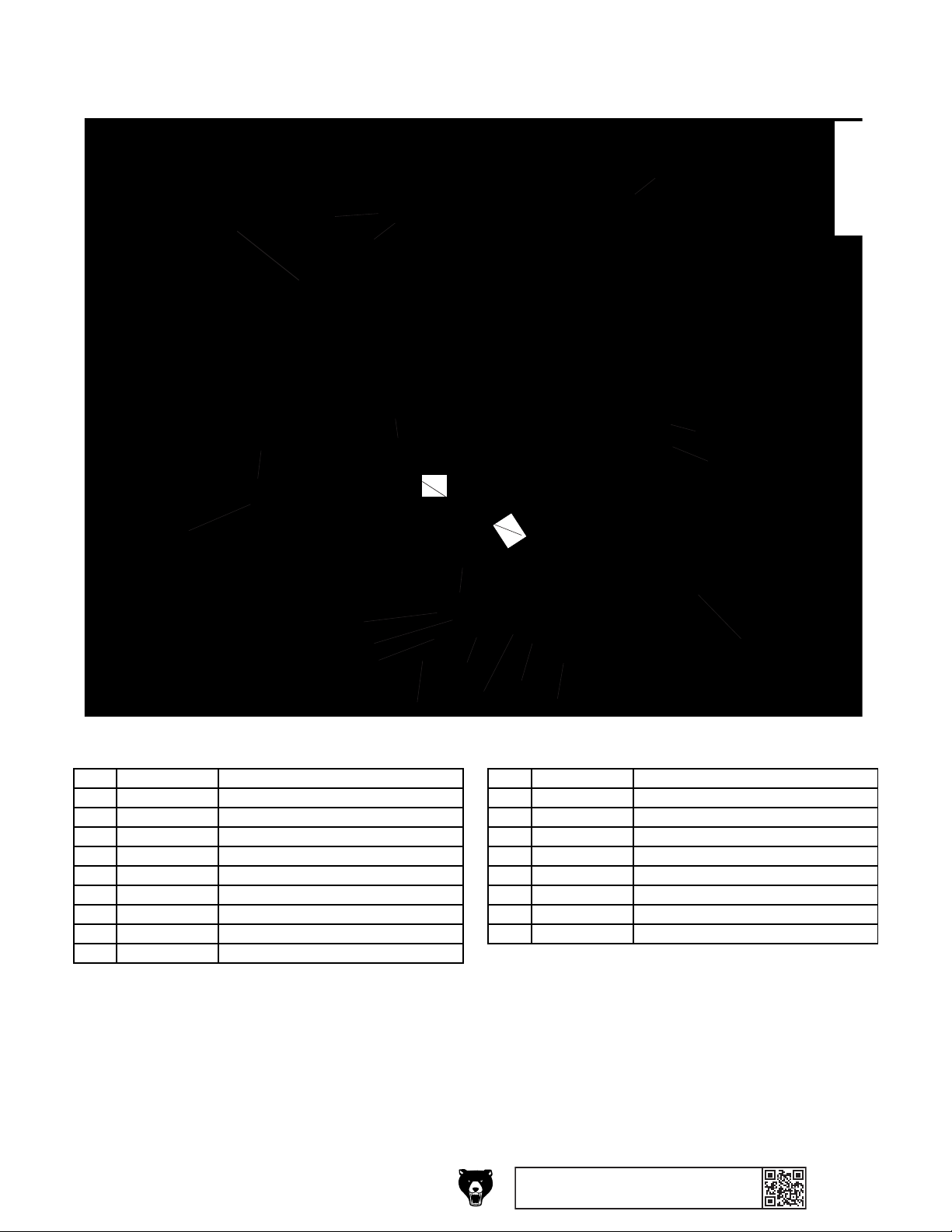
Bed
710
711
714
706
701
705
715
713
708
716
712
702
703
708
707
708
718
717
704
719
709
REF PART # DES CRIP TION REF PART # DES CRIP TION
701 P0949G0701 LATHE BED 711 P0949G0711 CAP SCREW M6-1 X 45
702 P0949G0702 RACK 712 P0949G0712 BALL OILER 6MM PRESS-IN
703 P0949G0703 CAP SCREW M6-1 X 16 713 P0949G0713 BEARING SHEATH
704 P0949G0704 ROLL PIN 5 X 20 714 P0949G0714 SPLASH GUARD
705 P0949G0705 LONGITUDINAL LEADSCREW 715 P0949G0715 FLAT WASHER 6MM
706 P0949G0706 FEED RO D 716 P0949G0716 CAP SCREW M6-1 X 16
707 P0949G0707 BRACK ET HOUSING 717 P0949G0717 HEX NUT M8- 1.25
708 P0949G0708 THRUST BEARING 51102 718 P0949G0718 CAP SCREW M8-1.25 X 30
709 P0949G0709 FLAT WASHER 12MM 719 P0949G0719 CHIP PAN
710 P0949G0710 ROUND NUT M12 -1. 25
Model G0949G (Mfd. Since 01/22)
BUY PARTS ONLINE AT GRIZZLY.COM !
Scan QR code to visit our Parts Store.
-97-
Page 100
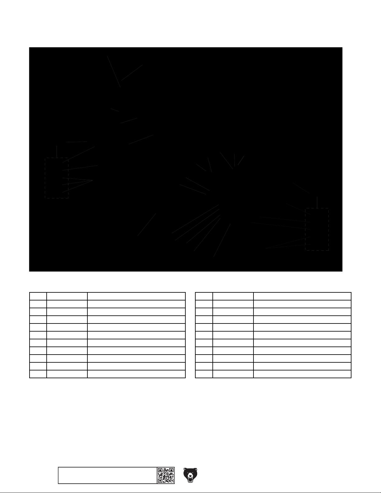
801A
REF PART # DES CRIP TION REF PART # DES CRIP TION
801
802
803
804
805
815
815
811
816
814
Cabinet
812
817
819
817
817
819
819
820
811
813
818
819
820
806A
806
807
808
809
810
801A P0949G0801A LEFT STAND ASSEMBLY 810 P0949G0810 CURVED PIN 3 X 65
801 P0949G0801 LEFT S TAND 811 P0949G0811 FRONT PLATE
802 P0949G0802 DRAWER 812 P0949G0812 BRACKET (LEFT)
803 P0949G0803 LEFT HA ND DRAWER PULL 813 P0949G0813 BRACK ET (RI G HT)
804 P0949G0804 RIG HT HAND DRAWER PULL 814 P0949G0814 HEX BOLT M10-1.5 X 40
805 P0949G0805 PHLP HD SCR 3 X .5 X 5MM 815 P0949G0815 FLAT WASHER 10MM
806A P0949G0806A RIGHT STAND ASSEMBLY 816 P0949G0816 HE X NUT M10-1 . 5
806 P0949G0806 RIG HT STAND 817 P0949G0817 CAP SCREW M6-1 X 14
807 P0949G0807 DOOR 818 P0949G0818 LOCK WASHER 6MM
808 P0949G0808 LATCH 819 P0949G0819 FLAT WA SHER 6MM
809 P0949G0809 COMPRESSION SPRING 0.7 X 3 X 45 820 P0949G0820 HEX NUT M6-1
-98-
BUY PARTS ONLINE AT GRIZZLY.COM !
Scan QR code to visit our Parts Store.
Model G0949G (Mfd. Since 01/22)
 Loading...