


MODEL G0942/G0943
EXTREME-SERIES AIR
COMPRESSORS
OWNER'S MANUAL
(For models manufactured since 03/21)
COPYRIGHT © DECEMBER, 2022 BY GRIZZLY INDUSTRIAL, INC.
WARNING : NO PORTION OF THIS MANUAL MAY BE REPRODUCED IN ANY SHAPE
OR FORM WITHOUT THE WRITTEN APPROVAL OF GRIZZLY INDUSTRIAL, INC.
#CS22467 PRINTED IN USA
***Keep for Future Reference***
V1.12 . 2 2

This manual provides critical safety instructions on the proper setup,
operation, maintenance, and service of this machine/tool. Save this
document, refer to it often, and use it to instruct other operators.
Failure to read, understand and follow the instructions in this manual
may result in fire or serious personal injury—including amputation,
electrocution, or death.
The owner of this machine/tool is solely responsible for its safe use.
This responsibility includes but is not limited to proper installation in
a safe environment, personnel training and usage authorization,
proper inspection and maintenance, manual availability and comprehension, application of safety devices, cutting/sanding/grinding tool
integrity, and the usage of personal protective equipment.
The manufacturer will not be held liable for injury or property damage
from negligence, improper training, machine modifications or misuse.
Some dust created by power sanding, sawing, grinding, drilling, and
other construction activities contains chemicals known to the State
of California to cause cancer, birth defects or other reproductive
harm. Some examples of these chemicals are:
• Lead from lead-based paints.
• Crystalline silica from bricks, cement and other masonry products.
• Arsenic and chromium from chemically-treated lumber.
Your risk from these exposures varies, depending on how often you
do this type of work. To reduce your exposure to these chemicals:
Work in a well ventilated area, and work with approved safety equipment, such as those dust masks that are specially designed to filter
out microscopic particles.

Table of Contents
INTRODUCTION ............................................... 2
Contact Info.................................................... 2
Manual Accuracy
Identification
Controls & Components
Model G0942 Machine Data Sheet
Model G0943 Machine Data Sheet
SECTION 1: SAFETY
Safety Instructions for Machinery
Additional Safety for Air Compressors
SECTION 2: POWER SUPPLY
SECTION 3: SETUP
Unpacking
Needed for Setup
Inventory
Site Considerations
Lifting & Placing
Anchoring to Floor
Power Connection........................................ 19
Test Run
SECTION 4: OPERATIONS
Operation Overview
Distribution System Design
Distribution System Components
Choosing Air Hoses
Connecting Air Tools
.................................................... 16
...................................................... 16
...................................................... 21
........................................... 2
................................................... 3
................................. 4
............... 6
............... 8
..................................... 10
................ 10
......... 12
...................... 13
....................................... 16
......................................... 16
...................................... 17
........................................... 18
....................................... 19
........................... 25
..................................... 25
.......................... 26
................ 27
..................................... 28
................................... 29
SECTION 5: ACCESSORIES
SECTION 6: MAINTENANCE
Schedule
Draining Tank............................................... 33
Lubrication
Checking Air Filters
Adjusting Belt Tension/Pulley Alignment
Checking for Leaks
Machine Storage
SECTION 7: SERVICE
Troubleshooting
Adjusting Cut-In/Cut-Out Settings
SECTION 8: WIRING
Wiring Safety Instructions
G0942 Wiring Diagram
G0942 Electrical Component Photos........... 48
G0943 230V Wiring Diagram
G0943 460V Wiring Diagram
G0943 Electrical Component Photos........... 51
SECTION 9: PARTS
G0942 Pump
G0943 Pump
G0942 Tank & Motor
G0943 Tank & Motor
G0942 Labels & Cosmetics
G0943 Labels & Cosmetics
...................................................... 32
................................................... 33
...................................... 34
...................................... 37
.......................................... 39
................................... 40
........................................... 40
...................................... 46
....................................... 52
................................................ 52
................................................ 54
................................... 56
................................... 58
......................... 31
......................... 32
..... 35
................ 44
............................ 46
................................ 47
....................... 49
....................... 50
......................... 60
......................... 61

We are proud to provide a high-quality owner’s
manual with your new machine!
We
instructions, specifications, drawings, and photographs
in this manual. Sometimes we make mistakes, but
our policy of continuous improvement also means
that
you receive is
slightly different than shown in the manual
If you find this to be the case, and the difference
between the manual and machine leaves you
confused or unsure about something
check our
website for an updated version. W
current
manuals and
on our web-
site at
Alternatively, you can call our Technical Support
for help. Before calling, make sure you write
down the
serial number
from the machine ID label (see below). This
information is required for us to provide proper
tech support, and it helps us determine if updated
documentation is available for your machine.
INTRODUCTION
Contact Info
If you have questions, need help, need warranty
information, or need to order parts, contact MEGA
with the information below. Before contacting,
make sure you get the serial number and manu-
facture date from the machine ID label.
MEGA Compressor Technical Support
Phone: (832) 415-6995
Email: cs@megacompressor.com
We want your feedback on this manual. What did
you like about it? Where could it be improved?
Please take a few minutes to give us feedback.
Like all machinery there is potential danger
when operating this machine. Accidents
are frequently caused by lack of familiarity
or failure to pay attention. Use this machine
with respect and caution to decrease the
risk of operator injury. If normal safety precautions are overlooked or ignored, serious personal injury may occur.
Grizzly Documentation Manager
P.O. Box 2069
Bellingham, WA 98227-2069
Email: manuals@grizzly.com
Manual Accuracy
made every effort to be exact with the
sometimes the machine
.
,
e post
manual updates for free
www.grizzly.com.
manufacture date and
No list of safety guidelines can be complete. Every shop environment is different.
Always consider safety first, as it applies
to your individual working conditions. Use
this and other machinery with caution and
respect. Failure to do so could result in
serious personal injury, damage to equipment, or poor work results.
-2-
Manufacture Date
Serial Number
Model G0942/G0943 (Mfd. Since 03/21)

Identification
To reduce your risk of
serious injury, read this
entire manual BEFORE
Become familiar with the names and locations of the controls and features shown below to better understand
the instructions in this manual.
Tank
Motor
Safety
Relief
Valve
Oil Sight
Glass
Exhaust
Tube
Magnetic
Switch Box
Output
Port
Compressor
Pump
Pressure
Switch
Air Filter
Tank Pressure
Gauge
Belt Guard
G0942
Shown
Discharge
Line
Model G0942/G0943 (Mfd. Since 03/21)
G0942
Shown
Drain Valve
using machine.
G0943
Shown
Drain Valve
-3-

Controls &
To reduce your risk of
serious injury, read this
entire manual BEFORE
Components
F
using machine.
Refer to the following figures and descriptions to
become familiar with the basic controls and components of this machine. Understanding these
items and how they work will help you understand
the rest of the manual and minimize your risk of
injury when operating this machine.
Air Input
A
E
D
F
G0942 G0943
Figure 2. Location of drain valve handle.
F. Drain Valve: Drains built-up moisture from
tank when ball valve is opened.
Automatic Pressurization
H
G
I
C
B
Figure 1. Front air input components (Model
G0943 shown).
A. Air Filters: Clean air entering compressor
pump.
B. Tank: Holds pressurized air.
C. Tank Pressure Gauge: Indicates pressure
of air in tank.
D. Exhaust Tube: Transfers compressed air
from pump to tank.
E. Compressor Pump: Uses pistons to draw in
and compress air before transferring air into
tank.
-4-
Figure 3. Pressurization components (Model
G0942 shown).
G. Pressure Switch Lever: Toggles pressure
switch between OFF and AUTO/ON modes.
Machine is OFF in OFF mode, and will continue to pressurize when in AUTO/ON mode.
H. Discharge Line: Releases air from compres-
sor pump and outlet line when tank pressure
exceeds 175 PSI (cut-out pressure).
I. Pressure Switch: Turns motor ON when
tank pressure drops below 145 PSI (cut-in
pressure) and switch is in AUTO/ON position.
Switch contains pressure relief valve that will
activate discharge line when tank pressure
exceeds 175 PSI (cut-out pressure) or pressure switch is turned OFF.
Model G0942/G0943 (Mfd. Since 03/21)

L. Crankcase Breather (G0943 Only):
Releases air from crankcase in the event
that piston gaskets wear and air passes into
oil compartment.
J
Figure 4. Location of tank safety relief valve
(Model G0942 shown).
J. Tank Safety Relief Valve: Pops open to
release tank pressure in the event that pressure switch fails to stop motor at cut-out
pressure.
K
Air Output/Delivery
M
Figure 7. Location of outlet port.
M. Outlet Port: Delivers air from tank to air
delivery system. Shut-off valve stops air from
entering system.
Magnetic Switch Box
Figure 5. Location of pump safety relief valve.
K. Pump Safety Relief Valve (G0942 Only):
Pops open to release pump pressure in
the event of overpressurization during
2nd stage of pressurization.
L
Figure 6. Location of crankcase breather.
N
O
Figure 8. Location of magnetic switch (Model
G0943 shown).
N. Magnetic Switch: Controls motor operation
with thermally protected magnetic switch.
O. Reset Button: Restores power to motor
when pressed after thermal overload relay
has been tripped. To reset, place pressure
switch lever in OFF position, wait a few minutes for motor to cool, then press reset button. If motor does not reset, allow motor to
cool longer, than try again.
Model G0942/G0943 (Mfd. Since 03/21)
-5-

Model G0942 Machine Data Sheet
Customer Service #: (570) 546-9663 · To Order Call: (800) 523-4777 · Fax #: (800) 438-5901
MODEL G0942
80-GALLON 7.5 HP EXTREME-SERIES AIR COMPRESSOR
Product Dimensions:
Weight ..............................................................................................................................................................565 lbs.
Width (side-to-side) x Depth (front-to-back) x Height ......................................................................... 40 x 32 x 73 in.
Footprint (Length x Width) .......................................................................................................................... 19 x 19 in.
Shipping Dimensions:
Type ..........................................................................................................................................................Wood Crate
Content ............................................................................................................................................................ Machine
Weight ..............................................................................................................................................................620 lbs.
Length x Width x Height ...................................................................................................................... 44 x 35 x 76 in.
Must Ship Upright .................................................................................................................................................. Yes
Electrical:
Power Requirement ..........................................................................................................230V, Single-Phase, 60 Hz
Full-Load Current Rating ........................................................................................................................................ 31A
Minimum Circuit Size .............................................................................................................................................40A
Connection Type ...........................................................................................Permanent (Hardwire to Shutoff Switch)
Switch Type ....................................................................................................Magnetic Switch w/Overload Protection
Motors:
Main
Horsepower ............................................................................................................................................. 7.5 HP
Phase ............................................................................................................................................ Single-Phase
Amps ............................................................................................................................................................ 31A
Speed ................................................................................................................................................ 1725 RPM
Type .................................................................................................................TEFC Capacitor-Start Induction
Power Transfer ............................................................................................................................................. Belt
Bearings .....................................................................................................Shielded & Permanently Lubricated
Centrifugal Switch/Contacts Type .......................................................................................................... Internal
Main Specifications:
Operation Information
Compressor Style ................................................................................................................................... Vertical
Pump Type ........................................................................................................................................ Two-Stage
Max. Airflow/Delivery (at 40 PSI) ........................................................................................................28 SCFM
Max. Airflow/Delivery (at 90 PSI) ........................................................................................................23 SCFM
Max. Pressure ....................................................................................................................................... 175 PSI
Cut-Out Pressure .................................................................................................................................. 175 PSI
Cut-In Pressure ..................................................................................................................................... 145 PSI
Duty Cycle ................................................................................................................................................. 60/40
Tank Size ..........................................................................................................................................80 Gallons
Number of Cylinders ........................................................................................................................................ 1
Pump Lubrication .............Grizzly Model T28041 or 100% Fully Synthetic Non-Detergent Air Compressor Oil
Drain Valve Type ................................................................................................................................ Ball Valve
Regulator ........................................................................................................................................................No
-6-
Model G0942/G0943 (Mfd. Since 03/21)

Output Port Information
Connection Type ..........................................................................................................Female Threaded Valve
Connection Size ...................................................................................................................................3/4" NPT
Number of Connections ................................................................................................................................... 1
Hose Included ................................................................................................................................................No
Construction Information
Tank ........................................................................................................................................................... Steel
Valves ........................................................................................................................ Brass/Brass-Coated Steel
Paint Type/Finish ................................................................................................................................... Enamel
Other Specifications:
Country of Origin ................................................................................................................................................... USA
Warranty .............................................................................................................................................................1 Year
Approximate Assembly & Setup Time ........................................................................................................30 Minutes
Serial Number Location ...................................................................................................................................ID Label
Sound Rating ......................................................................................................................................................79 dB
Features:
80-Gallon Tank with Maximum Airflow of 23 CFM at 90 PSI
Ball-Valve Drain Control
Fan Pulley and Cooling Fin Design to Keep Compressor Cool
Oil Sight Glass
2-Stage Compressor for Optimum Output
W-Cylinder Cast-Iron Air Compressor Pump
Model G0942/G0943 (Mfd. Since 03/21)
-7-

Customer Service #: (570) 546-9663 · To Order Call: (800) 523-4777 · Fax #: (800) 438-5901
MODEL G0943
120-GALLON 10 HP EXTREME-SERIES AIR COMPRESSOR
Product Dimensions:
Weight ..............................................................................................................................................................950 lbs.
Width (side-to-side) x Depth (front-to-back) x Height ......................................................................... 42 x 31 x 75 in.
Footprint (Length x Width) .......................................................................................................................... 24 x 24 in.
Shipping Dimensions:
Type ..........................................................................................................................................................Wood Crate
Content ............................................................................................................................................................ Machine
Weight ..............................................................................................................................................................980 lbs.
Length x Width x Height ...................................................................................................................... 39 x 54 x 82 in.
Must Ship Upright .................................................................................................................................................. Yes
Electrical:
Power Requirement .................................................................................................... 230V or 460V, 3-Phase, 60 Hz
Prewired Voltage .................................................................................................................................................. 230V
Full-Load Current Rating .................................................................................................... 24A at 230V, 12A at 460V
Minimum Circuit Size ......................................................................................................... 30A at 230V, 15A at 460V
Connection Type ...........................................................................................Permanent (Hardwire to Shutoff Switch)
Switch Type ....................................................................................................Magnetic Switch w/Overload Protection
Motors:
Main
Horsepower .............................................................................................................................................. 10 HP
Phase .................................................................................................................................................... 3-Phase
Amps ........................................................................................................................ 24A at 230V, 12A at 460V
Speed ................................................................................................................................................ 1760 RPM
Type .......................................................................................................................................... TEFC Induction
Power Transfer ............................................................................................................................................. Belt
Bearings .....................................................................................................Shielded & Permanently Lubricated
Main Specifications:
Operation Information
-8-
Compressor Style ................................................................................................................................... Vertical
Pump Type ........................................................................................................................................ Two-Stage
Max. Airflow/Delivery (at 40 PSI) ........................................................................................................45 SCFM
Max. Airflow/Delivery (at 90 PSI) ........................................................................................................40 SCFM
Max. Pressure ....................................................................................................................................... 175 PSI
Cut-Out Pressure .................................................................................................................................. 175 PSI
Cut-In Pressure ..................................................................................................................................... 145 PSI
Duty Cycle ................................................................................................................................................. 70/30
Tank Size ........................................................................................................................................120 Gallons
Number of Cylinders ........................................................................................................................................ 1
Pump Lubrication .............Grizzly Model T28041 or 100% Fully Synthetic Non-Detergent Air Compressor Oil
Drain Valve Type ................................................................................................................................ Ball Valve
Regulator ........................................................................................................................................................No
Model G0942/G0943 (Mfd. Since 03/21)

Output Port Information
Connection Type ..........................................................................................................Female Threaded Valve
Connection Size ...................................................................................................................................3/4" NPT
Number of Connections ................................................................................................................................... 1
Hose Included ................................................................................................................................................No
Construction Information
Tank ........................................................................................................................................................... Steel
Valves ........................................................................................................................ Brass/Brass-Coated Steel
Paint Type/Finish ................................................................................................................................... Enamel
Other Specifications:
Country of Origin ................................................................................................................................................... USA
Warranty .............................................................................................................................................................1 Year
Approximate Assembly & Setup Time ........................................................................................................30 Minutes
Serial Number Location ...................................................................................................................................ID Label
Sound Rating ......................................................................................................................................................79 dB
Features:
120-Gallon Tank with Maximum Airflow of 40 CFM at 90 PSI
Ball-Valve Drain Control
Fan Pulley and Cooling Fin Design to Keep Compressor Cool
Oil Sight Glass
2-Stage Compressor for Optimum Output
W-Cylinder Cast-Iron Air Compressor Pump
Model G0942/G0943 (Mfd. Since 03/21)
-9-

SECTION 1: SAFETY
For Your Own Safety, Read Instruction
Manual Before Operating This Machine
The purpose of safety symbols is to attract your attention to possible hazardous conditions.
This manual uses a series of symbols and signal words intended to convey the level of importance of the safety messages. The progression of symbols is described below. Remember that
safety messages by themselves do not eliminate danger and are not a substitute for proper
accident prevention measures. Always use common sense and good judgment.
Indicates an imminently hazardous situation which, if not avoided,
WILL result in death or serious injury.
Indicates a potentially hazardous situation which, if not avoided,
COULD result in death or serious injury.
Indicates a potentially hazardous situation which, if not avoided,
MAY result in minor or moderate injury. It may also be used to alert
against unsafe practices.
Alerts the user to useful information about proper operation of the
NOTICE
machine to avoid machine damage.
Safety Instructions for Machinery
OWNER’S MANUAL. Read and understand this
owner’s manual BEFORE using machine.
TRAINED OPERATORS ONLY. Untrained operators have a higher risk of being hurt or killed.
Only allow trained/supervised people to use this
machine. When machine is not being used, disconnect power, remove switch keys, or lock-out
machine to prevent unauthorized use—especially
around children. Make your workshop kid proof!
DANGEROUS ENVIRONMENTS. Do not use
machinery in areas that are wet, cluttered, or have
poor lighting. Operating machinery in these areas
greatly increases the risk of accidents and injury.
MENTAL ALERTNESS REQUIRED. Full mental
alertness is required for safe operation of machinery. Never operate under the influence of drugs or
alcohol, when tired, or when distracted.
ELECTRICAL EQUIPMENT INJURY RISKS.
You can be shocked, burned, or killed by touching
live electrical components or improperly grounded
machinery. To reduce this risk, only allow qualified
service personnel to do electrical installation or
repair work, and always disconnect power before
accessing or exposing electrical equipment.
DISCONNECT POWER FIRST.
nect machine from power supply BEFORE making adjustments, changing tooling, or servicing
machine. This prevents an injury risk from unintended startup or contact with live electrical components.
EYE PROTECTION. Always wear ANSI-approved
safety glasses or a face shield when operating or
observing machinery to reduce the risk of eye
injury or blindness from flying particles. Everyday
eyeglasses are NOT approved safety glasses.
Always discon-
-10 -
Model G0942/G0943 (Mfd. Since 03/21)

WEARING PROPER APPAREL. Do not wear
clothing, apparel or jewelry that can become
entangled in moving parts. Always tie back or
cover long hair. Wear non-slip footwear to reduce
risk of slipping and losing control or accidentally
contacting cutting tool or moving parts.
HAZARDOUS DUST. Dust created by machinery
operations may cause cancer, birth defects, or
long-term respiratory damage. Be aware of dust
hazards associated with each workpiece material. Always wear a NIOSH-approved respirator to
reduce your risk.
HEARING PROTECTION. Always wear hearing protection when operating or observing loud
machinery. Extended exposure to this noise
without hearing protection can cause permanent
hearing loss.
REMOVE ADJUSTING TOOLS. Tools left on
machinery can become dangerous projectiles
upon startup. Never leave chuck keys, wrenches,
or any other tools on machine. Always verify
removal before starting!
USE CORRECT TOOL FOR THE JOB. Only use
this tool for its intended purpose—do not force
it or an attachment to do a job for which it was
not designed. Never make unapproved modifications—modifying tool or using it differently than
intended may result in malfunction or mechanical
failure that can lead to personal injury or death!
AWKWARD POSITIONS. Keep proper footing
and balance at all times when operating machine.
Do not overreach! Avoid awkward hand positions
that make workpiece control difficult or increase
the risk of accidental injury.
CHILDREN & BYSTANDERS. Keep children and
bystanders at a safe distance from the work area.
Stop using machine if they become a distraction.
GUARDS & COVERS. Guards and covers reduce
accidental contact with moving parts or flying
debris. Make sure they are properly installed,
undamaged, and working correctly BEFORE
operating machine.
FORCING MACHINERY. Do not force machine.
It will do the job safer and better at the rate for
which it was designed.
NEVER STAND ON MACHINE. Serious injury
may occur if machine is tipped or if the cutting
tool is unintentionally contacted.
STABLE MACHINE. Unexpected movement during operation greatly increases risk of injury or
loss of control. Before starting, verify machine is
stable and mobile base (if used) is locked.
USE RECOMMENDED ACCESSORIES. Consult
this owner’s manual or the manufacturer for recommended accessories. Using improper accessories will increase the risk of serious injury.
UNATTENDED OPERATION. To reduce the
risk of accidental injury, turn machine OFF and
ensure all moving parts completely stop before
walking away. Never leave machine running
while unattended.
MAINTAIN WITH CARE. Follow all maintenance
instructions and lubrication schedules to keep
machine in good working condition. A machine
that is improperly maintained could malfunction,
leading to serious personal injury or death.
DAMAGED PARTS. Regularly inspect machine
for damaged, loose, or mis-adjusted parts—or
any condition that could affect safe operation.
Immediately repair/replace BEFORE operating
machine. For your own safety, DO NOT operate
machine with damaged parts!
MAINTAIN POWER CORDS. When disconnecting cord-connected machines from power, grab
and pull the plug—NOT the cord. Pulling the cord
may damage the wires inside. Do not handle
cord/plug with wet hands. Avoid cord damage by
keeping it away from heated surfaces, high traffic
areas, harsh chemicals, and wet/damp locations.
EXPERIENCING DIFFICULTIES. If at any time
you experience difficulties performing the intended operation, stop using the machine! Contact our
Technical Support at (570) 546-9663.
Model G0942/G0943 (Mfd. Since 03/21)
-11-

Additional Safety for Air Compressors
Serious impact injury or death can occur from bursting tank, attachment tool, distribution
line, or hose. Contact with hot compressor parts can result in burns. Operating this tool in an
environment without proper ventilation or near combustible materials can lead to explosions
or fires. Eyes and other soft tissues can be easily injured by air streams and debris projected
by compressed air or attachment tools. To reduce the risk of these hazards, operator and
bystanders MUST completely heed hazards and warnings below.
TANK INTEGRITY. Inspect tank, attachment
tools, pump, air lines, and valves for rust, damage,
weakness, leaks, looseness, or excessive wear
and repair/replace damaged components before
operating. Replace a damaged tank immediately.
DO NOT attempt to weld on, modify, or repair tank.
Modifying tank can affect tank integrity and cause
tank to burst.
ATTACHM ENT TOOL S. Always wear ANSIapproved eye protection and any additional personal protective equipment required by attachment tools. Pneumatic tools can propel objects
and debris at high speeds or even explode. Never
use damaged tools—they are even more likely to
rupture. DO NOT exceed pressure ratings of tools
or attachments as lines and seals may burst. Use
proper air hose for tool and confirm air hose is
long enough to reach work area without stretching.
Do not carry attachment tool with hand on trigger
to reduce risk of accidental firing. Always relieve
outlet air line and hose before attaching/removing
tools. Disconnect hose or tool from compressor
when not in use.
MODIFICATIONS. DO NOT adjust or remove
safety relief valve, pressure switch, or otherwise
modify machine. Do not install shut-off valve
between compressor pump and tank. Check, safety, and pressure valves are adjusted at factory for
correct tolerances and abilities of compressor and
are designed to keep tank and other components
from bursting.
INTENDED USE. DO NOT use compressed air
as breathable air supply and DO NOT aim compressed air or air tools at body parts or people.
Compressed air can injure or propel debris into
eyes or other soft tissues. Do not use compressor to inflate low-pressure objects that are likely to
burst (like children’s toys).
DAILY MAINTENANCE. Test safety relief valve
daily to dislodge any blockages and confirm it is
working correctly. Drain moisture from tank daily to
prevent internal corrosion that could weaken tank.
DISTRIBUTION LINES. Use only stainless steel,
copper, or aluminum for air delivery/distribution
lines. NEVER use PVC because it cannot withstand the pressure, heat, condensation, and oils of
compressed air and may shatter, creating dangerous shrapnel.
VENTILATION. Only operate in well-ventilated
environment that is less than 100°F and keep compressor at least 18 inches from nearest wall. DO
NOT obstruct airflow to air filters and ventilation
openings. Regularly check and change air filters to
avoid buildup of impurities and reduce risk of fire.
COMBUSTION. Compressor motor, pressure
switch, and some pneumatic attachment tools
often produce sparks. Only operate compressor
in area free of combustible materials to prevent
fires and explosions. When spraying, locate air
compressor at least 20 feet from spray area, do
not smoke, and do not spray flammable material in confined area near flame/compressor. Turn
compressor OFF when unattended. Motor could
overheat and create fire hazard.
HOT PARTS. Discharge line and other compressor pump parts heat up during operation. Do not
touch these parts during or immediately following
operation to prevent burns.
MOVING AND SERVICING. Disconnect power,
allow compressor to cool, bleed air from system,
and disconnect attachment tools and hoses before
moving or servicing to prevent impact injuries, soft
tissue injuries, and burns.
-12-
Model G0942/G0943 (Mfd. Since 03/21)

SECTION 2: POWER SUPPLY
Before installing the machine, consider the availability and proximity of the required power supply
circuit. If an existing circuit does not meet the
requirements for this machine, a new circuit must
be installed. To minimize the risk of electrocution,
fire, or equipment damage, installation work and
electrical wiring must be done by an electrician or
qualified service personnel in accordance with all
applicable codes and standards.
or equipment damage
may occur if machine is
not properly grounded
and connected to power
The full-load current rating is the amperage a
machine draws at 100% of the rated output power.
On machines with multiple motors, this is the
amperage drawn by the largest motor or sum of all
motors and electrical devices that might operate
at one time during normal operations.
The full-load current is not the maximum amount
of amps that the machine will draw. If the machine
is overloaded, it will draw additional amps beyond
the full-load rating.
If the machine is overloaded for a sufficient length
of time, damage, overheating, or fire may result—
especially if connected to an undersized circuit.
To reduce the risk of these hazards, avoid overloading the machine during operation and make
sure it is connected to a power supply circuit that
meets the specified circuit requirements.
For your own safety and protection of
Note: Circuit requirements in this manual apply to
a dedicated circuit—where only one machine will
be running on the circuit at a time. If machine will
be connected to a shared circuit where multiple
machines may be running at the same time, consult an electrician or qualified service personnel to
ensure circuit is properly sized for safe operation.
A power supply circuit includes all electrical
equipment between the breaker box or fuse panel
in the building and the machine. The power supply circuit used for this machine must be sized to
safely handle the full-load current drawn from the
machine for an extended period of time. (If this
machine is connected to a circuit protected by
fuses, use a time delay fuse marked D.)
Availability
Electrocution, fire, shock,
supply.
Full-Load Current Rating
Circuit Information
property, consult an electrician if you are
unsure about wiring practices or electrical
codes in your area.
G0942 Full-Load Current Rating at 230V .. 31A
G0943 Full-Load Current Rating at 230V ..24A
G0943 Full-Load Current Rating at 460V
Model G0942/G0943 (Mfd. Since 03/21)
..12A
Circuit Requirements for 230V
Models G0942/G0943 are both prewired to operate on a power supply circuit that has a verified
ground and meets the following requirements:
Nominal Voltage .........20 8V, 2 20V, 2 3 0V, 24 0V
..........................................................60 Hz
Cycle
Phase
G0942
G0943
Power Supply Circuit
G0942
G0943
...................................... Single-Phase
............................................... 3-Phase
.............................................. 40 Amps
.............................................. 30 Amps
Circuit Requirements for 460V
Model G0943 can be converted to operate on a
power supply circuit that has a verified ground
and meets the requirements listed below. (Refer
to Voltage Conversion instructions for details.)
Nominal Voltage ................... 440V, 460V, 480V
..........................................................60 Hz
Cycle
Phase
Power Supply Circuit
.................................................... 3-Phase
......................... 15 Amps
-13-

Since this machine must be permanently connected to the power supply, an extension cord
cannot be used.
Connection Type
A permanently connected (hardwired) power supply is typically installed with wires running through
mounted and secured conduit. A disconnecting
means, such as a locking switch (see following
figure), must be provided to allow the machine
to be disconnected (isolated) from the power
supply when required. This installation must be
performed by an electrician in accordance with all
applicable electrical codes and ordinances.
process. DO NOT connect to power until
In the event of a malfunction or breakdown,
grounding provides a path of least resistance
for electrical current to reduce the risk of electric
shock. A permanently connected machine must
be connected to a grounded metal permanent wiring system; or to a system having an equipmentgrounding conductor. All grounds must be verified
and rated for the electrical requirements of the
machine. Improper grounding can increase the
risk of electric shock!
Locking
Disconnect Switch
Power
Source
Ground
Model G0943 Voltage Conversion
The Model G0943 can be converted to 460V operation. This conversion consists of: 1) Disconnecting
the machine from power, 2) replacing the magnetic switch, and 3) rewiring the motor for 460V
operation.
All wiring changes must be inspected by a qualified electrician or service personnel before the
machine is connected to the power source. If, at
any time during this procedure you need assistan ce, c all Griz zly Te ch S upp or t at (570) 546-9663.
Items Needed Qty
Machine
ConduitConduit
Ground
Flat Head Screwdriver 1⁄4" .................................. 1
Phillips Head Screwdriver #2
Wrench or Socket 13mm
Open or Closed-End Wrench 13mm
Magnetic Switch 460V (#118 on Page 58)
Wire Nuts
Electrical Tape
........................................................... 3
................................... As Needed
............................ 1
................................... 1
................. 1
........ 1
Figure 9. Typical setup of a permanently
connected machine.
Grounding Instructions
Serious injury could occur if you connect
machine to power before completing setup
instructed later in this manual.
Extension Cords
-14-
To convert Model G0943 to 460V operation:
1. DISCONNECT MACHINE FROM POWER!
2. Turn lock screw shown in Figure 10 90˚
counterclockwise to remove magnetic switch
cover.
Magnetic
Switch
Cover
Cover
Lock Screw
Figure 10. Location of magnetic switch cover
and lock screw.
Model G0942/G0943 (Mfd. Since 03/21)

3. Remove (2) screws on each strain relief
process. DO NOT connect to power until
clamp to remove clamps (see Figure 11).
Strain Relief
Clamp Screw
(1 of 4)
Strain Relief
Clamp
(1 of 2)
Figure 11. Location of strain relief clamps and
screws.
6. Remove cover on 460V magnetic switch box,
and install box on saddle.
Insert motor and pressure switch cords
7.
through 460V magnetic switch box strain
relief holes, then attach wires to terminals
according to wiring diagram on Page 50.
Install 460V magnetic switch cover.
8.
9. Remove (4) bolts shown in Figure 13 to
remove motor junction box cover.
Motor
Junction Box
Cover
4. Disconnect all wires from contactor, overload relay, and ground terminals inside 230V
magnetic switch box, then remove motor and
pressure switch cords from strain relief holes.
5. Remove (2) hex nuts, (2) lock washers, (4)
flat washers, and (2) hex bolts shown in
Figure 12 to remove 230V magnetic switch
box from machine saddle.
x 2
x 4
Figure 13. Location of motor junction box cover
and bolts.
10.
Rewire motor for 460V operation (refer to wir-
ing diagram on Page 50).
Note: If there is a diagram on motor/inside
junction box that conflicts with the one in
this manual, motor may have changed since
manual was printed. Use diagram provided
on motor/in junction box.
Install motor junction box cover with bolts
11.
removed in Step 9.
Figure 12. Location of magnetic switch box
fasteners.
Model G0942/G0943 (Mfd. Since 03/21)
Serious injury could occur if you connect
machine to power before completing setup
instructed later in this manual.
-15-

SECTION 3: SETUP
The following is a list of items shipped with your
machine. Before beginning setup, lay these items
out and inventory them.
If any non-proprietary parts are missing (e.g. a
nut or a washer), we will gladly replace them; or
for the sake of expediency, replacements can be
obtained at your local hardware store.
This machine was carefully packaged for safe
transport. When unpacking, separate all enclosed
items from packaging materials and inspect them
for shipping damage.
,
please
at (570) 546-9663.
IMPORTANT:
you are completely satisfied with the machine and
have resolved any issues between Grizzly or the
shipping agent. You MUST have the original pack-
aging to file a freight claim. It is also extremely
helpful if you need to return your machine later.
Unpacking
If items are damaged
call us immediately
Save all packaging materials until
Needed for Setup
The following items are needed, but not included,
for the setup/assembly of this machine.
Inventory
Inventory (Figure 14) Qty
A. Air Compressor .......................................... 1
Description Qty
• Additional People ....................................... 1
• Safety Glasses (for each person) ............... 1
• Open-End Wrench
• Lifting Equipment (rated for 1200 lbs.) ....... 1
• Mounting Hardware .................... As Needed
• Flat Head Screwdriver 1⁄4" ........................... 1
• Phillips Head Screwdriver #2 ..................... 1
• Air Compressor Oil SAE 30........ As Needed
• Hearing Protection ...................................... 1
-16 -
9
⁄16" ............................... 1
Machine presents serious
injury hazards to untrained
users. Read entire manual to become familiar with
controls and operations
before starting machine!
Wear safety glasses during
the entire setup process!
A
Figure 14. Inventory (G0942 shown).
NOTICE
If you cannot find an item on this list, carefully check around/inside the machine and
packaging materials. Often, these items get
lost in packaging materials while unpacking or they are pre-installed at the factory.
Model G0942/G0943 (Mfd. Since 03/21)
Site Considerations
Weight Load
Refer to the
of your machine. Make sure that the surface upon
which the machine is placed will bear the weight
of the machine, additional equipment that may be
installed on the machine, and the heaviest workpiece that will be used. Additionally, consider the
weight of the operator and any dynamic loading
that may occur when operating the machine.
Space Allocation
Consider the largest size of workpiece that will
be processed through this machine and provide
enough space around the machine for adequate
operator material handling or the installation of
auxiliary equipment. With permanent installations,
leave enough space around the machine to open
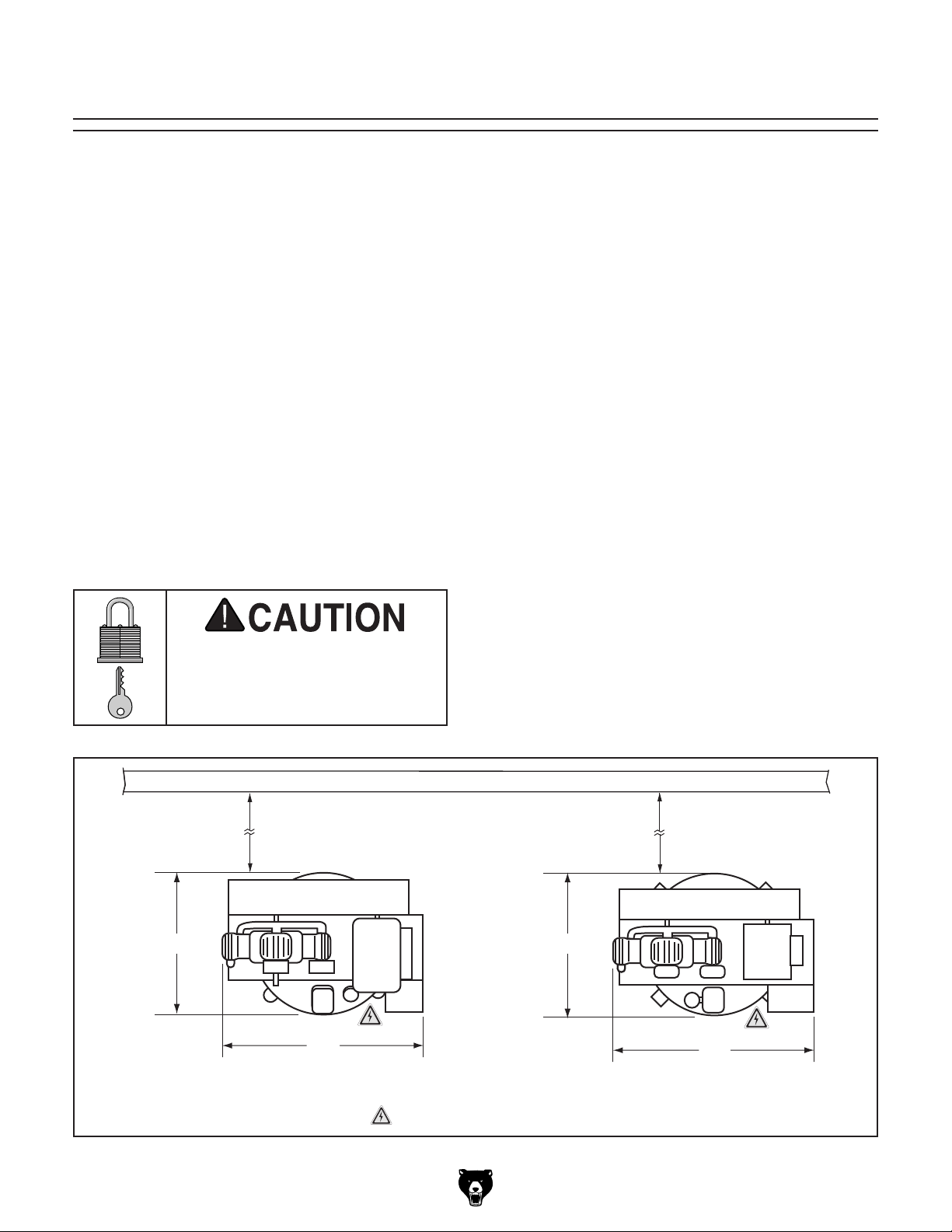
or remove doors/covers as required by the maintenance and service described in this manual.
See below for required space allocation.
Physical Environment
Extreme conditions for this type of machinery are
Place this machine near an existing power source.
other hazards. Make sure to leave enough space
Shadows, glare, or strobe effects that may distract
Machine Data Sheet for the weight
Children or untrained people
may be seriously injured by
this machine. Only install in an
access restricted location.
Min. 18" from
Obstructions
The physical environment where the machine is
operated is important for safe operation and longevity of machine components. For best results,
operate this machine in a dry environment that is
free from excessive moisture, hazardous chemicals, airborne abrasives, or extreme conditions.
generally those where the ambient temperature
range exceeds 41°–104°F; the relative humidity
range exceeds 20%–95% (non-condensing); or
the environment is subject to vibration, shocks,
or bumps.
Electrical Installation
Make sure all power cords are protected from
traffic, material handling, moisture, chemicals, or
around machine to disconnect power supply or
apply a lockout/tagout device, if required.
Lighting
Lighting around the machine must be adequate
enough that operations can be performed safely.
or impede the operator must be eliminated.
Wall
Min. 18" from
Obstructions
Model G0942/G0943 (Mfd. Since 03/21)
32"
40"
G0942
Figure 15. Minimum working clearances.
31"
=
Electrical Connection
42"
G0943
-17-

Lifting & Placing
HEAVY LIF T!
Straining or crushing injury
may occur from improperly
lifting machine or some of
its parts. To reduce this risk,
get help from other people
and use a forklift (or other
lifting equipment) rated for
weight of this machine.
Use lifting equipment rated for at least 1200 lbs.
to lift machine off the pallet and onto a suitable
location, then secure the machine to the shop
floor.
The air compressor must be located at least
18 inches from the nearest wall as described
in Additional Safety for Air Compressors on
Page 12.
Remove top and sides of crate from shipping
2.
pallet.
Unbolt machine from pallet.
3.
4. Place lifting sling under machine saddle (see
Figure 16), then attach sling securely to fork-
lift (or other power lifting equipment).
Note: Be sure sling does not put pressure on
exhaust tube, discharge line, motor, pump, or
belt guard or they can become damaged from
force while lifting.
Lifting
Sling
Before anchoring the machine to the floor, you
should also consider how you plan to design the
air delivery system (see Distribution System
Design on Page 26).
To lift and place machine:
1. Place pallet near final machine mounting
location.
Machine Saddle
Figure 16. Example of lifting sling placed under
machine saddle.
With another person to help steady machine,
5.
lift machine just enough to clear pallet and
any floor obstacles, then place machine in its
final position on shop floor.
-18-
Model G0942/G0943 (Mfd. Since 03/21)

Anchoring to Floor
Lag shield anchors with lag screws (see below)
are a popular way to anchor machinery to a concrete floor, because the anchors sit flush with the
floor surface, making it easy to unbolt and move
the machine later, if needed. However, anytime
local codes apply, you MUST follow the anchoring
methodology specified by the code.
Before the machine can be connected to the
power source, an electrical circuit and connection device must be prepared per the POWER
SUPPLY
setup instructions in this manual must be complete to ensure that the machine has been assembled and installed properly. The disconnect switch
installed by the electrician (as recommended) is
the primary means for disconnecting or connecting the machine to the power source.
Number of Mounting Holes ............................ 4
Diameter of Mounting Hardware
.................5⁄8"
Power Connection
Anchoring machinery to the floor prevents tipping
or shifting and reduces vibration that may occur
during operation, resulting in a machine that runs
slightly quieter and feels more solid. Since this
machine is extremely top heavy, anchoring it
to the floor will also prevent injury and property
damage.
If the machine will be installed in a commercial or
workplace setting, or if it is permanently connected (hardwired) to the power supply, local codes
may also require that it be anchored to the floor.
Anchoring to Concrete Floors
section in this manual; and all previous
Connecting power supply wires to machine
without first disconnecting power supply
may result in serious injury or death.
Connecting Incoming Power Wires
Tools Needed Qty
Flat Head Screwdriver 1⁄4" .................................. 1
Phillips Head Screwdriver #2
To connect incoming power wires:
............................ 1
Lag Screw
Flat Washer
Machine Base
Concrete
Figure 17. Popular method for anchoring
machinery to a concrete floor.
IMPORTANT: DO NOT tighten lag screws so
much that they may cause stress to the tank.
Tip: Install vibration pads between the lag screws
and floor to further cut down on vibration and
noise.
Model G0942/G0943 (Mfd. Since 03/21)
Lag Shield Anchor
Drilled Hole
1. DISCONNECT POWER SUPPLY WIRES
OR LOCK DISCONNECT SWITCH BOX IN
OFF POSITION!
Turn lock screw shown in Figure 18 90˚
2.
counterclockwise to remove magnetic switch
cover.
Magnetic
Switch
Cover
Cover
Lock Screw
Figure 18. Location of magnetic switch cover
and lock screw (Model G0942 shown).
-19-

Ground
3. Remove (2) screws shown in Figure 19 to
remove strain relief clamp, then insert incoming power conduit through strain relief.
G0943 230V Only: Connect incoming power
wires to 1/L1, 3/L2, 5/L3, and ground terminals shown in Figure 21.
Strain
Relief
Strain Relief
Clamp Screw
(1 of 2)
Figure 19. Location of magnetic switch box
strain relief and clamp screws (Model G0942
shown).
During next step, make sure incoming
ground wire is connected to correct terminal
to ensure machine will be properly grounded
(see "Ground" in Figure 20). An ungrounded
or improperly grounded machine can cause
electrocution if live electrical wires make
contact with parts touched by operator.
Incoming Power
Wires
1/L1 3/L2 5/L3
208-240V
CONTACTOR
EATON
A27SNE30 D1
2/T1 4/T2 6/T3
Figure 21. Incoming power wires connected to
1/L1, 3/L2, 5/L3, and ground terminals for Model
G0943 wired for 230V.
G0943 460V Only: Connect incoming power
wires to 1/L1, 3/L2, 5/L3, and ground terminals shown in Figure 22.
4. G0942 Only: Connect incoming power wires
to 1L1, 3L2, and ground terminals shown in
Figure 20.
Incoming Power Wires
1L1
3L2
A113NO
Figure 20. Incoming power wires connected to
1L1, 3L2, and ground terminals for Model G0942.
Incoming Power
Wires
1/L1 3/L2 5/L3
460V
CONTACTOR
EATON
C25DNC325 E1
2/T1 4/T2 6/T3
Figure 22. Incoming power wires connected to
1/L1, 3/L2, 5/L3, and ground terminals for Model
G0943 wired for 460V.
-20-
Model G0942/G0943 (Mfd. Since 03/21)

5. Install strain relief clamp with screws removed
Once assembly is complete, test run the machine
to ensure it is properly connected to power and
safety components are functioning correctly.
If you find an unusual problem during the test run,
immediately stop the machine, disconnect it from
power, and fix the problem BEFORE operating the
machine again. The
table in the
SERVICE section of this manual can help.
DO NOT start machine until all preceding
setup instructions have been performed.
Operating an improperly set up machine
Move the disconnect switch handle to the ON
position, as illustrated below. The machine is now
connected to the power source.
Move the disconnect switch handle to the OFF
position, as illustrated below. The machine is now
disconnected from the power source.
Note:
Lock the switch in the OFF position to
restrict others from starting the machine.
Serious injury or death can result from
in Step 3 to clamp incoming power conduit in
place.
Install magnetic switch cover.
6.
We do not recommend connecting G0943
to a phase converter to supply 3-phase
power as it could damage or decrease life of
sensitive electrical components.
Test Run
Troubleshooting
Connecting to Power Source
Figure 23. Connecting power to machine.
Disconnecting from Power Source
The Test Run consists of verifying the following: 1)
The compressor oil level is sufficient, 2) the motor
powers up and runs correctly, 3) the 3-phase
power supply polarity is correct (Model G0943
only), 4) the pump safety relief valve works correctly (Model G0942 only), 5) the motor and pump
turn OFF when the cut-out pressure is reached,
and 6) the tank safety relief valve works correctly.
using this machine BEFORE understanding
its controls and related safety information.
DO NOT operate, or allow others to operate,
machine until the information is understood.
Figure 24. Disconnecting power from machine.
Model G0942/G0943 (Mfd. Since 03/21)
may result in malfunction or unexpected results that can lead to serious injury,
death, or machine/property damage.
Eye injury hazard! Always
wear safety glasses when
handling pressurized air
system.
-21-

To test run machine:
Check oil level (refer to Lubrication begin-
1.
ning on Page 33 for instructions).
Clear all setup tools away from machine.
2.
3. Move pressure switch lever to OFF position
(see Figure 25).
G0942 G0943
Pressure
Switch
Lever
Pressure
Switch
Lever
5.
Turn output port shut-off valve handle all
the way counterclockwise to open (see
Figure 27).
Shut-Off
Valve Handle
Figure 27. Shut-off valve handle in
open position.
6. Connect machine to power supply.
Figure 25. Location of pressure switch controls.
4. Turn drain valve handle to open position to
open drain valve (see Figure 26).
Drain Valve
Handle
Drain Valve
Handle
G0942 G0943
Figure 26. Drain valve handle in open position.
7. Move pressure switch lever to AUTO/ON
position to turn machine ON and verify motor
operation.
Motor should run smoothly and without
unusual problems or noises.
— For G0942: Proceed to Step 13.
— For G0943: Verify that motor pulley, pump
flywheel, and V-belt rotate clockwise when
viewed from front of machine. If they
rotate clockwise, power supply polarity is
correct, proceed to Step 14. If they rotate
counterclockwise, proceed to Step 8.
Move pressure switch lever to OFF position.
8.
9. DISCONNECT MACHINE FROM POWER!
-22-
Model G0942/G0943 (Mfd. Since 03/21)

10. Turn lock screw shown in Figure 28 90˚
counterclockwise to remove magnetic switch
cover.
Magnetic
Switch
Cover
Cover
Lock Screw
G0943 460V Only: Swap black wire connect-
ed to 1/L1 terminal with red wire connected to
3/L2 terminal on contactor (see Figure 30).
Red 3/L2
Wire
Connection
1/L1 3/L2 5/L3
Figure 28. Location of magnetic switch cover
and lock screw.
11. G0943 230V Only: Swap black wire connected to 1/L1 terminal with white wire connected
to 3/L2 terminal on contactor (see Figure 29).
White 3/L2
Wire
Connection
1/L1 3/L2 5/L3
Black 1/L1
208-240V
Wire
Connection
CONTACTOR
EATON
A27SNE30 D1
2/T1 4/T2 6/T3
Figure 29. Location of black 1/L1 and white 3/L2
wire (wired for 230V operation).
Black 1/L1
460V
Wire
Connection
CONTACTOR
EATON
C25DNC325 E1
2/T1 4/T2 6/T3
Figure 30. Location of black 1/L1 and red 3/L2
wire (wired for 460V operation).
12.
Install magnetic switch cover and reconnect
machine to power, then repeat Step 7.
Do not touch compressor
head or discharge line
during use or immediately
after compressor is active.
These hot parts may cause
burns.
Releasing air through safety relief valve
can be loud. Protect hearing with ANSIapproved ear protection in following step.
Model G0942/G0943 (Mfd. Since 03/21)
-23-

13. G0942 Only: While pump is running, slowly
pull pump safety relief valve ring to bleed
pressure from pump (see Figure 31).
— If machine turns OFF when tank pressure
reaches cut-out pressure (175 PSI), then
safety feature of check valve is working
correctly. Proceed to Step 17.
Pump Safety
Relief Valve
Figure 31. Location of G0942 pump safety relief
valve.
— If pump safety relief valve bleeds pres-
sure, and air stops leaking when ring is
released, then safety relief valve is working correctly. Proceed to Step 14.
— If safety relief valve is stuck or leaks
after releasing ring, immediately turn OFF
machine and disconnect it from power.
Safety relief valve must be replaced before
using machine.
— If machine does not turn OFF when tank
pressure reaches cut-out pressure, then
immediately turn OFF machine and disconnect it from power. Safety feature of
check valve is NOT working properly and
must be replaced before using machine.
Releasing air through safety relief valve
can be loud. Protect hearing with ANSIapproved ear protection in following step.
17. Turn machine OFF and slowly pull tank safety
relief valve ring to bleed pressure from tank
(see Figure 33).
Tank Safety
Relief Valve
Ring
After running compressor for 20 minutes,
14.
move pressure switch lever to OFF position
to turn machine OFF.
Turn drain valve handle and shut-off valve
15.
handle to closed position.
Turn machine ON and observe tank pressure
16.
gauge (see Figure 32) while tank fills.
G0942 G0943
Tank
Pressure Gauge
Tank
Pressure Gauge
Figure 32. Location of tank pressure gauge.
Figure 33. Location of tank safety relief valve
ring (Model G0942 shown).
— If tank safety relief valve bleeds pres-
sure, and air stops leaking when ring is
released, then safety relief valve is working correctly. Proceed to Step 18.
— If safety relief valve is stuck or leaks
after releasing ring, immediately turn OFF
machine and disconnect it from power.
Safety relief valve must be replaced before
using machine.
Open drain valve to drain moisture from tank.
18.
19. Recheck oil level before proceeding with
operations.
-24-
Model G0942/G0943 (Mfd. Since 03/21)
SECTION 4: OPERATIONS
The purpose of this overview is to provide the novice machine operator with a basic understanding
of how the machine is used during operation, so
the
discussed later
in this manual
Due to the generic nature of this overview, it is
not intended to be an instructional guide. To learn
more about specific operations, read this entire
manual,
training from experienced
machine operators
outside of this manual by reading "how-to" books,
trade magazines, or websites.
To reduce your risk of
serious injury, read this
entire manual BEFORE
Eye injury hazard! Always
wear safety glasses when
Operation Overview
machine controls/components
are easier to understand.
seek additional
, and do additional research
3. Puts on any additional personal protective
equipment required by operation and attachment tool.
Connects machine to power and turns it ON.
4.
Allows machine to run until cut-out pressure
5.
has been reached and tank is full.
Adjusts in-line regulator in air supply line to 0
6.
PSI.
Connects air hose to quick-connect coupler
7.
in air delivery system.
Connects attachment air tool to air hose.
8.
9. Opens output port shut-off valve to release
air into distribution system.
using machine.
using this machine.
Do not touch compressor
head or discharge line
during use or immediately
after compressor is active.
These hot parts may cause
To complete a typical operation, the operator
does the following:
Puts on safety glasses.
1.
2. Pulls safety valve ring(s) to test valve(s) and
clear any obstructions.
Model G0942/G0943 (Mfd. Since 03/21)
burns.
Adjusts in-line regulator so line pressure at
10.
hose is lower than or equal to air tool rating.
While being careful not to create a tripping
11.
hazard with hose, performs operation.
Closes output port shut-off valve and bleeds
12.
air from delivery system.
Turns compressor power OFF and discon-
13.
nects it from power.
Uses tank safety relief valve to reduce tank
14.
pressure to less than 10 PSI.
Opens drain valves to drain any condensa-
15.
tion from tank and delivery system, then
closes drain valves.
If you are not experienced with this type
of machine, WE STRONGLY RECOMMEND
that you seek additional training outside of
this manual. Read books/magazines or get
formal training before beginning any projects. Regardless of the content in this section, Grizzly Industrial will not be held liable
for accidents caused by lack of training.
-25-
Distribution System
Design
Once you know how large your system will be,
and what components you will install, choose a
material for the distribution lines. Stainless steel,
copper, and aluminum can withstand the force
and heat of compressed air.
When designing your air distribution system,
consider how many and what types of tools you
intend to use, and what requirements those tools
will have (see Connecting Air Tools on Page 29).
The length of hose you use to connect tools to the
system may affect how far the system needs to
reach (see Choosing Air Hoses on Page 28).
Determine what methods you will use to remove
moisture, oil, and dirt from the compressor air (see
Distribution System Components on Page 27).
Plan to add a regulator for each supply line, and
determine if you will need to add a lubricator.
Installing quick-connect couplers will allow you to
easily connect and disconnect air tools.
The compressor must be anchored at least 18
inches away from the nearest wall and 20 inches
away from any combustible spraying operations.
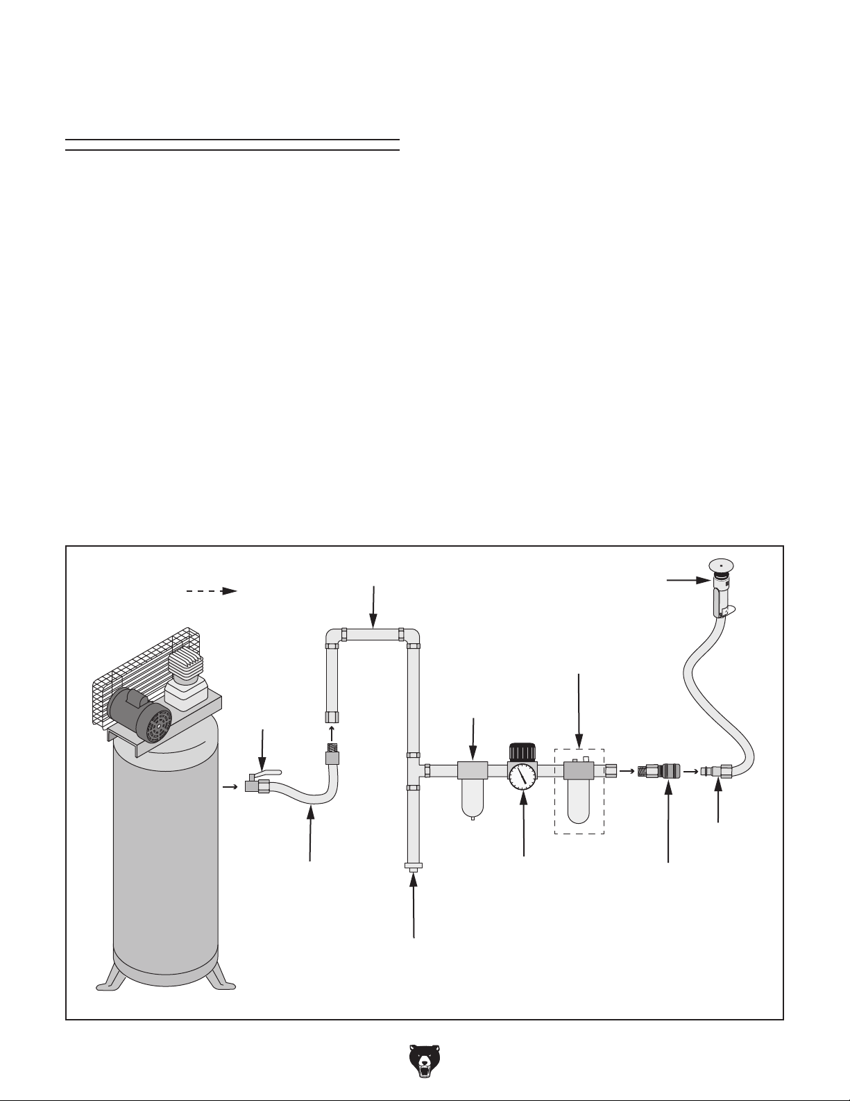
Air Supply Line
Air Flow
Shut-Off
Valve
Decide how you will route the distribution lines.
Forcing air flow up, against gravity, after it leaves
the compressor, will naturally prevent moisture
from proceeding through the line and reaching
your tool.
Build your system using your desired pipes, fittings, filters, drains, and regulators, then use a
flexible conduit or coupling to connect your air
compressor. This will decrease any structural
pressure on the tank and distribution pipes that
could stress and damage the components. The
Model G0942/G0943 has a shut-off valve to stop
the airflow when attaching tools or servicing individual components.
Further information about air distribution systems
is out of the scope of this manual. Consult outside
resources and books for more suggestions.
Air Tool
Lubricator
(For Lubricated
Air Tool
In-Line
Air/Moisture
Filter
Lines Only)
-26-
Air Compressor
Flexible
Coupling
Drain Leg
Figure 34. Typical air distribution system.
Regulator
Model G0942/G0943 (Mfd. Since 03/21)
Hose
w/Plug
Quick-Connect
Coupler

Distribution System
Components
The distribution system is what delivers the air
from your compressor to the tool you wish to use.
Air delivery components can be damaged if dirt,
oil, or water enter the air supply line. An air distribution system allows you to clean the air, remove
moisture and heat, and regulate the pressure,
all after the air leaves the compressor tank and
before it enters the air tool.
Air Dryer
Before the air reaches an air tool, it must be dried
by some method or another. One option is to
install a moisture trap, which provides a place for
moisture to collect where it can be easily drained
(see Figure 34 on Page 26).
Another option is to install a moisture filter (see
Figure 35). The filter can be cleaned and replaced,
while any accumulated moisture is drained from a
drain valve. Many of these can filter dirt, oil, and
moisture at the same time.
Air In
Air Out
Filter
Element
Air Filter
Ensuring clean air reaches your air tools will also
extend tool life. If your method of moisture removal does not also filter out oil, dirt, and debris, we
recommend also adding an in-line air filter (see
Figure 36).
Regulator
(Optional)
Air In Air Out
Filter
Element
Drain Valve
Figure 36. Example of an air filter.
Regulator
A regulator (see Figure 37) is what adjusts the
air supply line to your desired operating pressure.
The operating pressure should always be equal to
or less than the pressure that your air tool is rated
for. An air tool recommended for 70 PSI should
never be connected to a hose or system set to
higher than that operating pressure, as the tool or
valves could burst. A regulator allows tools with a
lower rating than the system to still be attached,
because the line can be adjusted to a safe level.
Drain Valve
Figure 35. Example of a moisture filter.
The last option is to install an actual air dryer. These
are better suited for large industrial applications.
Model G0942/G0943 (Mfd. Since 03/21)
Air In
Outgoing Air
PSI Gauge
Air Out
Figure 37. Example of a regulator.
Regulator
Knob
-27-

Lubricator
After water, debris, and oil from the compressor
and environment have been removed, some air
tools require lubrication be added back into the
system to perform their job properly. Air line oil
can be added directly to the tool before and during
use, or an in-line lubricator (see Figure 38) can be
added to the air supply line so oil is added automatically. Only use a lubricator for tools that
require it. Adding lubrication to a paint sprayer,
for instance, can contaminate the tool and paint
and prevent a proper application.
Filter/Regulator
(Optional)
Fill Cap
Lubrication
Rate
Control Knob
Choosing Air Hoses
There are many options when it comes to hoses.
The most important aspects for an air compressor
are going to be length, diameter, and fittings. The
material of the hose is also an important consideration, but this will depend more on your application and preference.
Length
Consider your applications before deciding on a
hose length. Longer hoses, or hose connections
to extend hose length, can increase your mobility,
but will probably result in some pressure loss.
If your work area will be small, you may be able
to use a shorter hose without stretching the hose.
Never put any unnecessary stress on the hose,
valves, fittings, or air delivery system.
Air In
Figure 38. Example of an in-line lubricator.
Air Out
Lubrication
Reservoir
An air compressor becomes very hot during operation, and the pressure switch and motor often
produce sparks. Some applications, like spraying
or sanding, involve flammable material that create a fire or combustion hazard when they are
performed too close to a compressor. The hose
length must allow for the air compressor to remain
at least 20 feet away from the operation.
Diameter
A larger inner diameter will allow for higher airflow
delivery. Refer to Airflow Delivery (CFM) for
more information. The higher CFM a tool requires,
the larger the inner diameter of the hose will need
to be (see Figure 39).
Airflow Delivery Required ID
0–3 CFM
3.1–5.9 CFM
6+ CFM
Figure 39. Recommended hose inner diameters.
1
⁄4" (3mm)
1
⁄4"–3⁄8" (3mm–10mm)
3
⁄8"+ (10mm+)
-28-
Model G0942/G0943 (Mfd. Since 03/21)

Fittings
Many hoses come with fittings installed (see
Figure 40). The simplest option is to find a hose
with two fittings: one that matches the air line
output port, and one that matches your intended
attachment tool. If the hose does not match the
port, a coupler may be needed.
Fitting
Figure 40. Air hose with fitting installed.
You will need to determine the size of the fittings and whether they are male or female (see
Figure 41). A male fitting can only attach to a
female fitting, and vice versa. There are also a
number of coupler/plug styles on the market, so
be sure the two match or you will likely not have
an airtight connection.
Male
Coupler
Figure 41. Example of male and female fittings.
Male
Plug
Female
Coupler
Female
Plug
Connecting Air Tools
There are various air tools that can be connected
to your air compressor by means of the air distribution system, and the setup will vary little across
tools, but there are a couple things to keep in
mind before connecting a tool or hose.
Airflow Delivery (CFM)
The first consideration when choosing an air tool
is whether or not the air delivery is compatible with
your compressor. Smaller compressors, capable
of less than 5 CFM, only supply enough pressure
for smaller air tools like nailers, staplers, chippers,
chisels, grinders, sanders, tire inflators, and paint
sprayers. Air hammers, impact wrenches, impact
hammers, and blow guns will probably require a
larger compressor capable of 10-110 CFM.
Duty Cycle
The duty cycle of your compressor will also have
an effect on how efficient the airflow delivery is.
Refer to Figure 42 for some common duty cycles
and what they mean.
Compressor can be used for up to half
50/50
60/40
75/25
85/15
100
Compressing air produces a lot of heat, so the
pump and motor require some resting time in
order to cool down. The "cycle" of an air compressor refers to how long it takes for the compressor
to be used and subsequently cooled. The duty
cycle dictates what percentage of the cycle you
can spend using air before it must rest.
of its cycle (spends same amount of
time resting as it does working).
Compressor can be used for up to 60%
of its cycle; spends 40% of time resting.
Compressor can be used for up to 75%
of its cycle; spends 25% of time resting.
Compressor can be used for up to 85%
of its cycle; spends 15% of time resting.
Compressor does not need to rest.
Engine/motor has a cooling component
allowing for constant air delivery.
Figure 42. Common duty cycles.
Model G0942/G0943 (Mfd. Since 03/21)
-29-
Connecting Air Tool
Use the following steps as a guide for attaching
an air tool. As there are a wide variety of tool and
hose options, your connections may differ slightly
from this simple outline.
Items Needed Qty
Air Too l .............................................................. 1
Air Hose
Additional Connection Fittings
............................................................. 1
........... As Needed
Eye injury hazard! Always
wear safety glasses when
handling pressurized air
system.
Disconnecting Air Tool
Eye injury hazard! Always
wear safety glasses when
handling pressurized air
system.
Pressurized air escaping through valves/
fittings can be extremely loud. Protect
hearing with ANSI-approved hearing
protection in following steps.
To disconnect air tool:
Adjust in-line regulator in air supply line to 0
1.
PSI.
Always wear personal protective equipment
required by air tool you are using. Pneumatic
grinders, sanders, paint sprayers, etc.,
require respirator to protect against longterm respiratory damage. Prolonged
exposure to loud tools can result in hearing
loss without the use of hearing protection.
To connect air tool:
Adjust in-line regulator in air supply line to 0
1.
PSI.
Insert air hose male plug into quick-connect
2.
coupler.
Connect other end of hose to air tool.
3.
Note: Refer to air tool instructions for speci-
fications, method of connection, and proper
use of tool.
Disconnect air tool from hose.
2.
3. Push coupler sleeve away from plug to
release hose plug.
Note: Air will escape when connection is bro-
ken if air supply line is still pressurized.
-30-
Model G0942/G0943 (Mfd. Since 03/21)

ACCESSORIES
Installing unapproved accessories may
order online at www.grizzly.com or call 1-800-523-4777
SECTION 5: ACCESSORIES
cause machine to malfunction, resulting in
serious personal injury or machine damage.
To reduce this risk, only install accessories
recommended for this machine by Grizzly.
NOTICE
Refer to our website or latest catalog for
additional recommended accessories.
Basic Eye Protection
T32323—Woodturners Face Shield
T32401—EDGE Brazeau Safety Glasses, Clear
T32402—EDGE Khor G2 Safety Glasses, Tint
T32404—EDGE Mazeno Safety Glasses, Clear
T32323 T32401
T32079—Paint & Body Respirator Kit - Medium
T32080—Paint & Body Respirator Kit - Large
This kit includes (1) silicone rubber half mask
respirator, (2) T32088 organic vapor cartridges,
(2) P100 pancake filters with organic vapor/AG
nuisance odor relief, and (4) P95 particulate filter
pads and filter retainers.
T32402
Figure 44. Assortment of basic eye protection.
T28041—Primrose Air Compressor Oil
This oil is a blend of the highest quality solvent
refined, paraffinic, and naphthenic petroleum mineral oils and additives which prevent rust and
oxidation. It's formulated for clean, trouble-free
air compressor lubrication and effective control of
carbon deposits for longer life. 1 quart size.
T32404
Figure 43. Paint & Body Respirator Kit.
Figure 45. T28041 236 Primrose Plus Air
Compressor Oil.
Model G0942/G0943 (Mfd. Since 03/21)
-31-

SECTION 6: MAINTENANCE
Schedule
Compressor will turn ON
automatically when pressure switch is set to ON
or AUTO. To reduce risk of
shock/accidental startup,
always disconnect machine
from power before adjustments, maintenance, or
service.
Eye injury hazard! Always
wear safety glasses when
maintaining pressurized air
system.
For optimum performance from this machine, this
maintenance schedule must be strictly followed.
Ongoing
To minimize your risk of injury and maintain proper
machine operation, shut down the machine immediately if you ever observe any of the items below,
and fix the problem before continuing operations:
• Low oil level.
• Damaged safety relief valve, pressure switch,
or drain valve.
Worn or damaged wires, cords, and plugs.
•
Tank rust/corrosion.
•
Any other unsafe condition.
•
Do not touch compressor
head or discharge line
during use or immediately
after compressor is active.
These hot parts may cause
burns. Allow compressor
to cool before handling.
Do not use flammable
cleanser to clean machine.
Compressor components
often produce sparks that
could ignite once machine
is connected to power and
turned ON.
Daily Maintenance
• Open drain valve to drain any condensation.
• Check oil level.
• Test function of safety relief valve(s) and
clear any obstructions.
Releasing air through safety relief valve or
drain valve can be extremely loud. Protect
hearing with ANSI-approved hearing
protection when testing/draining valves.
Weekly Maintenance
• Check air filters.
• Clean/vacuum dust buildup off compressor.
Monthly Maintenance
• Check V-belt tension, damage, or wear.
Quarterly (3 Month/300 Hour) Maintenance
• Change compressor oil.
-32-
Semi-Annual (6 Month) Maintenance
• Check hoses/connections for leaks. If soapy
water at suspected leak creates bubbles, air
is escaping. Repair or replace affected parts.
Model G0942/G0943 (Mfd. Since 03/21)

Draining Tank
Lubrication
Some water may accumulate in the tank and air
delivery system depending on usage and humidity. Drain water from the tank, and any attached
delivery system, daily to increase the lifespan of
the compressor and air tools and to prevent tank
and pipe corrosion.
To drain tank:
DISCONNECT MACHINE FROM POWER!
1.
Releasing air through safety relief valve
can be extremely loud. Protect hearing
with ANSI-approved hearing protection in
following step.
2. Use tank safety relief valve to reduce tank
pressure to less than 10 PSI.
Move drain valve handle to open position
3.
(see Figure 46) to open drain valve.
The oil level in the Model G0942/G0943 should
be checked daily to prevent overheating and damage to the compressor. Change the oil every 300
hours of use.
Checking Oil Level
Item Needed Qty
Model T28041 or SAE 30 Equiv. ....... As Needed
To check oil level:
Check oil sight glass (see Figure 47). Oil
1.
level should be kept between bottom and top
of red circle.
Oil Fill
Plug
Oil Sight
Glass
Drain Valve
Handle
Drain Valve
Handle
G0942 G0943
Figure 46. Drain valve handle in open position.
Figure 47. Location of oil sight glass and oil fill
plug (Model G0942 shown).
— If oil level is between top and bottom of red
circle, no additional oil is needed.
— If oil level is below bottom of red circle,
proceed to Step 2.
DISCONNECT MACHINE FROM POWER!
2.
3. Remove oil fill plug (see Figure 47).
Add compressor oil until oil level is between
4.
bottom and top of red circle, then install fill
plug.
Model G0942/G0943 (Mfd. Since 03/21)
-33-

Changing Oil
Items Needed Qty
Drain Pan ........................................................... 1
Shop Rags
Wrench or Socket
Wrench or Socket 14mm (G0943 Only)
Wire Brush
Thread Sealing Tape
Model T28041 or SAE 30 Equivalent
G0942 .................................................1.5 Qt.
G0943 ................................................... 4 Qt.
......................................... As Needed
......................................................... 1
11
⁄16" (G0942 Only) ................ 1
............ 1
......................... As Needed
Checking Air Filters
The air filters help prevent impurities and dust
from entering the compressor and reduce noise. A
dirty filter will result in a less efficient system and
could become a fire hazard.
Items Needed Qty
Replacement Filters........................... As Needed
To change oil:
DISCONNECT MACHINE FROM POWER!
1.
2. Remove oil fill plug (see Figure 48).
Place drain pan under oil drain plug, then
3.
remove oil drain plug (see Figure 48).
Oil Fill
Plug
Oil Sight
Glass
Oil Drain
Plug
To check air filters:
DISCONNECT MACHINE FROM POWER!
1.
Releasing air through safety relief valve
can be extremely loud. Protect hearing
with ANSI-approved hearing protection in
following step.
2. Use tank safety relief valve to reduce tank
pressure to less than 10 PSI.
G0942 Only: Rotate filter cap shown in
3.
Figure 49 counterclockwise to remove filter
cap and access filter.
Cap
Figure 48. Location of oil fill plug, oil drain plug,
and oil sight glass (Model G0942 shown).
4.
Clean drain plug threads.
5. When oil is fully drained, wrap drain plug
threads with thread sealing tape, then install
drain plug.
Add compressor oil until oil level is between
6.
bottom and top of red circle on oil sight glass
(see Figure 48), then install fill plug.
-34-
Figure 49. Location of Model G0942 filter cap.
Model G0942/G0943 (Mfd. Since 03/21)

— If filter is fairly clean and there has not
been a drop in efficiency of compressor,
replace cap. No replacement is required.
Adjusting
Belt Tension/
— If filter is dirty or clogged, or there has
been a drop in efficiency of compressor,
replace cap. Proceed to Step 4.
G0943 Only: Remove wing nut shown in
Figure 50 to remove filter cap and access
filter.
Cap
Figure 50. Location of Model G0943 filter cap
and wing nut.
— If filter is fairly clean and there has not
been a drop in efficiency of compressor,
replace cap. No replacement is required.
— If filter is dirty or clogged, or there has
been a drop in efficiency of compressor,
replace cap. Proceed to Step 4.
G0942 Only: Replace old filter with
4.
new filter element (refer to Part #64 on
Page 52), then install filter cap.
G0943 Only: Replace old filter with
new filter element (refer to Part #63 on
Page 54), then install filter cap.
Pulley Alignment
The V-belt transfers power from the motor to the
compressor pump. To ensure efficient transfer of
power, make sure the V-belt is always properly
tensioned and in good condition. If the V-belt is
worn, cracked, or damaged, replace it.
Pulley alignment is another important factor in
power transmission and belt life. The motor pulley should be parallel to the pump flywheel and
they should be in the same plane (coplanar) for
optimum performance.
The belt tension and motor pulley alignment are
both adjusted by repositioning the motor on the
saddle. Be advised that these items cannot be
adjusted independently.
Items Needed Qty
Wrenches or Sockets 13, 14mm, 9⁄16" ..........1 Ea.
Open or Closed-End Wrench 13mm
Replacement Belt
Another Person
Straightedge 36"
Measuring Tape
To adjust belt tension/pulley alignment:
1.
DISCONNECT MACHINE FROM POWER!
Remove hex nut, lock washer, and hex bolt
2.
shown in Figure 51.
Note: Model G0942 has an additional (2)
fender washers on hex bolt.
.............................. As Needed
.................................................. 1
................................................ 1
................................................. 1
................. 1
Repeat Step 3 for remaining filter(s).
5.
Model G0942/G0943 (Mfd. Since 03/21)
-35-

Pulley
Flywheel
1
⁄4"
Deflection
Figure 51. Location of belt guard bracket
fasteners.
Remove (4) hex bolts and flat washers shown
3.
in Figure 52 to remove belt guard.
Belt Guard
x 4
Figure 52. Location of belt guard and
fasteners (Model G0943 shown).
Figure 53. Checking V-belt tension.
— If V-belt is not cracked, torn, excessively
1
worn, or damaged, and there is
⁄4" of
deflection, belt does not need to be adjusted or replaced. Proceed to Step 10.
— If V-belt is cracked, torn, excessively worn,
1
damaged, or there is not
⁄4" of deflection,
proceed to Step 5.
Loosen (4) hex nuts on hex bolts shown in
5.
Figure 54, then push motor towards pump to
release belt tension.
— If V-belt is damaged, replace belt (refer to
Part #126 on Page 56 for G0942 or Page
58 for G0943).
Belt, pulley, and flywheel will be hot after
operation. Allow them to cool before
handling.
4. Press belt in center to check belt tension. Belt
is correctly tensioned when there is approxi-
1
mately
⁄4" deflection when it is pushed with
moderate pressure, as shown in Figure 53.
-36-
x 4
V-Belt
Figure 54. Location of belt tension components
(Model G0943 shown).
Model G0942/G0943 (Mfd. Since 03/21)
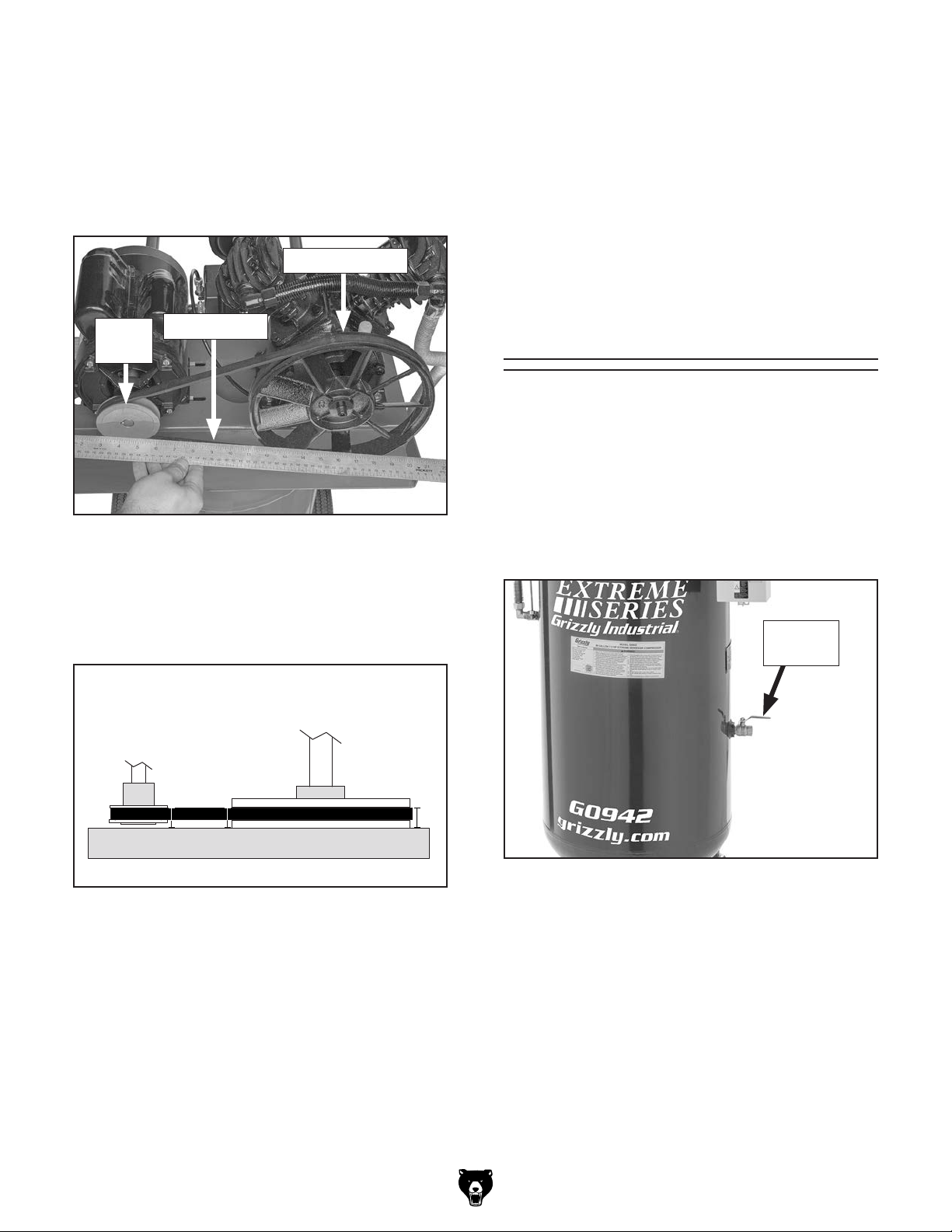
6. Have another person push motor away from
pump so there is approximately 1⁄4" deflection,
then tighten hex nuts from Step 5.
Place straightedge so it is flush against pump
7.
flywheel and it extends over motor pulley
(see Figure 55).
Pump Flywheel
Loosen (4) hex nuts from Step 5 and, while
9.
maintaining correct belt tension, have assistant adjust motor until pulley and flywheel are
coplanar, then tighten hex nuts to secure.
Install belt guard with flat washers and hex
10.
bolts removed in Step 3.
Install hex nut, washer(s), and hex bolt
11.
removed in Step 2.
Motor
Pulley
Figure 55. Example of using straightedge to
8. Measure distance between straightedge and
V-belt at "A", "B", and "C" locations shown in
Figure 56.
Motor
Pulley
Straightedge
check pulley alignment.
Pump
Flywheel
Checking for Leaks
Air leaks will cause low air output and increase
the time the compressor must run. Use the following method to check the valves and fittings on
your compressor and air delivery system.
Checking for Leaks
1. Close output port shut-off valve (see
Figure 57).
Shut-Off
Valve
A
Figure 56. Distances to measure.
— If measurements are all within 1⁄16" of each
other, pulley and flywheel are coplanar
and do not need to be adjusted. Proceed
to Step 10.
— If measurements are not all within 1⁄16" of
each other, pulley and flywheel are not
coplanar. Proceed to Step 9.
Model G0942/G0943 (Mfd. Since 03/21)
B C
Figure 57. Location of shut-off valve.
2. Turn ON compressor and allow tank to fill
until cut-out pressure is reached.
DISCONNECT MACHINE FROM POWER!
3.
4. Listen for sound of air to find possible leak at
compressor.
— If you do not hear air escaping, and pres-
sure in tank does not change, there is no
leak at compressor.
-37-

— If you do hear air escaping, or pressure in
tank drops even with safety relief valve(s)
and drain valve closed, proceed to Step 5.
Spray suspected air leak with soap and water
5.
solution and look for air bubbles.
Fixing Leaks
Items Needed Qty
Wire Brush ......................................................... 1
Thread Sealing Tape or Pipe Dope
To fix leaks:
... As Needed
— If bubbles do not form, repeat at different
location.
— If bubbles do form, refer to Fixing
Leaks to stop compressor leak before
proceeding to check delivery system.
Disconnect any tools and hoses from quick-
6.
connect couplers of delivery system.
Open compressor output port shut-off valve.
7.
Connect compressor to power, turn it ON,
8.
and allow tank and air delivery system to
fill until cut-out pressure of compressor is
reached.
DISCONNECT MACHINE FROM POWER!
9.
10. Listen for sound of air to find possible leak.
— If you do not hear air escaping, and pres-
sure in tank does not change, there is no
leak at delivery system.
— If you do hear air escaping, or pressure in
tank drops even with safety relief valve(s)
and all drain valves closed, proceed to
Step 11.
DISCONNECT MACHINE FROM POWER!
1.
Releasing air through safety relief valve
can be extremely loud. Protect hearing with
ANSI-approved hearing protection while
performing following step.
2. Use tank safety relief valve to reduce tank
pressure to less than 10 PSI.
Open drain valve(s) to relieve any remaining
3.
air.
Remove fitting, valve, conduit, or filter that is
4.
leaking.
Clean threads, apply thread sealing tape or
5.
pipe dope to threads, then re-install part.
Note: If a fitting, valve, conduit, or filter con-
tinues to leak after preceding steps, replace
part.
Spray suspected air leak with soap and water
11.
solution and look for air bubbles.
— If bubbles do not form, repeat at different
location.
— If bubbles do form, refer to Fixing Leaks.
-38-
Model G0942/G0943 (Mfd. Since 03/21)

Machine Storage
All machinery will develop serious rust problems
and corrosion damage if it is not properly prepared
for storage. Use the steps in this section to ensure
that your machine remains in good condition.
To bring machine out of storage, perform the Tes t
Run beginning on Page 21.
2. Use tank safety relief valve to reduce tank
pressure to less than 10 PSI.
Open drain valve to drain any condensation
3.
from tank.
Close output port shut-off valve.
4.
5. Disconnect conduits from output port.
6. Clean machine.
Eye injury hazard! Always
wear safety glasses when
handling pressurized air
system.
Items Needed Qty
Cleaner/Degreaser ............................ As Needed
.................................................. As Needed
Rags
Tarp or Plastic Sheet
To prepare machine for storage:
1. DISCONNECT MACHINE FROM POWER!
Releasing air through safety relief valve
can be extremely loud. Protect hearing with
ANSI-approved hearing protection while
performing following step.
......................................... 1
Do not use a flammable
cleanser to clean machine.
Compressor components
often produce sparks that
could ignite once machine
is connected to power and
turned ON.
7. Close drain valve.
8. Cover machine with tarp or plastic sheet that
will keep out dust and resist liquid or moisture. If machine will be stored in/near direct
sunlight, use cover that will block UV rays.
Model G0942/G0943 (Mfd. Since 03/21)
-39-

Review the troubleshooting procedures in this section if a problem develops with your machine. If you need
the
serial number and manufacture date of your machine before calling.
SECTION 7: SERVICE
replacement parts or additional help with a procedure, call our Technical Support. Note: Please gather
Troubleshooting
Motor & Electrical
Symptom Possible Cause Possible Solution
Machine does
not start, or
power supply
breaker
immediately
trips after
startup.
Machine
stalls or is
underpowered.
1. Tank already pressurized.
2. Incorrect power supply voltage or circuit size.
3. Incoming power wires wired incorrectly.
4. Pressure switch cut-in/cut-out settings have
been adjusted incorrectly.
5. Power supply circuit breaker tripped or fuse
blown.
6. Motor wires connected incorrectly.
7. Thermal overload relay has tripped/at fault.
8. Start capacitor at fault (G0942 only).
9. Centrifugal switch adjustment/contact points
at fault (G0942 only).
10. Contactor not energized/at fault.
11. Wiring broken, disconnected, or corroded.
12. Tripped motor thermal overload; compressor
is exceeding its duty cycle.
13. Check valve components are dirty/damaged.
14. Pressure switch at fault.
15. Motor or motor bearings at fault.
1. Air filter(s) dirty/clogged.
2. Pump/motor have restricted airflow.
3. Belt slipping/pulley misaligned.
4. Motor wires connected incorrectly.
5. Pressure switch cut-in/cut-out settings have
been adjusted incorrectly.
6. Incoming power wires wired incorrectly.
7. Pulley/flywheel slipping on shaft.
8. Tripped motor thermal overload; compressor
is exceeding its duty cycle.
9. Crankcase oil is not correct type.
10. Run capacitor at fault (G0942 only).
11. Contactor not energized/at fault.
1. Motor will not start if tank is fully pressurized.
2. Ensure correct power supply voltage and circuit size
(Page 13).
3. Test for good contacts/correct wiring (Page 46).
4. Adjust settings (Page 44). Do not exceed cut-in/cutout pressures listed on data sheet (Page 6) or inside
pressure switch.
5. Ensure circuit is free of shorts. Reset circuit breaker or
replace fuse.
6. Correct motor wiring connections (Page 46).
7. Reset. Adjust or replace if at fault.
8. Test/replace if at fault.
9. Adjust centrifugal switch/clean contact points. Replace
either if at fault.
10. Test all legs for power; replace if necessary.
11. Fix broken wires or disconnected/corroded
connections (Page 46).
12. Reduce load on compressor and allow longer cool
down periods.
13. Clean/replace check valve components.
14. Turn compressor OFF, disconnect from power, and
empty tank. DO NOT USE until switch is replaced.
15. Replace motor.
1. Replace air filter(s) (Page 34).
2. Clean cylinder fins, motor fan, and vent area.
3. Clean/tension/replace belt (Page 35); ensure pulley is
aligned to pump flywheel (Page 35).
4. Correct motor wiring connections (Page 46).
5. Adjust settings (Page 44). Do not exceed cut-in/cutout pressures listed on data sheet (Page 6) or inside
pressure switch.
6. Test for good contacts/correct wiring (Page 46).
7. Tighten/replace loose pulley/flywheel/shaft.
8. Reduce load on compressor and allow longer cool
down periods.
9. Drain and replace with correct oil (Page 34).
10. Test/repair/replace.
11. Test all legs for power; replace if necessary.
-40-
Model G0942/G0943 (Mfd. Since 03/21)
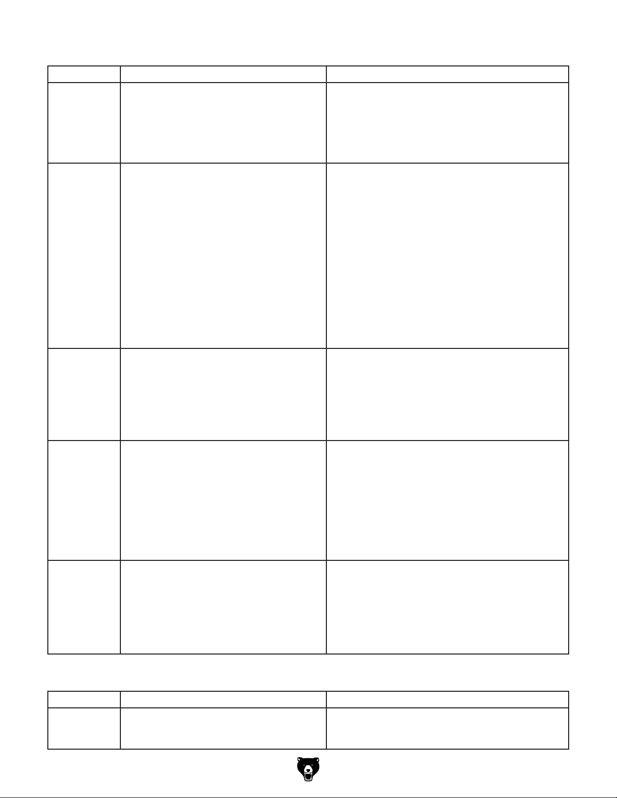
Motor & Electrical (Cont.)
Symptom Possible Cause Possible Solution
Machine
stalls or is
underpowered.
Machine has
vibration or
noisy operation.
Motor pulley
and pump
flywheel do not
rotate clockwise
when viewed
from front
of machine
(G0943 only).
Motor runs
continuously.
Pressure relief
valve stays
open and motor
will not stop
running.
12. Check valve components are dirty/damaged.
13. Centrifugal switch/contact points at fault
(G0942 only).
14. Motor or motor bearings at fault.
15. Worn valves or rings/compressor pump at
fault.
1. Motor or component loose.
2. Loose mounting hardware/feet need shims or
vibration pads.
3. V-belt worn, loose, pulley misaligned, or belt
slapping guard.
4. Pulley/flywheel loose.
5. Motor fan rubbing on fan cover.
6. Centrifugal switch needs adjustment/at fault
(G0942 only).
7. Motor bearings at fault.
8. Compressor pump at fault.
1. Power connections wired out of phase. 1. Correct phase polarity (Page 22).
1. Machine is undersized.
2. In-line regulator(s) needs to be adjusted for
lower airflow delivery.
3. Air leak in tank or delivery pipes.
4. Pressure switch at fault.
1. Pressure switch cut-in/cut-out settings have
been adjusted incorrectly.
2. Pressure switch at fault, unit is trying to
overpressurize tank.
3. Pressure relief valve at fault/relieving
pressure too early.
12. Clean/replace check valve components.
13. Adjust centrifugal switch/clean contact points. Replace
either if at fault.
14. Replace motor.
15. Rebuild/replace.
1. Replace damaged or missing bolts/nuts or tighten if
loose.
2. Tighten fasteners/add shims or vibration pads.
3. Inspect/replace belt (Page 35). Realign pulley to pump
flywheel if necessary (Page 35).
4. Secure pulley/flywheel on shaft.
5. Fix/replace fan cover; replace loose/damaged fan.
6. Adjust/replace if at fault.
7. Test by rotating shaft; rotational grinding/loose shaft
requires bearing replacement.
8. Compressor piston rod/bearing/crankshaft is worn.
Rebuild or replace pump.
1. Use smaller attachment tool(s) or larger air
compressor.
2. Adjust regulator(s) to decrease line PSI.
3. Check air tank, pipes, and all connections for leaks
(Page 37). Do not attempt to repair leaking/damaged
tank, only replace.
4. Turn compressor OFF, disconnect from power, and
empty tank. DO NOT USE until switch is replaced.
1. Adjust settings (Page 44). Do not exceed cut-in/cutout pressures listed on data sheet (Page 6) or inside
pressure switch.
2. Turn compressor OFF, disconnect from power, and
empty tank. DO NOT USE until switch is replaced.
3. Replace.
Operation
Symptom Possible Cause Possible Solution
Air leaks from
pressure
switch.
Model G0942/G0943 (Mfd. Since 03/21)
1. Check valve components are dirty/damaged.
2. Pressure switch at fault.
1. Clean/replace check valve components.
2. Turn compressor OFF, disconnect from power, and
empty tank. DO NOT USE until switch is replaced.
-41-
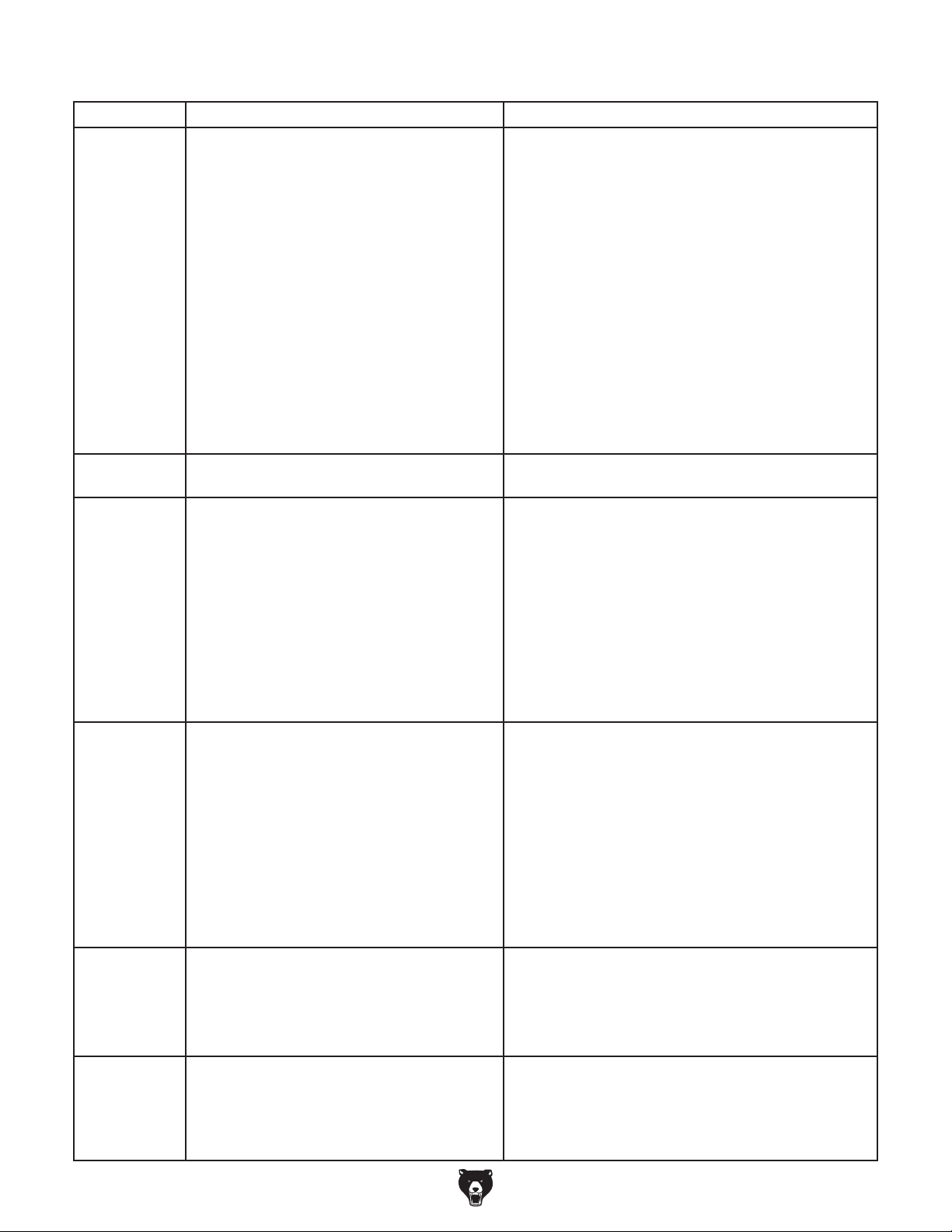
Operation (Cont.)
Symptom Possible Cause Possible Solution
Low pressure
in tank, or
tank pressure
drops after
compressor is
turned OFF.
Air leaks from
air filter(s).
Compressor
does not build
pressure, or
does not reach
full pressure.
Air tools have
oily discharge.
Air tools
have watery
discharge or
get cold and
freeze up with
ice during use.
Air tool has low
supply pressure
but compressor
has sufficient
air pressure.
1. Drain valve or output shut-off valve is open.
2. Air filter(s) dirty/clogged.
3. In-line regulator(s) needs to be adjusted for
lower airflow delivery.
4. Pressure switch cut-in/cut-out settings have
been adjusted incorrectly.
5. Air leak in tank or delivery pipes.
6. Check valve components are dirty/damaged.
7. Pressure relief valve releasing below cut-out
pressure.
8. Gasket(s) leaking.
9. Worn pump piston rings.
1. Check valve components are dirty/damaged.
2. Reed valve(s) not sealing.
1. Drain valve or output shut-off valve is open.
2. Tank needs to be drained.
3. Air filter(s) dirty/clogged.
4. Air leak in tank or delivery pipes.
5. Check valve components are dirty/damaged.
6. Reed valve(s) not sealing.
7. Head gasket or valve body gasket leaking.
8. Worn pump piston rings.
9. Broken crankshaft or connecting rod.
1. Tank needs to be drained.
2. Air filter(s) dirty/clogged.
3. Too much oil in crankcase.
4. In-line oiler is out of adjustment (if used).
5. In-line filter(s) is damaged or missing (if
used).
6. Crankcase oil is not correct type.
7. Crankcase breather clogged/obstructed
(G0943 only).
8. Compressor pump at fault.
1. Tank needs to be drained.
2. In-line water separator(s) is full (if used).
3. Ambient environment has too much humidity.
1. Air hose is too long.
2. In-line regulator(s) needs to be adjusted for
higher airflow delivery.
3. Machine is undersized.
1. Close valve.
2. Replace air filter(s) (Page 34).
3. Adjust regulator(s) to decrease line PSI.
4. Adjust settings (Page 44). Do not exceed cut-in/cutout pressures listed on data sheet (Page 6) or inside
pressure switch.
5. Check air tank, pipes, and all connections for leaks
(Page 37). Do not attempt to repair leaking/damaged
tank, only replace.
6. Clean/replace check valve components.
7. Replace pressure relief valve.
8. Check gaskets on cylinder head assemblies, repair or
replace as needed.
9. Inspect and replace pump piston rings.
1. Clean/replace check valve components.
2. Remove cylinder head and replace reed valve(s).
1. Close valve.
2. Open drain valve to drain condensation, then close.
3. Replace air filter(s) (Page 34).
4. Check air tank, pipes, and all connections for leaks
(Page 37). Do not attempt to repair leaking/damaged
tank, only replace.
5. Clean/replace check valve components.
6. Remove cylinder head and replace reed valve(s).
7. Remove cylinder head and replace gasket(s).
8. Inspect and replace pump piston rings.
9. Replace or rebuild compressor pump.
1. Open drain valve to drain condensation, then close.
2. Replace air filter(s) (Page 34).
3. Drain oil to proper level (Page 34).
4. Adjust in-line oiler drip ratio or use correct viscosity oil.
5. Replace filter(s) or in-line filter assembly.
6. Drain and replace with correct oil (Page 34).
7. Clear obstructions from crankcase breather.
8. Worn compressor piston, rings, or valves. Rebuild or
replace pump.
1. Open drain valve to drain condensation, then close.
2. Drain water separator(s).
3. Install in-line air dryer(s) and water separator(s).
1. Use shorter hose.
2. Adjust regulator(s) to increase line PSI. DO NOT
exceed pressure rating of attached tool.
3. Use smaller attachment tool(s) or larger air
compressor.
-42-
Model G0942/G0943 (Mfd. Since 03/21)

Operation (Cont.)
Symptom Possible Cause Possible Solution
Air tool has low
supply pressure
but compressor
has sufficient
air pressure.
Tank safety
relief valve
leaks.
Pump safety
relief valve
leaks (G0942
only).
Delivered air
is dirty or has
excessive
moisture.
Compressor
knocking.
Excessive
noise while
running.
Oil leaks onto
compressor or
floor.
Excessive air
leaks from
breather
(G0943 only).
4. In-line filter(s) is damaged or clogged (if
used).
5. In-line water separator(s) is full (if used).
6. Pressure switch cut-in/cut-out settings have
been adjusted incorrectly.
7. Air leaks in hose or delivery system.
8. In-line regulator(s) at fault.
9. Pressure gauge(s) at fault.
1. Pressure switch cut-in/cut-out settings have
been adjusted incorrectly.
2. Safety relief valve at fault.
3. Pressure switch at fault.
1. Check valve is stuck or obstructed.
2. Blockage or failure during 2nd stage of
pressurization.
3. Safety relief valve at fault.
1. Tank needs to be drained.
2. In-line filter(s) or water separator(s) needed
in air supply line.
3. Delivery pipes are dirty (if used).
1. Air filter(s) dirty/clogged.
2. Crankcase oil is low.
3. Pulley/flywheel loose.
4. Excess carbon build-up on piston or valves.
5. Piston assembly loose.
1. Crankcase oil is not correct type. 1. Drain and replace with correct oil (Page 34).
1. Oil spilled when filling.
2. Air filter(s) dirty/clogged.
3. Too much oil in crankcase.
4. Crankcase oil is not correct type.
5. Oil fill plug/gasket is worn or damaged.
6. Pump gasket(s) worn or damaged.
7. Cylinder head cap screws loose.
8. Valve, plate, or ring is loose/damaged.
9. Damaged crankcase seal.
10. Damaged crankshaft.
1. Some air leaking through breather during
operation is normal. If breather is leaking
enough air that fill time is affected, piston ring
may be damaged.
4. Replace filter(s) or in-line filter assembly.
5. Drain water separator(s).
6. Adjust settings (Page 44). Do not exceed cut-in/cutout pressures listed on data sheet (Page 6) or inside
pressure switch.
7. Check air hoses and all connections for leaks
(Page 37).
8. Inspect in-line regulator(s) for leaks. Replace if at fault.
9. Replace pressure gauge(s).
1. Adjust settings (Page 44). Do not exceed cut-in/cutout pressures listed on data sheet (Page 6) or inside
pressure switch.
2. Test/replace.
3. Turn compressor OFF, disconnect from power, and
empty tank. DO NOT USE until switch is replaced.
1. Clean/replace check valve components.
2. Inspect 2nd stage fittings, cylinder head, and exhaust
tube, and replace any failing 2nd stage components.
3. Test/replace.
1. Open drain valve to drain condensation, then close.
2. Install in-line air filter(s) and water separator(s).
3. Remove delivery pipes, clean out, and replace.
1. Replace air filter(s) (Page 34).
2. Add crankcase oil (Page 34).
3. Secure pulley/flywheel on shaft.
4. Take compressor to authorized service center.
5. Inspect and repair piston and connecting rod.
1. Wipe unit clean with non-flammable cleanser.
2. Replace air filter(s) (Page 34).
3. Drain oil to proper level (Page 34).
4. Drain and replace with correct oil (Page 34).
5. Replace gasket or fill plug.
6. Replace gasket(s).
7. Install cap screws with thread sealing tape.
8. Tighten or replace valve/plate/ring.
9. Replace crankcase or seal.
10. Repair/replace crankshaft.
1. Replace piston ring.
Model G0942/G0943 (Mfd. Since 03/21)
-43-

Adjusting Cut-In/
Cut-Out Settings
The pressure switch ensures the compressor
will turn ON when the tank pressure drops to
the cut-in pressure, and will turn OFF when the
pressure cut-out is reached. Should the pressure switch fail to turn OFF the machine, the tank
safety relief valve will open shortly after the pressure exceeds the cut-out pressure and prevent
over-pressurization.
Cut-in and cut-out settings have been
factory set at proper PSI range. Only adjust
pressure switch settings if compressor
is cutting-in or cutting-out at incorrect
pressures. Tank could burst if filled with
more pressure than it is designed for.
Releasing air through safety relief valve
can be extremely loud. Protect hearing with
ANSI-approved hearing protection while
performing following step.
3. Use safety relief valve to reduce tank pres-
sure to less than 10 PSI.
G0942 Only: Remove Phillips head screw
4.
shown in Figure 58 to remove pressure
switch cover.
G0943 Only: Remove acorn nut shown in
Figure 58 to remove pressure switch cover.
Eye injury hazard! Always
wear safety glasses when
handling pressurized air
system.
Adjusting Cut-In/Cut-Out Settings
If the minimum and maximum tank pressure settings both have to be raised or lowered at the
same time, then follow these steps.
Tools Needed Qty
Phillips Head Screwdriver #2 (G0942 Only) ...... 1
Flat Head Screwdriver
Wrench or Socket 8mm (G0943 Only)
To adjust cut-in/cut-out settings:
Operate compressor and record cut-in and
1.
cut-out pressures.
DISCONNECT MACHINE FROM POWER!
2.
1
⁄4" (G0942 Only) ........... 1
.............. 1
Pressure
Switch
Cover
G0942 G0943
Figure 58. Location of pressure switch cover
and fastener.
5. G0942 Only: Adjust screw shown in Figure
59 to change minimum and maximum tank
pressure settings.
Pressure
Switch
Cover
Cut-In/Cut-Out
Adjustment
Screw
-44-
Figure 59. Cut-in/cut-out adjustment screw
(Model G0942 shown).
Model G0942/G0943 (Mfd. Since 03/21)

G0943 Only: Adjust nut shown in Figure 60
to change minimum and maximum tank pressure settings.
Cut-In/Cut-Out
Adjustment Nut
To adjust cut-out setting:
Operate compressor and record cut-in and
1.
cut-out pressures.
DISCONNECT MACHINE FROM POWER!
2.
Releasing air through safety relief valve
can be extremely loud. Protect hearing with
ANSI-approved hearing protection while
performing following step.
Figure 60. Cut-in/cut-out adjustment nut (Model
G0943 shown).
— Turn screw or nut half turn clockwise to
increase both settings.
— Turn screw or nut half turn counterclock-
wise to decrease both settings.
Install pressure switch cover.
6.
7. Connect machine to power, start compres-
sor, and cycle compressor through cut-in/
cut-out pressures. If compressor does not
automatically turn OFF at 175 PSI, turn
machine OFF before pressure reaches 180
PSI. Adjust pressure switch settings until cutout pressure is 175 PSI or lower.
Adjusting Only Cut-Out Setting
The Model G0943 has a fixed differential of 30
PSI and therefore the cut-out setting cannot be
adjusted separate from the cut-in setting.
For the Model G0942, if only the maximum tank
pressure setting needs to be adjusted, then follow
these steps. Keep in mind that the allowable pressure differential between cut-in pressure and cutout pressure must be kept between 30–40 PSI.
Exceeding this range can cause the compressor
to overheat.
Tool Needed Qty
Phillips Head Screwdriver #2 ............................ 1
3. Use safety relief valve to reduce tank pressure to less than 10 PSI.
Remove Phillips head screw shown in Figure
4.
58 on Page 44 to remove pressure switch
cover.
Adjust screw shown in Figure 61 to change
5.
maximum tank pressure setting.
Cut-Out
Adjustment
Screw
Figure 61. Cut-out only adjustment screw.
— Turn screw half turn clockwise to increase
tank pressure.
— Turn screw half turn counterclockwise to
decrease tank pressure.
Install pressure switch cover.
6.
7. Connect machine to power, start compres-
sor, and cycle compressor through cut-in/
cut-out pressures. If compressor does not
automatically turn OFF at 175 PSI, turn
machine OFF before pressure reaches 180
PSI. Adjust pressure switch settings until cutout pressure is 175 PSI or lower.
Model G0942/G0943 (Mfd. Since 03/21)
-45-
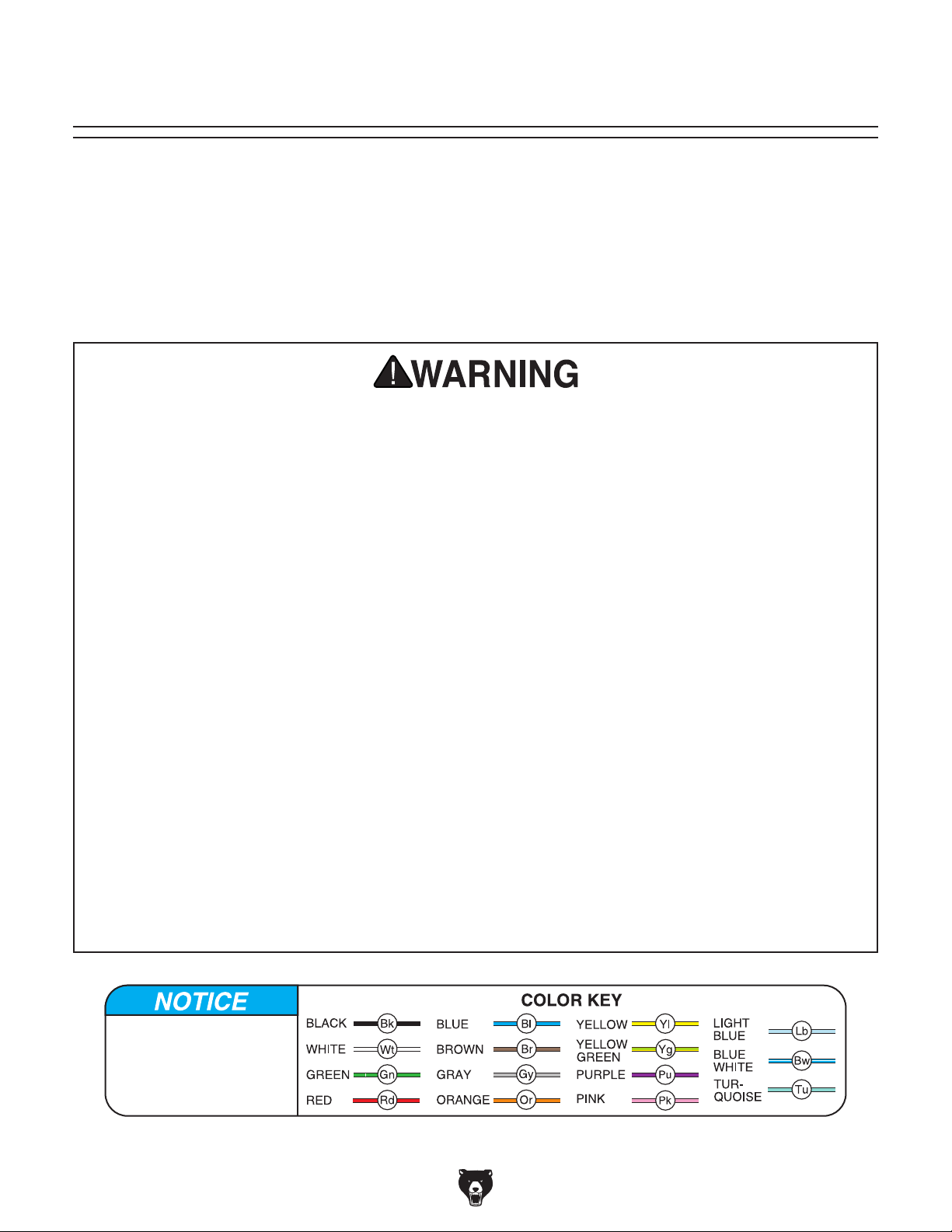
These pages are current at the time of printing. However, in the spirit of improvement, we may make changes to the electrical systems of future machines. Compare the manufacture date of your machine to the one
number and manufacture date of your
machine before calling. This information can be found on the main machine label.
machine
SECTION 8: WIRING
stated in this manual, and study this section carefully.
If there are differences between your machine and what is shown in this section, call Technical Support at
(570) 546-9663 for assistance BEFORE making any changes to the wiring on your machine. An updated
wiring diagram may be available. Note: Please gather the serial
Wiring Safety Instructions
SHOCK HAZARD. Working on wiring that is con-
nected to a power source is extremely dangerous.
Touching electrified parts will result in personal
injury including but not limited to severe burns,
electrocution, or death. Disconnect the power
from the machine before servicing electrical components!
MODIFICATIONS. Modifying the wiring beyond
what is shown in the diagram may lead to unpredictable results, including serious injury or fire.
This includes the installation of unapproved aftermarket parts.
WIRE CONNECTIONS. All connections must
be tight to prevent wires from loosening during
machine operation. Double-check all wires disconnected or connected during any wiring task to
ensure tight connections.
CIRCUIT REQUIREMENTS. You MUST follow
the requirements at the beginning of this manual
when connecting your machine to a power source.
WIRE/COMPONENT DAMAGE. Damaged wires
or components increase the risk of serious personal injury, fire, or machine damage. If you notice
that any wires or components are damaged while
performing a wiring task, replace those wires or
components.
MOTOR WIRING. The motor wiring shown in
these diagrams is current at the time of printing
but may not match your machine. If you find this
to be the case, use the wiring diagram inside the
motor junction box.
CAPACITORS/INVERTERS. Some capacitors
and power inverters store an electrical charge for
up to 10 minutes after being disconnected from
the power source. To reduce the risk of being
shocked, wait at least this long before working on
capacitors.
EXPERIENCING DIFFICULTIES. If you are experiencing difficulties understanding the information
included in this section, contact our Technical
Support at (570) 546-9663.
The photos and diagrams
included in this section are
best viewed in color. You
can view these pages in
color at www.grizzly.com.
-46-
Model G0942/G0943 (Mfd. Since 03/21)

Ground
Ground
MOTOR 230V
WEG ESWS-B38V24E-RM35
G0942 Wiring Diagram
Ground
START
CAPACITOR
270-324uF
250V
T1/U1
START
CAPACITOR
270-324uF
T4/U2
T8/V2
T3/V3
RUN
CAPACITOR
60uF 400V
250V
Ground
230
Hot
VAC
Hot
DISCONNECT
SWITCH
(as recommended
PRESSURE
SUNNY SP-205-25A
)
Ground
LINE
MOTOR
SWITCH
1L1
WEG
CWB38
3L2
A113NO
CONTACTOR
208-240V
A214NO
2T1 4T2
OL RELAY
WEG
RW27-2D
96NC 98NO 97NO 95NC
2T1
4T2
6T3
32
34
36
38
40
Model G0942/G0943 (Mfd. Since 03/21)
MAGNETIC SWITCH
READ ELECTRICAL SAFETY
ON PAGE 46!
-47-

G0942 Electrical Component Photos
Figure 62. Pressure switch wiring.
Figure 63. Motor junction box wiring.
Figure 64. Magnetic switch box wiring.
-48-
READ ELECTRICAL SAFETY
ON PAGE 46!
Model G0942/G0943 (Mfd. Since 03/21)

MOTOR
G0943 230V Wiring Diagram
Prewired 230V
T7/U3
T1/U1
T6/W2
T8/V3
T4/U2
T2/V1
T9/W3
T3/W1
T5/V2
Ground
T2
L2
T1
L1
PRESSURE
SWITCH
SQUARE D 9013 FHG54M1X
3-PHASE
230 VAC
Ground
Hot
Hot
1/L1 3/L2 5/L3
208-240V
CONTACTOR
EATON
A27SNE30 D1
2/T1 4/T2 6/T3
OL RELAY
EATON XTOB DP
40
A
TEST
24
32
95 96 97 98
NC NO
H A
RESET
4T2 6T32T1
Hot
DISCONNECT
SWITCH
(as recommended
Model G0942/G0943 (Mfd. Since 03/21)
)
MAGNETIC SWITCH
EATON A27SGE30B040
READ ELECTRICAL SAFETY
-49-
ON PAGE 46!

MOTOR
G0943 460V Wiring Diagram
Rewired 460V
T6/W2
T9/W3
Ground
T2
L2
T1
L1
PRESSURE
SWITCH
SQUARE D 9013 FHG54M1X
T1/U1
T7/U3
T4/U2
T5/V2
T8/V3
T2/V1
T3/W1
1/L1 3/L2 5/L3
460V
CONTACTOR
EATON
C25DNC325 E1
2/T1 4/T2 6/T3
-50-
3-PHASE
460 VAC
Ground
Hot
Hot
Hot
DISCONNECT
SWITCH
(as recommended
READ ELECTRICAL SAFETY
ON PAGE 46!
OL RELAY
EATON XTOB0320CC1 DP
32
TEST
A
28
24
95 96 97 98
NC NO
)
MAGNETIC SWITCH
H A
RESET
4T2 6T32T1
Model G0942/G0943 (Mfd. Since 03/21)

G0943 Electrical Component Photos
Figure 65. Pressure switch wiring.
Figure 66. Motor junction box wiring (230V).
Figure 67. Magnetic switch box wiring (230V).
Model G0942/G0943 (Mfd. Since 03/21)
READ ELECTRICAL SAFETY
ON PAGE 46!
-51-

56
SECTION 9: PARTS
To order parts, contact MEGA by phone at (832) 415-6995 or email at CS@megacompressor.com.
G0942 Pump
31
60
45
46
61
45
43
38
40
29
37
62
40
42
39
2
32
31
25
41
20
45
13
19
11
63
36
35
18
41
12
14
21
44
17
23
6
16
15
24
15
29
32
11
34
31
51
33
16
45
50
10
14
11
50
53
16
49
57
28
8
7
29
9
3
17
35
55
54
47
-52-
51
50
48
5
52
26
51
27
59
58
4
30
1
31
64
32
12
33
34
36
44
29
Model G0942/G0943 (Mfd. Since 03/21)

REF DE S CRIPTION QTY REF DE S CRIPTION QTY
G0942 Pump Parts List
1 CRANKCASE 1 34 VALVE PLATE ASSEMBLY (STAGE 1) 2
2 BALL BEARING 6304-OPEN 1 35 CYLINDER HEAD GASKET (STAGE 1) 2
3 BALL BEARING 6307-OPEN 1 36 CYLINDER HEAD (STAGE 1) 2
4 BEARING COVER GASKET 1 37 VALVE PLATE GASKET (UPPER) 1
5 CRANKSHAFT BEARING COVER 4MM 1 38 CYLINDER HEAD GASKET (STAGE 1) 1
6 BEARING SEAT GASKET 1 39 VALVE PLATE GASKET (LOWER) 1
7 CRANKSHAFT BEARING SEAT 1 40 VALVE PLATE 2
8 OIL SEAL 35 X 56 X 12 1 41 REED VALVE 2
9 PLATE 79.5 X 36 1 42 CYLINDER HEAD (STAGE 2) 1
10 CRANKSHAFT 1 43 HEX BOLT M8-1.25 X 55 4
11 CYLINDER GASKET (LOWER) 3 44 HEX BOLT M8-1.25 X 75 8
12 CYLINDER (STAGE 1) 2 45 ELBOW FITTING 90-DEG R 3/4" G 3/4" 4
13 CYLINDER (STAGE 2) 1 46 INTERCOOLER 1
14 PISTON (STAGE 1) 2 47 TEE FITTING 180-DEG R 3/4" 2 X G 3/4" 1
15 PISTON PIN (STAGE 1) 2 48 EXHAUST COPPER PIPE (LONG) 1
16 INT RETAI NING RI NG 15MM 6 49 EXHAUST COPPER PIPE (SHORT) 1
17 PISTON RING SET (STAGE 1) 3 PC 2 50 COPPER PIPE LINING 4
18 PISTON (STAGE 2) 1 51 EXHAUST NUT M27 4
19 PISTON PIN )STAGE 2) 1 52 COPPER PIPE FIN (LONG) 1
20 PISTON RING SET (STAGE 2) 3 PC 1 53 COPPER PIPE FIN (SHORT) 1
21 CONNECTI NG ROD (L EFT) 1 54 PUMP FLYWHEEL 1
23 CONNECTI NG ROD (RI GHT) 1 55 FLAT WASHER 10 X 52 X 5MM 1
24 CONNECTI NG ROD (CE NTER) 1 56 HEX BOLT M10-1.5 X 40 LH 1
25 EXT RETAI NING RI NG 30MM 1 57 FLAT WASHER 10MM 1
26 HEX BOLT M6-1 X 16 3 58 OIL DRAIN PLUG Z 3/8" 1
27 LOCK WASHER 6MM 3 59 OIL SIGHT GLASS G 3/4" ALUMINUM 1
28 HEX BOLT M8-1.25 X 25 6 60 ELBOW FITTING 90-DEG R 1/4" 1
29 LOCK WASHER 8MM 18 61 SAFETY RELIEF VALVE R 1/4" 1
30 STUD-SE M10-1.5 X 20, 15 12 62 AIR FILTER ASSEMBLY 2
31 LOCK WASHER 10MM 13 63 OIL FILL PLUG 1
32 HEX NUT M10-1. 5 12 64 FILTER ELEMENT 1
33 CYLINDER GASKET (UPPER) (STAGE 1) 2
Model G0942/G0943 (Mfd. Since 03/21)
-53-

84
7
G0943 Pump
82
83
38
74
35
36
34
33
40
74
29
25
65
48
47
46
41
64
50
42
63
31
26
44
20
3
4
62
23
31
28
25
66
22
61
38
35
30
27
29
21
24
33
6
11
36
55
54
53
34
12
77
51
52
55
13
8
5
10
7
78
88
86
73
75
76
14
15
9
71
81
85
8
18
17
16
14A
19
9A
7A
60
2
1
-54-
Model G0942/G0943 (Mfd. Since 03/21)

REF DES CRIPTION QTY RE F DESCRIP TI ON QTY
G0943 Pump Parts List
1 CRANK CASE 1 36 HEX BOLT M8-1.25 X 30 3
2 OIL DRAIN PLUG 1 38 HEX BOLT M10-1.5 X 45 18
3 OIL SI GHT GLASS 1 40 CYLINDER (STAGE 2) 1
4 OIL FILL PLUG 1 41 CONNECTI NG ROD (S TAGE 2) 1
5 CRANK SHAFT 1 42 NEEDLE ROLLER BEARING NK 20/20 1
6 BALL BEARING 6308-OPEN 1 44 PI STON (STAGE 2) 1
7 BEARING SEAT GASKET 1 46 PISTON PIN (STAGE 2) 1
7A BEARING COVER GASKET 1 47 COMPRESSOR OIL RING (STAGE 2) 1
8 BALL BEARING 6309-OPEN 1 48 PI STON RING SET (STAGE 2) 3 PC 3
9 CRANKSHAFT BEARING SEAT 1 50 VALVE SEAT ASSEMBLY (STAGE 2) 3
9A CRANKSHAFT BEARING COVER 1 51 VALVE SEAT ASSEMBLY (STAGE 1) 3
10 OIL SEAL 1 52 I NLET VALVE PLATE 3
11 FLAT WASHER 51 X 70 X 1.5MM 1 53 OUTLET VALVE PLATE (LOWER) 15
12 EXT RE TAI NI NG RI NG 50MM 1 54 OUTLET VALVE PLATE (UPPER) 15
13 WOODRUFF KEY 8 X 32MM 1 55 HEX BOLT M3-.5 X 13 36
14 HEX BOLT M10-1.5 X 25 6 60 AIR FILTER ASSEMBLY 2
14A HEX BOLT M8-1.25 X 25 4 61 FI L TER MOUNT 2
15 COMPRESSOR PULLEY 1 62 FILTER BASE 2
16 FLAT WASHER 12.5 X 75 X 7MM 1 63 FI LTER 2
17 LOCK WASHER 12M 1 64 FILTER COVER 2
18 HEX BOLT M12-1.75 X 45 1 65 WI NG NUT M6-1 2
19 BREA THER CAP 1 66 FILTER GASKET 2
20 ROD I NNER RI NG 3 71 ELBOW FITTING 90-DEG 1
21 CONNECTI NG ROD (S TAGE 1) 2 73 TE E FI TTI NG 1
22 OIL SPLASH PLATE 2 74 ELBOW FITTING 90-DEG 2
23 HEX BOLT M6-1 X 12 2 75 FIN PIPE ASSEMBLY (STAGE 1) 1
24 PISTON (FIRST STAGE) 2 76 STRAIGHT PIPE CONNECTOR PT 7/8"-14 2
25 I NT RE TAI NI NG RI NG 20MM 6 77 FIN PIPE ASSEMBLY (STAGE 2) 1
26 PISTON PIN (FIRST STAGE) 2 78 STRAIGHT PIPE CONNECTOR PT 1"-11 2
27 COMPRESSOR OIL RING (STAGE 1) 2 81 ELBOW FITTING 90-DEG 1
28 PISTON RING SET (STAGE 1) 3 PC 6 82 TEE FI TTING 2
29 CYLINDER GASKET (LOWER) 3 83 DISCHARGE PIPE 2
30 CYLINDER (STAGE 1) 2 84 STRAIGHT PIPE CONNECTOR PT 1/4"-19 5
31 HEX BOLT M10-1.5 X 30 12 85 UNLOADER VALVE 3
33 CYLINDER GASKET (UPPER) 3 86 UNLOADER VALVE SPRING 3
34 CYLINDER HEAD GASKET 3 87 OI L RI NG 3
35 CYLI NDER HEAD 3 88 STRAI GHT FI TTI NG 3
Model G0942/G0943 (Mfd. Since 03/21)
-55-

G0942 Tank & Motor
104
120
111
145
112
107
113
138
140
108
137
117
114
115
137
137
138
138
143
105
144
139
102
130
140
141
123
128
133
122
134
119
126
103
129
131
132
125
135
-56-
121
124
136
Model G0942/G0943 (Mfd. Since 03/21)
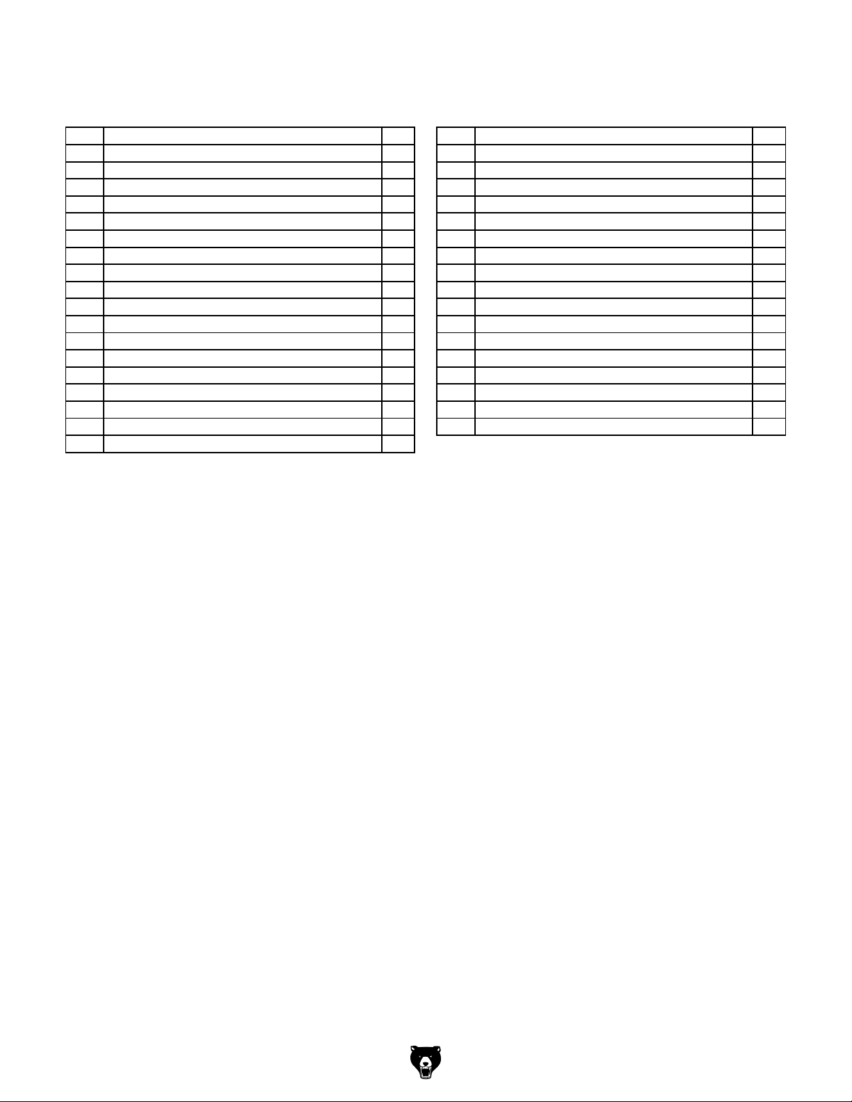
REF DESCRIP TION QTY REF DESCRIPTION QTY
G0942 Tank & Motor Parts List
102 TANK 1 126 V-BELT B74 1
103 MOTOR 7.5HP 230V 1-PH 1 128 BELT GUARD 1
104 PRESSURE SWITCH SUNNY SP-204 1 129 BELT GUARD MOUNTI NG BRACK ET 1
105 SAFETY RELIEF VALVE 1 130 REDUCING ADAPTER 3/4" X 1/4" 1
107 PIPE NIPPLE 1 131 FLA T WASHER 8MM 4
108 PRESSURE GAUGE 1 132 HEX BOLT M8-1.25 X 16 4
111 PUMP DI SCHARGE LI NE 1 133 HEX NUT M1 0-1 . 5 4
112 ELBOW FITTING 90-DEG 1 134 LOCK WASHER 10MM 4
113 THREADED CHECK VALVE 1 135 FLAT WASHER 10.5 X 38.3 X 1.2MM 8
114 DISCHARGE FITTI NG 1 136 HEX BOLT M10-1.5 X 38 4
115 DISCHARGE PIPE 1 137 HEX NUT M8 -1.25 4
117 MAG SWITCH EATON 1 138 LOCK WASHER 8MM 4
119 STRAIN RELIEF TYPE-1 3/4" 1 139 BEL T GUARD MOUNTI NG BRACKET 1
120 CHECK VALVE 3/4" 1 140 FENDER WAS HER 8MM 4
121 BALL DRAIN VALVE 1 141 HEX BOLT M8-1.25 X 12 1
122 OUTLET VALVE 1 143 FLAT WASHER 8.2 X 38 X 1MM 1
123 MAG SWITCH CORD 12G 3W 10" 1 144 HEX BOLT M8-1.25 X 8 1
124 MOTOR CORD 8G 3W 10" 1 145 HEX BOLT M8-1.25 X 30 2
125 MOTOR PULLEY ASSEMBLY 1
Model G0942/G0943 (Mfd. Since 03/21)
-57-
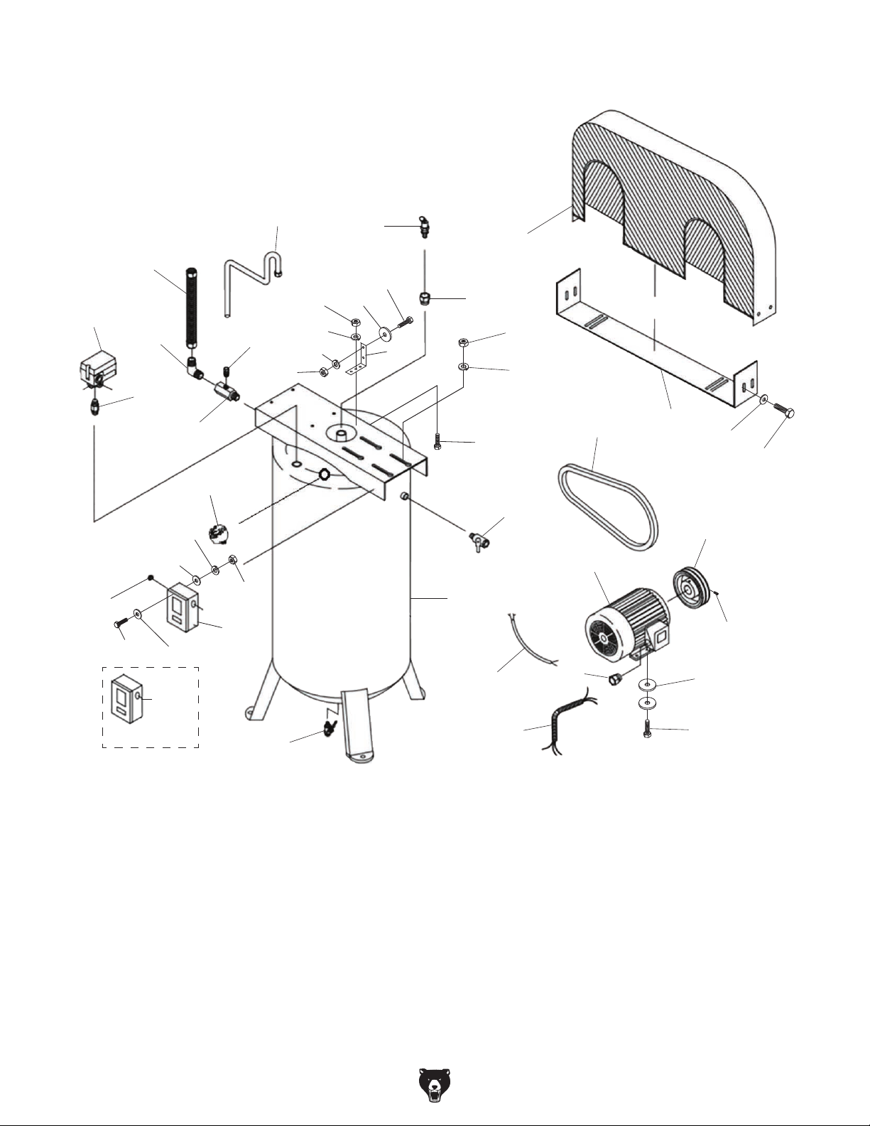
G0943 Tank & Motor
104
120
111
145
112
107
140
140
118
113
138
108
137
117
114
115
137
137
138
138
143
105
144
139
102
130
141
123
128
133
122
134
119
126
103
129
131
132
125
142
135
-58-
(460V Only)
121
124
136
Model G0942/G0943 (Mfd. Since 03/21)

REF DESCRIP TION QTY REF DESCRIPTION QTY
G0943 Tank & Motor Parts List
102 TA NK 1 126 V-BELT B90 1
103 MOTOR 10HP 230V/460V 3-PH 1 128 BELT GUARD 1
104 PRESSURE SWITCH SQUARE D4 PORT 1 129 B ELT G UARD MOUNTI NG BRACKET 1
105 SAFETY RELIEF VALVE 1 130 REDUCING ADAPTER 3/4" X 1/4" 1
107 PI PE NIPPLE 1 131 FLAT WASHER 8MM 4
108 PRESSURE GAUGE 1 132 HEX BOLT M8-1.25 X 16 4
111 P UMP DI SCHARGE LI NE 1 133 HEX NUT M1 0-1. 5 4
112 ELBOW FITTING 90-DEG 1 134 LOCK WASHER 10MM 4
113 THREADED CHECK VALVE 1 135 FLAT WASHER 10.5 X 38.3 X 1.2MM 8
114 DI SCHARGE FI TTING 1 136 HEX BOLT M10-1.5 X 38 4
115 DISCHARGE PIPE 1 137 HEX NUT M8-1.25 4
117 MAG SWITCH EATON 230V 1 138 LOCK WASHER 8MM 4
118 MAG SWITCH EATON 460V 1 139 B ELT GUARD MOUNTI NG BRA CKET 1
119 CO NNECTOR 3/ 4" 1 140 FENDE R WASHER 8MM 4
120 CO NNECTOR 3/ 8" 1 141 HEX BOLT M8-1.25 X 12 1
121 BALL DRAIN VALVE 1 142 SET SCREW 5/16-18 X 6 2
122 OUTLET VALVE 1 143 FLAT WASHER 8.2 X 38 X 1MM 1
123 MAG SWITCH CORD 12G 3W 12" 1 144 HEX BOLT M8-1.25 X 8 1
124 MOTOR CORD 8G 4W 12" 1 145 HEX BOLT M8-1.25 X 30 2
125 MOTOR PULLEY ASSEMBLY 1
Model G0942/G0943 (Mfd. Since 03/21)
-59-

G0942 Labels & Cosmetics
REF PART # DES CRIPTIO N REF PART # DES CRIPTI ON
209
208
A
SSEMBLED IN
WITH US & GLOBAL PARTS
207
WARNING!
DRAIN TANK
AFTER
EVERY USE!
206
205
Specifications
Motor: 7.5 HP, 230V, 1-Ph, 60 Hz
Full-Load Current Rating: 31A
Pump Type: Two-Stage
Max. Airflow @ 90 PSI: 23 CFM
Cut-Out Pressure: 175 PSI
Cut-In Pressure: 145 PSI
Duty Cycle: 60/40
Tank Size: 80 Gallons
Connection Size: 3/4" NPT
Weight: 565 lbs.
Mfd. for Grizzly in USA
80-GALLON 7.5 HP EXTREME-SERIES AIR COMPRESSOR
To reduce the risk of serious injury when using this machine:
1. Read and understand owner’s manual before operating.
2. Always wear ANSI-approved eye protection and any additional
personal protective equipment required by attachment tools.
3. Properly ground machine—connect to permanently grounded
metal wiring system or an equipment grounding conductor.
4. DO NOT use this air compressor for breathable air supply.
5. DO NOT touch compressor parts during or immediately
following operation. These parts will be hot.
6. Disconnect power and drain tank before moving or servicing.
DO NOT pull compressor by power conduit or air hose.
7. DO NOT adjust or remove safety valve or modify machine.
S/N
8. Only operate in well-ventilated area free of combustible
materials. DO NOT smoke while spraying, and do not spray
flammable material in confined area near flame/compressor.
Date
Locate compressor at least 20 feet from spray area.
9. Only operate with all guards, covers, and parts in place.
10. Never leave machine running unattended.
MODEL G0942
WARNING!
11. Avoid entanglement with moving parts—tie back long hair, roll
up sleeves, and do not wear loose clothing, gloves, or jewelry.
12. DO NOT use if power supply wires, conduit, or any other
electrical equipment becomes damaged—promptly repair!
13. DO NOT stand on compressor or obstruct airflow to ventilation.
14. DO NOT exceed pressure rating of tools or attachments.
15. DO NOT aim compressed air at body parts or people.
16. Inspect compressor, air lines, valves, and tank for damage,
leaks, weakness, looseness, or excessive wear. Repair/replace
defective items before operating.
17. Drain moisture from tank after each use and promptly replace a
damaged tank. DO NOT attempt to weld on, modify, or repair
tank.
18. DO NOT expose to rain or use in wet locations.
19. DO NOT operate under influence of drugs or alcohol or when
tired.
20. Prevent unauthorized use by children or untrained users.
G0942
204
201
202
grizzly.com
203
201 P0942201 ELECTRICITY LABEL 206 P0942206 EXTREME SERIES LABEL
202 P0942202 TOUCH-UP PAI NT, G RI ZZLY GREEN 207 P0942207 DRAIN TANK LABEL
203 P0942203 GRIZZLY.COM LABEL 208 P0942208 ASSEMBLED IN USA LABEL
204 P0942204 MODEL NUMBER LABEL 209 P0942209 TOUCH-UP P AI NT, GRI ZZLY BL ACK
205 P0942205 MACHINE ID LABEL
-60-
Model G0942/G0943 (Mfd. Since 03/21)

G0943 Labels & Cosmetics
209
Specifications
Motor: 10 HP, 230V or 460V, 3-Ph, 60 Hz
Prewired Voltage: 230V
Full-Load Current: 24A @ 230V, 12A @ 460V
Pump Type: Two-Stage
Max. Airflow @ 90 PSI: 40 CFM
Cut-Out Pressure: 175 PSI
Cut-In Pressure: 145 PSI
Duty Cycle: 70/30
Tank Size: 120 Gallons
Connection Size: 3/4" NPT
Weight: 950 lbs.
S/N
Date
Mfd. for Grizzly in USA
120-GALLON 10 HP EXTREME-SERIES AIR COMPRESSOR
To reduce the risk of serious injury when using this machine:
1. Read and understand owner’s manual before operating.
2. Always wear ANSI-approved eye protection and any additional
personal protective equipment required by attachment tools.
3. Properly ground machine—connect to permanently grounded
metal wiring system or an equipment grounding conductor.
4. DO NOT use this air compressor for breathable air supply.
5. DO NOT touch compressor parts during or immediately
following operation. These parts will be hot.
6. Disconnect power and drain tank before moving or servicing.
DO NOT pull compressor by power conduit or air hose.
7. DO NOT adjust or remove safety valve or modify machine.
8. Only operate in well-ventilated area free of combustible
materials. DO NOT smoke while spraying, and do not spray
flammable material in confined area near flame/compressor.
Locate compressor at least 20 feet from spray area.
9. Only operate with all guards, covers, and parts in place.
10. Never leave machine running unattended.
MODEL G0943
WARNING!
11. Avoid entanglement with moving parts—tie back long hair, roll
up sleeves, and do not wear loose clothing, gloves, or jewelry.
12. DO NOT use if power supply wires, conduit, or any other
electrical equipment becomes damaged—promptly repair!
13. DO NOT stand on compressor or obstruct airflow to ventilation.
14. DO NOT exceed pressure rating of tools or attachments.
15. DO NOT aim compressed air at body parts or people.
16. Inspect compressor, air lines, valves, and tank for damage,
leaks, weakness, looseness, or excessive wear. Repair/replace
defective items before operating.
17. Drain moisture from tank after each use and promptly replace a
damaged tank. DO NOT attempt to weld on, modify, or repair
tank.
18. DO NOT expose to rain or use in wet locations.
19. DO NOT operate under influence of drugs or alcohol or when
tired.
20. Prevent unauthorized use by children or untrained users.
201
208
A
SSEMBLED IN
WITH US & GLOBAL PARTS
207
206
G0943
205
grizzly.com
202
203
WARNING!
DRAIN TANK
AFTER
EVERY USE!
204
REF PART # DES CRIPTIO N REF PART # DES CRIPTI ON
201 P0943201 TOUCH-UP PAI NT, G RI ZZLY BLACK 206 P0943206 MODEL NUMBER LABEL
202 P0943202 ELECTRICITY LABEL 207 P0943207 EXTREME SERIES LABEL
203 P0943203 DRAIN TANK LABEL 208 P0943208 ASSEMBLED IN USA LABEL
204 P0943204 TOUCH-UP PAI NT, G RI ZZLY GREEN 209 P0943209 MACHINE ID LABEL
205 P0943205 GRIZZLY.COM LABEL
Safety labels help reduce the risk of serious injury caused by machine hazards. If any label comes
off or becomes unreadable, the owner of this machine MUST replace it in the original location
before resuming operations. For replacements, contact (800) 523-4777 or www.grizzly.com.
Model G0942/G0943 (Mfd. Since 03/21)
-61-

 Loading...