

Page 1

MODEL G0932
4' X 8' CNC ROUTER
w/VACUUM TABLE
OWNER'S MANUAL
(For models manufactured since 02/21)
COPYRIGHT © DECEMBER, 2022 BY GRIZZLY INDUSTRIAL, INC.
WARNING: NO PORTION OF THIS MANUAL MAY BE REPRODUCED IN ANY SHAPE
OR FORM WITHOUT THE WRITTEN APPROVAL OF GRIZZLY INDUSTRIAL, INC.
#KS22128 PRINTED IN CHINA
***Keep for Future Reference***
V1.1 2.22
Page 2

This manual provides critical safety instructions on the proper setup,
operation, maintenance, and service of this machine/tool. Save this
document, refer to it often, and use it to instruct other operators.
Failure to read, understand and follow the instructions in this manual
may result in fire or serious personal injury—including amputation,
electrocution, or death.
The owner of this machine/tool is solely responsible for its safe use.
This responsibility includes but is not limited to proper installation in
a safe environment, personnel training and usage authorization,
proper inspection and maintenance, manual availability and comprehension, application of safety devices, cutting/sanding/grinding tool
integrity, and the usage of personal protective equipment.
The manufacturer will not be held liable for injury or property damage
from negligence, improper training, machine modifications or misuse.
Some dust created by power sanding, sawing, grinding, drilling, and
other construction activities contains chemicals known to the State
of California to cause cancer, birth defects or other reproductive
harm. Some examples of these chemicals are:
• Lead from lead-based paints.
• Crystalline silica from bricks, cement and other masonry products.
• Arsenic and chromium from chemically-treated lumber.
Your risk from these exposures varies, depending on how often you
do this type of work. To reduce your exposure to these chemicals:
Work in a well ventilated area, and work with approved safety equipment, such as those dust masks that are specially designed to filter
out microscopic particles.
Page 3

Table of Contents
INTRODUCTION ............................................... 2
Contact Info.................................................... 2
Manual Accuracy
Identification
Controls & Components
Controller Functions
Glossary Of Terms
Machine Data Sheet
SECTION 1: SAFETY
Safety Instructions for Machinery
Additional Safety for 4-Axis CNC Routers
SECTION 2: POWER SUPPLY
SECTION 3: SETUP
Needed for Setup
Unpacking
Inventory
Site Considerations
Lifting & Placing CNC Router
Assembly
Leveling
Connecting Controller
Lifting & Mounting Vacuum Pump
Anchoring Vacuum Pump to Floor
Connecting Vacuum Pump & Filter
Dust Collection
Power Connections
Test Run
Verifying Parameters
SECTION 4: OPERATIONS
Operation Overview
Workpiece Inspection................................... 35
Choosing Cutter
Changing Cutter
Securing Workpiece on Table...................... 37
Using a Spoilboard
.................................................... 16
...................................................... 17
..................................................... 21
........................................................ 23
...................................................... 30
........................................... 2
................................................... 3
................................. 4
....................................... 6
......................................... 7
...................................... 9
..................................... 11
................ 11
... 13
...................... 14
....................................... 16
......................................... 16
...................................... 19
...................... 20
.................................. 23
............... 24
............... 24
............. 25
............................................. 26
...................................... 27
................................... 32
........................... 34
..................................... 34
........................................... 35
........................................... 36
...................................... 39
Using Rotary C-Axis
Adjusting Axis Positions Manually
Homing Axes................................................ 44
Setting Work Origin
Creating G-Code File
Uploading & Running G-Code
Manually Setting Spindle Speed
Changing Advanced Settings
Using Advanced Controls
SECTION 5: ACCESSORIES
SECTION 6: MAINTENANCE
Schedule
Cleaning & Protecting
Lubrication
SECTION 7: SERVICE
Troubleshooting
Testing Proximity Switches
Updating RichAuto Controller Software
Configuring Stepper Drivers
SECTION 8: WIRING
Wiring Safety Instructions
Spindle Motor Wiring Diagram
Power Components Wiring Diagram
Stepper Motors Wiring Diagram
Interface Board Wiring Diagram
Contactor Wiring Diagram
Electrical Components
SECTION 9: PARTS
Frame & Bed
Gantry & Spindle
Electrical & Accessories
Labels & Cosmetics
WARRANTY & RETURNS
...................................................... 53
................................................... 53
................................................ 70
.................................... 41
............... 43
...................................... 44
................................... 46
..................... 47
.................. 48
...................... 49
............................ 49
......................... 50
......................... 53
.................................. 53
................................... 56
........................................... 56
.......................... 60
....... 61
........................ 62
...................................... 63
............................ 63
..................... 64
........... 64
.................. 65
.................. 66
........................... 66
................................. 67
....................................... 70
.......................................... 72
.............................. 74
..................................... 76
............................. 77
Page 4

We stand behind our machines! If you have questions or need help, contact us with the information
below. Before contacting, make sure you get the
serial number
machine ID label. This will help us help you faster.
We want your feedback on this manual. What did
you like about it? Where could it be improved?
Please take a few minutes to give us feedback.
Email: manuals@grizzly.com
We are proud to provide a high-quality owner’s
manual with your new machine!
We
instructions, specifications, drawings, and photographs
in this manual. Sometimes we make mistakes, but
our policy of continuous improvement also means
that
you receive is
slightly different than shown in the manual
If you find this to be the case, and the difference
between the manual and machine leaves you
confused or unsure about something
check our
website for an updated version. W
current
manuals and
on our web-
site at
Alternatively, you can call our Technical Support
for help. Before calling, make sure you write
down the
serial number
from the machine ID label (see below). This
information is required for us to provide proper
tech support, and it helps us determine if updated
documentation is available for your machine.
INTRODUCTION
Contact Info
and manufacture date from the
Grizzly Technical Support
1815 W. Battlefield
Springfield, MO 65807
Phone: (570) 546-9663
Email: techsupport@grizzly.com
Grizzly Documentation Manager
P.O. Box 2069
Bellingham, WA 98227-2069
Manual Accuracy
made every effort to be exact with the
sometimes the machine
.
,
e post
manual updates for free
www.grizzly.com.
manufacture date and
Manufacture Date
Serial Number
-2-
Model G0932 (Mfd. Since 02/21)
Page 5

To reduce your risk of
serious injury, read this
entire manual BEFORE
Identification
Become familiar with the names and locations of the controls and features shown below to better understand
the instructions in this manual.
Spindle Motor
(Behind Dust Shield)
Vacuum
Table
Controller
Electrical
Cabinet
ON Button Cooling Fan
EMERGENCY
STOP Button
3-Jaw Chuck
Z-Axis Stepper Motor
Vacuum Valves
Tailstock
(Behind Cover)
Dust Shield
Gantry
Y-Axis Stepper
Motor (Behind Cover)
Z-Axis Proximity Switch
(Behind Cover)
X-Axis Stepper Motor
(Behind Cover)
X-Axis Proximity
Switch
Oiler
System
C-Axis
Proximity
Z-Axis
Y-Axis
X-Axis
C-Axis
Model G0932 (Mfd. Since 02/21)
Switch
C-Axis
Stepper
Motor
Vacuum Hose
Y-Axis Proximity Switch
(Behind Cover)
using machine.
Y-Axis Stepper
Motor (Behind Cover)
-3-
Page 6

To reduce your risk of
serious injury, read this
entire manual BEFORE
Controls &
Components
Spindle Assembly
using machine.
Refer to the following figures and descriptions to
become familiar with the basic controls and components of this machine. Understanding these
items and how they work will help you understand
the rest of the manual and minimize your risk of
injury when operating this machine.
Power Controls
A
B
D
F
Figure 2. Spindle components.
D. Spindle Motor: A 4 HP motor capable of
turning the cutting tool at 0–18,000 RPM.
E. Spindle: Motor shaft that holds the cutting
tool, spindle nut, and collet.
F. ER25 Collet: Holds cutting tool.
G. Spindle Nut: Secures collet and cutting tool
on spindle.
E
G
Vacuum Table Components
C
Figure 1. Power controls on electrical cabinet.
A. RichAuto B18 Controller: Controls machine
functions.
B. ON Button: Enables power to machine.
C. EMERGENCY STOP Button: Disables
power to machine when in depressed position. To reset, twist button clockwise until it
pops out.
H
I
Figure 3. Vacuum pump.
H. Vacuum Pump Motor: Creates suction to
hold workpiece to table.
Vacuum Pump Filter: Cleans air as it is
I.
pulled through vacuum pump motor.
-4-
Model G0932 (Mfd. Since 02/21)
Page 7

K
J
Figure 4. Vacuum valves at side of machine.
O
P
J. Vacuum Valve (1 of 5): Each valve enables/
disables vacuum to one vacuum zone.
Drawings below each valve indicate zone.
K. Vacuum Pressure Gauge: Displays vacuum
pressure in MPa/PSI.
L
M
Figure 5. Vacuum port and plug.
L. Vacuum Plug: Keeps debris out of unused
ports. Remove plug when using port in that
vacuum zone.
M. Vacuum Port: Holds workpiece to table to
prevent movement during operation.
Additional Components
Figure 7. Oiler system components.
O. Oiler System Control Panel: Controls
amount of lubricating oil on linear guide rails
and ball screws.
P. Oil Reservoir: Holds one quart of T27914
ISO 68 machine oil.
Q
Figure 8. C-axis components.
Q. Tailstock: Repositions along the length of the
guide rails to support workpieces. Handwheel
moves live center toward or away from the
chuck before being locked in position.
R
N
Figure 6. Z-axis tool setter.
N. Z-Axis Tool Setter: Establishes Z-axis origin
based on surface tool setter is placed on.
Model G0932 (Mfd. Since 02/21)
R. 3-Jaw Chuck: Uses inside or outside hard-
ened steel jaw sets to center and secure a
concentric workpiece.
-5-
Page 8

Controller Functions
Y+ or 2: Moves gantry along Y-axis in positive
direction. Increases feed rate during process.
Scrolls sub-menu up. Input for "2".
The following commands are used for navigation
of the machine and controller. Additional functions
can be accessed with multi-button commands
(see Using Advanced Controls on Page 49).
Note: Button descriptions are referenced from left
to right, and from top to bottom.
Figure 9. Controller buttons.
BREAK WORK: Resumes work at last known
system position in the event of power failure, job
termination, or broken tooling.
TOOL SET: Activates Z-axis tool setter function.
Z+ or 3: Moves spindle along Z-axis in positive
direction. Increases spindle speed during process. Input for "3".
C+ or 4: Moves rotary spindle along C-axis in
positive direction. Input for "4".
X- or 5: Moves spindle along X-axis in negative
direction. Scrolls menu down. Input for "5".
Y- or 6: Moves gantry along Y-axis in negative
direction. Decreases feed rate during process.
Scrolls sub-menu down. Input for "6".
Z- or 7: Moves spindle along Z-axis in negative
direction. Decreases spindle speed during process. Input for "7".
C- or 8: Moves rotary spindle along C-axis in
negative direction. Input for "8".
ZRN or 9: Returns all axes to home position (see
Page 44). Input for "9".
FAST/ SLOW or 0: In manual mode, selects high
or low speed for axis movement. In auto mode,
switches operational coordinates. Input for "0".
SPINDLE or (.): Turns spindle ON or OFF. Input
for decimal point.
ADVANCED FUNCTION: Accesses Advanced
Functions menu (see Page 49).
REPEAT MACHINING: Repeats last machine
operation.
XY-> 0 : Sets work origin of X- and Y-axes (see
Page 44).
ZC->0: Sets work origin of Z- and C-axes (see
Page 44).
F1: User-defined function key.
F2: User-defined function key.
X+ or 1: Moves spindle along X-axis in positive
direction (see Page 7). Scrolls menu up. Input for
numeral "1".
-6-
MENU or (-): Enters setup menus. Input for the
negative symbol.
REF or OK: Returns all axes to work origin (see
Page 44). Confirms motions, inputs, or opera-
tions.
MODE: Toggles between three jogging modes:
Continuous, Step, or Distance.
RU N /PAUSE or DELETE: Runs or pauses processing. Used to load a program from either the
USB drive or internal memory.
STOP or CANCEL: Stops a running program.
Cancels commands.
Model G0932 (Mfd. Since 02/21)
Page 9

Glossary Of Terms
The following is a list of common definitions, terms and phrases used throughout this manual as they relate
to this CNC router and woodworking in general. Become familiar with these terms for assembling, adjusting
or operating this machine. Your safety is VERY important to us at Grizzly!
Axis: Direction of movement. On a four-axis
machine, axes are typically X (left-right), Y
(front-back), Z (up-down), and C (rotational).
Axis directions are described as positive or
negative. On this machine, positive movement is defined as movement towards the
rear (Y), right (X), top (Z), and clockwise (C)
direction of the working envelope.
Ball End (Ball Nose): A cutting tool that has a
rounded cutting arc, where the arc diameter
is equal to the cutting diameter.
Ball Screw: Drive system component. The ball
screw is rotated by the stepper motor and
provides the means for moving the gantry
and spindle along the axes.
Bed: The bed of the CNC consists of a welded
steel frame, an extruded aluminum table top,
and a tongue-and-groove table top with integrated T-slots.
CAD: Computer aided design. CAD software is
used to create a digital model of a project.
CAM: Computer aided manufacturing. CAM soft-
ware converts CAD models into a toolpath
defined by G-code that CNC machines can
interpret.
Collet: Metal collar that holds the cutting tool in
place within a spindle nut.
Conventional Cut: Cut that occurs when the
rotation of the cutter moves in opposite direction as the workpiece.
Compression Bit: A cutting tool with a combi-
nation of up and down shear cutting edges.
Typically used for cutting laminate material to
prevent tear-out on both sides of the sheet.
Down-Cut Bit: A cutting tool with edges that
carve downward on the face of the toolpath. Reduces the potential for tear-out, but
requires a slower feed rate.
Dust Shoe: An accessory that channels dust and
debris directly from the cutting tool through
an attached dust collection system.
Dwell: Part of an operation in which axis move-
ment stops while the spindle is running and
the cutter is within the workpiece. Dwells
should be avoided as they can lead to tool
and workpiece damage.
End Mill: A cutting tool with a straight end, typi-
cally with spiral flute(s). It creates a channel
with a flat bottom perpendicular to the sides.
Chip Load: Chip load is the measure of the thick-
ness of chips a tool will cut. Chip load is equal
to: Feed Rate ÷ (Spindle Speed X Number of
Flutes).
Climb Cut: Cut that occurs when the rotation of
the cutter moves in same direction as the
workpiece.
CNC: Computer numerical control. Manufacturing
controlled by a computer via coded
instructions.
Model G0932 (Mfd. Since 02/21)
Feed Rate: The speed at which the cutting tool
moves along a workpiece.
Finish Cut: A 3D toolpath that reduces or elimi-
nates the irregular contours left by a rough
cut.
Flutes: The cutting edges or inserts of a router bit
or cutting tool.
Flute Length: The length of the cutting portion on
a router bit or cutting tool.
Form Bit: A bit that carves a standard profile such
as a roundover, ogee, or similar contour.
-7-
Page 10

Gantry: The structure that straddles the bed and
carries the spindle. It moves the full length of
the bed along the Y-axis.
G-Code: A machine language that uses axis
points and commands, which the machine
uses to move and perform functions.
Hold-Down: A clamp used to firmly hold a
workpiece or fixture to the table.
Home Position: A fixed point on the machine set
with proximity switches. It is the machine zero
point on all axes.
Letter Address: The first letter of a G-code
command. Commands with similar functions
are usually grouped within the same letter
address. For example, the "G" letter address
deals with preparatory functions that define
the machine's operation, while the "M" letter address handles miscellaneous machine
functions such as turning on spindles, pumps,
and other auxiliary tasks.
Origin: User designated zero point for a workpiece
from which the router will reference the positioning of all cutting.
Plunge: The distance on the Z-axis that the
spindle and cutting tool moves toward, into,
or along the workpiece.
Pocket Toolpath: A toolpath that creates a cavity
in the horizontal surface of a workpiece.
Post Processor: A software function that formats
G-code into a dialect understood by a specific
machine.
Profile Toolpath: A toolpath that cuts along the
profile of a set of vectors. Typically used to
cut out the shape of a design.
Proximity Switch: A magnetic limit switch that is
used to find home position.
Rapid:
Rough Cut: A 3D toolpath where the initial cut is
The maximum speed of each axis. Higher
rapid rates decrease machining times.
designed to remove unwanted material, leaving a rough contour.
Soft Limits: Axis limits imposed by the work space
boundaries and based on controller settings
and the location of home. An "out of soft limits
error" implies that there is not enough room
to move in a designated direction based on
the positioning of the workpiece.
Spindle Speed: Rotational speed of cutting tool
(RPM).
Spoilboard: Sacrificial material placed under the
workpiece that allows the cutting tool to go
past the workpiece to ensure a full, clean
cut without damaging the work table. Usually
made of MDF.
Stepper Motor: DC motor that moves in precise
steps when pulses are received. Has very
accurate positioning and speed control.
Surfacing: The process of leveling the surface of
a workpiece or spoilboard so it is perpendicular to the spindle.
Toolpath: User defined route that the cutter fol-
lows to machine a workpiece.
Tool Deflection: Tool deflection occurs when the
spindle speed and feed rate exert sufficient
force to deflect the cutting tool. Deflection
leads to excessive wear and chatter, which
can shorten tool life and leave unwanted tooling marks on the material.
Tool Setter: A device used to set the zero point
(origin) for the Z-axis.
Up-Cut Bit: A cutting tool with edges that carve
upward on the face of the toolpath. This
removes chips from the material, but can pull
the material off the bed and splinter the top
edge.
VFD: Variable frequency drive that controls the
speed (RPM) of the spindle. Enables the fine
tuning of the spindle during the operation of
a toolpath.
Working Envelope: The three-dimensional area
that the spindle can travel within while cutting
or milling.
-8-
Model G0932 (Mfd. Since 02/21)
Page 11

Customer Service #: (570) 546-9663 · To Order Call: (800) 523-4777 · Fax #: (800) 438-5901
20A
30A
21A
30A
MODEL G0932
4' X 8' CNC ROUTER WITH VACUUM TABLE
Product Dimensions:
Weight .........................................................................................................................................................................2646 lbs.
Width (side-to-side) x Depth (front-to-back) x Height ...............................................................................93-1/2 x 123 x 63 in.
Footprint (Length x Width) .................................................................................................................................106-1/2 x 76 in.
Shipping Dimensions:
Type ........................................................................................................................................................................ Wood Crate
Content ...................................................................................................................................... Machine and Electrical Cabinet
Weight ..........................................................................................................................................................................3087 lbs.
Length x Width x Height ................................................................................................................................... 128 x 89 x 67 in.
Must Ship Upright .................................................................................................................................................................Yes
Electrical:
Power Requirement ................................................................................................................................ 220V, 3-Phase, 60 Hz
Full-Load Current Rating ......................................................................................................................................................
Minimum Circuit Size ...........................................................................................................................................................
Connection Type .....................................................................................................................Permanent (Hardwire to Shutoff)
Switch Type .............................................................................................................................. ON/OFF Push Button w/E-stop
Inverter (VFD) Type .................................................................................................................................... Delta VFD037E23A
Inverter (VFD) Size .............................................................................................................................................................5 HP
Vacuum Pump Electrical:
Power Requirement ................................................................................................................................ 220V, 3-Phase, 60 Hz
Full-Load Current Rating ......................................................................................................................................................
Minimum Circuit Size ...........................................................................................................................................................
Connection Type .....................................................................................................................Permanent (Hardwire to Shutoff)
Motor:
Spindle Motor
X-Axis Motor
Type
.......................................................................................................................................................................Spindle
Horsepower ...............................................................................................................................................................4 HP
Voltage ..................................................................................................................................................................... 220V
Phase .................................................................................................................................................................. 3-Phase
Amps ....................................................................................................................................................................... 12.5A
Speed ...................................................................................................................................................... 0 - 18,000 RPM
Number Of Speeds ...............................................................................................................................................Variable
Power Transfer ........................................................................................................................................................ Direct
Frame Size
Amps ......................................................................................................................................................................... 4.2A
Speed ......................................................................................................................................................... 0 - 2000 RPM
Type .................................................................................................................. Stepper (Brushless, Permanent Magnet)
Power Transfer ............................................................................................................................................................Belt
Step Resolution .................................................................................................................................... 1.8 deg. Per Step
........................................................................................................................................................ NEMA 34
Model G0932 (Mfd. Since 02/21)
-9-
Page 12

Y-Axis Motor
Z-Axis Motor
Number of Vacuum Zones ..............................................................................................................................................4
Other Specifications:
ID Label
Rotary C-Axis Motor
Main Specifications:
Frame Size ........................................................................................................................................................ NEMA 34
Amps ......................................................................................................................................................................... 4.2A
Speed ......................................................................................................................................................... 0 - 2000 RPM
Type .................................................................................................................. Stepper (Brushless, Permanent Magnet)
Power Transfer ............................................................................................................................................................Belt
Step Resolution .................................................................................................................................... 1.8 deg. Per Step
Frame Size
Amps ......................................................................................................................................................................... 4.2A
Speed ......................................................................................................................................................... 0 - 2000 RPM
Type .................................................................................................................. Stepper (Brushless, Permanent Magnet)
Power Transfer ............................................................................................................................................................Belt
Step Resolution .................................................................................................................................... 1.8 deg. Per Step
Frame Size
Amps ......................................................................................................................................................................... 4.2A
Speed ......................................................................................................................................................... 0 - 2000 RPM
Type .................................................................................................................. Stepper (Brushless, Permanent Magnet)
Power Transfer ...........................................................................................................................Gearbox Reducer (20:1)
Step Resolution .................................................................................................................................... 1.8 deg. Per Step
........................................................................................................................................................ NEMA 34
........................................................................................................................................................ NEMA 34
Axis Information
X-Axis Travel
Y-Axis Travel ....................................................................................................................................................98-7/16 in.
Z-Axis Travel ........................................................................................................................................................7-7/8 in.
Max. Rotary C-Axis Diameter ...............................................................................................................................7-7/8 in.
XY Rapid Speed ................................................................................................................................................ 1181 IPM
Z Rapid Speed .................................................................................................................................................... 400 IPM
Rotary C-Axis Rapid Speed ................................................................................................................................ 472 IPM
Construction
Table .................................................................................................................................................................... Phenolic
Body Construction .....................................................................................................................................................Steel
Paint. .....................................................................................................................................................................Enamel
Cutting Information
XYZ Work Envelope ............................................................................................................ 51-3/16 x 98-7/16 x 7-7/8 in.
Max Distance Spindle to Table ............................................................................................................................7-7/8 in.
Cutting Accuracy .............................................................................................................................................+/-0.002 in.
Table Information
Table Length ............................................................................................................................................................99 in.
Table Width ..............................................................................................................................................................49 in.
....................................................................................................................................................51-3/16 in.
Country of Origin ............................................................................................................................................................... China
Warranty ........................................................................................................................................................................... 1 Year
Approximate Assembly & Setup Time ........................................................................................................................... 4 Hours
Serial Number Location ................................................................................................................................................
-10 -
Model G0932 (Mfd. Since 02/21)
Page 13

SECTION 1: SAFETY
For Your Own Safety, Read Instruction
Manual Before Operating This Machine
The purpose of safety symbols is to attract your attention to possible hazardous conditions.
This manual uses a series of symbols and signal words intended to convey the level of importance of the safety messages. The progression of symbols is described below. Remember that
safety messages by themselves do not eliminate danger and are not a substitute for proper
accident prevention measures. Always use common sense and good judgment.
Indicates an imminently hazardous situation which, if not avoided,
WILL result in death or serious injury.
Indicates a potentially hazardous situation which, if not avoided,
COULD result in death or serious injury.
Indicates a potentially hazardous situation which, if not avoided,
MAY result in minor or moderate injury. It may also be used to alert
against unsafe practices.
Alerts the user to useful information about proper operation of the
NOTICE
machine to avoid machine damage.
Safety Instructions for Machinery
OWNER’S MANUAL. Read and understand this
owner’s manual BEFORE using machine.
TRAINED OPERATORS ONLY. Untrained operators have a higher risk of being hurt or killed.
Only allow trained/supervised people to use this
machine. When machine is not being used, disconnect power, remove switch keys, or lock-out
machine to prevent unauthorized use—especially
around children. Make your workshop kid proof!
DANGEROUS ENVIRONMENTS. Do not use
machinery in areas that are wet, cluttered, or have
poor lighting. Operating machinery in these areas
greatly increases the risk of accidents and injury.
MENTAL ALERTNESS REQUIRED. Full mental
alertness is required for safe operation of machinery. Never operate under the influence of drugs or
alcohol, when tired, or when distracted.
ELECTRICAL EQUIPMENT INJURY RISKS.
You can be shocked, burned, or killed by touching
live electrical components or improperly grounded
machinery. To reduce this risk, only allow qualified
service personnel to do electrical installation or
repair work, and always disconnect power before
accessing or exposing electrical equipment.
DISCONNECT POWER FIRST.
nect machine from power supply BEFORE making adjustments, changing tooling, or servicing
machine. This prevents an injury risk from unintended startup or contact with live electrical components.
EYE PROTECTION. Always wear ANSI-approved
safety glasses or a face shield when operating or
observing machinery to reduce the risk of eye
injury or blindness from flying particles. Everyday
eyeglasses are NOT approved safety glasses.
Always discon-
Model G0932 (Mfd. Since 02/21)
-11-
Page 14

WEARING PROPER APPAREL. Do not wear
clothing, apparel or jewelry that can become
entangled in moving parts. Always tie back or
cover long hair. Wear non-slip footwear to reduce
risk of slipping and losing control or accidentally
contacting cutting tool or moving parts.
HAZARDOUS DUST. Dust created by machinery
operations may cause cancer, birth defects, or
long-term respiratory damage. Be aware of dust
hazards associated with each workpiece material. Always wear a NIOSH-approved respirator to
reduce your risk.
HEARING PROTECTION. Always wear hearing protection when operating or observing loud
machinery. Extended exposure to this noise
without hearing protection can cause permanent
hearing loss.
REMOVE ADJUSTING TOOLS. Tools left on
machinery can become dangerous projectiles
upon startup. Never leave chuck keys, wrenches,
or any other tools on machine. Always verify
removal before starting!
USE CORRECT TOOL FOR THE JOB. Only use
this tool for its intended purpose—do not force
it or an attachment to do a job for which it was
not designed. Never make unapproved modifications—modifying tool or using it differently than
intended may result in malfunction or mechanical
failure that can lead to personal injury or death!
AWKWARD POSITIONS. Keep proper footing
and balance at all times when operating machine.
Do not overreach! Avoid awkward hand positions
that make workpiece control difficult or increase
the risk of accidental injury.
CHILDREN & BYSTANDERS. Keep children and
bystanders at a safe distance from the work area.
Stop using machine if they become a distraction.
GUARDS & COVERS. Guards and covers reduce
accidental contact with moving parts or flying
debris. Make sure they are properly installed,
undamaged, and working correctly BEFORE
operating machine.
FORCING MACHINERY. Do not force machine.
It will do the job safer and better at the rate for
which it was designed.
NEVER STAND ON MACHINE. Serious injury
may occur if machine is tipped or if the cutting
tool is unintentionally contacted.
STABLE MACHINE. Unexpected movement during operation greatly increases risk of injury or
loss of control. Before starting, verify machine is
stable and mobile base (if used) is locked.
USE RECOMMENDED ACCESSORIES. Consult
this owner’s manual or the manufacturer for recommended accessories. Using improper accessories will increase the risk of serious injury.
UNATTENDED OPERATION. To reduce the
risk of accidental injury, turn machine OFF and
ensure all moving parts completely stop before
walking away. Never leave machine running
while unattended.
MAINTAIN WITH CARE. Follow all maintenance
instructions and lubrication schedules to keep
machine in good working condition. A machine
that is improperly maintained could malfunction,
leading to serious personal injury or death.
DAMAGED PARTS. Regularly inspect machine
for damaged, loose, or mis-adjusted parts—or
any condition that could affect safe operation.
Immediately repair/replace BEFORE operating
machine. For your own safety, DO NOT operate
machine with damaged parts!
MAINTAIN POWER CORDS. When disconnecting cord-connected machines from power, grab
and pull the plug—NOT the cord. Pulling the cord
may damage the wires inside. Do not handle
cord/plug with wet hands. Avoid cord damage by
keeping it away from heated surfaces, high traffic
areas, harsh chemicals, and wet/damp locations.
EXPERIENCING DIFFICULTIES. If at any time
you experience difficulties performing the intended operation, stop using the machine! Contact our
Technical Support at (570) 546-9663.
-12-
Model G0932 (Mfd. Since 02/21)
Page 15

Additional Safety for 4-Axis CNC Routers
You can be seriously injured or killed by getting clothing, jewelry, or long hair entangled with
rotating cutter/spindle. You can be severely cut or have fingers amputated from contact with
rotating cutters. You can be blinded or struck by broken cutting tools, wood chips, improperly
secured workpieces, or adjustment tools thrown from rotating spindle with great force. To
reduce risk of serious injury when operating this machine, heed and understand the following:
UNDERSTAND ALL CONTROLS. Make sure
you understand the function and proper use of all
controls before starting. This will help you avoid
making mistakes that result in serious injury.
AVOIDING ENTANGLEMENT. DO NOT wear
loose clothing, gloves, or jewelry, and tie back
long hair. Keep all guards in place, secure, and
properly operating. Always allow spindle to stop
on its own. DO NOT stop spindle using your hand
or any other object.
WEAR EYE PROTECTION. Always wear safety
glasses. This provides protection for your eyes
from wood chips or broken cutting tools.
USE CORRECT SPINDLE SPEED. Use proper
speeds and feeds for each size and type of cutting
tool as recommended by tool manufacturer. This
helps avoid injury risk from tool breakage during
operation and ensures best cutting results.
FIRE HAZARD. To reduce risk of fire, always
use proper feeds and speeds for cutting tool and
workpiece type. Avoid operations that dwell in
one place. Be aware of signs of fire and keep fire
extinguisher nearby. Chips and dust collection
can disguise embers and smoke. Prepare a fire
safety plan and ensure it is practiced by all operators. Never operate machine unattended unless
workspace has a lights-out fire prevention system.
INSPECT CUTTING TOOL. Inspect cutting tools
for sharpness, chips, or cracks before each use.
Replace dull, chipped, or cracked cutting tools
immediately. Do not use damaged tools as they
are likely to break apart and could hit user with
great speed and force.
PROPERLY SECURE CUTTER. Firmly secure
cutting tool so it does not fly out of spindle during
operation.
PROPERLY COLLECT DUST. Only use dust
collector to clear chips while spindle is turning.
DO NOT clear chips by hand when cleaning. Only
use a brush or shop vacuum when spindle/axes
are NOT turning or moving.
SECURE WORKPIECE TO TABLE. Secure
workpiece to table so workpiece cannot
unexpectedly move or spin during operation.
NEVER hold workpiece by hand during operation.
PROPERLY MAINTAIN MACHINE. Keep
machine in proper working condition to help
ensure that it functions safely and all guards and
other components work as intended. Perform
routine inspections and all required maintenance. Never operate machine with damaged or
worn parts that can break or result in unexpected
movement during operation.
DISCONNECT POWER FIRST. To reduce
risk of electrocution or injury from unexpected
startup, make sure CNC router is turned OFF,
disconnected from power, and all moving parts
are completely stopped before changing cutting
tools or performing any inspection, adjustment, or
maintenance procedure.
REMOVE SPINDLE TOOLS. Always remove
wrenches and other tools used on the spindle
immediately after use. This will prevent them from
being thrown by the spindle upon startup.
CHUCK CAPACITY AND CLAMPING. Avoid
exceeding capacity of the chuck by clamping an
oversized workpiece. If the workpiece is too large
to safely clamp with the chuck, use a faceplate
or a larger chuck. Maximum clamping force is
achieved when the chuck is properly maintained
and lubricated, all jaws are fully engaged with the
workpiece, and the maximum chuck clamping
diameter is not exceeded.
Model G0932 (Mfd. Since 02/21)
-13-
Page 16

or equipment damage
may occur if machine is
not properly grounded
and connected to power
For your own safety and protection of
Note: Circuit requirements in this manual apply to
a dedicated circuit—where only one machine will
be running on the circuit at a time. If machine will
be connected to a shared circuit where multiple
machines may be running at the same time, consult an electrician or qualified service personnel to
ensure circuit is properly sized for safe operation.
The full-load current is not the maximum amount
of amps that the machine will draw. If the machine
is overloaded, it will draw additional amps beyond
the full-load rating.
If the machine is overloaded for a sufficient length
of time, damage, overheating, or fire may result—
especially if connected to an undersized circuit.
To reduce the risk of these hazards, avoid overloading the machine during operation and make
sure it is connected to a power supply circuit that
meets the specified circuit requirements.
A power supply circuit includes all electrical
equipment between the breaker box or fuse panel
in the building and the machine. The power supply circuit used for this machine must be sized to
safely handle the full-load current drawn from the
machine for an extended period of time. (If this
machine is connected to a circuit protected by
fuses, use a time delay fuse marked D.)
Before installing the machine, consider the availability and proximity of the required power supply
circuit. If an existing circuit does not meet the
requirements for this machine, a new circuit must
be installed. To minimize the risk of electrocution,
fire, or equipment damage, installation work and
electrical wiring must be done by an electrician or
qualified service personnel in accordance with all
applicable codes and standards.
The full-load current rating is the amperage a
machine draws at 100% of the rated output power.
On machines with multiple motors, this is the
amperage drawn by the largest motor or sum of all
motors and electrical devices that might operate
at one time during normal operations.
SECTION 2: POWER SUPPLY
This machine is prewired to operate on a power
supply circuit that has a verified ground and meets
the following requirements:
This machine is prewired to operate on a power
supply circuit that has a verified ground and meets
the following requirements:
Circuit InformationAvailability
Electrocution, fire, shock,
supply.
Full-Load Current Rating
Model G0932 at 220V, 3-Ph ............... 20 Amps
Vacuum Pump at 220V, 3-Ph
............. 21 Amps
property, consult an electrician if you are
unsure about wiring practices or electrical
codes in your area.
Model G0932 Circuit Requirements
Nominal Voltage .........208V, 220V, 230V, 240V
..........................................................60 Hz
Cycle
Phase
Power Supply Circuit
Connection
.................................................... 3-Phase
......................... 30 Amps
...... Hardwire with Locking Switch
-14-
Vacuum Pump Circuit Requirements
Nominal Voltage .........208V, 220V, 230V, 240V
..........................................................60 Hz
Cycle
Phase
Power Supply Circuit
Connection
.................................................... 3-Phase
......................... 30 Amps
...... Hardwire with Locking Switch
Model G0932 (Mfd. Since 02/21)
Page 17

process. DO NOT connect to power until
A permanently connected (hardwired) power supply is typically installed with wires running through
mounted and secured conduit. A disconnecting
means, such as a locking switch (see following
figure), must be provided to allow the machine
to be disconnected (isolated) from the power
supply when required. This installation must be
performed by an electrician in accordance with all
applicable electrical codes and ordinances.
Since this machine must be permanently connected to the power supply, an extension cord
cannot be used.
In the event of a malfunction or breakdown,
grounding provides a path of least resistance
for electrical current to reduce the risk of electric
shock. A permanently connected machine must
be connected to a grounded metal permanent wiring system; or to a system having an equipmentgrounding conductor. All grounds must be verified
and rated for the electrical requirements of the
machine. Improper grounding can increase the
risk of electric shock!
This machine MUST be grounded. In the event
of certain malfunctions or breakdowns, grounding
reduces the risk of electric shock by providing a
path of least resistance for electric current.
Connection Type
Locking
Disconnect Switch
Power
Source
Machine
Serious injury could occur if you connect
machine to power before completing setup
instructed later in this manual.
Phase Converters
DO NOT use a static phase converter to create
3-phase power—it can quickly decrease the life
of electrical components on this machine. If you
must use a phase converter, only use a rotary or
digital phase converter.
You can find the Model G7979, a compatible phase converter from on our website at
www.grizzly.com.
ConduitConduit
Ground
Figure 10. Typical setup of a permanently
connected machine.
Grounding Instructions
Ground
G7979—20 HP Rotary Phase Converter
This rotary phase converter allows you to operate
3-phase machinery from a single-phase power
source at 100% power and 95% efficiency.
Figure 11. Model G7979 20 HP Rotary Phase
Converter.
Extension Cords
Model G0932 (Mfd. Since 02/21)
-15-
Page 18

This machine was carefully packaged for safe
transport. When unpacking, separate all enclosed
items from packaging materials and inspect them
for shipping damage.
,
please
IMPORTANT:
you are completely satisfied with the machine and
have resolved any issues between Grizzly or the
shipping agent. You MUST have the original pack-
aging to file a freight claim. It is also extremely
helpful if you need to return your machine later.
SECTION 3: SETUP
The following items are needed, but not included,
for the setup/assembly of this machine.
Needed for Setup
This machine presents
serious injury hazards
to untrained users. Read
through this entire manual to become familiar with
the controls and operations before starting the
machine!
Wear safety glasses during
the entire setup process!
HEAVY L IF T!
Straining or crushing injury
may occur from improperly
lifting machine or some of
its parts. To reduce this risk,
get help from other people
and use a forklift (or other
lifting equipment) rated for
weight of this machine.
Description Qty
• Forklift or Hoist w/Lifting Straps
(rated for at least 3800 lbs.) ....................... 1
• Additional People ....................................... 2
• Safety Glasses (for each person) ............... 1
• Level ........................................................... 1
• Phillips Head Screwdriver #2 ..................... 1
• Open-End Wrenches 8, 24mm .............1 Ea.
• Scissors ...................................................... 1
• Dust Collection System .............................. 1
• Dust Hose 4" .............................................. 1
• Hose Clamps 4" ......................................... 2
• PTFE Thread Sealant Tape ........ As Needed
• Mounting Hardware (Page 24) ... As Needed
Unpacking
No list of safety guidelines can be complete.
Every shop environment is different. Always
consider safety first, as it applies to your
individual working conditions. Use this and
other machinery with caution and respect.
Failure to do so could result in serious personal injury, damage to equipment, or poor
work results.
-16 -
If items are damaged
call us immediately at (570) 546-9663.
Save all packaging materials until
Model G0932 (Mfd. Since 02/21)
Page 19

Inventory
The following is a list of items shipped with your
machine. Before beginning setup, lay these items
out and inventory them.
If any non-proprietary parts are missing (e.g. a
nut or a washer), we will gladly replace them; or
for the sake of expediency, replacements can be
obtained at your local hardware store.
B
NOTICE
If you cannot find an item on this list, carefully check around/inside the machine and
packaging materials. Often, these items get
lost in packaging materials while unpacking or they are pre-installed at the factory.
Crate 1 (Figure 12) Qty
A. CNC Router (Not Shown) ........................... 1
B. Gantry Column Covers ............................... 2
C. Y-Axis Stepper Motors................................ 2
D. Y-Axis Drive Belts ....................................... 2
Box 1 (Figure 13) Qty
E. Vacuum Pump ............................................ 1
F. Vacuum Filter ............................................. 1
G. Elbow Fitting 2 IPS ..................................... 1
H. Threaded Pipe 2 IPS X 3" .......................... 1
C
D
Figure 12. Crate 1 inventory.
E
F
Model G0932 (Mfd. Since 02/21)
H
G
Figure 13. Box 1 inventory.
-17-
Page 20

Box 2 (Figure 14) Qty
I. ER25 Collet 1⁄8" ........................................... 1
J. ER25 Collet 1⁄2 " ........................................... 1
K. ER25 Collet 4mm ....................................... 1
L. ER25 Collet 6mm ....................................... 1
Spoilboard Cutter 6 x 22mm ...................... 1
M.
V-Groove Cutter 6 x 22mm ........................ 1
N.
Engraving Bits 1⁄8" (19- Pc.) ......................... 1
O.
P. Power Cord ................................................. 1
Q. Open-End Wrench 27/30mm ...................... 1
R. ER25 Collet Wrench ................................... 1
Hex Wrenches 3, 4, 5, 6mm .................1 Ea.
S.
T. Hex Nut M5-.8 ............................................ 1
U. Cap Screw M5-.8 x 45 ............................... 1
Fuses 10A (Spares) .................................... 2
V.
Hold-Down Clamps .................................... 8
W.
Leveling Feet .............................................. 4
X.
Y. RichAuto B18 Controller ............................. 1
Z. Dust Shoe ................................................... 1
AA. USB-B Cable .............................................. 1
AB. 50-Pin Cable .............................................. 1
3-Jaw Chuck Internal Jaw Set (3-Pc.) ........ 1
AC.
3-Jaw Chuck Key ....................................... 1
AD.
Door Keys ................................................... 2
AE.
AF. Hose Clamps 2" ......................................... 2
AG. Gasket Tube ......................................... 68 ft.
Proximity Switch (Spare) ............................ 1
AH.
LKJI
M N
Q
P
R
S
T
U
V
Y
W
Z
O
X
-18-
AA
AC
AF
Figure 14. Box 2 inventory.
AG
Model G0932 (Mfd. Since 02/21)
AB
AD
AH
AE
Page 21

Weight Load
Refer to the
of your machine. Make sure that the surface upon
which the machine is placed will bear the weight
of the machine, additional equipment that may be
installed on the machine, and the heaviest workpiece that will be used. Additionally, consider the
weight of the operator and any dynamic loading
that may occur when operating the machine.
Space Allocation
Consider the largest size of workpiece that will
be processed through this machine and provide
enough space around the machine for adequate
operator material handling or the installation of
auxiliary equipment. With permanent installations,
leave enough space around the machine to open
or remove doors/covers as required by the maintenance and service described in this manual.
See below for required space allocation.
Physical Environment
Extreme conditions for this type of machinery are
Place this machine near an existing power source.
other hazards. Make sure to leave enough space
Shadows, glare, or strobe effects that may distract
Site Considerations
Machine Data Sheet for the weight
Children or untrained people
may be seriously injured by
this machine. Only install in an
access restricted location.
The physical environment where the machine is
operated is important for safe operation and longevity of machine components. For best results,
operate this machine in a dry environment that is
free from excessive moisture, hazardous chemicals, airborne abrasives, or extreme conditions.
generally those where the ambient temperature
range exceeds 41°–104°F; the relative humidity
range exceeds 20%–95% (non-condensing); or
the environment is subject to vibration, shocks,
or bumps.
Electrical Installation
Make sure all power cords are protected from
traffic, material handling, moisture, chemicals, or
around machine to disconnect power supply or
apply a lockout/tagout device, if required.
Lighting
Minimum 30"
Lighting around the machine must be adequate
enough that operations can be performed safely.
or impede the operator must be eliminated.
Wall
Model G0932 (Mfd. Since 02/21)
93½"
Vacuum
Hose
= Electrical Connection
Figure 15. Minimum working clearances.
Dust Port
Dust Shield
151"
-19 -
Page 22

Lifting & Placing
CNC Router
Connect lifting straps to (4) eyebolts on
4.
mounting legs and secure (see Figure 16).
Mounting
Leg
HEAVY L IF T!
Straining or crushing injury
may occur from improperly
lifting machine or some of
its parts. To reduce this risk,
get help from other people
and use a forklift (or other
lifting equipment) rated for
weight of this machine.
DO NOT attempt to lift or move this machine without using the proper lifting equipment (such as
forklift or hoist) or the necessary assistance from
other people. Each piece of lifting equipment must
be rated for at least 3800 lbs. to support dynamic
loads that may be applied while lifting. Refer to
Needed for Setup on Page 16 for complete list
of needed equipment for setup and installation.
Tools Needed Qty
Forklift or Hoist (rated for 3800 lbs.) .................. 1
Lifting Straps
..................................... As Needed
Eyebolt
Figure 16. Eyebolt location on mounting leg.
5. Verify lifting straps do not catch on any
machine components and lift machine with
forklift or hoist just enough to clear pallet,
then move pallet out of the way.
Have an additional person tighten hex nuts
6.
on leveling feet halfway on threaded bolt,
then thread leveling feet into machine mounting legs (see
Figure 17).
To lift and place CNC router:
Move crate to machine work site.
1.
2. Remove crate top and sides, small items
inside crate, and blocks on machine base.
. With help from additional people, lift vacuum
3
pump box and set aside.
Threaded
Bolt
Figure 17. Rear view of leveling foot threaded
into mounting leg.
Lower machine on leveling feet and proceed
7.
to Assembly on Page 21.
Hex Nut
-20-
Model G0932 (Mfd. Since 02/21)
Page 23

This machine and its
components are very
heavy. Get lifting help or
ment such as a forklift to
Assembly
use power lifting equip-
move heavy items.
Install (1) stepper motor on either gantry col-
3.
umn using (4) M8-1.25 x 24 cap screws, 8mm
lock washers, and 8mm flat washers preinstalled on gantry column (see
DO NOT fully tighten cap screws at this time.
Fully seat drive belt on drive pulley (see
4.
Figure 19), then roll drive belt onto stepper
motor pulley.
Lift stepper mount to tension drive belt, then
5.
tighten cap screws installed in Step 3 (see
Figure 19).
Figure 19).
DO NOT attempt to lift or move machine parts
without using the necessary assistance from
other people. Refer to Needed for Setup on
Page 16 for complete list of needed equipment for
setup and installation.
To assemble router:
1. Remove any support straps, parts inside
plastic wrap, and tie straps holding gantry
column drive belts and stepper motors.
Remove drive pulley covers and brackets
2.
securing gantry on left and right gantry columns (see
Gantry
Column
Drive
Mount
Figure 18).
Drive
Pulley
Cover
Gantry
Column
Stepper
Mount
Drive
Pulley
Figure 19. Gantry column components location.
6. Verify drive belt teeth have fully meshed with
stepper pulley cogs (see Figure 20).
— If drive belt is meshed with stepper pulley,
proceed to Step 7.
Stepper
Motor
x 4
Drive
Belt
Linear
Gear
Bracket
(1 of 2)
Figure 18. Gantry column drive pulley cover and
brackets location.
Model G0932 (Mfd. Since 02/21)
— If drive belt is not meshed with stepper
pulley, loosen stepper mount then repeat
Steps 5–6.
Stepper
Drive
Belt
Figure 20. Stepper pulley meshed with drive belt.
Pulley
-21-
Page 24

7.
Check belt tension on drive belt and verify
there is approximately 1⁄4" deflection when
belt is pushed with moderate pressure (see
Figure 21).
Install gantry column covers on gantry col-
10.
umns using (5) M6-1 x 8 button head cap
screws pre-installed on each gantry column
Figure 22).
(see
— If belt tension deflection is approximately
1
⁄4" when belt is pushed with moderate
pressure, proceed to Step 8.
— If belt tension deflection is not approxi-
1
mately
⁄4" when belt is pushed with moderate pressure, loosen stepper mount and
repeat Steps 5–6 on Page 21.
Stepper
Pulley
¼"
Deflection
Drive
Pulley
Figure 21. Checking belt tension.
8. Perform Steps 3–7 on opposite gantry col-
umn, then proceed to Step 9.
Re-install drive pulley covers on left and right
9.
gantry columns.
Note: Each gantry column cover will be num-
bered to match the corresponding number on
gantry column.
x 5
x 5
Figure 22. Gantry column covers installed on
gantry columns.
Remove all setup tools from area and pro-
11.
ceed to Leveling on Page 23.
-22-
Model G0932 (Mfd. Since 02/21)
Page 25

Leveling
Connecting
Controller
For accurate cutting results and to prevent
gradual warping of the table and frame,
machine MUST be leveled from side to
side and from front to back on both ends.
Check the table and frame 24 hours after
installation, two weeks after that, and then
annually to make sure they remain level.
Leveling machinery helps precision components
remain straight and flat during the lifespan of the
machine. Components on a machine that are not
level may slowly twist due to the dynamic loads
placed on the machine during operation.
To level router:
Place level on table and align to either X- or
1.
Y-axis.
Loosen top leveling foot hex nut and adjust
2.
fixed nut on threaded bolt (see
Tighten hex nut against mount leg to secure.
Note: Tighten fixed nut to raise machine, and
loosen fixed nut to lower machine.
Figure 23).
The Model G0932 includes a RichAuto B18 controller that controls all machine functions using
G-code. The RichAuto control system uses an
interface board located in the electrical cabinet
(see Figure 24), a 50-pin data transmission cable,
and a USB-B communication cable.
To connect controller:
Connect 50-pin cable to interface board in
1.
electrical cabinet, then route cable through
side of cabinet (see Figure 24).
To Controller
50-Pin
Cable
Interface
Board
Mounting
Leg
Hex Nut
Threaded
Bolt
Leveling
Foot
Figure 23. Leveling foot components.
3. Use level to check X- and Y-axes. Repeat as
needed.
Model G0932 (Mfd. Since 02/21)
Fixed Nut
Figure 24. Interface board connections.
2. Connect opposite end of 50-pin cable to con-
troller (see Figure 25).
Controller
50-Pin
Cable
Figure 25. Controller connected to cable.
-23-
Page 26

Anchoring machinery to the floor prevents tipping
or shifting and reduces vibration that may occur
during operation, resulting in a machine that runs
slightly quieter and feels more solid.
If the machine will be installed in a commercial or
workplace setting, or if it is permanently connected (hardwired) to the power supply, local codes
may require that it be anchored to the floor.
If not required by any local codes, fastening the
machine to the floor is an optional step. If you
choose not to do this with your machine, we recommend placing it on machine mounts, as these
provide an easy method for leveling and they have
vibration-absorbing pads.
Lag shield anchors with lag screws (see below)
are a popular way to anchor machinery to a concrete floor, because the anchors sit flush with the
floor surface, making it easy to unbolt and move
the machine later, if needed. However, anytime
local codes apply, you MUST follow the anchoring
methodology specified by the code.
This machine and its
components are very
heavy. Get lifting help or
ment such as a forklift to
Lifting & Mounting
Anchoring Vacuum
Vacuum Pump
use power lifting equip-
move heavy items.
The vacuum pump can be mounted horizontally or vertically as long as the mounting
surface can support the full weight of the
pump. Grizzly Industrial recommends concrete floors for horizontal mounting, and
steel I-beams for vertical mounting.
Pump to Floor
Number of Mounting Holes ............................ 4
Diameter of Mounting Hardware
.................1⁄2"
DO NOT attempt to lift or move the vacuum pump
without necessary assistance from other people.
To lift and mount vacuum pump:
Move vacuum pump box to work site mount-
1.
ing location.
2. Remove box cover, small items inside box,
and any hardware securing vacuum pump to
pallet base.
3. With help from an assistant, lift vacuum pump
off pallet base, move pallet out of the way,
then place vacuum pump on concrete floor.
4. Secure vacuum pump to concrete floor as
instructed in Anchoring Vacuum Pump to
Floor on this page.
-24-
Anchoring to Concrete Floors
Lag Screw
Flat Washer
Machine Base
Concrete
Figure 26. Popular method for anchoring
machinery to a concrete floor.
Model G0932 (Mfd. Since 02/21)
Lag Shield Anchor
Drilled Hole
Page 27

Connecting Vacuum
Pump & Filter
The vacuum pump is connected to the Model
G0932 with a 2" diameter vacuum hose located
underneath the table. The vacuum pump air filter
removes particulates and debris created during
operations. Wrap pipe threads with PTFE tape
(thread sealing tape) to seal all pipe connections.
DO NOT connect vacuum pump to power
without verifying junction box terminal configuration (see Page 29). Operating vacuum
pump in incorrect configuration can cause
severe machine damage.
To connect vacuum pump and filter:
4. Connect 2" vacuum hose from machine (see
Figure 28) to vacuum filter inlet port (see
Figure 29) and secure with 2" hose clamp.
IMPORTANT: Verify 2" hose clamp and end
of vacuum hose are over smooth portion of
vacuum filter inlet port before securing to
prevent air leaks during operation.
2" Vacuum
Hose
Connect 2 IPS elbow fitting to 2 IPS threaded
1.
pipe (see Figure 27).
Connect 2 IPS threaded pipe to vacuum
2.
pump inlet (see Figure 27).
Connect vacuum filter to 2 IPS elbow fitting
3.
(see Figure 27).
Vacuum
Filter
Vacuum
Pump
Inlet
2 IPS
Threaded
Pipe
2 IPS
Elbow
Fitting
Figure 28. Vacuum hose location.
Vacuum Filter
Inlet
Port
Figure 29. Vacuum filter inlet port location.
Figure 27. Pump to filter connection.
Model G0932 (Mfd. Since 02/21)
-25-
Page 28

Dust Collection
This machine creates a lot of wood chips/
dust during operation. Breathing airborne
dust on a regular basis can result in permanent respiratory illness. Reduce your risk
by wearing a respirator and capturing the
dust with a dust-collection system.
Minimum CFM at Dust Port: 400 CFM
Do not confuse this CFM recommendation with
the rating of the dust collector. To determine the
CFM at the dust port, you must consider these
variables: (1) CFM rating of the dust collector,
(2) hose type and length between the dust collector and the machine, (3) number of branches
or wyes, and (4) amount of other open lines
throughout the system. Explaining how to calculate these variables is beyond the scope of
this manual. Consult an expert or purchase a
good dust collection "how-to" book.
2. Attach dust shoe bracket to spindle motor
with included M5-.8 hex nut and M5-.8 x 30
cap screw (see Figure 31).
Dust Shoe
Bracket
x 1
Spindle
Motor
Figure 31. Example of attaching dust shoe
bracket (dust shield removed for clarity).
3.
Fit 4" dust hose over dust shoe, as shown
in Figure 32, and secure in place with hose
clamp.
Note: Ensure dust hose is long enough for full
range of spindle movement prior to installation.
To connect dust collection system to machine:
Open dust shield access door (see Figure 30).
1.
Figure 30. Dust shield access door opened.
Figure 32. Example of dust shoe attached (dust
shield removed for clarity).
4.
Tug the hose with light/medium force to make
sure it does not easily come off.
Note: A tight fit is necessary for proper
performance.
-26-
Model G0932 (Mfd. Since 02/21)
Page 29

Power Connections
Move the disconnect switch handle to the ON
position, as illustrated below. The machine is now
connected to the power source.
Move the disconnect switch handle to the OFF
position, as illustrated below. The machine is now
disconnected from the power source.
Note:
Lock the switch in the OFF position to
restrict others from starting the machine.
Electrocution or fire can occur
if machine is ungrounded,
incorrectly connected to
power, or connected to an
undersized circuit. Use an
electrician or a qualified service personnel to ensure a
safe power connection.
Connecting power supply wires to machine
without first disconnecting power supply
may result in serious injury or death.
Model G0932 Power Connection
Figure 33. Connecting power to machine.
Before the Model G0932 and vacuum pump can
be connected to separate power sources, two
electrical circuits must be made available that
meet the minimum specifications given in Circuit
Requirements on Page 14. If power circuits
have not been prepared for the machine, do that
now. To ensure a safe and code-compliant setup,
we strongly recommend that all electrical work
be done by an electrician or qualified service
personnel.
Figure 34. Disconnecting power from machine.
Model G0932 (Mfd. Since 02/21)
-27-
Page 30

To connect incoming power wires:
Move the disconnect switch handle to the ON
position, as illustrated below. The machine is now
connected to the power source.
Move the disconnect switch handle to the OFF
position, as illustrated below. The machine is now
disconnected from the power source.
Note:
Lock the switch in the OFF position to
restrict others from starting the machine.
DISCONNECT POWER SUPPLY WIRES
1.
OR LOCK DISCONNECT SWITCH BOX IN
OFF POSITION!
Open Model G0932 electrical cabinet and
2.
route incoming power wires through cabinet
pass-through (see Figure 35).
Electrical
Cabinet
Pass-Through
Vacuum Pump Power Connection
DO NOT connect vacuum pump to power
without verifying junction box terminal configuration (see next page). Operating vacuum pump in incorrect configuration can
cause severe machine damage.
Figure 35. Model G0932 electrical cabinet and
pass-through location.
3. Connect incoming power wires to electrical
cabinet terminal block (see Figure 36).
Terminal Block
L3
L2
L1
Figure 36. Electrical cabinet terminal block.
Connect incoming ground wire to electrical
4.
cabinet ground block (see Figure 37).
Figure 38. Connecting power to vacuum pump.
Figure 37. Electrical cabinet ground block.
-28-
Figure 39. Disconnecting power from vacuum
pump.
Model G0932 (Mfd. Since 02/21)
Page 31

To connect incoming power wires:
DISCONNECT POWER SUPPLY WIRES
1.
OR LOCK DISCONNECT SWITCH BOX IN
OFF POSITION!
4.
Loosen strain relief on junction box, then
insert incoming power wires into junction box.
Open vacuum pump junction box (see
2.
Figure 40).
Junction Box
Figure 40. Vacuum pump junction box.
Verify terminal jumpers are arranged in 220V
3.
delta configuration (see Figure 41).
IMPORTANT: Machines running on 220V
power MUST be in delta configuration.
Machines running on 380V power MUST be
in wye configuration.
During next step, make sure incoming
ground wire is connected to correct terminal to ensure machine will be properly grounded (see "GND" in Figure 42).
An ungrounded or improperly grounded
machine can cause electrocution if live
electrical wires make contact with frame or
other parts touched by operator.
Connect incoming power wires to terminals,
5.
as shown in Figure 42.
For 220V
Terminals
W2
U2
V2
Incoming
Power
V1 W1U1
L3
GND
Junction Box
L1
L2
United States customers should ONLY use
a 220V delta configuration for their vacuum
pumps due to voltage availability in North
America. Connecting a vacuum pump with
a wye configuration to 220V power will damage the vacuum pump!
Delta
Configuration
(Required for 220V)
W2
U2
V2
V1 W1U1
(Required for 380V)
Wye
Configuration
W2
U2
V2
V1 W1U1
CORRECT INCORRECT
Figure 41. Vacuum pump junction box
configurations.
Figure 42. Vacuum pump junction box
connection in delta configuration for 220V.
6.
Tighten strain relief on junction box against
conduit, then close cover. Leave some slack
in wires inside box.
Model G0932 (Mfd. Since 02/21)
-29-
Page 32

DO NOT start machine until all preceding
setup instructions have been performed.
Operating an improperly set up machine
ed results that can lead to serious injury,
Serious injury or death can result from
Once assembly is complete, test run the machine
to ensure it is properly connected to power and
safety components are functioning correctly.
If you find an unusual problem during the test run,
immediately stop the machine, disconnect it from
power, and fix the problem BEFORE operating the
machine again. The
table in the
SERVICE section of this manual can help.
Test Run
Troubleshooting
Press EMERGENCY STOP button (see
3.
Figure 43).
The test run consists of verifying the following:
1) the vacuum pump and CNC router phase polarity is correct, 2) the spindle motor powers up and
runs correctly, 3) the stepper motors for each axis
(X, Y, Z, and C) run correctly and the machine
properly homes, and 4) the EMERGENCY STOP
button safety feature functions properly.
using this machine BEFORE understanding
its controls and related safety information.
DO NOT operate, or allow others to operate,
machine until the information is understood.
may result in malfunction or unexpect-
death, or machine/property damage.
Figure 43. Location of EMERGENCY STOP
button.
4.
Connect machine and vacuum pump to
power as shown in Power Connections on
Page 27.
IMPORTANT: Vacuum pump junction box
must be in correct configuration before connecting vacuum pump to power.
Verify vacuum pump is pulling air through fil-
5.
ter in correct direction (air should be blowing
from outlet port near base of vacuum pump).
— If air is moving in wrong direction, stop
machine and DISCONNECT FROM
POWER! Phase of incoming power supply is reversed. Remove vacuum pump
junction box cover and swap incoming
power wires at U1 and V1 terminals (see
Figure
junction box cover and reconnect vacuum
pump to power.
42 on Page 29), then re-install
To test run machine:
Clear all setup tools away from machine.
1.
2. Ensure controller and vacuum pump are con-
nected to machine.
-30-
Twist EMERGENCY STOP button (pressed
6.
in Step 3) clockwise until it springs out (see
Figure 44). This resets the switch so the
machine can start.
Model G0932 (Mfd. Since 02/21)
Page 33

EMERGENCY STOP
Button
Figure 44. Resetting EMERGENCY STOP
button.
7. Press ON button on electrical cabinet (see
Figure 1 on Page 4) to turn machine ON.
12. Repeat Step 11 for Y-, Z-, and C-axes using
axis movement buttons on controller (Y+, Y−,
Z+, Z−, C+, and C−).
13. Press ZRN button on controller. Verify that
each axis motor operates smoothly and all
axes move to machine zero.
Press EMERGENCY STOP button on electri-
14.
cal cabinet to turn machine OFF.
WITHOUT resetting EMERGENCY STOP
15.
button, try to start machine by pressing the
ON/OFF button. The machine should not
start.
Controller will display "HomeTypeAtStart."
8.
Press CANCEL button on controller to skip
homing axes.
Verify machine parameters on controller
9.
match those shown on Page 32.
Press ON/OFF button on controller to start
10.
spindle motor. Verify spindle starts and runs
smoothly without any unusual problems or
noises. Press ON/OFF to stop spindle motor.
DO NOT drive gantry or spindle at high rate
of speed to limit of axis travel! High-impact
physical contact (crashing) with limit stops
can trigger a servo alarm. If alarm occurs,
press Emergency Stop button in and then
reconnect machine to power to clear alarm.
Press X+ and X− buttons on controller to
11.
test full range of X-axis movement. Verify
axis motor operates smoothly through its full
range of motion.
— If axis movement does not bind or crash
through full range of motion, axis movement is working correctly.
— If the machine does not start, the safety
feature of the EMERGENCY STOP button
is working correctly.
— If the machine does start, immediately turn
it OFF and disconnect power. The safety
feature of the EMERGENCY STOP button is NOT working properly and must be
replaced before further using the machine.
Fully open left electrical cabinet door and
16.
twist EMERGENCY STOP button clockwise
until it springs out. Try to start machine by
pressing the ON/OFF button. The machine
should not start.
— If machine does not start, left safety switch
feature is working correctly. Close left
electrical cabinet door.
— If machine does start, immediately turn it
OFF and disconnect power. Safety switch
is NOT working properly and must be
replaced before further using the machine.
Repeat Step 16 for right electrical cabinet
17.
door.
Congratulations! Test Run is complete.
18.
— If axis movement does bind or crash,
or an error code has stopped machine
operation, axis movement is NOT working
correctly. Contact Grizzly Tech Support
before further using machine.
Model G0932 (Mfd. Since 02/21)
-31-
Page 34

Verifying Parameters
Machine parameters are essential to any operation.
If the parameters are wrong, the machine will not
produce accurate results, and damage to the
machine and workpiece may occur.
The machine parameters were initially set at the
factory, but they can be changed or lost due to
hardware, software, or power issues. Consult this
section and Controller Functions on Page 6 to
verify and reset parameters.
Verify machine parameters before running
any operation whenever machine is powered ON. Parameters can be changed or
lost when power cycling occurs, and operating with incorrect parameters may result in
damage to machine or workpiece.
To verify machine parameters:
Press MENU on controller, then scroll to
1.
Machine Setup using the X+ and X- buttons,
and press OK.
Pulse Equivalent:
Unit Pulse Per MM:
X Equival
Y Equival
Z Equival
C Equival
Table Size:
X Size
Y Size
Z Size
C Size
Home Setup
Home Speed
X Spd
Y Spd
Z Spd
C Spd
Set Home Direction
X Dir
Y Dir
Z Dir
C Dir
Max Speed Limit
.................................................104.370
.................................................104.370
................................................. 200.000
.................................................. 111.113
................................................... 1300.000
................................................... 2500.000
.....................................................200.000
.................................................. 99999999
.................................................... 3000.000
.................................................... 3000.000
.................................................... 1800.000
...................................................3000.000
..............................................................Neg
..............................................................Neg
............................................................... Pos
..............................................................Neg
Scroll to each parameter shown on this page
2.
and press OK to verify.
— To change a parameter, press RUN/
PAUSE, enter the new parameter, then
press OK to save.
Unit MM/Min.
X-MaxSpd
X+MaxSpd
Y-MaxSpd
Y+MaxSpd
Z-MaxSpd
Z+MaxSpd
C-MaxSpd
C+MaxSpd
Toolset Setup
C.A.D. Thickness
FlrHght
C.A.D. Pickup
PckupHgh
............................................. 20000.00
............................................ 20000.00
............................................. 20000.00
............................................ 20000.00
............................................... 8000.00
.............................................. 8000.00
.............................................. 6000.00
.............................................. 6000.00
...................................................... 15.000
................................................. 10.000
-32-
Model G0932 (Mfd. Since 02/21)
Page 35

Verifying Voltage Parameters
The Voltage Setup screen enables the opening
or closing of input and output signals to machine
components. The upper row of arrows represents
the input side, and the lower row represents the
output side (see Figure 45).
Voltage Parameters
1 2 3 4 5 6 7 8
Verifying Input Parameters
The input configuration screen shows electrical
inputs sent by various machine components during operation (see Figure 46).
Input Parameters
X1:
X2:
X3:
Enable X-Axis Proximity Switch
Enable Y-Axis Proximity Switch
Enable Z-Axis Proximity Switch
1 2 3 4 5 6 7 8
Figure 45. Voltage parameter settings.
To verify voltage parameters:
Press MENU on the controller, then scroll to
1.
Machine Setup and press OK.
Scroll to Voltage Setup and press OK to enter
2.
voltage parameter screen.
Verify arrows in voltage parameters match
3.
the table in Figure 45.
— Arrow down indicates normally open circuit.
Arrow up indicates normally closed circuit.
Numbers 1–8 correspond to X1–X8 inputs
shown in Verifying Input Parameters on
this page.
Press X+ or X- buttons to scroll left or right,
4.
and Y+ or Y- to scroll up or down, and highlight desired parameter.
Press RUN/PAUSE to cycle arrow direction
5.
up (normally closed) or down (normally open).
X4:
X5:
X6:
X7:
X8:
Failure to properly configure machine input
parameters may cause system errors.
To verify input parameters:
Press MENU on the controller, then scroll to
1.
Machine Setup and press OK.
Scroll to Input Confi and press OK to enter
2.
input configuration screen.
Verify parameters in Input Confi match the
3.
table in Figure 46.
Press X+ or X- buttons to scroll up or down,
4.
and highlight desired parameter.
Press RUN/PAUSE to change setting.
5.
Enable C-Axis Proximity Switch
Enable Tool Setter
Disable Hard Limit
Enable Emergency Stop
Disable Pedal Switch
Figure 46. Input parameter settings.
Press OK to save changes and return to
6.
menu screen.
Model G0932 (Mfd. Since 02/21)
6. Press OK to save changes and return to
menu screen.
-33-
Page 36

To reduce your risk of
serious injury, read this
entire manual BEFORE
ing loss can occur while operating this
SECTION 4: OPERATIONS
The purpose of this overview is to provide the novice machine operator with a basic understanding
of how the machine is used during operation, so
the
discussed later
in this manual
Due to the generic nature of this overview, it is
not intended to be an instructional guide. To learn
more about specific operations, read this entire
manual,
training from experienced
machine operators
outside of this manual by reading "how-to" books,
trade magazines, or websites.
Operation Overview
To complete a typical operation, the operator
does the following:
Designs/writes G-code that defines toolpath.
1.
2. Uploads G-code to USB drive.
machine controls/components
are easier to understand.
seek additional
, and do additional research
using machine.
Eye injuries, respiratory problems, or hear-
tool. Wear personal protective equipment to
reduce your risk from these hazards.
3. Examines workpiece to make sure it is suit-
able for cutting.
Installs appropriate cutter for type of material
4.
and operation.
If necessary, cuts workpiece with table saw
5.
or other machine to fit within working envelope of this machine.
Secures workpiece to table or rotary C-axis
6.
chuck. If using vacuum table, turns vacuum
pump ON.
Turns machine ON.
7.
Homes all axes and verifies parameters (see
8.
Page 32).
Connects USB drive to controller.
9.
10. Sets work origin. Uses Z-axis tool setter to
set Z-axis relative to workpiece or table,
depending on toolpath requirements.
Connects dust shoe and dust collection sys-
11.
tem to spindle.
If you are not experienced with this type
of machine, WE STRONGLY RECOMMEND
that you seek additional training outside of
this manual. Read books/magazines or get
formal training before beginning any projects. Regardless of the content in this section, Grizzly Industrial will not be held liable
for accidents caused by lack of training.
-34-
Puts on safety glasses, respirator, and hear-
12.
ing protection.
Turns dust collection system ON.
13.
Runs G-code. Spindle will automatically start
14.
and follow toolpath.
When toolpath is complete, spindle will stop
15.
and return to position defined by G-code.
Model G0932 (Mfd. Since 02/21)
Page 37

Like all machinery there is potential danger
when operating this machine. Accidents are
frequently caused by lack of familiarity or
failure to pay attention. Use this machine
with respect and caution to decrease the
risk of operator injury. If normal safety precautions are overlooked or ignored, serious
personal injury may occur.
• Wet or "Green" Stock: Cutting wood with
a moisture content over 20% causes unnecessary wear on the cutter and yields poor
results.
• Excessive Warping: Workpieces with
excessive cupping, bowing, or twisting are
dangerous to cut because they are unstable
and can come loose or move unexpectedly
when being cut. DO NOT cut workpieces with
excessive warping!
Workpiece Inspection
Some workpieces are not safe to cut or may first
require modification. Before cutting, inspect all
workpieces for the following:
• Material Type: This machine is only intended for cutting natural and man-made wood
products, laminate covered wood products, and some plastics. Cutting drywall or
cementitious backer board creates extremely fine dust and may reduce the life of the
bearings. This machine is NOT designed
to cut metal, glass, stone, tile, etc.; cutting
these materials with this machine may lead
to injury or damage.
• Foreign Objects: Nails, staples, dirt, rocks,
tramp metal, and other foreign objects are
often embedded in wood. While cutting,
these objects can become dislodged, break
the cutter, or cause workpiece kickback—all
of which could fly out and strike the operator or bystanders. Always visually inspect
workpiece carefully before cutting it. If foreign
objects can not be removed, DO NOT cut the
workpiece.
• Large/Loose Knots: Loose knots can
become dislodged during cutting operation.
Large knots can cause cutter or machine
damage. Only use workpieces that do not
have large/loose knots or plan ahead to avoid
cutting through them.
• Minor Warping: Workpieces with slight cupping can be safely supported if cupped side is
facing table and workpiece is firmly clamped
to table. On the contrary, a workpiece with
bowed side facing table will rock during a cut
and could cause severe injury.
Choosing Cutter
There are many types of cutters available. Be
sure to choose the right one for your application
and material. Read all manufacturer instructions
before installing and using a cutter.
When choosing a cutter, consider:
Material Type: Most cutters are designed for
1.
specific material. Choose a unique bit for plywood, engineered wood products, hardwood,
and composite woods to improve overall
results. If a general-purpose bit is needed, a
two-flute, upcut, spiral bit is a good choice.
Application: Many design features are best
2.
cut using specific tools. For example:
— Use a V-bit for cutting signs and lettering.
— Use a spoilboard cutter or fly cutter for sur-
facing a spoilboard or finishing a smooth,
flat workpiece, such as a counter top.
— Use a form bit to cut a profile with a uni-
form contour, such as an ogee or round
over.
Model G0932 (Mfd. Since 02/21)
— Use a chipbreaker or rougher for rough
cuts and quickly removing a large amount
of material when the finish does not matter.
-35-
Page 38

3. Feed and Speed Rates: Feed rate, spindle
speed, and number of flutes on the cutter
determine chip load. The chip load affects
the best diameter bit to use to get the highest quality finish while minimizing wear. Most
manufacturers will list the recommended chip
load for their cutters.
Depth and Width of Cut: The cutter must be
4.
long enough to reach the maximum plunge
depth of the operation and small enough to
cut the details of the piece. However, shorter,
wider bits will deflect less, leading to more
accurate cuts, and they are less prone to
wear and breakage.
Finish: If a high-quality finish is a priority,
5.
use a cutter with more flutes. Four-flute cutters work well for this in most cases. Do not
forget that number of flutes is a component of
calculating chip load.
Chip Displacement: Up-cut bits keep the
6.
workpiece clear of chips, but on composite
materials the upward force of operation will
chip and fray the top surface of workpiece.
Down-cut bits leave a smooth finish on the
top of the workpiece, but pressing chips down
creates more heat during the cut and frays
the bottom of the workpiece on through cuts.
Compression bits are fluted to cut up on the
bottom, and down on the top, compressing
the workpiece during a cutting operation.
Compression bits are ideal for cutting materials like plywood and other composites.
Changing Cutter
Cutters are sharp! To reduce
the risk of being cut, wear
leather gloves when handling, installing, and removing cutters from spindle.
Items Needed Qty
Open-End Wrench 30mm ................................. 1
ER25 Collet Wrench
To change cutter:
Home all axes (see Homing Axes on
1.
Page 44), then turn machine OFF.
DISCONNECT MACHINE FROM POWER!
2.
3. Place scrap material or shop rag under
spindle to catch cutter.
4. Hold spindle with 30mm open-end wrench,
remove spindle nut with ER25 collet wrench
(see Figure 47), then remove collet and cutter.
Spindle
.......................................... 1
-36-
Spindle
Nut
Figure 47. Example of changing cutter.
Insert new cutter in collet, then tighten spin-
5.
dle nut to secure cutter.
Model G0932 (Mfd. Since 02/21)
Page 39

Securing Workpiece
3. Place workpiece on table. Joint or shim if
necessary to ensure a flat work surface.
on Table
The Model G0932 comes with a vacuum table
that has four vacuum zones separated by T-slots.
Workpieces with a wide range of shapes and
sizes can be secured using clamps, the vacuum
table, or both. Always secure the workpiece to the
table to avoid injury and damage to the machine.
Clamps are always the most consistent method
to secure a workpiece, but the vacuum table is an
excellent option when cutting to the edge of the
workpiece where clamps would normally get in
the way. However, a flat surface on the bottom of
the workpiece is required to create a strong vacuum seal. For workpieces with a rough or uneven
bottom that will not seal, clamps are required.
There is no harm in using both clamps and the
vacuum table at the same time.
Using Clamps
Always use at least four clamps when clamping a
workpiece to the table.
Slide T-bolts into T-slots, then adjust wing
4.
nuts and hex bolts so clamp plates are higher
than workpiece (see Figure 49).
Note: Place a piece of scrap wood under the
head of each hex bolt to prevent damaging
table surface (see Figure 49).
Adjusting
Wing Nuts
T-Bolt in T-Slot
(1 of 4)
Figure 49. Example of clamping workpiece to
Hex Bolt Head (1 of 4)
table.
Items Needed Qty
Clamps .................................................4 or more
Scrap Wood
To clamp workpiece to table:
Clear dust, wood chips, and tools from table
1.
surface and T-slots.
Thread hex bolt into clamp plate, then insert
2.
T-bolt through clamp plate and thread on flat
washer and wing nut (see Figure 48).
Clamp Plate
....................................... As Needed
Wing Nut
Flat
Washer
T-Bolt
5. Position clamps so workpiece is stable and
does not rock. Take into consideration axis
positions when G-code runs.
Tighten wing nuts until workpiece is secure
6.
and flat against table on all four sides/ corners.
Using Vacuum Table
The vacuum table is an alternate way to hold
material to the work surface for cutting. It is
especially useful when clamps are in the way or
the workpiece is irregular in shape. However, if
the workpiece does not have a tight enough seal
with the vacuum table, an alternative method must
be used to secure it.
Items Needed Qty
Flat Scrap Material ............................ As Needed
Gasket Tube
Vacuum Port Plugs
...................................... As Needed
............................ As Needed
Hex Bolt
Figure 48. T-slot clamp components.
Model G0932 (Mfd. Since 02/21)
-37-
Page 40

A tight seal is required between vacuum
table and workpiece for vacuum table to
function properly. Always follow setup procedure to ensure seal is achieved and avoid
machine damage. Always keep table clean
and unused vacuum ports plugged to prevent dust from entering vacuum system and
damaging vacuum pump.
To secure workpiece using vacuum table:
Inspect workpiece and ensure bottom of
1.
material is flat. Joint or plane bottom of
workpiece if needed.
Note: Porous material and workpieces with
knot holes may not create a tight enough seal
for vacuum table to function.
Clear dust, wood chips, and tools from table
2.
surface and T-slots with wet/dry vac or dust
collector.
4. Only open vacuum valves (see Figure 51)
for each zone covered by workpiece. Close
all other vacuum valves, and plug all unused
vacuum ports.
Note: Using as few zones as possible and
turning off unused zones will improve vacuum strength and better secure the workpiece
to the table.
Figure 51. Vacuum zone control valves.
3. Position workpiece on table so that it covers
as few vacuum zones as possible.
— If workpiece does not fully cover vacuum
zones it is over, use included gasket
tube to seal the outside of the workpiece.
Arrange tube on table so it fits just underneath outer edge of workpiece, then cut
tube to size (see Figure 50).
5. Turn vacuum pump ON.
6. Push edge of workpiece with moderate pres-
sure to verify workpiece is properly secured
by vacuum system with enough strength to
withstand cutting forces.
— If workpiece is not well secured, repeat
Steps 1–6. If workpiece is still not secure,
use hold down clamps to augment vacuum.
Figure 50. Example of gasket tube cut to size to
seal workpiece to vacuum zone.
-38-
Model G0932 (Mfd. Since 02/21)
Page 41

Using a Spoilboard
A spoilboard should be used with any operation
in which the cutter cuts completely through the
workpiece. Typically, a spoilboard is made of MDF
that has been surfaced perfectly flat. Even a new
piece of material should be surfaced before use.
Clamping Spoilboard
Clamps can be used in combination with the
vacuum table if the spoilboard does not create a
strong seal with the vacuum table.
Items Needed Qty
MDF (sized for table or workpiece) .................. 1
Clamp Set, Double-Sided Tape,
or Wood Screws
................................ As Needed
The vacuum table can be used with an MDF
spoilboard that is properly prepared. The vacuum
pulls air through the porous spoilboard, causing
workpieces to be secured to the top of the spoilboard.
Moisture will swell and warp MDF spoilboards. Using a warped spoilboard will result
in damaged or inaccurately cut workpieces
and could result in damage to the machine.
If liquid is spilled on spoilboard, it must be
dried and resurfaced, or replaced.
Preparing a Vacuum Spoilboard
Items Needed Qty
3
MDF
Sealant
(epoxy or rubberized paint)
To create a vacuum spoilboard:
1. Surface both sides of MDF to remove at
2.
Note: Spoilboards can be resurfaced and
⁄4" (sized for table or workpiece) ............. 1
................ As Needed
least 0.5mm of sealant. See Surfacing on
Page 40 for instructions on how to use your
G0932 to surface the spoilboard.
Seal all four edges of spoilboard using epoxy
or rubberized paint.
reused until thickness is reduced to approximately
1
⁄4" or less.
To clamp a spoilboard:
Clamp surfaced spoilboard to machine
1.
bed using included hold-down clamps (see
Figure 52). If vacuum table is used, secure
spoilboard as described in Using Vacuum
Table on Page 37.
Workpiece
Spoilboard
Figure 52. Spoilboard clamped to router bed.
2.
Secure workpiece to spoilboard.
Note: Depending on the needs of the
workpiece and G-code, it could be appropriate to use additional hold-down clamps,
double-sided tape, or mount the workpiece
directly to the spoilboard with screws. If
vacuum table is used, the suction through
the spoilboard may be sufficient to secure
workpiece. Always verify workpiece is secure
before beginning work operations.
Clamp
Model G0932 (Mfd. Since 02/21)
-39-
Page 42

Surfacing
The G0932 can be used to surface a spoilboard
or workpiece, using the mill plane operation and
an appropriate cutter (see Choosing Cutter on
Page 35).
Items Needed Qty
Spoilboard Cutter or Fly Cutter ........................ 1
To surface using mill plane operation:
Press ADVANCED FUNCTION button to
1.
open advanced processing menu.
2. Scroll to "Mill plane" and press OK.
4. Define operation parameters. Press RUN/
PAUSE to change a parameter and OK to
save. Distances are measured in millimeters.
— Scan Type changes the direction of the
operation. For scan milling, "X Scan"
runs back and forth across the X-axis,
and "Y Scan" runs back and forth across
the Y-axis. For encircle milling, "AC" runs
counterclockwise around the workpiece
and "C" runs clockwise around the
workpiece.
— Height and Width defines the size of the
area to be surfaced.
3. Choose "Scan mill" or "Encircle mill" and
press OK. A list of operation parameters will
appear.
Note: A "Scan mill" operation runs back and
forth from one end of the defined workpiece
to the other. An "Encircle mill" operation runs
from the outside to the inside of the defined
workpiece.
— Diameter defines the diameter of the sur-
facing tool used.
— Depth defines the total depth of material
removed.
— Z Step defines how much material is
removed per pass. For example, a Depth
of 1 and Z Step of 0.25 would remove
1mm of material over four passes.
— TRatio defines the stepover, which is the
amount of overlap the cutting tool makes
per pass.
Press OK after all parameters have been
5.
saved to start the mill plane operation.
-40-
Model G0932 (Mfd. Since 02/21)
Page 43

Keep hair, clothing, and
ing parts at all times.
Entanglement can result
in death, amputation, or
Using Rotary C-Axis
Mounting Workpiece
1. DISCONNECT MACHINE FROM POWER!
Loosen (1) cap screw on each guide rail
2.
lock to move tailstock along guide rails (see
Figure 54). DO NOT remove cap screws!
jewelry away from mov-
severe crushing injuries!
The 3-jaw scroll chuck and tailstock included
with the Model G0932 are used to support long
workpieces on the rotary C-axis using a live center (see
Figure 53).
3-Jaw Chuck
Handwheel
Live Center
Tailstock
Note: Guide rail locks can be repositioned by
sliding them on or off the guide rails.
Guide Rail
Locks
Figure 54. Tailstock guide rail locks location.
3. Insert chuck key into scroll gear and turn to
open/close jaws. Center workpiece in jaws
and rotate chuck key until secure before
removing from machine (see
Figure 55).
Figure 53. Rotary C-axis components.
The 3-jaw scroll chuck features inside and outside
hardened steel jaw sets, which move in unison to
center a concentric workpiece.
The tailstock can be repositioned and locked in
place along the length of the guide rails to support
workpieces. The handwheel moves the live center toward or away from the chuck, before being
locked firmly in position.
Items Needed Qty
Hex Wrench 6mm .............................................. 1
Chuck Key
Model G0932 (Mfd. Since 02/21)
......................................................... 1
Brace tailstock live center against center of
4.
workpiece by pushing it along guide rails (see
Figure 55).
Brace both guide rail locks against tailstock
5.
and tighten (2) cap screws loosened in
Step 2 to secure tailstock (see
Chuck Jaw
(1 of 3)
Workpiece
Guide Rail Lock (1 of 2)
Figure 55. Securing workpiece on rotary C-axis.
Figure 55).
Scroll Gear
-41-
Page 44

Jaws are numbered from 1–3 (see Figure below).
The number is typically stamped on the side or
bottom. Jaws are designed to be installed counterclockwise in numerical order in the jaw guides,
so they will hold a concentric workpiece evenly.
Adjusting Live Center
1. Loosen tailstock set screw and rotate
handwheel to position live center towards or
away from workpiece (see
— Turn handwheel clockwise to move live
center towards workpiece.
— Turn handwheel counterclockwise to move
live center away from workpiece.
Tighten tailstock set screw to secure live cen-
2.
ter position (see
Figure 56).
Figure 56).
Changing Jaw Set
When installing the jaws, it is important to make
sure they are installed correctly. Incorrect installation will result in jaws that do not converge evenly
and are unable to securely clamp a workpiece.
Live Center
Handwheel
Figure 56. Tailstock positioned to support
workpiece.
Inside SetOutside Set
Figure 57. Chuck and jaw selection.
Jaw Guides
Jaw Numbers
1
2
3
-42-
Figure 58. Jaw guide and jaw numbers.
Model G0932 (Mfd. Since 02/21)
Page 45

7. Insert jaw #1 into jaw guide and hold jaw
8. Rotate chuck key clockwise one turn to
engage tip of scroll-gear lead thread into jaw.
9
converge
and
gear lead thread during its first rotation.
To change jaw set:
1. DISCONNECT MACHINE FROM POWER!
2. Place a thick blanket underneath chuck to
catch falling jaws.
Insert chuck key and turn it counterclockwise
3.
to back jaws out and remove them individually in descending order (i.e., 3, 2, 1).
Adjusting Axis
Positions Manually
Knowing how to manually control axis movement
is an essential part of operating the Model G0932.
Axes must be positioned manually whenever a
work origin is set.
Use mineral spirits to clean debris and grime
4.
from jaws and chuck jaw guides.
Apply thin coat of NLGI #2 grease to surfaces
5.
of removed jaw set. Store in safe place free
from moisture and abrasives.
Rotate chuck key clockwise until you see tip
6.
of outer scroll-gear lead thread about to enter
a jaw guide (see below).
1
Lead Thread
Use the axis movement buttons on the controller (X+, X−, Y+, Y−, Z+, Z−, C+, and C−) to move
axes. See Controller Functions on Page 6 for
detailed button descriptions.
Manual axis movement can be performed at two
speeds and in three motion modes: Continuous,
Step, and Distance.
Manual axis movement allows movement
beyond soft limit proximity switches, which
can damage the machine. Always be aware
of axis locations during manual movement,
and be prepared to stop machine if axes
move unexpectedly.
Changing Axis Movement Speed
1. Press FAST/SLOW to toggle between fast
and slow speeds.
Figure 59. Lead thread on scroll gear.
against scroll-gear.
Pull jaw; it should be locked into jaw guide.
. Install remaining jaws in numerical order, in
same manner. The jaws should
evenly at center of chuck.
— If jaws do not converge evenly, remove
them. Re-install jaws sequentially 1–3,
make sure each one engages with scroll-
Model G0932 (Mfd. Since 02/21)
-43-
Page 46

Changing Axis Movement Mode
1. Press MODE to toggle between Continuous,
Step, and Distance modes.
Setting Work Origin
— In Continuous mode, press and hold axis
movement buttons to move axes. Release
button to stop movement.
— In Step mode, press button to move axis
one step. Step size is determined by
speed mode.
— In Distance mode, press button to move
axis a user-defined distance. Set distance
by toggling to Distance mode, then input
distance and press OK. Controller will display current setting.
Homing Axes
Homing the machine returns all four axes to
"home" position or the machine-specific zero
point. Home is determined by magnetic proximity
switches and will not change.
Since all machine movement is calculated from
home, always home axes and verify machine
parameters before each operation.
Work origin is the workpiece-specific zero point—
the starting point for your toolpath. All four axes
need to be zeroed at the work origin before running code for any particular operation.
The Z-axis can be set in relation to either the table
surface or the workpiece surface, but it must correspond to what is established in the G-code. If
this is not done properly, the cutter may crash into
the material or the table, causing damage to the
workpiece or the table.
The rotary C-axis must be set in relation to
the workpiece surface and requirements of the
G-code toolpath origin.
Always set work origin before each unique
operation. The work origin of all axes must
match the origin of the toolpath established
in the G-code. Failure to set the work origin
may cause the cutter to crash and damage
the workpiece, table, or cutter.
Item Needed Qty
Sheet of Paper .................................................. 1
To home axes:
1. Verify all machine parameters listed in
Verifying Parameters on Page 32.
Press ZRN. Verify all axes move to their far-
2.
thest positions.
Setting Work Origin on Table
1. Clamp workpiece to table, insert cutter, and
load G-code to controller.
Manually move X- and Y-axes to toolpath
2.
origin established in G-code.
Manually move Z-axis down to 1⁄8" above
3.
workpiece or table surface (as determined by
G-code).
Place sheet of paper between cutter tip and
4.
workpiece/table surface. Slowly step Z-axis
down while sliding paper until paper cannot
move.
Press XY->0 to set X- and Y-axis origin.
5.
6. Press ZC->0 to set Z-axis origin.
-44-
Model G0932 (Mfd. Since 02/21)
Page 47

Setting Work Origin on Rotary C-Axis
1. Support workpiece on rotary C-axis (see
Using Rotary C-Axis on Page 41), insert
cutter, and load G-code to controller.
Setting Z-Axis Origin With Tool Setter
1. Clamp workpiece to table/support workpiece
on rotary C-axis, insert cutter, and load
G-code to controller.
Manually move X- and Y-axes over workpiece
2.
to toolpath origin established in G-code.
Manually move Z-axis down to 1⁄8" above
3.
workpiece (see
Figure 60. Spindle
4.
Place sheet of paper between cutter tip and
workpiece surface. Slowly step Z-axis down
while sliding paper until paper cannot move.
Figure 60).
1
⁄8" above workpiece toolpath
origin.
Place tool setter on top of table or workpiece.
2.
Note: Tool setter uses a magnet to determine
cutter position. Z-axis origin is set at base of
tool setter.
Manually move X- and Y-axes so cutter is
3.
directly above tool setter (see Figure 61).
Figure 61. Spindle over tool setter.
4. Verify Z-axis tool setter parameters are cor-
rect (see Verifying Parameters on Page
32).
Press XY->0 to set X- and Y-axis origin.
5.
6. Press ZC->0 to set Z- and C-axis origin.
Press TOOL SET on controller. Spindle will
5.
lower until cutter reaches tool setter, then
raise slightly.
Z-axis origin is now set.
6.
Model G0932 (Mfd. Since 02/21)
-45-
Page 48

Creating G-Code File
Before operations can be run on the Model
G0932, a toolpath must be designed and converted to G-code.
CAM software converts a CAD model into G-code,
which defines a toolpath for the project, and then
formats the G-code into a machine specific dialect
via a post-processor.
This machine does not read advanced formatting.
By default, it only runs letter addresses for simple
axis movement. Review Changing Advanced
Settings on Page 49 for information about turning
on additional G-code functions.
An operator could also write G-code manually.
Often, this is more efficient than designing and
processing through CAD/CAM. In addition, knowledge of G-code is integral to refining toolpaths
produced by CAM software.
Items Needed Qty
CAD/CAM Software or Text Editor .................... 1
USB Drive 16GB or Less
IMPORTANT: DO NOT use a USB drive larger
than 16GB. The controller is designed to read
USB drives below 16GB capacity.
................................... 1
To create G-Code:
Load CAD file into CAM software. Take into
1.
consideration what type of material will be cut
and what type of cutter will be used. Make
note of where you will place clamps.
Run post-processing application to export
2.
G-code.
Note: Use post-processing options specific
to the Model G0932 or the RichAuto B18
controller when available. If a post-processor
for this machine is not available, use a postprocessor with minimal formatting.
Do a practice run within software to identify
3.
any areas of concern (double-check feed/
speed rates, depth of cut, and the direction
the cutter will be traveling).
Review G-code and simplify it if needed.
4.
Note: Simplifying G-code can significantly
reduce processing time. Different CAM software and different post-processors will write
code differently and some operations require
a human eye to find the most efficient method. Learning where code can be improved is
a matter of practice and experience.
Export G-code to USB drive in .NC, .PLT,
5.
.TAP, or .TXT format.
-46-
Model G0932 (Mfd. Since 02/21)
Page 49

Uploading &
Running G-Code
IMPORTANT: DO NOT use a USB drive larger
than 16GB. The controller is designed to read
USB drives formatted below 16GB.
Running G-Code From USB Drive
1. Turn machine ON.
7. Press OK again to begin operation.
— Press RUN/PAUSE to pause axis move-
ment. Spindle will continue to spin. Axes
can be manually moved while paused.
Press RUN/PAUSE again to resume, then
OK to resume from new axis position, or
STOP to return to original position.
— Press Y+ and Y- during operation to
manually change spindle speed ratio from
0.1 (stopped) to 1.0 (full speed).
Insert USB drive loaded with G-code into
2.
controller (see Figure 62).
USB
Drive
Controller
Figure 62. USB drive connected to controller to
upload G-code to controller.
Press RUN/PAUSE and scroll to "UDisk File",
3.
then press OK.
Scroll to desired G-code file and press OK.
4.
Screen will display "SetWorkParam" and the
5.
following parameters:
— Press STOP to completely stop operation.
Choose between "Save break" to save
breakpoint to return to later, or "Discard
break" to stop operation without saving.
Resume saved processing through the
advanced processing menu (see Using
Advanced Controls on Page 49).
Uploading G-Code to Controller
Internal Memory
1. Perform Steps 1–2 of Running G-Code
From USB Drive on this page.
Press MENU, then scroll to "Operate File" on
2.
the controller and press OK.
Scroll to "Copy File" and press OK.
3.
Scroll to "UDisk File" and press OK, then
4.
navigate to G-code file and press OK.
Once upload is complete, remove USB drive
5.
and proceed to Running G-Code From
Controller Internal Memory on Page 48.
— WorkSpd (feed rate in mm/sec.).
— FastSpd (movement speed between cuts
in mm/sec.).
— SpdScale (spindle speed ratio).
— FallDown (Z-axis speed ratio).
6. Scroll to desired parameter and press RUN/
PAUSE to change value, then press OK.
Model G0932 (Mfd. Since 02/21)
-47-
Page 50

Running G-Code From Controller
Internal Memory
1. Press RUN/PAUSE.
Scroll to "Internal File" and press OK, then
2.
scroll to G-code file and press OK.
Screen will display "SetWorkParam" and the
3.
following parameters:
Manually Setting
Spindle Speed
Pressing ON/OFF and Z+ or Z- buttons together
while the spindle is running will increase or
decrease the spindle speed through a range of
eight user-defined speed settings.
— WorkSpd (feed rate in mm/sec.).
— FastSpd (movement speed between cuts
in mm/sec.).
— SpdScale (spindle speed ratio).
— FallDown (Z-axis speed ratio).
4. Scroll to desired parameter and press RUN/
PAUSE to change value, then press OK.
5. Press OK again to begin operation.
— Press RUN/PAUSE to pause axis move-
ment. Spindle will continue to spin. Axes
can be manually moved while paused.
Press RUN/PAUSE again to resume, then
OK to resume from new axis position, or
STOP to return to original position.
— Press Y+ and Y- during operation to
manually change spindle speed ratio from
0.1 (stopped) to 1.0 (full speed).
— Press STOP to completely stop operation.
Choose between "Save break" to save
breakpoint to return to later, or "Discard
break" to stop operation without saving.
Resume saved processing through the
advanced processing menu (see Using
Advanced Controls on Page 49).
This action can be performed any time the spindle
is running.
To manually set spindle speed:
1. Verify S-code processing is turned on (see
S-Code Processing on Page 49).
Press MENU, then scroll to "MACHINE
2.
SETUP" and press OK.
Scroll to "Spindle Setup" and press OK.
3.
Scroll to "Spindle State" and press OK.
4.
Press STOP button twice to access "Spindle
5.
Speed" menu.
Scroll through each spindle speed and set as
6.
desired using RUN/PAUSE button and numbered keys.
Note: Set RPM values in ascending order
from 1–8. Speed 1 should be set to the lowest RPM value, and Speed 8 should be set to
the highest RPM value.
Press OK to save changes.
7.
-48-
Model G0932 (Mfd. Since 02/21)
Page 51

Changing Advanced
Using Advanced
Settings
Changing advanced settings will change the
default functions of your machine and how
it processes files. Changing advanced settings is only recommended for experienced
operators. After changing settings, monitor
machine operation carefully to prevent damage to the machine, workpiece, or cutter.
Many advanced settings of the G0932 are turned
off by default. Notably, S and F letter addresses
are ignored unless intentionally turned on in the
controller.
Advanced settings are accessible through the
"AUTO PRO SETUP" menu.
F-Code Processing
1. Press MENU, then scroll to "AUTO PRO
SETUP" and press OK.
Controls
All basic controls of the G0932 are performed
through single-button commands on the controller, but some advanced controls require multibutton commands to access.
Advanced Processing Menu
Advanced tool functions are accessed through the
advanced processing menu. Functions include
array work, resuming stopped jobs, surfacing a
workpiece, calculating bounds of a file, and calculating processing time of a file.
To access advanced processing menu:
1. Press ADVANCED FUNCTION button to
open advanced processing menu.
Switching Coordinate Systems
Up to nine work coordinate systems can be saved
at a time. When work origin is set, it is set for the
active coordinate system. If the absolute coordinate system is active, work origin cannot be set.
Scroll to "G Code Setup" and press OK.
2.
3. Scroll to "F Read" and press RUN/PAUSE.
"Ign F" will change to "Read F". Press OK to
save.
S-Code Processing
1.
Press MENU, then scroll to "AUTO PRO
SETUP" and press OK.
Scroll to "G Code Setup" and press OK.
2.
3. Scroll to "S Read" and press RUN/PAUSE.
"Ign S" will change to "Read S". Press OK to
save.
To switch coordinate systems:
1. Hold down MENU, press a single 0-9 number
button, then release both buttons at the same
time.
— Press MENU + 0 to activate absolute coor-
dinate system (mechanical coordinates).
— Press MENU + 1-9 to activate work coor-
dinate systems.
Repeat Last Process
The last process run can be quickly selected to
operate again.
To repeat last process:
1. Hold down RUN/PAUSE, press 9, then
release both buttons at the same time.
Model G0932 (Mfd. Since 02/21)
-49-
Page 52

Installing unapproved accessories may
order online at www.grizzly.com or call 1-800-523-4777
Basic Eye Protection
T32323—Woodturners Face Shield
T32401—EDGE Brazeau Safety Glasses, Clear
T32402—EDGE Khor G2 Safety Glasses, Tint
T32404—EDGE Mazeno Safety Glasses, Clear
SECTION 5: ACCESSORIES
cause machine to malfunction, resulting in
serious personal injury or machine damage.
To reduce this risk, only install accessories
recommended for this machine by Grizzly.
NOTICE
Refer to our website or latest catalog for
additional recommended accessories.
V-Carve CNC Router Software
T28100—V-Carve Desktop Software
T28101—V-Carve Pro Software
V-Carve provides a powerful but intuitive software
solution for cutting parts on a CNC Router. It combines CAD and CAM so you can design your work
and create your toolpath in one interface. V-Carve
includes the functionality demanded for complex
work while remaining incredibly easy to use and
affordably priced.
Cutters
C1921—Router Bit Set for Sign Making
DC1808—
DC1809 —
T30941—CNC Router Bit Starter Set #1
T32931—
Figure 64. C1921 Router Bit Set for Sign
3
⁄16" Solid Carbide Upcut Spiral
1
⁄4" Solid Carbide Upcut Spiral
1
⁄4" X-CARVE CNC Router Bit Set
Making.
Figure 63. T28100 V-Carve Desktop Software.
Figure 65. Eye protection assortment.
-50-
T32323 T32401
T32402
Model G0932 (Mfd. Since 02/21)
T32404
Page 53

order online at www.grizzly.com or call 1-800-523-4777
1
G0860—1
⁄2 HP Portable Cyclone Dust
Collector
This compact unit features an impressive 868
CFM and up to 9.7" of static pressure—perfect
for handling up to two large machines at once.
The 20-gallon collection drum with quick-release
handle catches large particulate for quick and
clean bag changes, and the pleated 1-micron filter
captures remaining dust.
D4206—Clear Flexible Hose 4" x 10'
D4256—45° Elbow 4"
D4216—Black Flexible Hose 4" x 10'
W1034—Heavy-Duty Clear Flex Hose 4" x 10'
D2107—Hose Hanger 4 1⁄4"
W1015—Y-Fitting 4" x 4" x 4"
W1017—90° Elbow 4"
W1019—Hose Coupler (Splice) 4"
W1317—Wire Hose Clamp 4"
W1007—Plastic Blast Gate 4"
W1053—Anti-Static Grounding Kit
Hand-picked selection of commonly used dust
collection components for 4" dust ports.
D4206
Figure 66. G0860 Cyclone Dust Collector.
T33434—Nitrile Disposable Gloves, Medium
T33435—Nitrile Disposable Gloves, Large
T33436—Nitrile Disposable Gloves, XL
T33437—Nitrile Disposable Gloves, XXL
Nitrile disposable gloves are an inexpensive and
effective form of hand protection. These heavyduty gloves are 9 mil thick, designed with textured
fingertips for better grip, and used as a protective
barrier against dirt, paint, chemicals, solvents,
and more. Sold in boxes of 50.
D4256
D4216
W1053
W1007
W1317
Figure 68. Dust collection accessories.
W1017
Figure 67. Nitrile disposable gloves.
Model G0932 (Mfd. Since 02/21)
-51-
Page 54

order online at www.grizzly.com or call 1-800-523-4777
T27914—Moly-D Machine and Way Oil, 1 Gal.
This ISO 68 machine and way oil is one of the
best we’ve found for maintaining bed ways, sliding ways, gearboxes, and leadscrews. Why? It is
extremely tacky and includes the superior frictionreducing compound Moly-D to maximize component life and minimize wear.
Figure 69. T27914 Machine Oil.
T26419—NLGI#2 Syn-O-Gen Synthetic Grease
Formulated with 100% pure synthesized hydrocarbon basestocks that are compounded with special
thickeners and additives to make Syn-O-Gen
non-melt, tacky, and water resistant. Extremely
low pour point, extremely high temperature oxidation, and thermal stability produce a grease that is
unmatched in performance.
G7979—20 HP Rotary Phase Converter
This rotary phase converters allow you to operate
3-phase machinery from a single-phase power
source at 100% power and 95% efficiency. This
model operates up to twice its nameplate rating
in mixed-motor load. For heavily-loaded or hardstart machinery, such as CNC routers or dust collectors, choose a nameplate rating 3 times the HP
of the most heavily loaded motor.
Figure 71. G7979 20 HP Rotary Phase
Converter.
H7617—High Pressure Oil Can w/Flex Nozzle
This high-pressure oil can is perfect for lubricating
the ball oilers found on your machine. Each can
holds 5 ounces of oil.
Figure 70. T26419 Syn-O-Gen Synthetic
Grease.
Figure 72. High-pressure oil can for ball oilers.
-52-
Model G0932 (Mfd. Since 02/21)
Page 55

accidental startup, always
disconnect machine from
SECTION 6: MAINTENANCE
Cleaning &
To reduce risk of shock or
power before adjustments,
maintenance, or service.
Schedule
For optimum performance from this machine, this
maintenance schedule must be strictly followed.
Ongoing
To minimize your risk of injury and maintain proper
machine operation, shut down the machine immediately if you ever observe any of the items below,
and fix the problem before continuing operations:
• Loose mounting bolts.
• Damaged or dull cutter.
• Clogged or dirty collet, spindle nut, or spindle
collet hole.
Binding chuck jaws or seized tailstock.
•
• Blocked dust collection.
• Worn or damaged wires.
• Dirty vacuum pump filter.
• Dust and debris on vacuum table.
• Any other unsafe condition.
Daily Maintenance
• Check/adjust lubrication level in oiler.
• Clean/lubricate linear guide rails/ball screws.
Weekly Maintenance
Clean/lubricate rack and pinion gear, tailstock
•
guide rails, and metal surfaces.
• Clean/vacuum dust buildup in T-slots.
• Inspect spoilboard for defects and flatness.
Protecting
Cleaning the Model G0932 is relatively easy.
Vacuum excess wood chips and sawdust, and
wipe off the remaining dust with a dry cloth.
Lubrication
By design, the linear guide rails, helical rack
and pinion gears, and other metal parts on this
machine have hardened surfaces that are highly
resistant to corrosion and wear. However, periodically wipe metal parts with light machine oil
and synthetic grease (see ACCESSORIES on
Page 52) to extend their life.
Note: Lubrication can cause sludge build-up that
will bind moving parts, and corrosion can still
occur if catalysts are trapped beneath lubricant.
Always clean surfaces before applying any form
of lubrication.
Items Needed Qty
Protective Gloves........................................1 Pair
Hex Wrench 6mm
Stiff Brushes
High-Pressure Oil Can
Clean Shop Rags
Mineral Spirits
T27914 or ISO 68 Equivalent
T26419 or NLGI#2 Equivalent
.............................................. 1
...................................................... 4
...................................... 1
.............................. As Needed
.................................... As Needed
........... As Needed
........... As Needed
Monthly Check
• Inspect wiring connections for loose wires.
• Verify fasteners on moving parts are secure.
Annual Maintenance
• Check/level frame and table.
Model G0932 (Mfd. Since 02/21)
-53-
Page 56

Oiler System Operation
The Model G0932 linear guide rails and ball screw
require regular lubrication to perform properly.
The oiler system (see
the gantry pumps oil to these components.
Figure 73) on the rear of
Dispense
Time in
Seconds
Dispense
Lights
Lube Type
Lube Amount
Lubrication Frequency
Oil Reservoir Max Capacity
To operate oiler system:
Fill oiler reservoir with 1 quart of T27914
1.
Press and hold SET button on oiler until an
2.
Power On
.............. T27914 or ISO 68 Equivalent
..................................... As Needed
................................. Daily
........................ 1 Qt.
machine oil or ISO 68 equivalent and turn
router ON (see
audible beep is heard (see
Light
Figure 73).
Figure 73).
SET
Button
Fill
Plug
Figure 74. Setting oiler dispense time.
Press and hold set button on oiler until an
4.
audible beep is heard.
Verify upper and lower lights illuminate and
5.
oil dispense duration (in minutes) is displayed on digital readout (see
Set desired values using
oiler controls.
— To dispense oil over a short amount of
time, set the number of minutes to a lower
value.
— To dispense oil over a long amount of
time, set the number of minutes to a higher value.
Figure 75).
and buttons on
Reservoir
Figure 73. Oiler system control components.
Verify upper and middle lights illuminate and
3.
oil dispense time (in seconds) is displayed on
digital readout (see
values using
control panel.
— To dispense a small amount of oil, set the
number of seconds to a lower value.
— To dispense a large amount of oil, set the
number of seconds to a higher value.
Figure 74). Set desired
and buttons on oiler system
Dispense
Cycle in
Minutes
Dispense
Cycle
Lights
Figure 75. Setting oiler dispense cycle.
6. Press and hold set button to confirm settings
and start oiler system lubrication cycle.
-54-
Model G0932 (Mfd. Since 02/21)
Page 57

X-Axis Rack & Pinion
Lube Type ............. T26419 or NLGI#2 Equivalent
Lube Amount
Lubrication Frequency
..................................... As Needed
..............................Weekly
Tailstock & Guide Rails
Lube Type .............. T27914 or ISO 68 Equivalent
Lube Amount
Lubrication Frequency
..................................... As Needed
..............................Weekly
To clean and lubricate X-axis rack and pinion:
DISCONNECT MACHINE FROM POWER!
1.
Clean X-axis helical and linear gear with a
2.
brush and mineral spirits to remove grime
and old lubrication (see Figure 76).
Use a clean brush to wipe entire length of
3.
helical and linear gear with Grizzly T26419 or
NLGI#2 Equivalent (see Figure 76).
Helical Gear
Linear Gear
To clean and lubricate tailstock and guide rails:
DISCONNECT MACHINE FROM POWER!
1.
Clean tailstock guide rails with a brush and
2.
mineral spirits to remove grime and old lubrication (see Figure
Use a clean shop rag to wipe entire length
3.
of guide rails with Grizzly T27914 or ISO 68
equivalent (see Figure
Loosen (1) cap screw on each guide rail lock,
4.
and move tailstock and locks along entire
length of guide rails to spread lubricant and
ensure smooth movement (see
DO NOT remove cap screws!
Clean outer surface of tailstock ball oiler (see
5.
Figure
Push tip of oil can nozzle against ball oiler
to create a hydraulic seal, then pump oil can
once or twice. When finished, wipe away any
excess oil.
77) to remove any dust or grime.
77).
77).
Figure 77).
Figure 76. Rack and pinion lubrication area.
Turn machine ON and move spindle several
4.
times over full range of X-axis travel to spread
lubricant and ensure smooth movement.
Note: If sludge and contaminants come out
of the lubrication area, keep pumping the oil
can until the oil runs clear.
Guide Rail
(1 of 2)
Ball
Oiler
Tailstock
Figure 77. Tailstock guide rails lubrication.
Position tailstock as needed and tighten guide
6.
rail lock cap screws loosened in Step 4.
Model G0932 (Mfd. Since 02/21)
-55-
Page 58

Review the troubleshooting procedures in this section if a problem develops with your machine. If you need
the
serial number and manufacture date of your machine before calling.
SECTION 7: SERVICE
replacement parts or additional help with a procedure, call our Technical Support. Note: Please gather
Troubleshooting
Motor & Electrical
Symptom Possible Cause Possible Solution
Machine does not
start, or power
supply breaker
immediately trips
after startup.
Machine stalls or is
underpowered.
Machine has
vibration or noisy
operation.
1. EMERGENCY STOP button depressed/at
fault.
2. Blown fuse.
3. Incorrect power supply voltage/circuit size.
4. Electrical cabinet limit switch engaged/at
fault.
5. Power supply circuit breaker tripped or fuse
blown.
6. Controller/interface board at fault.
7. Control/ground wiring broken, damaged, or
disconnected.
8. ON switch at fault.
9. Inverter/contactor at fault.
10. Spindle motor/motor bearings at fault.
1. Incorrect power supply voltage or circuit
size.
2. Dull cutter or incorrect cutter type for task.
3. Machine undersized for task.
4. Spindle jammed.
5. Spindle motor overheated.
6. Stepper motor at fault.
7. Contactor not energized/at fault.
8. One or more axes ball screw(s)/bearing(s)
are damaged or binding.
9. C-axis gearbox reducer at fault.
1. Incorrect feed rate, spindle speed, or cutter
type.
2. Cutter or spindle at fault.
3. Workpiece loose.
4. Bit chattering.
1. Rotate EMERGENCY STOP button head to reset.
Replace if at fault.
2. Replace fuse/ensure no shorts.
3. Ensure correct power supply voltage/circuit size.
4. Close and secure electrical cabinet/replace switch.
5. Ensure power supply circuit is not overloaded and is
free of shorts. Reset circuit breaker or replace fuse.
6. Inspect/replace if at fault.
7. Fix broken/damaged control/ground wires or
disconnected/corroded connections.
8. Replace switch.
9. Inspect inverter/contactor; replace if at fault.
10. Test/repair/replace.
1. Ensure correct power supply voltage and circuit
size.
2. Replace/sharpen cutter. Use proper cutter for
cutting task.
3. Use correct cutter/reduce feed rate or depth of cut.
4. DISCONNECT POWER! Turn spindle by hand to
identify/fix cause of jam.
5. Turn machine OFF and allow spindle to cool.
6. Test wire continuity between stepper motor and
stepper driver; repair/replace if at fault. Test/repair/
replace stepper motor.
7. Test all legs for power; repair/replace if at fault.
8. Inspect ball screw(s)/bearing(s) on each axis for
damage, corrosion, and debris.
9. Test by rotating chuck; rotational grinding/loose
shaft requires gearbox reducer replacement.
1. Use correct feed rate and spindle speed; use
different cutter.
2. Replace or sharpen cutter; tighten loose spindle;
replace defective spindle, collet, or spindle nut
(Page 36).
3. Secure workpiece with clamps (Page 37).
4. Replace/sharpen cutter; index cutter to workpiece;
use correct feed rate and spindle speed.
-56-
Model G0932 (Mfd. Since 02/21)
Page 59

Motor & Electrical (Cont.)
Symptom Possible Cause Possible Solution
Machine has
vibration or noisy
operation.
5. Collet at fault.
6. Machine not level.
7. Spindle bearings at fault.
8. One or more stepper driver(s) have
incorrect switch configuration.
9. One or more stepper driver(s) at fault.
10. One or more axes ball screw(s)/bearing(s)
are damaged or binding.
11. C-axis gearbox reducer at fault.
5. Replace collet.
6. Level machine (Page 23).
7. Test by rotating spindle; rotational grinding/loose
shaft requires bearing replacement.
8. Adjust stepper driver DIP switch configuration
(Page 62).
9. Test wire continuity between stepper driver and
stepper motor; repair/replace if at fault. Test/repair/
replace stepper driver.
10. Inspect ball screw(s)/bearing(s) on each axis for
damage, corrosion, and debris.
11. Test by rotating chuck; rotational grinding/loose
shaft requires gearbox reducer replacement.
Operation(s)
Symptom Possible Cause Possible Solution
Axis will not
move after
controller receives
commands.
Axis movement
and location not
repeatable.
One or more axes
only move in one
direction.
One or more axes
will not move.
Inconsistent cutting
depth.
1. One axis not moving.
2. All axes not moving.
1. Ball screws worn or damaged.
2. Axis motor coupler worn or damaged.
3. Rack and pinion gear(s) worn or damaged.
4. Motor drive pulley(s) worn or loose.
1. Interface board/motor connection loose.
2. Incorrect machine parameters.
3. Interface board at fault.
4. Stepper motor at fault.
5. Stepper driver at fault.
1. Direction wire and pulse wire in wrong
place on interface board.
2. Stepper motor disconnected.
3. Stepper motor at fault.
4. No pulse signal from interface board.
1. Loose cutter.
2. Spoilboard not flat.
3. Z-axis ball screw has too much movement.
4. Workpiece loose.
5. Z-axis tool setter at fault.
6. Z-axis proximity switch at fault.
7. CAM/G-code at fault.
1. Check connection to motor. Check 50-pin
connection to interface board. Adjust stepper driver
switch configuration (Page 62).
2. Inspect 50-pin cable and interface board
connection. Inspect power supply to stepper motors.
Inspect mechanical components. Adjust stepper
driver switch configuration (Page 62).
1. Inspect ball screw; replace if at fault.
2. Inspect axis motor coupler; replace if at fault.
3. Inspect rack and pinion gear(s); replace if at fault.
4. Inspect motor drive pulley(s) tension; replace if worn
or damaged.
1. Inspect connections and ensure all are tight.
2. Verify machine parameters (Page 32).
3. Inspect/replace plugs and sockets.
4. Inspect/replace plugs and sockets.
5. Adjust stepper driver switch configuration
(Page 62).
1. Rewire direction/pulse wiring.
2. Reconnect stepper motor.
3. Inspect/repair/replace.
4. Replace interface board.
1. Tighten spindle collet (Page 36).
2. Clean/resurface spoilboard (Page 39).
3. Inspect/tighten/replace if needed.
4. Secure workpiece with clamps (Page 37).
5. Test/replace.
6. Test (Page 60)/replace.
7. Review G-code and correct errors.
Model G0932 (Mfd. Since 02/21)
-57-
Page 60

Operation(s) (Cont.)
Symptom Possible Cause Possible Solution
Machine fails to
home, or moves
beyond soft limits
when homing.
Finished workpiece
incorrect size.
Spindle moves in
opposite direction
when homing.
1. Incorrect machine parameters.
2. Faulty connection.
3. Proximity switch not aligned.
4. Loose proximity switch wire.
5. Proximity switch at fault.
6. Interface board at fault.
7. 50-pin data cable at fault.
1. Pulse equivalence incorrect.
2. Incorrect cutter.
3. CAD/CAM dimensional or tooling errors.
1. Homing direction set incorrectly in
controller.
2. Faulty connection between proximity switch
and interface board.
3. Proximity switch at fault.
4. Electrical interference triggering proximity
switch.
5. Interface board at fault.
6. 50-pin data cable at fault.
1. Verify machine parameters (Page 32).
2. Find/secure connection.
3. Inspect/adjust proximity switch.
4. Secure connection.
5. Test (Page 60)/repair/replace proximity switch.
6. Inspect/replace if needed.
7. Replace cable.
1. Verify controller parameters and update pulse
equivalence (Page 32).
2. Use correct cutter for job.
3. Correct CAD/CAM errors as needed.
1. Input correct homing parameters (Page 32).
2. Inspect/test wiring to locate bad connection.
3. Test (Page 60)/replace proximity switch.
4. Test wiring and isolate strong interference signals
from electrical currents and ground.
5. Replace interface board.
6. Replace 50-pin data cable.
Vacuum Pump Motor & Electrical
Symptom Possible Cause Possible Solution
Vacuum pump does
not start, or power
supply breaker
immediately trips
after startup.
Vacuum pump stalls
or has weak suction.
Vacuum pump
pushes air in wrong
direction.
1. Incorrect power supply voltage/circuit size.
2. Disconnect switch at fault/wired incorrectly.
3. Power supply circuit breaker tripped or fuse
blown.
4. Vacuum pump junction box wiring incorrect.
5. Control/ground wiring broken, damaged, or
disconnected.
6. Motor or motor bearings at fault.
1. Incorrect power supply voltage or circuit
size.
2. Disconnect switch at fault/wired incorrectly.
3. Vacuum pump junction box wiring incorrect.
4. Workpiece or spoilboard is dirty or uneven.
5. Gasket tube not installed or installed
incorrectly.
6. Filter is dirty or clogged.
7. Leak in hose, fittings, or valves.
8. Clog in vacuum hose.
9. Motor overheated.
10. Motor or motor bearings at fault.
1. Incoming power wires are wired out of
phase.
1. Ensure correct power supply voltage/circuit size
(Page 14).
2. Test for good contacts; correct the wiring.
3. Ensure power supply circuit is not overloaded and is
free of shorts. Reset circuit breaker or replace fuse.
4. Verify/rewire vacuum pump junction box wiring
(Page 29).
5. Fix broken/damaged control/ground wires or
disconnected/corroded connections.
6. Test/repair/replace.
1. Ensure correct power supply voltage and circuit
size.
2. Test for good contacts; correct the wiring.
3. Verify/rewire vacuum pump junction box wiring
(Page 29).
4. Clean/resurface workpiece or spoilboard (Page 39).
5. Verify gasket tube is installed and seals workpiece
correctly (Page 38).
6. Clean or replace vacuum filter.
7. Inspect/repair/replace.
8. Remove hose and clear clog.
9. Clean motor, let cool, and reduce workload.
10. Test/repair/replace.
1. Reverse two incoming power wires in vacuum pump
junction box (Page 29).
-58-
Model G0932 (Mfd. Since 02/21)
Page 61

Controller Operations
Symptom Possible Cause Possible Solution
Controller display
shows "out of soft
limits error".
Controller not
processing
correctly.
Controller display
is dim.
Controller display
is blank, flickers, or
restarts.
Controller screen
says spindle is ON
when spindle is OFF
and spindle is OFF
when spindle is ON.
Controller screen
says spindle is ON,
but spindle is not
operating.
1. Toolpath outside of working envelope.
2. Toolpath too large for working envelope.
3. Work origin incorrect in G-code.
4. Incorrect machine parameters.
5. Incorrect coordinate system in CAM
software.
1. Incompatible G-code file.
2. Electrical interference.
3. Incorrect machine parameters.
4. Incompatible post-processor.
1. Power supply disconnected or damaged.
2. Power supply voltage too high for
controller.
3. 50-pin data cable at fault.
4. Display at fault.
1. Faulty controller connection.
2. Incorrect power supply voltage or circuit
size.
3. Controller at fault.
4. Display at fault.
1. Wrong connections at interface board. 1. Rewire interface board.
1. Spindle speed set to lowest setting
(0 RPM).
2. VFD frequency parameters not set
correctly.
1. Reset work origin and secure workpiece so toolpath
falls within working envelope.
2. Revise toolpath/break up toolpath into multiple
sections.
3. Revise toolpath.
4. Verify machine parameters (Page 32).
5. Set correct coordinates in CAM software.
1. Reformat G-code and re-upload to controller.
2. Test wiring and isolate strong interference signals
from electrical currents and ground.
3. Verify machine parameters (Page 32).
4. Use compatible post-processor. In V-Carve, select
a compatible 4th-Axis post processor from the dropdown menu.
1. Inspect/replace power supply.
2. Use correct power supply. High voltage may
damage controller; replace if needed.
3. Inspect/clean plugs and sockets and retry. Replace
if bad.
4. Replace controller.
1. Inspect/clean plugs and sockets and retry. Replace
if faulty.
2. Ensure correct power supply voltage and circuit
size.
3. Update controller software (Page 61).
4. Replace controller.
1. Manually increase spindle speed until spindle is
operating (Page 48).
2. Input correct frequency parameters; contact Grizzly
Tech Support for assistance.
Model G0932 (Mfd. Since 02/21)
-59-
Page 62

Testing Proximity
Switches
If the Model G0932 is no longer homing properly,
or one or more axes is unresponsive, test each
proximity switch for proper operation.
Note: The rotary C-axis does not have a proximity
switch dedicated to limiting machine movement.
The proximity switch located behind the chuck is
used by the controller to calculate position.
Needed Qty
Items
Scrap Iron or Steel ............................................ 1
Multimeter
.......................................................... 1
3. Touch each proximity switch target with a
scrap piece of iron or steel (see
Touch Here
Figure 79. Proximity switch target.
Figure 79).
To test proximity switches:
1. Turn machine ON and press OK at
"HomeTypeAtStart" to home all axes.
— If machine does home properly, all proxim-
ity switches are working correctly.
— If machine does not home properly, pro-
ceed to Step 2.
2. Press STOP, then press MENU twice to
access voltage parameter screen shown in
Figure
1 2 3 4 5 6 7 8
1 2 3 4 5 6 7 8
78.
Voltage Parameters
Verify top row axes 1–4 (1=X-axis, 2=Y-axis,
4.
3=Z-axis, and 4=C-axis) in
up when the corresponding proximity switch
target is activated.
— If arrow does point up, the proxim-
ity switch is working properly. Proceed to
Troubleshooting on Page 56 and test
additional control systems.
— If arrow does not point up, and test light
on proximity switch is not illuminated, proceed to Step 5.
Note: Proximity switches have a red light that
will illuminate when the proximity switch is
activated.
. DISCONNECT MACHINE FROM POWER!
5
Figure 78 point
Figure 78. Voltage parameter screen.
-60-
Model G0932 (Mfd. Since 02/21)
Page 63

6. Use a multimeter to check continuity between
proximity switches and interface board terminals (see Figure 80).
— If continuity is confirmed between proxim-
ity switches and interface board, proceed
to Step 7.
— If continuity is not confirmed between
proximity switches and interface board,
repair wiring, then repeat Steps 1–6.
Updating RichAuto
Controller Software
If the RichAuto controller displays a blank screen,
the installed B18E software may need to be reinstalled to display correctly.
Contact Technical Support to have a software update file sent directly to you. DO
NOT install unsupported software or the
controller may function erratically.
Needed Qty
Items
RichAuto B18E Software File (.PKG Format) .... 1
USB Drive 16GB or Less
................................... 1
Proximity Switch
Signal Wires
Figure 80. Controller module proximity switch
signal wires.
. Swap faulty axis proximity switch signal wire
7
on interface board (see Figure 81) with any
known good axes signal wires (X1=X-axis,
X2=Y-axis, X3=Z-axis, X4=C-axis).
X-Axis
Z-Axis C-Axis
Y-Axis
IMPORTANT: DO NOT use a USB drive larger
than 16GB. The controller is designed to read
USB drives formatted below 16GB.
To update controller using USB drive:
1. Copy software file (.PKG format) to USB
drive, then connect USB drive to controller.
2. Press and hold OK button, then turn controller ON.
Note: Update can be performed at the CNC
router, or by using the included USB-B cable
connected to a computer.
3. When controller displays "Emergency State"
screen, scroll to "Update System" and press
OK button.
4. At "SelectUpdateFile" screen, scroll to "UDisk
File" and press OK.
Figure 81. Interface board proximity switch axes.
. Perform Steps 1–3 on Page 60 and verify
8
test results.
— If arrow does point up on axis swapped in
Step 7, replace faulty proximity switch.
— If arrow does not point up on axis swapped
in Step 7, replace interface board.
Model G0932 (Mfd. Since 02/21)
5. Select .PKG update file and press OK.
6. Once update is complete, restart controller.
. Verify machine parameters on controller
7
match those shown on Page 32.
-61-
Page 64

Configuring Stepper
3. Compare each stepper driver configuration to
diagram in Figure 84.
Drivers
The DIP (Dual In-line Package), microstep, and
idle switches on the stepper drivers control the
step size, current, and speed of the stepper
motors. If these switches are not configured
properly, erroneous signals will cause the stepper
motors to function incorrectly.
Needed Qty
Tool
Phillips Head Screwdriver #0 ............................ 1
To configure stepper driver switches:
1. DISCONNECT MACHINE FROM POWER!
2. Open electrical cabinet and locate (5) stepper
drivers (see Figures 82–83).
X-Axis
— If configuration does match diagram,
switches are set correctly.
— If configuration does not match diagram,
change switches until configuration matches diagram below.
DP1
DP2
6
7
5
1
D
F
8
9
A
B
C
D
E
3
4
2
5
6
7
8
9
A
C
B
SK
RUN
1m
Stepper
Driver
(1 of 5)
2
F
1
3
0
E
4
0
Y-Axis 1
Figure 82. Left electrical cabinet stepper drivers
location.
Y-Axis 2 Z-Axis C-Axis
STOP
1m
Figure 84. Stepper driver configuration.
. Close electrical cabinet and proceed to
4
Test Run on Page 30 to verify machine
functions properly.
Figure 83. Right electrical cabinet stepper drivers
location.
-62-
Model G0932 (Mfd. Since 02/21)
Page 65

These pages are current at the time of printing. However, in the spirit of improvement, we may make changes to the electrical systems of future machines. Compare the manufacture date of your machine to the one
number and manufacture date of your
machine before calling. This information can be found on the main machine label.
SECTION 8: WIRING
stated in this manual, and study this section carefully.
If there are differences between your machine and what is shown in this section, call Technical Support at
(570) 546-9663 for assistance BEFORE making any changes to the wiring on your machine. An updated
wiring diagram may be available. Note: Please gather the serial
Wiring Safety Instructions
SHOCK HAZARD. Working on wiring that is con-
nected to a power source is extremely dangerous.
Touching electrified parts will result in personal
injury including but not limited to severe burns,
electrocution, or death. Disconnect the power
from the machine before servicing electrical components!
MODIFICATIONS. Modifying the wiring beyond
what is shown in the diagram may lead to unpredictable results, including serious injury or fire.
This includes the installation of unapproved aftermarket parts.
WIRE CONNECTIONS. All connections must
be tight to prevent wires from loosening during
machine operation. Double-check all wires disconnected or connected during any wiring task to
ensure tight connections.
CIRCUIT REQUIREMENTS. You MUST follow
the requirements at the beginning of this manual
when connecting your machine to a power source.
WIRE/COMPONENT DAMAGE. Damaged wires
or components increase the risk of serious personal injury, fire, or machine damage. If you notice
that any wires or components are damaged while
performing a wiring task, replace those wires or
components.
MOTOR WIRING. The motor wiring shown in
these diagrams is current at the time of printing
but may not match your machine. If you find this
to be the case, use the wiring diagram inside the
motor junction box.
CAPACITORS/INVERTERS. Some capacitors
and power inverters store an electrical charge for
up to 10 minutes after being disconnected from
the power source. To reduce the risk of being
shocked, wait at least this long before working on
capacitors.
EXPERIENCING DIFFICULTIES. If you are experiencing difficulties understanding the information
included in this section, contact our Technical
Support at (570) 546-9663.
The photos and diagrams
included in this section are
best viewed in color. You
can view these pages in
color at www.grizzly.com.
Model G0932 (Mfd. Since 02/21)
-63-
Page 66
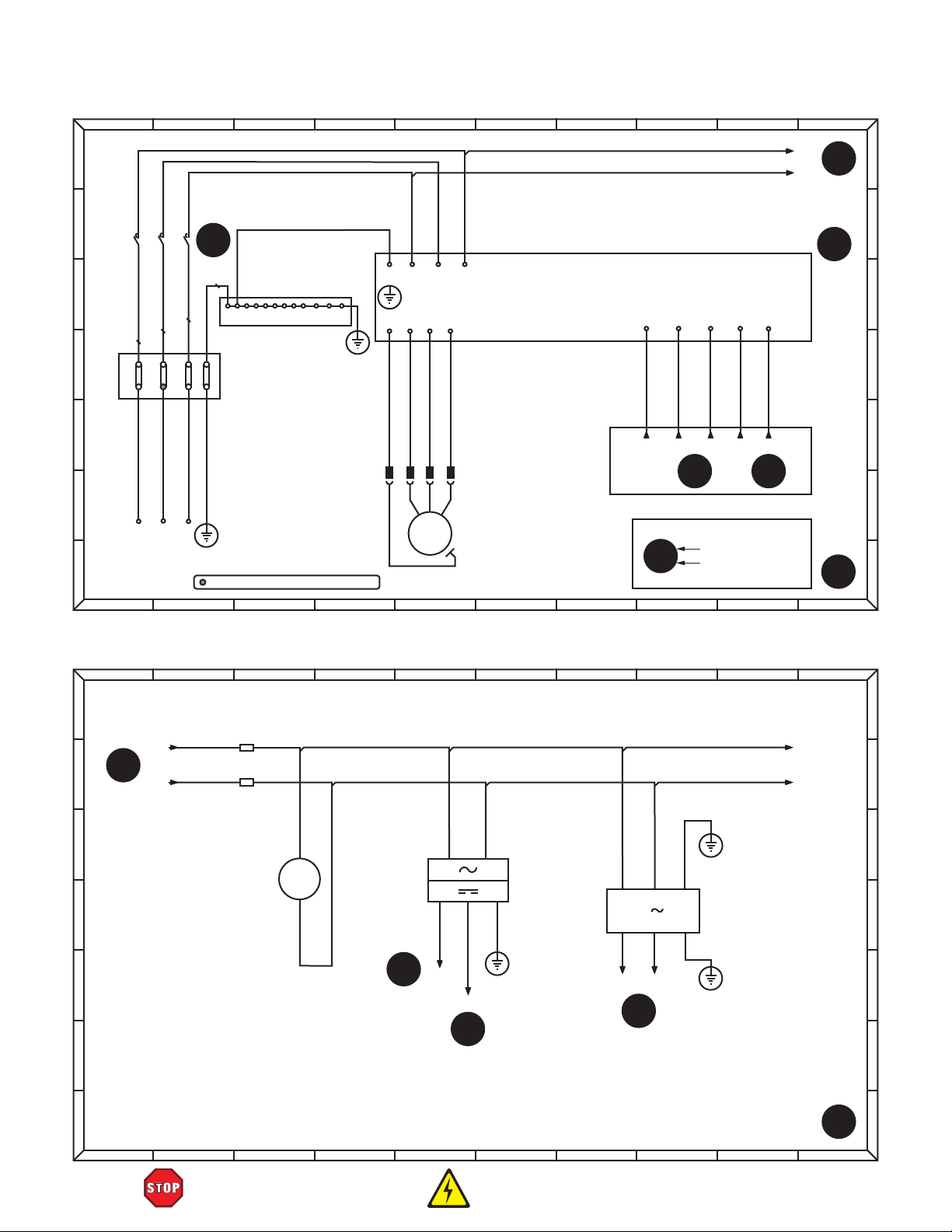
0
21
3 4
5
6
7
8
9
0 21 3 4
5
6
7
8
9
0
21
3 4
5
6
7
8
9
0 21 3 4
5
6
7
8
9
Spindle Motor Wiring Diagram
L12
L32
2
0:B
A
A
B
1
2
C
L21
L11
D
E
F
2
1
1
2
R
S
220V
3-PHASE
G
POWER
SUPPLY
KM1
5
3
4
L31
6
5:F
6
PE
1 2 3 4 5 678 9 10 11 12
3
4
TC-604
3
4
CHASSIS
GROUND
60A
PE
GND
PE
R/L1 S/L2 T/L3PE
U WVPE
U
W
V
MI1 MI3 MI4 MI5
ROTA SPEED 2
ROTA SPEED 1
SPINDLE FWD
MI1
MI3 MI4 MI5
ROTA SPEED 3
5
6:B
DCM
TERMINAL
COMMON
DCM
5
6:C
VFD
RICHAUTO DSP B18
T
PE
GND
= For phase converter wild wire (if used)
M
3~
SPINDLE
MOTOR
PE
KEY
2:E
4
Diagram Number
Frame Location
Reference
5
6:B
1
B
C
D
E
F
G
Power Components Wiring Diagram
A
FU1
A
10A
2
B
1
9:A
L12
L32
1
2
1
L13
L33
B
FU2
10A
4
C
FM
ELECTRICAL
CABINET FAN
D
M
1~
1
24VDC
POWER
2
SUPPLY
5
E
7:G
24V+
+
L
24V−
5
N
L
N G
−
G
3
2
L
N G
PE
GND
L14 L34
3
0:A
PE
GND
LB1 20A
EMI FILTER
5
PE
GND
7:G
F
G
2
C
D
E
F
G
-64-
READ ELECTRICAL SAFETY
ON PAGE 63!
Model G0932 (Mfd. Since 02/21)
Page 67

A
0
21
3 4
5
6
7
8
9
0 21 3 4
5
6
7
8
9
21
0 21 3 4
5
6
7
8
9
B
C
D
E
F
2
L14
6:D
2
L34
7:E
RICHAUTO
DSP B18
5
2:C
XP+
PUL+
X-AXIS
STEPPER
DRIVER
Stepper Motors Wiring Diagram
220VAC
110VAC
11
L15
5
2:D
XP−
XD−
XD+
PUL−
DIR+
XA− XA+ XB− XB+ Y1A−
DIR−
12
110VAC
A+
10
11 12 11
L35
PE
GND
110VAC
B−
B+A−
TRANSFORMER
11
12
6
PUL−
PUL+
Y-AXIS 1
STEPPER
DRIVER
DIR+
A
B
12
RICHAUTO DSP B18
YD+
DIR+
Y2A−
YD
A−
5
2:E
−
DIR−
Y2A+
L15
A+
L35
PE
110VAC
110VAC
B−
B+
Y2B−
RICHAUTO DSP B18
5
2:E
ZP−
ZP+
8
GND
PUL+
Z-AXIS
Y2B+
STEPPER
DRIVER
2:F
ZD+
ZD
PUL−
DIR−
DIR+
ZA− ZA+ ZB− ZB+
5
DIR−
A−
L15
Y1A+
110VAC
A+
L35
110VAC
B−
Y1B−
PE
GND
B+
Y1B+
5
2:D
YP+
7
Y-AXIS 2
STEPPER
DRIVER
PUL+
YP−
PUL−
−
110VAC
A+
L35
L15
110VAC
B−
B+A−
PE
GND
9
4
0:B
4
0:B
C
D
E
F
CD+
DIR+
2:G
CD
Y-AXIS 1
MOTOR
3 4
5
−
110VAC
110VAC
DIR−
A+
B−
B+A−
CA−CA+ CB− CB+
M
2~
M
2~
PE
10
GND
G
0
A
B
9:C
C
MOTOR
L35
3
L15
X-AXIS
M
2~
RICHAUTO DSP B18
5
2:F
CP−
CP+
D
PUL−
PUL+
E
C-AXIS
STEPPER
DRIVER
F
C-AXIS
MOTOR
Y-AXIS 2
MOTOR
5
CONNECTIONS FOR 4-WIRE AND 8-WIRE STEPPER MOTORS
M
2~
6
4-WIRE 8-WIRE
A+
A−
B+
B−
A+
A−
B+
B−
7
Z-AXIS
MOTOR
M
2~
8
3
G
9
A
B
C
D
E
F
G
Model G0932 (Mfd. Since 02/21)
G
4
READ ELECTRICAL SAFETY
-65-
ON PAGE 63!
Page 68

0
21
3 4
5
6
7
8
9
0 21 3 4
5
6
7
8
9
0
21
3 4
5
6
7
8
9
0 21 3 4
5
6
7
8
9
Interface Board Wiring Diagram
A
RICHAUTO
DSP B18
B
Y1 (S0)
Y2 (S1)
Y3 (S2)
Y4 (S3)
Y5
MI1
MI3
MI4
MI5
1
7:E
VFD
1
3:C
A
B
Y6
Y7
STEPPER DRIVERS
C
D
E
F
X
Y
Z
C
G
3
0:D
3
5:D
3
7:D
4
2:C
XP+
XP−
XD+
XD−
YP+
YP−
YD+
YD−
ZP+
ZP−
ZD+
ZD−
CP+
CP−
CD+
CD−
5V
PULSE
DIR
SHIELD
5V
PULSE
DIR
SHIELD
5V
PULSE
DIR
SHIELD
5V
PULSE
DIR
SHIELD
X-AXIS Y-AXIS Z-AXIS C-AXIS
Y8
(24VDC)
OUTPUT SIGNAL
X1 (XH)
X0
X2 (YH)
X3 (ZH)
X4 (TS)
X5
X6
X7
INPUT SIGNAL
X8
24V
GND
SHIELD
24V
GND
DC24V
Y0
1
8:E
PROXIMITY
DCMGND
SWITCHES
Z0
C0
3 3 3 3
1
2
1
2
1
2
2
4:E
24V+
24V−
2
5:E
TOOL
SETTER
CUTT
1
2
PE
GND
C
D
E
F
1
G
5
Contactor Wiring Diagram
A
L11
B
L1-1
SB0-1
LIMIT SWITCH
11
12
L1-2
SB0-2
LIMIT SWITCH
C
D
6
6:F
E
F
SB2
ON BUTTON
11
12
L1-3
EMERGENCY
11
STOP BUTTON
12
L1-4
13
14
L1-4
13
14
L1-5
L1-5
KM1
L3-1 L3-2
A1
A2
L1-5
X1
X2
SB1
KM1
SB2
ON BUTTON
LAMP
6
5:F
6
5:E
L31
1
3
G
13
5
2
1
4
1:B
6
14
6
6:D
6
A
B
C
D
E
F
G
-66-
READ ELECTRICAL SAFETY
ON PAGE 63!
Model G0932 (Mfd. Since 02/21)
Page 69

Electrical Components
Figure 85. Electrical cabinet components (left).
Figure 86. Electrical cabinet components (right).
Model G0932 (Mfd. Since 02/21)
READ ELECTRICAL SAFETY
ON PAGE 63!
-67-
Page 70

Electrical Components (Cont.)
Figure 87. Contactor, fuse holders, terminal
blocks, and EMI filter.
Figure 88. Right electrical cabinet stepper
drivers.
Figure 90. VFD and 24VDC power supply.
Figure 91. Transformer.
Figure 89. Interface board and limit switch.
-68-
READ ELECTRICAL SAFETY
ON PAGE 63!
Figure 92. Main power terminals and limit
switch.
Model G0932 (Mfd. Since 02/21)
Page 71

Electrical Components (Cont.)
Figure 96. C-axis proximity switch and stepper
Figure 93. Spindle motor.
motor.
Figure 94. X-axis proximity switch.
Figure 95. Oiler system.
Model G0932 (Mfd. Since 02/21)
Figure 97. Y-axis proximity switch.
READ ELECTRICAL SAFETY
ON PAGE 63!
-69-
Page 72

113
122
124
125
129
148
169
167
153
153
149
146
SECTION 9: PARTS
We do our best to stock replacement parts when possible, but we cannot guarantee that all parts shown
are available for purchase. Call (800) 523-4777 or visit www.grizzly.com/parts to check for availability.
Frame & Bed
140
138
126
161-3
161-4
161-1
161-2
171
170
160
161
161-5
135
131
121
142
130
133
151
150
137
127
136
111
173
117-1
106
152
117
121
131
122
143
130
135
160
134
137
140
127
138
126
116
117-1
117
164
134
144
130
135
101
162
137
163
120
131
165
103
153
145
114
117-1
159
148
104
118
110
139
117
105
132
119
135
116
156
157
137
147
102
133
155
158
128
141
112
131
135
130
136
156
154
109
172
107
168
108
-70 -
BUY PARTS ONLINE AT GRIZZLY.C OM!
Scan QR code to visit our Parts Store.
170
171
166
166-1
166-5
166-4
166-6
166-2
166-3
123
Model G0932 (Mfd. Since 02/21)
115
Page 73

REF P ART # DE SCRIPTION RE F PART # DESCRIPTI ON
Frame & Bed Parts List
101 P0932101 MACHI NE BODY 143 P0932143 BUTTON HD CAP SCR M5-. 8 X 12
102 P0932102 LINEAR SUPPORT RAIL 16 X 2000MM 144 P0932144 CAP SCREW M4-.7 X 16
103 P0932103 SUPPORT RAIL CARRIAGE 145 P0932145 CAP SCREW M6-1 X 20
104 P0932104 3-JAW SCROLL CHUCK 200MM 146 P0932146 CAP SCREW M10-1.5 X 30
105 P0932105 CHUCK MOUNTING PLATE 147 P0932147 CAP SCREW M10-1.5 X 30
106 P0932106 ELECTRICAL CABINET 148 P0932148 CAP SCREW M8-1.25 X 20
107 P0932107 ELECTRICAL CABINET DIVIDER 149 P0932149 CAP SCREW M10-1.5 X 30
108 P0932108 ELECTRI CAL CABI NET DOOR, RI GHT 150 P0932150 CABLE CARRIER TRACK BRACKET
109 P0932109 ELECTRICAL CABINET DOOR, LEFT 151 P0932151 CABL E CA RRI ER TRA CK
110 P0932110 DUST COVER, RIGHT 152 P0932152 BUTTON HD CAP SCR M5-. 8 X 12
111 P0932111 DUST COVER, LEFT 153 P0932153 CAP SCREW M5-.8 X 12
112 P0932112 DUST COVER, REAR 154 P0932154 VACUUM ELBOW FITTING 2"
113 P0932113 GEARBOX REDUCER MOUNT 155 P0932155 VACUUM LI NE 2"
114 P0932114 TAI LSTOCK MOUNT 156 P0932156 HOSE CLAMP 2"
115 P0932115 VACUUM CONTROL VALVE 157 P0932157 I NSIDE JAW SET (3-PC)
116 P0932116 LINEAR GUI DEWAY PMI MSA20-3060 158 P0932158 FENDER WASHER 10 X 45 X 3
117 P0932117 LEVELING FOOT M16-2 159 P0932159 VACUUM HOSE 5-WAY SPLITTER
117-1 P0932117-1 HE X NUT M1 6- 2 160 P0932160 VACUUM PORT W/PLUG
118 P0932118 LIVE CENTER 161 P0932161 HOLD-DOWN CLAMP
119 P0932119 TAILSTOCK 161-1 P0932161-1 CLAMP PLATE
120 P0932120 SUPPORT RAIL LOCK 161-2 P0932161-2 HEX BOLT M8-1. 25 X 50
121 P0932121 ELECTRICAL COOLING FAN DP200A 161-3 P0932161-3 WI NG NUT M8- 1. 2 5
122 P0932122 FAN COVER 161-4 P0932161-4 FL AT WA SHE R 8MM
123 P0932123 BALL VALVE DN32 161-5 P0932161-5 T-BOLT M8-1. 25 X 80
124 P0932124 BALL VALVE DN40 162 P0932162 OUTSI DE JAW SET (3-PC)
125 P0932125 VACUUM PRESSURE GAUGE 163 P0932163 CHUCK KEY
126 P0932126 T-SLOT TRACK 2500MM 164 P0932164 GASKET TUBING
127 P0932127 VACUUM TABLE SLAT 165 P0932165 VACUUM HOSE 3-WAY SPLITTER
128 P0932128 GEARBOX REDUCER NMRV75 166 P0932166 VACUUM PUMP ASSEMBLY
129 P0932129 STEPPER MOTOR FL86STH118A-22-LC 166-1 P0932166-1 VACUUM PUMP 10HP 220V 3-PH
130 P0932130 LIMIT STOP BUMPER 166-2 P0932166-2 PLEXI GLASS COVER W/RUBBER SEAL
131 P0932131 LIMIT STOP BRACKET 166-3 P0932166-3 V ACUUM P UMP FI L TER
132 P0932132 Y-AXIS PROXIMITY SWITCH BRACKET 166-4 P0932166-4 V ACUUM FI L TER B AS E
133 P0932133 HELICAL RACK 1.25M, 670MM 166-5 P0932166-5 THREADED PIPE 2 IPS X 3"
134 P0932134 HELICAL RACK 1.25M, 300MM 166-6 P0932166-6 ELBOW FITTI NG 2 IPS
135 P0932135 CAP SCREW M6-1 X 20 167 P0932167 LOCK WASHER 10MM
136 P0932136 CAP SCREW M6-1 X 20 168 P0932168 ON BUTTON SCH XB2BW33M1C 22MM GRN
137 P0932137 CAP SCREW M10-1.5 X 30 169 P0932169 E-STOP BUTTON SCH XB4BS542 22MM RED
138 P0932138 FLAT HD SCR M5-. 8 X 25 170 P0932170 DOOR HINGE
139 P0932139 BUTTON HD CAP SCR M5-. 8 X 12 171 P0932171 FLAT HD CAP SCR M5-.8 X 12
140 P0932140 CAP SCREW M6-1 X 20 172 P0932172 DOOR HANDLE W/ LOCK
141 P0932141 BUTTON HD CAP SCR M5-. 8 X 12 173 P0932173 CABLE CARRIER
142 P0932142 BUTTON HD CAP SCR M5-. 8 X 12
Model G0932 (Mfd. Since 02/21)
BUY PARTS ONLINE AT GRIZZLY.C OM!
Scan QR code to visit our Parts Store.
-71-
Page 74

351
325
346
344
403
Gantry & Spindle
205
216
210
220
218
352
348
209
215
347
203
324
214
202
348
219
352
315
316
317
318
305
319
307
303
324
347
338
321
343
337
315
343
323
320
326
344
339
306
308
342
345
328
323
322
335
213
336
329
314
306
341
310
333
311
340
309
313
312
334
327
204
350
330
331
332333
301
302
330
304
349
412
217
416
410
415
408
206
415
412
406
407
409
413
405
218
411
208
401
414
201
413
218
413
207
402
222
221
223
212
224
225
414
211
407
409
215
220
202
406
213
415
219
209
216
210
412
404
-72-
BUY PARTS ONLINE AT GRIZZLY.C OM!
Scan QR code to visit our Parts Store.
405
415
408
416
410
412
Model G0932 (Mfd. Since 02/21)
Page 75

REF PART # DES CRIP TION REF PART # DES CRIP TION
Gantry & Spindle Parts List
201 P0932201 GANTRY BEAM 323 P0932323 SYNCHRONOUS WHEE L Z2 0
202 P0932202 LINEAR GUIDEWAY PMI MSA20-1840 324 P0932324 FAN COVER
203 P0932203 HELICAL RACK 1. 25M, 670MM 325 P0932325 DUST SHI ELD
204 P0932204 HELICAL RACK 1. 25M, 470MM 326 P0932326 PROXIMI TY S WI TCH OMRON TL-Q5MCI -Z
205 P0932205 CABLE CARRIER TRACK 1050MM 327 P0932327 Z-AXIS PROXIMITY SWITCH BRACKET
206 P0932206 GANTRY ACCESS PANEL, LEFT 328 P0932328 PROXIMI TY S WI TCH OMRON TL-Q5MCI -Z
207 P0932207 GANTRY ACCESS PANEL, RIGHT 329 P0932329 BALL SCREW
208 P0932208 GANTRY CABLE ACCESS FAIRING 330 P0932330 CAP SCREW M8-1.25 X 35
209 P0932209 LIMIT STOP BUMPER 331 P0932331 CAP SCREW M8-1.25 X 20
210 P0932210 LIMIT STOP BRACKET 332 P0932332 CAP SCREW M6-1 X 20
211 P0932211 OILER SYSTEM PUMP 333 P0932333 CAP SCREW M6-1 X 20
212 P0932212 X-AXIS PROXIMITY SWI TCH BRACKET 334 P0932334 CAP SCREW M6-1 X 20
213 P0932213 CAP SCREW M6-1 X 20 335 P0932335 CAP SCREW M6-1 X 20
214 P0932214 CAP SCREW M6-1 X 20 336 P0932336 CAP SCREW M4-.7 X 16
215 P0932215 CAP SCREW M10-1.5 X 30 337 P0932337 CAP SCREW M6-1 X 20
216 P0932216 CAP SCREW M10-1.5 X 30 338 P0932338 CAP SCREW M6-1 X 20
217 P0932217 BUTTON HD CAP SCR M5- . 8 X 12 339 P0932339 CAP SCREW M8-1.25 X 20
218 P0932218 BUTTON HD CAP SCR M5- . 8 X 12 340 P0932340 CAP SCREW M6-1 X 20
219 P0932219 X-AXIS MOVEMENT LABEL 341 P0932341 CAP SCREW M5-.8 X 25
220 P0932220 Y-AXIS MOVEMENT LABEL 342 P0932342 CAP SCREW M8-1.25 X 20
221 P0932221 PHLP HD SCR M4-. 7 X 12 343 P0932343 CAP SCREW M5-.8 X 25
222 P0932222 LOCK WASHER 4MM 344 P0932344 B UTTON HD CA P S CR M5- . 8 X 12
223 P0932223 FLAT WASHER 4MM 345 P0932345 CAP SCREW M4-.7 X 16
224 P0932224 BUTTON HD CAP SCR M6- 1 X 16 346 P0932346 CAP SCREW M5-.8 X 12
225 P0932225 FLAT WASHER 6MM 347 P0932347 BUTTON HD CAP SCR M5- . 8 X 12
301 P0932301 SPINDLE MOTOR HSD 4HP 220V 3-PH 348 P0932348 BUTTON HD CAP SCR M5-.8 X 12
302 P0932302 SPINDLE MOTOR PLATE 349 P0932349 CAP SCREW M5-.8 X 45
303 P0932303 SPINDLE COVER, UPPER 350 P0932350 HEX NUT M5-. 8
304 P0932304 DUST SHOE 351 P0932351 Z-AXIS TOOL SETTER
305 P0932305 DUST HOSE CLAMP 352 P0932352 Z-AXIS MOVEMENT LABEL
306 P0932306 GUIDEWAY CARRIAGE MSA20S 401 P0932401 GANTRY COLUMN, RIGHT
307 P0932307 DRIVE GEARBOX MOUNT 402 P0932402 GANTRY COLUMN, LE FT
308 P0932308 BALL SCREW END SUPPORT, UPPER 403 P0932403 COLUMN COVER, RI GHT
309 P0932309 OILER MANIFOLD 404 P0932404 COLUMN COVER, LE FT
310 P0932310 X-AXIS MOUNTING PLATE 405 P0932405 GUIDEWAY CARRIAGE MSA20S
311 P0932311 Z-AXIS MOUNTING PLATE 406 P0932406 STEPPER MOTOR FL86STH118A-22-LC
312 P0932312 LINEAR GUIDEWAY PMI MSA20S-500 407 P0932407 DRIVE GEARBOX 1.25M
313 P0932313 FLANGE BALL NUT 408 P0932408 TIMING BELT HTD 550-5M
314 P0932314 BALL SCREW END SUPPORT, LOWER 409 P0932409 SYNCHRONOUS WHEEL Z18
315 P0932315 STEPPER MOTOR FL86STH118A-22-LC 410 P0932410 GEARBOX COVER
316 P0932316 SYNCHRONOUS WHEE L Z1 8 411 P0932411 PROXIMI TY S WI TCH OMRON TL-Q5MCI -Z
317 P0932317 TIMING BELT HTD 550-5M 412 P0932412 BUTTON HD CAP SCR M5- . 8 X 12
318 P0932318 DRIVE GEARBOX 1.25M 413 P0932413 CAP SCREW M5-.8 X 25
319 P0932319 GEARBOX COVER 414 P0932414 CAP SCREW M10-1.5 X 30
320 P0932320 STEPPER MOTOR MOUNTING PLATE 415 P0932415 CAP SCREW M4-.7 X 16
321 P0932321 STEPPER MOTOR BRACKET 416 P0932416 BUTTON HD CAP SCR M5- . 8 X 12
322 P0932322 TIMING BELT HTD 310-5M
Model G0932 (Mfd. Since 02/21)
BUY PARTS ONLINE AT GRIZZLY.C OM!
Scan QR code to visit our Parts Store.
-73 -
Page 76

542
544
545
Electrical & Accessories
544
559
508
543
501
544
509
557
546 547
502
544
558
545
546
544
545
546
553
503
555
544 544
504
510
556
514
505
515 516 517 518 519 520 521
544 544 544
505 505
511
548
549
550
551
505
512
507
554
544
506
544
552
513
508
509
557
-74 -
524
522 523
525
BUY PARTS ONLINE AT GRIZZLY.C OM!
Scan QR code to visit our Parts Store.
526
527
528
529
530
532
531
537
533
538
534
539
540
535
541
Model G0932 (Mfd. Since 02/21)
536
Page 77

REF P ART # DE SCRI PTION RE F PART # DES CRIP TION
Electrical & Accessories Parts List
501 P0932501 CONTACTOR SCH LC1D32M7C 220V 32A 531 P0932531 COLLET ER25 1/2"
502 P0932502 FUSE HOLDER YHDA RT18-32X 10A 532 P0932532 COLLET ER25 4MM
503 P0932503 TERMINAL BAR 12P DIN38 12-24G 533 P0932533 COLLET ER25 6MM
504 P0932504 EMI FILTER TORUN 3N-20A-U 534 P0932534 SPOILBOARD CUTTER 6 X 22MM
505 P0932505 STEPPER DRIVER YAKO YKA2811MA 535 P0932535 V-GROOVE CUTTER 6 X 22MM
506 P0932506 VFD DELTA VFD037E23A 240V 3-PH 536 P0932536 DOOR KEY (2-PC)
507 P0932507 24V DC POWER SUPPLY MEANWELL LRS-75-24 537 P0932537 P ROX I MI TY S WI TCH OMRO N TL- Q5 MCI -Z
508 P0932508 LIMIT SWI TCH PANASONIC AZ-7311 538 P0932538 HEX WRENCH 3MM
509 P0932509 LIMIT SWI TCH BRACKET 539 P0932539 HEX WRE NCH 4MM
510 P0932510 INTERFACE BOARD RICHAUTO A1X/B1X 540 P0932540 HEX WRENCH 5MM
511 P0932511 TRANSFORMER WIN JBK5-1200VA/A 220V/110V 541 P0932541 HEX WRENCH 6MM
512 P0932512 TERMINAL BAR 12P M4 X 12 X 12 TM4 542 P0932542 FUSE 10A 500V 10MM TIME-DELAY, CERAMIC
513 P0932513 TERMINAL BLOCK TC-604 60A 543 P0932543 CAP SCREW M4-.7 X 30
514 P0932514 SPINDLE POWER CORD TRVVP 18G 4W 544 P0932544 PHLP HD SCR M4-.7 X 12
515 P0932515 X-AXIS MOTOR CORD TRVVP 19G 4W 545 P0932545 LOCK WASHER 4MM
516 P0932516 Y-AXIS1 MOTOR CORD TRVVP 19G 4W 546 P0932546 FLA T WAS HER 4 MM
517 P0932517 Y-AXIS2 MOTOR CORD TRVVP 19G 4W 547 P0932547 HEX NUT M4- . 7
518 P0932518 Z-AXI S MOTOR CORD TRVVP 19G 4W 548 P0932548 CAP SCREW M6-1 X 16
519 P0932519 C-AXI S MOTOR CORD TRVVP 19G 4W 549 P0932549 LOCK WASHER 6MM
520 P0932520 Y-AXIS LIMIT CORD TRVV 22G 4W 550 P0932550 FLAT WASHER 6MM
521 P0932521 C-AXI S LIMIT CORD TRVV 22G 4W 551 P0932551 HEX NUT M6- 1
522 P0932522 AXES LIMIT CORD TRWP 22G 7W 552 P0932552 WI RE LOOM 50 X 1370MM
523 P0932523 OILER PUMP CORD TRVV 20G 2W 553 P0932553 WI RE LOOM 50 X 480MM
524 P0932524 50 PIN CABLE 26G 50W 72" 554 P0932554 WIRE LOOM 50 X 280MM
525 P0932525 COLLET WRENCH ER25 555 P0932555 WIRE LOOM 50 X 230MM
526 P0932526 WRENCH 27 X 30MM OPEN-ENDS 556 P0932556 WIRE LOOM 50 X 200MM
527 P0932527 ENGRAVING BIT 1/8" (20-PC) 557 P0932557 GRO UNDI NG CA BL E
528 P0932528 USB-B CABLE 28G 4W 36" 558 P0932558 DI N RA I L DI N3 8
529 P0932529 DSP CONTROLLER RICHAUTO B18 559 P0932559 ELECTRI CAL MOUNTING BOARD
530 P0932530 COLLET ER25 1/8"
Model G0932 (Mfd. Since 02/21)
BUY PARTS ONLINE AT GRIZZLY.C OM!
Scan QR code to visit our Parts Store.
-75-
Page 78

REF PART # DES CRIP TION REF PART # DES CRIPTI ON
Labels & Cosmetics
609
608
612
611
601
602
603
610
611
607
606
605
601 P0932601 MACHINE ID LABEL 607 P0932607 CUTTI NG HAZARD CNC LABEL
602 P0932602 MODEL NUMBER LABEL 608 P0932608 DISCONNECT HARDWI RED LABEL
603 P0932603 COMBO WARNI NG LABEL 609 P0932609 READ MANUAL LABEL
604 P0932604 OIL RESERVOIR LABEL 610 P0932610 DO NOT OPEN DOOR CNC LABEL
605 P0932605 TOUCH-UP P AI NT, G RI ZZLY GREEN 611 P0932611 ELECTRICITY HAZARD LABEL
606 P0932606 TOUCH-UP P AI NT, G RI ZZLY BEI G E 612 P0932612 GRIZZLY NAMEPLATE, LARGE
Safety labels help reduce the risk of serious injury caused by machine hazards. If any label comes
off or becomes unreadable, the owner of this machine MUST replace it in the original location
before resuming operations. For replacements, contact (800) 523-4777 or www.grizzly.com.
604
-76-
BUY PARTS ONLINE AT GRIZZLY.C OM!
Scan QR code to visit our Parts Store.
Model G0932 (Mfd. Since 02/21)
Page 79

Grizzly Industrial, Inc. warrants every product it sells for a period of 1 year to the original purchaser from
the date of purchase. This warranty does not apply to defects due directly or indirectly to misuse, abuse,
negligence, accidents, repairs or alterations or lack of maintenance. This is Grizzly’s sole written warranty
and any and all warranties that may be implied by law, including any merchantability or fitness, for any particular purpose, are hereby limited to the duration of this written warranty. We do not warrant or represent
that the merchandise complies with the provisions of any law or acts unless the manufacturer so warrants.
In no event shall Grizzly’s liability under this warranty exceed the purchase price paid for the product and
any legal actions brought against Grizzly shall be tried in the State of Washington, County of Whatcom.
We shall in no event be liable for death, injuries to persons or property or for incidental, contingent, special,
or consequential damages arising from the use of our products.
The manufacturers reserve the right to change specifications at any time because they constantly strive to
achieve better quality equipment. We make every effort to ensure that our products meet high quality and
durability standards and we hope you never need to use this warranty.
In the event you need to use this warranty, contact us by mail or phone and give us all the details. We will
then issue you a “Return Number,’’ which must be clearly posted on the outside as well as the inside of
the carton. We will not accept any item back without this number. Proof of purchase must accompany the
merchandise.
Please feel free to write or call us if you have any questions about the machine or the manual.
Thank you again for your business and continued support. We hope to serve you again soon.
To
you can
applicable information for
WARRANTY & RETURNS
take advantage of this warranty, you must register it at https://www.grizzly.com/forms/warranty, or
scan the QR code below to be automatically directed to our warranty registration page. Enter all
the product.
WARRANTY
Page 80

 Loading...