

Page 1

READ THIS FIRST
Model G0925
***IMPORTANT UPDATE***
For Machines Mfd. Since 02/20
and Owner's Manual Printed 02/20
For questions or help with this product contact Tech Support at (570) 546-9663 or techsupport@grizzly.com
The following changes were recently made since the owner's manual was printed:
• Factory replaced depth stop bracket with a chuck guard.
• Inventory list has been revised.
• Assembly section has been revised.
Aside from this information, all other content in the owner's manual applies and MUST be read and understood for your own safety. IMPORTANT: Keep this update with the owner's manual for future reference.
For questions or help, contact our Tech Support at (570) 546-9663 or techsupport@grizzly.com.
Revised Parts Breakdown & List
21
81-5
81-8
81-1
81-14
81-4
81-3
81-9
81
81-10
81-2
81-12
81-13
81-6
81-7
81-11
REF PART # DESCRIPTION
21 P0925021 FLAT WASHER 6MM
81 P0925081 CHUCK GUARD ASSEMBLY
81-1 P0925081-1 CHUCK GUARD SEAT
81-2 P0925081-2 LOWER GUARD
81-3 P0925081-3 TAP SCREW M3.5 X 5
81-4 P0925081-4 PHLP HD SCR M4-.7 X 30
81-5 P0925081-5 HEX NUT M4-.7
81-6 P0925081-6 LOCK NUT M4-.7
81-7 P0925081-7 PHLP HD SCR M4-.7 X 20
81-8 P0925081-8 EXTENSION SPRING 1 X 6 X 20
81-9 P0925081-9 HINGE BRACKET
81-10 P0925081-10 UPPER GUARD
81-11 P0925081-11 WING NUT M5-.8
81-12 P0925081-12 HEX BOLT M5-.8 X 10
81-13 P0925081-13 PHLP HD SCR M3-.5 X 10
81-14 P0925081-14 HEX NUT M3-.5
Revised Needed for Setup
Description Qty
Phillips Head Screwdriver #1 ............................ 1
Wrench or Sockets 4, 5.5, 10mm
................1 Ea.
COPYRIGHT © MAY, 2020 BY GRIZZLY INDUSTRIAL, INC.
WARNING: NO PORTION OF THIS MANUAL MAY BE REPRODUCED IN ANY SHAPE
OR FORM WITHOUT THE WRITTEN APPROVAL OF GRIZZLY INDUSTRIAL, INC.
#CS21123 PRINTED IN CHINA
Page 2

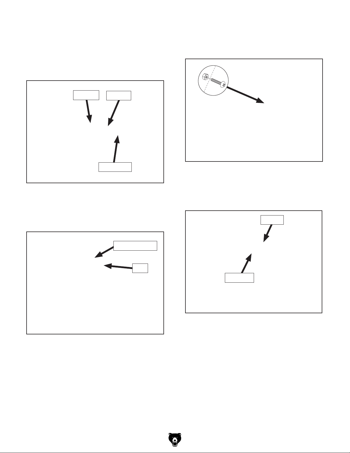
Revised Inventory List
Box 1 (Figure 1) Qty
K. Pointer ........................................................ 1
. Threaded Depth Rod Assembly ................. 1
L
. Chuck Guard Assembly ............................. 1
M
. Chuck Guard Seat Assembly ..................... 1
N
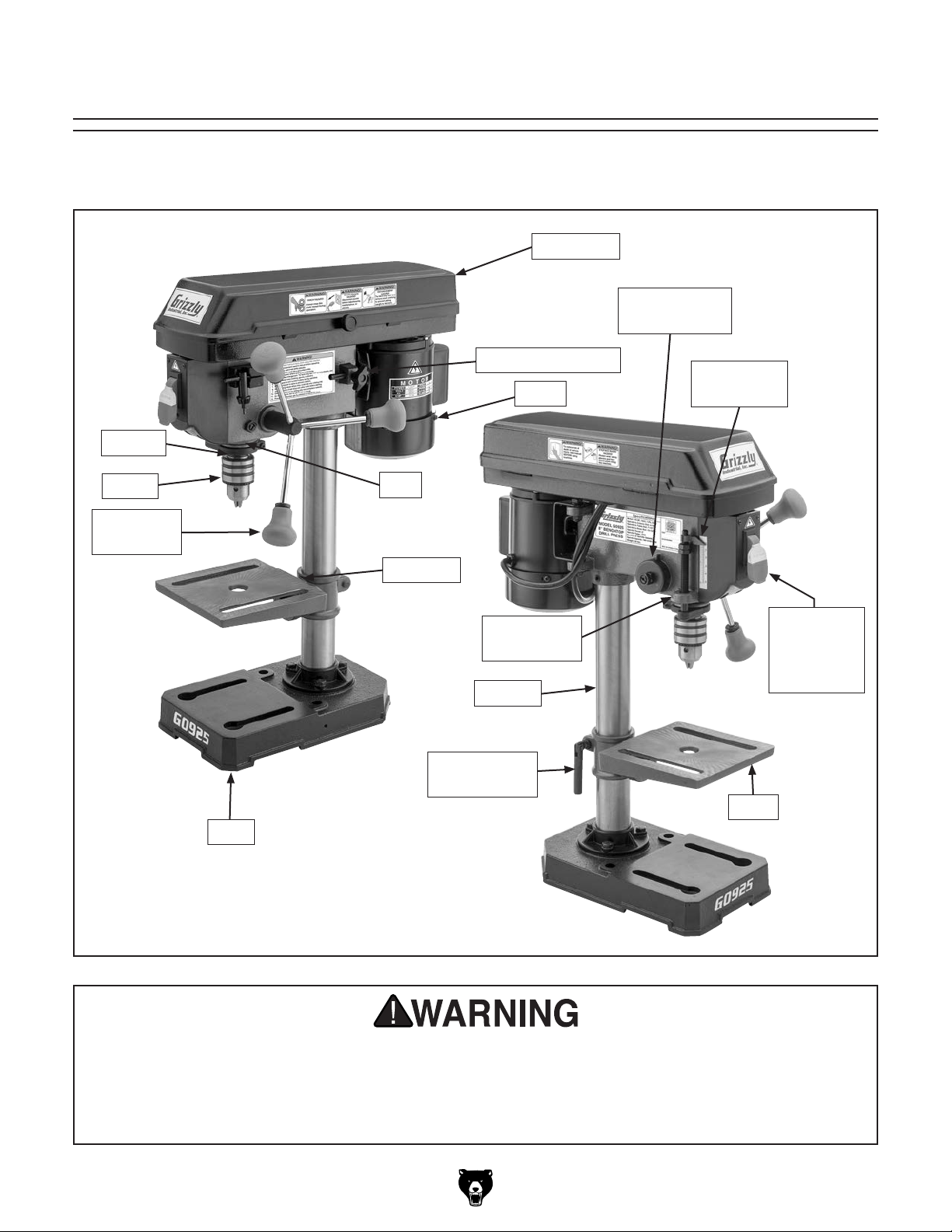
Attach chuck guard to chuck guard seat
6.
using fasteners removed in Step 5 (see
Figure 4).
K
L
Figure 1. Box 1 additions.
M
N
Revised Assembly Steps
Perform Steps 1–4 of Assembly on Page 15 of
owner's manual. Then follow the steps below to
complete the assembly process.
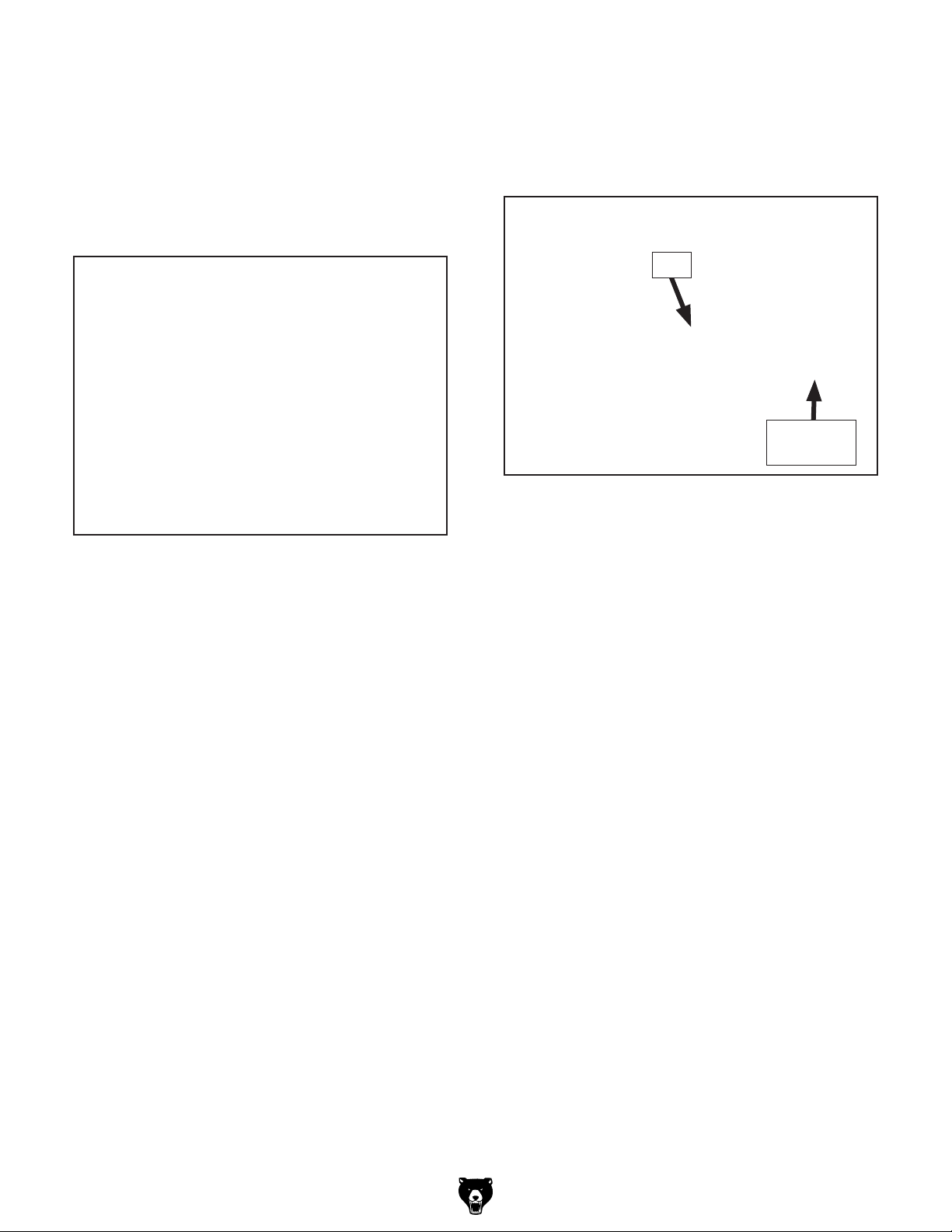
5. Remove (2) pre-installed tap screws, Phillips
head screw, and hex nut (see Figure 2) from
chuck guard seat.
Figure 3. Aligning chuck guard to chuck guard
seat.
Tap Screws
Hex Nut
Phillips Head
Screw
Figure 2. Location of chuck guard seat screws.
Figure 4. Attaching chuck guard to chuck guard
seat.
-2-
Model G0925 (Mfd. Since 2/20)
Page 3
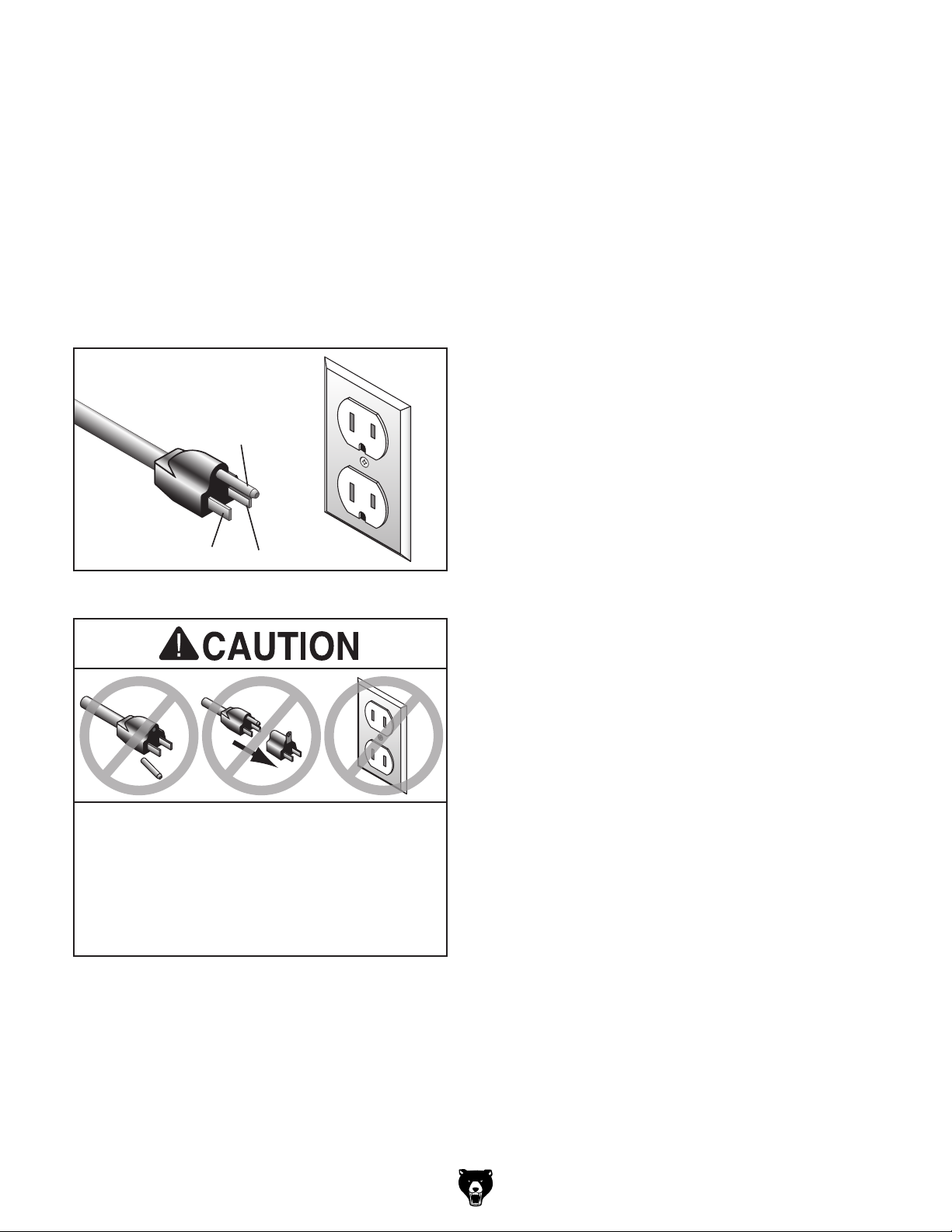
Remove (2) M10-1.5 hex nuts, (1) M6-1 hex
7.
nut and (1) 6mm flat washer from depth rod.
Pull bottom of chuck guard forward to open
8.
and attach depth rod to guard with M6-1 hex
nut and 6mm flat washer (see Figure 5).
10. With chuck guard around quill, tighten Phillips
head screw and hex nut until guard is snug
(see Figure 7).
Hex Nut
Figure 5. Attaching depth rod to chuck guard.
Close guard and insert depth rod through
9.
mounting hole until guard fits around drill
press quill (see Figure 6).
Washer
Depth Rod
Mounting Hole
Figure 7. Attaching chuck guard to quill.
Thread (2) M10-1.5 hex nuts from Step 7
11.
onto depth rod, and snap on pointer so it
points at zero (see Figure 8).
Pointer
Quill
Figure 6. Inserting depth rod through mounting
hole.
Hex Nuts
Figure 8. Attaching pointer to depth rod.
12. Open chuck guard.
13. Use acetone or lacquer thinner to clean
spindle and chuck mating surfaces.
14. Retract chuck jaws completely.
Model G0925 (Mfd. Since 2/20)
-3-
Page 4
15. Push chuck onto spindle taper, then use
a wood block and hammer or mallet to hit
chuck once with moderate force as shown in
Figure 9.
Note: Hitting chuck directly with a steel ham-
mer may damage chuck, making it unsafe to
use.
16. Attempt to separate spindle and chuck by
hand—if they separate, repeat Steps 13–15.
17
. Thread (3) downfeed handles into downfeed
hub, as shown in Figure 10.
Hub
Downfeed
Handle
Figure 10. Downfeed handles installed in hub.
Figure 9. Using block of wood and hammer to
tap chuck onto spindle taper.
-4-
Model G0925 (Mfd. Since 2/20)
Page 5

MODEL G0925
8" BENCHTOP DRILL PRESS
OWNER'S MANUAL
(For models manufactured since 02/20)
COPYRIGHT © FEBRUARY, 2020 BY GRIZZLY INDUSTRIAL, INC.
WARNING : NO PORTION OF THIS MANUAL MAY BE REPRODUCED IN ANY SHAPE
OR FORM WITHOUT THE WRITTEN APPROVAL OF GRIZZLY INDUSTRIAL, INC.
#CS20962 PRINTED IN CHINA
V1.0 2.2 0
Page 6

This manual provides critical safety instructions on the proper setup,
operation, maintenance, and service of this machine/tool. Save this
document, refer to it often, and use it to instruct other operators.
Failure to read, understand and follow the instructions in this manual
may result in fire or serious personal injury—including amputation,
electrocution, or death.
The owner of this machine/tool is solely responsible for its safe use.
This responsibility includes but is not limited to proper installation in
a safe environment, personnel training and usage authorization,
proper inspection and maintenance, manual availability and comprehension, application of safety devices, cutting/sanding/grinding tool
integrity, and the usage of personal protective equipment.
The manufacturer will not be held liable for injury or property damage
from negligence, improper training, machine modifications or misuse.
Some dust created by power sanding, sawing, grinding, drilling, and
other construction activities contains chemicals known to the State
of California to cause cancer, birth defects or other reproductive
harm. Some examples of these chemicals are:
• Lead from lead-based paints.
• Crystalline silica from bricks, cement and other masonry products.
• Arsenic and chromium from chemically-treated lumber.
Your risk from these exposures varies, depending on how often you
do this type of work. To reduce your exposure to these chemicals:
Work in a well ventilated area, and work with approved safety equipment, such as those dust masks that are specially designed to filter
out microscopic particles.
Page 7

Table of Contents
INTRODUCTION ............................................................................................................................... 2
Contact Info
Manual Accuracy
Identification
Controls & Components
Machine Data Sheet
................................................................................................................................ 2
........................................................................................................................ 2
............................................................................................................................... 3
............................................................................................................. 4
................................................................................................................... 5
SECTION 1: SAFETY
Safety Instructions for Machinery
Additional Safety for Drill Presses
SECTION 2: POWER SUPPLY
SECTION 3: SETUP
Needed for Setup
Unpacking
Inventory
Cleanup
Site Considerations
Bench Mounting
Assembly
Test Run
SECTION 4: OPERATIONS
Operation Overview.................................................................................................................. 18
Choosing Spindle Speeds
Changing Spindle Speed
Installing/Removing Drill Bits
Adjusting Depth Stop
Positioning Table
SECTION 5: ACCESSORIES
................................................................................................................................ 12
................................................................................................................................... 13
.................................................................................................................................... 13
.................................................................................................................................. 15
................................................................................................................................... 17
....................................................................................................................... 7
............................................................................................... 7
.............................................................................................. 9
...................................................................................................... 10
....................................................................................................................... 12
..................................................................................................................... 12
.................................................................................................................. 14
....................................................................................................................... 14
........................................................................................................... 18
........................................................................................................ 19
......................................................................................................... 20
.................................................................................................... 21
............................................................................................................... 21
...................................................................................................................... 22
......................................................................................................... 23
SECTION 6: MAINTENANCE......................................................................................................... 26
Schedule
Cleaning & Protecting
Lubrication
SECTION 7: SERVICE
Troubleshooting
Adjusting Spring Tension
Aligning Pulleys
SECTION 8: WIRING
Wiring Safety Instructions
Wiring Diagram
SECTION 9: PARTS
Main
Labels & Cosmetics
WARRANTY & RETURNS
.................................................................................................................................. 26
.............................................................................................................. 26
................................................................................................................................ 26
................................................................................................................... 28
........................................................................................................................ 28
......................................................................................................... 30
........................................................................................................................ 31
...................................................................................................................... 32
........................................................................................................ 32
........................................................................................................................ 33
....................................................................................................................... 34
.......................................................................................................................................... 34
................................................................................................................. 36
............................................................................................................. 37
Page 8

We stand behind our machines! If you have questions or need help, contact us with the information
below. Before contacting, make sure you get the
serial number
from the
machine ID label. This will help us help you faster.
We want your feedback on this manual. What did
you like about it? Where could it be improved?
Please take a few minutes to give us feedback.
Email: manuals@grizzly.com
We are proud to provide a high-quality owner’s
manual with your new machine!
We
instructions, specifications, drawings, and photographs
in this manual. Sometimes we make mistakes, but
our policy of continuous improvement also means
that
you receive is
slightly different than shown in the manual
If you find this to be the case, and the difference
between the manual and machine leaves you
confused or unsure about something
check our
website for an updated version. W
current
manuals and
on our web-
site at
Alternatively, you can call our Technical Support
for help. Before calling, make sure you write down
the
from
the machine ID label (see below). This information
is required for us to provide proper tech support,
and it helps us determine if updated documentation is available for your machine.
INTRODUCTION
Contact Info
and manufacture date
Grizzly Technical Support
1815 W. Battlefield
Springfield, MO 65807
Phone: (570) 546-9663
Email: techsupport@grizzly.com
Grizzly Documentation Manager
P.O. Box 2069
Bellingham, WA 98227-2069
Manual Accuracy
made every effort to be exact with the
sometimes the machine
.
,
e post
manual updates for free
www.grizzly.com.
Manufacture Date and Serial Number
Manufacture Date
Serial Number
-2-
Model G0925 (Mfd. Since 02/20)
Page 9
Identification
Become familiar with the names and locations of the controls and features shown below to better understand
the instructions in this manual.
Belt Cover
Spindle
Return Spring
Spindle
Chuck
Downfeed
Handle
Base
Quill
Tilt Scale
Table Height
Lock Handle
Belt Tension Lock
Motor
Adjustable
Depth Stop
Column
Depth Stop
Scale
ON/OFF
Switch
w/Disabling
Key
Table
For Your Own Safety Read Instruction Manual Before Operating Drill Press
a) Wear eye protection.
b) Do not wear gloves, necktie, or loose clothing.
c) Clamp workpiece or brace against column to prevent rotation.
d) Use recommended speed for drill accessory and workpiece material.
Model G0925 (Mfd. Since 02/20)
-3-
Page 10

Controls &
To reduce your risk of
serious injury, read this
entire manual BEFORE
Components
using machine.
Refer to the following figures and descriptions to
become familiar with the basic controls and components of this machine. Understanding these
items and how they work will help you understand
the rest of the manual and minimize your risk of
injury when operating this machine.
Table
E
Figure 2. Table controls.
E. Table Lock Handle: Locks table height and
rotation in position in relation to column.
Power and Speed Components
Headstock
A
B
C
D
Figure 1. Headstock controls.
A. Adjustable Depth Stop: Stops spindle travel
at predetermined depth.
B. Depth Scale: Indicates drilling depth and position of depth stop.
C. Downfeed Handles: Move spindle down when
pulled down. Spindle automatically returns to top
position when released.
H
F
J
Figure 3. Control panel.
F. Spindle Pulley: Holds drive belt and transfers
motor power to spindle.
G. Drive Belt: Controls spindle speed.
H. Motor Pulley: Transfers motor power to drive
belt at different speeds.
G
I
D. Spindle Return Spring: Automatically returns
quill into headstock.
-4-
I. Belt Tension Lock: Secures motor in position
to set belt tension.
J. ON/OFF Switch w/Disabling Key: Turn s mot o r
ON when flipped up; turns motor OFF when
pressed down. Removal of yellow key disables
switch so motor cannot start.
Model G0925 (Mfd. Since 02/20)
Page 11

Machine Data Sheet
MACHINE DATA
SHEET
Customer Service #: (570) 546-9663 · To Order Call: (800) 523-4777 · Fax #: (800) 438-5901
MODEL G0925 8" BENCHTOP DRILL PRESS
Product Dimensions:
Weight................................................................................................................................................................ 34 lbs.
Width (side-to-side) x Depth (front-to-back) x Height................................................................. 9 x 17-1/2 x 23-1/2 in.
Footprint (Length x Width)................................................................................................................. 11-1/2 x 7-1/2 in.
Shipping Dimensions:
Type..................................................................................................................................................... Cardboard Box
Content........................................................................................................................................................... Machine
Weight................................................................................................................................................................ 36 lbs.
Length x Width x Height....................................................................................................................... 20 x 14 x 11 in.
Electrical:
Power Requirement........................................................................................................... 120V, Single-Phase, 60 Hz
Full-Load Current Rating....................................................................................................................................... 2.3A
Minimum Circuit Size.............................................................................................................................................. 15A
Connection Type....................................................................................................................................... Cord & Plug
Power Cord Included.............................................................................................................................................. Yes
Power Cord Length................................................................................................................................................. 6 ft.
Power Cord Gauge......................................................................................................................................... 18 AWG
Plug Included.......................................................................................................................................................... Yes
Included Plug Type................................................................................................................................................ 5-15
Switch Type.................................................................................................. Paddle Safety Switch w/Removable Key
Motors:
Main
Horsepower............................................................................................................................................. 1/3 HP
Phase............................................................................................................................................ Single-Phase
Amps........................................................................................................................................................... 2.3A
Speed................................................................................................................................................ 1700 RPM
Type........................................................................................................................................... TEFC Induction
Power Transfer ............................................................................................................................................ Belt
Bearings..................................................................................................... Shielded & Permanently Lubricated
Main Specifications:
Operation Information
Type......................................................................................................................................................... Bench
Swing........................................................................................................................................................... 8 in.
Spindle Taper........................................................................................................................................... JT#33
Spindle Travel.............................................................................................................................................. 2 in.
Max. Distance From Spindle to Column................................................................................................ 4-1/8 in.
Max. Distance From Spindle to Table................................................................................................... 7-1/2 in.
Number of Spindle Speeds............................................................................................................................... 5
Range of Spindle Speeds......................................................................................................... 740 - 3140 RPM
Drilling Capacity (Mild Steel)..................................................................................................................... 1/2 in.
Drilling Capacity (Cast Iron)...................................................................................................................... 1/2 in.
Drill Chuck Type....................................................................................................................... JT33 Key Chuck
Drill Chuck Size.............................................................................................................................. 1/16 - 1/2 in.
Model G0925 (Mfd. Since 02/20)
-5-
Page 12

Spindle Information
Distance From Spindle to Base....................................................................................................... 10-13/16 in.
Quill Diameter....................................................................................................................................... 1.575 in.
Table Information
Max. Table Tilt (Left/Right)..................................................................................................................... 45 deg.
Table Swivel Around Column............................................................................................................... 360 deg.
Max. Movement of Work Table.............................................................................................................. 7-1/2 in.
Table Length.......................................................................................................................................... 6-1/2 in.
Table Width........................................................................................................................................... 6-1/2 in.
Table Thickness........................................................................................................................................ 1/4 in.
Number of T-Slots............................................................................................................................................ 2
T-Slot Size................................................................................................................................................ 5/8 in.
T-Slot Centers....................................................................................................................................... 4-3/8 in.
Floor-To-Table Height.................................................................................................................................. 5 in.
Construction
Table.................................................................................................................................................... Cast Iron
Column....................................................................................................................................................... Steel
Spindle Housing................................................................................................................................... Cast Iron
Head.................................................................................................................................................... Cast Iron
Base..................................................................................................................................................... Cast Iron
Paint Type/Finish...................................................................................................................................... Epoxy
Other Related Information
Base Length........................................................................................................................................ 11-3/8 in.
Base Width............................................................................................................................................ 7-1/8 in.
Column Diameter.................................................................................................................................... 1.81 in.
Depth Stop Type................................................................................................ Threaded Rod w/Positive Stop
Other Specifications:
Country of Origin ................................................................................................................................................ China
Warranty ........................................................................................................................................................... 1 Year
Serial Number Location .................................................................................................................................. ID Label
ISO 9001 Factory .................................................................................................................................................. Yes
Features:
5 Speed Ranges: 740 - 3140 RPM
1/16" - 1/2" Drill Chuck
8" Swing
Threaded Depth Stop 0" - 2"
Accessories Included:
Hex Wrench 4mm
-6-
Model G0925 (Mfd. Since 02/20)
Page 13

SECTION 1: SAFETY
For Your Own Safety, Read Instruction
Manual Before Operating This Machine
The purpose of safety symbols is to attract your attention to possible hazardous conditions.
This manual uses a series of symbols and signal words intended to convey the level of importance of the safety messages. The progression of symbols is described below. Remember that
safety messages by themselves do not eliminate danger and are not a substitute for proper
accident prevention measures. Always use common sense and good judgment.
Indicates an imminently hazardous situation which, if not avoided,
WILL result in death or serious injury.
Indicates a potentially hazardous situation which, if not avoided,
COULD result in death or serious injury.
Indicates a potentially hazardous situation which, if not avoided,
MAY result in minor or moderate injury. It may also be used to alert
against unsafe practices.
Alerts the user to useful information about proper operation of the
NOTICE
machine to avoid machine damage.
Safety Instructions for Machinery
OWNER’S MANUAL. Read and understand this
owner’s manual BEFORE using machine.
TRAINED OPERATORS ONLY. Untrained operators have a higher risk of being hurt or killed.
Only allow trained/supervised people to use this
machine. When machine is not being used, disconnect power, remove switch keys, or lock-out
machine to prevent unauthorized use—especially
around children. Make your workshop kid proof!
DANGEROUS ENVIRONMENTS. Do not use
machinery in areas that are wet, cluttered, or have
poor lighting. Operating machinery in these areas
greatly increases the risk of accidents and injury.
MENTAL ALERTNESS REQUIRED. Full mental
alertness is required for safe operation of machinery. Never operate under the influence of drugs or
alcohol, when tired, or when distracted.
ELECTRICAL EQUIPMENT INJURY RISKS.
You can be shocked, burned, or killed by touching
live electrical components or improperly grounded
machinery. To reduce this risk, only allow qualified
service personnel to do electrical installation or
repair work, and always disconnect power before
accessing or exposing electrical equipment.
DISCONNECT POWER FIRST.
nect machine from power supply BEFORE making adjustments, changing tooling, or servicing
machine. This prevents an injury risk from unintended startup or contact with live electrical components.
EYE PROTECTION. Always wear ANSI-approved
safety glasses or a face shield when operating or
observing machinery to reduce the risk of eye
injury or blindness from flying particles. Everyday
eyeglasses are NOT approved safety glasses.
Always discon-
Model G0925 (Mfd. Since 02/20)
-7-
Page 14

WEARING PROPER APPAREL. Do not wear
clothing, apparel or jewelry that can become
entangled in moving parts. Always tie back or
cover long hair. Wear non-slip footwear to reduce
risk of slipping and losing control or accidentally
contacting cutting tool or moving parts.
HAZARDOUS DUST. Dust created by machinery
operations may cause cancer, birth defects, or
long-term respiratory damage. Be aware of dust
hazards associated with each workpiece material. Always wear a NIOSH-approved respirator to
reduce your risk.
HEARING PROTECTION. Always wear hearing protection when operating or observing loud
machinery. Extended exposure to this noise
without hearing protection can cause permanent
hearing loss.
REMOVE ADJUSTING TOOLS. Tools left on
machinery can become dangerous projectiles
upon startup. Never leave chuck keys, wrenches,
or any other tools on machine. Always verify
removal before starting!
USE CORRECT TOOL FOR THE JOB. Only use
this tool for its intended purpose—do not force
it or an attachment to do a job for which it was
not designed. Never make unapproved modifications—modifying tool or using it differently than
intended may result in malfunction or mechanical
failure that can lead to personal injury or death!
AWKWARD POSITIONS. Keep proper footing
and balance at all times when operating machine.
Do not overreach! Avoid awkward hand positions
that make workpiece control difficult or increase
the risk of accidental injury.
CHILDREN & BYSTANDERS. Keep children and
bystanders at a safe distance from the work area.
Stop using machine if they become a distraction.
GUARDS & COVERS. Guards and covers reduce
accidental contact with moving parts or flying
debris. Make sure they are properly installed,
undamaged, and working correctly BEFORE
operating machine.
FORCING MACHINERY. Do not force machine.
It will do the job safer and better at the rate for
which it was designed.
NEVER STAND ON MACHINE. Serious injury
may occur if machine is tipped or if the cutting
tool is unintentionally contacted.
STABLE MACHINE. Unexpected movement during operation greatly increases risk of injury or
loss of control. Before starting, verify machine is
stable and mobile base (if used) is locked.
USE RECOMMENDED ACCESSORIES. Consult
this owner’s manual or the manufacturer for recommended accessories. Using improper accessories will increase the risk of serious injury.
UNATTENDED OPERATION. To reduce the
risk of accidental injury, turn machine OFF and
ensure all moving parts completely stop before
walking away. Never leave machine running
while unattended.
MAINTAIN WITH CARE. Follow all maintenance
instructions and lubrication schedules to keep
machine in good working condition. A machine
that is improperly maintained could malfunction,
leading to serious personal injury or death.
DAMAGED PARTS. Regularly inspect machine
for damaged, loose, or mis-adjusted parts—or
any condition that could affect safe operation.
Immediately repair/replace BEFORE operating
machine. For your own safety, DO NOT operate
machine with damaged parts!
MAINTAIN POWER CORDS. When disconnecting cord-connected machines from power, grab
and pull the plug—NOT the cord. Pulling the cord
may damage the wires inside. Do not handle
cord/plug with wet hands. Avoid cord damage by
keeping it away from heated surfaces, high traffic
areas, harsh chemicals, and wet/damp locations.
EXPERIENCING DIFFICULTIES. If at any time
you experience difficulties performing the intended operation, stop using the machine! Contact our
Technical Support at (570) 546-9663.
-8-
Model G0925 (Mfd. Since 02/20)
Page 15

Additional Safety for Drill Presses
To avoid loss of drilling
Serious injury or death can occur from getting clothing, jewelry, or long hair entangled in
rotating spindle or bit/cutting tool. Contact with rotating bit/cutting tool can result in severe cuts
or amputation of fingers. Flying metal chips can cause blindness or eye injuries. Broken bits/
cutting tools, unsecured workpieces, chuck keys, or other adjustment tools thrown from rotating
spindle can strike nearby operator or bystanders with deadly force. To reduce the risk of these
hazards, operator and bystanders MUST completely heed hazards and warnings below.
EYE/FACE/HAND PROTECTION. Flying chips
created by drilling can cause eye injuries or blindness. Always wear a face shield in addition to
safety glasses. Always keep hands and fingers
away from drill bit/cutting tool. Avoid awkward
hand positions, where a sudden slip could cause
hand to move into bit/cutting tool.
AVOIDING ENTANGLEMENT. DO NOT wear
loose clothing, gloves, or jewelry. Tie back long
hair. Keep all guards in place and secure. Always
allow spindle to stop on its own. DO NOT stop
spindle using your hand or any other object.
REMOVING ADJUSTMENT TOOLS. Chuck key,
wrenches, and other tools left on machine can
become deadly projectiles when spindle is started.
Remove all loose items or tools used on spindle
immediately after use.
CORRECT SPINDLE SPEED. Using wrong spindle speed can cause bits/cutting tools to break
and strike operator or bystanders. Follow recommended speeds and feeds for each size/type of
bit/cutting tool and workpiece material.
SECURING BIT/CUTTING TOOL. Firmly secure
bit/cutting tool in chuck so it cannot fly out of
spindle during operation or startup.
DRILLING PREPARATION.
control or bit breakage, only drill into a flat surface
that is approximately perpendicular to bit. Clear
table of all objects before starting spindle. Never
start spindle with bit pressed against workpiece.
SECURING TABLE AND HEADSTOCK. To avoid
loss of control leading to bit breakage or accidental
contact with tool/bit, tighten all table and headstock locks before operating drill press.
WORKPIECE CONTROL. An unsecured workpiece may unexpectedly shift, spin out of control, or be thrown if bit/cutting tool “grabs” during
operation. Clamp workpiece to table or in tablemounted vise, or brace against column to prevent
rotation. NEVER hold workpiece by hand during
operation. NEVER start machine with bit/cutting
tool touching workpiece; allow spindle to gain full
speed before drilling into workpiece.
INSPECTING BIT/CUTTING TOOL. Damaged
bits/cutting tools may break apart during operation
and hit operator or bystanders. Dull bits/cutting
tools increase cutting resistance and are more
likely to grab and spin/throw workpiece. Always
inspect bits/cutting tools for sharpness, chips, or
cracks before each use. Replace dull, chipped, or
cracked bits/cutting tools immediately.
Like all machinery there is potential danger
when operating this machine. Accidents
are frequently caused by lack of familiarity
or failure to pay attention. Use this machine
with respect and caution to decrease the
risk of operator injury. If normal safety precautions are overlooked or ignored, serious personal injury may occur.
Model G0925 (Mfd. Since 02/20)
No list of safety guidelines can be complete. Every shop environment is different.
Always consider safety first, as it applies
to your individual working conditions. Use
this and other machinery with caution and
respect. Failure to do so could result in
serious personal injury, damage to equipment, or poor work results.
-9-
Page 16

SECTION 2: POWER SUPPLY
Before installing the machine, consider the availability and proximity of the required power supply
circuit. If an existing circuit does not meet the
requirements for this machine, a new circuit must
be installed. To minimize the risk of electrocution,
fire, or equipment damage, installation work and
electrical wiring must be done by an electrician or
qualified service personnel in accordance with all
applicable codes and standards.
or equipment damage
may occur if machine is
not properly grounded
and connected to power
The full-load current rating is the amperage a
machine draws at 100% of the rated output power.
On machines with multiple motors, this is the
amperage drawn by the largest motor or sum of all
motors and electrical devices that might operate
at one time during normal operations.
The full-load current is not the maximum amount
of amps that the machine will draw. If the machine
is overloaded, it will draw additional amps beyond
the full-load rating.
If the machine is overloaded for a sufficient length
of time, damage, overheating, or fire may result—
especially if connected to an undersized circuit.
To reduce the risk of these hazards, avoid overloading the machine during operation and make
sure it is connected to a power supply circuit that
meets the specified circuit requirements.
For your own safety and protection of
Note: Circuit requirements in this manual apply to
a dedicated circuit—where only one machine will
be running on the circuit at a time. If machine will
be connected to a shared circuit where multiple
machines may be running at the same time, consult an electrician or qualified service personnel to
ensure circuit is properly sized for safe operation.
A power supply circuit includes all electrical
equipment between the breaker box or fuse panel
in the building and the machine. The power supply circuit used for this machine must be sized to
safely handle the full-load current drawn from the
machine for an extended period of time. (If this
machine is connected to a circuit protected by
fuses, use a time delay fuse marked D.)
This machine is prewired to operate on a power
supply circuit that has a verified ground and meets
the following requirements:
process. DO NOT connect to power until
Availability
Electrocution, fire, shock,
Serious injury could occur if you connect
machine to power before completing setup
instructed later in this manual.
120V Circuit Requirements
Nominal Voltage .................... 110V, 115 V, 12 0V
..........................................................60 Hz
Cycle
Phase
Power Supply Circuit
........................................... Single-Phase
......................... 15 Amps
supply.
Full-Load Current Rating
Full-Load Current Rating at 120V ....2.3 Amps
-10 -
property, consult an electrician if you are
unsure about wiring practices or electrical
codes in your area.
Model G0925 (Mfd. Since 02/20)
Page 17
Improper connection of the equipment-grounding
wire can result in a risk of electric shock. The
wire with green insulation (with or without yellow
stripes) is the equipment-grounding wire. If repair
or replacement of the power cord or plug is necessary, do not connect the equipment-grounding
wire to a live (current carrying) terminal.
Check with a qualified electrician or service personnel if you do not understand these grounding
requirements, or if you are in doubt about whether
the tool is properly grounded. If you ever notice
that a cord or plug is damaged or worn, disconnect it from power, and immediately replace it with
a new one.
We do not recommend using an extension cord
with this machine.
cord, only use it if absolutely necessary and only
on a temporary basis.
Extension cords cause voltage drop, which can
damage electrical components and shorten motor
life. Voltage drop increases as the extension cord
size gets longer and the gauge size gets smaller
(higher gauge numbers indicate smaller sizes).
Any extension cord used with this machine must
be in good condition and contain a ground wire
and matching plug/receptacle. Additionally, it must
meet the following size requirements:
Grounding & Plug Requirements
it will not fit the outlet, have a qualified
electrician install the proper outlet with a
This machine MUST be grounded. In the event
of certain malfunctions or breakdowns, grounding
reduces the risk of electric shock by providing a
path of least resistance for electric current.
This machine is equipped with a power cord that
has an equipment-grounding wire and a grounding
plug. Only insert plug into a matching receptacle
(outlet) that is properly installed and grounded in
accordance with all local codes and ordinances.
DO NOT modify the provided plug!
GROUNDED
5-15 RECEPTACLE
Grounding Pin
5-15 PLUG
Extension Cords
If you must use an extension
Neutral Hot
Figure 4. Typical 5-15 plug and receptacle.
SHOCK HAZARD!
Two-prong outlets do not meet the grounding
requirements for this machine. Do not modify
or use an adapter on the plug provided—if
verified ground.
Model G0925 (Mfd. Since 02/20)
Minimum Gauge Size ...........................16 AWG
Maximum Length (Shorter is Better).......50 ft.
-11-
Page 18
SECTION 3: SETUP
This machine was carefully packaged for safe
transport. When unpacking, separate all enclosed
items from packaging materials and inspect them
for shipping damage.
,
please
IMPORTANT:
you are completely satisfied with the machine and
have resolved any issues between Grizzly or the
shipping agent. You MUST have the original pack-
aging to file a freight claim. It is also extremely
helpful if you need to return your machine later.
The following items are needed, but not included,
for the setup/assembly of this machine.
Needed for Setup
This machine presents
serious injury hazards
to untrained users. Read
through this entire manual to become familiar with
the controls and operations before starting the
machine!
Description Qty
• Safety Glasses (for each person) ............... 1
• Open-End Wrench 14mm ........................... 1
• Solvent/Cleaner .......................................... 1
• Shop Rags .................................................. 1
Wear safety glasses during
the entire setup process!
Unpacking
If items are damaged
call us immediately at (570) 546-9663.
Save all packaging materials until
-12-
Model G0925 (Mfd. Since 02/20)
Page 19

Inventory
The following is a list of items shipped with your
machine. Before beginning setup, lay these items
out and inventory them.
If any non-proprietary parts are missing (e.g. a
nut or a washer), we will gladly replace them; or
for the sake of expediency, replacements can be
obtained at your local hardware store.
The unpainted surfaces of your machine are
coated with a heavy-duty rust preventative that
prevents corrosion during shipment and storage.
This rust preventative works extremely well, but it
will take a little time to clean.
Be patient and do a thorough job cleaning your
machine. The time you spend doing this now will
give you a better appreciation for the proper care
of your machine's unpainted surfaces.
There are many ways to remove this rust preventative, but the following steps work well in a wide
variety of situations. Always follow the manufacturer’s instructions with any cleaning product you
use and make sure you work in a well-ventilated
area to minimize exposure to toxic fumes.
Before cleaning, gather the following:
• Disposable rags
• Cleaner/degreaser (WD•40 works well)
• Safety glasses & disposable gloves
• Plastic paint scraper (optional)
Basic steps for removing rust preventative:
1.
2. Coat the rust preventative with a liberal
amount of cleaner/degreaser, then let it soak
3.
off easily. If you have a plastic paint scraper,
scrape off as much as you can first, then wipe
4.
then coat all unpainted surfaces with a quality
Cleanup
If you cannot find an item on this list, carefully check around/inside the machine and
packaging materials. Often, these items get
lost in packaging materials while unpacking or they are pre-installed at the factory.
Box 1 (Figure 5) Qty
A. Headstock .................................................. 1
B. Column Assembly ...................................... 1
C. Table Assembly .......................................... 1
D. Table Lock Handle...................................... 1
E. Downfeed Handles ..................................... 3
F. Hex Bolts M8-1.25 x 20 (Column) .............. 3
G. Chuck 1⁄16" -1⁄2 " ............................................ 1
H. Chuck Key .................................................. 1
I. Hex Wrench 4mm ....................................... 1
J. Base ........................................................... 1
B
C
NOTICE
Put on safety glasses.
for 5–10 minutes.
Wipe off the surfaces. If your cleaner/degreas-
er is effective, the rust preventative will wipe
A
D E
F
G H
Figure 5. G0925 loose parts inventory.
Model G0925 (Mfd. Since 02/20)
I
off the rest with the rag.
Repeat Steps 2–3 as necessary until clean,
metal protectant to prevent rust.
J
NOTICE
Avoid harsh solvents like acetone or brake
parts cleaner that may damage painted surfaces. Always test on a small, inconspicuous location first.
-13-
Page 20

Site Considerations
or disable start switch or
Refer to the Machine Data Sheet for the weight
and footprint specifications of your machine.
Some workbenches may require additional reinforcement to support the weight of the machine
and workpiece materials.
Consider anticipated workpiece sizes and additional space needed for auxiliary stands, work
tables, or other machinery when establishing a
location for this machine in the shop. Below is
the minimum amount of space needed for the
Another option is a "direct mount" (see example
below) where the machine is secured directly to
the workbench with lag screws and washers.
The base of this machine has mounting holes
that allow it to be fastened to a workbench or
other mounting surface to prevent it from moving
during operation and causing accidental injury or
damage.
The strongest mounting option is a "Through
Mount" (see example below) where holes are
drilled all the way through the workbench—and
hex bolts, washers, and hex nuts are used to
secure the machine in place.
Bench Mounting
Workbench Load
Placement Location
17½"
9"
Number of Mounting Holes
Diameter of Mounting Hardware Needed
Machine Base
............................ 2
Hex
Bolt
Flat Washer
..1⁄2"
= Electrical Connection
Figure 6. Minimum working clearances.
Children and visitors may be
seriously injured if unsupervised around this machine.
Lock entrances to the shop
power connection to prevent
unsupervised use.
Workbench
Flat Washer
Lock Washer
Hex Nut
Figure 7. "Through Mount" setup.
Lag Screw
Flat Washer
Machine Base
-14-
Workbench
Figure 8. "Direct Mount" setup.
Model G0925 (Mfd. Since 02/20)
Page 21

Assembly
The machine must be fully assembled before it
can be operated. Before beginning the assembly
process, refer to
and gather
all
To ensure the assembly process
goes smoothly, first clean any
covered or coated in heavy-duty rust preventative (if
applicable).
Needed for Setup
listed items.
parts that are
To assemble machine:
Attach column to base using (3) M8-1.25 x 20
1.
hex bolts (see Figure 9).
Lift headstock and fit it onto top of column
3.
(see Figure 11). Rotate headstock so spindle
is over table.
Figure 11. Headstock placed on column.
4. Tighten (2) pre-installed set screws to secure
headstock to column (see Figure 12).
x 3
Figure 9. Column attached to base.
2.
Slide table assembly onto column, centering
table over base (see Figure 10), and secure
with table lock handle.
Column
Table Lock
Handle
Figure 10. Table secured on column.
Table Assembly
x 2
Figure 12. Location of set screws that secure
headstock to column.
Model G0925 (Mfd. Since 02/20)
-15-
Page 22

5. Thread (3) downfeed handles into downfeed
hub, as shown in Figure 13.
8. Push chuck onto spindle taper, then use
a wood block and hammer or mallet to hit
chuck once with moderate force as shown in
Figure 14.
Note: Hitting chuck directly with a steel ham-
mer may damage chuck, making it unsafe to
use.
Hub
Figure 13. Downfeed handles installed in hub.
6. Use acetone or lacquer thinner to clean
spindle and chuck mating surfaces.
7. Retract chuck jaws completely into chuck.
Downfeed
Handle
Figure 14. Example of using block of wood and
hammer to tap chuck onto spindle taper.
9
. Attempt to separate spindle and chuck by
hand—if they separate, repeat Steps 6–8.
-16 -
Model G0925 (Mfd. Since 02/20)
Page 23

Test Run
Once assembly is complete, test run the machine
to ensure it is properly connected to power and
safety components are functioning correctly.
If you find an unusual problem during the test run,
immediately stop the machine, disconnect it from
power, and fix the problem BEFORE operating the
machine again. The
table in the
SERVICE section of this manual can help.
DO NOT start machine until all preceding
setup instructions have been performed.
Operating an improperly set up machine
ed results that can lead to serious injury,
Serious injury or death can result from
Troubleshooting
The Test Run consists of verifying the following:
1) The motor powers up and runs correctly, and
2) the switch disabling key disables the switch
properly.
using this machine BEFORE understanding
its controls and related safety information.
DO NOT operate, or allow others to operate,
machine until the information is understood.
To test run the machine:
Clear all setup tools away from machine.
1.
2. Connect machine to power supply.
3. Turn machine ON, verify motor operation,
and then turn machine OFF.
The motor should run smoothly and without
unusual problems or noises.
Remove switch disabling key, as shown in
4.
Figure 15.
Figure 15. Removing switch key from paddle
switch.
may result in malfunction or unexpect-
death, or machine/property damage.
Model G0925 (Mfd. Since 02/20)
Try to start machine with paddle switch. The
5.
machine should not start.
— If the machine does not start, the switch
disabling feature is working correctly.
— If the machine does start, immediately stop
the machine. The switch disabling feature
is not working correctly. This safety feature must work properly before proceeding
with regular operations. Call Tech Support
for help.
Congratulations! Test Run is complete.
-17-
Page 24

SECTION 4: OPERATIONS
The purpose of this overview is to provide the novice machine operator with a basic understanding
of how the machine is used during operation, so
the
discussed later
in this manual
Due to the generic nature of this overview, it is
not intended to be an instructional guide. To learn
more about specific operations,
manual,
training from experienced
machine operators
outside of this manual by reading "how-to" books,
trade magazines, or websites.
To reduce your risk of
serious injury, read this
entire manual BEFORE
Keep hair, clothing, and
ing parts at all times.
Entanglement can result
in death, amputation, or
using machine.
To reduce risk of eye or face injury from
flying chips, always wear approved safety
glasses and a face shield when operating
this machine.
Operation Overview
machine controls/components
are easier to understand.
read this entire
seek additional
, and do additional research
To complete a typical operation, the operator
does the following:
jewelry away from mov-
severe crushing injuries!
If you are not experienced with this type
of machine, WE STRONGLY RECOMMEND
that you seek additional training outside of
this manual. Read books/magazines or get
formal training before beginning any projects. Regardless of the content in this section, Grizzly Industrial will not be held liable
for accidents caused by lack of training.
-18-
1. Examines workpiece to make sure it is suitable for drilling.
Puts on required safety glasses and face
2.
shield.
Firmly secures workpiece to table using a
3.
vise or T-slot clamps.
Installs correct drill bit for operation.
4.
Adjusts table to correct height, then locks it in
5.
place.
Selects appropriate spindle speed accord-
6.
ing to drill bit speed chart located on Page
19 and adjusts drive belt to required pulley
sheaves.
Connects machine to power, and turns
7.
machine ON.
Performs drilling operation.
8.
When finished, turns machine OFF and dis-
9.
connects it from power.
Model G0925 (Mfd. Since 02/20)
Page 25

Choosing Spindle Speeds
5/8" – 1" 800 600
Using Drill Bit Speed Chart
The chart shown in Figure 16 is intended as a
generic guide only. Always follow the manufacturer's speed recommendations if provided with
your drill bits, cutters, or hole saws. Exceeding
the recommended speeds may be dangerous to
the operator.
The speeds shown here are intended to get you
started. The optimum speed will always depend
on various factors, including tool diameter, drilling
pressure, material hardness, material quality, and
desired finish.
Often, when drilling materials other than wood,
some type of lubrication is necessary.
Twist/Brad Point Drill Bits Soft Wood Hard Wood Plastic Brass Aluminum Mild Steel
1/16" – 3/16" 3000 2500 2500 2500 3000 2500
13/64" – 3/8" 2000 1500 2000 1250 2500 1250
25/64" – 5/8" 1500 750 1500 750 1500 600
11/16" – 1" 750 500 1000 400 1000 350
Lubrication Suggestions
Wood ...........................................................None
Plastics
Brass
Aluminum
Mild Steel
Larger bits turning at slower speeds tend
to grab workpiece aggressively. This can
result in operator's hand being pulled into
bit or workpiece being thrown with great
force. Always clamp workpiece to table to
prevent reduce risk of injury.
............................................Soapy Water
...............................Water-Based Lubricant
..................... Paraffin-Based Lubricant
............................. Oil-Based Lubricant
pade/Forstner Bits Soft Wood Hard Wood Plastic Brass Aluminum Mild Steel
S
1/4" – 1/2" 2000 1500
9/16" – 1" 1500 1250
1-1/8" – 1-7/8" 1000 750
2–3" 500 350
ole Saws Soft Wood Hard Wood Plastic Brass Aluminum Mild Steel
H
1/2" – 7/8" 500 500 600 600 600 500
1" – 1-7/8" 400 400 500 500 500 400
2" – 2-7/8" 300 300 400 400 400 300
3" – 3-7/8" 200 200 300 300 300 200
4" – 5" 100 100 200 200 200 100
osette Cutters Soft Wood Hard Wood Plastic Brass Aluminum Mild Steel
R
Carbide Insert Type 350 250
One-Piece Type 1800 500
T
enon/Plug Cutters Soft Wood Hard Wood Plastic Brass Aluminum Mild Steel
3/8" – 1/2" 1200 1000
Figure 16. Drill bit speed chart (RPMs).
Model G0925 (Mfd. Since 02/20)
-19 -
Page 26

Changing
5. Pull motor toward front of drill press. This will
take tension off V-belt.
Spindle Speed
The Model G0925 has five spindle speeds that
operate between 740-3140 RPM. Refer to the
speed chart located under the belt cover.
The highest speed is obtained when the belt is
positioned on the smallest spindle pulley sheave
(E) and the largest motor pulley sheave (5), as
shown in Figure 17.
Motor Pulley
E
D
C
B
A
Spindle Pulley
Figure 17. Spindle speed chart.
Belt
A-1: 740 RPM
B-2: 1100 RPM
C-3: 1530 RPM
D-4: 2100 RPM
E-5: 3140 RPM
5
4
3
2
1
Note: If V-belt is tight, have an assistant pull
motor while you change drill speeds.
Use care when changing V-belts as they
could pinch your fingers. They may also
get hot after extended use so wait to
change speeds if drill has been in use.
— If drive belt is cracked, torn, excessively
worn, or damaged, replace it.
6. Move V-belt onto desired sheave on motor
and spindle pulleys (see Figure 19).
Motor Pulley
Spindle Pulley
V-Belt
To change spindle speed:
1. DISCONNECT MACHINE FROM POWER!
2. Open belt cover.
3. Determine correct spindle speed for operation
(see Choosing Spindle Speeds on Page 19).
4. Turn belt tension knob counterclockwise to
loosen motor tension spring (see Figure 18).
Belt Tension
Knob
Figure 18. Belt tension knob location.
Figure 19. V-belt components.
7. Push motor away from drill press to increase
belt tension and tighten belt tension knob to
secure.
Note: Belt should be tight enough to prevent
slippage. Correct tension is set if belt flexes
1
⁄4" when thumb pressure is applied at mid-
point of belt between pulleys (see Figure 20).
Pulley
¼"
Deflection
Pulley
-20-
Figure 20. Checking belt tension.
Model G0925 (Mfd. Since 02/20)
Page 27

Installing/Removing
Drill Bits
Any drill bit you install in the chuck must be
tight enough that it will not come loose during
operation.
Installing a Drill Bit
1. DISCONNECT MACHINE FROM POWER!
2. Open drill chuck wide enough to accept
shank of drill bit.
Insert drill bit as far as possible into chuck
3.
WITHOUT allowing chuck jaws to touch
fluted portion of bit, then hand-tighten chuck.
Adjusting Depth Stop
The Model G0925 has a depth stop that allows
you to drill repeat non-through holes to the same
depth every time. The scale and indicator show
the depth in inches. If the indicator ever gets
nudged out of place, you can easily adjust it on
the depth stop stud to wherever you like.
The depth stop consists of a stud attached to the
quill with a depth nut that can be lowered or raised
against a stop bracket to control drilling depth.
Figure 22 shows the various components of the
depth stop.
Jam
Nut
Note: Make sure small bits are not trapped
between edges of two jaws; if they are, reinstall drill bit or it will not be secure enough
to use for drilling.
Tighten chuck firmly with chuck key (see
4.
Figure 21).
Figure 21. Example of tightening chuck with
chuck key.
Depth
Nut
Depth
Stop Stud
Figure 22. Depth stop components.
To adjust depth stop:
Lower drill bit to required height.
1.
2. Thread depth nut down against stop bracket.
3. Adjust jam nut down against depth nut to
secure position.
Stop Bracket
Removing a Drill Bit
1. DISCONNECT MACHINE FROM POWER!
2. Use chuck key to open drill chuck, and catch
drill bit with a rag to protect your hands.
Model G0925 (Mfd. Since 02/20)
-21-
Page 28

Positioning Table
Tilting Table
Items Needed Qty
Open-End Wrench 19 mm .................................. 1
The table moves vertically, pivots around the column, and tilts 45° left or right (see Figure 23).
Figure 23. Table tilted 45° right.
Adjusting Table Position
1. Loosen table lock handle shown in Figure 24.
. Adjust table height and position it around col-
2
umn as desired, then tighten table height lock
handle.
To tilt table:
1. Loosen the lock bolt shown in Figure 25.
2. Tilt table until pointer aligns with desired
angle on scale (see Figure 25).
Tilt Angle
Pointer and Scale
Lock Bolt
Figure 25. Table tilt controls.
. Tighten lock bolt to secure table position.
3
Table Lock
Handle
Table
Figure 24. Table position adjustment controls.
-22-
Model G0925 (Mfd. Since 02/20)
Page 29

SECTION 5: ACCESSORIES
Installing unapproved accessories may
order online at www.grizzly.com or call 1-800-523-4777
cause machine to malfunction, resulting in
serious personal injury or machine damage.
To reduce this risk, only install accessories
recommended for this machine by Grizzly.
NOTICE
Refer to our website or latest catalog for
additional recommended accessories.
D2139—Steelex® Cobalt Alloy Drill Bits 21-Pc.
Set
Because of its resistance to heat and stress,
Cobalt Alloy bits turn faster without overheating.
The 135° split point enables the drill to use less
thrust and eliminates the tendency of the drill
point to walk, which makes these great for use in
portable drills or drill presses. Cobalt Alloy bits will
retain their edge sharpness longer than normal
HSS bits, resulting in a significant saving of time
and money in the workshop. Includes
and a heavy-gauge steel index case for storage.
1
⁄16"- 3⁄8" bits
G5978—Drill Press Vise 4"
This Drill Press Vise features a quick turning
knurled handle for efficient production work. Fine
fit and finish and wide bolt slots make this the
ideal drill press vise for any application. Includes
a sturdy lip along both sides of the base, allowing
vise to be mounted to nearly any machine table,
using common T-slot clamps.
Figure
H8203—Professional Drill Bit Sharpening
Machine (For Bits
This precision made Drill Bit Sharpening Machine
is so simple to use, anyone can sharpen dull,
smaller bits in three easy steps. Just set the drill
bit in the collet, grind the taper relief angle, then
grind the web thinning angle to reduce the center
point width. It features a depth adjustment gauge,
tapered diamond wheel, 90°–140° angle setting
adjustment, and built-in collet tray. Collet sizes
include
15
⁄32", and 1⁄2 ". Patented in the US!
27. Model G5978 Drill Press Vise 4".
1
⁄8"–1⁄2" in Diameter)
1
⁄8", 5⁄32", 3⁄16", 1⁄4", 9⁄32", 5⁄16", 3⁄8", 25⁄64", 7⁄16",
Figure 26. Model D2139 21-Pc. Alloy Drill Bits.
Figure 28. Model H8203 Professional Drill Bit
Sharpening Machine.
Model G0925 (Mfd. Since 02/20)
-23-
Page 30

H7789—Mortising Attachment
A mortising attachment and chisel lets you drill
square holes in wood. The attachment holds the
sharp cornered chisel in place while the inner drill
1
cuts out the center. Drills have
⁄2 " shank.
G2500—20-Pc. Regular Sanding Drum Set
Use on your drill press, lathe, or hand drill. This kit
1
consists of 5 drums in popular
1
1" x 1", 1
⁄2" x 11⁄2", and 2" x 11⁄2" sizes. Comes with
⁄2" x 1⁄2", 3⁄4" x 1",
3 grits for each drum.
Figure 31. Model G2500 20-Pc. Sanding Drum
Set.
Figure 29. Model H7789 Mortising Attachment.
H8196—3-Pc. Step Drill Set
These step drills are designed to incrementally drill through sheet metal and thin stock until
reaching the desired hole size. Three step drills
1
cover hole sizes from
3
⁄16" to 1⁄2 " in 1⁄16" increments, and 1⁄4" to 3⁄4" in
1
⁄16" increments. No-slip shanks fit 3⁄8" chucks.
⁄8" to 1⁄2 " in 1⁄32" increments,
Titanium nitride coated for long life.
1
G8581—
⁄2" Keyless Drill Chuck, JT33
Industrial-grade keyless chucks are excellent for
quick bit changes. Knurled grips and exceptional
accuracy make these chucks an indispensible
part of any shop. Use on drill presses, lathe tail-
1
stocks and millling machines. 0-
⁄2 " capacity with
a Jacobs Taper #33 in back.
Figure 32. Model G8581 1⁄2 " Keyless Drill Chuck,
JT33.
Figure 30. Model H8196 3-Pc. Step Drill Set.
-24-
Model G0925 (Mfd. Since 02/20)
Page 31

Basic Hearing Protection
H4978—Deluxe Earmuffs - 27dB
H4979—Twin Cup Hearing Protector - 29dB
T20446—Ear Plugs 200 Pair - 31dB
A must have if you or employees operate for hours
at a time.
H4978
T20446
H4979
Figure 33. Hearing protection assortment.
G5562—SLIPIT® 1 Qt. Gel
G5563—SLIPIT® 12 Oz. Spray
G2871—Boeshield® T-9 12 Oz. Spray
H3788—G96® Gun Treatment 12 Oz. Spray
Figure 35. Recommended products for
protecting unpainted cast-iron and steel.
T23962—ISO 68 Moly-D Way Oil, 5 Gal.
T26419—Syn-O-Gen Synthetic Grease
Basic Eye Protection
T20501—Face Shield Crown Protector 4"
T20502—Face Shield Crown Protector 7"
T20503—Face Shield Window
T20451—“Kirova” Clear Safety Glasses
T20452—“Kirova” Anti-Reflective S. Glasses
T20456—DAKURA Safety Glasses, Black/Clear
T20502
T20503
T20456
Figure 34. Assortment of basic eye protection.
T20452
T20451
T23962
T26419
Figure 36. Recommended lubrication products.
Model G0925 (Mfd. Since 02/20)
-25-
Page 32

SECTION 6: MAINTENANCE
accidental startup, always
disconnect machine from
Cleaning &
To reduce risk of shock or
power before adjustments,
maintenance, or service.
Schedule
For optimum performance from this machine, this
maintenance schedule must be strictly followed.
Ongoing
To minimize your risk of injury and maintain proper
machine operation, shut down the machine immediately if you ever observe any of the items below,
and fix the problem before continuing operations:
• Loose mounting bolts.
• Worn switch.
Worn or damaged wires.
•
• Damaged V-belt.
• Any other unsafe condition.
Monthly Check
• V-belt tension, damage, or wear.
• Clean/vacuum dust buildup off motor.
Protecting
Cleaning the Model G0925 is relatively easy.
Vacuum excess wood chips and sawdust, and
wipe off the remaining dust with a dry cloth. If any
resin has built up, use a resin dissolving cleaner
to remove it.
Protect the unpainted cast-iron table by wiping
it clean after every use—this ensures moisture
from wood dust does not remain on bare metal
surfaces. Keep the table rust-free with regular
applications of products like those in Accessories
on Page 25 in Figure 35.
Lubrication
An essential part of lubrication is cleaning the
components before lubricating them.
This step is critical because grime and chips build
up on lubricated components, which makes them
hard to move. Simply adding more lubricant will
not result in smooth moving parts.
Clean components before lubricating with recommended products like those shown in Accessories
on Page 25 in Figure 36.
-26-
DISCONNECT MACHINE FROM POWER
BEFORE PERFORMING LUBRICATION!
Model G0925 (Mfd. Since 02/20)
Page 33

Quill & Column Surfaces
Oi l Ty pe .....Grizzly T23962 or ISO 68 Equivalent
Oil Amount
Lubrication Frequency
............................................Thin Coat
...........8 Hrs. of Operation
Quill Rack & Pinion
Gre ase Ty pe .....Grizzly T26419 or NLGI#2 Equiv
Grease Amount
Lubrication Frequency
....................................Thin Coat
......... 90 hrs. of Operation
Move the spindle all the way down to access the
smooth surfaces of the quill. Adjust table height
as necessary to access entire length of column
(see Figures 37–38). Clean both with mineral
spirits and shop rags.
Note: Avoid removing the grease from the column
and quill racks during cleaning.
Quill
Surface
Figure 37. Quill surface.
Move spindle all the way down to gain full access
to quill rack (see Figure 39), then clean teeth with
mineral spirits, shop rags, and a brush.
Quill Rack
Figure 39. Quill rack location.
After cleaning, allow mineral spirits to dry, then
use a brush to apply a thin coat of grease to the
rack teeth, then fully raise/lower quill to distribute
grease.
Column
Surfaces
Figure 38. Column surface locations.
After cleaning, allow mineral spirits to dry, then
apply a thin coat of oil to the surfaces.
Model G0925 (Mfd. Since 02/20)
-27-
Page 34

Review the troubleshooting procedures in this section if a problem develops with your machine. If you need
the
serial number and manufacture date of your machine before calling.
SECTION 7: SERVICE
replacement parts or additional help with a procedure, call our Technical Support. Note: Please gather
Troubleshooting
Motor & Electrical
Symptom Possible Cause Possible Solution
Machine does not
start, or power
supply fuse/breaker
trips immediately
after startup.
Machine stalls or is
underpowered.
Machine has
vibration or noisy
operation.
1. Switch disabling key removed.
2. Incorrect power supply voltage or circuit
size.
3. Power supply circuit breaker tripped or fuse
blown.
4. Wiring broken, disconnected, or corroded.
5. ON/OFF switch at fault.
6. Motor at fault.
1. Incorrect bit/cutter for task.
2. Feed rate/cutting speed too fast.
3. Dull bit/cutter.
4. Belt slipping.
5. Machine undersized for task.
6. Motor overheated.
7. Pulley slipping on shaft/pulleys misaligned.
8. Run capacitor at fault.
9. Motor or motor bearings at fault.
1. Motor or component loose.
2. V-belt worn/belt slapping cover.
3. Incorrectly mounted to workbench.
4. Pulley loose or misaligned.
5. Motor mount loose/broken.
6. Spindle loose, improperly installed or
damaged.
7. Workpiece loose.
8. Motor fan rubbing on fan cover.
9. Spindle bearings at fault.
10. Chuck or cutter at fault.
11. Motor bearings at fault.
1. Install switch disabling key.
2. Ensure correct power supply voltage and circuit
size (Page 10).
3. Ensure circuit is sized correctly and free of shorts.
Reset circuit breaker or replace fuse.
4. Fix broken wires or disconnected/corroded
connections (Page 32).
5. Replace.
6. Test/repair/replace.
1. Use correct bit/cutter for task.
2. Decrease feed rate/cutting speed (Page 20).
3. Sharpen bit/cutter or replace.
4. Ensure belt is oil free, tension/replace belt
(Page 20).
5. Use correct cutter/bit; reduce feed rate; reduce
spindle RPM; use cutting fluid if possible.
6. Clean motor/let cool, and reduce workload.
7. Tighten loose pulley; replace broken/missing parts.
Ensure pulleys are aligned.
8. Test/replace if at fault.
9. Test/repair/replace.
1. Replace damaged or missing bolts/nuts or tighten if
loose.
2. Inspect/replace belt (Page 20).
3. Shim or tighten mounting hardware (Page 14).
4. Secure pulley on shaft and align (Page 31).
5. Tighten/replace.
6. Tighten loose spindle, install spindle with clean
mating surfaces, replace spindle if damaged.
7. Use the correct holding fixture for workpiece.
8. Fix/replace fan cover; replace loose/damaged fan.
9. Test by rotating spindle; rotational grinding/loose
shaft requires bearing replacement.
10. Replace out-of-round chuck, dull, or bent cutter.
11. Test by rotating shaft; rotational grinding/loose
shaft requires bearing replacement.
-28-
Model G0925 (Mfd. Since 02/20)
Page 35

Drill Press Operations
Symptom Possible Cause Possible Solution
Tool falls out/loose
in spindle/chuck.
Breaking tools or
cutters.
Workpiece or tool
vibrates or chatters
during operation.
Table hard to move.
Spindle overheats. 1. Drill press operated too long at high
Spindle does not
fully retract.
Drill bit drifts. 1. Dull/incorrectly sharpened drill bit.
Drill bit stuck in
workpiece.
Workpiece thrown
from table.
Excessive runout or
wobbling in chuck/
drill bit.
Depth stop
inaccurate.
Backside of
workpiece splinters.
1. Tool loose or incorrectly installed.
2. Debris on tool or in spindle taper.
3. Excessive feed pressure.
1. Spindle speed/feed rate too fast.
2. Taking too big of cut at one time.
3. Improper cutting technique or type of cut.
4. Cutting tool getting too hot.
5. Spindle extended too far down while
drilling.
1. Spindle extended too far down while
drilling.
2. Table lock or lock bolt not tight.
3. Workpiece not secure.
4. Spindle speed/feed rate too fast.
1. Table locked.
2. Dirty column.
speeds.
1. Poorly adjusted/worn return spring.
2. Debris on spindle/quill rack.
2. Tool/bit incorrectly installed.
1. Workpiece loose.
2. Lack of proper lubrication for workpiece
material.
3. Bit/cutting tool loose in chuck.
4. Spindle speed/feed rate too slow/fast.
1. Workpiece not secure; bit too large for feed
speed.
1. Debris between chuck-to-spindle mating
surface.
2. Tool/bit bent or installed incorrectly.
3. Spindle bearings worn.
1. Depth stop pointer placed incorrectly. 1. Adjust pointer on depth stop stud.
1. Scrap board not installed between table
and workpiece.
1. Remove and re-install (Page 21).
2. Clean tool and spindle taper, then re-install.
3. Decrease feed pressure and allow chips to clear.
1. Reduce spindle speed; reduce feed rate.
2. Decrease feed pressure and allow chips to clear by
raising but up then moving back down.
3. Use right technique, tool, or machine for job.
4. Use coolant or oil for appropriate application (Page
19); reduce cutting speed (Page 20).
5. Retract spindle and raise table to increase rigidity.
1. Retract spindle and raise table to increase rigidity.
2. Tighten table lock or lock bolt (Page 22).
3. Properly clamp workpiece on table or in vise.
4. Reduce spindle speed (Page 20); reduce feed rate.
1. Disengage table lock (Page 22).
2. Clean away chips/debris. Lubricate column.
1. Allow drill press to cool. Avoid operating at high
speeds for extended time.
1. Replace spring/increase return spring tension
(Page 30).
2. Clean and lubricate spindle/quill rack.
1. Correctly sharpen drill bit.
2. Correctly install tool/bit.
1. Properly clamp workpiece.
2. Use appropriate lubrication for application (Page
19).
3. Remove and re-install (Page 21).
4. Adjust spindle speed (Page 20); feed rate.
1. Properly clamp workpiece on table or in vise;
decrease feed speed.
1. Remove chuck, clean, deburr tapered chuck and
spindle mating surfaces, reassemble.
2. Install tool/bit correctly or replace (Page 21).
3. Replace spindle bearings.
1. Install scrap board between table and workpiece.
Model G0925 (Mfd. Since 02/20)
-29-
Page 36

Adjusting
Spring Tension
The spring tension for automatic quill recoil has
been pre-set at the factory. In most cases, it will
never need to be re-adjusted during life of the
machine. However, if quill stops automatically
recoiling, the spring may need to be adjusted for
additional tension. If it does need adjustment, the
spring housing is located on the left side of the
headstock.
If the return spring should
come loose from the spring
cap and rapidly unwind,
laceration or impact injuries could occur. Always
wear heavy leather gloves
and safety glasses when
adjusting the return spring
tension.
5. Wearing gloves, pull spring cover (see Figure
41) outward just enough to disengage spring-
cover lock slot from locking lug.
6. Rotate cover counterclockwise to increase
tension, or let cover slowly unwind in clockwise direction to reduce spring tension (see
Figure 40).
Reduce Spring Tension
Increase Spring Tension
Figure 40. Example of adjusting cover.
7. Engage next available spring-cover lock slot
with locking lug (see Figure 41) and hold
spring lock cover tightly to side of headstock.
Items Needed Qty
Heavy Leather Gloves ................................1 Pair
Safety Glasses
Shop Rags
Open-End Wrench 14 mm
To adjust spring tension:
1. DISCONNECT MACHINE FROM POWER!
PUT ON SAFETY GLASSES!
2.
Wipe any oil off spring lock cover so it does
3.
not slip in your fingers when you hold the
cover from spinning (see Figure 41).
4. Hold spring lock cover against side
of headstock so the cover stays splined
with locking lug, as shown in Figure 41,
then loosen jam nut and loosen cover nut
approximately
IMPORTANT: Hold spring cover tightly dur-
ing Step 5, or force of spring will cause cover
to spin out of your hands.
........................................... 1 Pair
......................................... As Needed
.................................. 1
1
⁄4" each.
Spring Lock
Cover
Jam Nut and
Cover Nut
Figure 41. Spindle return spring assembly.
8. Tighten cover nut against spring cover
just until nut stops, and then back off nut
approximately
9. Hold cover nut and tighten jam nut to cover
nut.
Check return spring tensioning by downfeed-
10.
ing spindle. Spindle should return quickly
when downward pressure is released.
— If spindle does not retract quickly, repeat
Steps 4–9, and re-check tension until
return speed is adequate.
1
⁄3 turn.
Spring Cover
Locking Lug
Spring Cover
Lock Slot
-30-
Model G0925 (Mfd. Since 02/20)
Page 37

Aligning Pulleys
Pulley alignment is an important factor in power
transmission and belt life. The pulleys should
be parallel to each other and in the same plane
(coplanar) for optimum performance.
Each pulley can be adjusted by loosening the set
screws that secure them to their respective shafts.
Tools Needed Qty
Hex Wrench 3mm .............................................. 1
Straightedge 12"
To align pulleys:
DISCONNECT MACHINE FROM POWER.
1.
2. Open belt cover.
................................................ 1
Place a straightedge against both pulleys
5.
(see Figure 43) and check that they are
aligned. There should be no space anywhere
between straightedge or pulleys.
— If pulleys are aligned, proceed to Step 8.
— If pulleys are not aligned, proceed to
Step 6.
6.
Loosen set screw on spindle pulley shown in
Figure 43.
3. Turn belt tension knob counterclockwise to
loosen motor tension spring (see Figure 42).
Belt Tension
Knob
Figure 42. Belt tension knob location.
4. Pull motor toward front of drill press and
remove V-belt.
Note: If V-belt is tight, have an assistant pull
motor while you change drill speeds.
Spindle Pulley
Set Screw
Figure 43. Checking pulley alignment.
Use straightedge to adjust pulley on shaft
7.
until it aligns with motor pulley, then tighten
set screw from Step 6.
8. Replace V-belt and move onto desired sheave
on motor and spindle pulleys.
9. Push motor away from drill press to increase
belt tension and tighten belt tension knob to
secure.
Note: Belt should be tight enough to pre-
vent slippage. Correct tension is set if belt
flexes
at midpoint of belt between pulleys (refer to
Changing Spindle Speeds on Page 20 for
more information).
1
⁄4" when thumb pressure is applied
Use care when handling V-belts as they
could pinch your fingers. They may also
get hot after extended use so wait to handle if drill has been in use.
— If drive belt is cracked, torn, excessively
worn, or damaged, replace it.
Model G0925 (Mfd. Since 02/20)
-31-
Page 38

These pages are current at the time of printing. However, in the spirit of improvement, we may make changes to the electrical systems of future machines. Compare the manufacture date of your machine to the one
number and manufacture date of your
machine before calling. This information can be found on the main machine label.
SECTION 8: WIRING
stated in this manual, and study this section carefully.
If there are differences between your machine and what is shown in this section, call Technical Support at
(570) 546-9663 for assistance BEFORE making any changes to the wiring on your machine. An updated
wiring diagram may be available. Note: Please gather the serial
Wiring Safety Instructions
SHOCK HAZARD. Working on wiring that is con-
nected to a power source is extremely dangerous.
Touching electrified parts will result in personal
injury including but not limited to severe burns,
electrocution, or death. Disconnect the power
from the machine before servicing electrical components!
MODIFICATIONS. Modifying the wiring beyond
what is shown in the diagram may lead to unpredictable results, including serious injury or fire.
This includes the installation of unapproved aftermarket parts.
WIRE CONNECTIONS. All connections must
be tight to prevent wires from loosening during
machine operation. Double-check all wires disconnected or connected during any wiring task to
ensure tight connections.
CIRCUIT REQUIREMENTS. You MUST follow
the requirements at the beginning of this manual
when connecting your machine to a power source.
WIRE/COMPONENT DAMAGE. Damaged wires
or components increase the risk of serious personal injury, fire, or machine damage. If you notice
that any wires or components are damaged while
performing a wiring task, replace those wires or
components.
MOTOR WIRING. The motor wiring shown in
these diagrams is current at the time of printing
but may not match your machine. If you find this
to be the case, use the wiring diagram inside the
motor junction box.
CAPACITORS/INVERTERS. Some capacitors
and power inverters store an electrical charge for
up to 10 minutes after being disconnected from
the power source. To reduce the risk of being
shocked, wait at least this long before working on
capacitors.
EXPERIENCING DIFFICULTIES. If you are experiencing difficulties understanding the information
included in this section, contact our Technical
Support at (570) 546-9663.
The photos and diagrams
included in this section are
best viewed in color. You
can view these pages in
color at www.grizzly.com.
-32-
Model G0925 (Mfd. Since 02/20)
Page 39

120V
PADDLE SWITCH BOX
Ground
Ground
MOTOR
Wiring Diagram
Neutral
Hot
120 VAC
5-15 Plug
Ground
Run
Capacitor
22uF
250VAC
PADDLE SWITCH
DKLD AN17
20A 125V
Figure 44. Switch box. Figure 45. Run capacitor.
Model G0925 (Mfd. Since 02/20)
READ ELECTRICAL SAFETY
ON PAGE 32!
-33-
Page 40

SECTION 9: PARTS
We do our best to stock replacement parts when possible, but we cannot guarantee that all parts shown
are available for purchase. Call (800) 523-4777 or visit www.grizzly.com/parts to check for availability.
Main
8
7
6
14
5
15
16
17
17
12
13
18
19
80
9
10
11
20
21
2
3
66
65
67
1
28
27
16
29
24
36
37
38
30
35
39
25
26
34
40
33
32
41
31
23
49
48
47
46
45
44
43
42
71
78
51
69
72
50
68
63
22
79
55
57
62
63
56
59
58
70
73
74
75
76
60
64
61
53
54
52
77
67-2
67-4
4
67-1
67-3
67-5
67-6
-34-
BUY PARTS ONLINE AT GRIZZLY.C OM!
Scan QR code to visit our Parts Store.
Model G0925 (Mfd. Since 02/20)
Page 41

REF PART # DES CRIP TIO N REF PART # DES CRIP TION
Main Parts List
1 P0925001 V-BELT M26 3L260 44 P0925044 SPINDLE
2 P0925002 MOTOR PULLEY 45 P0925045 BALL BEARING 6201ZZ
3 P0925003 SET SCREW M6-1 X 8 46 P0925046 QUILL
4 P0925004 POWER CORD 18G 3W 72" 5-15P 47 P0925047 BALL BEARING 6201ZZ
5 P0925005 SET SCREW M6-1 X 8 48 P0925048 EXT RETAI NI NG RING 12MM
6 P0925006 SPINDLE PULLEY 49 P0925049 RUBBER SPACER 39 X 50 X 2
7 P0925007 PULLEY CAP 50 P0925050 HEX NUT M8 -1 . 5
8 P0925008 KNOB BOLT M5-.8 X 9, D20, ROUND KD 51 P0925051 SET SCREW M8-1.5 X 16 DOG-PT
9 P0925009 BELT COVER 52 P0925052 PINION GEAR
10 P0925010 FLAT WA SHE R 5MM 53 P0925053 LEVER SHAFT M8 X 1.25
11 P0925011 ACORN NUT M5 -. 8 54 P0925054 KNOB M8-1.25, D41
12 P0925012 HEX NUT M5 -. 8 55 P0925055 FLAT WASHER 6 MM
13 P0925013 CORD CLA MP 56 P0925056 PHLP HD SCR M6-1 X 6
14 P0925014 EXT RE TAI NING RI NG 21 MM 57 P0925057 CHUCK KEY SEAT
15 P0925015 SPINDLE PULLEY SHAFT 58 P0925058 KNOB BOLT M8-1.25 X 12, D33, WING
16 P0925016 INT RE TAI NING RI NG 42MM 59 P0925059 COMPRESSION SPRI NG 0.8 X 11 X 24
17 P0925017 BALL BEARING 6203ZZ 60 P0925060 BELT TENSION SHAFT
18 P0925018 FLAT WA SHE R 5MM 61 P0925061 BELT TENSION SHAFT CAP
19 P0925019 PHLP HD SCR M5-.8 X 12 62 P0925062 HE ADS TOCK
20 P0925020 PHLP HD SCR M6-1 X 8 63 P0925063 SET SCREW M8-1.25 X 8
21 P0925021 FLAT WA SHE R 6MM 64 P0925064 LOCK NUT M8-1
22 P0925022 FLAT WA SHE R 9MM RUBBER 65 P0925065 FLA T WAS HER 8MM
23 P0925023 GASKET 15 X 26 X 10MM 66 P0925066 HEX BOLT M8-1 X 25
24 P0925024 HEX NUT M1 0- 1.5 67 P0925067 MOTOR 1/3HP 120V 1-PH
25 P0925025 RETURN SP RI NG COVER 67-1 P0925067-1 MOTOR FA N COV ER
26 P0925026 FLAT COIL SPRING 67-2 P0925067-2 MOTOR FA N
27 P0925027 TAP SCREW M3 X 10 67-3 P0925067-3 R CAPACITOR 22M 250V 5/ 16 X 2-1/2
28 P0925028 PADDLE SWITCH W/KEY DKLD AN17 20A 125V 67-4 P0925067-4 CAPACITOR COVER
29 P0925029 SWI TCH PL ATE 67-5 P0925067-5 BALL BEARING 6202Z FRONT
30 P0925030 SWI TCH BO X 67-6 P0925067-6 BALL BEARING 6201Z REAR
31 P0925031 BELLEVILLE LOCK WASHER 8MM 68 P0925068 FOLDI NG HANDLE 115L, M10-1.5 X 25
32 P0925032 LOCK WASHER 8MM 69 P0925069 TABLE TI LT SCALE
33 P0925033 PHLP HD SCR M5-.8 X 8 70 P0925070 TABLE CLAMPING BRACKET
34 P0925034 PHLP HD SCR M5-.8 X 10 71 P0925071 TABLE
35 P0925035 DEPTH SCALE 72 P0925072 HEX BOLT M12-1.75 X 30
36 P0925036 POINTER 73 P0925073 COLUMN
37 P0925037 HEX NUT M1 0- 1.5 74 P0925074 HEX BOLT M8-1.25 X 20
38 P0925038 THREADE D DEP TH ROD 75 P0925075 COLUMN SEAT
39 P0925039 HEX NUT M6 -1 76 P0925076 BASE
40 P0925040 *DISCD*DEPTH STOP BRACKET 77 P0925077 HEX WRENCH 4MM
41 P0925041 HEX NUT M5 -. 8 78 P0925078 DRILL CHUCK KEY 3MM STD-SE 12T SD 13MM
42 P0925042 PHLP HD SCR M5-.8 X 25 79 P0925079 LOCK WASHER 12MM
43 P0925043 DRILL CHUCK J T33 X 1.5-13MM 80 P0925080 LOCK WASHER 5MM
Model G0925 (Mfd. Since 02/20)
BUY PARTS ONLINE AT GRIZZLY.C OM!
Scan QR code to visit our Parts Store.
-35-
Page 42

Labels & Cosmetics
G0925
PINCH HAZARD!
Always keep this
cover closed during
operation.
104
105
INJURY/SHOCK
HAZARD!
Disconnect power
before adjustments,
maintenance, or
service.
ENTANGLEMENT
HAZARD!
Tie back long hair and
remove loose clothing
to prevent getting
caught in machine.
101
To reduce risk of
death or serious
injury, read manual
BEFORE using
machine.
103
106
To reduce the risk of serious injury when using this machine:
1. Read and understand owner’s manual before operating.
2. Always wear approved safety glasses.
3. Only plug power cord into a grounded outlet.
4. Disconnect power before setting up or servicing.
5. Avoid spindle entanglement. Tie back long hair, roll up long
sleeves, and DO NOT wear loose clothing, gloves, or jewelry.
6. Keep all guards and covers in place during operation.
7. Clamp workpiece to table to prevent rotation.
8. Avoid putting hands where they could slip into rotating bits.
9. Always remove chuck keys and other tools before starting.
10. Use correct speeds for drilling bits and workpiece material.
11. Do not expose to rain or use in wet locations.
12. Prevent unauthorized use by children or untrained users.
WARNING!
107
EYE/FACE INJURY
HAZARD!
Always wear safety
glasses and face
shield when using
this machine.
MODEL G0925
8" BENCHTOP
DRILL PRESS
108
Specifications
Motor: 1/3 HP, 120V, 1-Ph, 60Hz
Swing: 8"
Spindle to Table Dist: 7-1/2"
Spindle to Base Dist: 10-13/16"
Spindle Travel: 0”–2"
Spindle Taper: JT33
Number of Spindle Speeds: 5
Spindle Speeds: 740–3140 RPM
Weight: 34 lbs.
102
Date
Serial Number
Mfd. for Grizzly in China
109
110
REF PART # DESCRIPTION REF PART # DESCRIPTION
101 P0925101 PINCH/SHOCK/ENTANGLEMENT LABEL 106 P0925106 ELECTRICITY LABEL - LARGE
102 P0925102 MACHINE ID LABEL 107 P0925107 MACHINE WARNING LABEL
103 P0925103 READ MANUAL/PPE LABEL 108 P0925108 TOUCH-UP PAINT, GRIZZLY GREEN
104 P0925104 GRIZZLY LOGO LABEL 109 P0925109 TOUCH-UP PAINT, GRIZZLY BLACK
105 P0925105 ELECTRICITY LABEL - SMALL 110 P0925110 MODEL NUMBER LABEL
Safety labels help reduce the risk of serious injury caused by machine hazards. If any label comes
off or becomes unreadable, the owner of this machine MUST replace it in the original location
before resuming operations. For replacements, contact (800) 523-4777 or www.grizzly.com.
-36-
BUY PARTS ONLINE AT GRIZZLY.C OM!
Scan QR code to visit our Parts Store.
Model G0925 (Mfd. Since 02/20)
Page 43

WARRANTY & RETURNS
Grizzly Industrial, Inc. warrants every product it sells for a period of 1 year to the original purchaser from
the date of purchase. This warranty does not apply to defects due directly or indirectly to misuse, abuse,
negligence, accidents, repairs or alterations or lack of maintenance. This is Grizzly’s sole written warranty
and any and all warranties that may be implied by law, including any merchantability or fitness, for any particular purpose, are hereby limited to the duration of this written warranty. We do not warrant or represent
that the merchandise complies with the provisions of any law or acts unless the manufacturer so warrants.
In no event shall Grizzly’s liability under this warranty exceed the purchase price paid for the product and
any legal actions brought against Grizzly shall be tried in the State of Washington, County of Whatcom.
We shall in no event be liable for death, injuries to persons or property or for incidental, contingent, special,
or consequential damages arising from the use of our products.
The manufacturers reserve the right to change specifications at any time because they constantly strive to
achieve better quality equipment. We make every effort to ensure that our products meet high quality and
durability standards and we hope you never need to use this warranty.
In the event you need to use this warranty, contact us by mail or phone and give us all the details. We will
then issue you a “Return Number,’’ which must be clearly posted on the outside as well as the inside of
the carton. We will not accept any item back without this number. Proof of purchase must accompany the
merchandise.
Please feel free to write or call us if you have any questions about the machine or the manual.
Thank you again for your business and continued support. We hope to serve you again soon.
To
warranty-card
registration page
take advantage of this warranty, you must register it at https://www.grizzly.com/secureforms/
, or you can scan the QR code below to be automatically directed to our warranty
. Enter all applicable information for the product.
WARRANTY
Page 44

 Loading...