

Page 1

MODEL G0897
4" X 48" 2-WHEEL
METAL BELT GRINDER
OWNER'S MANUAL
(For models manufactured since 06/19)
COPYRIGHT © AUGUST, 2019 BY GRIZZLY INDUSTRIAL, INC.
WARNING : NO PORTION OF THIS MANUAL MAY BE REPRODUCED IN ANY SHAPE
OR FORM WITHOUT THE WRITTEN APPROVAL OF GRIZZLY INDUSTRIAL, INC.
#CS20496 PRINTED IN CHINA
V1. 0 8.19
Page 2

This manual provides critical safety instructions on the proper setup,
operation, maintenance, and service of this machine/tool. Save this
document, refer to it often, and use it to instruct other operators.
Failure to read, understand and follow the instructions in this manual
may result in fire or serious personal injury—including amputation,
electrocution, or death.
The owner of this machine/tool is solely responsible for its safe use.
This responsibility includes but is not limited to proper installation in
a safe environment, personnel training and usage authorization,
proper inspection and maintenance, manual availability and comprehension, application of safety devices, cutting/sanding/grinding tool
integrity, and the usage of personal protective equipment.
The manufacturer will not be held liable for injury or property damage
from negligence, improper training, machine modifications or misuse.
Some dust created by power sanding, sawing, grinding, drilling, and
other construction activities contains chemicals known to the State
of California to cause cancer, birth defects or other reproductive
harm. Some examples of these chemicals are:
• Lead from lead-based paints.
• Crystalline silica from bricks, cement and other masonry products.
• Arsenic and chromium from chemically-treated lumber.
Your risk from these exposures varies, depending on how often you
do this type of work. To reduce your exposure to these chemicals:
Work in a well ventilated area, and work with approved safety equipment, such as those dust masks that are specially designed to filter
out microscopic particles.
Page 3

Table of Contents
INTRODUCTION ............................................................................................................................... 2
Contact Info
Manual Accuracy
Identification
Controls & Components
Machine Data Sheet
................................................................................................................................ 2
........................................................................................................................ 2
............................................................................................................................... 3
............................................................................................................. 4
................................................................................................................... 5
SECTION 1: SAFETY
Safety Instructions for Machinery
Additional Safety for Metalworking Grinders
SECTION 2: POWER SUPPLY
SECTION 3: SETUP
Unpacking
Needed for Setup
Inventory
Hardware Recognition Chart
Site Considerations
Assembly
Anchoring to Floor
Dust Collection
Test Run
SECTION 4: OPERATIONS
Choosing Abrasive Belts .......................................................................................................... 19
Grinding Tips
Replacing Belt
Adjusting Belt Tracking
Flat Grinding
End Grinding
................................................................................................................................ 12
................................................................................................................................... 13
.................................................................................................................................. 15
................................................................................................................................... 18
....................................................................................................................... 7
............................................................................................... 7
.............................................................................. 9
...................................................................................................... 10
....................................................................................................................... 12
..................................................................................................................... 12
.................................................................................................... 14
.................................................................................................................. 15
.................................................................................................................... 17
......................................................................................................................... 17
........................................................................................................... 19
............................................................................................................................ 20
.......................................................................................................................... 20
............................................................................................................ 21
............................................................................................................................. 22
............................................................................................................................ 22
SECTION 5: ACCESSORIES
SECTION 6: MAINTENANCE......................................................................................................... 25
Schedule
Cleaning & Protecting
Emptying Spark Trap
SECTION 7: SERVICE
Troubleshooting
SECTION 8: WIRING
Wiring Safety Instructions
Wiring Diagram......................................................................................................................... 29
SECTION 9: PARTS
Main
Labels & Cosmetics
WARRANTY & RETURNS
.................................................................................................................................. 25
................................................................................................................... 26
........................................................................................................................ 26
...................................................................................................................... 28
....................................................................................................................... 30
.......................................................................................................................................... 30
......................................................................................................... 23
.............................................................................................................. 25
............................................................................................................... 25
........................................................................................................ 28
................................................................................................................. 32
............................................................................................................. 33
Page 4

We stand behind our machines! If you have questions or need help, contact us with the information
below. Before contacting, make sure you get the
serial number
from the
machine ID label. This will help us help you faster.
We want your feedback on this manual. What did
you like about it? Where could it be improved?
Please take a few minutes to give us feedback.
Email: manuals@grizzly.com
INTRODUCTION
We are proud to provide a high-quality owner’s
manual with your new machine!
We
instructions, specifications, drawings, and photographs
in this manual. Sometimes we make mistakes, but
our policy of continuous improvement also means
that
you receive is
slightly different than shown in the manual
If you find this to be the case, and the difference
between the manual and machine leaves you
confused or unsure about something
check our
website for an updated version. W
current
manuals and
on our web-
site at
Alternatively, you can call our Technical Support
for help. Before calling, make sure you write down
the
from
the machine ID label (see below). This information
is required for us to provide proper tech support,
and it helps us determine if updated documentation is available for your machine.
Contact Info
and manufacture date
Grizzly Technical Support
1815 W. Battlefield
Springfield, MO 65807
Phone: (570) 546-9663
Email: techsupport@grizzly.com
Grizzly Documentation Manager
P.O. Box 2069
Bellingham, WA 98227-2069
Manual Accuracy
made every effort to be exact with the
sometimes the machine
.
,
e post
manual updates for free
www.grizzly.com.
Manufacture Date and Serial Number
Manufacture Date
Serial Number
-2-
Model G0897 (Mfd. Since 6/19)
Page 5

To reduce your risk of
serious injury, read this
entire manual BEFORE
Identification
Become familiar with the names and locations of the controls and features shown below to better understand
the instructions in this manual.
Motor
ON/OFF
Buttons
Work Stop
Work Rest
Belt Tracking
Adjustment Knob
Platen
Belt Guard
Eye Shield
Belt Access
Panel
Spark Trap
Belt Tension
Lever
Contact Wheel
Belt Access Panel
Model G0897 (Mfd. Since 6/19)
Dust Port
Drive Wheel
using machine.
-3-
Page 6

Controls &
To reduce your risk of
serious injury, read this
entire manual BEFORE
Components
using machine.
Refer to the following figures and descriptions to
become familiar with the basic controls and components of this machine. Understanding these
items and how they work will help you understand
the rest of the manual and minimize your risk of
injury when operating this machine.
Component Descriptions
A
E
Figure 3. Inside compartment.
A. Belt Guard Knob: Opens and closes belt
guard, revealing and concealing platen as
needed.
B. ON/OFF Buttons with Emergency Stop
Cover: ON button turns motor ON; OFF but-
ton turns motor OFF. Depressing Emergency
Stop cover will turn motor OFF and prevent
motor start until released.
B
C
Figure 1. Main grinder controls.
C. Belt Tracking Adjustment Knob: Fine tunes
tracking along platen and wheels while motor
is running.
D. Belt Access Knob: Locks and unlocks belt
access panel to reveal belt and inner compartment for servicing or replacement.
E. Belt Tension Lever: Releases and engages
belt tension for removal or adjustment.
D
-4-
Figure 2. Back panel components.
Model G0897 (Mfd. Since 6/19)
Page 7

Machine Data Sheet
MACHINE DATA
SHEET
Customer Service #: (570) 546-9663 · To Order Call: (800) 523-4777 · Fax #: (800) 438-5901
MODEL G0897 4" X 48" 2‐WHEEL METAL BELT
GRINDER/SANDER
Product Dimensions:
Weight................................................................................................................................................................ 75 lbs.
Width (side-to-side) x Depth (front-to-back) x Height............................................................... 15 x 25-1/2 x 35-1/2 in.
Footprint (Length x Width)..................................................................................................................... 16-1/2 x 12 in.
Shipping Dimensions:
Type.......................................................................................................................................................... Wood Crate
Content........................................................................................................................................................... Machine
Weight................................................................................................................................................................ 86 lbs.
Length x Width x Height....................................................................................................................... 25 x 17 x 17 in.
Must Ship Upright................................................................................................................................................... Yes
Electrical:
Power Requirement........................................................................................................... 110V, Single-Phase, 60 Hz
Full-Load Current Rating..................................................................................................................................... 13.8A
Minimum Circuit Size.............................................................................................................................................. 20A
Connection Type....................................................................................................................................... Cord & Plug
Power Cord Included.............................................................................................................................................. Yes
Power Cord Length................................................................................................................................................. 6 ft.
Power Cord Gauge......................................................................................................................................... 14 AWG
Plug Included.......................................................................................................................................................... Yes
Included Plug Type................................................................................................................................................ 5-15
Switch Type....................................................................................................... ON/OFF Push Button w/Safety Cover
Motors:
Main
Horsepower................................................................................................................................................ 2 HP
Phase............................................................................................................................................ Single-Phase
Amps......................................................................................................................................................... 13.8A
Speed................................................................................................................................................ 3400 RPM
Type.................................................................................................................. TEFC Capacitor-Run Induction
Power Transfer ............................................................................................................................... Direct Drive
Bearings..................................................................................................... Shielded & Permanently Lubricated
Main Specifications:
Belt Sander Info
Sanding Belt Width...................................................................................................................................... 4 in.
Sanding Belt Length.................................................................................................................................. 48 in.
Sanding Belt Speed........................................................................................................................... 4500 FPM
Contact Wheel Diameter.............................................................................................................................. 5 in.
Contact Wheel Width................................................................................................................................... 4 in.
Belt Tension Release Type......................................................................................................... Quick Release
Platen Type.............................................................................................................................. Graphite Coated
Platen Length...................................................................................................................................... 11-1/8 in.
Platen Width.......................................................................................................................................... 4-3/4 in.
Model G0897 (Mfd. Since 6/19)
-5-
Page 8

Construction Materials
Stand............................................................................................................................................. Formed Steel
Frame............................................................................................................................................ Formed Steel
Paint Type/Finish.................................................................................................................................... Enamel
Other Related Info
Number of Dust Ports....................................................................................................................................... 1
Dust Port Size.............................................................................................................................................. 3 in.
Other Specifications:
Country of Origin ................................................................................................................................................ China
Warranty ........................................................................................................................................................... 1 Year
Approximate Assembly & Setup Time .............................................................................................................. 1 Hour
Serial Number Location .................................................................................................................................. ID Label
ISO 9001 Factory .................................................................................................................................................... No
Features:
Work Stop for Use with Platen
Work Rest for Use with Contact Wheel
Removable Spark Trap
3" Dust Port
Transparent Safety Guard
Single-Knob Tracking Adjustment
Spring-Loaded Quick Release Belt
-6-
Model G0897 (Mfd. Since 6/19)
Page 9

SECTION 1: SAFETY
For Your Own Safety, Read Instruction
Manual Before Operating This Machine
The purpose of safety symbols is to attract your attention to possible hazardous conditions.
This manual uses a series of symbols and signal words intended to convey the level of importance of the safety messages. The progression of symbols is described below. Remember that
safety messages by themselves do not eliminate danger and are not a substitute for proper
accident prevention measures. Always use common sense and good judgment.
Indicates an imminently hazardous situation which, if not avoided,
WILL result in death or serious injury.
Indicates a potentially hazardous situation which, if not avoided,
COULD result in death or serious injury.
Indicates a potentially hazardous situation which, if not avoided,
MAY result in minor or moderate injury. It may also be used to alert
against unsafe practices.
Alerts the user to useful information about proper operation of the
NOTICE
machine to avoid machine damage.
Safety Instructions for Machinery
OWNER’S MANUAL. Read and understand this
owner’s manual BEFORE using machine.
TRAINED OPERATORS ONLY. Untrained operators have a higher risk of being hurt or killed.
Only allow trained/supervised people to use this
machine. When machine is not being used, disconnect power, remove switch keys, or lock-out
machine to prevent unauthorized use—especially
around children. Make your workshop kid proof!
DANGEROUS ENVIRONMENTS. Do not use
machinery in areas that are wet, cluttered, or have
poor lighting. Operating machinery in these areas
greatly increases the risk of accidents and injury.
MENTAL ALERTNESS REQUIRED. Full mental
alertness is required for safe operation of machinery. Never operate under the influence of drugs or
alcohol, when tired, or when distracted.
ELECTRICAL EQUIPMENT INJURY RISKS.
You can be shocked, burned, or killed by touching
live electrical components or improperly grounded
machinery. To reduce this risk, only allow qualified
service personnel to do electrical installation or
repair work, and always disconnect power before
accessing or exposing electrical equipment.
DISCONNECT POWER FIRST.
nect machine from power supply BEFORE making adjustments, changing tooling, or servicing
machine. This prevents an injury risk from unintended startup or contact with live electrical components.
EYE PROTECTION. Always wear ANSI-approved
safety glasses or a face shield when operating or
observing machinery to reduce the risk of eye
injury or blindness from flying particles. Everyday
eyeglasses are NOT approved safety glasses.
Always discon-
Model G0897 (Mfd. Since 6/19)
-7-
Page 10

WEARING PROPER APPAREL. Do not wear
clothing, apparel or jewelry that can become
entangled in moving parts. Always tie back or
cover long hair. Wear non-slip footwear to reduce
risk of slipping and losing control or accidentally
contacting cutting tool or moving parts.
HAZARDOUS DUST. Dust created by machinery
operations may cause cancer, birth defects, or
long-term respiratory damage. Be aware of dust
hazards associated with each workpiece material. Always wear a NIOSH-approved respirator to
reduce your risk.
HEARING PROTECTION. Always wear hearing protection when operating or observing loud
machinery. Extended exposure to this noise
without hearing protection can cause permanent
hearing loss.
REMOVE ADJUSTING TOOLS. Tools left on
machinery can become dangerous projectiles
upon startup. Never leave chuck keys, wrenches,
or any other tools on machine. Always verify
removal before starting!
USE CORRECT TOOL FOR THE JOB. Only use
this tool for its intended purpose—do not force
it or an attachment to do a job for which it was
not designed. Never make unapproved modifications—modifying tool or using it differently than
intended may result in malfunction or mechanical
failure that can lead to personal injury or death!
AWKWARD POSITIONS. Keep proper footing
and balance at all times when operating machine.
Do not overreach! Avoid awkward hand positions
that make workpiece control difficult or increase
the risk of accidental injury.
CHILDREN & BYSTANDERS. Keep children and
bystanders at a safe distance from the work area.
Stop using machine if they become a distraction.
GUARDS & COVERS. Guards and covers reduce
accidental contact with moving parts or flying
debris. Make sure they are properly installed,
undamaged, and working correctly BEFORE
operating machine.
FORCING MACHINERY. Do not force machine.
It will do the job safer and better at the rate for
which it was designed.
NEVER STAND ON MACHINE. Serious injury
may occur if machine is tipped or if the cutting
tool is unintentionally contacted.
STABLE MACHINE. Unexpected movement during operation greatly increases risk of injury or
loss of control. Before starting, verify machine is
stable and mobile base (if used) is locked.
USE RECOMMENDED ACCESSORIES. Consult
this owner’s manual or the manufacturer for recommended accessories. Using improper accessories will increase the risk of serious injury.
UNATTENDED OPERATION. To reduce the
risk of accidental injury, turn machine OFF and
ensure all moving parts completely stop before
walking away. Never leave machine running
while unattended.
MAINTAIN WITH CARE. Follow all maintenance
instructions and lubrication schedules to keep
machine in good working condition. A machine
that is improperly maintained could malfunction,
leading to serious personal injury or death.
DAMAGED PARTS. Regularly inspect machine
for damaged, loose, or mis-adjusted parts—or
any condition that could affect safe operation.
Immediately repair/replace BEFORE operating
machine. For your own safety, DO NOT operate
machine with damaged parts!
MAINTAIN POWER CORDS. When disconnecting cord-connected machines from power, grab
and pull the plug—NOT the cord. Pulling the cord
may damage the wires inside. Do not handle
cord/plug with wet hands. Avoid cord damage by
keeping it away from heated surfaces, high traffic
areas, harsh chemicals, and wet/damp locations.
EXPERIENCING DIFFICULTIES. If at any time
you experience difficulties performing the intended operation, stop using the machine! Contact our
Technical Support at (570) 546-9663.
-8-
Model G0897 (Mfd. Since 6/19)
Page 11

Additional Safety for Metalworking Grinders
Serious injury or death can occur from fingers, clothing, jewelry, or hair getting pinched/
entangled in rotating belt or other moving components. Abrasion injuries can occur from
touching moving grinding belt with bare skin. Workpieces thrown by grinding belt can strike
operator or bystanders with moderate force, causing impact injuries. Long-term respiratory
damage can occur from using grinder without proper use of a respirator. To reduce the risk of
these hazards, operator or bystanders MUST completely heed the hazards and warnings below.
IN-RUNNING NIP POINTS. The gap between
moving grinding belt and fixed table/support creates a pinch point for fingers or workpieces; the
larger this gap is, the greater the risk of fingers or
workpieces getting caught in it. Minimize this risk
by adjusting table/support to no more than
away from belt.
HAND PLACEMENT. Rotating belt can remove
skin quickly. Always keep hands away from moving belt during operation. Stop machine to clean
dust from table.
GRINDING DUST. Grinding creates large amounts
of dust that can lead to eye injury or respiratory illness. Reduce your risk by always wearing
approved eye and respiratory protection when
using grinder. Never operate without adequate
dust collection system in place and running. Only
use a system rated for metal dust collection that
has not been previously used for wood dust collection. However, a dust collector is not a substitute
for using a respirator.
1
⁄16"
FEEDING WORKPIECE. Forcefully jamming
workpiece into abrasive surface could cause it
to be grabbed aggressively, pulling hands into
abrasive surface. Firmly grasp workpiece in both
hands and ease it into belt using light pressure.
AVOIDING ENTANGLEMENT. Becoming entangled in moving parts can cause pinching injuries.
To avoid these hazards, keep all guards in place
and closed. DO NOT wear loose clothing, gloves,
or jewelry, and tie back long hair.
HOT WORKPIECES. Friction will cause the
workpiece to heat to the point of causing burns
to the skin. Wear protective gloves and apron if
grinding for an extended time.
ABRASIVE CONDITION. Worn or dam aged sand paper can fly apart and throw debris at operator,
or aggressively grab workpiece, resulting in subsequent injuries from operator loss of workpiece
control. Always inspect belt before operation and
replace if worn or damaged.
MINIMUM STOCK DIMENSION. Small workpieces
can be aggressively pulled from your hands,
causing contact with belt surface. Always use a
jig or other holding device when grinding small
workpieces, and keep hands and fingers at least
2" away from abrasive surface.
ABRASIVE DIRECTION. Feeding workpiece
incorrectly can cause it to be thrown from machine,
striking operator or bystanders, or causing your
hands to slip into the moving sandpaper. To
reduce these risks, only grind against direction of
sandpaper travel, ensure workpiece is properly
supported, and avoid introducing sharp edges into
moving belt on the leading side of the workpiece.
Model G0897 (Mfd. Since 6/19)
WORKPIECE INTEGRITY & SUPPORT. Grinding
fragile workpieces can result in loss of control,
resulting in abrasion injuries, impact injuries,
or damage to abrasive belt. Only grind solid
workpieces that can withstand power grinding
forces. Properly support workpiece; avoid grinding
workpieces without flat bottom surfaces unless
some type of jig is used to maintain support and
control when grinding force is applied. Always
grind with workpiece firmly against table or another support device.
FLAMMABLE MATERIALS. Grinding metal will
cause sparks. Make sure there are no flammable
or combustible materials near sander.
-9-
Page 12

SECTION 2: POWER SUPPLY
Before installing the machine, consider the availability and proximity of the required power supply
circuit. If an existing circuit does not meet the
requirements for this machine, a new circuit must
be installed. To minimize the risk of electrocution,
fire, or equipment damage, installation work and
electrical wiring must be done by an electrician or
qualified service personnel in accordance with all
applicable codes and standards.
or equipment damage
may occur if machine is
not properly grounded
and connected to power
The full-load current rating is the amperage a
machine draws at 100% of the rated output power.
On machines with multiple motors, this is the
amperage drawn by the largest motor or sum of all
motors and electrical devices that might operate
at one time during normal operations.
The full-load current is not the maximum amount
of amps that the machine will draw. If the machine
is overloaded, it will draw additional amps beyond
the full-load rating.
If the machine is overloaded for a sufficient length
of time, damage, overheating, or fire may result—
especially if connected to an undersized circuit.
To reduce the risk of these hazards, avoid overloading the machine during operation and make
sure it is connected to a power supply circuit that
meets the specified circuit requirements.
Note: Circuit requirements in this manual apply to
a dedicated circuit—where only one machine will
be running on the circuit at a time. If machine will
be connected to a shared circuit where multiple
machines may be running at the same time, consult an electrician or qualified service personnel to
ensure circuit is properly sized for safe operation.
For your own safety and protection of
A power supply circuit includes all electrical
equipment between the breaker box or fuse panel
in the building and the machine. The power supply circuit used for this machine must be sized to
safely handle the full-load current drawn from the
machine for an extended period of time. (If this
machine is connected to a circuit protected by
fuses, use a time delay fuse marked D.)
This machine is prewired to operate on a power
supply circuit that has a verified ground and meets
the following requirements:
process. DO NOT connect to power until
Availability
Electrocution, fire, shock,
Serious injury could occur if you connect
machine to power before completing setup
instructed later in this manual.
110V Circuit Requirements
Nominal Voltage .................... 110V, 115V, 120V
..........................................................60 Hz
Cycle
Phase
Power Supply Circuit
........................................... Single-Phase
......................... 20 Amps
supply.
Full-Load Current Rating
Full-Load Current Rating at 110V ... 13.8 Amps
-10 -
property, consult an electrician if you are
unsure about wiring practices or electrical
codes in your area.
Model G0897 (Mfd. Since 6/19)
Page 13

Improper connection of the equipment-grounding
wire can result in a risk of electric shock. The
wire with green insulation (with or without yellow
stripes) is the equipment-grounding wire. If repair
or replacement of the power cord or plug is necessary, do not connect the equipment-grounding
wire to a live (current carrying) terminal.
Check with a qualified electrician or service personnel if you do not understand these grounding
requirements, or if you are in doubt about whether
the tool is properly grounded. If you ever notice
that a cord or plug is damaged or worn, disconnect it from power, and immediately replace it with
a new one.
We do not recommend using an extension cord
with this machine.
cord, only use it if absolutely necessary and only
on a temporary basis.
Extension cords cause voltage drop, which can
damage electrical components and shorten motor
life. Voltage drop increases as the extension cord
size gets longer and the gauge size gets smaller
(higher gauge numbers indicate smaller sizes).
Any extension cord used with this machine must
be in good condition and contain a ground wire
and matching plug/receptacle. Additionally, it must
meet the following size requirements:
Grounding & Plug Requirements
it will not fit the outlet, have a qualified
This machine MUST be grounded. In the event
of certain malfunctions or breakdowns, grounding
reduces the risk of electric shock by providing a
path of least resistance for electric current.
This machine is equipped with a power cord that
has an equipment-grounding wire and a grounding
plug. Only insert plug into a matching receptacle
(outlet) that is properly installed and grounded in
accordance with all local codes and ordinances.
DO NOT modify the provided plug!
GROUNDED
5-15 RECEPTACLE
Grounding Pin
5-15 PLUG
Extension Cords
If you must use an extension
Neutral Hot
Figure 4. Typical 5-15 plug and receptacle.
SHOCK HAZARD!
Two-prong outlets do not meet the grounding
requirements for this machine. Do not modify
or use an adapter on the plug provided—if
electrician install the proper outlet with a
verified ground.
Model G0897 (Mfd. Since 6/19)
Minimum Gauge Size ...........................12 AWG
Maximum Length (Shorter is Better).......50 ft.
Serious injury could occur if you connect
machine to power before completing setup
process. DO NOT connect to power until
instructed later in this manual.
-11-
Page 14

SECTION 3: SETUP
The following items are needed, but not included,
for the setup/assembly of this machine.
This machine was carefully packaged for safe
transport. When unpacking, separate all enclosed
items from packaging materials and inspect them
for shipping damage.
,
please
at (570) 546-9663.
IMPORTANT:
you are completely satisfied with the machine and
have resolved any issues between Grizzly or the
shipping agent. You MUST have the original pack-
aging to file a freight claim. It is also extremely
helpful if you need to return your machine later.
This machine presents
serious injury hazards
to untrained users. Read
through this entire manual to become familiar with
the controls and operations before starting the
machine!
Unpacking
Needed for Setup
Description Qty
• Additional People ....................................... 1
• Safety Glasses (Per Person) ...................... 1
• Floor/Bench Mounting Hardware ................ 1
• Wrench or Socket 8, 10, 13mm .............1 Ea
• Dust Collection System .............................. 1
• Dust Hose 3" .............................................. 1
• Hose Clamps 3" ......................................... 2
If items are damaged
call us immediately
Save all packaging materials until
Wear safety glasses during
the entire setup process!
This machine and its
components are very
heavy. Get lifting help or
use power lifting equipment such as a forklift to
move heavy items.
-12-
Model G0897 (Mfd. Since 6/19)
Page 15

The following is a list of items shipped with your
machine. Before beginning setup, lay these items
out and inventory them.
If any non-proprietary parts are missing (e.g. a
nut or a washer), we will gladly replace them; or
for the sake of expediency, replacements can be
obtained at your local hardware store.
Inventory
NOTICE
If you cannot find an item on this list, carefully check around/inside the machine and
packaging materials. Often, these items get
lost in packaging materials while unpacking or they are pre-installed at the factory.
Box 1 (Figures 5–7) Qty
A. Metal Belt Grinder ...................................... 1
Base ........................................................... 1
B.
Pedestal...................................................... 1
C.
D. Work Rest ................................................... 1
E. Spark Trap .................................................. 1
F. Eye Shield .................................................. 1
Hex Wrenches 4mm, 5mm ....................1 Ea
G.
A
Figure 5. Inventory—belt grinder.
B
C
Figure 6. Inventory—base components.
FD
E
G
Figure 7. Inventory—small parts.
Model G0897 (Mfd. Since 6/19)
-13-
Page 16

Hardware Recognition Chart
USE THIS CHART TO MATCH UP
HARDWARE DURING THE INVENTORY
AND ASSEMBLY PROCESS.
Flat
Head
Cap
Screw
-14-
5mm
5mm
Model G0897 (Mfd. Since 6/19)
Page 17

Site Considerations
Refer to the Machine Data Sheet for the weight
and footprint specifications of your machine.
Some workbenches may require additional reinforcement to support the weight of the machine
and workpiece materials.
Consider anticipated workpiece sizes and additional space needed for auxiliary stands, work
tables, or other machinery when establishing a
location for this machine in the shop. Below is
the minimum amount of space needed for the
Children and visitors may be
seriously injured if unsupervised around this machine.
Lock entrances to the shop
or disable start switch or
power connection to prevent
unsupervised use.
The machine must be fully assembled before it
can be operated. Before beginning the assembly
process, refer to
and gather
all
goes smoothly, first clean any
covered or coated in heavy-duty rust preventative (if
applicable).
Workbench/Floor Load
Placement Location
Assembly
Needed for Setup
listed items. To ensure the assembly process
parts that are
A few components of this machine are
heavy. Get lifting help to move heavy items
for pedestal assembly to avoid lifting injury.
To assemble grinder:
Machine comes attached to rectangular floor
1.
base. Remove (4) pre-installed M8-1.25 hex
nuts, M8-1.25 hex bolts, and 8mm flat washers to separate.
25½"
15"
= Electrical Connection
Figure 8. Minimum clearance diagram.
30"
Wall
Position pedestal upside down (see Figure
2.
9) and attach base with hex bolts and wash-
ers removed in Step 1. Position pedestal right
side up.
Figure 9. Pedestal attached to base.
Model G0897 (Mfd. Since 6/19)
-15-
Page 18

3. Remove (4) pre-installed M8-1.25 hex bolts
and 8mm flat washers from top of pedestal
(see Figure 10).
Figure 10. Top of pedestal. Figure 13. Eye shield attached.
Install eye shield with fasteners removed in
6.
Step 5. Remove protective covering (see
Figure 13).
Attach grinder body to pedestal with fasten-
4.
ers removed in Step 4 (see Figure 11).
Figure 11. Grinder attached to pedestal.
5. Remove (1) pre-installed M5-.8 x 18 cap
screw and 5mm lock washer shown in Figure
12.
Install spark trap in slot located beneath con-
7.
tact wheel (see Figure 14). Tighten knob to
secure position.
Spark Trap
Slot
Knob
Figure 14. Installing spark trap.
Remove (2) pre-installed M6-1 x 16 hex bolts
8.
and 6mm fender washers shown in Figure
15.
-16 -
Figure 12. Eye shield hardware.
Figure 15. Work rest hardware.
Install work rest with fasteners removed in
9.
Step 8.
Model G0897 (Mfd. Since 6/19)
Page 19

Anchoring to Floor
Lag shield anchors with lag screws (see below)
are a popular way to anchor machinery to a concrete floor, because the anchors sit flush with the
floor surface, making it easy to unbolt and move
the machine later, if needed. However, anytime
local codes apply, you MUST follow the anchoring
methodology specified by the code.
Anchoring machinery to the floor prevents tipping
or shifting and reduces vibration that may occur
during operation, resulting in a machine that runs
slightly quieter and feels more solid.
If the machine will be installed in a commercial or
workplace setting, or if it is permanently connected (hardwired) to the power supply, local codes
may require that it be anchored to the floor.
If not required by any local codes, fastening the
machine to the floor is an optional step. If you
choose not to do this with your machine, we recommend placing it on machine mounts, as these
provide an easy method for leveling and they have
vibration-absorbing pads.
Number of Mounting Holes ............................ 4
Dia. of Mounting Hardware Needed
Anchoring to Concrete Floors
..........7⁄16"
Dust Collection
This machine creates a lot of metal chips/
dust during operation. Breathing airborne
dust on a regular basis can result in
permanent respiratory illness. Reduce your
risk by wearing a respirator and capturing
the dust with a dust-collection system.
Minimum CFM at Dust Port: 250 CFM
Do not confuse this CFM recommendation with
the rating of the dust collector. To determine the
CFM at the dust port, you must consider these
variables: (1) CFM rating of the dust collector,
(2) hose type and length between the dust collector and the machine, (3) number of branches
or wyes, and (4) amount of other open lines
throughout the system. Explaining how to calculate these variables is beyond the scope of
this manual. Consult an expert or purchase a
good dust collection "how-to" book.
Machine Base
Concrete
Figure 16. Popular method for anchoring
machinery to a concrete floor.
Model G0897 (Mfd. Since 6/19)
Lag Screw
Flat Washer
Lag Shield Anchor
Drilled Hole
DO NOT operate the Model G0897 with
a dust collection system that has been
previously used for wood dust collection
or other combustible material. Hot metal
sparks and fragments could cause material
to ignite! DO NOT attach to plastic fittings
or dust collection not rated specifically for
metal dust collection!
To connect dust collection system to machine:
Fit 3" dust hose over dust port and secure in
1.
place with a hose clamp.
Tug the hose to make sure it does not come
2.
off. Note: A tight fit is necessary for proper
performance.
-17-
Page 20

Test Run
Once assembly is complete, test run the machine
to ensure it is properly connected to power and
safety components are functioning correctly.
If you find an unusual problem during the test run,
immediately stop the machine, disconnect it from
power, and fix the problem BEFORE operating the
machine again. The
table in the
SERVICE section of this manual can help.
DO NOT start machine until all preceding
setup instructions have been performed.
Operating an improperly set up machine
ed results that can lead to serious injury,
5. Push Emergency Stop button up to open
switch cover (be sure to leave switch cover
open; closing it will prevent operation).
Use ON/OFF buttons to start and imme-
6.
diately stop grinder, while watching how
belt tracks on contact wheel. Belt "tracking"
refers to belt positioning on wheels when belt
rotates. When properly tracking, belt remains
centered on wheels as it rotates.
Troubleshooting
The Test Run consists of verifying the following:
1) The motor powers up and runs correctly, 2)
the belt tracks properly and will not come off the
wheels during initial startup, and 3) the switch disabling mechanism disables the switch properly.
Serious injury can result from using this
machine BEFORE understanding its controls
and related safety information. DO NOT
operate or allow others to operate, machine
until the information is understood.
—If belt tracks too far left or right, belt
edge will be destroyed if it makes contact
with the side cover. To prevent that from
happening, you must adjust belt tracking
before proceeding to next step. Refer to
Adjusting Belt Tracking on Page 21 for
further details.
Start grinder and allow it to run while ensur-
7.
ing belt tracks properly. Fine tune tracking
as necessary before proceeding to next step
(see Figure 17).
may result in malfunction or unexpect-
death, or machine/property damage.
To test run machine:
1. Press Emergency Stop button cover to pre-
vent unexpected startup.
2. Clear all setup tools away from machine.
3. Tie back loose clothing and long hair to pro-
tect yourself from getting caught in the moving belt when you start the machine.
Connect machine to power.
4.
-18-
Figure 17. Rotation of belt tracking adjustment
knob controls tracking.
8. Verify grinder runs smoothly and without problems or unusual noises, then turn machine
OFF.
Model G0897 (Mfd. Since 6/19)
Page 21

SECTION 4: OPERATIONS
To reduce your risk of
serious injury, read this
entire manual BEFORE
To complete a typical grinding operation, the
operator does the following:
Examines workpiece to make sure it is suit-
1.
able for grinding.
using machine.
Eye and face injuries and respiratory problems can occur while operating this tool.
Wear personal protective equipment to
reduce your risk from these hazards.
Loose hair, clothing, or
jewelry could get caught
in machinery and cause
serious personal injury.
Keep these items away
from moving parts at all
times to reduce this risk.
If you are not experienced with this type
of machine, WE STRONGLY RECOMMEND
that you seek additional training outside of
this manual. Read books/magazines or get
formal training before beginning any projects. Regardless of the content in this section, Grizzly Industrial will not be held liable
for accidents caused by lack of training.
Puts on safety glasses and a respirator.
2.
3. Starts dust collector and then grinder.
4. Holds workpiece firmly and flatly against
either platen and work stop or contact
wheel and work rest, pushes workpiece into
belt, and moves it to different locations to
wear sandpaper evenly and prevent it from
overheating.
Stops machine.
5.
Choosing
Abrasive Belts
This machine uses a 4" W x 48" L belt. Below is a
chart that groups abrasives into different classes,
and shows which grits fall into each class.
Grit Class
36 Extra Coarse
60 Coarse
80–100 Medium
120 –180 Fine
To achieve a fine finish, the general rule is to grind
a workpiece with progressively higher grit numbers, with no one grit increase of more than 50.
Avoid skipping grits; the larger the grit increase,
the harder it will be to remove the scratches from
the previous grit.
Model G0897 (Mfd. Since 6/19)
Ultimately, the type of metal you use and your
stage of finish will determine the best grit types to
install on your grinder.
-19 -
Page 22

Grinding Tips Replacing Belt
accidental startup, always
disconnect machine from
• Extend the life of the abrasive belt by
regularly using a PRO-STIK® abrasive
surface cleaner (see Accessories on
Page 23).
To reduce risk of shock or
• When grinding against contact wheel (Page
22), make sure belt guard is closed.
• Hold workpiece securely with both hands.
Use rests/stops when possible to support
workpiece.
• Never grind magnesium. Once shaved or
powdered it is highly flammable and its fire is
difficult to put out.
• Remember that grinding metal often produces sparks. DO NOT allow anyone to stand in
the path of the sparks. DO NOT grind metal
near flammable materials.
• Make sure side cover is closed and latched
during operation.
• Change belts frequently for the best
performance.
• The workpiece will get hot as you continue
to grind. Cool the workpiece frequently by
quenching in water or another approved
solution. Allow workpiece to dry before allowing it to contact abrasive belt.
power before adjustments,
maintenance, or service.
1. DISCONNECT MACHINE FROM POWER!
2. Open belt access panel.
3. Pull belt tension release lever out (see Figure
18) to release belt tension. The lever will
snap into position.
Release
Lever
Figure 18. Rotation of belt.
. Remove old sanding belt from wheels.
4
• Wear the proper protective clothing. Prepare
for particles expelled from the grinder at high
speeds. Wear safety glasses, face shield,
dust mask, earplugs, leather apron, and
heavy leather boots.
-20-
. Place new sanding belt on wheels, then push
5
belt tension lever in to place tension on belt.
Note: Make sure arrow on inside of sanding
belt points same direction as belt rotation
arrow on machine.
. Rotate belt by hand to verify belt moves freely
6
without rubbing against any parts of machine.
. Check and adjust belt tracking (see following
7
instructions).
8. Replace spark trap.
Model G0897 (Mfd. Since 6/19)
Page 23

Adjusting
Belt Tracking
The purpose of belt tracking is to make sure the
belt stays centered on the wheels and platen during grinding operations. Although belt tracking is
set at the factory, it needs to be checked any time
you change or replace the belt.
To check and adjust belt tracking:
DISCONNECT MACHINE FROM POWER!
1.
2. Open belt access panel.
. Standing at rear of sander, rotate drive wheel
3
with one hand and watch how belt tracks (see
Figure 19).
Belt Tracking
Adjustment Knob
Drive Wheel
—If sanding belt moves toward motor (front
of grinder) rotate tracking knob clockwise
1
⁄4 turn.
—If sanding belt moves away from motor
(toward back of machine), rotate tracking
knob counterclockwise
19).
1
⁄4 turn (see Figure
Figure 19. Belt tracking.
. When belt is tracking in center of platen and
4
wheels, close belt access panel.
. Connect machine to power source and turn it
5
ON, verify belt is tracking correctly in center
of platen and wheels, and fine-tune tracking
as necessary while sander is running.
Model G0897 (Mfd. Since 6/19)
-21-
Page 24

Flat Grinding
End Grinding
Flat grinding operations can be performed directly
on the belt against the platen. Always use two
hands to control the workpiece and use the work
stop to support it.
To perform flat grinding:
Connect machine to power, turn it ON, and
1.
allow it to reach full speed.
2. While supporting workpiece against work
stop, slowly feed it into moving belt with light,
even pressure. Use a push block to maintain
control of workpiece, as shown in Figure 20.
DO NOT force workpiece against belt.
End grinding operations are performed on the
front end of the grinder with the workpiece pressing against the contact wheel. For additional
control over the workpiece, use the work rest to
support workpieces during operations. Always
use two hands to maintain best control.
To perform end grinding:
Connect machine to power, turn it ON, and
1.
allow it to reach full speed.
2. Position workpiece on work rest if feasible.
Use both hands to maintain control of
3.
workpiece, as shown in Figures 21, and
slowly feed it into contact wheel at end of
moving belt with light, even pressure. DO
NOT force workpiece against belt.
Figure 20. Example of flat grinding.
Moving belt can cause serious personal
injury if it comes in contact with fingers,
hands, or other body parts. Make sure
workpiece is always supported against platen or work stop when grinding. Use extreme
care to provide a safe distance between the
belt and any part of your body.
-22-
Figure 21. Example of end grinding.
Moving belt can cause serious personal injury if it comes in contact with fingers, hands,
or other body parts. Make sure workpiece is
always supported against work rest when
grinding. Use extreme care to provide a safe
distance between the belt and any part of
your body.
Model G0897 (Mfd. Since 6/19)
Page 25

order online at www.grizzly.com or call 1-800-523-4777
SECTION 5: ACCESSORIES
Installing unapproved accessories may
ACCESSORIES
cause machine to malfunction, resulting in
serious personal injury or machine damage.
To reduce this risk, only install accessories
recommended for this machine by Grizzly.
NOTICE
Refer to our website or latest catalog for
additional recommended accessories.
PRO-STIK® Abrasive Surface Cleaners
Extend the life of your abrasive discs and sleeves!
Choose the Pro-Stik
control or without a handle for more usable area.
Model
Size
1
⁄2" x 11⁄2" x 81⁄2" ..................................... W1306
1
2" x 2" x 12"
1
⁄2" x 11⁄2" x 9" with Handle ..................... W1308
1
2" x 2" x 11" with Handle
............................................. W1307
®
with a handle for greater
......................... W1309
T28798—Metal Dust Collector
This mobile dust collector features a multi-stage
filtration system with three 15.5" x 19.5" filters with
30-, 5-, and 1-micron ratings. Operate up to two
machines at a time thanks to the 650 CFM of airflow capacity with 10.8" of static pressure through
the dual 4" dust ports.
Figure 23. Model T28798 Metal Dust Collector.
Grizzly Sanding Belts
These tough sanding belts come in a variety of
grits.
T31808—Sanding Belt 4" x 48" 36-Grit
T31809—Sanding Belt 4" x 48" 40-Grit
T31810 —Sanding Belt 4" x 48" 60-Grit
T31811—Sanding Belt 4" x 48" 80-Grit
T31812—Sanding Belt 4" x 48" 100-Grit
T31813 —Sanding Belt 4" x 48" 120-Grit
Figure 22. PRO-STIK® abrasive cleaners.
Figure 24. Grizzly sanding belts.
Model G0897 (Mfd. Since 6/19)
-23-
Page 26

order online at www.grizzly.com or call 1-800-523-4777
T10456—Heavy-Duty Anti-Fatigue Mat 3' x 5'
This Heavy-Duty Anti-Fatigue Mat features beveled edges and no-slip tread for safety and
comfort. Open-hole design allows liquid to drain
through, so it's perfect for wet or oily conditions.
Measures 3' wide x 5' long x
3
⁄8" thick.
Figure 25. T10456 Anti-Fatigue Mat.
T28922—Bear Crawl® "Cub" Mobile Base
We took years of input and months of testing and
design to come out with the Grizzly Bear Crawl®
"Cub" Mobile Base. Its 900 lb. capacity, steel
and rubber heavy-duty ball bearing wheels, and
toe flip-stops are only a few of the features that
will make this mobile base a staple under your
machines for years to come. Adjusts from 14" x
1
14" to 22
⁄2" x 221⁄2"!
Basic Respiratory Protection
H2499—Small Half-Mask Respirator
H3631—Medium Half-Mask Respirator
H3632—Large Half-Mask Respirator
H3635—Cartridge Filter Pair P100
Breathing metal dust could cause severe respiratory illnesses. If you work around dust everyday,
a half-mask respirator can be a lifesaver. Also
compatible with safety glasses!
Figure 26. Half-mask respirator with disposable
cartridge filters.
Figure 27. T28922 Bear Crawl® Cub Mobile
Base.
Basic Eye Protection
T20501—Face Shield Crown Protector 4"
T20502—Face Shield Crown Protector 7"
T20503—Face Shield Window
T20451—“Kirova” Clear Safety Glasses
T20452—“Kirova” Anti-Reflective S. Glasses
T20456—DAKURA Safety Glasses, Black/Clear
T20502
T20503
T20452
T20456
T20451
Figure 28. Assortment of basic eye protection.
-24-
Model G0897 (Mfd. Since 6/19)
Page 27

SECTION 6: MAINTENANCE
To reduce risk of shock or
accidental startup, always
disconnect machine from
power before adjustments,
Cleaning &
Protecting
Cleaning the Model G0897 is relatively easy.
maintenance, or service.
Schedule
Vacuum excess shavings, and wipe off any
remaining dust with a dry cloth. Never use compressed air to blow away dust as airborne particles may be combustible.
For optimum performance from this machine, this
maintenance schedule must be strictly followed.
Ongoing
To minimize your risk of injury and maintain proper
machine operation, shut down the machine immediately if you ever observe any of the items below,
and fix the problem before continuing operations:
• Loose mounting bolts.
• Worn or damaged wires.
Any other unsafe condition.
•
After Each Use
• Check for loose mounting bolts.
• Check for worn or damaged belt.
• Clean any shavings and dust from between
platen and belt.
• Empty spark trap.
• Sweep surrounding dust and shavings.
• Sweep or vacuum dust and shavings from
inside belt compartment and around motor.
Weekly/Monthly Maintenance
• Clean/vacuum dust off motor.
Emptying Spark Trap
To empty the spark trap, loosen the knob bolt pictured in Figure 29, until the spark trap slides free.
Remove any accumulated dust, then replace the
trap and tighten the knob bolt to secure.
Avoid storing metal dust near heat or anything
likely to produce sparks, as some types of metal
dust can be flammable.
Spark Trap
Knob
Figure 29. Spark trap location.
Model G0897 (Mfd. Since 6/19)
-25-
Page 28

Review the troubleshooting procedures in this section if a problem develops with your machine. If you need
the
serial number and manufacture date of your machine before calling.
SECTION 7: SERVICE
replacement parts or additional help with a procedure, call our Technical Support. Note: Please gather
Troubleshooting
Motor & Electrical
Symptom Possible Cause Possible Solution
Machine does not
start, or power
supply fuse/breaker
trips immediately
after startup.
Machine stalls or is
underpowered.
Machine has
vibration or
noisy operation.
1. Emergency stop button depressed/at fault.
2. Incorrect power supply voltage or circuit
size.
3. Power supply circuit breaker tripped or fuse
blown.
4. Motor wires connected incorrectly.
5. Start capacitor at fault.
6. Wiring broken, disconnected or corroded.
7. ON/OFF switch at fault.
8. Motor at fault.
1. Excessive feed pressure applied.
2. Machine undersized for task.
3. Motor overheated.
4. Motor bearings at fault.
5. Motor at fault.
1. Grinding belt not tracking correctly on
wheels.
2. Motor or component loose.
3. Stand not stable or incorrectly secured to
floor.
4. Motor fan rubbing on fan cover.
5. Motor bearings at fault.
1. Lift switch cover. Press ON button.
2. Ensure correct power supply voltage (Page 10) and
circuit size.
3. Ensure circuit is sized correctly and free of shorts.
Reset breaker or replace fuse.
4. Correct motor wiring connections.
5. Test/replace if at fault.
6. Fix broken, disconnected, or corroded connections.
7. Test/replace ON/OFF switch.
8. Test/repair/replace.
1. Reduce feed pressure.
2. Reduce workpiece pressure.
3. Clean motor, let cool, and reduce workload.
4. Test/repair/replace.
5. Test/repair/replace.
1. Ensure belt is tracking correctly (Page 21).
2. Replace damaged or missing bolts/nuts or tighten if
loose.
3. Tighten mounting hardware (Page 17 ); shim
machine to ensure no wobbles.
4. Fix/replace fan cover; replace loose/damaged fan.
5. Test/repair/replace.
-26-
Model G0897 (Mfd. Since 6/19)
Page 29

Operation
Symptom Possible Cause Possible Solution
Machine vibrates
excessively (nonmotor related).
Grains easily rub off
belt.
Belt tracks to one
side under load.
1. Stand not stable on floor.
2. Broken/defective grinding belt.
1. Belt has been stored in damp environment.
2. Belt has been smashed or folded.
3. Replacement belt is too old.
1. Belt tracking not set correctly. 1. Ensure belt tracking is set correctly (Page 21).
1. Relocate/shim machine.
2. Replace grinding belt (Page 20).
1. Replace damaged belt (Page 20). Store belt in a
cool, dry area.
2. Replace damaged belt (Page 20). Do not bend or
fold belt.
3. Use new belt.
Deep sanding
grooves or
scratches in
workpiece.
Snake-shaped
marks on
workpiece.
Belt clogs quickly. 1. Excessive pressure while grinding.
Workpiece
frequently gets
pulled out of hand
when sanding.
1. Excessive pressure while grinding.
2. Workpiece held still for too long against
belt.
3. Belt too coarse.
4. Platen worn.
1. Belt loaded up.
2. Belt damaged.
3. Platen worn.
2. Belt worn or damaged.
3. Workpiece material is prone to beltclogging, such as soft aluminum.
1. Workpiece not supported sufficiently against
sander.
2. Leading edge or sharp edges grabbing into
paper.
1. Reduce feed workpiece pressure.
2. Keep workpiece moving while grinding.
3. Use finer grit belt (Page 19).
4. Replace platen.
1. Clean belt (Page 23).
2. Replace belt (Page 20).
3. Replace platen.
1. Clean belt (Page 23), and then reduce workpiece
pressure.
2. Replace belt (Page 20).
3. Reduce feed pressure. Use coarser-grit belt (Page
19).
1. Use work rest, work stop, or push block to support
workpiece.
2. Change angle or orientation of workpiece so
workpiece is not digging into oncoming direction of
belt.
Model G0897 (Mfd. Since 6/19)
-27-
Page 30

These pages are current at the time of printing. However, in the spirit of improvement, we may make changes to the electrical systems of future machines. Compare the manufacture date of your machine to the one
number and manufacture date of your
machine before calling. This information can be found on the main machine label.
machine
SECTION 8: WIRING
stated in this manual, and study this section carefully.
If there are differences between your machine and what is shown in this section, call Technical Support at
(570) 546-9663 for assistance BEFORE making any changes to the wiring on your machine. An updated
wiring diagram may be available. Note: Please gather the serial
Wiring Safety Instructions
SHOCK HAZARD. Working on wiring that is con-
nected to a power source is extremely dangerous.
Touching electrified parts will result in personal
injury including but not limited to severe burns,
electrocution, or death. Disconnect the power
from the machine before servicing electrical components!
MODIFICATIONS. Modifying the wiring beyond
what is shown in the diagram may lead to unpredictable results, including serious injury or fire.
This includes the installation of unapproved aftermarket parts.
WIRE CONNECTIONS. All connections must
be tight to prevent wires from loosening during
machine operation. Double-check all wires disconnected or connected during any wiring task to
ensure tight connections.
CIRCUIT REQUIREMENTS. You MUST follow
the requirements at the beginning of this manual
when connecting your machine to a power source.
WIRE/COMPONENT DAMAGE. Damaged wires
or components increase the risk of serious personal injury, fire, or machine damage. If you notice
that any wires or components are damaged while
performing a wiring task, replace those wires or
components.
MOTOR WIRING. The motor wiring shown in
these diagrams is current at the time of printing
but may not match your machine. If you find this
to be the case, use the wiring diagram inside the
motor junction box.
CAPACITORS/INVERTERS. Some capacitors
and power inverters store an electrical charge for
up to 10 minutes after being disconnected from
the power source. To reduce the risk of being
shocked, wait at least this long before working on
capacitors.
EXPERIENCING DIFFICULTIES. If you are experiencing difficulties understanding the information
included in this section, contact our Technical
Support at (570) 546-9663.
The photos and diagrams
included in this section are
best viewed in color. You
can view these pages in
color at www.grizzly.com.
-28-
Model G0897 (Mfd. Since 6/19)
Page 31

Wiring Diagram
ON/OFF SWITCH
The motor wiring shown here is
current at the time of printing, but it
may not match your machine.
Always use the wiring diagram
Figure 30. Motor junction box. Figure 31. ON/OFF switch.
MOTOR JUNCTION BOX
Bk
Gn
Rd
Grd
Run Capacitor
60MFD 300VAC
Rd
Bk
Bk
Bl
(viewed from behind)
Grd
DKLD LDZ-6-2
3
4
A1
Rd
Rd
7
8
inside the motor junction box.
Model G0897 (Mfd. Since 6/19)
Neutral
Hot
110 VAC
Ground
READ ELECTRICAL SAFETY
ON PAGE 28!
5-15 Plug
-29-
Page 32

SECTION 9: PARTS
We do our best to stock replacement parts when possible, but we cannot guarantee that all parts shown
are available for purchase. Call (800) 523-4777 or visit www.grizzly.com/parts to check for availability.
Main
18
17
16
15
14
13
28
27
26
25
22
12
21
61
76
58-8
58-9
64
65
78
66
79
69
70
72
73
75
74
43
38
58-4
58-6
58-7
58-5
58
59
60
62
42
63
67
68
6
5
77
58-1
58-2
58-3
57
56
55
54
53
52
51
34
24
23
20
19
8
9
7
50
33
32
31
29
10
49
41
30
11
48
37
36
47
46
45
44
40
39
35
39-2
39-1
39-4
39-3
-30-
BUY PARTS ONLINE AT GRIZZLY.COM !
Scan QR code to visit our Parts Store.
39-5
4
3
2
1
80
81
82
Model G0897 (Mfd. Since 6/19)
Page 33

Main Parts List
REF P ART # DES CRIPTI ON REF P ART # DES CRIPTI ON
1 P0897001 HEX BOLT M8-1.25 X 16 44 P0897044 WHEEL SHIELD
2 P0897002 FLAT WAS HER 8MM 45 P0897045 FLAT WAS HER 6MM
3 P0897003 STAND BASE 46 P0897046 HEX BOLT M6-1 X 12
4 P0897004 PEDESTAL 47 P0897047 HEX NUT M5- . 8
5 P0897005 FLAT WAS HER 8MM 48 P0897048 FLAT WAS HER 5MM
6 P0897006 HEX BOLT M8-1.25 X 16 49 P0897049 BRACKET
7 P0897007 SANDING BELT 4" X 48" 80-GRIT 50 P0897050 EYE SHIELD
8 P0897008 DOWEL PIN 6 X 35 51 P0897051 WORK REST
9 P0897009 SET SCREW M5-.8 X 6 52 P0897052 FLAT WAS HER 6MM
10 P0897010 SPINDLE GUIDE REST 53 P0897053 HEX BOLT M6-1 X 12
11 P0897011 EXTENSION SPRING 2.8 X 22.8 X 90 54 P0897054 WORK REST SET PLATE
12 P0897012 CONTACT WHEE L 55 P0897055 HEX BOLT M6-1 X 16
13 P0897013 EXTERNAL RETAINING RING 15MM 56 P0897056 FENDER WAS HER 6MM
14 P0897014 BALL BEARING 6202-2RS 57 P0897057 PHLP HD SCR M5-.8 X 10
15 P0897015 CONTACT WHEE L SP I NDL E 58 P0897058 MOTOR 2HP 110V 1-PH
16 P0897016 I NTERNA L RETA I NI NG RI NG 35MM 58-1 P0897058-1 MOTO R FAN COV ER
17 P0897017 KNOB M12-1.75, D30, TAPERED KD 58-2 P0897058-2 MOTOR FA N
18 P0897018 SET SCREW M6-1 X 6 58-3 P0897058-3 R CAPACITOR 60M 300V 1-1/2 X 3-5/8
19 P0897019 BEVEL BLOCK 58-4 P0897058-4 J UNCTI O N BOX
20 P0897020 CAP SCREW M5-.8 X 20 58-5 P0897058-5 CONTA CT PLA TE
21 P0897021 HEX BOLT M8-1.25 X 25 58-6 P0897058-6 BALL BEARING 6204-2RS
22 P0897022 LOCK WASHER 8MM 58-7 P0897058-7 BALL BEARING 6202-2RS
23 P0897023 FLAT WAS HER 8MM 58-8 P0897058-8 MOTOR CORD 14G 4W 15"
24 P0897024 SLIDING BLOCK 58-9 P0897058-9 STRAIN RELIEF TYPE-3 M18 X 2.5
25 P0897025 PLATEN 59 P0897059 FLAT WAS HER 6MM
26 P0897026 FLAT WAS HER 8MM 60 P0897060 LOCK WASHER 6MM
27 P0897027 ACORN NUT M8- 1. 25 61 P0897061 HEX BOLT M6-1 X 25
28 P0897028 GRAPHITE PAD 4-3/4" X 11-1/8" 62 P0897062 EXT RETA I NI NG RI NG 19MM
29 P0897029 HEX BOLT M5-.8 X 16 63 P0897063 DRI V E WHEE L
30 P0897030 BELT TENSION LEVER 64 P0897064 FENDER WAS HER 8MM
31 P0897031 COMPRESSION SPRING 2 X 17 X 22 65 P0897065 LOCK WASHER 8MM
32 P0897032 COMPRESSION SHAFT 66 P0897066 HEX BOLT M8-1.25 X 25
33 P0897033 I NTERNA L RETA I NI NG RI NG 24MM 67 P0897067 KNOB M6-1, D26, TAPERED
34 P0897034 BALL BEARING 61901ZZ 68 P0897068 HEX BOLT M6-1 X 12
35 P0897035 KNOB BOLT M8-1.25 X 13, D39, 4-LOBE 69 P0897069 BELT GUARD
36 P0897036 FENDER WAS HER 8MM 70 P0897070 L OCK NUT M5 -. 8
37 P0897037 SPARK TRAP 72 P0897072 BELT ACCESS PANEL
38 P0897038 HEX NUT M4- . 7 73 P0897073 HI NGE
39 P0897039 ON/OFF SWITCH ASSEMBLY 74 P0897074 PHLP HD SCR M5-.8 X 10
39-1 P0897039-1 PHLP HD SCR M3-.5 X 10 75 P0897075 KNOB BOLT M8-1.25 X 13, D39, 4-LOBE
39-2 P0897039-2 ON/OFF BUTTONS W/E-STOP COVER, DKLD 76 P0897076 PHLP HD SCR M4-.7 X 8
39-3 P0897039-3 PHLP HD SCR M4-.7 X 15 77 P0897077 FLAT WAS HER 4MM
39-4 P0897039-4 SWI TCH J UNCTI O N BOX , KJ DH 78 P0897078 HEX NUT M4- . 7
39-5 P0897039-5 STRAIN RELIEF TYPE-3 M18 X 2.5 79 P0897079 KEY PLATE
40 P0897040 PHLP HD SCR M4-.7 X 60 80 P0897080 POWER CORD 16G 3W 5-15P
41 P0897041 BODY 81 P0897081 HEX WRENCH 4 MM
42 P0897042 CAP SCREW M5-.8 X 20 82 P0897082 HEX WRENCH 3 MM
43 P0897043 LOCK WASHER 5MM
Model G0897 (Mfd. Since 6/19)
BUY PARTS ONLINE AT GRIZZLY.COM !
Scan QR code to visit our Parts Store.
-31-
Page 34
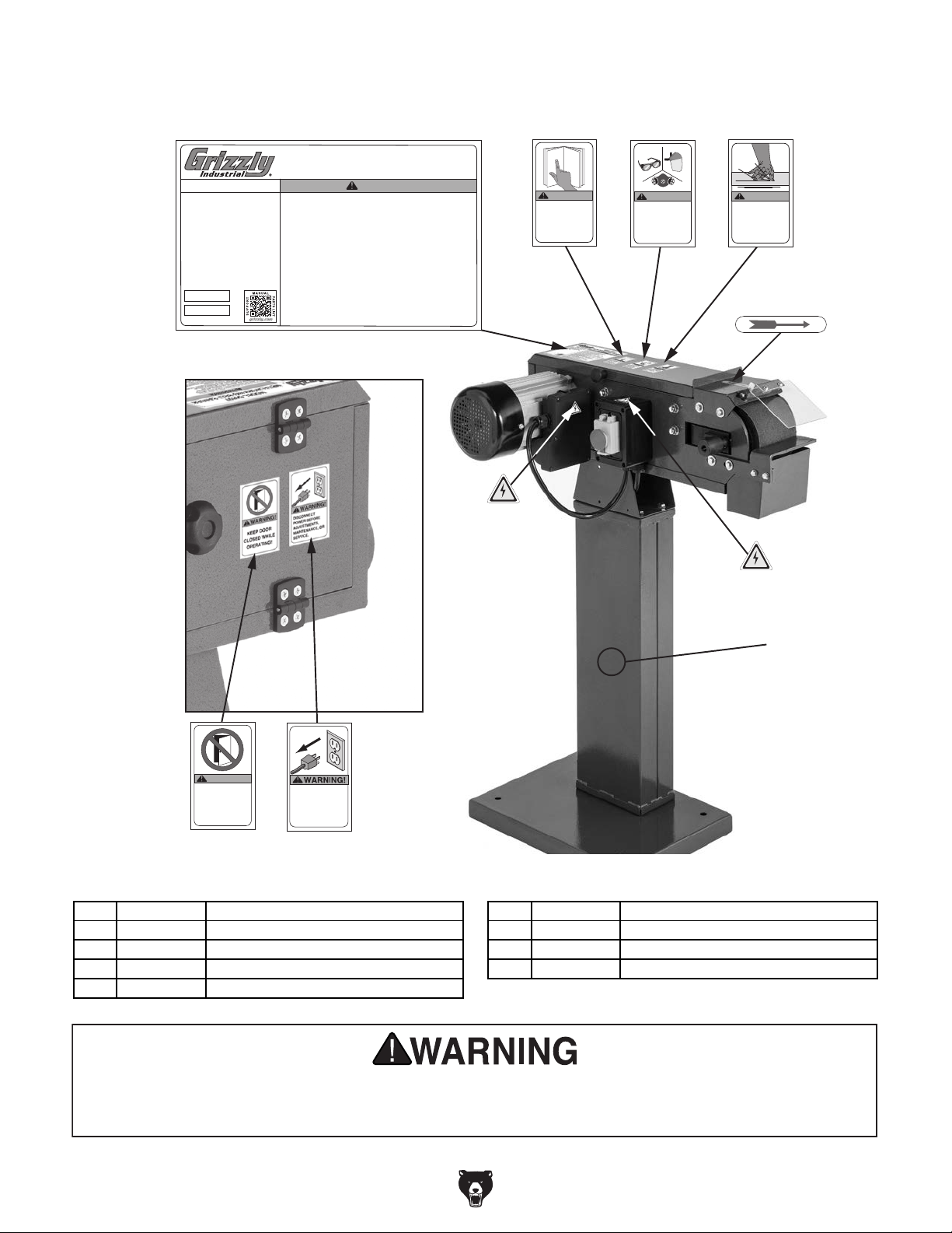
Labels & Cosmetics
102
103
104
105
106
101
Specifications
Motor: 2 HP, 110V, 1-Phase, 60 Hz
Full-Load Current Rating: 13.8A
Sanding Belt Size: 4" X 48"
Sanding Belt Speed: 4500 FPM
Platen Size: 4-3/4" X 11-1/8"
Weight: 75 lbs.
Date
S/N
Mfd. for Grizzly in China
2-WHEEL METAL BELT GRINDER
MODEL G0897
To reduce the risk of serious injury while using this machine:
1. Read and understand owner’s manual before operating.
2. Always wear approved eye protection and respirator.
3. Only plug power cord into a grounded outlet.
4. Support workpiece with a backstop or workrest.
5. Maintain 1/16" maximum clearance between rest and sandpaper.
6. Never touch moving sandpaper.
7. Always grind in accordance with directional arrows on machine.
8. Make sure grinder is properly assembled, adjusted, and stable before
operating. Only operate with all guards in place.
9. Never grind pointed stock with point facing into belt rotation, and never
force workpiece into grinding surface.
10. Only remove jammed pieces when sandpaper is stopped.
11. Turn motor OFF and disconnect power before changing sandpaper,
making adjustments, or servicing.
12. Do not wear loose clothing, gloves, jewelry, or other articles that can get
entangled. Tie back long hair and roll up sleeves.
13. Never reach over moving grinding belt.
14. Do not expose to rain or use in damp locations.
15. Do not operate under influence of drugs or alcohol, or when tired.
16. Prevent unauthorized use by children or untrained users; restrict
access or disable machine when unattended.
WARNING!
107
WARNING!
To reduce risk of death
or serious injury, read
manual BEFORE using
machine.
To get a new manual,
call (800) 523-4777 or
go to www.grizzly.com.
WARNING!
INJURY HAZARD!
Always wear ANSIapproved safety
glasses, face shield,
and respirator when
using this machine.
EYE/LUNG
WARNING!
ABRASION
INJURY HAZARD!
DO NOT touch moving
sanding belt or
personal injury may
occur!
108
109
WARNING!
KEEP DOOR
CLOSED WHILE
OPERATING!
DISCONNECT
POWER BEFORE
ADJUSTMENTS,
MAINTENANCE, OR
SERVICE.
REF PART # DES CRIPTIO N REF PART # DES CRIPTIO N
101 P0897101 MACHINE ID LABEL 106 P0897106 DISCONNECT POWER LABEL
102 P0897102 READ MANUAL LABEL 107 P0897107 ELECTRICITY LABEL
103 P0897103 EYE/ FACE/LUNG LABEL 108 P0897108 BELT DIRECTION LABEL
104 P0897104 ABRASION INJURY LABEL 109 P0897109 TO UCH-UP P AI NT, GRI ZZLY GREE N
105 P0897105 DON’T OPEN DOOR LABEL
Safety labels help reduce the risk of serious injury caused by machine hazards. If any label comes
off or becomes unreadable, the owner of this machine MUST replace it in the original location
before resuming operations. For replacements, contact (800) 523-4777 or www.grizzly.com.
-32-
Model G0897 (Mfd. Since 6/19)
Page 35

Grizzly Industrial, Inc. warrants every product it sells for a period of 1 year to the original purchaser from
the date of purchase. This warranty does not apply to defects due directly or indirectly to misuse, abuse,
negligence, accidents, repairs or alterations or lack of maintenance. This is Grizzly’s sole written warranty
and any and all warranties that may be implied by law, including any merchantability or fitness, for any particular purpose, are hereby limited to the duration of this written warranty. We do not warrant or represent
that the merchandise complies with the provisions of any law or acts unless the manufacturer so warrants.
In no event shall Grizzly’s liability under this warranty exceed the purchase price paid for the product and
any legal actions brought against Grizzly shall be tried in the State of Washington, County of Whatcom.
We shall in no event be liable for death, injuries to persons or property or for incidental, contingent, special,
or consequential damages arising from the use of our products.
The manufacturers reserve the right to change specifications at any time because they constantly strive to
achieve better quality equipment. We make every effort to ensure that our products meet high quality and
durability standards and we hope you never need to use this warranty.
In the event you need to use this warranty, contact us by mail or phone and give us all the details. We will
then issue you a “Return Number,’’ which must be clearly posted on the outside as well as the inside of
the carton. We will not accept any item back without this number. Proof of purchase must accompany the
merchandise.
Please feel free to write or call us if you have any questions about the machine or the manual.
Thank you again for your business and continued support. We hope to serve you again soon.
To
warranty-card
registration page
WARRANTY & RETURNS
take advantage of this warranty, you must register it at https://www.grizzly.com/secureforms/
, or you can scan the QR code below to be automatically directed to our warranty
. Enter all applicable information for the product.
WARRANTY
Page 36

 Loading...