

Page 1

READ THIS FIRST
Model G0887
***IMPORTANT UPDATE***
For Machines Mfd. Since 03/24
and Owner's Manual Printed 06/21
For questions or help with this product contact Tech Support at (570) 546-9663 or techsupport@grizzly.com
The following change was recently made since the owner's manual was printed:
• Power switch changed.
Aside from this information, all other content in the owner's manual applies and MUST be read and understood for your own safety. IMPORTANT: Keep this update with the owner's manual for future reference.
For questions or help, contact our Tech Support at (570) 546-9663 or techsupport@grizzly.com.
Revised Parts
3L2
1L1
Power Switch
Disconnector
NDS-203G5DL2-B
2T1
808V2 808V2
REF PART # DES CRIP TION
808V2 P0887808V2 POWER SWITCH ASSY NHD NDS-203G V2.03.24
NHD
4T2 6T3
5L3
ON
OFF
Power Switch
NHD NDS-203G5DL2-B
COPYRIGHT © MARCH, 2024 BY GRIZZLY INDUSTRIAL, INC.
WARNING: NO PORTION OF THIS MANUAL MAY BE REPRODUCED IN ANY SHAPE
OR FORM WITHOUT THE WRITTEN APPROVAL OF GRIZZLY INDUSTRIAL, INC.
#LW23140 PRINTED IN TAIWAN
Page 2

READ THIS FIRST
Model G0887
***IMPORTANT UPDATE***
For Machines Mfd. Since 05/23
and Owner's Manual Printed 06/21
For questions or help with this product contact Tech Support at (570) 546-9663 or techsupport@grizzly.com
The following changes were recently made since the owner's manual was printed:
• Variable Frequency Drive has changed.
• Electrical Cabinet Wiring Diagram has changed.
• Electrical Cabinet Parts Diagram has changed.
Aside from this information, all other content in the owner's manual applies and MUST be read and understood for your own safety. IMPORTANT: Keep this update with the owner's manual for future reference.
For questions or help, contact our Tech Support at (570) 546-9663 or techsupport@grizzly.com.
Old VFD New VFD
COPYRIGHT © JUNE, 2023 BY GRIZZLY INDUSTRIAL, INC.
WARNING: NO PORTION OF THIS MANUAL MAY BE REPRODUCED IN ANY SHAPE
OR FORM WITHOUT THE WRITTEN APPROVAL OF GRIZZLY INDUSTRIAL, INC.
#JP22776 PRINTED IN TAIWAN
Page 3

ELECTRICAL CABINET
(Replaces Page 81 in Manual)
Electrical Cabinet Wiring Diagram
R12
S12
3L2
1L1
Power Switch
Disconnector
ABB OT25F3
2T1
L1 L3L2
RST
T12
4T2 6T3
R1
R12
5L3
S1
S12
L1
L4
Circuit Board
RF500M 0904
0 220 0 24 0 12
0V 0V
L6
Transformer
LCE LCPIC-TBSW-100250
0V
30
29
28
27
17
16
15
L5
31
15G
See Page 82
0V
RUN-LAMP
COUNTER
220V
32
DOWN
UP
CLOSE
OPEN
+12
EMER-SW
OV
PUMP-EV
WATER-EV
MOTOR-EV
OV
UB 2
GND
UB 1
GND
AUTO-STOP
GND
BROKE-SW
GND
SAFE-SW
GND
LS-DOWN
GND
LS-CLIP
GND
PUMP
WATERMOTOR
L1
L3
L1
3L2
1L1
13NO
A1
5L3
Contactor
NHD C-06D10
1L1
3L2
5L3
Contactor
NHD C-06D10
13NO
31
29
4T2 6T3
2T1
OL Relay
TECO RHU-10/1K1
TRIP IND.
14
TEST
12
98 NO
97 NO
2T1
4T2
U2
A2
14NO
30
16
A
M
R
O
A
11.3
16
RESET
OFF
95 NC
96 NC
6T3
U1
W2
4T2 6T3
2T1
OL Relay
TECO RHU-10/1K1
TRIP IND.
14
TEST
12
98 NO
97 NO
2T1
4T2
V1
14NO
32
16
A
M
R
O
A
11.3
RESET
OFF
95 NC
96 NC
15G
6T3
17
W1
V2
15G
15G
L3
L4
L1
T1
U3
A1
A2
U3
V3
W3
V3
L1
1L1 3L2
TECO CU-18
2T1
OL Relay
TECO RHU-10/16K1
TRIP IND.
TEST
97 NO
2T1
L3
L2
A1
Contactor
14
4T2 6T3
16
A
12
11.3
98 NO
15G
4T2
L6
A2
5L3
27
13NO
21NC
28
22NC
14NO
M
R
O
A
RESET
OFF
95 NC
96 NC
6T3
W3
W2
U2 W1
U1
V2
L5
24V
12V
15
W1
V1
WVU
U1
V1
See Page 82
W3U3
W2
U2
V3
W1V1U1
WVU
V2
MCMSGNDSG-SG+DCMS2S1+24V
Variable Frequency Drive
DELTA VFD4A8MS23ANSAA
Control
RST
Hot
Panel
See
Page 85
Hot
Hot
Ground
220 VAC
L15-30 PLUG
(As Recommended)
RA RB RC
MO2MO1AFMACIAV IAC M+10V
To
DFMDCMDCM+24V+24V
MI7MI6MI5
MI4
MI3
R/L1 S/L2 T/L3 U/T1 V/T2 W/T3
MI2
MI1
Page 88
W4
V4
U4
To
Table
Motor
See
W1
V1
U1
Page 87
To
Blade
Brush
Motor
See
To
Hydraulic
Motor
See
Page 87
To Control Panel
See Page 85
To
Coolant
Pump
Motor
See
Page 87
To
Main
Motor
See
Page 86
-2-
READ ELECTRICAL SAFETY
ON PAGE 78!
G0887 Update (Mfd. Since 05/23)
Page 4

(Replaces Page 83 in Manual)
Figure 122. Electrical cabinet components and wiring connections.
G0887 Update (Mfd. Since 05/23)
READ ELECTRICAL SAFETY
ON PAGE 78!
-3-
Page 5

(Replaces Page 102 in Manual)
804
Electrical Cabinet
ELECTRICAL CABINET
801
803
805
807
815
816
806
817
818
819
3L2
1L1
5L3
807
Power Switch
Disconnector
ABB OT25F3
4T2 6T3
2T1
805
808
802
823
824
Variable Frequency Drive
DELTA VFD4A8MS23ANSAA
807
820
820
809
2T1
TECO RHU-10/1K1
TRIP IND.
TEST
810
1L1
OL Relay
97 NO
2T1
821
3L2
5L3
Contactor
NHD C-06D10
4T2 6T3
16
A
14
12
11.3
95 NC
98 NO
4T2
822
809
1L1
13NO
A1
A2
14NO
2T1
OL Relay
TECO RHU-10/1K1
TRIP IND.
M
R
O
A
TEST
RESET
OFF
97 NO
96 NC
2T1
6T3
833
825V2
811
3L2
13NO
A1
5L3
Contactor
NHD C-06D10
4T2 6T3
16
A
14
12
11.3
95 NC
98 NO
4T2
14NO
M
R
O
A
RESET
OFF
96 NC
6T3
1L1 3L2
2T1
A2
TECO RHU-10/16K1
TRIP IND.
TEST
97 NO
Contactor
TECO CU-18
4T2 6T3
OL Relay
16
14
12
98 NO
2T1
4T2
5L3
13NO
21NC
22NC
14NO
A
R
O
11.3
RESET
OFF
95 NC
96 NC
6T3
812
818 818 818
819 819 819 819
802
807
Transformer
LCE LCPIC-TBSW-100250
805
827
828
829
830
814
813
M
A
Circuit Board
RF500M 0904
RUN-LAMP
COUNTER
220V
PUMP
WATERMOTOR
DOWN
UP
CLOSE
OPEN
818
+12
EMER-SW
OV
PUMP-EV
WATER-EV
MOTOR-EV
OV
UB 2
GND
UB 1
GND
AUTO-STOP
GND
BROKE-SW
GND
SAFE-SW
GND
LS-DOWN
GND
LS-CLIP
GND
-4-
831
832
BUY PARTS ON LINE AT GRI ZZLY.COM!
Scan QR c ode to vi sit ou r Part s Store .
808
1
0
Power Switch
ABB YJ1/120
G0887 Update (Mfd. Since 05/23)
Page 6

(Replaces Page 103 in Manual)
816 P0887816 PHLP HD SCR 1/4-20 X 3/ 8 833 P0887833 OL RELAY TECO RHU-10/1K1 5. 5-7.5A
Electrical Cabinet Parts List
REF PART # DES CRIPTI ON REF PART # DES CRIPTI ON
801 P0887801 WIRING LOOM 1-1/ 4 X 1-3/ 4 X 14" 817 P0887817 GROUND TERMINAL 16-POLE 1-PIECE
802 P0887802 WIRING LOOM 1-1/ 4 X 1-3/ 4 X 13" 818 P0887818 TERMINAL BAR 1P
803 P0887803 WIRING LOOM 1-3/ 4 X 1-3/ 4 X 20-1/2" 819 P0887819 TERMINAL BAR 3P
804 P0887804 WIRING LOOM 1 X 1-3/ 4 X 13" 820 P0887820 TERMINAL BAR 2P
805 P0887805 DIN RAI L 1-3/ 8 X 3/8 X 12" 821 P0887821 TERMINAL BAR 1P
806 P0887806 DIN RAI L 1-3/ 8 X 3/8 X 12" 822 P0887822 TERMINAL BAR 16P
807 P0887807 DI N RA I L END CA P 823 P0887823 FUSE HOLDER WOHNER AES 10 X 38
808 P0887808 POWER SWITCH ASSY ABB 0T25F3/ YJ1/20 824 P0887824 FUSE 32A 250V CERAMI C 0.36"
809 P0887809 CONTA CTO R NHD C-0 6D10 24 V 825V2 P0887825V2 VFD DELTA VFD4A8MS23ANSAA V2. 05.23
810 P0887810 OL RELAY TECO RHU-10/1K1 0.75-1A 827 P0887827 PHLP HD SCR M5-.8 X 10
811 P0887811 CONTA CTO R TECO CU-18 24 V 828 P0887828 TRANSFORMER 250VA 0/250V-24/ 200V
812 P0887812 OL RELAY TECO RHU-10/16K1 11.3-16A 829 P0887829 CI RCUI T B OA RD RF500 M 090 4
813 P0887813 FUSE HOLDER 830 P0887830 PHLP HD SCR M3-.5 X 8
814 P0887814 FUSE 5A 250V CERAMIC 0.18" 831 P0887831 STRAI N RELIEF TYPE-3 1
815 P0887815 PHLP HD SCR M4-.7 X 15 832 P0887832 POWER CORD 10G 4W 120" L15-30
G0887 Update (Mfd. Since 05/23)
BUY PARTS ON LINE AT GRI ZZLY.COM!
Scan QR c ode to vi sit ou r Part s Store .
-5-
Page 7

-6-
READ ELECTRICAL SAFETY
ON PAGE 78!
G0887 Update (Mfd. Since 05/23)
Page 8

MODEL G0887
20" X 26" 5 HP INDUSTRIAL
METAL-CUTTING BANDSAW
OWNER'S MANUAL
(For models manufactured since 01/19)
COPYRIGHT © JUNE, 2021 BY GRIZZLY INDUSTRIAL, INC.
WARNING : NO PORTION OF THIS MANUAL MAY BE REPRODUCED IN ANY SHAPE
OR FORM WITHOUT THE WRITTEN APPROVAL OF GRIZZLY INDUSTRIAL, INC.
#CS20972 PRINTED IN TAIWA N
V1.06.21
Page 9

This manual provides critical safety instructions on the proper setup,
operation, maintenance, and service of this machine/tool. Save this
document, refer to it often, and use it to instruct other operators.
Failure to read, understand and follow the instructions in this manual
may result in fire or serious personal injury—including amputation,
electrocution, or death.
The owner of this machine/tool is solely responsible for its safe use.
This responsibility includes but is not limited to proper installation in
a safe environment, personnel training and usage authorization,
proper inspection and maintenance, manual availability and comprehension, application of safety devices, cutting/sanding/grinding tool
integrity, and the usage of personal protective equipment.
The manufacturer will not be held liable for injury or property damage
from negligence, improper training, machine modifications or misuse.
Some dust created by power sanding, sawing, grinding, drilling, and
other construction activities contains chemicals known to the State
of California to cause cancer, birth defects or other reproductive
harm. Some examples of these chemicals are:
• Lead from lead-based paints.
• Crystalline silica from bricks, cement and other masonry products.
• Arsenic and chromium from chemically-treated lumber.
Your risk from these exposures varies, depending on how often you
do this type of work. To reduce your exposure to these chemicals:
Work in a well ventilated area, and work with approved safety equipment, such as those dust masks that are specially designed to filter
out microscopic particles.
Page 10

Table of Contents
INTRODUCTION ............................................... 2
Contact Info.................................................... 2
Manual Accuracy
Identification
Controls & Components
Machine Data Sheet
SECTION 1: SAFETY
Safety Instructions for Machinery
Additional Safety for Horizontal Metal
Bandsaws
Additional Safety for Hydraulic Systems
SECTION 2: POWER SUPPLY
SECTION 3: SETUP
Needed for Setup
Unpacking
Inventory
Hardware Recognition Chart
Cleanup
Site Considerations
Assembly
Power Connection........................................ 22
Test Run
Recommended Adjustments
SECTION 4: OPERATIONS
Operation Overview
Disabling Switch........................................... 27
Operation Tips
Workpiece Inspection................................... 28
Selecting Blades
Blade Breakage
Blade Care & Break-In
Setting Blade Feed Rate.............................. 31
Changing Blade Speed
Blade Speed Chart
Chip Inspection Chart
Changing Blade
Tensioning Blade
Adjusting Blade Guides
Adjusting Blade Guard Extension
Manual & Automatic Controls
Identifying Failures
Setting Headstock Height
Setting Headstock Angle
Using Vise
Adjusting Support Vise Guide
Adjusting Work Stop
Using Coolant System
.................................................... 11
.................................................... 15
...................................................... 16
........................................................ 18
..................................................... 20
...................................................... 23
.................................................... 42
........................................... 2
................................................... 3
................................. 4
...................................... 6
....................................... 9
.................. 9
...... 12
...................... 13
....................................... 15
......................................... 15
....................... 17
...................................... 19
........................ 25
........................... 26
..................................... 26
............................................. 27
.......................................... 28
........................................... 30
................................. 30
................................ 31
...................................... 32
.................................. 33
........................................... 34
......................................... 36
............................... 37
................ 38
...................... 39
....................................... 40
............................ 40
............................. 41
...................... 44
.................................... 44
................................. 45
SECTION 5: ACCESSORIES
SECTION 6: MAINTENANCE
Schedule
Cleaning & Protecting
Lubrication
Hydraulic System
Coolant System Maintenance
Inspecting Drive Belt
Storing Machine
SECTION 7: SERVICE
Troubleshooting
Adjusting Blade Brush
Adjusting Blade Guides & Bearings
Adjusting Blade Tracking
Squaring Blade to Table
Adjusting Blade Tension Limit Switch
Adjusting Downfeed Stop Bolt
Adjusting Headstock Spring
Replacing/Tensioning Drive Belt
SECTION 8: HYDRAULICS
Hydraulic System Schematic
Hydraulic System Diagram
SECTION 9: WIRING
Wiring Safety Instructions
Component Locations
Electrical Overview
Electrical Cabinet Wiring Diagram
Hydraulic System Wiring Diagram
Control Panel Wiring Diagram
Motor Wiring Diagrams
Other Electrical Component Wiring
Diagrams
SECTION 10: PARTS
Headstock
Table & Vise
Base & Accessories
Hydraulic Pump............................................ 98
Blade Guides & Support Vise
Coolant System.......................................... 100
Control Panel & Electrical Components
Electrical Cabinet
Labels & Cosmetics
WARRANTY & RETURNS
...................................................... 49
................................................... 50
......................................... 53
.................................... 58
........................................... 59
................................... 60
........................................... 60
...................................... 78
...................................... 80
...................................................... 88
..................................... 90
.................................................... 90
................................................ 93
..................................... 96
....................................... 102
................................... 104
......................... 47
......................... 49
.................................. 49
...................... 56
................................. 65
............. 66
............................. 68
.............................. 70
.......... 71
..................... 72
......................... 73
.................. 74
............................ 76
....................... 76
.......................... 77
............................ 78
.................................. 79
............... 81
............... 84
..................... 85
................................ 86
...................... 99
.... 101
........................... 105
Page 11

We stand behind our machines! If you have questions or need help, contact us with the information
below. Before contacting, make sure you get the
serial number
machine ID label. This will help us help you faster.
We want your feedback on this manual. What did
you like about it? Where could it be improved?
Please take a few minutes to give us feedback.
Email: manuals@grizzly.com
We are proud to provide a high-quality owner’s
manual with your new machine!
We
instructions, specifications, drawings, and photographs
in this manual. Sometimes we make mistakes, but
our policy of continuous improvement also means
that
you receive is
slightly different than shown in the manual
If you find this to be the case, and the difference
between the manual and machine leaves you
confused or unsure about something
check our
website for an updated version. W
current
manuals and
on our web-
site at
Alternatively, you can call our Technical Support
for help. Before calling, make sure you write
down the
serial number
from the machine ID label (see below). This
information is required for us to provide proper
tech support, and it helps us determine if updated
documentation is available for your machine.
INTRODUCTION
Contact Info
and manufacture date from the
Grizzly Technical Support
1815 W. Battlefield
Springfield, MO 65807
Phone: (570) 546-9663
Email: techsupport@grizzly.com
Grizzly Documentation Manager
P.O. Box 2069
Bellingham, WA 98227-2069
Manual Accuracy
made every effort to be exact with the
sometimes the machine
.
,
e post
manual updates for free
www.grizzly.com.
manufacture date and
Manufacture Date
Serial Number
-2-
Model G0887 (Mfd. Since 01/19)
Page 12

Identification
To reduce your risk of
serious injury, read this
entire manual BEFORE
Become familiar with the names and locations of the controls and features shown below to better understand
the instructions in this manual.
Front View
Blade Guide
Scale
Blade
Tension
Handwheel
w/Gauge
Main Power
ON/OFF
Switch
Electrical
Cabinet
Rear View
Blade Speed
Dial
Support
Vise
Control
Panel
Blade Guide
Arm (1 of 2)
Workpiece
Stop
Cutoff Chute
Headstock
Blade Speed Display
Coolant Valve
(1 of 3)
Model G0887 (Mfd. Since 01/19)
Vise Lock
Handle
Movable
Vise Jaw
Fixed
Vise Jaw
using machine.
-3-
Page 13

Controls &
To reduce your risk of
serious injury, read this
entire manual BEFORE
Components
Vise Table
G
H
using machine.
Refer to the following figures and descriptions to
become familiar with the basic controls and components of this machine. Understanding these
items and how they work will help you understand
the rest of the manual and minimize your risk of
injury when operating this machine.
Headstock
A
B
C
F
Figure 1. Headstock controls and components.
A. Blade Tension Handwheel w/Gauge:
Increases or decreases blade tension. Gauge
ensures accurate tensioning of blade.
D
E
Figure 2. Vise table controls and components.
G. Movable Vise Jaw: Holds workpiece against
fixed vise jaw during cutting operations.
H. Vise Lock Handle: Loosen to adjust vise or
tighten to secure its position.
Blade Speed
I
Figure 3. Blade speed dial.
I. Blade Speed Dial: Controls blade speed.
Rotate knob clockwise to decrease speed or
counterclockwise to increase speed.
Electrical Box
B. Blade Guide Scale: Displays position of left
blade guide arm relative to workpiece.
Blade Guide Arms: Hold guides that support
C.
blade. Adjust left arm as close to workpiece
as possible to prevent blade from twisting.
D. Coolant Valves (1 of 3): Control flow of cool-
ant through blade guides and onto blade.
E. Work Stop: Provides outfeed scale for repet-
itive cutting operations.
F. Support Vise: Adjusts to provide outfeed
workpiece support.
-4-
J
Figure 4. Electrical cabinet power switch.
J. Master Power ON/OFF Switch: Turns
incoming power ON and OFF.
Model G0887 (Mfd. Since 01/19)
Page 14

Control Panel
K
L
AD
AC
K. Emergency Stop Button: Stops all machine
functions. Twist clockwise to reset.
L. Blade Feed Rate Dial: Controls rate at which
blade feeds into workpiece.
M. Auto Cycle Start Button : Starts automat-
ic cutting cycle. Coolant pump starts, blade
starts, headstock cuts down into workpiece,
saw blade stops, headstock raises, and vise
opens to release workpiece.
N. Cut Counter: The number of completed cuts
is displayed. Push tab to clear.
O. Headstock Angle Joystick: Manually con-
trols angle of headstock after target angle
has been set.
P. Headstock Digital Readout: Displays angle
and height of headstock.
Q. Headstock Increase/Decrease Buttons:
Adjusts headstock height or angle setting
up/down.
R. Height Limit Button : Enters height limit
entry mode to edit maximum headstock
height.
AB
Figure 5. Control panel functions.
O
N
M
Z
AA
X
Y
U. Motor Stop Button : Turns all motors OFF.
Blade Start/Stop Button : Starts and stops
V.
saw blade and blade brush. IMPORTANT:
For button to start blade, hydraulic start button and vise close button must be pressed
first, and headstock raised.
Hydraulic Start/Stop Button : Turns
W.
hydraulic motor ON and OFF.
X. Headstock Height Controls / : Adjusts
height of headstock while in manual mode.
Vise Controls / : Hydraulically opens
Y.
and closes workpiece vise.
Z. Manual Operation Button : Selects man-
ual operation mode.
AA. Auto Operation Button : Selects Auto
operation mode.
AB. Failure Indicator: Illuminates to display
where on machine a setting requires operator
intervention.
AC. Power Indicator: Illuminates when machine
is connected to power.
P
Q
R
V
W
S
T
U
S. Angle Control Button : Enters angle
entry mode to edit headstock angle.
T. Coolant Pump Button : Turns coolant
pump ON and OFF.
Model G0887 (Mfd. Since 01/19)
AD. Master Power ON/OFF Key Switch: Turns
incoming power ON and OFF when key is
inserted.
-5-
Page 15

Machine Data Sheet
MACHINE DATA
SHEET
Customer Service #: (570) 546-9663 · To Order Call: (800) 523-4777 · Fax #: (800) 438-5901
MODEL G0887 20" X 26" 5 HP INDUSTRIAL METAL‐
CUTTING BANDSAW
Product Dimensions:
Weight............................................................................................................................................................ 3747 lbs.
Width (side-to-side) x Depth (front-to-back) x Height......................................................................... 119 x 63 x 70 in.
Footprint (Length x Width)............................................................................................................................ 77 x 36 in.
Shipping Dimensions:
Type.......................................................................................................................................................... Wood Crate
Content........................................................................................................................................................... Machine
Weight............................................................................................................................................................ 3960 lbs.
Length x Width x Height..................................................................................................................... 120 x 55 x 79 in.
Must Ship Upright................................................................................................................................................... Yes
Electrical:
Power Requirement................................................................................................................... 220V, 3-Phase, 60 Hz
Full-Load Current Rating........................................................................................................................................ 25A
Minimum Circuit Size.............................................................................................................................................. 30A
Connection Type................................................................................................................................ Cord Connected
Power Cord Included.............................................................................................................................................. Yes
Power Cord Length............................................................................................................................................... 12 ft.
Power Cord Gauge......................................................................................................................................... 10 AWG
Plug Included........................................................................................................................................................... No
Recommended Plug Type................................................................................................... L15-30 (Grizzly #T24832)
Switch Type.............................................................................................................. Control Panel w/Magnetic Switch
Recommended Phase Converter.......................................................................................................... G7978, H3473
Motors:
Main
Hydraulic Pump
Horsepower................................................................................................................................................ 5 HP
Phase.................................................................................................................................................... 3-Phase
Amps......................................................................................................................................................... 15.2A
Speed................................................................................................................................................ 1728 RPM
Type........................................................................................................................................... TEFC Induction
Power Transfer ........................................................................................................................................ V-Belt
Bearings........................................................................................................ Sealed & Permanently Lubricated
Horsepower................................................................................................................................................ 2 HP
Phase.................................................................................................................................................... 3-Phase
Amps........................................................................................................................................................... 5.7A
Speed................................................................................................................................................ 1720 RPM
Type........................................................................................................................................... TEFC Induction
Power Transfer ......................................................................................................................................... Direct
Bearings........................................................................................................ Sealed & Permanently Lubricated
-6-
Model G0887 (Mfd. Since 01/19)
Page 16

Table
Horsepower................................................................................................................................................ 1 HP
Phase.................................................................................................................................................... 3-Phase
Amps......................................................................................................................................................... 3.28A
Speed................................................................................................................................................ 1680 RPM
Type........................................................................................................................................... TEFC Induction
Power Transfer ......................................................................................................................................... Direct
Bearings........................................................................................................ Sealed & Permanently Lubricated
Coolant Pump
Horsepower............................................................................................................................................. 1/8 HP
Phase.................................................................................................................................................... 3-Phase
Amps......................................................................................................................................................... 0.26A
Speed................................................................................................................................................ 3440 RPM
Type..................................................................................................................................................... Universal
Power Transfer ......................................................................................................................................... Direct
Bearings........................................................................................................ Sealed & Permanently Lubricated
Blade Brush
Horsepower................................................................................................................................................. 60W
Phase.................................................................................................................................................... 3-Phase
Amps......................................................................................................................................................... 0.41A
Speed................................................................................................................................................ 1600 RPM
Type........................................................................................................................................... TEFC Induction
Power Transfer ......................................................................................................................................... Direct
Bearings........................................................................................................ Sealed & Permanently Lubricated
Main Specifications:
Operation Info
Blade Speeds............................................................................................................................. 106 - 315 FPM
Std. Blade Length.................................................................................................................................... 232 in.
Blade Length Range.......................................................................................................... 231-1/2 - 232-1/4 in.
Std. Blade Width.................................................................................................................................... 1-1/2 in.
Cutting Capacities
Cutting Height............................................................................................................................................ 20 in.
Angle Cuts.................................................................................................................................... 0-60 deg. R/L
Vise Jaw Depth.................................................................................................................................... 11-3/4 in.
Vise Jaw Height................................................................................................................................... 10-1/4 in.
Max. Capacity Rectangular Height at 90 Deg............................................................................................ 20 in.
Max. Capacity Rectangular Width at 90 Deg....................................................................................... 25-7/8 in.
Max. Capacity Round at 90 Deg................................................................................................................ 20 in.
Max. Capacity Rectangular Height at 30 Deg............................................................................................ 20 in.
Max. Capacity Rectangular Width at 30 Deg....................................................................................... 23-5/8 in.
Max. Capacity Round at 30 Deg................................................................................................................ 20 in.
Max. Capacity Rectangular Height at 45 Deg............................................................................................ 20 in.
Max. Capacity Rectangular Width at 45 Deg............................................................................................. 20 in.
Max. Capacity Round at 45 Deg................................................................................................................ 20 in.
Max. Capacity Rectangular Height at 60 Deg............................................................................................ 14 in.
Max. Capacity Rectangular Width at 60 Deg............................................................................................. 14 in.
Max. Capacity Round at 60 Deg.......................................................................................................... 14-7/8 in.
Max. Capacity Rectangular Height at -45 Deg.......................................................................................... 20 in.
Max. Capacity Rectangular Width at -45 Deg............................................................................................ 20 in.
Max. Capacity Round at -45 Deg............................................................................................................... 20 in.
Model G0887 (Mfd. Since 01/19)
-7-
Page 17

Construction
Table....................................................................................................................... Precision-Ground Cast Iron
Upper Wheel........................................................................................................................................ Cast Iron
Lower Wheel........................................................................................................................................ Cast Iron
Body........................................................................................................................................................... Steel
Stand.......................................................................................................................................................... Steel
Wheel Cover............................................................................................................................................... Steel
Paint Type/Finish...................................................................................................................................... Epoxy
Other
Wheel Size.......................................................................................................................................... 23-5/8 in.
Blade Guides......................................................................................................... Carbide Steel, Ball Bearings
Coolant Capacity..................................................................................................................................... 10 gal.
Hydraulic Capacity..................................................................................................................................... 30 qt.
Other Specifications:
Country of Origin .............................................................................................................................................. Taiwan
Warranty ........................................................................................................................................................... 1 Year
Approximate Assembly & Setup Time .............................................................................................................. 1 Hour
Serial Number Location ................................................................................................................... Machine ID Label
ISO 9001 Factory .................................................................................................................................................. Yes
Features:
20" H x 25-7/8" L Cutting Capacity
Cuts 0-60 Deg. Left or Right
Hydraulic Headstock Lifting, Vise Clamping, and Angle Adjustment
Automatic Headstock Lifting w/Programmable Height Stop
Blade Tension Meter
Sliding Vise w/Material Outfeed Support
106 - 315 FPM Variable-Speed Blade Control
10-Gallon Coolant Tank
Coolant Hose w/Spray Nozzle
-8-
Model G0887 (Mfd. Since 01/19)
Page 18

SECTION 1: SAFETY
For Your Own Safety, Read Instruction
Manual Before Operating This Machine
The purpose of safety symbols is to attract your attention to possible hazardous conditions.
This manual uses a series of symbols and signal words intended to convey the level of importance of the safety messages. The progression of symbols is described below. Remember that
safety messages by themselves do not eliminate danger and are not a substitute for proper
accident prevention measures. Always use common sense and good judgment.
Indicates an imminently hazardous situation which, if not avoided,
WILL result in death or serious injury.
Indicates a potentially hazardous situation which, if not avoided,
COULD result in death or serious injury.
Indicates a potentially hazardous situation which, if not avoided,
MAY result in minor or moderate injury. It may also be used to alert
against unsafe practices.
Alerts the user to useful information about proper operation of the
NOTICE
machine to avoid machine damage.
Safety Instructions for Machinery
OWNER’S MANUAL. Read and understand this
owner’s manual BEFORE using machine.
TRAINED OPERATORS ONLY. Untrained operators have a higher risk of being hurt or killed.
Only allow trained/supervised people to use this
machine. When machine is not being used, disconnect power, remove switch keys, or lock-out
machine to prevent unauthorized use—especially
around children. Make your workshop kid proof!
DANGEROUS ENVIRONMENTS. Do not use
machinery in areas that are wet, cluttered, or have
poor lighting. Operating machinery in these areas
greatly increases the risk of accidents and injury.
MENTAL ALERTNESS REQUIRED. Full mental
alertness is required for safe operation of machinery. Never operate under the influence of drugs or
alcohol, when tired, or when distracted.
ELECTRICAL EQUIPMENT INJURY RISKS.
You can be shocked, burned, or killed by touching
live electrical components or improperly grounded
machinery. To reduce this risk, only allow qualified
service personnel to do electrical installation or
repair work, and always disconnect power before
accessing or exposing electrical equipment.
DISCONNECT POWER FIRST.
nect machine from power supply BEFORE making adjustments, changing tooling, or servicing
machine. This prevents an injury risk from unintended startup or contact with live electrical components.
EYE PROTECTION. Always wear ANSI-approved
safety glasses or a face shield when operating or
observing machinery to reduce the risk of eye
injury or blindness from flying particles. Everyday
eyeglasses are NOT approved safety glasses.
Always discon-
Model G0887 (Mfd. Since 01/19)
-9-
Page 19

WEARING PROPER APPAREL. Do not wear
clothing, apparel or jewelry that can become
entangled in moving parts. Always tie back or
cover long hair. Wear non-slip footwear to reduce
risk of slipping and losing control or accidentally
contacting cutting tool or moving parts.
HAZARDOUS DUST. Dust created by machinery
operations may cause cancer, birth defects, or
long-term respiratory damage. Be aware of dust
hazards associated with each workpiece material. Always wear a NIOSH-approved respirator to
reduce your risk.
HEARING PROTECTION. Always wear hearing protection when operating or observing loud
machinery. Extended exposure to this noise
without hearing protection can cause permanent
hearing loss.
REMOVE ADJUSTING TOOLS. Tools left on
machinery can become dangerous projectiles
upon startup. Never leave chuck keys, wrenches,
or any other tools on machine. Always verify
removal before starting!
USE CORRECT TOOL FOR THE JOB. Only use
this tool for its intended purpose—do not force
it or an attachment to do a job for which it was
not designed. Never make unapproved modifications—modifying tool or using it differently than
intended may result in malfunction or mechanical
failure that can lead to personal injury or death!
AWKWARD POSITIONS. Keep proper footing
and balance at all times when operating machine.
Do not overreach! Avoid awkward hand positions
that make workpiece control difficult or increase
the risk of accidental injury.
CHILDREN & BYSTANDERS. Keep children and
bystanders at a safe distance from the work area.
Stop using machine if they become a distraction.
GUARDS & COVERS. Guards and covers reduce
accidental contact with moving parts or flying
debris. Make sure they are properly installed,
undamaged, and working correctly BEFORE
operating machine.
FORCING MACHINERY. Do not force machine.
It will do the job safer and better at the rate for
which it was designed.
NEVER STAND ON MACHINE. Serious injury
may occur if machine is tipped or if the cutting
tool is unintentionally contacted.
STABLE MACHINE. Unexpected movement during operation greatly increases risk of injury or
loss of control. Before starting, verify machine is
stable and mobile base (if used) is locked.
USE RECOMMENDED ACCESSORIES. Consult
this owner’s manual or the manufacturer for recommended accessories. Using improper accessories will increase the risk of serious injury.
UNATTENDED OPERATION. To reduce the
risk of accidental injury, turn machine OFF and
ensure all moving parts completely stop before
walking away. Never leave machine running
while unattended.
MAINTAIN WITH CARE. Follow all maintenance
instructions and lubrication schedules to keep
machine in good working condition. A machine
that is improperly maintained could malfunction,
leading to serious personal injury or death.
DAMAGED PARTS. Regularly inspect machine
for damaged, loose, or mis-adjusted parts—or
any condition that could affect safe operation.
Immediately repair/replace BEFORE operating
machine. For your own safety, DO NOT operate
machine with damaged parts!
MAINTAIN POWER CORDS. When disconnecting cord-connected machines from power, grab
and pull the plug—NOT the cord. Pulling the cord
may damage the wires inside. Do not handle
cord/plug with wet hands. Avoid cord damage by
keeping it away from heated surfaces, high traffic
areas, harsh chemicals, and wet/damp locations.
EXPERIENCING DIFFICULTIES. If at any time
you experience difficulties performing the intended operation, stop using the machine! Contact our
Technical Support at (570) 546-9663.
-10 -
Model G0887 (Mfd. Since 01/19)
Page 20

Additional Safety for
Horizontal Metal Bandsaws
Serious injury or death can occur from getting fingers, hair, or clothing entangled in rotating or
moving parts or making direct contact with the moving blade. To minimize risk of injury, anyone
operating this machine MUST completely heed hazards and warnings below.
BLADE CONDITION. Do not operate with dull,
cracked, or badly worn blade. Inspect blades for
cracks and missing teeth before each use.
HAND PLACEMENT. Never position hands or fingers in line with the cut or under bandsaw headstock while lowering or operating. Hands could be
cut or crushed.
BLADE GUARD POSITION. Adjust blade guard
as close to workpiece as possible before cutting
to minimize operator exposure to unused portion
of blade.
ENTANGLEMENT HAZARDS. Do not operate
this saw without blade guard in place. Loose
clothing, jewelry, long hair and work gloves can be
drawn into working parts.
BLADE REPLACEMENT. When replacing
blades, disconnect the machine from power, wear
gloves to protect hands and safety glasses to
protect eyes.
HOT SURFACES. Contact with hot surfaces from
machine components, ejections of hot chips,
swarf, and the workpiece itself can cause burns.
WORKPIECE HANDLING. Always properly support workpiece with table, vise, or some type of
support fixture. Always secure workpiece in vise
before cutting. Never hold the workpiece with your
hands during a cut.
UNSTABLE WORKPIECES. Avoid cutting workpieces that cannot be properly supported or
clamped in a vise or jig, because they can unexpectedly move while cutting and draw the operator’s hands into the blade causing serious personal injury. Examples are chains, cables, round
or oblong-shaped workpieces, and those with
internal or built-in moving or rotating parts, etc.
FIRE HAZARD. Use EXTREME CAUTION if cutting magnesium. Using the wrong cutting fluid
could lead to chip fire and possible explosion.
CUTTING FLUID SAFETY. Cutting fluids are
poisonous. Always follow manufacturer’s cuttingfluid safety instructions. Pay particular attention
to contact, contamination, inhalation, storage and
disposal warnings. Spilled cutting fluid invites slipping hazards.
Model G0887 (Mfd. Since 01/19)
-11-
Page 21

Additional Safety for Hydraulic Systems
Infection, amputation, or death can result from contact with leaking hydraulic fluid under high
pressure. Additionally, leaking hydraulic fluid is a serious slip hazard and fire hazard. To reduce
these risks, anyone operating this machine MUST completely heed the hazards and warnings
below.
INJECTION INJURIES. Immediately seek medi-
cal attention if injection injury occurs. Leaking
hydraulic fluid often has enough pressure to penetrate skin, which can lead to infection, amputation, or death. Hydraulic fluid can enter the skin
through small wounds that are barely noticeable.
Minimizing the time between injury and removal
of the injected material is critical to successful
treatment.
CHECK FOR LEAKS. Never use your hands to
check for hydraulic leaks. Small leaks can be
invisible to the naked eye. Use a piece of wood or
cardboard to find suspected leaks.
EYE INJURIES. Safety glasses may not be sufficient to protect against pressurized hydraulic fluid.
Depressurize hydraulic system before approaching a known leak.
FLUID CONTAMINATION. Make sure hydraulic
system maintenance is performed in a clean and
dust-free work area. Remove all contaminants
from near hydraulic system openings and components prior to maintenance, to prevent debris from
entering the hydraulic system. Always use lint-free
rags when cleaning components. Contaminated
hydraulic fluid may damage the machine and
cause hydraulic system failure that can result in
serious injury or death.
DO NOT OPERATE WITH LEAKS. Immediately
stop machine and depressurize hydraulic system
if a leak is discovered or suspected. Operating
hydraulic system with leaks may increase the
hazard of the situation and damage the machine.
COMPONENT REPLACEMENT. Only use highpressure hydraulic hose and steel hydraulic fittings with compatible threads when replacing
components in the hydraulic system. DO NOT
overtighten or use soft metal fittings such as brass
or aluminum.
DEPRESSURIZE FOR MAINTENANCE. Always
depressurize hydraulic system before performing
any service or maintenance. Always stop machine
and disconnect power before relieving hydraulic
pressure. Verify hydraulic pressure is at 0 PSI
before proceeding with maintenance.
PREVENTING LEAKS. Always support and
restrain hydraulic hoses to minimize friction during
operation that could lead to machine damage that
may result in serious injury. Regularly inspect and
perform maintenance on the hydraulic system.
Following a regular schedule will decrease the
likelihood of damage to the machine and reduce
the risk of associated hazards.
Like all machinery there is potential danger
when operating this machine. Accidents
are frequently caused by lack of familiarity
or failure to pay attention. Use this machine
with respect and caution to decrease the
risk of operator injury. If normal safety precautions are overlooked or ignored, serious personal injury may occur.
-12-
No list of safety guidelines can be complete. Every shop environment is different.
Always consider safety first, as it applies
to your individual working conditions. Use
this and other machinery with caution and
respect. Failure to do so could result in
serious personal injury, damage to equipment, or poor work results.
Model G0887 (Mfd. Since 01/19)
Page 22

SECTION 2: POWER SUPPLY
Before installing the machine, consider the availability and proximity of the required power supply
circuit. If an existing circuit does not meet the
requirements for this machine, a new circuit must
be installed. To minimize the risk of electrocution,
fire, or equipment damage, installation work and
electrical wiring must be done by an electrician or
qualified service personnel in accordance with all
applicable codes and standards.
or equipment damage
may occur if machine is
not properly grounded
and connected to power
The full-load current rating is the amperage a
machine draws at 100% of the rated output power.
On machines with multiple motors, this is the
amperage drawn by the largest motor or sum of all
motors and electrical devices that might operate
at one time during normal operations.
The full-load current is not the maximum amount
of amps that the machine will draw. If the machine
is overloaded, it will draw additional amps beyond
the full-load rating.
If the machine is overloaded for a sufficient length
of time, damage, overheating, or fire may result—
especially if connected to an undersized circuit.
To reduce the risk of these hazards, avoid overloading the machine during operation and make
sure it is connected to a power supply circuit that
meets the specified circuit requirements.
For your own safety and protection of
Note: Circuit requirements in this manual apply to
a dedicated circuit—where only one machine will
be running on the circuit at a time. If machine will
be connected to a shared circuit where multiple
machines may be running at the same time, consult an electrician or qualified service personnel to
ensure circuit is properly sized for safe operation.
This machine is prewired to operate on a power
supply circuit that has a verified ground and meets
the following requirements:
A power supply circuit includes all electrical
equipment between the breaker box or fuse panel
in the building and the machine. The power supply circuit used for this machine must be sized to
safely handle the full-load current drawn from the
machine for an extended period of time. (If this
machine is connected to a circuit protected by
fuses, use a time delay fuse marked D.)
Availability
Electrocution, fire, shock,
supply.
Full-Load Current Rating
Circuit Requirements for 220V
Nominal Voltage .........20 8V, 22 0V, 23 0V, 24 0V
Cycle
Phase
Power Supply Circuit
Plug/Receptacle
Cord
..........................................................60 Hz
.................................................... 3-Phase
......................... 30 Amps
......................... NEMA L15 -3 0
........“S”-Type, 4-Wire, 10 AWG, 300 VAC
Full-Load Current Rating at 220V ..... 25 Amps
Model G0887 (Mfd. Since 01/19)
property, consult an electrician if you are
unsure about wiring practices or electrical
codes in your area.
-13-
Page 23

We do not recommend using an extension cord
with this machine.
cord, only use it if absolutely necessary and only
on a temporary basis.
Extension cords cause voltage drop, which can
damage electrical components and shorten motor
life. Voltage drop increases as the extension cord
size gets longer and the gauge size gets smaller
(higher gauge numbers indicate smaller sizes).
Any extension cord used with this machine must
be in good condition and contain a ground wire
and matching plug/receptacle. Additionally, it must
meet the following size requirements:
Improper connection of the equipment-grounding
wire can result in a risk of electric shock. The
wire with green insulation (with or without yellow
stripes) is the equipment-grounding wire. If repair
or replacement of the power cord or plug is necessary, do not connect the equipment-grounding
wire to a live (current carrying) terminal.
Check with a qualified electrician or service personnel if you do not understand these grounding
requirements, or if you are in doubt about whether
the tool is properly grounded. If you ever notice
that a cord or plug is damaged or worn, disconnect it from power, and immediately replace it with
a new one.
Grounding Instructions
This machine MUST be grounded. In the event
of certain malfunctions or breakdowns, grounding
reduces the risk of electric shock by providing a
path of least resistance for electric current.
The power cord and plug specified under “Circuit
Requirements for 220V”
has an equipment-grounding wire and a grounding prong. The plug must only be inserted into
a matching receptacle (outlet) that is properly
installed and grounded in accordance with all
local codes and ordinances (see figure below).
No adapter should be used with plug. If
process. DO NOT connect to power until
on the previous page
GROUNDED
L15-30 RECEPTACLE
Grounding Prong
is Hooked
L15-30
PLUG
Serious injury could occur if you connect
machine to power before completing setup
instructed later in this manual.
Current Carrying Prongs
Figure 6. Typical L15-30 plug and receptacle.
Serious injury could occur if you connect
machine to power before completing setup
process. DO NOT connect to power until
instructed later in this manual.
plug does not fit available receptacle, or if
machine must be reconnected for use on a
different type of circuit, reconnection must
be performed by an electrician or qualified
service personnel, and it must comply with
all local codes and ordinances.
-14-
Extension Cords
If you must use an extension
Minimum Gauge Size ...........................10 AWG
Maximum Length (Shorter is Better).......50 ft.
Model G0887 (Mfd. Since 01/19)
Page 24

SECTION 3: SETUP
The following items are needed, but not included,
for the setup/assembly of this machine.
This machine was carefully packaged for safe
transport. When unpacking, separate all enclosed
items from packaging materials and inspect them
for shipping damage.
,
please
IMPORTANT:
you are completely satisfied with the machine and
have resolved any issues between Grizzly or the
shipping agent. You MUST have the original pack-
aging to file a freight claim. It is also extremely
helpful if you need to return your machine later.
Needed for Setup
This machine presents
serious injury hazards
to untrained users. Read
through this entire manual to become familiar with
the controls and operations before starting the
machine!
Wear safety glasses during
the entire setup process!
Description Qty
• Additional People ........................................2
• Leather Gloves (for each person) .......... 1 Pr.
• Safety Glasses (for each person) .......... 1 Pr.
• Lifting Equipment (Rated for 6000 lbs.) .......1
• Pry Bar ........................................................1
• Hammer .......................................................1
• Precision Level ............................................1
• Cleaner/Degreaser ......................As Needed
• Disposable Rags .........................As Needed
• Disposable Gloves ...................... As Needed
• Quality Metal Protectant ..............As Needed
• L15-30 Plug .................................................1
• Coolant .........................................10 Gallons
• Open-End Wrench 24, 30mm .............. 1 Ea.
• Hex Wrench 12mm ......................................1
• Feeler Gauge or Calipers ............................1
• Machinist's Square ......................................1
This is an extremely heavy machine! Serious
personal injury or death may occur if safe
lifting and moving methods are not followed. To be safe, you will need assistance
and power lifting equipment when moving
shipping crate and removing machine from
crate. Seek assistance from a professional
rigger if you are unsure about your abilities or maximum load ratings of your lifting
equipment.
Model G0887 (Mfd. Since 01/19)
Unpacking
If items are damaged
call us immediately at (570) 546-9663.
Save all packaging materials until
-15-
Page 25

The following is a list of items shipped with your
machine. Before beginning setup, lay these items
out and inventory them.
If any non-proprietary parts are missing (e.g. a
nut or a washer), we will gladly replace them; or
for the sake of expediency, replacements can be
obtained at your local hardware store.
Inventory
Box Inventory (Figure 7) Qty
A. Dr i p Tr ays ................................................... 2
B. Adjustable Open-End Wrench (0-30mm) ... 1
Hex Wrench Set (1.5–10mm) ..................... 1
C.
D. Support Vise Guide .................................... 1
E. Work Stop ................................................... 1
F. To ol Box ...................................................... 1
Grease Gun ................................................ 1
G.
Open-End Wrench Set (8 x 9, 10 x 12,
H.
12 x 14, 14 x 17, 17 x 19, 21 x 23mm) ........ 1
Phillips Head Screwdriver #1...................... 1
I.
Flat Head Screwdriver 1⁄4" ........................... 1
J.
Hex Bolts M16-2 x 75 DOG-PT .................. 4
K.
Hex Nuts M16-2 .......................................... 4
L.
Foot Pads ................................................... 4
M.
B
A
C
E
D
G
NOTICE
If you cannot find an item on this list, carefully check around/inside the machine and
packaging materials. Often, these items get
lost in packaging materials while unpacking or they are pre-installed at the factory.
F
H
Figure 7. Box inventory.
J
I
MLK
-16 -
Model G0887 (Mfd. Since 01/19)
Page 26

Hardware Recognition Chart
USE THIS CHART TO MATCH UP
HARDWARE DURING THE INVENTORY
AND ASSEMBLY PROCESS.
Flat
Head
Cap
Screw
5mm
Model G0887 (Mfd. Since 01/19)
5mm
-17-
Page 27

Cleanup
The unpainted surfaces of your machine are
coated with a heavy-duty rust preventative that
prevents corrosion during shipment and storage.
This rust preventative works extremely well, but it
will take a little time to clean.
Be patient and do a thorough job cleaning your
machine. The time you spend doing this now will
give you a better appreciation for the proper care
of your machine's unpainted surfaces.
There are many ways to remove this rust preventative, but the following steps work well in a wide
variety of situations. Always follow the manufacturer’s instructions with any cleaning product you
use and make sure you work in a well-ventilated
area to minimize exposure to toxic fumes.
Before cleaning, gather the following:
• Disposable rags
• Cleaner/degreaser (WD•40 works well)
• Safety glasses & disposable gloves
• Plastic paint scraper (optional)
Basic steps for removing rust preventative:
1.
2.
3.
4.
Many cleaning solvents
work in a well-ventilated
Cleanup
Gasoline and petroleum
products have low flash
points and can explode
or cause fire if used to
clean machinery. Av o id
using these products
to clean machinery.
Put on safety glasses.
Coat the rust preventative with a liberal
amount of cleaner/degreaser, then let it soak
for 5–10 minutes.
Wipe off the surfaces. If your cleaner/degreas-
er is effective, the rust preventative will wipe
off easily. If you have a plastic paint scraper,
scrape off as much as you can first, then wipe
off the rest with the rag.
are toxic if inhaled. Only
area.
NOTICE
Avoid harsh solvents like acetone or brake
parts cleaner that may damage painted surfaces. Always test on a small, inconspicuous location first.
T23692—Orange Power Degreaser
A great product for removing the waxy shipping grease from the non-painted parts of the
machine during clean up.
Repeat Steps 2–3 as necessary until clean,
then coat all unpainted surfaces with a quality
metal protectant to prevent rust.
-18-
Figure 8. T23692 Orange Power Degreaser.
Model G0887 (Mfd. Since 01/19)
Page 28

Site Considerations
Physical Environment
operate this machine in a dry environment that is
Extreme conditions for this type of machinery are
Place this machine near an existing power source.
other hazards. Make sure to leave enough space
enough that operations can be performed safely.
Shadows, glare, or strobe effects that may distract
or impede the operator must be eliminated.
Machine Data Sheet for the weight
The physical environment where the machine is
operated is important for safe operation and longevity of machine components. For best results,
free from excessive moisture, hazardous chemicals, airborne abrasives, or extreme conditions.
generally those where the ambient temperature
range exceeds 41°–104°F; the relative humidity
range exceeds 20%–95% (non-condensing); or
the environment is subject to vibration, shocks,
or bumps.
Electrical Installation
Make sure all power cords are protected from
traffic, material handling, moisture, chemicals, or
around machine to disconnect power supply or
apply a lockout/tagout device, if required.
Children or untrained people
may be seriously injured by
this machine. Only install in an
access restricted location.
134"
Unobstructed
Unobstructed
Lighting
Lighting around the machine must be adequate
Keep Area
= Electrical Connection
Wall
Min. 30"
for Maintenance
Keep Area
Model G0887 (Mfd. Since 01/19)
167½"
Figure 9. Minimum working clearances.
-19-
Page 29

Assembly
The machine must be fully assembled before it
can be operated. Before beginning the assembly
process, refer to
and gather
all
To ensure the assembly process
goes smoothly, first clean any
covered or coated in heavy-duty rust preventative (if
applicable).
To assemble machine:
Move machine over its prepared location
1.
while still inside shipping crate.
Needed for Setup
listed items.
parts that are
DO NOT attempt to lift or move machine without
using proper lifting equipment (such as a forklift)
and assistance from other people. Each piece of
lifting equipment must be rated for at least 6000
lbs. to support dynamic loads that may be applied
while lifting.
Review the Power Supply section beginning on
13, then prepare a permanent location for
Page
the machine.
IMPORTANT: Make sure prepared location is
clean, flat, and reasonably level.
2. Remove top and sides of shipping crate, then
place small items aside in safe location.
Note: Do not destroy shipping crate and
packaging until after Test Run.
3. Remove (4) lag screws and flat washers that secure machine to pallet
(see Figure 10).
Machine Foot
(1 of 4)
Lag Screw and Flat
Washer (1 of 4)
Figure 10. Machine secured to shipping pallet.
This is an extremely heavy machine! Serious
personal injury or death may occur if safe
lifting and moving methods are not followed. To be safe, you will need assistance
and power lifting equipment when moving
shipping crate and removing machine from
crate. Seek assistance from a professional
rigger if you are unsure about your abilities or maximum load ratings of your lifting
equipment.
-20-
Use forklift (see Figure 11) to lift machine just
4.
enough to clear pallet, then remove pallet.
Forklift Fork
Figure 11. Lifting machine with forklift example.
Model G0887 (Mfd. Since 01/19)
Page 30

5. Install (1) M16-2 x 75 DOG-PT hex bolt and
M16-2 hex nut at each lag screw hole from
Step 3 (see Figure 12).
Place foot pads under hex bolts from Step
6.
5 and lower machine onto foot pads (see
Figure 12).
Hex Bolt
10. Position drip tray on base edge, as shown in
Figure 14.
Lag Screw Hole
Hex Nut
Foot Pad
Figure 12. Foot pad installation components.
Lower machine so hex bolts from Step 5 rest
7.
on foot pads.
Adjust nuts from Step 5 until machine is level.
8.
Screw long work stop bar into hole in fixed
9.
outfeed table with scale on bar facing upward,
as shown in
Figure 13.
Scale
Base Edge
Figure 14. Drip tray positioned on base edge.
11. Slide support vise guide onto support vise
base shaft (see
installed set screw to secure.
Support Vise
Base Shaft
Support Vise
Guide
Figure 15), then tighten pre-
Drip Tray
Hole
Work Stop Bar
Figure 13. Work stop installed.
Model G0887 (Mfd. Since 01/19)
Figure 15. Support vise guide installed on base
shaft.
-21-
Page 31

Before the machine can be connected to the
power source, an electrical circuit and connection device must be prepared per the POWER
SUPPLY section in this manual, and all previous setup instructions in this manual must be
complete to ensure that the machine has been
assembled and installed properly.
Power Connection
or equipment damage
not properly grounded
Electrocution, fire, shock,
may occur if machine is
and connected to power
supply.
Correcting Phase Polarity
This sub-section is provided for troubleshooting
3-phase power connections. If you discover during the test run that the machine will not operate,
or that the motor runs backwards, the plug may be
wired "out of phase," meaning that the polarity is
incorrectly wired. This is a common situation with
3-phase power and it is easy to correct.
To correct phase polarity:
DISCONNECT MACHINE FROM POWER!
1.
Open electrical cabinet and swap wires con-
2.
nected to R and S terminals (see Figure 16).
R
S
We do not recommend connecting this
machine to a phase converter to supply
3-phase power as it could damage or
decrease the life of sensitive electrical
components.
Connecting Plug to Power Cord
To connect plug to power cord, install L15-30 plug
on end of power cord per plug manufacturer's
instructions. If no instructions were included, use
wiring diagram on Page 81.
Note About Extension Cords: Using an incorrectly-sized extension cord may decrease the life
of electrical components on your machine. If you
must use an extension cord, refer to Extension
Cords on Page 14 for more information.
Figure 16. Location of R and S terminals.
3. Close and latch electrical cabinet and recon-
nect machine to power.
Follow Test Run to ensure that machine
4.
functions properly.
-22-
Model G0887 (Mfd. Since 01/19)
Page 32

Test Run
Once assembly is complete, test run the machine
to ensure it is properly connected to power and
safety components are functioning correctly.
If you find an unusual problem during the test run,
immediately stop the machine, disconnect it from
power, and fix the problem BEFORE operating the
machine again. The
table in the
SERVICE section of this manual can help.
Serious injury or death can result from
setup instructions have been performed.
Operating an improperly set up machine
Troubleshooting
3. Connect machine to power source.
4. Turn electrical cabinet master power switch
from OFF to ON position.
Use key on control panel to turn power switch
5.
(B) from OFF to ON position. Power lamp (J)
will illuminate.
Push Emergency Stop button (A), then twist
6.
it clockwise so it pops out. When button pops
out, switch is reset, and machine is ready for
operation.
The Test Run verifies the following: 1) the hydraulic system runs correctly, 2) 3-phase power supply
polarity is correct, 3) all motors power up and run
correctly, (4) the Emergency Stop button safety
feature works correctly, and (5) the door limit
switch safety feature works correctly.
Refer to Figure 18 on the following page during
Test Run. Each control has an alphabetical callout for identification.
using this machine BEFORE understanding
its controls and related safety information.
DO NOT operate, or allow others to operate,
machine until the information is understood.
DO NOT start machine until all preceding
may result in malfunction or unexpected results that can lead to serious injury,
death, or machine/property damage.
Press hydraulic start/stop button (U). You
7.
should hear hydraulic motor (located in
machine base) turn ON.
Press manual operation button (M).
8.
Set feed dial (C) to a number over "0", then
9.
check function of saw headstock hydraulics
and 3-phase power supply polarity by pressing raise headstock button (O) and lower
headstock button (Q).
— If headstock raises when raise headstock
button (O) is pushed and lowers when
lower headstock button (Q) is pushed,
then phase polarity is correct. Remove
related shipping tag from control panel
and continue to Step 10.
— If headstock does not raise when raise
headstock button (O) is pushed or
lower when lower headstock button (Q)
is pushed, then power phase polarity
is not correct. Refer to Correcting Phase
Polarity on Page 22 before proceeding
with Test Run.
Check function of vise hydraulics by pressing
10.
vise open button (P) and close button (R).
To test run machine:
1. Clear all setup tools and loose items away
from machine.
Fill coolant reservoir with coolant (refer to
2.
Coolant System Maintenance on Page 56),
if you have not already done so. DO NOT run
pump without coolant or you will damage it.
Model G0887 (Mfd. Since 01/19)
If vise does not open or close, discon-
—
nect machine from power and refer to
Troubleshooting on Page 60 before proceeding with Test Run.
-23-
Page 33

11. Open coolant valves (see Figure 17).
— If machine does not run smoothly, dis-
connect machine from power and refer
to Troubleshooting on Page 60 before
proceeding with Test Run.
Press Emergency Stop button (A) to stop
15.
machine.
Note: Failure indicator Emergency Stop but-
ton light (K) will illuminate and control panel
will beep to indicate Emergency Stop button
has been pressed and that it must be reset
before operation can resume.
Figure 17. Coolant valve (1 of 3) opened.
Press coolant pump button (T). Coolant
12.
should flow through blade guides and onto
blade when blade starts in Step 14.
Press raise headstock button (O) and raise
13.
headstock several inches, then press vise
close button (R).
Note: As a safety precaution, saw motor will
not start unless vise close button is pressed
first.
Start blade by pressing blade start button (S)
14.
while keeping your finger near Emergency
Stop button (A). Verify coolant flows through
blade guides and onto blade and that blade
brush spins. The machine should run smoothly and without unusual problems or noises.
WITHOUT resetting Emergency Stop button,
16.
press hydraulic start/stop button (U), vise
close button (R), then blade start button (S).
The machine should not start.
— If machine does not start, Emergency Stop
button safety feature is working correctly.
Proceed to Step 17.
— If machine does start (with Emergency
Stop button pushed in), immediately disconnect power. Emergency Stop button
is NOT working properly and must be
replaced before further using machine.
Reset Emergency Stop button, press coolant
17.
pump button (T), press hydraulic start/stop
button (U), vise close button (R), then blade
start button (S).
-24-
A
C
B
J M
K
L
N
Figure 18. G0887 control panel.
D
O
F G
H I
E
Q
P
R
S T
U V
Model G0887 (Mfd. Since 01/19)
Page 34

18. Press motor stop button (V). All motors
should turn OFF.
Press hydraulic start/stop button (U) and
19.
press raise headstock button (O) to raise
headstock until indicator light on height control button (H) illuminates.
Press vise close button (R) until vise close
20.
button illuminates.
Press automatic operation button (N). Saw
21.
will enter auto mode.
Turn feed rate dial (C) to a value other than
22.
zero.
Press auto cycle button (D). Automatic cut
23.
cycle should begin: coolant pump will start,
blade will start, vise will close, headstock will
lower, and bandsaw will perform cut. Then
blade will stop, headstock will raise to top of
its travel, and vise will open.
Note: Failure indicator door safety light (L)
will illuminate to indicate wheel cover is open
and that it must be closed before operation
can resume.
While staying safely away from blade, press
25.
hydraulic start/stop button (U), vise close button (R), then automatic operation button (N).
— If blade does not start, blade cover safety
switch is working correctly. Proceed to
Step 26.
If blade does start, immediately turn
—
machine OFF and disconnect power.
Blade cover safety switch feature is not
working correctly. This safety feature must
work properly before proceeding with regular operations. Call Tech Support for
help.
Press Emergency Stop button (A), then close
26.
wheel cover and secure.
— If blade does shut off and headstock does
raise to top of its travel, lower limit stop is
working correctly. Continue to
— If blade does not shut off or headstock
does not raise, lower limit stop is not
working correctly. This safety feature must
work properly before proceeding with regular operations. Refer to
downfeed stop bolt.
Remove (4) button head cap screws to open
24.
blade cover (see Figure 19).
Step 24.
Page 72 to adjust
Congratulations! Test Run is complete.
Recommended
Adjustments
The adjustments listed below have been performed at the factory. However, because of the
many variables involved with shipping, we recommend that you at least verify the following adjustments to ensure accurate cutting results.
Step-by-step instructions on verifying these adjustments can be found in SECTION 7: SERVICE.
Factory adjustments that should be verified:
Downfeed Stop Bolt (Page 72).
1.
Blade Tracking (Page 68).
2.
Figure 19. Blade cover secure screws (2 of 4).
Model G0887 (Mfd. Since 01/19)
Blade Guide Bearings (Page 66).
3.
Squaring Blade to Table (Page 70).
4.
Hydraulic Pressure (Page 53).
5.
-25-
Page 35

SECTION 4: OPERATIONS
The purpose of this overview is to provide the novice machine operator with a basic understanding
of how the machine is used during operation, so
the
discussed later
in this manual
Due to the generic nature of this overview, it is
not intended to be an instructional guide. To learn
more about specific operations, read this entire
manual,
training from experienced
machine operators
outside of this manual by reading "how-to" books,
trade magazines, or websites.
To reduce your risk of
serious injury, read this
entire manual BEFORE
To reduce risk of eye injury from flying
Operation Overview
machine controls/components
are easier to understand.
To complete a typical cutting operation, the
operator does the following:
1. Examines workpiece to make sure it is suit-
able for cutting.
Ensures machine has correct type and
2.
amount of coolant for workpiece material.
3. If necessary, changes blade for workpiece
material.
seek additional
, and do additional research
using machine.
chips or lung damage from breathing dust,
always wear safety glasses and a respirator
when operating this machine.
4. Verifies blade is tensioned correctly.
Sets up splash guards and work stop if need-
5.
ed for operation.
Turns both master power switches ON, then
6.
turns hydraulic pump ON.
Securely clamps workpiece in vise using
7.
hydraulic controls. Ensures workpiece is stable and cutting area is free of obstructions.
If necessary, adjusts blade guide arm as
8.
close to workpiece as possible.
Puts on safety glasses and respirator.
9.
Reconnects to power, turns blade motor ON,
10.
and sets proper blade speed for workpiece
material.
Opens coolant valves and turns coolant
11.
pump ON.
If you are not experienced with this type
of machine, WE STRONGLY RECOMMEND
that you seek additional training outside of
this manual. Read books/magazines or get
formal training before beginning any projects. Regardless of the content in this section, Grizzly Industrial will not be held liable
for accidents caused by lack of training.
-26-
Raises headstock to required height for
12.
workpiece and adjusts to desired angle.
Adjusts feed rate.
13.
14. Selects auto operation mode.
Completes cut.
15.
16. Once machine has stopped, turns machine
OFF then removes workpiece.
Model G0887 (Mfd. Since 01/19)
Page 36

Disabling Switch
Children or untrained people can be
. This
To help prevent unsupervised operation,
switch before leaving
Operation Tips
The main power switch can be disabled by removing the key, as shown below. Disabling the switch
in this manner can prevent unauthorized operation of the machine, which is important if it is not
kept inside an access-restricted building or in a
location where children may be present.
IMPORTANT: Disabling the switch only restricts
its function. It is not a substitute for disconnecting
machine from power when adjusting or servicing.
The following tips will help you safely and effectively operate your bandsaw, and help you get the
maximum life out of your saw blades.
Tips for cutting:
• Use the work stop to quickly and accurately
cut multiple pieces of stock to the same
length.
• Clamp workpiece firmly in the vise jaws to
ensure a straight cut through the material.
• Use auto operation mode to speed
production.
• Allow blade to reach full speed before cutting
workpiece. Never start a cut with the blade in
contact with the workpiece, and do not start a
cut on a sharp edge.
• Chips should be curled and silvery. If the
chips are thin and powder-like, increase your
feed rate.
Figure 20. Main power switch and removable
key.
seriously injured by this machine
risk increases with unsupervised operation.
always disable
machine unattended. Make sure to place
key in a well-hidden or secure location!
• Burned chips indicate a need to reduce your
blade speed.
Wait until blade has completely stopped
•
before removing workpiece from vise. Avoid
touching the cut end—it could be very hot!
• Support long pieces so they will not fall when
cut. Flag long ends to alert passers-by of
potential danger.
• Adjust left blade guide as close as possible to
the workpiece to minimize side-to-side blade
movement.
• Use coolant when possible to increase blade
life.
Loosen blade tension at the end of each day
to prolong blade life.
Model G0887 (Mfd. Since 01/19)
-27-
Page 37

Workpiece
Inspection
Some metal workpieces are not safe to cut with a
metal cutting bandsaw; instead, a different tool or
machine should be used.
Selecting Blades
Selecting the right blade for the cut requires a
knowledge of various blade characteristics.
Blade Terminology
Before cutting, inspect the material for any of
the following conditions and take the necessary precautions:
• Small or Thin Workpieces: Small or thin
workpieces may be damaged during cutting—avoid cutting these workpieces if possible. If you must cut a small or thin workpiece,
attach it to or clamp it between larger scrap
pieces that will both support the workpiece
through the cut. Some thin sheet metals will
not withstand the forces from this bandsaw
during cutting; instead, use a shear, nibblers,
or sheet metal nippers to cut these pieces.
• Unstable Workpieces: Workpieces that cannot be properly supported or stabilized with
the vise should not be cut on this bandsaw.
Examples are chains, cables, workpieces
with internal or built-in moving or rotating
parts, etc.
• Material Hardness: Always factor in the hardness of the metal before cutting it. Hardened
metals will take longer to cut, may require
lubrication, and may require a different type
of blade in order to efficiently cut them.
• Tanks, Cylinders, Containers, Valves, Etc:
Cutting into containers that are pressurized or contain gasses or liquids can cause
explosions, fires, caustic burns, or machine
damage. Avoid cutting any of these types of
containers unless you have verified that the
container is empty and it can be properly supported during a cut.
A
B
C
E
G
H
I
D
Figure 21. Bandsaw blade terminology.
Kerf: Amount of material removed by blade
A.
during cutting.
B. Tooth Set: Amount each tooth is bent left or
right from blade.
C. Gauge: Thickness of blade.
D. Blade Width: Widest point of blade mea-
sured from tip of tooth to back edge of blade.
E. Tooth Rake: Angle of tooth face from line
perpendicular to length of blade.
F. Gullet Depth: Distance from tooth tip to bot-
tom of curved area (gullet).
G. Tooth Pitch: Distance between tooth tips.
H. Blade Back: Distance between bottom of
gullet and back edge of blade.
F
• Magnesium: Pure magnesium burns easily. Cutting magnesium with a dull blade can
create enough friction to ignite the small
magnesium chips. Avoid cutting magnesium
if possible.
-28-
I. Blade Pitch or TPI: Number of teeth per inch
measured from gullet to gullet.
Model G0887 (Mfd. Since 01/19)
Page 38
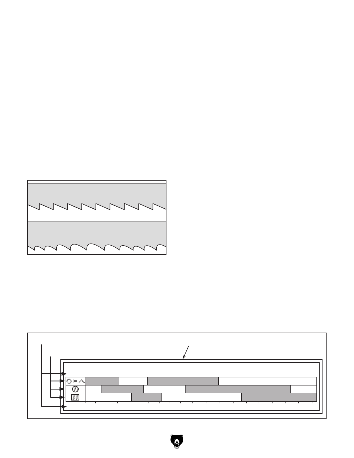
Blade Length
Measured by the blade circumference, blade
lengths are usually unique to the bandsaw model
and the distance between the wheels.
Model Blade Length Range
G0887 ............................................ 2311⁄2 "–2321⁄4"
Blade Pitch (TPI)
The chart below is a basic starting point for
choosing teeth per inch (TPI) for variable pitch
blades and standard raker set bi-metal blades/
HSS blades. However, for exact specifications of
bandsaw blades that are correct for your operation, contact the blade manufacturer.
Blade Width
Measured from the back of the blade to the tip of
the blade tooth (the widest point).
Model Blade Width
G0887 ............................................................ 11⁄2 "
Tooth Type
The most common tooth types are described as
follows, and illustrated in Figure 22.
Standard (or Raker)
Variable Pitch (VP)
Figure 22. Bandsaw blade tooth types.
Standard or Raker: Equally spaced teeth set
at "0" rake angle. Recommended for all purpose
use.
Variable Pitch (VP): Varying gullet depth and
tooth spacing, "0" rake angle, excellent chip
removing capacity, and smooth cutting.
To select correct blade pitch:
Measure material thickness. This measure-
1.
ment is distance from where each tooth
enters workpiece to where it exits workpiece.
Refer to "Material Width/Diameter" row of
2.
blade selection chart in Figure 23, and read
across to find workpiece thickness you need
to cut.
3. Refer to "Material Shapes" row and find
shape of material to be cut.
In applicable row, read across to right and
4.
find box where row and column intersect.
Listed in the box is minimum TPI recommended for variable tooth pitch blades.
The TPI range is represented by a "/" between
numbers. For example, 3/4 TPI is the same
as 3–4 TPI.
The "Cutting Speed Rate Recommendation"
chart, which is located on the machine just
below the Blade Pitch Chart, offers guidelines
for various metals, given in feet per minute
(FPM). Refer to Blade Speed Chart section
on Page 32 for further details.
Material Width/Diameter
Material Shapes
TOOTH SELECTION
mm
50
inch
2 3 4 5 6 7 8 9 10 11 12 13 14 15 16 17 18 192½ 3½
75 100 150 200 250 300 350 400
5/8
4/6
3/4
Figure 23. General guidelines for blade selection and speed chart.
Model G0887 (Mfd. Since 01/19)
3/4
Teeth Per Inch (TPI) for Bandsaw Blades
4/6
2/3
2/3 1.4/2.5
3/4
1.4/2.5
450
2/3
1.5/.8
1.5/.8
-29-
Page 39

Blade Breakage
Many conditions may cause a bandsaw blade to
break. Some of these conditions are unavoidable
and are the natural result of the stresses placed
on the bandsaw; other causes of blade breakage
are avoidable.
The most common causes of avoidable blade
breakage are:
Faulty alignment or adjustment of the blade
•
guides.
Feeding blade through the workpiece too
•
fast.
Blade Care &
Break-In
Blade Care
To prolong blade life, always use a blade with the
proper width, set, type, and pitch for each application. Maintain the appropriate feed rate and blade
speed, and pay attention to the chip characteristics (Refer to Blade Speed Chart on Page 32 and
Chip Inspection Chart on Page 33). Keep your
blades clean, since dirty or gummed up blades
pass through the cutting material with much more
resistance than clean blades, causing unnecessary heat.
Dull or damaged teeth.
•
• Improperly-tensioned blade.
Left blade guide assembly set too far from the
•
workpiece. Adjust left blade guide assembly
as close to workpiece as possible.
Using a blade with a lumpy or improperly fin-
•
ished braze or weld.
Leaving the blade tensioned when not in use.
•
• Using the wrong blade pitch (TPI) for the
workpiece thickness. The general rule of
thumb is to have no fewer than three teeth
in contact with the workpiece when starting a
cut and at all times during cutting.
Blade Break-In
The tips and edges of a new blade are extremely
sharp. Cutting at too fast of a feed rate or too
slow of a blade speed can fracture these tips and
edges, quickly dulling the blade. Properly breaking in a blade allows these sharp edges to wear
without fracturing, thus keeping the blade sharp
longer. Below is a typical break-in procedure. For
aftermarket blades, refer to the manufacturer's
break-in procedure to keep from voiding the
warranty.
Use the Chip Inspection Chart on Page 33 as
a guide to evaluate the chips and ensure that the
optimal blade speed and feed rate are being used.
To properly break in new blade:
Choose correct speed for blade and material
1.
type.
2. Reduce feed rate by half for first 50–100 in2
of material cut.
-30-
To avoid twisting blade when cutting, adjust
3.
feed rate when total width of blade is in cut.
Model G0887 (Mfd. Since 01/19)
Page 40

Setting Blade Feed
Changing Blade
Rate
The speed at which the saw blade will cut through
a workpiece is determined by blade type, feed
rate, and feed pressure. The feed rate is controlled by the blade feed-rate dial on the control
panel.
If the feed rate is not consistent, the headstock
spring tension (see Page 73) or flow control valve
(see Page 77) may need to be adjusted.
During operation, pay attention to the chips being
produced from the cut and compare them to the
Chip Inspection Chart on Page 33 to properly
set the downfeed rate.
Note: If a lubricant is used on the cut, the feed
rate can be increased by approximately 15% .
To set blade feed rate:
Speed
Model G0887 blade speeds: 106–315 FPM.
NOTICE
Only change speeds while the motor is running. Changing speeds when machine is
OFF may result in damage to your machine.
Always make sure belt guard is in use.
To change blade speeds:
1. Turn bandsaw ON and allow motor to reach
full speed.
2. Rotate blade speed dial (see Figure 25)
clockwise to decrease blade speed and counterclockwise to increase blade speed until
blade speed display shows desired speed.
Push hydraulic pump button ( ) to turn
1.
hydraulic pump ON.
Push raise headstock button ( ) and raise
2.
headstock to required height for workpiece.
Adjust blade feed-rate dial shown in Figure 24
3.
to desired feed rate from 0 (slowest) to
10 (fastest).
Feed Rate Dial
Figure 24. Feed rate dial.
Proceed with cutting operations.
4.
Blade Speed
Display
Blade Speed
Dial
Figure 25. Blade speed dial location.
5. Examine chips created from cutting opera-
tion, and adjust feed rate as necessary for
optimum cutting performance (refer to Chip
Inspection Chart on Page 33 for details).
Model G0887 (Mfd. Since 01/19)
-31-
Page 41

Blade Speed Chart
The chart in Figure 26 offers blade speed guidelines for various metals, given in feet per minute (FPM)
and meters per minute (M/Min). Choose the closest available speed on the machine, then adjust the feed
rate as necessary, using the appearance of the chips produced as a guide. Refer to the Chip Inspection
Chart that follows for recommendations on adjusting feed rate or blade speed based on the appearance of
the chips produced.
Material
Carbon
Steel
Angle
Steel
Thin Tube
Aluminum
Alloy
Copper
Alloy
Speed FPM
(M/Min)
196~354
(60) (108)
180~220
(54) (67)
180~220
(54) (67)
220~534
(67) (163)
229~482
(70) (147)
Material
Tool Steel
High-
Speed
Tool Steel
Cold-Work
Tool Steel
Hot-Work
Tool Steel
Oil-
Hardened
Tool Steel
Speed FPM
(M/Min)
203
(62)
75 ~118
(25) (36)
95~213
(29) (65)
203
(62)
203~213
(62) (65)
Figure 26. Blade speed chart.
Material
Alloy Steel
Mold Steel
WaterHardened
Tool Steel
Stainless
Steel
CR
Stainless
Steel
Speed FPM
(M/Min)
111~ 321
(34) (98)
246
(75)
242
(74)
85
(26)
85~203
(26) (62)
Material
Free
Machining
Stainless
Steel
Gray Cast
Iron
Ductile
Austenitic
Cast Iron
Malleable
Cast Iron
Plastics &
Lumber
Speed FPM
(M/Min)
150~203
(46) (62)
108~225
(33) (75)
65~85
(20) (26)
321
(98)
220
(67)
-32-
Model G0887 (Mfd. Since 01/19)
Page 42

Chip Inspection Chart
The best method for choosing the cutting speed and feed rate for a cutting operation is to inspect the chips
created by the cut. These chips are indicators of what is commonly referred to as the "chip load." Refer to
the chip inspection chart below to evaluate chip characteristics and determine whether to adjust feed rate/
pressure, blade speed, or both.
Chip
Appearance
Chip
Description
Thin & Curled Silver Good Good
Hard, Thick &
Short
Hard, Strong &
Thick
Hard, Strong,
Curled & Thick
Hard, Coiled &
Thin
Straight & Thin Silver Good Increase
Powdery Silver Decrease Increase
Coiled, Tight &
Thin
Figure 27. Chip inspection chart.
Chip
Color
Brown or Blue Increase Decrease
Brown or Blue Increase Decrease
Silver or Light
Brown
Silver Increase Decrease
Silver Good Decrease
Blade
Speed
Good
Feed Rate/
Pressure
Decrease
Slightly
Other
Actions
Check Blade
Pitch
Check Blade
Pitch
Check Blade
Pitch
Model G0887 (Mfd. Since 01/19)
-33-
Page 43

Changing Blade
All saw blades are dangerous and may cause personal injury. To reduce
the risk of being injured,
wear leather gloves when
handling and uncoiling saw
blades.
5. Clean out all chips and shavings with a brush
and shop vacuum.
Remove both blade guards and blade guard
6.
extension by removing (6) button head cap
screws and flat washers (see Figure 29).
x 2
Item(s) Needed Qty
Assistant ............................................................ 1
Leather Gloves (per person)
Hex Wrench 4mm
Blades should be changed when they become
dull, damaged, or when cutting materials that
require a blade of a certain type or tooth count.
To change blade:
Push hydraulic pump button ( ) to turn
1.
hydraulic pump ON.
Push raise headstock button ( ) and raise
2.
headstock approximately 6 inches.
DISCONNECT MACHINE FROM POWER!
3.
4. Open wheel cover by removing (4) button
head cap screws (see Figure 28).
.............................................. 1
.............................. 1
Right Blade
Guard
x 2
Figure 29. Location of blade guards and blade
guard extension.
Release blade tension by turning blade
7.
tension handwheel counterclockwise (see
Figure 30).
x 2
Left Blade
Guard
Blade Guard
Extension
Figure 28. Blade cover secure screws (2 of 4).
-34-
Blade
Tension
Handwheel
Figure 30. Location of blade tension handwheel.
Model G0887 (Mfd. Since 01/19)
Page 44

8. Remove blade, beginning at top of blade
wheels.
With help of an assistant, insert new blade
9.
through both blade guides and bearings (see
Figure 31), then position it around wheels.
Blade
Blade Guide
Brush
Bearings
Figure 31. Installing new blade.
10. Apply a light amount of tension to hold blade
in place. Work your way around blade to
adjust position so back of blade is against
shoulder of wheels, as shown in
Figure 33.
Wheel
Shoulder
Blade
Figure 33. Blade installed on wheels.
11
. Perform Tensioning Blade procedure that
follows this section.
Note: It is sometimes possible to flip the
blade inside out, in which case the blade
will be installed in the wrong direction. After
installing, check to make sure the blade
teeth face the same direction as blade travel
(see Figure 32). Some blades will have a
directional arrow as a guide.
Blade Travel
Figure 32. Example of blade cutting direction.
12. Install blade guards and blade guard exten-
sion, then close and secure wheel cover.
Ensure guards do not touch blade.
. Reposition left blade guide (refer to Blade
13
Guides on Page 37 for details).
Model G0887 (Mfd. Since 01/19)
-35-
Page 45

Tensioning Blade
— If there is just enough space to fit fin-
gernail, then blade tracking is properly
adjusted. Continue to
Step 3.
Proper blade tension is essential to avoid blade
vibration, twist, or slippage on the wheels. A correctly tensioned blade provides long blade life,
straight cuts, and efficient cutting.
The three major signs of incorrect blade tension
are: 1) The blade stalls in the cut and slips on the
wheels, 2) the blade frequently breaks, and 3) the
bandsaw does not make straight cuts.
The blade tension failure indicator light will illuminate and the control panel will beep (see
Identifying Failures on Page 40) if the bandsaw
is turned ON and the tension is not set correctly.
Loosen blade tension at the end of each day
to prolong blade life.
Tools Needed Qty
Hex Wrench 4mm .............................................. 1
If there is too little or too much space to
—
fit fingernail, then blade tracking must be
properly adjusted before tensioning blade.
(Refer to Adjusting Blade Tracking on
Page 68.)
4.
Remove blade guard extension (see
Figure 35).
x 2
Blade Guard
Extension
To tension blade:
DISCONNECT MACHINE FROM POWER!
1.
Open wheel cover by removing (4) button
2.
head cap screws (see Figure 34).
Figure 34. Wheel cover secure screws (2 of 4).
Figure 35. Blade guard extension location.
Loosen adjustable handle on left blade guide
5.
arm and move arm as far left as it will go
Figure 36). Tighten adjustable handle to
(see
secure arm position.
Adjustable
Handle
Left Blade
Guide Arm
Figure 36. Left blade guide adjustable handle.
3.
Perform quick blade tracking check by sliding
fingernail between end of blade and wheel
shoulder.
-36-
Model G0887 (Mfd. Since 01/19)
Page 46

6. Turn blade tension handwheel (see
Figure 37) clockwise to tighten blade or
counterclockwise to loosen blade.
— Adjust blade tension handwheel until indi-
cator on blade tension gauge moves into
green section (21,000 to 24,000 PSI).
Adjusting
Blade Guides
The left blade guide should be as close to the
workpiece as possible during cutting operations.
This will help ensure straight cuts by keeping the
blade from twisting and drifting off the cut line.
Blade
Tension
Handwheel
Figure 37. Blade tension handwheel and gauge
location.
7.
Close and secure wheel cover.
Blade
Tension
Gauge
To adjust the left blade guide, loosen the adjustable handle on the left blade guide arm (see
Figure
workpiece as possible, then tighten the adjustable
handle. Whenever the blade guide is adjusted,
the blade guard extension should also be adjusted (see Adjusting Blade Guard Extension on
Page 38).
38) and slide the arm/guide as close to the
Adjustable
Handle
Left Blade Guide
Left Blade
Guide Arm
Model G0887 (Mfd. Since 01/19)
Figure 38. Left blade guide components.
The right blade guide has a wire brush that makes
contact with the blade to help clear away chips
and extend blade life (see Figure 39).
Blade Brush
(Hidden By Guard)
Figure 39. Blade brush location.
-37-
Page 47

Adjusting Blade
3. Loosen (2) button head cap screws shown in
Figure 41.
Guard Extension
The blade guard extension provides support for
the left blade guard. When the left blade guide
is adjusted to the right, the left blade guard is
extended from under the blade cover to cover
the exposed blade. Adjust the blade guard extension so the left blade guard is as supported as
possible.
Tool Needed Qty
Hex Wrench 4mm .............................................. 1
To adjust blade guard extension:
DISCONNECT MACHINE FROM POWER!
1.
Open wheel cover by removing (4) button
2.
head cap screws (see Figure 40).
Adjust blade guard extension until left blade
4.
guard is supported, then tighten screws from
Step 3 to secure (see Figure 41).
x 2
Left Blade
Guard
Blade Guard
Extension
Figure 41. Blade guard extension components.
Figure 40. Wheel cover secure screw locations
(2 of 4).
-38-
Model G0887 (Mfd. Since 01/19)
Page 48

Manual & Automatic
Controls
6. Raise headstock ( ) to height set in Step 4.
Open vise ( ), place workpiece for cut, then
7.
close vise ( ).
The Model G0887 has two operation modes:
automatic and manual. Manual mode includes
the controls necessary to prepare a workpiece
for a cutting operation while automatic mode will
complete the cut through a series of pre-established settings. Manual mode can be used to
accomplish the same operation as the automatic
mode, but the automatic mode requires less user
intervention and therefore result in less user error.
See the following steps for the controls required
for each to accomplish a typical cutting operation
(see Figure 42).
8. Proceed to Performing an Automatic Cut.
Performing an Automatic Cut
Automatic mode can only be used to perform a
cut when the preceding manual setup steps have
been performed (see Preparing a Cut).
To perform an automatic cut:
Open coolant valves (see Figure 43).
1.
Figure 42. Manual and automatic controls.
Preparing a Cut
Plan your cut before connecting to power, and
determine whether the vise or support vise components will need to be moved out of the blade
path (see Using Vise on Page 42).
To prepare a cut:
Connect machine to power and turn both
1.
master power switches ON.
Enter manual mode ( ).
2.
3. Turn on hydraulic pump ( ).
4. Set headstock height (see Setting Headstock
Height on Page 40).
Figure 43. Coolant valve (1 of 3) opened.
2. Enter automatic mode ( ).
Press auto cycle button ( ).
3.
— Coolant pump and blade will start. Turn
feed rate dial to adjust feed rate and headstock will lower to complete cut.
— When cut is complete, blade will stop,
headstock will raise, and vise will open to
release workpiece.
Note: If pre-established settings are incorrect
for operation, or if a motor has overloaded,
light(s) on failure indicator will illuminate.
User intervention is required before automatic cut can take place (see Identifying
Failures on Page 40).
Set headstock angle (see Setting Headstock
5.
Angle on Page 41).
Model G0887 (Mfd. Since 01/19)
-39-
Page 49

Identifying Failures
The control panel comes equipped with a failure
indicator panel, which will illuminate if a setting
needs to be addressed in order to perform an
operation.
If one of the lights illuminates, edit the setting
indicated to proceed with your operation (see
Figure 44).
Setting Headstock
Height
The height that the headstock will travel is controlled by the control panel (see
Headstock height should be set to match the
height of the workpiece. This speeds up repetitive
cuts by eliminating unnecessary headstock travel.
Figure 45).
A
B
D
I
Figure 44. Failure indicator panel.
A. Blade Tension: Blade tension is not correct.
Control panel will beep until correctly set (see
Tensioning Blade on Page 36).
B. Blade Cover: Blade cover is open. Control
panel will beep and will not operate until
cover is closed.
C. Blade Motor: Blade motor is overloaded.
D. Height: Headstock needs to be raised or
height is at or higher than height limit setting (see Setting Headstock Height).
E. Downfeed Limit: Downfeed limit is not set
correctly or downfeed limit switch is engaged
(see Adjusting Downfeed Stop Bolt on
Page 72).
F. Coolant Pump: Coolant pump motor is over-
loaded.
H
G
F
C
E
Input Light
Increase
Button
Height Control
Button
Figure 45. Headstock height controls.
To set headstock height:
Enter manual mode ( ).
1.
2. Turn on hydraulic pump ( ).
3. Press height control button ( ) to edit head-
stock height setting (see
Use headstock increase/decrease buttons
4.
to adjust height until headstock digital readout displays desired height (see
Each press will change height by 25mm.
Input light will illuminate while in edit
—
mode. Once setting has not been adjusted
for two seconds, light will go out to signal
that setting has been inputted. If input light
does not go out, headstock is currently at
or above height limit.
Headstock
Digital Readout
Decrease
Button
Figure 45).
Figure 45).
G. Hydraulic Power Unit: Hydraulic motor is
overloaded.
H. Vise: Open and close vise to secure
workpiece (see Using Vise on Page 42).
I. Emergency Stop Button: Emergency Stop
button is depressed. Twist to reset.
-40-
Raise headstock ( ) to highest position.
5.
— Input light will illuminate and headstock
will not raise further when height value is
reached.
Model G0887 (Mfd. Since 01/19)
Page 50

Setting Headstock
Angle
The headstock can be swiveled to cut angles from
0°–60° to the left or right for a total swing of 120°.
The headstock angle is controlled with hydraulics,
and can be adjusted using the headstock control
section of the control panel (see Figure 46).
Setting Angle Other Than 0°
Set the angle to the absolute value then use the
joystick to swivel the headstock in either direction.
For example, inputting 15° will allow the headstock to swivel 15˚ or -15˚.
To set headstock angle:
Enter manual mode ( ).
1.
2. Turn on hydraulic pump ( ).
Input Light
Increase
Button
Headstock Angle
Joystick
Figure 46. Headstock control section.
If an operation will require the removal of the
movable vise, usually the workpiece can be repositioned or oriented to allow for a left angle cut
instead to allow for vise support.
Before adjusting headstock angle, always
consider any clamping or vise components
that may interfere with headstock
movement. If headstock contacts anything
while moving, it could result in operator or
bystander injury and damage machine.
Angle Control
Button
Headstock
Digital Readout
Decrease
Button
3. Raise headstock ( ) to highest position.
Note: If headstock does not clear vise and
table components at highest position, set
headstock height higher so it will (see Setting
Headstock Height on Page 40).
Press angle control button ( ) to edit head-
4.
stock angle setting (see Figure 46).
Use headstock increase/decrease buttons to
5.
adjust angle until headstock digital readout
displays desired angle (see Figure 46). Each
press will change angle by 0.2°.
Once setting has not been adjusted for
—
two seconds, value will return to current
headstock angle to indicate it has been
inputted.
Use headstock angle joystick to adjust head-
6.
stock until desired angle is displayed.
Headstock will not travel further than
—
inputted angle setting in either direction.
As headstock approaches target angle,
—
headstock will jog and stop so as not to
pass target.
Model G0887 (Mfd. Since 01/19)
-41-
Page 51

Setting Angle to 0°
The control panel has been calibrated at the factory to return the headstock angle to 0°.
To set angle to 0°:
Using Vise
Enter manual mode ( ).
1.
2. Turn on hydraulic pump ( ).
3. Raise headstock ( ) to highest position.
Note: If headstock does not clear vise and
table components at highest position, set
headstock height higher so it will (see Setting
Headstock Height on Page 40).
Press angle control button ( ) to edit head-
4.
stock angle setting (see Figure 47).
Press both headstock increase and decrease
5.
buttons and hold them until headstock digital
readout changes to zero (see Figure 47).
Wait until headstock digital readout returns
6.
to current angle, then use headstock angle
joystick to adjust headstock to 0° (see
Figure 47).
To avoid serious injury, always turn saw
OFF and allow blade to come to complete
stop before adjusting vise!
The Model G0887 vise consists of a movable
vise jaw that is manually positioned near the
workpiece, hydraulic vise clamping controls for
opening and closing, and adjustable vise clamping pressure.
Adjusting Vise Clamping Pressure
The Model G0887 features adjustable clamping pressure so the vise will not crush fragile
workpieces.
Tool Needed Qty
Open-End Wrench 27mm .................................. 1
To adjust vise clamping pressure:
Loosen nut shown in Figure 48.
1.
Input Light
Increase
Button
Headstock Angle
Joystick
Figure 47. Headstock control section.
Angle Control
Button
Headstock
Digital Readout
Decrease
Button
Adjust pressure adjustment knob until desired
2.
pressure on gauge has been achieved, then
tighten nut to secure (see Figure 48).
IMPORTANT: Do not exceed 497 PSI
(35 kg/cm²).
Gauge
Nut
Figure 48. Vise clamping pressure adjustment
components.
Pressure
Adjustment
Knob
-42-
Model G0887 (Mfd. Since 01/19)
Page 52

Moving Movable Vise Jaw
Once the headstock angle has been adjusted,
move the movable vise jaw as close to the blade
as possible to provide the utmost support for the
workpiece. Only move the jaw along the dovetail
track where it can secure workpiece without intersecting blade path.
To open and close vise:
Turn ON hydraulics ( ).
1.
2. Push vise open button ( ) to release any
pressure on movable vise jaw.
Insert workpiece between jaws.
3.
To move movable vise jaw:
DISCONNECT MACHINE FROM POWER!
1.
2. Loosen vise position lock handle by turning
handle counterclockwise (see Figure 49).
Push or pull movable vise on vise track until
3.
it is close to blade but will not intersect blade
path (see Figure 49).
Movable
Fixed
Vise
Dovetail Vise
Track
Vise Position
Lock Handle
Vise Jaw
Note: Figure 51 shows correct methods of
holding different workpiece shapes.
INCORRECT CORRECT
Figure 51. Example of workpiece holding options
by material shape.
Figure 49. Location of vise components.
4. Secure vise position by tightening vise posi-
tion lock handle.
Opening and Closing Vise
The hydraulics that open and close the movable
vise can be adjusted using the control panel (see
Figure 50).
Vise Close
Button
Vise Open
Button
Figure 50. Vise controls.
Model G0887 (Mfd. Since 01/19)
Push vise close button ( ) to clamp
4.
workpiece. Between cuts, use vise open button (
new workpiece.
) to release and reposition/reload a
-43-
Page 53

Adjusting
Support Vise Guide
The support vise guide provides workpiece support on the outfeed side of the cut, guiding cut-off
pieces down the cutoff chute. The support vise
guide should be adjusted when the cut had been
planned and the workpiece has already been
clamped in the vise. Use the adjustment controls
(see Figure 52) to support the workpiece close to
where the blade will contact it.
Extension
Lock Handle
Position
Lock Handle
Fine-Adjustment
Handle
Vise
Guide
Adjusting Work Stop
The Model G0887 is equipped with a work stop
for repetitive cutting operations up to 24" long.
The work stop will need to be adjusted any time it
is removed or repositioned.
To adjust work stop:
Adjust headstock to desired angle.
1.
Lower headstock completely.
2.
DISCONNECT MACHINE FROM POWER.
3.
Screw work stop support rod into hole in
4.
outfeed table with scale facing upward, as
shown in
Figure 53.
Flat
Edge
Figure 52. Support vise guide adjustment
controls.
To adjust support vise guide:
Loosen position lock handle (see Figure 52).
1.
Move vise guide close to planned cut on vise
2.
track (see Figure 52).
Tighten position lock handle to secure posi-
3.
tion.
Loosen extension lock handle (see Figure 52).
4.
Adjust support vise guide until it contacts
5.
workpiece (see Figure 52).
Tighten extension lock handle.
6.
Tighten fine-adjustment handle until plate is
7.
secure against workpiece (see Figure 52).
Outfeed Table
Hole
Support Rod
Figure 53. Work stop bar installed in table.
5.
Slide work stop bracket onto support rod,
aligning body with "0" mark on rod scale (see
Figure 54).
0 Mark
Body
Figure 54. Work stop bracket adjusted to 0
mark.
Support Rod
-44-
Model G0887 (Mfd. Since 01/19)
Page 54

6. Tighten bracket lock handle to secure at 0"
(see Figure 55).
Using Coolant
Loosen distance rod lock handle and adjust
7.
distance rod until hex bolt on rod just touches
blade (see Figure 55).
Tighten distance rod handle to secure.
8.
— Confirm hex bolt still touches blade. If
it does not, adjust hex bolt until it does,
then tighten jam nut to secure setting
(see Figure 55).
Blade
Distance Rod
Jam Nut
Hex Bolt
Distance Rod
Lock Handle
System
Coolant is a mixture of cutting fluid and water.
While simple in concept and function, many
issues must be taken into account to mix and
use the correct coolant. Always follow all product
warnings and specifications, and contact the cutting fluid manufacturer for unanswered questions.
Use the information below as a guideline to
choose the appropriate coolant. Always refer to
the cutting fluid manufacturer for specific application and safety information:
• For cutting low alloy, low carbon, and general-purpose category metals with a bi-metal
blade , use a water-soluble cutting fluid.
• For cutting stainless steels, high carbon, and
high alloy metals, brass, copper, and mild
steels, use "Neat Cutting Oil" (commonly
undiluted mineral oils) that have extreme
pressure additives (EP additives).
Figure 55. Work stop adjusted to "0", touching
blade.
9. Loosen bracket lock handle, adjust work stop
bracket to depth of cut indicated on support
rod scale, then tighten to secure.
Connect to power, turn on hydraulics, then
10.
raise headstock.
Place workpiece in vise against table, aligned
11.
with work stop (see Figure 56).
Workpiece
Work Stop
• For cutting cast iron, coolant is not
recommended.
Tip: Using a refractometer or hydrometer to
replenish water in water-based coolant can extend
the life of blades and coolant, and ensure consistent cutting results.
BIOLOGICAL AND POISON
HAZARD! Use proper personal protection equipment
when handling coolant and
follow federal, state, and
fluid manufacturer requirements to properly dispose
of coolant.
Figure 56. Work stop set for cutting operation.
Model G0887 (Mfd. Since 01/19)
-45-
Page 55

FIRE HAZARD! DO NOT cut
magnesium when using oilwater solutions as coolant!
Always use coolant intended for magnesium. Water in
the solution could cause a
magnesium-chip fire.
This bandsaw has a built-in coolant system
that can extend the life of your bandsaw blades
by lowering the temperature of the blade and
workpiece if used properly when cutting.
Note: Too much flow at the fluid nozzle will make
a mess and can make the work area unsafe; and
not enough fluid at the cut will overheat the blade,
causing the blade teeth to load up and break.
IMPORTANT: Monitor coolant level frequently to
keep system working properly. DO NOT let coolant level fall below halfway level on filter screen
(see Figure 58).
NEVER run machine without coolant in
the reservoir or when coolant is below low
mark or you will overheat pump and void
warranty!
Using Coolant System
Add coolant (refer to Adding Coolant on Page
57) before using coolant system.
Turn coolant pump ON with the coolant pump button (
to control flow of cutting fluid (see Figure 57).
) on the control panel. Open coolant valves
Coolant Valve
Filter
Screen
Figure 58. Example of halfway level on filter
screen.
Halfway
Line
Using Spray Gun
The auxiliary hose and sprayer can be used to
rinse metal chips into the reservoir.
1. Position splash guard on side of base near
location of spraying operation.
Close coolant control valves.
2.
Press coolant pump button ( ). Coolant will
3.
now spray when the trigger is pressed (see
Figure 59).
Figure 57. Coolant valve (1 of 3) open.
-46-
Figure 59. Example of spray gun in use.
Model G0887 (Mfd. Since 01/19)
Page 56

ACCESSORIES
Installing unapproved accessories may
order online at www.grizzly.com or call 1-800-523-4777
SECTION 5: ACCESSORIES
cause machine to malfunction, resulting in
serious personal injury or machine damage.
To reduce this risk, only install accessories
recommended for this machine by Grizzly.
NOTICE
Refer to our website or latest catalog for
additional recommended accessories.
H9240—Water Soluble Machining Oil
Rustlick water soluble machining oil contains
effective chlorinated E.P. additive to provide excellent tool life. Guaranteed to protect neoprene
seals. Great for general purpose or heavy duty
applications. Can be used on all metals except
titanium.
Replacement Bi-Metal Bandsaw Blades
T30690—232" x 1
T30691—232" x 1
T30692—232" x 1
T30693—232" x 1
Figure 60. Typical variable pitch bi-metal cutting
T28172—14" x 39" Heavy-Duty Roller Table
Use this versatile roller table wherever you need
extra workpiece support.
1
⁄2" x 0.051 2–3 TPI
1
⁄2" x 0.051 3–4 TPI
1
⁄2" x 0.051 4–6 TPI
1
⁄2" x 0.051 5–8 TPI
blade.
Figure 62. H9240 Rustlick Machining Oil.
T21321—Hand Punch
For repetitive hole punching, nothing beats the
speed of a hand punch. With a throat depth of
6 9⁄32", this versatile punch can make a hole in mild
steel up to
tall (without handle). Approximate shipping weight:
192 lbs.
3
⁄16" thick. Measures 5 1⁄2 " wide by 31 1⁄2 "
Figure 63. Model T21321 Hand Punch.
Figure 61. T28172 Heavy-Duty Roller Table.
Model G0887 (Mfd. Since 01/19)
-47-
Page 57

Basic Eye Protection
order online at www.grizzly.com or call 1-800-523-4777
T20501—Face Shield Crown Protector 4"
T20502—Face Shield Crown Protector 7"
T20503—Face Shield Window
T20451—“Kirova” Clear Safety Glasses
T20452—“Kirova” Anti-Reflective S. Glasses
T20456—DAKURA Safety Glasses
T20502
H6572—Grease-Resistant Mat 3' x 3' x 3⁄4"
These Black Grease Resistant Mats are engineered for proper back and leg support, using
super-tough virgin rubber material. The nonslip surface features a modular interlock design,
which enables the user to create a custom floor.
Mats measure 36" x 36" x
3
⁄4".
T20503
T20456
Figure 64. Assortment of basic eye protection.
T20452
T20451
Milwaukee® Performance Work
Gloves
T31087—S
T31088—M
T31089 —L
T31090 —XL
T31091—XXL
Milwaukee® Performance Work Gloves are
designed to provide ultimate durability and all day
comfort.
Figure 66. Model H6572 Grease-Resistant Mat
3' x 3' x
T30024—Powered Respirator Kit
This respirator kit is a lightweight, comfortable,
and easy to carry device for protecting the airway
from small particulates. Requires 4 AA batteries
(not included).
3
⁄4".
Figure 67. Model T30024 Powered Respirator
Kit.
Figure 65. Milwaukee® Performance Work
Gloves.
-48-
Model G0887 (Mfd. Since 01/19)
Page 58

SECTION 6: MAINTENANCE
accidental startup, always
disconnect machine from
Cleaning &
To reduce risk of shock or
power before adjustments,
maintenance, or service.
Schedule
For optimum performance from this machine, this
maintenance schedule must be strictly followed.
Ongoing
To minimize your risk of injury and maintain proper
machine operation, shut down the machine immediately if you ever observe any of the items below,
and fix the problem before continuing operations:
• Loose mounting bolts.
• Damaged or dull saw blade.
Worn or damaged wires.
•
Any other unsafe condition.
•
Protecting
Use a brush and shop vacuum to remove chips
and other debris from the working surfaces.
Remove any rust build-up from unpainted cast
iron surfaces of your machine and treat with a
non-staining lubricant after cleaning.
Keep unpainted cast iron surfaces rust-free with
regular applications of products like G96
Treatment, SLIPIT
G2871—Boeshield
G2870—Boeshield
Perfect for unpainted cast iron surfaces, this
ozone-friendly protective spray penetrates deep
and really holds up against corrosive environments. Lubricates metals for months and is also
safe for use on most paints, plastics, and vinyls.
Developed by Boeing engineers for aircraft applications—this is the best!
®
, or Boeshield® T-9.
®
T-9 12 Oz. Spray
®
T-9 4 Oz. Spray
®
Gun
Daily Maintenance
• Lubricate blade and blade guides (Page 51).
• Clean/lubricate table and vise (Page 51).
Weekly Maintenance
• Lubricate headstock pivot points (Page 52).
• Lubricate blade speed pulley (Page 52).
• Lubricate vise shaft (Page 52).
• Lubricate blade guide arm gib (Page 52).
• Lubricate front wheel axle (Page 52).
• Lubricate blade tension leadscrew (Page 53).
Monthly Check
• Inspect drive belt (Page 58).
Model G0887 (Mfd. Since 01/19)
Figure 68. Boeshield® T-9 spray.
-49-
Page 59

Lubrication
Use the schedule below and the following instructions to properly lubricate the other components
that require lubrication.
Frequency
Lubrication Task
Blade & Guides 8 Hrs.
Table & Vise 8 Hrs.
Headstock Pivot Points 40 Hrs.
Blade Speed Pulley 40 Hrs.
Vise Shaft 40 Hrs.
Blade Guide Arm Gib 40 Hrs.
Front Wheel Axle 40 Hrs.
Blade Tension Leadscrew 40 Hrs.
Figure 69. Recommended lubrication tasks.
Item(s) Needed Qty
NLGI#2 Grease (T26419 or Equivalent) . As Needed
ISO 68 Oil (SB1365 or Equivalent)
Clean Shop Rags
Grease Gun
Stiff Brush
Clean Brush
Hex Wrench 4, 5mm
.................................................................1
.................................... As Needed
..............................................................1
..............................................................1
.........................................1 Ea.
(Hours of
Operation)
......... As Needed
Page
Ref.
51
51
52
52
52
52
52
53
T26419—Syn-O-Gen Synthetic Grease
Formulated with 100% pure synthesized hydrocarbon basestocks that are compounded with special
thickeners and additives to make Syn-O-Gen
non-melt, tacky, and water resistant. Extremely
low pour point, extremely high temperature oxidation, and thermal stability produce a grease that is
unmatched in performance.
Figure 70. Model T26419 Syn-O-Gen Synthetic
Grease.
SB1365—South Bend Way Oil-ISO 68
Engineered for the high pressure exerted on
horizontal or vertical ways and slides. Protects
against rust and corrosion. Ensures stick-free,
smooth motion which maximizes finishes and
extends the life of your machine. Won’t gum up!
12 oz. AMGA#2 (ISO 68 Equivalent)
-50-
Figure 71. Model SB1365 Way Oil.
Model G0887 (Mfd. Since 01/19)
Page 60

Blade & Blade Guides
Lube Type ............. SB1365 or ISO 68 Equivalent
Oil Amount
Lubrication Frequency
...........................................1–2 Drops
................................. Daily
Headstock Pivot Points
Lube Type ............. T26419 or NLGI#2 Equivalent
Amount
Lubrication Frequency
.............................................. 1–2 Pumps
..............................Weekly
Place one or two drops of light machine oil on
blade and blade guides (see
especially when cutting cast iron, as no coolant is
required when cutting cast iron.
Left Blade
Guide
Figure 72. Blade and blade guides.
Figure 72) daily,
Right Blade
Guide
Table & Vise
Lube Type ............. SB1365 or ISO 68 Equivalent
Oil Amount
Lubrication Frequency
............................................Thin Coat
................................. Daily
Apply grease to headstock pivot pin and hydraulic
cylinder bearing using grease fittings shown in
Figures 74 –75.
Pivot Pin
Grease Fitting
Pivot Pin
Grease Fitting
Keep the vise and table (see
rust-free with regular applications of a quality way
oil.
Figure 73. Table and vise.
Figure 73) surface
Figure 74. Pivot pin grease fitting locations.
Hydraulic Cylinder
Bearing
Grease Fitting
Figure 75. Hydraulic cylinder bearing grease
fitting location.
Model G0887 (Mfd. Since 01/19)
-51-
Page 61

Blade Speed Pulley
Lube Type ............. T26419 or NLGI#2 Equivalent
Amount
Lubrication Frequency
.............................................. 1–2 Pumps
..............................Weekly
Blade Guide Arm Gib
Lube Type ............. SB1365 or ISO 68 Equivalent
Oil Amount
Lubrication Frequency
............................................Thin Coat
..............................Weekly
Apply grease to blade speed pulley using grease
fitting shown in
Figure 76. Blade speed pulley grease fitting
Figure 76.
Blade Speed
Pulley
Grease Fitting
location.
Vise Shaft
Lube Type ............. T26419 or NLGI#2 Equivalent
Amount
Lubrication Frequency
.............................................. 1–2 Pumps
..............................Weekly
Keep the unpainted surfaces of the blade guide
arm gib (see
applications of a quality way oil.
Figure 78. Blade guide arm gib.
Figure 78) rust-free with regular
Blade Guide
Arm Gib
Front Wheel Axle
Lube Type ............. T26419 or NLGI#2 Equivalent
Amount
Lubrication Frequency
.............................................. 1–2 Pumps
..............................Weekly
Apply grease to vise shaft using grease fitting
shown in
Figure 77. Vise shaft grease fitting location.
Figure 77.
Vise Shaft
Grease Fitting
Apply grease to front wheel axle using grease fitting shown in
Figure 79. Front wheel axle grease fitting
Figure 79.
Front Wheel Axle
Grease Fitting
location.
-52-
Model G0887 (Mfd. Since 01/19)
Page 62

Blade Tension Leadscrew
Lube Type ............. SB1365 or ISO 68 Equivalent
Oil Amount
Lubrication Frequency
...........................................1–2 Drops
..............................Weekly
Hydraulic System
The blade tension leadscrew can be found behind
the blade tension assembly cover, and can be
accessed by removing the four securing cap
screws (see Figure 80).
x 4
Blade Tension
Assembly Cover
Figure 80. Blade tension assembly cover and
securing cap screws.
Lubricate the blade tension leadscrew with 1–2
drops of light machine oil weekly (see
Wipe off excess oil with a clean rag.
Blade Tension
Leadscrew
Figure 81).
Always wear safety goggles when servicing the
hydraulic system.
The hydraulic system must be maintained on a
regular basis and kept in good operating condition
to avoid premature wear of moving parts, hoses,
and valves.
If you have never maintained a hydraulic system
before, WE STRONGLY RECOMMEND that you
read books, get formal training, or seek the help
of a qualified hydraulic service technician.
Hydraulic systems are highly pressurized
and hydraulic fluid is hot after use. Should
a leak or malfunction take place, any
maintenance to hydraulic lines and valves
should only occur when hydraulic pressure
has been relieved and fluid has cooled.
Checking Hydraulic Pressure
The hydraulic system pressure should not exceed
498 PSI. Use the following steps to check the system pressure and adjust it as needed.
Figure 81. Blade tension leadscrew location.
Model G0887 (Mfd. Since 01/19)
Item(s) Needed Qty
Hex Wrench 4mm .............................................. 1
Open-End Wrench 17, 27mm
To check hydraulic pressure:
1
. Raise/lower headstock repeatedly for approx-
imately 10 minutes to warm up hydraulic fluid.
. DISCONNECT MACHINE FROM POWER!
2
......................1 Ea.
-53-
Page 63

3. Remove hydraulic power unit access panel
(see Figure 82).
Checking Hydraulic Fluid
The hydraulic fluid level and temperature should
be checked weekly.
Item(s) Needed Qty
Safety Goggles .................................................. 1
Hex Wrench 4mm
T23963 or ISO 32 Equivalent
Funnel
................................................................ 1
.............................................. 1
............ As Needed
Hydraulic
Power Unit
Access Panel
Figure 82. Hydraulic power unit access panel
location.
4. Check pressure gauges shown in Figure 83.
Gauges should read less than 498 PSI.
— If vise pressure gauge reads more than 498
PSI, refer to Adjusting Vise Clamping
Pressure on Page 42 to adjust pressure.
— If manifold pressure gauge reads more
than 498 PSI, proceed to Step 5.
— If both gauges reads 498 PSI or less, no
adjustment is necessary. Install hydraulic
power unit access panel.
Vise
Pressure
Gauge
To check hydraulic fluid:
1. Raise/lower headstock repeatedly for approx-
imately 10 minutes to warm up hydraulic fluid.
. DISCONNECT MACHINE FROM POWER!
2
Remove hydraulic power unit access panel
3.
(see Figure 82).
Check fluid temperature on thermome-
4.
ter mounted to hydraulic fluid tank (see
Figure
between 50–95°F (10–35°C).
— If fluid temperature exceeds 140°F (60°C),
Remove tank cap (see Figure 84) and inspect
5.
for burnt-smelling or tan-colored, water-contaminated hydraulic fluid.
84). The temperature should read
stop machine immediately and allow fluid
to cool down. Review Troubleshooting
on Page
fix the problem, contact a qualified hydraulic service technician or Tech Support.
60 for solutions. If you still cannot
Manifold
Pressure
Gauge
Figure 83. Location of pressure gauges.
5. Adjust pressure relief valve until mani-
fold gauge displays 498 PSI or less (see
Hydraulic System Diagram on Page 77).
Note: Connect machine to power and
run hydraulic system to check pressure
adjustment.
-54-
— If fluid is contaminated, proceed to
Changing Hydraulic Fluid.
Fill Cap
Fluid Gauge
Figure 84. Hydraulic tank fluid gauge and fill cap
location.
Model G0887 (Mfd. Since 01/19)
Page 64

6. Check fluid level. Fluid should just cover the
bottom of the fill screen (see
Proper Fluid Level
Figure 85. Example of proper fluid level.
Figure 85).
Fill Screen
3.
Remove hydraulic power unit access panel
(see Figure 86).
Hydraulic
Power Unit
Access Panel
Figure 86. Hydraulic power unit access panel
location.
— If fluid level is low, slowly add hydraulic
fluid until it just covers the bottom of the fill
screen.
7. Install fill cap and hydraulic unit access panel.
Changing Hydraulic Fluid
The hydraulic fluid should be changed and the
fluid tank cleaned every 5,000 hours of use.
Item(s) Needed Qty
T23963 or ISO 32 Equivalent .................... 30 Qt.
Safety Goggles
Hex Wrench 4, 5mm
Wood Blocks
5-Gallon Drain Pan
Open-End or Socket Wrench 13mm
Funnel
Clean Shop Rags
Mineral Spirits
Teflon Thread Tape
To change hydraulic fluid:
................................................................ 1
.................................................. 1
....................................1 Ea.
..................................... As Needed
............................................ 1
................. 1
.............................. As Needed
.................................... As Needed
........................... As Needed
4. Slide hydraulic power unit out of machine
base and support weight of unit with wood
blocks (see
5. Remove fill cap (see Figure 87), then remove
drain plug and allow tank to empty into drain
pan.
Hydraulic
Power
Unit
Drain Plug
Figure 87. Hydraulic power unit removed from
Figure 87).
Fill Cap
Wood
Blocks
base.
1
. Raise/lower headstock repeatedly for approx-
imately 10 minutes to warm up hydraulic fluid.
2. DISCONNECT MACHINE FROM POWER!
Model G0887 (Mfd. Since 01/19)
. Clean fill cap and fill screen (see Figure 85)
6
with mineral spirits and allow to air dry.
-55-
Page 65

7. Open tank by removing (6) hex bolts and flat
washers that secure lid (see
Figure 88).
Coolant System
. Clean tank and tank screen (see Figure 88)
8
with mineral spirits. Wipe out as much residual fluid and contaminants from tank as possible. Allow tank and tank screen to air dry.
Tank
Lid
Tank
Screen
Figure 88. Example of hydraulic fluid tank lid
removed.
Install tank lid and screen.
9.
. Clean and wrap drain plug threads with Teflon
10
tape, install drain plug, then fill tank with 30
quarts of ISO 32 or equivalent hydraulic fluid.
Install fill cap, slide hydraulic power unit back
11.
into base, and install hydraulic power unit
access panel.
Maintenance
The coolant system consists of a reservoir, pump,
and hoses with valves. The pump pulls coolant
from the reservoir and sends it to the valves,
which control the flow of coolant. As the coolant leaves the work area, it drains through the
machine base, where the swarf and metal chips
are screened out, and back into the reservoir.
Although most swarf from machining operations is
screened out of the coolant before it returns to the
tank, small particles will accumulate in the bottom
of the reservoir in the form of sludge. To prevent
this sludge from being pulled into the pump and
damaging it, the pump’s intake is positioned
above the bottom of the tank. This works well
when the tank is regularly cleaned; however, if
excess sludge is allowed to accumulate, the pump
will inevitably begin sucking it up.
Hazards
As coolant ages and gets used, dangerous
microbes can proliferate and create a biological
hazard. The risk of exposure to this hazard can
be greatly reduced by replacing the old coolant on
a monthly basis, or as indicated by the manufacturer of the cutting fluid.
When working with the coolant, minimize exposure to your skin, eyes, and lungs by wearing
the proper PPE (Personal Protective Equipment),
such as long-sleeve waterproof gloves, protective
clothing, splash-resistant safety goggles, and a
NIOSH-approved respirator.
-56-
Model G0887 (Mfd. Since 01/19)
Page 66

BIOLOGICAL & POISON
HAZARD!
Use correct personal
protection equipment
when handling coolant.
Follow federal, state,
and fluid manufacturer
requirements for proper
disposal.
Fill reservoir with coolant until it is at maxi-
4.
mum fill line shown in Figure 90.
Maximum
Fill Line
Adding Coolant
Item(s) Needed Qty
Safety Wear ....................................See Hazards
Coolant
Clean Jug or Bucket
Disposable Shop Rags
To add coolant:
1
. DISCONNECT MACHINE FROM POWER!
2.
...............................................As needed
.......................................... 1
...................... As Needed
Remove chip collection drawer from machine
base (see Figure 89) and clean drawer.
Filter
Screen
Figure 90. Maximum fill line on filter screen.
5. Replace chip collection drawer.
Changing Coolant
Item(s) Needed Qty
Safety Wear ....................................See Hazards
Coolant
Open-End or Socket Wrench 17mm
Hex Wrench 4mm
10-Gallon Drain Pan
Clean Jug or Bucket
Water Hose w/Spray Gun
Antibacterial Soap
Disposable Shop Rags
Teflon Thread Tape
To change coolant:
............................................... 10 Gallons
.................. 1
.............................................. 1
.......................................... 1
.......................................... 1
.................................. 1
............................. As Needed
...................... As Needed
........................... As Needed
Figure 89. Removing chip collection drawer.
Mix coolant according to cutting fluid manu-
3.
facturer's specifications.
Model G0887 (Mfd. Since 01/19)
1. DISCONNECT MACHINE FROM POWER!
Remove chip collection drawer from machine
2.
base (see Figure 89) and clean drawer.
-57-
Page 67

3. Remove drain plug, empty tank, and dispose
of coolant per federal, state, and manufacturer requirements (see
Drain Plug
Figure 91. Drain plug location.
Figure 91).
Inspecting Drive Belt
Inspect drive belt regularly for tension and wear.
Refer to Figure 93 for proper belt tension. Belt
deflection should be approximately
moderate pressure. The replacement belt can
be found in the back of this manual in the parts
breakdown.
Deflection
1
⁄4"
Pulley
1
⁄4" under
Remove coolant pump access panel (see
4.
Figure 92).
Coolant Pump
Access Panel
x 4
Figure 92. Coolant pump access panel removed.
Thoroughly clean reservoir and pump filter
5.
with hot, soapy water, then rinse with clean
water. You may need to remove coolant
pump bracket screws to access pump filter.
. Clean and wrap drain plug threads with
6
Teflon tape, then install drain plug.
Pulley
Figure 93. Checking belt tension.
To replace the drive belt or adjust the tension,
refer to Replacing/Tensioning Drive Belt on
Page 74.
Mix 10 gallons of coolant according to cutting
7.
fluid manufacturer's specifications, then refill
tank with coolant.
Replace chip collection drawer.
8.
-58-
Model G0887 (Mfd. Since 01/19)
Page 68

Storing Machine
All machinery will develop serious rust problems
and corrosion damage if not properly prepared
for storage. If decommissioning this machine, use
the steps in this section to ensure that it remains
in good condition.
Bringing Machine Out of Storage
Items Needed Qty
Disposable Shop Rags ........................As Needed
Cleaner/Degreaser
Safety Glasses
Disposable Gloves
Coolant
To bring machine out of storage:
..................................................10 Gallons
...............................As Needed
................................................1 Pr.
...............................As Needed
Preparing Machine for Storage
Items Needed Qty
T26419 or NLGI#2 Grease Equivalent...As Needed
Rust Preventative
Disposable Shop Rags
Control Tags
Desiccant Packs
Tarp/Plastic Sheet
To prepare machine for storage:
DISCONNECT MACHINE FROM POWER!
1.
2. Thoroughly clean all unpainted, bare metal
surfaces, then coat them with lightweight
grease or rust preventative. Take care to
ensure surfaces are completely covered but
grease or rust preventative is kept off of
painted surfaces.
— If machine will be out of service for short
period of time, use quality medium-weight
machine oil (not auto engine oil).
.................................As Needed
........................As Needed
......................................... As Needed
..................................As Needed
................................................1
Remove moisture-absorbing desiccant packs
1.
from electrical box.
Put on safety glasses.
2.
3. Coat rust preventative with cleaner/degreaser,
then let it soak for 5–10 minutes.
Wipe off surfaces. If cleaner/degreaser is
4.
effective, rust preventative will wipe off easily.
Repeat Steps 3–4 as necessary until clean.
5.
Tension blade as described on Page 36.
6.
7. Perform Test Run on Page 23.
Remove old coolant, then add few drops of
3.
way oil and clean lines with compressed air.
Loosen or remove blade so it does not stretch
4.
or rust while machine is stored.
Place a few moisture-absorbing desiccant
5.
packs inside of electrical box.
Cover machine with tarp or plastic sheet
6.
that will keep out dust and resist moisture.
If machine will be near direct sunlight, use
cover that will block sun's rays.
Model G0887 (Mfd. Since 01/19)
-59-
Page 69

Review the troubleshooting procedures in this section if a problem develops with your machine. If you need
the
serial number and manufacture date of your machine before calling.
SECTION 7: SERVICE
replacement parts or additional help with a procedure, call our Technical Support. Note: Please gather
Troubleshooting
Motor & Electrical
Symptom Possible Cause Possible Solution
Hydraulic
motor does not
start, or power
supply breaker
immediately
trips after
startup.
Headstock
does not raise/
lower.
Vise does not
close/open.
Coolant pump
motor does not
start.
1. Emergency Stop button depressed/at fault.
2. Control panel or electrical cabinet power
switch turned OFF/at fault.
3. Blown fuse.
4. Incorrect power supply voltage or circuit size.
5. Plug at fault/wired incorrectly.
6. Wheel cover safety door limit switch
engaged/at fault.
7. Blade tension limit switch engaged/at fault.
8. Power supply circuit breaker tripped or fuse
blown.
9. Hydraulic motor thermal overload relay
tripped/at fault.
10. Hydraulic motor contactor not energized/poor
contacts/at fault.
11. Wiring broken, disconnected, or corroded.
12. Electrical cabinet or control panel circuit
board at fault.
13. Hydraulic motor at fault.
1. Incoming power supply out of phase. 1. Switch any two of three incoming power supply wires
1. Table motor thermal overload relay tripped/at
fault.
2. Table motor contactor not energized/poor
contacts/at fault.
3. Wiring broken, disconnected, or corroded.
4. Electrical cabinet or control panel circuit
board at fault.
5. VFD at fault.
6. Table motor at fault.
1. Coolant pump motor thermal overload relay
tripped/at fault.
2. Coolant pump motor contactor not energized/
poor contacts/at fault.
3. Wiring broken, disconnected, or corroded.
4. Electrical cabinet or control panel circuit
board at fault.
5. Coolant pump motor at fault.
1. Rotate button to reset; test/replace if at fault.
2. Turn power switch ON; test/replace if at fault.
3. Replace fuse/ensure no shorts.
4. Ensure correct power supply voltage and circuit size.
5. Test for good contacts; correct wiring.
6. Close wheel cover/replace switch.
7. Tension blade correctly (Page 36)/replace switch.
8. Ensure circuit is sized correctly and free of shorts.
Reset circuit breaker or replace fuse.
9. Reset; adjust trip load dial; replace if at fault.
10. Test all legs for power; replace if at fault.
11. Replace/fix broken, disconnected, or corroded wires.
12. Inspect/replace if at fault.
13. Test/repair/replace.
on plug.
1. Reset; adjust trip load dial; replace if at fault.
2. Test all legs for power; replace if at fault.
3. Replace/fix broken, disconnected, or corroded wires.
4. Inspect/replace if at fault.
5. Inspect VFD; replace if at fault.
6. Test/repair/replace.
1. Reset; adjust trip load dial; replace if at fault.
2. Test all legs for power; replace if at fault.
3. Replace/fix broken, disconnected, or corroded wires.
4. Inspect/replace if at fault.
5. Test/repair/replace.
-60-
Model G0887 (Mfd. Since 01/19)
Page 70

Motor & Electrical (Cont.)
Symptom Possible Cause Possible Solution
Main motor
does not start.
Blade brush
motor does not
start when main
motor starts.
Machine
stalls or is
underpowered.
Machine has
vibration or
noisy operation.
1. Hydraulic unit, coolant pump, and blade start
buttons not pressed.
2. Headstock not raised/vise not closed.
3. Downfeed limit switch engaged/at fault.
4. Main motor thermal overload relay tripped/at
fault.
5. Main motor contactor not energized/poor
contacts/at fault.
6. Wiring broken, disconnected, or corroded.
7. Electrical cabinet or control panel circuit
board at fault.
8. Main motor at fault.
1. Wiring broken, disconnected, or corroded.
2. Blade brush motor at fault.
1. Feed rate too fast; blade speed too low.
2. No cutting lubrication.
3. Blade not correct for material being cut.
4. Improper workpiece material for saw/blade.
5. Blade slipping on wheels.
6. Belt slipping; motor pulley slipping on shaft.
7. Plug at fault/wired incorrectly.
8. Blade dull, or installed backwards.
9. Motor overheated.
10. Contactor has poor contacts.
11. Motor or motor bearings at fault.
1. Motor, motor mount, or component loose.
2. Blade damaged or dull.
3. Belt worn or loose/slapping cover.
4. Workpiece loose.
5. Motor fan rubbing on fan cover.
6. Pulley loose/misaligned.
7. Motor bearings at fault.
8. Gearbox at fault.
1. Press hydraulic unit, coolant pump, and blade start
buttons.
2. Raise headstock/close vise.
3. Raise headstock/adjust downfeed stop bolt and limit
switch (Page 72)/replace switch.
4. Reset; adjust trip load dial; replace if at fault.
5. Test all legs for power; replace if at fault.
6. Replace/fix broken, disconnected, or corroded wires.
7. Inspect/replace if at fault.
8. Test/repair/replace.
1. Replace/fix broken, disconnected, or corroded wires.
2. Test/repair/replace.
1. Reduce feed rate (Page 31); increase blade speed
(
Page 31).
2. Use applicable coolant/lubricant.
3. Use correct blade for operation (Page 28).
4. Only cut correct material for saw blade/type.
5. Adjust blade tracking (Page 68), tension (Page 36).
6. Tension/replace belt (Page 74); replace pulley/shaft.
7. Test for good contacts; correct wiring.
8. Replace blade (Page 34). Ensure teeth face cutting
direction.
9. Clean offending motor, let cool, reduce workload.
10. Test all legs for power; repair/replace if at fault.
11. Test/repair/replace.
1. Re-tighten component; inspect/replace damaged bolts/
nuts.
2. Replace blade (Page 34).
3. Inspect/tension/replace belt (Page 74).
4. Secure workpiece with vise; increase vise clamping
pressure (Page 42).
5. Fix/replace fan cover; replace loose/damaged fan.
6. Re-align/replace shaft, pulley, set screw, and key.
7. Turn shaft; loose shaft requires bearing replacement.
8. Rebuild gearbox and replace bad gear(s)/bearing(s).
Model G0887 (Mfd. Since 01/19)
-61-
Page 71

Operation
Symptom Possible Cause Possible Solution
Vibration when
operating or cutting.
Ticking sound when
saw is running.
Machine or blade
bogs down in cut.
Cuts not square. 1. Blade not square to table. 1. Adjust blade square to table (Page 70).
1. Loose or damaged blade.
2. Worn wheel bearing.
3. Bent or dull blade.
4. Machine component(s) loose.
5. Wheels worn or incorrectly installed.
6. Wheel appears bent.
7. Gearbox at fault.
1. Blade weld contacting blade guides.
2. Blade weld may be failing.
3. Blade teeth missing or broken.
4. Blade speed sensor adjusted too close to
pulley.
1. Feed rate too fast; blade speed too low.
2. Belt slipping.
3. Blade loading up.
4. Blade dull.
5. Blade not supported; blade tracking
incorrectly.
6. Blade TPI incorrect.
7. Blade tension too low.
8. Material requires cutting fluid/lubrication.
1. Tension blade (Page 36)/replace blade (Page 34).
2. Check/replace wheel bearing.
3. Replace blade (Page 34).
4. Inspect/re-tighten component(s).
5. Replace wheels; adjust blade tracking (Page 68).
6. Check/replace wheel/wheel bearing.
7. Rebuild gearbox; replace bad gear(s)/bearing(s).
1. Grind weld down flush with blade.
2. Cut and reweld blade, or replace blade (Page 34).
3. Inspect/replace blade (Page 34).
4. Adjust blade speed sensor 5mm from
pulley (Page 74).
1. Reduce feed rate (Page 31); increase blade speed
(
Page 31).
2. Tension/replace belt (Page 74).
3. Install blade with fewer TPI/different style of teeth
(
Page 34).
4. Replace blade (Page 34).
5. Move left blade guide arm closer to workpiece
(Page 37); adjust blade tracking (
6. Verify blade has at least 3 teeth contacting material
at all times (Page 28).
7. Clean wheels; increase blade tension (Page 36).
8. Use applicable coolant/lubricant.
Page 68).
Blade dulls
prematurely, or
metal sticks to
blade.
Excessive blade
breakage.
1. Blade improperly broken in.
2. Blade gullets loading up with chips.
3. Blade tension is too low.
4. Blade TPI too fine or course for material;
teeth load up and overheat.
5. Incorrect coolant mixture for workpiece/cut.
6. Inadequate feed pressure.
1. Workpiece loose.
2. Blade contacting workpiece when started.
3. Blade too thick/blade gullets too large.
4. Workpiece too course for blade.
5. Blade tension/tracking requires adjustment.
6. Blade guide roller bearings require
adjustment.
7. Blade weld may be failing.
1. Replace blade (Page 34); complete blade break-in
procedure (Page 30).
2. Use blade with larger gullets (Page 34).
3. Increase blade tension (Page 36).
4. Use coarser-tooth or finer-tooth blade (Page 34);
adjust feed rate (Page 31); adjust blade speed
(
Page 31); make sure blade brush works and is
adjusted correctly (
5. Use correct coolant mixture.
6. Decrease headstock spring tension (Page 73).
1. Secure workpiece with vise; increase vise clamping
pressure (Page 42).
2. Raise headstock, start blade, then lower blade into
workpiece.
3. Use thinner blade/blade with smaller gullets
(Page 34).
4. Use coarser-tooth blade (Page 34); adjust feed rate
(Page 31); adjust blade speed (
5. Adjust blade tracking (Page 68), tension (Page 36).
6. Adjust blade guide roller bearings (Page 66).
7. Cut and reweld blade, or replace blade (Page 34).
Page 65).
Page 31).
-62-
Model G0887 (Mfd. Since 01/19)
Page 72

Operation (Cont.)
Symptom Possible Cause Possible Solution
Blade wears on
one side or shows
overheating.
Blade tracks
incorrectly, or
comes off wheels.
Cuts are crooked/
excessively rough.
Blade keeps moving
or headstock not
raising after cut.
1. Blade guides worn or mis-adjusted.
2. Blade not supported.
3. Dull/incorrect blade.
4. Incorrect coolant mixture for workpiece/cut.
5. Blade is bell-mouthed.
1. Feed rate too fast/wrong TPI.
2. Blade tension/tracking requires adjustment.
3. Blade guides need adjustment.
4. Blade bell-mouthed.
1. Feed rate too fast; blade speed incorrect.
2. Blade is too course or dull.
3. Blade not supported.
4. Carbide blade guides/roller bearings out of
adjustment.
5. Blade tension/tracking requires adjustment.
6. Feed pressure is too great.
1. Downfeed stop limit switch not engaged/at
fault.
1. Re-adjust guides and bearings (Page 66)/replace.
2. Move left blade guide arm closer to workpiece
(Page 37).
3. Replace blade (Page 34).
4. Use correct coolant mixture.
5. Replace blade (Page 34).
1. Reduce feed rate (Page 31)/decrease blade TPI
(
Page 28).
2. Adjust blade tracking (Page 68), tension (Page 36).
3. Adjust blade guides (Page 66).
4. Replace blade (Page 34).
1. Reduce feed rate (Page 31); adjust blade speed
(
Page 31).
2. Replace blade (Page 34).
3. Move left blade guide arm closer to workpiece
(Page 37).
4. Adjust carbide blade guides/roller bearings
(Page 66).
5. Adjust blade tracking (Page 68), tension (Page 36).
6. Increase headstock spring tension (Page 73).
1. Adjust downfeed stop bolt (Page 72); test/replace
limit switch if at fault.
Hydraulic System
Symptom Possible Cause Possible Solution
Hydraulics are not
functioning.
Vise does not open/
close.
Headstock does not
raise/lower.
1. Hydraulic fluid level is low.
2. Insufficient system pressure.
3. Hydraulic system is leaking.
4. Flow blocked or impeded.
5. Control panel or electrical cabinet wiring at
fault.
6. Hydraulic pump at fault.
1. Vise valve solenoids at fault.
2. Vise valve solenoids connections are bad.
3. Vise hydraulic system is leaking.
4. Control panel or electrical cabinet wiring at
fault.
5. Hydraulic pump at fault.
1. Headstock valve solenoids at fault.
2. Headstock valve solenoids connections are
bad.
3. Headstock hydraulic system is leaking.
4. Control panel or electrical cabinet wiring at
fault.
5. Hydraulic pump at fault.
1. Check/fill hydraulic fluid level (Page 54).
2. Adjust system pressure (Page 53).
3. Inspect/test for leaks/repair.
4. Make sure hydraulic line(s) are not pinched or
damaged.
5. Check that hydraulic pump motor is running and
that solenoids are activating (indicated by red LED
in solenoid plug). Repair/replace if at fault.
6. Test/repair/replace.
1. Test/repair/replace.
2. Check solenoid plugs.
3. Test for leaks/repair.
4. Check that hydraulic pump motor is running and
that solenoids are activating (indicated by red LED
in solenoid plug). Repair/replace if at fault.
5
. Test/repair/replace.
1. Test/repair/replace.
2. Check solenoid plugs.
3. Test for leaks/repair.
4. Check that hydraulic pump motor is running and
that solenoids are activating (indicated by red LED
in solenoid plug). Repair/replace if at fault.
5
. Test/repair/replace.
Model G0887 (Mfd. Since 01/19)
-63-
Page 73

Hydraulic System (Cont.)
Symptom Possible Cause Possible Solution
Hydraulic tank fluid
burnt or has tan
discoloration.
1. Hydraulic fluid is old or contaminated with
water.
1. Replace hydraulic fluid (Page 54).
Coolant System
Symptom Possible Cause Possible Solution
Coolant system is
not functioning.
Cooling system is
pulling sludge from
reservoir.
1. Coolant valves are closed.
2. Coolant level is low.
3. Coolant system is leaking.
4. Flow blocked or impeded.
5. Control panel or electrical cabinet wiring at
fault.
6. Coolant pump at fault.
1. Coolant needs to be changed/reservoir is
dirty.
2. Coolant level is low.
1. Open coolant valves.
2. Check/fill coolant level (Page 57).
3. Inspect/test for leaks/repair.
4. Make sure coolant line(s) are not pinched or
damaged.
5. Check that coolant pump motor is running. Repair/
replace if at fault.
6. Test/repair/replace.
1. Clean and change coolant (Page 57).
2. Check/fill coolant level (Page 57).
-64-
Model G0887 (Mfd. Since 01/19)
Page 74

accidental startup, always
disconnect machine from
Adjusting Blade
3. Loosen wing nut on blade brush adjustment
bracket (see Figure 95).
Brush
To reduce risk of shock or
power before adjustments,
maintenance, or service.
The Model G0887 has a blade brush to help keep
metal chips off the blade wheels. It will wear over
time and require re-adjustment when it no longer
makes proper contact with the blade. Eventually
the brush will require replacement. This is considered a normal wear item and is not covered by
warranty.
Item(s) Needed Qty
Hex Wrench 4mm .............................................. 1
Adjust blade brush and cover so blade
4.
extends approximately 1⁄8" into bristles of
brush, then tighten wing nut (see
Hole in bracket is slotted for easy adjustment.
Blade Brush
Cover
Blade Brush
Blade
Figure 95. Blade brush adjustment components.
Figure 95).
Wing Nut
To adjust blade brush:
DISCONNECT MACHINE FROM POWER!
1.
Open wheel cover by removing (4) button
2.
head cap screws (see Figure 94).
Figure 94. Wheel cover secure screw locations
(2 of 4 shown).
Model G0887 (Mfd. Since 01/19)
-65-
Page 75

Adjusting Blade
Guides & Bearings
The carbide blade guides and roller bearings
come adjusted from the factory, but due to blade
changes, shipping, storage, and time they may
need adjustment. Uneven blade wear and crooked
cuts may be the result of improper adjustment.
Tool(s) Needed Qty
Hex Wrenches 4, 6, 8mm ............................ 1 ea.
Feeler Gauge or Calipers
Adjusting Carbide Blade Guides
The blade should be properly tensioned and
tracking correctly before the carbide blade guides
are adjusted (see Tensioning Blade on Page 36
and Adjusting Blade Tracking on
To adjust carbide blade guides:
1. Raise headstock high enough to give you
room to work around blade guides.
DISCONNECT MACHINE FROM POWER!
2.
.................................. 1
Page 68).
4. Remove both blade guards and blade guard
extension by removing (6) button head cap
screws and flat washers (see Figure 97).
Right Blade
Guard
x 2
x 2
Blade Guard
Extension
x 2
Left Blade
Guard
Open wheel cover by removing (4) button
3.
head cap screws (see Figure 96).
Figure 96. Wheel cover secure screw locations
(2 of 4).
Figure 97. Location of blade guards and blade
guard extension.
On left blade guide, verify back of blade
5.
lightly contacts upper carbide blade guide
(see Figure
Figure 98. Upper carbide blade guide
98).
Upper
Blade Guide
Blade
Cap Screws
adjustment components.
-66-
Model G0887 (Mfd. Since 01/19)
Page 76

— If blade does lightly contact upper carbide
blade guide, skip to
Step 6.
— If blade does not lightly contact upper car-
bide blade guide, proceed to
Step 6.
Adjusting Roller Bearings
Guide roller bearings should only be adjusted
after the carbide blade guides (see Adjusting
Carbide Blade Guides on Page 66).
Loosen cap screws on blade guide arm (see
6.
Figure
98), and adjust blade guide up or
down until upper blade guide lightly touches
back of blade, then tighten cap screws.
Note: If it is difficult to move blade guide up
or down, loosen lower carbide blade guides
(refer to
Step 8), and if necessary, adjust
roller bearings away from blade (refer to
Adjusting Roller Bearings).
Repeat Step 5 on right blade guide.
7.
On left blade guide, tighten spring-loaded
8.
knob until lower blade guides (see Figure
are snug against blade, then back off knob
99)
1
⁄2
turn. DO NOT over-tighten knobs.
To adjust roller bearings:
DISCONNECT MACHINE FROM POWER!
1.
On left blade guide, loosen cap screw of front
2.
roller bearings (see Figure 100).
Turn eccentric bushing clockwise to adjust
3.
roller bearings closer to blade, and counterclockwise to adjust them further from blade
(see Figure
100). Roller bearings should
lightly contact blade or have a maximum
clearance of 0.002".
Note: Since bearings twist blade into posi-
tion, it is acceptable if there is 0.001"-0.002"
gap between blade and front or back of bearing. Just make sure not to squeeze blade too
tightly with bearings. After guide bearings
are set, you should be able to rotate guide
bearings (although they will be stiff) with your
fingers.
Lower Blade
Spring-Loaded
Knob
Guide
(1 of 2)
Figure 99. Lower carbide blade guide
adjustment components.
9. Repeat Step 8 on right blade guide.
Adjust roller bearings (refer to Adjusting
10.
Roller Bearings).
Front Roller
Bearings
Eccentric
Bushing
Cap Screw
Figure 100. Roller bearing adjustment
components.
While holding eccentric bushing in place,
4.
tighten cap screw to secure setting.
Repeat Steps 2–4 on right blade guide.
5.
Model G0887 (Mfd. Since 01/19)
-67-
Page 77

6.
Install blade guards and blade guard exten-
sion with (6) button head cap screws and
flat washers removed in Step 4 of Adjusting
Carbide Blade Guards on Page 66 (see
Figure 101).
Adjusting Blade
Tracking
The blade tracking has been properly set at
the factory. The tracking will rarely need to be
adjusted if the bandsaw is used properly.
Right Blade
Guard
x 2
x 2
x 2
Left Blade
Guard
Blade Guard
Extension
Figure 101. Blade guards and blade guard
extension installed.
If the blade comes off the wheels, or if the blade
bogs down in a cut, this is a sign that the tracking
needs to be adjusted. Before adjusting the blade
tracking, however, be sure that the feed rate and
blade speed are correct, the blade is not dull and
has correct teeth style and TPI for material, the
blade tension is correct, and the blade is properly
lubricated.
Items Needed Qty
Hex Wrench 4, 12mm ..................................1 Ea.
Protective Gloves..........................................1 Pr.
To adjust blade tracking:
Make sure blade is properly tensioned (refer
1.
to Tensioning Blade on Page 36).
Raise headstock out of vise table.
2.
3. DISCONNECT MACHINE FROM POWER!
Close wheel cover and secure with (4) but-
7.
ton head cap screws removed in Step 3 of
Adjusting Carbide Blade Guards beginning
on Page 66 (see Figure 102).
x 2
Figure 102. Wheel cover secured.
-68-
x 2
Model G0887 (Mfd. Since 01/19)
Page 78

LACERATION HAZARD!
and difficult to handle.
while handling to reduce
4. Open wheel cover by removing (4) button
head cap screws (see Figure 103).
Figure 103. Wheel cover secure screws (2 of 4).
5. Put on heavy leather gloves.
— If blade lightly touches shoulder of idler
wheel without rubbing, blade is tracking
properly and no adjustments are needed.
If blade moves away from shoulder of idler
—
wheel or rubs against it, blade is not tracking properly. Proceed to
Tighten or loosen tracking adjustment set
7.
Step 7.
screw to move idler wheel assembly forward
or backward (see
Figure 105).
Tracking Adjustment
Set Screw
Bandsaw blades are sharp
Wear heavy leather gloves
the risk of being cut.
6. Use hand to turn blade around wheels and
watch how blade tracks around idler wheel
and on idler wheel shoulder, then stop blade
movement (see Figure 104).
Idler Wheel
Shoulder
Blade
Figure 105. Tracking adjustment set screw
location.
Tip: Make small, incremental adjustments
with tracking adjustment set screw.
Repeat Steps 6–7 as needed until back of
8.
blade lightly touches shoulder of idler wheel
while tracking.
Close wheel cover when proper blade track-
9.
ing has been achieved.
Figure 104. Blade tracking properly against idler
wheel shoulder.
Model G0887 (Mfd. Since 01/19)
-69-
Page 79

Squaring Blade to
Table
This adjustment has been made at the factory
and should not need to be adjusted under normal
circumstances. However, if you find the saw is not
cutting square, you may need to adjust the blade.
Only make this adjustment after ruling out other
potential factors, such as excessive feed rate or
the blade guide being set too far away from the
workpiece.
Items Needed Qty
Hex Wrenches 4, 8mm ................................ 1 ea.
Machinist's Square
To square blade to table:
Lower headstock until blade teeth are
1.
approximately even with vise table surface.
............................................ 1
5. Remove both blade guards and blade guard
extension by removing (6) button head cap
screws and flat washers (see Figure 107).
Right Blade
Guard
x 2
x 2
x 2
DISCONNECT MACHINE FROM POWER!
2.
Move left blade guide arm all the way left.
3.
Open wheel cover by removing (4) button
4.
head cap screws (see Figure 106). You may
need to move vise support for clearance.
Figure 106. Wheel cover secure screws (2 of 4).
Left Blade
Guard
Blade Guard
Extension
Figure 107. Location of blade guards and blade
guard extension.
Place machinist's square on vise table surface
6.
and against edge of blade (see Figure 108).
Check for squareness at different points
along length of vise table between blade
guides.
Vise Table
Square
Surface
-70 -
Blade
Figure 108. Checking blade-to-table squareness.
Model G0887 (Mfd. Since 01/19)
Page 80

— If blade is square to vise table, no adjust-
ments need to be made.
Adjusting Blade
— If blade is not square to vise table, loosen
two cap screws shown in Figure
to two turns and repeat on second blade
guide assembly. Adjust blade guides as
necessary until blade is perpendicular to
bed, then tighten screws.
Cap Screws
Figure 109. Blade guide assembly cap screws
location.
Repeat Step 6 as needed until blade and vise
7.
table are square.
109 one
Blade
Tension Limit Switch
The blade tension limit switch prevents the
machine from operating if the blade is not properly tensioned.
Tools Needed Qty
Hex Wrench 4mm .............................................. 1
Open-End Wrench 13mm
To adjust blade tension limit switch:
Turn blade tension handwheel counterclock-
1.
wise to loosen blade until indicator on blade
tension gauge moves out of green section
Figure 110).
(see
Blade
Tension
Handwheel
.................................. 1
Blade
Tension
Gauge
Install blade guards and extension and close
8.
wheel cover.
Figure 110. Blade tension handwheel and gauge
components.
2. Try to start hydraulic motor.
— If motor does not start, blade tension limit
switch is working correctly and no adjustment is required.
— If motor does start, proceed to Step 3 to
adjust blade tension limit switch.
3. DISCONNECT MACHINE FROM POWER!
Tension bandsaw blade for blade type (refer
4.
to Tensioning Blade on Page 36).
Model G0887 (Mfd. Since 01/19)
-71-
Page 81

Loosen cap screws that secure blade tension
5.
assembly cover and move it out of the way
(see Figure 111).
x 4
Blade Tension
Assembly Cover
Figure 111. Blade tension assembly cover and
securing cap screws.
Adjusting
Downfeed Stop Bolt
If the blade does not travel far enough to complete
the cut, or the blade contacts the vise table, then
the downfeed stop bolt will need to be adjusted.
When the downfeed stop bolt is adjusted, the
downfeed limit switch should be adjusted to match
so the blade and coolant pump stop at the end of
the cut.
Tool Needed Qty
Open-End Wrenches 17, 30mm ..................1 Ea.
To adjust downfeed stop bolt:
6. Adjust limit switch hex bolt until it just touches
limit switch, then tighten jam nut against tension limit bracket to secure (see Figure 112).
Switch should not be depressed.
Hex Bolt
Jam Nut
Tension Limit
Bracket
Figure 112. Blade tension limit switch
adjustment components.
7. Install blade tension assembly cover.
1. Without starting blade, lower headstock all the
way. When headstock stops, blade should be
just below vise table, but not contacting it.
— If blade contacts vise table, raise head-
stock until blade is just below vise table
surface.
DISCONNECT MACHINE FROM POWER!
2.
3. Loosen stop bolt jam nut, then adjust
downfeed stop bolt until head of stop bolt contacts bottom of headstock (see
Jam Nut
Figure 113).
Bottom of
Headstock
Downfeed
Stop Bolt
8. Connect machine to power and turn blade
tension handwheel 1⁄2 turn counterclockwise.
Try to start hydraulic motor.
9.
— If motor does not start, blade tension limit
switch is working correctly and no adjustment is required.
— If motor does start, repeat Steps 4–8 until
hydraulic motor does not start without correct blade tension.
-72-
Figure 113. Downfeed stop bolt adjustment
components.
Model G0887 (Mfd. Since 01/19)
Page 82
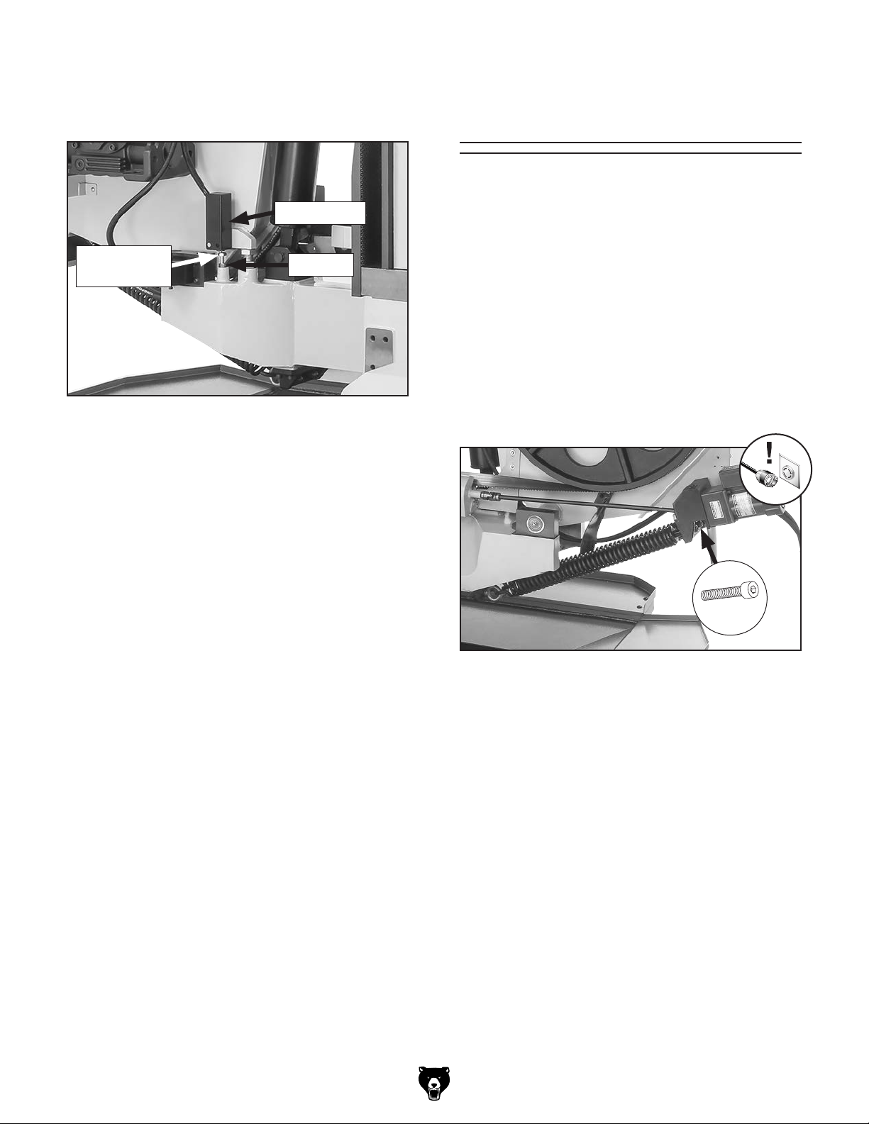
4. Loosen stop bolt jam nut, then adjust limit
switch stop bolt until head of stop bolt contacts limit switch (see
Limit Switch
Stop Bolt
Figure 114).
Limit Switch
Jam Nut
Adjusting
Headstock Spring
The spring under the headstock that controls
downward pressure of the headstock during cutting operations should have the correct tension.
The tension should only be adjusted if tension is
too loose, resulting in premature blade dulling or
crooked cuts. Consult the Troubleshooting section beginning on Page 60 to confirm this is the
source of the problem before adjusting.
Adjust cap screws shown in Figure 115 to
increase or decrease spring tension.
Figure 114. Limit switch stop bolt adjustment
components.
5. Tighten both jam nuts against base to pre-
vent stop bolts from loosening during use.
Tool Needed Qty
Hex Wrench 10mm ............................................ 1
x 2
Figure 115. Spring adjustment screw location.
Model G0887 (Mfd. Since 01/19)
-73 -
Page 83

Replacing/
Tensioning Drive
Belt
Remove (2) button head cap screws and flat
4.
washers to remove pulley cover bracket that
holds blade speed sensor so you can access
drive belt (see Figure 117).
To ensure optimum power transmission from the
motor to the bandsaw blade, the drive belt must
be in good condition (free from cracks, fraying,
and wear) and properly tensioned. After the first
16 hours of belt life, re-tension the belt, as it will
stretch and seat during this time.
Tools Needed Qty
Hex Wrench 3mm .............................................. 1
Assistant
Open-End Wrench 17mm
............................................................ 1
.................................. 1
Replacing Belt
If belt is cracked or worn, replace it before continuing operation.
To replace belt:
DISCONNECT MACHINE FROM POWER!
1.
2. Remove (5) button head cap screws and flat
washers to remove outer pulley cover (see
Figure 116).
Drive Belt
x 2
Figure 117. Pulley cover bracket location.
While an assistant holds motor, loosen (4)
5.
motor hex bolts (see Figure 118).
x 5
Outer
Pulley Cover
Figure 116. Outer pulley cover and securing
button head cap screws.
Adjust blade speed dial to maximum speed
3.
setting.
-74 -
x 4
Figure 118. Motor mounting bolts location.
6. Lower motor to release belt tension and
replace drive belt with new one.
Lift motor until there is proper belt tension
7.
(see Tensioning Belt on Page 75), then
tighten (4) motor hex bolts.
Install pulley cover bracket removed in Step
8.
4. Speed sensor should be 5mm away from
pulley.
Install outer pulley cover removed in Step 2.
9.
Model G0887 (Mfd. Since 01/19)
Page 84

Tensioning Belt
Drive belt should have a 1⁄4" of belt deflection.
To tension belt:
1. DISCONNECT MACHINE FROM POWER!
2. Remove (5) button head cap screws and flat
washers to remove outer pulley cover (see
Figure 119).
Adjust motor until there is 1⁄4" belt deflection
5.
when pressed in center with moderate pressure (see Figure 121).
Pulley
Deflection
1
⁄4"
Pulley
x 5
Outer
Pulley Cover
Figure 119. Outer pulley cover and securing
button head cap screws.
3. Adjust blade speed dial to maximum speed
setting.
4.
While an assistant holds motor, loosen (4)
motor hex bolts (see Figure 120).
Figure 121. Checking belt tension.
Tighten (4) motor hex bolts to secure tension.
6.
7. Install outer pulley cover.
x 4
Figure 120. Motor mounting bolts location.
Model G0887 (Mfd. Since 01/19)
-75-
Page 85
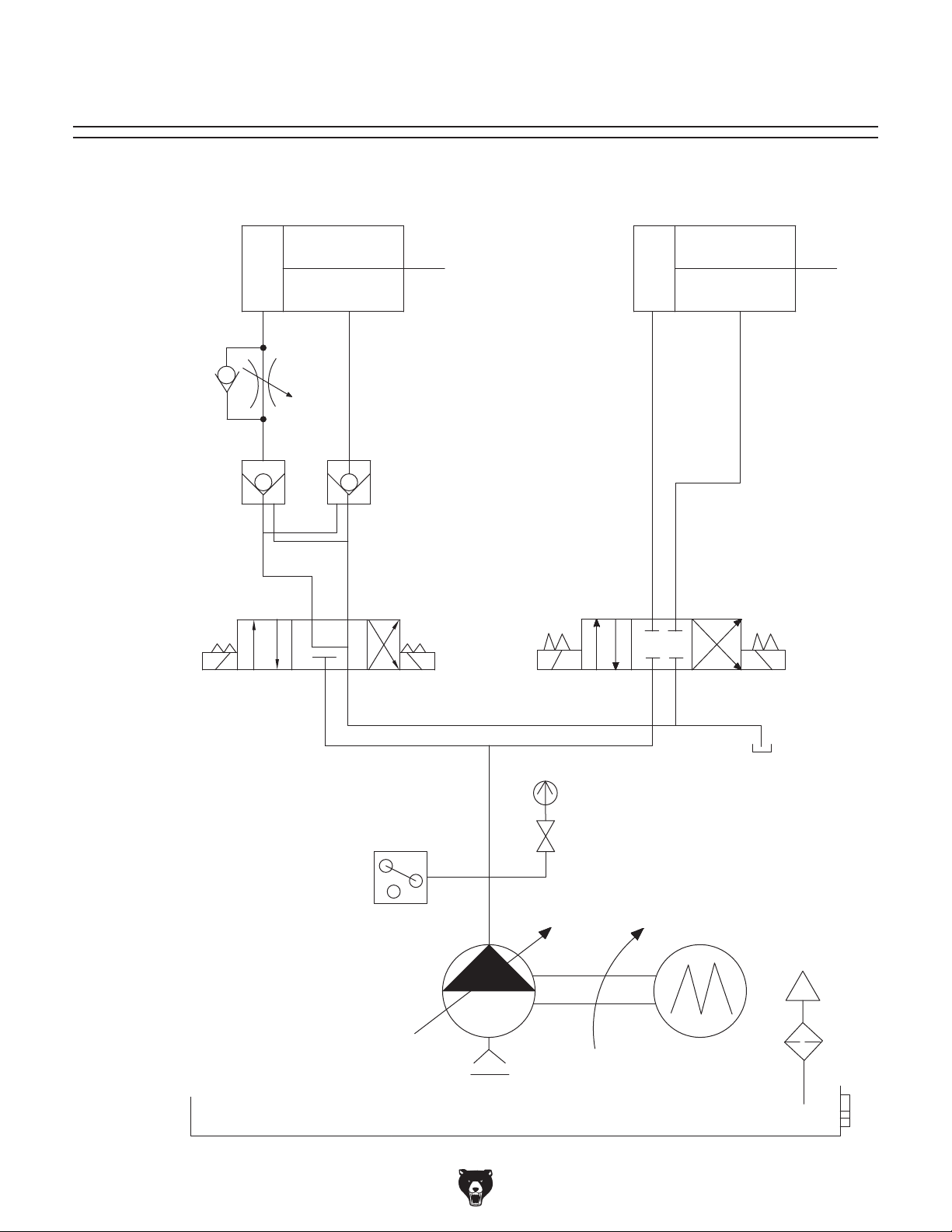
SECTION 8: HYDRAULICS
Flow Control
Valve Assembly
Hydraulic System Schematic
Saw Bow Cylinder Vise Jaw Cylinder
Pilot Check Valve
Saw Bow
Solenoid Valve
Pressure Sensor
Vise Jaw
Solenoid Valve
Pressure Gauge
Pressure Check Valve
Hydraulic Motor
Hydraulic Pump Assembly
-76-
Model G0887 (Mfd. Since 01/19)
Page 86

VISE JAW
HYDRAULIC
CYLINDER
Hydraulic System Diagram
FEED RATE
CONTROL
VALVE
HYDRAULIC
FLUID TANK
PUMP MOTOR
Copper
Tube
PUMP
SUCTION
FILTER
SAW BOW
HYDRAULIC
CYLINDER
MAX 498 PSI
PRESSURE
GAUGE
ASSEMBLY
PRESSURE
CHECK
VALVE
PRESSURE
RELIEF VALVE
HYDRAULIC MANIFOLDS
PRESSURE
SENSOR
PRESSURE
GAUGE
MAX 498 PSI
+
−
FLOW
CONTROL
VALVE
PILOT
CHECK
VALVE
SOL.ASOL.
Directional Valve
SOL.
A
Directional Valve
DSG-02-3C2-A2-N
DSG-02-3C4-A2-N
B
B
SOL.
OIL LEVEL
GAUGE
FILL
CAP
Model G0887 (Mfd. Since 01/19)
-77-
Page 87

These pages are current at the time of printing. However, in the spirit of improvement, we may make changes to the electrical systems of future machines. Compare the manufacture date of your machine to the one
number and manufacture date of your
machine before calling. This information can be found on the main machine label.
machine
SECTION 9: WIRING
stated in this manual, and study this section carefully.
If there are differences between your machine and what is shown in this section, call Technical Support at
(570) 546-9663 for assistance BEFORE making any changes to the wiring on your machine. An updated
wiring diagram may be available. Note: Please gather the serial
Wiring Safety Instructions
SHOCK HAZARD. Working on wiring that is con-
nected to a power source is extremely dangerous.
Touching electrified parts will result in personal
injury including but not limited to severe burns,
electrocution, or death. Disconnect the power
from the machine before servicing electrical components!
MODIFICATIONS. Modifying the wiring beyond
what is shown in the diagram may lead to unpredictable results, including serious injury or fire.
This includes the installation of unapproved aftermarket parts.
WIRE CONNECTIONS. All connections must
be tight to prevent wires from loosening during
machine operation. Double-check all wires disconnected or connected during any wiring task to
ensure tight connections.
CIRCUIT REQUIREMENTS. You MUST follow
the requirements at the beginning of this manual
when connecting your machine to a power source.
WIRE/COMPONENT DAMAGE. Damaged wires
or components increase the risk of serious personal injury, fire, or machine damage. If you notice
that any wires or components are damaged while
performing a wiring task, replace those wires or
components.
MOTOR WIRING. The motor wiring shown in
these diagrams is current at the time of printing
but may not match your machine. If you find this
to be the case, use the wiring diagram inside the
motor junction box.
CAPACITORS/INVERTERS. Some capacitors
and power inverters store an electrical charge for
up to 10 minutes after being disconnected from
the power source. To reduce the risk of being
shocked, wait at least this long before working on
capacitors.
EXPERIENCING DIFFICULTIES. If you are experiencing difficulties understanding the information
included in this section, contact our Technical
Support at (570) 546-9663.
The photos and diagrams
included in this section are
best viewed in color. You
can view these pages in
color at www.grizzly.com.
-78 -
Model G0887 (Mfd. Since 01/19)
Page 88

Component Locations
1
6
5
4
2
3
8
7
9
15
14
1
Control Panel (Page 85)
2
Hydraulic Unit (Page 84)
3
Home Proximity Sensor (Page 85)
4
Coolant Pump Motor (Page 87)
5
Blade Brush Motor (Page 87)
6
Blade Speed Sensor (Page 89)
7
Blade Motor (Page 86)
8
Blade Speed Meter (Page 89)
10
11
12
9
Headstock Lower Limit Switch (Page 89)
10
Rotary Potentiometer (Page 85)
11
Table Motor (Page 88)
12
Power Connection (Page 81)
13
Electrical Cabinet (Page 81–82)
14
Door Safety Limit Switch (Page 88)
15
Blade Tension Limit Switch (Page 88)
13
Model G0887 (Mfd. Since 01/19)
READ ELECTRICAL SAFETY
ON PAGE 78!
-79 -
Page 89

Electrical Overview
Rotary
Potentiometer
10
Home Proximity
Sensor
3
Power
Connection
12
Coolant Pump
Hydraulic Unit
2
9
Headstock Lower
Limit Switch
Blade Tension
Limit Switch
15
Motor
4
Control Panel
1
Electrical Cabinet
13
14
8
Door Safety
Limit Switch
Table Motor
11
Blade Motor
7
Blade Brush
Motor
5
-80-
Blade Speed
Meter
READ ELECTRICAL SAFETY
ON PAGE 78!
6
Blade Speed
Sensor
Model G0887 (Mfd. Since 01/19)
Page 90

Electrical Cabinet Wiring Diagram
ELECTRICAL CABINET
R12
S12
3L2
1L1
Power Switch
Disconnector
ABB OT25F3
4T2 6T3
2T1
L1 L3L2
RST
R1
R12
T12
S12
L1
L4
Circuit Board
RF500M 0904
0 220 0 24 0 12
0V 0V
L6
Transformer
LCE LCPIC-TBSW-100250
0V
30
29
28
27
17
16
15
L5
31
15G
See Pg. 82
0V
32
EMER-SW
PUMP-EV
WATER-EV
MOTOR-EV
AUTO-STOP
BROKE-SW
SAFE-SW
LS-DOWN
LS-CLIP
RUN-LAMP
COUNTER
220V
DOWN
UP
CLOSE
OPEN
+12
OV
OV
UB 2
GND
UB 1
GND
GND
GND
GND
GND
GND
PUMP
WATERMOTOR
L1
L3
L1
3L2
1L1
13NO
A1
5L3
5L3
Contactor
NHD C-06D10
1L1
3L2
5L3
Contactor
NHD C-06D10
13NO
29
4T2 6T3
2T1
OL Relay
TECO RHU-10/1K1
TRIP IND.
14
TEST
98 NO
97 NO
2T1
4T2
U2
A2
14NO
30
16
A
M
R
O
A
12
11.3
16
RESET
OFF
95 NC
96 NC
6T3
U1
W2
4T2 6T3
2T1
OL Relay
TECO RHU-10/1K1
TRIP IND.
14
TEST
98 NO
97 NO
2T1
V1
14NO
16
A
M
R
O
A
12
11.3
RESET
OFF
95 NC
96 NC
15G
6T3
4T2
17
W1
V2
15G
15G
L3
L4
L1
S1
T1
U3
A1
31
A2
32
U3
V3
W3
V3
L1
1L1 3L2
TECO CU-18
2T1
OL Relay
TECO RHU-10/16K1
TRIP IND.
TEST
97 NO
2T1
L3
L2
A2
A1
5L3
27
13NO
21NC
28
Contactor
22NC
14NO
4T2 6T3
16
A
M
14
R
O
A
12
11.3
RESET
OFF
95 NC
98 NO
96 NC
15G
6T3
4T2
W3
W2
U2 W1
U1
V2
L6
L5
24V
12V
15
W4
V4
WVU
U4
V1
See Pg. 82
W3U3
W2
T12
U2
V3
W1V1U1
WVU
V2
Variable Frequency Drive
ABB ACS150-03E-04A7-2
D15
D14
D13
D12
D11
COM
GND
-24V
-10V
GND
AI
SCR
To Control Panel
Hot
Hot
Hot
Ground
See Pg. 85
220 VAC
RST
L15-30 PLUG
(As Recommended)
W4
V4
U4
W4
V4
MAINS BRAKE MOTOR
U4
U1/L V1/N W1 BRK BRK U2 V2 W2
To
Table
Motor
See Pg. 88
To
Blade
Brush
Motor
See Pg. 87
To
Hydraulic
Motor
See Pg. 87
Braking Resistor
250W
To Control Panel
See Pg. 85
To
Coolant
Pump
Motor
See Pg. 87
To
Main
Motor
See Pg. 86
Model G0887 (Mfd. Since 01/19)
READ ELECTRICAL SAFETY
ON PAGE 78!
-81-
Page 91

Electrical Cabinet Wiring Diagram (Cont.)
ELECTRICAL CABINET
(Other Components Removed for Clarity)
38
RUN-LAMP
37
36
35
COUNTER
34
220V
33
PUMP
EMER-SW
PUMP-EV
WATER-EV
MOTOR-EV
AUTO-STOP
BROKE-SW
SAFE-SW
LS-DOWN
WATERMOTOR
26
DOWN
25
24
UP
23
22
CLOSE
21
20
OPEN
19
+12
18
18G
OV
OV
UB 2
14
GND
13
UB 1
GND
10
GND
9
GND
GND
GND
3
LS-CLIP
2
GND
8
7
6
5
4
1
18G
19
20
21
22
23
24
25
26
0V
220
L4
L1
L3
L4
8
7
6
5
4
3
2
1
1
2
3
4
Circuit Board
RF500M 0904
5
6
7
8
19
20
21
22
23
24
25
26
18
35
36
37
38
-82-
READ ELECTRICAL SAFETY
ON PAGE 78!
To Headstock Lower Limit Switch
To Door Safety Limit Switch
To Blade Tension Limit Switch
See Pg. 88
See Pg. 88
To Hydraulic Unit
See Pg. 84
To Blade Speed Meter
See Pg. 89
To Control Panel
Model G0887 (Mfd. Since 01/19)
See Pg. 89
See Pg. 85
Page 92

Figure 122. Electrical cabinet components and wiring connections.
Model G0887 (Mfd. Since 01/19)
READ ELECTRICAL SAFETY
ON PAGE 78!
-83-
Page 93

Hydraulic System Wiring Diagram
1
2
To Electrical
Cabinet
See Pg. 81–82
HYDRAULIC
MANIFOLD
+
−
2
21
1
SOL.ASOL.
Directional Valve
SOL.
2
A
Directional Valve
DSG-02-D4-A2-N
DSG-02-3C2-A2-N
B
B
SOL.
2
1
1
22
2
26
1
24
23
19
20
To Electrical
See Pg. 81–82
25
To Electrical
Cabinet
See Pg. 81–82
Cabinet
-84-
READ ELECTRICAL SAFETY
ON PAGE 78!
Figure 123. Hydraulic unit solenoids.
Model G0887 (Mfd. Since 01/19)
Page 94

Control Panel Wiring Diagram
See Pg. 88
To Table Motor
Home
Proximity
Sensor
12V
GND
LS-DN
LS-UP
12V
GND
LS-DN
LS-UP
FOR
COM
REV
GND
12V
A
B
Z
G
IN
5V
Up/Down, Left/Right
Schneider 2D-PA103
3 4
Headstock
Joystick
3 4
Electronic Counter
Gikoka EM 6R22
Auto Mode Button
NHD CB-10
NHD PL-BA9
NLB22-F
3 4
3 4
35
36
E-Stop Button
KEDU HY57B
1 2
18
18G
37
38
L4
4
Key Switch
NHD CB-10
NSS22-K
3
L3
CONTROL PANEL (viewed from behind)
Rotary
Potentiometer
Cosmos
RV24YN 20S
B103
1
3
2
To Electrical Cabinet
See Pg. 81–82
Figure 124. Home proximity switch.
Model G0887 (Mfd. Since 01/19)
Figure 125. Rotary potentiometer.
READ ELECTRICAL SAFETY
ON PAGE 78!
-85-
Page 95

Figure 126. Control panel components and wiring connections.
Motor Wiring Diagrams
MAIN MOTOR 220V
W2
U2 V2
Figure 127. Main motor junction box.
-86-
READ ELECTRICAL SAFETY
ON PAGE 78!
U1
V
U
V1
To Electrical Cabinet
See Pg. 81–82
Model G0887 (Mfd. Since 01/19)
W1
W
Page 96

Motor Wiring Diagrams (Cont.)
HYDRAULIC UNIT MOTOR 220V
W2
U2
W1U1
V2
V1
U1
V1
W1
To Electrical Cabinet
See Pg. 81–82
See Pg. 81–82
To Electrical Cabinet
Figure 129. Hydraulic unit motor junction box.
W2
V2
U2
4
6
1
2
3
5
COOLANT PUMP MOTOR 220V
Figure 130. Coolant pump motor junction box.
BLADE BRUSH MOTOR 220V
60W
4
3
6
2
5
1
U3
W3
V3
Figure 128. Blade brush motor junction box.
Model G0887 (Mfd. Since 01/19)
To Electrical Cabinet
See Pg. 81–82
READ ELECTRICAL SAFETY
ON PAGE 78!
-87-
Page 97

Motor Wiring Diagrams (Cont.)
TABLE MOTOR 220V
W2
U2 V2
U1
U4
V4 W4
W1
V1
To Control Panel
See Pg. 85
To Electrical Cabinet
Figure 131. Table motor junction box.
See Pg. 81–82
Other Electrical Component Wiring Diagrams
Door Safety
Limit Switch
CANLIE AZD-S11
1112
2324
5
6
To Electrical Cabinet
See Pg. 81–82
Blade Tension
Limit Switch
SHINOZAKI AZD-1001T
8
7
To Electrical Cabinet
See Pg. 81–82
Door Safety
Limit Switch
Figure 132. Door safety limit switch.
1112
2324
Blade Tension
Limit Switch
Figure 133. Blade tension limit switch.
-88-
READ ELECTRICAL SAFETY
ON PAGE 78!
Model G0887 (Mfd. Since 01/19)
Page 98

Other Electrical Component Wiring Diagrams
(Cont.)
Headstock Lower
Limit Switch
CANLIE AZD-1001T
3
2324
1112
4
Headstock Lower
To Electrical Cabinet
See Pg. 81–82
Blade Speed Meter
Circuit Board
151197
Figure 134. Headstock lower limit switch.
Limit Switch
Blade Speed
Meter
Blade Speed Sensor
YAWFONG DA1805PO
To Electrical Cabinet
See Pg. 81–82
Figure 135. Blade speed meter.
Blade Speed Sensor
L1
L4
Figure 136. Blade speed sensor.
Model G0887 (Mfd. Since 01/19)
READ ELECTRICAL SAFETY
ON PAGE 78!
-89-
Page 99

SECTION 10: PARTS
We do our best to stock replacement parts when possible, but we cannot guarantee that all parts shown
are available for purchase. Call (800) 523-4777 or visit www.grizzly.com/parts to check for availability.
90
Headstock
37
41
43
35
34
34
40
35
36
80-4
33
42
4
33
51
47
80-1
3
32
39
45
38
49
2
32
80-5
31
30
80-3
48
50
46
44
82
22
80
81
104
102
57
21
103
52
56
55
70
83
76
85
136
96
71
134
124
95
87
86
72
123
121
122
77
108
75
74
79
78
1
79
5
8
9
10
11
56
53
6
7
12
57
69
58
105
68
14
15
16
17
13
24
19
59
60
107
20
129
106
68
18
127
128
69
84
29
28
126
66
130
143
97
73
65
67
27
131
132
133
137
125
121
122
63
112
135
62
61
89
116
117
120
119
118
115
89
142
88
110-1
110-2
110-3
110-4
110-5
113
91
26
90
110
111
114
23
98
94
92
93
26
-90-
BUY PARTS ONLINE AT GRIZZLY.CO M!
Scan QR code to visit our Par ts Store.
98
94
100
101
99
109
140
141
139
25
138
Model G0887 (Mfd. Since 01/19)
64
54
Page 100

REF PART # DE SCRIP TIO N REF PART # DES CRIP TI ON
Headstock Parts List
1 P0887001 HEA DSTOCK FRAME 61 P0887061 DRIVE WHEE L
2 P0887002 BLADE TENSION ASSEMBLY COVER 62 P0887062 BEARING LOCK WASHER 60MM AW12
3 P0887003 FLA T WASHER 6MM 63 P0887063 BEARING LOCK NUT M60-2 AN12
4 P0887004 BUTTO N HD CAP SCR M6-1 X 12 64 P0887064 B UTTON HD CAP SCR M5 -. 8 X 1 2
5 P0887005 BLADE GUIDE BLOCK 65 P0887065 SPRING ANCHOR BLOCK
6 P0887006 FLAT WASHER 10MM 66 P0887066 LOCK WASHER 10MM
7 P0887007 CAP SCREW M10-1.5 X 60 67 P0887067 CAP SCREW M10-1.5 X 25
8 P0887008 STA ND-OFF ROUND MF 20, M12-1. 7 5 68 P0887068 FLAT WAS HER 6 MM
9 P0887009 BLADE GUIDE WHEEL 69 P0887069 CAP SCREW M6-1 X 15
10 P0887010 BALL BEARING 6205ZZ 70 P0887070 DRI VE WHEEL GEARBOX
11 P0887011 I NT RETA I NI NG RI NG 47MM 71 P0887071 LOCK WASHER 12MM
12 P0887012 CUP WASHER 12 X 35 X 8 72 P0887072 CAP SCREW M12-1.75 X 30
13 P0887013 LOCK WASHER 12MM 73 P0887073 SET SCREW M10-1.5 X 15
14 P0887014 CAP SCREW M12-1.75 X 25 74 P0887074 KEY 18 X 11 X 45
15 P0887015 FLAT WASHER 10MM 75 P0887075 KEY 7 X 8 X 60
16 P0887016 LOCK WASHER 10MM 76 P0887076 MOTOR PULLEY W/SPEED DI AL
17 P0887017 CAP SCREW M10-1.5 X 25 77 P0887077 V-BELT 1922V504
18 P0887018 BLADE GUI DE ARM GI B 78 P0887078 CLEVIS PIN SHAFT 20 X 111 HEADLESS
19 P0887019 CAP SCREW M5-.8 X 8 79 P0887079 EXT RETA I NI NG RI NG 2 0MM
20 P0887020 CAP SCREW M10-1.5 X 25 80 P0887080 MAIN MOTOR 5HP 220V 3-PH
21 P0887021 HINGE 80-1 P0887080-1 MOTOR FA N W/ COVE R
22 P0887022 BUTTON HD CAP SCR M6 -1 X 12 80-3 P0887080-3 MO TOR J UNCTIO N BOX
23 P0887023 WHEEL COVER 80-4 P0887080-4 BALL BEARING 6306ZZ (FRONT)
24 P0887024 BLADE GUI DE ARM BRACKET (LEFT) 80-5 P0887080-5 BALL BEARING 6306ZZ (REAR)
25 P0887025 BLADE 232" X 1-1/2" 4-TPI HOOK 81 P0887081 LOCK WASHER 10MM
26 P0887026 HYDRAULI C S TRUT 82 P0887082 HEX BOLT M10-1. 5 X 35
27 P0887027 BLADE GUI DE ARM SCALE 83 P0887083 KEY 8 X 7 X 40
28 P0887028 BUTTON HD CAP SCR M5 -.8 X 10 84 P0887084 BLADE GUI DE ARM BRACKET (RIGHT)
29 P0887029 THREADED SHAFT 40 X 56 X 312.5 85 P0887085 PULLEY COVER (INNER)
30 P0887030 TENSI ON/TRACKI NG SLIDE BLOCK 86 P0887086 FLAT WA SHE R 5MM
31 P0887031 SOLID PIN 16 X 90MM 87 P0887087 BUTTON HD CAP SCR M5 -.8 X 12
32 P0887032 TRACKI NG A DJ USTMENT B RACK ET 88 P0887088 PULLEY COVER (OUTER)
33 P0887033 TENSI ON/ TRACKI NG GI B 89 P0887089 FLAT WAS HER 5 MM
34 P0887034 LOCK WASHER 10MM 90 P0887090 BUTTON HD CAP S CR M5- . 8 X 1 2
35 P0887035 CAP SCREW M10-1.5 X 65 91 P0887091 STRUT BRACKET ( RI GHT)
36 P0887036 IDLER WHEEL SHAFT 92 P0887092 STRUT BRACK ET ( LEFT)
37 P0887037 SET SCREW M12-1.75 X 20 93 P0887093 CAP SCREW M6-1 X 20
38 P0887038 TENSI ON LEADSCREW 94 P0887094 LOCK WASHER 6MM
39 P0887039 TENSI ON BUSHI NG 52 X 58 X 80 95 P0887095 PULLEY COVER BRACKET
40 P0887040 TENSI ON LIMIT BRACKET 96 P0887096 FLAT WAS HER 5 MM
41 P0887041 HEX NUT M8- 1. 25 97 P0887097 BUTTON HD CAP SCR M5 -.8 X 12
42 P0887042 HEX BOLT M8-1.25 X 100 98 P0887098 HEX NUT M6 -1
43 P0887043 SPACER 20. 5 X 50 X 40 99 P0887099 FLA T WAS HER 6MM
44 P0887044 BLADE TENSION GAUGE 100 P0887100 B UTTON HD CA P SCR M6-1 X 1 2
45 P0887045 SHAFT COLLAR M8-1.25 101 P0887101 CAP SCREW M6-1 X 25
46 P0887046 SET SCREW M8-1.25 X 12 102 P0887102 FLAT WAS HER 6 MM
47 P0887047 HANDWHEEL HUB 78D X 20B X M12-1. 75 103 P0887103 BUTTON HD CAP SCR M6 -1 X 12
48 P0887048 SET SCREW M8-1.25 X 12 104 P0887104 SPEED INDI CATOR FACEPLATE
49 P0887049 FIXED HANDLE 25 X 140, M12-1.75 X 18 105 P0887105 BLADE DRIP FLAP BRACKET
50 P0887050 THRUST BEARING 51204 106 P0887106 BLADE DRI P FLAP
51 P0887051 DISC SPRI NG 20.5 X 50 107 P0887107 BLADE DRIP FLAP BACKI NG
52 P0887052 BLADE SPEED I NDICATOR COVER 108 P0887108 GEARBOX PULLEY
53 P0887053 BANJO BOLT M12-1. 75 X 20 109 P0887109 B UTTON HD CAP SCR M6 -1 X 10
54 P0887054 BLADE BRUSH SHAFT COVER 110 P0887110 BLADE BRUSH MOTOR 60W 220V 3-PH
55 P0887055 IDLER WHEEL 110-1 P0887110-1 MOTOR FAN CO VE R
56 P0887056 TAPERED ROLLER BEARING 32009 110-2 P0887110-2 MOTOR FAN
57 P0887057 BEARING COVER 110-3 P0887110-3 MOTOR J UNCTI O N BOX
58 P0887058 BEARING LOCK WASHER 45MM AW09 110-4 P0887110-4 BALL BEARING 6200ZZ (FRONT)
59 P0887059 BEARING LOCK NUT M45-1.5 AN09 110-5 P0887110-5 BALL BEARI NG 6000ZZ (REAR)
60 P0887060 GREASE FI TTING 1/8-NPT STRAIGHT 111 P0887111 BLADE BRUSH GEARBOX
Model G0887 (Mfd. Since 01/19)
BUY PARTS ONLINE AT GRIZZLY.CO M!
Scan QR code to visit our Par ts Store.
-91-
 Loading...