

Page 1

MODEL G0886
12" X 14" 3 HP AUTO
METAL-CUTTING BANDSAW
OWNER'S MANUAL
(For models manufactured since 01/19)
COPYRIGHT © APRIL, 2019 BY GRIZZLY INDUSTRIAL, INC.
WARNING : NO PORTION OF THIS MANUAL MAY BE REPRODUCED IN ANY SHAPE
OR FORM WITHOUT THE WRITTEN APPROVAL OF GRIZZLY INDUSTRIAL, INC.
#ES20255 PRINTED IN TA I WAN
V1. 0 4.19
Page 2

This manual provides critical safety instructions on the proper setup,
operation, maintenance, and service of this machine/tool. Save this
document, refer to it often, and use it to instruct other operators.
Failure to read, understand and follow the instructions in this manual
may result in fire or serious personal injury—including amputation,
electrocution, or death.
The owner of this machine/tool is solely responsible for its safe use.
This responsibility includes but is not limited to proper installation in
a safe environment, personnel training and usage authorization,
proper inspection and maintenance, manual availability and comprehension, application of safety devices, cutting/sanding/grinding tool
integrity, and the usage of personal protective equipment.
The manufacturer will not be held liable for injury or property damage
from negligence, improper training, machine modifications or misuse.
Some dust created by power sanding, sawing, grinding, drilling, and
other construction activities contains chemicals known to the State
of California to cause cancer, birth defects or other reproductive
harm. Some examples of these chemicals are:
• Lead from lead-based paints.
• Crystalline silica from bricks, cement and other masonry products.
• Arsenic and chromium from chemically-treated lumber.
Your risk from these exposures varies, depending on how often you
do this type of work. To reduce your exposure to these chemicals:
Work in a well ventilated area, and work with approved safety equipment, such as those dust masks that are specially designed to filter
out microscopic particles.
Page 3

Table of Contents
INTRODUCTION ............................................... 2
Contact Info.................................................... 2
Manual Accuracy ........................................... 2
Identification ................................................... 3
Controls & Components ................................. 4
Machine Data Sheet ...................................... 6
SECTION 1: SAFETY ....................................... 8
Safety Instructions for Machinery .................. 8
Additional Safety for Horizontal Metal
Bandsaws .................................................... 10
SECTION 2: POWER SUPPLY ...................... 11
SECTION 3: SETUP ....................................... 13
Needed for Setup ......................................... 13
Unpacking .................................................... 14
Inventory ...................................................... 14
Hardware Recognition Chart ....................... 15
Cleanup ........................................................ 16
Site Considerations ...................................... 17
Lifting & Placing ........................................... 18
Anchoring to Floor ....................................... 19
Assembly ..................................................... 20
Lubricating Machine ..................................... 21
Test Run ...................................................... 21
Recommended Adjustments ........................ 24
Disabling & Locking Switch.......................... 24
SECTION 4: OPERATIONS ........................... 25
Operation Overview ..................................... 25
Blade Selection ............................................ 26
Changing Blades.......................................... 28
Tensioning Blade ......................................... 30
Blade Breakage ........................................... 31
Blade Care & Break-In ................................. 31
Changing Blade Speed ................................ 32
Blade Speed Chart ...................................... 33
Chip Inspection Chart .................................. 34
Using Vise .................................................... 35
Blade Guides ............................................... 35
Setting Headstock Height ............................ 36
Setting Blade Feed Rate.............................. 36
Feed System ................................................ 37
Proximity Sensor .......................................... 37
Coolant ......................................................... 39
Using Coolant System ................................. 39
Operation Tips ............................................. 40
Workpiece Inspection................................... 40
SECTION 5: ACCESSORIES ......................... 41
SECTION 6: MAINTENANCE ......................... 42
Schedule ...................................................... 42
Cleaning & Protecting .................................. 42
Lubrication ................................................... 43
Hydraulic System ......................................... 46
Coolant System............................................ 48
Inspecting V-Belt .......................................... 49
Machine Storage .......................................... 50
SECTION 7: SERVICE ................................... 51
Troubleshooting ........................................... 51
Adjusting Lower Limit Stop Bolt ................... 54
Adjusting Blade Tracking ............................. 54
Adjusting Blade Brush ................................. 55
Adjusting Blade Guides ............................... 56
Squaring Blade to Table .............................. 58
SECTION 8: WIRING ...................................... 59
Wiring Safety Instructions ............................ 59
Electrical Schematics ................................... 60
Electrical Photos .......................................... 63
SECTION 9: PARTS ....................................... 65
Base ............................................................. 65
Headstock .................................................... 67
Gearbox ....................................................... 70
Feed System ................................................ 71
Electrical ...................................................... 73
Labels & Cosmetics ..................................... 75
WARRANTY & RETURNS ............................. 77
Page 4
We stand behind our machines! If you have questions or need help, contact us with the information
below. Before contacting, make sure you get the
serial number
machine ID label. This will help us help you faster.
We want your feedback on this manual. What did
you like about it? Where could it be improved?
Please take a few minutes to give us feedback.
Email: manuals@grizzly.com
We are proud to provide a high-quality owner’s
manual with your new machine!
We
instructions, specifications, drawings, and photographs
in this manual. Sometimes we make mistakes, but
our policy of continuous improvement also means
that
you receive is
slightly different than shown in the manual
If you find this to be the case, and the difference
between the manual and machine leaves you
confused or unsure about something
check our
website for an updated version. W
current
manuals and
on our web-
site at
Alternatively, you can call our Technical Support
for help. Before calling, make sure you write down
the
from
the machine ID label (see below). This information
is required for us to provide proper tech support,
and it helps us determine if updated documentation is available for your machine.
INTRODUCTION
Contact Info
and manufacture date from the
Grizzly Technical Support
1815 W. Battlefield
Springfield, MO 65807
Phone: (570) 546-9663
Email: techsupport@grizzly.com
Grizzly Documentation Manager
P.O. Box 2069
Bellingham, WA 98227-2069
Manual Accuracy
made every effort to be exact with the
sometimes the machine
.
,
e post
manual updates for free
www.grizzly.com.
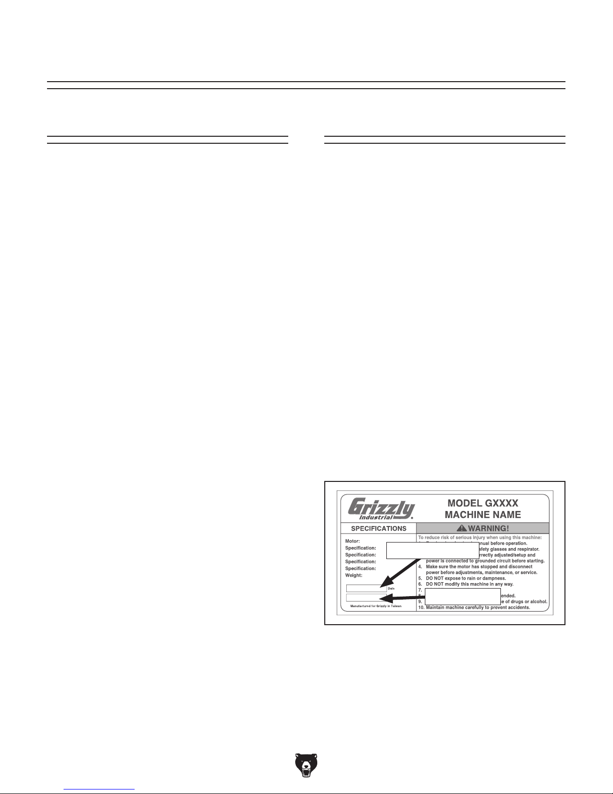
Manufacture Date and Serial Number
Manufacture Date
Serial Number
-2-
Model G0886 (Mfd. Since 01/19)
Page 5
Identification
To reduce your risk of
serious injury, read this
entire manual BEFORE
Become familiar with the names and locations of the controls and features shown below to better understand
the instructions in this manual.
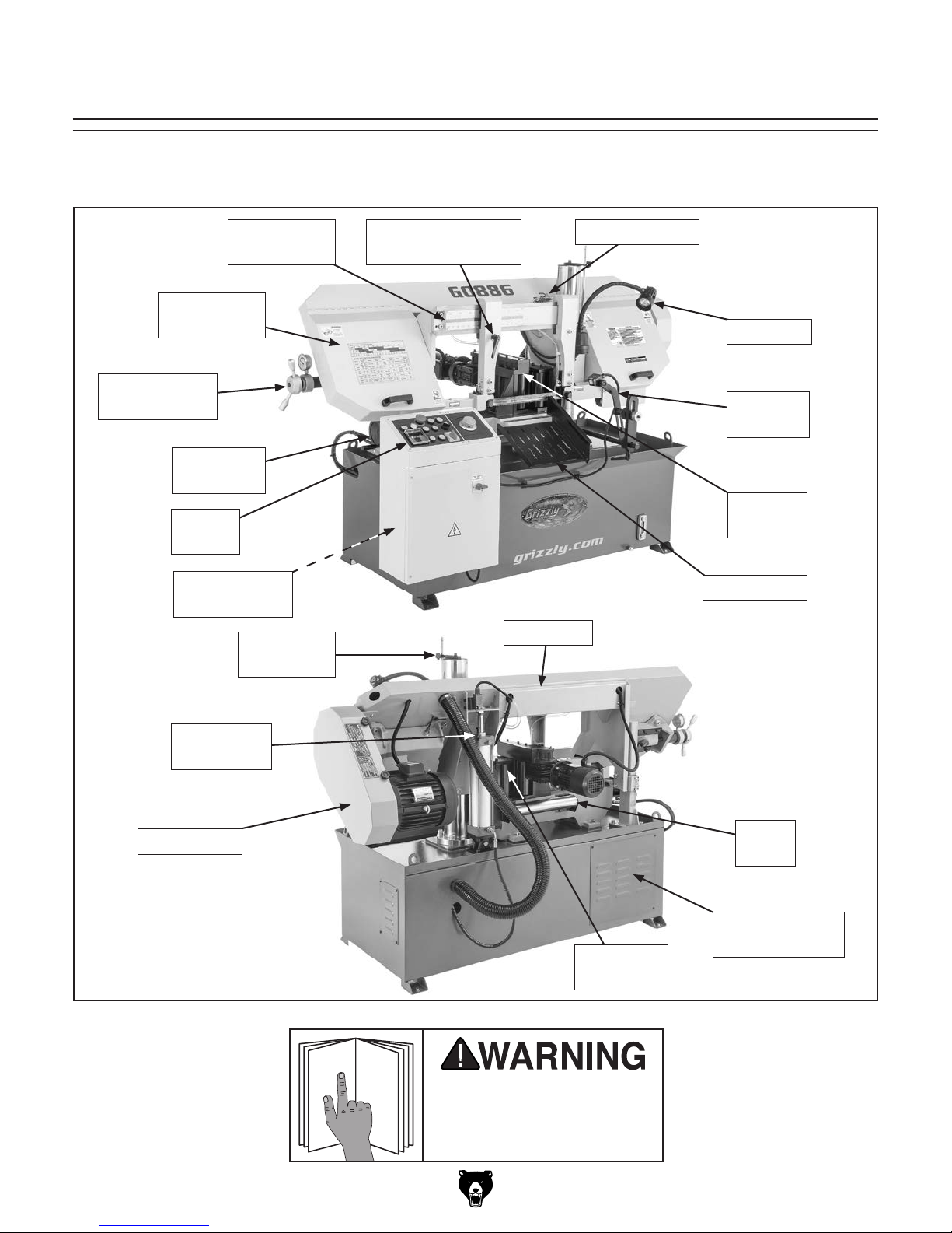
Front View
Wheel Cover
Blade Tension
Handwheel
Handwheel
Control
Coolant Pump
Blade Guide
Scale
(1 of 2)
Vise
Panel
Access Panel
Headstock
Height Stop
Coolant ValvesBlade Guide Arm
Adjustment Handle
Worklamp
Proximity
Sensor
Movable
Vise Jaw
Cutoff Chute
Headstock
Rear View
Lower Limit
Stop Bolt
Pulley Cover
Model G0886 (Mfd. Since 01/19)
Infeed
Roller
Hydraulic Pump
Access Panel
Fixed Vise
Jaw
using machine.
-3-
Page 6
Controls &
To reduce your risk of
serious injury, read this
entire manual BEFORE
B. Power Lamp: Illuminates when master power
switch is turned ON.
Components
using machine.
Refer to the following figures and descriptions to
become familiar with the basic controls and components of this machine. Understanding these
items and how they work will help you understand
the rest of the manual and minimize your risk of
injury when operating this machine.
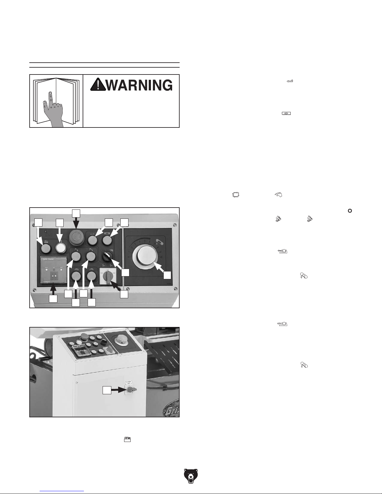
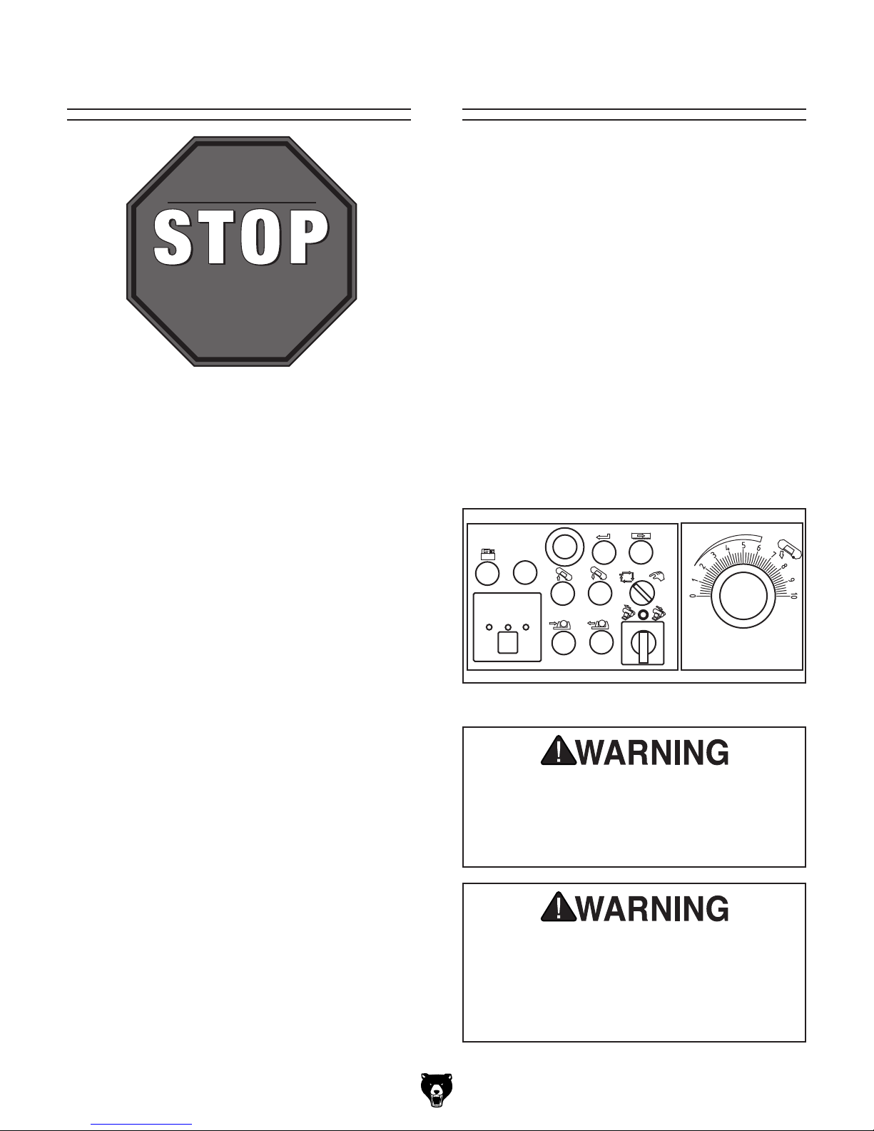
Control Panel
C
A
DBE
C. Emergency Stop Button: Stops all machine
functions. Twist clockwise to reset.
D. Feed System Button
ON when machine is in Manual operation
mode.
E. Blade Start Button
ON and starts saw blade. For button to work,
hydraulic pump button (A) must be pressed,
headstock must be raised, and vise close
button (K) must be pressed.
F. Blade Feed Rate Dial: Controls rate at which
blade feeds into workpiece.
G. Operation Mode Switch: Selects between
Auto
H. Feed Roller Switch: Turns feed motor OFF
and ON when FWD
FWD must be selected for Auto operation
mode.
or Manual operation mode.
: Turns feed motor
: Turns main motor
or REV are selected.
G
J
L
M
Figure 1. Model G0886 control panel.
Figure 2. Master power switch location.
A. Hydraulic Pump Button : Turns hydrau-
lic pump ON. Must be pressed for other
bandsaw controls to function.
-4-
I
K
H
N
I. Vise Open Button
vise to release workpiece after cut(s).
F
J. Lower Headstock Button
lowers headstock at rate determined by blade
feed rate dial (F). Continues lowering blade
until lower limit switch is activated or button
is released.
K. Vise Close Button
vise to lock workpiece during cut(s). Button
must be pressed for blade start button (E) to
function.
L. Raise Headstock Button
raises headstock. Continues raising blade
until upper limit switch is activated or button
is released.
M. Digital Counter: Sets number of consecutive
cuts machine will perform. The number of
completed cuts is displayed. Push RESET to
clear display and reset counter.
N. Master Power ON/OFF Switch: Turns
incoming power ON and OFF.
Model G0886 (Mfd. Since 01/19)
: Hydraulically opens
: Hydraulically
: Hydraulically closes
: Hydraulically
Page 7
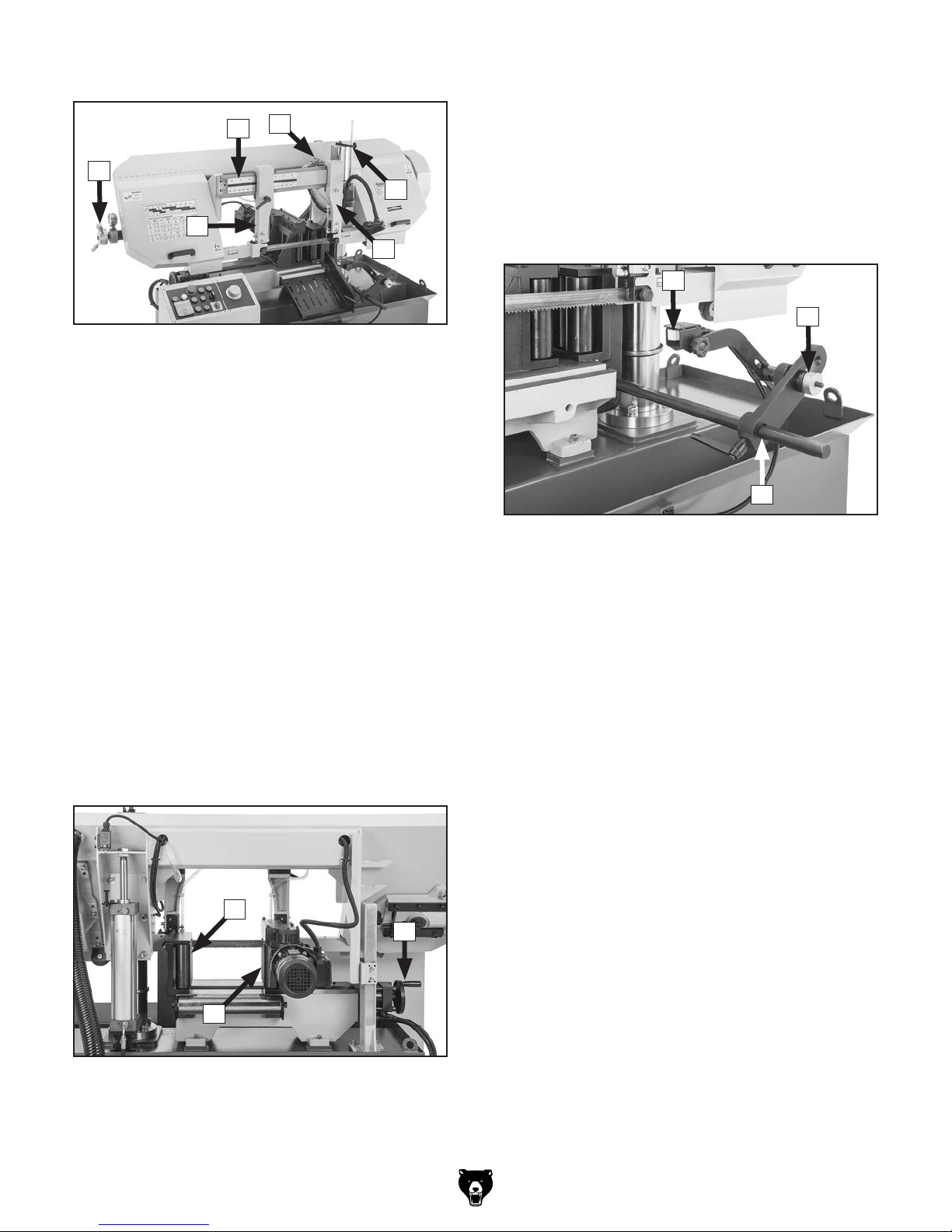
Headstock
U. Movable Vise Jaw: Holds workpiece during
cutting operations. Jaw is positioned manu-
R
P
ally and locked hydraulically. Has motorized
rollers that feed material into cutting position.
O
S
Q
Q
Figure 3. Headstock controls and components.
O. Blade Tension Handwheel w/Gauge:
Increases or decreases blade tension. Gauge
ensures accurate tensioning of blade.
P. Blade Guide Scale: Displays position of left
blade guide arm relative to workpiece.
Q. Blade Guide Arms: Hold blade guides that
support bandsaw blade. Left arm is adjustable; right arm is fixed. Place left arm as
close to workpiece as possible during cutting
to prevent blade from twisting.
R. Coolant Valves: Control flow of coolant
through blade guides and onto blade.
V. Vise Handwheel: Adjusts position of mov-
able vise jaw relative to fixed vise jaw.
Proximity Sensor
W
Y
X
Figure 5. Proximity sensor components.
W. Proximity Sensor Head: Detects the pres-
ence (within
nation with proximity sensor bracket and bar,
functions as a work stop during automated
and repetitive cutting operations.
1
⁄4") of metal materials. In combi-
S. Headstock Height Stop: Adjustable rod and
bracket that controls upper travel of headstock by triggering a limit switch.
Vise Table
T
V
U
Figure 4. Vise table controls and components.
T. Fixed Vise Jaw: Helps hold workpiece dur-
ing cutting operations. Has rollers that help
feed material into cutting position.
X. Proximity Sensor Bracket and Bar:
Supports and positions the proximity sensor
head.
Y. Proximity Sensor Adjustment Knob:
Moves proximity sensor bracket and head
laterally in fine increments for precision cutting operations.
Model G0886 (Mfd. Since 01/19)
-5-
Page 8

Machine Data Sheet
MACHINE DATA
SHEET
Customer Service #: (570) 546-9663 · To Order Call: (800) 523-4777 · Fax #: (800) 438-5901
MODEL G0886 12" X 14" 3 HP 3‐PHASE AUTO METAL‐
CUTTING BANDSAW
Product Dimensions:
Weight............................................................................................................................................................ 1630 lbs.
Width (side-to-side) x Depth (front-to-back) x Height........................................................................... 83 x 43 x 55 in.
Footprint (Length x Width)............................................................................................................................ 56 x 28 in.
Shipping Dimensions:
Type.......................................................................................................................................................... Wood Crate
Content........................................................................................................................................................... Machine
Weight............................................................................................................................................................ 1800 lbs.
Length x Width x Height....................................................................................................................... 85 x 48 x 62 in.
Must Ship Upright................................................................................................................................................... Yes
Electrical:
Power Requirement................................................................................................................... 220V, 3-Phase, 60 Hz
Full-Load Current Rating................................................................................................................................... 13.32A
Minimum Circuit Size.............................................................................................................................................. 20A
Connection Type....................................................................................................................................... Cord & Plug
Power Cord Included.............................................................................................................................................. Yes
Power Cord Length............................................................................................................................................... 12 ft.
Power Cord Gauge......................................................................................................................................... 12 AWG
Plug Included........................................................................................................................................................... No
Recommended Plug Type................................................................................................................................. L15-20
Switch Type.............................................................................................................. Control Panel w/Magnetic Switch
Motors:
Main
Horsepower................................................................................................................................................ 3 HP
Phase.................................................................................................................................................... 3-Phase
Amps.............................................................................................................................................................. 8A
Speed................................................................................................................................................ 1735 RPM
Type........................................................................................................................................... TEFC Induction
Power Transfer ........................................................................................................................................ V-Belt
Bearings........................................................................................................ Sealed & Permanently Lubricated
Feed
Horsepower............................................................................................................................................. 1/8 HP
Phase.................................................................................................................................................... 3-Phase
Amps......................................................................................................................................................... 1.46A
Speed................................................................................................................................................ 1620 RPM
Type........................................................................................................................................... TEFC Induction
Power Transfer .......................................................................................................................................... Gear
Bearings........................................................................................................ Sealed & Permanently Lubricated
-6-
Model G0886 (Mfd. Since 01/19)
Page 9

Hydraulic Pump
Horsepower................................................................................................................................................ 1 HP
Phase.................................................................................................................................................... 3-Phase
Amps........................................................................................................................................................... 3.6A
Speed................................................................................................................................................ 1420 RPM
Type........................................................................................................................................... TEFC Induction
Power Transfer ......................................................................................................................................... Direct
Bearings........................................................................................................ Sealed & Permanently Lubricated
Coolant Pump
Horsepower............................................................................................................................................. 1/8 HP
Phase.................................................................................................................................................... 3-Phase
Amps......................................................................................................................................................... 0.26A
Speed................................................................................................................................................ 3600 RPM
Type........................................................................................................................................... TEFC Induction
Power Transfer ......................................................................................................................................... Direct
Bearings........................................................................................................ Sealed & Permanently Lubricated
Main Specifications:
Operation Info
Blade Speeds................................................................................................................. 92, 161, 236, 338 FPM
Std. Blade Length.............................................................................................................................. 155-1/2 in.
Blade Length Range.......................................................................................................... 155-1/4 - 155-3/4 in.
Cutting Capacities
Vise Jaw Depth.......................................................................................................................................... 14 in.
Vise Jaw Height................................................................................................................................. 6-11/16 in.
Max. Capacity Rectangular Height at 90 Deg................................................................................. 11-13/16 in.
Max. Capacity Rectangular Width at 90 Deg............................................................................................. 14 in.
Max. Capacity Round at 90 Deg...................................................................................................... 11-13/16 in.
Construction
Table.................................................................................................................................................... Cast Iron
Upper Wheel........................................................................................................................................ Cast Iron
Lower Wheel........................................................................................................................................ Cast Iron
Body........................................................................................................................................................... Steel
Stand.......................................................................................................................................................... Steel
Paint Type/Finish...................................................................................................................................... Epoxy
Other
Wheel Size.......................................................................................................................................... 15-3/4 in.
Blade Guides Upper..................................................................................................................... Carbide Steel
Blade Guides Lower.............................................................................................. Carbide Steel, Ball Bearings
Coolant Capacity.................................................................................................................................... 6.5 gal.
Hydraulic Capacity..................................................................................................................................... 16 qt.
Other Specifications:
Country of Origin .............................................................................................................................................. Taiwan
Warranty ........................................................................................................................................................... 1 Year
Approximate Assembly & Setup Time ........................................................................................................ 1-1/2 Hour
Serial Number Location ................................................................................................................... Machine ID Label
ISO 9001 Factory .................................................................................................................................................. Yes
Certified by a Nationally Recognized Testing Laboratory (NRTL) .......................................................................... No
Model G0886 (Mfd. Since 01/19)
-7-
Page 10

SECTION 1: SAFETY
For Your Own Safety, Read Instruction
Manual Before Operating This Machine
The purpose of safety symbols is to attract your attention to possible hazardous conditions.
This manual uses a series of symbols and signal words intended to convey the level of importance of the safety messages. The progression of symbols is described below. Remember that
safety messages by themselves do not eliminate danger and are not a substitute for proper
accident prevention measures. Always use common sense and good judgment.
Indicates an imminently hazardous situation which, if not avoided,
WILL result in death or serious injury.
Indicates a potentially hazardous situation which, if not avoided,
COULD result in death or serious injury.
Indicates a potentially hazardous situation which, if not avoided,
MAY result in minor or moderate injury. It may also be used to alert
against unsafe practices.
Alerts the user to useful information about proper operation of the
NOTICE
machine to avoid machine damage.
Safety Instructions for Machinery
OWNER’S MANUAL. Read and understand this
owner’s manual BEFORE using machine.
TRAINED OPERATORS ONLY. Untrained operators have a higher risk of being hurt or killed.
Only allow trained/supervised people to use this
machine. When machine is not being used, disconnect power, remove switch keys, or lock-out
machine to prevent unauthorized use—especially
around children. Make your workshop kid proof!
DANGEROUS ENVIRONMENTS. Do not use
machinery in areas that are wet, cluttered, or have
poor lighting. Operating machinery in these areas
greatly increases the risk of accidents and injury.
MENTAL ALERTNESS REQUIRED. Full mental
alertness is required for safe operation of machinery. Never operate under the influence of drugs or
alcohol, when tired, or when distracted.
ELECTRICAL EQUIPMENT INJURY RISKS.
You can be shocked, burned, or killed by touching
live electrical components or improperly grounded
machinery. To reduce this risk, only allow qualified
service personnel to do electrical installation or
repair work, and always disconnect power before
accessing or exposing electrical equipment.
DISCONNECT POWER FIRST.
nect machine from power supply BEFORE making adjustments, changing tooling, or servicing
machine. This prevents an injury risk from unintended startup or contact with live electrical components.
EYE PROTECTION. Always wear ANSI-approved
safety glasses or a face shield when operating or
observing machinery to reduce the risk of eye
injury or blindness from flying particles. Everyday
eyeglasses are NOT approved safety glasses.
Always discon-
-8-
Model G0886 (Mfd. Since 01/19)
Page 11

WEARING PROPER APPAREL. Do not wear
clothing, apparel or jewelry that can become
entangled in moving parts. Always tie back or
cover long hair. Wear non-slip footwear to reduce
risk of slipping and losing control or accidentally
contacting cutting tool or moving parts.
HAZARDOUS DUST. Dust created by machinery
operations may cause cancer, birth defects, or
long-term respiratory damage. Be aware of dust
hazards associated with each workpiece material. Always wear a NIOSH-approved respirator to
reduce your risk.
HEARING PROTECTION. Always wear hearing protection when operating or observing loud
machinery. Extended exposure to this noise
without hearing protection can cause permanent
hearing loss.
REMOVE ADJUSTING TOOLS. Tools left on
machinery can become dangerous projectiles
upon startup. Never leave chuck keys, wrenches,
or any other tools on machine. Always verify
removal before starting!
USE CORRECT TOOL FOR THE JOB. Only use
this tool for its intended purpose—do not force
it or an attachment to do a job for which it was
not designed. Never make unapproved modifications—modifying tool or using it differently than
intended may result in malfunction or mechanical
failure that can lead to personal injury or death!
AWKWARD POSITIONS. Keep proper footing
and balance at all times when operating machine.
Do not overreach! Avoid awkward hand positions
that make workpiece control difficult or increase
the risk of accidental injury.
CHILDREN & BYSTANDERS. Keep children and
bystanders at a safe distance from the work area.
Stop using machine if they become a distraction.
GUARDS & COVERS. Guards and covers reduce
accidental contact with moving parts or flying
debris. Make sure they are properly installed,
undamaged, and working correctly BEFORE
operating machine.
FORCING MACHINERY. Do not force machine.
It will do the job safer and better at the rate for
which it was designed.
NEVER STAND ON MACHINE. Serious injury
may occur if machine is tipped or if the cutting
tool is unintentionally contacted.
STABLE MACHINE. Unexpected movement during operation greatly increases risk of injury or
loss of control. Before starting, verify machine is
stable and mobile base (if used) is locked.
USE RECOMMENDED ACCESSORIES. Consult
this owner’s manual or the manufacturer for recommended accessories. Using improper accessories will increase the risk of serious injury.
UNATTENDED OPERATION. To reduce the
risk of accidental injury, turn machine OFF and
ensure all moving parts completely stop before
walking away. Never leave machine running
while unattended.
MAINTAIN WITH CARE. Follow all maintenance
instructions and lubrication schedules to keep
machine in good working condition. A machine
that is improperly maintained could malfunction,
leading to serious personal injury or death.
DAMAGED PARTS. Regularly inspect machine
for damaged, loose, or mis-adjusted parts—or
any condition that could affect safe operation.
Immediately repair/replace BEFORE operating
machine. For your own safety, DO NOT operate
machine with damaged parts!
MAINTAIN POWER CORDS. When disconnecting cord-connected machines from power, grab
and pull the plug—NOT the cord. Pulling the cord
may damage the wires inside. Do not handle
cord/plug with wet hands. Avoid cord damage by
keeping it away from heated surfaces, high traffic
areas, harsh chemicals, and wet/damp locations.
EXPERIENCING DIFFICULTIES. If at any time
you experience difficulties performing the intended operation, stop using the machine! Contact our
Technical Support at (570) 546-9663.
Model G0886 (Mfd. Since 01/19)
-9-
Page 12

Additional Safety for
Horizontal Metal Bandsaws
Serious injury or death can occur from getting fingers, hair, or clothing entangled in rotating or
moving parts or making direct contact with the moving blade. To minimize risk of injury, anyone
operating this machine MUST completely heed hazards and warnings below.
BLADE CONDITION. Do not operate with dull,
cracked, or badly worn blade. Inspect blades for
cracks and missing teeth before each use.
HAND PLACEMENT. Never position hands or fingers in line with the cut or under bandsaw headstock while lowering or operating. Hands could be
cut or crushed.
ENTANGLEMENT HAZARDS. Do not operate
this saw without blade guard in place. Loose
clothing, jewelry, long hair and work gloves can be
drawn into working parts.
BLADE REPLACEMENT. When replacing
blades, disconnect the machine from power, wear
gloves to protect hands and safety glasses to
protect eyes.
WORKPIECE HANDLING. Always properly support workpiece with table, vise, or some type of
support fixture. Always secure workpiece in vise
before cutting. Never hold the workpiece with your
hands during a cut.
UNSTABLE WORKPIECES. Avoid cutting workpieces that cannot be properly supported or
clamped in a vise or jig, because they can unexpectedly move while cutting and draw the operator’s hands into the blade causing serious personal injury. Examples are chains, cables, round
or oblong-shaped workpieces, and those with
internal or built-in moving or rotating parts, etc.
FIRE HAZARD. Use EXTREME CAUTION if cutting magnesium. Using the wrong cutting fluid
could lead to chip fire and possible explosion.
CUTTING FLUID SAFETY. Cutting fluids are
poisonous. Always follow manufacturer’s cuttingfluid safety instructions. Pay particular attention
to contact, contamination, inhalation, storage and
disposal warnings. Spilled cutting fluid invites slipping hazards.
HOT SURFACES. Contact with hot surfaces from
machine components, ejections of hot chips,
swarf, and the workpiece itself can cause burns.
Like all machinery there is potential danger
when operating this machine. Accidents
are frequently caused by lack of familiarity
or failure to pay attention. Use this machine
with respect and caution to decrease the
risk of operator injury. If normal safety precautions are overlooked or ignored, serious personal injury may occur.
-10 -
No list of safety guidelines can be complete. Every shop environment is different.
Always consider safety first, as it applies
to your individual working conditions. Use
this and other machinery with caution and
respect. Failure to do so could result in
serious personal injury, damage to equipment, or poor work results.
Model G0886 (Mfd. Since 01/19)
Page 13

Before installing the machine, consider the availability and proximity of the required power supply
circuit. If an existing circuit does not meet the
requirements for this machine, a new circuit must
be installed. To minimize the risk of electrocution,
fire, or equipment damage, installation work and
electrical wiring must be done by an electrician or
qualified service personnel in accordance with all
applicable codes and standards.
or equipment damage
may occur if machine is
not properly grounded
and connected to power
The full-load current rating is the amperage a
machine draws at 100% of the rated output power.
On machines with multiple motors, this is the
amperage drawn by the largest motor or sum of all
motors and electrical devices that might operate
at one time during normal operations.
The full-load current is not the maximum amount
of amps that the machine will draw. If the machine
is overloaded, it will draw additional amps beyond
the full-load rating.
If the machine is overloaded for a sufficient length
of time, damage, overheating, or fire may result—
especially if connected to an undersized circuit.
To reduce the risk of these hazards, avoid overloading the machine during operation and make
sure it is connected to a power supply circuit that
meets the specified circuit requirements.
For your own safety and protection of
Note: Circuit requirements in this manual apply to
a dedicated circuit—where only one machine will
be running on the circuit at a time. If machine will
be connected to a shared circuit where multiple
machines may be running at the same time, consult an electrician or qualified service personnel to
ensure circuit is properly sized for safe operation.
This machine is prewired to operate on a power
supply circuit that has a verified ground and meets
the following requirements:
A power supply circuit includes all electrical
equipment between the breaker box or fuse panel
in the building and the machine. The power supply circuit used for this machine must be sized to
safely handle the full-load current drawn from the
machine for an extended period of time. (If this
machine is connected to a circuit protected by
fuses, use a time delay fuse marked D.)
Power Supply
SECTION 2: POWER SUPPLY
Availability
Electrocution, fire, shock,
supply.
Full-Load Current Rating
Circuit Requirements for 220V
Nominal Voltage .........20 8V, 220V, 230V, 2 4 0V
Cycle .......................................................... 60 Hz
Phase .................................................... 3-Phase
Power Supply Circuit ......................... 20 Amps
Plug/Receptacle ......................... NEMA L15 -20
Cord ........“S ”-Typ e , 4-Wire, 12 AWG, 30 0 VAC
Full-Load Current Rating at 220V ..13.32 Amps
Model G0886 (Mfd. Since 01/19)
property, consult an electrician if you are
unsure about wiring practices or electrical
codes in your area.
-11-
Page 14

We do not recommend using an extension cord
with this machine.
cord, only use it if absolutely necessary and only
on a temporary basis.
Extension cords cause voltage drop, which can
damage electrical components and shorten motor
life. Voltage drop increases as the extension cord
size gets longer and the gauge size gets smaller
(higher gauge numbers indicate smaller sizes).
Any extension cord used with this machine must
be in good condition and contain a ground wire
and matching plug/receptacle. Additionally, it must
meet the following size requirements:
Improper connection of the equipment-grounding
wire can result in a risk of electric shock. The
wire with green insulation (with or without yellow
stripes) is the equipment-grounding wire. If repair
or replacement of the power cord or plug is necessary, do not connect the equipment-grounding
wire to a live (current carrying) terminal.
Check with a qualified electrician or service personnel if you do not understand these grounding
requirements, or if you are in doubt about whether
the tool is properly grounded. If you ever notice
that a cord or plug is damaged or worn, disconnect it from power, and immediately replace it with
a new one.
Serious injury could occur if you connect
process. DO NOT connect to power until
Grounding Instructions
This machine MUST be grounded. In the event
of certain malfunctions or breakdowns, grounding
reduces the risk of electric shock by providing a
path of least resistance for electric current.
The power cord and plug specified under “Circuit
Requirements for 220V”
has an equipment-grounding wire and a grounding prong. The plug must only be inserted into
a matching receptacle (outlet) that is properly
installed and grounded in accordance with all
local codes and ordinances (see figure below).
No adapter should be used with plug. If
plug does not fit available receptacle, or if
process. DO NOT connect to power until
on the previous page
GROUNDED
L15-20 RECEPTACLE
Grounding Prong
is Hooked
L15-20
PLUG
Serious injury could occur if you connect
machine to power before completing setup
instructed later in this manual.
Current Carrying Prongs
Figure 6. Typical L15-20 plug and receptacle.
machine to power before completing setup
instructed later in this manual.
machine must be reconnected for use on a
different type of circuit, reconnection must
be performed by an electrician or qualified
service personnel, and it must comply with
all local codes and ordinances.
-12-
Extension Cords
If you must use an extension
Minimum Gauge Size ...........................12 AWG
Maximum Length (Shorter is Better).......50 ft.
Model G0886 (Mfd. Since 01/19)
Page 15

SECTION 3: SETUP
Needed for Setup
This machine presents
serious injury hazards
to untrained users. Read
through this entire manual to become familiar with
the controls and operations before starting the
machine!
Wear safety glasses during
the entire setup process!
The following are needed to complete the setup
process:
• For Lifting and Moving:
— Two additional people
— A forklift or other power lifting equipment
rated for at least 2250 lbs.
— Four lifting straps rated for at least
2250 lbs. each
— Four heavy-duty lifting hooks or shackles
rated for at least 2250 lbs.
• For Power Connection:
— A power source that meets minimum
circuit requirements for machine (review
Power Supply on Page 11 for details)
— An electrician or qualified service person-
nel to ensure a safe and code-compliant
connection to power source
This is an extremely heavy machine! Serious
personal injury or death may occur if safe
lifting and moving methods are not followed. To be safe, you will need assistance
and power lifting equipment when moving
shipping crate and removing machine from
crate. Seek assistance from a professional
rigger if you are unsure about your abilities or maximum load ratings of your lifting
equipment.
• For Assembly:
— Safety glasses for each person
— Leather gloves for each person
— Disposable Shop Rags
— Cleaner/degreaser (see Page 16)
— Quality metal protectant/lubricant
— Hammer & Pry Bar
— Open-End or Socket Wrench 14mm
— Hex Wrench 5mm
— Piece of metal stock
Model G0886 (Mfd. Since 01/19)
-13-
Page 16

This machine was carefully packaged for safe
transport. When unpacking, separate all enclosed
items from packaging materials and inspect them
for shipping damage.
,
please
IMPORTANT:
you are completely satisfied with the machine and
have resolved any issues between Grizzly or the
shipping agent. You MUST have the original pack-
aging to file a freight claim. It is also extremely
helpful if you need to return your machine later.
Unpacking
The following is a list of items shipped with your
machine. Before beginning setup, lay these items
out and inventory them.
If any non-proprietary parts are missing (e.g. a
nut or a washer), we will gladly replace them; or
for the sake of expediency, replacements can be
obtained at your local hardware store.
If items are damaged
call us immediately at (570) 546-9663.
Save all packaging materials until
Inventory
Box Inventory (Figure 7) Qty
A. Dr ip Tr a y ..................................................... 1
B. Cutoff Chute ............................................... 1
C. Proximity Sensor Bracket Assembly .......... 1
D. Proximity Sensor Bar .................................. 1
E. Lock Handle (Proximity Sensor) ................. 1
F. Knob Bolt (Proximity Sensor) ..................... 1
A
C
Figure 7. Box inventory.
B
D
F
E
NOTICE
If you cannot find an item on this list, carefully check around/inside the machine and
packaging materials. Often, these items get
lost in packaging materials while unpacking or they are pre-installed at the factory.
-14-
Model G0886 (Mfd. Since 01/19)
Page 17
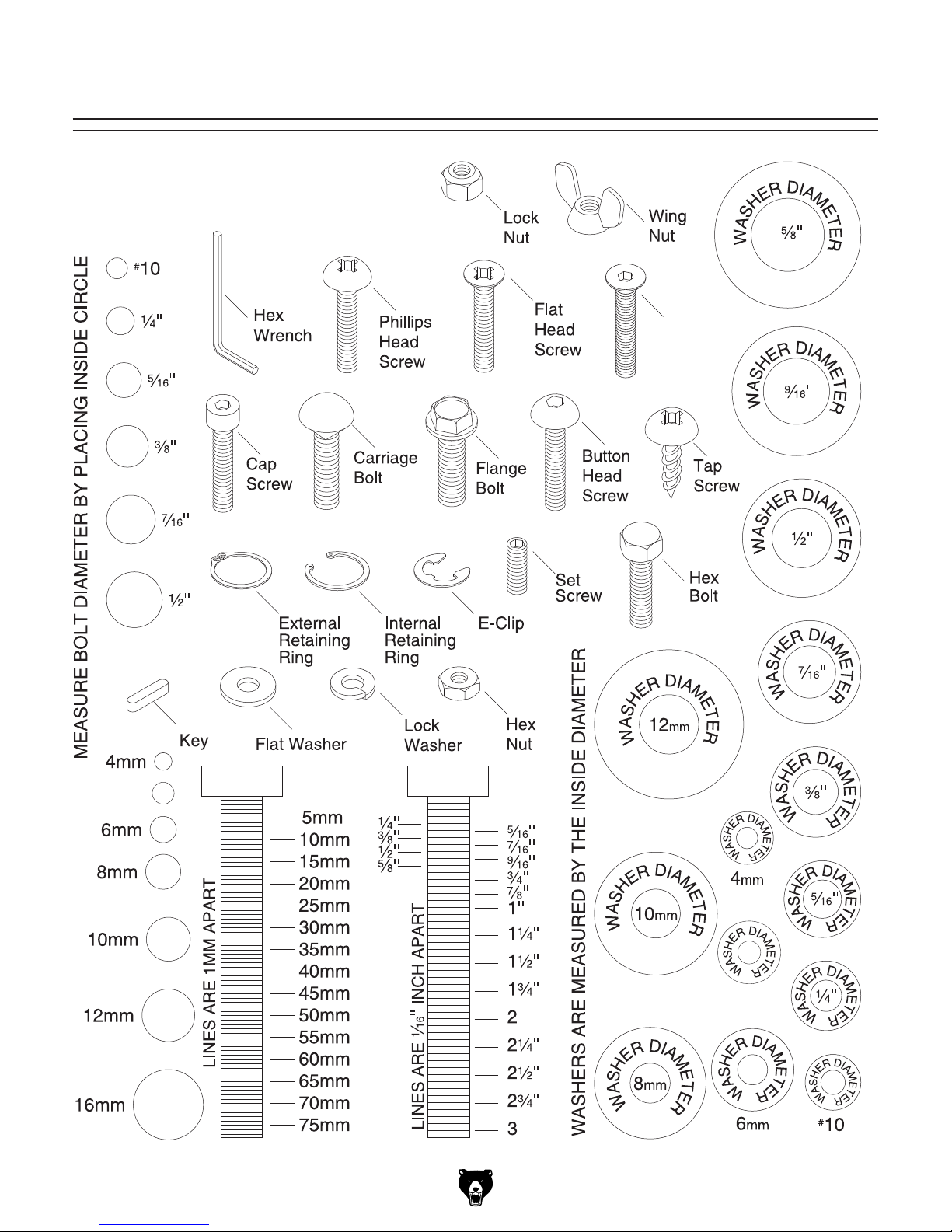
Hardware Recognition Chart
USE THIS CHART TO MATCH UP
HARDWARE DURING THE INVENTORY
AND ASSEMBLY PROCESS.
Flat
Head
Cap
Screw
5mm
Model G0886 (Mfd. Since 01/19)
5mm
-15-
Page 18
Cleanup
The unpainted surfaces of your machine are
coated with a heavy-duty rust preventative that
prevents corrosion during shipment and storage.
This rust preventative works extremely well, but it
will take a little time to clean.
Be patient and do a thorough job cleaning your
machine. The time you spend doing this now will
give you a better appreciation for the proper care
of your machine's unpainted surfaces.
There are many ways to remove this rust preventative, but the following steps work well in a wide
variety of situations. Always follow the manufacturer’s instructions with any cleaning product you
use and make sure you work in a well-ventilated
area to minimize exposure to toxic fumes.
Before cleaning, gather the following:
• Disposable rags
• Cleaner/degreaser (WD•40 works well)
• Safety glasses & disposable gloves
• Plastic paint scraper (optional)
Basic steps for removing rust preventative:
1.
2.
3.
4.
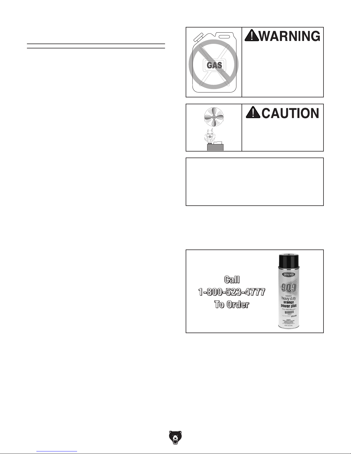
Many cleaning solvents
work in a well-ventilated
Cleanup
Gasoline and petroleum
products have low flash
points and can explode
or cause fire if used to
clean machinery. Avo id
using these products
to clean machinery.
Put on safety glasses.
Coat the rust preventative with a liberal
amount of cleaner/degreaser, then let it soak
for 5–10 minutes.
Wipe off the surfaces. If your cleaner/degreas-
er is effective, the rust preventative will wipe
off easily. If you have a plastic paint scraper,
scrape off as much as you can first, then wipe
off the rest with the rag.
are toxic if inhaled. Only
area.
NOTICE
Avoid harsh solvents like acetone or brake
parts cleaner that may damage painted surfaces. Always test on a small, inconspicuous location first.
T23692—Orange Power Degreaser
A great product for removing the waxy shipping grease from the non-painted parts of the
machine during clean up.
Repeat Steps 2–3 as necessary until clean,
then coat all unpainted surfaces with a quality
metal protectant to prevent rust.
-16 -
Figure 8. T23692 Orange Power Degreaser.
Model G0886 (Mfd. Since 01/19)
Page 19
Site Considerations
Weight Load
Refer to the
of your machine. Make sure that the surface upon
which the machine is placed will bear the weight
of the machine, additional equipment that may be
installed on the machine, and the heaviest workpiece that will be used. Additionally, consider the
weight of the operator and any dynamic loading
that may occur when operating the machine.
Space Allocation
Consider the largest size of workpiece that will
be processed through this machine and provide
enough space around the machine for adequate
operator material handling or the installation of
auxiliary equipment. With permanent installations,
leave enough space around the machine to open
or remove doors/covers as required by the maintenance and service described in this manual.
See below for required space allocation.
Physical Environment
Extreme conditions for this type of machinery are
Place this machine near an existing power source.
other hazards. Make sure to leave enough space
Shadows, glare, or strobe effects that may distract
or impede the operator must be eliminated.
Machine Data Sheet for the weight
Children or untrained people
may be seriously injured by
this machine. Only install in an
access restricted location.
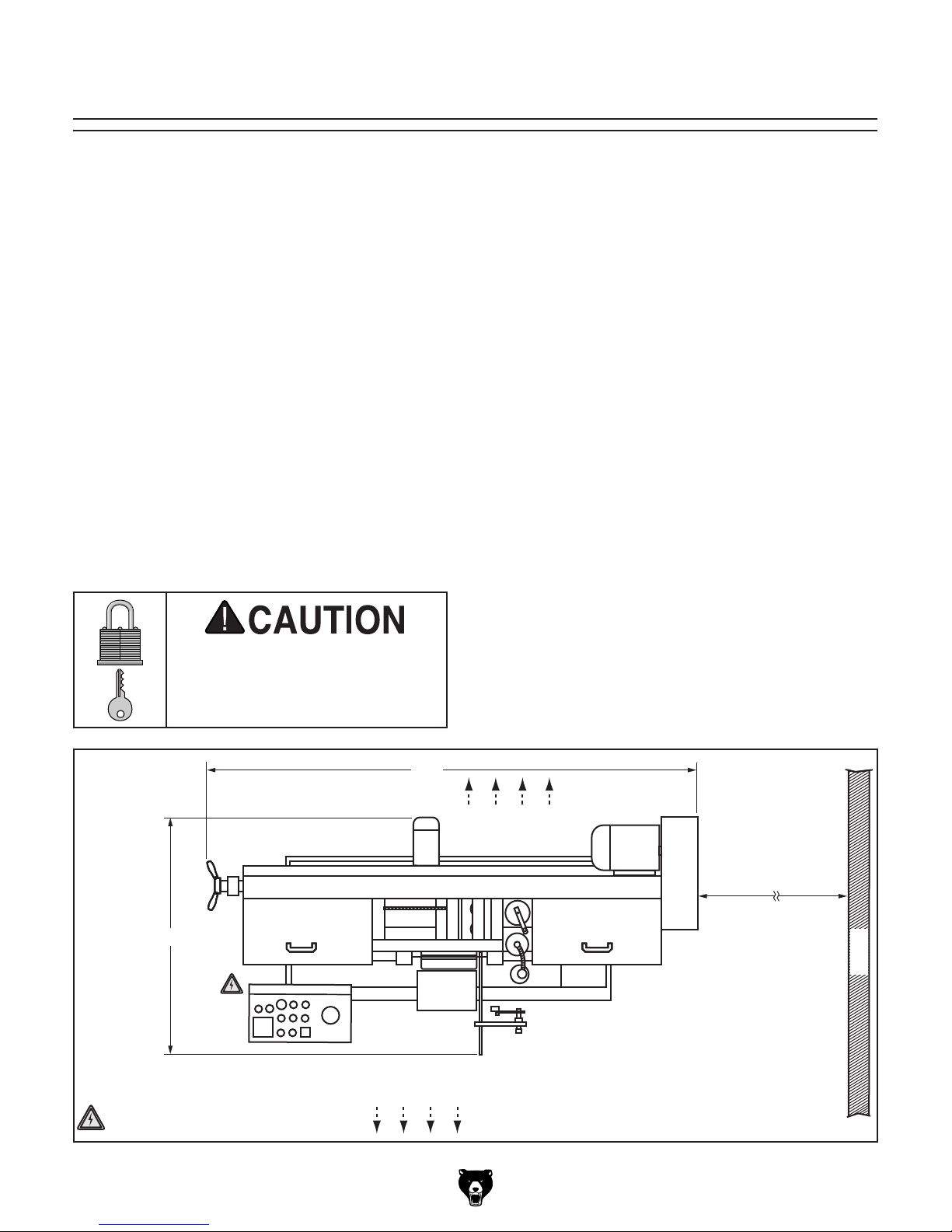
43"
Unobstructed
83"
Keep Area
The physical environment where the machine is
operated is important for safe operation and longevity of machine components. For best results,
operate this machine in a dry environment that is
free from excessive moisture, hazardous chemicals, airborne abrasives, or extreme conditions.
generally those where the ambient temperature
range exceeds 41°–104°F; the relative humidity
range exceeds 20%–95% (non-condensing); or
the environment is subject to vibration, shocks,
or bumps.
Electrical Installation
Make sure all power cords are protected from
traffic, material handling, moisture, chemicals, or
around machine to disconnect power supply or
apply a lockout/tagout device, if required.
Lighting
Lighting around the machine must be adequate
enough that operations can be performed safely.
Keep Area
Unobstructed
Min. 30"
for Maintenance
Wall
= Electrical Connection
Model G0886 (Mfd. Since 01/19)
Figure 9. Minimum working clearances.
-17-
Page 20
Lifting & Placing
To lift and place machine:
1. Move machine over its prepared location
while still inside shipping crate.
2. Remove top and sides of shipping crate, then
place small items aside in safe location.
Note: Do not destroy shipping crate and
packaging until after Test Run.
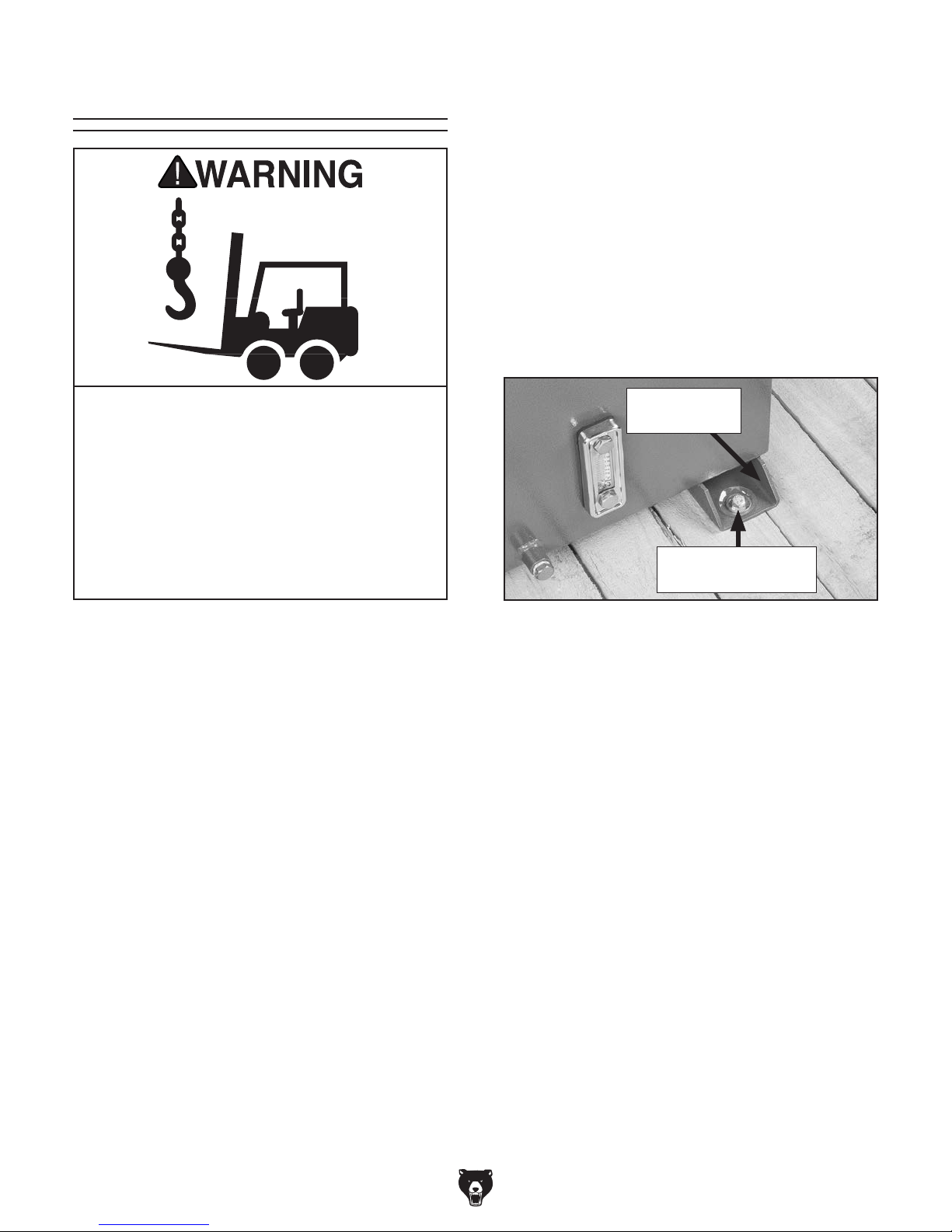
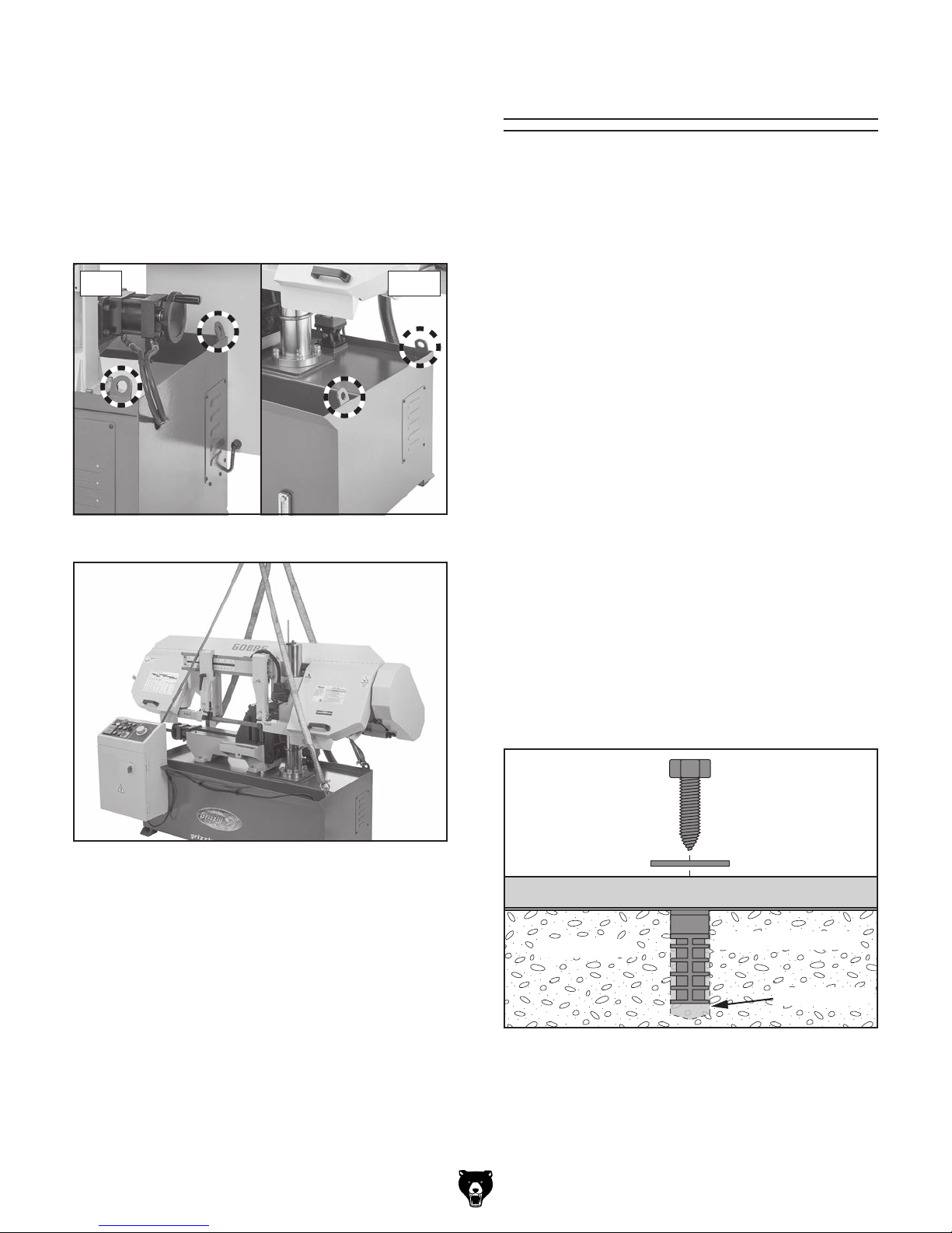
3. Remove (4) lag screws and flat washers that secure machine to shipping pallet
(see Figure 10).
This is an extremely heavy machine! Serious
personal injury or death may occur if safe
lifting and moving methods are not followed. To be safe, you will need assistance
and power lifting equipment when moving
shipping crate and removing machine from
crate. Seek assistance from a professional
rigger if you are unsure about your abilities or maximum load ratings of your lifting
equipment.
DO NOT attempt to lift or move machine without
using proper lifting equipment (such as a forklift)
and assistance from other people. Each piece of
lifting equipment must be rated for at least 2250
lbs. to support dynamic loads that may be applied
while lifting.
Review the Power Supply section beginning on
Page 11, then prepare a permanent location for
the machine.
Machine Foot
(1 of 4)
Lag Screw and Flat
Washer (1 of 4)
Figure 10. Machine secured to shipping pallet.
IMPORTANT: Make sure prepared location is
clean, flat, and reasonably level.
-18-
Model G0886 (Mfd. Since 01/19)
Page 21
4. Secure lifting straps to (4) hoist rings on
Anchoring machinery to the floor prevents tipping
or shifting and reduces vibration that may occur
during operation, resulting in a machine that runs
slightly quieter and feels more solid.
If the machine will be installed in a commercial or
workplace setting, or if it is permanently connected (hardwired) to the power supply, local codes
may require that it be anchored to the floor.
If not required by any local codes, fastening the
machine to the floor is an optional step. If you
choose not to do this with your machine, we recommend placing it on machine mounts, as these
provide an easy method for leveling and they have
vibration-absorbing pads.
Lag shield anchors with lag screws (see below)
are a popular way to anchor machinery to a concrete floor, because the anchors sit flush with the
floor surface, making it easy to unbolt and move
the machine later, if needed. However, anytime
local codes apply, you MUST follow the anchoring
methodology specified by the code.
machine (see Figure 11) with heavy-duty lifting hooks or shackles, and attach straps to
lifting equipment (see Figure 12).
Note: Hoist rings are positioned on machine
to balance weight of machine when using
four lifting straps of equal length.
Left Right
Figure 11. Location of hoist rings.
Anchoring to Floor
Number of Mounting Holes ............................ 4
Diameter of Mounting Hardware .................
3
⁄8"
Figure 12. Lifting machine with lifting slings.
5. Raise machine a couple of inches and check
balance of load. Have two other people carefully steady machine to help prevent it from
swinging while lifting.
6. Raise machine enough to clear shipping pallet and carefully remove pallet.
7. Slowly lower machine into position.
8. Anchor machine to floor (refer to Anchoring
to Floor).
Model G0886 (Mfd. Since 01/19)
Anchoring to Concrete Floors
Lag Screw
Flat Washer
Machine Base
Concrete
Figure 13. Popular method for anchoring
machinery to a concrete floor.
Lag Shield Anchor
Drilled Hole
-19 -
Page 22
Assembly
The machine must be fully assembled before it
can be operated. Before beginning the assembly
process, refer to
all
goes smoothly, first clean any
ered or coated in heavy-duty rust preventative (if
applicable).
Needed for Setup and gather
listed items. To ensure the assembly process
parts that are cov-
3. Attach proximity sensor to proximity sensor
bracket assembly with pre-installed knob
bolt, as shown in Figure 16.
Proximity
Sensor Bracket
Assembly
With the exception of the proximity sensor, drip
tray, and cutoff chute, the Model G0886 comes
fully assembled from the factory.
To assemble machine:
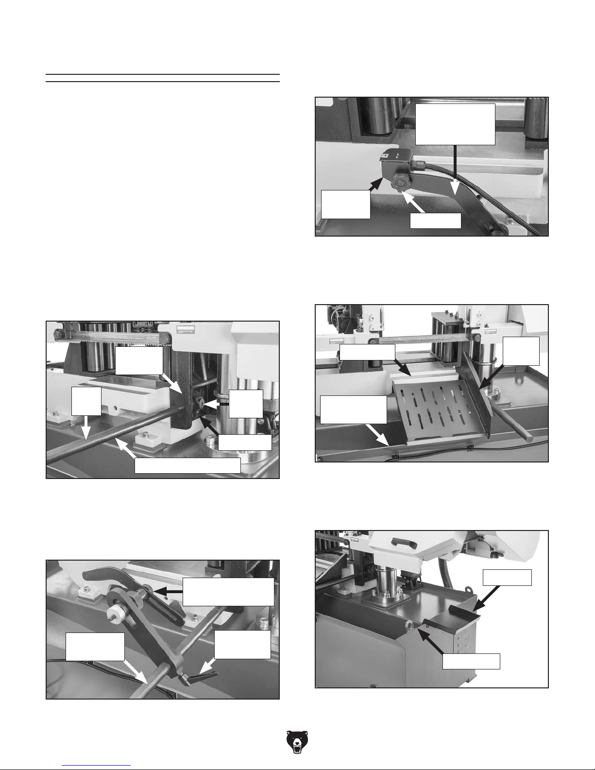
1. Slide proximity sensor bar into hole in fixed
vise jaw with flat edge on bar upward, as
shown in Figure 14, then tighten set screws.
Fixed
Vise Jaw
Flat
Edge
Proximity Sensor Bar
Set
Screw
Set Screw
Proximity
Sensor
Knob Bolt
Figure 16. Proximity sensor attached.
4. Position cutoff chute between vise table and
angled base flange, as shown in Figure 17.
Vise Table
Angled Base
Flange
Figure 17. Cutoff chute positioned.
Cutoff
Chute
Figure 14. Proximity sensor bar attached.
2. Slide proximity sensor bracket assembly onto
proximity sensor bar, as shown in Figure 15,
then tighten adjustable handle.
Proximity Sensor
Bracket Assembly
Proximity
Sensor Bar
Figure 15. Proximity sensor bracket attached.
-20-
Adjustable
Handle
5. Position drip tray on base edge, as shown in
Figure 18.
Drip Tray
Base Edge
Figure 18. Drip tray positioned.
Model G0886 (Mfd. Since 01/19)
Page 23
Once assembly is complete, test run the machine
to ensure it is properly connected to power and
safety components are functioning correctly.
If you find an unusual problem during the test run,
immediately stop the machine, disconnect it from
power, and fix the problem BEFORE operating the
machine again. The
table in the
SERVICE section of this manual can help.
DO NOT start machine until all preceding
setup instructions have been performed.
Operating an improperly set up machine
Serious injury or death can result from
Lubricating Machine
GEARBOX MUST
BE FILLED WITH OIL!
Test Run
Test Run
MACHINE MAY NOT BE
SHIPPED WITH OIL!
Requires Oil
Before Operation
or Warranty Will
Be Void.
The gearbox must have the proper amount of
gear oil in it before the machine can be operated.
Refer to the Lubrication section, beginning on
Page 43, for checking and adding gear oil.
IMPORTANT: Damage caused to the bearings,
and gears from running the machine without
gear oil in the gearbox will not be covered under
warranty.
Troubleshooting
The Test Run verifies the following: 1) all motors
power up and run correctly, 2) the hydraulic
system runs correctly, 3) 3-phase power supply
polarity is correct, (4) the Emergency Stop button
safety feature works correctly, and (5) the lower
limit switch safety feature works correctly.
Refer to Figure 19 during Tes t Run. Each control
has an alphabetical callout for identification.
C
D E
B
A
J
L
G
F
M
N
I
K
H
Model G0886 (Mfd. Since 01/19)
Figure 19. G0886 control panel.
using this machine BEFORE understanding
its controls and related safety information.
DO NOT operate, or allow others to operate,
machine until the information is understood.
may result in malfunction or unexpected results that can lead to serious injury,
death, or machine/property damage.
-21-
Page 24
To test run machine:
1. Read and follow safety instructions at begin-
ning of manual, take all required safety precautions, and make sure all previous setup/
assembly steps in this manual have been
followed and completed.
2. Clear all setup tools and loose items away
from machine.
3. Make sure machine is disconnected from
power source.
8. Twist Emergency Stop button (C) clockwise
until it pops out (see Figure 21). This resets
button so machine will start.
Figure 21. Resetting Emergency Stop button.
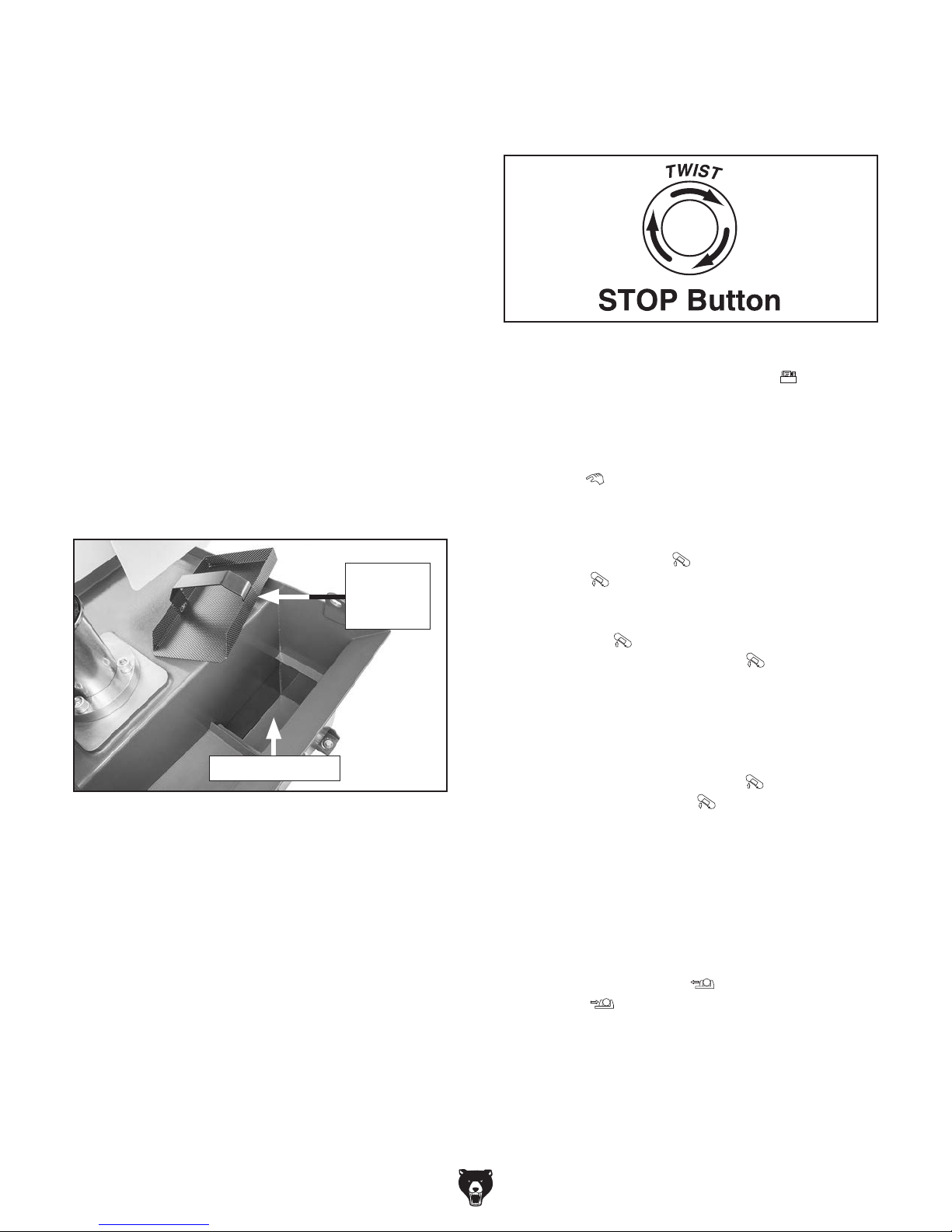
4. Remove chip collection tray and add 6.5
gallons of water to coolant reservoir (see
Figure 20). DO NOT run machine without
coolant in reservoir or coolant pump will be
damaged.
Note: For the Test Run, there is no need to
mix cutting fluid with the water.
Chip
Collection
Tray
Add Water Here
Figure 20. Coolant reservoir opening.
5. Push Emergency Stop button (C).
6. Connect machine to power source.
7. Turn master power switch ON. Power lamp
(B) on control panel should illuminate to indicate power is connected.
Note: Master power switch is located on
electrical panel access door, just below control panel (see Figure 2 on Page 4).
9. Push hydraulic pump button
(C). You
should hear hydraulic pump (located in
machine base) turn ON.
10. Turn operation mode switch (G) to manual
mode
.
11. Check function of headstock hydraulics and
3-phase power supply polarity by using raise
headstock button
button
(J) to raise and lower headstock.
(L) and lower headstock
— If headstock raises when raise headstock
button
lower headstock button
(L) is pushed and lowers when
(J) is pushed,
then phase polarity is correct. Remove
related shipping tag from control panel
and continue to Step 12.
— If headstock does not raise or lower when
raise headstock button
headstock button
(J) are pushed, then
(L) and lower
power phase polarity is not correct. Push
Emergency Stop button (C), disconnect
machine from power source, switch any
two of three power supply wires on plug
or hardwired connection, then restart Test
Run.
12. Check function of vise hydraulics by pressing
vise open button
button
(K).
(I) and vise close
-22-
Model G0886 (Mfd. Since 01/19)
Page 25

13. Check function of feed system by pressing
feed system button
roller switch (H) to FWD
(D), then turning feed
, REV , and OFF
.
Note: Vise must be in closed position for feed
system to function.
14. Push and hold raise headstock button
(L)
and raise headstock several inches.
15. Open coolant valves (see Figure 22).
Coolant should flow through blade guides
(see Figure 22) and onto blade when main
motor starts in Step 16.
18. WITHOUT resetting Emergency Stop button (C), push hydraulic pump button
vise close button
button
(E). The machine should not start.
(K), then blade start
(C),
— If machine does not start, Emergency Stop
button safety feature is working correctly.
Continue to Step 19.
— If machine does start (with Emergency
Stop button pushed in), immediately disconnect power. The Emergency Stop button safety feature is not working correctly.
This safety feature must work properly
before proceeding with regular operations.
Call Tech Support for help.
Left Blade Guide
Coolant Valve
Right Blade Guide
Coolant Valve
Left Blade
Guide
Right Blade
Guide
Figure 22. Location of coolant valves and blade
guides.
16. Start main motor and blade movement by
pushing blade start button
(E). Keep your
finger near Emergency Stop button (C). Verify
coolant flows through blade guides and onto
blade. The machine should run smoothly and
without problems or unusual noises.
Note: Vise must be in closed position for
main motor and blade movement to start.
19. Close coolant valves (see Figure 22).
20. Reset Emergency Stop button (C).
21. Turn operation mode switch (G) to auto
mode, and turn feed roller switch (H) to
forward
.
22. Push reset button (M) on the digital counter,
then use tabs (N) to set digital counter to 3.
23. Push hydraulic pump button
close button
(K), then blade start button
(C), vise
(E).
24. Trigger proximity sensor with a piece of metal
stock to start cutting cycle. (Metal stock must
1
be within
⁄4" of proximity sensor to trigger it.)
When headstock reaches bottom of travel,
blade should shut off and headstock should
move back to top of its travel.
— If blade does shut off and headstock does
move back to top of its travel, lower limit
stop is working correctly. Continue to
Step 25.
— If blade does not shut off or headstock
does not move back to top of its travel,
lower limit stop is not working correctly.
This safety feature must work properly
before proceeding with regular operations.
Refer to Page 54 to adjust lower limit stop
bolt.
17. Press Emergency Stop button (C) to completely to stop machine.
Model G0886 (Mfd. Since 01/19)
-23-
Page 26

25. Trigger proximity sensor with a piece of metal
stock to start cutting cycle again.
Disabling & Locking
26. Press Emergency Stop button (C) to com-
pletely to stop machine.
27. WITHOUT resetting Emergency Stop button (C), attempt to trigger proximity sensor
with a piece of metal stock to start cutting
cycle again.
— If cutting cycle does not start, Emergency
Stop button safety feature is working
correctly. Congratulations! Test Run is
complete.
— If cutting cycle does start (with Emergency
Stop button pushed in), immediately disconnect power. The Emergency Stop button safety feature is not working correctly.
This safety feature must work properly
before proceeding with regular operations.
Call Tech Support for help.
Switch
The master power switch can be disabled and
locked by inserting a padlock through it, as
shown. Locking the switch in this manner can
prevent unauthorized operation of the machine,
which is especially important if the machine is not
stored inside an access-restricted building.
IMPORTANT: Locking the switch with a padlock
only restricts its function. It is not a substitute
for disconnecting power from the machine when
adjusting or servicing.
1
Shaft
0
Recommended
Adjustments
The adjustments listed below have been performed at the factory. However, because of the
many variables involved with shipping, we recommend that you at least verify the following adjustments to ensure accurate cutting results.
Step-by-step instructions on verifying these adjustments can be found in SECTION 7: SERVICE.
Factory adjustments that should be verified:
1. Blade Tracking (Page 54).
2. Blade Guides (Page 56).
3. Squaring Blade to Table (Page 58).
Switch
Figure 23. Switch disabled by a padlock.
Children or untrained people can be
seriously injured by this machine. This
risk increases with unsupervised operation.
To help prevent unsupervised operation,
disable and lock the switch before leaving
machine unattended! Place key in a wellhidden or secure location.
Padlock
NOTICE
The padlock shaft diameter is important to
the disabling function of the switch. With
any padlock used to lock the switch, test
the switch after installation to ensure that it
is properly disabled.
-24-
0.20"
Figure 24. Maximum lock shaft requirements.
Model G0886 (Mfd. Since 01/19)
Page 27

SECTION 4: OPERATIONS
The purpose of this overview is to provide the novice machine operator with a basic understanding
of how the machine is used during operation, so
the
discussed later
in this manual
Due to the generic nature of this overview, it is
not intended to be an instructional guide. To learn
more about specific operations, read this entire
manual,
training from experienced
machine operators
outside of this manual by reading "how-to" books,
trade magazines, or websites.
To reduce your risk of
serious injury, read this
entire manual BEFORE
To reduce risk of eye injury from flying
Operation Overview
To complete a typical cutting operation, the
operator does the following:
1. Examines workpiece to make sure it is suit-
able for cutting.
machine controls/components
are easier to understand.
seek additional
, and do additional research
using machine.
2. Ensures machine has correct type and
amount of coolant for workpiece material
(refer to Coolant on Page 39 and Coolant
System on Page 48).
3. If needed, changes blade for workpiece mate-
rial (refer to Blade Selection on Page 26 and
Changing Blades on Page 28).
4. Sets proper blade speed for workpiece mate-
rial (refer to Blade Speed Chart on Page 33).
5. Verifies blade is properly tensioned (refer to
Tensioning Blade on Page 30).
6. Turns master power switch ON, then turns
hydraulic pump ON.
7. Securely clamps workpiece in vise using
manual and hydraulic controls (refer to Using
Vise on Page 35). Ensures workpiece is
stable and cutting area is free of obstructions.
chips or lung damage from breathing dust,
always wear safety glasses and a respirator
when operating this machine.
If you are not experienced with this type
of machine, WE STRONGLY RECOMMEND
that you seek additional training outside of
this manual. Read books/magazines or get
formal training before beginning any projects. Regardless of the content in this section, Grizzly Industrial will not be held liable
for accidents caused by lack of training.
Model G0886 (Mfd. Since 01/19)
8. Adjusts blade guide arm as close to
workpiece as possible (refer to Blade Guides
on Page 35).
9. Raises headstock to required height for
workpiece (refer to Setting Headstock
Height on Page 36).
10. Sets proper blade feed rate for workpiece
material (refer to Setting Blade Feed Rate
on Page 36)
11. Sets up proximity sensor as needed for cutting operations (refer to Proximity Sensor on
Page 37).
12. Selects manual or auto operation mode,
depending on number of cuts needed (refer
to Feed System on Page 37).
-25-
Page 28

13. Puts on safety glasses and respirator.
14. Opens coolant valves (refer to Using Coolant
System on Page 39).
15. Starts blade movement, and allows machine
to complete cut(s).
16. Inspects chips and adjusts blade feed rate as
needed (refer to Chip Inspection Chart on
Page 34).
17. When finished, turns machine OFF.
Blade Selection
Blade Selection
Selecting the right blade for the cut requires a
knowledge of various blade characteristics.
F. Gullet Depth: The distance from the tooth tip
to the bottom of the curved area (gullet).
G. Tooth Pitch: The distance between tooth
tips.
H. Blade Back: The distance between the bot-
tom of the gullet and the back edge of the
blade.
I. Blade Pitch or TPI: The number of teeth per
inch measured from gullet to gullet.
Blade Length
Measured by the blade circumference, blade
lengths are usually unique to the brand of bandsaw
and the distance between the wheels.
Model Blade Length Range
G0886 ............................................ 155
1
⁄4"–1553⁄4"
Blade Terminology
A
B
C
E
D
Figure 25. Bandsaw blade terminology.
A. Kerf: The amount of material removed by the
blade during cutting.
B. Tooth Set: The amount each tooth is bent
left or right from the blade.
F
G
H
I
Blade Width
Measured from the back of the blade to the tip of
the blade tooth (the widest point).
Model Blade Width
G0886 ............................................................1
3
⁄8"
Tooth Type
The most common tooth types are described as
follows, and illustrated in Figure 26.
Standard (or Raker)
Variable Pitch (VP)
C. Gauge: The thickness of the blade.
D. Blade Width: The widest point of the blade
measured from the tip of the tooth to the back
edge of the blade.
E. Tooth Rake: The angle of the tooth face from
a line perpendicular to the length of the blade.
-26-
Figure 26. Bandsaw blade tooth types.
Standard or Raker: Equally spaced teeth set at
a "0" rake angle. Recommended for all purpose
use.
Variable Pitch (VP): Varying gullet depth and
tooth spacing, a "0" rake angle, excellent chip
removing capacity, and smooth cutting.
Model G0886 (Mfd. Since 01/19)
Page 29

Blade Pitch (TPI)
The chart below is a basic starting point for
choosing teeth per inch (TPI) for variable pitch
blades and standard raker set bi-metal blades/
HSS blades. However, for exact specifications of
bandsaw blades that are correct for your operation, contact the blade manufacturer.
3. Refer to "Material Shapes" row and find
shape of material to be cut.
4. In applicable row, read across to right and
find box where row and column intersect.
Listed in the box is minimum TPI recommended for variable tooth pitch blades.
To select correct blade pitch:
1. Measure material thickness. This measure-
ment is distance from where each tooth
enters workpiece to where it exits workpiece.
2. Refer to "Material Width/Diameter" row of
blade selection chart in Figure 27, and read
across to find workpiece thickness you need
to cut.
Material Width/Diameter
Teeth Per Inch (TPI) for Bandsaw Blades
Material Shapes
TOOTH SELECTION
mm
50
inch
2 3 4 5 6 7 8 9 10 11 12 13 14 15 16 17 18 192½ 3½
75 100 150 200 250 300 350 400
3/4
4/6
2/3
2/3 1.4/2.5
5/8
4/6
3/4
The TPI range is represented by a "/" between
numbers. For example, 3/4 TPI is the same
as 3–4 TPI.
The "Cutting Speed Rate Recommendation"
chart, which is located on the machine just
below the Blade Pitch Chart, offers guidelines
for various metals, given in feet per minute
(FPM). Refer to Blade Speed Chart section
on Page 33 for further details.
450
3/4
1.4/2.5
2/3
1.5/.8
1.5/.8
Figure 27. General guidelines for blade selection and speed chart.
Model G0886 (Mfd. Since 01/19)
-27-
Page 30

Changing Blades
Changing Blades
7. Remove both blade guards and blade brush
(see Figure 31).
All saw blades are dangerous and may cause personal injury. To reduce
the risk of being injured,
wear leather gloves when
handling and uncoiling saw
blades.
Item(s) Needed Qty
Assistant ............................................................ 1
Leather Gloves (per person) .............................. 1
Hex Wrenches 4, 5mm ................................ 1 ea.
Blades should be changed when they become
dull, damaged, or when cutting materials that
require a blade of a certain type or tooth count.
To change blade on bandsaw:
1. Push hydraulic pump button
hydraulic pump ON.
to turn
Left Blade
Guard
Figure 28. Location of blade guards and blade
brush.
8. Loosen adjustable handle on left blade guide
arm and move arm until it contacts stop pin
on scale, as shown in Figure 29.
Right Blade
Guard
Blade Brush
Stop
Pin
2. Push raise headstock button
headstock approximately 6 inches.
3. DISCONNECT MACHINE FROM POWER!
4. Remove cutoff chute and move proximity
sensor out of the way.
5. Open both wheel covers.
6. Clean out all chips and shavings with a brush
and shop vacuum.
and raise
Adjustable
Left Blade
Guide Arm
Figure 29. Left blade guide arm positioned.
Handle
-28-
Model G0886 (Mfd. Since 01/19)
Page 31

9. Loosen blade tension handwheel (see
Figure 30), and remove blade from wheels.
Blade
Tension
Handwheel
Figure 30. Location of blade tension handwheel.
10. With help of an assistant, insert new blade
through both blade guides and bearings (see
Figure 31, then position it around wheels.
Note: It is sometimes possible to flip the
blade inside out, in which case the blade
will be installed in the wrong direction. After
installing, check to make sure the blade
teeth face the same direction as blade travel
(see Figure 32). Some blades will have a
directional arrow as a guide.
Blade Travel
Figure 32. Example of blade cutting direction.
Idler Wheel
Bearings
Blade
Blade
Bearings
Guides
Figure 31. Installing new blade.
11. Apply a light amount of tension to hold blade
in place. Work your way around blade to
adjust position so back of blade is against
shoulder of wheels, as shown in Figure 33.
Wheel
Shoulder
Blade
Figure 33. Blade installed on wheels.
12. Perform Tensioning Blade procedure that
follows this section.
Model G0886 (Mfd. Since 01/19)
13. Re-install blade brush and blade guards, then
close wheel covers. Ensure guards do not
touch blade.
-29-
Page 32

Tensioning Blade
3. Remove left blade guard extension, as shown
in Figure 34.
Tensioning Blade
Proper blade tension is essential to avoid blade
vibration, twist, or slippage on the wheels. A correctly tensioned blade provides long blade life,
straight cuts, and efficient cutting times.
The three major signs of incorrect blade tension
are: 1) The blade stalls in the cut and slips on the
wheels, 2) the blade frequently breaks, and 3) the
bandsaw does not make straight cuts.
Loosen blade tension at the end of each day
to prolong blade life.
To tension bandsaw blade:
1. DISCONNECT MACHINE FROM POWER!
2. Perform a quick blade tracking check by slid-
ing a fingernail between end of blade and
wheel shoulder.
— If there is just enough space to fit a fin-
gernail, then blade tracking is properly
adjusted. Continue to Step 3.
4. Loosen adjustable handle on left blade guide
arm and move arm as far left as it will go,
as shown in Figure 34. Tighten adjustable
handle to secure arm position.
Left Blade
Guide Arm
Left Blade
Guard Extension
Removed
Figure 34. Left blade guide arm positioned for
blade tensioning.
5. Turn blade tension handwheel (see
Figure 35) clockwise to tighten blade or
counterclockwise to loosen blade.
6. Adjust blade tension handwheel until indicator on blade tension gauge moves into green
section, as shown in Figure 35.
Adjustable
Handle
— If there is too little or too much space to fit
a fingernail, then blade tracking must be
properly adjusted before tensioning blade.
(Refer to Adjusting Blade Tracking on
Page 54.)
Green
Section
Indicator
Figure 35. Blade tension properly set.
Blade
Tension
Gauge
Blade
Tension
Handwheel
-30-
Model G0886 (Mfd. Since 01/19)
Page 33

Blade Breakage
Many conditions may cause a bandsaw blade to
break. Some of these conditions are unavoidable
and are the natural result of the stresses placed
on the bandsaw; other causes of blade breakage
are avoidable.
The most common causes of avoidable blade
breakage are:
• Faulty alignment or adjustment of the blade
guides.
• Feeding blade through the workpiece too
fast.
Blade Care &
Break-In
Blade Care
To prolong blade life, always use a blade with the
proper width, set, type, and pitch for each application. Maintain the appropriate feed rate, feed
pressure, and blade speed, and pay attention to
the chip characteristics (Refer to Blade Speed
Chart on Page 33 and Chip Inspection Chart
on Page 34). Keep your blades clean, since dirty
or gummed up blades pass through the cutting
material with much more resistance than clean
blades, causing unnecessary heat.
Blade Care
• Dull or damaged teeth.
• Improperly-tensioned blade.
• Left blade guide assembly set too high above
the workpiece. Adjust left blade guide assembly as close to workpiece as possible.
• Using a blade with a lumpy or improperly fin-
ished braze or weld.
• Leaving the blade tensioned when not in use.
• Using the wrong blade pitch (TPI) for the
workpiece thickness. The general rule of
thumb is to have no fewer than three teeth
in contact with the workpiece when starting a
cut and at all times during cutting.
Blade Break-In
The tips and edges of a new blade are extremely
sharp. Cutting at too fast of a feed rate or too
slow of a blade speed can fracture these tips and
edges, quickly dulling the blade. Properly breaking in a blade allows these sharp edges to wear
without fracturing, thus keeping the blade sharp
longer. Below is a typical break in procedure. For
aftermarket blades, refer to the manufacturer's
break-in procedure to keep from voiding the
warranty.
Use the Chip Inspection Chart on Page 34 as
a guide to evaluate the chips and ensure that the
optimal blade speed and feed rate are being used.
To properly break in new blade:
1. Choose correct speed for blade and material
type.
2. Reduce feed pressure by half for first 50–100
2
of material cut.
in
Blade Break-In
Model G0886 (Mfd. Since 01/19)
3. To avoid twisting blade when cutting, adjust
feed pressure when total width of blade is in
cut.
-31-
Page 34

Changing Blade
Speed
Changing Blade Speed
2. Remove (4) knob bolts (see Figure 37) that
secure pulley cover to frame. Support pulley
cover as you remove knob bolts.
Entanglement Hazard!
You MUST install the pulley cover before operating or severe injury may
occur.
Blade Speed
The Model G0886 has four speed settings—92,
161, 236, and 338 feet per minute (FPM). These
different speed settings are changed by moving
belt position on pulleys (see Figure 36). Refer to
the chart on Page 33 for cutting speed recommendations by material type.
92
161
236
338
Figure 36. V-belt positions in FPM.
MotorDrive Wheel
Upper Knob
Bolts
Lower Knob
Bolts
Figure 37. Location of pulley cover knob bolts.
3. Loosen upper motor mount hex bolts (see
Figure 38), allowing motor to pivot and V-belt
to slacken.
During operation, pay attention to the chips being
produced from the cut and compare them to the
Chip Inspection Chart on Page 34 to properly
set the blade speed.
Item(s) Needed Qty
Open-End or Socket Wrench 19mm ................. 1
Scrap 2x4 12" .................................................... 1
To change blade speeds:
1. DISCONNECT MACHINE FROM POWER!
Hex
Bolt
Motor
Motor Mount
Figure 38. Location of motor mount hex bolts.
4. Move V-belt to required pulley combination
(see Figure 36).
5. Use 2x4 to leverage motor and tension V-belt,
then tighten hex bolts loosened in Step 3.
6. Close and secure pulley cover with knob
bolts removed in Step 2.
Hex
Bolt
-32-
Model G0886 (Mfd. Since 01/19)
Page 35

Blade Speed Chart
Blade Speed Chart
The chart in Figure 39 offers blade speed guidelines for various metals, given in feet per minute (FPM)
and meters per minute (M/Min). Choose the closest available speed on the machine, then adjust the feed
rate as necessary, using the appearance of the chips produced as a guide. Refer to the Chip Inspection
Chart that follows for recommendations on adjusting feed rate or blade speed based on the appearance of
the chips produced.
Material
Carbon
Steel
Angle
Steel
Thin Tube
Aluminum
Alloy
Copper
Alloy
Speed FPM
(M/Min)
196~354
(60) (108)
180~220
(54) (67)
180~220
(54) (67)
220~534
(67) (163)
229~482
(70) (147)
Material
Tool Steel
High-
Speed
Tool Steel
Cold-Work
Tool Steel
Hot-Work
Tool Steel
OilHardened
Tool Steel
Speed FPM
(M/Min)
203
(62)
75 ~118
(25) (36)
95~213
(29) (65)
203
(62)
203 ~213
(62) (65)
Figure 39. Blade speed chart.
Material
Alloy Steel
Mold Steel
WaterHardened
Tool Steel
Stainless
Steel
CR
Stainless
Steel
Speed FPM
(M/Min)
111~ 32 1
(34) (98)
246
(75)
242
(74)
85
(26)
85~203
(26) (62)
Material
Free
Machining
Stainless
Steel
Gray Cast
Iron
Ductile
Austenitic
Cast Iron
Malleable
Cast Iron
Plastics &
Lumber
Speed FPM
(M/Min)
150 ~203
(46) (62)
108~225
(33) (75)
65~85
(20) (26)
321
(98)
220
(67)
Model G0886 (Mfd. Since 01/19)
-33-
Page 36

Chip Inspection Chart
thin & curled
thin & curled
short, hard & thick
thin & curled
short, hard & thick
thick, hard & strong
thin & curled
short, hard & thick
thick, hard & strong
thick, hard & strong
thin & curled
short, hard & thick
thick, hard & strong
thick, hard & strong
hard & thin
thin & curled
short, hard & thick
thick, hard & strong
thick, hard & strong
thin & straight
hard & thin
thin & curled
short, hard & thick
thick, hard & strong
thick, hard & strong
thin & straight
powdery
hard & thin
thin & curled
short, hard & thick
thick, hard & strong
thick, hard & strong
thin & straight
powdery
thin & curled tightly
hard & thin
Chip Inspection Chart
The best method for choosing the cutting speed and feed rate for a cutting operation is to inspect the chips
created by the cut. These chips are indicators of what is commonly referred to as the "chip load." Refer to
the chip inspection chart below to evaluate chip characteristics and determine whether to adjust feed rate/
pressure, blade speed, or both.
Chip
Appearance
Chip
Description
Chip
Color
Blade
Speed
Feed Rate/
Pressure
Thin & Curled Silver Good Good
Hard, Thick &
Short
Hard, Strong &
Thick
Hard, Strong,
Curled & Thick
Hard, Coiled &
Thin
Brown or Blue Increase Decrease
Brown or Blue Increase Decrease
Silver or Light
Brown
Good
Decrease
Slightly
Silver Increase Decrease
Straight & Thin Silver Good Increase
Powdery Silver Decrease Increase
Coiled, Tight &
Thin
Silver Good Decrease
Figure 40. Chip inspection chart.
Other
Actions
Check Blade
Pitch
Check Blade
Pitch
Check Blade
Pitch
-34-
Model G0886 (Mfd. Since 01/19)
Page 37

Using Vise
Note: Figure 42 shows correct methods of
holding different workpiece shapes.
Using Vise
To avoid serious injury, always turn saw
OFF and allow blade to come to complete
stop before adjusting vise!
The movable vise jaw (see Figure 41) is adjusted
manually with the vise handwheel and is locked
in position hydraulically. Motorized rollers on the
clamping surface of the vise jaw move workpieces
into and out of cutting position. The fixed vise jaw
is a stationary clamping surface that has nonmotorized rollers.
Fixed
Vise
Vise
Handwheel
NOT
RECOMMENDED
Figure 42. Example of workpiece holding options
by material shape.
RECOMMENDED
Movable
Vise
Figure 41. Location of vise components.
To use vise:
1. Push hydraulic pump button
hydraulic pump ON.
2. Push vise open button
pressure on movable vise jaw.
3. Insert workpiece between jaws. Use vise
handwheel to move vise jaw until it just contacts workpiece.
IMPORTANT: Use roller stands or tables to
support long workpieces.
4. Push vise close button
workpiece. Between cuts, use vise open
button
new workpiece.
to release and reposition/reload a
to release any
to turn
to clamp
Blade Guides
Blade Guides
The left blade guide should be as close to the
workpiece as possible during cutting operations.
This will help ensure straight cuts by keeping the
blade from twisting and drifting off the cut line.
To adjust the left bl ad e g u id e, loosen the adjustable
handle on left blade guide arm (see Figure 43)
and slide the arm/guide as close to the workpiece
as possible, then tighten the adjustable handle.
Left Blade
Guide Arm
Adjustable Handle
Left Blade Guide
Right Blade Guide
Model G0886 (Mfd. Since 01/19)
Figure 43. Blade guides.
-35-
Page 38

Setting Headstock
Setting Blade Feed
Height
Setting Headstock Height Setting Blade Feed Rate
The height that the headstock will travel is controlled by the upper limit switch and the height
adjustment rod and bracket (see Figure 44).
Headstock height should be set to match the
height of the workpiece. This speeds up repetitive
cuts by eliminating unnecessary headstock travel.
Adjustment
Rod
Adjustment
Bracket
Knob Bolt
Upper Limit
Switch
Rate
The speed at which the saw blade will cut through
a workpiece is determined by blade type, feed
rate, and feed pressure. The feed rate is controlled by the blade feed-rate dial on the control
panel.
Note: If a lubricant is used on the cut, the feed
rate can be increased by approximately 15%.
To set blade feed rate:
1. Push hydraulic pump button
hydraulic pump ON.
2. Push raise headstock button
headstock to required height for workpiece.
3. Adjust blade feed-rate dial shown in Figure 45
to desired feed rate from 0 (slowest) to
10 (fastest).
to turn
and raise
Figure 44. Headstock height controls.
To set headstock height:
1. Push hydraulic pump button
hydraulic pump ON.
2. Insert workpiece between jaws (refer to
Using Vise on Page 35). Use roller stands
or tables to support long pieces.
3. Push raise headstock button
headstock so bottom of blade is approximately
4. DISCONNECT MACHINE FROM POWER!
5. Loosen knob bolt on height adjustment
bracket, and position adjustment rod so it
just touches upper limit switch trigger.
6. Tighten knob bolt.
1
⁄2" above top of workpiece.
to turn
and raise
Blade Feed-Rate Dial
Figure 45. Feed rate dial.
4. Proceed with cutting operations.
5. Examine metal chips created from cutting
operation, and adjust feed rate as necessary
for optimum cutting performance (refer to
Chip Inspection Chart on Page 34 for more
details).
-36-
Model G0886 (Mfd. Since 01/19)
Page 39

Feed System
Proximity Sensor
Feed System
The feed system allows you to make repetitive
cuts without adjusting the vise and moving the
workpiece after every cut. The movable vise jaw
(see Figure 46) is equipped with motorized rollers
that move the workpiece into cutting position. The
fixed vise jaw has non-motorized rollers. The rollers are precisely aligned at the factory and do not
require adjustment.
Motorized
Rollers
Non-Motorized
Rollers
Figure 46. Vise jaw rollers.
The feed system works in manual and auto
operation mode. In both operation modes, the feed
system is stopped when the workpiece reaches
the proximity sensor head (refer to Proximity
Sensor section).
Proximity Sensor
The proximity sensor (see Figure 48) on the
Model G0886 functions as a work stop in manual
operation mode and as a work stop and trigger for
the feed system in auto operation mode. It can be
set for repetitive cutting operations up to 16" long.
There are three components to the proximity
sensor. The head (see Figure 48) detects the
presence of metal materials within a
The bracket and bar allow the sensor head to be
positioned to accommodate a variety of workpiece
shapes and sizes. The adjustment knob moves
the sensor bracket and head in fine increments to
ensure exact cut lengths.
The cutoff chute (see Figure 48) must be installed
when using the proximity sensor. Processed
material needs to be quickly removed from the
area for the proximity sensor to function correctly.
Blade
Head
1
⁄4" range.
Adjustment
Knob
In manual operation mode, the feed system
button
engage the feed system, and then the feed roller
switch is used to control the feed rollers. The feed
roller switch has three settings: OFF
and REV
engaged in auto operation mode; however, the
feed roller switch must be set to FWD
ting operations.
Model G0886 (Mfd. Since 01/19)
(see Figure 47) must be pushed to
, FWD ,
. The feed system is automatically
for cut-
Feed System Button
Feed Roller Switch
Figure 47. Feed system controls.
Chute
Workpiece
Bar
Figure 48. Proximity sensor set to cut 13"
lengths of pipe.
Using Proximity Sensor in Manual
Operation Mode
1. Make sure master power switch is turned
OFF.
2. Place workpiece between jaws. Use roller
stands or tables to support long pieces.
3. Turn master power switch ON.
-37-
Page 40

4. Push hydraulic pump button to turn
hydraulic pump ON.
5. Set headstock to required height for workpiece
(refer to Setting Headstock Height on
Page 36).
6. Make sure operation mode switch is set to
manual
to OFF
mode and feed roller switch is set
.
6. Make sure operation mode switch is set to
auto
FWD
mode and feed roller switch is set to
.
7. Extend workpiece past blade the same length
of pieces needed. Measure from outside
of blade to end of workpiece, as shown in
Figure 48.
8. Push vise close button
to clamp workpiece.
7. Extend workpiece past blade the same length
of pieces needed. Measure from outside
of blade to end of workpiece, as shown in
Figure 48.
8. Push vise close button
to clamp workpiece.
9. Position proximity sensor so arrow on sensor
head points directly at end of workpiece, as
shown in Figure 48. Sensor head needs to
1
be within
⁄4" of material for detection.
10. If needed, open coolant valves.
11. Push blade start button
to start cutting
operation. Processed material will slide down
chute after cut is made.
12. Set feed roller switch to FWD
feed system button
. Feed rollers will
, and push
advance workpiece until it reaches proximity
sensor.
13. Repeat Steps 11–12 as needed to complete
cutting operations
Using Proximity Sensor in Auto
Operation Mode
1. Make sure master power switch is turned
OFF.
2. Place workpiece between jaws. Use roller
stands or tables to support long pieces.
3. Turn master power switch ON.
9. Position proximity sensor so arrow on sensor
head points directly at end of workpiece, as
shown in Figure 48. Sensor head needs to
1
be within
⁄4" of material for detection.
10. If needed, open coolant valves.
11. Use tabs on digital counter (see Figure 49) to
set the number of cuts to be made.
Digital
Counter
Display
Reset Button
Tabs
Figure 49. Digital counter set to 7 with 2 cuts
completed.
12. Push blade start button
to start cutting operation. During cutting operation, feed
roller will automatically advance workpiece
until it reaches proximity sensor, and digital
counter will display number of cuts completed
(see Figure 49). Cutoff pieces will slide down
chute after each cut is made.
13. When cutting operation is complete, press
RESET button on digital counter to clear
display.
4. Push hydraulic pump button
hydraulic pump ON.
5. Set headstock to required height for workpiece
(refer to Setting Headstock Height on
Page 36).
-38-
to turn
Model G0886 (Mfd. Since 01/19)
Page 41

Coolant
Using Coolant
Coolant
Coolant is a mixture of cutting fluid and water.
While simple in concept and function, many
issues must be taken into account to mix and
use the correct coolant. Always follow all product
warnings, specifications, and contact the cutting
fluid manufacturer for unanswered questions.
Use the information below as a guideline to
choose the appropriate coolant. Always refer to
the cutting fluid manufacturer for specific application and safety information:
• For cutting low alloy, low carbon, and general-purpose category metals with a bi-metal
blade —use a water soluble cutting fluid.
• For cutting stainless steels, high carbon, and
high alloy metals, brass, copper, and mild
steels—use "Neat Cutting Oil" (commonly
undiluted mineral oils) that have extreme
pressure additives (EP additives).
• For cutting cast iron, coolant is not
recommended.
Tip: Using a refractometer or hydrometer to
replenish water in water-based coolant can extend
the life of blades and coolant, and ensure consistent cutting results.
System
Using Coolant System
FIRE HAZARD! DO NOT cut
magnesium when using oilwater solutions as coolant!
Always use coolant intended for magnesium. Water in
the solution could cause a
magnesium-chip fire.
This bandsaw has a built-in coolant system
that can extend the life of your bandsaw blades
by lowering the temperature of the blade and
workpiece if used properly when cutting.
NEVER run machine without coolant in the
reservoir or when coolant is below low mark
or you will overheat pump and void warranty! See Adding Coolant on Page 48 for
instructions.
The coolant pump runs automatically when the
main motor is ON (i.e. the blade is running). Two
coolant valves (see Figure 50) control the flow of
coolant onto the blade through the blade guides.
BIOLOGICAL AND POISON
HAZARD! Use proper personal protection equipment
when handling coolant and
follow federal, state, and
fluid manufacturer requirements to properly dispose
of coolant.
Model G0886 (Mfd. Since 01/19)
IMPORTANT: Too much flow at the blade guides
will make a mess and can make work area unsafe;
and not enough flow at the cut will overheat blade,
causing blade teeth to load up and break.
Left Blade-Guide
Coolant Valve
Right Blade-Guide
Coolant Valve
Figure 50. Coolant valves open.
-39-
Page 42

Operation Tips
The following tips will help you safely and effectively operate your bandsaw, and help you get the
maximum life out of your saw blades.
Tips for cutting:
Workpiece
Inspection
Some metal workpieces are not safe to cut with a
metal cutting bandsaw; instead, a different tool or
machine should be used.
• Use the proximity sensor to quickly and accurately cut multiple pieces of stock to the same
length.
• Clamp workpiece firmly in the vise jaws to
ensure a straight.
• Use auto operation mode to speed
production.
• Allow blade to reach full speed before cutting
workpiece. Never start a cut with the blade in
contact with the workpiece, and do not start a
cut on a sharp edge.
• Chips should be curled and silvery. If the
chips are thin and powder-like, increase your
feed rate.
• Burned chips indicate a need to reduce your
blade speed.
• Wait until blade has completely stopped
before removing workpiece from vise. Avoid
touching the cut end—it could be very hot!
• Support long pieces so they will not fall when
cut. Flag long ends to alert passers-by of
potential danger.
• Adjust left blade guide as close as possible to
the workpiece to minimize side-to-side blade
movement.
• Use coolant when possible to increase blade
life, and keep the chip collection tray clear so
coolant can recycle to reservoir and pump.
Loosen blade tension at the end of each day
to prolong blade life.
Before cutting, inspect the material for any of
the following conditions and take the necessary precautions:
• Small or Thin Workpieces: Small or thin
workpieces may be damaged during cutting—avoid cutting these workpieces if possible. If you must cut a small or thin workpiece,
attach it to or clamp it between larger scrap
pieces that will both support the workpiece
through the cut. Some thin sheet metals will
not withstand the forces from this bandsaw
during cutting; instead, use a shear, nibblers,
or sheet metal nippers to cut these pieces.
• Unstable Workpieces: Workpieces that cannot be properly supported or stabilized with
the vise should not be cut on this bandsaw.
Examples are chains, cables, workpieces
with internal or built-in moving or rotating
parts, etc.
• Material Hardness: Always factor in the hardness of the metal before cutting it. Hardened
metals will take longer to cut, may require
lubrication, and may require a different type
of blade in order to efficiently cut them.
• Tanks, Cylinders, Containers, Valves, Etc:
Cutting into containers that are pressurized or contain gasses or liquids can cause
explosions, fires, caustic burns, or machine
damage. Avoid cutting any of these types of
containers unless you have verified that the
container is empty and it can be properly supported during a cut.
• Magnesium: Pure magnesium burns easily. Cutting magnesium with a dull blade can
create enough friction to ignite the small
magnesium chips. Avoid cutting magnesium
if possible.
-40-
Model G0886 (Mfd. Since 01/19)
Page 43

Installing unapproved accessories may
order online at www.grizzly.com or call 1-800-523-4777
Accessories
cause machine to malfunction, resulting in
serious personal injury or machine damage.
To reduce this risk, only install accessories
recommended for this machine by Grizzly.
SECTION 5: ACCESSORIES
NOTICE
Refer to our website or latest catalog for
additional recommended accessories.
Replacement Bi-Metal Bandsaw Blades
T30686—155" x 1-1/4" x 0.043 3–4 TPI
T30687—155" x 1-1/4" x 0.043 4–6 TPI
T30688—155" x 1-1/4" x 0.043 5–8 TPI
T30689—155" x 1-1/4" x 0.043 6 –10 TPI
H9240—Water Soluble Machining Oil
Rustlick water soluble machining oil contains
effective chlorinated E.P. additive to provide excellent tool life. Guaranteed to protect neoprene
seals. Great for general purpose or heavy duty
applications. Can be used on all metals except
titanium.
Figure 53. H9240 Rustlick Machining Oil.
Figure 51. Typical variable pitch bi-metal cutting
blade.
T28172—14" x 39" Heavy-Duty Roller Table
Use this versatile roller table wherever you need
extra workpiece support.
Basic Eye Protection
T20501—Face Shield Crown Protector 4"
T20502—Face Shield Crown Protector 7"
T20503—Face Shield Window
T20451—“Kirova” Clear Safety Glasses
T20452—“Kirova” Anti-Reflective S. Glasses
T20456—DAKURA Safety Glasses
T20502
T20503
T20456
Figure 54. Assortment of basic eye protection.
T20452
T20451
Figure 52. T28172 Heavy-Duty Roller Table.
Model G0886 (Mfd. Since 01/19)
-41-
Page 44

SECTION 6: MAINTENANCE
To reduce risk of shock or
accidental startup, always
disconnect machine from
Cleaning &
Protecting
power before adjustments,
maintenance, or service.
Schedule
For optimum performance from this machine, this
maintenance schedule must be strictly followed.
Ongoing
To maintain a low risk of injury and proper
machine operation, if you ever observe any of the
items below, shut down the machine immediately
and fix the problem before continuing operations:
• Loose mounting bolts.
• Damaged or dull saw blade.
• Worn or damaged wires.
• Any other unsafe condition.
Daily:
• Protect headstock pillar and ram strut (see
Figure 55).
• Lubricate blade and blade guides (Page 43).
• Clean/lubricate vise table (Page 44).
• Clean metal chips from upper and lower
wheel areas.
Monthly:
• Lubricate blade tension leadscrew (Page 43).
• Clean/lubricate vise leadscrew (Page 44).
• Lubricate headstock column (Page 44).
• Lubricate blade guide arm gib (Page 44).
• Remove blade and clean wheels.
• Check gearbox oil level (Page 45).
Use a brush and shop vacuum to remove chips
and other debris from the working surfaces.
Remove any rust build-up from unpainted cast
iron surfaces of your machine and treat with a
non-staining lubricant after cleaning.
Use a shop rag to apply a thin coat of quality
metal protectant to the headstock pillar and ram
strut (see Figure 55) to prevent corrosion.
Headstock Pillar & Ram Strut
Pillar
Ram
Strut
Figure 55. Location of headstock pillar and ram
strut.
G2870—T-9 Boeshield, 4 Oz.
G2871—T-9 Boeshield, 12 Oz.
This protective spray penetrates deep and holds
up the longest against corrosive environments.
Boeshield
Bi-annually:
• Change gearbox oil (Page 45).
-42-
Figure 56. T-9 Boeshield.
Model G0886 (Mfd. Since 01/19)
Page 45

Lubrication
Lubrication
The bearings on your bandsaw are factory lubricated and sealed. Leave them alone unless they
need to be replaced.
Use the schedule below and the following instructions to properly lubricate the other components
that require lubrication.
Blade & Blade Guides
Lube Type . . Model SB1365 or ISO 68 Equivalent
Oil Amount ...........................................1–2 Drops
Lubrication Frequency ................................. Daily
Blade & Blade Guides
Place one or two drops of light machine oil on
blade and blade guides (see Figure 59) daily,
especially when cutting cast iron, as no coolant is
required when cutting cast iron.
Frequency
Lubrication Task
Blade & Blade Guides 8 Hrs.
Blade Tension Leadscrew 40 Hrs.
Vise Table 8 Hrs.
Vise Leadscrew 40 Hrs.
Headstock Column 40 Hrs.
Blade Guide Arm Gib 40 Hrs.
Drive Shaft, Headstock Pillar 160 Hrs.
Gearbox Special
Figure 57. Recommended lubrication tasks.
Item(s) Needed Qty
NLGI#2 Grease (T26419 or Equivalent) . As Needed
ISO 68 Oil (SB1365 or Equivalent) .........As Needed
ISO 320 Oil (T28042 or Equivalent) .......As Needed
Clean Shop Rags .................................... As Needed
Stiff Brush .................................................................1
Clean Brush ..............................................................1
Grease Gun ..............................................................1
1-Gallon Drain Pan ...................................................1
Funnel .......................................................................1
Teflon Thread Tape ................................. As Needed
Open-End Wrenches 19, 21mm ....................... 1 Ea.
(Hours of
Operation)
Page
Ref.
42
42
44
44
44
44
44
45
Blade
Left Blade
Guide
Figure 59. Blade and blade guides.
Right Blade
Guide
Blade Tension Leadscrew
Lube Type . . Model SB1365 or ISO 68 Equivalent
Oil Amount ...........................................1–2 Drops
Lubrication Frequency ..............................Weekly
Blade Tension Leadscrew
Lubricate the blade tension leadscrew with 1–2
drops of light machine oil weekly (see Figure 60).
Wipe off excess oil with a clean rag.
SB1365—South Bend Way Oil-ISO 68
T26419 —Syn–O–Gen Synthetic Grease
Figure 58. Recommended products for machine
lubrication.
Model G0886 (Mfd. Since 01/19)
Blade Tension
Leadscrew
Figure 60. Blade tension leadscrew.
-43-
Page 46

Vise Table
Lube Type . . Model SB1365 or ISO 68 Equivalent
Oil Amount ............................................Thin Coat
Lubrication Frequency ................................. Daily
Vise Table
Keep the vise table (see Figure 61) surface rustfree with regular applications of a quality way oil.
Vise Leadscrew
Lube Type ............. SB1365 or ISO 68 Equivalent
Oil Amount ............................................Thin Coat
Lubrication Frequency ..............................Weekly
Use mineral spirits, shop rags, and a stiff brush to
clean the vise leadscrew. When dry, use a clean
brush to apply a thin coat of oil to the leadscrew
threads (see Figure 61).
Vise Leadscrew
Vise Leadscrew
Blade Guide Arm Gib
Blade Guide Arm Gib
Lube Type . . Model SB1365 or ISO 68 Equivalent
Oil Amount ............................................Thin Coat
Lubrication Frequency ..............................Weekly
Keep the unpainted surfaces of the blade guide
arm gib (see Figure 63) rust-free with regular
applications of a quality way oil.
Blade Guide
Arm Gib
Figure 63. Blade guide arm gib.
Vise Table
Figure 61. Vise table and vise leadscrew.
Headstock Column
Lube Type . . Model SB1365 or ISO 68 Equivalent
Oil Amount ............................................Thin Coat
Lubrication Frequency ..............................Weekly
Headstock Column
Keep the unpainted surfaces of the headstock
column (see Figure 62) rust-free with regular
applications of a quality way oil.
Headstock
Column
Drive Shaft & Headstock Pillar
Lube Type ............. T26419 or NLGI#2 Equivalent
Amount .............................................. 1–2 Pumps
Lubrication Frequency .............................Monthly
Apply grease to drive shaft and headstock pillar
using grease fittings shown in Figure 64.
Drive Shaft & Headstock Pillar
Drive Shaft
Grease Fitting
Figure 62. Headstock column.
-44-
Headstock Pillar
Grease Fitting
Figure 64. Grease fitting locations.
Model G0886 (Mfd. Since 01/19)
Page 47

Gearbox
Gearbox
Lube Type ............T28042 or ISO 320 Equivalent
Amount ................................................... 0.84 Qt.
Check Frequency .....................................Weekly
Lubrication Frequency . . After 50 Hrs, Bi-annually
IMPORTANT: To maximize gearbox life, drain
and refill it after the first 50 hours of use.
As routine maintenance, the gearbox should be
completely drained and refilled every 6 months.
To drain and refill gearbox:
1. Run blade continuously for approximately 10
minutes to warm up gear oil.
2. Raise headstock to highest position.
After the first 50 hours of use, the fluid level of the
gearbox should be checked weekly. The gearbox
has a sight tube (see Figure 65) to check fluid
level. The sight tube should be filled with gear oil.
If it's not, remove fill plug with breather tube (see
Figure 66), and slowly add just enough gear oil to
fill sight tube. When replacing fill plug, be sure to
re-wrap threads with Teflon tape to prevent leaks.
Sight
Tube
Figure 65. Gearbox sight tube location.
3. DISCONNECT MACHINE FROM POWER!
4. Remove gearbox fill plug (see Figure 66).
5. Place drain pan under drain plug (see
Figure 67), remove drain plug, and then
drain gear oil.
Drain
Plug
Figure 67. Location of drain plug.
6. Re-wrap drain plug threads with Teflon tape,
replace drain plug, then remove drain pan.
Fill
Plug
Figure 66. Gearbox fill plug location.
Model G0886 (Mfd. Since 01/19)
7. Connect machine to power supply, then
lower headstock to its lowest position.
8. DISCONNECT MACHINE FROM POWER!
9. Slowly add gear oil until sight tube is com-
pletely filled.
10. Re-wrap fill plug threads with Teflon tape,
then re-install fill plug.
-45-
Page 48

Hydraulic System
Hydraulic System
Always wear safety goggles when servicing the
hydraulic system.
The hydraulic system must be maintained on a
regular basis and kept in good operating condition
to avoid premature wear of moving parts, hoses,
and valves.
If you have never maintained a hydraulic system
before, WE STRONGLY RECOMMEND that you
read books, get formal training, or seek the help
of a qualified hydraulic service technician.
Checking Hydraulic Fluid
The hydraulic fluid level and temperature should
be checked weekly.
5. Slide hydraulic unit out of machine base and
support weight of hydraulic unit with wood
blocks (see Figure 68).
6. Remove tank cap (see Figure 68) and inspect
for burnt-smelling or tan-colored, water-contaminated hydraulic fluid.
— If fluid is contaminated, proceed to
Changing Hydraulic Fluid on Page 47.
Hydraulic
Unit
Tank
Cap
Wood
Blocks
Thermometer
Item(s) Needed Qty
T23963 or ISO 32 Equivalent ............ As Needed
Safety Goggles .................................................. 1
Hex Wrench 4mm .............................................. 1
Wood Blocks ..................................... As Needed
Funnel ................................................................ 1
Clean Shop Rags .............................. As Needed
To check hydraulic fluid:
1. Raise/lower headstock repeatedly for approx-
imately 10 minutes to warm up hydraulic fluid.
2. DISCONNECT MACHINE FROM POWER!
3. Remove hydraulic unit access panel on rear
of machine.
4. Check fluid temperature on thermome-
ter mounted to hydraulic fluid tank (see
Figure 68). The temperature should read
between 50–95°F (10–35°C).
— If fluid temperature exceeds 140°F (60°C),
then review Troubleshooting on Page 51
for solutions. If you still cannot fix the problem, contact a qualified hydraulic service
technician or Tech Support.
Figure 68. Hydraulic unit removed from base.
7. Check fluid level. Fluid should just cover the
bottom of the fill screen (see Figure 69).
— If fluid level is low, slowly add hydraulic
fluid until it just covers the bottom of the fill
screen.
Fill Screen
Proper Fluid Level
Figure 69. Checking fluid level.
8. Re-install tank cap, slide hydraulic unit back
into base, and re-install front access panel.
-46-
Model G0886 (Mfd. Since 01/19)
Page 49

Changing Hydraulic Fluid
The hydraulic fluid should be changed and the
fluid tank cleaned every 5,000 hours of use.
Changing Hydraulic Fluid
Item(s) Needed Qty
T23963 or ISO 32 Equivalent .................... 16 Q t.
Safety Goggles .................................................. 1
Hex Wrench 4mm .............................................. 1
Wood Blocks ..................................... As Needed
5-Gallon Drain Pan ............................................ 1
Open-End or Socket Wrench 21mm.................. 1
Funnel ................................................................ 1
Clean Shop Rags .............................. As Needed
Mineral Spirits .................................... As Needed
Teflon Thread Tape ........................... As Needed
To change hydraulic fluid:
1. Raise/lower headstock repeatedly for approx-
imately 10 minutes to warm up hydraulic fluid.
2. DISCONNECT MACHINE FROM POWER!
6. Clean tank cap and fill screen (see Figure 69)
on Page 46) with mineral spirits and allow to
air dry.
7. Open tank by removing (8) hex bolts that
secure lid (see Figure 71).
8. Clean tank and tank screen (see Figure 71)
with mineral spirits. Wipe out as much residual fluid and contaminants from tank as possible. Allow tank and tank screen to air dry.
Tank
Lid
Tank
Screen
3. Remove hydraulic unit access panel on rear
of machine.
4. Slide hydraulic unit out of machine base and
support weight of hydraulic unit with wood
blocks (see Figure 70).
5. Remove tank cap (see Figure 70), then
remove drain plug and allow tank to empty
into drain pan.
Hydraulic
Unit
Tank
Cap
Wood
Blocks
Drain Plug
Figure 71. Hydraulic fluid tank lid removed.
9. Re-install tank lid and screen.
10. Re-wrap drain plug threads with Teflon tape,
re-install drain plug, then fill tank with 16
quarts of ISO 32 or equivalent hydraulic fluid.
11. Re-install tank cap, slide hydraulic unit back
into base, and re-install front access panel.
Figure 70. Hydraulic unit removed from base.
Model G0886 (Mfd. Since 01/19)
-47-
Page 50

Coolant System
Coolant System
The coolant system consists of a reservoir, pump,
and hoses with valves. The pump pulls coolant
from the tank and sends it to the valves, which
control the flow of coolant. As the coolant leaves
the work area, it drains through the machine base,
where the swarf and metal chips are screened
out, and back into the reservoir.
Adding Coolant
Item(s) Needed Qty
Safety Wear ....................................See Hazards
Coolant ............................................... As needed
Clean Jug or Bucket .......................................... 1
Disposable Shop Rags ...................... As Needed
To add coolant:
1. DISCONNECT MACHINE FROM POWER!
Adding Coolant
Although most swarf from machining operations is
screened out of the coolant before it returns to the
tank, small particles will accumulate in the bottom
of the reservoir in the form of sludge. To prevent
this sludge from being pulled into the pump and
damaging it, the pump’s intake is positioned
above the bottom of the tank. This works well
when the tank is regularly cleaned; however, if
excess sludge is allowed to accumulate, the pump
will inevitably begin sucking it up.
Hazards
As coolant ages and gets used, dangerous
microbes can proliferate and create a biological
hazard. The risk of exposure to this hazard can
be greatly reduced by replacing the old coolant on
a monthly basis, or as indicated by the manufacturer of the cutting fluid.
When working with the coolant, minimize exposure to your skin, eyes, and lungs by wearing
the proper PPE (Personal Protective Equipment),
such as long-sleeve waterproof gloves, protective
clothing, splash-resistant safety goggles, and a
NIOSH-approved respirator.
2. Remove chip collection tray from machine
base (see Figure 72) and clean chip collection tray.
Chip
Collection
Tray
Figure 72. Chip collection tray removed.
3. Mix coolant according to cutting fluid manu-
facturer's specifications.
4. Fill reservoir with coolant until it is at the
maximum fill line shown in Figure 73. Fill line
is just above top hex bolt that secures thermometer to machine base.
BIOLOGICAL & POISON
HAZARD!
Use correct personal
protection equipment
when handling coolant.
Follow federal, state,
and fluid manufacturer
requirements for proper
disposal.
-48-
Coolant
Reservoir
Maximum
Fill Line
Figure 73. Approximate maximum fill line.
5. Replace chip collection tray.
Model G0886 (Mfd. Since 01/19)
Page 51

Changing Coolant
Changing Coolant
Item(s) Needed Qty
Safety Wear ....................................See Hazards
Coolant .............................................. 6.5 Gallons
Open-End or Socket Wrench 17mm .................. 1
Hex Wrench 4mm .............................................. 1
10-Gallon Drain Pan .......................................... 1
Clean Jug or Bucket .......................................... 1
Water Hose w/Spray Gun .................................. 1
Antibacterial Soap ............................. As Needed
Disposable Shop Rags ...................... As Needed
Teflon Thread Tape ........................... As Needed
Coolant
Pump
Coolant
Pump Bracket
Screws
To change coolant:
1. DISCONNECT MACHINE FROM POWER!
2. Remove chip collection tray (see Figure 74)
from machine base. Clean chip collection
tray.
3. Remove drain plug (see Figure 74), empty
tank contents into drain pan, and dispose of
coolant following federal, state, and cutting
fluid manufacturer requirements.
Chip
Collection
Tray
Figure 75. Coolant pump access panel removed.
6. Re-wrap drain plug threads with Teflon tape,
then re-install drain plug.
7. Mix 6.5 gallons of coolant according to cutting
fluid manufacturer's specifications, then refill
tank with coolant.
8. Replace chip collection tray.
Inspecting V-Belt
Inspecting V-Belt
Inspect V-belt regularly for tension and wear.
Refer to Figure 76 for proper belt tension. Belt
deflection should be approximately
moderate pressure. The replacement V-belt can
be found in the back of this manual in the parts
breakdown.
1
⁄4" under
Figure 74. Coolant drain plug location.
4. Remove coolant pump access panel on left
side of machine, as shown in Figure 75.
5. Thoroughly clean reservoir and pump filter
with hot, soapy water, then rinse with clean
water. You may need to remove coolant
pump bracket screws to access pump filter.
Model G0886 (Mfd. Since 01/19)
Drain Plug
To replace the V-belt, refer to Changing Blade
Speed on Page 32 to loosen it. Remove the old
belt from the pulleys, then install a new V-belt and
ensure it is properly tensioned.
Pulley
Deflection
1
⁄4"
Pulley
Figure 76. Checking belt tension.
-49-
Page 52

Machine Storage
4. Loosen or remove blade so it does not stretch
or rust while machine is stored.
All machinery will develop serious rust problems
and corrosion damage if not properly prepared
for storage. If decommissioning this machine, use
the steps in this section to ensure that it remains
in good condition.
Items Needed Qty
T26419 or NLGI#2 Grease Equivalent...As Needed
Rust Preventative .................................As Needed
Control Tags .........................................As Needed
Tarp/Plastic Sheet ................................................ 1
Desiccant Packs ..................................As Needed
Preparing Machine for Storage
1. DISCONNECT MACHINE FROM POWER!
2. Thoroughly clean all unpainted, bare metal
surfaces, then coat them with light weight
grease or rust preventative. Take care to
ensure these surfaces are completely covered but that grease or rust preventative is
kept off of painted surfaces.
— If machine will be out of service for only a
short period of time, use quality mediumweight machine oil (not auto engine oil) in
place of grease or rust preventative.
3. Remove old coolant, then add a few drops of
way oil and blow out lines with compressed
air.
— If machine will be out of service for only a
short period of time, start machine once a
week and run all gear-driven components
for a few minutes. This will put fresh coat
of gear oil on gearing components inside
gearbox.
— If it will be out of service for a long period
of time, drain, then completely fill gearbox with recommended gear oil so components above normal oil level do not
develop rust. (Make sure to put a tag on
controls as a reminder for re-commissioning process to adjust gear oil level before
starting machine.)
5. Place a few moisture-absorbing desiccant
packs inside of electrical box.
6. Completely cover machine with tarp or plastic
sheet that will keep out dust and resist liquid
or moisture. If machine will be stored in/near
direct sunlight, use a cover that will block the
sun's rays.
Bringing Machine Out of Storage
1. DISCONNECT MACHINE FROM POWER!
2. Remove moisture-absorbing desiccant packs
from electrical box.
3. Re-tension blade as described on Page 30.
4. Repeat Test Run on Page 21.
-50-
5. Add coolant, as described in Coolant System
on Page 48.
Model G0886 (Mfd. Since 01/19)
Page 53

Review the troubleshooting procedures in this section if a problem develops with your machine. If you need
the
serial number and manufacture date of your machine before calling.
SECTION 7: SERVICE
replacement parts or additional help with a procedure, call our Technical Support. Note: Please gather
Troubleshooting
Motor & Electrical
Symptom Possible Cause Possible Solution
Hydraulic
motor does not
start, or power
supply breaker
immediately
trips after
startup.
Main motor
does not start.
Headstock
does not raise/
lower.
Machine
stalls or is
underpowered.
Machine has
vibration or
noisy operation.
1. Emergency stop button depressed/at fault.
2. Master power switch turned OFF/at fault.
3. Power supply circuit breaker tripped or fuse
blown.
4. Incorrect power supply voltage or circuit size.
5. Wiring disconnected, broken, or corroded.
6. Thermal overload relay(s) tripped/at fault.
7. Hydraulic motor contactor not energized/poor
contacts/at fault.
1. Hydraulic pump, vise close, and blade start
buttons not pressed/buttons at fault.
2. Lower limit switch triggered/at fault.
3. Proximity sensor too far from workpiece.
4. Main motor contactor not energized/poor
contacts/at fault.
1. Incoming power supply out of phase. 1. Switch any two of three incoming power supply wires
1. Feed rate too fast; blade speed too low.
2. Machine undersized for task.
3. Blade not correct for material being cut.
4. Improper workpiece material for saw/blade.
5. Blade slipping on wheels.
6. Belt slipping; motor pulley slipping on shaft.
7. Blade dull, or installed backwards.
8. Main motor overheated.
9. Main motor contactor has poor contacts.
10. Main motor at fault.
1. Main motor, motor mount, or components
loose.
2. Blade damaged or dull.
3. Belt worn or loose.
4. Main motor fan rubbing on fan cover.
5. Pulley loose.
6. Main motor bearings at fault.
7. Gearbox at fault.
1. Rotate button to reset; test/replace if at fault.
2. Turn master power switch ON; test/replace if at fault.
3. Ensure circuit is sized correctly and free of shorts.
Reset circuit breaker or replace fuse
4. Ensure correct power supply voltage and circuit size.
5. Replace/fix broken, disconnected, or corroded wires.
6. Reset; adjust trip load dial; replace if at fault.
7. Test all legs for power; replace if at fault.
1. Press hydraulic pump, vise close, and blade start
buttons; test/replace if at fault.
2. Adjust limit switch; replace if at fault (Page 54).
3. Position proximity sensor with
4. Test all legs for power; replace if at fault.
on plug or hardwire connection.
1. Reduce feed rate (Page 36); increase blade speed
(Page 32).
2. Use correct, sharp blade; reduce feed rate (Page 36);
use applicable coolant/lubricant.
3. Use correct blade for operation (Page 26).
4. Only cut correct material for saw blade/type.
5. Adjust blade tracking (Page 54), tension (Page 30).
6. Tension/replace belt (Page 49); replace pulley/shaft.
7. Replace blade (Page 28). Ensure teeth face cutting
direction.
8. Clean main motor, let cool, reduce workload.
9. Test all legs for power; repair/replace if at fault.
10. Test/repair/replace.
1. Re-tighten component; inspect/replace damaged bolts/
nuts.
2. Replace blade (Page 28).
3. Inspect/tension/replace belt (Page 49).
4. Fix/replace fan cover; replace loose/damaged fan.
5. Re-align/replace shaft, pulley, set screw, and key.
6. Turn shaft; loose shaft requires bearing replacement.
7. Rebuild gearbox and replace bad gear(s)/bearing(s).
1
⁄4" of workpiece.
Model G0886 (Mfd. Since 01/19)
-51-
Page 54

Operation
Symptom Possible Cause Possible Solution
Vibration when
operating or cutting.
Ticking sound when
saw is running.
Machine or blade
bogs down in cut.
Cuts not square. 1. Blade not square to table. 1. Adjust blade square to table (Page 58).
Blade dulls
prematurely, or
metal sticks to
blade.
Blade wears on
one side or shows
overheating.
Blade tracks
incorrectly, or
comes off wheels.
Cuts are crooked. 1. Feed rate too fast; blade speed too low.
Blade keeps moving
or headstock not
raising after cut.
Headstock not
raising to desired
height.
1. Loose or damaged blade.
2. Worn wheel bearing.
3. Bent or dull blade.
4. Machine component(s) loose.
5. Wheels worn or incorrectly installed.
6. Wheel appears bent.
7. Gearbox at fault.
1. Blade weld contacting blade guides.
2. Blade weld may be failing.
3. Blade teeth missing or broken.
1. Feed rate too fast; blade speed too low.
2. Belt slipping.
3. Blade loading up.
4. Blade dull.
5. Blade not supported; blade tracking
incorrectly.
6. Blade TPI incorrect.
7. Blade tension too low.
8. Material requires cutting fluid/lubrication.
1. Blade improperly broken in.
2. Blade gullets loading up with chips.
3. Blade TPI too fine; teeth load up and
overheat.
4. Incorrect coolant mixture for workpiece/cut.
1. Blade guides worn or mis-adjusted.
2. Blade not supported.
3. Dull/incorrect blade.
4. Incorrect coolant mixture for workpiece/cut.
5. Blade is bell-mouthed.
1. Feed rate too fast/wrong TPI.
2. Blade tension/tracking requires adjustment.
3. Blade guides need adjustment.
4. Blade bell-mouthed.
2. Blade not supported.
3. Carbide blade guides/roller bearings out of
adjustment.
1. Lower limit switch not engaged/at fault. 1. Adjust lower limit stop bolt; test/replace lower limit
1. Upper limit switch not engaged/at fault. 1. Adjust headstock height adjustment rod; test/
1. Tension blade (Page 30); replace blade (Page 28).
2. Check/replace wheel bearing.
3. Replace blade (Page 28).
4. Inspect/re-tighten component(s).
5. Replace wheels; adjust blade tracking (Page 54).
6. Check/replace wheel/wheel bearing.
7. Rebuild gearbox; replace bad gear(s)/bearing(s).
1. Grind weld down flush with blade.
2. Cut and reweld blade, or replace blade (Page 28).
3. Inspect/replace blade (Page 28).
1. Reduce feed rate (Page 36); increase blade speed
(Page 32).
2. Tension/replace belt (Page 49).
3. Install blade with fewer TPI/different style of teeth
(Page 26).
4. Replace blade (Page 28).
5. Move left blade guide arm closer to workpiece;
adjust blade tracking (Page 54).
6. Verify blade has at least 3 teeth contacting material
at all times (Page 26).
7. Clean wheels; increase blade tension (Page 30).
8. Use applicable coolant/lubricant.
1. Replace blade (Page 28); complete blade break-in
procedure (Page 31).
2. Use blade with larger gullets.
3. Use coarser-tooth blade; adjust feed rate (Page 36);
adjust blade speed (Page 32); make sure blade
brush works (Page 55).
4. Use correct coolant mixture.
1. Re-adjust/replace.
2. Move left blade guide arm closer to workpiece.
3. Replace blade (Page 28).
4. Use correct coolant mixture.
5. Replace blade (Page 28).
1. Reduce feed rate (Page 36)/decrease blade TPI
(Page 26).
2. Adjust blade tracking (Page 54), tension (Page 30).
3. Adjust blade guides (Page 56).
4. Replace blade (Page 28).
1. Reduce feed rate (Page 36); increase blade speed
(Page 32).
2. Move left blade guide arm closer to workpiece.
3. Adjust carbide blade guides/roller bearings
(Page 56).
switch if at fault (Page 54).
replace upper limit switch if at fault (Page 36).
-52-
Model G0886 (Mfd. Since 01/19)
Page 55

Hydraulic System
Symptom Possible Cause Possible Solution
Hydraulics are not
functioning.
Vise does not open/
close.
Headstock doesn't
raise/lower.
Hydraulic tank fluid
burnt or has tan
discoloration.
1. Hydraulic fluid level is low.
2. Hydraulic system is leaking.
3. Flow blocked or impeded.
4. Control panel wiring at fault.
5. Hydraulic pump at fault.
1. Vise valve solenoids at fault.
2. Vise valve solenoids connections are bad.
3. Vise hydraulic system is leaking.
4. Control panel wiring at fault.
5. Hydraulic pump at fault.
1. Headstock valve solenoids at fault.
2. Headstock valve solenoids connections are
bad.
3. Headstock hydraulic system is leaking.
4. Control panel wiring at fault.
5. Hydraulic pump at fault.
1. Hydraulic fluid is old or contaminated with
water.
1. Check/fill hydraulic fluid level (Page 46).
2. Inspect/test for leaks/repair.
3. Make sure hydraulic line(s) are not pinched or
damaged.
4. Check that hydraulic pump motor is running and
that solenoids are activating (indicated by red LED
in solenoid plug). Repair/replace if at fault.
5. Test/repair/replace.
1. Test/repair/replace.
2. Check solenoid plugs.
3. Test for leaks/repair.
4. Check that hydraulic pump motor is running and
that solenoids are activating (indicated by red LED
in solenoid plug).
5. Test/repair/replace.
1. Test/repair/replace.
2. Check solenoid plugs.
3. Test for leaks/repair.
4. Check that hydraulic pump motor is running and
that solenoids are activating (indicated by red LED
in solenoid plug).
5. Test/repair/replace.
1. Replace hydraulic fluid (Page 46).
Model G0886 (Mfd. Since 01/19)
-53-
Page 56

Adjusting Lower
Adjusting Blade
Limit Stop Bolt
Adjusting Lower Limit Stop Bolt Adjusting Blade Tracking
If the blade does not travel far enough to complete
the cut, or the blade contacts the vise table, or the
machine does not turn OFF after it completes a
cut, then the lower limit stop bolt will need to be
adjusted.
Item(s) Needed Qty
Open-End Wrenches 14mm, 17mm ............1 Ea.
To adjust lower limit switch stop bolt:
1. Without starting blade, lower headstock all the
way. When headstock stops, blade should be
just below vise table, but not contacting it.
— If blade stops above vise table, lower
headstock until blade is just below vise
table surface.
— If blade contacts vise table, raise head-
stock until blade is just below vise table
surface.
2. DISCONNECT MACHINE FROM POWER!
Tracking
The blade tracking has been properly set at
the factory. The tracking will rarely need to be
adjusted if the bandsaw is used properly.
Item(s) Needed Qty
Adjustable Wrench ............................................ 1
Hex Wrench 10mm ............................................ 1
To adjust blade tracking:
1. Make sure blade is properly tensioned (refer
to Tensioning Blade on Page 30).
2. Raise headstock all the way up and open
both wheel covers.
3. Start blade movement and watch how blade
tracks around idler wheel, then stop blade
movement.
— If blade lightly touches shoulder of idler
wheel without rubbing (see Figure 78),
blade is tracking properly and no adjustments are needed.
3. Loosen stop bolt jam nut (see Figure 77),
then adjust stop bolt until head of stop bolt
just begins to press the limit switch trigger.
Limit
Switch
Stop Bolt
Jam Nut
Figure 77. Limit switch stop bolt and jam nut
location.
4. While holding stop bolt in place, tighten jam
nut to secure setting.
If blade moves away from shoulder of idler
—
wheel or rubs against it, blade is not tracking properly. Proceed to Step 4.
Blade
Idler Wheel
Shoulder
Figure 78. Blade tracking properly against idler
wheel shoulder.
4. DISCONNECT MACHINE FROM POWER!
-54-
Model G0886 (Mfd. Since 01/19)
Page 57

5. Loosen jam nut on tracking adjustment screw
(see Figure 79), then tighten or loosen tracking adjustment screw to move idler wheel
assembly forward or backward.
Adjusting Blade
Brush
Tip: Make small, incremental adjustments
with tracking adjustment screw.
Idler Wheel
Assembly
Jam Nut
Tracking
Adjustment Screw
Figure 79. Blade tracking controls on idler
wheel.
6. Repeat Steps 3–5 as needed until back of
blade lightly touches shoulder of idler wheel.
7. Tighten jam nut to secure setting.
Adjusting Blade Brush
The Model G0886 has a blade brush to help keep
metal chips off the blade wheels. It will wear over
time and require re-adjustment when it no longer
makes proper contact with the blade. Eventually
the brush will require replacement. This is considered a normal wear item and is not covered by
warranty.
Item(s) Needed Qty
Hex Wrench 4mm .............................................. 1
To adjust blade brush:
1. DISCONNECT MACHINE FROM POWER!
2. Open drive wheel cover.
3. Loosen button head cap screws on blade
brush bracket (see Figure 80).
Button Head
Cap Screws
Blade Brush
Bracket
Model G0886 (Mfd. Since 01/19)
Blade Brush
Figure 80. Blade brush and components.
4. Adjust blade brush bracket so blade extends
approximately
tighten button head cap screws. Holes in
bracket are slotted for easy adjustment.
1
⁄8" into bristles of brush, then
-55-
Page 58

Adjusting Blade
Guides
Adjusting Blade Guides
The carbide blade guides and roller bearings
come adjusted from the factory, but due to blade
changes, shipping, storage, and time they may
need adjustment. Uneven blade wear and crooked
cuts may be the result of improper adjustment.
Item(s) Needed Qty
Hex Wrenches 4, 8mm ................................ 1 ea.
Open-End Wrenches 7, 14mm .................... 1 ea.
Feeler Gauge (Optional) .................................... 1
Adjusting Carbide Blade Guides
1. Make sure blade is properly tensioned and
tracking correctly (refer to Tensioning Blade
on Page 30 and Adjusting Blade Tracking
on Page 54).
2. Raise headstock high enough to give you
room to work around blade guides.
3. DISCONNECT MACHINE FROM POWER!
6. Loosen cap screws on blade guide arm (see
Figure 82), and adjust set screw to move
blade guide up or down until upper carbide
blade guide lightly touches back of blade,
then tighten cap screws.
Note: If it is difficult to move blade guide up
or down, loosen lower carbide blade guides
(refer to Step 7), and if necessary, adjust
roller bearings away from blade (refer to
Adjusting Roller Bearings).
Blade
Guide
Arm
Blade Guide
Figure 82. Components for adjusting upper
carbide blade guide.
Set
Screw
Cap Screw
(1 of 3)
4. Remove blade guards from blade arms.
5. On left blade guide, verify back of blade
lightly contacts upper carbide blade guide
(see Figure 81).
— If blade does lightly contact upper carbide
blade guide, skip to Step 7.
— If blade does not lightly contact upper car-
bide blade guide, proceed to Step 6
Upper Carbide
Blade Guide
Blade
7. Repeat Step 5 on right blade guide.
8. On left blade guide, tighten spring-loaded
knob until lower carbide blade guides (see
Figure 83) are snug against blade, then back
off knob
Lower Carbide
Spring-Loaded
Knob
Figure 83. Lower carbide blade guides location.
9. Repeat Step 7 on right blade guide.
1
⁄2 turn. DO NOT over-tighten knobs.
Blade Guide
(Front)
Lower Carbide
Blade Guide
(Rear)
Figure 81. Upper carbide blade guide location.
-56-
10. Adjust roller bearings (refer to Adjusting
Roller Bearings).
Model G0886 (Mfd. Since 01/19)
Page 59

Adjusting Roller Bearings
1. Complete Adjusting Carbide Blade Guides
procedure.
2. DISCONNECT MACHINE FROM POWER!
3. On left blade guide, loosen hex nut on front
eccentric shaft (see Figure 84).
Eccentric
Shaft (Rear)
Hex Nut
Eccentric
Shaft (Front)
Hex Nut
4. Turn eccentric shaft and adjust roller bearing
(see Figure 84) so it lightly contacts blade or
has maximum clearance of 0.002".
Note: Since bearings twist blade into posi-
tion, it is acceptable if there is 0.001"-0.002"
gap between blade and front or back of bearing. Just make sure not to squeeze blade too
tightly with bearings. After guide bearings
are set, you should be able to rotate guide
bearings (although they will be stiff) with your
fingers.
Roller Bearing
(Rear)
Figure 84. Location of roller bearings.
5. While holding eccentric shaft in place, tighten
hex nut to secure setting.
6. Repeat Steps 3–4 on rear eccentric shaft.
7. Repeat Steps 3–6 on right blade guard.
Roller Bearing
(Front)
Model G0886 (Mfd. Since 01/19)
-57-
Page 60

Squaring Blade to
— If blade is square to vise table, no further
adjustments need to be made.
Table
Squaring Blade to Table
This adjustment has been made at the factory
and should not need to be adjusted under normal
circumstances. However, if you find the saw is not
cutting square, you may need to adjust the blade.
Only make this adjustment after ruling out other
potential factors, such as excessive feed rate or
the blade guide being set too far away from the
workpiece.
Item(s) Needed Qty
Hex Wrenches 4, 8mm ................................ 1 ea.
Machinist's Square ............................................ 1
To square blade to table:
1. Lower headstock until blade teeth are
approximately even with vise table surface.
2. DISCONNECT MACHINE FROM POWER!
3. Move left blade guide arm and movable vise
all the way left.
4. Remove blade guards from blade arms.
— If blade is not square to vise table, Loosen
cap screws on both blade guide arms (see
Figure 86).
— If top of blade tilts away from square,
loosen top set screws (see Figure 86)
and tighten bottom set screws an
equal amount while keeping an eye
on blade squareness.
— If bottom of blade tilts away from
square, tighten top set screws (see
Figure 86) and loosen bottom set
screws an equal amount while keeping an eye on blade squareness.
Note: The amount you need to tighten and
loosen the set screws depends on how outof-square the blade has become.
Cap Screw
(1 of 3)
Blade
Guide
Arm
Set
Screws
5. Place machinist's square on vise table surface
and against edge of blade (see Figure 85).
Check for squareness at different points
along length of vise table between blade
guides.
Blade
Square
Vise Table
Surface
Figure 85. Checking blade-to-table squareness.
Blade Guide
Figure 86. Components for squaring blade to
table.
6. Tighten cap screws loosened in Step 5.
7. Repeat Step 5 as needed until blade and vise
table are square.
-58-
Model G0886 (Mfd. Since 01/19)
Page 61

These pages are current at the time of printing. However, in the spirit of improvement, we may make changes to the electrical systems of future machines. Compare the manufacture date of your machine to the one
number and manufacture date of your
machine before calling. This information can be found on the main machine label.
machine
SECTION 8: WIRING
stated in this manual, and study this section carefully.
If there are differences between your machine and what is shown in this section, call Technical Support at
(570) 546-9663 for assistance BEFORE making any changes to the wiring on your machine. An updated
wiring diagram may be available. Note: Please gather the serial
Wiring Safety Instructions
SHOCK HAZARD. Working on wiring that is con-
nected to a power source is extremely dangerous.
Touching electrified parts will result in personal
injury including but not limited to severe burns,
electrocution, or death. Disconnect the power
from the machine before servicing electrical components!
MODIFICATIONS. Modifying the wiring beyond
what is shown in the diagram may lead to unpredictable results, including serious injury or fire.
This includes the installation of unapproved aftermarket parts.
WIRE CONNECTIONS. All connections must
be tight to prevent wires from loosening during
machine operation. Double-check all wires disconnected or connected during any wiring task to
ensure tight connections.
CIRCUIT REQUIREMENTS. You MUST follow
the requirements at the beginning of this manual
when connecting your machine to a power source.
WIRE/COMPONENT DAMAGE. Damaged wires
or components increase the risk of serious personal injury, fire, or machine damage. If you notice
that any wires or components are damaged while
performing a wiring task, replace those wires or
components.
MOTOR WIRING. The motor wiring shown in
these diagrams is current at the time of printing
but may not match your machine. If you find this
to be the case, use the wiring diagram inside the
motor junction box.
CAPACITORS/INVERTERS. Some capacitors
and power inverters store an electrical charge for
up to 10 minutes after being disconnected from
the power source. To reduce the risk of being
shocked, wait at least this long before working on
capacitors.
EXPERIENCING DIFFICULTIES. If you are experiencing difficulties understanding the information
included in this section, contact our Technical
Support at (570) 546-9663.
Model G0886 (Mfd. Since 01/19)
-59-
Page 62

L3
PE
Main Controls
Electrical Schematics
M+
TC1
SA2
L1
L2
L1
DC 24V
DC POWER
L
220V
220V
24V 220V
0
TC1
FU1
M-
N
L3
0
WL
SA1
HL
SB1
1
JUMP
T
Counter
26
SB2
SQ3
2
O
4
5
3
FR2
F+
M-
M+
BRBLBK
0
SB8
0
SB7
SB6
7
OFF
33
ON
8
M1
9
ON
M1
M1
10
DOWN
M+
M-
R2
G
COUNTER OUT
6
SB4
11
M1
12
FR1
13
UP
14
M2(b)
31
ON
26
M1
COM
4
SB5
NC 0V
5
AIN
COUNTER IN
12
9
16
17
ON
UP
15
R1
SB8
SQ2
MODE
AUTO
ON
19
SQ1
18
HAND
R1
32
20
R2
30
22
b
M2
R2
21
M2
24
FR3
25
R3
SB3
F+
R3
M+
23
M2
TC1: Transformer
SA1: Power Lamp
SA2: Main Power Switch (600VAC 20A)
WL: Work Lamp
FU1: Fuse 5A
HL: Signal
JUMP: Optional Limit Switch
SB1: E-STOP BUTTON
SB2: Hydrualic Motor ON Button
SB3: Feed System Motor ON Button
SB4: Blade START Button
SB5: Headstock UP Button
SB6: Vise CLOSE Button
SB7: Vise OPEN Button
SB8: Headstock DOWN Button
G: Digital Counter
SQ1: Upper Limit Switch
SQ2: Lower Limit Switch
SQ3: Proximity Sensor
FR1: Main Motor Overload
FR2: Hydraulic Motor Overload
FR3: Feed Motor Overload
M1: Main Motor Contactor
M2: Feed Motor Contactor
ON: Vise Close Contactor
OFF: Vise Open Contactor
UP: Headstock Up Contactor
DOWN: Headstock Down Contactor
O: Hydraulic Motor Contactor
R1: Relay 1A1B
R2: Relay 1A
R3: DC Relay
MODE: Operation Mode Switch
HAND: Feed Roller Switch
VOFF: Vise Off Valve
-60-
READ ELECTRICAL SAFETY
ON PAGE 59!
Model G0886 (Mfd. Since 01/19)
Page 63

KM: Main Motor Contactor
O: Hydraulic Motor Magnetic Contactor
F: Feed Motor Contactor
FR1: Main Motor Overload Relay
FR2: Hydraulic Motor Overload Relay
FR3: Feed Motor Overload Relay
M1: Main Motor
M2: Hydraulic Motor
M3: Water Pump
M4: Feed Motor
3~
220V
60Hz
Motors
L1
L2
L3
PE
U V
KM
FR1
U1 V1 W1
U2
W
V2 W2
0
FR2
M1 M3 M2 M4
U3
V3
F
FR3
W3
Model G0886 (Mfd. Since 01/19)
READ ELECTRICAL SAFETY
ON PAGE 59!
-61-
Page 64

1
26
24V
Hydraulic Valves
0V
KM1
29
29
VLV1
KM1: Vise Close Contactor
VLV1: Vise Close Valve
KM2: Headstock Down Contactor
VLV2: Headstock Down Valve
KM3: Headstock Up Contactor
VLV3: Headstock Up Valve
VLV2
28
KM2
27
KM3
2728
VLV3
-62-
READ ELECTRICAL SAFETY
ON PAGE 59!
Model G0886 (Mfd. Since 01/19)
Page 65

Electrical Photos
Figure 87. Electrical cabinet components and wiring connections (see Page 73 for breakdown of
Figure 88. Control panel components and wiring
connections (see Page 73 for breakdown of
individual components).
Model G0886 (Mfd. Since 01/19)
individual components).
READ ELECTRICAL SAFETY
Figure 89. Proximity sensor head.
-63-
ON PAGE 59!
Page 66

Upper Limit Switch
Lower Limit Switch
Figure 90. Upper and lower limit switch wiring
connections.
Figure 91. Feed system motor wiring
connections.
Figure 93. Main motor wiring connections.
Figure 94. Coolant pump wiring connections.
Figure 92. Hydraulic pump motor wiring
connections.
-64-
READ ELECTRICAL SAFETY
ON PAGE 59!
Figure 95. Hydraulic unit solenoids.
Model G0886 (Mfd. Since 01/19)
Page 67

12
SECTION 9: PARTS
Base
We do our best to stock replacement parts when possible, but
we cannot guarantee that all
parts shown are available for
purchase. Call (800 ) 523 - 4777
or visit www.grizzly.com/parts to
check for availability.
28
29
30
33
40
26
25
44
23
50
49
45
47
46
20
48
22
21
41
39
17
79
78
80
77
83
16
37
36
35
15
38
14
27
7
34
11
10
13
11
12
2
4
3
8
90-1
90-2
90
8
90-3
90-4
90-5
85
31
32
92
24
94
93
87
86
19
8
9
91
8
42
43
95
100
109
98
99
101
106
110
6
102
1
5
111
96
18
108
105
103
104
97
107
Model G0886 (Mfd. Since 01/19)
BUY PARTS ONLINE AT GRIZZLY.COM !
Scan QR code to visit our Parts Store.
-65-
Page 68

Base Parts List
REF PART # DESCRIPTION REF PART # DESCRIPTION
1 P0886001 BASE 44 P0886044 LIMIT SWITCH BRACKET
2 P0886002 HEADSTOCK PILLAR 45 P0886045 LOCK WASHER 6MM
3 P0886003 LOCK WASHER 16MM 46 P0886046 LOCK WASHER 10MM
4 P0886004 CAP SCREW M16-2 X 45 47 P0886047 CAP SCREW M10-1.5 X 40
5 P0886005 COOLANT THERMOMETER UNIT 48 P0886048 CAP SCREW M6-1 X 15
6 P0886006 RESERVOIR DRAIN PLUG 1/2 PT 49 P0886049 LOCK WASHER 10MM
7 P0886007 ACCESS PANEL (RIGHT) 50 P0886050 CAP SCREW M10-1.5 X 35
8 P0886008 BUTTON HD CAP SCR M6-1 X 12 77 P0886077 HYDRAULIC CYLINDER BRACKET
9 P0886009 ACCESS PANEL (REAR) 78 P0886078 SHAFT 20 X 80
10 P0886010 HEADSTOCK GUIDE BLOCK 79 P0886079 EXT RETAINING RING 20MM
11 P0886011 BUSHING ID110 X OD115 X L95 80 P0886080 HEADSTOCK HYDRAULIC CYLINDER
12 P0886012 OIL SEAL 110 X 126 X 12 83 P0886083 HEX NUT M24-2 THIN
13 P0886013 GREASE FITTING 1/8 PT STRAIGHT 85 P0886085 COOLANT PUMP 1/8HP 220V 3-PH
14 P0886014 LOCK WASHER 12MM 86 P0886086 LOCK WASHER 6MM
15 P0886015 CAP SCREW M12-1.75 X 35 87 P0886087 HEX BOLT M6-1 X 12
16 P0886016 HEIGHT ADJUSTEMENT BRACKET 90 P0886090 HYDRAULIC PUMP ASSY 1HP 220V 3-PH
17 P0886017 LIMIT STOP BOLT BRACKET 90-1 P0886090-1 MOTOR FAN COVER
18 P0886018 CHIP COLLECTION TRAY 90-2 P0886090-2 MOTOR FAN
19 P0886019 COOLANT PUMP BRACKET 90-3 P0886090-3 MOTOR JUNCTION BOX
20 P0886020 VISE TABLE 90-4 P0886090-4 BALL BEARING 6205ZZ (FRONT)
21 P0886021 LOCK WASHER 12MM 90-5 P0886090-5 BALL BEARING 6203ZZ (REAR)
22 P0886022 CAP SCREW M12-1.75 X 45 91 P0886091 HYDRAULIC HOSE 1/4 D X 41-1/2 L
23 P0886023 SLIDING JAW MOUNT 92 P0886092 HYDRAULIC HOSE 1/4 D X 41-1/2 L
24 P0886024 ACCESS PANEL (LEFT) 93 P0886093 HYDRAULIC HOSE 1/4 D X 63 L
25 P0886025 LOCK WASHER 12MM 94 P0886094 HYDRAULIC HOSE 1/4 D X 110-1/4 L, 90-DEG
26 P0886026 CAP SCREW M12-1.75 X 50 95 P0886095 ELECTRICAL CABINET
27 P0886027 HEIGHT ADJUSTMENT ROD 96 P0886096 CONTROL PANEL COVER (RIGHT)
28 P0886028 VISE LEADSCREW 97 P0886097 BLADE FEED RATE CONTROL UNIT
29 P0886029 KEY 5 X 5 X 25 98 P0886098 ELECTRICAL CABINET DOOR
30 P0886030 VISE HYDRAULIC CYLINDER 99 P0886099 LOCK WASHER 6MM
31 P0886031 LOCK WASHER 10MM 100 P0886100 ELECTRICAL PANEL BASE
32 P0886032 CAP SCREW M10-1.5 X 40 101 P0886101 CAP SCREW M6-1 X 10
33 P0886033 HANDWHEEL TYPE-8 125D X 15 B-K 102 P0886102 BUTTON HD CAP SCR M5-.8 X 10
34 P0886034 KNOB BOLT M6-1 X 13, D35, ROUND KD 103 P0886103 BLADE FEED RATE CONTROL LABEL
35 P0886035 LOCK WASHER 10MM 104 P0886104 FLAT HD CAP SCR M5-.8 X 10
36 P0886036 CAP SCREW M10-1.5 X 25 105 P0886105 BLADE FEED RATE DIAL
37 P0886037 LOCK WASHER 12MM 106 P0886106 CONTROL PANEL (LEFT)
38 P0886038 CAP SCREW M12-1.75 X 50 107 P0886107 MAIN CONTROL PANEL LABEL
39 P0886039 LOCK WASHER 10MM 108 P0886108 DRIP TRAY
40 P0886040 HEADSTOCK SUPPORT COLUMN 109 P0886109 LOCK WASHER 6MM
41 P0886041 CAP SCREW M10-1.5 X 20 110 P0886110 CAP SCREW M6-1 X 20
42 P0886042 LOCK WASHER 12MM 111 P0886111 WIRED 220V LABEL
43 P0886043 CAP SCREW M12-1.75 X 30
-66-
BUY PARTS ONLINE AT GRIZZLY.COM !
Scan QR code to visit our Parts Store.
Model G0886 (Mfd. Since 01/19)
Page 69

220
288
Headstock
275-1
275-2
291
275
166
160
200
300
100
Kg/cm
2
0
500
275-3
275-4
275-5
165
159
168
400
277
176
175
260
261
262
167
171
276
205
274
158
286
261
263
279
170
272
262
157
161
169
254
156
259
256
283
269
267
266
264
273
154
155
280
268
265
258
256
203
153
150
257
287
120
152
259
289
278
255
141
151
257
270
258
271
143
282
281
135
142
140
252
250
251
293
284
142
143
285
121
123
212
290
144
209
221
222
223
124
122
187
145
225
224
201
128
192
216
285
292
235
191
146
290
129
232
210
240
125
191
234
232
192
205
206
204
213
126
231
187
183
186
214
217
184
188
218
219
242
247
249
236
230
190
253
248
238
237
203
206
202
213
232
191
209
210
241
180
233
192
181
185
188
212
221
222
223
247
249
248
246
182
191
216
189
192
252
251
293
220
225
224
200
217
214
242
246
218
219
Model G0886 (Mfd. Since 01/19)
BUY PARTS ONLINE AT GRIZZLY.COM !
Scan QR code to visit our Parts Store.
-67-
Page 70

REF PART # DESCRIPTION REF PART # DESCRIPTION
Headstock Parts List
120 P0886120 HEADSTOCK FRAME 204 P0886204 HOSE FITTING 1/4PT 90-DEG CP
121 P0886121 BLADE GUIDE ARM SUPPORT 205 P0886205 COOLANT HOSE 1/4" X 32-1/2"
122 P0886122 CAP SCREW M10-1.5 X 45 206 P0886206 HOSE CLAMP 1/4"
123 P0886123 SET SCREW M10-1.5 X 20 209 P0886209 CARBIDE BLADE GUIDE (REAR)
124 P0886124 CAP SCREW M6-1 X 15 210 P0886210 CARBIDE BLADE GUIDE (FRONT)
125 P0886125 BLADE GUIDE ARM SCALE LABEL 212 P0886212 CAP SCREW M6-1 X 12
126 P0886126 LED WORK LAMP 213 P0886213 CARBIDE BLADE GUIDE (UPPER)
128 P0886128 LOCK WASHER 6MM 214 P0886214 DOWEL PIN 8 X 50
129 P0886129 CAP SCREW M6-1 X 15 216 P0886216 SET SCREW M8-1.25 X 20
135 P0886135 BLADE 155-1/2" X 1-3/8" 4-TPI HOOKED 217 P0886217 BLADE GUIDE SHAFT
140 P0886140 IDLER WHEEL 218 P0886218 COMPRESSION SPRING 1.2 X 10.8 X 24.2
141 P0886141 IDLER WHEEL SHAFT 219 P0886219 BLADE GUIDE SCREW M18-1.5 X 25 KD
142 P0886142 TAPERED ROLLER BEARING 30207J 220 P0886220 BEARING SHAFT (FRONT)
143 P0886143 BEARING COVER 221 P0886221 BEARING SHAFT (REAR)
144 P0886144 BEARING LOCK WASHER 35MM AW07 222 P0886222 BALL BEARING 6200-2RS
145 P0886145 BEARING LOCK NUT M35-1.5 AN07 223 P0886223 EXT RETAINING RING 10MM
146 P0886146 GREASE FITTING 1/8 PT STRAIGHT 224 P0886224 LOCK WASHER 10MM
150 P0886150 TENSION BRACKET 225 P0886225 HEX NUT M10-1.5
151 P0886151 TENSION SLIDE 230 P0886230 BLADE BRUSH BRACKET
152 P0886152 TENSION SLIDE WASHER 10 X 45 X 6 231 P0886231 BLADE BRUSH WHEEL
153 P0886153 LOCK WASHER 10MM 232 P0886232 FLAT WASHER 8MM
154 P0886154 CAP SCREW M10-1.5 X 20 233 P0886233 CAP SCREW M8-1.25 X 40
155 P0886155 HEX NUT M22-1.5 THIN 234 P0886234 LOCK WASHER 8MM
156 P0886156 HEX ADAPTER MF M22-1.5 X 55, M12-1.75 235 P0886235 HEX NUT M8-1.25
157 P0886157 CAP SCREW M12-1.75 X 75 236 P0886236 FLAT WASHER 6MM
158 P0886158 TENSION GIB 237 P0886237 LOCK WASHER 6MM
159 P0886159 LOCK WASHER 10MM 238 P0886238 CAP SCREW M6-1 X 15
160 P0886160 CAP SCREW M10-1.5 X 25 240 P0886240 IDLER WHEEL COVER
161 P0886161 LOCK WASHER 12MM 241 P0886241 DRIVE WHEEL COVER
165 P0886165 LOCK WASHER 14MM 242 P0886242 BUTTON HD CAP SCR M6-1 X 16
166 P0886166 CAP SCREW M14-1.5 X 45 246 P0886246 WHEEL COVER HANDLE
167 P0886167 COMPRESSION SPRING 5.5 X 37 X 70 247 P0886247 HEX NUT M8-1.25
168 P0886168 SPACER 41 X 50 X 65 248 P0886248 CAP SCREW M8-1.25 X 20
169 P0886169 THRUST BEARING 51104 249 P0886249 FLAT WASHER 8MM
170 P0886170 BLADE TENSION LEADSCREW 250 P0886250 BLADE GUARD (LEFT) W/EXTENSION
171 P0886171 KEY 6 X 6 X 25 251 P0886251 FLAT WASHER 6MM
175 P0886175 HANDWHEEL 83D X 18B X M12-1.5 252 P0886252 BUTTON HD CAP SCR M6-1 X 16
176 P0886176 FIXED HANDLE 25 X 97, M12-1.5 X 10 253 P0886253 BLADE GUARD (RIGHT)
180 P0886180 DRIVE WHEEL 254 P0886254 3-WAY VALVE BLOCK 3/8PT
181 P0886181 BEARING LOCK WASHER 65MM AW13 255 P0886255 HEADSTOCK SUPPORT COLUMN BRACKET
182 P0886182 BEARING LOCK NUT M65-2 AN13 256 P0886256 HEADSTOCK SUPPORT COLUMN GUIDE
183 P0886183 BUTTON HD CAP SCR M5-.8 X 10 257 P0886257 FLAT WASHER 8MM
184 P0886184 RETAINING CLIP 1/4" 258 P0886258 CAP SCREW M8-1.25 X 20
185 P0886185 BLADE GUIDE ARM (RIGHT) 259 P0886259 SET SCREW M6-1 X 10
186 P0886186 BLADE GUIDE ARM (LEFT) 260 P0886260 CAP SCREW M6-1 X 30
187 P0886187 BLADE GUIDE ARM GIB 261 P0886261 VALVE ASSEMBLY 1/4PT X 3/8PT CP
188 P0886188 LOCK WASHER 12MM 262 P0886262 HOSE CLAMP 1/4"
189 P0886189 CAP SCREW M12-1.75 X 60 263 P0886263 HOSE FITTING 1/4PT X 3/8PT 90-DEG CP
190 P0886190 ADJUSTABLE HANDLE M12-1.75 X 65, 92L 264 P0886264 HOSE CLAMP 1/2"
191 P0886191 LOCK WASHER 10MM 265 P0886265 LOCK WASHER 12MM
192 P0886192 CAP SCREW M10-1.5 X 30 266 P0886266 CAP SCREW M12-1.75 X 35
200 P0886200 BLADE GUIDE BLOCK (RIGHT) 267 P0886267 SET SCREW M12-1.75 X 20
201 P0886201 BLADE GUIDE BLOCK (LEFT) 268 P0886268 FLAT WASHER 12MM
202 P0886202 HOSE FITTING 1/4PT 90-DEG CP 269 P0886269 HEX BOLT M12-1.75 X 30
203 P0886203 COOLANT HOSE 1/4" X 18-3/4" 270 P0886270 FLAT WASHER 12MM
-68-
BUY PARTS ONLINE AT GRIZZLY.COM !
Scan QR code to visit our Parts Store.
Model G0886 (Mfd. Since 01/19)
Page 71

Headstock Parts List (Cont.)
REF PART # DESCRIPTION REF PART # DESCRIPTION
271 P0886271 HEX BOLT M12-1.75 X 30 280 P0886280 MOTOR PULLEY
272 P0886272 MOTOR MOUNT PLATE 281 P0886281 GEAR PULLEY
273 P0886273 COOLANT HOSE 1/2" X 110-1/4" 282 P0886282 PULLEY COVER
274 P0886274 HOSE FITTING 1/2PT X 3/8PT 90-DEG CP 283 P0886283 BELT A-47
275 P0886275 MAIN MOTOR 3HP 220V 3-PH 284 P0886284 BLADE SPEED SELECTION LABEL
275-1 P0886275-1 MOTOR FAN COVER 285 P0886285 PULLEY WASHER 10 X 40 X 6
275-2 P0886275-2 MOTOR FAN 286 P0886286 MOTOR PULLEY BUSHING
275-3 P0886275-3 MOTOR JUNCTION BOX 287 P0886287 PULLEY COVER PLATE
275-4 P0886275-4 BALL BEARING 6206ZZ (FRONT) 288 P0886288 KNOB BOLT M6-1 X 13, 5-LOBE, D35
275-5 P0886275-5 BALL BEARING 6204ZZ (REAR) 289 P0886289 FLAT WASHER 6MM
276 P0886276 LOCK WASHER 10MM 290 P0886290 HEX BOLT M10-1.5 X 20
277 P0886277 HEX BOLT M10-1.5 X 25 291 P0886291 BLADE TENSION GAUGE
278 P0886278 KEY 8 X 7 X 40 292 P0886292 BLADE SELECTION LABEL
279 P0886279 HOSE FITTING 1/2PT X 3/8PT STRAIGHT CP 293 P0886293 BLADE DIRECTION LABEL
Model G0886 (Mfd. Since 01/19)
BUY PARTS ONLINE AT GRIZZLY.COM !
Scan QR code to visit our Parts Store.
-69-
Page 72

300
323
322
321
324
320
319
318
Gearbox
348
347
346
342
341
325
327
326
328
332
329
334
333
331
330
338
301
339
340
307
306
305
345
343
308
344
345
302
304
303
310
309
313
314
312
311
REF PART # DESCRIPTION REF PART # DESCRIPTION
300 P0886300 GEARBOX ASSEMBLY 325 P0886325 WORM GEAR SHAFT 6T, 421L
301 P0886301 GEARBOX CASE 326 P0886326 KEY 8 X 7 X 40
302 P0886302 OUTPUT SHAFT 327 P0886327 OIL SEAL COVER
303 P0886303 KEY 15 X 10 X 50 328 P0886328 TAPERED ROLLER BEARING 30207J
304 P0886304 KEY 15 X 10 X 45 329 P0886329 SHAFT COVER
305 P0886305 WORM GEAR 45T 330 P0886330 CAP SCREW M8-1.25 X 20
306 P0886306 BEARING LOCK WASHER 55MM AW11 331 P0886331 TAPERED ROLLER BEARING 30206
307 P0886307 BEARING LOCK NUT M55-2 AN11 332 P0886332 OIL SEAL 40 X 62 X 9 NBR TC40
308 P0886308 O-RING 84.4 X 3.1 G85 333 P0886333 BUSHING 30 X 40 X 16
309 P0886309 GEAR CASE COVER (FRONT) 334 P0886334 BEARING LOCK NUT M30-1.5 AN06
310 P0886310 O-RING 245 X 3.1 338 P0886338 BALL BEARING 6207-Z
311 P0886311 TAPERED ROLLER BEARING 32013J 339 P0886339 O-RING 64.4 X 3.1 G65
312 P0886312 OIL SEAL 75 X 100 X 12 NBR TC75 340 P0886340 GEAR CASE COVER (LEFT)
313 P0886313 LOCK WASHER 8MM 341 P0886341 GREASE FITTING 1/8PT STRAIGHT
314 P0886314 CAP SCREW M8-1.25 X 25 342 P0886342 HOSE FITTING 1/2PT X 1/4PT STRAIGHT CP
318 P0886318 TAPERED ROLLER BEARING 30208 343 P0886343 OIL DRAIN PLUG 1/2PT
319 P0886319 BEARING LOCK WASHER 40MM AW08 344 P0886344 HOSE 6 X 120
320 P0886320 BEARING LOCK NUT M40-1.5 AN08 345 P0886345 HOSE CONNECTOR 3/8PT X M6-1 90-DEG CP
321 P0886321 GEAR CASE COVER (REAR) 346 P0886346 TUBING SLEEVE 1/4PT CP
322 P0886322 LOCK WASHER 6MM 347 P0886347 TUBE CONNECTOR 1/4PT CP
323 P0886323 CAP SCREW M6-1 X 25 348 P0886348 TUBE 1/4" X 4-3/4" CP
324 P0886324 O-RING 79.4 X 3.1 G80
-70 -
BUY PARTS ONLINE AT GRIZZLY.COM !
Scan QR code to visit our Parts Store.
Model G0886 (Mfd. Since 01/19)
Page 73

Feed System
414-1
414-2
414-6
414
420
416
417
418
419
414-3
414-4
414-5
413
425
410
406
415
400
424
408
421
412
411
407
405
404
403
406
401
409
454
402
452
432
431
432
450
453
433
435
434
458
451
456
437
430
457
447
436
429
422
448
449
442
441
440
423
443
439
444
445
446
Model G0886 (Mfd. Since 01/19)
BUY PARTS ONLINE AT GRIZZLY.COM !
Scan QR code to visit our Parts Store.
-71-
Page 74

Feed System Parts List
REF PART # DESCRIPTION REF PART # DESCRIPTION
400 P0886400 MOVABLE VISE JAW 424 P0886424 BUSHING 18ID X 22OD X 15L
401 P0886401 MOTORIZED FEED ROLLER 425 P0886425 FEED GEARBOX COUPLER
402 P0886402 KEY 6 X 6 X 20 429 P0886429 PROXIMITY SENSOR HOUSING
403 P0886403 FEED GEAR BASE 430 P0886430 FIXED VISE JAW
404 P0886404 CAP SCREW M8-1.25 X 30 431 P0886431 IDLER FEED ROLLER
405 P0886405 DOWEL PIN 5 X 15 432 P0886432 BUSHING 22ID X 25OD X 15L
406 P0886406 GEAR 15T 433 P0886433 ROLLER PLATE
407 P0886407 GEAR 11T 434 P0886434 LOCK WASHER 8MM
408 P0886408 GEAR 26T 435 P0886435 CAP SCREW M8-1.25 X 30
409 P0886409 BUSHING 22ID X 25OD X 15L 436 P0886436 PROXIMITY SENSOR SUPPORT ROD
410 P0886410 FEED GEAR COVER (TOP) 437 P0886437 PROXIMITY SENSOR LABEL
411 P0886411 LOCK WASHER 6MM 439 P0886439 PROXIMITY SENSOR SUPPORT BRACKET
412 P0886412 CAP SCREW M6-1 X 25 440 P0886440 ADJUSTABLE HANDLE M10-1.5 X 20, 80L
413 P0886413 CAP SCREW M8-1.25 X 20 441 P0886441 KNOB M24-2, D50, ROUND KD
414 P0886414 FEED MOTOR 1/8HP 220V 3-PH 442 P0886442 ADJUSTMENT SHAFT BLOCK M10-1.5
414-1 P0886414-1 MOTOR FAN COVER 443 P0886443 COMPRESSION SPRING 1.8 X 15 X 30
414-2 P0886414-2 MOTOR FAN 444 P0886444 ADJUSTMENT SHAFT SCREW M24-2
414-3 P0886414-3 MOTOR JUNCTION BOX 445 P0886445 STUD-DE M10-1.5 X 140, 35
414-4 P0886414-4 BALL BEARING 6201ZZ (FRONT) 446 P0886446 KNOB W/SCALE M10-1.5, D40, ROUND
414-5 P0886414-5 BALL BEARING 6201ZZ (REAR) 447 P0886447 PROXIMITY SENSOR ADJUSTMENT BRACKET
414-6 P0886414-6 RECTIFIER AC DC 1.6A SUNSO 448 P0886448 FLAT WASHER 6MM
415 P0886415 FEED GEARBOX 449 P0886449 KNOB BOLT M6-1 X 13, D35, 5-LOBE
416 P0886416 FEED DRIVE SHAFT 450 P0886450 INFEED ROLLER
417 P0886417 KEY 6 X 6 X 20 451 P0886451 HEX NUT M12-1.75
418 P0886418 KEY 8 X 7 X 50 452 P0886452 INFEED ROLLER BRACKET (RIGHT)
419 P0886419 EXT RETAINING RING 25MM 453 P0886453 LOCK WASHER 10MM
420 P0886420 EXT RETAINING RING 20MM 454 P0886454 HEX BOLT M10-1.5 X 25
421 P0886421 FEED GEAR COVER (SIDE) 456 P0886456 INFEED ROLLER BRACKET (LEFT)
422 P0886422 CHUTE 457 P0886457 KNOB M10-1.5, D35, ROUND KD
423 P0886423 CAP SCREW M8-1.25 X 20 458 P0886458 FLAT WASHER 12MM
-72-
BUY PARTS ONLINE AT GRIZZLY.COM !
Scan QR code to visit our Parts Store.
Model G0886 (Mfd. Since 01/19)
Page 75

Electrical
Electrical Parts
NHD CB-10
NPB22-F
.4
.2
.3
.1
12
516
CONTROL PANEL (viewed from behind)
Blade
START
Button
501
Operation
Mode
Switch
NHD CB-10
NHD CB-10
NHD CB-01
NSS22-S
506
Feed
9
Roller
5
Switch
1
Koncar
8
N60947
4
509
10
6
2
11
7
3
Feed System
.4
.3
NHD CB-10
ON
Button
NPB22-F
.4
.3
502
Headstock
DOWN
.4
.4
.3
.3
Button
NHD CB-10
NHD CB-01
NPB22-F
.2
.1
2
1
KEDU HY57B
E-Stop Button
503
Headstock
UP
Button
NHD CB-10
NPB22-F
.4
.3
508507
.4
.3
VISE
CLOSE
Button
NHD CB-10
NHD CB-01
NPB22-F
510
.2
.1
Vise
OPEN
Button
NHD CB-10
NPB22-F
511
.4
.3
ELECTRICAL CABINET
516
520
517
530
521
DIN Rail Power Supply
Delta DVP-PS02
531
1L1 3L2
Relay
SENO
MY2N
2T1
532
522
534
Contactor
NHD C-06D10
4T2
533
1L1 3L2
53NO
54NO
2T1
5L3
6T3 14NO
Contactor
NHD C-06D10
CA6-D11
4T2
523
13NO A1
522
21 A1
61NC
62NC
A2
1L1 3L2
2T1
5L3
TECO
6T3 22
534 535
5L3
1L1 3L2
Contactor
NHD C-06D01
2T1
A2
4T2
6T3 22NC
53NO
54NO
Contactor
NHD C-06D10
CA6-D11
4T2
523
21NC A1
TECO
A2
504
Power
Lamp
X1X2
NHD NLD-22
Electronic Counter
Conch CA-21P-N
7 8 9 10 11 12
S1 S2
6 5 4 3 2 1
5L3
21 A1
61NC
62NC
A2
6T3 22
3L2
5L3
1L1
I 0
Contactor
6T3
4T2
2T1
524
21
KEDU
JD6.01
22
536
1 2 3 4LMH
528
524
A1
A2
Hydraulic
NHD CB-10
NPB22-F
526
TECO RHU-10/16K1
TRIP IND.
TEST
505
ON
Button
1L1 3L2
2T1
OL Relay
97 NO
2T1
512
525
53NO
TECO
CUA-2
54NO
4T2 6T3
2.5
A
2.2
2
1.8
98 NO
4T2
.4
.3
526
Contactor
TECO CU-11
13NO
5L3
61NC
62NC
14NO
R
O
RESET
OFF
95 NC
96 NC
6T3
528
LIMIT SWITCHES
(LOWER
LIMIT)
2324
1112
Limit Switch
Canlie
AZD-1001T
(UPPER
LIMIT)
11 12
23 24
Limit Switch
Canlie
AZD-1001T
526
525
Contactor
TECO CU-11
1L1 3L2
53NO
61NC
TECO
CUA-2
62NC
54NO
2T1
4T2 6T3
OL Relay
TECO RHU-10/16K1
2.5
A
TRIP IND.
M
2.2
A
TEST
2
1.8
98 NO
97 NO
2T1
4T2
Transformer
LCE LCPIC-TBSW-100200
527
Contactor
TECO CU-11
1L1 3L2
13NO
5L3
53NO
61NC
53NO
TECO
CUA-4
62NC
54NO
54NO
2T1
4T2 6T3
14NO
OL Relay
TECO RHU-10/12.5K1
12.5
A
TRIP IND.
M
10
R
O
A
TEST
9.5
9
RESET
OFF
98 NO
97 NO
95 NC
96 NC
2T1
4T2
6T3
529
5L3
62NC
O
OFF
95 NC
6T3
542
13NO
61NC
14NO
R
RESET
96 NC
513
PROXIMITY SENSOR
Proximity Sensor
TKT DA1805NO
514
519
M
A
515
542
2
1
6
5
Master Power Switch
(viewed from behind)
Auspicious
3
4
518
520
546
544
Model G0886 (Mfd. Since 01/19)
537
538
539
538
538
539
540
541
543
544
BUY PARTS ONLINE AT GRIZZLY.COM !
Scan QR code to visit our Parts Store.
545
-73 -
Page 76

Electrical Parts List
REF PART # DESCRIPTION REF PART # DESCRIPTION
501 P0886501 BUTTON SWITCH NHD CB-01 NPB22-F GRN 524 P0886524 DIN RAIL 1-3/8 X 3/8 X 7"
502 P0886502 BUTTON SWITCH NHD CB-10 NPB22-F GRN 525 P0886525 CONTACTOR TECO CUA-2 24V
503 P0886503 E-STOP BUTTON KEDU HY57B 526 P0886526 CONTACTOR TECO CU-11 24V
504 P0886504 POWER LAMP NHD NLD-22 527 P0886527 CONTACTOR TECO CUA-4 24V
505 P0886505 BUTTON SWITCH NHD CB-10 NPB22-F GRN 528 P0886528 OL RELAY TECO RHU-10/2.5K1 1.8-2.5A
506 P0886506 ROTARY SWITCH NHD CB-10, 01 NSS22-S 2P 529 P0886529 OL RELAY TECO RHU-10/12.5K1 9-12.5A
507 P0886507 BUTTON SWITCH NHD CB-10, 01 NPB22-F GRN 530 P0886530 RELAY BASE DYF08A
508 P0886508 BUTTON SWITCH NHD CB-10 NPB22-F GRN 531 P0886531 RELAY SENO MY2N
509 P0886509 ROTARY SWITCH KONCAR N60947 3P 532 P0886532 FUSE HOLDER
510 P0886510 BUTTON SWITCH NHD CB-10, 01 NPB22-F GRN 533 P0886533 FUSE 5A 250V CERAMIC
511 P0886511 BUTTON SWITCH NHD CB-10 NPB22-F GRN 534 P0886534 CONTACTOR NHD C-06D01 24V
512 P0886512 ELECTRONIC COUNTER CONCH CA-21P-N 535 P0886535 CONTACTOR KEDU JD6.01 24V
513 P0886513 LIMIT SWITCH CANLIE AZD-1001T 536 P0886536 TRANSFORMER LCE LCPIC-TBSW-100200
514 P0886514 LIMIT SWITCH CANLIE AZD-1001T 537 P0886537 TERMINAL BAR 16-POLE 1-PIECE
515 P0886515 PROXIMITY SENSOR TKT DA1805NO 538 P0886538 TERMINAL BAR 1-PIECE
516 P0886516 WIRING LOOM 1-1/4 X 1-3/4 X 15" 539 P0886539 TERMINAL BAR 3-PIECE
517 P0886517 WIRING LOOM 1 X 1-3/4 X 6-1/2" 540 P0886540 DIN RAIL 1-3/8 X 3/8 X 9"
518 P0886518 WIRING LOOM 1-1/4 X 1-3/4 X 12-1/2" 541 P0886541 GROUND TERMINAL 6-POLE 1-PIECE
519 P0886519 WIRING LOOM 1 X 1-3/4 X 15" 542 P0886542 MASTER POWER SWITCH AUSPICIOUS C027L
520 P0886520 DIN RAIL END CAP 543 P0886543 PHLP HD SCR M5-.8 X 10
521 P0886521 POWER SUPPLY DELTA DVP-PS02 544 P0886544 STRAIN RELIEF TYPE-3 3/4
522 P0886522 CONTACTOR NHD CA6-D11 24V 545 P0886545 CONDUIT 3/8"
523 P0886523 CONTACTOR NHD C-06D10 24V
-74 -
BUY PARTS ONLINE AT GRIZZLY.COM !
Scan QR code to visit our Parts Store.
Model G0886 (Mfd. Since 01/19)
Page 77

Labels & Cosmetics
On hydraulic
motor.
On coolant
pump.
G0886
EYE INJURY
HAZARD!
Always wear safety
glasses when using
this machine.
601
613
611
602
602
On feed
motor.
603
602
WARNING!
READ and UNDERSTAND
instruction manual to
avoid serious injury. If a
manual is not available,
DO NOT use machine. Go
to www.grizzly.com or
call (800) 523-4777.
604
Specifications
Main Motor: 3 HP, 220V, 3-Phase
Feed Motor: 0.3 HP, 220V, 3-Phase
Hydraulic Motor: 1 HP, 220V, 3-Phase
Coolant Motor: 1/8 HP, 220V, 3-Phase
Full-Load Current: 13.32A
Blade Speeds: 92, 161, 236 338 FPM
Blade Length: 155-1/2"
Max. Round at 90°: 11-13/16"
Max. Rect. at 90°: 11-13/16"H x 14"W
Weight: 1630 lbs.
Date
S/N
Mfd. for Grizzly in Taiwan
12" x 14" AUTO METAL-CUTTING BANDSAW
To reduce risk of serious personal injury when using this machine:
1. Read and understand owner’s manual before operating.
2. Never touch moving blade—keep hands out of blade path.
3. Always wear approved eye protection and a respirator.
4. Properly ground machine—connect to permanently grounded metal wiring
system or an equipment-grounding conductor.
5. Ensure machine is correctly set up before starting.
6. Only remove jammed cutoff pieces when blade is stopped.
7. Disconnect all power to machine before changing blades, servicing, or doing
maintenance.
8. Always maintain proper adjustment of blade tension, tracking, and guides.
9. Always ensure workpiece is securely clamped in vise while cutting.
10. Only run saw with wheel covers closed and all guards in place.
11. Do not wear loose clothing, gloves, jewelry, or other items that can get
entangled in moving parts. Tie back long hair and roll up long sleeves.
12. Do not operate when tired or under influence of drugs or alcohol.
13. Do not expose to rain or use in wet locations.
14. Prevent unauthorized use by children or untrained users; restrict access or
disable machine when unattended.
MODEL G0886
WARNIN G!
605
602
607
Component TypeCapacity
Coolant Tank
Hydraulic Tank
Fluid Capacity
6.5 gal.
Specific to Operation and Material
4 gal.
ISO 46 Hydraulic Oil or SAE 20 Equivalent
608
DISCONNECT
POWER BEFORE
ADJUSTMENTS,
MAINTENANCE, OR
SERVICE.
606
On main
motor.
610
609
612
grizzly.com
REF PART # DESCRIPTION REF PART # DESCRIPTION
601 P0886601 SAFETY GLASSES LABEL 608 P0886608 GRIZZLY NAMEPLATE-LARGE
602 P0886602 ELECTRICITY LABEL 609 P0886609 GRIZZLY.COM LABEL
603 P0886603 MODEL NUMBER LABEL 610 P0886610 ELECTRICITY LABEL-LARGE
604 P0886604 READ MANUAL LABEL 611 P0886611 BANDSAW BLADE LABEL
605 P0886605 MACHINE ID LABEL 612 P0886612 TOUCH-UP PAINT, GRIZZLY GREEN
606 P0886606 DISCONNECT 220V LABEL 613 P0886613 TOUCH-UP PAINT, GRIZZLY PUTTY
607 P0886607 FLUID CAPACITY LABEL
Safety labels help reduce the risk of serious injury caused by machine hazards. If any label comes
off or becomes unreadable, the owner of this machine MUST replace it in the original location
before resuming operations. For replacements, contact (800) 523-4777 or www.grizzly.com.
Model G0886 (Mfd. Since 01/19)
BUY PARTS ONLINE AT GRIZZLY.COM !
Scan QR code to visit our Parts Store.
-75 -
Page 78

Page 79

WARRANTY & RETURNS
Grizzly Industrial, Inc. warrants every product it sells for a period of 1 year to the original purchaser from
the date of purchase. This warranty does not apply to defects due directly or indirectly to misuse, abuse,
negligence, accidents, repairs or alterations or lack of maintenance. This is Grizzly’s sole written warranty
and any and all warranties that may be implied by law, including any merchantability or fitness, for any particular purpose, are hereby limited to the duration of this written warranty. We do not warrant or represent
that the merchandise complies with the provisions of any law or acts unless the manufacturer so warrants.
In no event shall Grizzly’s liability under this warranty exceed the purchase price paid for the product and
any legal actions brought against Grizzly shall be tried in the State of Washington, County of Whatcom.
We shall in no event be liable for death, injuries to persons or property or for incidental, contingent, special,
or consequential damages arising from the use of our products.
The manufacturers reserve the right to change specifications at any time because they constantly strive to
achieve better quality equipment. We make every effort to ensure that our products meet high quality and
durability standards and we hope you never need to use this warranty.
In the event you need to use this warranty, contact us by mail or phone and give us all the details. We will
then issue you a “Return Number,’’ which must be clearly posted on the outside as well as the inside of
the carton. We will not accept any item back without this number. Proof of purchase must accompany the
merchandise.
Please feel free to write or call us if you have any questions about the machine or the manual.
Thank you again for your business and continued support. We hope to serve you again soon.
To
warranty-card
registration page
take advantage of this warranty, you must register it at https://www.grizzly.com/secureforms/
, or you can scan the QR code below to be automatically directed to our warranty
. Enter all applicable information for the product.
WARRANTY
Page 80

 Loading...