

Page 1
MODEL G0877
10" X 31" ENCLOSED CNC MILL
w/AUTO TOOL CHANGER
OWNER'S MANUAL
(For models manufactured since 02/19)
Page 2

This manual provides critical safety instructions on the proper setup,
operation, maintenance, and service of this machine/tool. Save this
document, refer to it often, and use it to instruct other operators.
Failure to read, understand and follow the instructions in this manual
may result in fire or serious personal injury—including amputation,
electrocution, or death.
The owner of this machine/tool is solely responsible for its safe use.
This responsibility includes but is not limited to proper installation in
a safe environment, personnel training and usage authorization,
proper inspection and maintenance, manual availability and comprehension, application of safety devices, cutting/sanding/grinding tool
integrity, and the usage of personal protective equipment.
The manufacturer will not be held liable for injury or property damage
from negligence, improper training, machine modifications or misuse.
Some dust created by power sanding, sawing, grinding, drilling, and
other construction activities contains chemicals known to the State
of California to cause cancer, birth defects or other reproductive
harm. Some examples of these chemicals are:
• Lead from lead-based paints.
• Crystalline silica from bricks, cement and other masonry products.
• Arsenic and chromium from chemically-treated lumber.
Your risk from these exposures varies, depending on how often you
do this type of work. To reduce your exposure to these chemicals:
Work in a well ventilated area, and work with approved safety equipment, such as those dust masks that are specially designed to filter
out microscopic particles.
Page 3

Table of Contents
t ............................. 47
10
0.1 Machine data sheet ......................................... 3
1 Safety
1.1 Safety instructions for machinery .................... 6
1.2 Additional safety for CNC mills/lathes ............. 8
1.3 Safety instructions (warning notes) .................. 9
1.4 Intended use ............
1.5 Reasonably foreseeable misuses ...
1.6 Possible dangers w/CNC machines ............... 12
1.7 Qualification of the staff .................................. 13
1.8 Operator positions .......................................... 14
1.9 Safety devices ............................................... 15
1.10 Safety check .................................................. 17
1.11 Personnel protective equipment .............
1.12 Safety during operation ....
1.13 Safety during maintenance ............................. 19
1.14 Disconnecting/securing CNC machine .......... 19
1.15 Accident report ................................................ 20
1.16 Electrical system ............................................ 20
1.17 Clamping devices for workpieces and tools .... 20
1.18 Environmental protection ........................ 21
....................................... 11
................ 11
............................. 18
2 Power supply
2.1 Availability ...................................................... 22
2.2 Full-load current rating ................................... 22
2.3 Circuit information .......................................... 22
2.4 Circuit requirements for 220V ........................ 22
2.5 Connection type ............................................. 23
2.6 Grounding instructions ................................... 23
2.7 Extension cords .............................................. 23
3 Assembly and commissioning
3.1 Scope of delivery ............................................ 24
3.2 Transport ........................................................ 24
3.3 Installation and assembly ............................... 25
3.4 Installation plan .............................................. 26
3.5 Installation and assembly ............................... 27
3.6 First commissioning ........................................ 32
3.7 Refill central lubrication system ...................... 33
3.8 Functional test and controls ........................... 35
4 General information about CNC
4.1 Compensation of geometry ............................ 37
4.2 Coordinate systems on CNC-machin
4.3 NC mathematics ............................................. 39
4.4 Trigonometric functions .................................. 40
es ......... 37
5 User interface, machine control panel
5.1 Screen arrangement ......
5.2 Elements on the PPU fron
5.3 Elements on the MCP .................................... 47
5.4 Protection levels ............................................. 52
................................. 41
....... 18
6 Operation
6.1 Safety ........................................................... 54
6.2
Control and indicating elements
6.3
Operational modes
6.4 Programming ............
6.5 Operation of the machine
6.6
Operational modes
6.7
Programming
6.8
Start program
6.9
Central lubrication system
6.10
Data interfaces and current collection
6.11 Selecting the speed
6.12 CNC Rotary Table cutting speed char
....................................... 55
..................................... 55
....................................... 61
................................................ 61
............................................... 62
.................................. 63
.................. 54
............................. 56
........................... 63
7 M - Code list, M functions
7.1
M-function for milling machines
7.2
G functions to PAL
8
Notes, messages and error messages
9
SINUMERIK 808 D
....................................... 70
................................................. 74
SINUMERIK 808 D Advanced
11
Maintenance
11.1
Operating material
11.2
Safety
........................................................... 78
Inspection and maintenance
11.3
Interlock switch sliding door
11.4
Cooling lubricants and tanks
11.5
12
Brief instructions for 808 D milling
12.1
Preparation
12.2
Switch on and referencing
Tool Setup
12.3
Workpiece setup
12.4
12.5
Create part program: part 1
12.6
Create part program: part 2
Simulate program
12.7
Test program
12.8
12.9
Machine pieces
12.10
Program restart
Additional information: part 1
12.11
Additional information: part 2
12.12
12.13
Sample program
12.14
ISO mode
Appendix
12.15
................................................... 96
.................................................... 234
.................................................... 253
....................................... 77
.................................................. 86
......................................... 112
....................................... 163
.............................................. 167
.......................................... 171
........................................... 177
......................................... 219
................... 68
............................. 75
........................ 79
......................... 82
........................ 83
............................ 92
........................ 121
........................ 137
..................... 181
...................... 201
......... 63
......... 66
............ 71
Page 4

Table of Contents (Cont.)
13
Wiring Diagrams
14
13.1
13.2
13.3
13.4
Parts
14.1
14.2
14.3
14.4
Wiring safety instructions
System wiring diagrams (1-6)
Main motor wiring diagram
X/Y/Z axes wiring diagram
Column
Milling head
Milling table
X-Axis
........................................................ 264
................................................ 266
................................................ 267
.......................................................... 268
............................ 258
..................... 259
......................... 262
.......................... 263
14.5
Y-Axis
14.6
Z-Axis
Tool changer
14.7
Housing
14.8
14.9
Stand & coolant tank
14.10
Pneumatic system
Labels & cosmetics
14.11
15
Warranty & returns
......................................................... 269
......................................................... 270
.............................................. 271
....................................................... 272
................................... 273
...................................... 274
..................................... 275
.............................................. 277
Page 5

Customer Service #: (570) 546-9663 · To Order Call: (800) 523-4777 · Fax #: (800) 438-5901
MODEL G0877 10" X 31" ATC ENCLOSED CNC MILL
Product Dimensions:
Weight ......................................................................................................................................................................... 3744 lbs.
Width (side-to-side) x Depth (front-to-back) x Height .......................................................................................77 x 68 x 87 in.
Footprint (Length/Width) ..........................................................................................................................................117 x 88 in.
Shipping Dimensions:
Type ........................................................................................................................................................................ Wood Crate
Content .......................................................................................................................................................................... Machine
Weight .......................................................................................................................................................................... 4200 lbs.
Length x Width x Height .....................................................................................................................................83 x 70 x 95 in.
Must Ship Upright .................................................................................................................................................................Yes
Electrical:
Power Requirement ................................................................................................................................ 220V, 3-Phase, 60 Hz
Full-Load Current Rating ................................................................................................................................................... 14.2A
Minimum Circuit Size ........................................................................................................................................................... 20A
Connection Type ......................................................................................................... Permanent (Hardwire to Shutoff Switch)
Power Cord Included ............................................................................................................................................................Yes
Power Cord Length ........................................................................................................................................................ 6-1/2 ft.
Power Cord Gauge .......................................................................................................................................................12 AWG
Motor:
Spindle
Horsepower ...............................................................................................................................................................3 HP
Phase .................................................................................................................................................................. 3-Phase
Amps ......................................................................................................................................................................... 6.4A
Speed ............................................................................................................................................................10,000 RPM
Type ......................................................................................................................................................................... Servo
Power Transfer .................................................................................................................................................. Belt Drive
Bearings ...................................................................................................................Shielded & Permanently Lubricated
X-Axis
Horsepower ...............................................................................................................................................................1 HP
Phase .................................................................................................................................................................. 3-Phase
Amps ......................................................................................................................................................................... 2.1A
Speed ..............................................................................................................................................................4,000 RPM
Type ......................................................................................................................................................................... Servo
Power Transfer ...............................................................................................................................................Direct Drive
Bearings ......................................................................................................................Sealed & Permanently Lubricated
Y-Axis
Horsepower ...............................................................................................................................................................1 HP
Phase .................................................................................................................................................................. 3-Phase
Amps ......................................................................................................................................................................... 2.1A
Speed ..............................................................................................................................................................4,000 RPM
Type ......................................................................................................................................................................... Servo
Power Transfer ...............................................................................................................................................Direct Drive
Bearings ......................................................................................................................Sealed & Permanently Lubricated
Model G0877 (Mfd. Since 02/19)
-3-
Page 6

Z-Axis
± 0.0008 in. (0.020 mm)
± 0.0005 in. (0.013 mm)
Horsepower ............................................................................................................................................................1.3 HP
Phase .................................................................................................................................................................. 3-Phase
Amps ............................................................................................................................................................................ 3A
Speed ..............................................................................................................................................................3,000 RPM
Type ......................................................................................................................................................................... Servo
Power Transfer ...............................................................................................................................................Direct Drive
Bearings ......................................................................................................................Sealed & Permanently Lubricated
Tool Changer
Horsepower ........................................................................................................................................................ 37 Watts
Phase .................................................................................................................................................................. 3-Phase
Amps ....................................................................................................................................................................... 0.27A
Speed ...............................................................................................................................................................1300 RPM
Type ........................................................................................................................................................................ Servo
Power Transfer .................................................................................................................................................... Gearbox
Bearings ......................................................................................................................Sealed & Permanently Lubricated
Coolant Pump
Horsepower ............................................................................................................................................................0.6 HP
Phase .................................................................................................................................................................. 3-Phase
Amps ......................................................................................................................................................................... 0.8A
Speed ...............................................................................................................................................................2900 RPM
Type ......................................................................................................................................................... TEFC Induction
Power Transfer ...............................................................................................................................................Direct Drive
Bearings ...................................................................................................................Shielded & Permanently Lubricated
Main Specifications:
Operation Information
Max Distance Spindle to Column .......................................................................................................................12-1/2 in.
Max Distance Spindle to Table ..........................................................................................................................18-5/8 in.
Longitudinal Table Travel (X-Axis) .....................................................................................................................15-5/8 in.
Cross Table Travel (Y-Axis) ....................................................................................................................................... 9 in.
Vertical Head Travel (Z-Axis) .............................................................................................................................15-5/8 in.
Position Resolution .....................................................................................................................
Repeat Position Resolution ........................................................................................................
Tool Changer Info
Type .......................................................................................................................................................... Turntable Style
Capacity ...............................................................................................................................................................10 Tools
Maximum Tool Weight ............................................................................................................................................ 13 lbs.
Maximum Tool Diameter with Adjacent Tool ............................................................................................................. 4 in.
Tool Change Average Time .............................................................................................................................6 Seconds
Table Info
Table Length ......................................................................................................................................................31-1/2 in.
Table Width ........................................................................................................................................................10-1/4 in.
Table Thickness ...................................................................................................................................................2-3/4 in.
Table Height (from Floor/Base) ..........................................................................................................................37-1/2 in.
Table Weight Capacity .........................................................................................................................................330 lbs.
Number of T-Slots ...........................................................................................................................................................5
T-Slot Size ...............................................................................................................................................................5/8 in.
T-Slots Centers ..........................................................................................................................................................2 in.
X-Axis Rapid Feed Rate ...................................................................................................................................... 400 IPM
Y-Axis Rapid Feed Rate ...................................................................................................................................... 400 IPM
Z-Axis Rapid Feed Rate ...................................................................................................................................... 400 IPM
-4-
Model G0877 (Mfd. Since 02/19)
Page 7

Spindle Info
BT30
BT30 x 45°
50 - 10,000 RPM
42 Gallons
Spindle Taper ...........................................................................................................................................................
Pull Stud ..........................................................................................................................................................
Spindle Speed Range ...........................................................................................................................
Spindle Bearings (Size & Type) ...............................................................................................Angular Contact Bearings
Fluid Capacities
Coolant Capacity .............................................................................................................................................
Construction
Spindle Housing/Quill ................................................................................................................................................Steel
Table ................................................................................................................................................................... Cast Iron
Head ................................................................................................................................................................... Cast Iron
Column/Base ...................................................................................................................................................... Cast Iron
Base ...................................................................................................................................................................Cast Iron
Stand .................................................................................................................................................................. Cast Iron
Paint Type/Finish ...................................................................................................................................................Enamel
Other Specifications:
Country of Origin ............................................................................................................................................................... China
Warranty ........................................................................................................................................................................... 1 Year
Approximate Assembly & Setup Time ........................................................................................................................... 2 Hours
Serial Number Location ..................................................................................................................................Machine ID Label
ISO 9001 Factory ..................................................................................................................................................................Yes
Features:
Siemens Sinumerk® CNC Controller
Servo Motors with Ball Screws on All Axes
Built-In Pendant/Hand Controller
3 HP Spindle Motor
50–10,000 RPM Spindle Speeds
Hands-Free Tool Changes with 10-Position Automatic Tool Changer (ATC)
Rapid Table Speeds of Up to 400 in./min.
Heavy-Duty BT30 Spindle
Model G0877 (Mfd. Since 02/19)
-5-
Page 8

SAFETY
For Your Own Safety, Read Instruction
Manual Before Operating This Machine
The purpose of safety symbols is to attract your attention to possible hazardous conditions.
This manual uses a series of symbols and signal words intended to convey the level of importance of the safety messages. The progression of symbols is described below. Remember that
safety messages by themselves do not eliminate danger and are not a substitute for proper
accident prevention measures. Always use common sense and good judgment.
Indicates an imminently hazardous situation which, if not avoided,
WILL result in death or serious injury.
Indicates a potentially hazardous situation which, if not avoided,
COULD result in death or serious injury.
Indicates a potentially hazardous situation which, if not avoided,
MAY result in minor or moderate injury. It may also be used to alert
against unsafe practices.
Alerts the user to useful information about proper operation of the
NOTICE
machine to avoid machine damage.
Safety Instructions for Machinery
OWNER’S MANUAL. Read and understand this
owner’s manual BEFORE using machine.
TRAINED OPERATORS ONLY. Untrained operators have a higher risk of being hurt or killed.
Only allow trained/supervised people to use this
machine. When machine is not being used, disconnect power, remove switch keys, or lock-out
machine to prevent unauthorized use—especially
around children. Make your workshop kid proof!
DANGEROUS ENVIRONMENTS. Do not use
machinery in areas that are wet, cluttered, or have
poor lighting. Operating machinery in these areas
greatly increases the risk of accidents and injury.
MENTAL ALERTNESS REQUIRED. Full mental
alertness is required for safe operation of machinery. Never operate under the influence of drugs or
alcohol, when tired, or when distracted.
ELECTRICAL EQUIPMENT INJURY RISKS.
You can be shocked, burned, or killed by touching
live electrical components or improperly grounded
machinery. To reduce this risk, only allow qualified
service personnel to do electrical installation or
repair work, and always disconnect power before
accessing or exposing electrical equipment.
DISCONNECT POWER FIRST.
nect machine from power supply BEFORE making adjustments, changing tooling, or servicing
machine. This prevents an injury risk from unintended startup or contact with live electrical components.
EYE PROTECTION. Always wear ANSI-approved
safety glasses or a face shield when operating or
observing machinery to reduce the risk of eye
injury or blindness from flying particles. Everyday
eyeglasses are NOT approved safety glasses.
Always discon-
-6-
Model G0877 (Mfd. Since 02/19)
Page 9

OWNER’S MANUAL. Read and understand this
owner’s manual BEFORE using machine.
TRAINED OPERATORS ONLY. Untrained operators have a higher risk of being hurt or killed.
Only allow trained/supervised people to use this
machine. When machine is not being used, disconnect power, remove switch keys, or lock-out
machine to prevent unauthorized use—especially
around children.
WEARING PROPER APPAREL. Do not wear
clothing, apparel or jewelry that can become
entangled in moving parts. Always tie back or
cover long hair. Wear non-slip footwear to reduce
risk of slipping and losing control or accidentally
contacting cutting tool or moving parts.
MENTAL ALERTNESS REQUIRED. Full mental
alertness is required for safe operation of machinery. Never operate under the influence of drugs or
alcohol, when tired, or when distracted.
ELECTRICAL EQUIPMENT INJURY RISKS.
You can be shocked, burned, or killed by touching
live electrical components or improperly grounded
machinery. To reduce this risk, only allow qualified
service personnel to do electrical installation or
repair work, and always disconnect power before
accessing or exposing electrical equipment.
DISCONNECT POWER FIRST.
nect
machine from power supply BEFORE mak-
ing
adjustments, changing tooling, or servicing
machine. This prevents an injury risk from unintended
ponents.
HAZARDOUS DUST. Dust created by machinery
operations may cause cancer, birth defects, or
long-term respiratory damage. Be aware of dust
hazards associated with each workpiece material. Always wear a NIOSH-approved respirator to
reduce your risk.
EYE PROTECTION. Always wear ANSI-approved
safety glasses or a face shield when operating or
observing machinery to reduce the risk of eye
injury or blindness from flying particles. Everyday
eyeglasses are NOT approved safety glasses.
startup or contact with live electrical com-
Always discon-
HEARING PROTECTION. Always wear hearing protection when operating or observing loud
machinery. Extended exposure to this noise
without hearing protection can cause permanent
hearing loss.
REMOVE ADJUSTING TOOLS. Tools left on
machinery can become dangerous projectiles
upon startup. Never leave chuck keys, wrenches,
or any other tools on machine. Always verify
removal before starting!
USE CORRECT TOOL FOR THE JOB. Only use
this tool for its intended purpose—do not force
it or an attachment to do a job for which it was
not designed. Never make unapproved modifications—modifying tool or using it differently than
intended may result in malfunction or mechanical
failure that can lead to personal injury or death!
GUARDS & COVERS. Guards and covers reduce
accidental contact with moving parts or flying
debris. Make sure they are properly installed,
undamaged, and working correctly BEFORE
operating machine.
UNATTENDED OPERATION. To reduce the
risk of accidental injury, turn machine OFF and
ensure all moving parts completely stop before
walking away. Never leave machine running
while unattended.
MAINTAIN WITH CARE. Follow all maintenance
instructions and lubrication schedules to keep
machine in good working condition. A machine
that is improperly maintained could malfunction,
leading to serious personal injury or death.
DAMAGED PARTS. Regularly inspect machine
for damaged, loose, or mis-adjusted parts—or
any condition that could affect safe operation.
Immediately repair/replace BEFORE operating
machine. For your own safety, DO NOT operate
machine with damaged parts!
EXPERIENCING DIFFICULTIES. If at any time
you experience difficulties performing the intended operation, stop using the machine! Contact our
Technical Support at (570) 546-9663.
Model G0877 (Mfd. Since 02/19)
-7-
Page 10

Additional Safety for CNC Mills/Lathes
You can be seriously injured or killed by getting clothing, jewelry, or long hair entangled with
rotating cutter/spindle. You can be severely cut or have fingers amputated from contact with
rotating cutters. You can be blinded or struck by broken cutting tools, metal chips, workpieces,
or adjustment tools thrown from the rotating spindle with great force. To reduce your risk of
serious injury when operating this machine, completely heed and understand the following:
UNDERSTAND ALL CONTROLS. Make sure
you understand the function and proper use of all
controls before starting. This will help you avoid
making mistakes that result in serious injury.
AVOIDING ENTANGLEMENT. DO NOT wear
loose clothing, gloves, or jewelry, and tie back
long hair. Keep all guards in place and secure.
Always allow spindle to stop on its own. DO NOT
stop spindle using your hand or any other object.
EYE INJURIES. Operator and bystanders MUST
wear ANSI-approved safety glasses to help protect eyes from thrown metal shards and chips.
USE CORRECT SPINDLE SPEED. Follow recommended speeds and feeds for each size and
type of cutting tool. This helps avoid tool breakage
during operation and ensures best cutting results.
INSPECT CUTTING TOOL. Inspect cutting tools
for sharpness, chips, or cracks before each use.
Replace dull, chipped, or cracked cutting tools
immediately.
UNATTENDED MACHINE. Operator MUST be
present to immediately stop machine in case of
malfunction to prevent injury to bystanders and
machine damage.
POWER DISRUPTION. In event of power outage
during operation, turn spindle switch OFF to avoid
a possible sudden startup once power is restored.
SECURE WORKPIECE TO TABLE. Clamp workpiece to table or secure in a vise mounted to table,
so workpiece cannot unexpectedly shift or spin
during operation. NEVER hold workpiece by hand
during operation.
DISCONNECT POWER FIRST. To reduce risk of
electrocution or injury from unexpected startup,
make sure mill/drill is turned OFF, disconnected
from power, and all moving parts have come to
a complete stop before changing cutting tools or
starting any inspection, adjustment, or maintenance procedure.
CLEAN MACHINE SAFELY. Metal chips or shavings can be razor sharp. DO NOT clear chips
by hand or compressed air that can force chips
farther into machine—use a brush or vacuum
instead. Never clear chips while spindle is turning.
PROPERLY MAINTAIN MACHINE. Keep
machine in proper working condition to help
ensure that it functions safely and all guards and
other components work as intended. Perform routine inspections and all necessary maintenance.
Never operate machine with damaged or worn
parts that can break or result in unexpected movement during operation.
SAFE OPERATING LOCATION. DO NOT place
machine where it can be exposed to rain or moisture. Exposure to water creates a shock hazard
and will reduce life of machine.
-8-
Model G0877 (Mfd. Since 02/19)
Page 11
1.3 Safety instructions (warning notes)
1.3.1 Classication of hazards
We classify the safety instructions into dierent levels. The table below gives an overview of the
classication of symbols (pictograms) and signal words for the specic danger and its (possible)
consequences.
Pictogram Signal word Denition/Consequences
DANGER!
WARNING!
CAUTION!
ATTENTION!
INFORMATION
Imminent danger that will cause severe injury of death to the sta.
A danger that might cause severe injury to the sta or can lead to death.
Danger of unsafe procedure that might cause injury to the sta or property
damages.
Situation that could cause damage to the CNC-machine and products and
other types of damage.
No risk of injury to the sta.
Application tips and other important or useful information and notes.
No dangerous or harmful consequences for the sta or objects.
Model G0877 (Mfd. Since 02/19)
-9-
Page 12

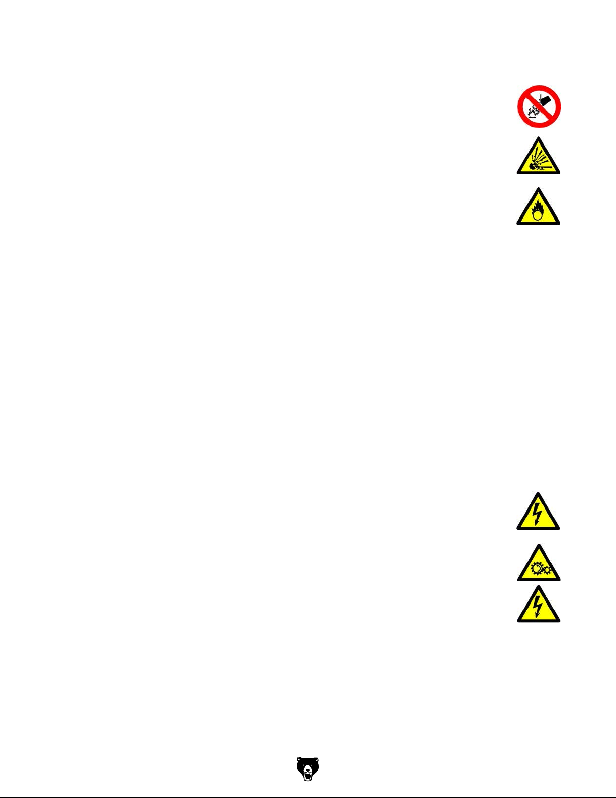
1.3.2 Other pictograms
In case of specic dangers, we replace the pictogram by
Activation forbidden! Forbidden to enter in the
Use protective boots!Use ear protection! Use protective glasses! Read the operating
general danger by a warning of injuries to hands, hazardous electrical
voltage,
Forbidden to extinguish
machine!
with water!
rotating parts.
Access forbidden!
instruction !
-10 -
Warning of suspended
loads!
Protect the environment! Contact address
Warning of oxidizing
materials!
Warning of explosive! Warning of danger of
slipping!
Model G0877 (Mfd. Since 02/19)
Page 13

1.4 Intended use
WARNING!
In the event of improper use of the CNC-machine
m there may be a risk to the staff,
m the CNC-machine and other material property of the operating company will be
endangered,
m the correct function of the CNC-machine may be affected.
The CNC-machine is designed and manufactured to be used for milling and drilling cold metals
or other non-flammable materials or materials that do not constitute a health hazard by using
commercial milling and drilling tools.
Using this machine it is possible to perform dry processing as well as processing by using cooling lubricants. See "Cooling lubricants" on page 85.
ry
The CNC-machine must only be installed and operated in a d
The CNC-machine is designed and manufactured to be used in a non-explosive environment.
approval of the company Grizzly Industrial, Inc. then the CNC-machine is being
We do not take any liability for damages caused by intended use.
We expressly point out that the guarantee or CE conformity will expire due to any constructive
technical or procedural changes which had not been performed by the company Grizzly
Industrial, Inc.
It is also part of intended use that
m the limits of performance of the CNC-machine are observed,
m the operating manual is observed,
m the inspection and maintenance instructions are observed.
and well-ventilated place.
used improperly.
Intended useIf the CNC-machine is used in any way other than described above, modified without the
WARNING!
Heaviest injuries through improper use.
It is forbidden to make any modifications or alternations to the operation values of the
CNC- machine. They could endanger the staff and cause damage to the CNC-machine.
1.5 Reasonably foreseeable misuses
Any other use as the one determined under the "Intended use" or any use beyond the
described use shall be deemed as not in conformity and is forbidden.
Any other use has to be discussed with the manufacturer.
It is
only allowed to process metal, cold and non-inflammable materials with the milling
machine.
In order to avoid misuses it is necessary to read and understand the operating instructions
before the first commissioning.
The operating staff has to be qualified.
Model G0877 (Mfd. Since 02/19)
-11-
Page 14

1.5.1 Avoiding misuses
Use of suitable cutting tools.
Adapting the speed adjustment and feed to the material and workpiece.
Clamp workpieces firmly and vibration-free.
ATTENTION!
The workpiece is always to be fixed by a machine vice, jaw chuck or by another
appropriate clamping tool such as for the clamping claws.
WARNING!
Risk of injury caused by workpieces flying off.
Clamp the workpiece in the machine vice. Make sure that the workpiece is firmly clamped in the
machine vice resp. that the machine vice is firmly clamped on the machine table.
Use cooling and lubricating agents to increase the durability of the tool and to improve the
surface quality.
Clamp the cutting tools and workpieces on clean clamping surfaces.
Sufficiently lubricate the machine.
Correctly adjust the bearing clearance and the guidings.
ATTENTION!
Do not use the drill chuck for milling tools. Never clamp a milling cutter into a drill
chuck. Use a collet chuck with collets for the end mill.
1.6 Possible dangers caused by the CNC-machine
The CNC-machine was tested for operational safety. It has been designed and built using the
latest technological advances.
Nevertheless, there is a residual risk as the CNC-machine operates with
rotating parts,
electrical voltage and currents,
compressed air,
rapid moves.
We have used construction resources and safety techniques to minimize the health risk for the
staff resulting from these hazards.
If the CNC-machine is used and maintained by the staff who are not duly qualified, there may
be a risk resulting from incorrect or unsuitable maintenance of the CNC-machine.
INFORMATION
All staff involved in assembly, commissioning, operation and maintenance, must
be duly qualified,
strictly follow these operating instructions.
During improper use
there may be a risk to the staff,
there may be a risk to the CNC-machine and other material values,
the correct function of the CNC-machine may be affected.
Always switch off the CNC-machine and disconnect it from the mains if you perform cleaning or
maintenance works.
-12-
Model G0877 (Mfd. Since 02/19)
Page 15

WARNING!
The CNC-machine may only be used with functional safety devices. Disconnect the CNCmachine immediately, whenever you detect a failure in the safety devices or when they
are not fitted!
All additional parts of the machine which had been added by the customer need to be
equipped with the prescribed safety devices.
This is your responsibility being the operating company!
1.7 Qualification of the staff
1.7.1 Target group
This manual is addressed to
the operating company,
operators having sufficient specialist knowledge,
the maintenance staff.
Therefore, the warning notes refer to both, operation and maintenance staff of the CNCmachine.
Determine clearly and explicitly who will be responsible for the different activities on the CNCmachine (operation, setting up, maintenance and repair). Please note the name of the responsible person into an operators´s log.
INFORMATION
Unclear responsibilities constitute a safety risk!
Always lock the main switch after switching off the CNC-machine. This will prevent it from being
used by unauthorized staff.
The qualifications of the staff for the different tasks are mentioned below:
Operator
The operator is instructed by the operating company about the assigned tasks and possible
risks in case of improper behaviour. Any tasks which need to be performed beyond the operation in the standard mode must only be performed by the operator if it is indicated in these
instructions and if the operating company expressively commissioned the operator.
Electrical specialist
Due to his professional training, knowledge and experience as well as his knowledge of respective standards and regulations the electrical specialist is able to perform works on the electrical
system and to recognise and avoid any possible dangers himself.
The electrical specialist is specially trained for the working environment in which he is working
and knows the relevant standards and regulations.
Specialist staff
Due to its professional training, knowledge and experience as well as his knowledge of relevant regulations the specialist staff is able to perform the assigned tasks and to recognise and
avoid any possible dangers himself.
Instructed persons
Instructed persons were instructed by the operating company about the assigned tasks and any
possible risks in case of improper behaviour.
Model G0877 (Mfd. Since 02/19)
-13-
Page 16

1.7.2 Authorized sta
INFORMATION
For working on the CNC-machine sucient expertise is required. No one must work on
the machine without having the necessary education, not even for a short while.
As aid for training and operation we recommend to use the CNC-Software SinuTrain.
SinuTrain made by Siemens is the perfect software-supplement for the CNC-machine
G0877 by Grizzly Industrial, Inc.
This training software supports the rapid training for the operation of the control Sinumerik Siemens SINUMERIK 808D. Employees having little CNC-experience can learn the basics of the
DIN-programming by using SinuTrain and are nally able to write and test programs using
SINUMERIK 808D.
Please nd SinuTrain and further information on the website of Siemens.
http://www.cnc4you.siemens.com
WARNING!
Inappropriate operation and maintenance of the CNC-machine constitutes a danger for
the sta, objects and the environment.
Only authorized sta may operate the CNC-machine !
Persons authorized to operate and maintain should be trained technical sta and instructed by
the ones who are working for the operating company and for the manufacturer.
The operating company must
m train the sta,
m instruct the sta in regular intervals (at least once a year) on
- all safety standards that apply to the CNC-machine,
- operation of the CNC-machine,
-accredited technical guideli
nes,
-possible emergency situations,
m check sta‘s state of knowledge,
m document training/instruction in a operation book,
m require sta to conrm participation in tr aining/instructions by means of a signature,
m check whether the sta is working safety- and risk-conscious and observe the operating
instructions.
The operator must
m be specially trained in handling and programming the CNC-machine,
m know and understand the program sequence and which eects the individual process
parameters will have,
m keep an operator‘s log,
m before taking the machine in operation
- have read and understood the operating instructions,
- be familiar with all safety devices and instructions.
For work on the following CNC-machine parts there are additional requirements:
m Electric components or operating materials: Must only be performed by a qualied electri-
cian or person working under the instructions and supervision of a qualied electrician.
Obligations of
the operating
company
Obligations of
the operator
Additional
requirements
regarding the
qualication
-14-
1.8 Operator positions
The operator position is in front of the CNC-machine at the sight window or on the machine
control panel.
Model G0877 (Mfd. Since 02/19)
Page 17
1.9 Safety devices
Use the CNC-machine only with properly functioning safety devices.
Stop the CNC-machine immediately if there is a failure on the safety device or if it is not functioning for any reason.
It is your responsibility!
If a safety device has been activated or has failed, the CNC-machine must only be used if you
have removed the cause of the failure,
have verified that there is no danger resulting for the staff or objects.
WARNING!
If you bypass, remove or deactivate a safety device in any other way, you are
endangering yourself and other staff working with the CNC-machine. The possible
consequences are
injuries due to tools, workpieces or fragments hereof which are flying off at high
speed,
contact with rotating or moving parts,
a fatal electrocution,
seizing of clothes.
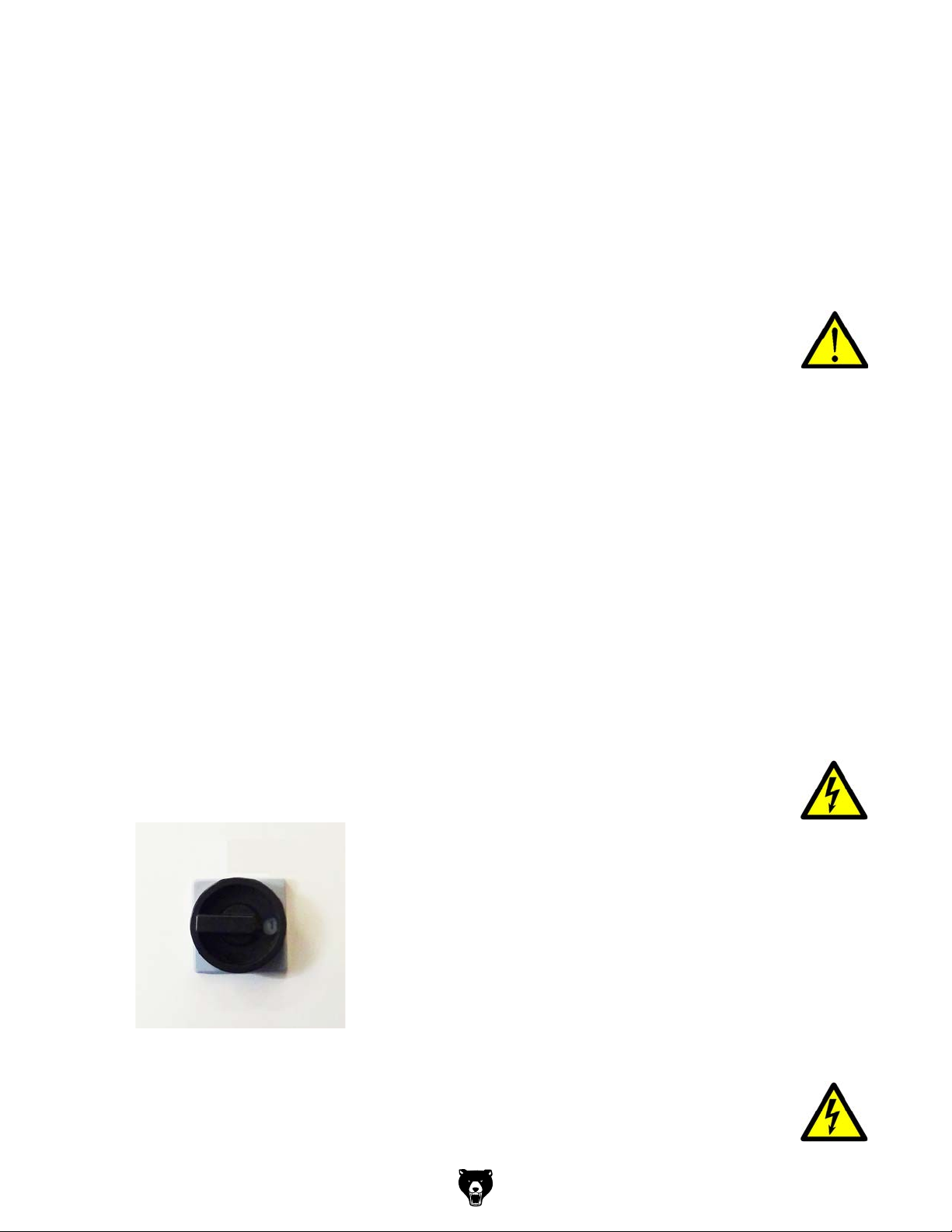
The CNC-machine includes the following safety devices:
a lockable main switch,
One EMERGENCY STOP push-button on the machine control panel, the milling head and
on the electronic handwheel,
A locked, separating protective equipment around the CNC-milling machine with sight win-
dows made of break-proof Makrolon.
Locking switch on the separating safety devices.
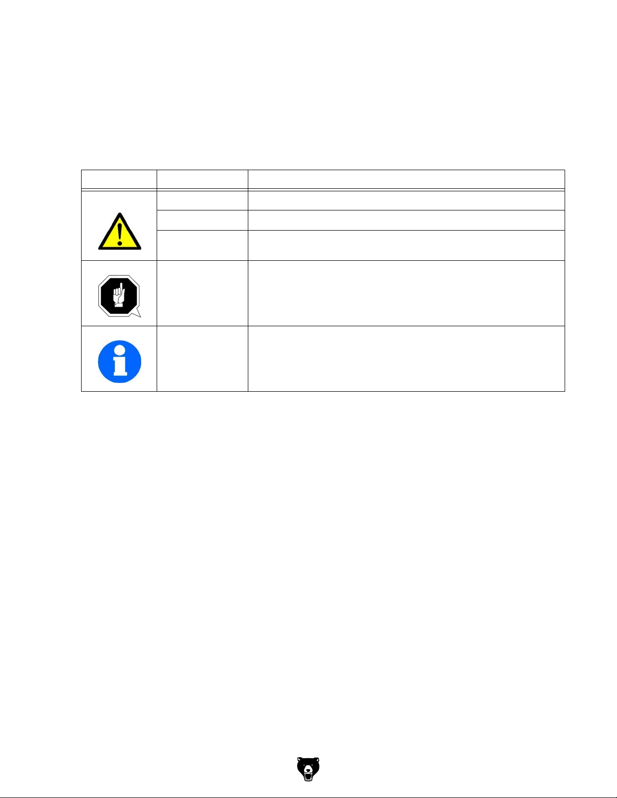
1.9.1 Lockable main switch
In the position " 0 " the lockable main switch can be secured against accidental or non-authorized switching-on by means of a padlock.
When the main switch is switched-off, the current supply is interrupted.
Except for the areas marked by the pictogram in the margin. In these areas there might be voltage, even if the main switch is switched-off.
Img.1-1: Main switch
WARNING!
Dangerous voltage even if the main switch is switched-off.
In the areas marked by pictogram in the margin, there might be voltage, even if the main switch
is switched-off.
Model G0877 (Mfd. Since 02/19)
-15-
Page 18
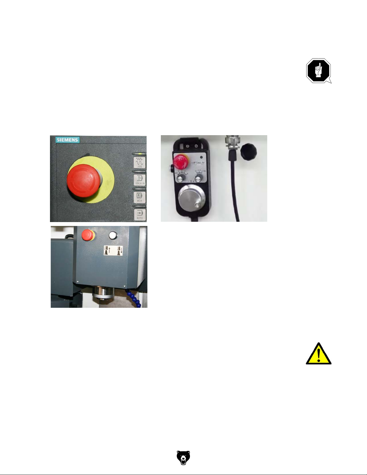
1.9.2 EMERGENCY STOP push button
ATTENTION!
The EMERGENCY STOP push button immediately stops the operation of the CNCmachine.
Press the EMERGENCY STOP push button only if there is a risk! If this push button is
actuated in order to switch off the CNC-machine in the standard operation the tool or
workpiece might get damaged.
After having actuated the EMERGENCY STOP, turn the knob of the particular push button to
the right in order to restart the machine.
-16 -
Img.1-2: Emergency-stop push button
1.9.3 Control technical protection
WARNING!
If you bypass a controller you endanger yourself and other persons working on the CNCmachine.
injuries due to tools, workpieces or fragments hereof which are flying off at high
speed,
contact with rotating parts,
a fatal electrocution,
seizing of clothes.
If you bypass a controller in exceptional cases (e.g. during electrical repairs) short term you
must continuously monitor the CNC-machine during this time.
Model G0877 (Mfd. Since 02/19)
Page 19
1.9.4 Polycarbonate windows
Polycarbonate windows which have a safety-critical function with respect to ejected parts, must
be visual inspected by the customer responsible personnel at regular intervals to guarantee the
operational safety of the CNC-machine.
Polycarbonate windows are subject to an aging process and are classified as wear parts.
The aging of polycarbonate windows can not be detected by visual inspection. It is therefore
necessary that the polycarbonate windows to be replaced after a certain time.
A longer exposure from polycarbonate windows by cutting fluids can lead to accelerated aging.
Also from the operator side can coolant agent, detergents, fats and oils or other corrosive substances cause a deterioration of the polycarbonate windows. The result is a reduced parts
retentivity of the polycarbonate windows.
"Cleaning and replacing of the polycarbonate windows“ on page 81
1.9.5 Prohibition, warning and mandatory signs
INFORMATION
All warning and mandatory signs must be legible. Check them regularly.
1.10 Safety check
Check the CNC-machine at least once per shift. Inform the person responsible immediately of
any damage, defect or change in operating function.
Check all safety devices
at the beginning of each shift (when the machine is operated continuously),
once per day (during one-shift operation),
once per week (when operated occasionally),
after every maintenance and repair work.
Check that prohibition, warning and information signs and the labels on the CNC-machine
are legible (clean them, if necessary),
are complete (replace them, if necessary).
INFORMATION
Use the following table for organizing the checks.
General check
Equipment Check OK
Protective housing Switching function, firmly bolted and not damaged
Signs, Markings Installed and legible
Sight window Check for mechanical damage (scratches, cracks).
Date: Checked by (signature):
Model G0877 (Mfd. Since 02/19)
-17-
Page 20
Functional test
KOkc ehCtnempiuqE
EMERGENCY STOP
push button
Switch cabinet cooling The cabinet cooling must be running.
Separating protective
equipment around the
CNC-machine
After actuating an EMERGENCY STOP push button the CNCmachine must be switched off.
If the protective equipment is open it must not be possible to
start program.
Date: Checked by (signature):
1.11 Personnel protective equipment
For some works you need personnel protective equipment as protective equipment.
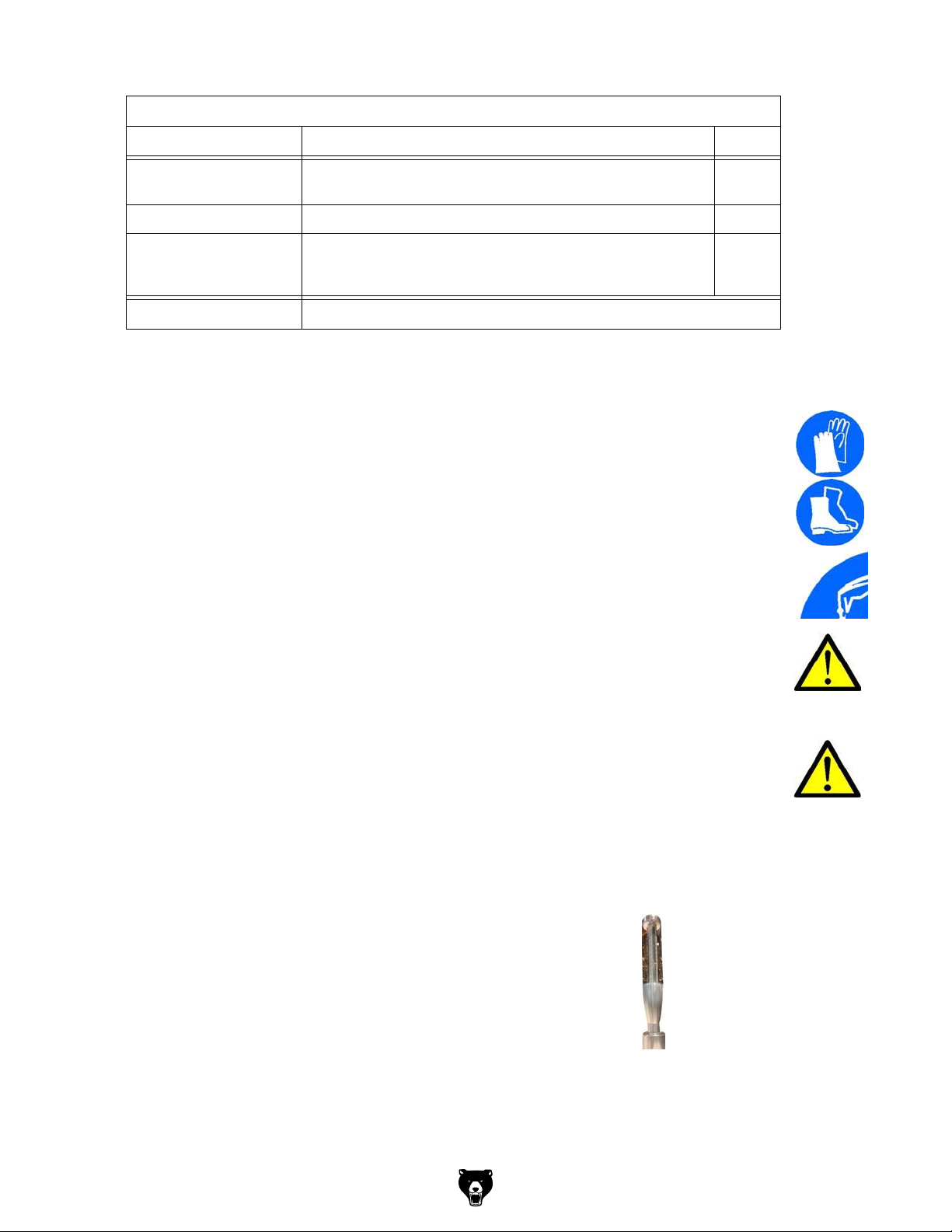
Protect your face and eyes. Wear a safety helmet with facial protection when performing works
where your face and eyes are exposed to hazards.
Use protective gloves when handling pieces or tools with sharp edges.
Use safety shoes when you assemble, disassemble or transport heavy components.
Use ear protection if the noise level (emission) in the workplace exceeds 80 dB (A).
Before starting work make sure that the prescribed personnel protective equipment is available
at the working place.
CAUTION!
Dirty or contaminated personnel protective equipment can cause diseases. Clean it each
time after use and once a week.
1.12 Safety during operation
WARNING!
Before activating the CNC-machine assure yourself that this will neither endanger other
persons nor cause damage to equipment.
Avoid any unsafe working practices:
The instructions mentioned in these operating instructions have to be strictly observed dur-
ing assembly, operation, maintenance and repair.
Do not work on the CNC-machine, if your concentration is reduced, for example, because
you are taking medication.
Stay on the CNC-machine until the program is termi-
nated.
The running program can be identified by means of
the signal lamp.
- Green light: Program run active
- Yellow light: Disorder
Img.1-3: Signal lamp
Safely and firmly clamp the workpiece before switching on the CNC-machine.
Never change the dosing of the coolant supply during operation.
Never open the sliding door of the separating protective unit when the CNC-program is run-
ning.
-18-
Model G0877 (Mfd. Since 02/19)
Page 21
WARNING!
When chipping magnesia materials (aluminium-/magnesium alloys) spontaneously
inammable or explosive particles (powder, dust, chips) might be generated which might
result in a re and/or an explosion (deagration).
Magnesium is designated as a dangerous material in the list of dangerous materials and
preparations according to Ordinance of Hazardous Substances.
In case of a re with magnesium only use appropriate and admitted extinguishing
agents. Never extinguish using water. If you extinguish burning magnesium with water it
might lead to dangerous reactions (detonating gas). Water would be decomposed in its
components hydrogen (H) and oxygen (O).
Only the following extinguishing agents are admitted:
m solid extinguishing agent of the re class D (res of metals)
m dry covering salts for magnesium
m a mixture of sand and cast chips
m argon (Ar) or nitrogen (N
)
2
If ne mist and smoke is generated in the working room, suction unites need to provided
in order to avoid the accumulation of ignitable mixtures and emissions.
We specially point out the specic dangers when working with and on the CNC-machine.
1.13 Safety during maintenance
Inform the operators in good time about any maintenance and repair works.
Report all safety relevant changes and performance details of the CNC-machine. Document all
changes, have the operating instructions updated accordingly and trai
n machine operators.
1.14 Disconnecting and securing the CNC-machine
Switch o the CNC-machine by turning o the main switch before starting any maintenance
andrepair work.
Use a padlock to prevent the switch from being turned on without authorization and keep the
key in a safe place.
All machine parts as well as all dangerous tensions are switched o.
Excepted are only the positions which are marked with the adjoining pictogram. These positions
may be live even if the main switch is switched o.
Place a warning sign on the CNC-machine.
WARNING!
Live parts and moves of machine parts can injure you or others dangerously!
Proceed with extreme care if you cannot switch o the CNC-machine by turning o the
main switch due to required works (e.g. functional control).
Model G0877 (Mfd. Since 02/19)
-19 -
Page 22

1.14.1 Using lifting equipment
WARNING!
The use of unstable lifting and load suspension gear that might break under load can
cause severe injuries or even death. Observe the accident prevention regulations issued
by your Employers Liability Insurance Association or other competent supervisory
authority, responsible for your company.
Check that the lifting equipment and load-suspension gears are of sucient load
capacity and are in perfect condition.
Fasten the loads properly.
Never walk under suspended loads!
1.14.2 Mechanical maintenance work
Remove or install protection safety devices before starting any maintenance work and re-install
them once the work has been completed.This includes:
m Covers,
m Safety indications and warning signs,
m Earth (ground) connections.
If you remove protective or safety devices, re-t them immediately after the completing the
work. Check if they are working properly!
1.15 Accident report
Inform your superiors and Grizzly Industrial, Inc. immediately in the event of
accidents, possible sources of danger and any actions which almost led to an accident (near
misses).
There are many possible causes for "near misses".
The sooner they are notied, the faster the causes can be eliminated.
INFORMATION
We point out the specic dangers when performing works with and on the CNC-machine when
describing such works.
1.16 Electrical system
Have the machine and/or the electrical equipment checked regularly, at least every six months.
Immediately eliminate all defects such as loose connections, defective wires, etc.
A second person must be present during work on live components to disconnect the power in
the event of an emergency. Immediately disconnect the CNC-machine if there are any anomalies in the power supply! "Maintenance“ on page 76
1.17 Clamping devices for workpieces and tools
ATTENTION!
Attention when taking over the existing clamping devices. Pleased check critically if the
clamping device is appropriate for your CNC-machine .
m Only use clamping devices which have a complete inherent stiness.
m Contact the manufacturer of the clamping device regarding the reuse of the clamping
devices after damages on the clamping devices due to collisions.
m Correctly insert the workpiece and make sure that the machine is proper working
condition.
-20-
Model G0877 (Mfd. Since 02/19)
Page 23

1.18 Environmental protection and water conservation
The CNC-machine is a device to produce, handle and use materials which are hazardous to
water according to the Water Resources Law.
When operating, decommissioning or disasse mbling the CNC-machine or parts hereof, please
follow the requirements of the Water Resources Law. Please nd detailed information about
this topic in the regulation about devices to treat materials which are hazardous to water.
Model G0877 (Mfd. Since 02/19)
-21-
Page 24
POWER SUPPLY
Before installing the machine, consider the availability and proximity of the required power supply
circuit. If an existing circuit does not meet the
requirements for this machine, a new circuit must
be installed. To minimize the risk of electrocution,
fire, or equipment damage, installation work and
electrical wiring must be done by an electrician or
qualified service personnel in accordance with all
applicable codes and standards.
or equipment damage
may occur if machine is
not properly grounded
and connected to power
The full-load current rating is the amperage a
machine draws at 100% of the rated output power.
On machines with multiple motors, this is the
amperage drawn by the largest motor or sum of all
motors and electrical devices that might operate
at one time during normal operations.
The full-load current is not the maximum amount
of amps that the machine will draw. If the machine
is overloaded, it will draw additional amps beyond
the full-load rating.
If the machine is overloaded for a sufficient length
of time, damage, overheating, or fire may result—
especially if connected to an undersized circuit.
To reduce the risk of these hazards, avoid overloading the machine during operation and make
sure it is connected to a power supply circuit that
meets the specified circuit requirements.
This machine is prewired to operate on a power
supply circuit that has a verified ground and meets
the following requirements:
Note: Circuit requirements in this manual apply to
a dedicated circuit—where only one machine will
be running on the circuit at a time. If machine will
be connected to a shared circuit where multiple
machines may be running at the same time, consult an electrician or qualified service personnel to
ensure circuit is properly sized for safe operation.
For your own safety and protection of
A power supply circuit includes all electrical
equipment between the breaker box or fuse panel
in the building and the machine. The power supply circuit used for this machine must be sized to
safely handle the full-load current drawn from the
machine for an extended period of time. (If this
machine is connected to a circuit protected by
fuses, use a time delay fuse marked D.)
Availability
Electrocution, fire, shock,
supply.
Full-Load Current Rating
Circuit Information
property, consult an electrician if you are
unsure about wiring practices or electrical
codes in your area.
Full-Load Current Rating at 220V .. 14 . 2 Amps
-22-
Circuit Requirements for 220V
Nominal Voltage ................... 220V, 230V, 240V
Cycle .......................................................... 60 Hz
Phase .................................................... 3-Phase
Power Supply Circuit ......................... 20 Amps
Model G0877 (Mfd. Since 02/19)
Page 25
Since this machine must be permanently connected to the power supply, an extension cord
cannot be used.
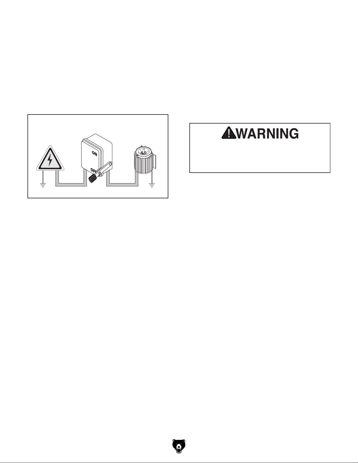
Connection Type
A permanently connected (hardwired) power supply is typically installed with wires running through
mounted and secured conduit. A disconnecting
means, such as a locking switch (see following
figure), must be provided to allow the machine
to be disconnected (isolated) from the power
supply when required. This installation must be
performed by an electrician in accordance with all
applicable electrical codes and ordinances.
process. DO NOT connect to power until
In the event of a malfunction or breakdown,
grounding provides a path of least resistance
for electrical current to reduce the risk of electric
shock. A permanently connected machine must
be connected to a grounded metal permanent wiring system; or to a system having an equipmentgrounding conductor. All grounds must be verified
and rated for the electrical requirements of the
machine. Improper grounding can increase the
risk of electric shock!
Locking
Disconnect Switch
Power
Source
Ground
Grounding Instructions
Machine
ConduitConduit
Ground
Serious injury could occur if you connect
machine to power before completing setup
instructed later in this manual.
Extension Cords
Typical setup of a permanently connected
machine.
Model G0877 (Mfd. Since 02/19)
-23-
Page 26

3 Assembly and commissioning
installation place by means of a fork-lift truck.
INFORMATION
The CNC-machine is delivered pre-assembled. It is delivered in a transport box.
3.1 Scope of delivery
Compare the delivery volume with the attached packing list.
Check the status of the CNC-machine immediately upon receipt and claim possible damages at
the last carrier also if the packing is not being damaged. In order to ensure claims towards the
freight carrier we recommend you to leave the machines, devices and packing material for the
time being in the status at which you have determined the damage or to take photos of this
status. We would like to ask you to inform us about any other claims within six days upon
receipt of the delivery.
Check if all parts are firmly seated.
3.2 Transport
WARNING!
Severe or fatal injuries may occur if the machine or parts of the machine tumble or fall
down from the forklift truck or from the transport vehicle. Follow the instructions and
information on the transport case:
Centres of gravity
Load suspension point
(Marking of positions for the load suspension
point)
Prescribed transportation position
(Marking of the top surface)
Means of transport to be used
Weights
WARNING!
Use of unstable lifting equipment and load-suspension gears that break under load can
cause very serious injury or even death.
Check that the lifting and load suspension gear has sufficient load capacity and that it is
in perfect condition.
Observe the accident prevention regulations.
Fasten the loads properly.
Never walk under suspended loads!
Check the substructure. The substructure has to bear the load.
Dismount the side parts of the wooden box.
The CNC-machine is lifted and transported with an appropriate handling device to the
-24-
Model G0877 (Mfd. Since 02/19)
Page 27
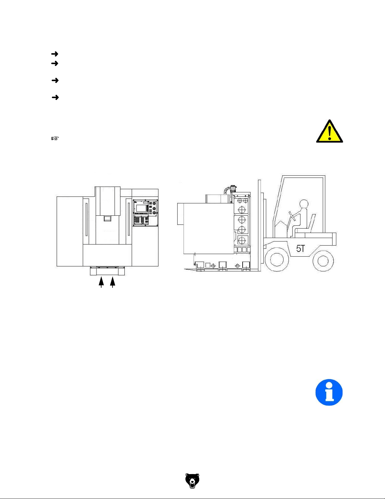
Disassemble the clamping bolts which are used to x the machine on the pallet.
Lift the CNC-machine carefully from the pallet of the transportation box by means of a crane
or a fork-lift truck.
Bring the CNC-machine with an appropriate handling device, e.g. electric pallet truck or
fork-lift truck at their rm position.
Make sure that the load attachment does not cause damage to components or paint.
WARNING!
The use of unstable lifting and load suspension gear that might break under load can
cause severe injuries or even death.
"Machine mounting“ on page 26
Img.3-1: Transporting by fork-lift truck
3.3 Installation and assembly
3.3.1 Requirements to the installation site
Organize the working area around the CNC-machine according to the local safety regulations.
The working area for operating, maintenance and repair must not be hindered. Follow the prescribed safety areas and escape routes according to environ
of the CNC-machine.
INFORMATION
The main switch of the CNC-machine must be easily accessible.
mental conditions for the operation
Model G0877 (Mfd. Since 02/19)
-25-
Page 28

3.4 Installation plan
2200
1950
Img.3-2, 3-3: Installation plan
3.4.1 Machine mounting
Anchoring-free assembly
If required, use levelling vibration- damping elements for the substructure.
Align the CNC-machine with a machine spirit level.
Check the alignment of the machine after a few days of usage.
1720
-26-
Model G0877 (Mfd. Since 02/19)
Page 29

Anchored assembly
Use the anchored assembly in order to attain a firm connection to the substructure. An
anchored assembly is always reasonable if parts are manufactured to the maximum capacity of
the CNC-machine.
Img.3-4: Drawing of the anchoring
3.4.2 Aligning the machine
Align the CNC machine on the milling table with a machine spirit level. Use the set screws
in order to perform the required height levelling.
The slope deviation of all levels must not exceed 0.03/1000mm.
Vibration and
noise insulating material
Threaded rod as anchor rod,
optionally
Shear connector cartridge M12
"Machine mounting“ on page 26
3.5 Installation and assembly
Position the machine feet included in the delivery volume below the adjusting screws of the
machine substructure.
Align the CNC-machine with a machine spirit level.
Adjusting screw
Counter nut
Machine foot
Img.3-5: Machine feet
ATTENTION!
An insufficient rigidity of the substructure leads to superposition of vibrations between
the CNC machine and the substructure (natural frequency of the components). Critical
speeds and moves in the axis with displeasing vibrations are rapidly achieved in case of
insufficient rigidity of the whole system and will lead to bad milling results.
Model G0877 (Mfd. Since 02/19)
-27-
Page 30

Check the correct alignment of the machine after a few days of usage.
3.5.1 Mounting the coolant / lubricant tank
Push the coolant / lubricant tank below the CNC machine.
Cooling lubricant tank
Img.3-6: Mounting the coolant / lubricant tank
Make sure that the coolant / lubricant tank is correctly aligned underneath the CNC
machine.
3.5.2 Assembly of the coolant / lubricant pumps
Connect the connector plugs of the coolant / lubricant pumps and of the chip conveyor, as
well as the coolant / lubricant hoses of the coolant / lubricant tank. Make sure that the plug
connections are correctly connected.
Connector plug
Coolant / lubricant hoses
-28-
Img.3-7: Connector plug
3.5.3 Corrosion protection
A corrosion protection is applied on the machine table and on the guiding surfaces for transport and storage. Remove the anti-corrosive agent from the CNC machine before rst commissioning. Therefore, we recommend you to use paran.
Model G0877 (Mfd. Since 02/19)
Page 31

3.5.4 Electrical connection
Check the fusing (fuse) of your electrical supply according to the technical instructions
regarding the total connected power of the milling machine.
Firmly connect the machine.
CAUTION!
Install the connection cable of the machine in such a way that people will not stumble
over it.
Please verify if the type of current, voltage and protection fuse correspond to the values specified. A protective earth ground wire connection must be available.
Main Fuse 16A.
Due to the design, the leakage current is greater than 3••5 mA. We ask for due attention while
executing machine tests within the framework of industrial safety guidelines.
ATTENTION!
When delivered the machine is equipped with a plug for electrical connection. It only
serves for acceptance and test purposes. In order to operate the machine it is necessary
to remove this plug and to connect the machine directly with a power supply.
Firmly connect the CNC machine to the terminal box. It is not allowed to connect the machine
using a standard 16A CEE plug, since the stray current of the frequency converter is exceeding the admissible value of 3.5mA.
ATTENTION!
Depending on the quality of the network, there is a risk of machine malfunctions under
extreme conditions. If necessary and in order to exclude retroactive effects on the
internal power supply system, the operator should install a line filter on the machine.
Therefore, at workplaces with lots of powerful consumers, it might also be necessary to
use a system for network compensation. Please consult your electricity supplier
regarding this.
ATTENTION!
Frequency converters (drive regulators) might trigger the Fl circuit breaker of your
electrical supply. In order to avoid malfunction, an Fl circuit breaker switch sensitive to
pulse current or to universal current may be required.
ATTENTION!
Ensure that all 3 phases (L1, L2, L3) and the ground wire are connected correctly.
The neutral conductor (N) of its power supply is not connected.
3.5.5 Current in the Protective Earth Ground Wire
Since a direct current may be caused by the frequency converter in the protective earthing conductor, if an upstream residual current device (ELCB / RCD) is required in the network, the following guidelines must be followed:
There are three common types of FI (ELCB / RCD):
AC - to detect AC fault currents
A - to detect AC fault currents and pulsating DC fault currents (provided the DC current
reaches zero at least once every half cycle).
B - to detect AC fault currents, pulsating DC fault currents and smooth DC residual currents.
Type AC should never be used in converters.
Type A can only be used for single-phase converters.
Type B must be used for 3-phase converters.
Model G0877 (Mfd. Since 02/19)
-29-
Page 32
When using an external EMC filter, to avoid false error shutdowns, a time delay of at least 50
ms is required. The leakage current can exceed the threshold trigger value for an error shutdown if the phases are not switched on at the same time.
Line systems
The CNC milling machine is designed for TN and TT line systems with a grounded neutral
point.
Prohibited operation
Operation on TN line systems with grounded external conductors is prohibited.
Operation on TT line systems without grounded neutral points is prohibited.
Operation on IT line systems is not permitted. In an IT line system, all of the conductors are
insulated with respect to the PE protective conductor – or connected to the PE protective conductor through an impedance. Operation on an IT line system is not permitted.
Permissible line supplies
Operation on TN and TT line systems
TN line system
The TN line system in accordance with IEC 60364-1 (2005) transmits the PE conductor to the
installation via a conductor. Generally, in a TN line system the neutral point is grounded There
are versions of a TN line supply with a grounded line the conductor, e.g. with grounded L1.
A TN line system can transfer the neutral conductor N and the PE protective conductor either
separately or combined.
TT system
In a TT line system, the transformer grounding and the installation grounding are independent
of one another. There are TT line supplies where the neutral conductor N is either transferred –
or not.
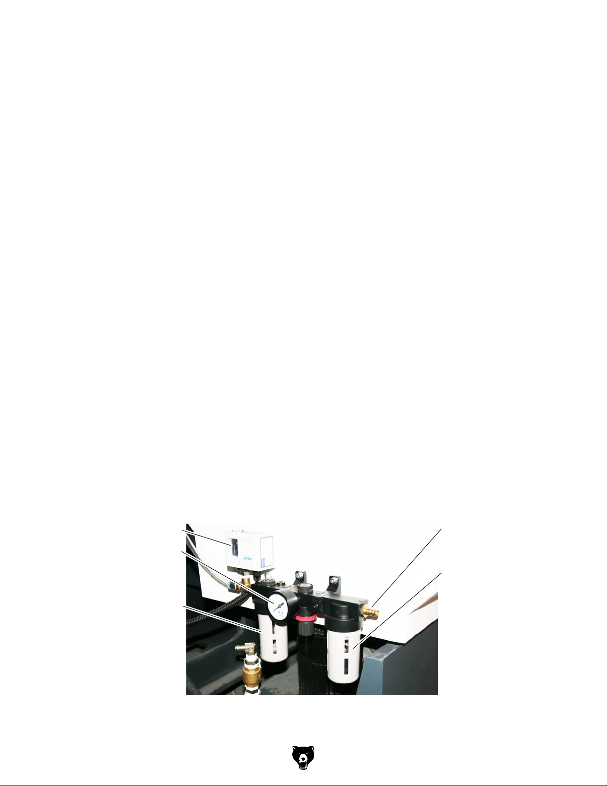
3.5.6 Connection compressed air supply
Connect the compressed air supply with at least 6.5 bars to the compressed air connection
of the compressed air maintenance unit.
Adjust a pressure of 6.3 bars using the set screw of the maintenance unit.
Air pressure switch
Manometer
Compressed air drainage
Compressed air supply
Pneumatic oiler
-30-
Img.3-8: Compressed air maintenance unit
Model G0877 (Mfd. Since 02/19)
Page 33
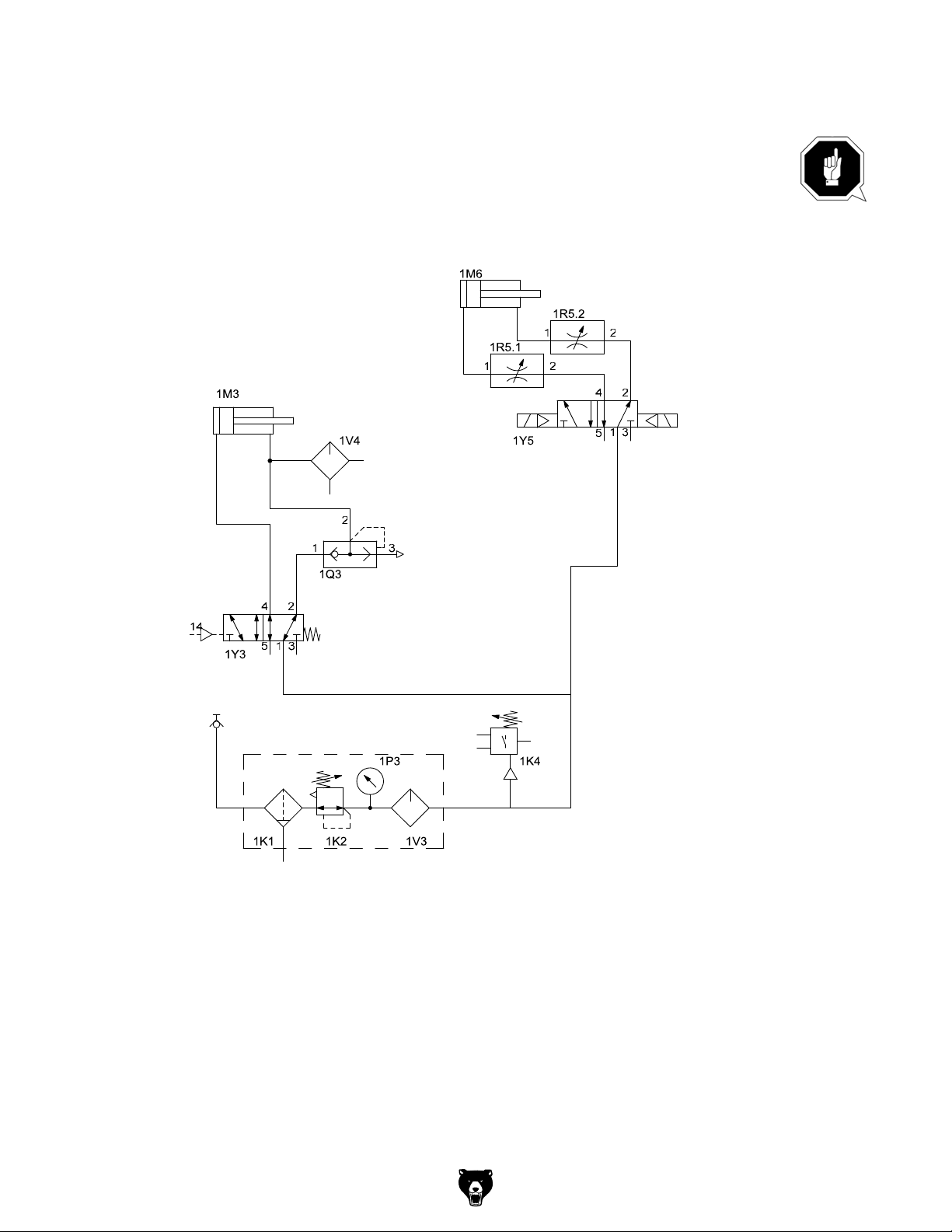
ATTENTION!
In order to ensure a failure-free operation of the machine it is necessary that the required
air pressure is continuously applied on the machine at constant quality. In case of
insufficient air supply, for instance interruptions occur during tool change.
Pneumatic scheme
Cylinder tool changer
Throttle valve
Cylinder tool clamp
Way valve
Quick exhaust
valve
Throttle valve
Way valve
Presure switch
Maintenance unit
Img.3-9: Pneumatic drawing
Model G0877 (Mfd. Since 02/19)
-31-
Page 34

3.6 First commissioning
3.6.1 Fill up coolant
INFORMATION
The CNC-machine is delivered without cooling lubricant.
Fill the coolant / lubricant tank with an appropriate cooling lubricant via the machining room
CNC- machine.
ATTENTION!
Failure of the pumps in case of dry running. The pumps are lubricated by means of the
cooling lubricant. Do not start up the pumps without cooling lubricant.
INFORMATION
Use a water soluble environmentally compliant drilling emulsion as cooling lubricant
procured from the specialised trade.
Make sure that the cooling lubricant is properly absorbed.
Respect the environment when disposing of any lubricants and coolants. Follow the
manufacturer’s disposal instructions.
INFORMATION
The CNC-milling machine is lacquered with a one-component paint. Observe this fact when
selecting your cooling lubricant.
The company Grizzly Industrial, Inc. does not assume any guarantee on subsequent
damages due to unsuitable cooling lubricants.
The flashing point of the emulsion must be higher than 140°C.
When using non water-mixable cooling lubricants (oil content > 15%) with flashing point ignitable aerosol air mixtures might develop. There is a potential danger of explosion.
"Cooling lubricants“ on page 85
-32-
Model G0877 (Mfd. Since 02/19)
Page 35
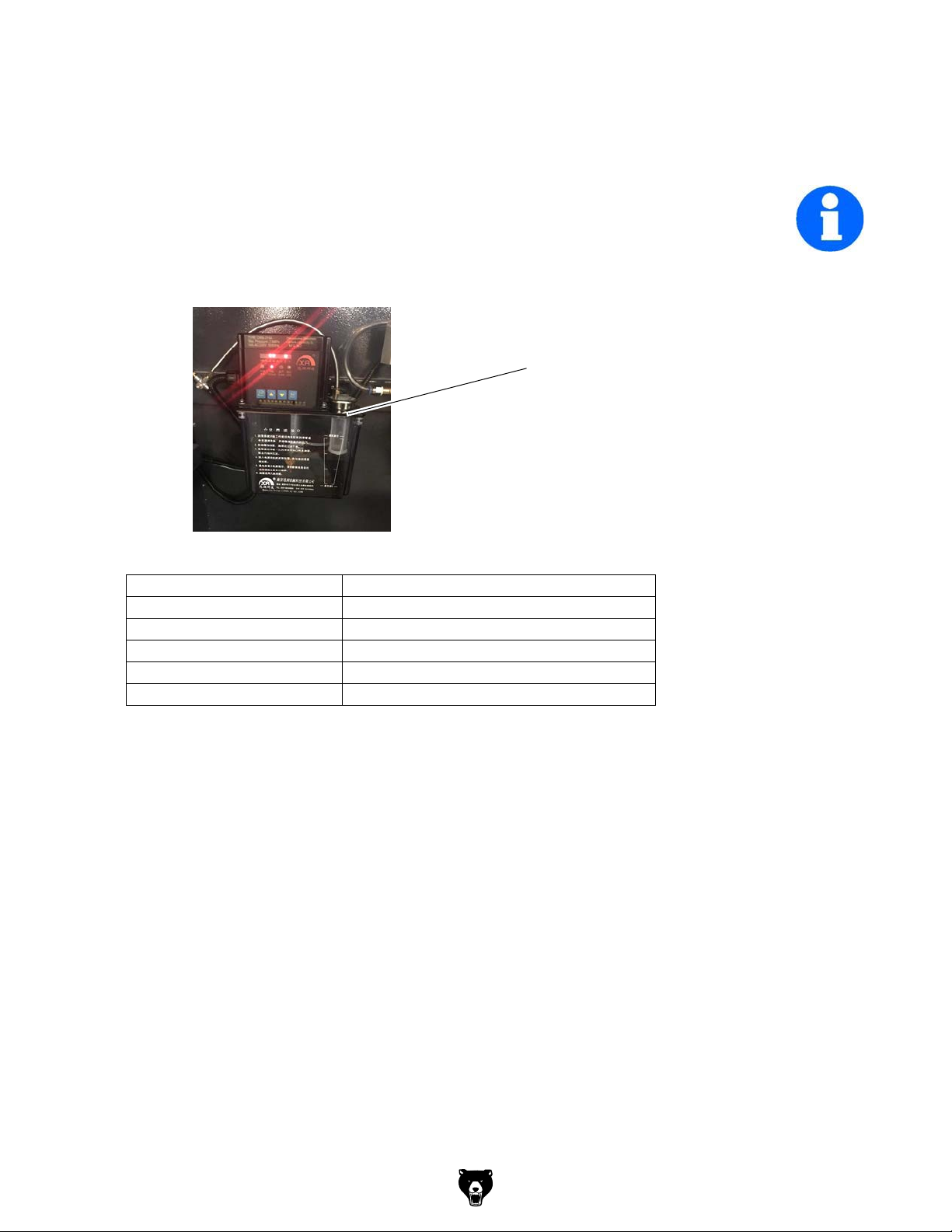
3.7 Refill central lubrication system
The CNC-machine is equipped with a central lubrication system.
INFORMATION
The CNC-milling machine is delivered without lubricating oil. The central lubrication system is
depending on the model in the working area on the column of the spindle or at other locations.
Fill the tank with lubricating oil via the filler hole.
"Cooling lubricants“ on page 85
Filler hole
Img.3-10: Central lubrication system
Type: DRB 215A
Pressure 2.5 MPa
Power 15 watt
Connection 220V ~ 50Hz
Filling capacity 2 liter
Flow rate 0.08 ml / cycle
Model G0877 (Mfd. Since 02/19)
-33-
Page 36
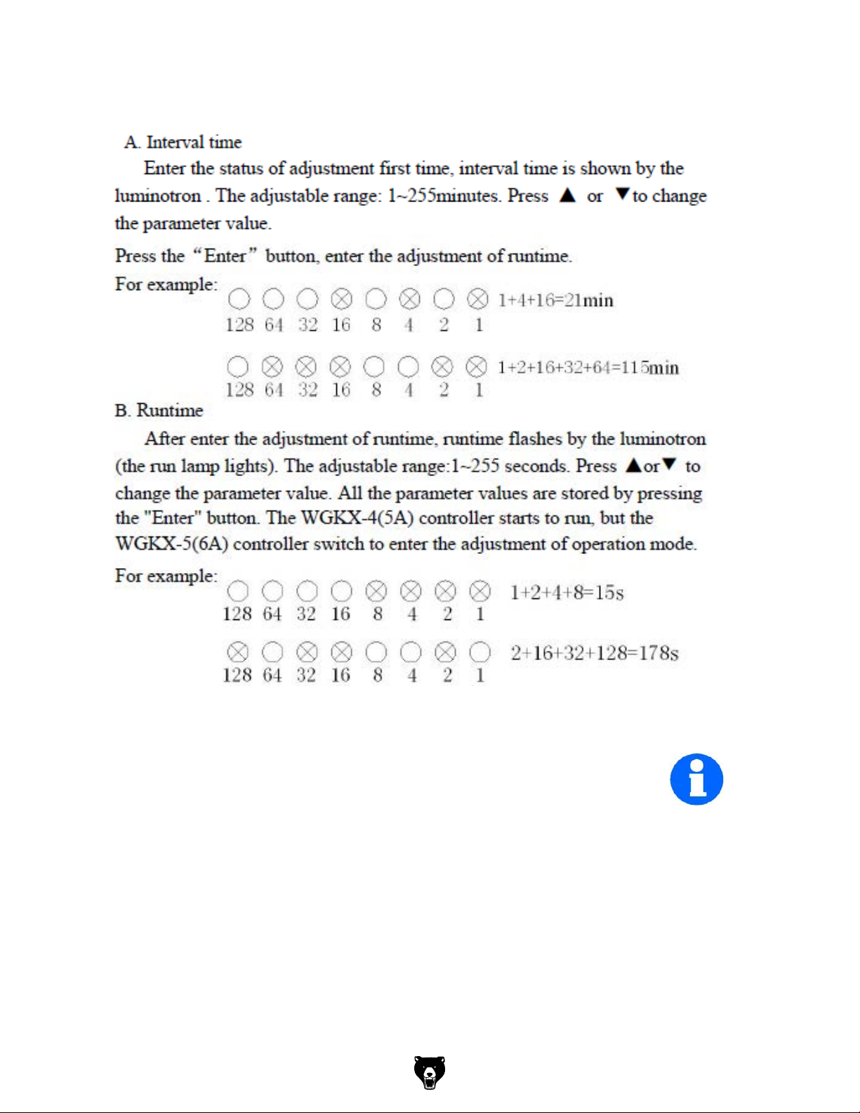
Setting the jumpers
-34-
INFORMATION
The factory setting is 120 minutes as a break between lubrication cycles and 30 seconds for the
duration of the lubricating cycle.
Model G0877 (Mfd. Since 02/19)
Page 37
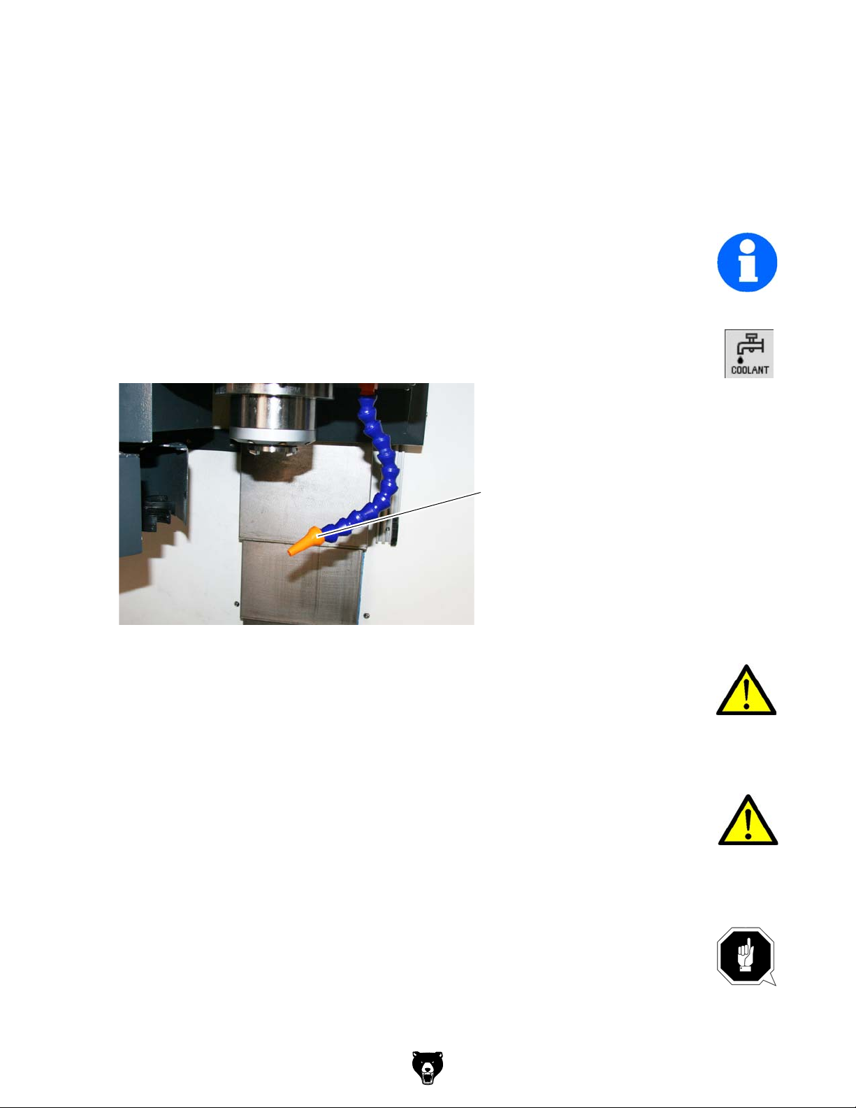
3.8 Functional test and controls
Rotation coolant pump
Check the direction of rotation of the CNC-machine.There must be a right-handed rotating
field. If the direction of rotation is wrong, exchange two of the three phase conductors. At
this, the correct direction of rotation only refers to the drive of the cooling lubricant pumps.
INFORMATION
The rotational direction of the coolant pump can not be checked in the built in state. If no coolant flows the rotational direction of the coolant pump may be wrong.
Proceeding to set the direction of rotation:
"Turning on the CNC- machine“ on page 56
Close the sliding door and turn on the coolant supply.
Check if cooling agent flows.
Coolant supply
Img.3-12: Coolant supply
WARNING!
Never change the dosing of the cooling lubricant supply when a program is running.
If no coolant is flowing and thus the rotational direction of the coolant pump may be wrong,
- first check the coolant level in the coolant tank,
- and then replace two of three phases (e.g. L1 and L2) in the control cabinet on the circuit
breaker of the engine of coolant pump against each other.
WARNING!
Swapping the phases must be performed by a qualified electrician!
Check all oil levels and filling levels of lubricants in the reservoirs.
Perform a safety test.
3.8.1 Warming up the machine
ATTENTION!
If the CNC-machine and in particular the milling spindle is immediately operated at
maximum load when it is cold it may result in damages.
If the machine is cold such as e.g. directly after having transported the machine it
should be warmed up at a spindle speed of only 500 1/min for the first 30 minutes.
Model G0877 (Mfd. Since 02/19)
-35-
Page 38

3.8.2 Save data function
The CNC control only provides a "transient working memory" losing its contents at the latest
after 3 weeks.
For this reason it is imperatively necessary to perform a data backup after commissioning the
machine respectively the machine control.
The "Save data" function saves the contents of the volatile memory into a nonvolatile memory
area.
Requirement: There is no program currently executing.
Do not carry out any operator actions while the data backup is running!
The NC and PLC data are backed up.
To call the saved data, follow these steps:
1. Press the <SELECT> key while the control system is booting.
2. In the setup menu, select "Reload saved user data".
3. Press <INPUT>.
INFORMATION
Data that have been backed up can be called again by selecting "System" > "Start-up" >
"Power-up with saved data"!
-36-
Model G0877 (Mfd. Since 02/19)
Page 39

4 General information about CNC
4.1 Compensation of geometry
It is necessary to be able to measure any currently actual position of the CNC-controlled axis in
order to perform tool moves on workpieces.The measured value is related to a machine fixed
zero position and is compared to the target position which is predefined by the programs.
Required knowledge:
coordinate systems of the machine and workpiece
reference points of the machine, tool and workpiece
type of distance measurement
options of dimensioning and dimension compensation
Basics:
For chip removal relative moves between the tool and the workpiece are required. For programming all moves are related to the resting workpiece.
4.2 Coordinate systems on CNC-machine tools
Types of coordinate systems
Coordinate systems allow the exact description of all points on a working plane, respectively in
an area.
Generally they are divided into
Cartesian coordinate system and
the polar coordinate system
4.2.1 Cartesian coordinate system
A Cartesian coordinate system also called a rectangular coordinate system possesses two
coordinate axes (two-dimensional Cartesian coordinate system) or also three coordinate axes
(three-dimensional Cartesian coordinate system) which are perpendicular to one another in
order to exactly describe the points.
On a two-dimensional Cartesian coordinate system, e.g. on the X, Y-coordinate system, each
point is clearly defined on the plane by indicating the coordinates (X,Y).
The distance from the Y-axis is called the X-coordinate and the distance from the X-axis is
called Y-coordinate. Those coordinates may possess positive or negative algebraic signs.
The three-dimensional Cartesian coordinate system is required to display and determine the
position of special workpieces, e.g. milling parts.
In order to clearly describe a point in the space, three coordinates are required which are
named according to the corresponding axes X-, Y- or Z-coordinates.
Such three-dimensional coordinate systems with positive and negative areas on the coordinate
axis allow the exact description of any locations, e.g. in the working area of a milling machine,
independent from where the zero point of the workpiece is set.
Model G0877 (Mfd. Since 02/19)
-37-
Page 40
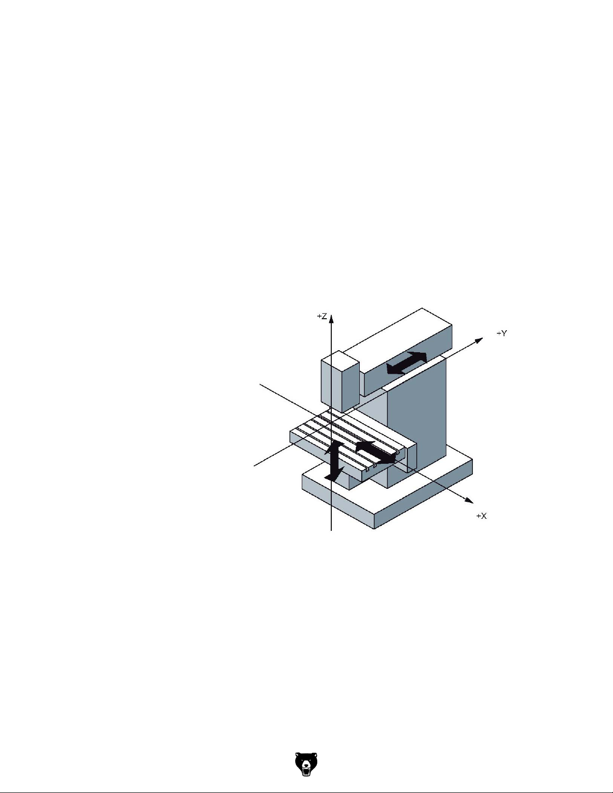
4.2.2 Polar coordinate system
In the Cartesian coordinate system a point is described by e.g. its X- and Y-coordinate. For
rotation-symmetric outlines, e.g. circular drilling images the required coordinates can only be
calculated with considerable effort.
In the polar coordinate system a point is described by means of its distance (radius r) to the
coordinate origin and its angle (a) to the defined axis. The angle (a) is related to the X-axis of
the X, Y coordinate system. In opposite direction it is negative.
4.2.3 Machine coordinate system
The machine coordinate system of the CNC machine tool is determined by the manufacturer. It
cannot be changed. The position of the origin point for the machine coordinate system, also
called machine zero point cannot be changed.
Any tool moves are generally defined in a standardized, right-handed coordinate system.
Turns from +X to +Y are created in +Z direction, which result in a right-handed screw.
Z-axis:
According to the standard it is
equal to the working spindle or
continues in positive direction
starting from the workpiece.For
milling it continues directed to the
spindle perpendicular on the
clamping surface (only for perpendicular milling machines) for several spindles one main spindle is
determined.
X-axis:
Continues horizontally and parallel to the clamping surface
for vertical Z-axis: +X to the right
for horizontal Z-axis: +X to the left
.
Img.4-1: Vertical Z-axis
Y-axis:
At a right angle to the Z- and X- axis in a way that a right-handed coordinate system is resulting
4.2.4 Workpiece coordinate system
The workpiece coordinate system is determined by the programmer. It can be changed. The
location of the origin point for this workpiece coordinate system, also called workpiece origin
point is generally user-defined.
-38-
Model G0877 (Mfd. Since 02/19)
Page 41

4.2.5 Rotary axes and secondary axes
NC machines with rotary table or swivel head
Rotary axis: A B C
Positive turn around X, Y, Z (right- hand-rule)
NC machines with several feed axes
Secondary axis: U V W
Parallel to the X-,Y-,Z-axis
4.3 NC mathematics
4.3.1 Basics of the coordinate calculation
For the CNC programming the corresponding points of the outline which is to be machined
need to be entered. In most cases if the drawing is suitable for NC purposes, it is possible to
directly transfer these coordinate points from the drawing. In some cases it may be necessary
to calculate the coordinates.
In the frame of the automation those coordinates are calculated by an NC programming system at external working places and the data are directly transferred to the machine. Therefore,
in most cases the NC programming is directly performed on the product (3D pattern) in the construction or in the process engineering department.
For the computer-aided programming the switch and path information are entered over the keyboard in the dialogue using the menu technique.
4.3.2 Parameters of a triangle
In order to calculate the missing coordinates the relations valid for a triangle are very useful.
There are several options to describe a triangle. Some of the following parameters e.g. corners,
angles or sides are being used.
4.3.3 Angle on a triangle
The angles on a triangle determine the type of triangle. Depending on the size of the individual
angles we distinguish between acute-angle, obtuse angle or rectangular triangles.
On triangles the following relation is applied:
the sum of the angles a, b and g in a triangle always amounts to 180°.
a + b + g = 180°
If two angles are known it is possible to determine the third unknown angle by means of this formula.
Rectangular triangle
The rectangular triangle has a special meaning in the analytic geometry as the sides of such a
triangle are having a definite mathematic relation to one another.
On a rectangular triangle the single sides are specially named.
The longest side is located opposite to the right angle and is named hypotenuse.
The two sides of the triangle which are forming the right angle are named cathetus.
The side opposite the angle a is named opposite leg.
The side adjacent to the angle a is named adjacent leg.
On a rectangular triangle the right angle is described by an quarter circle and a point in the
angle.
In a rectangular triangle it applies:
In a rectangular triangle you can calculate the missing leg if the other leg lengths are known. To
do so, use the Pythagorean theorem.
Model G0877 (Mfd. Since 02/19)
-39-
Page 42

The Greek Pythagoras (from about 580 to 496 B.C.) had been the first person to prove
the following mathematic relation which had later on been named the Pythagorean the-
orem.
The sum of the cathetus square is equal to the hypotenuse square and expressed as a
equation:
a² + b² = c²
a
c
b
4.4 Trigonometric functions
The trigonometric functions describe the relations between the angles and the sides of a rectangular triangle. With the help of these trigonometric functions it is possible to calculate
unknown leg lengths with an unknown angle and a known leg. It is depending on which side
and which angle are known in order to choose the appropriate trigonometric function e.g. the
sinus function, the cosine function or the tangent function.
For the calculation of unknown legs the corresponding equation needs to be transformed as
described in the following example:
Known are: the angle and the length of the adjacent leg
Looking for: the length of the opposite leg
It applies: tan alpha = opposite leg / adjacent leg
The results is:
opposite leg = adjacent leg x tan alpha
-40-
Model G0877 (Mfd. Since 02/19)
Page 43
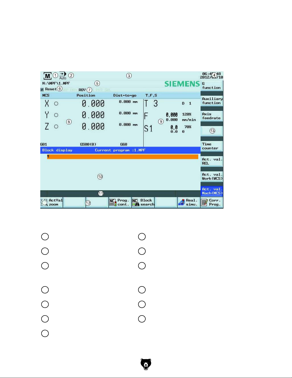
5 User interface, machine control panel
5.1 Screen arrangement
Excerpt from the manual of the operating instructions for "SINUMERIK 808D OPM Operation"
Img.5-1: Screen layout
Status area Application area
Active operating area Actual value window
1 8
Active operating mode T, F, S window
2 9
Alarm and message prompt area
3 10
Current time and date
4 11
Program file name
5 12
Program status indication
6 13
Active program control modes
7
Operating window with program block
display
Tip and softkey area
Information line
Horizontal softkey bar
Vertical softkey bar
Model G0877 (Mfd. Since 02/19)
-41-
Page 44

5.2 Elements on the PPU (Panel Processing Unit) front
Img.5-2: Panel Processing Unit
Elements on the PPU
Excerpt from the manual of the operating instructions for "SINUMERIK 808D OPM Operation"
Description
1
2
3
Vertical and horizontal softkeys
Calls specific menu functions
Return key
Returns to the next higher-level menu.
Menu extension key
No function is assigned to this key. Reserved for future use.
4
Alphabetic and numeric keys
You use these keys to enter characters or NC commands.
Holding down <SHIFT> while pressing an alphabetic or numeric key
allows you to enter the upper character shown on the key.
-42-
Model G0877 (Mfd. Since 02/19)
Page 45

Elements on the PPU
Excerpt from the manual of the operating instructions for "SINUMERIK 808D OPM Operation"
Description
5
Control keys
Shift key
Control key
Alternate key
Space key
Backspace key
Deletes a character selected to the left of the cursor.
6
Model G0877 (Mfd. Since 02/19)
Delete key
Deletes the selected file or character.
Insert key
Tab key
• Indents the cursor by several characters.
• Toggles between the input field and the selected program name.
Input key
• Confirms your entry of a value.
• Opens a directory or program.
Alarm cancel key
Cancels alarms and messages that are marked with this symbol
-43-
Page 46

Elements on the PPU
Excerpt from the manual of the operating instructions for "SINUMERIK 808D OPM Operation"
Description
7
8
9
Cursor keys
Menu function key
Opens the wizard main screen.
Help key
Calls the context-sensitive help for the selected window, alarm,
message, machine data, setting data, or end-user wizard.
Cursor keys
up/down/left/right keys
Next window key
No function is assigned to this key. Reserved for future use.
-44-
End key
Moves the cursor to the end of a line.
Page up key
Scrolls upwards on a menu screen
Page down key
Scrolls downwards on a menu screen
Selection key
• Toggles between entries in the input field.
• Enters the "Set-up menu" dialog at NC start-up.
Model G0877 (Mfd. Since 02/19)
Page 47

Elements on the PPU
Excerpt from the manual of the operating instructions for "SINUMERIK 808D OPM Operation"
Description
10
Operating area keys
Opens the "Machine" operating area
Opens the "Program" operating area
Opens the "Offset" operating area
Opens the "Program" operating area
Pressing this key opens the "Alarm" operating area.
Holding down <SHIFT> while you press this key opens the "System"
operating area.
11
12
USB interface
Status LEDs
Enables user's extension application, for example, to generate user
dialogs with the EasyXLanguage function.
For more information about this function, refer to the SINUMERIK 808D
Function Manual.
Connects to a USB device
Examples:
• Connects to an external USB memory sticker to transfer data
between the USB sticker and the CNC.
• Connects to an external USB keyboard for use as an external NC
keyboard.
LED "POK"
Lights up green: The power supply for the CNC is switched on.
LED "RDY"
Lights up green: The CNC is ready for operation.
LED "TEMP"
Unlit: The CNC temperature is within the specified range.
Lights up orange: The CNC temperature is out of range.
Model G0877 (Mfd. Since 02/19)
-45-
Page 48
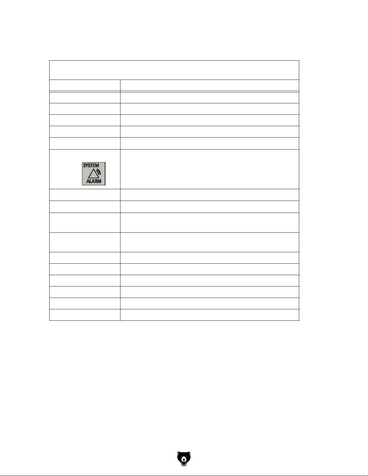
5.2.1 Key combination
Excerpt from the manual of the operating instructions for "SINUMERIK 808D OPM Operation"
Element Description
<ALT> + <X> Opens the "Machine" operating area
<ALT> + <V> Opens the "Program" operating area
<ALT> + <C> Opens the "Offset" operating area
<ALT> + <B> Opens the "Program" operating area
<ALT> + <M>
<ALT> + <N>
<SHIFT> +
<ALT> + <H>
<ALT> + <L>
<ALT> + <S>
<=>
<CTRL> + <B> Selects text in program blocks.
<CTRL> + <C> Copies the selected text.
<CTRL> + <D> Shows pre-defined slides on the screen.
<CTRL> + <P> Captures screens
<CTRL> + <R> Restarts the HMI
<CTRL> + <S> Saves start-up archives
Opens the "Alarm" operating area
Opens the "System" operating area
Calls the online help system.
Enables input of lowercase letters.
Applicable only when the user interface language is Chinese.
Calls the input method editor for entering Chinese characters.
Calls the pocket calculator. Note that this function is not applicable in
MDA mode.
-46-
Model G0877 (Mfd. Since 02/19)
Page 49
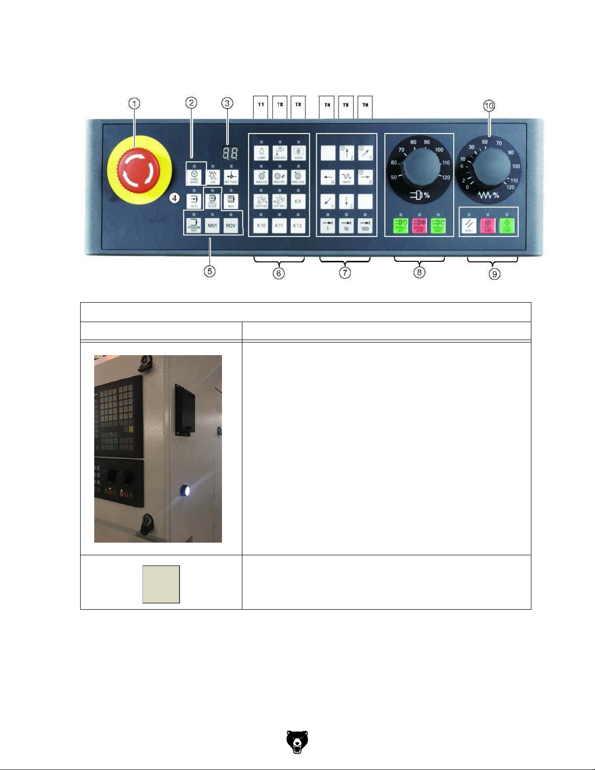
5.3 Elements on the MCP
89
1
2
11
Img.5-3: Machine Control Panel
Elements on the MCP
12
34
5
6
7
no i t cnuFt n eme l E
Drive voltage
Push-button with indicator light
• Indicator light ON, drive voltage activated
• Indicator light OFF, drive voltage deactivated
10
K11
Model G0877 (Mfd. Since 02/19)
Manual tool change
Enables or disables the manual tool change.
The manual tool change is only possible with the sliding door open.
-47-
Page 50
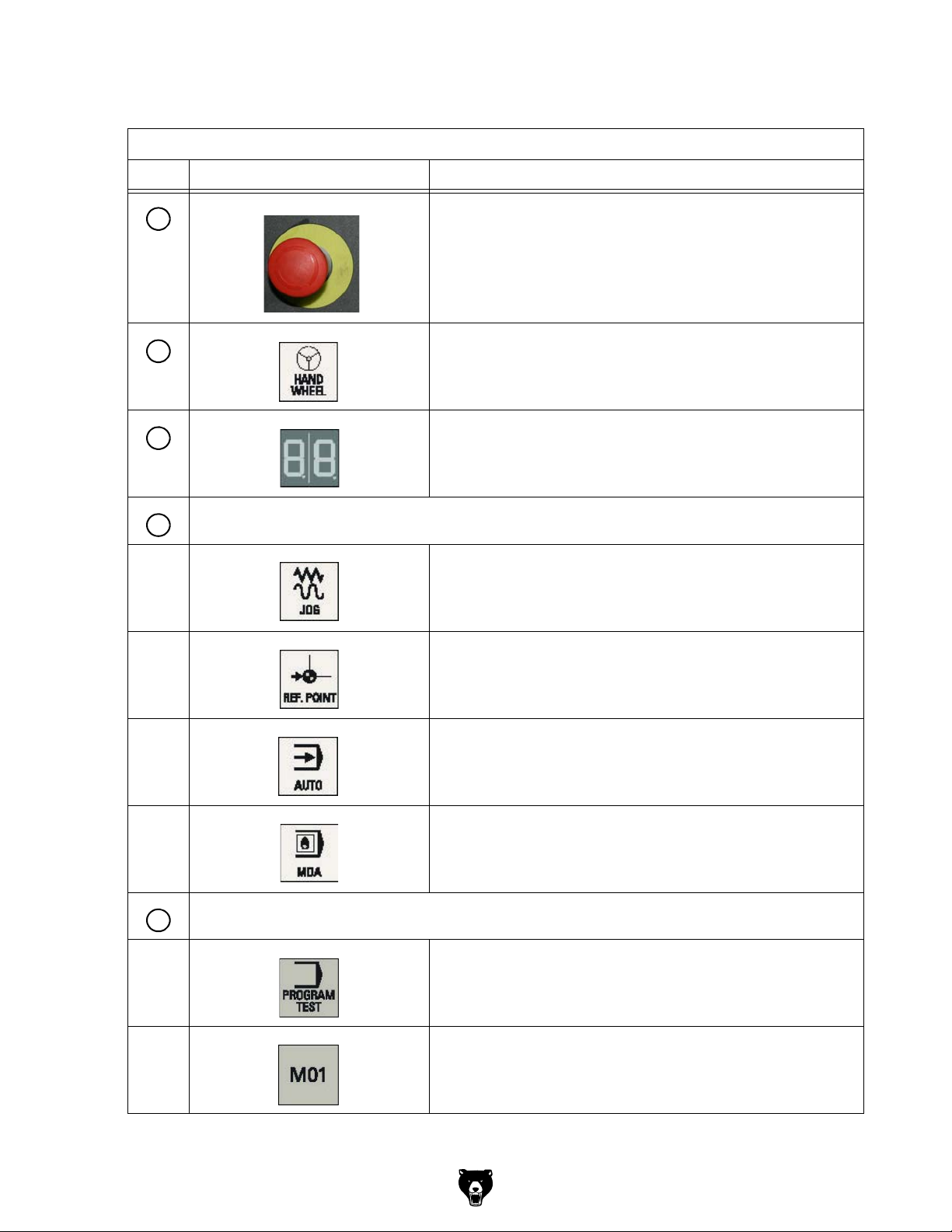
Excerpt from the manual of the operating instructions for "SINUMERIK 808D OPM Operation"
Element Description
<EMERGENCY STOP button>
1
Activate the button in situations where
• life is at risk.
• there is the danger of a machine or workpiece being damaged.
All drives will be stopped with the greatest possible braking torque.
2
3
Operating mode keys (all with LED status indicators)
4
Handwheel key (with an LED status indicator)
Controls the axis movement with external handwheels.
Tool number display
Displays the current tool number
Operating mode "JOG"
Operating mode "REF. POINT" (reference point approach)
Operating mode "AUTO" (automatic mode)
-48-
Program control keys (all with LED status indicators)
5
Operating mode "MDA"
Manual program input, automatic execution
Program test key
Disables the output of setpoints to axes and the spindle. The
control system only "simulates" the traverse movements in order to
verify the correctness of the program.
Conditional stop key
Stops the program at every block in which miscellaneous function
M01 is programmed.
Model G0877 (Mfd. Since 02/19)
Page 51
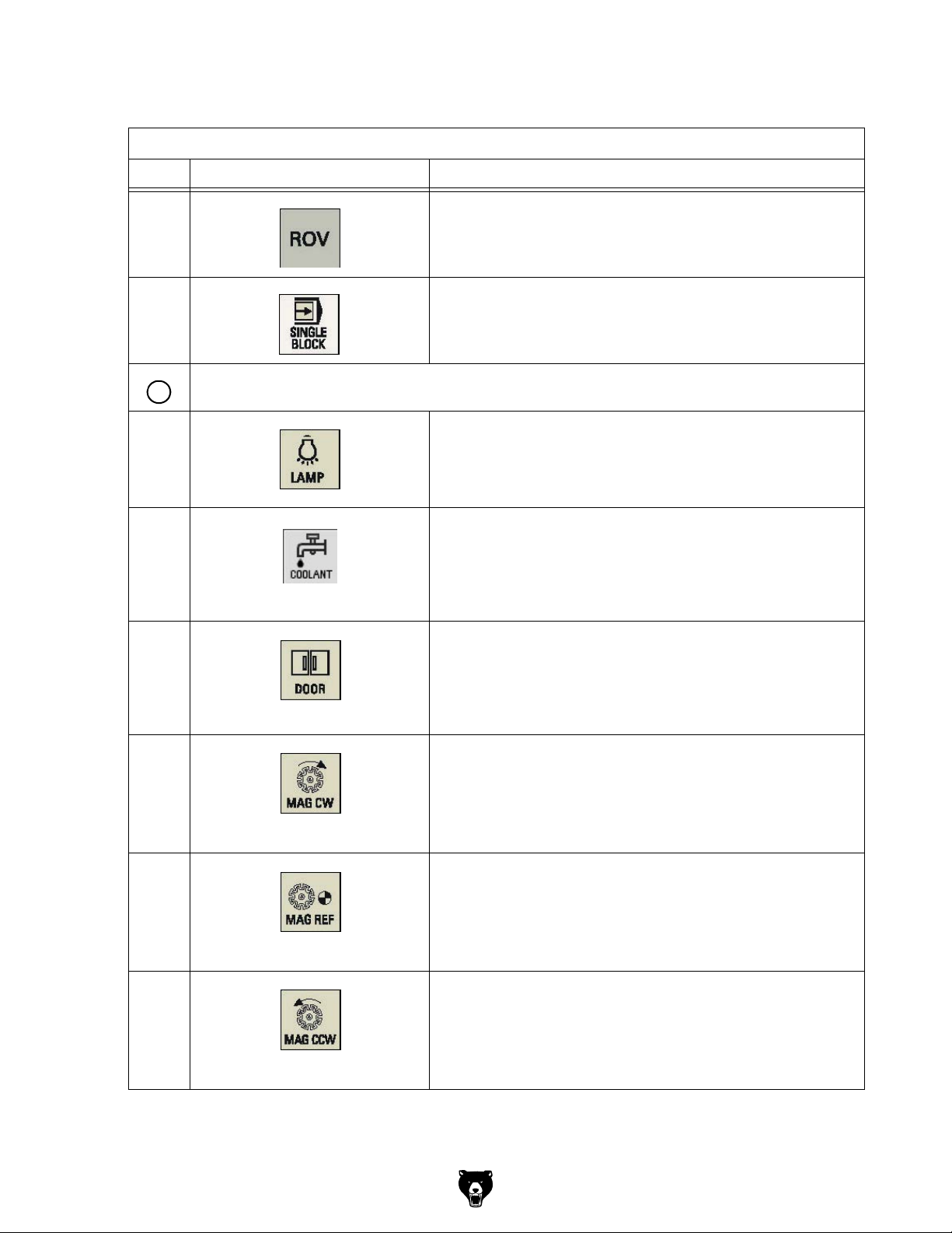
Excerpt from the manual of the operating instructions for "SINUMERIK 808D OPM Operation"
Element Description
Rapid override key
Adjusts axis feedrate override
Single block key
Activates single block execution mode
User-defined keys (all with LED status indicators)
6
Lamp control key
Pressing this in any operating mode switches on/off the lamp.
LED on: The lamp is switched on.
LED off: The lamp is switched off.
Coolant control key
Pressing this key in any operating mode switches on/off the coolant
supply.
LED on: The coolant supply is switched on.
LED off: The coolant supply is switched off.
Safety door control key
When all axes and the spindle stop operation, pressing this key
unlocks the safety door.
LED on: The safety door is unlocked.
LED on: The safety door is locked.
Clock wise magazine rotation
(active only in JOG mode)
Pressing this key rotates the magazine clockwise.
LED on: The magazine rotates clockwise.
LED off: The magazine stops clockwise rotation.
Reference point approach of the magazine
(active only in JOG mode)
Pressing this key approaches the magazine to the reference point.
LED on: The magazine is reference point approached.
LED off: The magazine is not yet referenced.
Counterclockwise magazine rotation
(active only in JOG mode)
Pressing this key rotates the magazine counterclockwise.
LED on: The magazine rotates counterclockwise.
LED off: The magazine stops counterclockwise rotation.
Model G0877 (Mfd. Since 02/19)
-49-
Page 52
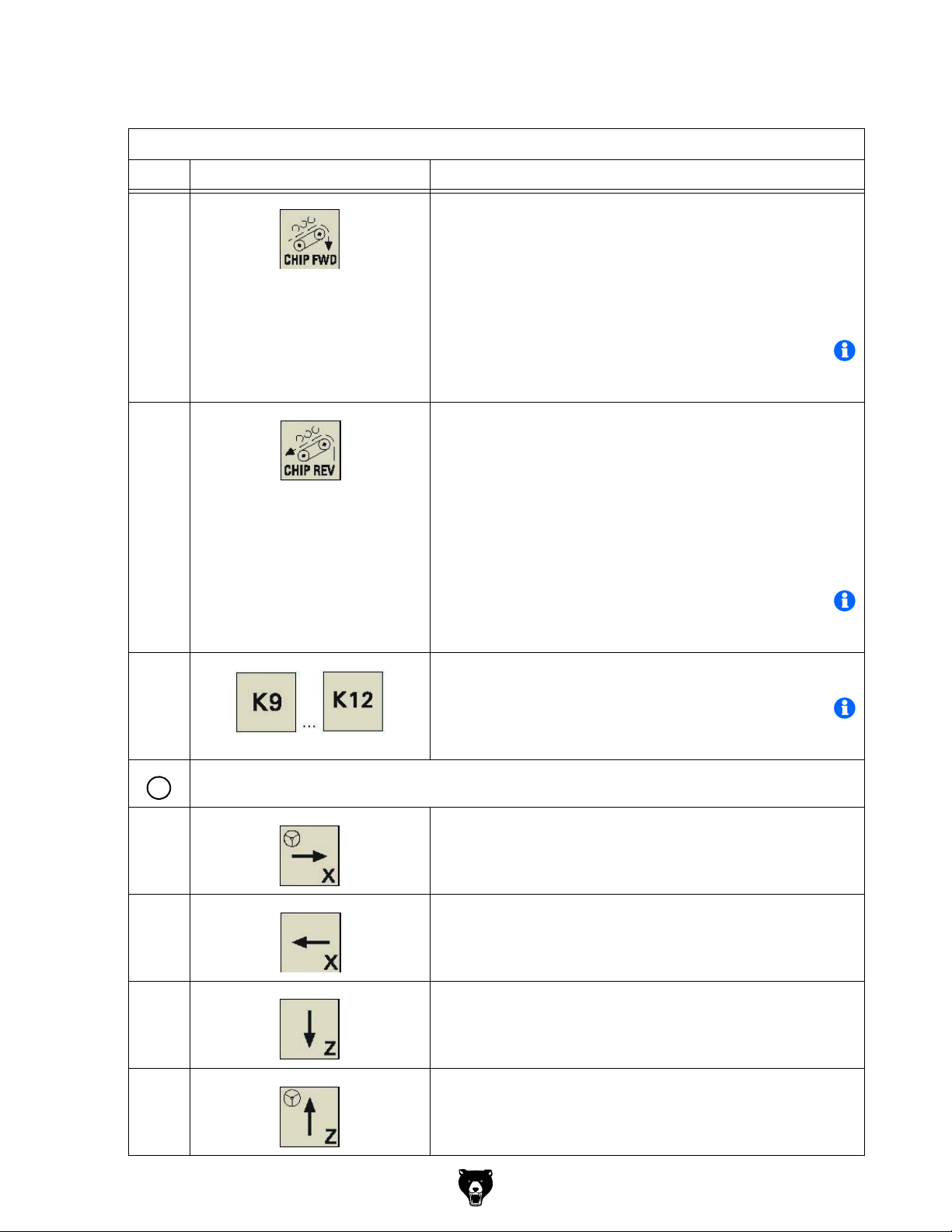
Excerpt from the manual of the operating instructions for "SINUMERIK 808D OPM Operation"
noi tpi rcseDt n eme l E
Forward rotation of the chip conveyor
(active only in JOG mode)
Pressing this key in any operating mode starts the forward rotation
of the chip conveyor.
LED on: The chip conveyor starts forward rotation.
LED off: The chip conveyor stops rotation.
INFORMATION
The machine does not have a chip conveyor. Therefore, the key has no function.
Reverse rotation of the chip conveyor
(active only in JOG mode)
Keeping pressing this key in any operating mode rotates the chip
conveyor in reverse order.
Releasing the key changes the chip conveyor to the previous
forward rotation or stop state.
LED on: The chip conveyor starts reverse rotation.
LED off: The chip conveyor stops reverse rotation.
INFORMATION
The machine does not have a chip conveyor. Therefore, the key has no function.
Axis traversing keys
7
User-defined keys
INFORMATION
The <K9> button :Mag go to spindle
The <K10> button :Mag back home
The <K11> button is associated with the manual tool
X axis key
Traverses the X axis in the positive direction.
X axis key
Traverses the X axis in the negative direction.
Z axis key
Traverses the Z axis in the negative direction.
Z axis key
Traverses the Z axis in the positive direction.
change.
-50-
Model G0877 (Mfd. Since 02/19)
Page 53

Excerpt from the manual of the operating instructions for "SINUMERIK 808D OPM Operation"
Element Description
Y axis key
Traverses the Y axis in the positive direction.
Y axis key
Traverses the Y axis in the negative direction.
Rapid traverse overlay key
Traverses the selected axis at rapid traverse speed while pressing
the relevant axis key.
Inactive key. No function is assigned to this key.
Incremental feed keys (with LED status indicators)
Sets increments desired for the axis to traverse.
Spindle control keys
8
Starts the spindle counterclockwise
Stops the spindle
Starts the spindle clockwise
Spindle speed override switch
Makes the spindle rotate at the specified speed override.
Program state keys
9
Model G0877 (Mfd. Since 02/19)
-51-
Page 54
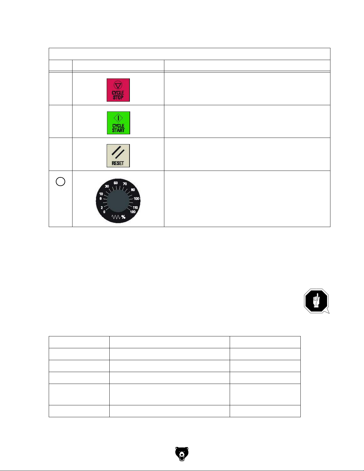
Excerpt from the manual of the operating instructions for "SINUMERIK 808D OPM Operation"
Element Description
Cycle stop key
Stops the execution of NC programs
Cycle start key
Starts the execution of NC programs
Reset key
Resets NC programs
Cancels alarms that meet the cancel criterion.
10
Feedrate override switch
Traverses the selected axis at the specified feedrate override.
5.4 Protection levels
SINUMERIK 808D provides a concept of protection levels for enabling data areas. Different
protection levels control different access rights.
The control system delivered from SIEMENS is set by default to the lowest protection level 7
(without password).
If the password is no longer known, the control system must be reinitialized with default
machine data. All passwords are then reset to default passwords for this software release.
ATTENTION!
Before you boot the control system with default machine data, make sure that you have
backed up your data; otherwise, all data is lost after rebooting with the default machine
data.
Protection level Locked by Area
0 Siemens password Siemens, reserved
1 Manufacturer password Machine manufacturers
2 Reserved
3 - 6 End-user password
(Default password: "CUSTOMER")
End users
-52-
7 No password End users
Model G0877 (Mfd. Since 02/19)
Page 55
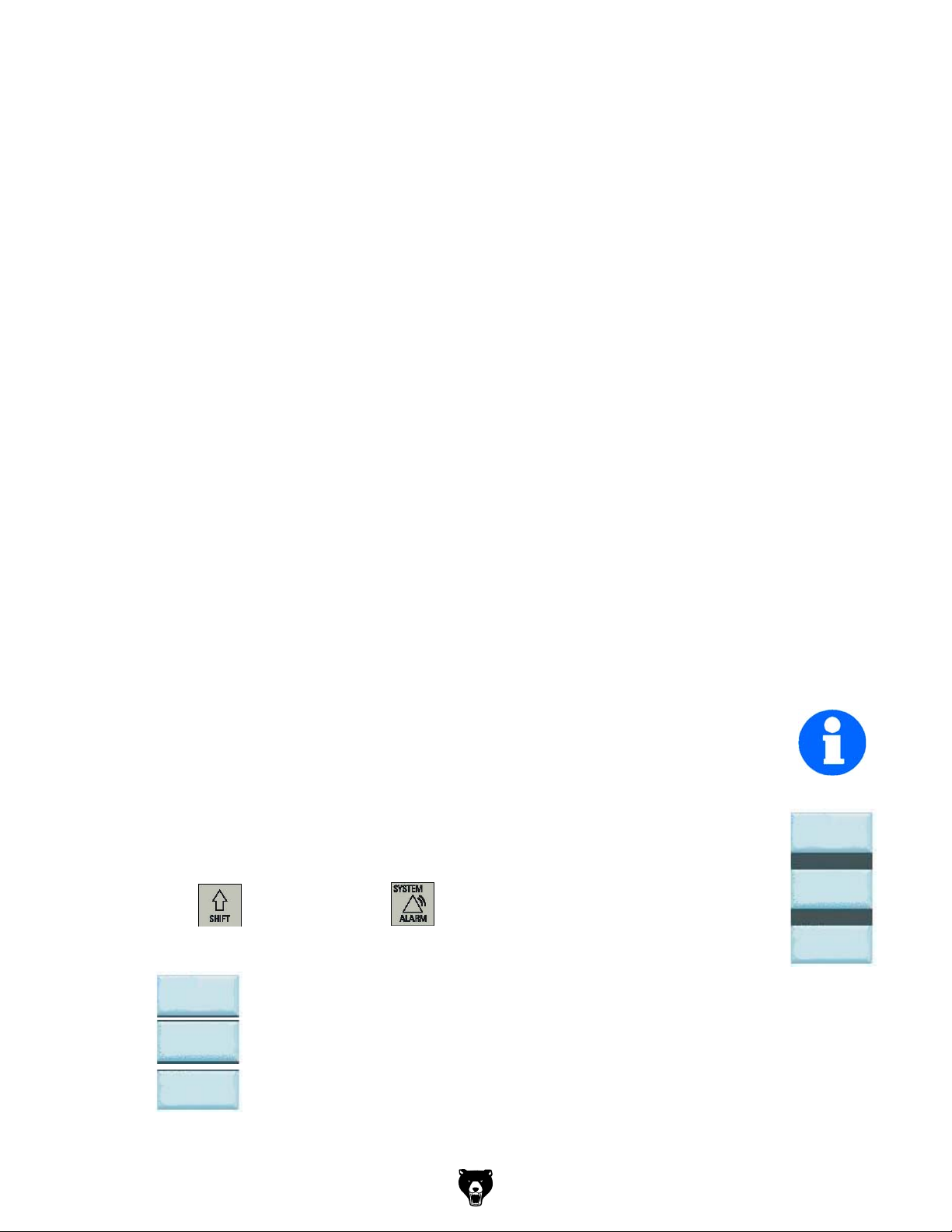
Protection level 1
Protection level 1 requires a manufacturer password. With this password entry, you can perform the following operations:
Entering or changing all machine data
Conducting NC commissioning
Protection level 3-6
Protection level 3-6 requires an end-user password. With this password entry, you can perform
the following operations:
Entering or changing part of the machine data
Editing programs
Setting offset values
Measuring tools
Protection level 7
Protection level 7 is set automatically if no password is set and no protection level interface signal is set. The protection level 7 can be set from the PLC user program after you set the bits in
the user interface.
In the menus listed below the input and modification of data depends on the set protection
level:
Tool offsets
Work offsets
Setting data
RS232 settings
Program creation / program correction
5.4.1 Passwords
INFORMATION
Usually the machine operator does not need to change the password.
5.4.2 Change passwords
Step 1
The service mode is opened with the appropriate key combination. In the service mode, the
password can be activated and deactivated.
Press Shift+ System Alarm
Step 2
Enter customer’s or manufacturer’s password.
Set
password
Change customer’s or manufacturer’s password.
Change
password
Delete customer’s or manufacturer’s password.
Delete
password
Set
password
Change
password
Delete
password
Model G0877 (Mfd. Since 02/19)
-53-
Page 56
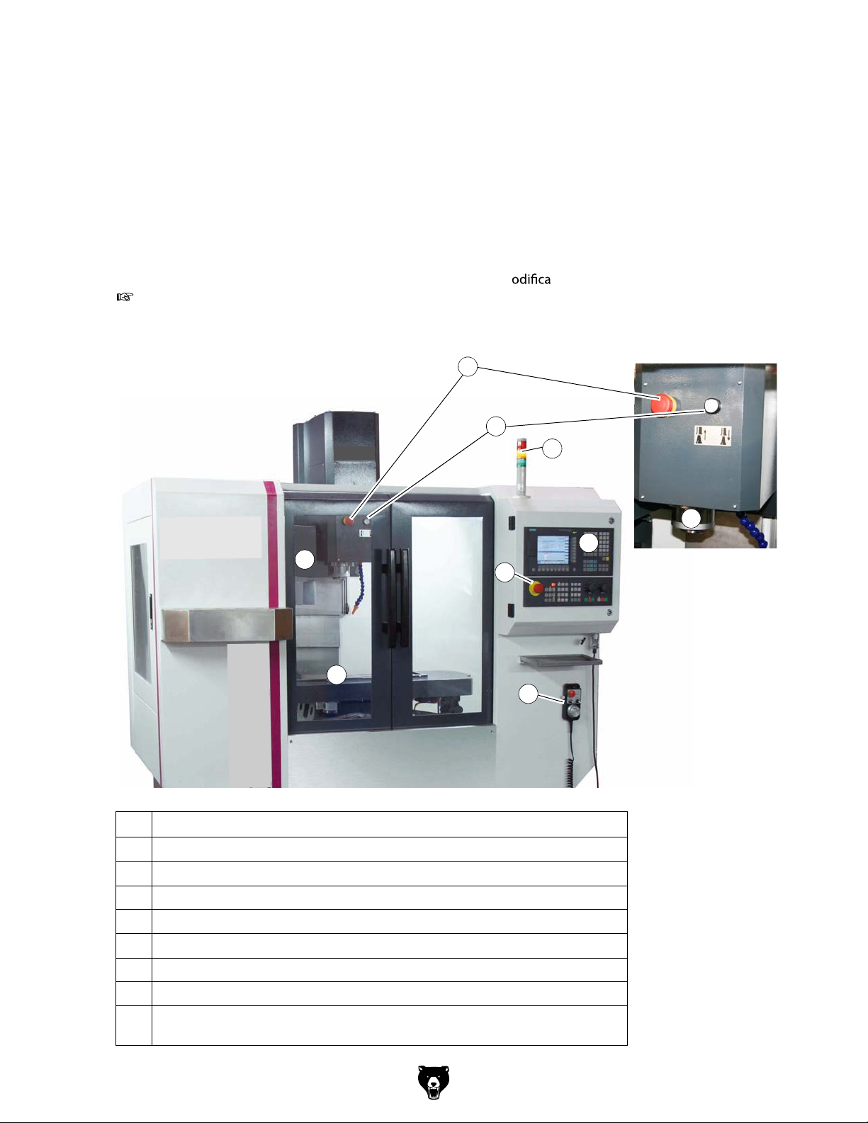
6 Operation
6.1 Safety
Commission the CNC-machine only under the following conditions:
m The CNC-machine is in proper working order.
m The CNC-machine is used as intended.
m The operating manual is followed.
m All safety devices are installed and activated.
All failures should be eliminated immediately. Stop the CNC-machine immediately in the event
of any failure in operation and make sure that it cannot be started-up accidentally or without
authorization. Notify the person responsible immediately of any m
"Additional Safety“ on page 8
6.2 Control and indicating elements
10
1
tion.
8
3
10
7
Img.6-1: Controls
No. Designation
1 To u ch-switch to release and clamp the tool.
2 Milling spindle
3 Tool change system incl. magazine disk
7 Milling table
8 Signal lamp (if the signal lamp is illuminated --> CNC- program is running)
9 Machine Control Panel
2
9
11
-54-
10 Emergency-stop push button
Handwheel for manual travelling with Emergency Stop push button and acknowl-
11
edgement button
Model G0877 (Mfd. Since 02/19)
Page 57

Signal lamp
Pos.
1
2
3
No
1
2
3
Red
Orange
Green
Lights up when activity the EMERGENCY STOP
push button
Lights up when a disturbance or in set-up operation such as
opened safety housing
Lights up in the operating mode "automatic mode" resp. "pro-
gram run"
no i t ang i seDruoloC
6.3 Operational modes
Manually controlled operation
The manually controlled operation is allowed in the operating mode "JOG" and in the operating
mode "MDA". Refer to chapter "Manual mode" of the operating instructions of "SINUMERIK
808D".
In JOG mode, you can perform the following machining operations:
Measuring tools
Measuring the workpiece
Setting parameters for face machining of a workpiece blank
Setting the spindle speed and direction, activating other M function and changing the tool,
Setting the axis positions in the relative coordinate system.
In MDA mode, you can create programs, load existing programs from directories in the "Program Manager" into the MDA buffer, or execute the current program.
Automatic mode
Refer to chapter "Setup machine" of the operating instructions for "SINUMERIK 808D".
6.4 Programming
For further working steps please proceed as described in the operating instructions "Part programming, system, programming and cycles“ for SINUMERIK 808D.
Manual resp. part programming:
For this kind of programming, the programs must be created manually and entered in the control. The direct programming in the DIN-Code is a complex method which requires lots of skills.
Nowadays this task is mostly taken over by CAD/CAM systems which directly create an operating program using a graphical user interface.
Automatic programming:
By means of the CAD/CAM program (for instance a 3D-CAD program including downstream
co-processor) construction data are transmitted (semi-)automatically to an executable program. For this kind of programming a 3D model is designed using a PC. By means of an operating sequence which is predefined by the user the motion-sequence of the machine are being
calculated. These programs are accessing the tool data base which includes all tool parameters
(speed, feed, diameter, etc.). Due to this systematic program structure the user is able to create
complete programs within shortest time without having any knowledge of the individual program
commands and its syntax.
Model G0877 (Mfd. Since 02/19)
-55-
Page 58

6.5 Operation of the machine
6.5.1 Turning on the CNC- machine
Switch on the main switch. "Lockable main switch“ on page 15
Please wait until the control is completely started.
Press the pushbutton "Drive control ON" .
Unlock the "Emergency-Stop push button" .
- on the spindle head (not visible in the picture),
- on the MCP,
- on the electronic handwheel (not visible in the picture),
1
2
Close - if not yet closed - the sliding door.
Press the pushbutton "Reset" .
3
2
Img.6-2: Operating area
1
3
-56-
Model G0877 (Mfd. Since 02/19)
Page 59
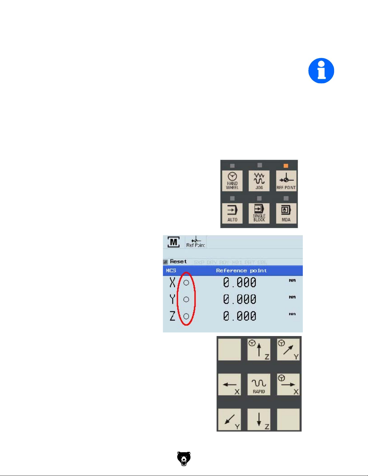
6.5.2 Reference point approach after turning on
INFORMATION
If your machine is configure with ABS encoder (808D ADVANCED), you do not need to
reference the axis of the machine.
If your machine is fitted with INC encoder (808D), after power on, the machine must first
be referenced!
After turning on, the machine must first be referenced. Without existing reference
points (machine zero points) you cannot start and run programs in the control.
With the beginning of the reference point approach the axes should be located in a
central position as possible.
The following information indicated serve as preliminary information. Further
information can be found in the Siemens manual.
After switching on, the machine is in the mode reference
point approach area, the LED on the <REF POINT> button
lights.
As long as the axes are not referenced,
the symbol (circle) between the axis and
the corresponding value is displayed.
The axes are referenced with the
"axis traversing keys."
Make sure that the "feed override switch"
is not set to "zero".
+
+
Model G0877 (Mfd. Since 02/19)
+
-57-
Page 60

Traverse each axis to the machine
zero point until the referenced symbol is shown on the respective axis.
Once the axis approaches the reference point, the referenced symbol must
shown next to the axis.
After returning to the "JOG" mode, the
axes can be moved manually. Use the Increment button to
specify the increment, or press the <JOG> button again to
stop the increment again.
If possible, read the upcoming mes-
sages on the display, remove the
error messages, such as e.g. insuffi-
cient compressed air, ....
Default values for example should
apply for the feed rate in the "JOG"
mode, be entered on the side of the
standard values .
Press the button <OFFSET> to get
to the settings.
For the following working steps,
please proceed as described in
„Operation and programming“ of the
Siemens SINUMERIK 808D Operation instructions.
-58-
Model G0877 (Mfd. Since 02/19)
Page 61

6.5.3 Using the electronic handwheel
The electronic handwheel can always be used when
the CNC- machine is referenced,
the LED on the button <HANDWHEEL> lights up.
Press the button <HANDWHEEL> on the machine control panel to use the electronic handwheel.
Pos.
No
4
5
1
2
3
Designation Description
1
2
3
4
5
Rotary switch
Rotary switch
Hand wheel
<EMERGENCY
STOP button>
Push button resp.
acknowledge-
ment button
Selector switch to control the individual
Selector switch for the feed speed (3
Handwheel to travel the individual
The EMERGENCY STOP push button
switches off the CNC- machine.
In the setting mode it is necessary to
actuate the acknowledgement button
in order to expressively allow the
movement of the individual axes.
axis.
stages).
axes.
WARNING!
A manual movement of axes with open door is not possible. The machine has no
acknowledgement button to allow movement of axes with open slide door.
The lock switch on the slide door may only be unlocked for maintenance and repair
work.
Model G0877 (Mfd. Since 02/19)
-59-
Page 62

6.5.4 Inserting a tool
INFORMATION
Before you can run a CNC program, at least one tool must have been created and
measured in the tool memory.
Change over to the mode <JOG>.
Press the "Offset" key on the
machine control panel.
Press the "Tool list" softkey
For the following working steps,
please proceed as described in
„Operation and programming“ of
the Siemens SINUMERIK 808D
Operation instructions.
6.5.5 Clamping workpiece and setting workpiece datum
ATTENTION!
The workpiece is always to be fixed by a machine vice, jaw chuck or by another
appropriate clamping tool such as for the clamping claws.
When setting and using already created programs observe the safety clearance in order
to avoid collisions with the selected clamping means.
WARNING!
Risk of injury caused by workpieces flying off.
Clamp the workpiece in the machine
vice.
Workpiece
Make sure that the workpiece is firmly
clamped in the vise.
6.5.6 Manual tool change
ATTENTION!
Hold your tool if there is a tool inserted in the spindle.
Machine vice
Img.6-3: Clamping the workpiece
Press the push button "Open/Close door" and open the sliding door.
Check that the LED on the pushbutton <K11>lights up.
Press - if necessary - the pushbutton <K11>. The manual tool change
is thereby enabled again.
-60-
Model G0877 (Mfd. Since 02/19)
Page 63

Press the pushbutton "manual tool change" to loosen or to clamp the tool.
Pushbutton manual
tool change
Img.6-4: Spindle head
6.5.7 Turning o the CNC- machine
Push the EMERGENCY STOP push button.
For a long-term standstill of the CNC machine switch it o at the main switch.
6.6 Operational modes
Manually controlled operation
The manually controlled operation is allowed in the operating mode "JOG" and in the operating
mode "MDA". Refer to "Manual mode" of the operating instructions of "SINUMERIK
808D".
Automatic mode
Refer to "Setup machine" of the operating instructions for "SINUMERIK 808D".
6.7 Programming
For further working steps please proceed as described in the operating instructions "Part pro-
gramming, system, programming an d cycles“ for SINUMERIK 808D.
Manual resp. part programming:
For this kind of programming, the programs must be created manually and entered in the control. The direct programming in the DIN-Code is a complex method which requires lots of skills.
Nowadays this task is mostly taken over by CAD/CAM systems which directly create an operating program using a graphical user interface.
Automatic programming:
By means of the CAD/CAM program (for instance a 3D-CAD program including downstream
co-processor) construction data are transmitted (semi-)automatically to an executable program. For this kind of programming a 3D model is designed using a PC. By means of an operating sequence which is predened by the user the motion-sequence
calculated. These programs are accessing the tool data base which includes all tool parameters
(speed, feed, diameter, etc.). Due to this systematic program structure the user is able to create
complete programs within shortest time without having any knowledge of the individual program
commands and its syntax.
of the machine are being
Model G0877 (Mfd. Since 02/19)
-61-
Page 64
DIN Code and ISO Code:
Use the procedure for switching or activating the programming language in the manual operation and programming of the "SINUMERIK 808D".
6.8 Start program
Adjusting the dosing for the coolant supply on the spindle head before starting the program.
Any change in the dosing must only be performed during the setup operation. The requirement
of coolant supply is switched on over your CNC- programs.
WARNING!
Never change the dosing of the cooling lubricant supply and never seize into the
machine when a program is running.
CAUTION!
Before starting the programs you have to close the sliding door of the separating
protective equipment.
Completely close the separating protective equipment.
Change over to the mode "AUTO/MDA"
For the following working steps, please proceed as described in „Operation and
programming“ of the Siemens "SINUMERIK 808D" Operation instructions.
-62-
Model G0877 (Mfd. Since 02/19)
Page 65

6.9 Central lubrication system
The CNC-machine is equipped with a central lubrication system.
The lubricating system is used to maintain an oil lm on the slideways, the bearings, the ledges
and the ball screws and to reduce their wear.
In case of a failure or a fault in the central lubricating system a stick-slip eect may occur. This
eect describes the jerky sliding of solids moving opposite one another. For instance: creaking
doors and rattling windscreen wipers.
6.10 Data interfaces and current collection
When connecting data interfaces make sure that the data cable runs to the interface of the controlwithin shortest possible distance. The cable routing can be conducte d along the measuring
system lines. However the cable in the switch cabinet must never be routed nearby the drive
apparatuses of the NC axis or the frequency converter itself. Errors occur during data transfer
due to electromagnetic radiation (EMC-problems).
The control is equipped with the following data interfaces. They are located laterally on the control panel of the CNC-maschine:
m RJ45 plug- in connection
m USB connection
m Connection for power supply
6.11 Selecting the speed
The correct speed is an important factor for m illing. The speed determines the cutting speed by
which the cutting edges cut the material. By selecting the correct cutting speed, the service life
of the tool is increased and the working result is optimized.
The optimum cutting speed mainly depends on the materi
tools (milling cutters) made of hard metal or ceramic insert it is possible to work with higher
speeds than with tools made of high-alloy high speed steel (HSS). You will achieve the correct
cutting speed by selecting the correct speed.
In order to determine the correct cutting speed for your tool and for the material to be cut you
may refer to the following standard values or a table reference book.
al and on the material of the tool. With
The required speed is calculated as follows:
V
------------
n
=
�
x d
-1
n = speed in min
V = cutting speed in m/min (meter per minute)
d = tool diameter in m (Meter)
(revolutions per minute)
Model G0877 (Mfd. Since 02/19)
-63-
Page 66
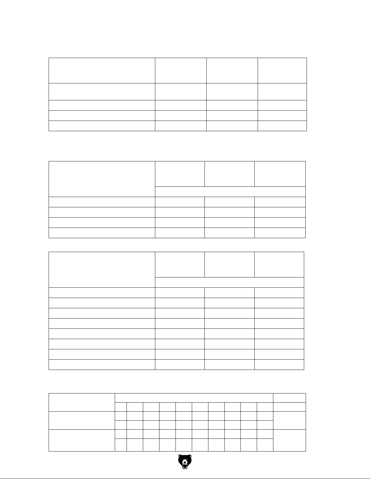
6.11.1 Standard values for cutting speeds
[ m/min ] with high-speed steel and hard metal in conventional milling.
Tool Steel Grey cast iron
Al
alloy
age-hardened
Plain mill and side milling cutters [ m/min
]
Relieved form cutters [ m/min ] 15 - 24 10 - 20 150 - 250
Inserted -tooth cutter with SS [ m/min ] 15 - 30 12 - 25 200 - 300
Inserted-tooth cutter with HM [ m/min ] 100 - 200 30 - 100 300 - 400
10 - 25 10 - 22 150 - 350
The results are the following standard values for speeds in dependence of the
milling cutter diameter, cutter type and material.
Tool diameter
[ mm ] Peripheral and
Steel
10 - 25 m/min
Grey cast iron
10 - 22 m/min
Al alloy
age-hardened
150 - 350 m/min
side milling cutters
Speed [ min-1 ]
35 91 - 227 91 - 200 1365 - 3185
40 80 - 199 80 - 175 1195 - 2790
45 71 - 177 71 - 156 1062 - 2470
50 64 - 159 64 - 140 955 - 2230
Tool diameter
[ mm ]
Steel
15 - 24 m/min
Grey cast iron
10 - 20 m/min
Al alloy
cured 150 - 250
m/min
form cutters
Speed [ min-1 ]
4 1194 - 1911 796 - 1592 11900 - 19000
5 955 - 1529 637 - 1274 9550 - 15900
-64-
6 796 - 1274 531 - 1062 7900 - 13200
8 597 - 955 398 - 796 5900 - 9900
10 478 - 764 318 - 637 4700 - 7900
12 398 - 637 265 - 531 3900 - 6600
14 341 - 546 227 - 455 3400 - 5600
16 299 - 478 199 - 398 2900 - 4900
6.11.2 Standard values for speeds with HSS – Eco – twist drilling
Material
Steel, unalloyed,
up to 600 N/mm
Structural steel, alloyed,
quenched and subsequently
drawn, up to 900N/mm
2
2
2345678910
1)
5600 3550 2800 2240 2000 1600 1400 1250 1120
n
2)
0.04 0.063 0.08 0.10 0.125 0.125 0.16 0.16 0.20
f
1)
3150 2000 1600 1250 1000 900 800 710 630
n
2)
0.032 0.05 0.063 0.08 0.10 0.10 0.125 0.125 0.16
f
Drill diameter Cooling
Model G0877 (Mfd. Since 02/19)
3)
E
E/oil
Page 67
Structural steel, alloyed,
quenched and subsequently
drawn, up to 1200 N/mm
Stainless steels up to 900 N/
2
mm
e.g. X5CrNi1810
1)
: Speed [ n ] in r/min
2)
: Feed [ f ] in mm/r
3)
: Cooling: E = Emulsion; oil = cutting oil
The above mentioned indications are standard values. In some cases it may be advanta-
1)
2500 1600 1250 1000 800 710 630 560 500
n
2)
0.032 0.04 0.05 0.063 0.08 0.10 0.10 0.125 0.125
f
2
1)
2000 1250 1000 800 630 500 500 400 400
n
2)
0.032 0.05 0.063 0.08 0.10 0.10 0.125 0.125 0.16
f
Oil
Oil
geous to increase or decrease these values.
When drilling a cooling or lubricating agent should be used.
For stainless materials (e.g. VA – or NIRO steel sheets) do not center as the material would
compact and the drill bit will become rapidly blunt.
The workpieces need to be tensed in flexibly and stably (vice, screw clamp).
INFORMATION
High temperatures are generated at the tip of the tool by the occurring friction heat. The tool
should be cooled during the milling process. By cooling with an appropriate coolant lubricant
you will achieve a better working result and longer durability of the tool.
INFORMATION
Use a water soluble environmentally compliant emulsion as cooling agent procured from the
specialized trade.
Make sure that the cooling agent is properly retrieved. Respect the environment when disposing of any lubricants and coolants. Follow the manufacturer’s disposal instructions.
INFORMATION
The CNC milling machine is lacquered with a one-component paint. Observe this fact when
selecting your cooling lubricant.
Model G0877 (Mfd. Since 02/19)
-65-
Page 68
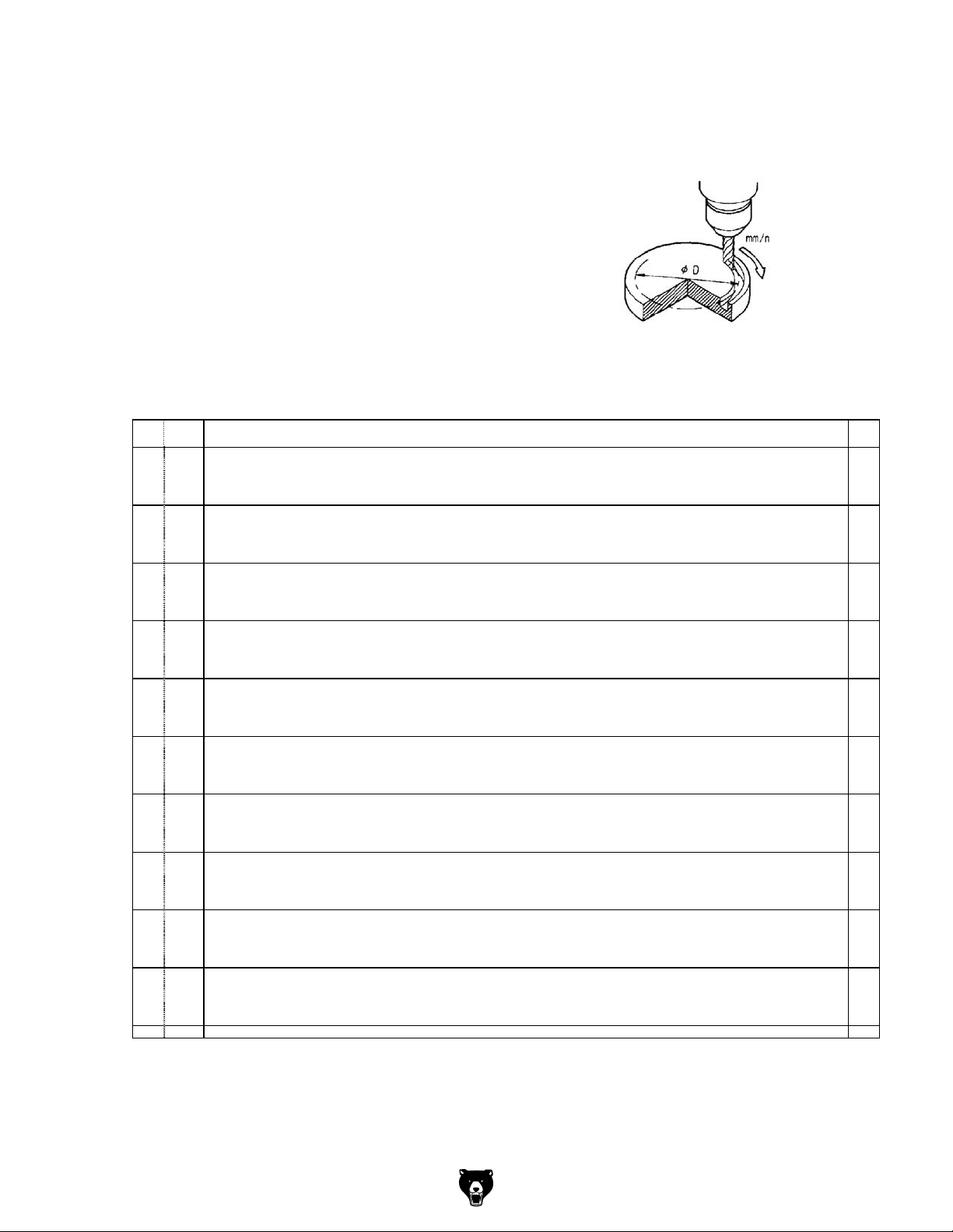
6.12 CNC Rotary Table cutting speed chart
The direct instruction system with the F-code is used for instructions
of speeds of CNC rotary table (moving in degrees per minute), as follows.
Example:
F100 = 100 °/min = 0.28 R.P.M
Relation between a feed of tool and a circular arc dia.
D at a time of cutting is listed in the following chart.
How to use the chart:
When an outer periphery of work D = 160 mm is to be cut by end milling at a speed of 110 mm/
min. F value obtained as f = 80 from 111 mm / min. corresponding to D = 160 mm at the topmost line.
RPM
F R.P.M. 30 40 50 60 80 100 120 140 160 180 200 230 250 300 400
F 10 0.03 3 4 5 6 8 9 11 13 15 17 19 22 24 28 38 47 F 10
F 20 0.06 6 8 9 11 15 19 23 26 30 34 38 43 47 57 75 94 F 20
F 30 0.08 8 10 13 15 20 25 30 35 40 45 50 58 63 75 100 125 F 30
F 40 0.11 10 14 17 21 28 35 42 48 55 62 69 80 87 104 138 173 F 40
F 50 0.14 13 18 22 26 35 44 53 62 70 79 88 101 110 132 176 220 F 50
F 60 0.16 15 20 25 30 40 50 60 70 80 91 101 116 126 151 201 252 F 60
F 70 0.19 18 24 30 36 48 60 72 84 96 107 119 137 149 179 239 299 F 70
F 80 0.22 21 28 35 41 55 69 83 97 111 124 138 159 173 207 276 346 F 80
F 90 0.25 24 31 39 47 63 79 94 110 126 141 157 181 196 236 314 393 F90
F100 0.28 26 35 44 53 70 88 106 123 141 158 176 202 220 264 352 440 F100
F110 0.31 29 39 49 58 78 97 117 136 156 175 195 224 244 292 390 487 F110
F120 0.33 31 41 52 62 83 104 124 145 166 187 207 239 259 311 415 519 F120
F130 0.36 34 45 57 68 90 113 136 158 181 204 226 260 283 339 452 566 F130
F140 0.39 37 49 61 74 98 123 147 172 196 221 245 282 306 368 490 613 F140
F150 0.42 40 53 66 79 106 132 158 185 211 237 264 303 330 396 528 660 F150
F160 0.44 41 55 69 83 111 138 166 193 221 249 276 318 346 415 553 691 F160
F170 0.47 44 59 74 89 118 148 177 207 236 266 295 340 369 443 591 739 F170
F180 0.50 47 63 79 94 126 157 189 220 251 283 314 361 393 471 628 786 F180
F190 0.53 50 67 83 100 133 167 200 233 266 300 333 383 416 500 666 833 F190
F200 0.55 52 69 86 104 138 173 207 242 276 311 346 397 432 518 691 864 F200
F210 0.58 55 73 91 109 146 182 219 255 292 328 364 419 456 547 729 911 F210
F220 0.61 57 77 96 115 153 192 230 268 307 345 383 441 479 575 766 958 F220
F230 0.64 60 80 101 121 161 201 241 282 322 362 402 463 503 603 804 1006 F230
F240 0.67 63 84 105 126 168 211 253 295 337 379 421 484 526 632 842 1053 F240
F250 0.69 65 87 108 130 173 217 260 304 347 390 434 499 542 650 867 1084 F250
F260 0.72 68 90 113 136 181 226 271 317 362 407 452 520 566 679 905 1131 F260
F270 0.75 71 94 118 141 188 236 283 330 377 424 471 542 589 707 942 1178 F270
F280 0.77 73 97 121 145 194 242 290 339 387 435 484 556 605 726 968 1210 F280
F290 0.81 76 102 127 153 204 255 305 356 407 458 509 585 636 764 1018 1273 F290
F300 0.83 78 104 130 156 209 261 313 365 417 469 522 600 652 782 1043 1304 F300
F310 0.86 81 108 135 162 216 270 324 378 432 486 540 624 676 811 1081 1351 F310
F320 0.90 85 113 141 170 226 283 339 396 452 509 565 650 707 848 1131 1414 F320
F330 0.92 87 116 145 173 231 289 347 405 462 520 578 665 723 867 1156 1445 F330
F340 0.94 89 118 148 177 236 295 354 413 472 531 591 679 738 886 1181 1476 F340
F350 0.97 91 122 152 183 244 305 366 427 488 548 609 701 762 914 1219 1524 F350
F360 1.00 94 126 157 189 251 314 377 440 503 566 628 723 786 943 1257 1571 F360
F370 1.03 97 129 162 194 259 324 388 458 518 582 647 744 809 971 1294 1618 F370
F380 1.06 100 133 167 200 266 333 400 466 533 599 666 766 833 999 1332 1665 F380
F390 1.08 102 136 170 204 271 339 407 475 543 611 679 780 848 1018 1357 1697 F390
F400 1.11 105 139 174 209 279 349 418 488 558 628 697 802 872 1046 1395 1744 F400
F410 1.14 107 143 179 215 286 358 430 501 573 645 716 824 895 1074 1432 1791 F410
F420 1.17 110 147 184 221 294 368 441 515 588 662 735 845 919 1103 1470 1838 F420
F430 1.19 112 150 187 224 299 374 449 523 598 673 743 860 935 1121 1495 1869 F430
F440 1.22 115 153 192 230 307 383 460 537 613 690 767 882 958 1150 1533 1917 F440
F450 1.25 118 157 196 236 314 398 471 550 628 707 785 908 982 1178 1571 1964 F450
F460 1.28 121 161 201 241 322 402 483 563 643 724 804 925 1005 1206 1608 2011 F460
F470 1.31 123 165 206 247 329 412 494 576 658 741 823 946 1029 1235 1646 2058 F470
F480 1.33 125 167 209 251 334 418 501 585 668 752 836 961 1045 1253 1671 2089 F480
F490 1.36 128 171 214 256 342 427 513 598 684 769 855 983 1068 1282 1709 2187 F490
F500 1.39 131 175 218 262 349 437 524 611 699 786 873 1004 1092 1310 1747 2184 F500
30 40 50 60 80 100 120 140 160 180 200 230 250 300 400 500
D
500
F
-66-
Model G0877 (Mfd. Since 02/19)
Page 69
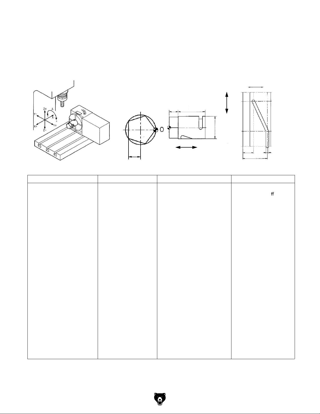
6.12.1 Example of programming
The workpiece is 50mm in diameter.
1 Cutting 5 face by 20 mm at end of the workpiece.
2 Helix cutting.
20
60
360°
A
300°
A
100°
0°
30
70
20
Ø 50
X
X
NC program 1 Description NC program 2 Description
N1
T1 M06
M11
G90 G00 A36. M10
G90 G45 G00 X7.5 Y25
G43 Z100. S500 H1
M03
Z5
G01 Z-5. F100 M08
Y-12.
Y-25. F2000
M11
G00 A108. M10
G01 Y12. F100
Y25. F2000
M11
G100 A180. M10
G01 Y-12. F100
Y-25. F2000
M11
G00 A252. M10
G01 Y12. F100
End mill 25mm
Rotary table unclamp
Rotary table clamp
ø
Rotary +36
°
G90 G00 Z100. M05
G90 G54 G00 X70. Y0. G43
G01 Z-6. F100 M08
M10
G01 Y-12. F100
Y-25. F2000
Z5. M09
M11
G00 A0.
G91 G28 Z0. G49
N2
T2 M06
Z100. S3000 H2
M03
A100.
X30. A300.
G90 G00 Z5. M05
M09
M10
G91 G28 Z0. G49
M30
Coolant o
Spindle stop
End mill 8mm
8
ø
Model G0877 (Mfd. Since 02/19)
-67-
Page 70

7 M - Code list, M functions
7.1 M-function for milling machines according to PAL
No. Function
No. Function
M00 Programmed stop
M01 Selected stop
M02 Program end
M03 Starting the milling spindle in positive direction
(clockwise)
M31
M32
M33
M34
M35
M04 Starting the milling spindle in negative direction
(anti-clockwise)
M05 Stopping the milling spindle
M06 Automatic tool change
M07
M08 Cooling lubricant pump ON
M09 Cooling lubricant pump OFF
M10
M11
M12
M13
M14
M15
M16
M17 Return from subroutine
M18
M19 Spindle stop in defined limit position
M20 Program end with resetting (Reset)
M21
M22
M23
M24
M25
M26
M27
M28
M29
M30
Tool magazine reaching to the spindle postion
Tool magazine reaching to the original postion
Clamp workpiece
Loosen workpiece
M36
M37
M38
M39
M40
M41
M42
M43
M44
M45
M46
M47
M48
M49
M50
M51
M52
M53
M54
M55
M56
M57
M58
M59
M60 Workpiece change
M61
M62
M63
-68-
Model G0877 (Mfd. Since 02/19)
Page 71

No. Function
No. Function
M64
M65
M66
M67
M68
M69
M70
M71
M72
M73
M74
M75
M76
M77
M78
M79
M99
M80
M81
M82
M83
M84
M85
M86
M87
M88
M89
M90
M91
M92
M93
M94
M95
M96
M97
M98
Model G0877 (Mfd. Since 02/19)
-69-
Page 72

7.2 G functions to PAL
G0 Travelling in rapid traverse
G1 Linear interpolation during process
G2 Circular interpolation clockwise
G3 Circular interpolation anti-clockwise
G4 Retention period
G9 Accurate stop
G10 Travelling in rapid feed in polar coordi-
nates
G11 Linear interpolation with polar coordinates
G12 Circular interpolation clockwise with polar
coordinates
G13 Circular interpolation anti-clockwise with
polar coordinates
G45 Linear tangential travelling on a contour
G46 Linear tangential travelling off the contour
G64 Accurate stop off
-70 -
Model G0877 (Mfd. Since 02/19)
Page 73

8 Notes, messages and error messages
All messages and alarms are displayed in plain text on the control panel. The alarm text contains the date, time and a suitable symbol for the cancel criterion.
Alarms and messages are displayed separately according to the following criteria:
Alarms and messages in the part program.
Alarms and messages from the PLC and alarms and messages that concern the machine.
The description of the alarms and messages in the part program and other alarms and messages from the PLC are in the Siemens manual.
Number Message
700000 User alarm 01
700001 The manual mode of MGZ is active
700002 Air pressure is not enough (bigger 0.6 Mpa)
700003 The door is open
700004 The power sequence is wrong(1L\2L\3L, change
700005 User alarm 06
700006 User alarm 07
700007 User alarm 08
700008 User alarm 09
700009 User alarm 10
700010 HHU is active
700011 Not able to lock tool in expected time
700012 Spindle in braking progress
700013 Operation while chuck is not closed
700014 Gear-change time out
700015 Gear level position error
700016 DRIVES NOT READY
700017 Operation chuck when sp. or part prog. is running
700018 COOLING MOTOR OVERLOAD
700019 COOLANT LIQUID POSITION IN LOW LEVEL
700020 LUBRICATING MOTOR OVERLOAD
700021 LUBRICANT LIQUID POSITION IN LOW LEVEL
700022 TURRET MOTOR OVERLOAD
700023 PROGRAMMED TOOL NUM. > MAX. TURRET NUMBER
700024 Max. tool number setting error
700025 NO POSITION SIGNALS FROM TURRET
700026 Not able to find expected tool in monitor time
700027 APPROACH REF.POINT AGAIN AFTER ROT. MONITORING
Model G0877 (Mfd. Since 02/19)
-71-
Page 74

Number Message
700028 Tool is not locked
700029 Reminding information for 1st service plan
700030 Alarm for 1st service plan
700031 Magazin not in spindle pos. or original pos.
700032 Magazin in spindle pos. and original pos.
700033 Magazine turn key when magazine or sp. not ready
700034 Block search, tool in spindle <> programmed tool
700035 Spindle not reach tool-release pos. in time
700036 Spindle not reach tool-lock pos. in time
700037 Do not move MGZ when Z axis under the tool change pos.
700038 User alarm 39
700039 Turn magazine when alarm or tool not retracted
700040 Start ATC when Z axis not in tool change pos.
700041 Move Z axis when ATC not in original position
700042 ATC not finish action in monitor time
700043 Change tool when magazine not in run mode
700044 Magazine motor overload
700045 ATC motor overload
700046 User alarm 47
700047 User alarm 48
700048 User alarm 49
700049 Reference point x-axis not reached
700050 Reference point z-axis not reached
700051 Wrong spindle direction started
700052 Watchdog timer JOG-program
700053 Spindle override not 100%
700054 Spindle is not started
700055 Feed override =0%
700056 Change of spindle direction not possible in thread
700057 User alarm 58
700058 User alarm 59
-72-
700059 safety door not closed, NC start not possible
700060 Channel not in reset, change PRT not possible
700061 User alarm 62
700062 User alarm 63
Model G0877 (Mfd. Since 02/19)
Page 75

Number Message
700063 User alarm 64
700064 User alarm 65
700065 User alarm 66
700066 User alarm 67
700067 User alarm 68
700068 User alarm 69
Model G0877 (Mfd. Since 02/19)
-73 -
Page 76

9 SINUMERIK 808 D
The Sinumerik 808D complete documentation consists of the manuals listed below, which are
at the end of this manual or accompanying the machine separately.
Manuals are strictly necessary for the operator, CNC programmer and also for the
maintenance and repair personnel of the machine.
Programming and operating manual (milling)
- Part 1 Milling operation ( 808D_OPM_Operation_0512....pdf )
- Part 2 Programming milling ( 808D_OPM_Programming_Siemens_0512....pdf )
- Part 3 Programming milling in ISO code
( 808D_OPM_Programming_ISO_0512_....pdf )
Programming and operating manual (milling)
6FC5398-4DP10-0AA1 - (808D_ADVANCED_OPM_0114......pdf)
Programming milling in ISO codeProgrammieren Drehen und Fräsen im ISO Code
6FC5398-0DP40-0AA0 - (SINUMERIK_808D_ADVANCED......pdf)
Manuals that are required for the maintenance and repair personnel.
Service (808_TGSH_0712. ... pdf)
Diagnostic Manual (808D_Diagnostics_Manual. ...pdf)
Function Manual (808D_Function_Manual_0512_. .... pdf)
Commissioning Manual (808_TGIH_0712_. .... pdf)
Additional useful manuals and information
Training Manual Operation and Programming Milling (808_TGOPM_0712. ... pdf)
PLC Manual subroutines (SINUMERIK_808D_PLC_Subroutines_. ..... pdf)
Describes e.g. making a connection to the RS232 interface.
Online help for programming and operation (milling)
Manuals that are required to install the control and the components on a machine:
Mechanical installation manual
Electrical installation manual
Parameter Manual
All manuals are in PDF format - even in other languages - can be downloaded from the Siemens website. Date of issue of this manual, the above mentioned manuals are currently available in English, Russian, Portuguese and Chinese language.
http://support.automation.siemens.com
For any questions regarding the CNC control, please contact:
Siemens AG, A&D techsupport
Phone (+49) 0180 50 50 222
mailto: techsupport@ad.siemens.de
Siemens AG Hotline, Helpline
Phone (+49) 0180 50 50 111
-74 -
Model G0877 (Mfd. Since 02/19)
Page 77

10 SINUMERIK 808 D Advanced
The Sinumerik 808D complete documentation consists of the manuals listed below, which are
at the end of this manual or accompanying the machine separately.
Manuals are strictly necessary for the operator, CNC programmer and also for the
maintenance and repair personnel of the machine.
Programming and operating manual (milling)
6FC5398-4DP10-0AA1 - (808D_ADVANCED_OPM_0114......pdf)
Programming milling and turning in ISO code
6FC5398-0DP40-0AA0 - (SINUMERIK_808D_ADVANCED......pdf)
Manuals that are required for the maintenance and repair personnel.
Service (808_TGSH_0712. ... pdf)
Diagnostic Manual (808D_Diagnostics_Manual. ...pdf)
Function Manual (808D_Function_Manual_0512_. .... pdf)
Commissioning Manual (808_TGIH_0712_. .... pdf)
Additional useful manuals and information
Training Manual Operation and Programming Milling (808_TGOPM_0712. ... pdf)
PLC Manual subroutines (SINUMERIK_808D_PLC_Subroutines_. ..... pdf)
Describes e.g. making a connection to the RS232 interface.
Online help for programming and operation (milling)
Manuals that are required to install the control and the components on a machine:
Mechanical installation manual
Electrical installation manual
Parameter Manual
All manuals are in PDF format - even in other languages - can be downloaded from the Siemens website. Date of issue of this manual, the above mentioned manuals are currently available in English, Russian, Portuguese and Chinese language.
http://support.automation.siemens.com
For any questions regarding the CNC control, please contact:
Siemens AG, A&D techsupport
Phone (+49) 0180 50 50 222
mailto: techsupport@ad.siemens.de
Siemens AG Hotline, Helpline
Phone (+49) 0180 50 50 111
Model G0877 (Mfd. Since 02/19)
-75 -
Page 78

11 Maintenance
In this chapter you will find important information about
Inspection
Maintenance
Repair
of the CNC-machine.
The diagram below shows you which tasks belongs to which term.
MAINTENANCE
Inspection
Measuring
Maintenance
Cleansing Mending
Repair
Testing Cleaning Replacing
Conserving
Adjusting
Lubricating
Completing
Replacing
Readjusting
Img.11-1: Maintenance
ATTENTION!
Properly performed regular maintenance is an essential prerequisite for
operational safety,
failure-free operation,
long service life of the CNC-machine and
the quality of the products which you manufacture.
Installations and equipment from other manufacturers must also be in good order and condition.
-76 -
ENVIRONMENTAL PROTECTION
During work on the cooling lubricant equipment please make sure that
collector tanks are used with sufficient capacity for the amount of liquid to be col-
lected.
liquids and oils should not be split on the ground.
Clean up any spilt liquid or oils immediately using proper oil-absorption methods and dispose of
them in accordance with current legal requirements on the environment.
Collect leakages
Do not re-introduce liquids split outside the system during repair or as a result of leakage from
the reserve tank:collect them in a collecting container to be disposed of.
Disposal
Never dump oil or other substances which are harmful for the environment in water inlets, rivers
or channels. Used oils must be delivered to a collection centre. Consult your supervisor if you
do not know where the collection centre is.
Model G0877 (Mfd. Since 02/19)
Page 79

11.1 Operating material
11.1.1 Machine lubricants
Only use appropriate lubricants which guarantee a safe operation of the machine.
Recommended lubricant class: ISO V668
Recommended lubricant: guideway oil Mobil Vactra (Oil No. 2) 2)
11.1.2 Cooling lubricants
In order to avoid interferences during operation the water-mixed cooling lubricant and the slideway oil or grease need to be compatible.
INFORMATION
The CNC-milling machine is lacquered with a on e-component paint. Observe this fact when
selecting your cooling lubricant.
The company Grizzly Industrial, Inc. does not assume any guarantee on subsequent
damages due to unsuitable cooling lubricants.
The ashing point of the emulsion must be higher than 140°C.
When using non water-mixable cooling lubricants (oil content > 15%) with ashing point ignitable aerosol air mixtures might develop. There is a potential danger of explosion.
ATTENTION!
Only the correct selection of an appropriate combination of cooling lubricants and
slideway oils as well as the proper care and maintenance of the cooling lubricant can
ensure that no problems such as stick-slip eects or deposits are resulting.
The selection of cooling lubricants and slideway oils, lubricating oils or greases as well as their
care are being determined by the machine operator or operating company.
Therefore, Grizzly Industrial, Inc. cannot be held liable for machine damages
which are caused by unsuitable coolants and lubricants as well as by ina
and servicing of the coolant. In case of problems with the cooling lubricant and the slideway oil
or grease, please contact your supplier for mineral oils.
ATTENTION!
For safe functioning of the CNC-machine the cooling lubricant needs to be checked at
least weekly also during down times with regard to its concentration, ph-value,bacteria
and fungal decay.
ATTENTION!
Cooling lubricants and oils for the mechanic and pneumatic system of the machine have
to be adjusted referring the water added initially, the cooling lubricant emulsion and the
machining task.
We would like to ask you to have the following machine-related properties of the cooling lubricant conrmed in writing by the ma nufacturer of the cooling lubricant.
m The products need to comply with the current regulations of the law and of the employers
liability insurance association.
m Request your manufacturer for cooling lubricants to submit you the documentation for the
products such as a safety data sheet. The safety
the water-hazard class.
They need to be environmentally friendly and working place-friendly. Thus, they need to be free
from nitrite, PCB, chlorine and nitrosinable diethanolamin (DEA).
m The manufacturer should be able to submit a certicate concerning skin-tolerance.
data sheet gives you information about
dequate maintenance
Model G0877 (Mfd. Since 02/19)
-77-
Page 80
The mineral content should be at least 40% in the concentrate.
If possible, it should be universally applicable for all chippings and materials.
Long service life of the emulsion e.g. long-term stable and resistant to bacteria.
Safe corrosion protection.
Re-emulsifiable and not sticking.
It should not attack the varnish of the machine.
It should not attack any machine elements (metals, elastomeres).
Low foaming behaviour of the emulsion.
It should be as disperse as possible in order to avoid clocking-up at the needle slot screen.
11.2 Safety
WARNING!
The consequences of incorrect maintenance and repair work may include:
Severe injuries of persons working on the CNC machine,
Damage to the CNC machine.
Only qualified staff should carry out maintenance and repair work on the CNC machine.
Validation
Check and maintain all safety-relevant stop, control and measuring devices (validation).
Documentation
Record all tests and works in a operator's log resp. log book.
11.2.1 Preparation
WARNING!
Only carry out work on the CNC machine, if the main switch is switched off and secured
against restarting by means of a padlock.
"Disconnecting and securing the CNC-machine“ on page 19
Attach a warning sign.
11.2.2 Restarting
Before restarting run a safety check.
"Safety check“ on page 17
WARNING!
Before starting the CNC machine, you must check that there is no danger for persons
and that the CNC machine is not damaged.
-78 -
Model G0877 (Mfd. Since 02/19)
Page 81

11.3 Inspection and maintenance
The type and level of wear depends to a large extent on the individual usage and operating
conditions. For this reason, all the intervals are only valid for the authorised conditions.
Interval Where? What? How?
"Safety check“ on page 17
CNC- milling machine
Clean the sight windows made of polycarbonate
using a suitable cleaning agent.
"Drain compressed air service unit“ on page
82
Start of work, after each
Cleaning
Sight window
maintenance or repair work
Draining
Check
compressed air supply
Manually
Check the quantity and refill the lubricant tank of
Filling level control
Slideway oil
Lubricant tank
Start of work, Daily
after every maintenance or repair work
Empty
Oil collecting tank
the central lubrication system. Refer to "Cooling lubricants“ on page 83
Check the oil level in the oil collecting gutter.
Empty the oil collecting tank.
"Save data function“ on page 36
Every week
Oil all bare steel surfaces. Use an acid-free oil,
Every week
CNC- milling machine
Oiling
Lubricating
e.g. weapon oil or motor oil.
Press the push-button of the central lubricating
system.
Model G0877 (Mfd. Since 02/19)
-79 -
Page 82

Interval Where? What? How?
Check
Every week
every week
Every week
Every month
Cooling
Cooling
Drip feed lubricator
Gear belt
Status control of filling level
lubricant tank
pH value measuring
lubricant
Filling level control
Compressed air cylinder
Check
Readjusting
Replacing
Spindle head
Check for liquid level, concentration, pH value,
bacteria and fungal decay.
Check the ph-value.If required, replace the cooling lubricant.
Check the liquid level and refill if required.
Check the drive belt on wear and excessive clearance.
If required, readjust the gear belt and/or replace it.
Every 1000
Check if coupling is worn and check coupling
Check
Annually
operating hours
Clutch
Wipers on
Replacing
Coupling Drive Z-, Y-, X-axis
Check
Replacing
the slides
Cleaning "Cleaning electrical cabinet“ on page 82
Switch cabinet
Inspection Connections on the servo motors.
Servo motors
slack.
If necessary, replace the coupling.
Check the wipers on the slides.
Replace if damaged immediately.
-80-
Model G0877 (Mfd. Since 02/19)
Page 83
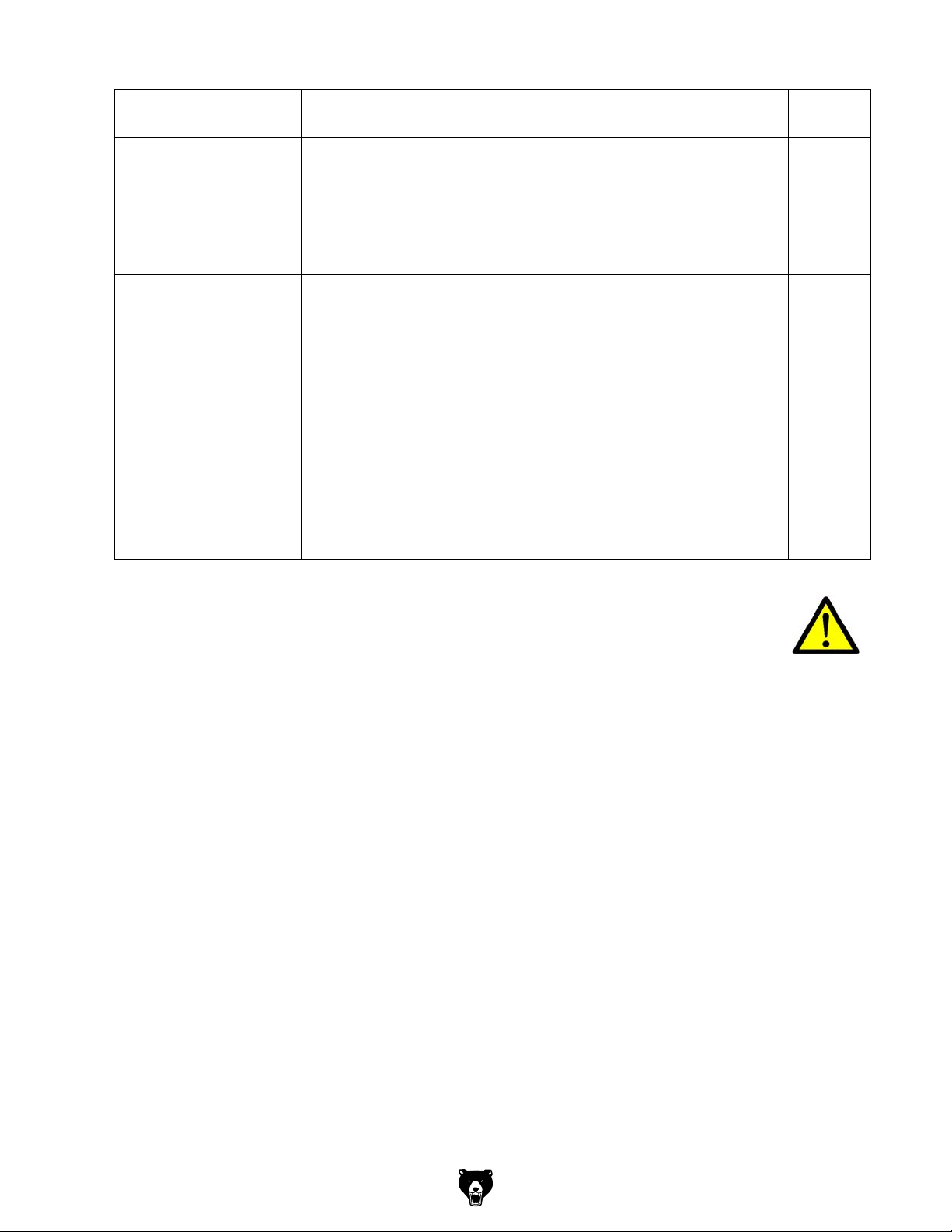
Interval Where? What? How?
Check
Check the tool
change function.
Positioning
Tool changer
Every six months
Cleaning
As required
Chip collection tray
Replacing the sight
window
60 months
Protective covers
By manual changing
Clean the chip collection tray of the cooling lubricant equipment.
"Cleaning and replacing of the polycarbonate
windows“ on page 81
11.3.1 Cleaning and replacing of the polycarbonate windows
WARNING!
The polycarbonate windows are part of the safety device on your CNC machine.
Damaged, scratched or even broken polycarbonate windows must be replaced
immediately.
A soft cloth should be used to clean the machine safety glass.
We recommend to replace the polycarbonate windows of the door after 60 months of commissioning of the CNC machine.
In the following cases, an immediate replacement is strongly recommended:
plastic deformation (distortion) by previous impact stress,
cracks,
Damage to the edge seal,
immersion of cooling agent in the composite structure,
destroyed or damaged window (coating) on the workspace or operator position.
Model G0877 (Mfd. Since 02/19)
-81-
Page 84
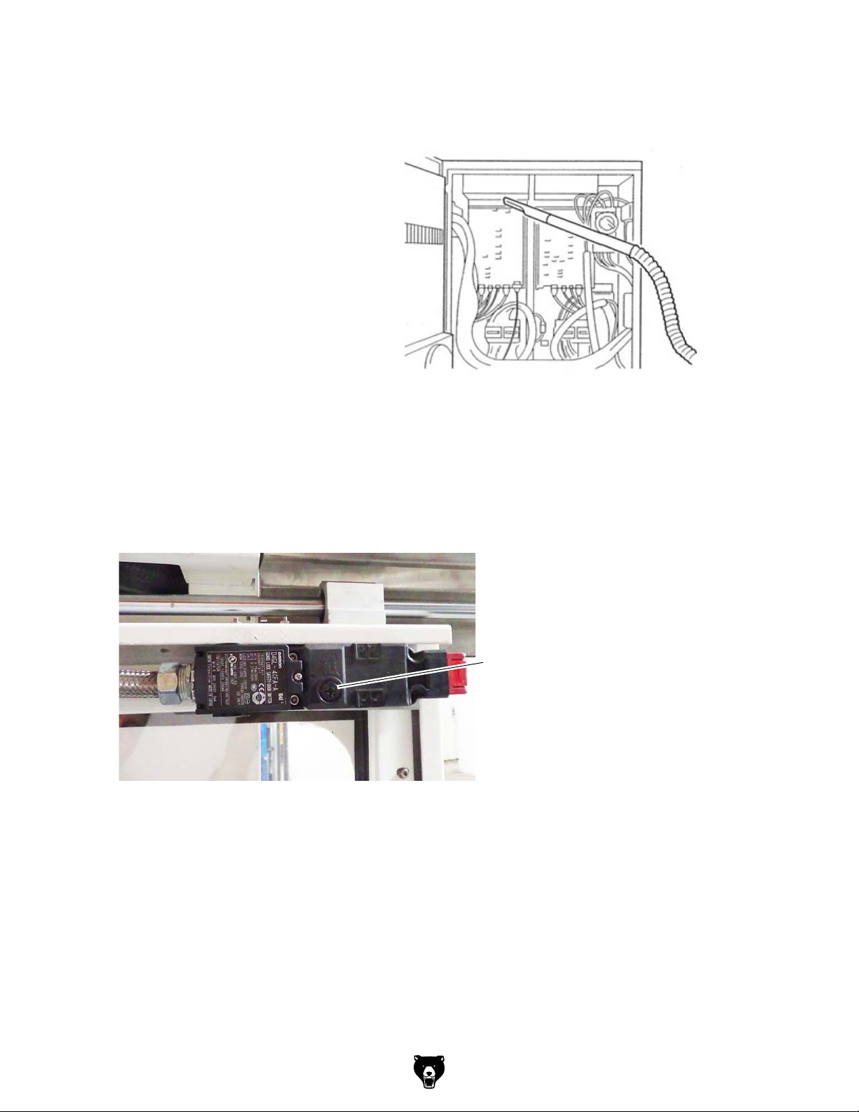
11.3.2 Cleaning electrical cabinet
Although the electrical cabinet is constructed to shut off external air, foreign particles such as dust and dirt may enter the
cabinet when the door is open.
Accumulation of foreign particles on the
printed circuit boards or other electronic
components could cause machine malfunction.
Clean the inside of the electrical cabinet
regularly.
Remove dust inside electrical cabinet with a
vacuum cleaner. Do not use compressed air
to clean inside the electrical cabinet.
Never touch printed circuit boards or parts
around the connector. Also avoid shock on
these parts.
It is recommended to clean the electrical cabinet every 1000 operating hours.
11.4 Interlock switch sliding door
The interlock switch can be mechanically unlock for repair and maintenance purposes. Perform
a safety check if you have set the interlock switch back to the ground state.
on page 17
"Safety check“
-82-
Unlocking
Img.11-2: Interlock switch sliding door
11.4.1 Drain compressed air service unit
The filtration of water and other impurities in the compressed air is automatic when compressed
air flows through the maintenance unit.
If the water level of the filter housing exceeds the maximum limit, the water enters the pneumatic equipment and cause damage.
Check the water level daily and drain the water level in the filter when needed.
Model G0877 (Mfd. Since 02/19)
Page 85
11.5 Cooling lubricants and tanks
CAUTION!
The cooling lubricant can cause diseases. Avoid direct contact with cooling lubricant or
parts covered in cooling lubricant.
Cooling lubricant circuits and tanks for water-cooling lubricant mixtures must be completely
emptied, cleaned and disinfected as needed, but at least once per year or every time the cooling lubricant is replaced.
If fine chips and other foreign matters are accumulated in the coolant tank, the machine can no
longer be correctly supplied with coolant. Furthermore, the lifetime of the coolant pump is
reduced.
When processing cast iron or similar materials generating fine chips, cleaning the coolant tank
more often is recommended.
Limit values
The cooling lubricant must be replaced, the cooling lubricant circuit and tank emptied,
cleaned and disinfected if
the pH value drops by more than 1 based on the value during initial filling. The maximum
permissible pH value during initial filing is 9.3
there is a perceivable change in the appearance, odour, floating oil or increase of the bacte-
ria to more than 10/6/ml
there is an increase in nitrite content to more than 20 ppm (mg/1) or nitrate content to more
than 50 ppm (mg/1)
there is an increase in the N-nitrosodiethanolamine (NDELA) to more than 5 ppm (mg/a)
CAUTION!
Comply with the manufacturer's specifications for mixture ratios, hazardous substances,
e.g. system cleaners, including their permissible minimum use times.
CAUTION!
Since the cooling lubricant escapes under high pressure, pumping out the coolant by
using the existing cooling lubricant pump via a pressure hose into a suitable tank is not
recommended.
ENVIRONMENTAL PROTECTION
During work on the cooling lubricant equipment please make sure that
collector tanks are used with sufficient capacity for the amount of liquid to be col-
lected.
liquids and oils should not be spilled on the ground.
Clean up any spilled liquid or oils immediately using proper oil-absorption methods and dispose of them in accordance with current statutory environmental regulations.
Collect leakages
Do not re-introduce liquids spilled outside the system during repair or as a result of leakage
from the reserve tank, instead collect them in a collecting container for disposal.
Disposal
Never dump oil or other substances which are harmful to the environment into water inlets, rivers or channels. Used oils must be delivered to a collection centre. Consult your supervisor if
you do not know where the collection centre is.
Model G0877 (Mfd. Since 02/19)
-83-
Page 86
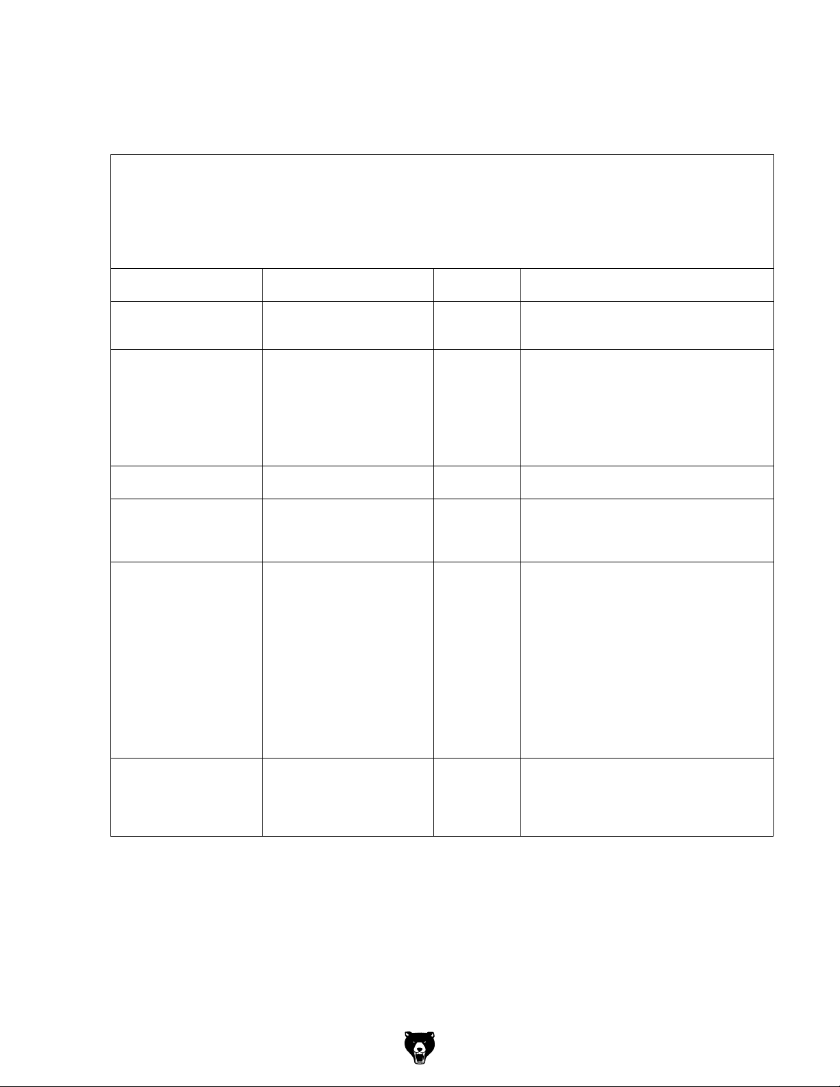
11.5.1 Inspection plan for water-mixed cooling lubricants
Company:
No.:
Date:
used cooling lubricant
size to be checked Inspection methods Inspection
intervals
noticeable
changes
pH value Laboratory techniques
Usage concentration Manual refractometer
Base reserve Acid titration in accordance
Nitrite content Test sticks method or labora-
Nitrate/nitrite content
of the preparation water, if
this is not removed from
the public
grid
Appearance, odour daily Find and rectify causes,
1)
electrometric with pH meter
Local measurement method:
with pH paper
(Special indicators with
suitable measuring range)
with
Manufacturer's recommendation
tory method
Test sticks method or laboratory method
weekly
1)
weekly
as required Method is independent of tramp oil content
1)
weekly
as required Use water from the public grid if there is
Procedure and comment
e.g. skim off oil, check filter, ventilate cooling
lubricant system
if pH value decreases
> 0.5 based on initial filing:
Measures in accordance manufacturer's recommendations
> 1.0 based on initial filing:
Replace cooling lubricant, clean cooling lubricant circulation system
Method results in incorrect values with tramp
oil content
> 20 mg/L nitrite:
Replace cooling lubricant or part
or inhibiting additives;
otherwise NDELA (N-nitrosodiethanolamine)
in the cooling lubricant system and in the air
must be determined
> 5 mg/L NDELA in the cooling lubricant system:
Replacement,
clean and disinfect cooling lubricant circulation system, find nitrite source and, if possible, rectify.
water from the pubic grid has
> 50 mg/l nitrate: Inform the waterworks
-84-
1)
The specified inspection intervals (frequency) are based on continuous operation. Other operational
conditions can result in other inspection intervals; exceptions are possible.
Editor:
Signature:
Model G0877 (Mfd. Since 02/19)
Page 87
11.5.2 Lubricants
Lubricant
Gear oil
Viscosity
ISO VG
VG 680
VG 460
VG 320
VG 220
VG 150
VG 100
VG 68
VG 46
VG 32
BP Energol
GR-XP 680
BP Energol
GR-XP 460
BP Energol
GR-XP 320
BP Energol
GR-XP 220
BP Energol
GR-XP 150
BP Energol
GR-XP 100
BP Energol
GR-XP 68
BP
Bartran 46NUTO H 46
SPARTAN
EP 680
SPARTAN
EP 460
SPARTAN
EP 320
SPARTAN
EP 220
SPARTAN
EP 150
SPARTAN
EP 100
SPARTAN
EP 68
(HLP 46)
BP Bartran 32NUTO H 32
(HLP 32)
Mobilgear
636
Mobilgear
634
Mobilgear
632
Mobilgear
630
Mobilgear
629
Mobilgear
627
Mobilgear
626
Mobil DTE
25
Mobil DTE
24
Shell Omala
680
Shell Omala
460
Shell Omala
320
Shell Omala
220
Shell Omala
150
Shell Omala
100
Shell Omala
68
Shell Tellus
S 46
Shell Tellus
S 32
Meropa 680
Meropa 460
Meropa 320
Meropa 220
Meropa 150
Meropa 100
Meropa 68
Anubia EP
46
Anubia EP
32
Gear grease
Special greases,
water resistant
Bearing grease
Energrease
BP
PR-EP 00
BP
Energrease
LS 3
FIBRAX EP
370 (Na-ver-
seift)
Mobilux EP
004
Mobilux EP 0
BEACON 3 Mobilux 3
Shell Alvania
GL 00 (Li-
verseift)
Shell Alvania
R 3 Alvania
G 3
Marfak 00
Multifak
Premium 3
Model G0877 (Mfd. Since 02/19)
-85-
Page 88
Basic Theory
The 808D machine control panel
(MCP) is used to select the
machine operating mode :
JOG - MDA - AUTO
Menu navigation
PPU
Function of
keyboard
MCP mode
Changing
Brief Instructions for 808D Milling
Preparation
Basic knowledge of programming for milling is requi red, before operating
of a machine !
The information provided in this brief insruction contains merely general descriptions or
characteristics of performance which in actual case of use do not always apply as
described or which may change as a result of further development of the products.
Preparation
Description
This unit describes the 808D PPU and MCP f unctionality, the coordinate system of a
milling machine and how to enter password s to access the system.
Content
PPU
PPU
Function of
Function of
keyboard
keyboard
User
User
interface
interface
-86-
MCP mode
MCP mode
Changing
Changing
MCP
MCP
Moving
Moving axis
axis
MCP
MCP
OEM
OEM
keys
Machine
Machine
coordinate
coordinate
system
system
Passwords
Passwords
End
Model G0877 (Mfd. Since 02/19)
Page 89
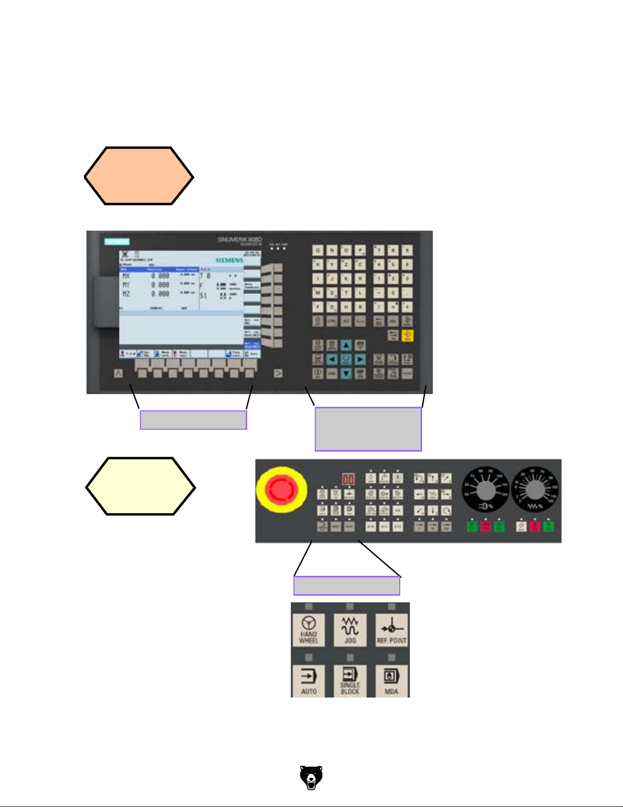
Preparation
Basic Theory
PPU
Function of
keyboard
The 808D panel
processing unit (PPU)
is used to input data
to the CNC and to
navigate to operating
areas of the system.
Menu navigation
MCP mode
Changing
The 808D machine control panel
(MCP) is used to select the
machine operating mode :
JOG - MDA - AUTO
Operating area
navigation
Mode navigation
Model G0877 (Mfd. Since 02/19)
-87-
Page 90

808D (PPU) has eight horizontal SKs on t he bottom of the screen. These SKs can
be activated with the corresponding button (located below).
User
interface
Meas.
tool
Meas.
work.
Set
REL
Preparation
MCP
Moving
axis
The 808D machine control panel (MCP)
is used to control manual operation of the
axis.
The machine can be moved with the
appropriate keys.
Axis movement
MCP
OEM
keys
The 808D machine control panel (MCP)
is used to control OEM machine
functions.
The machine functions can be activated
with the appropriate keys.
OEM keys
-88-
Model G0877 (Mfd. Since 02/19)
Page 91
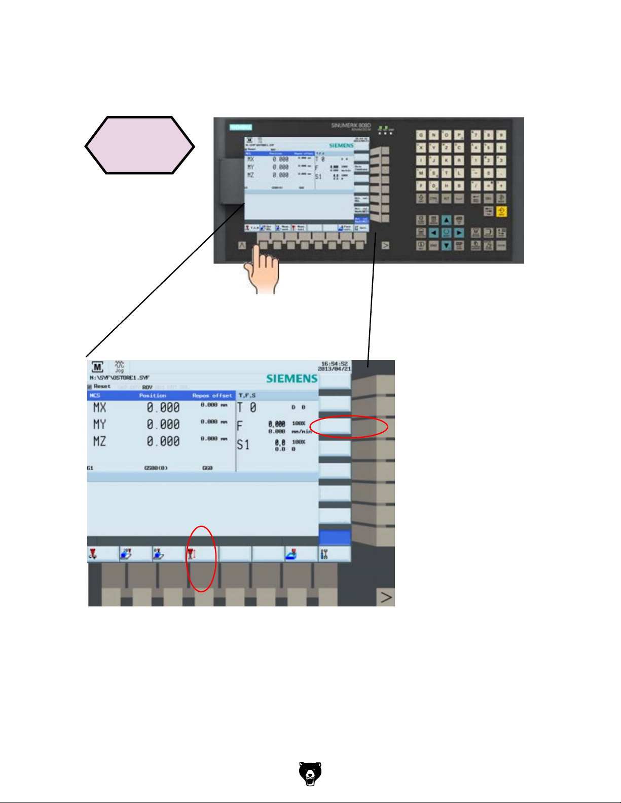
Preparation
User
interface
Axis
feedrate
808D (PPU) has eight
vertical softkeys (abbr.
SKs) on the right of the
screen. These SKs can
be activated with the
corresponding button
(located on the right).
Set
REL
Meas.
work.
Meas.
tool
808D (PPU) has eight horizontal SKs on t he bottom of the screen. These SKs can
be activated with the corresponding button (located below).
Model G0877 (Mfd. Since 02/19)
Face
cutt.
Act. val.
REL
Act. val.
Work(WCS)
Sett.T,S,M
-89-
Page 92

SEQUENCE
Step 1
Step 2
Changing
password
The service mode is opened with the
appropriate key combination.
In the service mode, the password
can be activated and deactivated.
End
Passwords
Set
password
Change
password
Delete
password
Preparation
Machine
coordinate
system
The Sinumerik 808D uses a
coordinate system which is
derived from the DIN 66217
standard.
The system is an international
standard and ensures
compatibility between machines
and coordinate programming.
The primary function of the
coordinate system is to ensure
that the tool length and tool
radius are calculated correctly in
the respective axis.
-90-
Model G0877 (Mfd. Since 02/19)
Page 93

Preparation
SEQUENCE
Passwords
Changing
password
Step 1
Passwords at the control are used to set the user’s right to
access the system. Tasks such as ”Basic Operating”,
“Advanced Operating” and commissioning functions all
depend on the passwords.
No password
Customer’s password
Manufacturer’s password
Machine operator
Advanced operator
OEM engineer
Customer’s password = CUSTOMER
Manufacturer’s password = SUNRISE
Usually the machine, operator does not need to change the
password.
The service mode is opened with the
appropriate key combination.
In the service mode, the password
can be activated and deactivated.
Step 2
Set
password
Change
password
Delete
password
Enter customer’s or manufacturer’s password
Change customer’s or manufacturer’s password
Delete customer’s or manufacturer’s password
End
Set
password
Change
+
password
Delete
password
Model G0877 (Mfd. Since 02/19)
-91-
Page 94
SEQUENCE
Please note the explicit switchin g on rules as specied by the
machine manufacturer.
Turn on the main switch of the machine.
Make sure you perform the following operation!
Step 1
Step 2
End
Switch on
the machine
PPU
Function of
keyboard
Switch on
the
machine
Release all the EMERGENCY STOP
buttons on the machine!
Switch on and referencing
Switch On and Referencing
Description
This unit describes how to switch the machine on and reference it.
Content
Switch on
Switch on
PPU
the
the machine
Function of
machine
keyboard
MCP mode
Reference
Changing
the
machine
End
-92-
Model G0877 (Mfd. Since 02/19)
Page 95

Switch on and referencing
SEQUENCE
Switch on
Switch on
PPU
the machine
the
Function of
machine
keyboard
Please note the explicit switchin g on rules as specied by the
machine manufacturer.
Step 1
Turn on the main switch of the machine.
Step 2
Make sure you perform the following operation!
Release all the EMERGENCY STOP
buttons on the machine!
End
Model G0877 (Mfd. Since 02/19)
-93-
Page 96
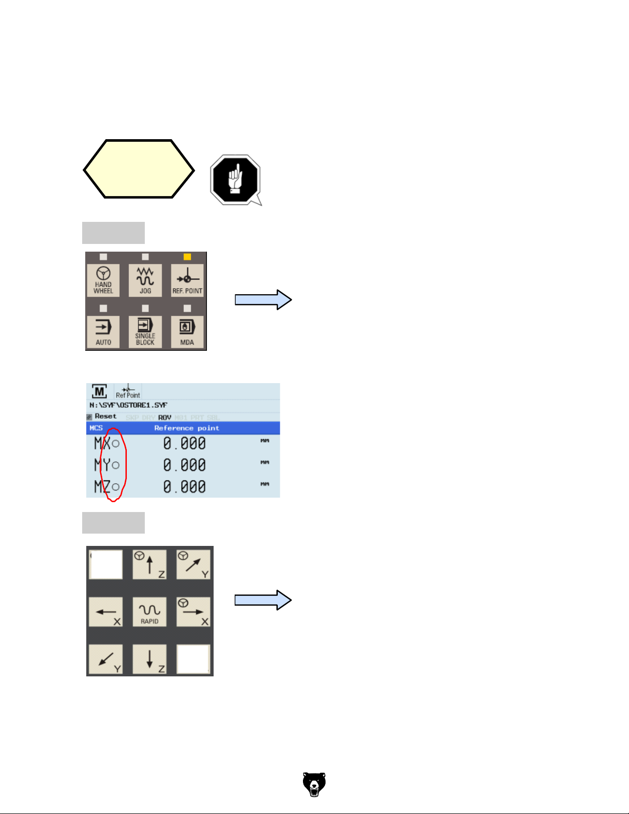
Step 3
End
Switch on and referencing
SEQUENCE
MCP mode
Reference
Changing
Step 1
the
machine
If your machine is cong ure with ABS encoder, you
do not nee d to reference the axis of the machine.
If your machine is tted with INC encoder, After
power on, the machine must rst be referenced!
After power on, the ma chine will be in the
reference point approach mode (default).
Step 2
If the axis is not referenced, the nonreferenced symbol (circle) is displayed
between the axis identier and the value.
The axes are referenced with the
corresponding axis traversing keys.
The traversing direction and keys are
specied by the machine manufacturer.
-94-
Model G0877 (Mfd. Since 02/19)
Page 97
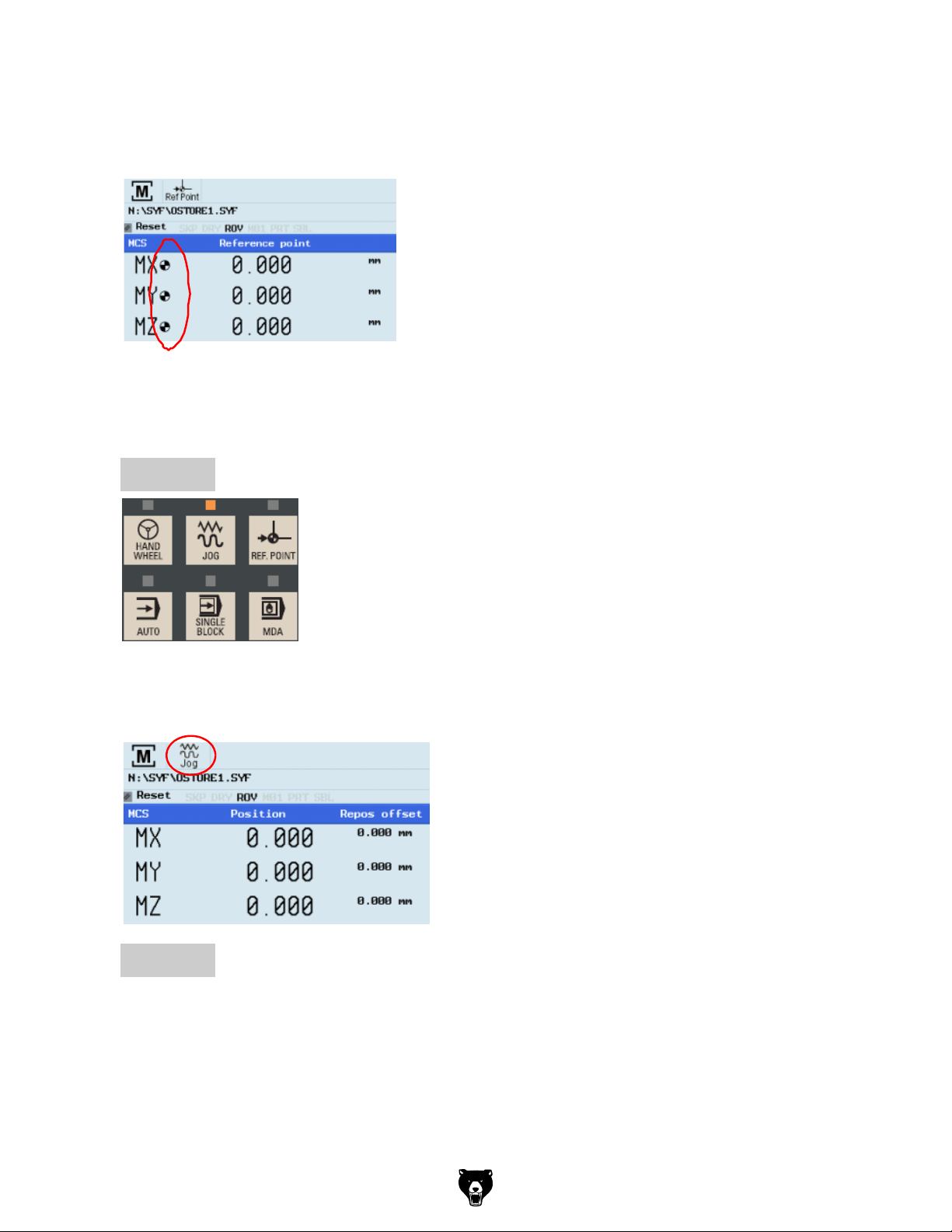
Switch on and referencing
After completing the referencing procedure for
all axes, the referenced symbol is displayed
next to the axis identier.
Step 3
After returning to JOG mode, use the axis
traversing keys to move the machine manually.
End
Model G0877 (Mfd. Since 02/19)
The machine can now be operated in JOG
mode.
During normal operation (JOG),the referenced
symbol is not shown on the screen.
-95-
Page 98

SEQUENCE
Please make sure the system is in JOG mode.
Press “Oset” on the PPU.
Press the “Tool list” SK on the PPU.
Step 1
Create
tool
Tool setup
Tool Setup
Description
This unit describes how to create and set up tools.
Content
Create
tool
Create tool
edge
Load tool into
active
position
Start
spindle
Measure
tool
Machine
JOG
coordinate
spindle
system
-96-
Move
machine with
handwheel
User
Execute M
interface
function
End
Model G0877 (Mfd. Since 02/19)
Page 99
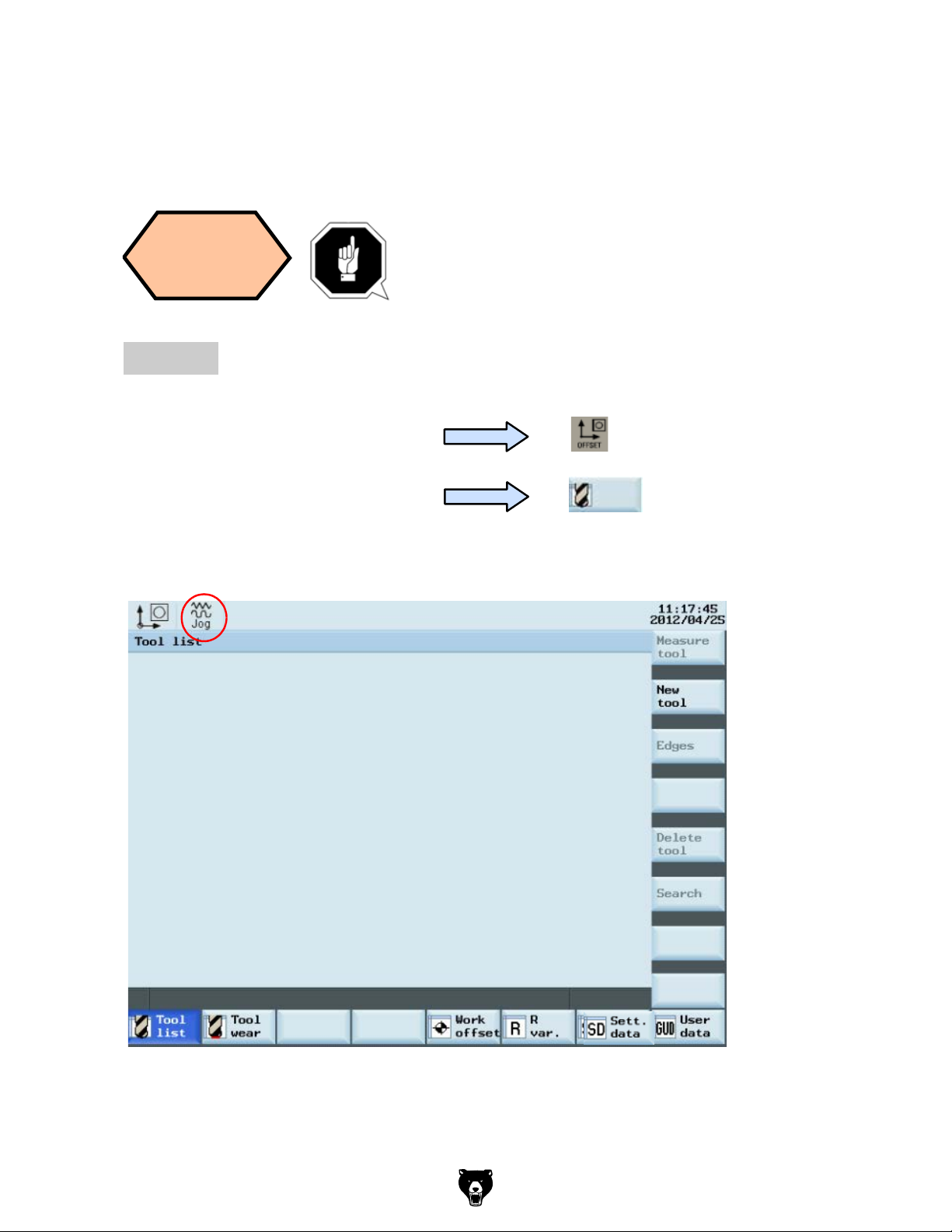
Tool setup
SEQUENCE
Create
tool
A tool must have been created and measured
before executing the program.
Step 1
Please make sure the system is in JOG mode.
Press “Oset” on the PPU.
Press the “Tool list” SK on the PPU.
Tool
list
Model G0877 (Mfd. Since 02/19)
-97-
Page 100
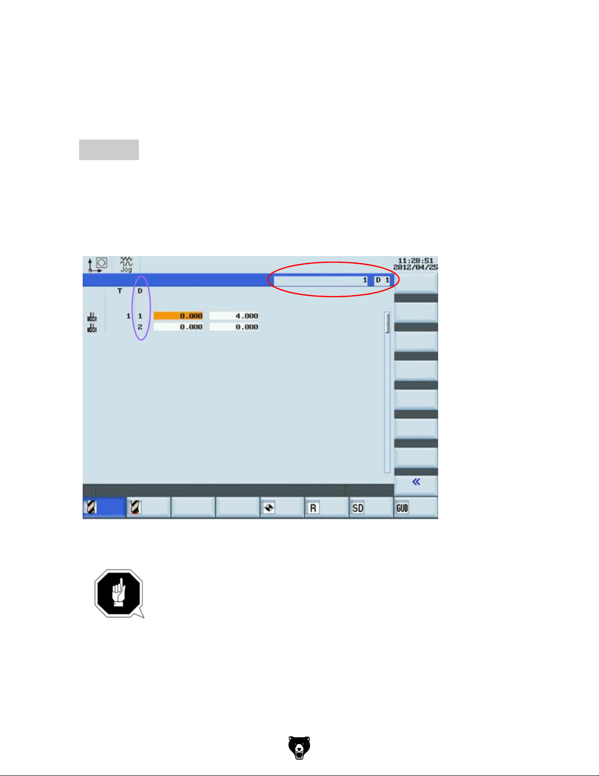
Load tool into
Spindle
Press the “Machine” key on the PPU
Press “CYCLE START” on the MCP
Press the “JOG” key on the MCP
Press the “T.S.M” SK on the PPU
T,S,M
Tool change
Spindle speed
Spindle direction
Activate zerooset
Other M function
Meas.
work.
Set
rel
Press ´CYCLE START´
Tool setup
SEQUENCE
Step 2
A new tool edge can be added in this way and dierent lengths and radii can be
entered as required.
The red circle shows the actual active tool and tool edge,the purple circle shows how
many tool edges have been created and the related data for each tool edge.
Tool list
Type
Tool
list
Lenght1
Tool
wear
Geometry
Radius
Active tool no
Work
oset
R
var.
Sett.
data
New
edge
Reset
edge
Delete
edge
Back
User
data
-98-
A maximum of nine tool edges can be created for each tool!
Dierent tool lengths and radii can be saved in dierent tool edges as
required.
Please select the right tool edge for machining according to
requirement!
Model G0877 (Mfd. Since 02/19)
 Loading...