

Page 1
MODEL G0876
8" X 27" ENCLOSED CNC MILL
w/AUTO TOOL CHANGER
OWNER'S MANUAL
(For models manufactured since 12/22)
***Keep for Future Reference***
V2.02.23
Page 2

This manual provides critical safety instructions on the proper setup,
operation, maintenance, and service of this machine/tool. Save this
document, refer to it often, and use it to instruct other operators.
Failure to read, understand and follow the instructions in this manual
may result in fire or serious personal injury—including amputation,
electrocution, or death.
The owner of this machine/tool is solely responsible for its safe use.
This responsibility includes but is not limited to proper installation in
a safe environment, personnel training and usage authorization,
proper inspection and maintenance, manual availability and comprehension, application of safety devices, cutting/sanding/grinding tool
integrity, and the usage of personal protective equipment.
The manufacturer will not be held liable for injury or property damage
from negligence, improper training, machine modifications or misuse.
Some dust created by power sanding, sawing, grinding, drilling, and
other construction activities contains chemicals known to the State
of California to cause cancer, birth defects or other reproductive
harm. Some examples of these chemicals are:
• Lead from lead-based paints.
• Crystalline silica from bricks, cement and other masonry products.
• Arsenic and chromium from chemically-treated lumber.
Your risk from these exposures varies, depending on how often you
do this type of work. To reduce your exposure to these chemicals:
Work in a well ventilated area, and work with approved safety equipment, such as those dust masks that are specially designed to filter
out microscopic particles.
Page 3

Table of Contents
11
10
0.1 Machine data sheet ........................................ 3
1 Safety
1.1 Safety instructions for machinery ................... 6
1.2 Additional safety for CNC mills/lathes ............ 8
1.3 Safety instructions (warning notes) ................. 9
1.4 Intended use ............
1.5 Reasonably foreseeable misuse
1.6 Possible dangers w/CNC machines ............... 12
1.7 Qualification of personnel ............................... 12
1.8 User positions ................................................ 14
1.9 Safety devices ............................................... 14
1.10 Safety check .................................................. 17
1.11 Personal protective equipment
1.12
Safety during operation
1.13
Safety during maintenance
1.14
Disconnecting/securing CNC machine
1.15 Unattended operation ...................................... 20
1.16 Accident report ............................................... 20
1.17 Electrical system ............................................. 20
1.18 Inspection deadlines .............................. 21
1.19 Clamping devices ................................. 21
1.20
Tools and tool holding fixtures .................. 21
....................................... 10
..................... 11
..................... 18
................................... 18
............................ 19
.......... 19
2 Power supply
2.1 Availability ...................................................... 22
2.2 Full-load current rating ................................... 22
2.3 Circuit information .......................................... 22
2.4 Circuit requirements for 220V ........................ 22
2.5 Connection type ............................................. 22
2.6 Grounding instructions ................................... 23
2.7 Extension cords .............................................. 23
3 Assembly and commissioning
3.1 Scope of delivery ............................................ 24
3.2 Transport ........................................................ 24
3.3 Installation and assembly ............................... 25
3.4 First commissioning ....................................... 31
3.5 Refill central lubrication system ...................... 33
3.6 Functional test and controls ............................ 35
4 General information about CNC
4.1 Compensation of geometry
4.2 Coordinate systems on CNC machines .......... 36
4.3 NC mathmatics .............................................. 38
Trigonometric functions ................................. 39
4.4
............................. 36
User interface, machine control panel
5
5.1
Screen arrangement ................................... 40
5.2
Elements on the front panel
5.3
Controls on the control panel ...................... 46
5.4
Protection levels .......................................... 51
6
Operation
6.1 Safety .......................................................... 53
6.2
Control and indicating elements
6.3
Operational modes
6.4 Programming ............
6.5 Operation of the machine
6.6
Operational modes
6.7
Programming
6.8
Starting the program
6.9
Central lubrication system
6.10
Data interfaces and current collection
6.11
Selecting the speed .................................. 62
7
Brief instruction for 808D milling
7.1
Preparation
7.2
Switch on and referencing
Tool Setup
7.3
Workpiece setup
7.4
7.5
Create part program: part 1
7.6
Create part program: part 2
Simulate program
7.7
Test program
7.8
7.9
Machine pieces
7.10
Program restart
Additional information: part 1
7.11
Additional information: part 2
7.12
7.13
Sample program
7.14
ISO mode
7.15
Appendix
8
M - code list, M functions
8.1
M-function for milling machines
8.2
G functions to PAL
9
Notes, messages, and errors
Sinumerik 808D
.................................................. 75
.................................................... 212
.................................................... 230
.................................................... 242
...................................... 54
..................................... 61
.............................................. 61
.................................... 61
................................................. 65
......................................... 91
....................................... 142
.............................................. 146
.......................................... 150
........................................... 156
......................................... 198
...................................... 238
......................... 41
................. 53
.................................... 54
............................ 55
.......................... 62
.......................... 71
........................ 100
........................ 116
..................... 160
...................... 180
.................. 236
........................... 239
Maintenance
11.1
Operating material
11.2
Safety
.......................................................... 244
Inspection and maintenance
11.3
Sliding door interlock switch
11.4
Cooling lubricants and tanks
11.5
...................................... 243
....................... 246
........................ 249
....................... 251
........ 62
Page 4

12
Wiring Diagrams
Wiring safety instructions
12.1
System wiring diagrams (1-2)
12.2
12.3
System wiring diagrams (3-4)
12.4
System wiring diagrams (5-6)
Handwheel wiring diagram
12.4
X/Y/Z motors wiring diagram
12.5
13
Parts
13.1
Housing
13.2
Base
Milling head
13.3
Milling table
13.4
13.5
X-Axis
13.6
Y-Axis
Z-Axis
13.7
Column
13.8
Auto tool changer
13.9
Electrical cabinet
13.10
Pneumatic system
13.11
Labels & cosmetics
13.12
14
Warranty & returns
Table of Contents (Cont.)
............................ 253
..................... 254
..................... 255
..................... 256
......................... 252
...................... 252
....................................................... 258
........................................................... 260
................................................ 261
................................................. 262
.......................................................... 263
........................................................ 264
........................................................ 265
........................................................ 266
......................................... 268
......................................... 269
....................................... 270
..................................... 271
.............................................. 272
Page 5

Customer Service #: (570) 546-9663 · To Order Call: (800) 523-4777 · Fax #: (800) 438-5901
MODEL G0876 8" X 27" ATC ENCLOSED CNC MILL
Product Dimensions:
Weight ......................................................................................................................................................................... 3080 lbs.
Width (side-to-side) x Depth (front-to-back) x Height .......................................................................................71 x 65 x 79 in.
Footprint (Length/Width) ..........................................................................................................................................110 x 86 in.
Shipping Dimensions:
Type ........................................................................................................................................................................ Wood Crate
Content .......................................................................................................................................................................... Machine
Weight .......................................................................................................................................................................... 3350 lbs.
Length x Width x Height ...............................................................................................................................80 x 72-1/2 x 85 in.
Must Ship Upright .................................................................................................................................................................Yes
Electrical:
Power Requirement ................................................................................................................................ 220V, 3-Phase, 60 Hz
Full-Load Current Rating ................................................................................................................................................... 14.1A
Minimum Circuit Size ........................................................................................................................................................... 20A
Connection Type ..................................................................................................................................................... Cord & Plug
Power Cord Length ........................................................................................................................................................ 6-1/2 ft.
Power Cord Gauge .......................................................................................................................................................12 AWG
Recommended Plug Type .................................................................................................................................................15-20
Motors:
Spindle
Horsepower ...............................................................................................................................................................3 HP
Phase .................................................................................................................................................................. 3-Phase
Amps ......................................................................................................................................................................... 6.4A
Speed ............................................................................................................................................................10,000 RPM
Type ......................................................................................................................................................................... Servo
Power Transfer .................................................................................................................................................. Belt Drive
Bearings ...................................................................................................................Shielded & Permanently Lubricated
X-Axis
Horsepower ...............................................................................................................................................................1 HP
Phase .................................................................................................................................................................. 3-Phase
Amps ......................................................................................................................................................................... 2.1A
Speed ..............................................................................................................................................................4,000 RPM
Type ......................................................................................................................................................................... Servo
Power Transfer ............................................................................................................................................... Direct Drive
Bearings ......................................................................................................................Sealed & Permanently Lubricated
Y-Axis
Horsepower ...............................................................................................................................................................1 HP
Phase .................................................................................................................................................................. 3-Phase
Amps ......................................................................................................................................................................... 2.1A
Speed ..............................................................................................................................................................4,000 RPM
Type ......................................................................................................................................................................... Servo
Power Transfer ............................................................................................................................................... Direct Drive
Bearings ......................................................................................................................Sealed & Permanently Lubricated
Model G0876 (Mfd. Since 12/22)
-3-
Page 6

Z-Axis
± 0.0008 in. (0.020 mm)
± 0.0005 in. (0.013 mm)
Horsepower ............................................................................................................................................................1.3 HP
Phase .................................................................................................................................................................. 3-Phase
Amps ............................................................................................................................................................................ 3A
Speed ..............................................................................................................................................................3,000 RPM
Type ......................................................................................................................................................................... Servo
Power Transfer ............................................................................................................................................... Direct Drive
Bearings ......................................................................................................................Sealed & Permanently Lubricated
Tool Changer
Horsepower ........................................................................................................................................................ 60 Watts
Phase .................................................................................................................................................................. 3-Phase
Amps ....................................................................................................................................................................... 0.24A
Speed ...............................................................................................................................................................1360 RPM
Type ......................................................................................................................................................................... Servo
Power Transfer .................................................................................................................................................... Gearbox
Bearings ......................................................................................................................Sealed & Permanently Lubricated
Coolant Pump
Horsepower ........................................................................................................................................................ 97 Watts
Phase .................................................................................................................................................................. 3-Phase
Amps ......................................................................................................................................................................... 0.5A
Speed ...............................................................................................................................................................2800 RPM
Type .................................................................................................................................................................... Induction
Power Transfer ............................................................................................................................................... Direct Drive
Bearings ...................................................................................................................Shielded & Permanently Lubricated
Main Specifications:
Operation Information
Max Distance Spindle to Column ............................................................................................................................. 11 in.
Max Distance Spindle to Table ..........................................................................................................................16-1/2 in.
Longitudinal Table Travel (X-Axis) ...................................................................................................................12-3/16 in.
Cross Table Travel (Y-Axis) .................................................................................................................................7-3/4 in.
Vertical Head Travel (Z-Axis) .............................................................................................................................11-3/4 in.
Position Resolution .....................................................................................................................
Repeat Position Resolution ........................................................................................................
Tool Changer Info
Type .......................................................................................................................................................... Turntable Style
Capacity .................................................................................................................................................................8 Tools
Maximum Tool Weight ............................................................................................................................................. 13 lbs
Maximum Tool Diameter with Adjacent Tool .......................................................................................................2-3/4 in.
Tool Change Average Time .............................................................................................................................6 Seconds
Table Info
Table Length ............................................................................................................................................................27 in.
Table Width ..........................................................................................................................................................8-1/4 in.
Table Thickness ...................................................................................................................................................2-3/8 in.
Table Height (from Floor/Base) ................................................................................................................................45 in.
Table Weight Capacity .........................................................................................................................................220 lbs.
Number of T-Slots ...........................................................................................................................................................3
T-Slot Size ............................................................................................................................................................... 5/8 in.
T-Slots Centers ....................................................................................................................................................2-1/2 in.
X-Axis Rapid Feed Rate ...................................................................................................................................... 400 IPM
Y-Axis Rapid Feed Rate ...................................................................................................................................... 400 IPM
Z-Axis Rapid Feed Rate ...................................................................................................................................... 400 IPM
-4-
Model G0876 (Mfd. Since 12/22)
Page 7

Spindle Info
BT30 x 45°
50 - 10,000 RPM
13 Gallons
Spindle Taper ........................................................................................................................................................... BT30
Pull Stud ..........................................................................................................................................................
Spindle Speed Range ...........................................................................................................................
Spindle Bearings (Size & Type) ...............................................................................................Angular Contact Bearings
Fluid Capacities
Coolant Capacity .............................................................................................................................................
Construction
Spindle Housing/Quill ................................................................................................................................................Steel
Table ................................................................................................................................................................... Cast Iron
Head ................................................................................................................................................................... Cast Iron
Column/Base ...................................................................................................................................................... Cast Iron
Stand ..................................................................................................................................................................Cast Iron
Paint Type/Finish ...................................................................................................................................................Enamel
Other Specifications:
Country of Origin ............................................................................................................................................................... China
Warranty ........................................................................................................................................................................... 1 Year
Approximate Assembly & Setup Time .....................................................................................................................1-1/2 Hours
Serial Number Location ..................................................................................................................................Machine ID Label
ISO 9001 Factory ..................................................................................................................................................................Yes
Features:
Siemens Sinumerk® CNC Controller
Servo Motors with Ball Screws on All Axes
Built-In Pendant/Hand Controller
Powerful 3 HP Spindle Motor
50–10,000 RPM Spindle Speeds
Easy Access to Table from 3 Sides
Hands-Free Tool Changes with 8-Position Automatic Tool Changer (ATC)
Rapid Table Speeds of Up to 400 in./min.
Heavy-Duty BT30 Spindle
Model G0876 (Mfd. Since 12/22)
-5-
Page 8
SAFETY
For Your Own Safety, Read Instruction
Manual Before Operating This Machine
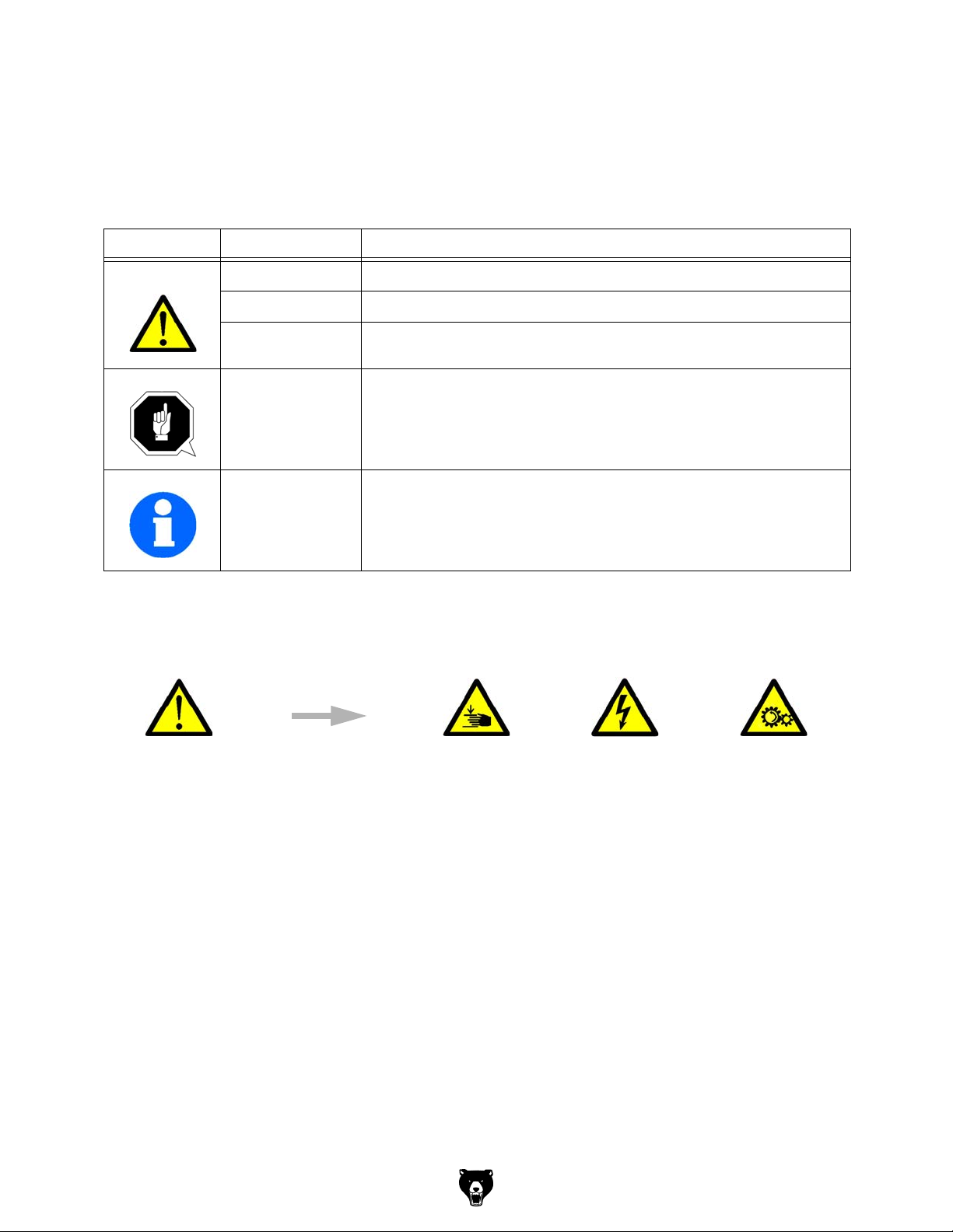
The purpose of safety symbols is to attract your attention to possible hazardous conditions.
This manual uses a series of symbols and signal words intended to convey the level of importance of the safety messages. The progression of symbols is described below. Remember that
safety messages by themselves do not eliminate danger and are not a substitute for proper
accident prevention measures. Always use common sense and good judgment.
Indicates an imminently hazardous situation which, if not avoided,
WILL result in death or serious injury.
Indicates a potentially hazardous situation which, if not avoided,
COULD result in death or serious injury.
Indicates a potentially hazardous situation which, if not avoided,
MAY result in minor or moderate injury. It may also be used to alert
against unsafe practices.
Alerts the user to useful information about proper operation of the
NOTICE
machine to avoid machine damage.
Safety Instructions for Machinery
OWNER’S MANUAL. Read and understand this
owner’s manual BEFORE using machine.
TRAINED OPERATORS ONLY. Untrained operators have a higher risk of being hurt or killed.
Only allow trained/supervised people to use this
machine. When machine is not being used, disconnect power, remove switch keys, or lock-out
machine to prevent unauthorized use—especially
around children. Make your workshop kid proof!
DANGEROUS ENVIRONMENTS. Do not use
machinery in areas that are wet, cluttered, or have
poor lighting. Operating machinery in these areas
greatly increases the risk of accidents and injury.
MENTAL ALERTNESS REQUIRED. Full mental
alertness is required for safe operation of machinery. Never operate under the influence of drugs or
alcohol, when tired, or when distracted.
ELECTRICAL EQUIPMENT INJURY RISKS.
You can be shocked, burned, or killed by touching
live electrical components or improperly grounded
machinery. To reduce this risk, only allow qualified
service personnel to do electrical installation or
repair work, and always disconnect power before
accessing or exposing electrical equipment.
DISCONNECT POWER FIRST.
nect machine from power supply BEFORE making adjustments, changing tooling, or servicing
machine. This prevents an injury risk from unintended startup or contact with live electrical components.
EYE PROTECTION. Always wear ANSI-approved
safety glasses or a face shield when operating or
observing machinery to reduce the risk of eye
injury or blindness from flying particles. Everyday
eyeglasses are NOT approved safety glasses.
Always discon-
-6-
Model G0876 (Mfd. Since 12/22)
Page 9

WEARING PROPER APPAREL. Do not wear
clothing, apparel or jewelry that can become
entangled in moving parts. Always tie back or
cover long hair. Wear non-slip footwear to reduce
risk of slipping and losing control or accidentally
contacting cutting tool or moving parts.
HAZARDOUS DUST. Dust created by machinery
operations may cause cancer, birth defects, or
long-term respiratory damage. Be aware of dust
hazards associated with each workpiece material. Always wear a NIOSH-approved respirator to
reduce your risk.
HEARING PROTECTION. Always wear hearing protection when operating or observing loud
machinery. Extended exposure to this noise
without hearing protection can cause permanent
hearing loss.
REMOVE ADJUSTING TOOLS. Tools left on
machinery can become dangerous projectiles
upon startup. Never leave chuck keys, wrenches,
or any other tools on machine. Always verify
removal before starting!
USE CORRECT TOOL FOR THE JOB. Only use
this tool for its intended purpose—do not force
it or an attachment to do a job for which it was
not designed. Never make unapproved modifications—modifying tool or using it differently than
intended may result in malfunction or mechanical
failure that can lead to personal injury or death!
AWKWARD POSITIONS. Keep proper footing
and balance at all times when operating machine.
Do not overreach! Avoid awkward hand positions
that make workpiece control difficult or increase
the risk of accidental injury.
CHILDREN & BYSTANDERS. Keep children and
bystanders at a safe distance from the work area.
Stop using machine if they become a distraction.
GUARDS & COVERS. Guards and covers reduce
accidental contact with moving parts or flying
debris. Make sure they are properly installed,
undamaged, and working correctly BEFORE
operating machine.
FORCING MACHINERY. Do not force machine.
It will do the job safer and better at the rate for
which it was designed.
NEVER STAND ON MACHINE. Serious injury
may occur if machine is tipped or if the cutting
tool is unintentionally contacted.
STABLE MACHINE. Unexpected movement during operation greatly increases risk of injury or
loss of control. Before starting, verify machine is
stable and mobile base (if used) is locked.
USE RECOMMENDED ACCESSORIES. Consult
this owner’s manual or the manufacturer for recommended accessories. Using improper accessories will increase the risk of serious injury.
UNATTENDED OPERATION. To reduce the
risk of accidental injury, turn machine OFF and
ensure all moving parts completely stop before
walking away. Never leave machine running
while unattended.
MAINTAIN WITH CARE. Follow all maintenance
instructions and lubrication schedules to keep
machine in good working condition. A machine
that is improperly maintained could malfunction,
leading to serious personal injury or death.
DAMAGED PARTS. Regularly inspect machine
for damaged, loose, or mis-adjusted parts—or
any condition that could affect safe operation.
Immediately repair/replace BEFORE operating
machine. For your own safety, DO NOT operate
machine with damaged parts!
MAINTAIN POWER CORDS. When disconnecting cord-connected machines from power, grab
and pull the plug—NOT the cord. Pulling the cord
may damage the wires inside. Do not handle
cord/plug with wet hands. Avoid cord damage by
keeping it away from heated surfaces, high traffic
areas, harsh chemicals, and wet/damp locations.
EXPERIENCING DIFFICULTIES. If at any time
you experience difficulties performing the intended operation, stop using the machine! Contact our
Technical Support at (570) 546-9663.
Model G0876 (Mfd. Since 12/22)
-7-
Page 10

Additional Safety for CNC Mills/Lathes
You can be seriously injured or killed by getting clothing, jewelry, or long hair entangled with
rotating cutter/spindle. You can be severely cut or have fingers amputated from contact with
rotating cutters. You can be blinded or struck by broken cutting tools, metal chips, workpieces,
or adjustment tools thrown from the rotating spindle with great force. To reduce your risk of
serious injury when operating this machine, completely heed and understand the following:
UNDERSTAND ALL CONTROLS. Make sure
you understand the function and proper use of all
controls before starting. This will help you avoid
making mistakes that result in serious injury.
AVOIDING ENTANGLEMENT. DO NOT wear
loose clothing, gloves, or jewelry, and tie back
long hair. Keep all guards in place and secure.
Always allow spindle to stop on its own. DO NOT
stop spindle using your hand or any other object.
EYE INJURIES. Operator and bystanders MUST
wear ANSI-approved safety glasses to help protect eyes from thrown metal shards and chips.
USE CORRECT SPINDLE SPEED. Follow recommended speeds and feeds for each size and
type of cutting tool. This helps avoid tool breakage
during operation and ensures best cutting results.
INSPECT CUTTING TOOL. Inspect cutting tools
for sharpness, chips, or cracks before each use.
Replace dull, chipped, or cracked cutting tools
immediately.
UNATTENDED MACHINE. Operator MUST be
present to immediately stop machine in case of
malfunction to prevent injury to bystanders and
machine damage.
POWER DISRUPTION. In event of power outage
during operation, turn spindle switch OFF to avoid
a possible sudden startup once power is restored.
SECURE WORKPIECE TO TABLE. Clamp workpiece to table or secure in a vise mounted to table,
so workpiece cannot unexpectedly shift or spin
during operation. NEVER hold workpiece by hand
during operation.
DISCONNECT POWER FIRST. To reduce risk of
electrocution or injury from unexpected startup,
make sure mill/drill is turned OFF, disconnected
from power, and all moving parts have come to
a complete stop before changing cutting tools or
starting any inspection, adjustment, or maintenance procedure.
CLEAN MACHINE SAFELY. Metal chips or shavings can be razor sharp. DO NOT clear chips
by hand or compressed air that can force chips
farther into machine—use a brush or vacuum
instead. Never clear chips while spindle is turning.
PROPERLY MAINTAIN MACHINE. Keep
machine in proper working condition to help
ensure that it functions safely and all guards and
other components work as intended. Perform routine inspections and all necessary maintenance.
Never operate machine with damaged or worn
parts that can break or result in unexpected movement during operation.
SAFE OPERATING LOCATION. DO NOT place
machine where it can be exposed to rain or moisture. Exposure to water creates a shock hazard
and will reduce life of machine.
-8-
Model G0876 (Mfd. Since 12/22)
Page 11
1.3 Safety instructions (warning notes)
1.3.1 Classification of hazards
We classify the safety warnings into different categories. The table below gives an overview of
the classification of symbols (ideogram) and the warning signs for each specific danger and its
(possible) consequences.
Symbol Warning alert Definition / consequence
DANGER!
WARNING!
CAUTION!
ATTENTION!
In case of specific dangers, we replace the pictogram with
INFORMATION
Impending danger that will cause serious injury or death to people.
A danger that can cause serious injury or death.
A danger or unsafe procedure that can cause personal injury or damage to
property.
Situation that could cause damage to the CNC-machine and products and
other types of damage.
No risk of injury to people.
Practical tips and other important or useful information and notes.
No dangerous or harmful consequences for people or objects.
general danger by a
warning of
Model G0876 (Mfd. Since 12/22)
injury to hands, hazardous electrical
voltage,
rotating
parts.
-9-
Page 12

1.3.2 Other pictograms
Activation forbidden! Do not step into the
machine!
Wear protective boots! Use ear protection! Wear protective glasses! Read the operating instruc-
Warning: suspended loads! Warning of oxidizing sub-
stances!
Protect the environment! Contact address
Do not extinguish with
water!
Caution, danger of explo-
sive substances!
Access forbidden!
tion before commissioning!
Warning: danger of slip-
ping!
1.4 Intended use
WARNING!
In the event of improper use of the CNC machine
will endanger personnel,
the CNC machine and other material property of the operating company will be
endangered,
the correct function of the CNC machine may be affected.
The CNC machine is designed and manufactured to be used for milling and drilling cold metals
or other non-flammable materials or materials that do not constitute a health hazard by using
commercial milling and drilling tools.
Using this machine it is possible to perform dry processing as well as processing by using cool-
ing lubricants.
The limit values of the balances of the tools need to be observed.
fixtures“ on page 21
The CNC machine must only be installed and operated in a dry and well-ventilated place.
The CNC machine is designed and manufactured to be used in a non-explosive environment.
If the CNC machine is used in any way other than described above or modified without the
approval of Grizzly Industrial, Inc., then the CNC machine is being used improperly.
We will not be held liable for any damages resulting from any operation which is not in accordance with the intended use.
"Cooling lubricants“ on page 243
"Tools and tool holding
express
-10 -
Model G0876 (Mfd. Since 12/22)
Page 13

We expressly point out that the guarantee or CE conformity will expire, if any constructive, tech-
nicolor procedural changes are not performed by Grizzly Industrial, Inc.
It is also part of intended use that you
the limits of performance of the CNC machine are observed,
the operating manual is observed,
the inspection and maintenance instructions are observed.
WARNING!
Severe injuries due to non-intended use.
It is forbidden to make any modifications or alternations to the operation values of the
CNC machine. They could endanger the personnel and cause damage to the CNC
machine.
1.5 Reasonably foreseeable misuse
Any other use other than that specified under "Intended use" or any use beyond the described
use shall be deemed as non-intended use and is not permissible.
Any other use has to be discussed with the manufacturer.
It is only allowed to process metal, cold and non-inflammable materials with the milling
machine.
In order to avoid misuse, it is necessary to read and understand the operating instructions
before first commissioning.
Operators must be qualified.
1.5.1 Avoiding misuse
Use of suitable cutting tools.
Adapting the speed adjustment and feed to the material and workpiece.
Clamp workpieces firmly and vibration-free.
ATTENTION!
The workpiece is always to be fixed by a machine vice, jaw chuck or by another
appropriate clamping tool such as for the clamping claws.
WARNING!
Risk of injury caused by flying workpieces.
Clamp the workpiece in the machine vice. Make sure that the workpiece is firmly clamped in the
machine vice and that the machine vice is firmly clamped onto the machine table.
Use cooling and lubricating agents to increase the durability of the tool and to improve the
surface quality.
Clamp the cutting tools and workpieces on clean clamping surfaces.
Sufficiently lubricate the machine.
Correctly adjust the bearing clearance and the guidings.
ATTENTION!
Do not use the drill chuck as a milling tool. Never clamp a milling cutter into a drill
chuck. Use a collet chuck with collets for the end mill.
Model G0876 (Mfd. Since 12/22)
-11-
Page 14

1.6 Possible dangers caused by the CNC machine
The CNC machine has been tested for operational safety. The construction and type are state
of the art.
Nevertheless, there is a residual risk as the CNC machine operates with
rotating parts,
electrical voltage and currents,
compressed air,
rapid moves.
We have used construction resources and safety techniques to minimize the health risk to personnel resulting from these hazards.
If the CNC machine is used and maintained by personnel who are not duly qualified, there may
be a risk resulting from incorrect or unsuitable maintenance of the lathe.
INFORMATION
Everyone involved in the assembly, commissioning, operation and maintenance must
be duly qualified,
and strictly follow these operating instructions.
In the event of improper use
there may be a risk to personnel,
there may be a risk of damage to the CNC machine and other material values,
the correct function of the CNC machine may be affected.
Always switch off the CNC machine and disconnect it from the mains, when cleaning or maintenance work is carried out.
WARNING!
The CNC machine may only be operated with functional safety devices. Disconnect the
CNC machine immediately, whenever you detect a failure in the safety devices or when
they are not fitted!
All additional parts of the machine which had been added by the customer need to be
equipped with the prescribed safety devices.
This is your responsibility being the operating company!
1.7 Qualification of personnel
1.7.1 Target group
This manual is addressed to
the operating companies,
operators having sufficient specialist knowledge,
the maintenance personnel.
Therefore, the warning notes refer to both, operation and maintenance personnel of the CNC
machine.
Determine clearly and explicitly who will be responsible for the different activities on the CNC
machine (operation, setting up, maintenance and repair). Please note the name of the responsible person into an operators´s log.
INFORMATION
Unclear responsibilities constitute a safety risk!
Always lock the main switch after switching off the CNC machine. This will prevent it from being
used by unauthorized persons.
The qualifications of the personnel for the different tasks are mentioned below:
-12-
Model G0876 (Mfd. Since 12/22)
Page 15

Operator
The operator has been instructed by the operating company regarding the assigned tasks and
possible risks in case of improper behaviour. Any tasks which need to be performed beyond the
operation in standard mode must only be performed by the operator, if so indicated in these
instructions and if the operator has been expressively commissioned by the operating company.
Qualified electrician
With professional training, knowledge and experience as well as knowledge of respective
standards and regulations, qualified electricians are able to perform work on the electrical system and recognise and avoid any possible dangers.
Qualified electricians have been specially trained for the working environment, in which they are
working and know the relevant standards and regulations.
Qualified personnel
Thanks to professional training, knowledge and experience as well as knowledge of relevant
regulations the qualified personnel is able to perform the assigned tasks and to independently
recognise and avoid any possible dangers themselves.
Instructed person
Instructed persons were instructed by the operating company regarding the assigned tasks and
any possible risks of improper behaviour.
1.7.2 Authorized personnel
INFORMATION
Sufficient expertise is required for working on the CNC machine. No one must work on
the machine without having the necessary training, not even for a short while.
We recommend the use of the CNC software SinuTrain as an aid for training and
operation.
SinuTrain made by Siemens is the perfect software-supplement for the G0876 CNC Mill.
This training software supports the rapid training for the operation of the control Sinumerik
808D. Employees having little CNC-experience can learn the basics of the DIN-programming
by using SinuTrain and are finally able to write and test programs using SINUMERIK 808D.
Please find SinuTrain and further information on the website of Siemens.
http://www.cnc4you.siemens.com
WARNING!
Inappropriate operation and maintenance of the CNC machine constitutes a danger to
the personnel, objects and the environment.
Only authorized personnel may operate the CNC machine !
Persons authorized to operate and maintain should be trained technical personnel and
instructed by the ones who are working for the operating company and for the manufacturer.
The operating company must
train the personnel,
instruct the personnel in regular intervals (at least once a year) on
- all safety standards that apply to the CNC machine,
- operation of the CNC machine,
- generally accepted engineering standards.
- possible emergency situations,
Model G0876 (Mfd. Since 12/22)
-13-
Page 16

check the personnel‘s knowledge level,
document training/instruction in a operation book,
require personnel to confirm participation in training/instructions by means of a signature,
check whether the personnel is working safety and risk-conscious and observes the operat-
ing instructions.
define and document the inspection deadlines for the machine.
The operator must
be specially trained in handling and programming the CNC machine,
know and understand the program sequence and the effects of the individual process
parameters,
keep an operator‘s log,
before taking the machine in operation
- have read and understood the operating manual,
- be familiar with all safety devices and instructions.
For work on the following CNC machine parts there are additional requirements:
Electric components or operating materials: Must only be worked on by a qualified electri-
cian or person working under the instructions and supervision of a qualified electrician.
1.8 Operator positions
The operator position is in front of the CNC machine at the sight window or on the machine control panel.
1.9 Safety devices
Use the CNC machine only with properly functioning safety devices.
Stop the CNC machine immediately, if a safety device fails or is faulty or becomes ineffective.
It is your responsibility!
If a safety device has been activated or has failed, the drilling machine must only be used if you
the cause of the fault has been eliminated,
you have verified that there is no danger to personnel or objects.
Obligations of
the operator
Additional
requirements
regarding the
qualification
WARNING!
If you bypass, remove or deactivate a safety device in any other way, you are
endangering yourself and other personnel working with the CNC machine. The possible
consequences are:
injuries due to tools, workpieces or fragments hereof which are flying off at high
speed,
contact with rotating or moving parts,
fatal electrocution,
pulling-in of clothes.
The CNC machine features the following safety devices:
a lockable main switch,
One EMERGENCY STOP push-button on the machine control panel, the milling head and
on the electronic handwheel,
A locked, separating protective equipment around the CNC milling machine with sight win-
dows made of break-proof Makrolon.
Locking switch on the separating safety devices.
-14-
Model G0876 (Mfd. Since 12/22)
Page 17
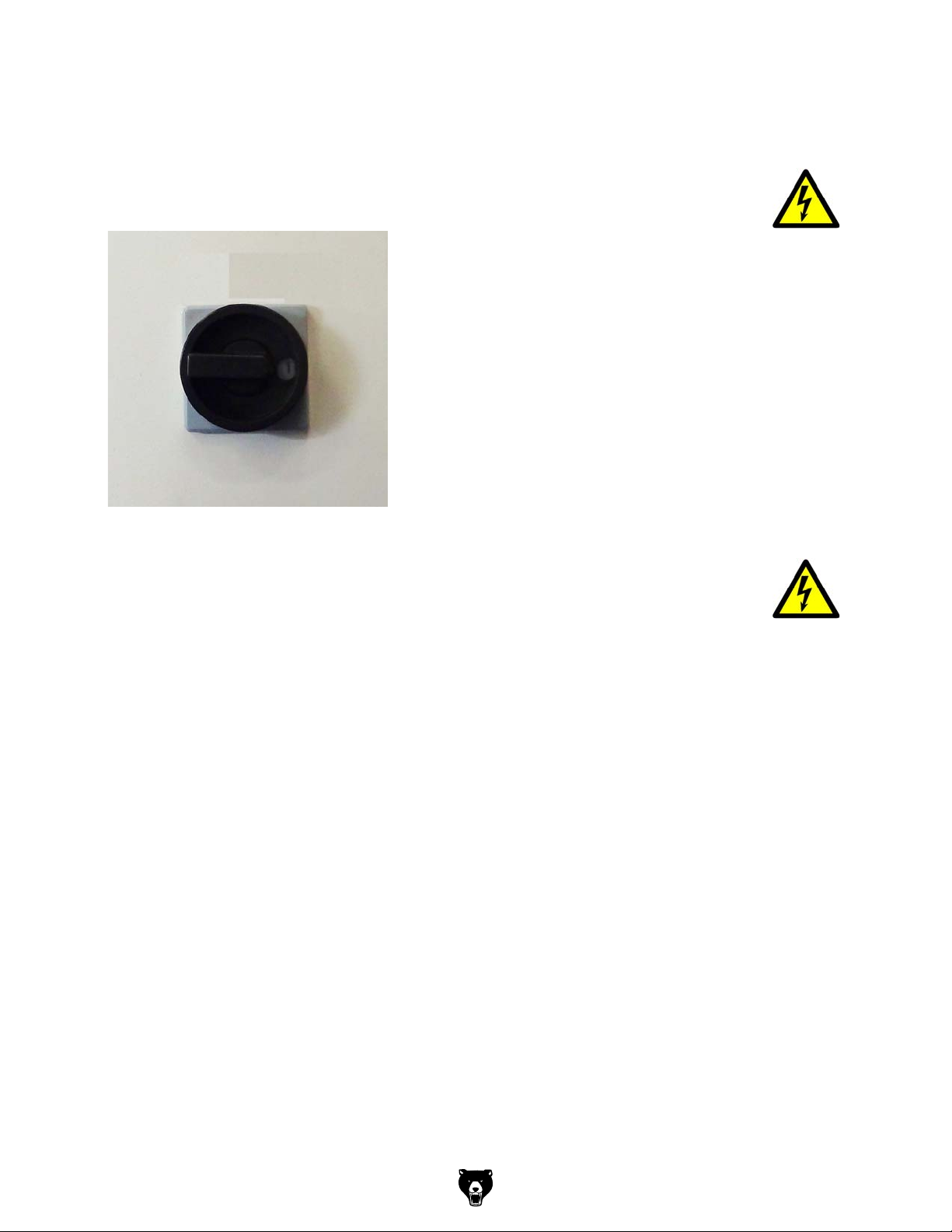
1.9.1 Lockable main switch
In the "0" position, the lockable main switch can be secured against accidental or non-authorised switching on by means of a padlock.
The power supply is interrupted by switchingoff the main plug.
Except for the areas marked by the pictogram in the margin. In these areas there might be voltage, even if the main switch is switched-off.
Img.1-1: Main switch
WARNING!
Dangerous voltage even if the main switch is switched off.
The areas marked by the pictogram might contain live parts, even if the main switch is switched
off.
Model G0876 (Mfd. Since 12/22)
-15-
Page 18
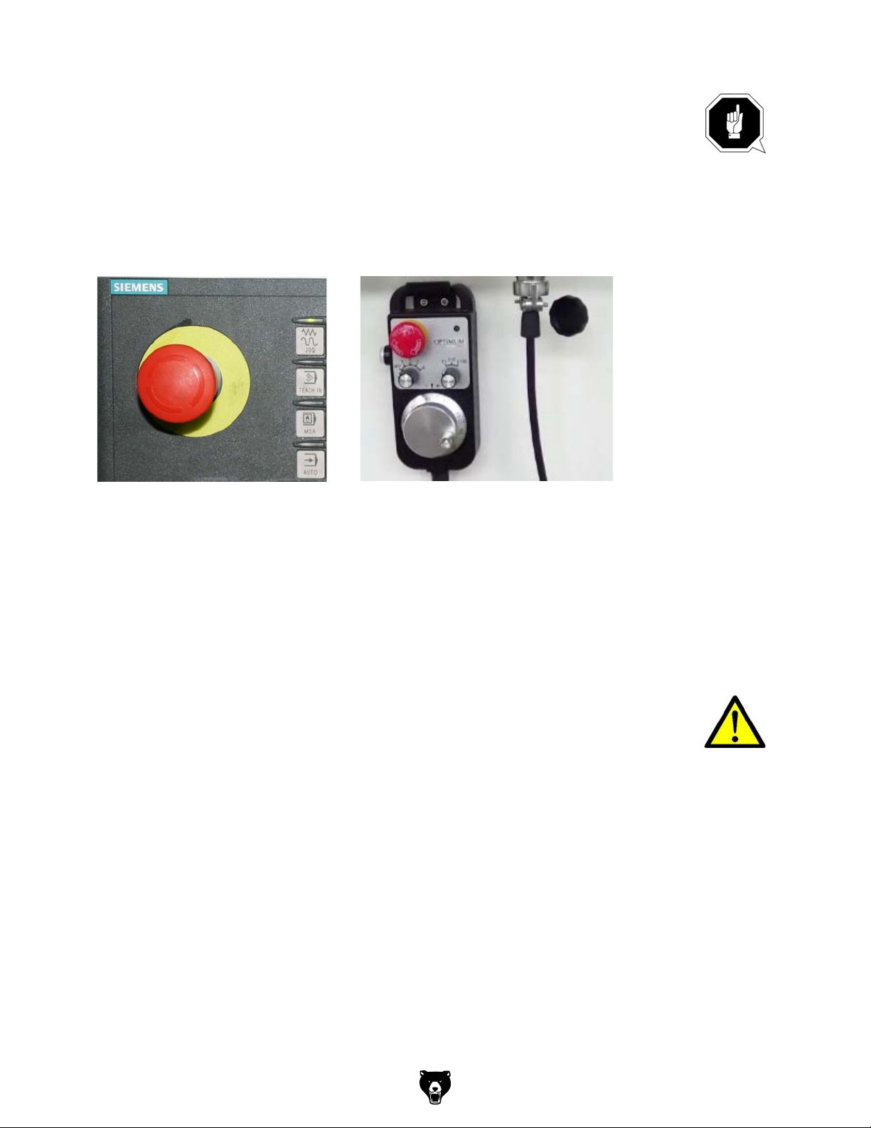
1.9.2 Emergency stop button
ATTENTION!
The EMERGENCY STOP push button immediately stops the operation of the CNC
machine.
Press the EMERGENCY STOP button only if there is a risk! If this push button is
actuated in order to switch off the CNC machine in the standard operation the tool or
workpiece might get damaged.
After having actuated the EMERGENCY STOP button, turn the knob of the particular push
button to the right in order to restart the machine.
Img.1-2: Emergency-stop push button
1.9.3 Control technical protection
WARNING!
If you bypass a controller you endanger yourself and other persons working on the CNC
machine.
injuries due to tools, workpieces or fragments hereof which are flying off at high
speed,
contact with rotating parts,
fatal electrocution,
pulling-in of clothes.
If you temporarily bypass a controller in exceptional cases (e.g. during electrical repairs), you
must continuously monitor the CNC machine.
-16 -
Model G0876 (Mfd. Since 12/22)
Page 19

1.9.4 Polycarbonate windows
Polycarbonate viewing window in chip protection, must be visual inspected by the customer
responsible personnel at regular intervals to guarantee the operational safety of the CNC
machine.
Polycarbonate viewing panes are subject to an ageing process and are classified as wear
parts.
The aging of polycarbonate windows can not be detected by visual inspection. It is therefore
necessary to replace the polycarbonate windows after a certain time.
Prolonged exposure from polycarbonate windows to cutting fluids can lead to accelerated aging, i.e. deterioration of the mechanical properties (brittleness). Coolant vapours, detergents,
greases and oils or other corrosive substances from the operator side can also lead to a deterioration of the polycarbonate windows. The result in reduced impact resistance of the polycarbonate windows.
"Cleaning and replacing of the polycarbonate windows“ on page 248
1.9.5 Prohibition, warning and mandatory labels
INFORMATION
All warning and mandatory signs must be legible. They must be checked regularly.
1.10 Safety check
Check the CNC machine at least once per shift. Inform the person responsible immediately of
any damage, defects or changes in the operating function.
Check all safety devices
at the beginning of each shift (when the machine is operated continuously),
once per day (during one-shift operation),
once per week (when operated occasionally),
after all maintenance and repair work.
Check that prohibition, warning and information signs and the labels on the CNC machine
are legible (clean them, if necessary)
and complete (replace them, if necessary).
INFORMATION
Organise the checks according to the following table;
General check
Equipment Check OK
Protective housing Switching function, firmly bolted and not damaged
Signs,
Markers
Sight window
Installed and legible
Check for mechanical damage (scratches, cracks).
cracks,
"Polycarbonate windows" on page 17
Date: checked by (signature):
Model G0876 (Mfd. Since 12/22)
-17-
Page 20
Functional check
KOk c e hCtnempiuqE
EMERGENCY STOP
push button
Switch cabinet cooling The cabinet cooling must be running.
Separating protective
equipment around the
CNC machine
After actuating an EMERGENCY STOP push button the CNC
machine must be switched off.
If the protective equipment is open it must not be possible to
start program.
Date: checked by (signature):
1.11 Personal protective equipment
For certain work personal protective equipment is required.
Protect your face and your eyes: Wear a safety helmet with facial protection when performing
work where your face and eyes are exposed to hazards.
Wear protective gloves when handling pieces or tools with sharp edges.
Wear safety shoes when you assemble, disassemble or transport heavy components.
Use ear protection if the noise level (emission) in the workplace exceeds 80 dB (A).
Before starting work make sure that the required personal protective equipment is available at
the work place.
CAUTION!
Dirty or contaminated personnel protective equipment can cause illness. It must be
cleaned after each use and at least once a week.
1.12 Safety during operation
WARNING!
Before activating the CNC machine, ensure that this will not endanger other persons or
cause damage to equipment.
Avoid any unsafe work methods:
The instructions mentioned in these operating instructions have to be strictly observed dur-
ing assembly, operation, maintenance and repair.
Do not work on the CNC machine, if your concentration is reduced, for example, because
you are taking medication.
Stay on the CNC machine until the program is termi-
nated.
The running program can be identified by means of
the signal lamp.
- Green light: Program run active
- Yellow light: Malfunction
- Red light: Actuated emergency stop push button
Img.1-3: Signal lamp
Safely and firmly clamp the workpiece in place, before switching the CNC machine on.
Never change the dosing of the coolant supply during operation.
-18-
Model G0876 (Mfd. Since 12/22)
Page 21
Never open the sliding door of the separating protective unit when the CNC
program is
running.
WARNING!
When chipping magnesia materials (aluminum-/magnesium alloys), spontaneously
inflammable or explosive particles (powder, dust, chips) might be generated, which
might cause a fire and/or explosion.
Magnesium is a dangerous material. In case of a fire with magnesium, only use
appropriate and admitted extinguishing agents. Never extinguish using water. If
burning magnesium is extinguished with water, this might lead to dangerous reactions
(hydrogen gas). Water would be decomposed in its components hydrogen (H) and
oxygen (O).
Only the following extinguishing agents are permissible:
solid extinguishing agent of fire class D (fires involving metals)
dry covering salts for magnesium
a mixture of sand and cast chips
argon (Ar) or nitrogen (N
)
2
If fine mist and smoke is generated at the workplace, suction units must be provided in
order to avoid the accumulation of ignitable mixtures and emissions.
We provide information about the specific dangers when working with and on the CNC machine
in the descriptions for these types of work.
1.13 Safety during maintenance
Inform the operators in good time of any maintenance and repair works.
Report all safety-relevant changes and performance characteristics of the CNC machine. Any
changes must be documented, the operating instructions updated and machine operators
instructed accordingly.
1.14 Disconnecting and securing the CNC machine
Turn off the main switch of the CNC machine before starting any maintenance or repair work.
Use a padlock to prevent the switch from being turned on without authorization and keep the
key in a safe place.
All machine parts as well as all dangerous voltages are switched off.
Excepted are only the positions which are marked with the adjoining pictogram. These positions
may be live, even if the main switch is switched off.
Place a warning sign on the CNC machine.
WARNING!
Live parts and moves of machine parts can injure you or others dangerously!
Proceed with extreme care if you cannot switch off
switch due to required works (e.g. functional control).
Model G0876 (Mfd. Since 12/22)
-19 -
Page 22

1.14.1 Using lifting equipment
WARNING!
The use of unstable lifting and load suspension equipment that might break under load
can cause severe injuries or even death. Observe the accident prevention regulations
issued by your Employers Liability Insurance Association or other supervisory
authorities responsible for your company.
Check that the lifting and load-suspension equipment are of sufficient load-bearing
capability and are in perfect condition.
Fasten the loads carefully.
Never walk under suspended loads!
1.14.2 Mechanical maintenance work
Remove or install protection safety devices before starting or after completing any maintenance work; this include:
covers,
safety instructions and warning signs,
grounding cables.
If you remove protective or safety devices, re-fit them immediately after the completing the
work.
Check if they are working properly!
1.15 Unattended Operation
CNC machines are designed for unattended operation. However, it may not be safe to let your
machining process run unmonitored. As it is the shop owner’s responsibility to set up the
machine safely and use best practice machining techniques, it is also their responsibility to
manage the progress of these methods. The machining process must be monitored to prevent
damage in case of a hazardous situation.
For example, if there is a risk of fire due to the machined material, an appropriate fire suppression system must be installed to reduce the risk of harm to personnel, equipment and the building. Have a specialist supplier install monitoring tools, before allowing machines to run
unattended.
It is especially important to select monitoring equipment that can immediately perform an appropriate action without human intervention to prevent an accident, should a problem be detected.
1.16 Accident report
Inform your supervisors immediately in the event of accidents, possible sources of danger
and any actions which almost led to an accident (near misses).
There are many possible causes for "near misses".
The sooner they are notified, the quicker the causes can be eliminated.
INFORMATION
We provide information about the specific dangers when working with and on the CNC machine
in the descriptions for these types of work.
1.17 Electrical system
Have the machine and/or the electric equipment checked regularly. Immediately eliminate all
defects such as loose connections, defective wires, etc.
-20-
Model G0876 (Mfd. Since 12/22)
Page 23

A second person must be present during work on live components to disconnect the power in
the event of an emergency. Disconnect the machine immediately if there is a malfunction in the
in case of failure of the power supply!
The operator of the machine must ensure that the electrical systems and operating equipment
are inspected with regards to their proper condition, namely,
by a qualified electrician or under the supervision and direction of a qualified electrician,
prior to initial commissioning and after modifications or repairs, prior to recommissioning
and at certain intervals.
The deadlines must be set so that arising, foreseeable defects can be detected in a timely manner.
The relevant electro-technical rules must be followed during the inspection.
The inspection prior to initial commissioning is not required if the operator receives confirmation from the manufacturer or installer that the electrical systems and operating equipment comply with the accident prevention regulations, see conformity declaration.
Permanently installed electrical systems and operating equipment are considered constantly
monitored if they are continually serviced by qualified electricians and inspected by means of
measurements in the scope of operation (e.g. monitoring the insulation resistance).
1.18 Inspection deadlines
Define and document the inspection deadlines for the machine.
1.19 Clamping devices for workpieces and tools
ATTENTION!
Attention when taking over existing clamping devices. Pleased thoroughly check that
the clamping device is appropriate for your CNC machine.
Only use clamping devices with a complete inherent rigidity.
Contact the manufacturer of the clamping device regarding the reuse of clamping
devices after damage to the clamping device due to collisions.
Correctly insert the workpiece and make sure that the machine is proper working
condition.
1.20 Tools and tool holding fixtures
CAUTION !
When using tools with larger diameters or at higher speeds!
The balancing of the tools has to amount to
0 - 6000 min
from a speed of 6000 min
according to DIN / ISO 1940.
-1
- G 6,3
-1
- G 2,5
Model G0876 (Mfd. Since 12/22)
-21-
Page 24

POWER SUPPLY
Before installing the machine, consider the availability and proximity of the required power supply
circuit. If an existing circuit does not meet the
requirements for this machine, a new circuit must
be installed. To minimize the risk of electrocution,
fire, or equipment damage, installation work and
electrical wiring must be done by an electrician or
qualified service personnel in accordance with all
applicable codes and standards.
or equipment damage
may occur if machine is
not properly grounded
and connected to power
The full-load current rating is the amperage a
machine draws at 100% of the rated output power.
On machines with multiple motors, this is the
amperage drawn by the largest motor or sum of all
motors and electrical devices that might operate
at one time during normal operations.
The full-load current is not the maximum amount
of amps that the machine will draw. If the machine
is overloaded, it will draw additional amps beyond
the full-load rating.
If the machine is overloaded for a sufficient length
of time, damage, overheating, or fire may result—
especially if connected to an undersized circuit.
To reduce the risk of these hazards, avoid overloading the machine during operation and make
sure it is connected to a power supply circuit that
meets the specified circuit requirements.
For your own safety and protection of
Note: Circuit requirements in this manual apply to
a dedicated circuit—where only one machine will
be running on the circuit at a time. If machine will
be connected to a shared circuit where multiple
machines may be running at the same time, consult an electrician or qualified service personnel to
ensure circuit is properly sized for safe operation.
This machine is prewired to operate on a power
supply circuit that has a verified ground and meets
the following requirements:
A power supply circuit includes all electrical
equipment between the breaker box or fuse panel
in the building and the machine. The power supply circuit used for this machine must be sized to
safely handle the full-load current drawn from the
machine for an extended period of time. (If this
machine is connected to a circuit protected by
fuses, use a time delay fuse marked D.)
Availability
Electrocution, fire, shock,
supply.
Full-Load Current Rating
Circuit Requirements for 220V
Nominal Voltage .........208V, 220V, 230V, 240V
..........................................................60 Hz
Cycle
Phase
Power Supply Circuit
Plug/Receptacle
Cord
.................................................... 3-Phase
......................... 20 Amps
........................... NEMA 15 -20
........“S”-Type , 4-Wire, 12 AWG, 300 VAC
Full-Load Current Rating at 220V ...14 .1 Amps
-22-
property, consult an electrician if you are
unsure about wiring practices or electrical
codes in your area.
Model G0876 (Mfd. Since 12/22)
Page 25

We do not recommend using an extension cord
with this machine.
cord, only use it if absolutely necessary and only
on a temporary basis.
Extension cords cause voltage drop, which can
damage electrical components and shorten motor
life. Voltage drop increases as the extension cord
size gets longer and the gauge size gets smaller
(higher gauge numbers indicate smaller sizes).
Any extension cord used with this machine must
be in good condition and contain a ground wire
and matching plug/receptacle. Additionally, it must
meet the following size requirements:
Improper connection of the equipment-grounding
wire can result in a risk of electric shock. The
wire with green insulation (with or without yellow
stripes) is the equipment-grounding wire. If repair
or replacement of the power cord or plug is necessary, do not connect the equipment-grounding
wire to a live (current carrying) terminal.
Check with a qualified electrician or service personnel if you do not understand these grounding
requirements, or if you are in doubt about whether
the tool is properly grounded. If you ever notice
that a cord or plug is damaged or worn, disconnect it from power, and immediately replace it with
a new one.
Serious injury could occur if you connect
process. DO NOT connect to power until
Grounding Instructions
This machine MUST be grounded. In the event
of certain malfunctions or breakdowns, grounding
reduces the risk of electric shock by providing a
path of least resistance for electric current.
The power cord and plug specified under “Circuit
Requirements for 220V”
has an equipment-grounding wire and a grounding prong. The plug must only be inserted into
a matching receptacle (outlet) that is properly
installed and grounded in accordance with all
local codes and ordinances (see figure below).
No adapter should be used with plug. If
plug does not fit available receptacle, or if
process. DO NOT connect to power until
on the previous page
GROUNDED
15-20 RECEPTACLE
15-20 PLUG
Current
Carrying
Grounding Pin
Blades
Serious injury could occur if you connect
machine to power before completing setup
instructed later in this manual.
Extension Cords
Typical 15-20 plug and receptacle.
machine to power before completing setup
instructed later in this manual.
machine must be reconnected for use on a
different type of circuit, reconnection must
be performed by an electrician or qualified
service personnel, and it must comply with
all local codes and ordinances.
Model G0876 (Mfd. Since 12/22)
If you must use an extension
Minimum Gauge Size ...........................10 AWG
Maximum Length (Shorter is Better).......50 ft.
-23-
Page 26

3 Assembly and commissioning
INFORMATION
The CNC-machine is delivered pre-assembled. It is delivered in a transport box.
3.1 Scope of delivery
Compare the delivery volume with the attached packing list.
Check the status of the CNC machine immediately upon receipt and claim possible damages at
the last carrier also if the packing is not being damaged. In order to ensure claims towards the
freight carrier we recommend you to leave the machines, devices and packing material for the
time being in the status at which you have determined the damage or to take photos of this status. Please inform us about any other claims within six days after receipt of delivery.
Check if all parts are firmly seated.
3.2 Transport
WARNING!
Severe or fatal injuries may occur if the machine or parts of the machine tumble or fall
down from the forklift truck or from the transport vehicle. Follow the instructions and
information on the transport box:
Centers of gravity
Load suspension points
(Marking of positions for the load
suspension point)
Prescribed transportation position
(Marking of the top surface)
Means of transport to be used
Weights
WARNING!
The use of damaged lifting and load suspension equipment without sufficient load
capacity that might break under load can cause severe injuries or even death.
Check that the lifting and load suspension equipment has sufficient load capacity and
that it is in perfect condition.
Observe the accident prevention regulations.
Fasten the loads carefully.
Never walk under suspended loads!
Check the substructure. The substructure must bear the load.
Disassemble the lateral parts of the wooden box.
The CNC machine is lifted and transported with an appropriate handling device to the instal-
lation place by means of a fork-lift truck.
Disassemble the clamping bolts which are used to fix the machine on the pallet.
-24-
Model G0876 (Mfd. Since 12/22)
Page 27

Lift the CNC machine carefully from the pallet of the transportation box by means of a crane
or a fork-lift truck.
"Total weight on page 3.
Bring the CNC machine with an appropriate handling device, e.g. Electric pallet truck or
fork-lift truck at their firm position.
Make sure that no add-on-pieces are damaged or cause paintwork is damaged during
transport.
WARNING!
The use of unstable lifting and load suspension equipment that might break under load
can cause severe injuries or even death.
3.3 Installation and assembly
3.3.1 Requirements regarding the installation site
Organize the working area around the CNC machine according to the local safety regulations.
The working area for operating, maintenance and repair must not be restricted.
INFORMATION
The main switch of the CNC machine must be freely accessible.
Model G0876 (Mfd. Since 12/22)
-25-
Page 28

3.3.2 Installation plan
Connection compressed air
3.3.3 Machine mounting
1641
Electrical supply connection
530530152
Anchor-free assembly
Align the CNC machine with a machine spirit level. The slope deviation of all levels must not
exceed 0.04/1000mm.
Adjust the height by screwing in or screwing out of the levelling screw. Screwing in the lev-
elling screw causes that the rubber plate lifts itself as on the drawing from the same element.
Fix the height adjustment by the the jackscrew with the help of the counternut.
Check the alignment of the machine after a few days of usage.
-26-
Model G0876 (Mfd. Since 12/22)
Page 29
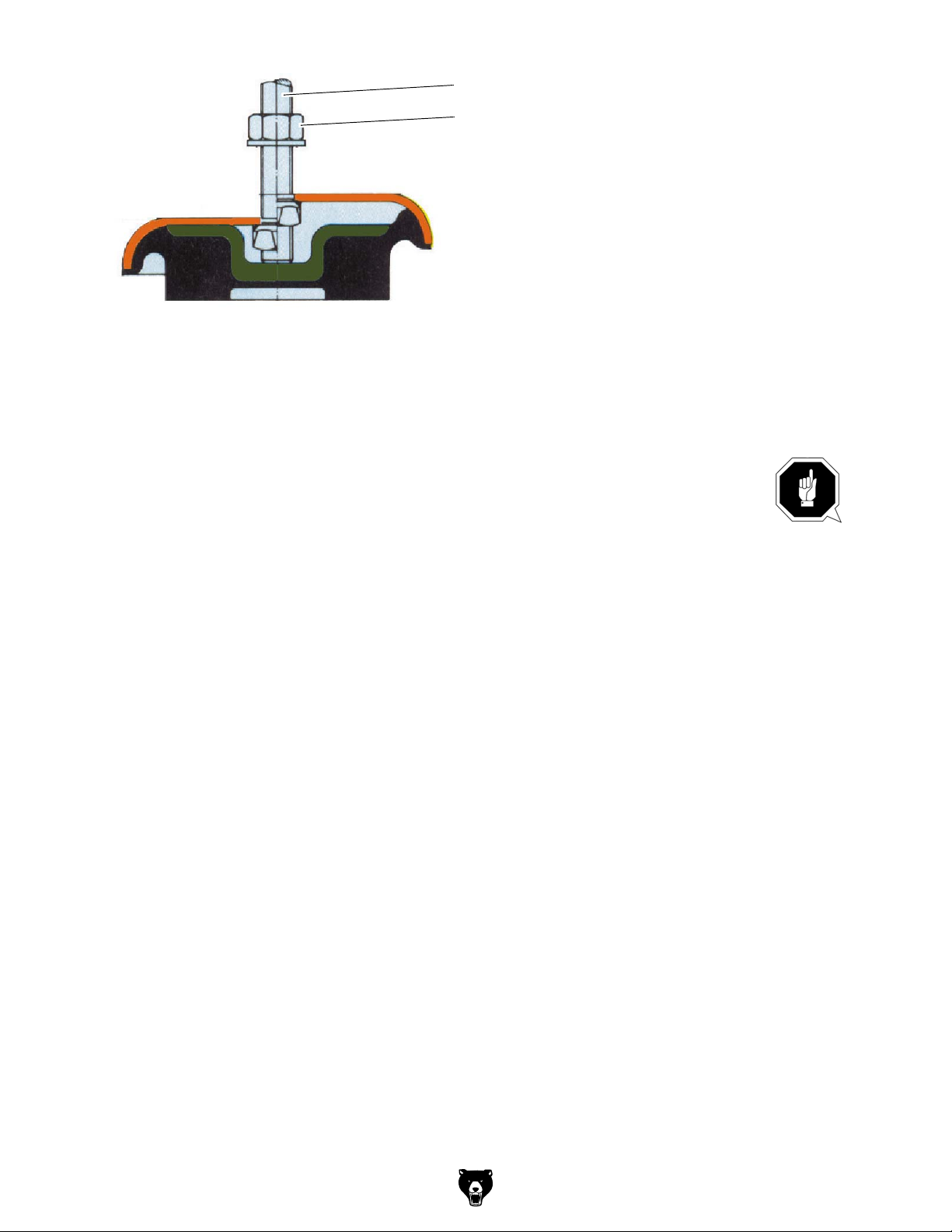
Jackscrew
Counternut
Img.3-1: Oscillating element
Anchored assembly
Use the anchored assembly in order to attain a firm connection to the ground. An anchored
assembly is always reasonable if parts are manufactured to the maximum capacity of the CNC
machine.
ATTENTION!
An insufficient rigidity of the substructure leads to superposition of vibrations between
the CNC machine and the substructure (natural frequency of the components). Critical
speeds and moves in the axis with displeasing vibrations are rapidly achieved in case of
insufficient rigidity of the whole system and will lead to bad milling results.
Check the correct alignment of the machine after a few days of usage.
3.3.4 Corrosion protection
A corrosion protection is applied on the machine table and on the guiding surfaces for trans-
port and storage. Remove the anti-corrosive agent from the CNC machine before first commissioning. Therefore, we recommend you to use paraffin.
Model G0876 (Mfd. Since 12/22)
-27-
Page 30

3.3.5 Electrical connection
Check the fusing (fuse) of your electrical supply according to the technical instructions
regarding the total connected power of the milling machine.
Firmly connect the machine.
CAUTION!
Install the connection cable of the machine in such a way that people will not stumble
over it.
Please verify if the type of current, voltage and protection fuse correspond to the values specified. A protective earth ground wire connection must be available.
With an internal EMC filter the leakage current of the frequency converter of milling spindle is
greater than 3.5 mA. We ask for due attention while executing machine tests within
the framework of industrial safety guidelines.
ATTENTION!
When delivered the machine is equipped with a plug for electrical connection. It only
serves for acceptance and test purposes. In order to operate the machine it is necessary
to remove this plug and to connect the machine directly with a power supply.
Firmly connect the CNC machine to the terminal box. It is not allowed to connect the machine
using a standard 16A CEE plug, since the stray current of the frequency converter is exceeding the admissible value of 3.5mA.
ATTENTION!
Depending on the quality of the network, there is a risk of machine malfunctions under
extreme conditions. If necessary and in order to exclude retroactive effects on the
internal power supply system, the operator should install a line filter on the machine.
Therefore, at workplaces with lots of powerful consumers, it might also be necessary to
use a system for network compensation. Please consult your electricity supplier
regarding this.
ATTENTION!
Frequency converters (drive regulators) might trigger the Fl circuit breaker of your
electrical supply. In order to avoid malfunction, an Fl circuit breaker switch sensitive to
pulse current or to universal current may be required.
ATTENTION!
Ensure that all 3 phases (L1, L2, L3) and the ground wire are connected correctly.
The neutral conductor (N) of its power supply is not connected.
-28-
Model G0876 (Mfd. Since 12/22)
Page 31

3.3.6 Current in the Protective Earth Ground Wire
The degree of the leakage current in the protective earthing conductor depends on whether the
internal EMC filter in the Emerson M200 frequency converter is used for spindle rotation speed
control or not. The standard frequency converter is fitted with an internal EMC filter. Instructions
on how to remove the internal filter is in the converter manual.
With the EMC filter, the leakage current is 15.4 mA AC 230V 50Hz (1 phase supply, phase-
neutral power supply, neutral point earthed).
Without an EMC filter, the leakage current is <1.9 mA (phase-neutral power supply, neutral
point earthed).
Therefore, a fixed earth connection is required and the minimum cross section of the protective
earthing conductor must conform to local safety regulations for devices with high leakage current. This is achieved by providing a permanent fixed earthing connection with two independent conductors, each having a cross section the same as the power supply cord or greater. To
simplify this, the converter is provided with two earth terminals. Both earthing connections are
required to comply with the standard EN 61800-5-1.
Since a direct current may be caused by the frequency converter in the protective earthing conductor, if an upstream residual current device (ELCB / RCD) is required in the network, the following guidelines must be followed:
There are three common types of FI (ELCB / RCD):
AC - to detect AC fault currents
A - to detect AC fault currents and pulsating DC fault currents (provided the DC current
reaches zero at least once every half cycle).
B - to detect AC fault currents, pulsating DC fault currents and smooth DC residual currents.
Type AC should never be used in converters.
Type A can only be used for single-phase converters.
Type B must be used for 3-phase converters.
When using an external EMC filter, to avoid false error shutdowns, a time delay of at least 50
ms is required. The leakage current can exceed the threshold trigger value for an error shutdown if the phases are not switched on at the same time.
Line systems
The CNC milling machine is designed for TN and TT line systems with a grounded neutral
point.
Prohibited operation
Operation on TN line systems with grounded external conductors is prohibited.
Operation on TT line systems without grounded neutral points is prohibited.
Operation on IT line systems is not permitted. In an IT line system, all of the conductors are
insulated with respect to the PE protective conductor – or connected to the PE protective conductor through an impedance. Operation on an IT line system is not permitted.
Permissible line supplies
Operation on TN and TT line systems
TN line system
The TN line system in accordance with IEC 60364-1 (2005) transmits the PE conductor to the
installation via a conductor. Generally, in a TN line system the neutral point is grounded There
are versions of a TN line supply with a grounded line the conductor, e.g. with grounded L1.
A TN line system can transfer the neutral conductor N and the PE protective conductor either
separately or combined.
Model G0876 (Mfd. Since 12/22)
-29-
Page 32
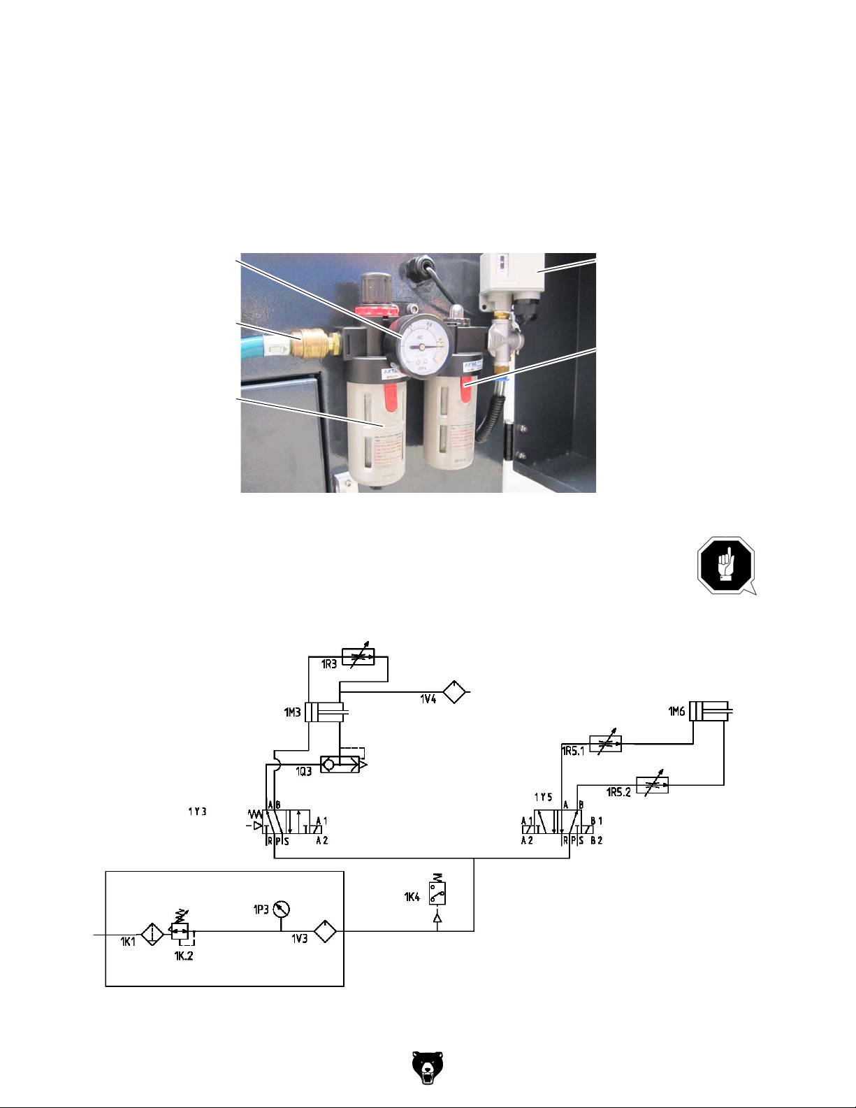
TT system
In a TT line system, the transformer grounding and the installation grounding are independent
of one another. There are TT line supplies where the neutral conductor N is either transferred –
or not.
3.3.7 Connection compressed air supply
Open the cover and connect the compressed air supply with at least 6.5 bars to the quick-
action coupling of the compressed air maintenance unit.
Adjust a pressure of 6.3 bars using the set screw of the maintenance unit.
Manometer
Compressed air supply
Compressed air drainage
Img.3-2: Compressed air maintenance unit
ATTENTION!
In order to ensure a failure-free operation of the machine it is necessary that the required
air pressure is continuously applied on the machine at constant quality. In case of
insufficient air supply, for instance interruptions occur during tool change.
Air pressure switch
Pneumatic oiler
Cylinder tool clamping
Cylinder tool clamping
Solenoid valve
Compressed air service unit
Filter
Pressure controller
Manometer
Pneumatic oiler
Throttle valve
Drip feed lubricator
Cylinder tool changer
Throttle valve
Throttle valve
Quick exhaust valve
Solenoid valve
Air pressure switch
-30-
Model G0876 (Mfd. Since 12/22)
Page 33

3.4 First commissioning
3.4.1 Refilling the cooling lubricant
INFORMATION
The CNC machine is delivered without cooling lubricant.
Fill the coolant / lubricant tank with an appropriate cooling lubricant via the machining room
CNC machine.
Img.3-3: Level indicator coolant / lubricant
ATTENTION!
Failure of the pumps in case of dry running. The pumps are lubricated by the cooling
lubricant. Do not start up the pumps without cooling lubricant.
"Cooling lubricants“ on page 243
Level indicator
INFORMATION
Use a water-soluble environmentally friendly emulsion as cooling lubricant procured
from a specialist retailer.
Make sure that the cooling lubricant is properly absorbed.
Respect the environment when disposing of lubricants and coolants. Follow the
manufacturer’s disposal instructions.
3.4.2 Cooling lubricants
INFORMATION
The lathe is lacquered with a one-component paint. Consider this fact when selecting your cooling lubricant.
The company Grizzly Industrial, Inc. does not assume any guarantee for subsequent
damages due to unsuitable cooling lubricants.
The flashpoint of the emulsion must be higher than 140°C.
When using non-water-miscible cooling lubricants (oil content > 15%) with a flashpoint, ignitable
aerosol air mixtures might develop. There is a potential danger of explosion.
The selection of cooling lubricants and slideway oils, lubricating oils or greases as well as their
care are being determined by the machine operator or operating company.
Therefore, Grizzly Industrial, Inc. cannot be held liable for machine damages caused by
unsuitable coolants and lubricants as well as by inadequate maintenance and servic-ing of the
coolant. In case of problems with the cooling lubricant and the slideway oil or grease, please
contact your mineral oil supplier.
Model G0876 (Mfd. Since 12/22)
-31-
Page 34

CAUTION!
The cooling lubricant needs to be checked at least weekly, including during downtimes,
with regard to its concentration, ph-value, bacteria and fungal decay.
"Cooling lubricants and tanks" on page 251
We would like to ask you to have the following machine-related properties of the cooling lubricant confirmed in writing by the manufacturer of the cooling lubricant.
The products must comply with the provisions of the current statutory regulations and the
employers' liability insurance association.
Request documentation for the products such as the product description VKIS and EC
safety data sheet from the cooling lubricants manufacturer. The EC safety data sheet gives
you information about the water hazard class.
They need to be environmentally friendly and workplace-friendly. Thus, they need to be free of
nitrite, PCB, chlorine and nitrosatable diethanolamine (DEA), according to TRGS 611.
The manufacturer should be able to provide a certificate concerning skin tolerance.
The mineral oil content according to DIN 51417 should be at least 40% in the concentrate.
If possible, it should be universally applicable for all chippings and materials.
Long service life of the emulsion e.g. long-term stable and resistant to bacteria.
Safe corrosion protection according to DIN 51360/2.
Re-emulsifiable and non-adhesive according to VKIS sheet 9: Sticking and residue behav-
iour.
It should not attack the varnish of the machine according to VDI 3035.
It should not attack any machine elements (metals, elastomers).
Low foaming behaviour of the emulsion.
It should be as finely dispersed as possible in order to avoid clogging in the needle slot
screen.
-32-
Model G0876 (Mfd. Since 12/22)
Page 35
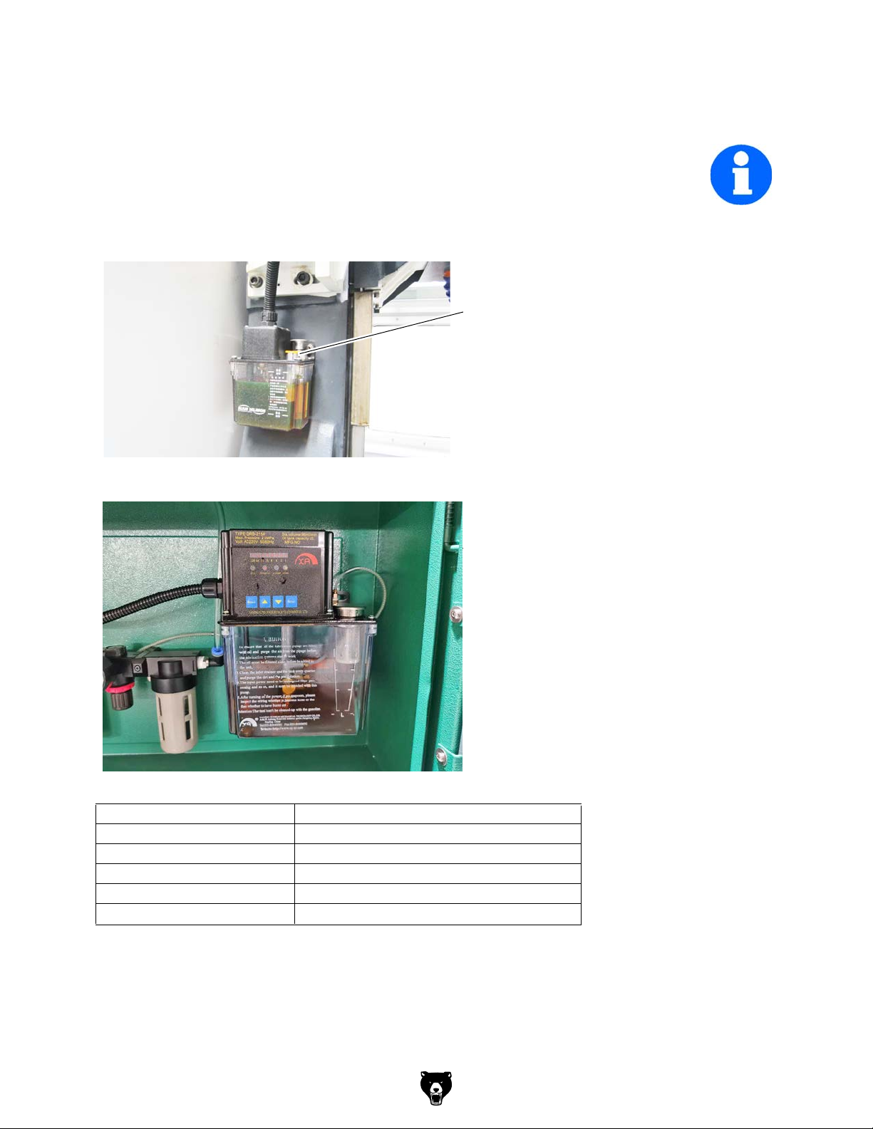
3.5 Refill central lubrication system
The CNC machine is equipped with a central lubrication system.
INFORMATION
The CNC milling machine is delivered without lubricating oil. The central lubrication system is
depending on the model in the working area on the column of the spindle or at other locations.
Refill the reservoir with oil through the fill cap.
"Cooling lubricants“ on page 243
Fill cap
Img.3-4: Old type of central lubricating system
Img.3-5: Second type of central lubricating system
Type: DRB 12210
Pressure 2.5 MPa
Power 10 Watt
Connection 230V ~ 50Hz / 115V ~ 60Hz
filling quantity 2 litres
discharge volume 96 ml / min
Fill cap
Model G0876 (Mfd. Since 12/22)
-33-
Page 36

Setting the jumpers
Factory setting
30
5
prohibited
15
40
65
10
75
20
30
20
45
70
Switch-on time (seconds)
5
10
25
50
75
Interval (minutes)
30
55
80
35
60
85
90
INFORMATION
The factory setting is 75 minutes as the interval between lubrication cycles and
30 seconds for the ON period of the lubrication oil pump.
Operating indicator lights DRB 12210
Status Description Note:
In Operation The red LED lights Oil is supplied to the lubrication points
Idling cycle The red LED flashes Pause between the lubrication cycles
The pressure relief valve of the central lubrication system is factory set to a pressure of 2.5
MPa.
95
100
105
110
-34-
Model G0876 (Mfd. Since 12/22)
Page 37

3.6 Functional test and controls
Rotation coolant pump
Check the direction of rotation of the CNC machine. There must be a right-handed rotating
field. If the direction of rotation is wrong, exchange two of the three phase conductors. At
this, the correct direction of rotation only refers to the drive of the cooling lubricant pumps.
INFORMATION
The rotational direction of the coolant pump can not be checked in the built in state. If no coolant flows the rotational direction of the coolant pump may be wrong.
Proceeding to set the direction of rotation:
"Turning on the CNC- machine“ on page 55
Close the sliding door and turn on the coolant supply.
Check if cooling agent flows.
Img.3-6: Coolant supply
Coolant supply
WARNING!
Never change the dosing of the cooling lubricant supply when a program is running.
If no coolant is flowing and thus the rotational direction of the coolant pump may be wrong,
- first check the coolant level in the coolant tank,
- and then replace two of three phases (e.g. L1 and L2) in the control cabinet on the circuit
breaker of the engine of coolant pump against each other.
WARNING!
Swapping the phases must be performed by a qualified electrician!
Check all oil levels and filling levels of lubricants in the reservoirs.
Perform a safety test.
3.6.1 Warming up the machine
ATTENTION!
If the CNC machine and in particular the milling spindle is immediately operated at
maximum load when it is cold it may result in damages.
If the machine is cold, e.g. directly after having transported the machine, it should be
warmed up at a spindle speed of only 500 1/min for the first 30 minutes.
Model G0876 (Mfd. Since 12/22)
-35-
Page 38

4 General information about CNC
4.1 Compensation of geometry
It is necessary to be able to measure any currently actual position of the CNC-controlled axis in
order to perform tool moves on workpieces.The measured value is related to a machine fixed
zero position and is compared to the target position which is predefined by the programs.
Required knowledge:
coordinate systems of the machine and workpiece
reference points of the machine, tool and workpiece
type of distance measurement
options of dimensioning and dimension compensation
Basics:
For chip removal relative moves between the tool and the workpiece are required. For programming all moves are related to the resting workpiece.
4.2 Coordinate systems on CNC-machine tools
Types of coordinate systems
Coordinate systems allow the exact description of all points on a working plane, respectively in
an area.
Generally they are divided into
Cartesian coordinate system and
the polar coordinate system
4.2.1 Cartesian coordinate system
A Cartesian coordinate system also called a rectangular coordinate system possesses two
coordinate axes (two-dimensional Cartesian coordinate system) or also three coordinate axes
(three-dimensional Cartesian coordinate system) which are perpendicular to one another in
order to exactly describe the points.
On a two-dimensional Cartesian coordinate system, e.g. on the X, Y-coordinate system, each
point is clearly defined on the plane by indicating the coordinates (X,Y).
The distance from the Y-axis is called the X-coordinate and the distance from the X-axis is
called Y-coordinate. Those coordinates may possess positive or negative algebraic signs.
The three-dimensional Cartesian coordinate system is required to display and determine the
position of special workpieces, e.g. milling parts.
In order to clearly describe a point in the space, three coordinates are required which are
named according to the corresponding axes X-, Y- or Z-coordinates.
Such three-dimensional coordinate systems with positive and negative areas on the coordinate
axis allow the exact description of any locations, e.g. in the working area of a milling machine,
independent from where the zero point of the workpiece is set.
-36-
Model G0876 (Mfd. Since 12/22)
Page 39
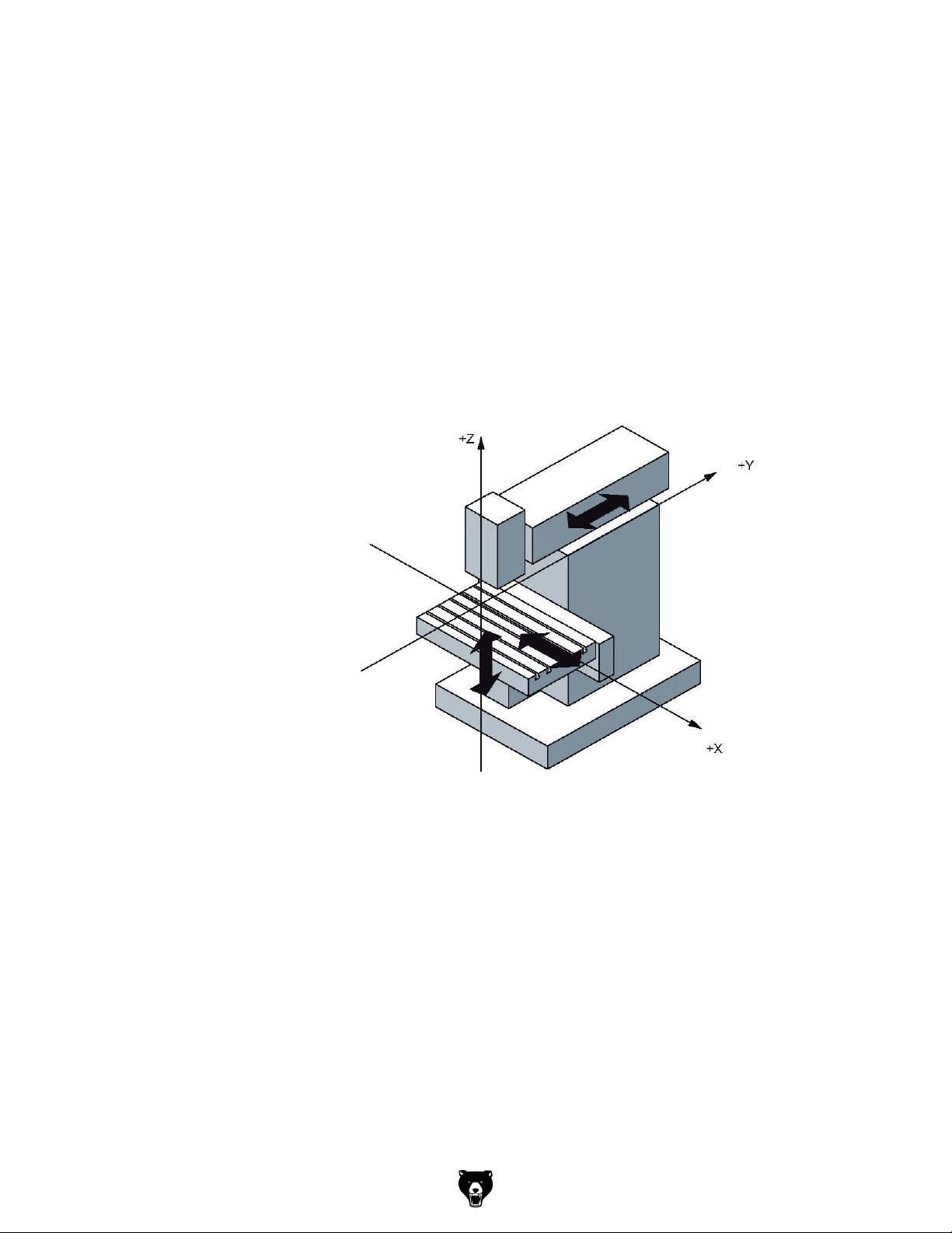
4.2.2 Polar coordinate system
In the Cartesian coordinate system a point is described by e.g. its X- and Y-coordinate. For
rotation-symmetric outlines, e.g. circular drilling images the required coordinates can only be
calculated with considerable effort.
In the polar coordinate system a point is described by means of its distance (radius r) to the
coordinate origin and its angle (a) to the defined axis. The angle (a) is related to the X-axis of
the X, Y coordinate system. In opposite direction it is negative.
4.2.3 Machine coordinate system
The machine coordinate system of the CNC machine tool is determined by the manufacturer. It
cannot be changed. The position of the origin point for the machine coordinate system, also
called machine zero point cannot be changed.
Any tool moves are generally defined in a standardized, right-handed coordinate system.
Turns from +X to +Y are created in +Z direction, which result in a right-handed screw.
Z-axis:
According to the standard it is
equal to the working spindle or
continues in positive direction
starting from the workpiece.For
milling it continues directed to the
spindle perpendicular on the
clamping surface (only for perpendicular milling machines) for several spindles one main spindle is
determined.
X-axis:
Continues horizontally and parallel to the clamping surface
for vertical Z-axis: +X to the right
for horizontal Z-axis: +X to the left
.
Img.4-1: Vertical Z-axis
Y-axis:
At a right angle to the Z- and X- axis in a way that a right-handed coordinate system is resulting
4.2.4 Workpiece coordinate system
The workpiece coordinate system is determined by the programmer. It can be changed. The
location of the origin point for this workpiece coordinate system, also called workpiece origin
point is generally user-defined.
Model G0876 (Mfd. Since 12/22)
-37-
Page 40

4.2.5 Rotary axes and secondary axes
NC machines with rotary table or swivel head
Rotary axis: A B C
Positive turn around X, Y, Z (right- hand-rule)
NC machines with several feed axes
Secondary axis: U V W
Parallel to the X-,Y-,Z-axis
4.3 NC mathematics
4.3.1 Basics of the coordinate calculation
For the CNC programming the corresponding points of the outline which is to be machined
need to be entered. In most cases if the drawing is suitable for NC purposes, it is possible to
directly transfer these coordinate points from the drawing. In some cases it may be necessary
to calculate the coordinates.
In the frame of the automation those coordinates are calculated by an NC programming system at external working places and the data are directly transferred to the machine. Therefore,
in most cases the NC programming is directly performed on the product (3D pattern) in the construction or in the process engineering department.
For the computer-aided programming the switch and path information are entered over the keyboard in the dialogue using the menu technique.
4.3.2 Parameters of a triangle
In order to calculate the missing coordinates the relations valid for a triangle are very useful.
There are several options to describe a triangle. Some of the following parameters e.g. corners,
angles or sides are being used.
4.3.3 Angle on a triangle
The angles on a triangle determine the type of triangle. Depending on the size of the individual
angles we distinguish between acute-angle, obtuse angle or rectangular triangles.
On triangles the following relation is applied:
the sum of the angles a, b and g in a triangle always amounts to 180°.
a + b + g = 180°
If two angles are known it is possible to determine the third unknown angle by means of this formula.
Rectangular triangle
The rectangular triangle has a special meaning in the analytic geometry as the sides of such a
triangle are having a definite mathematic relation to one another.
On a rectangular triangle the single sides are specially named.
The longest side is located opposite to the right angle and is named hypotenuse.
The two sides of the triangle which are forming the right angle are named cathetus.
The side opposite the angle a is named opposite leg.
The side adjacent to the angle a is named adjacent leg.
On a rectangular triangle the right angle is described by an quarter circle and a point in the
angle.
In a rectangular triangle it applies:
In a rectangular triangle you can calculate the missing leg if the other leg lengths are known. To
do so, use the Pythagorean theorem.
-38-
Model G0876 (Mfd. Since 12/22)
Page 41

The Greek Pythagoras (from about 580 to 496 before Jesus Christ) had been the first person to
prove the following mathematic relation which had later on been named the Pythagorean the-
a
b
orem.
The sum of the cathetus square is equal to the hypotenuse square and expressed as a
equation:
a² + b² = c²
c
4.4 Trigonometric functions
The trigonometric functions describe the relations between the angles and the sides of a rectangular triangle. With the help of these trigonometric functions it is possible to calculate
unknown leg lengths with an unknown angle and a known leg. It is depending on which side
and which angle are known in order to choose the appropriate trigonometric function e.g. the
sinus function, the cosine function or the tangent function.
For the calculation of unknown legs the corresponding equation needs to be transformed as
described in the following example:
Known are: the angle and the length of the adjacent leg
Looking for: the length of the opposite leg
It applies: tan alpha = opposite leg / adjacent leg
The results is:
opposite leg = adjacent leg x tan alpha
Model G0876 (Mfd. Since 12/22)
-39-
Page 42

5 User interface, machine control panel
5.1 Screen arrangement
1
8
2
9
3
10
4115126
13
7
Excerpt from the manual of the operating instructions for "SINUMERIK 808D OPM Operation"
1
2
5
6
7
3
8
10
11
12
Img.5-1: Screen arrangement
4
9
13
Status area Application area
Active operating area Actual value window
Active operating mode T, F, S window
Alarm and message prompt area
Operating window with program block
Mode Display / Data Display
Tip and softkey area
Current time and date
Program file name
Program status indication
Active program control modes
Information line
Horizontal softkey bar
Vertical softkey bar
-40-
Model G0876 (Mfd. Since 12/22)
Page 43

5.2 Elements on the PPU (Panel Processing Unit) front
1
2
3
4
Img.5-2: Panel Processing Unit
Elements on the PPU
Excerpt from the manual of the operating instructions for "SINUMERIK 808D OPM Operation"
Vertical and horizontal softkeys
Calls specific menu functions
Return key
Returns to the next higher-level menu.
Description
Menu extension key
No function is assigned to this key. Reserved for future use.
Alphabetic and numeric keys
You use these keys to enter characters or NC commands.
Holding down <SHIFT> while pressing an alphabetic or numeric key
allows you to enter the upper character shown on the key.
Model G0876 (Mfd. Since 12/22)
-41-
Page 44

Elements on the PPU
5
6
Excerpt from the manual of the operating instructions for "SINUMERIK 808D OPM Operation"
Description
Control keys
Shift key
Control key
Alternate key
Space key
Backspace key
Deletes a character selected to the left of the cursor.
Delete key
Deletes the selected file or character.
Insert key
Tab key
• Indents the cursor by several characters.
• Toggles between the input field and the selected program name.
Input key
• Confirms your entry of a value.
• Opens a directory or program.
Alarm cancel key
Cancels alarms and messages that are marked with this symbol
-42-
Model G0876 (Mfd. Since 12/22)
Page 45

Elements on the PPU
7
8
9
Excerpt from the manual of the operating instructions for "SINUMERIK 808D OPM Operation"
Description
Menu function key
Opens the wizard main screen.
Help key
Calls the context-sensitive help for the selected window, alarm,
message, machine data, setting data, or end-user wizard.
Cursor keys
Cursor keys
up/down/left/right keys
Next window key
No function is assigned to this key. Reserved for future use.
End key
Moves the cursor to the end of a line.
Page up key
Scrolls upwards on a menu screen
Page down key
Scrolls downwards on a menu screen
Selection key
• Toggles in selection lists and selection fields between several
options.
• Enters the "Set-up menu" dialog at NC start-up.
Model G0876 (Mfd. Since 12/22)
-43-
Page 46

Elements on the PPU
101112
Excerpt from the manual of the operating instructions for "SINUMERIK 808D OPM Operation"
Description
Operating area keys
Opens the "Machine" operating area
Opens the "Program" operating area
Opens the "Offset" operating area
Opens the "Program" operating area
USB interface
Status LEDs
Pressing this key opens the "Alarm" operating area.
Holding down <SHIFT> while you press this key opens the "System"
operating area.
Enables user's extension application, for example, to generate user
dialogs with the EasyXLanguage function.
For more information about this function, refer to the SINUMERIK 808D
Function Manual.
Connects to a USB device
Examples:
• Connects to an external USB memory sticker to transfer data
between the USB sticker and the CNC.
• Connects to an external USB keyboard for use as an external NC
keyboard.
LED "POK"
Lights up green: The power supply for the CNC is switched on.
LED "RDY"
Lights up green: The CNC is ready for operation.
LED "TEMP"
Unlit: The CNC temperature is within the specified range.
Lights up orange: The CNC temperature is out of range.
-44-
Model G0876 (Mfd. Since 12/22)
Page 47

5.2.1 Key combination
Excerpt from the manual of the operating instructions for "SINUMERIK 808D OPM Operation"
Element Description
<ALT> + <X> Opens the "Machine" operating area
<ALT> + <V> Opens the "Program" operating area
<ALT> + <C> Opens the "Offset" operating area
<ALT> + <B> Opens the "Program" operating area
<ALT> + <M>
<ALT> + <N>
<SHIFT> +
<ALT> + <H>
<ALT> + <L>
<ALT> + <S>
<=>
<CTRL> + <B> Selects text in program blocks.
<CTRL> + <C> Copies the selected text.
<CTRL> + <D> Shows pre-defined slides on the screen.
<CTRL> + <P> Captures screens
<CTRL> + <R> Restarts the HMI
<CTRL> + <S> Saves start-up archives
Opens the "Alarm" operating area
Opens the "System" operating area
Calls the online help system.
Enables input of lowercase letters.
Applicable only when the user interface language is Chinese.
Calls the input method editor for entering Chinese characters.
Calls the pocket calculator. Note that this function is not applicable in
MDA mode.
Model G0876 (Mfd. Since 12/22)
-45-
Page 48
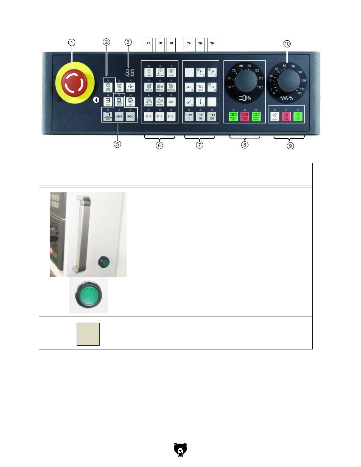
5.3 Controls on the machine control panel
1
89
10
5
6
7
2
Img.5-3: Machine control panel
Controls on the machine control panel
12
Element Function
34
Drive voltage
Push button with indicator light
• Indicator light On, drive voltage activated
• Indicator light Off, drive voltage deactivated
-46-
K11
Manual tool change
Enables or disables the manual tool change.
The manual tool change is only possible with the sliding door open.
Model G0876 (Mfd. Since 12/22)
Page 49

Excerpt from the manual of the operating instructions for "SINUMERIK 808D OPM Operation"
1
2
3
4
5
Element Description
<Emergency stop button>
Activate the button in situations where
• life is at risk.
• there is the danger of a machine or workpiece being damaged.
All drives will be stopped with the greatest possible braking torque.
Handwheel key (with an LED status indicator)
Controls the axis movement with external handwheels.
Tool number display
Displays the current tool number
Operating mode keys (all with LED status indicators)
Operating mode "JOG"
Operating mode "REF. POINT" (reference point approach)
Operating mode "AUTO" (automatic mode)
Operating mode "MDA"
Manual program input, automatic execution
Program control keys (all with LED status indicators)
Program test key
Disables the output of setpoints to axes and the spindle. The
control system only "simulates" the traverse movements in order to
verify the correctness of the program.
Conditional stop key
Stops the program at every block in which miscellaneous function
M01 is programmed.
Model G0876 (Mfd. Since 12/22)
-47-
Page 50
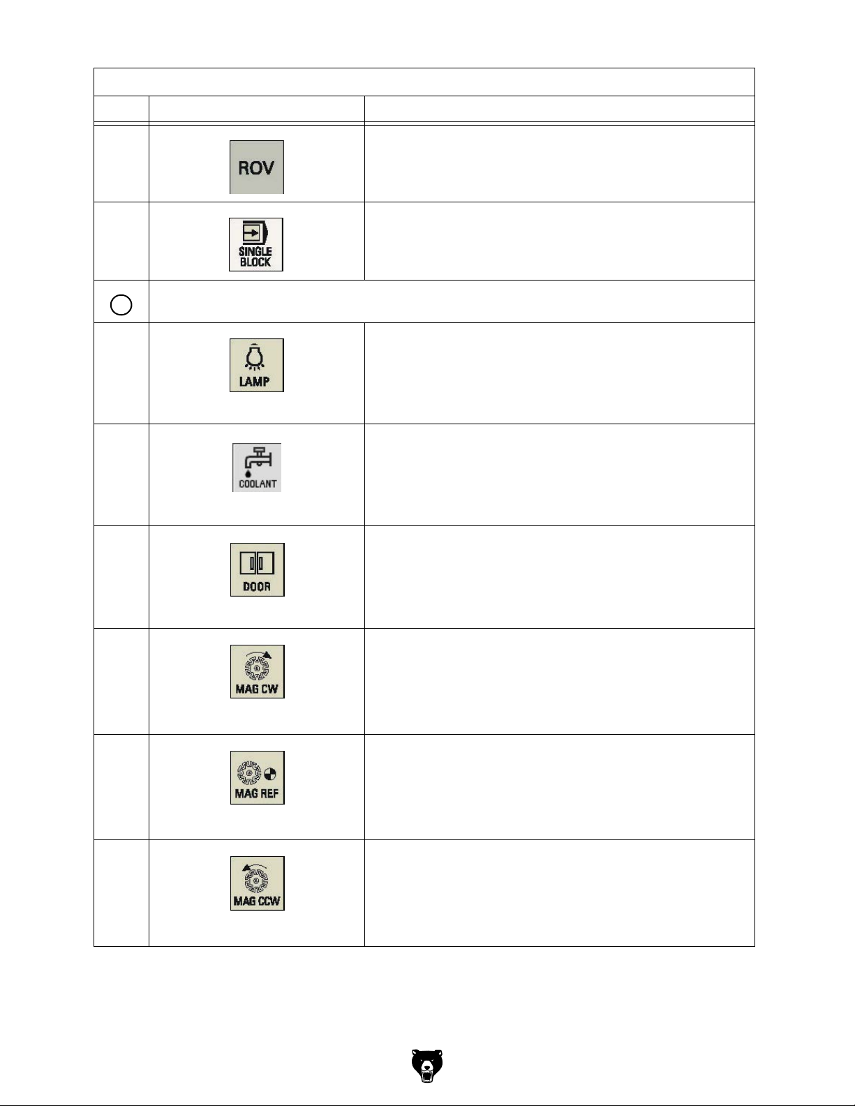
Excerpt from the manual of the operating instructions for "SINUMERIK 808D OPM Operation"
6
Element Description
Rapid override key
Adjusts axis feedrate override
Single block key
Activates single block execution mode
User-defined keys (all with LED status indicators)
Machine luminaire control key
Pressing this in any operating mode switches on/off the machine
luminaire.
LED on: The machine luminaire is switched on.
LED off: The machine luminaire is switched off.
Coolant control key
Pressing this key in any operating mode switches on/off the coolant
supply.
LED on: The coolant supply is switched on.
LED off: The coolant supply is switched off.
Safety door control key
When all axes and the spindle stop operation, pressing this key
unlocks the safety door.
LED on: The safety door is unlocked.
LED on: The safety door is locked.
Clock wise magazine rotation
(active only in JOG mode)
Pressing this key rotates the magazine clockwise.
LED on: The magazine rotates clockwise.
LED off: The magazine stops clockwise rotation.
Reference point approach of the magazine
(active only in JOG mode)
Pressing this key approaches the magazine to the reference point.
LED on: The magazine is reference point approached.
LED off: The magazine is not yet referenced.
Counterclockwise magazine rotation
(active only in JOG mode)
Pressing this key rotates the magazine counterclockwise.
LED on: The magazine rotates counterclockwise.
LED off: The magazine stops counterclockwise rotation.
-48-
Model G0876 (Mfd. Since 12/22)
Page 51

Excerpt from the manual of the operating instructions for "SINUMERIK 808D OPM Operation"
7
Element Description
Forward rotation of the chip conveyor
(active only in JOG mode)
Pressing this key in any operating mode starts the forward rotation
of the chip conveyor.
LED on: The chip conveyor starts forward rotation.
LED off: The chip conveyor stops rotation.
INFORMATION
The G0876 does not have a chip conveyor. Therefore,
the key has no function.
Reverse rotation of the chip conveyor
(active only in JOG mode)
Keeping pressing this key in any operating mode rotates the chip
conveyor in reverse order.
Releasing the key changes the chip conveyor to the previous
forward rotation or stop state.
LED on: The chip conveyor starts reverse rotation.
LED off: The chip conveyor stops reverse rotation.
INFORMATION
The G0876 does not have a chip conveyor. Therefore,
the key has no function.
Axis traversing keys
User-defined keys
INFORMATION
The <K11> button is associated with the manual tool
change.
X axis key
Traverses the X axis in the positive direction.
X axis key
Traverses the X axis in the negative direction.
Z axis key
Traverses the Z axis in the negative direction.
Z axis key
Traverses the Z axis in the positive direction.
Model G0876 (Mfd. Since 12/22)
-49-
Page 52

Excerpt from the manual of the operating instructions for "SINUMERIK 808D OPM Operation"
8
9
Element Description
Y axis key
Traverses the Y axis in the positive direction.
Y axis key
Traverses the Y axis in the negative direction.
Rapid traverse overlay key
Traverses the selected axis at rapid traverse speed while pressing
the relevant axis key.
Inactive key. No function is assigned to this key.
Incremental feed keys (with LED status indicators)
Sets increments desired for the axis to traverse.
Spindle control keys
Starts the spindle counterclockwise
Stops the spindle
Starts the spindle clockwise
Spindle speed override switch
Makes the spindle rotate at the specified speed override.
Program state keys
-50-
Model G0876 (Mfd. Since 12/22)
Page 53

Excerpt from the manual of the operating instructions for "SINUMERIK 808D OPM Operation"
10
Element Description
Cycle stop key
Stops the execution of NC programs
Cycle start key
Starts the execution of NC programs
Reset key
Resets NC programs
Cancels alarms that meet the cancel criterion.
Feedrate override switch
Traverses the selected axis at the specified feed rate override.
5.4 Protection levels
SINUMERIK 808D provides a concept of protection levels for enabling data areas. Different
protection levels control different access rights.
The control system delivered from SIEMENS is set by default to the lowest protection level 7
(without password).
If the password is no longer known, the control system must be reinitialized with default
machine data. All passwords are then reset to default passwords for this software release.
ATTENTION!
Before you boot the control system with default machine data, make sure that you
havebacked up your data; otherwise, all data is lost after rebooting with the default
machine data.
Protection level Locked by Area
0 Siemens password Siemens, reserved
1 Manufacturer password Machine manufacturers
2 Reserved
3 - 6 End-user password
(Default password: "CUSTOMER")
End users
7 No password End users
Model G0876 (Mfd. Since 12/22)
-51-
Page 54

Protection level 1
Protection level 1 requires a manufacturer password. With this password entry, you can perform the following operations:
Entering or changing all machine data
Conducting NC commissioning
Protection level 3-6
Protection level 3-6 requires an end-user password. With this password entry, you can perform
the following operations:
Entering or changing part of the machine data
Editing programs
Setting offset values
Measuring tools
Protection level 7
Protection level 7 is set automatically if no password is set and no protection level interface signal is set. The protection level 7 can be set from the PLC user program after you set the bits in
the user interface.
In the menus listed below the input and modification of data depends on the set protection
level:
Tool offsets
Work offsets
Setting data
RS232 settings
Program creation / program correction
5.4.1 Passwords
INFORMATION
Usually the machine operator does not need to change the password.
5.4.2 Change passwords
Step 1
The service mode is opened with the appropriate key combination. In the service mode, the
password can be activated and deactivated.
Press Shift+ System Alarm
Step 2
Set
password
Change
password
Delete
password
Enter customer’s or manufacturer’s password.
Change customer’s or manufacturer’s password.
Delete customer’s or manufacturer’s password.
Set
password
Change
password
Delete
password
-52-
Model G0876 (Mfd. Since 12/22)
Page 55
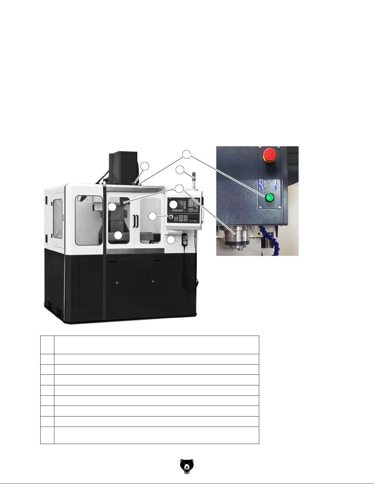
6 Operation
6.1 Safety
Commission the CNC machine only under the following conditions:
The CNC machine is in proper working order.
The CNC machine is used as intended.
The operating manual is followed.
All safety devices are installed and activated.
Eliminate or have all malfunctions rectified promptly. Stop the CNC machine immediately in the
event of any failure in operation and make sure that it cannot be started up accidentally or without authorisation. Notify the person responsible immediately of any modification.
"Safety during operation“ on page 18
6.2 Control and indicating elements
Img.6-1:
No
.
1
10
3
10
7
8
2
9
11
10
Designation
1 Touch-switch to release and clamp the tool.
2 Milling spindle
3 Tool change system incl. magazine disk
7 Milling table
8 Signal lamp (if the indicator lamp lights up green --> CNC- program is running)
9 Machine control panel
10 Emergency-stop button
Handwheel for manual travelling with Emergency Stop push button and acknowl-
11
edgement button
Model G0876 (Mfd. Since 12/22)
-53-
Page 56

Signal lamp
Pos.
1
Colour Meaning
No.
6.3 Operational modes
Manually controlled operation
The manually controlled operation is possible in the "JOG" and "MDA" operating modes. Refer
to chapter "Manual mode" of the operating instructions of "SINUMERIK 808D".
In JOG mode, you can perform the following machining operations:
Measuring tools
Measuring the workpiece
Setting parameters for face machining of a workpiece blank
Setting the spindle speed and direction, activating other M function and changing the tool,
Setting the axis positions in the relative coordinate system.
In MDA mode, you can create programs, load existing programs from directories in the "Program Manager" into the MDA buffer, or execute the current program.
Automatic mode
2
3
Red Lights up when activity the EMERGENCY STOP push button
1
Orange
2
Green
3
Lights up when a disturbance or in set-up operation such as
opened safety housing
Lights up in the operating mode "automatic mode" resp. "pro-
gram run"
Refer to chapter "Setup machine" of the operating instructions for "SINUMERIK 808D".
6.4 Programming
For further working steps please proceed as described in the operating instructions "Part programming, system, programming and cycles“ for SINUMERIK 808D.
Manual resp. part programming:
For this kind of programming, the programs must be created manually and entered in the control unit. The direct programming in the DIN-Code is a complex method which requires lots of
skills. Nowadays this task is mostly taken over by CAD/CAM systems which directly create an
operating program using a graphical user interface.
Automatic programming:
Construction data are transmitted (semi-) automatically to an executable program by means of
the CAD/CAM program (for instance a 3D-CAD program including downstream co-processor).
For this kind of programming, a 3D model is designed using a PC. The motion-sequence of the
machine is calculated by means of an operating sequence which is predefined by the user.
These programs access the tool data base which includes all tool parameters (speed, feed,
diameter, etc.). Due to this systematic program structure, the user is able to create a complete
program in a short period of time without having any knowledge of the individual program commands and their syntax.
-54-
Model G0876 (Mfd. Since 12/22)
Page 57

6.5 Operation of the machine
6.5.1 Turning on the CNC- machine
Switch on the main switch.
Wait until the control is completely started.
Press the push button "Drive control ON"
Unlock the "Emergency Stop push buttons"
- on the spindle head (not visible in the picture),
- on the MCP,
- on the electronic handwheel.
Close - if not yet closed - the sliding door.
Press the push button "Reset" .
2
"Lockable main switch“ on page 15
1
.
2
.
3
1
3
2
Img.6-2: Operating area
6.5.2 Reference point approach after turning on
INFORMATION
After turning on the G0876 must first be referenced. Without existing reference
points (machine zero points) you cannot start and run programs in the control.
With the beginning of the reference point approach the axes should be located in a
central position as possible.
The following information indicated serve as preliminary information. Further
information can be found in the Siemens manual.
Model G0876 (Mfd. Since 12/22)
-55-
Page 58
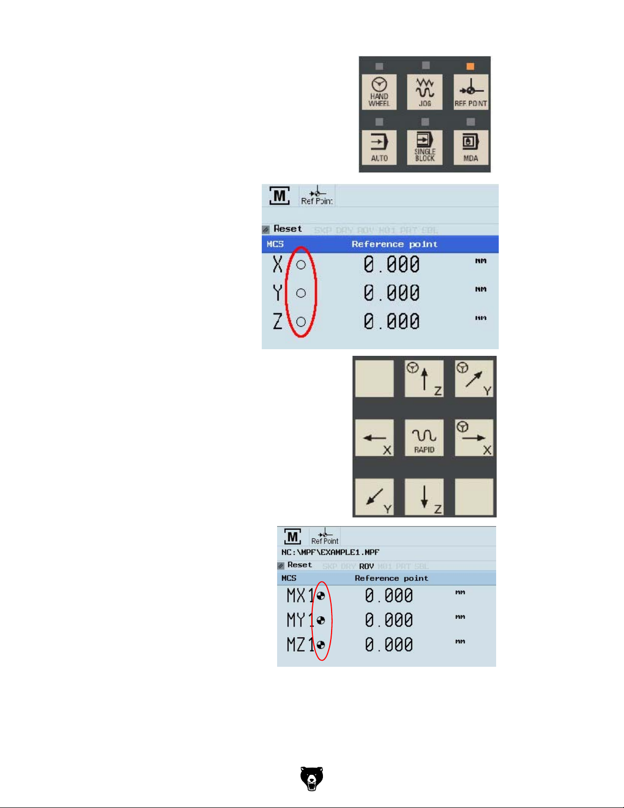
After switching on, the G0876 is in the mode reference
point approach area, the LED on the <REF POINT> button
lights.
As long as the axes are not referenced,
the symbol (circle) between the axis and
the corresponding value is displayed.
The axes are referenced with the
"axis traversing keys."
Make sure that the "feed override switch"
is not set to "zero".
+
Traverse each axis to the machine
zero point until the referenced symbol is shown on the respective axis.
Once the axis approaches the reference point, the referenced symbol must
shown next to the axis.
+
+
-56-
Model G0876 (Mfd. Since 12/22)
Page 59

After returning to the "JOG" mode, the axes can be moved
manually. Use the Increment button to specify the increment, or press the <JOG> button again to stop the increment again.
If possible, read the upcoming mes-
sages on the display, remove the
error messages, such as e.g. insuffi-
cient compressed air, ....
Default values for example should
apply for the feed rate in the "JOG"
mode, be entered on the side of the
standard values .
Press the button <OFFSET> to get
to the settings.
For the following working steps,
please proceed as described in
„Operation and programming“ of the
Siemens SINUMERIK 808D Operation instructions.
Model G0876 (Mfd. Since 12/22)
-57-
Page 60

6.5.3 Using the electronic handwheel
The electronic handwheel can always be used when
the CNC- machine is referenced,
the LED on the button <HANDWHEEL> lights up.
Press the button <HANDWHEEL> on the machine control panel to use the electronic handwheel.
Pos.
No.
1
4
5
1
3
2
3
2
4
5
WARNING!
A manual movement of axes with open door is not possible. The G0876 has
no acknowledgment button to allow movement of axes with open slide door.
The lock switch on the slide door may only be unlocked for maintenance and repair
work.
Meaning Description
Rotary switch
Rotary switch
Hand wheel Hand wheel for individual axes travel.
<EMERGENCY
STOP button>
Push button/
acknowledge-
ment button
Selector switch for individual axes con-
trol.
Selector switch for the feed speed (3
stages).
The EMERGENCY STOP push button
switches off the CNC- machine.
In the setting mode it is necessary to
actuate the acknowledgement button
in order to expressively allow the
movement of the individual axes.
-58-
Model G0876 (Mfd. Since 12/22)
Page 61

6.5.4 Insert tool
INFORMATION
Before you can run a CNC program, at least one tool must have been created and
measured in the tool memory.
Change over to the mode <JOG>.
Press the "Offset" key on the
machine control panel.
Press the "Tool list" softkey
For the following working steps,
please proceed as described in
„Operation and programming“ of
the Siemens SINUMERIK 808D
Operation instructions.
6.5.5 Manual tool change
ATTENTION!
Hold your tool if there is a tool inserted in the spindle.
Press the push button "Open/Close door" and open the sliding door.
Check that the LED on the push button <K11>lights up.
Press - if necessary - the push button <K11>. The manual tool change is
thereby enabled again.
Press the push button "manual tool change" to loosen or to clamp the tool.
K11
Img.6-3: Spindle head
Model G0876 (Mfd. Since 12/22)
Push button manual
Changing the tool
-59-
Page 62

6.5.6 Clamping the workpiece
ATTENTION!
The workpiece is always to be fixed by a machine vice, jaw chuck or by another
appropriate clamping tool such as for the clamping claws.
When setting and using already created programs observe the safety clearance in order
to avoid collisions with the selected clamping means.
WARNING!
Risk of injury caused by flying workpieces.
Clamp the workpiece in the machine
vice.
Make sure that the workpiece is firmly
clamped in the vise.
6.5.7 Manual tool change
ATTENTION!
Hold your tool if there is a tool inserted in the spindle.
Press the push button "Open/Close door" and open the sliding door.
Check that the LED on the push button <K11>lights up.
Press - if necessary - the push button <K11>. The manual tool change is
thereby enabled again.
Press the push button "manual tool change" to loosen or to clamp the tool.
Workpiece
Machine vice
Img.6-4: Clamping the workpiece
K11
Img.6-5: Spindle head
-60-
Push button manual
Changing the tool
Model G0876 (Mfd. Since 12/22)
Page 63

6.5.8 Turning off the CNC- machine
Push the EMERGENCY stop push button.
For a long-term standstill of the CNC machine, switch it off at the main switch.
"Disconnecting and securing the CNC machine“ on page 19
6.6 Operational modes
Manually controlled operation
The manually controlled operation is possible in the "JOG" and "MDA" operating modes. Refer
to chapter 5 "Manual mode" of the operating instructions of "SINUMERIK 808D".
Automatic mode
Refer to chapter 6 "Setup machine" of the operating instructions for "SINUMERIK 808D".
6.7 Programming
For further working steps please proceed as described in the operating instructions "Part programming, system, programming and cycles“ for SINUMERIK 808D.
Manual resp. part programming:
For this kind of programming, the programs must be created manually and entered in the control unit. The direct programming in the DIN-Code is a complex method which requires lots of
skills. Nowadays this task is mostly taken over by CAD/CAM systems which directly create an
operating program using a graphical user interface.
Automatic programming:
Construction data are transmitted (semi-) automatically to an executable program by means of
the CAD/CAM program (for instance a 3D-CAD program including downstream co-processor).
For this kind of programming, a 3D model is designed using a PC. The motion-sequence of the
machine is calculated by means of an operating sequence which is predefined by the user.
These programs access the tool data base which includes all tool parameters (speed, feed,
diameter, etc.). Due to this systematic program structure, the user is able to create a complete
program in a short period of time without having any knowledge of the individual program commands and their syntax.
DIN Code and ISO Code:
Use the procedure for switching or activating the programming language in the manual operation and programming of the "SINUMERIK 808D".
6.8 Starting the program
Adjusting the dosing for the coolant supply on the spindle head before starting the program.
Any change in the dosing must only be performed during the setup operation. The requirement
of coolant supply is switched on over your CNC- programs.
WARNING!
Never change the dosing of the cooling lubricant supply and never seize into the
machine when a program is running.
CAUTION!
Before startin
must be closed.
Completely close the separating protective equipment.
Change to "AUTO/MDA" mode.
g the program, the sl
iding door of the separating protective equipment
Model G0876 (Mfd. Since 12/22)
-61-
Page 64

For the following working steps, please proceed as described in „Operation and
programming“ of the Siemens "SINUMERIK 808D" Operation instructions.
V
6.9 Central lubrication system
The CNC machine is equipped with a central lubrication system.
The lubricating system is used to maintain an oil film on the slideways, the bearings, the ledges
and the ball screws and to reduce their wear.
In case of a failure or a fault in the central lubricating system, a stick-slip effect may occur. This
effect describes the jerky sliding of solid bodies moving opposite one another. For instance:
creaking doors and rattling windscreen wipers.
6.10 Data interfaces and current collection
When connecting data interfaces make sure that the data cable runs to the control unit interface
via the shortest possible distance. The cable routing can be conducted along the measuring
system lines. However the cable in the switch cabinet must never be routed near the drive units
of the NC axis or the frequency converter itself. Electromagnetic radiation causes errors during
data transfer (EMC problems).
The control is equipped with the following data interfaces.
X130 Ethernet port (RJ45 connector, only 808D ADVANCED)
USB connection
Connection for power supply
6.11 Selecting the speed
The correct speed is an important factor for milling. The speed determines the cutting speed by
which the cutting edges cut the material. By selecting the correct cutting speed, the service life
of the tool is increased and the working result is optimized.
The optimum cutting speed mainly depends on the material and on the material of the tool. With
tools (milling cutters) made of hard metal or ceramic insert it is possible to work with higher
speeds than with tools made of high-alloy high speed steel (HSS). You will achieve the optimal
cutting speed by selecting the correct rotation speed.
In order to determine the correct cutting speed for your tool and for the material to be cut you
may refer to the following standard values or a table reference book.
The required speed is calculated as follows:
------------
n
=
d
-1
n = speed in min
V = cutting speed in m/min (meter per minute)
d = tool diameter in m (Meter)
(revolutions per minute)
6.11.1 Standard values for cutting speeds
[ m/min ] with high-speed steel and hard metal in upcut milling.
Tool Steel Grey cast iron
Plain mill and side milling cutters [ m/min ]
Relieved form cutters [ m/min ] 15 - 24 10 - 20 150 - 250
-62-
10 - 25 10 - 22 150 - 350
Al
alloy
age-hardened
Model G0876 (Mfd. Since 12/22)
Page 65

Inserted -tooth cutter with SS [ m/min ] 15 - 30 12 - 25 200 - 300
Inserted-tooth cutter with HM [ m/min ] 100 - 200 30 - 100 300 - 400
The results are the following standard values for speeds in dependence of the
milling cutter diameter, cutter type and material.
Tool diameter
[ mm ] shell end mill and
plain milling cutter
35 91 - 227 91 - 200 1365 - 3185
40 80 - 199 80 - 175 1195 - 2790
45 71 - 177 71 - 156 1062 - 2470
50 64 - 159 64 - 140 955 - 2230
Tool diameter
[ mm ]
Form cutters
4 1194 - 1911 796 - 1592 11900 - 19000
5 955 - 1529 637 - 1274 9550 - 15900
6 796 - 1274 531 - 1062 7900 - 13200
8 597 - 955 398 - 796 5900 - 9900
10 478 - 764 318 - 637 4700 - 7900
12 398 - 637 265 - 531 3900 - 6600
Steel
10 - 25 m/min
Steel
15 - 24 m/min
Grey cast iron
10 - 22 m/min
Speed [ min-1 ]
Grey cast iron
10 - 20 m/min
Speed [ min-1 ]
Al alloy
age-hardened
150 - 350 m/min
Al alloy
cured 150 - 250
m/min
14 341 - 546 227 - 455 3400 - 5600
16 299 - 478 199 - 398 2900 - 4900
6.11.2 Standard values for speeds with HSS – Eco – twist drilling
Material
Steel, unalloyed,
up to 600 N/mm
Structural steel, alloyed,
quenched and subsequently
drawn, up to 900N/mm
Structural steel, alloyed,
quenched and subsequently
drawn, up to 1200 N/mm
Stainless steels up to 900 N/
2
e.g. X5CrNi1810
mm
1): Speed [ n ] in r/min
2): Feed [ f ] in mm/r
3): Cooling: E = Emulsion; oil = cutting oil
2
2
2
2345678910
1)
5600 3550 2800 2240 2000 1600 1400 1250 1120
n
2)
0.04 0.063 0.08 0.10 0.125 0.125 0.16 0.16 0.20
f
1)
3150 2000 1600 1250 1000 900 800 710 630
n
2)
0.032 0.05 0.063 0.08 0.10 0.10 0.125 0.125 0.16
f
1)
2500 1600 1250 1000 800 710 630 560 500
n
2)
0.032 0.04 0.05 0.063 0.08 0.10 0.10 0.125 0.125
f
1)
2000 1250 1000 800 630 500 500 400 400
n
2)
0.032 0.05 0.063 0.08 0.10 0.10 0.125 0.125 0.16
f
Drill diameter Cooling
3)
E
E/oil
Oil
Oil
Model G0876 (Mfd. Since 12/22)
-63-
Page 66

The above mentioned indications are standard values. In some cases it may be advanta-
geous to increase or decrease these values.
When drilling a cooling or lubricating agent should be used.
For stainless materials (e.g. VA – or NIRO steel sheets) do not center as the material would
compact and the drill bit will become rapidly blunt.
The workpieces need to be tensed in flexibly and stably (vice, screw clamp).
INFORMATION
Friction during the cutting process causes high temperatures at the cutting edge of the tool. The
tool should be cooled during the milling process. By cooling with an appropriate coolant lubricant you will achieve a better working result and longer durability of the tool.
INFORMATION
Use a water-soluble and non-pollutant emulsion as a cooling agent. This can be acquired from
authorised distributors.
Make sure that the cooling agent is properly retrieved. Respect the environment when disposing of any lubricants and coolants. Follow the manufacturer’s disposal instructions.
INFORMATION
The CNC milling machine is lacquered with a one-component paint. Observe this fact when
selecting your cooling lubricant.
-64-
Model G0876 (Mfd. Since 12/22)
Page 67
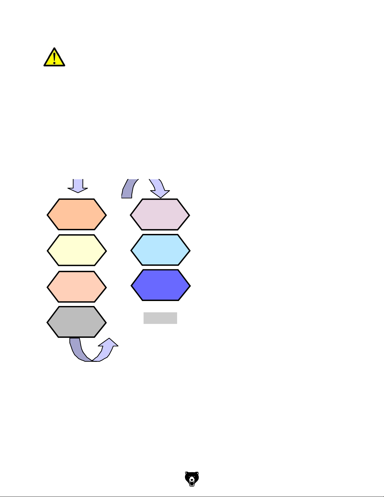
7 Brief instruction 808D Milling
Basic Theory
The 808D panel
processing unit (PPU)
is used to input data
to the CNC and to
navigate to operating
areas of the system.
Operating area
navigation
The 808D machine control panel
(MCP) is used to select the
machine operating mode :
JOG - MDA - AUTO
Mode navigation
Menu navigation
PPU
Function of
keyboard
MCP mode
Changing
Basic knowledge of programming for milling is required, before operating
of a machine !
The information provided in this brief insruction contains merely general descriptions or
characteristics of performance which in actual case of use do not always apply as
described or which may change as a result of further development of the products.
This brief instruction is not the replacement for Siemens 808D manuals and only serves
as a reference for quickly find already-known operations and functions.
7.1 Preparation
Description
This unit describes the 808D PPU and MCP functionality, the coordinate system of a
milling machine and how to enter passwords to access the system.
Content
PPU
PPU
Function of
Function of
keyboard
keyboard
MCP mode
MCP mode
Changing
Changing
MCP
MCP
Moving
Moving axis
axis
coordinate
coordinate
Passwords
Passwords
User
User
interface
interface
Machine
Machine
system
system
MCP
MCP
OEM
OEM
keys
Model G0876 (Mfd. Since 12/22)
End
-65-
Page 68

Basic Theory
PPU
Function of
keyboard
The 808D panel
processing unit (PPU)
is used to input data
to the CNC and to
navigate to operating
areas of the system.
Menu navigation
MCP mode
Changing
The 808D machine control panel
(MCP) is used to select the
machine operating mode :
JOG - MDA - AUTO
Operating area
navigation
Mode navigation
-66-
Model G0876 (Mfd. Since 12/22)
Page 69

Preparation
MCP
808D (PPU) has eight
vertical softkeys (abbr.
SKs) on the right of the
screen. These SKs can
be activated with the
corresponding button
(located on the right).
808D (PPU) has eight horizontal SKs on the bottom of the screen. These SKs can
be activated with the corresponding button (located below).
User
interface
Axis
feedrate
Act. val.
REL
Act. val.
Work(WCS)
Meas.
tool
Meas.
work.
Set
REL
Face
cutt.
Sett.T,S,M
Moving
axis
Axis movement
The 808D machine control panel (MCP)
is used to control manual operation of the
axis.
The machine can be moved with the
appropriate keys.
MCP
OEM
keys
The 808D machine control panel (MCP)
is used to control OEM machine
functions.
The machine functions can be activated
with the appropriate keys.
OEM keys
Model G0876 (Mfd. Since 12/22)
-67-
Page 70

User
interface
Axis
feedrate
808D (PPU) has eight
vertical softkeys (abbr.
SKs) on the right of the
screen. These SKs can
be activated with the
corresponding button
(located on the right).
Act. val.
REL
Act. val.
Work(WCS)
Meas.
work.
Meas.
tool
Set
REL
Face
cutt.
Sett.T,S,M
808D (PPU) has eight horizontal SKs on the bottom of the screen. These SKs can
be activated with the corresponding button (located below).
-68-
Model G0876 (Mfd. Since 12/22)
Page 71

Preparation
SEQUENCE
Machine
Step 1
Step 2
Passwords at the control are used to set the user’s right to
access the system. Tasks such as ”Basic Operating”,
“Advanced Operating” and commissioning functions all
depend on the passwords.
No password
Customer’s password
Manufacturer’s password
Customer’s password = CUSTOMER
Manufacturer’s password = SUNRISE
Machine operator
Advanced operator
OEM engineer
Changing
password
The service mode is opened with the
appropriate key combination.
In the service mode, the password
can be activated and deactivated.
Enter customer’s or manufacturer’s password
Change customer’s or manufacturer’s password
Delete customer’s or manufacturer’s password
Usually the machine, operator does not need to change the
password.
End
+
Passwords
Set
password
Change
password
Delete
password
Set
password
Change
password
Delete
password
coordinate
system
The Sinumerik 808D uses a
coordinate system which is
derived from the DIN 66217
standard.
The system is an international
standard and ensures
compatibility between machines
and coordinate programming.
The primary function of the
coordinate system is to ensure
that the tool length and tool
radius are calculated correctly in
the respective axis.
Model G0876 (Mfd. Since 12/22)
-69-
Page 72

SEQUENCE
Passwords
Passwords at the control are used to set the user’s right to
access the system. Tasks such as ”Basic Operating”,
“Advanced Operating” and commissioning functions all
depend on the passwords.
No password
Customer’s password
Manufacturer’s password
Customer’s password = CUSTOMER
Changing
Manufacturer’s password = SUNRISE
password
Step 1
Usually the machine, operator does not need to change the
password.
The service mode is opened with the
appropriate key combination.
In the service mode, the password
can be activated and deactivated.
Step 2
Machine operator
Advanced operator
OEM engineer
+
Set
password
Change
password
Delete
password
Set
password
Change
password
Delete
password
End
Enter customer’s or manufacturer’s password
Change customer’s or manufacturer’s password
Delete customer’s or manufacturer’s password
-70 -
Model G0876 (Mfd. Since 12/22)
Page 73

Switch On and Referencing
7.2 Switch On and Referencing
SEQUENCE
Please note the explicit switching on rules as specified by the
machine manufacturer.
Turn on the main switch of the machine.
Make sure you perform the following operation!
Step 1
Step 2
End
Switch on
the machine
PPU
Function of
keyboard
Switch on
the
machine
Release all the EMERGENCY STOP
buttons on the machine!
Description
This unit describes how to switch the machine on and reference it.
Content
Switch on
Switch on
PPU
the
the machine
Function of
machine
keyboard
MCP mode
Reference
Changing
the
machine
End
Model G0876 (Mfd. Since 12/22)
-71-
Page 74
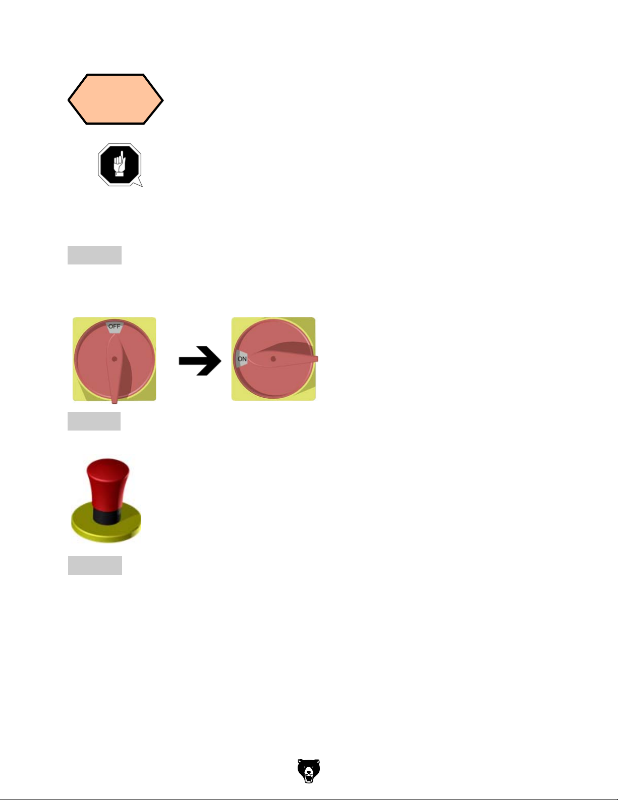
SEQUENCE
Switch on
Switch on
PPU
the machine
the
Function of
machine
keyboard
Please note the explicit switching on rules as specified by the
machine manufacturer.
Turn on the main switch of the machine.
Make sure you perform the following operation!
Step 1
Step 2
Release all the EMERGENCY STOP
buttons on the machine!
-72-
End
Model G0876 (Mfd. Since 12/22)
Page 75
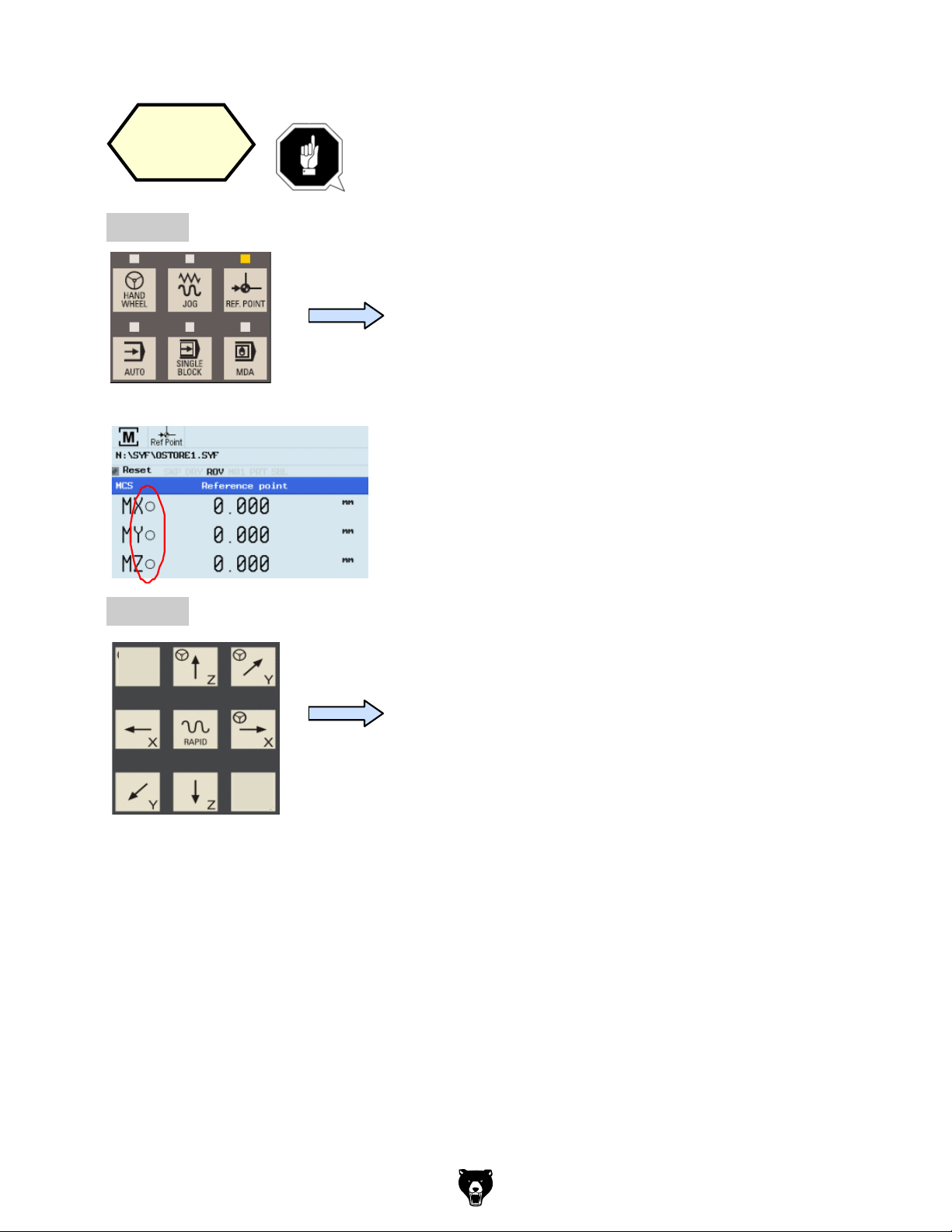
Switch On and Referencing
SEQUENCE
MCP mode
After completing the referencing procedure for
all axes, the referenced symbol is displayed
next to the axis identifier.
After returning to JOG mode, use the axis
traversing keys to move the machine manually.
The machine can now be operated in JOG
mode.
During normal operation (JOG),the referenced
symbol is not shown on the screen.
Step 3
End
Reference
Changing
machine
Step 1
the
If your machine is configure with ABS encoder, you
do not need to reference the axis of the machine.
If your machine is fitted with INC encoder, After
power on, the machine must first be referenced!
Step 2
After power on, the machine will be in the
reference point approach mode (default).
If the axis is not referenced, the nonreferenced symbol (circle) is displayed
between the axis identifier and the value.
The axes are referenced with the
corresponding axis traversing keys.
The traversing direction and keys are
specified by the machine manufacturer.
Model G0876 (Mfd. Since 12/22)
-73 -
Page 76

Switch On and Referencing
After completing the referencing procedure for
all axes, the referenced symbol is displayed
next to the axis identifier.
Step 3
End
After returning to JOG mode, use the axis
traversing keys to move the machine manually.
The machine can now be operated in JOG
mode.
During normal operation (JOG),the referenced
symbol is not shown on the screen.
-74 -
Model G0876 (Mfd. Since 12/22)
Page 77

Tool Setup
7.3 Tool Setup
SEQUENCE
Please make sure the system is in JOG mode.
Press “Offset” on the PPU.
Press the “Tool list” SK on the PPU.
A tool must have been created and measured
before executing the program.
Step 1
Create
tool
Tool
list
Description
This unit describes how to create and set up tools.
Content
Create
tool
Create tool
edge
Load tool into
active
position
Move
machine with
handwheel
Start
spindle
Measure
tool
Machine
JOG
coordinate
spindle
system
User
Execute M
interface
function
End
Model G0876 (Mfd. Since 12/22)
-75-
Page 78

SEQUENCE
Create
tool
A tool must have been created and measured
before executing the program.
Step 1
Please make sure the system is in JOG mode.
Press “Offset” on the PPU.
Press the “Tool list” SK on the PPU.
Tool
list
-76-
Model G0876 (Mfd. Since 12/22)
Page 79

Tool Setup
SEQUENCE
Step 2
A tool must have been created and selected
before creating a tool edge!
Use “D” code to specify the tool edge. The system activates tool edge
no. 1 per default at the start.
Press the “Offset” key on the PPU.
Press the “Tool list” SK on the PPU.
Or
Use direction keys to select the tool which
needs to add a tool edge.
Press the “Edges” SK on the PPU.
Press the “New edge” SK on the PPU.
Step 1
Create
tool edge
User
data
Work
offset
R
var.
Set
data
Tool
wear
Tool
list
Lenght1
Radius
Geometry
Tool list
Type
Back
New
edge
Reset
edge
Delete
edge
Tool
list
Edges
New
edge
The range of tool numbers which can be created
by this system is 1 ~32000.
The machine can be loaded with a maximum of
64 tools / 128 tool edges.
Press the “New tool” SK on the PPU.
Select the type of tool required.
Tool list
Tool No.:
Enter the ”Radius” of the milling tool.
milling tool
Press the “OK” SK on the PPU.
Enter “1” at “Tool No.”
New milling tool
Identifier
New
tool
Milling
tool
Drilling
tool
Tapping
tool
Ball end
mil. tool
Press the “Input” button on the PPU.
Model G0876 (Mfd. Since 12/22)
-77-
Page 80

Create
tool edge
A tool must have been created and selected
before creating a tool edge!
Step 1
Use “D” code to specify the tool edge. The system activates tool edge
no. 1 per default at the start.
Press the “Offset” key on the PPU.
Press the “Tool list” SK on the PPU.
Use direction keys to select the tool which
needs to add a tool edge.
Tool list
Type
Lenght1
Geometry
Radius
New
edge
Reset
edge
Delete
edge
Tool
list
Or
Tool
list
Tool
wear
Work
offset
Press the “Edges” SK on the PPU.
Press the “New edge” SK on the PPU.
R
var.
Set
data
Back
User
data
Edges
New
edge
-78 -
Model G0876 (Mfd. Since 12/22)
Page 81
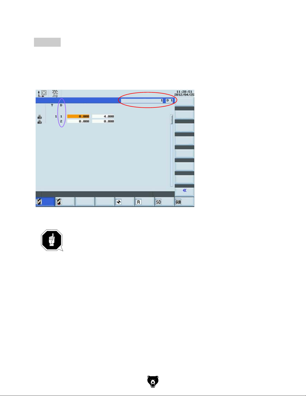
Tool Setup
SEQUENCE
The red circle shows the actual active tool
many tool edges have been created and the related data for each tool edge.
Step 2
Load tool into
Spindle
A tool must have been created in the system
before it can be loaded into the active position.
Press the “Machine” key on the PPU
Press “CYCLE START” on the MCP
Press the “Back” SK on the PPU
Press the “JOG” key on the MCP
Press the “T.S.M” SK on the PPU
Enter tool number “1” in “T”
T,S,M
Tool change
Spindle speed
Spindle direction
Activate zerooffset
Other M function
rpm
Back
Sett.
Meas.
tool
Meas.
work.
Set
rel
Face
cutt.
Press ´CYCLE START´
to activate above functions.
back
A new tool edge can be added in this way and different lengths and radii can be
entered as required.
and tool edge,the purple circle shows how
Tool list
Type
Lenght1
Geometry
Radius
Active tool no
Tool
list
Tool
wear
Work
offset
R
var.
Sett.
data
A maximum of nine tool edges can be created for each tool!
Different tool lengths and radii can be saved in different tool edges as
required.
Please select the right tool edge for machining according to
requirement!
New
edge
Reset
edge
Delete
edge
Back
User
data
Model G0876 (Mfd. Since 12/22)
-79 -
Page 82

Load tool into
Spindle
T,S,M
Tool change
Spindle speed
Spindle direction
Activate zerooffset
Other M function
Press ´CYCLE START´
Set
rel
A tool must have been created in the system
before it can be loaded into the active position.
Press the “Machine” key on the PPU
Press the “JOG” key on the MCP
Press the “T.S.M” SK on the PPU
Enter tool number “1” in “T”
rpm
to activate above functions.
Meas.
work.
Meas.
tool
Face
cutt.
Back
Sett.
Press “CYCLE START” on the MCP
Press the “Back” SK on the PPU
back
-80-
Model G0876 (Mfd. Since 12/22)
Page 83

Tool Setup
SEQUENCE
The tool are usually loaded manually into the spindle.
The tool will be automatically
A handwheel can control the axis motion instead of the “JOG” button.
Move
Select the required override increment
according to the buttons on the right(this
selection fits all axes)
The handwheel increment is “0.001 mm”
The handwheel increment is “0.010 mm”
The handwheel increment is “0.100 mm”
The selected axis can now be moved with the handwheel.
Press “JOG” on MCP to end the function of
“Handwheel”.
Notes: If set the MD14512[16]=80, the system will deactivate the function of
MCP for selecting the axis of handwheel, the user will have to activate
“Handwheel” function with PPU softkey.
Select the required axis on
the right of the PPU; the
selected axis is shown with a
√
Handwheel
Handwheel
Axis
Number
machine with
handwheel
loaded into the spindle with an automatic tool changer.
Make sure there is no obstruction when moving
the tool to avoid a crash.
Press the “Machine” key on the PPU
Press the “Handwheel” key on the MCP
Select the axis you want to move with the
appropriate keys. on the MCP
Under “WCS” or
“MCS” state, a handwheel will be shown beside
the axis symbols, showing the axis is chosen,
and can be controlled with a handwheel.
Model G0876 (Mfd. Since 12/22)
-81-
Page 84

Select the required override increment
according to the buttons on the right(this
selection fits all axes)
The handwheel increment is “0.001 mm”
The handwheel increment is “0.010 mm”
The handwheel increment is “0.100 mm”
The selected axis can now be moved with the handwheel.
Press “JOG” on MCP to end the function of
“Handwheel”.
Notes: If set the MD14512[16]=80, the system will deactivate the function of
MCP for selecting the axis of handwheel, the user will have to activate
“Handwheel” function with PPU softkey.
Handwheel
Axis
Number
Handwheel
Select the required axis on
the right of the PPU; the
selected axis is shown with a
√
-82-
Model G0876 (Mfd. Since 12/22)
Page 85

Tool Setup
SEQUENCE
Start the spindle before adjusting tools as follows:
Press “Reset” on the MCP to stop the spindle
rotation
Press the “Back” SK on the PPU
A tool must have been created and loaded
before it can be measured!
Press the “Machine” key on the PPU
Press the “JOG” key on the MCP
Press the “Meas. tool” SK on the PPU
Press the “Measure manual” SK on the PPU
Measure length
OPTIMUM
Step 1
Measure
tool
Meas-
tool
Measure
manual
back
Select “M3” using the “Select” key on the PPU
Start
spindle
A tool must have been loaded and rotated to the
position.
Press the “Machine” key on the PPU
Press the “JOG” key on the MCP
Press the “T.S.M” SK on the PPU
Enter “500” at “Spindle speed”
T,S,M
Tool change
Spindle speed
Spindle direction
Activate zerooffset
Other M function
Press ´CYCLE START´
Set
rel
rpm
to activate above functions.
Meas.
work.
Press the “CYCLE START” key on the MCP
Meas.
tool
Face
cutt.
Back
Sett.
Model G0876 (Mfd. Since 12/22)
-83-
Page 86

Press “Reset” on the MCP to stop the spindle
rotation
OPTIMUM
Press the “Back” SK on the PPU
Measure
tool
A tool must have been created and loaded
before it can be measured!
Step 1
Measure length
Press the “Machine” key on the PPU
Press the “JOG” key on the MCP
Press the “Meas. tool” SK on the PPU
Press the “Measure manual” SK on the PPU
back
Meastool
Measure
manual
-84-
Model G0876 (Mfd. Since 12/22)
Page 87

Tool Setup
SEQUENCE
Press the axis keys on the MCP to move
Use “SELECT” key to set the reference point as
“workpiece” (In real measurement, the reference
point can be set as either “workpiece” or “ fixed
point” if required.)
Enter “0” for “Z0”
(If the setting block is used, then the value would
be thickness a)
Press the “Set length” SK on the PPU
The measured tool length is now shown in “Length (L)”. This value is also saved in the
length value column of the corresponding tool list at the same time.
Measure diameter
Press the “Diameter” SK on the PPU
Step 2
Set
length
Diameter
Tool measurement maual
Use workpiece
Ref. point
Workpiece
Length (L)
Set
REL
Meas.
work.
Meas.
tool
Face
cutt.
Sett.
Back
Set
length
the tool to the set position above the
workpiece.
Note: The following text describes the required
settings in the workpiece coordinate system
“X / Y / Z” zero points as:“X0” / “Y0” / “Z0”
Press the “Handwheel” key on the MPC
and position the tool at location Z0 or a of
the workpiece.
Move directly to zero point
or
a
Use a setting block.
Model G0876 (Mfd. Since 12/22)
-85-
Page 88

Use “SELECT” key to set the reference point as
“workpiece” (In real measurement, the reference
point can be set as either “workpiece” or “ fixed
point” if required.)
Enter “0” for “Z0”
(If the setting block is used, then the value would
be thickness a)
Tool measurement maual
Ref. point
Length (L)
Set
REL
Meas.
work.
Meas.
tool
Press the “Set length” SK on the PPU
The measured tool length is now shown in “Length (L)”. This value is also saved in the
length value column of the corresponding tool list at the same time.
Step 2
Measure diameter
Press the “Diameter” SK on the PPU
Use workpiece
Workpiece
Face
cutt.
Set
length
Back
Sett.
Set
length
Diameter
-86-
Model G0876 (Mfd. Since 12/22)
Page 89

Tool Setup
SEQUENCE
Press the axis keys on the MCP to move
Enter “0” at “X0”
Enter “0” at “Y0”
(This is the value of the width of a setting block if it
is used.Select one of X0/Y0 according to
requirement.)
Press the ”Set diameter” SK on the PPU
Press the “Back” SK on the PPU
Set
diameter
Tool measurement manual
Workpiece edge
Diameter
Meas.
tool
Meas.
work.
Set
rel
Face
cutt.
Set
diameter
Back
Sett.
back
the tool to the set position.
Press the “Handwheel” key on the MCP
and position the tool at the location
X0 or a of the workpiece.
Move directly to zero point
or
Use a setting block.
a
Model G0876 (Mfd. Since 12/22)
-87-
Page 90
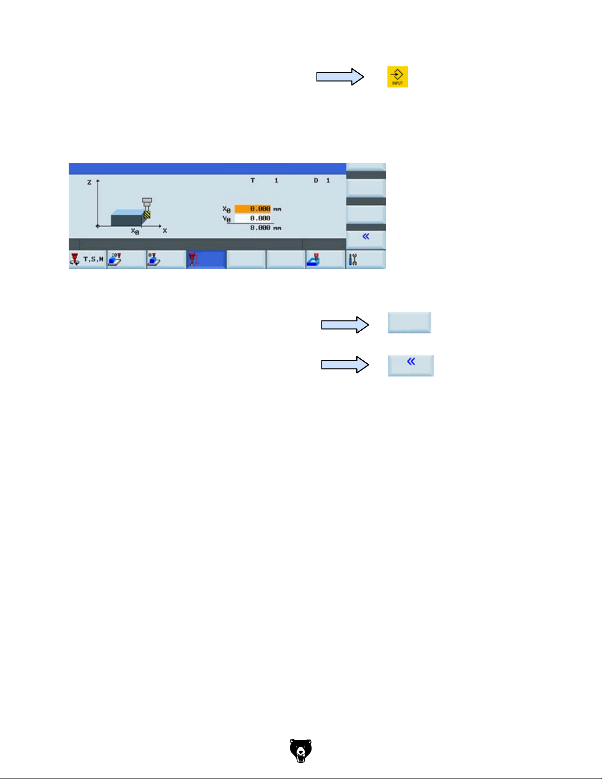
Enter “0” at “X0”
Enter “0” at “Y0”
(This is the value of the width of a setting block if it
is used.Select one of X0/Y0 according to
requirement.)
Tool measurement manual
Set
rel
Press the ”Set diameter” SK on the PPU
Press the “Back” SK on the PPU
Workpiece edge
Diameter
Meas.
work.
Meas.
tool
Face
cutt.
Set
diameter
Back
Sett.
Set
diameter
back
-88-
Model G0876 (Mfd. Since 12/22)
Page 91
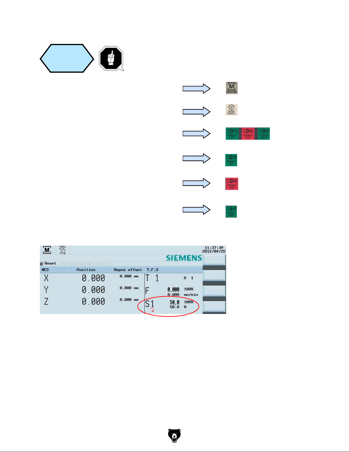
Please make sure all the machine axes are in
safe positions before executing the M function!
Press the “Machine” key on the PPU
Press the “T.S.M” SK on the PPU.
Use the direction key to move the highlighted
cursor to “Other M function” and enter “8”. This
will start the coolant.
Press “CYCLE START” on the MCP.
The coolant function button on MCP is active.
Press the “Reset” key on the MCP to stop the
coolant function.
Press the “Back” SK on the PPU.
User
interface
Execute M
function
T,S,M
Tool change
Spindle speed
Spindle direction
Activate zerooffset
Other M function
rpm
Back
Sett.
Meas.
tool
Meas.
work.
Set
rel
Face
cutt.
Press ´CYCLE START´
to activate above functions.
8
SEQUENCE
Machine
JOG
coordinate
spindle
system
A tool must be loaded to the spindle.
Press the “Machine” key on the PPU
Press the “JOG” key on the MCP
Press the spindle direction key on the MCP to
start/stop the spindle.
Press “Spindle left” on the MCP to start the
spindle in the counter-clockwise direction.
Press “Spindle stop” on the MCP to stop the
spindle.
Press “Spindle right” on the MCP to start the
spindle in the clockwise direction.
Model G0876 (Mfd. Since 12/22)
-89-
Page 92

Tool Setup
User
Execute M
interface
function
Please make sure all the machine axes are in
safe positions before executing the M function!
Press the “Machine” key on the PPU
Press the “T.S.M” SK on the PPU.
Use the direction key to move the highlighted
cursor to “Other M function” and enter “8”. This
will start the coolant.
T,S,M
Tool change
Spindle speed
Spindle direction
Activate zerooffset
Other M function
Press ´CYCLE START´
Set
rel
8
rpm
to activate above functions.
Meas.
work.
Meas.
tool
Press “CYCLE START” on the MCP.
The coolant function button on MCP is active.
Press the “Reset” key on the MCP to stop the
coolant function.
Back
Face
cutt.
Sett.
-90-
Press the “Back” SK on the PPU.
Model G0876 (Mfd. Since 12/22)
Page 93

Workpiece Setup
7.4 Workpiece Setup
Description
SEQUENCE
A tool must have been loaded into the spindle.
Press the “Machine” key on the PPU
Press the “JOG” key on the MCP
Before measuring, the spindle can be started as follows:
Press the “T.S.M” SK on the PPU.
Enter “500” at “Spindle speed”
Select “M3” using the “Select” key on the PPU
Press the “CYCLE START” key on the MCP
Manual
start
spindle
T,S,M
T,S,M
Tool change
Spindle speed
Spindle direction
Activate zerooffset
Other M function
rpm
Back
Sett.
Meas.
tool
Meas.
work.
Set
rel
Face
cutt.
Press ´CYCLE START´
to activate above functions.
500
M3
This unit describes how to set the workpiece offset and test the tool results.
Content
Manual
start
spindle
Create
workpiece
offset
Test tool
offset results
End
Model G0876 (Mfd. Since 12/22)
-91-
Page 94

SEQUENCE
Before measuring, the spindle can be started as follows:
T,S,M
Manual
start
spindle
A tool must have been loaded into the spindle.
Press the “Machine” key on the PPU
Press the “JOG” key on the MCP
Press the “T.S.M” SK on the PPU.
Enter “500” at “Spindle speed”
Select “M3” using the “Select” key on the PPU
T,S,M
Tool change
Spindle speed
Spindle direction
Activate zerooffset
Other M function
Press ´CYCLE START´
Set
rel
500
M3
rpm
to activate above functions.
Meas.
work.
Meas.
tool
Face
cutt.
Back
Sett.
-92-
Press the “CYCLE START” key on the MCP
Model G0876 (Mfd. Since 12/22)
Page 95

Workpiece Setup
SEQUENCE
A tool must have be created and measured
before it can be used to set the workpiece
offset.
Make sure the active tool is the measured tool!
As the following red frame shows, 808D provides the user with three methods of using
tools to simplify the operating process.
Press the “Machine” key on the PPU.
Press the “JOG” key on the MCP.
Press the “Meas. work.” SK on the PPU.
Create
workpiece
offset
Meas.
work.
T,S,M
Set
rel
Meas.
work.
Meas.
tool
Face
cutt.
Back
Sett.
Press “Reset” on the MCP to stop the spindle
Press the “Back” SK on the PPU
rotation
Model G0876 (Mfd. Since 12/22)
-93-
Page 96

Create
workpiece
offset
A tool must have be created and measured
before it can be used to set the workpiece
offset.
Make sure the active tool is the measured tool!
Press the “Machine” key on the PPU.
Press the “JOG” key on the MCP.
Press the “Meas. work.” SK on the PPU.
Meas.
work.
As the following red frame shows, 808D provides the user with three methods of using
tools to simplify the operating process.
Back
T,S,M
Set
rel
Meas.
work.
Meas.
tool
Face
cutt.
Sett.
-94-
Model G0876 (Mfd. Since 12/22)
Page 97

Workpiece Setup
SEQUENCE
This method is normally for setting the zero point of the workpiece at the
Using a tool that has a measured “Tool leng
position on the workpiece. Using either JOG or Handwheel, scratch an edge and then
calculate the zero point of the workpiece.
The process of setting the “X” zero point (“X0”) is described below.
Method 1
Press the “Handwheel” key
on the MCP to position the
tool at the X0 edge of the
workpiece.
Select “Save in” Offset “G54” (or other
offset).
Select “Measuring direction” as “-”.
(This value should be chosen according to
realities)
Set “Distance” as “0”.
Press the “Set WO” SK on the PPU.
“Step 2” must be repeated for the setting of Y and Z zero points.
If you change the tool because of wear/damage during the machining process, you
must remeasure the length of the tool.
Set
WO
edge of the workpiece.
th & radius”, move the tool to a known
Press the corresponding SK of the first icon on
the right-hand side of the PPU.
Press the appropriate SK to select the feed axis
which needs to be set up.
Press the axis traverse keys to move the tool to
the required setting position in the X axis.
Model G0876 (Mfd. Since 12/22)
-95-
Page 98

Press the “Handwheel” key
on the MCP to position the
tool at the X0 edge of the
workpiece.
Select “Save in” Offset “G54” (or other
offset).
Select “Measuring direction” as “-”.
(This value should be chosen according to
realities)
Set “Distance” as “0”.
Press the “Set WO” SK on the PPU.
Set
WO
“Step 2” must be repeated for the setting of Y and Z zero points.
If you change the tool because of wear/damage during the machining process, you
must remeasure the length of the tool.
-96-
Model G0876 (Mfd. Since 12/22)
Page 99

Workpiece Setup
SEQUENCE
This method is normally used for setting the workpiece zero point at the
Using tools with a measured “length and radius
rectangular workpiece. Using either JOG
calculate the zero point of the workpiece.
This method is normally used for setting the zero points at the center
point of a circular workpiece.
Using tools with a measured “length and radius”, move them to the three edges of the
circular workpiece. Using either JOG or Handwheel, scratch an edge and then calculate
the zero point of the workpiece.
Press the corresponding SK of the third icon on
the right-hand side of the PPU.
Press the ”Save P1” SK on the PPU to save the
coordinate axis of the 1st position in the system.
Observing the figure on the PPU, move the coordinate axis following the orange arrow
to move the tool to the specified position and scratch the edge of the workpiece.
Repeat the process for positions 2 and 3.
(When the setting is complete, the buttons will be
shown in blue.)
Press the “Set WO” SK on the PPU.
You have then finished
setting the zero point of
the workpiece as the
center point of the circular
workpiece.
Method 3
Save P1
Set
WO
Save P1
Save P2
Save P3
Workpiece measurement, center of circle
Work offset
Offset
Compensation data have been activated!
T,S,M
Set
rel
Meas.
work.
Meas.
tool
G54
Face
cutt.
Back
Sett.
Set
WO
Method 2
center point of a rectangular workpiece.
”, move them to the four edges of the
or Handwheel, scratch an edge and then
Press the corresponding SK of the second icon on
the right-hand side of the PPU.
Observing the figure on the PPU, move the coordinate axis following the orange arrow
to move the tool to the specified position and scratch the edge of the workpiece.
Save P1
Press the ”Save P1” SK on the PPU to save the
coordinate axis of the 1st position in the system.
Repeat the process for positions 2, 3 and 4.
(When the setting is complete, the buttons will be
shown in blue.)
Save P1
Save P2
Save P3
Save P4
Press the “Set WO” SK on the PPU.
You have then finished
Set
WO
setting the zero point of
Workpiece measurement, center of rectangle
Work offset
Offset
Compensation data have been activated!
T,S,M
Set
rel
Meas.
work.
Meas.
tool
G54
Face
cutt.
Save P4
Set
WO
Back
the workpiece as the
center point of the
rectangular workpiece.
Sett.
Model G0876 (Mfd. Since 12/22)
-97-
Page 100
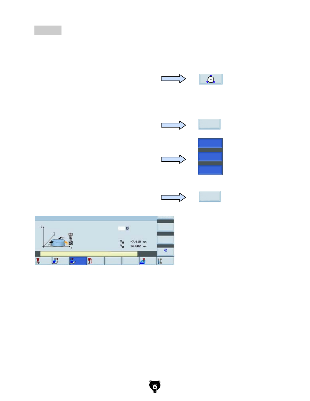
This method is normally used for setting the zero points at the center
Method 3
point of a circular workpiece.
Using tools with a measured “length and radius”, move them to the three edges of the
circular workpiece. Using either JOG or Handwheel, scratch an edge and then calculate
the zero point of the workpiece.
Press the corresponding SK of the third icon on
the right-hand side of the PPU.
Observing the figure on the PPU, move the coordinate axis following the orange arrow
to move the tool to the specified position and scratch the edge of the workpiece.
Press the ”Save P1” SK on the PPU to save the
coordinate axis of the 1st position in the system.
Repeat the process for positions 2 and 3.
(When the setting is complete, the buttons will be
shown in blue.)
Press the “Set WO” SK on the PPU.
You have then finished
Workpiece measurement, center of circle
Work offset
Offset
Compensation data have been activated!
T,S,M
Set
rel
Meas.
work.
Meas.
tool
G54
Face
cutt.
Set
WO
Back
setting the zero point of
the workpiece as the
center point of the circular
workpiece.
Sett.
Save P1
Save P1
Save P2
Save P3
Set
WO
-98-
Model G0876 (Mfd. Since 12/22)
 Loading...