

Page 1

MODEL G0863
GRIZZLY GROWLER
CYCLONE SEPARATOR
INSTRUCTIONS
For questions or help with this product contact Tech Support at (570) 546-9663 or techsupport@grizzly.com
Introduction
The Grizzly Growler creates a cyclone of incoming air that separates heavy wood chips and large
dust particles, increasing the performance of your
single-stage dust collector, and resulting in less
suction loss from dirty or clogged filters.
Inventory
Description Qty
A. Collection Drum .......................................... 1
B. Cyclone Funnel w/Band Clamp .................. 1
C. Intake Barrel ............................................... 1
D. Collection Drum Lid ................................... 1
1
E. Vacuum Hose 1
⁄2 " x 67" ............................ 1
F. Inlet Adapter 6" x 4" x 2 .............................. 1
G. Vacuum Ring .............................................. 1
H. Universal Reducer ...................................... 1
I. Intake Adapter 7" x 6" ................................ 1
J. Phillips Head Screws M4-.7 x 8 (Latches) . . 8
1
K. Flange Bolts
⁄4" -20 x 1⁄2 " (Funnel) .............. 6
L. Casters, 2" Swivel Ball .............................. 4
M. Lock Nuts M4-.7 (Latches) ......................... 8
1
N. Flange Nuts
⁄4" - 2 0 (Funnel) ....................... 6
O. Collection Drum Latches ............................ 2
1
P. Acorn Nuts
Q. Flange Screws #10-24 x
⁄4" -20 (Handle) ........................ 2
3
⁄8"
—Intake Adapter ........................................ 1
—Inlet Adapter ........................................... 1
1
R. Phillips Hd. Screws
⁄4" -20 x 5⁄8" (Handle) ... 2
S. Open-End Wrench 10/12mm ...................... 1
T. Handle ........................................................ 1
1
U. Hose Clamps 1
⁄2 " ...................................... 2
V. Plastic Bag 30" X 41" (not shown) .............. 1
Specifications
Recommended Horsepower Range ..... 1.5– 3 HP
Airflow Range ............................. 750–2300 CFM
Outlet Size .................................................... 7 in.
Inlet Size ....................................................... 6 in.
Max. Material Collection Capacity ............20 Gal.
A
D
F
H
G
Figure 1. Inventory—components.
JM
J
N
P
Q
K
S
L
T
Figure 2. Inventory—hardware.
B
C
E
I
O
R
U
COPYRIGHT © JANUARY, 2019 BY GRIZZLY INDUSTRIAL, INC.
NO PORTION OF THIS MANUAL MAY BE REPRODUCED IN ANY SHAPE
OR FORM WITHOUT THE WRITTEN APPROVAL OF GRIZZLY INDUSTRIAL, INC.
(FOR MODELS MFD. SINCE 10/18) #MN20050 PRINTED IN TAIWAN
V1.01.19
Page 2
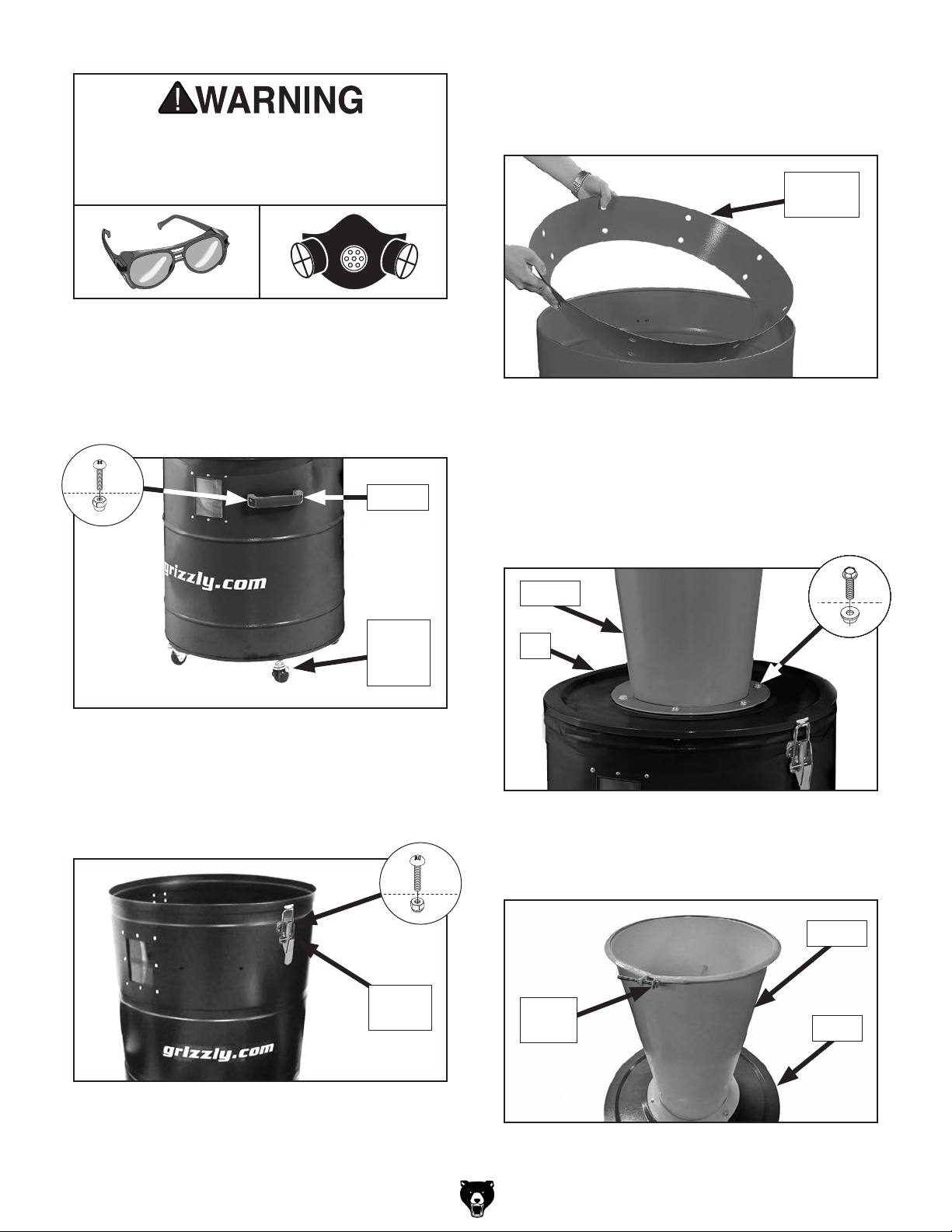
To reduce risk of eye injury from flying
chips or lung damage from breathing dust,
always wear safety glasses and a respirator
when operating this machine.
Assembly
1. Install (4) caster wheels on bottom of collec-
tion drum. Then attach handle to drum with
1
⁄4" -20 x 5⁄8" Phillips head screws and (2)
(2)
1
⁄4" -20 acorn nuts (see Figure 3).
3. Place vacuum ring inside collection drum with
smaller side of ring facing down, as shown in
Figure 5.
Vacuum
Ring
Figure 5. Placing vacuum ring inside collection
drum.
x 2
Handle
Caster
Wheel
(1 of 4)
Figure 3. Handle and caster wheels installed on
collection drum.
2. Install (2) collection drum latches with (8)
M4-.7 x 8 Phillips head screws and (8) M4-.7
lock nuts (see Figure 4).
x 4
4. Attach cyclone funnel to collection drum lid
1
using (6)
1
⁄4" -20 flange nuts. Then set funnel and lid on
⁄4" -20 x 1⁄2 " flange bolts and (6)
collection drum and secure with latches (see
Figure 6).
Funnel
x 6
Lid
Figure 6. Funnel attached to collection drum lid.
5. Loosen band clamp at top of cyclone funnel
(see Figure 7) to reveal metal lip.
Figure 4. Latches installed on collection drum.
-2-
Latch
(1 of 2)
Funnel
Band
Clamp
Drum
Figure 7. Location of band clamp at top of
cyclone funnel.
G0863 Grizzly Growler (Mfd. Since 10/18)
Page 3

6. Place intake barrel on top of funnel (see
Figure 8), then position clamp so band cap-
tures lip at top of funnel and lip at bottom of
barrel. Tighten clamp to secure.
9. Install intake adapter (see Figure 11) on
3
intake barrel with #10-24 x
⁄8" flange screw.
Adapter
Intake
Barrel
Band
Clamp
Funnel
Figure 8. Intake barrel attached to funnel.
7. Place hose clamps over ends of vacuum hose,
then attach one end of vacuum hose to intake
barrel (see Figure 9) and other end to collection
drum. Tighten clamps to secure hose.
Intake
Barrel Port
Intake
Barrel
Flange
Screw
Figure 11. Installing adapter on intake barrel.
10. Insert plastic dust bag inside collection drum,
and fold excess length of bag over top of
drum.
11. Route a dust hose from dust collector inlet to
Grizzly Growler intake (see Figure 12). Then
route a dust hose from Growler inlet to machine
dust port. Secure both hoses with clamps.
Intake
Collection
Drum Port
Figure 9. Vacuum hose attached to collection
drum and intake barrel.
Install inlet adapter on dust port and secure
8.
with #10-24 x
3
⁄8" flange screw (see Figure 10).
Flange Screw
Inlet
Adapter
Figure 10. Installing inlet adapter on dust port.
Inlet
To Machine
Dust Port
Dust Collector Inlet
Figure 12. Example of Grizzly Growler properly
connected to a dust collector.
Maintenance
Dispose of the collection drum bag when 3⁄4 full,
as seen in the drum window.
IMPORTANT: To contain wood dust and minimize
risk of exposure, firmly tie bag closed.
If bag gets overfilled, dust will be sucked into the
intake barrel and passed through to the dust collector filter. Check the drum window regularly to
prevent excessive dust buildup in collection drum.
G0863 Grizzly Growler (Mfd. Since 10/18)
-3-
Page 4

5
G0863 Parts Breakdown & List
Please Note: We do our best to stock replacement parts whenever possible, but we cannot guarantee that all parts shown here
28
17
19
24
34
18
16
22
33
31
2
35
43
23
42
21
1
30
30
REF PART # DESCRIPTION
1 P0863001 COLLECTION DRUM
2 P0863002 COLLECTION DRUM LID
3 P0863003 CYCLONE FUNNEL
6
4
23
29
20
13
7
4 P0863004 INTAKE BARREL
5 P0863005 INTAKE ADAPTER 7" X 6"
6 P0863006 HOSE CLAMP 1-1/2"
7 P0863007 FLANGE BOLT 1/4-20 X 1/2
8 P0863008 HANDLE
9 P0863009 PHLP HD SCR 1/4-20 X 5/8
10 P0863010 ACORN NUT 1/4-20
11 P0863011 CASTER, 2" SWIVEL BALL
12 P0863012 HEX NUT 5/16-18
13 P0863013 BAND CLAMP
14 P0863014 LOCK NUT M4-.7
3
grizzly.com
MODEL G0863
GRIZZLY GROWLER
CYCLONE SEPARATOR
Specifications
WARNING!
Horsepower Range: 1.5–3 HP
To reduce risk of serious injury when using this machine:
Airflow: 750–2300 CFM @ 2.3"-3.2" SP
1. Read and understand owner’s manual before operating.
Outlet Size: 7"
2. Always wear approved eye protection and respirator.
Inlet Size: 6"
3. Only use this machine to collect wood dust/chips—never use to
Adapter Inlet Size 4"
collect glass, metal, liquids, asbestos, silica, animal parts,
Drum Capacity: 20 Gal.
biohazards, burning material/ashes, etc.
Replacement Drum Bag: T30029
4. Do not expose to rain or use in wet areas.
Weight: 42 lbs.
5. Never leave machine unattended during operation.
6. Do not use without dust bag in place.
Date
7. Always wear a respirator when emptying bag.
8. Do not modify machine in any way.
SN
9. Prevent unauthorized use by children or untrained users; restrict
access or disable machine when unattended.
Mfd. for Grizzly in Taiwan
G0863
37
38
WARNING!
To reduce risk of death
or serious injury, read
manual BEFORE using
machine.
To get a new manual,
call (800) 523-4777 or
go to www.grizzly.com.
39
WARNING!
EYE/LUNG INJURY
HAZARD!
Always wear safety
glasses and a
respirator when
using this machine.
40
41
15 P0863015 PHLP HD SCR M4-.7 X 8
16 P0863016 HEX BOLT 1/4-20 X 2-1/2
17 P0863017 FOAM WINDOW GASKET
18 P0863018 COLLECTION DRUM WINDOW (ACRYLIC)
19 P0863019 RIVET 4 X 8MM WINDOW AL
20 P0863020 VACUUM HOSE 1-1/2" X 67"
21 P0863021 FOAM GASKET 850 X 35 X 3MM
22 P0863022 FOAM GASKET 1560 X 35 X 3MM
23 P0863023 FLAT WASHER 1/4
24 P0863024 INLET ADAPTER 6" X 4" X 2
28 P0863028 INLET CAP 4"
29 P0863029 FLANGE NUT 1/4-20
30 P0863030 FLANGE SCREW 10-24 X 3/8
31 P0863031 FLANGE NUT 1/4-20
36
32 P0863032 DRUM LID LATCH
33 P0863033 UNIVERSAL REDUCER
34 P0863034 WRENCH 10 X 12MM OPEN-ENDS
35 P0863035 VACUUM RING
36 P0863036 PLASTIC BAG 30" X 41"
37 P0863037 MACHINE ID LABEL
14
32
15
38 P0863038 READ MANUAL LABEL
39 P0863039 EYE/LUNG INJURY LABEL
40 P0863040 MODEL NUMBER LABEL
41 P0863041 GRIZZLY.COM LABEL
42 P0863042 TOUCH-UP PAINT, GRIZZLY GREEN
6
43 P0863043 TOUCH-UP PAINT, GRIZZLY BLACK
10
8
9
12
Safety labels help reduce the risk of serious
injury caused by machine hazards. If any
label comes off or becomes unreadable,
the owner of this machine MUST replace
it in the original location before resuming
operations. For replacements, contact (800)
11
are available for purchase. Call (800) 523-4777 or visit our online parts store at www.grizzly.com to check for availability.
-4-
BUY PARTS ONLINE AT GRIZZLY.CO M!
Scan QR code to visit our Parts Store.
523-4777 or www.grizzly.com.
G0863 Grizzly Growler (Mfd. Since 10/18)
 Loading...