

Page 1

MODEL G0846
HORIZONTAL SLOT MORTISER
OWNER'S MANUAL
(For models manufactured since 02/18)
COPYRIGHT © JUNE, 2018 BY GRIZZLY INDUSTRIAL, INC.
WARNING: NO PORTION OF THIS MANUAL MAY BE REPRODUCED IN ANY SHAPE
OR FORM WITHOUT THE WRITTEN APPROVAL OF GRIZZLY INDUSTRIAL, INC.
#KBABJH19339 PRINTED IN CHINA
V1.06.18
Page 2

This manual provides critical safety instructions on the proper setup,
operation, maintenance, and service of this machine/tool. Save this
document, refer to it often, and use it to instruct other operators.
Failure to read, understand and follow the instructions in this manual
may result in fire or serious personal injury—including amputation,
electrocution, or death.
The owner of this machine/tool is solely responsible for its safe use.
This responsibility includes but is not limited to proper installation in
a safe environment, personnel training and usage authorization,
proper inspection and maintenance, manual availability and comprehension, application of safety devices, cutting/sanding/grinding tool
integrity, and the usage of personal protective equipment.
The manufacturer will not be held liable for injury or property damage
from negligence, improper training, machine modifications or misuse.
Some dust created by power sanding, sawing, grinding, drilling, and
other construction activities contains chemicals known to the State
of California to cause cancer, birth defects or other reproductive
harm. Some examples of these chemicals are:
• Lead from lead-based paints.
• Crystalline silica from bricks, cement and other masonry products.
• Arsenic and chromium from chemically-treated lumber.
Your risk from these exposures varies, depending on how often you
do this type of work. To reduce your exposure to these chemicals:
Work in a well ventilated area, and work with approved safety equipment, such as those dust masks that are specially designed to filter
out microscopic particles.
Page 3

Table of Contents
INTRODUCTION ............................................... 2
Machine Description ...................................... 2
Contact Info.................................................... 2
Manual Accuracy ........................................... 2
Identification ................................................... 3
Controls & Components ................................. 4
Machine Data Sheet ...................................... 5
SECTION 1: SAFETY ....................................... 7
Safety Instructions for Machinery .................. 7
Additional Safety for
Horizontal Slot Mortisers ................................ 9
SECTION 2: POWER SUPPLY ...................... 10
SECTION 3: SETUP ....................................... 12
Unpacking .................................................... 12
Needed for Setup ......................................... 12
Inventory ...................................................... 13
Cleanup ........................................................ 14
Site Considerations ...................................... 15
Lifting & Placing ........................................... 16
Anchoring to Floor ....................................... 16
Assembly ..................................................... 17
Dust Collection ............................................. 18
Test Run ...................................................... 19
SECTION 4: OPERATIONS ........................... 20
Operation Overview ..................................... 20
Operating Tips ............................................. 21
Changing Bits............................................... 21
Adjusting Table ............................................ 22
Using & Adjusting Miter Gauge & Fence ..... 23
Using Hold-Down Clamp Assembly ............. 24
Using Indexing Guide .................................. 24
Boring Workpiece Freehand ........................ 25
SECTION 5: ACCESSORIES ......................... 26
SECTION 6: MAINTENANCE ......................... 27
Schedule ...................................................... 27
Cleaning & Protecting .................................. 27
Bit Care ........................................................ 27
Lubrication ................................................... 28
SECTION 7: SERVICE ................................... 30
Troubleshooting ........................................... 30
Adjusting Fence & Miter Gauge Indicator .... 32
Adjusting Table Gib ..................................... 32
Adjusting Table Roller Bearings .................. 33
Squaring Chuck With Table ......................... 33
Adjusting Table Parallelism With Chuck ...... 35
Adjusting Table Vertical Height.................... 36
SECTION 8: WIRING ...................................... 37
Wiring Safety Instructions ............................ 37
Electrical Components ................................. 38
Wiring Diagram ............................................ 39
SECTION 9: PARTS ....................................... 40
Base, Column & Motor................................. 40
Table Knee................................................... 42
Table ............................................................ 44
Hold-Down Assembly................................... 45
Miter Gauge & Fence................................... 45
Labels & Cosmetics ..................................... 46
WARRANTY AND RETURNS ........................ 49
Page 4

INTRODUCTION
To reduce your risk of
serious injury, read this
entire manual BEFORE
We stand behind our machines! If you have questions or need help, contact us with the information
below. Before contacting, make sure you get the
serial number
machine ID label. This will help us help you faster.
We want your feedback on this manual. What did
you like about it? Where could it be improved?
Please take a few minutes to give us feedback.
We are proud to provide a high-quality owner’s
manual with your new machine!
We
instructions, specifications, drawings, and photographs
in this manual. Sometimes we make mistakes, but
our policy of continuous improvement also means
that
you receive is
slightly different than shown in the manual
If you find this to be the case, and the difference
between the manual and machine leaves you
confused or unsure about something
check our
website for an updated version. W
current
manuals and
on our web-
site at
Alternatively, you can call our Technical Support
for help. Before calling, make sure you write down
the
from
the machine ID label (see below). This information
is required for us to provide proper tech support,
and it helps us determine if updated documentation is available for your machine.
The Model G0846 Horizontal Slot Mortiser comes
with an 8" x 20" precision-ground, cast-iron
table with a cam-locking clamp to secure the
workpiece. The table glides along two hardened
V-ways using four ball bearings for smooth, effortless motion. The bearing tracks are equipped
with two left/right direction stops and one forward/
backward stop, which are crucial for repeatable
operations. There is also an indexing bar with
four different spacing patterns for left/right table
movement.
Contact Info
and manufacture date from the
Manual AccuracyMachine Description
made every effort to be exact with the
sometimes the machine
.
,
e post
manual updates for free
www.grizzly.com.
Manufacture Date and Serial Number
-2-
Grizzly Technical Support
1815 W. Battlefield
Springfield, MO 65807
Phone: (570) 546-9663
Email: techsupport@grizzly.com
Grizzly Documentation Manager
P.O. Box 2069
Bellingham, WA 98227-2069
Email: manuals@grizzly.com
using machine.
Manufacture Date
Serial Number
Model G0846 (Mfd. Since 02/18)
Page 5

Identification
Become familiar with the names and locations of the features shown below to better understand the
instructions in this manual.
Clamp Assembly
Fence
Angle Lock
Knob
Fence
Fence
Angle
Gauge
Table Height
Handwheel
Dust Port
Hold-Down
Westcott-Style
5
⁄8" Chuck
Chuck
Guard
Indexing
Guide
Lock
Knob
Table
Indexing
Guide
& Scale
Table Feed
Handle
Table Height
Lock Lever
ON/OFF
Switch
Chuck
Direction
Switch
Model G0846 (Mfd. Since 02/18)
-3-
Page 6

Controls &
To reduce your risk of
serious injury, read this
entire manual BEFORE
C. Hold-Down Clamp Lock Lever: Holds and
releases pressure against workpiece.
Components
using machine.
Refer to the following figure and descriptions to
become familiar with the basic controls and components of this machine. Understanding these
items and how they work will help you understand
the rest of the manual and minimize your risk of
injury when operating this machine.
A
L
K
CB
D
E
F
D. Table Feed Handle: Moves the table in and
out and side to side during boring operations.
E. Indexing Guide: Has four pre-spaced index-
ing sizes (
repeat line-boring operations up to 7
when used with indexing guide lock pin (G).
F. Indexing Guide Lock Handle: Locks index-
ing guide (E) in position.
G. Indexing Guide Lock Pin: Features a
spring-loaded head to drop into holes on the
indexing guide collar (E) to control side-toside table travel. Pull the pin out and rotate
the knob 90° for free table movement side to
side and front to back.
H. Chuck Direction Switch: Features an L
(left), N (neutral), and R (right/clockwise)
rotation setting depending upon operation
and bit type.
IMPORTANT: Always turn switch to 0 (neu-
tral) and allow chuck to stop spinning before
changing chuck direction. Bit rotates counterclockwise on L (left) and clockwise on R
(right) as user faces chuck.
I. ON/OFF Switch: Starts and stops motor.
Remove switch disabling key to prevent motor
from starting when machine is unattended.
5
⁄8", 3⁄4", 7⁄8", and 1" on-center) for
1
⁄2" wide
J
Figure 1. Basic control locations.
A. Hold-Down Clamp Lock Handle: Allows
user to adjust and lock height of hold-down
clamp assembly on hold-down post.
B. Hold-Down Clamp Assembly: Secures
workpiece to table. Two mounting holes allow
the clamp to accommodate different-sized
workpieces.
-4-
IGH
J. Table Height Lock Lever: Secures table at
selected elevation.
K. Table Height Handwheel: Moves the table
up and down.
L. Fence Angle Gauge: Allows fence adjust-
ment of up to 60º left/right, and adjusts
inward/outward depending upon workpiece
size. The fence and angle gauge are removable for oversized workpieces.
Model G0846 (Mfd. Since 02/18)
Page 7

Machine Data Sheet
MACHINE DATA
SHEET
Customer Service #: (570) 546-9663 · To Order Call: (800) 523-4777 · Fax #: (800) 438-5901
MODEL G0846 HORIZONTAL SLOT MORTISER
Product Dimensions:
Weight.............................................................................................................................................................. 236 lbs.
Width (side-to-side) x Depth (front-to-back) x Height..................................................................... 32 x 36 x 48-1/2 in.
Footprint (Length x Width)............................................................................................................... 27-1/2 x 20-1/2 in.
Shipping Dimensions:
Type.......................................................................................................................................................... Wood Crate
Content........................................................................................................................................................... Machine
Weight............................................................................................................................................................... 315 lbs
Length x Width x Height....................................................................................................................... 37 x 31 x 46 in.
Must Ship Upright................................................................................................................................................... Yes
Electrical:
Power Requirement........................................................................................................... 220V, Single-Phase, 60 Hz
Full-Load Current Rating........................................................................................................................................ 10A
Minimum Circuit Size.............................................................................................................................................. 15A
Connection Type....................................................................................................................................... Cord & Plug
Power Cord Included.............................................................................................................................................. Yes
Power Cord Length................................................................................................................................................. 6 ft.
Power Cord Gauge......................................................................................................................................... 14 AWG
Plug Included.......................................................................................................................................................... Yes
Included Plug Type.................................................................................................................................... NEMA 6-15
Switch Type.................................................................................................................. ON/OFF Paddle Safety Switch
Motors:
Main
Horsepower................................................................................................................................................ 2 HP
Phase............................................................................................................................................ Single-Phase
Amps............................................................................................................................................................ 10A
Speed................................................................................................................................................ 3400 RPM
Type.................................................................................................................. TEFC Capacitor-Run Induction
Power Transfer ............................................................................................................................... Direct Drive
Bearings........................................................................................................ Sealed & Permanently Lubricated
Main Specifications:
Operation
Table Cross Travel...................................................................................................................................... 6 in.
Table Longitudinal Travel.................................................................................................................... 12-1/2 in.
Table Vertical Travel.............................................................................................................................. 5-1/2 in.
Cutting Capacities
Maximum Stock Thickness.................................................................................................................. 10-3/4 in.
Table Information
Table Size Length...................................................................................................................................... 20 in.
Table Size Width................................................................................................................................... 8-1/4 in.
Table Size Thickness............................................................................................................................ 1-1/2 in.
Floor to Table Height................................................................................................................... 30 – 35-3/8 in.
Model G0846 (Mfd. Since 02/18)
-5-
Page 8

Chuck Information
Chuck Size................................................................................................................................................ 5/8 in.
Chuck Capacity......................................................................................................................................... 5/8 in.
Construction
Head........................................................................................................................................................... Steel
Table....................................................................................................................... Precision-Ground Cast Iron
Paint Type/Finish....................................................................................................................... Powder Coated
Cabinet....................................................................................................................................................... Steel
Fence.................................................................................................................................. Extruded Aluminum
Other
Handle Length........................................................................................................................................... 32 in.
Dust Port Size.............................................................................................................................................. 4 in.
Mobile Base........................................................................................................................................... D2057A
Other Specifications:
Country of Origin ................................................................................................................................................
Warranty ...........................................................................................................................................................
Approximate Assembly & Setup Time ............................................................................................................. 30 Min.
Serial Number Location ................................................................................................................... Machine ID Label
Certified by a Nationally Recognized Testing Laboratory (NRTL) .......................................................................... No
Features:
Locking Storage Cabinet
Forward and Reverse Spindle Control
Combo Fence/Miter Gauge
Adjustable X- and Y-Axis Table Stops
Smooth Ball-Bearing Table Operation
Cam Action Hold-Down Clamp
China
1 Year
Accessories Included:
Hex Wrench Set
-6-
Model G0846 (Mfd. Since 02/18)
Page 9

SECTION 1: SAFETY
For Your Own Safety, Read Instruction
Manual Before Operating This Machine
The purpose of safety symbols is to attract your attention to possible hazardous conditions.
This manual uses a series of symbols and signal words intended to convey the level of importance of the safety messages. The progression of symbols is described below. Remember that
safety messages by themselves do not eliminate danger and are not a substitute for proper
accident prevention measures. Always use common sense and good judgment.
Indicates an imminently hazardous situation which, if not avoided,
WILL result in death or serious injury.
Indicates a potentially hazardous situation which, if not avoided,
COULD result in death or serious injury.
Indicates a potentially hazardous situation which, if not avoided,
MAY result in minor or moderate injury. It may also be used to alert
against unsafe practices.
Alerts the user to useful information about proper operation of the
NOTICE
machine to avoid machine damage.
Safety Instructions for Machinery
OWNER’S MANUAL. Read and understand this
owner’s manual BEFORE using machine.
TRAINED OPERATORS ONLY. Untrained operators have a higher risk of being hurt or killed.
Only allow trained/supervised people to use this
machine. When machine is not being used, disconnect power, remove switch keys, or lock-out
machine to prevent unauthorized use—especially
around children. Make your workshop kid proof!
DANGEROUS ENVIRONMENTS. Do not use
machinery in areas that are wet, cluttered, or have
poor lighting. Operating machinery in these areas
greatly increases the risk of accidents and injury.
MENTAL ALERTNESS REQUIRED. Full mental
alertness is required for safe operation of machinery. Never operate under the influence of drugs or
alcohol, when tired, or when distracted.
ELECTRICAL EQUIPMENT INJURY RISKS.
You can be shocked, burned, or killed by touching
live electrical components or improperly grounded
machinery. To reduce this risk, only allow qualified
service personnel to do electrical installation or
repair work, and always disconnect power before
accessing or exposing electrical equipment.
DISCONNECT POWER FIRST.
nect machine from power supply BEFORE making adjustments, changing tooling, or servicing
machine. This prevents an injury risk from unintended startup or contact with live electrical components.
EYE PROTECTION. Always wear ANSI-approved
safety glasses or a face shield when operating or
observing machinery to reduce the risk of eye
injury or blindness from flying particles. Everyday
eyeglasses are NOT approved safety glasses.
Always discon-
Model G0846 (Mfd. Since 02/18)
-7-
Page 10

WEARING PROPER APPAREL. Do not wear
clothing, apparel or jewelry that can become
entangled in moving parts. Always tie back or
cover long hair. Wear non-slip footwear to reduce
risk of slipping and losing control or accidentally
contacting cutting tool or moving parts.
HAZARDOUS DUST. Dust created by machinery
operations may cause cancer, birth defects, or
long-term respiratory damage. Be aware of dust
hazards associated with each workpiece material. Always wear a NIOSH-approved respirator to
reduce your risk.
HEARING PROTECTION. Always wear hearing protection when operating or observing loud
machinery. Extended exposure to this noise
without hearing protection can cause permanent
hearing loss.
REMOVE ADJUSTING TOOLS. Tools left on
machinery can become dangerous projectiles
upon startup. Never leave chuck keys, wrenches,
or any other tools on machine. Always verify
removal before starting!
USE CORRECT TOOL FOR THE JOB. Only use
this tool for its intended purpose—do not force
it or an attachment to do a job for which it was
not designed. Never make unapproved modifications—modifying tool or using it differently than
intended may result in malfunction or mechanical
failure that can lead to personal injury or death!
AWKWARD POSITIONS. Keep proper footing
and balance at all times when operating machine.
Do not overreach! Avoid awkward hand positions
that make workpiece control difficult or increase
the risk of accidental injury.
CHILDREN & BYSTANDERS. Keep children and
bystanders at a safe distance from the work area.
Stop using machine if they become a distraction.
GUARDS & COVERS. Guards and covers reduce
accidental contact with moving parts or flying
debris. Make sure they are properly installed,
undamaged, and working correctly BEFORE
operating machine.
FORCING MACHINERY. Do not force machine.
It will do the job safer and better at the rate for
which it was designed.
NEVER STAND ON MACHINE. Serious injury
may occur if machine is tipped or if the cutting
tool is unintentionally contacted.
STABLE MACHINE. Unexpected movement during operation greatly increases risk of injury or
loss of control. Before starting, verify machine is
stable and mobile base (if used) is locked.
USE RECOMMENDED ACCESSORIES. Consult
this owner’s manual or the manufacturer for recommended accessories. Using improper accessories will increase the risk of serious injury.
UNATTENDED OPERATION. To reduce the
risk of accidental injury, turn machine OFF and
ensure all moving parts completely stop before
walking away. Never leave machine running
while unattended.
MAINTAIN WITH CARE. Follow all maintenance
instructions and lubrication schedules to keep
machine in good working condition. A machine
that is improperly maintained could malfunction,
leading to serious personal injury or death.
DAMAGED PARTS. Regularly inspect machine
for damaged, loose, or mis-adjusted parts—or
any condition that could affect safe operation.
Immediately repair/replace BEFORE operating
machine. For your own safety, DO NOT operate
machine with damaged parts!
MAINTAIN POWER CORDS. When disconnecting cord-connected machines from power, grab
and pull the plug—NOT the cord. Pulling the cord
may damage the wires inside. Do not handle
cord/plug with wet hands. Avoid cord damage by
keeping it away from heated surfaces, high traffic
areas, harsh chemicals, and wet/damp locations.
EXPERIENCING DIFFICULTIES. If at any time
you experience difficulties performing the intended operation, stop using the machine! Contact our
Technical Support at (570) 546-9663.
-8-
Model G0846 (Mfd. Since 02/18)
Page 11

Additional Safety for Horizontal Slot Mortisers
DO NOT use
Serious injury or death can occur from getting entangled in, crushed between, or struck by
rotating bits on a horizontal slot mortising machine! Unsecured tools or workpieces that fly
loose from rotating objects can strike operators and bystanders with deadly force. To minimize
the risk of getting hurt or killed, anyone operating this machine MUST completely heed the
hazards and warnings below.
EYE/FACE/LUNG/HAND PROTECTION. Debris
from cutting operations can be thrown at operator.
Always wear safety glasses or a face shield to protect your eyes and face during cutting operations.
Always wear a respirator to protect your lungs
from dust created during cutting operations. The
spinning bit is sharp and can cause serious injury.
Always keep hands and fingers away from moving
bit and chuck. To reduce risk of entanglement, DO
NOT wear gloves when operating this machine.
GUARD. Chuck guard reduces risk of entanglement and debris being thrown at operator. DO
NOT operate this machine with guard removed.
CUTTING OPERATION. Cutting bits rotate with
high torque, especially at startup. To avoid a bit
grabbing workpiece and unexpectedly moving it,
DO NOT start the machine with a bit touching the
workpiece. DO NOT perform "climb milling"—only
move workpiece against rotation of cutting bit.
CUTTING BITS. A rapidly spinning cutting bit can
be thrown at operator and bystanders if it comes
loose from chuck. Only use bits with a shank diameter of
in chuck before beginning operations. DO NOT
use chisel bits of any kind.
5
⁄8" for safest operation. Properly secure bit
DULL OR WORN BITS. Dull or damaged bits
may break apart during operation, be thrown at
operator or bystanders, or reduce performance.
Thoroughly inspect bit before each use. DO NOT
operate machine with a dull or damaged bit.
SECURING WORKPIECE. To keep workpiece
from moving during cutting operations, make sure
it is placed in a stable position on work table and
is secured by hold-down clamp or additional support fixtures.
SURFACE/WORKPIECE PREPARATION. Never
turn machine ON before clearing work table of all
tools, scrap wood, etc. Only drill wood products
that are free of imperfections or foreign objects.
USE CORRECT MATERIALS.
machine for anything except cutting/mortising in
wood. DO NOT use this machine to drill metal,
plastics, glass, or other non-wood material, which
can damage machine and result in personal injury.
DO NOT use chisel bits with this machine.
ADJUSTMENTS. DO NOT adjust machine or
workpiece while machine is running. Wait for
chuck to come to a complete stop and unplug
machine before continuing.
Like all machinery there is potential danger
when operating this machine. Accidents
are frequently caused by lack of familiarity
or failure to pay attention. Use this machine
with respect and caution to decrease the
risk of operator injury. If normal safety precautions are overlooked or ignored, serious personal injury may occur.
Model G0846 (Mfd. Since 02/18)
No list of safety guidelines can be complete. Every shop environment is different.
Always consider safety first, as it applies
to your individual working conditions. Use
this and other machinery with caution and
respect. Failure to do so could result in
serious personal injury, damage to equipment, or poor work results.
-9-
Page 12

SECTION 2: POWER SUPPLY
Before installing the machine, consider the availability and proximity of the required power supply
circuit. If an existing circuit does not meet the
requirements for this machine, a new circuit must
be installed. To minimize the risk of electrocution,
fire, or equipment damage, installation work and
electrical wiring must be done by an electrician or
qualified service personnel in accordance with all
applicable codes and standards.
or equipment damage
may occur if machine is
not properly grounded
and connected to power
The full-load current rating is the amperage a
machine draws at 100% of the rated output power.
On machines with multiple motors, this is the
amperage drawn by the largest motor or sum of all
motors and electrical devices that might operate
at one time during normal operations.
The full-load current is not the maximum amount
of amps that the machine will draw. If the machine
is overloaded, it will draw additional amps beyond
the full-load rating.
If the machine is overloaded for a sufficient length
of time, damage, overheating, or fire may result—
especially if connected to an undersized circuit.
To reduce the risk of these hazards, avoid overloading the machine during operation and make
sure it is connected to a power supply circuit that
meets the specified circuit requirements.
For your own safety and protection of
Note: Circuit requirements in this manual apply to
a dedicated circuit—where only one machine will
be running on the circuit at a time. If machine will
be connected to a shared circuit where multiple
machines may be running at the same time, consult an electrician or qualified service personnel to
ensure circuit is properly sized for safe operation.
A power supply circuit includes all electrical
equipment between the breaker box or fuse panel
in the building and the machine. The power supply circuit used for this machine must be sized to
safely handle the full-load current drawn from the
machine for an extended period of time. (If this
machine is connected to a circuit protected by
fuses, use a time delay fuse marked D.)
This machine is prewired to operate on a power
supply circuit that has a verified ground and meets
the following requirements:
Availability
Electrocution, fire, shock,
supply.
Full-Load Current Rating
Circuit Information
property, consult an electrician if you are
unsure about wiring practices or electrical
codes in your area.
Full-Load Current Rating at 220V ..... 10 Amps
-10 -
Circuit Requirements
Nominal Voltage .........20 8V, 220V, 2 30V, 240V
Cycle ..........................................................60 Hz
Phase ........................................... Single-Phase
Power Supply Circuit ......................... 15 Amps
Plug/Receptacle ............................. NEMA 6-15
Model G0846 (Mfd. Since 02/18)
Page 13

Improper connection of the equipment-grounding
wire can result in a risk of electric shock. The
wire with green insulation (with or without yellow
stripes) is the equipment-grounding wire. If repair
or replacement of the power cord or plug is necessary, do not connect the equipment-grounding
wire to a live (current carrying) terminal.
Check with a qualified electrician or service personnel if you do not understand these grounding
requirements, or if you are in doubt about whether
the tool is properly grounded. If you ever notice
that a cord or plug is damaged or worn, disconnect it from power, and immediately replace it with
a new one.
We do not recommend using an extension cord
with this machine.
cord, only use it if absolutely necessary and only
on a temporary basis.
Extension cords cause voltage drop, which can
damage electrical components and shorten motor
life. Voltage drop increases as the extension cord
size gets longer and the gauge size gets smaller
(higher gauge numbers indicate smaller sizes).
Any extension cord used with this machine must
be in good condition and contain a ground wire
and matching plug/receptacle. Additionally, it must
meet the following size requirements:
Grounding Requirements
This machine MUST be grounded. In the event
of certain malfunctions or breakdowns, grounding
reduces the risk of electric shock by providing a
path of least resistance for electric current.
This machine is equipped with a power cord that
has an equipment-grounding wire and a grounding
plug. Only insert plug into a matching receptacle
(outlet) that is properly installed and grounded in
accordance with all local codes and ordinances.
DO NOT modify the provided plug!
No adapter should be used with plug. If
process. DO NOT connect to power until
GROUNDED
6-15 RECEPTACLE
Current Carrying Prongs
6-15 PLUG
Serious injury could occur if you connect
machine to power before completing setup
instructed later in this manual.
Grounding Pin
Figure 2. Typical 6-15 plug and receptacle.
plug does not fit available receptacle, or if
machine must be reconnected for use on a
different type of circuit, reconnection must
be performed by an electrician or qualified
service personnel, and it must comply with
all local codes and ordinances.
Model G0846 (Mfd. Since 02/18)
Extension Cords
If you must use an extension
Minimum Gauge Size ...........................14 AWG
Maximum Length (Shorter is Better).......50 ft.
-11-
Page 14
SECTION 3: SETUP
This machine was carefully packaged for safe
transport. When unpacking, separate all enclosed
items from packaging materials and inspect them
for shipping damage.
,
please
IMPORTANT:
you are completely satisfied with the machine and
have resolved any issues between Grizzly or the
shipping agent. You MUST have the original pack-
aging to file a freight claim. It is also extremely
helpful if you need to return your machine later.
Keep children and pets away
from plastic bags or packing
materials shipped with this
Unpacking
If items are damaged
call us immediately at (570) 546-9663.
Save all packaging materials until
SUFFOCATION HAZARD!
machine.
Needed for Setup
The following are needed to complete the setup
process, but are not included with your machine.
Description Qty
• Additional Person ....................................... 1
• Safety Glasses (Per Person) ............... 1 Pair
• Cleaner/Degreaser (Page 14) .... As Needed
• Disposable Shop Rags ............... As Needed
• Phillips Screwdriver #2 ............................... 1
• Standard Screwdriver #2 ............................ 1
• Open-End Wrenches 18, 15, 10mm .....1 Ea.
• Hex Wrench 2.5mm .................................... 1
• 4 x 4 Wood Block ....................................... 1
• Dust-Collection System .............................. 1
• 4" Dust Hose .................. Length As Needed
• 4" Hose Clamps ......................................... 2
NOTICE
If you cannot find an item on this list, carefully check around/inside the machine and
packaging materials. Often, these items get
lost in packaging materials while unpacking or they are pre-installed at the factory.
-12-
Model G0846 (Mfd. Since 02/18)
Page 15
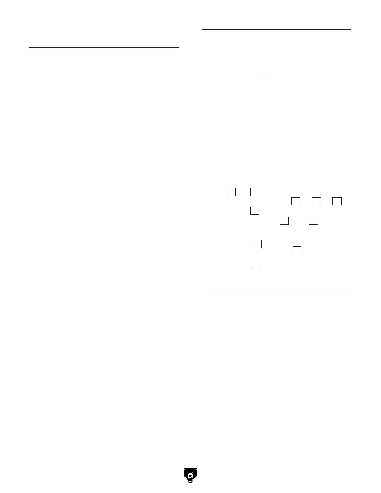
Inventory
The following is a list of items shipped with your
machine. Before beginning setup, lay these items
out and inventory them.
If any non-proprietary parts are missing (e.g. a
nut or a washer), we will gladly replace them; or
for the sake of expediency, replacements can be
obtained at your local hardware store.
Box 1 (Figure 3) Qty
A. Hold-Down Clamp Assembly ..................... 1
B. Adjustable Feet w/Hex Nuts ....................... 4
C. Hold-Down Bar ........................................... 1
D. Shoulder Screws ........................................ 2
E. Handle Springs ........................................... 2
F. Lock Handles.............................................. 2
G. Handle Standoff Hex Nuts.......................... 2
H. Lock Washer 12mm .................................... 1
I. Flat Washer 12mm ..................................... 1
J. Hex Nut M12-1.75 ....................................... 1
K. Fender Washer 8mm .................................. 1
L. Indexing Guide Collar ................................. 1
M. Hex Wrenches 4, 5, 6, 8mm .................1 Ea.
A
B
C D
H I J
E
K L
F
M
G
Figure 3. Inventory items.
Model G0846 (Mfd. Since 02/18)
-13-
Page 16

The unpainted surfaces of your machine are
coated with a heavy-duty rust preventative that
prevents corrosion during shipment and storage.
This rust preventative works extremely well, but it
will take a little time to clean.
Be patient and do a thorough job cleaning your
machine. The time you spend doing this now will
give you a better appreciation for the proper care
of your machine's unpainted surfaces.
There are many ways to remove this rust preventative, but the following steps work well in a wide
variety of situations. Always follow the manufacturer’s instructions with any cleaning product you
use and make sure you work in a well-ventilated
area to minimize exposure to toxic fumes.
Before cleaning, gather the following:
• Disposable rags
• Cleaner/degreaser (WD•40 works well)
• Safety glasses & disposable gloves
• Plastic paint scraper (optional)
Basic steps for removing rust preventative:
1.
2.
3.
4.
Many cleaning solvents
work in a well-ventilated
Cleanup
Cleanup
Gasoline and petroleum
products have low flash
points and can explode
or cause fire if used to
clean machinery. Avoid
using these products
to clean machinery.
Put on safety glasses.
Coat the rust preventative with a liberal
amount of cleaner/degreaser, then let it soak
for 5–10 minutes.
Wipe off the surfaces. If your cleaner/degreas-
er is effective, the rust preventative will wipe
off easily. If you have a plastic paint scraper,
scrape off as much as you can first, then wipe
off the rest with the rag.
are toxic if inhaled. Only
area.
NOTICE
Avoid harsh solvents like acetone or brake
parts cleaner that may damage painted surfaces. Always test on a small, inconspicuous location first.
T23692—Orange Power Degreaser
A great product for removing the waxy shipping grease from the non-painted parts of the
machine during clean up.
Repeat Steps 2–3 as necessary until clean,
then coat all unpainted surfaces with a quality
metal protectant to prevent rust.
-14-
Figure 4. T23692 Orange Power Degreaser.
Figure ??. T23692 Orange Power Degreaser.
Model G0846 (Mfd. Since 02/18)
Page 17

Site Considerations
Weight Load
Refer to the
of your machine. Make sure that the surface upon
which the machine is placed will bear the weight
of the machine, additional equipment that may be
installed on the machine, and the heaviest workpiece that will be used. Additionally, consider the
weight of the operator and any dynamic loading
that may occur when operating the machine.
Space Allocation
Consider the largest size of workpiece that will
be processed through this machine and provide
enough space around the machine for adequate
operator material handling or the installation of
auxiliary equipment. With permanent installations,
leave enough space around the machine to open
or remove doors/covers as required by the maintenance and service described in this manual.
See below for required space allocation.
Physical Environment
Extreme conditions for this type of machinery are
Place this machine near an existing power source.
other hazards. Make sure to leave enough space
Shadows, glare, or strobe effects that may distract
Machine Data Sheet for the weight
Children or untrained people
may be seriously injured by
this machine. Only install in an
access restricted location.
The physical environment where the machine is
operated is important for safe operation and longevity of machine components. For best results,
operate this machine in a dry environment that is
free from excessive moisture, hazardous chemicals, airborne abrasives, or extreme conditions.
generally those where the ambient temperature
range exceeds 41°–104°F; the relative humidity
range exceeds 20%–95% (non-condensing); or
the environment is subject to vibration, shocks,
or bumps.
Electrical Installation
Make sure all power cords are protected from
traffic, material handling, moisture, chemicals, or
around machine to disconnect power supply or
apply a lockout/tagout device, if required.
Lighting
= Electrical Connection
Lighting around the machine must be adequate
enough that operations can be performed safely.
or impede the operator must be eliminated.
36"
Figure 5. Minimum working clearances.
Model G0846 (Mfd. Since 02/18)
40"
-15-
Page 18

Lag shield anchors with lag screws (see below)
are a popular way to anchor machinery to a concrete floor, because the anchors sit flush with the
floor surface, making it easy to unbolt and move
the machine later, if needed. However, anytime
local codes apply, you MUST follow the anchoring
methodology specified by the code.
Anchoring machinery to the floor prevents tipping
or shifting and reduces vibration that may occur
during operation, resulting in a machine that runs
slightly quieter and feels more solid.
If the machine will be installed in a commercial or
workplace setting, or if it is permanently connected (hardwired) to the power supply, local codes
may require that it be anchored to the floor.
If not required by any local codes, fastening the
machine to the floor is an optional step. If you
choose not to do this with your machine, we recommend placing it on machine mounts, as these
provide an easy method for leveling and they have
vibration-absorbing pads.
Lifting & Placing
get help from other people
Anchoring to Floor
HEAVY LIF T!
Straining or crushing injury
may occur from improperly
lifting machine or some of
its parts. To reduce this risk,
and use a forklift (or other
lifting equipment) rated for
weight of this machine.
Use a forklift and lifting strap rated for at least 500
lbs. to lift the machine.
To lift and place machine:
1. Thread lifting strap between elevation
leadscrew and vertical elevation ways, as
shown in Figure 6.
Number of Mounting Holes ............................ 4
Diameter of Mounting Hardware .................
3
⁄8"
Anchoring to Concrete Floors
Lifting
Strap
Vertical
Elevation
Ways
Figure 6. Lifting strap placement.
2. Attach lifting strap to forklift forks, then center
and lock all table adjustments.
3. Remove fasteners securing machine to shipping pallet.
4. Lift machine enough to remove pallet and
place in position.
-16 -
Elevation
Leadscrew
Lag Screw
Flat Washer
Machine Base
Concrete
Figure 7. Popular method for anchoring
machinery to a concrete floor.
Model G0846 (Mfd. Since 02/18)
Lag Shield Anchor
Drilled Hole
Page 19

Assembly
The machine must be fully assembled before it
can be operated. Before beginning the assembly
process, refer to
and gather
all
To ensure the assembly process
goes smoothly, first clean any
covered or coated in heavy-duty rust preventative (if
applicable).
3. Slide hold-down clamp assembly over holddown post using either mounting hole for now
(see Figure 10). Tighten lock handle.
Needed for Setup
listed items.
parts that are
To assemble machine:
1. Loosely attach (1) lock handle to hold-down
clamp assembly (see Figure 8).
Hold-Down
Clamp Assembly
Lock
Handle
Mounting
Holes
Lock
Handle
Hold-Down
Post
Figure 10. Placement of hold-down clamp
assembly.
4. Place collar inside end of indexing guide with
flat side facing out, then secure to stud with
8mm fender washer, standoff hex nut, lock
handle, compression spring, and shoulder
screw (see Figure 11).
Figure 8. Lock handle attached to hold-down
clamp assembly.
2. Attach hold-down post to table with 12mm flat
washer, 12mm lock washer, and M12-1.75
hex nut (see Figure 9).
Figure 9. Mounting hold-down post to table.
Model G0846 (Mfd. Since 02/18)
Indexing
Guide
Standoff
Hex Nut
Lock
Handle
Figure 11. Installing components on indexing
guide shaft.
Collar
-17-
Page 20

5. Attach handle to table height handwheel (see
Figure 12) and tighten.
Dust Collection
BACK INJURY HAZARD!
DO NOT overexert yourself
moving your machine—use
assistance for next step.
6. To install adjustable feet, have an assistant
tilt machine and place it on 4 x 4 wood block
for safety, as shown in Figure 12.
7. Attach (2) feet in mounting holes under main
cabinet and secure each foot with hex nut
(see Figure 12). Repeat for opposite side.
Note: For permanent floor mounting, refer to
Anchoring to Floor on Page 16.
This machine creates a lot of wood chips/
dust during operation. Breathing airborne
dust on a regular basis can result in permanent respiratory illness. Reduce your risk
by wearing a respirator and capturing the
dust with a dust-collection system.
Minimum CFM at Dust Port: 400 CFM
Do not confuse this CFM recommendation with
the rating of the dust collector. To determine the
CFM at the dust port, you must consider these
variables: (1) CFM rating of the dust collector,
(2) hose type and length between the dust collector and the machine, (3) number of branches
or wyes, and (4) amount of other open lines
throughout the system. Explaining how to calculate these variables is beyond the scope of
this manual. Consult an expert or purchase a
good dust collection "how-to" book.
To connect dust collection system to machine:
Handwheel
Handle
Wood Block
Figure 12. Installing adjustable feet to base.
1. Attach 4" dust hose to dust port under work
table where shown in Figure 13, and secure
in place with a hose clamp.
Work
Table
Dust Port
Figure 13. Dust port location.
2. Tug hose to make sure it does not come off.
Note: A tight fit is necessary for proper
performance.
-18-
Model G0846 (Mfd. Since 02/18)
Page 21

Test Run
Once assembly is complete, test run the machine
to ensure it is properly connected to power and
safety components are functioning correctly.
If you find an unusual problem during the test run,
immediately stop the machine, disconnect it from
power, and fix the problem BEFORE operating the
machine again. The
table in the
SERVICE section of this manual can help.
DO NOT start machine until all preceding
setup instructions have been performed.
Operating an improperly set up machine
ed results that can lead to serious injury,
Serious injury or death can result from
Troubleshooting
4. Turn machine ON, verify motor operation and
chuck rotation direction, then turn machine
OFF.
When spindle direction switch is turned to
"R," the chuck should rotate clockwise as you
face it. The motor should run smoothly and
without problems, vibration, or noises.
5. Turn spindle direction switch to "L" (left)
position, then turn machine ON. Verify motor
operation and chuck rotation direction, then
turn machine OFF.
When switch is turned to "L," the chuck
should rotate counterclockwise as you face it.
using this machine BEFORE understanding
its controls and related safety information.
DO NOT operate, or allow others to operate,
machine until the information is understood.
may result in malfunction or unexpect-
death, or machine/property damage.
The Test Run consists of verifying the following:
1) The motor powers up and runs correctly, and
2) the safety disabling mechanism on the switch
works correctly.
To test run machine:
6. Remove switch disabling key, as shown in
Figure 14. Try to start machine with paddle
switch. The machine should not start.
— If the machine does not start, the switch
disabling feature is working correctly.
— If the machine does start, immediately stop
the machine. The switch disabling feature
is not working correctly. This safety feature
must work correctly before proceeding with
regular operations. Call Tech Support for
help.
1. Clear all setup tools away from machine and
make sure chuck key is removed.
2. Connect machine to power supply.
3. Turn spindle direction switch to "R" (right)
position.
Model G0846 (Mfd. Since 02/18)
Figure 14. Removing switch disabling key from
paddle switch.
-19 -
Page 22

SECTION 4: OPERATIONS
The purpose of this overview is to provide the novice machine operator with a basic understanding
of how the machine is used during operation, so
the
discussed later
in this manual
Due to the generic nature of this overview, it is
not intended to be an instructional guide. To learn
more about specific operations, read this entire
manual,
training from experienced
machine operators
outside of this manual by reading "how-to" books,
trade magazines, or websites.
To reduce your risk of
serious injury, read this
entire manual BEFORE
To reduce risk of eye injury from flying
Operation Overview
machine controls/components
are easier to understand.
seek additional
, and do additional research
AMPUTAT ION HAZ ARD
Keep hands and body parts
away from spinning boring
bits!
To complete a typical operation, the operator
does the following:
1. Installs appropriate boring bit, mill end, or
router bit for operation, then removes hex
wrench.
IMPORTANT: DO NOT use mortising chisels.
2. Measures and marks cutting area on
workpiece, adjusts table travel stops, and
selects on-center index on indexing collar.
using machine.
chips or lung damage from breathing dust,
always wear safety glasses and a respirator
when operating this machine.
If you are not experienced with this type
of machine, WE STRONGLY RECOMMEND
that you seek additional training outside of
this manual. Read books/magazines or get
formal training before beginning any projects. Regardless of the content in this section, Grizzly Industrial will not be held liable
for accidents caused by lack of training.
-20-
3. Places workpiece flat on work table and
fence and ensures fence is set properly.
4. Uses work table feed handle and handwheel
to align workpiece measurements with bit.
5. Secures workpiece to work table with holddown clamp assembly.
6. Puts on safety glasses or face shield and
respirator.
7. Inspects bit spiral, selects appropriate chuck
rotation direction, and turns machine ON.
IMPORTANT: Ensure bit rotates so it pulls
out chips during operation.
CAUTION: Avoid plunging or mortising deep-
er than the spiral of the bid is designed. Avoid
mortising holes deeper than 4 times the
diameter of the bit. Whip can occur.
8. If using an end mill or performing a sidecutting operation, uses conventional milling
method and moves workpiece against rotation of the bit. DO NOT use climb-milling
method.
Model G0846 (Mfd. Since 02/18)
Page 23

9. Uses work table feed handle to slowly move
workpiece into bit, bores hole, then moves
workpiece away from bit.
1
10. Limits depth of each cutting pass to
⁄16" or
less.
11. Turns machine OFF when operations are
complete.
• When mortising through hard spots in wood,
use shorter bits with 4-flute design so small
bites can be made and bit is less likely to
grab hard spots as 2-flute bits can do.
• Avoid deep cuts with bits where spirals
become buried or partially buried in workpiece
and cannot expel shavings. When mortising,
1
limit cutting depth to
⁄16" per pass.
12. Unclamps and removes workpiece only after
chuck has come to a complete stop.
Operating Tips
Cutting tools are sharp and
can easily cause laceration
injuries. Always protect
your hands with leather
gloves or shop rags when
handling cutting tools.
Here are a few things you can do to ensure easy
operation and better workpiece results:
• Use the correct bit for the job. Adjust the
chuck rotation so the bit pulls out chips during
the boring operation.
• Never rush a drilling or mortising procedure.
Extra care during setup will ensure satisfactory results.
Changing Bits
The Westcott-style 5⁄8" chuck included with the
Model G0846 is designed to work best with
shank slot mortising bits (see Figure 15). DO
NOT install or use vertical mortiser chisel bits.
5
⁄8"
• When using bits of different profiles and
design, take time to understand what makes
them different and how your process or technique may have to change.
5
• Use bits with a
⁄8" shank for safe, consistent
results during operation. Bits with smallerdiameter shanks have an increased risk
of breaking or coming loose during boring
operations, which may result in injury.
3
• To use bits with a
⁄4" shank, use the T28358
Westcott-style chuck (refer to Accessories
on Page 26).
• For longer or deeper mortises, 4-flute bits
are recommended for smaller chip size and
faster chip removal.
Model G0846 (Mfd. Since 02/18)
5
Figure 15. A selection of Grizzly
⁄8" fluted bits
suitable for use with the Model G0846.
Always ensure the bit is firmly secured in place
before any boring or mortising operation. When
changing bits, follow the instructions below.
Items Needed Qty
Hex Wrench 6mm.............................................. 1
Leather Gloves ...........................................1 Pair
To change bit:
1. DISCONNECT MACHINE FROM POWER!
2. Put on leather gloves to reduce the chance
of laceration injuries from sharp flute edges
when handling bits.
-21-
Page 24

3. If necessary, rotate bit by hand to gain access
to chuck collar hex screw.
4. Rotate hex wrench counterclockwise to open
chuck jaws and remove bit (see Figure 16).
Adjusting Table
The Model G0846 has a handwheel to move
the table up and down up to 5
left rear side of the table measures vertical table
movement (see Figure 19). A lock lever on the
right side of the knee secures table elevation
height.
1
⁄2 ". A scale on the
Chuck
Guard
Access
Slot
Boring
Bit
Figure 16. Removing bit from chuck.
5. Install bit into chuck and rotate hex wrench
clockwise to firmly tighten chuck (see Figure
17). DO NOT allow chuck to grab drill bit
flutes.
IMPORTANT: When installing a bit, ensure it
is centered in the chuck jaw before tightening
the chuck.
Adjustable stop knobs limit table travel. Two stop
knobs on the front of the table control up to 12
of side-to-side travel. One stop knob under the left
side of the table controls 6" of table travel depth.
When calculating table height and boring measurements for the operation, always test settings
on a scrap workpiece, and use it to mark layout
lines for setting the three stop knobs.
Items Needed Qty
Tape Measure or Ruler...................................... 1
Scrap Workpiece ............................... As Needed
1
⁄2 "
Adjusting Table Height and Depth
Stop
1. Install bit (see Changing Bits on Page 21).
2. Loosen table lock lever, then rotate handwheel
to adjust table height (see Figure 18). Refer
to scale as needed (see Figure 19).
Figure 17. Tightening bit in chuck.
6. When bit is secure, remove hex wrench and
re-connect machine to power.
-22-
Table Elevation
Handwheel
Table Lock Lever
Figure 18. Table elevation adjustments.
3. Loosen depth-stop knob and push table
toward chuck until bit extends beyond table
lip (see Figure 19) for drilling operation.
Place a tape measure or ruler against fence
face to measure bit depth.
Model G0846 (Mfd. Since 02/18)
Page 25

4. Move depth-stop knob against side-stop pin
to match position measured in Step 3 (see
Figure 19). Tighten knob.
Using & Adjusting
Miter Gauge & Fence
Table
Lip
Depth-
Stop
Knob
Table
Height
Scale
Figure 19. Table height and depth stop
adjustments.
5. Move table in and out to confirm depth setting. If necessary, repeat Steps 2–3.
6. Tighten table lock lever.
Side-
Stop
Pin
Adjusting Table Side-To-Side Stops
1. After adjusting table depth stop, loosen and
move left and right stop knobs away from
front stop pin (see Figure 20).
The Model G0846 features an adjustable fence
with miter gauge that pivots up to 60º left or right
for angled boring operations (see Figure 21).
Fence Lock
Knobs
Fence Miter
Scale
Indicator
Figure 21. Fence and miter gauge components.
Always ensure the workpiece sits firmly against
the fence. Use a backer board for additional support if needed (see Using Hold-Down Clamp
Assembly on Page 24).
Miter
Gauge
Lock Knob
Left Stop Knob Right Stop Knob
Front Stop Pin
Figure 20. Left-to-right table stop adjustments.
Align layout lines on scrap workpiece with
2.
drill bit, then move corresponding stop knobs
against front stop pin to set side-to-side travel.
3. Tighten stop knobs and move table side to
side to confirm measurement.
4. Perform boring operation on scrap workpiece
to confirm measurements.
The fence, miter gauge, and indicator can be
removed for larger workpieces.
Items Needed Qty
Hex Wrench 2.5mm ........................................... 1
Precision Square ............................................... 1
Adjusting Miter Gauge
1. Loosen lock knob (see Figure 21), adjust
fence to desired angle shown on miter scale,
then tighten lock knob to secure setting.
2. Refer to Adjusting Miter Gauge Indicator on
Page 32 to calibrate miter scale accurately.
Adjusting Fence Position
1. Loosen fence lock knobs (see Figure 21) and
shift fence as needed to support workpiece.
2. When complete, tighten fence lock knobs.
Model G0846 (Mfd. Since 02/18)
-23-
Page 26

Removing Fence, Miter Gauge, and
Indicator
1. Remove lock knob and flat washer, then lift
fence and miter gauge as assembly off table
(see Figure 21 on Page 23).
2. Loosen set screw in miter gauge bar to
remove indicator.
4. Ensure your workpiece is held securely to
table so it does not move during drilling operation. If necessary, lower hold-down clamp
arm to increase clamping pressure.
5. To ensure a small workpiece is clamped
securely, insert backer board between fence
and workpiece to extend fence reach (see
Figure 23).
Using Hold-Down
Clamp Assembly
The Model G0846 table features an adjustable hold-down clamp assembly to secure your
workpiece to the table during boring operations.
Always clamp your workpiece to the table. Place
the hold-down clamp assembly in the hold-down
post mounting hole (see Figure 22) that best supports the workpiece.
To operate hold-down clamp:
1. With clamp lock handle in unlocked position
(as shown in Figure 22), loosen lock handle
and center hold-down clamp arm and holddown pad over workpiece.
Lock
Handle
Clamp Lock
Handle
(Unlocked)
Hold-Down
Clamp Arm
Workpiece
Fence
Backer
Board
Figure 23. Small workpiece supported with
backer board.
Using Indexing
Guide
The work table features an adjustable indexing
guide for repeatable boring operations in increments of
used for line-boring operations or drilling holes for
dowel joinery.
To use and adjust indexing guide:
5
⁄8", 3⁄4", 7⁄8", and 1". This is typically
Hold-Down
Pad
Mounting
Holes
Figure 22. Hold-down clamp assembly
2. Lower hold-down arm until hold-down pad
lightly touches work surface, then tighten lock
handle.
3. Lift clamp lock handle and pull it forward to
securely clamp workpiece to table.
-24-
Hold-Down
Post
components.
1. Pull lock pin out and rotate it clockwise 90° to
disengage indexing guide (see Figure 24).
Indexing
Guide
Lock
Pin
Indexing
Holes
Figure 24. Indexing guide components.
Model G0846 (Mfd. Since 02/18)
Scale
Lock
Handle
Page 27

2. Loosen lock handle, rotate indexing guide to
desired bore spacing shown on scale, then
tighten lock handle to secure setting (see
Figure 24).
Note: Indexing guide clicks into position on
each row of indexing holes.
3. Attach workpiece to table, then adjust table
stops for boring operation (refer to Adjusting
Table on Page 22).
4. Rotate lock pin clockwise and move table
to seat pin in desired indexing hole (see
Figure 24) to lock table in position for drilling
operation.
3. Pull lock pin out and rotate it 90° clockwise to
disengage indexing guide (see Figure 25).
Chuck
Feed
Handle
Lock
Pin
5. Move table and workpiece away from bit,
then turn machine ON.
6. Use feed handle to slowly move table and
workpiece into bit to drill first hole, then move
table and workpiece away from bit.
7. Pull lock pin out, then move table sideways
until lock pin seats in next indexing hole.
Repeat Steps 6–7 until index drilling operation is complete.
8. When complete, disconnect machine from
power and remove workpiece.
Boring Workpiece
Freehand
When the indexing guide is disengaged, this
machine can be used "freehand" by the operator
to perform a wide range of slotting and boring
operations, making it ideal for slot mortises and
other loose tenon joinery.
To bore a workpiece freehand:
1. Measure and mark workpiece, then install
selected boring bit into chuck.
Figure 25. Controls for freehand boring
operation.
4. Use feed handle to align bit with one outer
reference mark and feed workpiece no more
1
⁄16" into bit, then move workpiece across
than
bit to remove material between reference
marks (see Figure 26).
Reference
Mark
Cutting Process for
Slotted Mortise
1
⁄16"
1
⁄16"
1
⁄16"
1
⁄16"
WORKPIECE
(TOP CUT-AWAY VIEW)
1
1
1
⁄16"
⁄16"
⁄16"
Reference
Mark
Figure 26. Cutting process for slotted mortise.
5. Repeat Step 4, moving workpiece into bit in
1
⁄16" increments until all material is removed to
measured depth.
2. Clamp workpiece to table and adjust table as
necessary for workpiece operation (refer to
Adjusting Table on Page 22).
Model G0846 (Mfd. Since 02/18)
6. When complete, disconnect machine from
power and remove workpiece.
-25-
Page 28

ACCESSORIES
Installing unapproved accessories may
order online at www.grizzly.com or call 1-800-523-4777
SECTION 5: ACCESSORIES
cause machine to malfunction, resulting in
serious personal injury or machine damage.
To reduce this risk, only install accessories
recommended for this machine by Grizzly.
NOTICE
Refer to our website or latest catalog for
additional recommended accessories.
Basic Eye Protection
T20501—Face Shield Crown Protector 4"
T20502—Face Shield Crown Protector 7"
T20503—Face Shield Window
T20451—“Kirova” Clear Safety Glasses
T20452—“Kirova” Anti-Reflective S. Glasses
T20456—DAKURA Safety Glasses, Black/Clear
Slot Mortising Bits for G0846
T32923—1⁄2" Bit, 1⁄2" Shank
T32924—5⁄8" Bit, 1⁄2" Shank
T32925—3⁄4" Bit, 1⁄2" Shank
T28358—20mm Chuck for G0846
This Westcott-style chuck allows use of bits with
3
⁄4" shanks on the G0846 Horizontal Slot Mortiser.
Figure 28. T28358 20mm Chuck.
T20502
T20503
T20456
Figure 27. Basic eye protection.
T20452
T20451
Recommended Metal Protectants
G5562—SLIPIT® 1 Qt. Gel
G5563—SLIPIT® 12 Oz. Spray
Figure 29. Recommended products for protect-
ing unpainted cast iron/steel parts on machinery.
-26-
Model G0846 (Mfd. Since 02/18)
Page 29

SECTION 6: MAINTENANCE
To reduce risk of shock or
accidental startup, always
disconnect machine from
Cleaning &
Protecting
power before adjustments,
maintenance, or service.
Schedule
For optimum performance from this machine, this
maintenance schedule must be strictly followed.
Ongoing
To maintain a low risk of injury and proper
machine operation, if you ever observe any of the
items below, shut down the machine immediately
and fix the problem before continuing operations:
• Vibration.
• Loose mounting bolts.
• Damaged chuck or bit.
• Worn or damaged wires.
• Any other unsafe condition.
Weekly/Monthly Maintenance (as required
based on workload and operating environment)
• Clean/vacuum wood chips and sawdust off of
motor, and out of chuck jaws.
Cleaning the Model G0846 is relatively easy.
Vacuum excess wood chips and sawdust, and
wipe off the remaining dust with a dry cloth. If any
resin has built up, use mineral spirits to remove it,
then when dry apply a light coat of oil.
Protect the unpainted cast-iron work table by wiping it clean after every use—this ensures moisture
from wood dust does not remain on bare metal
surfaces. Keep the table rust-free with regular
applications of products like SLIPIT
26 for more details).
®
(see Page
Bit Care
A horizontal boring machine bit requires proper
care.
• Store the bits so their sharp points and flutes
are protected. A wooden or plastic box that
keeps bits from touching one another works
best.
• Keep bits clean and rust free.
• Lubricate work table handle points, holddown clamp, chuck jaws, work table elevation
ways, work table leadscrew, and work table
roller bearing tracks (refer to Lubrication on
Page 28).
Model G0846 (Mfd. Since 02/18)
• Store lightly oiled.
• Have bits sharpened as soon as they show
any signs of dulling.
-27-
Page 30

Lubrication
Hold-Down Clamp & Chuck Jaws
Lubrication Frequency ........... 8 hrs. of Operation
Oil .............. Grizzly T27914 or ISO 68 Equivalent
It is essential to clean components before lubricating them. Dust and chips build up on lubricated
components, causing sludge that makes them
hard to move. Simply adding more lubricant
to gummy components will not yield smooth
movement.
Clean the components in this section with mineral
spirits, a rag, or a bristle brush as directed.
The following components need lubrication:
• Work table handle points
• Hold-down clamp
• Chuck jaws
• Table elevation ways
• Table leadscrew
• Table roller bearing V-ways
Items Needed Qty
Stiff Cleaning Brush .......................................... 1
Shop Rags ......................................... As Needed
Mineral Spirits .................................... As Needed
Grease: NLGI #2 or Grizzly T26419 .. As Needed
Oil: ISO 68 or Grizzly T27914 ............ As Needed
Table Handle Points
Lubrication Frequency ........... 8 hrs. of Operation
Oil .............. Grizzly T27914 or ISO 68 Equivalent
Apply a drop of oil to the hold-down clamp cam
(see Figure 31).
To clean and lubricate chuck jaws:
1. DISCONNECT MACHINE FROM POWER!
2. Remove chuck guard (see Figure 31).
Hold-Down
Clamp Cam
Chuck Guard
Figure 31. Lubrication points for hold-down
clamp cam and chuck jaws.
3. Brush, vacuum, or blow out dust and wood
chips.
Clean sawdust and debris from table handle
points (see Figure 30) with mineral spirits and
a brush. When dry, apply a thin coat of oil to the
points shown. Move the table through the entire
range of motion to evenly distribute the oil.
Handle
Points
Figure 30. Handle lubrication points.
-28-
4. Clean any accumulated oil and wood dust off
of chuck with mineral spirits.
5. Apply a drop of oil to each chuck jaw.
6. Re-install chuck guard.
Model G0846 (Mfd. Since 02/18)
Page 31

Table Elevation Ways
Lubrication Frequency ........... 8 hrs. of Operation
Oil .............. Grizzly T27914 or ISO 68 Equivalent
To lubricate table elevation ways, fully lower the
table with the elevation handwheel (see Figure
32). Clean each way with mineral spirits, let dry,
then apply a light coat of oil. Raise and lower the
table to evenly distribute the oil.
Table
Elevation
Way
(1 of 2)
Elevation
Handwheel
3. Apply thin coat of NLGI#2 grease to threads.
4. Raise and lower table to evenly distribute
grease.
Table Roller Bearing V-Ways
Lubrication Frequency ... 8 hrs. Or As Necessary
Grease ...... Grizzly T26419 or NLGI#2 Equivalent
Remove accumulated sludge caused by sawdust
and debris from the table roller bearing V-ways
and wheels as often as necessary to maintain
smooth table movement.
To lubricate table roller bearing V-ways:
1. Use mineral spirits, stiff brush, and shop rags
to clean table roller bearing V-ways and roller
bearing wheels where shown in Figure 34.
Roller Bearing
V-Ways (3 of 4)
Figure 32. Table elevation ways lubrication
points.
Table Elevation Leadscrew
Lubrication Frequency ......... 90 hrs. of Operation
Grease ...... Grizzly T26419 or NLGI#2 Equivalent
To lubricate table elevation leadscrew:
1. Fully lower table (see Figure 33).
Elevation
Handwheel
Table
Elevation
Leadscrew
Figure 33. Leadscrew lubrication point.
Roller Bearing Wheels
Figure 34. Cleaning and lubrication points for
table roller bearing V-ways and wheels (left side
shown).
2. Allow to dry.
3. Apply thin coat of grease to V-ways.
4. Move table back and forth and side to side to
evenly distribute grease.
Note: If after lubrication you notice that the
table has excessive free play, two eccentric
rods under the right side of the work table can
be adjusted. Refer to Adjusting Table Roller
Bearings on Page 33.
2. Clean threads with mineral spirits and allow
to dry.
Model G0846 (Mfd. Since 02/18)
-29-
Page 32

Review the troubleshooting procedures in this section if a problem develops with your machine. If you need
the
serial number and manufacture date of your machine before calling.
SECTION 7: SERVICE
replacement parts or additional help with a procedure, call our Technical Support. Note: Please gather
Troubleshooting
Motor & Electrical
Symptom Possible Cause Possible Solution
Machine does not
start or a breaker
trips.
Machine has
vibration or noisy
operation.
Machine slows or
stalls.
1. Incorrect power supply voltage or circuit
size.
2. Power supply circuit breaker tripped or fuse
blown.
3. Motor wires connected incorrectly.
4. Spindle rotation switch miswired or at fault.
5. Switch disabling key removed.
6. Start capacitor is at fault.
7. Wiring is open/has high resistance.
8. Power ON/OFF switch is at fault.
9. Centrifugal switch is at fault.
10. Spindle rotation switch at fault.
11. Motor is at fault.
1. Motor mount loose.
2. Motor or component is loose.
3. Bit not mounted correctly.
4. Machine is incorrectly mounted or sits
unevenly on floor.
5. Motor fan is rubbing on fan cover.
6. Centrifugal switch is at fault.
7. Motor bearings at fault.
1. Workpiece material is not suitable for this
machine, or machine undersized for the
task.
2. Motor connection is wired incorrectly.
3. Workpiece crooked; hold-down clamp loose
or misadjusted.
4. Motor has overheated.
5. Centrifugal switch is at fault.
6. Motor is at fault.
1. Ensure correct power supply voltage and circuit
size.
2. Ensure circuit is sized correctly and free of shorts.
Reset circuit breaker or replace fuse.
3. Correct motor wiring connections (Page 39).
4. Rewire or replace switch.
5. Install switch disabling key (Page 19).
6. Test/replace if faulty.
7. Check for broken wires or disconnected/corroded
connections, and repair/replace as necessary.
8. Replace faulty ON/OFF switch.
9. Adjust/replace the centrifugal switch if available.
10. Test/replace switch.
11. Test/repair/replace.
1. Tighten.
2. Inspect/replace stripped or damaged bolts/nuts, and
re-tighten with thread-locking fluid.
3. Remove and re-install bit (Page 21).
4. Tighten/replace fasteners; relocate/shim machine.
5. Replace dented fan cover; replace loose/damaged
fan.
6. Replace centrifugal switch.
7. Test by rotating chuck; rotational grinding/loose
shaft requires bearing replacement.
1. Only drill wood products; make sure moisture
content is below 20% and use sharp bits/reduce
feed pressure.
2. Correct motor wiring connections (Page 39).
3. Straighten or replace workpiece/adjust hold-down
clamp pressure (Page 24).
4. Clean off motor, let cool, and reduce workload.
5. Adjust/replace centrifugal switch.
6. Test/repair/replace.
-30-
Model G0846 (Mfd. Since 02/18)
Page 33

Operation
Symptom Possible Cause Possible Solution
Mortises are
irregular.
Machine slows when
operating.
Holes not drilled
straight into
workpiece.
Mortise and tenons
don't line up well.
Erratic work table
movement.
1. Chip or feed pressure too great.
2. Chips loading up bit.
1. Applying too much pressure to workpiece.
2. Too many chips binding the cut.
3. Bit is dull, or bit rotation is incorrect.
1. Work table loose.
2. Chuck is not square to the table.
3. Motor is not parallel to the table.
4. Bit is loose in chuck.
5. Bit comes loose or slips during boring
operation.
1. Table wheels loose in V-ways.
2. Table gib out of adjustment.
1. Wood chips, sawdust and debris caught in
work table handle points.
2. Wood chips, sawdust and debris caught in
work table roller bearing tracks.
3. Wood chips, sawdust and debris caught in
work table leadscrew.
4. Wood chips, sawdust and debris caught in
work table elevation ways.
5. Work table gib too loose/too tight.
1. Use bit with bigger cleanout spirals/reduce feed
pressure.
2. Reduce cutting depth, make more passes, or
sharpen/replace bit.
1. Feed workpiece slower; use less pressure.
2. Pull workpiece frequently out of bit to clear chips.
3. Replace bit/inspect, reverse chuck rotation.
1. Tighten table lock lever to increase rigidity during
operations; adjust table roller bearings (Page 33).
2. Inspect and square chuck to table (Page 33).
3. Adjust motor-table parallelism (Page 35).
4. Service/clean/tighten chuck (Page 28).
5. Use bits with
cutting depth/avoid plunge cuts.
1. Clean table wheels/V-ways; adjust wheel eccentric
rods (Page 29).
2. Adjust gib (Page 32).
1. Clean and lubricate table handle points (Page 28).
2. Clean and lubricate table roller bearing V-ways and
wheels (Page 29).
3. Clean and lubricate table leadscrew (Page 29).
4. Clean and lubricate table elevation ways (Page 29);
adjust table roller bearings (Page 33).
5. Adjust gib (Page 32).
5
⁄8" shank/use shorter bit/reduce
Model G0846 (Mfd. Since 02/18)
-31-
Page 34

Adjusting Fence
& Miter Gauge
Indicator
The miter gauge indicator is adjusted at the factory and shows the angle of the fence relative to
the table.
Adjust the indicator if it shifts out of alignment,
or if the fence, miter gauge, and indicator were
removed to perform an oversized boring
Items Needed Qty
Precision Square ............................................... 1
Hex Wrench 2.5mm........................................... 1
To adjust fence and miter gauge indicator:
1. Loosen miter gauge lock knob (see
Figure 35).
operation.
Adjusting Table Gib
The Model G0846 has a gib on the right side of
the knee that applies pressure on the elevation
way dovetail as the work table moves up and
down. It is adjustable with two set screws. The
upper set screw has a lock nut (see Figure 36).
Table Gib Set
Screw & Lock
Nut (Upper)
Table Lock
Lever
Table Gib Set
Screw (Lower)
Lock KnobMiter Gauge
Fence
Indicator
Set Screw
Figure 35. Miter gauge adjustments.
2. Place precision square against fence face.
Adjust fence until it is 90° to table, then tighten miter gauge lock knob.
3. Loosen set screw in miter gauge bar and
move indicator to align it with 90° mark on
miter gauge scale (see Figure 35). Tighten
set screw to secure setting.
Figure 36. Table elevation gib adjustment
locations.
If the gib is too loose, the quality of boring operations will suffer because the table will have loose,
sloppy movement against the dovetails. If the gib
is too tight, it will be difficult to raise and lower the
table.
The goal of adjusting the gib is to keep the vertical movement of the table snug, without excessive
looseness or binding.
Items Needed Qty
Open-End Wrench 14mm .................................. 1
Hex Wrench 4mm .............................................. 1
To adjust gib:
1. DISCONNECT MACHINE FROM POWER!
2. Loosen table lock lever (see Figure 36).
3. Loosen lock nut on upper gib adjustment set
screw (see Figure 36).
-32-
Model G0846 (Mfd. Since 02/18)
Page 35

4. If table moves up and down with excessive
looseness, tighten both gib adjustment set
screws until gib is snug against elevation
way dovetail, then back off gib adjustment set
screws
1
⁄8 turn.
Squaring Chuck with
Table
5. Use elevation handwheel to move table
up and down to test gib adjustment. Table
should move easily without excessive looseness or binding. If necessary, re-adjust set
screws and test table movement again.
6. After completing gib adjustment, hold upper
set screw in position and tighten lock nut to
secure gib in position.
Adjusting Table Roller Bearings
If you notice that the table has excessive free play
when moving left/right, two eccentric rods on the
two roller bearings under the right side of the table
can be adjusted to reduce free play.
Items Needed Qty
Open-End Wrench 16mm .................................. 1
The axis of the chuck was set 90° to the table at
the factory. This ensures boring operations will be
horizontally squared in the workpiece.
If boring holes are no longer accurate on a
workpiece, as shown in Figure 37, refer to
Troubleshooting on Page 30 to rule out other
solutions first, then perform the following procedure to realign the chuck and table.
Dowel
Chuck
Axis
Square
with
Table
90° 90°
Workpiece
(Top View)
Dowel
Chuck
Axis
NOT
Square
with
Table
Workpiece
(Top View)
To adjust table roller bearings:
1. DISCONNECT MACHINE FROM POWER!
2. Clean table roller bearings and V-ways
(refer to Table Roller Bearings Tracks on
Page 29).
3. Use wrench on each upper hex nut to turn
eccentric rod and adjust roller bearing wheel
location in V-way track, then lift table to test
for free play.
4. Adjust each eccentric rod until table free play
is eliminated and table moves smoothly in all
directions.
Hole
Figure 37. Determining if chuck axis is square to
table.
IMPORTANT: Refer to Adjusting Fence & Miter
Gauge Indicator on Page 32, Adjusting Table
Gib on Page 32, and Adjusting Table Roller
Bearings on this page before proceeding with
these instructions.
Items Needed Qty
Precision Square 6" ........................................... 1
Drill Rod
Open-End Wrench 13 mm .................................. 2
Open-End Wrench 16mm .................................. 1
Hex Wrench 6mm.............................................. 1
To inspect and square chuck with table:
1. DISCONNECT MACHINE FROM POWER!
5
⁄8" x 8" .............................................. 1
Hole
Model G0846 (Mfd. Since 02/18)
-33-
Page 36

2. Clean and service chuck (refer to Hold-Down
Clamp & Chuck Jaws on Page 28).
3. Follow instructions in Adjusting Table Roller
Bearings on Page 33.
5
4. Mount drill rod (round, straight metal
⁄8"
diameter) in chuck (see Figure 38). Rotate
by chuck hand to ensure rod is straight and
doesn't wobble.
7. Remove (2) flat head screws from chuck
guard and separate it from motor cover (see
Figure 39).
Motor
x 2
Cover
5. Raise table just under drill rod, then tighten
table lock lever (see Figure 38).
6. Place precision square evenly along table lip
so it touches drill rod (see Figure 38).
—If there is no gap between the square
and drill rod anywhere along its length,
no adjustment is necessary. The chuck is
square to the table. No further adjustments
are necessary.
— If there is a gap between the square and
drill rod at either end of the table, the chuck
is not square to the table. Proceed to Step
7.
Table
Lock
Table
Lip
Lever
Chuck
Guard
Figure 39. Removing chuck guard.
8. Remove (4) hex nuts, lock washers, and flat
washers securing motor cover to machine
body, then lift off cover.
9. Loosen (4) hex nuts securing motor to
machine body (see Figure 40), and shift
motor to square chuck with table. Repeat
Steps 5–6 to adjust motor position until
chuck is square to table.
Motor Chuck
Hex Nuts
(2 of 4)
Guard
Drill Rod
Precision
Square
Figure 38. Checking chuck-to-table square.
-34-
Figure 40. Loosening motor mount hex nuts.
10. Tighten hex nuts to secure motor setting.
11. Re-install motor cover and chuck guard.
Model G0846 (Mfd. Since 02/18)
Page 37

Adjusting Table
To verify table parallelism with chuck:
Parallelism with
Chuck
The motor and chuck axis was set parallel with
the table by the factory. This ensures boring operations will be vertically squared in the workpiece
If boring holes are no longer perpendicular to
the workpiece, as shown in Figure 41, refer to
Troubleshooting on Page 30 to rule out other
solutions first, then perform the following procedure to reset table parallelism.
Dowel
Hole
Workpiece
(Side View)
90°
Table
Parallel
with Chuck Axis
1. DISCONNECT MACHINE FROM POWER!
2. Clean and service chuck (refer to Hold-Down
Clamp & Chuck Jaws on Page 28).
3. Follow instructions in Adjusting Table Roller
Bearings on Page 33.
5
4. Mount drill rod (round, straight metal
⁄8"
diameter) in chuck. Rotate by chuck hand to
ensure rod is straight and doesn't wobble.
5. Raise table until there is approximately 1"
gap between table surface and bottom of drill
rod (see Figure 42), then tighten table lock.
6. Set adjustable square against drill rod and
table at chuck end, as shown in Figure 42,
then tighten square to secure measurement.
5
Adjustable
Square
⁄8" Drill
Rod
Dowel
Hole
90°
Workpiece
(Side View)
Table NOT
Parallel
with Chuck Axis
Figure 41. Determining if chuck axis is parallel
with table.
IMPORTANT: Refer to Adjusting Table Gib on
Page 32 and Adjusting Table Roller Bearings
on Page 33 before proceeding with these
instructions.
Items Needed Qty
Adjustable Square ............................................. 1
5
Drill Rod
⁄8" x 8" ............................................... 1
Open-End Wrench 13mm .................................. 1
Hex Wrench 6mm .............................................. 1
About
1" Gap
Figure 42. Checking table-chuck axis
parallelism.
7. Move square to opposite end of drill rod to
check parallelism.
—If measurements at both ends of drill rod
are equal, no adjustment is necessary. The
chuck is parallel to the table.
—If measurements at both ends of drill rod
are not equal, the chuck is not parallel to
the table. Proceed to Step 8.
Model G0846 (Mfd. Since 02/18)
-35-
Page 38

8. Loosen (3) lock nuts on adjustment cap
screw (see Figure 43).
Adjusting Table
—To lower outer edge of table, rotate cap
screw clockwise.
—To raise outer edge of table, rotate cap
screw counterclockwise.
Lock Nuts
Adjustment
Cap Screw
Figure 43. Adjustments for table-motor
parallelism.
Vertical Height
The table moves a total of 5 1⁄2 " and features a cap
screw that functions as a depth stop to adjust the
table height for boring operations.
Items Needed Qty
Open-End Wrench 14 mm .................................. 1
Hex Wrench 6mm.............................................. 1
To adjust table vertical height:
1. DISCONNECT MACHINE FROM POWER!
2. Loosen lock nut (see Figure 44).
—To raise table height, turn cap screw
counterclockwise.
—To lower table height, turn cap screw
clockwise.
9. Repeat Steps 6–8 and adjust cap screw as
needed until table is parallel to chuck axis.
10. Tighten lock nuts on adjustment cap screw to
secure table parallelism.
Depth Stop
Lock Nut
Table
Vertical
Height
Cap Screw
Figure 44. Table vertical height adjustments.
3. Test depth stop by inserting boring bit into
chuck, clamping a sample workpiece to table,
and raising table with elevation handwheel
until depth stop contacts stop block.
4. Adjust depth stop as needed, then tighten
lock nut to secure setting.
-36-
Model G0846 (Mfd. Since 02/18)
Page 39

These pages are current at the time of printing. However, in the spirit of improvement, we may make changes to the electrical systems of future machines. Compare the manufacture date of your machine to the one
number and manufacture date of your
machine before calling. This information can be found on the main machine label.
machine
SECTION 8: WIRING
stated in this manual, and study this section carefully.
If there are differences between your machine and what is shown in this section, call Technical Support at
(570) 546-9663 for assistance BEFORE making any changes to the wiring on your machine. An updated
wiring diagram may be available. Note: Please gather the serial
Wiring Safety Instructions
SHOCK HAZARD. Working on wiring that is con-
nected to a power source is extremely dangerous.
Touching electrified parts will result in personal
injury including but not limited to severe burns,
electrocution, or death. Disconnect the power
from the machine before servicing electrical components!
MODIFICATIONS. Modifying the wiring beyond
what is shown in the diagram may lead to unpredictable results, including serious injury or fire.
This includes the installation of unapproved aftermarket parts.
WIRE CONNECTIONS. All connections must
be tight to prevent wires from loosening during
machine operation. Double-check all wires disconnected or connected during any wiring task to
ensure tight connections.
CIRCUIT REQUIREMENTS. You MUST follow
the requirements at the beginning of this manual
when connecting your machine to a power source.
WIRE/COMPONENT DAMAGE. Damaged wires
or components increase the risk of serious personal injury, fire, or machine damage. If you notice
that any wires or components are damaged while
performing a wiring task, replace those wires or
components.
MOTOR WIRING. The motor wiring shown in
these diagrams is current at the time of printing
but may not match your machine. If you find this
to be the case, use the wiring diagram inside the
motor junction box.
CAPACITORS/INVERTERS. Some capacitors
and power inverters store an electrical charge for
up to 10 minutes after being disconnected from
the power source. To reduce the risk of being
shocked, wait at least this long before working on
capacitors.
EXPERIENCING DIFFICULTIES. If you are experiencing difficulties understanding the information
included in this section, contact our Technical
Support at (570) 546-9663.
The photos and diagrams
included in this section are
best viewed in color. You
can view these pages in
color at www.grizzly.com.
Model G0846 (Mfd. Since 02/18)
READ ELECTRICAL SAFETY
ON PAGE 37!
-37-
Page 40

Electrical Components
Figure 45. Junction box wiring.
Figure 47. Rotary switch (left side).
Figure 46. ON/OFF switch wiring (rear view).
-38-
READ ELECTRICAL SAFETY
ON PAGE 37!
Figure 48. Rotary switch (right side).
Model G0846 (Mfd. Since 02/18)
Page 41

Ground
Wiring Diagram
Run Capacitor
30uF
450V
U2
220V Motor
Machine Body
Paddle Switch
KEDU HY18
Ground
ON/OFF
2 5
V2
U1
V1
Ground
Motor Junction Box
Machine Body
KEDU
3
63
1C
C
2
4
ZH-HC-4
(Right
Side)
Spindle
41
Rotation
Switch
10
6
C
9
5
8
7C
KEDU
ZH-HC-4
(Left
Side)
Model G0846 (Mfd. Since 02/18)
Hot
220
VAC
6-15 Plug
Hot
Ground
READ ELECTRICAL SAFETY
ON PAGE 37!
-39-
Page 42

27
SECTION 9: PARTS
Please Note: We do our best to stock replacement parts whenever possible, but we cannot guarantee that all parts shown here
are available for purchase. Call (800) 523-4777 or visit our online parts store at www.grizzly.com to check for availability.
30
Base, Column & Motor
29
41
2
28
31
42
43
44
45
21
3 4
17
22
18
20
32
46
19
26
25
32
33
34
35
23
38
39
40
36
37
35-3
35-5
35-7
35-1
35-2
35-4
35-6
35-8
24
5
6
7
12
13
14
8
10
11
9
-40-
BUY PARTS ONLINE AT GRIZZLY.COM !
Scan QR code to visit our Parts Store.
15
16
Model G0846 (Mfd. Since 02/18)
Page 43

Base, Column & Motor Parts List
REF PART # DESCRIPTION REF PART # DESCRIPTION
2 P0846002 HEX NUT M10-1.5 28 P0846028 CHUCK GUARD
3 P0846003 DOUBLE-BOLT M10-1.5 29 P0846029 ROTATION DIRECTION LABEL
4 P0846004 FENDER WASHER 10MM 30 P0846030 PHLP HD SCR M6-1 X 16
5 P0846005 CAP SCREW M8-1.25 X 70 31 P0846031 HEX NUT M6-1
6 P0846006 HEX NUT M8-1.25 32 P0846032 HEX NUT M10-1.5
7 P0846007 FLAT WASHER 8MM 33 P0846033 FLAT WASHER 10MM
8 P0846008 BASE 34 P0846034 LOCK WASHER 10MM
9 P0846009 ADJUSTABLE FOOT M10-1.5 X 24, 50D 35 P0846035 MOTOR 2HP 220V 1-PH
10 P0846010 HEX NUT M10-1.5 35-1 P0846035-1 MOTOR JUNCTION BOX
11 P0846011 COLUMN 35-2 P0846035-2 MOTOR FAN COVER
12 P0846012 CAP SCREW M10-1.5 X 35 35-3 P0846035-3 MOTOR FAN
13 P0846013 FLAT WASHER 10MM 35-4 P0846035-4 R CAPACITOR 30M 450V 1-5/8"' X 3''
14 P0846014 LOCK WASHER 10MM 35-5 P0846035-5 CONTACT PLATE
15 P0846015 DOOR 35-6 P0846035-6 CENTRIFUGAL SWITCH
16 P0846016 DOOR LOCK W/ 2 KEYS 35-7 P0846035-7 BALL BEARING 6204-2RS
17 P0846017 SWITCH COVER PLATE 35-8 P0846035-8 BALL BEARING 6204-2RS
18 P0846018 PHLP HD SCR M4-.7 X 10 36 P0846036 MOTOR MOUNTING BASE
19 P0846019 SWITCH BOX GASKET 37 P0846037 HEX BOLT M8-1.25 X 30
20 P0846020 SWITCH BOX 38 P0846038 HEX NUT M8-1.25
21 P0846021 SWITCH ADAPTER PLATE 39 P0846039 FLAT WASHER 8MM
22 P0846022 PHLP HD SCREW M4-.7 X 16 40 P0846040 LOCK WASHER 8MM
23 P0846023 FWD/REV SWITCH KEDU ZH-HC-4 41 P0846041 CAP SCREW M6-1 X 20
24 P0846024 STRAIN RELIEF TYPE-3 M20-1.5 42 P0846042 CHUCK
25 P0846025 PADDLE SWITCH KEDU HY18 43 P0846043 SET SCREW M8-1.25 X 16
26 P0846026 MOTOR COVER 44 P0846044 STRAIN RELIEF TYPE-3 M20-1.5
27 P0846027 RUBBER PLATE 45 P0846045 MOTOR CORD 10G 3W 24"
Model G0846 (Mfd. Since 02/18)
BUY PARTS ONLINE AT GRIZZLY.COM !
Scan QR code to visit our Parts Store.
-41-
Page 44

Table Knee
135
133
140
148
138
107
136
141
142
147
137
113
139
134
109
108
130
132
129
156
151
131
119
155
128
157
117
158
127
172
116
152
103
114
118
104
105
122
110
126
125
171
170
115
112
111
121
123
-42-
146
BUY PARTS ONLINE AT GRIZZLY.COM !
Scan QR code to visit our Parts Store.
145
149
150
168
169
163
162
165
167
166
153
154
159
160
161
164
124
120
Model G0846 (Mfd. Since 02/18)
Page 45

Table Knee Parts List
REF PART # DESCRIPTION REF PART # DESCRIPTION
103 P0846103 LOCK WASHER 10MM 138 P0846138 HANDWHEEL HUB PLATE
104 P0846104 FLAT WASHER 10MM 139 P0846139 PLATE
105 P0846105 HEX NUT M10-1.5 140 P0846140 CAP SCREW M8-1.25 X 35
107 P0846107 SET SCREW M6-1 X 12 141 P0846141 HEX NUT M8-1.25
108 P0846108 SET SCREW M8-1.25 X 40 142 P0846142 FLAT WASHER 8MM
109 P0846109 HEX NUT M8-1.25 145 P0846145 HANDWHEEL TYPE-18 138D X 15B-K
110 P0846110 TABLE KNEE WAYS 146 P0846146 HANDWHEEL HANDLE
111 P0846111 CAP SCREW M6-1 X 55 147 P0846147 HEX NUT M8-1.25
112 P0846112 HEX NUT M6-1 148 P0846148 ACORN NUT M12-1.75
113 P0846113 TABLE KNEE 149 P0846149 GEAR SHAFT M12-1.75 X 12
114 P0846114 INSERT PLATE 150 P0846150 PIN 5 X 12
115 P0846115 SET SCREW M8-1.25 X 25 151 P0846151 EXT RETAINING RING 18MM
116 P0846116 LOCKING HANDLE M10-1.5 X 25 152 P0846152 HEX NUT M10-1.5
117 P0846117 HEX BOLT M10-1.5 X 150 153 P0846153 FLAT WASHER 10MM
118 P0846118 FLAT WASHER 10MM 154 P0846154 GEARBOX
119 P0846119 HEX NUT M10-1.5 155 P0846155 HEX BOLT M6-1 X 65
120 P0846120 HANDLE BRACKET 156 P0846156 LOCK WASHER 6MM
121 P0846121 HEX BOLT M8-1.25 X 25 157 P0846157 EXT RETAINING RING 10MM
122 P0846122 LOCK WASHER 8MM 158 P0846158 FLAT WASHER 10MM
123 P0846123 FLAT WASHER 8MM 159 P0846159 FLAT WASHER 10MM
124 P0846124 FLAT HD CAP SCR M6-1 X 12 160 P0846160 HELICAL GEAR
125 P0846125 HANDLE LEVER 161 P0846161 ROLL PIN 4 X 25
126 P0846126 HANDLE GRIP 162 P0846162 GUIDE SCREW
127 P0846127 COVER PLATE 163 P0846163 THRUST BEARING 51102
128 P0846128 PHLPS HD SCR M4-.7 X 6 164 P0846164 BUSHING
129 P0846129 DEPTH SCALE 165 P0846165 CAP SCREW M6-1 X 12
130 P0846130 PHLPS HD SCR M4-.7 X 6 166 P0846166 LOCK WASHER 6MM
131 P0846131 POINTER 167 P0846167 FLAT WASHER 6MM
132 P0846132 PHLPS HD SCR M4-.7 X 6 168 P0846168 PHLP HD SCR M4-.7 X 10
133 P0846133 LOCK PLATE 169 P0846169 DUST PORT 4"
134 P0846134 CAP SCREW M6-1 X 12 170 P0846170 SET SCREW M8-1.25 X 25
135 P0846135 KNOB M6-1 30D, 22L, 4LOBES 171 P0846171 HEX NUT M8-1.25 THIN
136 P0846136 SPACER 172 P0846172 SET SCREW M8-1.25 X 20
137 P0846137 CARRIAGE BOLT M6-1 X 20
Model G0846 (Mfd. Since 02/18)
BUY PARTS ONLINE AT GRIZZLY.COM !
Scan QR code to visit our Parts Store.
-43-
Page 46

Table
202
205
262
229
243
REF PART # DESCRIPTION REF PART # DESCRIPTION
216
217
224
222
218
225
220
223
227
226
221
219
228
201
244
204
245
203
233
246
239
236
235
232
238
240
242
206
209
237
234
241
210
248
207
247
252
249
204
250
215
254
251
203
253
214
255
213
230
256
231
208
211
212
257
259
201 P0846201 WORK TABLE 231 P0846231 FLAT WASHER 6MM
202 P0846202 TABLE MOUNTING BRACKET 232 P0846232 SLIDING BASE
203 P0846203 PHLP HD SCR M4-.7 X 10 233 P0846233 LOCKING AXLE
204 P0846204 FLAT WASHER 4MM 234 P0846234 FLAT WASHER 10MM
205 P0846205 CAP SCREW M8-1.25 X 16 235 P0846235 HEX NUT M10-1.5
206 P0846206 CAP SCREW M6-1 X 12 236 P0846236 IDLER WHEEL
207 P0846207 END PLATE 237 P0846237 BALL BEARING 6000-2RS
208 P0846208 PIN BASE 238 P0846238 EXT RETAINING RING 26MM
209 P0846209 CAP SCREW M5-.8 X 12 239 P0846239 TUBE
210 P0846210 LOCK WASHER 5MM 240 P0846240 HEX BOLT M10-1.5 X 25
211 P0846211 COMPRESSION SPRING 241 P0846241 FLAT WASHER 10MM
212 P0846212 PIN TUBE 242 P0846242 ECCENTRIC ROD
213 P0846213 LOCKING PIN 243 P0846243 HEX NUT M8-1.25
214 P0846214 ROLL PIN 3 X 12 244 P0846244 TABLE STOP
215 P0846215 KNOB M6-1, D30, 4-LOBE 245 P0846245 CAP SCREW M6-1 X 12
216 P0846216 X-AXIS LOCKING PLATE 246 P0846246 FLAT WASHER 6MM
217 P0846217 PHLP HD SCREW M5-.8 X 10 247 P0846247 INDEXING BAR BRACKET
218 P0846218 Y-AXIS LOCKING PLATE 248 P0846248 CAP SCREW M6-1 X 12
219 P0846219 PHLP HD SCREW M5-.8 X 10 249 P0846249 SET SCREW M5-.8 X 6
220 P0846220 LOCKING BLOCK 250 P0846250 COMPRESSION SPRING
221 P0846221 SET SCREW M6-1 X 8 251 P0846251 STEEL BALL 6MM
222 P0846222 KNOB BOLT M6-1 X 20, 30D, 4-LOBE 252 P0846252 SET SCREW M8-1.25 X 8
223 P0846223 SPACER 253 P0846253 LOCKING AXLE
224 P0846224 LOCKING BLOCK 254 P0846254 HEX NUT M8-1.25
225 P0846225 FIXED TRACK 255 P0846255 INDEXING BAR
226 P0846226 HEX BOLT M6-1 X 25 256 P0846256 INDEXING SCALE
227 P0846227 DOUBLE HEAD PIN M6-1 X 80 257 P0846257 COVER PLATE
228 P0846228 HEX NUT M6-1 259 P0846259 ADJUSTABLE HANDLE 116L, M5-8 X 8
229 P0846229 ADJUSTING TRACK 262 P0846262 CAP SCREW M6-1 X 8
230 P0846230 HEX BOLT M6-1 X 25
-44-
BUY PARTS ONLINE AT GRIZZLY.COM !
Scan QR code to visit our Parts Store.
Model G0846 (Mfd. Since 02/18)
Page 47

Hold-Down Assembly
412
Miter Gauge & Fence
311
312
310
314
301
313
302
304
305
303
315
316
317
307
318
REF PART # DESCRIPTION
301 P0846301 SUPPORT BAR
302 P0846302 HOLD DOWN BAR
303 P0846303 PLASTIC COVER
304 P0846304 LOCKING PLATE
305 P0846305 FLAT WASHER 8MM
307 P0846307 ADJUSTABLE HANDLE M8-1.25
310 P0846310 LOCKING BAR M8-1.25 X12
311 P0846311 LOCK LEVER
312 P0846312 ECCENTRIC BLOCK
313 P0846313 SET SCREW M6-1 X 8
314 P0846314 PIN 8 X 40
315 P0846315 PRESS AXLE
316 P0846316 COMPRESSION SPRING
317 P0846317 FLAT WASHER 12MM
318 P0846318 PRESS BLOCK
319 P0846319 ROLL PIN 4 X 20
319
407
406
405
410
408
409
411
403
404
401
413
402
REF PART # DESCRIPTION
401 P0846401 MITER GAUGE BODY
402 P0846402 SCALE LOCKING BLOCK
403 P0846403 POINTER
404 P0846404 SET SCREW M5-.8 X 8
405 P0846405 KNOB M8-1.25, D40, 4-LOBE
406 P0846406 MITER GAUGE FENCE
407 P0846407 END CAP
408 P0846408 KNURLED NUT M6-1
409 P0846409 HEX BOLT M6-1 X 40
410 P0846410 STUD-UDE M8-1.25 X 12, M6-1 X 20, 96L
411 P0846411 FENDER WASHER 6MM
412 P0846412 BLOCK
413 P0846413 ROLL PIN 3 X 6
414 P0846414 PHLP HD SCR M4-.7 X 16
415 P0846415 HEX NUT M4-.7
415
414
Model G0846 (Mfd. Since 02/18)
BUY PARTS ONLINE AT GRIZZLY.COM !
Scan QR code to visit our Parts Store.
-45-
Page 48
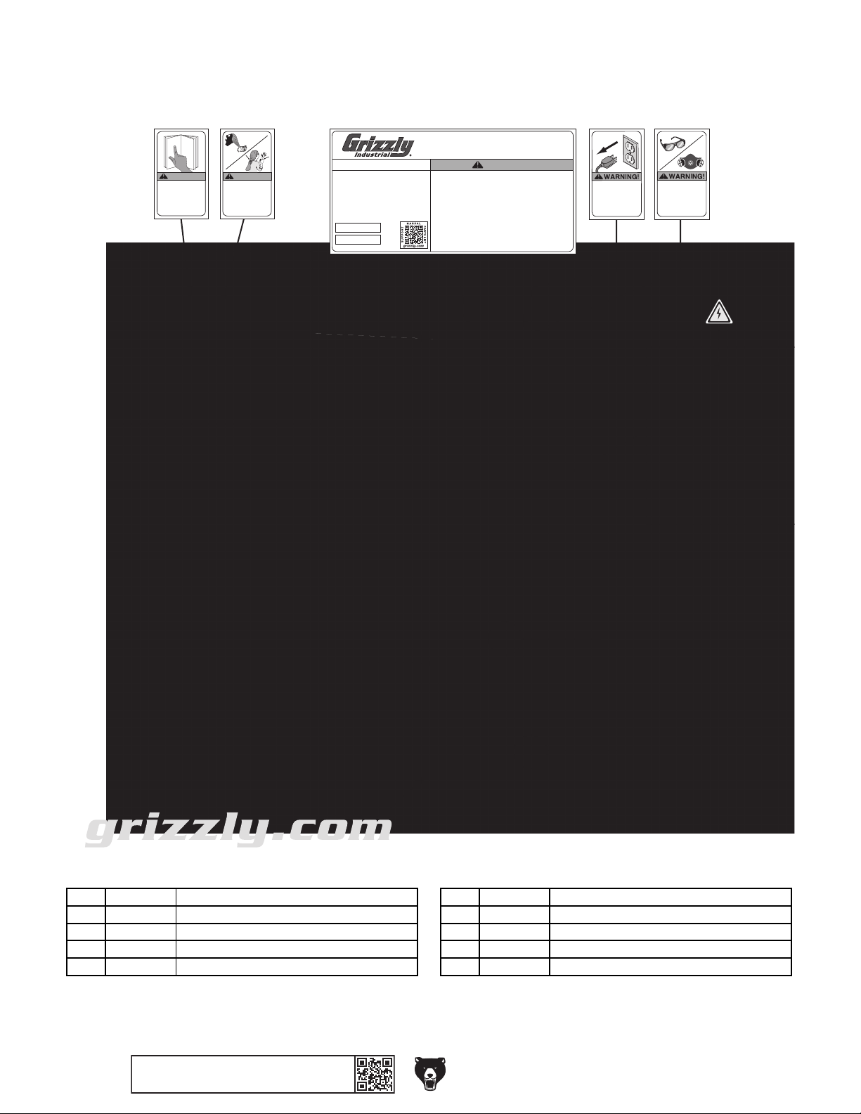
Labels & Cosmetics
REF PART # DESCRIPTION REF PART # DESCRIPTION
501 P0846501 READ MANUAL WARNING 506 P0846506 ELECTRICAL WARNING
502 P0846502 ENTANGLEMENT WARNING 507 P0846507 TOUCH-UP PAINT, GRIZZLY BEIGE
503 P0846503 MACHINE ID LABEL 508 P0846508 TOUCH-UP PAINT, GRIZZLY GREEN
504 P0846504 INJURY/SHOCK WARNING 509 P0846509 GRIZZLY.COM LABEL
505 P0846505 EYE/LUNG WARNING 510 P0846510 MODEL NUMBER LABEL
501 502 503 504 505
MODEL G0846
HORIZONTAL MORTISING MACHINE
WARNING!
To reduce risk of death
or serious injury, read
manual BEFORE using
machine.
To get a new manual,
call (800) 523-4777 or
go to www.grizzly.com.
WARNING!
ENTANGLEMENT
HAZARD!
Tie back long hair, roll up
long sleeves, and remove
loose clothing, jewelry, or
gloves to prevent getting
caught in moving parts.
Specifications
Motor: 2 HP, 220V, Single-Phase, 10A, 60 Hz
Motor Speed: 3400 RPM
Table Cross Travel: 6"
Table Longitudinal Travel: 12-1/2"
Table Vertical Travel: 5-1/2"
Chuck Capacity: 5/8"
Floor-to-Table Height: 30"–35-3/8"
Miter Gauge Adjustment: 45° Left/Right
Weight: 236 lbs.
Mfd. for Grizzly in China
Date
SN
To reduce risk of serious personal injury when using this machine:
1. Read and understand owner’s manual before operating.
2. Always wear ANSI-approved safety glasses.
3. Only plug power cord into a grounded outlet.
4. Disconnect power before setting up or servicing.
5. Keep all guards and covers in place during operation.
6. Avoid entanglement with spindle—tie back long hair, roll up long
sleeves, and DO NOT wear loose clothing, gloves, or jewelry.
7. Clamp workpiece to prevent rotation.
8. Avoid putting hands where they could slip into rotating bit and
chuck. Never reach around chuck while spindle is in motion.
9. DO NOT operate when tired or under influence of drugs or alcohol.
10. Make sure machine is properly adjusted and set up correctly before
starting motor.
11. DO NOT reach over spindle or worktable during machine operation.
12. Prevent unauthorized use by children or untrained users.
WARNING!
INJURY/SHOCK
HAZARD!
Disconnect power
before adjustments,
maintenance, or
service.
EYE/LUNG INJURY
Always wear safety
glasses and a
respirator when
using this machine.
HAZARD!
506
510
507
G0846
508
509
-46-
BUY PARTS ONLINE AT GRIZZLY.COM !
Scan QR code to visit our Parts Store.
Model G0846 (Mfd. Since 02/18)
Page 49

WARRANTY CARD
Name _____________________________________________________________________________
Street _____________________________________________________________________________
City _______________________ State _________________________ Zip _____________________
Phone # ____________________ Email _________________________________________________
Model # ____________________ Order # _______________________ Serial # __________________
The following information is given on a voluntary basis. It will be used for marketing purposes to help us develop
better products and services. Of course, all information is strictly confidential.
1. How did you learn about us?
____ Advertisement ____ Friend ____ Catalog
____ Card Deck ____ Website ____ Other:
2. Which of the following magazines do you subscribe to?
____ Cabinetmaker & FDM
____ Family Handyman
____ Hand Loader
____ Handy
____ Home Shop Machinist
____ Journal of Light Cont.
____ Live Steam
____ Model Airplane News
____ Old House Journal
____ Popular Mechanics
3. What is your annual household income?
____ $20,000-$29,000 ____ $30,000-$39,000 ____ $40,000-$49,000
____ $50,000-$59,000 ____ $60,000-$69,000 ____ $70,000+
CUT ALONG DOTTED LINE
4. What is your age group?
____ 20-29 ____ 30-39 ____ 40-49
____ 50-59 ____ 60-69 ____ 70+
5. How long have you been a woodworker/metalworker?
____ 0-2 Years ____ 2-8 Years ____ 8-20 Years ____20+ Years
6. How many of your machines or tools are Grizzly?
____ 0-2 ____ 3-5 ____ 6-9 ____10+
____ Popular Science
____ Popular Woodworking
____ Precision Shooter
____ Projects in Metal
____ RC Modeler
____ Rie
____ Shop Notes
____ Shotgun News
____ Today’s Homeowner
____ Wood
____ Wooden Boat
____ Woodshop News
____ Woodsmith
____ Woodwork
____ Woodworker West
____ Woodworker’s Journal
____ Other:
7. Do you think your machine represents a good value? _____Yes _____No
8. Would you recommend Grizzly Industrial to a friend? _____ Yes _____No
9. Would you allow us to use your name as a reference for Grizzly customers in your area?
Note: We never use names more than 3 times. _____Yes _____No
10. Comments: _____________________________________________________________________
_________________________________________________________________________________
_________________________________________________________________________________
_________________________________________________________________________________
Page 50

FOLD ALONG DOTTED LINE
FOLD ALONG DOTTED LINE
Place
Stamp
Here
GRIZZLY INDUSTRIAL, INC.
P.O. BOX 2069
BELLINGHAM, WA 98227-2069
Send a Grizzly Catalog to a friend:
Name_______________________________
Street_______________________________
City______________State______Zip______
TAPE ALONG EDGES--PLEASE DO NOT STAPLE
Page 51

that the merchandise complies with the provisions of any law or acts unless the manufacturer so warrants.
We shall in no event be liable for death, injuries to persons or property or for incidental, contingent, special,
The manufacturers reserve the right to change specifications at any time because they constantly strive to
Thank you again for your business and continued support. We hope to serve you again soon.
WARRANTY AND RETURNS
WARRANTY AND RETURNS
Grizzly Industrial, Inc. warrants every product it sells for a period of 1 year to the original purchaser from
the date of purchase. This warranty does not apply to defects due directly or indirectly to misuse, abuse,
negligence, accidents, repairs or alterations or lack of maintenance. This is Grizzly’s sole written warranty
and any and all warranties that may be implied by law, including any merchantability or fitness, for any particular purpose, are hereby limited to the duration of this written warranty. We do not warrant or represent
In no event shall Grizzly’s liability under this warranty exceed the purchase price paid for the product and
any legal actions brought against Grizzly shall be tried in the State of Washington, County of Whatcom.
or consequential damages arising from the use of our products.
To take advantage of this warranty, contact us by mail or phone and give us all the details. We will then
issue you a “Return Number,’’ which must be clearly posted on the outside as well as the inside of the
carton. We will not accept any item back without this number. Proof of purchase must accompany the
merchandise.
achieve better quality equipment. We make every effort to ensure that our products meet high quality and
durability standards and we hope you never need to use this warranty.
Please feel free to write or call us if you have any questions about the machine or the manual.
Page 52

 Loading...