

Page 1

MODEL G0827
HORIZONTAL/VERTICAL MILL w/DRO
OWNER'S MANUAL
(For models manufactured since 11/17)
COPYRIGHT © JANUARY, 2018 BY GRIZZLY INDUSTRIAL
WARNING: NO PORTION OF THIS MANUAL MAY BE REPRODUCED IN ANY SHAPE
OR FORM WITHOUT THE WRITTEN APPROVAL OF GRIZZLY INDUSTRIAL, INC.
#BLJHKB18713 PRINTED IN CHINA
V1.01.18
Page 2

This manual provides critical safety instructions on the proper setup,
operation, maintenance, and service of this machine/tool. Save this
document, refer to it often, and use it to instruct other operators.
Failure to read, understand and follow the instructions in this manual
may result in fire or serious personal injury—including amputation,
electrocution, or death.
The owner of this machine/tool is solely responsible for its safe use.
This responsibility includes but is not limited to proper installation in
a safe environment, personnel training and usage authorization,
proper inspection and maintenance, manual availability and comprehension, application of safety devices, cutting/sanding/grinding tool
integrity, and the usage of personal protective equipment.
The manufacturer will not be held liable for injury or property damage
from negligence, improper training, machine modifications or misuse.
Some dust created by power sanding, sawing, grinding, drilling, and
other construction activities contains chemicals known to the State
of California to cause cancer, birth defects or other reproductive
harm. Some examples of these chemicals are:
• Lead from lead-based paints.
• Crystalline silica from bricks, cement and other masonry products.
• Arsenic and chromium from chemically-treated lumber.
Your risk from these exposures varies, depending on how often you
do this type of work. To reduce your exposure to these chemicals:
Work in a well ventilated area, and work with approved safety equipment, such as those dust masks that are specially designed to filter
out microscopic particles.
Page 3

Table of Contents
INTRODUCTION ............................................... 2
Contact Info.................................................... 2
Manual Accuracy
Left Front View Identification
Right Front View Identification
Controls & Components
Machine Data Sheet
SECTION 1: SAFETY
Safety Instructions for Machinery
Additional Safety for Milling Machines
SECTION 2: POWER SUPPLY
SECTION 3: SETUP
Needed for Setup
Unpacking
Inventory
Cleanup
Site Considerations
Lifting & Placing
Leveling
Anchoring to Floor
Arbor/Chuck Assembly
Verifying Lubrication
Assembly
Power Connection........................................ 24
Test Run
Spindle Break-In
Inspections & Adjustments
SECTION 4: OPERATIONS
Operation Overview
Table Movement
Head Tilt....................................................... 31
Ram Movement............................................ 31
Installing/Removing Tooling
Spindle Speed.............................................. 36
Using Spindle Downfeed Controls
SECTION 5: ACCESSORIES
.................................................... 16
...................................................... 17
........................................................ 18
........................................................ 21
..................................................... 23
...................................................... 24
........................................... 2
......................... 3
....................... 4
................................. 5
...................................... 8
..................................... 11
................ 11
......... 13
...................... 14
....................................... 16
......................................... 16
...................................... 19
........................................... 20
....................................... 21
................................ 22
.................................... 22
.......................................... 28
.......................... 28
........................... 29
..................................... 29
.......................................... 30
......................... 32
............... 38
......................... 40
SECTION 6: MAINTENANCE
Schedule
Cleaning & Protecting
Lubrication
Adding/Changing Coolant
Tensioning/Replacing V-Belts
Machine Storage
SECTION 7: SERVICE
Troubleshooting
Tramming Mill Head
Adjusting Leadscrew Backlash
Adjusting Gibs
SECTION 8: WIRING
Wiring Safety Instructions
Wiring Overview
Component Location
Electrical Panel Wiring
Electrical Panel Wiring Diagram A
Electrical Panel Wiring Diagram B
Control Panel Wiring
Vertical Spindle Motor Wiring
Horizontal Spindle Motor Wiring
Coolant Pump Wiring
DRO Wiring
SECTION 9: PARTS
Vertical Gearbox
Vertical Spindle
Ram
Base & Column
Horizontal Spindle
Table
Knee Spindle................................................ 82
Electrical Box & Control Panel Components
Accessories & Tools
Labels & Cosmetics
WARRANTY & RETURNS
...................................................... 44
................................................... 45
.......................................... 54
................................... 55
........................................... 55
..................................... 58
.............................................. 61
...................................... 63
........................................... 64
.................................... 64
.................................... 68
................................... 70
.................................................. 70
....................................... 71
.......................................... 71
............................................ 73
............................................................. 75
............................................ 76
........................................ 78
............................................................ 80
.................................... 85
..................................... 86
......................... 44
.................................. 44
............................ 51
...................... 53
.................... 60
............................ 63
................................. 65
............... 66
............... 67
...................... 69
.................. 69
............................. 89
84
We stand behind our machines! If you have questions or need help, contact us with the information
below. Before contacting, make sure you get the
Page 4

serial number
machine ID label. This will help us help you faster.
We want your feedback on this manual. What did
you like about it? Where could it be improved?
Please take a few minutes to give us feedback.
Email: manuals@grizzly.com
We are proud to provide a high-quality owner’s
manual with your new machine!
We
instructions, specifications, drawings, and photographs
in this manual. Sometimes we make mistakes, but
our policy of continuous improvement also means
that
you receive is
slightly different than shown in the manual
If you find this to be the case, and the difference
between the manual and machine leaves you
confused or unsure about something
check our
website for an updated version. W
current
manuals and
on our web-
site at
Alternatively, you can call our Technical Support
for help. Before calling, make sure you write down
the
from
the machine ID label (see below). This information
is required for us to provide proper tech support,
and it helps us determine if updated documentation is available for your machine.
INTRODUCTION
Contact Info
and manufacture date from the
Grizzly Technical Support
1815 W. Battlefield
Springfield, MO 65807
Phone: (570) 546-9663
Email: techsupport@grizzly.com
Grizzly Documentation Manager
P.O. Box 2069
Bellingham, WA 98227-2069
Manual Accuracy
made every effort to be exact with the
sometimes the machine
.
,
e post
manual updates for free
www.grizzly.com.
Manufacture Date and Serial Number
Manufacture Date
Serial Number
-2-
Model G0827 (Mfd. Since 11/17)
Page 5

Left Front View Identification
To reduce your risk of
serious injury, read this
entire manual BEFORE
Vertical
Spindle
using machine.
Motor
Horizontal Arbor
Support
X-Axis
Handwheel
Ram
LED Work
Light
Master
Control Panel
Quill Lock
Vertical
Spindle
Coolant
Nozzle
Electrical
Cabinet
Coolant
Pump
Model G0827 (Mfd. Since 11/17)
Splash
Pan
Base
-3-
Page 6

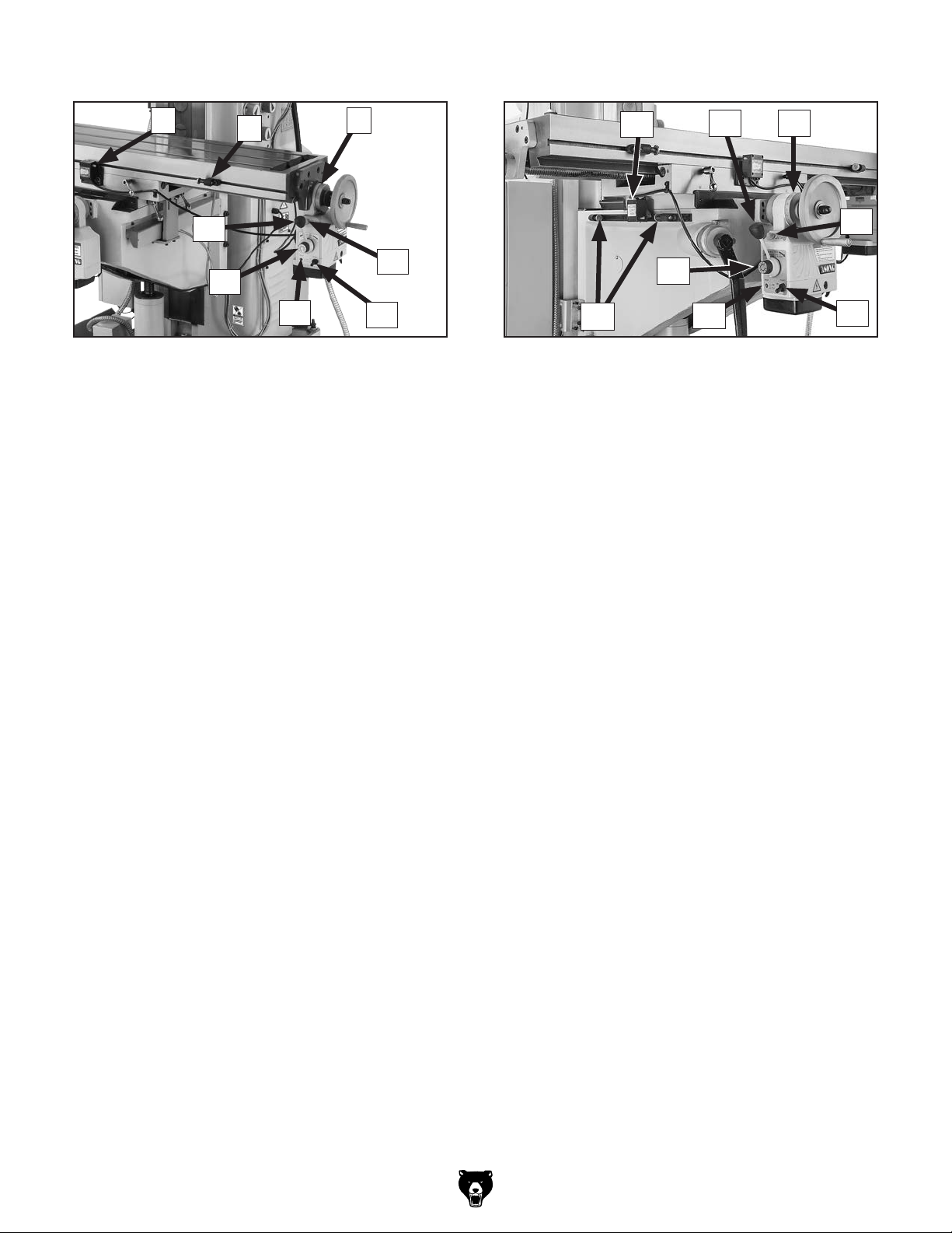
Right Front View Identification
To reduce your risk of
serious injury, read this
entire manual BEFORE
Vertical
Spindle Speed
Selectors
Fine
Downfeed
Handwheel
3-Axis
DRO
Horizontal
Spindle
X-Axis Table
Lock
(1 of 2)
using machine.
Coarse
Downfeed
Lever
Control
Panel
Downfeed
Selection
Lever
Ram
Lock Handle
(1 of 2)
Horizontal
Spindle Speed
Selectors
-4-
Z-Axis
Crank
Y-Axis
Handwheel
Y-Axis
Power
Feed
Y-Axis Table Lock
X-Axis
Handwheel
X-Axis
Power Feed
(1 of 2)
Model G0827 (Mfd. Since 11/17)
Page 7

Controls &
To reduce your risk of
serious injury, read this
entire manual BEFORE
Components
Control Panel
C
D
E
using machine.
Refer to Figures 1–8 and the following descriptions to become familiar with the basic controls
and components of this machine. Understanding
these items and how they work will help you
understand the rest of the manual and stay safe
when operating this machine.
Master Power Switch
A
F
I
Figure 2. Control panel.
C. FORWARD Button (Vertical Spindle ):
Starts vertical spindle forward rotation (clockwise looking down on headstock).
Spindle rotation direction can ONLY be
changed with spindle completely stopped.
D. REVERSE Button (Vertical Spindle ):
Starts vertical spindle reverse rotation (counterclockwise looking down on headstock).
G
J
H
K
B
Figure 1. Location of master power switch and
vertical spindle speed high/low range selector.
A. Vertical Spindle Speed High/Low Range
Selector: Selects either high or low vertical
spindle speed range.
B. Master Power Switch: Enables power to
flow to machine.
Model G0827 (Mfd. Since 11/17)
E. STOP Button (Vertical Spindle ): Stops
vertical spindle rotation.
F. FORWARD Button (Horizontal Spindle ):
Starts horizontal spindle forward rotation (counterclockwise as from front of machine).
G. REVERSE Button (Horizontal Spindle ):
Starts horizontal spindle reverse rotation (clockwise as from front of machine).
H. STOP Button (Horizontal Spindle ): Stops
horizontal spindle rotation.
I. POWER Lamp Button: When pressed, illu-
minates and enables power to control panel.
E-STOP button must be reset first.
J. E-STOP Button: Disables power to control
panel and stops all machine functions. To
reset, twist button clockwise until it pops out.
K. Coolant Pump Switch: Starts/stops coolant
pump.
-5-
Page 8
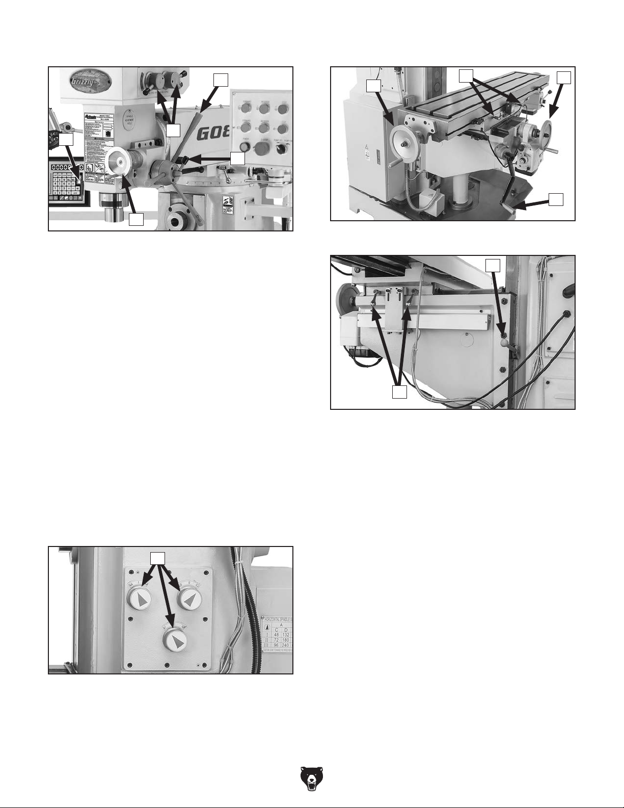
Table Headstock
M
L
P
N
O
Figure 3. Location of headstock controls.
L. Spindle Speed Selectors: Selects one of
four spindle speeds in selected speed range.
M. Coarse Downfeed Levers: Quickly
moves quill downward when pulled down.
Automatically retracts spindle to top position when released. Typically used for drilling
operations.
R
S
Figure 5. Table controls and components.
W
T
U
N. Downfeed Selection Lever: When tight-
ened, enables fine downfeed handwheel;
when loosened, enables coarse downfeed
levers.
O. Fine Downfeed Handwheel: Manually con-
trols vertical spindle downfeed for fine Z-axis
control.
P. Quill Lock: Locks quill in vertical position.
Column
Q
Figure 4. Location of horizontal spindle speed
selector knobs.
Q. Horizontal Spindle Speed Selector Knobs:
Configures gearing inside column to produce
various horizontal spindle speeds.
V
Figure 6. Location of Y- and Z-axis locks.
R. X-Axis Handwheel (1 of 2): Manually moves
table along X-axis (left and right).
S. X-Axis Table Locks: When tightened, pre-
vents X-axis table movement for increased
rigidity during operations where the X-axis
should not move.
T. Y-Axis Handwheel: Manually moves table
along Y-axis (front and back).
U. Knee Crank: Manually moves table along
Z-axis (up and down).
V. Y-Axis Table Locks: When tightened, pre-
vents Y-axis table movement for increased
rigidity during operations where the Y-axis
should not move.
W. Z-Axis Column Lock: When tightened, pre-
vents Z-axis table movement for increased
rigidity during operations where the Z-axis
should not move.
-6-
Model G0827 (Mfd. Since 11/17)
Page 9
X-Axis Power Feed Y-Axis Power Feed
Y
AA
AB
AC
Figure 7. X-Axis power feed components. Figure 8. Y-Axis power feed components.
X. X-Axis Limit Switch: Stops powered table
movement when either side plunger comes
in contact with limit stops.
. X-Axis Limit Stops: Limit X-axis table travel
Y
(one on each end of table).
. Graduated Dial: Displays X-axis table move-
Z
ment in 0.001" increments, with each revolution equaling 0.200" of travel.
ZX
AE
AD
. Y-Axis Limit Switch: Stops powered table
AF
movement when it comes in contact with limit
stops.
Directional Lever: Selects direction of table
AG.
movement. Center position is neutral.
. Graduated Dial: Displays Y-axis table move-
AH
ment in 0.001" increments, with each revolution equaling 0.200" of travel.
AF
AL
AM
AG AH
AK
AI
AJ
Directional Lever: Selects direction of table
AA.
movement. Center position is neutral.
. Speed Dial: Controls speed of table X-axis
AB
movement. Turning dial clockwise causes
table to move faster.
Note: A lot of variables are involved when
determining proper feed rates. We recommend that you combine research and experimentation to find feed rates that best work for
your specific operations.
AC. Reset Button: Resets internal circuit breaker
if power feed is overloaded and shuts down.
. ON/OFF Switch: Enables/disables power to
AD
power feed.
. Rapid-Traverse Button: Once directional
AE
lever has been activated, causes table to
travel at full speed but only while pushed.
IMPORTANT: Avoid contact with handwheel
while rapid-traverse is pressed; table
handwheel will rotate at a rapid rate.
. Rapid-Traverse Button: Once directional
AI
lever has been activated, causes table to
travel at full speed but only while pushed.
IMPORTANT: Avoid contact with handwheel
while rapid-traverse is pressed; table
handwheel will rotate at a rapid rate.
. ON/OFF Switch: Enables/disables power to
AJ
power feed unit.
AK. Reset Button: Resets internal circuit breaker
if power feed is overloaded and shuts down.
. Speed Dial: Controls speed of table Y-axis
AL
movement. Turning dial clockwise causes
table to move faster.
Note: A lot of variables are involved when
determining proper feed rates. We recommend that you combine research and experimentation to find feed rates that best work for
your specific operations.
. Y-Axis Limit Stops: Limits Y-axis table
AM
travel (one on either end of table).
Model G0827 (Mfd. Since 11/17)
-7-
Page 10

Machine Data Sheet
Bearings........................................................................................................ Sealed & Permanently Lubricated
MACHINE DATA
SHEET
Customer Service #: (570) 546-9663 · To Order Call: (800) 523-4777 · Fax #: (800) 438-5901
MODEL G0827 11" X 50" 2 HP HORIZONTAL/VERTICAL
MILL WITH DRO
Product Dimensions:
Weight............................................................................................................................................................ 2866 lbs.
Width (side-to-side) x Depth (front-to-back) x Height........................................................................... 65 x 67 x 85 in.
Footprint (Length x Width)............................................................................................................................ 41 x 24 in.
Space Required for Full Range of Movement (Width x Depth).................................................................... 94 x 71 in.
Shipping Dimensions:
Type.......................................................................................................................................................... Wood Crate
Content........................................................................................................................................................... Machine
Weight............................................................................................................................................................ 3087 lbs.
Length x Width x Height....................................................................................................................... 57 x 66 x 89 in.
Must Ship Upright................................................................................................................................................... Yes
Electrical:
Power Requirement................................................................................................................... 220V, 3-Phase, 60 Hz
Full-Load Current Rating....................................................................................................................................... 9.2A
Minimum Circuit Size.............................................................................................................................................. 15A
Connection Type....................................................................................................................................... Cord & Plug
Power Cord Included.............................................................................................................................................. Yes
Power Cord Length................................................................................................................................................. 6 ft.
Power Cord Gauge......................................................................................................................................... 14 AWG
Plug Included........................................................................................................................................................... No
Recommended Plug Type................................................................................................................................... 15-15
Motors:
Coolant Pump
Horsepower................................................................................................................................................. 40W
Phase.................................................................................................................................................... 3-Phase
Amps......................................................................................................................................................... 0.43A
Speed................................................................................................................................................ 3360 RPM
Type........................................................................................................................................... TEFC Induction
Power Transfer ............................................................................................................................... Direct Drive
Bearings........................................................................................................ Sealed & Permanently Lubricated
Centrifugal Switch/Contacts Type................................................................................................................ N/A
Horizontal Spindle Motor
Horsepower................................................................................................................................................ 3 HP
Phase.................................................................................................................................................... 3-Phase
Amps........................................................................................................................................................... 8.8A
Speed................................................................................................................................................ 1720 RPM
Type........................................................................................................................................... TEFC Induction
Power Transfer .................................................................................................................................. Belt Drive
-8-
Model G0827 (Mfd. Since 11/17)
Page 11

Vertical Spindle Motor
Horsepower................................................................................................................................................ 2 HP
Phase.................................................................................................................................................... 3-Phase
Amps...................................................................................................................................................... 5.4A/6A
Speed................................................................................................................................ 860 RPM/1720 RPM
Type........................................................................................................................................... TEFC Induction
Power Transfer ................................................................................................................................. Gear Drive
Bearings........................................................................................................ Sealed & Permanently Lubricated
Centrifugal Switch/Contacts Type................................................................................................................ N/A
Main Specifications:
Operation Info
Spindle Travel.............................................................................................................................................. 5 in.
Max Distance Spindle to Column........................................................................................................ 27-1/2 in.
Max Distance Spindle to Table.......................................................................................................... 17-1/16 in.
Maximum Distance Horizontal Spindle Center to Table............................................................................ 14 in.
Longitudinal Table Travel (X-Axis)............................................................................................................. 29 in.
Cross Table Travel (Y-Axis)................................................................................................................ 10-1/2 in.
Vertical Table Travel (Z-Axis)............................................................................................................ 13-9/16 in.
Ram Travel................................................................................................................................................ 18 in.
Turret or Column Swivel (Left /Right)................................................................................................... 180 deg.
Head Tilt (Left/Right).............................................................................................................................. 45 deg.
Drilling Capacity for Cast Iron.............................................................................................................. 1-3/16 in.
Drilling Capacity for Steel............................................................................................................................ 1 in.
End Milling Capacity.................................................................................................................................... 1 in.
Face Milling Capacity........................................................................................................................ 3-15/16 in.
Table Info
Table Length.............................................................................................................................................. 50 in.
Table Width................................................................................................................................................ 11 in.
Table Thickness.................................................................................................................................... 3-1/8 in.
Table Height (from Floor/Base)....................................................................................................... 32-15/16 in.
Number of T-Slots............................................................................................................................................ 3
T-Slot Size................................................................................................................................................ 5/8 in.
T-Slots Centers.................................................................................................................................. 3-15/16 in.
Number of Longitudinal Feeds.............................................................................................................. Variable
X-Axis Table Power Feed Rate....................................................................................................... 0 – 2.3 FPM
Y-Axis Table Power Feed Rate....................................................................................................... 0 – 2.3 FPM
X/Y-Axis Travel per Handwheel Revolution.......................................................................................... 0.200 in.
Z-Axis Travel per Handwheel Revolution............................................................................................. 0.100 in.
Spindle Info
Spindle Taper............................................................................................................................................... R-8
Number of Vertical Spindle Speeds.................................................................................................................. 8
Range of Vertical Spindle Speeds........................................................................................... 140 – 2100 RPM
Quill Diameter....................................................................................................................................... 3.543 in.
Drawbar Thread Size............................................................................................................................. 7/16-20
Drawbar Length............................................................................................................. 13-3/4 and 18-11/16 in.
Spindle Bearings.................................................................................................. Tapered Roller Bearings (P5)
Horizontal Spindle Taper.............................................................................................................................. R-8
Number of Horizontal Spindle Speeds........................................................................................................... 12
Range of Horizontal Spindle Speeds......................................................................................... 48 – 1560 RPM
Horizontal Spindle Bearing Type......................................................................... Tapered Roller Bearings (P5)
Model G0827 (Mfd. Since 11/17)
-9-
Page 12

Construction
Spindle Housing/Quill........................................................................................................... Chromed Cast Iron
Table....................................................................................................................... Precision-Ground Cast Iron
Head.................................................................................................................................................... Cast Iron
Column/Base....................................................................................................................................... Cast Iron
Base..................................................................................................................................................... Cast Iron
Stand.................................................................................................................................................... Cast Iron
Paint Type/Finish.................................................................................................................................... Enamel
Other Specifications:
Country of Origin ................................................................................................................................................ China
Warranty ........................................................................................................................................................... 1 Year
Approximate Assembly & Setup Time ............................................................................................................. 2 Hours
Serial Number Location ................................................................................................................... Machine ID Label
Sound Rating ..................................................................................................................................................... 83 dB
ISO 9001 Factory .................................................................................................................................................. Yes
Features:
3-Axis DRO
Horizontal and Vertical R-8 Spindles
P5 (ABEC-5 equivalent) High-Precision Spindle Bearings
8 Vertical Spindle Speeds from 140–2100 RPM
12 Horizontal Spindle Speeds from 48–1560 RPM
Independent X- and Y-Axis Power Feed
Built-In Coolant System
LED Worklamp
Accessories Included:
Toolbox w/Service Tools
1–13mm Drill Chuck with Arbor
R-8 x MT#3 Spindle Sleeve
MT#3 x MT#2 Spindle Sleeve
1" and 1-1/4" Horizontal Spindles
-10 -
Model G0827 (Mfd. Since 11/17)
Page 13

SECTION 1: SAFETY
For Your Own Safety, Read Instruction
Manual Before Operating This Machine
The purpose of safety symbols is to attract your attention to possible hazardous conditions.
This manual uses a series of symbols and signal words intended to convey the level of importance of the safety messages. The progression of symbols is described below. Remember that
safety messages by themselves do not eliminate danger and are not a substitute for proper
accident prevention measures. Always use common sense and good judgment.
Indicates an imminently hazardous situation which, if not avoided,
WILL result in death or serious injury.
Indicates a potentially hazardous situation which, if not avoided,
COULD result in death or serious injury.
Indicates a potentially hazardous situation which, if not avoided,
MAY result in minor or moderate injury. It may also be used to alert
against unsafe practices.
Alerts the user to useful information about proper operation of the
NOTICE
machine to avoid machine damage.
Safety Instructions for Machinery
OWNER’S MANUAL. Read and understand this
owner’s manual BEFORE using machine.
TRAINED OPERATORS ONLY. Untrained operators have a higher risk of being hurt or killed.
Only allow trained/supervised people to use this
machine. When machine is not being used, disconnect power, remove switch keys, or lock-out
machine to prevent unauthorized use—especially
around children. Make your workshop kid proof!
DANGEROUS ENVIRONMENTS. Do not use
machinery in areas that are wet, cluttered, or have
poor lighting. Operating machinery in these areas
greatly increases the risk of accidents and injury.
MENTAL ALERTNESS REQUIRED. Full mental
alertness is required for safe operation of machinery. Never operate under the influence of drugs or
alcohol, when tired, or when distracted.
ELECTRICAL EQUIPMENT INJURY RISKS.
You can be shocked, burned, or killed by touching
live electrical components or improperly grounded
machinery. To reduce this risk, only allow qualified
service personnel to do electrical installation or
repair work, and always disconnect power before
accessing or exposing electrical equipment.
DISCONNECT POWER FIRST.
nect machine from power supply BEFORE making adjustments, changing tooling, or servicing
machine. This prevents an injury risk from unintended startup or contact with live electrical components.
EYE PROTECTION. Always wear ANSI-approved
safety glasses or a face shield when operating or
observing machinery to reduce the risk of eye
injury or blindness from flying particles. Everyday
eyeglasses are NOT approved safety glasses.
Always discon-
Model G0827 (Mfd. Since 11/17)
-11-
Page 14

WEARING PROPER APPAREL. Do not wear
clothing, apparel or jewelry that can become
entangled in moving parts. Always tie back or
cover long hair. Wear non-slip footwear to reduce
risk of slipping and losing control or accidentally
contacting cutting tool or moving parts.
HAZARDOUS DUST. Dust created by machinery
operations may cause cancer, birth defects, or
long-term respiratory damage. Be aware of dust
hazards associated with each workpiece material. Always wear a NIOSH-approved respirator to
reduce your risk.
HEARING PROTECTION. Always wear hearing protection when operating or observing loud
machinery. Extended exposure to this noise
without hearing protection can cause permanent
hearing loss.
REMOVE ADJUSTING TOOLS. Tools left on
machinery can become dangerous projectiles
upon startup. Never leave chuck keys, wrenches,
or any other tools on machine. Always verify
removal before starting!
USE CORRECT TOOL FOR THE JOB. Only use
this tool for its intended purpose—do not force
it or an attachment to do a job for which it was
not designed. Never make unapproved modifications—modifying tool or using it differently than
intended may result in malfunction or mechanical
failure that can lead to personal injury or death!
AWKWARD POSITIONS. Keep proper footing
and balance at all times when operating machine.
Do not overreach! Avoid awkward hand positions
that make workpiece control difficult or increase
the risk of accidental injury.
CHILDREN & BYSTANDERS. Keep children and
bystanders at a safe distance from the work area.
Stop using machine if they become a distraction.
GUARDS & COVERS. Guards and covers reduce
accidental contact with moving parts or flying
debris. Make sure they are properly installed,
undamaged, and working correctly BEFORE
operating machine.
FORCING MACHINERY. Do not force machine.
It will do the job safer and better at the rate for
which it was designed.
NEVER STAND ON MACHINE. Serious injury
may occur if machine is tipped or if the cutting
tool is unintentionally contacted.
STABLE MACHINE. Unexpected movement during operation greatly increases risk of injury or
loss of control. Before starting, verify machine is
stable and mobile base (if used) is locked.
USE RECOMMENDED ACCESSORIES. Consult
this owner’s manual or the manufacturer for recommended accessories. Using improper accessories will increase the risk of serious injury.
UNATTENDED OPERATION. To reduce the
risk of accidental injury, turn machine OFF and
ensure all moving parts completely stop before
walking away. Never leave machine running
while unattended.
MAINTAIN WITH CARE. Follow all maintenance
instructions and lubrication schedules to keep
machine in good working condition. A machine
that is improperly maintained could malfunction,
leading to serious personal injury or death.
DAMAGED PARTS. Regularly inspect machine
for damaged, loose, or mis-adjusted parts—or
any condition that could affect safe operation.
Immediately repair/replace BEFORE operating
machine. For your own safety, DO NOT operate
machine with damaged parts!
MAINTAIN POWER CORDS. When disconnecting cord-connected machines from power, grab
and pull the plug—NOT the cord. Pulling the cord
may damage the wires inside. Do not handle
cord/plug with wet hands. Avoid cord damage by
keeping it away from heated surfaces, high traffic
areas, harsh chemicals, and wet/damp locations.
EXPERIENCING DIFFICULTIES. If at any time
you experience difficulties performing the intended operation, stop using the machine! Contact our
Technical Support at (570) 546-9663.
-12-
Model G0827 (Mfd. Since 11/17)
Page 15

Additional Safety for Milling Machines
You can be seriously injured or killed by getting clothing, jewelry, or long hair entangled with
rotating cutter/spindle. You can be severely cut or have fingers amputated from contact with
rotating cutters. You can be blinded or struck by broken cutting tools, metal chips, workpieces,
or adjustment tools thrown from the rotating spindle with great force. To reduce your risk of
serious injury when operating this machine, completely heed and understand the following:
UNDERSTAND ALL CONTROLS. Make sure
you understand the function and proper use of all
controls before starting. This will help you avoid
making mistakes that result in serious injury.
AVOIDING ENTANGLEMENT. DO NOT wear
loose clothing, gloves, or jewelry, and tie back
long hair. Keep all guards in place and secure.
Always allow spindle to stop on its own. DO NOT
stop spindle using your hand or any other object.
WEAR FACE SHIELD. Always wear a face shield
in addition to safety glasses. This provides more
complete protection for your face than safety
glasses alone.
USE CORRECT SPINDLE SPEED. Follow recommended speeds and feeds for each size and
type of cutting tool. This helps avoid tool breakage
during operation and ensures best cutting results.
INSPECT CUTTING TOOL. Inspect cutting tools
for sharpness, chips, or cracks before each use.
Replace dull, chipped, or cracked cutting tools
immediately.
PROPERLY SECURE CUTTER. Firmly secure
cutting tool or drill bit so it does not fly out of spindle during operation.
POWER DISRUPTION. In the event of a local
power outage during operation, turn spindle
switch OFF to avoid a possible sudden startup
once power is restored.
CLEAN MACHINE SAFELY. Metal chips or shavings can be razor sharp. DO NOT clear chips
by hand or compressed air that can force chips
farther into machine—use a brush or vacuum
instead. Never clear chips while spindle is turning.
SECURE WORKPIECE TO TABLE. Clamp workpiece to table or secure in a vise mounted to table,
so workpiece cannot unexpectedly shift or spin
during operation. NEVER hold workpiece by hand
during operation.
PROPERLY MAINTAIN MACHINE. Keep
machine in proper working condition to help
ensure that it functions safely and all guards and
other components work as intended. Perform routine inspections and all necessary maintenance.
Never operate machine with damaged or worn
parts that can break or result in unexpected movement during operation.
DISCONNECT POWER FIRST. To reduce risk of
electrocution or injury from unexpected startup,
make sure mill/drill is turned OFF, disconnected
from power, and all moving parts have come to
a complete stop before changing cutting tools or
starting any inspection, adjustment, or maintenance procedure.
REMOVE CHUCK KEY & SPINDLE TOOLS.
Always remove chuck key, drawbar wrench, and
other tools used on the spindle immediately after
use. This will prevent them from being thrown by
the spindle upon startup.
Model G0827 (Mfd. Since 11/17)
-13-
Page 16

Before installing the machine, consider the availability and proximity of the required power supply
circuit. If an existing circuit does not meet the
requirements for this machine, a new circuit must
be installed. To minimize the risk of electrocution,
fire, or equipment damage, installation work and
electrical wiring must be done by an electrician or
qualified service personnel in accordance with all
applicable codes and standards.
or equipment damage
may occur if machine is
not properly grounded
and connected to power
The full-load current rating is the amperage a
machine draws at 100% of the rated output power.
On machines with multiple motors, this is the
amperage drawn by the largest motor or sum of all
motors and electrical devices that might operate
at one time during normal operations.
The full-load current is not the maximum amount
of amps that the machine will draw. If the machine
is overloaded, it will draw additional amps beyond
the full-load rating.
If the machine is overloaded for a sufficient length
of time, damage, overheating, or fire may result—
especially if connected to an undersized circuit.
To reduce the risk of these hazards, avoid overloading the machine during operation and make
sure it is connected to a power supply circuit that
meets the specified circuit requirements.
This machine is prewired to operate on a power
supply circuit that has a verified ground and meets
the following requirements:
For your own safety and protection of
Note: Circuit requirements in this manual apply to
a dedicated circuit—where only one machine will
be running on the circuit at a time. If machine will
be connected to a shared circuit where multiple
machines may be running at the same time, consult an electrician or qualified service personnel to
ensure circuit is properly sized for safe operation.
A power supply circuit includes all electrical
equipment between the breaker box or fuse panel
in the building and the machine. The power supply circuit used for this machine must be sized to
safely handle the full-load current drawn from the
machine for an extended period of time. (If this
machine is connected to a circuit protected by
fuses, use a time delay fuse marked D.)
SECTION 2: POWER SUPPLY
Availability
Electrocution, fire, shock,
supply.
Full-Load Current Rating
Circuit Requirements for 220V
Nominal Voltage .........208V, 2 2 0V, 230V, 2 4 0V
..........................................................60 Hz
Cycle
Phase
Power Supply Circuit
Plug/Receptacle
Cord
.................................................... 3-Phase
......................... 15 Amps
............................NEMA 15-15
........“ S”-Typ e , 3-Wire, 14 AWG, 300 VAC
Full-Load Current Rating at 220V .... 9.2 Amps
-14-
property, consult an electrician if you are
unsure about wiring practices or electrical
codes in your area.
Model G0827 (Mfd. Since 11/17)
Page 17

We do not recommend using an extension cord
with this machine.
cord, only use it if absolutely necessary and only
on a temporary basis.
Extension cords cause voltage drop, which can
damage electrical components and shorten motor
life. Voltage drop increases as the extension cord
size gets longer and the gauge size gets smaller
(higher gauge numbers indicate smaller sizes).
Any extension cord used with this machine must
be in good condition and contain a ground wire
and matching plug/receptacle. Additionally, it must
meet the following size requirements:
Improper connection of the equipment-grounding
wire can result in a risk of electric shock. The
wire with green insulation (with or without yellow
stripes) is the equipment-grounding wire. If repair
or replacement of the power cord or plug is necessary, do not connect the equipment-grounding
wire to a live (current carrying) terminal.
Check with a qualified electrician or service personnel if you do not understand these grounding
requirements, or if you are in doubt about whether
the tool is properly grounded. If you ever notice
that a cord or plug is damaged or worn, disconnect it from power, and immediately replace it with
a new one.
No adapter should be used with plug. If
plug does not fit available receptacle, or if
process. DO NOT connect to power until
Grounding Instructions
This machine MUST be grounded. In the event
of certain malfunctions or breakdowns, grounding
reduces the risk of electric shock by providing a
path of least resistance for electric current.
The power cord and plug specified under “Circuit
Requirements for 220V”
has an equipment-grounding wire and a grounding prong. The plug must only be inserted into
a matching receptacle (outlet) that is properly
installed and grounded in accordance with all
local codes and ordinances (see figure below).
on the previous page
GROUNDED
15-15 RECEPTACLE
(As Recommended)
15-15 PLUG
Current
Carrying
Grounding Pin
Prongs
Serious injury could occur if you connect
machine to power before completing setup
instructed later in this manual.
Extension Cords
Figure 9. Typical 15-15 plug and receptacle.
machine must be reconnected for use on a
different type of circuit, reconnection must
be performed by an electrician or qualified
service personnel, and it must comply with
all local codes and ordinances.
Model G0827 (Mfd. Since 11/17)
If you must use an extension
Minimum Gauge Size ...........................14 AWG
Maximum Length (Shorter is Better).......50 ft.
-15-
Page 18

SECTION 3: SETUP
This machine was carefully packaged for safe
transport. When unpacking, separate all enclosed
items from packaging materials and inspect them
for shipping damage.
,
please
IMPORTANT:
you are completely satisfied with the machine and
have resolved any issues between Grizzly or the
shipping agent. You MUST have the original pack-
aging to file a freight claim. It is also extremely
helpful if you need to return your machine later.
Keep children and pets away
from plastic bags or packing
materials shipped with this
get help from other people
The following items are needed, but not included,
for the setup/assembly of this machine.
Needed for Setup
This machine presents
serious injury hazards
to untrained users. Read
through this entire manual to become familiar with
the controls and operations before starting the
machine!
Wear safety glasses during
the entire setup process!
HEAV Y L IFT!
Straining or crushing injury
may occur from improperly
lifting machine or some of
its parts. To reduce this risk,
Description Qty
• Additional People ....................................... 2
• Precision Level ........................................... 1
• Safety Glasses (for each person) ............... 1
• Solvent/Cleaner (Page 18) ......................... 1
• Acetone/Lacquer Thinner ........... As Needed
• Wood Block ................................................ 1
• Disposable Shop Rags ............................... 1
• Brass Hammer ........................................... 1
• Lifting Sling w/Safety Hook
(Rated for at least 3700 lbs.) ...................... 2
• Lifting Equipment
(Rated for at least 3700 lbs.) ...................... 1
• Mounting Hardware (Page 21) ... As Needed
• Open-End Wrench 8, 12mm .................1 Ea.
• Flat Head Screwdriver ................................ 1
and use a forklift (or other
lifting equipment) rated for
weight of this machine.
-16 -
Unpacking
If items are damaged
call us immediately at (570) 546-9663.
Save all packaging materials until
SUFFOCATION HAZARD!
machine.
Model G0827 (Mfd. Since 11/17)
Page 19

Inventory
The following is a list of items shipped with your
machine. Before beginning setup, lay these items
out and inventory them.
If any non-proprietary parts are missing (e.g. a
nut or a washer), we will gladly replace them; or
for the sake of expediency, replacements can be
obtained at your local hardware store.
NOTICE
If you cannot find an item on this list, carefully check around/inside the machine and
packaging materials. Often, these items get
lost in packaging materials while unpacking or they are pre-installed at the factory.
Wood Crate (Figure 11) Qty
I. Bottle for Oil ............................................... 1
J. Drift Key ...................................................... 1
K. End Mill Arbor R8 x 1" ................................ 1
L. Knee Crank Handle .................................... 1
M. Knee Crank ................................................ 1
N. T-Bolts M14-2 x 60 ..................................... 2
— Flat Washers 14mm ................................ 2
—Hex Nuts M14-2
Hex Wrenches 3, 4, 5, 6, 8mm ............1 Ea.
O.
P. Vertical Spindle Drawbar 7⁄16"–20 x 20" ...... 1
Q. Horizontal Spindle Drawbar
7
⁄16"–20 x 13 3⁄4" ............................................ 1
R. Horizontal Arbor 1 1⁄4" Dia. w/Spacers ......... 1
S. Horizontal Arbor 1" Dia. w/Spacers ............ 1
J
I
K
...................................... 2
M
L
O
Toolbox (Figure 10) Qty
A. Handwheel Handles ................................... 3
B. Coarse Downfeed Handle (2 Installed) ...... 1
C. Open-End Wrench 22/24mm...................... 1
D. Open-End Wrench 17/19mm ...................... 1
Drill Chuck B-16, 1–13mm .......................... 1
E.
—Chuck Key
F. Spindle Sleeve R8–MT#3 .......................... 1
G. Drill Chuck Arbor R8–B16 .......................... 1
H. Spindle Sleeve MT#3–MT#2 ...................... 1
B
A
.............................................. 1
C
D
E
F
N
P
Q
R
S
Figure 11. Wood crate inventory.
H
Figure 10. Toolbox inventory.
Model G0827 (Mfd. Since 11/17)
G
-17-
Page 20
The unpainted surfaces of your machine are
coated with a heavy-duty rust preventative that
prevents corrosion during shipment and storage.
This rust preventative works extremely well, but it
will take a little time to clean.
Be patient and do a thorough job cleaning your
machine. The time you spend doing this now will
give you a better appreciation for the proper care
of your machine's unpainted surfaces.
There are many ways to remove this rust preventative, but the following steps work well in a wide
variety of situations. Always follow the manufacturer’s instructions with any cleaning product you
use and make sure you work in a well-ventilated
area to minimize exposure to toxic fumes.
Before cleaning, gather the following:
• Disposable rags
• Cleaner/degreaser (WD•40 works well)
• Safety glasses & disposable gloves
• Plastic paint scraper (optional)
Basic steps for removing rust preventative:
1.
2.
3.
4.
Many cleaning solvents
work in a well-ventilated
Cleanup
Cleanup
Gasoline and petroleum
products have low flash
points and can explode
or cause fire if used to
clean machinery. Avo i d
using these products
to clean machinery.
Put on safety glasses.
Coat the rust preventative with a liberal
amount of cleaner/degreaser, then let it soak
for 5–10 minutes.
Wipe off the surfaces. If your cleaner/degreas-
er is effective, the rust preventative will wipe
off easily. If you have a plastic paint scraper,
scrape off as much as you can first, then wipe
off the rest with the rag.
Repeat Steps 2–3 as necessary until clean,
then coat all unpainted surfaces with a quality
metal protectant to prevent rust.
are toxic if inhaled. Only
area.
NOTICE
Avoid harsh solvents like acetone or brake
parts cleaner that may damage painted surfaces. Always test on a small, inconspicuous location first.
T23692—Orange Power Degreaser
T23692—Orange Power Degreaser
A great product for removing the waxy shipA great product for removing the waxy ship-
ping grease from the non-painted parts of the
ping grease from the non-painted parts of the
machine during clean up.
machine during clean up.
Figure 12. T23692 Orange Power Degreaser.
-18-
Model G0827 (Mfd. Since 11/17)
Page 21

Site Considerations
Weight Load
Refer to the
of your machine. Make sure that the surface upon
which the machine is placed will bear the weight
of the machine, additional equipment that may be
installed on the machine, and the heaviest workpiece that will be used. Additionally, consider the
weight of the operator and any dynamic loading
that may occur when operating the machine.
Space Allocation
Consider the largest size of workpiece that will
be processed through this machine and provide
enough space around the machine for adequate
operator material handling or the installation of
auxiliary equipment. With permanent installations,
leave enough space around the machine to open
or remove doors/covers as required by the maintenance and service described in this manual.
See below for required space allocation.
Physical Environment
Extreme conditions for this type of machinery are
Place this machine near an existing power source.
other hazards. Make sure to leave enough space
Shadows, glare, or strobe effects that may distract
or impede the operator must be eliminated.
Machine Data Sheet for the weight
Children or untrained people
may be seriously injured by
this machine. Only install in an
access restricted location.
The physical environment where the machine is
operated is important for safe operation and longevity of machine components. For best results,
operate this machine in a dry environment that is
free from excessive moisture, hazardous chemicals, airborne abrasives, or extreme conditions.
generally those where the ambient temperature
range exceeds 41°–104°F; the relative humidity
range exceeds 20%–95% (non-condensing); or
the environment is subject to vibration, shocks,
or bumps.
Electrical Installation
Make sure all power cords are protected from
traffic, material handling, moisture, chemicals, or
around machine to disconnect power supply or
apply a lockout/tagout device, if required.
Lighting
Lighting around the machine must be adequate
enough that operations can be performed safely.
Model G0827 (Mfd. Since 11/17)
Wall
30"
Minimum
Clearance
Figure 13. Minimum working clearances.
94"
71"
= Electrical Connection
-19 -
Page 22

Lifting & Placing
get help from other people
Tighten four turret lock bolts (two on each
4.
side of ram, as shown in Figure 15). This
will help keep ram from unexpectedly moving
from force of lifting slings.
HEAV Y L IFT!
Straining or crushing injury
may occur from improperly
lifting machine or some of
its parts. To reduce this risk,
and use a forklift (or other
lifting equipment) rated for
weight of this machine.
Power lifting equipment rated for at least 50%
more than the weight of the machine and at least
two other people are required to lift and place the
mill.
To lift and place mill:
Remove crate sides/top from shipping pallet,
1.
then with machine still on pallet, move it to
installation location.
2. Remove horizontal arbor support (refer to
Page 3), and extend ram so it will clear DRO.
Lock Bolts
Turret
Figure 15. Locations of turret lock bolts.
Place lifting slings under ram and connect to
5.
a lifting hook, as illustrated in Figure 14.
Note: Place protective material between
slings and mill to protect ram and ways, and
to prevent cutting lifting slings.
Unbolt mill from shipping pallet.
6.
(2 of 4)
Rotate ram 180° clockwise so headstock
3.
faces backwards (see Figure 14).
Refer to Rotating Ram on Turret on Page
32 for detailed instructions to help with this
step.
Lifting Hook
Lifting Sling
Ram
Headstock
(Faces Backward)
Figure 14. Using lifting slings to lift and move
mill.
7. With other people steadying mill to keep it
from swaying, lift machine a couple of inches.
— If mill tips to one side, lower it to the pal-
let and adjust ram or table to balance the
load. Make sure to re-tighten lock levers
and bolts before lifting mill again.
— If mill lifts evenly, remove shipping pallet
and lower mill into final position.
8. Rotate ram 180° counterclockwise
so headstock faces forward, then reinstall horizontal arbor support.
-20-
Model G0827 (Mfd. Since 11/17)
Page 23

Anchoring machinery to the floor prevents tipping
or shifting and reduces vibration that may occur
during operation, resulting in a machine that runs
slightly quieter and feels more solid.
If the machine will be installed in a commercial or
workplace setting, or if it is permanently connected (hardwired) to the power supply, local codes
may require that it be anchored to the floor.
If not required by any local codes, fastening the
machine to the floor is an optional step. If you
choose not to do this with your machine, we recommend placing it on machine mounts, as these
provide an easy method for leveling and they have
vibration-absorbing pads.
Lag shield anchors with lag screws (see below)
are a popular way to anchor machinery to a concrete floor, because the anchors sit flush with the
floor surface, making it easy to unbolt and move
the machine later, if needed. However, anytime
local codes apply, you MUST follow the anchoring
methodology specified by the code.
Leveling Anchoring to Floor
Leveling machinery helps precision components,
such as dovetail ways, remain straight and flat
during the lifespan of the machine. Components
on an unleveled machine may slowly twist due to
the dynamic loads placed on the machine during
operation.
For best results, use a precision level that is at
least 12" long and sensitive enough to show a
distinct movement when a 0.003" shim (approximately the thickness of one sheet of standard
newspaper) is placed under one end of the level.
See Figure 16 for an example of a high precision
level available from Grizzly.
Number of Mounting Holes
Diameter of Mounting Hardware
............................ 4
.................1⁄2"
Anchoring to Concrete Floors
Figure 16. Example of a precision level
(Model H2683 shown).
Model G0827 (Mfd. Since 11/17)
Lag Screw
Flat Washer
Machine Base
Concrete
Figure 17. Popular method for anchoring
machinery to a concrete floor.
Lag Shield Anchor
Drilled Hole
-21-
Page 24
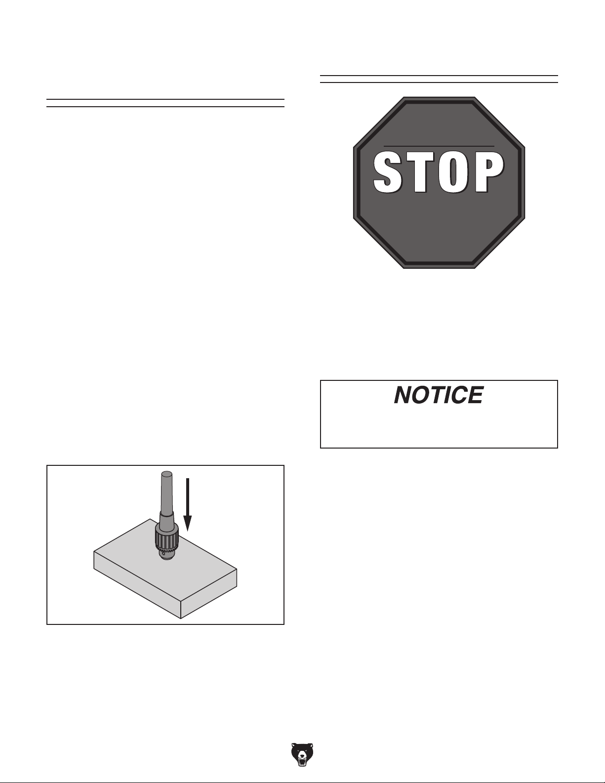
Arbor/Chuck
An arbor is included for the drill chuck that
comes with this machine. The following procedure
describes how to install the arbor in the chuck.
After the arbor is installed in the drill chuck, it
is very difficult to separate the assembly. If you
would like to use a different chuck in the future,
we recommend obtaining a new arbor.
IMPORTANT: DO NOT
and arbor assembly
AFTER
the test run.
To join drill chuck and arbor:
1.
clean drill
2.
3.
4.
5. Attempt to separate drill chuck and arbor by
hand —if they separate, repeat Steps 3–4.
Assembly
install the drill chuck
into the spindle until
Use acetone or lacquer thinner to
chuck and arbor mating surfaces, especially
the bore.
Retract chuck jaws completely into chuck.
Verifying Lubrication
GEARBOX MUST
BE FILLED WITH OIL!
OIL MAY NOT BE
SHIPPED WITH MACHINE!
Refer to Lubrication Section
for Correct Oil Type.
This machine was shipped from the factory with
oil in it, but the headstock and column oil reservoir
levels must be verified before the mill is operated
for the first time. Refer to the Lubrication section, beginning on Page 45, for details on how to
check oil.
Insert small end of arbor into chuck.
Hold assembly by the arbor and tap chuck
onto a block of wood with medium force, as
illustrated below.
Figure 18. Arbor/chuck assembly.
Damage caused by running mill without
oil in reservoir will not be covered under
warranty.
-22-
Model G0827 (Mfd. Since 11/17)
Page 25

Assembly
The machine must be fully assembled before it
can be operated. Before beginning the assembly
process, refer to
all
goes smoothly, first clean any
ered or coated in heavy-duty rust preventative (if
applicable).
Needed for Setup and gather
listed items. To ensure the assembly process
parts that are cov-
Your machine comes from the factory mostly
assembled. To complete assembly you must
install:
2. Slide Z-axis crank onto square end
(see Figure 20).
Square
End
Figure 20. Location of square spindle.
• X-Axis handwheel handle
• Y-Axis handwheel handle
• Z-Axis crank
• Coarse downfeed handles
• Fine downfeed handwheel handle
To assemble mill:
Install handwheel handles onto X-axis and
1.
Y-axis handwheels (see Figure 19).
X-Axis
Handwheel
Y-Axis
Handwheel
3. Thread coarse downfeed handles into coarse
downfeed hub (see Figure 21).
4. Remove fine downfeed handle from rear of
fine downfeed handwheel and thread into
front of handwheel (see Figure 21).
Fine
Downfeed
Handwheel
Handle
Coarse
Downfeed Handle
Figure 21. Downfeed components assembled.
Figure 19. Locations of X-axis and Y-axis
handwheels.
Model G0827 (Mfd. Since 11/17)
-23-
Page 26
Power Connection
DO NOT start machine until all preceding
setup instructions have been performed.
Operating an improperly set up machine
Serious injury or death can result from
Electrocution or fire can occur
if machine is ungrounded,
incorrectly connected to
power, or connected to an
undersized circuit. Use an
electrician or a qualified service personnel to ensure a
safe power connection.
Before the machine can be connected to the
power supply, there must be an electrical circuit that meets the Circuit Requirements on
Page 14, and the correct plug must be installed
according to the instructions and wiring diagrams
provided by the plug manufacturer.
If the plug manufacturer did not include instructions, the wiring of a generic NEMA 15 -15 plug is
illustrated in the Wiring section on Page 64.
Test Run
Once assembly is complete, test run the machine
to ensure it is properly connected to power and
safety components function properly.
If you find an unusual problem during the test run,
immediately stop the machine, disconnect it from
power, and fix the problem BEFORE operating the
machine again. The Troubleshooting table in the
SERVICE section of this manual can help.
using this machine BEFORE understanding
its controls and related safety information.
DO NOT operate, or allow others to operate,
machine until the information is understood.
To minimize the risk of electrocution, fire, or equipment damage, installation work and electrical wiring MUST be done by an electrician or qualified
service personnel.
Note About Extension Cords: Using an incor-
rectly sized extension cord may decrease the
life of electrical components on your machine.
Refer to Extension Cords on Page 15 for more
information.
Note About Phase Converters: Avoid using a
static phase converter to supply 3-Phase power
for this machine, as it could damage or decrease
the life of sensitive electrical components. If you
must use a phase converter, only use a rotary
phase converter that is sized at least 50% larger
than the highest HP rating of this machine. If
using a phase converter to supply power, only
connect the manufactured leg or "wild wire" to the
L2 terminal (see location on Page 67). The L2
terminal can handle power fluctuations because it
is wired directly to the motor.
may result in malfunction or unexpected results that can lead to serious injury,
death, or machine/property damage.
The test run consists of verifying following:
• Vertical spindle motor runs correctly
• Vertical spindle turns forward (clockwise)
when viewed from top of headstock
• Horizontal spindle motor runs correctly
• E-STOP button and rear column cover safety
switch work correctly
• Lamp works correctly
• Coolant system works correctly
• Power feed units work correctly
-24-
Model G0827 (Mfd. Since 11/17)
Page 27

Mill Test Run
1. Clear all setup tools away from machine.
Set vertical spindle to 140 RPM (see Page 36
2.
for details on how to change speeds).
Push E-STOP button (see Figure 22) to
3.
avoid unexpected start up when machine is
connected to power.
E-STOP Button
Figure 22. Location of E-STOP button.
4. Connect mill to power supply specified in
POWER SUPPLY on Page 14.
7. Press POWER button (see Figure 24) on
control panel to enable power to machine—
power button should illuminate.
Press FORWARD button (see Figure 24) for
8.
(vertical spindle).
FORWARD
Button
(Vertical
Spindle)
POWER
Button
Figure 24. Location of vertical spindle
FORWARD button and POWER button.
9.
Listen for abnormal noises and watch for
anything unexpected from mill. It should run
smoothly and without excessive vibration or
rubbing noises.
Turn master power switch ON (see Figure 23).
5.
Master
Power
Switch
Figure 23. Location of master power switch.
Twist E-STOP button clockwise until it pops
6.
out—this resets it and allows mill to operate.
— Strange or unusual noises or actions
must be investigated immediately. Turn
machine OFF and disconnect it from the
power source before investigating or correcting potential problems.
Model G0827 (Mfd. Since 11/17)
-25-
Page 28

Verify vertical spindle rotates forward (clock-
10.
wise looking down on headstock).
12. Repeat Steps 8–11 with vertical spindle
reverse rotation.
— If spindle rotates in wrong direction, stop
machine and DISCONNECT FROM
POWER! Phase of incoming power supply
is reversed. Open electrical panel door,
swap wires at "L1" and "L3" terminals (see
Figure 25), then close panel and reconnect machine to power.
Electrical
Panel
Door
L1
Terminal
L3
Terminal
Set horizontal spindle to 48 RPM (see Page 36
13.
for details on how to change speeds).
Repeat Steps 8–12 with horizontal spindle.
14.
Press E-STOP button on control panel.
15.
16. WITHOUT resetting E-STOP button, attempt
to start vertical spindle rotation. Machine
should not start.
— If machine does not start, E-STOP button
safety feature is working correctly.
— If machine does start (with the E-STOP
button pushed in), immediately disconnect
power to the machine. The E-STOP button safety feature is not working correctly.
This safety feature must work properly
before proceeding with regular operations.
Review Troubleshooting on Page 55.
17. Loosen hex bolt shown in Figure 27 and
open rear column cover.
Figure 25. Location of L1 and L3 terminals
inside electrical panel.
11. Press STOP button (vertical spindle) shown
in Figure 26 and wait for spindle to completely stop.
STOP Button
(Vertical
Spindle)
Rear Column
Cover
Figure 27. Location of bolt for opening rear
column cover.
Figure 26. Location of vertical spindle STOP
button.
-26-
Model G0827 (Mfd. Since 11/17)
Page 29
18. Reset E-STOP button.
19. WITHOUT closing rear column cover, press
POWER button. Indicator light should not
illuminate. Attempt to start vertical spindle
rotation. Machine should not start.
— If machine does not start, rear column
cover safety switch is working correctly.
Power Feed Test Run
The mill comes with power feed units for X- and
Y-axis table travel. Proper operation of the limit
switches is critical for the safe use of the power
feed units. If the power feeds do not operate as
expected during the following steps, disconnect
machine from power and review Troubleshooting
table on Page 55.
— If machine does start (with the rear col-
umn cover open), immediately disconnect
power to machine. The rear column cover
switch safety is not working correctly.
This safety feature must work properly
before proceeding with regular operations.
Review Troubleshooting on Page 55.
20. Close rear column cover and fully tighten
bolt.
Ensure LED work light functions properly.
21.
Press POWER button.
22.
Coolant must be added before the coolant
pump is tested. Otherwise, running pump
without coolant will burn it up.
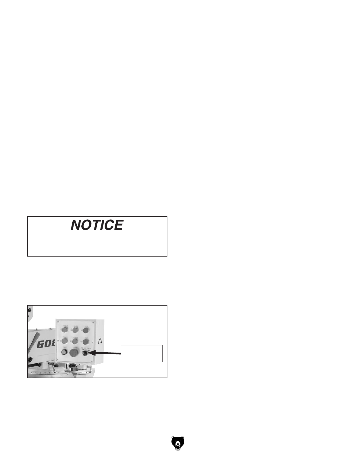
23. Use coolant pump switch on control panel to
start pump (see Figure 28), then open nozzle
valve. Verify that coolant flows from nozzle,
then turn pump OFF.
To test power feeds:
Make sure all tools, cables, and other items
1.
are well clear of table movement as you follow these steps.
Refer to X- and Y-axis Power Feed identifi-
2.
cation on Page 7 to understand how power
feeds, table locks, and limit switches function.
Loosen X-axis table locks on front of table.
3.
4. Make sure X-axis power feed directional lever
is in neutral (middle) position, turn speed dial
counterclockwise to lowest setting, then turn
power feed ON.
Move direction knob to left, slowly rotate
5.
speed dial clockwise to increase speed, then
confirm table is moving left.
Watch for table limit stop to press against
6.
limit switch plunger and turn power feed OFF,
stopping table movement.
Move direction knob through neutral (middle)
7.
position and all the way right. Table should
begin moving right.
Coolant
Pump Switch
Figure 28. Location of coolant pump switch.
Model G0827 (Mfd. Since 11/17)
Confirm table stops moving when limit stop
8.
presses against limit switch plunger.
Move direction knob to neutral (middle) posi-
9.
tion, turn speed dial counterclockwise to lowest setting, and turn power feed OFF.
Repeat Steps 3–9 in a similar manner for the
10.
Y-axis power feed.
Congratulations! The Test Run of the mill is
complete. Continue to the next page to perform the Spindle Break-In and Inspections &
Adjustments procedures.
-27-
Page 30
Spindle Break-In
The spindle break-in procedure distributes lubrication
reduce the risk
of early
if there are any "dry" spots
or areas where lubrication has settled in the bearings. You
efore
placing
for the
first time when the machine is new or if it has
been sitting idle for longer than 6 months.
Always start the spindle break-in at the lowest
speed to minimize wear if there
Allow the spindle to run long enough to warm up
and distribute the bearing grease, then incrementally increase spindle speeds and repeat this process at each speed until reaching the maximum
spindle speed. Following the break-in procedure
in this progressive manner helps minimize any
potential wear that could occur before lubrication
is fully distributed.
Horizontal Spindle Break-In
1. Run horizontal spindle at 48 RPM for 10
minutes (see Page 37 for details on how to
change speeds).
throughout the bearings to
bearing failure
must complete this procedure b
operational loads on the spindle
are dry spots.
Complete spindle bearing break-in procedure to prevent rapid wear and tear of
spindle components once mill is placed into
operation.
2. Reverse spindle rotation direction and run
spindle for an additional 10 minutes.
3. Run spindle for 5 minutes in each direction of
spindle rotation for all 11 remaining spindle
speeds, progressively increasing in RPM to
highest speed.
Congratulations! Spindle Break-In is complete.
We recommend changing the headstock oil
before operating the machine further (refer to
Lubrication on Page 45).
Inspections &
Adjustments
The following list of adjustments were performed
at the factory before the machine was shipped:
• X-Axis Leadscrew Backlash ........... Page 60
• Gib Adjustments ..............................Page 61
DO NOT perform this procedure independently of Test Run section. Mill could be
seriously damaged if controls are set differently than instructed in that section.
Vertical Spindle Break-In
1. Run vertical spindle at 140 RPM for 10
minutes (see Page 36 for details on how to
change speeds).
2. Reverse spindle rotation direction and run
spindle for an additional 10 minutes.
3. Run spindle for 5 minutes in each direction
of spindle rotation for all seven remaining
spindle speeds, progressively increasing in
RPM to highest speed.
-28-
Be aware that machine components can shift
during the shipping process. Pay careful attention
to these adjustments during machine operation.
If adjustments are not set per procedures in this
manual or personal preferences, re-adjust them.
Since the head has been moved around for
shipping purposes, you will need to tram it
so that the spindle is perpendicular to the
table. Refer to the Tramming Mill Head section on Page 58 for detailed instructions.
During first 16 hours of use, V-belts will
stretch and seat into pulley grooves. V-belts
must be properly tensioned after this period to ensure proper power transmission
and avoid reducing life of belts. Refer to
Tensioning/Replacing V-Belts on Page 53.
Model G0827 (Mfd. Since 11/17)
Page 31
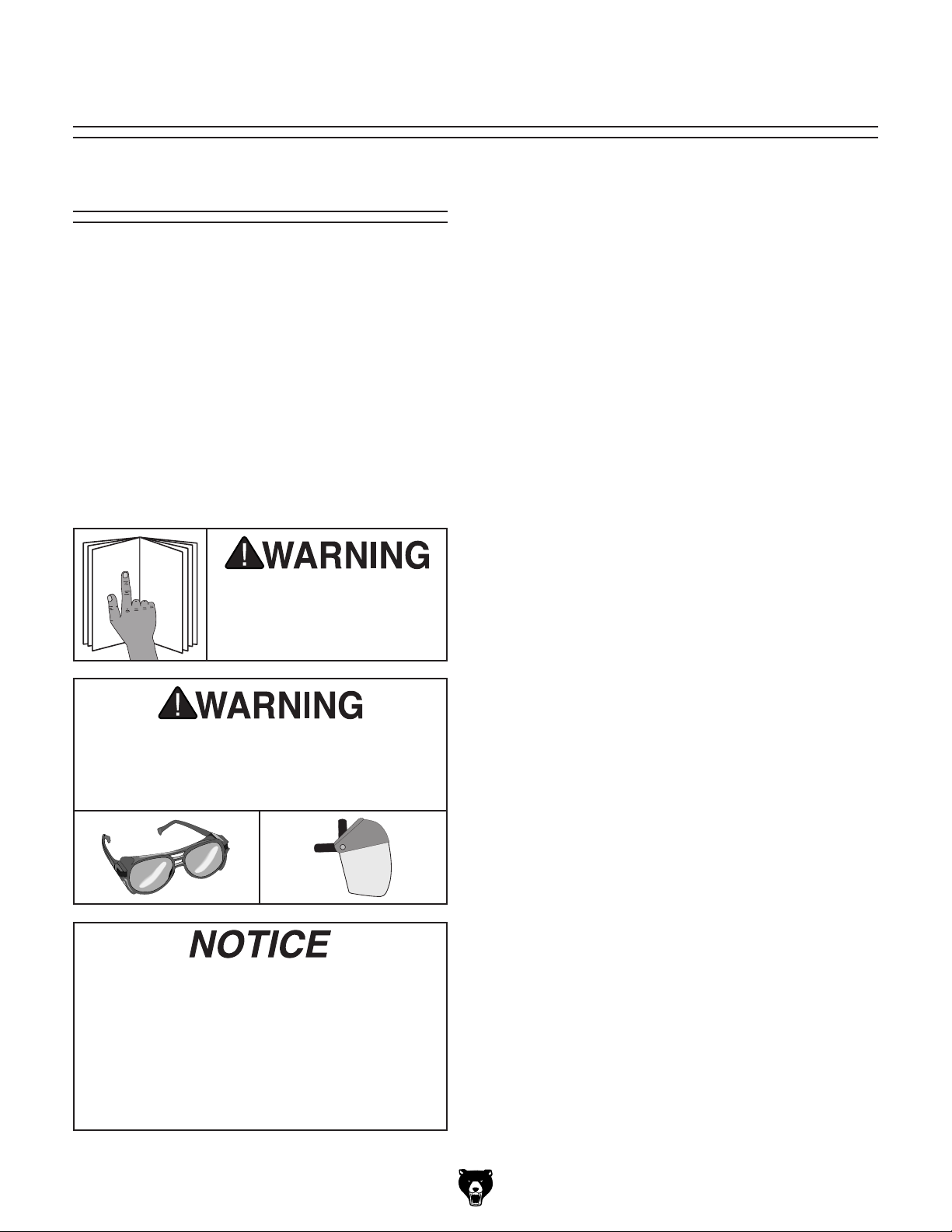
SECTION 4: OPERATIONS
The purpose of this overview is to provide the novice machine operator with a basic understanding
of how the machine is used during operation, so
the
discussed later
in this manual
Due to the generic nature of this overview, it is
not intended to be an instructional guide. To learn
more about specific operations, read this entire
manual,
training from experienced
machine operators
outside of this manual by reading "how-to" books,
trade magazines, or websites.
To reduce your risk of
serious injury, read this
entire manual BEFORE
Operation Overview
machine controls/components
are easier to understand.
seek additional
, and do additional research
To complete a typical operation, the operator
does the following:
Examines workpiece to make sure it is suit-
1.
able for operation.
Firmly clamps workpiece to table or a mill
2.
vise securely mounted to table.
Installs correct cutting tool for operation.
3.
4. Uses downfeed and table controls to correctly
position cutting tool and workpiece for operation. If X- or Y-axis power feed will be used
during operation, operator confirms speed
and length of table movement required.
Configures machine for correct spindle speed
5.
of operation.
using machine.
To reduce risk of eye or face injury from
flying chips, always wear approved safety
glasses and a face shield when operating
this machine.
If you are not experienced with this type
of machine, WE STRONGLY RECOMMEND
that you seek additional training outside of
this manual. Read books/magazines or get
formal training before beginning any projects. Regardless of the content in this section, Grizzly Industrial will not be held liable
for accidents caused by lack of training.
Model G0827 (Mfd. Since 11/17)
Puts on personal protective equipment, and
6.
makes sure workpiece and table are clear of
all tools, cords, and other items.
Turns machine ON, then starts spindle rota-
7.
tion and performs operation.
Turns machine OFF.
8.
-29-
Page 32

Table Movement
The table travels in three directions, as illustrated
in Figure 29.
These movements are controlled by table
handwheels and the Z-axis crank. Additionally,
the table can be moved along the X- or Y-axis with
the power feed units.
X-Axis or Longitudinal Travel
(Left & Right)
Table Locks
Use table locks to increase the rigidity of the table
when movement of that axis is not required for the
operation.
Refer to Figure 31 to identify the locks for each
table axis.
Limit Stops
Use limit stops in conjunction with the power feed
units to set the total amount of travel. The limit
stops come into contact with the limit switches
and stop power feed motion.
Y-Axis or
Cross Travel
(In & Out)
Z-Axis or
Vertical Elevation
(Up & Down)
Figure 29. The directions of table movement.
Graduated Index Rings
The table handwheels and Z-axis crank have
graduated rings (see Figure 30) that are used to
determine table movement in 0.001" increments
with one full revolution equaling 0.200" of travel.
Additionally, the left X-axis handwheel and Z-axis
crank each have a thumbscrew that is used to
adjust the dial to "0."
Refer to Figure 31–32 to identify the X- and
Y-axis limit stops.
X-Axis Locks
Z-Axis
X-Axis Limit
Stops
Figure 31. Locations of table locks.
Y-Axis Limit Switch
Y-Axis
Locks
X-Axis Limit
Stops
Lock
Lever
Graduated
Rings
Figure 30. Locations of graduated rings.
-30-
X-Axis Limit
Switch
Y-Axis Limit Stops
Figure 32. Locations of limit switches.
Always keep table locked in place unless
table movement is required for your operation. Unexpected table and workpiece
movement could cause tooling to bind with
workpiece, which may damage tooling or
workpiece.
Model G0827 (Mfd. Since 11/17)
Page 33

Head Tilt Ram Movement
Head Tilt (Left/Right) ...................................90°
When positioning head back to 0° after
tilting it, you will need to tram it to make
certain spindle is precisely perpendicular
to table to ensure proper milling accuracy.
Refer to Tramming Mill Head section on
Page 58 for detailed instructions.
Items Needed Qty
Open-End Wrench 19mm .................................. 1
Open-End Wrench 24mm
Additional Person
To tilt head:
DISCONNECT MACHINE FROM POWER!
1.
2. Loosen (3) hex nuts (one on each side of
head and one underneath) that secure head
to ram (see Figure 33).
.............................................. 1
.................................. 1
Ram Travel
Turret or Column Swivel (Left/Right)
Tools Needed Qty
Knee Crank or Open-End Wrench 14mm ......... 1
Open-End Wrench 24mm
....................................................18"
....... 180°
.................................. 1
Moving Ram Forward/Backward
1. DISCONNECT MACHINE FROM POWER!
2. Loosen both lock handles shown in Figure 34.
Rotate pinion gear bolt (see Figure 34) to
3.
move ram until spindle is in desired position.
Ram Lock Handles
Angle
Scale
Tilting
Bolt
Hex Nut
(1 of 3)
Figure 33. Head tilting controls.
With assistance from another person to sup-
3.
port head, rotate tilting bolt until head is in
desired position.
Note: Use angle scale shown in Figure 35 as
a guide for setting tilt angle.
Retighten hex nuts securing head to ram
4.
before resuming operation.
Pinion Gear Bolt
Figure 34. Ram movement controls.
Retighten lock handles to secure ram move-
4.
ment before resuming operation.
Angle
Scale
Tilting
Bolt
Hex Nut
(1 of 3)
Figure 35. Head tilting controls.
Model G0827 (Mfd. Since 11/17)
-31-
Page 34

Rotating Ram on Turret
1. DISCONNECT MACHINE FROM POWER!
2. Loosen (4) hex nuts (two on each side of ram)
that secure ram to turret (see Figure 36).
Horizontal
Arbor Support
Hex Nuts
(2 of 4)
Installing/Removing
Tooling
Vertical Spindle
Tooling is held in the vertical spindle by a combination of the R8 taper, a pin inside the spindle,
and a
The Model G0827 includes the following vertical
spindle tools (see Figure 39):
A. B16 Drill Chuck w/R8–B16 Arbor. Refer to
B
7
⁄16"-20 drawbar.
Arbor/Chuck Assembly on Page 22.
. R8–MT#3 Spindle Sleeve. Used for MT#3
tools and will accommodate tools with a tang.
It also has a drift key slot for tool removal.
Figure 36. Ram rotation hex nuts.
3. Make sure cables and hoses do not get
entangled or stretched, and that work lamp
and DRO are clear of rotation path as you
move ram on turret.
— If rotating ram 180 degrees, horizontal
arbor support must be removed to provide clearance for control panel and DRO
(see Figure 36).
Retighten (4) hex nuts that secure ram on tur-
4.
ret before resuming operation.
. MT#3–MT#2 Spindle Sleeve. Used for MT#2
C
tools and will accommodate tools with a tang.
It also has a drift key slot for tool removal.
. R8–1" End Mill Arbor. Arbor accepts 1" bore
D
mill cutters.
E. Drift Key: Use for tool removal.
A
B
Drift Key Slot
Tang
C
D
E
-32-
Figure 37. Vertical spindle tools included with
Model G0827.
Model G0827 (Mfd. Since 11/17)
Page 35

Tools Needed Qty
Open-End Wrench 19mm .................................. 1
Brass Hammer
Heavy Leather Gloves
Shop Rags
.................................................. 1
................................ 1 Pair
......................................... As Needed
Installing Vertical Spindle Tooling
1. DISCONNECT MACHINE FROM POWER!
2. Clean any debris or surface substances from
inside spindle taper and mating surface of
tooling.
Note: Debris or oily substances can prevent
tooling and spindle from properly mating. This
condition can cause excessive vibration, poor
cutting results, or tool/workpiece damage.
Align tooling keyway with pin inside spindle
3.
taper, then firmly push tooling into spindle to
seat it.
With one hand holding tooling in place, insert
4.
vertical drawbar (longer of two drawbars) into
spindle from top of head, then thread it into
tooling (see Figure 38).
Note: Drawbar has an adjustment hex nut
(see Figure 38) that is used to raise/lower
drawbar to compensate for different tooling
lengths.
Vertical
Drawbar
Adjustment
Hex Nut
Cutting tools are sharp and can easily
cause laceration injuries. Use heavy leather
gloves or shop rags to protect your hands
when handling cutting tools.
Figure 38. Vertical drawbar inserted in spindle.
Tighten drawbar until it is snug. Avoid over-
5.
tightening, as this could make removing tooling difficult later.
Removing Vertical Spindle Tooling
1. DISCONNECT MACHINE FROM POWER!
Note: Make sure drawbar has at least three
threads engaged with tooling in next step to
avoid damaging drawbar threads or tool.
Loosen drawbar a couple of turns, then tap
2.
top of it with a brass hammer to knock taper
between spindle and tooling loose.
Support tooling with one hand, then com-
3.
pletely unthread drawbar from tooling.
Model G0827 (Mfd. Since 11/17)
-33-
Page 36

Installing Horizontal Spindle &
Tooling
Single or multiple cutters (gang milling) can be
arranged anywhere along the length of the arbor
for simple to very complex cutting operations.
The Model G0827 includes the following horizontal spindle tools (see Figure 39):
To install horizontal tooling:
DISCONNECT MACHINE FROM POWER!
1.
2. Loosen locking bolt on side of arbor sup-
port, and slide support off ram dovetail way
(see Figure 40).
A. 1 1⁄4" Dia. Horizontal Arbor w/Spacers. Used
for horizontal milling operations with 1
cutters.
B. 1" Dia. Horizontal Arbor w/Spacers. Used
for horizontal milling operations with 1" bore
cutters.
A
B
Figure 39. Horizontal arbors included with
G0827.
Tools Needed Qty
Open-End Wrench 19mm .................................. 1
Open-End Wrenches 24mm
Open-End Wrench 32mm
Brass Hammer
.................................................. 1
.............................. 2
.................................. 1
1
⁄4" bore
Locking Bolt
Figure 40. Horizontal arbor support, locking bolt,
and ram rotation hex nut locations.
Loosen ram rotation hex nuts (see Figure
3.
40), then rotate ram 180°, as shown in
Figure 41.
Note: Make sure "0" marks on ram base and
angle scale are aligned and four ram rotation
hex nuts are retightened.
Arbor
Ram Rotation
Hex Nuts (2 of 4)
Horizontal
Arbor Support
-34-
Horizontal
Spindle
Figure 41. Horizontal arbor seated in spindle
with ram fully extended and rotated 180 degrees.
Model G0827 (Mfd. Since 11/17)
Page 37

4. Extend ram all the way forward.
5. Clean any debris or surface substances from
inside spindle taper and mating surface of
arbor.
Align keyway of arbor with protruding pin
6.
inside spindle taper, then firmly push arbor
into spindle to seat it (see Figure 41).
11. Secure arbor support by retightening support
locking bolt.
Secure arbor assembly with right-hand arbor
12.
nut (see Figure 42).
Removing Horizontal Spindle Tooling
1.
DISCONNECT MACHINE FROM POWER!
With one hand holding arbor in place, insert
7.
horizontal drawbar (shorter of two drawbars)
into spindle from rear of column, then thread
it into arbor.
Tighten drawbar until it is snug. Avoid over-
8.
tightening, as this could make removing arbor
difficult later.
Cutting tools are sharp and can easily
cause laceration injuries. Use heavy leather
gloves or shop rags to protect your hands
when handling cutting tools.
Add ISO 32 oil or equivalent to horizontal
9.
spindle and arbor support ball oilers (refer to
Ball Oilers, beginning on Page 47).
Install cutter(s) and spacers on arbor in such
10.
a way that last spacer is inside brass bushing
and arbor threads are fully exposed as you
slide arbor support back onto ram dovetail
ways (see Figure 42).
2. Remove arbor nut from arbor, then remove
arbor support from ram dovetail ways.
Note: Make sure drawbar has at least three
threads engaged with arbor in next step to
avoid damaging drawbar threads or arbor.
Loosen drawbar a couple of turns. Then tap
3.
end of drawbar with a brass hammer to knock
taper loose between spindle and arbor.
Support arbor with one hand, then completely
4.
unthread drawbar from arbor.
5. Remove arbor.
Re-install arbor support and properly position
6.
and secure ram for next operation.
Brass
Bushing
Tooling
Right-Hand
Arbor Nut
Figure 42. Horizontal arbor and cutter installed.
Model G0827 (Mfd. Since 11/17)
-35-
Page 38

Spindle Speed
Using the correct spindle speed is important for
safe and satisfactory results, as well as maximizing tool life.
To set the spindle speed for your operation, you
will need to: (1) Determine the best spindle speed
for the cutting task, and (2) configure the mill controls to match the closest spindle speed.
Determining Spindle Speed
Many variables affect the optimum spindle speed
to use for any given operation, but the two most
important are the recommended cutting speed for
the workpiece material and the diameter of the
cutting tool, as noted in Figure 43:
Recommended
*
Cutting Speed (FPM) x 12
Tool Diameter (in inches) x 3.14
= RPM
Cutting Speeds for High Speed Steel (HSS)
Cutting Tools
Workpiece Material Cutting Speed (sfm)
Aluminum & Aluminum Alloys 300
Brass & Bronze 150
Copper 100
Cast Iron, soft 80
Cast Iron, hard 50
Mild Steel 90
Cast Steel 80
Alloy Steel, hard 40
Tool Steel 50
Stainless Steel 60
Titanium 50
Plastics 300-800
Wood 300-500
Note: For carbide cutting tools, double the cut-
ting speed. These values are a guideline only.
Refer to the MACHINERY'S HANDBOOK for
more detailed information.
Figure 44. Cutting speed table.
*
Double if using carbide cutting tool
Figure 43. Spindle speed formula for milling.
Cutting speed, typically defined in feet per minute
(FPM), is the speed at which the edge of a tool
moves across the material surface.
A recommended cutting speed is an ideal speed
for cutting a type of material in order to produce
the desired finish and optimize tool life.
The books Machinery’s Handbook or Machine
Shop Practice, and some internet sites, provide excellent recommendations for which cutting
speeds to use when calculating the spindle speed.
These sources also provide a wealth of additional
information about the variables that affect cutting
speed and are a good educational resource.
Also, there are a large number of easy-to-use
spindle speed calculators that can be found on
the internet. These sources will help you take into
account all applicable variables to determine the
best spindle speed for the operation.
To avoid damaging spindle, gears, or cutting
tools when setting spindle speed range:
• Spindle rotation must be turned OFF and
spindle must be at complete stop BEFORE
you change spindle speed range.
• To avoid damaging moving parts inside
headstock, never start spindle rotation
without speed selector detent pins firmly
seated in correct position.
-36-
Model G0827 (Mfd. Since 11/17)
Page 39

Setting Vertical Spindle Speed
Use the charts below (see Figure 45) or those on
the headstock when setting the spindle speed.
With the spindle completely stopped, position the
high/low range selector (see Figure 46) and spindle speed selectors (see Figure 47) as indicated
by the spindle speed chart to set the desired
spindle RPM. Position I on the range selector is
low speed range; position II is high speed range.
Note: If necessary, rotate the spindle a little by
hand to mesh the gears when changing speeds.
Low Range (I)
Setting Horizontal Spindle Speed
Use the chart below (see Figure 48) or the one
on the rear column cover when setting the spindle
speed. With the spindle completely stopped, position the range knob and spindle speed knobs (see
Figure 49), as indicated by the spindle speed
chart, to set the desired spindle RPM.
Note: If necessary, rotate the spindle a little by
hand to mesh the gears when changing speeds.
Spindle Speed KnobsRange
Knob
BA
Spindle
Speed
Selectors
Figure 45. Vertical spindle speed charts.
High/Low
Range
Selector
Figure 46. Location of high/low range selector.
High Range (II)
Low Range
(I)
High/Low
Range
Selector
High
Range
(II)
C
I
II
III
Figure 48. Horizontal spindle speed chart.
48
72
96
Spindle Speed Knobs
132 324
180
Range Knob
CD D
456
612240
1140
1560
816
Spindle Speed Selectors
Figure 47. Location of spindle speed selectors.
Model G0827 (Mfd. Since 11/17)
Figure 49. Location of horizontal spindle speed
and range knobs.
-37-
Page 40

Using Spindle
Downfeed Controls
Use Figure 50 and the descriptions below to
understand the downfeed components that control the spindle downfeed travel.
Fine
Downfeed
Handwheel
Quill
Lock
Coarse
Downfeed
Lever
Selection
Lever
Coarse Downfeed
When the coarse downfeed is engaged, pull the
coarse downfeed levers down to lower the spindle. An internal coil spring helps raise the spindle
up when you stop applying downward pressure
on the lever.
Note: To maintain control of the upward spindle
travel and the rotating bit in your workpiece,
always continue holding the lever until the spindle
returns to the top position. Letting go of the coarse
downfeed levers when the spindle is in the lowered position will cause the spindle to retract too
quickly and slam up into the headstock or lift the
workpiece and cause it to spin out of control.
The coarse downfeed hub features a graduated
dial that measures spindle movement in 1" increments, with one full revolution equaling 5" of
spindle travel. The dial has a thumbscrew that is
used to adjust the dial to "0".
Figure 50. Spindle downfeed controls.
Coarse Downfeed Levers: Allow you to manu-
ally control downfeed travel of spindle in a rapid
manner. The spindle automatically returns to the
top position when pressure is released from the
handle, making this ideal for drilling operations.
Fine Downfeed Handwheel: Manually controls
downfeed travel in a slow, precise manner. Unlike
coarse downfeed, the spindle does not automatically retract, which makes this ideal for fine positioning of the spindle/cutter for miling operations.
The attached graduated dial has increments of
0.001" with one full revolution representing 0.100"
of travel.
Selection Lever: When tightened, enables the
fine downfeed handwheel; conversely, when loosened enables the coarse downfeed levers.
Quill Lock: Secures the quill in place for increased
stability during milling operations. Typically only
used after first positioning spindle/cutter with fine
downfeed handwheel.
-38-
Model G0827 (Mfd. Since 11/17)
Page 41

Fine Downfeed
When the fine downfeed is engaged, the spindle
only moves up or down when the handwheel
(see Figure 51) is rotated (there is no automatic
spindle return to the top position, as with the
coarse downfeed controls). This level of control
allows the spindle height to be locked in place
with the quill lock when milling a flat surface
across the face of a workpiece.
Note: The graduated dial on the fine downfeed
handle measures spindle movement in 0.001"
increments, with one full revolution equaling 0.100"
of spindle travel. The dial has a thumbscrew that
is used to adjust the dial to "0".
Using Fine Downfeed Controls
In the following example, the fine downfeed
controls are used to mill 0.010" off a workpiece:
Use Z-axis crank to adjust workpiece surface
1.
just below cutting tool, then secure the headstock with Z-axis lock lever.
2.
Tighten selection lever (see Figure 51) to
engage fine downfeed handwheel.
Loosen quill lock.
3.
4. Rotate fine downfeed handwheel clockwise
and lower cutting tool so it just touches
workpiece.
Fine
Downfeed
Handwheel
Quill
Lock
Thumbscrew
Figure 51. Fine downfeed controls.
Selection
Lever
Move workpiece out of the way.
5.
6. Using graduated dial to gauge spindle move-
ment, rotate fine downfeed handwheel clockwise 0.010".
Tighten quill lock.
7.
8. Turn mill ON and perform cutting pass.
Model G0827 (Mfd. Since 11/17)
-39-
Page 42
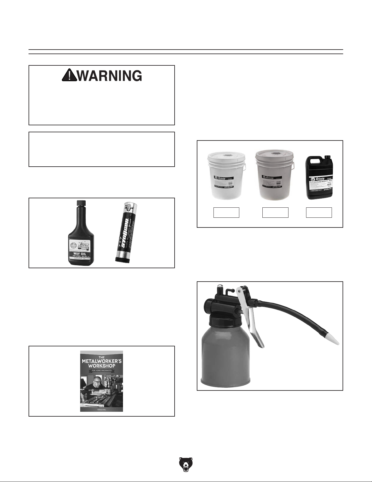
SECTION 5: ACCESSORIES
Installing unapproved accessories may
order online at www.grizzly.com or call 1-800-523-4777
cause machine to malfunction, resulting in
serious personal injury or machine damage.
To reduce this risk, only install accessories
recommended for this machine by Grizzly.
NOTICE
Refer to our website or latest catalog for
additional recommended accessories.
SB1365—South Bend Way Oil ISO-68
T26419—Syn–O–Gen Synthetic Grease
T23962—ISO-68 Moly-D Way Oil, 5 Gal.
T23963—ISO-32 Moly-D Machine Oil, 5 Gal.
T26685—ISO-32 Moly-D Machine Oil, 1 Gal.
Moly-D oils are some of the best we've found for
maintaining the critical components of machinery
because they tend to resist run-off and maintain
their lubricity under a variety of conditions—as
well as reduce chatter or slip. Buy in bulk and
save with 1- or 5-gallon quantities.
T23962 T23963 T26685
Figure 52. Recommended products for machine
lubrication.
T25614—The Metalworker's Workshop for
Home Machinists
This book presents a complete guide to creating
a workshop space and then equipping it to serve
a wide range of metalworking activities. Softcover,
152 pages.
Figure 54. ISO-68 and ISO-32 machine oil.
H7617—Oil Can w/Plastic Nozzle
This high-pressure oil can is perfect for lubricating
the ball oilers found on your machine. Each can
holds 5 ounces of oil.
Figure 55.
H7617 High-Pressure Oil Can.
Figure 53. T25614 Metalworker's Workshop for
Home Machinists book.
-40-
Model G0827 (Mfd. Since 11/17)
Page 43

order online at www.grizzly.com or call 1-800-523-4777
G1076—58-Pc. Clamping Kit
This clamping kit includes 24 studs, 6 step block
pairs, 6 T-nuts, 6 flange nuts, 4 coupling nuts, and
6 end hold-downs. The rack is slotted so it can be
mounted close to the machine for easy access.
Made for
5
⁄8" T-slots.
Figure 56. G1076 Clamping Kit.
T10168 —3" Boring Head Set
This all-inclusive set features a precision 3" bor-
3
ing head, R8 shank, five-piece set of
tipped boring bars, five-piece set of
1
ing bars,
⁄2 " to 3⁄4" adapter, wrenches, and fitted
⁄4" carbide-
1
⁄2 " HSS bor-
case.
T25702—5-Pc. R8 End Mill Holder Set
Hold various sized end mills in your R8 spindle
with this End Mill Holder Set. Includes holders for
3
⁄16", 3⁄8", 1⁄2 ", 5⁄8", and 3⁄4" end mills.
Figure 58. T25702 5-Pc. R8 End Mill Holder Set.
®
SB1348—South Bend
SB1349—South Bend
Get true South Bend
8-Pc. R8 Collet Set
®
16-Pc. R8 Collet Set
®
quality and precision with
one of these Quick-Change Collet Sets. Each set
includes hardened and precision-ground spring
collets for maximum holding power, collet chuck,
spanner wrench, and protective moulded case.
Figure 57. T10168 3" Boring Head Set.
Figure 59. Model SB1349 South Bend 16-Pc.
R-8 Collet Set.
Model G0827 (Mfd. Since 11/17)
-41-
Page 44

order online at www.grizzly.com or call 1-800-523-4777
T24800—1-2-3 Blocks
T24799—2-4-6 Blocks
Blocks are square to within .0003". Measure 1" x
1
2" x 3". Parallel set measures 6" long by
3
⁄4", 7⁄8", 1", 11⁄8", 11⁄4", 13⁄8", 11⁄2 ", and 15⁄8".
⁄2 ", 5⁄8",
Figure 60. 1-2-3 Blocks and 2-4-6 Blocks.
G7156—4" (3 5⁄8") Precision Milling Vise
G7154—5" (4 1⁄2") Precision Milling Vise
G7155—6" (5 5⁄8") Precision Milling Vise
Swiveling Milling Vises feature perfectly aligned,
®
precision-ground jaws, large Acme
screws and
easy to read 0°–360° scales.
G9612—Test Indicator
This Test Indicator has a 0.03" range in graduations of 0.0005", an easy-to-read dial, and a
pivoting stylus that moves at right angles to the
dial face.
Figure 61. G9612 Test Indicator.
Tilt Tables
G5758—5" x 7" x 3 3⁄4"
G5759—7" x 10" x 5"
Set your work at any angle from -45° to +45° with
these sturdy Tilt Tables. Heavy-duty construction
7
includes
cision base.
⁄16" T-slots, two locking screws, and pre-
1
⁄2 " mounting slots.
Figure 63. Precision Milling Vise.
H7527— 6" Rotary Table w/ Div. Plates
Use this 6" rotary table in either the horizontal
or vertical position for a variety of milling applications, and with the set of dividing plates and
adjustable tailstock, your milling applications are
nearly unlimited. With 4-degree table movement
per handle rotation and 20 second vernier scale,
control is very accurate and precise. Also includes
3
⁄8" clamping set for the 4-slot table. Everything
a
you need in one great set!
Figure 64. H7527 6" Rotary Table w/Div. Plates.
Figure 62. G5758 Tilt Table.
-42-
Model G0827 (Mfd. Since 11/17)
Page 45

G9756—20-Pc. HSS End Mill Set
order online at www.grizzly.com or call 1-800-523-4777
This High Speed Steel set features 2 flute and 4
flute end-cutting end mills in the following sizes:
3
⁄16", 1⁄4", 5⁄16", 3⁄8", 7⁄16", 1⁄2 ", 9⁄16", 5⁄8", 11⁄16" and 3⁄4".
Sizes are marked in a durable molded case.
1
H5935—3-Pc. Fly Cutter Set w/Tool Bits
⁄2"
Here is a 3-pc. Fly Cutter Set that's hard to beat!
Each is supplied with black oxide finish, a setscrew flat, and a blank high-speed steel tool.
Figure 68. H5935 3-Pc. Fly Cutter Set.
Figure 65. G9756 20-Pc. HSS End Mill Set.
G9760—20-Pc. 2 & 4 Flute TiN End Mill Set
Includes these sizes and styles in two and four
3
flute styles:
11
/16", and 3/4".
/16", 1/4", 5/16", 3/8", 7/16", 1/2", 9/16", 5/8", 3/8",
Figure 66. G9760 20-Pc. End Mill Set.
H5930—4-Pc Center Drill Set 60°
H5931—4-Pc Center Drill Set 82°
Double ended HSS Center Drills are precision
ground. Includes sizes 1-4.
T10390 —R8 Holder for T10388
T10388—4" Milling Cutter
H8323—4" Face Mill Cutter
T10390
H8323
T10388
Figure 69. Assortment of cutting tools and
holder.
G7066—5" Tilting/Swiveling Milling Vise
Tilting and swiveling milling vise offers the ultimate in work setup. Precision aligned jaws and
easily accessible tilt and swivel clamps secure for
positively worry-free operation.
Figure 70. G7066 5" Tilting/Swiveling Milling
Vise.
Figure 67. H5930 4-pc Center Drill Set 60°.
Model G0827 (Mfd. Since 11/17)
-43-
Page 46

SECTION 6: MAINTENANCE
accidental startup, always
disconnect machine from
Daily, After Operations
• Push the E-STOP button, turn the mas-
To reduce risk of shock or
power before adjustments,
maintenance, or service.
Schedule
ter power switch OFF, and disconnect the
machine from power.
• Vacuum/clean all chips and swarf from table,
slides, and base.
• Wipe down all unpainted or machined sur-
faces with a high-quality rust preventative.
Cleaning &
Regular maintenance will help ensure proper
care of the equipment. We strongly recommend
that all operators make a habit of following the
maintenance procedures found in this section.
For optimum performance from this machine, this
maintenance schedule must be strictly followed.
Ongoing
To maintain a low risk of injury and proper
machine operation, if you ever observe any of the
items below, shut the machine down immediately,
disconnect it from power, and fix the problem
before continuing operations.
• Loose mounting bolts or fasteners.
• Worn, frayed, cracked, or damaged wires.
• E-STOP button not working correctly.
• Worn or loose V-belts (see Page 53).
• Missing or open belt guards/door.
• Coolant not flowing correctly.
• Any other unsafe condition.
Protecting
Metal chips and other debris left on the machine
will invite oxidation and a gummy residue build-up
around the moving parts. Use a brush and shop
vacuum to remove chips and debris from the
working surfaces of the mill. Never blow off the
mill with compressed air, as this will force metal
chips deep into the mechanisms and may cause
injury to yourself or bystanders.
Remove any rust build-up from unpainted castiron surfaces of your mill and treat them with a
non-staining lubricant after cleaning.
Keep unpainted cast-iron surfaces rust-free
with regular applications of products like G96
Gun Treatment, SLIPIT
Figure 71 and the Grizzly catalog or website).
®
, or Boeshield® T-9 (see
®
Daily Before Operations
• Press the E-STOP button on the control
panel to prevent high-speed spindle startup
when connected to power.
• Make sure the X- and Y-axis power feed units
are turned OFF to prevent unintentional table
movement when connected to power.
• Check the coolant reservoir in the base. Fill it
or clean it out if necessary (see Page 51).
• Perform all required lubrication tasks
(see Page 45).
• Check table movement in all three axes for
loose/tight gibs. Adjust the gibs if necessary.
-44-
H3788
®
Gun
G96
Treatm e nt
Figure 71. Products to clean and protect
unpainted cast-iron surfaces.
G2870
®
Boeshield
Model G0827 (Mfd. Since 11/17)
T-9
G5563
SLIPIT
®
Page 47
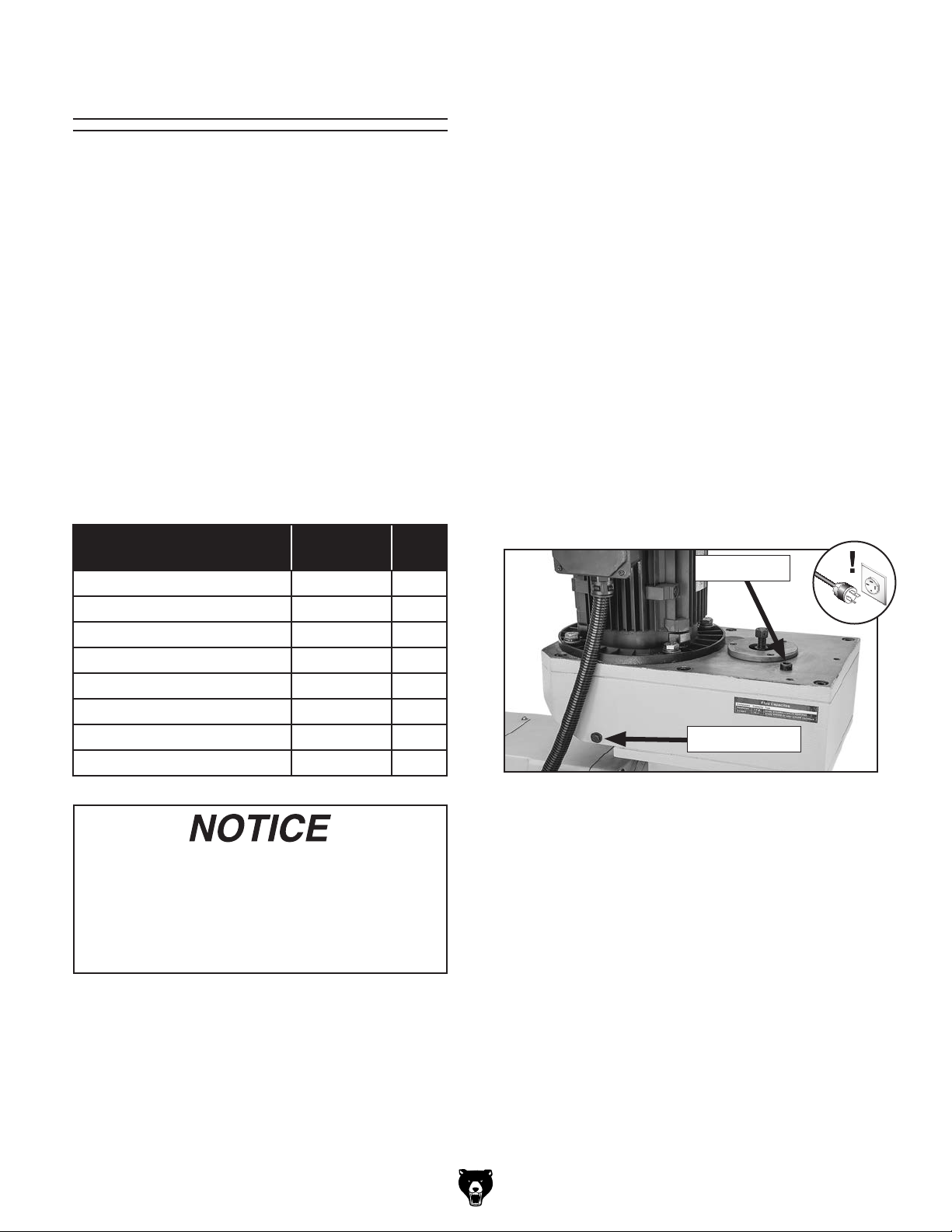
Lubrication
The mill has numerous moving metal-to-metal
contacts that require regular and proper lubrication to ensure efficient and long-lasting operation.
Use the schedule and information in the chart
below as a daily guide for lubrication tasks.
Headstock
Oil Type ......Model T23963 or ISO 32 Equivalent
Oil Amount
Lubrication Frequency
The headstock uses ISO 32 machine oil to lubricate the gears, and is equipped with an oil-level
sight glass to gauge when the proper amount of
oil is in the headstock.
.......................................... 1.9 Quarts
........................... Annually
Other than the lubrication points covered in this
section, all other bearings are internally lubricated
and sealed at the factory. Simply leave them
alone unless they need to be replaced.
DISCONNECT MACHINE FROM POWER before
performing any lubrication task!
Important: Before adding lubricant, clean all
debris and grime from part and nearby area to
prevent contamination of new lubricant.
Lubrication Task
Ball Oilers 4–8
Vertical Spindle Bearings 4–8
Quill Exterior 4–8
Quill Rack & Pinion 40
Table Leadscrews 40
Ram Ways 40
Z-Axis Bevel Gears 80
Power Feed Gears 80
(Hours of
Operation)
Page
Ref.
47
48
48
49
49
49
49
50
The amount of oil in the headstock must be
regularly monitored before each operation to
ensure it doesn't drop below sight glass visibility.
Headstock oil must be changed on an annual
basis to ensure proper lubricity of oil.
To change oil in headstock:
1.
DISCONNECT MACHINE FROM POWER!
2. Remove oil fill plug from top of headstock
(see Figure 72).
Oil Fill Plug
Oil Drain Plug
Figure 72. Headstock oil fill and drain locations.
The recommended lubrication schedule is
based on light-to-medium usage. Keeping
in mind that lubrication helps to protect
the value and operation of the mill, these
lubrication tasks may need to be performed
more frequently depending on usage.
Tools Needed Qty
Open-End Wrenches 12, 17, 19mm .............1 Ea.
Hex Wrench 8mm
Drain Pan (1 Gallon or Larger)
Pump-Type Oil Can with Plastic or Rubber Tip
Mineral Spirits
Shop Rags
Brush
Model G0827 (Mfd. Since 11/17)
......................................... As Needed
................................................................. 1
.............................................. 1
.......................... 1
. 1
.................................... As Needed
3. Hold drain pan under drain plug and remove
drain plug. Allow old oil to drain into drain
pan.
. Replace and tighten drain plug.
4
-45-
Page 48

5. Fill headstock with oil to red mark on sight
glass (see Figure 73).
Oil-Level
Sight Glass
Red Mark
Figure 73. Red mark on sight glass indicates
headstock oil level is full.
Do not fill headstock with oil above red
mark. This could damage machine and
create an overflow of oil.
Column
Oil Type ......Model T23963 or ISO 32 Equivalent
Oil Amount
Lubrication Frequency
The column uses ISO 32 machine oil to lubricate
the gears, and is equipped with an oil-level sight
glass to gauge when the proper amount of oil is
in the column.
The amount of oil in the column must be regularly monitored before each operation to ensure it
doesn't drop below sight glass visibility. Column
oil must be changed on an annual basis to ensure
proper lubricity of oil.
To change oil in column:
DISCONNECT MACHINE FROM POWER!
1.
2. Loosen hex bolt shown in Figure 74 and
open rear column cover.
.......................................... 2.6 Quarts
........................... Annually
6. Re-install oil fill plug.
7. Discard used oil following federal, state,
and fluid manufacturer guidelines for proper
disposal.
Remove oil fill plug (see Figure 74).
3.
Oil Fill
Plug
Oil Drain
Plug
Figure 74. Column oil fill and drain locations.
. Hold drain pan under drain plug and remove
4
drain plug. Allow old oil to drain into drain
pan.
. Replace and tighten drain plug shown in
5
Figure 74.
-46-
Model G0827 (Mfd. Since 11/17)
Page 49
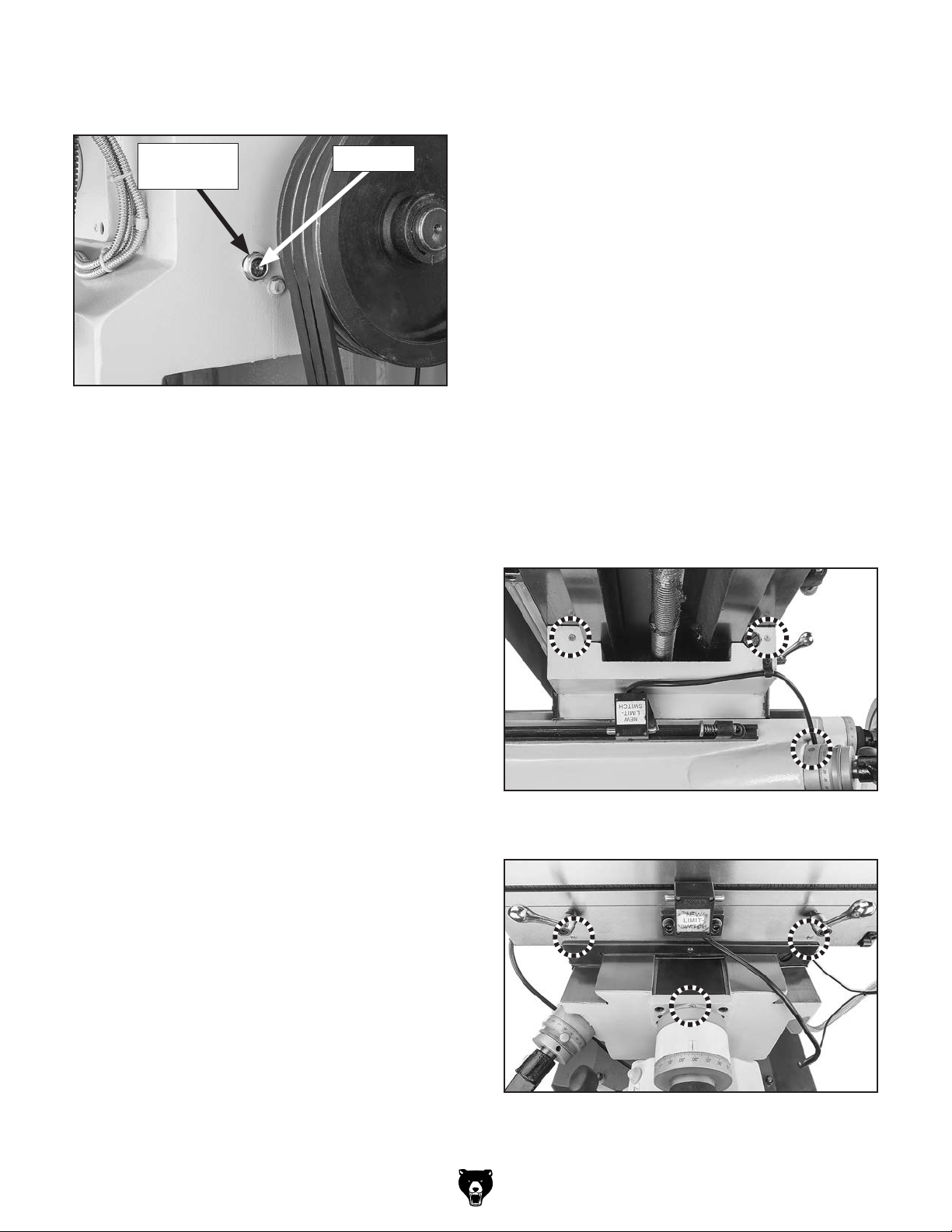
6. Fill column with oil to red mark on sight glass
(see Figure 75).
Oil-Level
Sight Glass
Figure 75. Red mark on sight glass indicates
column oil level is full.
7
. Re-install oil fill plug.
Red Mark
Ball Oilers
Oil Type ......Model T23963 or ISO 32 Equivalent
Oil Amount
Lubrication Frequency
Proper lubrication of ball oilers is done with
a pump-type oil can that has a cone tip (see
Page 40 for offerings from Grizzly). We do not
recommend using metal needle or lance tips, as
they can push the ball too far into the oiler, break
the spring seat, and lodge the ball in the oil galley.
Push the tip of the oil can nozzle against the ball
oiler to create a hydraulic seal, then pump the oil
can once or twice. If you see sludge and contaminants coming out of the lubrication area, continue
pumping the oil can until the oil runs clear. Move
the components through the entire path of travel a
few times to distribute the oil. When finished, wipe
away the excess oil.
.........................................1–2 Pumps
...... 4–8 Hrs. of Operation
8. Close and secure rear column cover.
9. Discard used oil following federal, state,
and fluid manufacturer guidelines for proper
disposal.
Use Figures 76–82 to locate the 11 ball oilers on
the Model G0827.
Figure 76. Ball oilers on the side of the knee
and Z-axis crank ball oiler.
Model G0827 (Mfd. Since 11/17)
Figure 77. Front saddle and Y-axis handwheel
ball oilers.
-47-
Page 50

Figure 78. Spindle ball oiler.
Figure 79. (Left) turret ball oiler.
Figure 82. Left longitudinal handwheel ball oiler.
Vertical Spindle Bearings
Oil Type ......Model T23963 or ISO 32 Equivalent
Oil Amount
Lubrication Frequency
To lubricate vertical spindle bearings:
DISCONNECT MACHINE FROM POWER!
1.
2. Remove circular cover on right side of
headstock to expose vertical spindle spline
(see Figure 83).
.........................................1–2 Pumps
...... 4–8 Hrs. of Operation
Spindle
Spline
Exposed
Figure 80. (Right) turret ball oiler.
Figure 81. Horizontal spindle arbor support ball
oiler.
-48-
Figure 83. Vertical spindle spline exposed for
lubrication.
3.
Raise spindle until you can see top of quill.
4. Add 1–2 pumps from an oil can between
spindle spline and top of quill.
Replace circular cover and run vertical spin-
5.
dle for a few minutes to distribute oil in
bearings.
Model G0827 (Mfd. Since 11/17)
Page 51

Quill Exterior
Oil Type ......Model T23962 or ISO 68 Equivalent
Oil Amount
Lubrication Frequency
............................................Thin Coat
...... 4–8 Hrs. of Operation
Table Leadscrews
Oil Type ......Model T23962 or ISO 68 Equivalent
Oil Amount
Lubrication Frequency
............................................Thin Coat
.........40 Hrs. of Operation
Fully extend the spindle to expose the quill
(see Figure 84), then use an oily shop rag to
apply a thin coat of lubricant to the smooth surface of the quill.
Note: If you remove any of the grease from the
teeth of the quill rack, replace it as instructed
below.
Pinion
Rack
Quill
Smooth
Surface
Figure 84. Quill lubrication points.
Move the table as necessary to access the entire
length of the X-, Y-, and Z-axis leadscrews (see
Figures 85–86), then use mineral spirits, shop
rags, and a brush to clean them.
X-Axis
Leadscrew
Figure 85. X-axis leadscrew
(as viewed underneath the table).
Y-Axis
Leadscrew
Quill Rack & Pinion
Grea s e Typ e ......... NLGI#2 Grease or Equivalent
Oil Amount
Lubrication Frequency
Fully extend the spindle to expose the quill rack
(see Figure 84), then use mineral spirits, shop
rags, and a brush to clean the old grease from the
teeth of the rack and pinion.
When dry, use a brush to apply a thin coat of
grease to the teeth, then move the quill up and
down several times to evenly distribute the grease.
............................................Thin Coat
.........40 Hrs. of Operation
Z-Axis
Leadscrew
Figure 86. Y- and Z-axis leadscrews
(as viewed underneath the knee).
When dry, use a clean brush to apply a thin coat
of oil to the leadscrew threads, then move the
table through the X-, Y-, and Z-axis paths to distribute the oil.
Model G0827 (Mfd. Since 11/17)
-49-
Page 52

Ram Ways
Oil Type ......Model T23962 or ISO 68 Equivalent
Oil Amount
Lubrication Frequency
............................................Thin Coat
.........40 Hrs. of Operation
X- & Y-Axis Power Feed Gears
Grea s e Typ e .........T23964 or NLGI#2 Equivalent
Amount
Add Frequency
.................................................Thin Coat
....................40 Hrs. of Operation
Move the ram as necessary to gain access
to the entire length of the ram dovetail ways
(see Figure 87), use mineral spirits and shop
rags to clean the ways, then apply a thin coat of
lubricant.
Ram Dovetail Ways
Figure 87. Ram dovetail ways.
Z-Axis Bevel Gears
Grea s e Typ e ......... NLGI#2 Grease or Equivalent
Oil Amount
Lubrication Frequency
Use mineral spirits, shop rags, and a brush to
clean the old grease from the teeth of the bevel
gears shown in Figure 88.
............................................Thin Coat
.........80 Hrs. of Operation
To lubricate power feed gears:
DISCONNECT MACHINE FROM POWER!
1.
2. Remove acorn nut and handwheel from
power unit end of the X-axis leadscrew
(see Figure 89).
Unthread and remove knurled retaining ring
3.
and graduated dial ring from end of leadscrew
(see Figure 89).
Graduated
Dial
Figure 89. X-Axis handwheel components to
remove to lubricate power feed gears.
Knurled
Retaining Ring
Handwheel
Acorn Nut
Figure 88. Location of Z-axis bevel gears.
When dry, use a clean brush to apply a thin coat
of grease to the teeth, then move the table up and
down to evenly distribute the grease.
-50-
Model G0827 (Mfd. Since 11/17)
Page 53

4.
Remove brass bevel gear from leadscrew,
then remove leadscrew alignment key
(see Figure 90).
Key
Brass
Bevel Gear
Figure 90. Power feed gears and key.
5. Brush a light coat of grease on bevel gear
teeth and smaller drive gear.
Drive
Gear
Adding/Changing
Coolant
Hazards
As some coolant ages, dangerous microbes can
proliferate and create a biological hazard. The risk
of exposure to this hazard can be greatly reduced
by replacing the old coolant on a regular basis, as
indicated in the maintenance schedule.
The important thing to keep in mind when working
with the coolant is to minimize exposure to your
skin, eyes, and respiratory system by wearing
the proper PPE (personal protective equipment),
such as splash-resistant safety glasses, longsleeve gloves, protective clothing, and a NIOSHapproved respirator.
Replace leadscrew alignment key, then align
6.
bevel gear keyway with key as you slide gear
onto leadscrew and mesh its teeth with drive
gear.
Replace graduated dial ring and secure it with
7.
knurled retaining ring—do not overtighten.
Slide handwheel onto leadscrew, align key-
8.
way with leadscrew alignment key, then
secure it with acorn nut removed in Step 2.
Move table with handwheel to check gear
9.
movement and distribute grease on gears. If
movement is not smooth, repeat Steps 2–8
until it is.
Repeat Steps 1–9 for Y-axis power feed.
10.
BIOLOGICAL & POISON
HAZARD!
Use the correct personal protection equipment
when handling coolant.
Follow federal, state,
and fluid manufacturer
requirements for proper
disposal.
A small amount of coolant is lost during normal
operation. Check the coolant reservoir regularly
and fill it if necessary. We recommend changing the coolant every three months or sooner if it
develops an unpleasant odor. However, be sure
to follow the coolant manufacturer's instructions
when checking, adding, or changing coolant.
Coolant Reservoir Capacity ..... 4.75 Gal. (18L)
Model G0827 (Mfd. Since 11/17)
Running coolant pump without adequate
coolant in reservoir may permanently
damage coolant pump, which will not be
covered by warranty.
-51-
Page 54

Checking/Adding Coolant
Items Needed Qty
Hex Wrench 3mm .............................................. 1
Goggles
Gloves
Respirator
New Coolant
Disposable Shop Rags
To check or add coolant:
1. DISCONNECT MACHINE FROM POWER!
Clean away debris and grime from coolant
2.
.......................................... 1 Per Person
............................................ 1 Per Person
....................................... 1 Per Person
...... Approx. 4.75 Gallons (18 Liters)
...................... As Needed
return screen and surrounding area, then
remove screen from base, as shown in
Figure 91.
Coolant
Return Screen
Changing Coolant
Items Needed Qty
Hex Wrench 3mm .............................................. 1
Catch Pan
Empty Bucket 5-Gal.
Rubber Hose (optional)
Goggles
Gloves
Respirator
New Coolant
Disposable Shop Rags
To change coolant:
Put on personal protective equipment.
1.
2. Place catch pan on table, position coolant
Note: When catch pan is near full, empty it
.......................................................... 1
......................................... 1
..................................... 1
.......................................... 1 Per Person
............................................ 1 Per Person
....................................... 1 Per Person
...... Approx. 4.75 Gallons (18 Liters)
...................... As Needed
nozzle into pan, then use coolant pump to
drain reservoir.
into a 5-gallon bucket, then repeat process
until reservoir is empty.
Figure 91. Coolant return screen removed.
Use a clean metal tool as a dip stick to mea-
3.
sure the level of coolant in reservoir. If lower
than 1 1⁄2" (measured from bottom of tank),
add coolant by pouring it into return screen
hole.
Re-install return screen before resuming mill-
4.
ing operations.
Tip: As an alternate method, leave return
screen in place. For a dip stick, use a clean,
metal tool that is narrow enough to fit through
screen hole and long enough to measure
coolant depth.
Tip: Alternately, slide rubber hose onto cool-
ant nozzle and point it into 5-gallon bucket.
DISCONNECT MACHINE FROM POWER!
3.
4. Clean away debris from coolant return screen
and surrounding area, then remove screen
from base.
Thoroughly clean out reservoir. Make sure
5.
interior is dry before adding new coolant.
Note: Use a shop vacuum and a cleaning
solution that is compatible with type of coolant. For instance, if you are using a waterbase coolant, then use a water-base cleaning
solvent. Also, use magnets to remove any
metal chips left behind.
When reservoir is clean and dry, fill reservoir
6.
with new coolant through hole under return
screen.
Tip: Place a couple of magnets inside res-
ervoir under return screen to collect metal
particles and keep them out of coolant pump.
-52-
Re-install return screen before resuming mill-
7.
ing operations.
Model G0827 (Mfd. Since 11/17)
Page 55

Tensioning/
Replacing V-Belts
To ensure optimum power transmission from the
horizontal spindle motor to the arbor, the V-belts
must be in good condition (free from cracks, fraying, and wear) and properly tensioned. After the
first 16 hours of belt life, re-tension the V-belts, as
they will stretch and seat during this time.
All V-belts can be replaced by releasing the tension and rolling them off the pulleys, then rolling the new belts back onto the pulleys. Always
replace V-belts with a matched set of three belts,
or belt tension may not be even among the three
belts and may cause premature belt failure.
Tools Needed Qty
Open-End Wrench 17mm .................................. 1
Open-End Wrench 19mm
.................................. 1
4. Press down on motor until approximately
1
⁄4" –1⁄2" deflection is achieved (see Figure 93)
by applying moderate pressure midway
between pulleys.
1
⁄4"–1⁄2"
Deflection
Figure 93. Checking V-belt tension.
5.
Tighten top hex nut to hold motor in place,
then tighten bottom hex nut to secure belt
tension.
Close and secure rear column cover.
6.
Pulley
Pulley
Tensioning V-Belts
1.
DISCONNECT MACHINE FROM POWER!
2. Open rear column cover to gain access to
horizontal spindle V-belts and pulleys.
Loosen top hex nut (see Figure 92) on retain-
3.
ing bolt, then adjust bottom hex nut down.
V-Belts
Retaining
Bolt
Hex
Nuts
Motor Bracket
Figure 92. Location of hex nuts for adjusting
V-belt tension.
Replacing V-Belts
1. DISCONNECT MACHINE FROM POWER!
Open rear column cover to gain access to
2.
horizontal spindle V-belts and pulleys.
Loosen top hex nut shown in Figure 92
3.
enough to swing retaining bolt away from
motor bracket.
While lifting motor, remove and replace
4.
V-belts.
Re-install retaining bolt onto motor bracket,
5.
making sure hex nuts and flat washers are in
same position above and below bracket as
they were originally.
Follow Steps 4–5 in Tensioning V-Belts
6.
procedure to set correct belt tension.
Close and secure rear column cover.
7.
Model G0827 (Mfd. Since 11/17)
-53-
Page 56

Machine Storage
Bringing Mill Out of Storage
1. Re-tension V-belts (refer to Page 53) if you
loosened them for storage purposes.
The machine must be properly prepared if it will
be stored for any period of time. Doing this will
help prevent the development of rust and corrosion and ensure the mill remains in good condition
for later use.
Note: When taking the machine out of storage,
repeat the Test Run and the Spindle Break-In.
Preparing Mill for Storage
1. DISCONNECT MACHINE FROM POWER!
2. Lubricate machine as directed in Lubrication
on Page 45.
Clean out coolant reservoir as directed in
3.
Changing Coolant on Page 51.
Thoroughly clean all unpainted, bare metal
4.
surfaces, then coat them with quality rust preventative. Take care to ensure these surfaces
are completely covered but rust preventative
is kept off painted surfaces.
Remove moisture-absorbing desiccant packs
2.
from the electrical box.
Repeat Test Run and Spindle Break-In pro-
3.
cedures, beginning on Page 24.
Add coolant, as described in Adding/
4.
Changing Coolant on Page 51.
Note: If the machine will be out of service
for only a short period of time, use way oil in
place of rust preventative.
Loosen belts to prevent them from stretching
5.
during storage. Post a reminder on machine
that belts need to be re-installed or tensioned
before resuming operations.
Place a few moisture-absorbing desiccant
6.
packs inside electrical cabinet.
Cover and place machine in a dry area that
7.
is out of direct sunlight and away from hazardous fumes, paint, solvents, or gas. Fumes
and sunlight can bleach or discolor paint and
plastic parts.
-54-
Model G0827 (Mfd. Since 11/17)
Page 57

Review the troubleshooting procedures in this section if a problem develops with your machine. If you need
the
serial number and manufacture date of your machine before calling.
SECTION 7: SERVICE
replacement parts or additional help with a procedure, call our Technical Support. Note: Please gather
Troubleshooting
Motor & Electrical
Symptom Possible Cause Possible Solution
Machine does not
start or a breaker
trips immediately
upon startup.
Machine stalls or is
underpowered.
1. Master power switch OFF or at fault.
2. E-Stop Button depressed/at fault.
3. POWER lamp button not engaged.
4. Plug/receptacle at fault/wired incorrectly.
5. Incorrect power supply voltage or circuit
size.
6. Column cover limit switch disengaged or at
fault.
7. Power supply circuit breaker tripped or fuse
blown.
8. Thermal overload relay has tripped.
9. Motor wires connected incorrectly.
10. Contactor not energized/has poor contacts.
11. Spindle rotation switch at fault.
12. Motor at fault.
1. Machine undersized for task.
2. Feed rate/cutting speed too fast.
3. Improper tooling or wrong workpiece
material.
4. Belt(s) slipping. Oil/grease on belt(s).
5. Motor wired incorrectly.
6. Motor overheated.
7. Pulley slipping on shaft.
8. Gearbox at fault.
9. Motor bearings at fault.
1. Turn master power switch ON or replace if at fault.
2. Rotate E-Stop Button head to reset. Replace.
3. Press POWER lamp button.
4. Test for good contacts; correct wiring.
5. Ensure correct power supply voltage and circuit
size.
6. Close cover to engage switch; replace if at fault.
7. Ensure circuit is sized correctly and free of shorts.
Reset circuit breaker or replace fuse.
8. Reset; adjust trip load dial if necessary; replace.
9. Correct motor wiring connections.
10. Test all legs for power; replace if necessary.
11. Test/replace switch.
12. Test/repair/replace.
1. Use correct cutter/bit; reduce feed rate; reduce
spindle RPM; use coolant if possible.
2. Decrease feed rate/cutting speed.
3. Use proper cutting tools and workpiece materials.
4. Tension/replace belt(s) (Page 53); clean belt(s) of
any oil/grease.
5. Wire motor correctly (Page 69).
6. Clean motor, let cool, and reduce workload.
7. Replace loose pulley.
8. Select appropriate gear ratio; replace broken or
slipping gears.
9. Test by rotating shaft; rotational grinding/loose shaft
requires bearing replacement.
Model G0827 (Mfd. Since 11/17)
-55-
Page 58

Symptom Possible Cause Possible Solution
Machine has
vibration or noisy
operation.
1. Workpiece loose.
2. Cutter at fault.
3. V-belt(s) worn, loose, or misaligned.
4. Motor or component loose.
5. Motor fan rubbing on fan cover.
8. Pulley loose.
7 Arbor bearings at fault.
8. Motor bearings at fault.
9. Gearbox at fault.
1. Use correct holding fixture and reclamp workpiece.
2. Replace/resharpen cutter; use correct feed rate.
3. Inspect/replace belts with new matched set
(Page 53). Realign pulleys if necessary.
4. Inspect/replace damaged bolts/nuts, and retighten
with thread locking fluid.
5. Fix/replace fan cover; replace loose/damaged fan.
6. Re-align/replace pulley/shaft, pulley set screw, and
key.
7. Replace arbor housing bearings; replace arbor.
8. Test by rotating shaft; rotational grinding/loose shaft
requires bearing replacement.
9. Rebuild gearbox for bad gear(s)/bearing(s).
Mill Operations
Symptom Possible Cause Possible Solution
Tool loose in
spindle.
Breaking tools or
cutters.
Workpiece or tool
vibrates or chatters
during operation.
Table hard to move.
Table hard to raise.
Spindle overheats.
1. Tool not fully drawn up into spindle taper.
2. Debris on tool or in spindle taper.
3. Taking too big of a cut.
1. Spindle speed/feed rate too fast for
material type or cutting depth.
2. Cutting tool too small.
3. Spindle extended too far down.
4. Cutting tool getting too hot.
1. Table locks not tight.
2. Workpiece loose/improperly secured.
3. Spindle speed/feed rate too fast for
material type or cutting depth.
4. Spindle extended too far down.
5. Quill lock not tight.
6. Gibs too loose in table.
1. Table locks tightened.
2. Chips loaded up on table ways.
3. Ways dry and need lubrication.
4. Table limit stops interfering.
5. Gibs too tight.
6. X/Y-Axis leadscrews binding.
1. Table lock(s) tightened.
2. Gibs too tight.
3. Z-axis leadscrew binding.
1. Poor spindle bearing lubrication.
2. Mill operated at high speeds for extended
period.
3. Spindle bearings too tight.
1. Tighten drawbar (Page 33).
2. Clean tool and spindle taper.
3. Lessen depth of cut and allow chips to clear.
1. Reduce spindle speed (Page 36) or use slower feed
rate, or a shallower depth of cut, or both.
2. Use larger cutting tool.
3. Fully retract spindle (Page 38) and raise table
(Page 30). This increases rigidity.
4. Use coolant or oil for appropriate application.
1. Tighten table locks (Page 30).
2. Use correct holding fixture and reclamp workpiece.
3. Reduce spindle speed (Page 36) or use slower feed
rate, or a shallower depth of cut, or both.
4. Fully retract spindle (Page 38) and raise table
(Page 30). This increases rigidity.
5. Tighten quill lock (Page 38).
6. Tighten gibs (Page 61).
1. Fully release table locks (Page 30).
2. Frequently clean chips or debris away from ways.
3. Lubricate ways.
4. Move table limit stops out of the way.
5. Adjust gibs (Page 61).
6. Clean and lubricate leadscrews; adjust leadscrew
backlash or decrease bearing preload.
1. Loosen table locks (Page 61).
2. Adjust gibs (Page 61).
3. Clean and relubricate Z-axis leadscrew and bevel
gears (Page 50). Decrease leadscrew bearing
preload.
1. Lubricate spindle bearings.
2. Allow mill to cool.
3. Properly adjust spindle bearing preload.
-56-
Model G0827 (Mfd. Since 11/17)
Page 59

Symptom Possible Cause Possible Solution
Bad surface finish. 1. Spindle speed/feed rate too fast for
material type.
2. Depth of cut too deep.
3. Cutting tool is dull or incorrect for
application.
4. Cutting tool rotation is backwards.
5. Workpiece not properly secured.
6. Spindle extended too far down.
7. Non-traveling table axis not locked.
Cutting results not
square.
Lack of power at
spindle.
Spindle does not
fully retract.
Control Panel
FORWARD and
REVERSE buttons
do not work.
1. Table and spindle not at 90° to each other.
2. Table travel inconsistent.
1. Belt(s) slipping. Oil/grease on belt(s).
2. Incorrect power supply voltage or
frequency.
1. Worn return spring. 1. Replace return spring.
1. Shorted/disconnected wiring.
2. Button switch at fault.
1. Set spindle speed correctly for material type (Page
36) or use a slower feed rate.
2. Reduce depth of cut.
3. Sharpen cutting tool; select a better cutting tool for
operation.
4. Check for proper cutting tool rotation direction.
5. Properly clamp workpiece to table or in a vise.
6. Fully retract spindle (Page 38) and raise table
(Page 30). This increases rigidity.
7. Use Z-axis or other table locks to prevent slight
table movement where axis must be fixed.
1. Tram spindle (Page 58).
2. Adjust gibs (Page 61).
1. Tension/replace belt(s) (Page 53); clean belt(s) of
any oil/grease.
2. Ensure power supply meets correct circuit
requirements (Page 14).
1. Inspect circuit boards, wiring connections. Replace/
repair as necessary.
Power Feed
Symptom Possible Cause Possible Solution
Power feed does
not move table or is
slipping.
Operates at high
speed only or is
inconsistent.
1. Table locked.
2. Drive selector not engaged.
3. Sheared pin.
4. Gears not meshing or teeth missing.
5. Motor shaft and gear shaft not engaged.
1. Rapid micro switch stuck.
2. Wiring harness disconnected.
3. Variable-speed dial (potentiometer) at fault.
1. Unlock table locks (Page 30).
2. Select speed and engage drive selector.
3. Replace pin.
4. Check gears and adjust/replace.
5. Replace clutch.
1. Lightly tap on it to lower it; replace.
2. Reconnect wiring harness.
3. Replace potentiometer.
Lamp
Symptom Possible Cause Possible Solution
Lamp will not light. 1. Main power not turned ON.
2. Bulb burned out.
3. Short in wiring or wired incorrectly.
1. Press switch/button on lamp or control panel.
2. Replace bulb.
3. Trace/test wiring to ensure proper connections and
verify continuity. Replace or fix as necessary.
Digital Readout Unit (DRO)
Symptom Possible Cause Possible Solution
DRO doesn't give
reading.
DRO reading is
incorrect.
1. DRO not turned ON.
2. DRO not getting power.
1. Initial reading incorrect.
2. Sensor at fault.
1. Switch DRO ON/Power button.
2. Inspect circuit boards, sensors, plugs, and wiring
connections. Replace/repair as necessary.
1. Zero/Reset DRO at beginning point.
2. Test/replace sensor as necessary.
Model G0827 (Mfd. Since 11/17)
-57-
Page 60
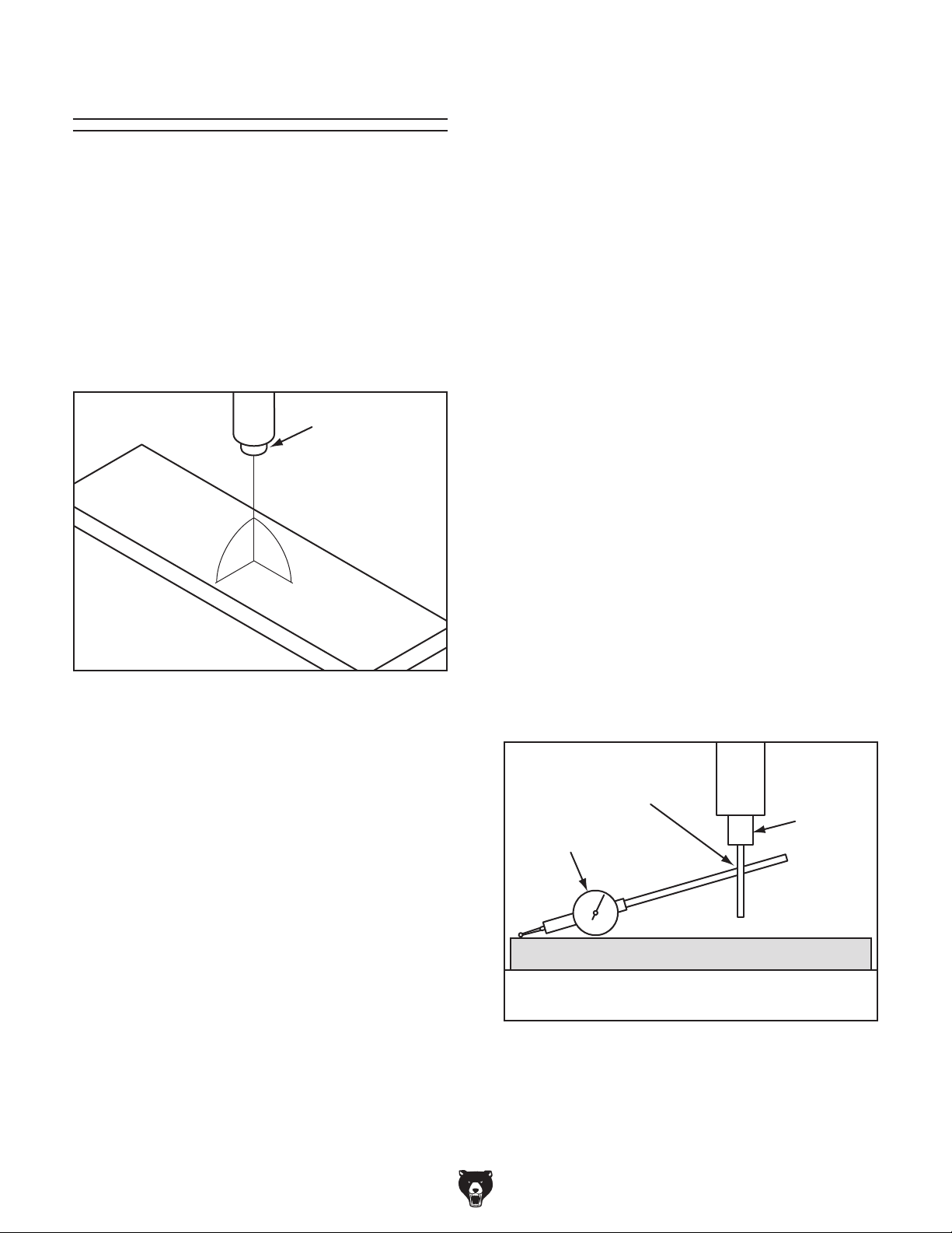
Tramming Mill Head
After positioning the head at an angle and when
your operation requires that the spindle axis be
precisely perpendicular to the table, you must
tram or align the spindle with the table to ensure
the spindle is exactly 90° to the table.
Note: A precision-ground plate can be substituted for the parallel blocks. Keep in mind that
the farther the indicator point can be placed from
the spindle axis, the more accurate the alignment
measurements will be.
To tram spindle to mill head:
DISCONNECT MACHINE FROM POWER!
1.
This procedure involves mounting a dial test
indicator to the quill or spindle, rotating it around
the table, and adjusting the spindle axis (Z-axis)
90° to the table X- and Y-axes, as illustrated in
Figure 94.
Spindle
Z-Axis
Y-Axis
Figure 94. Spindle Z-axis perpendicular to the
table X- and Y-axis.
90º
90º
X-Axis
Table
2. Prepare the mill for tramming by performing
following tasks:
• Verify the table is clean by running your
hand over the top of it. If necessary, stone
the table to remove all nicks and burrs,
then clean off all debris.
• Position the table for the milling operation
you intend to perform after tramming—
preferably centered with the saddle.
• Tighten any table, knee, quill, or ram locks
that should be tight during the intended
milling operation.
Place parallel block underneath spindle.
3.
4. Install indicator holder in spindle or on quill,
then mount indicator so that point is as parallel to the block as possible (see illustration in
Figure 95).
We encourage you to research the many variations of spindle tramming to find the one that
works best for you. If you do not already have a
preference for performing this operation, use the
following widely used procedure for accurately
tramming the spindle to the table.
Keep in mind that all workpiece top surfaces are
not exactly parallel with the table top. You may
choose to tram the spindle to the top surface of
the workpiece after it is mounted instead of that
of the table.
Tools Needed Qty
Dial Test Indicator
(with at least 0.0005" resolution) ................ 1
Indicator Holder
(mounted on the quill/spindle) .................... 1
Precision Parallel Block
(at least 9" in length) ................................... 1
-58-
Indicator Holder
Dial Test
Indicator
Parallel Block
Table
Figure 95. Dial test indicator mounted.
Model G0827 (Mfd. Since 11/17)
Spindle
Page 61
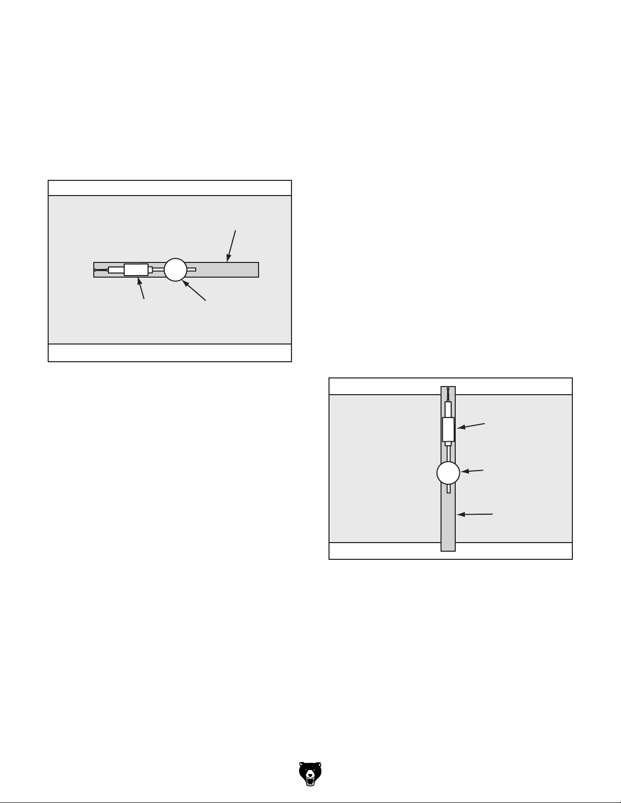
5. To measure spindle alignment along X-axis,
place parallel block directly under spindle and
indicator across length of table, as illustrated
in Figure 96.
Note: If you must position quill or knee to
accommodate above step, then review the
tasks in Step 2 to make sure the mill is properly prepared for tramming.
Table (Top View)
Parallel Block
Indicator
Figure 96. Parallel block and indicator positioned
for the X-axis measurement (top view).
Spindle
Rotate spindle so that indicator point rests
7.
in same manner on other end of block, then
read dial.
— If indicator dial still reads zero or is within
the acceptable variance, continue on with
Step 8.
— If indicator dial has moved from zero
beyond acceptable variance, you will need
to compensate for that amount by rotating head left or right. Repeat Steps 6–7
until you are satisfied with the spindle axis
alignment along table X-axis.
Note: Keep one of the rotation lock bolts
just snug so the head does not move loosely
while you adjust it. Remember to tighten
all the rotation lock bolts after adjusting the
head.
Place parallel block directly under spindle
8.
and across width of table, as illustrated in
Figure 97.
Note: Your general goal in the next steps
should be to get the difference of the indicator
readings between the ends of the parallel bar
down to 0.0005". However, the acceptable
variance will depend on the requirements for
your operation.
Rotate spindle by hand so that indicator point
6.
rests on one end of parallel block, as illustrated in Figures 95–96, then zero dial.
Table (Top View)
Indicator
Spindle
Parallel Block
Figure 97. Parallel block and indicator positioned
for the Y-axis measurement (top view).
Model G0827 (Mfd. Since 11/17)
-59-
Page 62

9. Rotate spindle so indicator point rests on parallel block, as illustrated in Figure 97, then
zero dial.
Rotate spindle so that indicator point rests on
10.
other end of block in same manner, then read
dial.
— If indicator dial still reads zero or is within
the acceptable variance, the spindle is
precisely perpendicular to table in both
X- and Y-axes, and tramming procedure
is complete.
— If indicator dial has moved from zero
beyond acceptable variance, you will need
to compensate for that amount by tilting
head forward or backward. Repeat Steps
9–10 until you are satisfied with spindle
axis alignment along table Y-axis.
Adjusting Leadscrew
Backlash
Leadscrew backlash is the amount of free play
movement in the leadscrew (when the leadscrew
moves but the table does not) after changing the
direction of rotation.
A leadscrew must have a certain amount of backlash to rotate easily, but over time, it increases
with wear. Generally, 0.005"–0.010" leadscrew
backlash is acceptable to ensure smooth movement and reduce premature thread wear.
Tool Needed Qty
Flat Head Screwdriver ....................................... 1
Adjustable Spanner Wrench
.............................. 1
Note: Keep one of the tilt lock bolts just snug
so the head does not move loosely while you
adjust it. Remember to tighten all the tilt lock
bolts after adjusting the head.
Adjusting X-Axis Leadscrew
Backlash
DISCONNECT MACHINE FROM POWER!
1.
Locate X-axis leadscrew backlash adjusting
2.
screws underneath right side of table (see
Figure 98).
Top Adjusting Screw
Bottom Adjusting Screw
Figure 98. X-axis leadscrew backlash adjusting
screws.
Note: The bottom screw adjusts the amount
of backlash, and the top screw, when tightened, locks the bottom screw setting.
-60-
Loosen top screw, and tighten bottom screw
3.
until slightly snug.
Re-tighten top screw to lock bottom screw
4.
setting.
Check amount of backlash by rotating X-axis
5.
handwheel.
Model G0827 (Mfd. Since 11/17)
Page 63
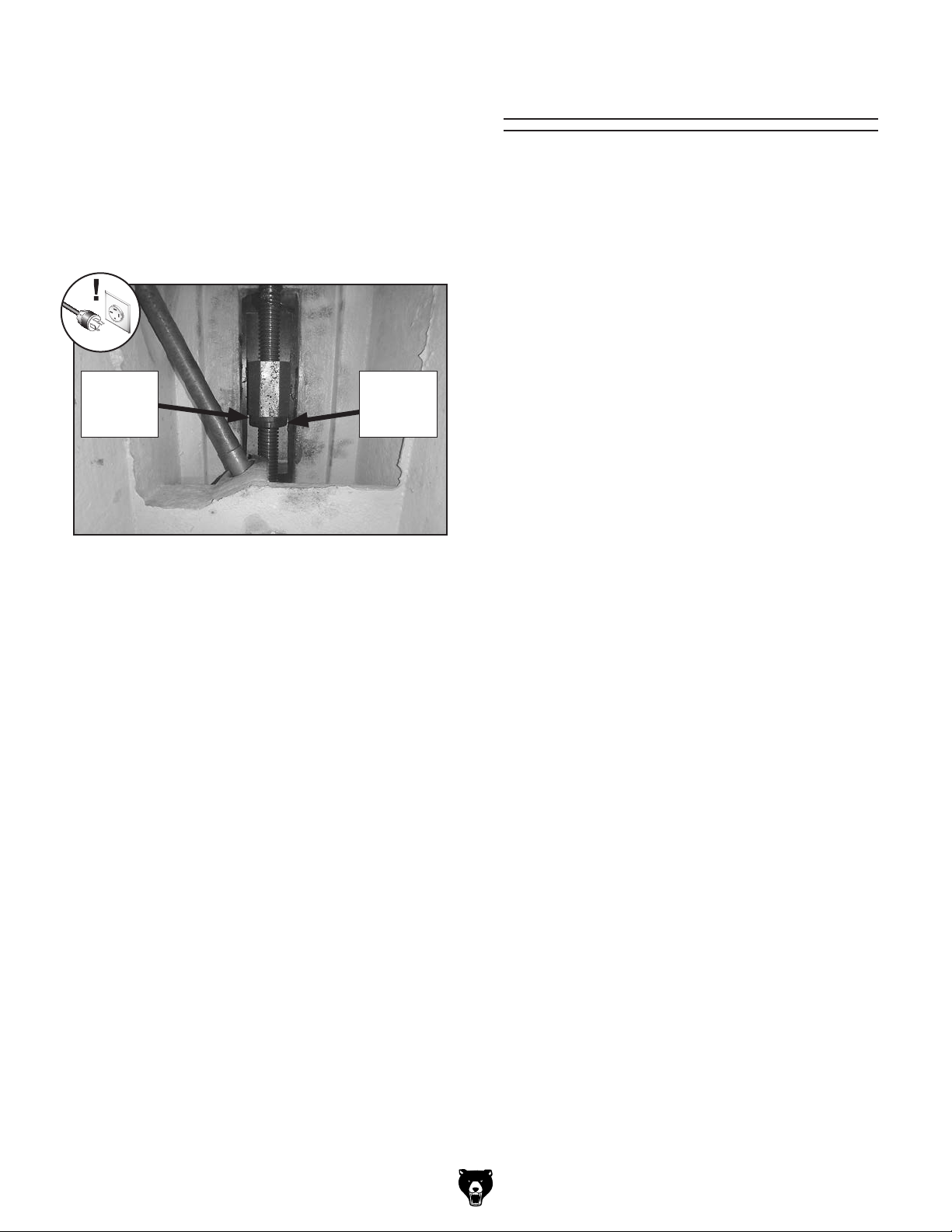
Repeat Steps 3–5 if necessary.
6.
Adjusting Y-Axis Leadscrew
Backlash
1.
DISCONNECT MACHINE FROM POWER!
Locate Y-axis leadscrew backlash adjust-
2.
ing spanner nuts underneath knee (see
Figure 99).
Front
Spanner
Nut
Figure 99. Y-axis leadscrew backlash adjusting
spanner nuts (viewed underneath knee).
Note: The front spanner nut adjusts the
amount of backlash, and the rear spanner nut
when tightened, locks the front spanner nut
setting.
Loosen rear spanner nut and tighten front
3.
spanner nut until slightly snug.
Re-tighten rear spanner nut to lock front
4.
spanner nut setting.
Rear
Spanner
Nut
Adjusting Gibs
Gibs are tapered lengths of metal that are sandwiched between two moving surfaces. Gibs control the gap between these surfaces and how they
slide past one another. Correctly adjusting the
gibs is critical to producing good results.
Correctly positioning gibs is a matter of trial and
error and patience. Tight gibs make table movement more accurate but stiff. Loose gibs make
table movement sloppy but easier to do. The goal
of gib adjustment is to remove unnecessary sloppiness without causing the ways to bind.
Many experienced machinists adjust the gibs just
to the point where they can feel a slight drag in
table movement.
Screws on each end of the X- and Y-axis gibs
allow gib adjustment to increase or decrease the
friction between the sliding surfaces. The exception to this arrangement is the column dovetail
way (Z-axis) gibs.
DISCONNECT MACHINE FROM POWER
BEFORE ADJUSTING GIBS!
Tools Needed Qty
Flat Head Screwdriver ....................................... 1
Hex Wrench 6mm
Hex Wrench 10mm
Open-End Wrench 19mm
.............................................. 1
............................................ 1
.................................. 1
Check amount of backlash by rotating Y-axis
5.
handwheel.
Repeat Steps 3–5 if necessary.
6.
Model G0827 (Mfd. Since 11/17)
-61-
Page 64

Adjusting X- & Y-Axis Gibs
1. Make sure all table locks are loose.
2. Loosen one gib adjustment screw
(see Figure 100) and tighten opposite screw
same amount to move gib, while at same
time rotating handwheel to move table until
you feel slight drag in that path of movement.
2. Loosen four locking set screws.
Loosen four jam nuts on adjusting set screws,
3.
and back out set screws two full turns. The
gibs should now be free and loose.
Tighten adjusting set screws for each gib
4.
alternately until both gibs are just touching dovetail way along their full length; then
tighten locking set screws and jam nuts.
X-Axis Gib Screw
(1 of 2)
Y-Axis Gib Screw
(1 of 2)
Figure 100. Locations of X- and Y-axis gib
adjustment screws.
Adjusting Z-Axis Gibs
1. Locate four locking and four adjusting set
screws for the two column gibs on right side
of knee (see Figure 101).
Adjusting
Set Screws
and Jam Nuts
Locking
Set
Screws
Test gib adjustment by moving knee up and
5.
down.
Repeat Steps 2–5 as necessary until you are
6.
satisfied.
Note: Adjusting parameters for these gibs
are same for other gibs earlier in this section—just snug enough to cause slight drag.
Figure 101. Z-axis gib set screws (shown from
right side of knee way).
-62-
Model G0827 (Mfd. Since 11/17)
Page 65

These pages are current at the time of printing. However, in the spirit of improvement, we may make changes to the electrical systems of future machines. Compare the manufacture date of your machine to the one
number and manufacture date of your
machine before calling. This information can be found on the main machine label.
machine
SECTION 8: WIRING
stated in this manual, and study this section carefully.
If there are differences between your machine and what is shown in this section, call Technical Support at
(570) 546-9663 for assistance BEFORE making any changes to the wiring on your machine. An updated
wiring diagram may be available. Note: Please gather the serial
Wiring Safety Instructions
SHOCK HAZARD. Working on wiring that is con-
nected to a power source is extremely dangerous.
Touching electrified parts will result in personal
injury including but not limited to severe burns,
electrocution, or death. Disconnect the power
from the machine before servicing electrical components!
MODIFICATIONS. Modifying the wiring beyond
what is shown in the diagram may lead to unpredictable results, including serious injury or fire.
This includes the installation of unapproved aftermarket parts.
WIRE CONNECTIONS. All connections must
be tight to prevent wires from loosening during
machine operation. Double-check all wires disconnected or connected during any wiring task to
ensure tight connections.
CIRCUIT REQUIREMENTS. You MUST follow
the requirements at the beginning of this manual
when connecting your machine to a power source.
WIRE/COMPONENT DAMAGE. Damaged wires
or components increase the risk of serious personal injury, fire, or machine damage. If you notice
that any wires or components are damaged while
performing a wiring task, replace those wires or
components.
MOTOR WIRING. The motor wiring shown in
these diagrams is current at the time of printing
but may not match your machine. If you find this
to be the case, use the wiring diagram inside the
motor junction box.
CAPACITORS/INVERTERS. Some capacitors
and power inverters store an electrical charge for
up to 10 minutes after being disconnected from
the power source. To reduce the risk of being
shocked, wait at least this long before working on
capacitors.
EXPERIENCING DIFFICULTIES. If you are experiencing difficulties understanding the information
included in this section, contact our Technical
Support at (570) 546-9663.
The photos and diagrams
included in this section are
best viewed in color. You
can view these pages in
color at www.grizzly.com.
Model G0827 (Mfd. Since 11/17)
-63-
Page 66

Wiring Overview
Y-Axis Limit Switch
15A
125V
ASONG
Y-Axis Power Feed
Page 70
DRO
Page 70
Coolant Pump
Page 70
(as recommended)
Electrical Panel
220 VAC
3-Phase
15-15 PLUG
COM
NO
NC
3
Page 66
V-Belt Limit Switch
4
LongJing LXW511Q1
Hot
Ground
Hot
X
Hot
O
3
Vertical Spindle Motor
Page 69
Horizontal Spindle Motor
Page 69
X-Axis
Limit Switch
G
Z
W
15A
125V
ASONG
Work
Lamp
DRO
Y-Axis
Power Feed
Electrical
Panel
Coolant
Component Location
RPM Sensor
Pump
Vertical Spindle
Motor
Control
Panel
X-Axis
Power Feed
Horizontal
Spindle Motor
(Inside)
-64-
READ ELECTRICAL SAFETY
ON PAGE 63!
Model G0827 (Mfd. Since 11/17)
Page 67

Electrical Panel Wiring
Model G0827 (Mfd. Since 11/17)
Figure 102. Electrical panel wiring.
READ ELECTRICAL SAFETY
ON PAGE 63!
-65-
Page 68

Electrical Panel Wiring Diagram A
U1
V1
W1
L1
L2
L3
W
V
PE
18
3
7
13
8
L3
5/L3
2
L2
3/L2
L1
1/L1
2
W
U
PE
PE
8
4
16
To Page 69
7
3
QF1
ON
OFF
20
Circuit
Breaker
25
C2
DZ47-60
23
ON
21 22 13 14
TC
Transformer
PE 0 220 230 380 400
14
10 14
6
6
2
2
Test
20-25A
NS2-25
OFF
JBK5-160VA
16
16
12
8
8
4
4
LW26-25
F
W
W
OL Relay
V
2/T1 4/T2 6/T3
CHINT
U
U
1
QF2
1
0 27
0
W1
V1
U1
R
15
15
11
9 13
5
7
1
3
High/Low Speed Switch
10
LW26-25
3L2 5L3
KA Contactor
Siemens 3TB41 24V
22E
7
A1
1L1
13NO 21NC 31NC 43NO
W
3L2 5L3
KM5 Contactor
15
A1
18
U
1L1
U U
W
15
V V
3L2 5L3
A1
1L1
U
17
W
V
3L2 5L3
U
A1
1L1
W
V
3L2 5L3
8
A1
1L1
12
W
V
3L2 5L3
U
A1
1L1
13NO 21NC 31NC 43NO
13
13NO 21NC 31NC 43NO
13
13NO 21NC 31NC 43NO
13NO 21NC 31NC 43NO
8
13NO 21NC 31NC 43NO
Siemens 3TB41 24V
KM4 Contactor
Siemens 3TB41 24V
KM3 Contactor
Siemens 3TB41 24V
KM2 Contactor
Siemens 3TB41 24V
KM1 Contactor
Siemens 3TB41 24V
22E
22E 22E
22E
22E
2T1 4T2 6T3
14NO 22NC 32NC 44NO
2T1 4T2 6T3
14NO 22NC 32NC 44NO
14
2T1 4T2 6T3
14NO 22NC 32NC 44NO
16
2T1 4T2 6T3
14NO 22NC 32NC 44NO
9
2T1 4T2 6T3
14NO 22NC 32NC 44NO
11
2T1 4T2 6T3
14NO 22NC 32NC 44NO
O
A2
6
O
A2
W5
V5
U5
O
A2
U4
V4
16
W4
A2
14
W4
V4
U4
O O
A2
U1
11
W1 V1
O
A2
9
W1
V1
U1
W5
V5
U5
16
14
W4V4
U4
11
O
9
V1
U1 W1
6
U
Page 64
Connected to Electrical Panel Wiring Diagram B
-66-
READ ELECTRICAL SAFETY
ON PAGE 63!
Model G0827 (Mfd. Since 11/17)
Page 69

Electrical Panel Wiring Diagram B
U1
V1
L1
L2
W W1
V
18
7
8
L3
PE
3
13
6
U
V5 W5
U5
W4
V4
U4
L1
L2
L3
W
VU6 8
W5
V5
U5
W1U1
V1
L1
L1
L2L3
L3 L2
W
W
W
VU W
U
U W
U V W
W5V5U5W4V4U4W1V1U1
W5
V5
U5
W4
V4
U4
W1
V1
U1
V5
W5
U5
PE
W
V
W
U
DRO
Y-Axis
W
U
Power Feed
X-Axis
Power Feed
PE
PE
Coolant Pump
Motor
Horizontal Spindle
Page 64
Connected to Electrical Panel Wiring Diagram A
V4 W4
119 OW1U1 V1 U4 14 16
L3
62
L2
Master Power Switch
18
1611
14
13
9
7
4
3
O
PE
PE
PE
PE
84
CanSen
18
1611
14
9
PE
6 7 8 9 11 13 14 16 184
6 8 137
4
3
4
PE
L1
PE
L3
L2
L1
PE
L1
PE
PE
3
3
O
O
PE
73
51
L3
L2
CanSen
Control Panel
Rear
Limit
Switch
Column
Work
Lamp
To Plug
= For phase
converter wild
wire (if used)
Model G0827 (Mfd. Since 11/17)
F
R
Master Power Switch
READ ELECTRICAL SAFETY
-67-
ON PAGE 63!
Page 70

Control Panel Wiring
To Electrical Panel
Page 667
STOP (Vertical)
Minger
LA125H-BE102C
NC NO NO
1 2
7
7
STOP (Horizontal)
Minger
LA125H-BE102C
1 2
7
7
Pump Switch
NO
Minger
3 4
LA125H-BE101C
Master Control Panel
(Viewed from Behind)
14
6
16
13
7
8
18
4
REVERSE (Vertical)
Minger
LA125H-BE101C
3 4
8
8
8
8
11
REVERSE (Horizontal)
Minger
LA125H-BE101C
NONC
3 4
13
Minger
LA125H-BE102C
NC
1 2
16
6
6
18
13
13
7
7
13
4
9
O
FORWARD (Vertical)
Minger
LA125H-BE101C
3 4
8
FORWARD (Horizontal)
Minger
LA125H-BE101C
NO
3 4
13
O
6
7
Minger
LA125J-11
D206A
9
14
POWER Light
EMERGENCY OFF
Switch
7
Ground
-68-
Figure 103. Control panel wiring.
READ ELECTRICAL SAFETY
ON PAGE 63!
Model G0827 (Mfd. Since 11/17)
Page 71
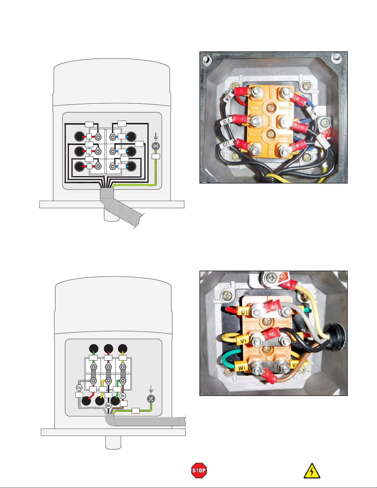
Vertical Spindle Motor Wiring
220V Motor
W1
W2
W1
V1
V1
U2
U1
U1
GND
V2
PE
W3
6
V3
5
U3
V2
U2
4
W2
Figure 104. Vertical spindle motor wiring.
To
Electrical Panel
Page 66
Horizontal Spindle Motor Wiring
220V Motor
U2W2 V2
W2
U1U2V1
U1
U4
V2
V1 W1
V4
W4
Model G0827 (Mfd. Since 11/17)
W1
PE
GND
Figure 105. Horizontal spindle motor wiring.
To
Electrical Panel
Page 66
READ ELECTRICAL SAFETY
ON PAGE 63!
-69-
Page 72

Coolant Pump Wiring
Coolant Pump
To
Electrical Panel
Page 66
To
Electrical Panel
Page 66
GND
U5
PE
V5
W5
DRO Wiring
X
Y
Z
DRO
Figure 106. Coolant pump wiring.
X-Axis Scale 650mm
Y-Axis Scale 300mm
Z-Axis Scale 500mm
(Viewed from Behind)
-70 -
READ ELECTRICAL SAFETY
ON PAGE 63!
Figure 107. DRO wiring.
Model G0827 (Mfd. Since 11/17)
Page 73

SECTION 9: PARTS
Vertical Gearbox
60-1
60-4
60-2
60-5
60-6
We do our best to stock
replacement parts when possible, but we cannot guarantee that all parts shown
are available for purchase.
Call (800) 523-4777 or visit
www.grizzly.com/parts to
check for availability.
4
5
9
8
21
7
6
5
4
3
3
22
40
17
18
19
20
23
19
37
60-3
10
17
62
63
11
12
15
14
61
13
34
60
28
29
17
25
26
27
24
16
54
55
17
30
19
31
32
33
19
17
59
58
57
17
19
56
34
35
36
37
2
41
42
46
49
47
44
45
50
51
48
Model G0827 (Mfd. Since 11/17)
43
39
38
41
51
52
49
50
48
1
53
BUY PARTS ONLINE AT GRIZZLY.COM !
Scan QR code to visit our Parts Store.
45
47
43
44
46
38
39
40
42
-71-
Page 74

Vertical Gearbox Parts
REF PART # DESCRIPTION REF PART # DESCRIPTION
1 P0827001 GEARBOX 36 P0827036 FLANGE BOLT M10-1.5 X 12
2 P0827002 COLLAR 37 P0827037 LIFT FORK
3 P0827003 OIL SEAL FB 45 X 62 X 8 38 P0827038 ROCKER ARM
4 P0827004 BALL BEARING 6009-2RS 39 P0827039 EXT RETAINING RING 10MM
5 P0827005 EXT RETAINING RING 48MM 40 P0827040 ROLL PIN 5 X 30
6 P0827006 GEAR 50T 41 P0827041 SPEED SPINDLE
7 P0827007 GEAR 34T 42 P0827042 O-RING 12 X 2
8 P0827008 SPINDLE SHAFT 43 P0827043 O-RING 20 X 2
9 P0827009 KEY 8 X 8 X 50 44 P0827044 FLAT HD SCR M5-.8 X 12
10 P0827010 GEARBOX COVER 45 P0827045 HIGH/LOW GEAR PLATE
11 P0827011 SET SCREW M16-1.5 X 10 46 P0827046 FIXED HANDLE 20 X 60, M8-1.25 X 8
12 P0827012 ROTOR GUARD 47 P0827047 ROLL PIN 5 X 50
13 P0827013 CAP SCREW M5-.8 X 15 48 P0827048 HIGH/LOW GEAR HUB
14 P0827014 LOCK WASHER 12MM 49 P0827049 STEEL BALL 6MM
15 P0827015 HEX BOLT M12-1.75 X 40 50 P0827050 COMPRESSION SPRING 6 X 30
16 P0827016 DRIVE SHAFT END CAP 51 P0827051 SET SCREW M8-1.25 X 8
17 P0827017 BALL BEARING 6204-2RS 52 P0827052 OIL SIGHT GLASS M18-1.5 X 12
18 P0827018 GEAR 44T 53 P0827053 DRIVE SHAFT END CAP
19 P0827019 EXT RETAINING RING 25MM 54 P0827054 CENTER SHAFT END CAP
20 P0827020 DRIVE SHAFT (REAR) 55 P0827055 REAR SHAFT END CAP
21 P0827021 GEAR 40T 56 P0827056 CAP SCREW M10-1.5 X 30
22 P0827022 GEAR 24T 57 P0827057 KEY 8 X 8 X 40
23 P0827023 KEY 8 X 8 X 15 58 P0827058 SET SCREW M8-1.25 X 10
24 P0827024 DRIVE SHAFT (CENTER) 59 P0827059 GEAR 20T
25 P0827025 GEAR 33T 60 P0827060 MOTOR 2HP 220V 3-PH
26 P0827026 SPACER 60-1 P0827060-1 MOTOR FAN COVER
27 P0827027 GEAR 28T 60-2 P0827060-2 MOTOR FAN
28 P0827028 GEAR 47T 60-3 P0827060-3 MOTOR JUNCTION BOX
29 P0827029 SPACER 60-4 P0827060-4 BALL BEARING 6206ZZ (FRONT)
30 P0827030 GEAR 24T 60-5 P0827060-5 BALL BEARING 6206ZZ (REAR)
31 P0827031 DRIVE SHAFT (FRONT) 60-6 P0827060-6 MOTOR CORD 14G 6W 72"
32 P0827032 GEAR 42T 61 P0827061 FLAT WASHER 12MM
33 P0827033 GEAR 23T 62 P0827062 RIVET 3.5MM BLIND
34 P0827034 SET SCREW M8-1.25 X 10 63 P0827063 COVER PLATE, STEEL
35 P0827035 KEY 8 X 8 X 15
-72-
BUY PARTS ONLINE AT GRIZZLY.COM !
Scan QR code to visit our Parts Store.
Model G0827 (Mfd. Since 11/17)
Page 75

156
160
Vertical Spindle
155
154
157
158
148
113
112
111
110
108
105
159
114
149
115
150
116
161
109
117
118
151
142
141
140
139
119
120
101
152
153
102
103
137
138
136
121
122
123
124
106
104
146
147
107
Model G0827 (Mfd. Since 11/17)
145
144
143
125
126
127
BUY PARTS ONLINE AT GRIZZLY.COM !
128
Scan QR code to visit our Parts Store.
129
130
131
132
134
133
135
-73 -
Page 76

Vertical Spindle Parts
REF P ART # DESCRIPTI ON REF P ART # DESCRIPTI ON
101 P0827101 HEADSTOCK 132 P0827132 LEVER HUB END CAP
102 P0827102 GEAR 50T 133 P0827133 CAP SCREW M6-1 X 6
103 P0827103 CAP SCREW M6-1 X 75 134 P0827134 DOWNFEED SELECTI O N SHAFT M16-2
104 P0827104 SET SCREW M5-.8 x 6 135 P0827135 FIXED HANDLE 20 X 60, M8-1.25 X 8
105 P0827105 SET SCREW M5-.8 X 6 DOG-PT 136 P0827136 BEARING CAP
106 P0827106 VERTICAL SPINDLE R8 137 P0827137 CAP SCREW M6-1 X 12
107 P0827107 TAPERED ROLLER BEARING 32010 138 P0827138 BALL BEARING 6002-2RS
108 P0827108 SLEEVE 139 P0827139 FINE DOWNFEED WORM S HAFT
109 P0827109 BALL OILER 8MM PRESS-IN 140 P0827140 BALL BEARING 6002-2RS
110 P0827110 RUBBER WASHER 90MM 141 P0827141 WORM SHAFT BRACKET
111 P0827111 BALL BEARING 6009-2RS 142 P0827142 CAP SCREW M6-1 X 20
112 P0827112 EXT TOOTH WASHER 40MM 143 P0827143 THUMB S CREW M6-1 X 16
113 P0827113 SPANNER NUT M40-1 . 5 144 P0827144 FINE DOWNFEED GRA DUATE D DI AL
114 P0827114 CAP SCREW M4-.7 X 8 145 P0827145 SET SCREW M6-1 X 8
115 P0827115 RETURN SPRI NG CAP 146 P0827146 HANDWHEEL TYPE-8 100D X 14B-S X M6-1
116 P0827116 RETURN COIL SPRI NG 147 P0827147 FIXED HANDLE 16 X 63, M6-1 X 10
117 P0827117 SPRING BASE 148 P0827148 ADJUSTABLE HANDLE M10-1.5 X 123, 43L
118 P0827118 SET SCREW M8-1.25 X 16 149 P0827149 OUTER QUILL LOCK SLEEVE
119 P0827119 SET SCREW M8-1.25 X 16 150 P0827150 INNER QUILL LOCK SLEEVE
120 P0827120 DOWNFEED GEAR HOUS I NG 151 P0827151 SET SCREW M10-1.5 X 10
121 P0827121 CAP SCREW M8-1.25 X 25 152 P0827152 COVER PLATE
122 P0827122 ROLL PIN 6 X 25 153 P0827153 CAP SCREW M5-.8 X 10
123 P0827123 FEED SHAFT 154 P0827154 GEARBOX MOUNTING PLATE
124 P0827124 KEY 8 X 8 X 38 155 P0827155 CAP SCREW M10-1.5 X 30
125 P0827125 HELICAL GEAR 50T 156 P0827156 ROLL PIN 8 X 25
126 P0827126 EXT RETAINI NG RI NG 30MM 157 P0827157 HEADSTOCK ALIGNMENT PIN M6-1 X 55
127 P0827127 THUMB SCREW M6-1 X 1 2 158 P0827158 FLAT WAS HER 6 MM
128 P0827128 COARSE DOWNFEED G RADUA TED DIAL 159 P0827159 LOCK WASHER 6MM
129 P0827129 COARSE DOWNFEED LEVER HUB 160 P0827160 HEX NUT M6 -1
130 P0827130 LEVER HANDLE 200L, M12-1.75 X 15 161 P0827161 VERT. SPINDLE DRAWBAR 7/16-20 X 18-1/8
131 P0827131 COMPRESSION SPRING 2 X 22 X 61
-74 -
BUY PARTS ONLINE AT GRIZZLY.COM !
Scan QR code to visit our Parts Store.
Model G0827 (Mfd. Since 11/17)
Page 77

Ram
REF PART # DESCRIPTION REF PART # DESCRIPTION
220
220
204
226
219
225
224
222
218
217
216
214
215
221
202
206
222
203
201
212
211
212
227
221
211
213
207
228
208
223
230
205
209
232
233
207
222
231
229
234
206
208
210
201 P0827201 TURRET 218 P0827218 THRUST BEARING 51101
202 P0827202 RAM 219 P0827219 SET SCREW M8-1.25 X 16
203 P0827203 TURRET BASE 220 P0827220 CAP SCREW M16-2 X 65
204 P0827204 HEADSTOCK MOUNT 221 P0827221 RAM TOP COVER PLATE
205 P0827205 RAM GIB 222 P0827222 PHLP HD SCR M6-1 X 10
206 P0827206 GIB ADJUSTING SCREW 223 P0827223 RAM REAR COVER PLATE
207 P0827207 LOCK BUSHING 224 P0827224 T-BOLT M16-2 X 60
208 P0827208 ADJUSTABLE HANDLE M10-1.5 X 25, 60L 225 P0827225 LOCK WASHER 16MM
209 P0827209 GEAR SHAFT 15T 226 P0827226 HEX NUT M16-2
210 P0827210 BUSHING 227 P0827227 SET SCREW M6-1 X 12
211 P0827211 LOCK WASHER 16MM 228 P0827228 HORIZONTAL ARBOR BRACKET
212 P0827212 HEX BOLT M16-2 X 80 229 P0827229 BUSHING (BRASS)
213 P0827213 BALL OILER 8MM PRESS-IN 230 P0827230 SET SCREW M8-1.25 X 16
214 P0827214 WORM SHAFT 231 P0827231 BALL OILER 8MM PRESS-IN
215 P0827215 KEY 4 X 4 X 20 232 P0827232 HEX BOLT M16-2 X 220
216 P0827216 WORM GEAR 233 P0827233 FLAT WASHER 16MM
217 P0827217 THRUST BEARING 51102 234 P0827234 HEX NUT M16-2
Model G0827 (Mfd. Since 11/17)
BUY PARTS ONLINE AT GRIZZLY.COM !
Scan QR code to visit our Parts Store.
-75-
Page 78
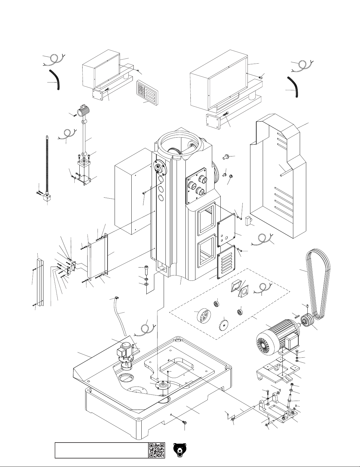
Base & Column
384
340
377
379
354
339
366
370
374
368
367
375
344
349
376
347
369
372
371
348
373
363
362
364
343
346
345
312
358
365
360
359
342
356
361
357
353
315
314
313
341
352
355
311
382
302
319-1
304
319-3
319-2
356
309
308
310
383
319-4
303
305
383
319-5
303
380
355
350
319-6
319
385
381
306
307
351
316
318
320
-76-
336
386
BUY PARTS ONLINE AT GRIZZLY.COM !
Scan QR code to visit our Parts Store.
338
337
383
338
335
301
334
321
322
323
324
325
326
327
334
333
328
332
333
330
329
334
334
333
331
Model G0827 (Mfd. Since 11/17)
317
Page 79

Base & Column Parts
REF PART # DESCRIPTION REF PART # DESCRIPTION
301 P0827301 BASE 341 P0827341 COOLANT HOSE 1/2" X 36"
302 P0827302 COLUMN 342 P0827342 COOLANT HOSE CLAMP 3/4"
303 P0827303 PHLP HD SCR M6-1 X 12 343 P0827343 WORK LIGHT
304 P0827304 COLUMN SIDE COVER, LOWER RIGHT 344 P0827344 LED BULB 24W BI-PIN
305 P0827305 COLUMN SIDE COVER, UPPER RIGHT 345 P0827345 WORK LIGHT BRACKET, STEEL
306 P0827306 REAR ACCESS PANEL 346 P0827346 CAP SCREW M5-.8 X 10
307 P0827307 HEX BOLT M10-1.5 X 155 347 P0827347 CAP SCREW M6-1 X 10
308 P0827308 OIL SIGHT GLASS M18-1.5 X 12 348 P0827348 FLAT WASHER 6MM
309 P0827309 OIL DRAIN PLUG M10-1.5 X 8 349 P0827349 WORK LIGHT PWR CORD 18G 2W 36"
310 P0827310 OIL FILL PLUG M16-1.5 X 8 350 P0827350 LIMIT SWITCH CHINT XBLXW-W11Q1
311 P0827311 CAP SCREW M8-1.25 X 16 351 P0827351 LIMIT SWITCH CORD 18G 2W 36"
312 P0827312 ELECTRICAL CABINET 352 P0827352 DRO DISPLAY ASSEMBLY
313 P0827313 LOCK WASHER 16MM 353 P0827353 DRO CONTROL BOX W/SWING ARM
314 P0827314 FLAT WASHER 16MM 354 P0827354 DRO POWER CORD CONDUIT
315 P0827315 CAP SCREW M16-2 X 60 355 P0827355 BUTTON HD CAP SCR M4-.7 X 6
316 P0827316 V-BELT A-1422 356 P0827356 CAP SCREW M8-1.25 X 20
317 P0827317 MOTOR PULLEY 357 P0827357 Z-AXIS DRO SCALE BRACKET, ALUM
318 P0827318 SET SCREW M8-1.25 X 16 358 P0827358 CAP SCREW M5-.8 X 25
319 P0827319 HORIZ. SPINDLE MOTOR 3HP 220V 3-PH 359 P0827359 LOCK WASHER 5MM
319-1 P0827319-1 MOTOR FAN COVER 360 P0827360 FLAT WASHER 5MM
319-2 P0827319-2 MOTOR FAN 361 P0827361 SET SCREW M5-.8 X 16
319-3 P0827319-3 BALL BEARING 6206ZZ (FRONT) 362 P0827362 Z-AXIS DRO SCALE 450MM
319-4 P0827319-4 BALL BEARING 6206ZZ (REAR) 363 P0827363 CAP SCREW M5-.8 X 30
319-5 P0827319-5 JUNCTION BOX 364 P0827364 LOCK WASHER 5MM
319-6 P0827319-6 MOTOR PWR CORD 14G 6W 36" 365 P0827365 FLAT WASHER 5MM
320 P0827320 KEY 8 X 8 X 50 366 P0827366 Z-AXIS SENSOR BRACKET
321 P0827321 HEX BOLT M10-1.5 X 30 367 P0827367 CAP SCREW M4-.7 X 14
322 P0827322 LOCK WASHER 10MM 368 P0827368 LOCK WASHER 4MM
323 P0827323 FLAT WASHER 10MM 369 P0827369 FENDER WASHER 4MM
324 P0827324 MOTOR MOUNT PLATE 370 P0827370 KNEE BRACKET ALUM
325 P0827325 HEX NUT M12-1.75 371 P0827371 CAP SCREW M5-.8 X 16
326 P0827326 LOCK WASHER 12MM 372 P0827372 LOCK WASHER 5MM
327 P0827327 ADJUSTING BOLT M12-1.75 X 130 373 P0827373 FLAT WASHER 5MM
328 P0827328 MOTOR BASE PLATE 374 P0827374 CAP SCREW M6-1 X 20
329 P0827329 FLAT WASHER 10MM 375 P0827375 LOCK WASHER 6MM
330 P0827330 HEX BOLT M10-1.5 X 40 376 P0827376 FENDER WASHER 6MM
331 P0827331 SHORT SHAFT 12 X 58L 377 P0827377 Z-AXIS DRO SCALE COVER
332 P0827332 LONG SHAFT 12 X 220L 378 P0827378 CAP SCREW M4-.7 X 10
333 P0827333 LOCK WASHER 12MM 379 P0827379 FLAT WASHER 4MM
334 P0827334 COTTER PIN 2.5 X 16 380 P0827380 POWER CONTROL BOX W/SWING ARM
335 P0827335 FLANGE BOLT M16-1.5 X 12 381 P0827381 POWER CONTROL BOX CORD CONDUIT
336 P0827336 COOLANT PUMP 40W, 220V, 3-PH 382 P0827382 COOLANT PUMP PWR CORD 18G 2W 36"
337 P0827337 COOLANT DRAIN SCREEN 383 P0827383 FLAT WASHER 6MM
338 P0827338 CAP SCREW M6-1 X 12 384 P0827384 DRO CONTROL BOX POWER CORD
339 P0827339 COOLANT NOZZLE 385 P0827385 POWER CONTROL BOX POWER CORD
340 P0827340 CAP SCREW M6-1 X 30 386 P0827386 SPLASH GUARD
Model G0827 (Mfd. Since 11/17)
BUY PARTS ONLINE AT GRIZZLY.COM !
Scan QR code to visit our Parts Store.
-77-
Page 80

Horizontal Spindle
468
467
406
465
407
403
411
408
402
409
404
401
410
412
423
404
413
433
407
414
434
424
417
405
419
420
418
416
416
415
426
422
420
425
436
422
435
420
405
421
420
441
422
442
420
421
437
421
443
422
438
422
444
427
429
445
428
449
446
430
439
447
431
448
432
440
450
427
463
461
462
460
459
455
458
466
456
452
454
453
451
457
464
465
-78 -
BUY PARTS ONLINE AT GRIZZLY.COM !
Scan QR code to visit our Parts Store.
Model G0827 (Mfd. Since 11/17)
Page 81

Horizontal Spindle Parts
REF P ART # DE SCRIPTION REF PART # DE SCRIPTIO N
401 P0827401 SET SCREW M5-.8 X 6 435 P0827435 KEY 10 X 10 X 36
402 P0827402 SET SCREW M5-.8 X 8 DOG-PT 436 P0827436 PLUG
403 P0827403 HORI ZONTAL SPINDLE R8 437 P0827437 E XT RETAINING RI NG 34MM
404 P0827404 KEY 12 X 12 X 45 438 P0827438 COMBO GEAR 27/ 32/22T
405 P0827405 CAP SCREW M8-1.25 X 25 439 P0827439 SPLI NED SHAFT
406 P0827406 INBOARD END COVER 440 P0827440 KEY 10 X 10 X 50
407 P0827407 GASKET 441 P0827441 O-RING 30 X 2.65
408 P0827408 TAPERED ROLLER BEARING 32011-P5 442 P0827442 O-RING 45 X 3.55
409 P0827409 GEAR 26T 443 P0827443 GASKET
410 P0827410 GEAR 57T 444 P0827444 FLANGE
411 P0827411 SET SCREW M10-1.5 X 16 445 P0827445 CAP SCREW M8-1. 25 X 20
412 P0827412 RETAI NING RI NG 446 P0827446 BALL BEARING 6307-2RS
413 P0827413 TAPERED ROLLER BEARING 30308-P5 447 P0827447 COVER
414 P0827414 END COVER 448 P0827448 CAP SCREW M6-1 X 20
415 P0827415 BUSHI NG 449 P0827449 BUSHI NG
416 P0827416 SPA NNER NUT M39-1.5 450 P0827450 HORIZ. SPINDLE PULLEY
417 P0827417 OUTBOARD END COVER 451 P0827451 INDICATO R PLATE
418 P0827418 CAP SCREW M5-.8 X 12 452 P0827452 SET SCREW M10-1.5 X 10
419 P0827419 HORIZ. SPINDLE DRAWBAR 7/16-20 X 16-1/ 2 453 P0827453 COMPRESSION SPRING
420 P0827420 SET SCREW M6-1 X 10 454 P0827454 STEEL BALL 8MM
421 P0827421 PLUG 455 P0827455 HORIZONTAL SPINDLE DIAL
422 P0827422 BALL BEARING 6205-2RS 456 P0827456 TAPER PIN 4 X 30
423 P0827423 SPLINED SHAFT 457 P0827457 BUSHI NG
424 P0827424 COMBO GEAR 48/17T 458 P0827458 O-RING 11.2 X 2. 65
425 P0827425 COMBO GEAR 50/33T 459 P0827459 SHAFT
426 P0827426 PLUG 460 P0827460 TAPER PIN 4 X 30
427 P0827427 EXT RE TAINING RI NG 35MM 461 P0827461 ROCKE R ARM
428 P0827428 GEAR 38T 462 P0827462 EXT RE TAINING RI NG 12MM
429 P0827429 SET SCREW M8-1.25 X 14 463 P0827463 SHIFTI NG FORK
430 P0827430 RETAI NING RI NG 464 P0827464 VERTICAL GEAR CHANGE COVER
431 P0827431 GEAR 33T 465 P0827465 CAP SCREW M6-1 X 20
432 P0827432 GEAR 26T 466 P0827466 GASKET
433 P0827433 GEAR 43T 467 P0827467 GASKET
434 P0827434 SHAFT 468 P0827468 COLUMN SIDE COVER, LEFT
Model G0827 (Mfd. Since 11/17)
BUY PARTS ONLINE AT GRIZZLY.COM !
Scan QR code to visit our Parts Store.
-79 -
Page 82

Table
502
501
515
513
549
550
503
502
539
551
504
505
517
513
538
591
506
552
516
537
514
513
590
507
508
512
516
512
511
536
556
513
515
510
528
535
558
509
559
557
528
564
552
518
567
565
524
534
562
533
529
566
520
563
525
536
560
520
526
535
561
501
521
503
530
535
519
504
537
512
536
521
594
572
531
522
595
523
532
535
532
528
523
536
576
505
571
539
540
577
582
588
587
586
506
569
541
507
542
583
574
508
575
543
527
528
548
507508
544
578
589
584
506
545
547
596
568
573
570
593
581
580
585
545
546
505
546
548
544
579
594
592
554
504
568
595
553
555
503
502
501
543
-80-
BUY PARTS ONLINE AT GRIZZLY.COM !
Scan QR code to visit our Parts Store.
Model G0827 (Mfd. Since 11/17)
Page 83

Table Parts
REF PART # DESCRIPTION REF PART # DESCRIPTION
501 P0827501 SHOULDER SCR M8-1.25 X 13, 10 X 59 549 P0827549 RETAINER PLATE
502 P0827502 HANDLE W/OUT SHAFT 18 X 65, 10 550 P0827550 CAP SCREW M6-1 X 16
503 P0827503 ACORN NUT M12-1.75 551 P0827551 BUSHING
504 P0827504 LOCK WASHER 12MM 552 P0827552 BALL OILER 8MM PRESS-IN
505 P0827505 HANDWHEEL TYPE-10 160D X 22B-N X M8-1.25 553 P0827553 COOLANT HOSE CONNECTOR 1/2" NPT
506 P0827506 COMPRESSION SPRING 1.7 X 26 X 17 554 P0827554 COOLANT HOSE CLAMP 3/4"
507 P0827507 BUSHING 555 P0827555 COOLANT HOSE 1/2" X 36"
508 P0827508 HANDWHEEL GEAR 4T 556 P0827556 LIMIT SWITCH ASONG 1516 V52 AN
509 P0827509 BUSHING 557 P0827557 FLAT WASHER 8MM
510 P0827510 GRADUATED DIAL 558 P0827558 CAP SCREW M8-1.25 X 20
511 P0827511 CAP SCREW M6-1 X 16 559 P0827559 PHLP HD SCR M3-.5 X 30
512 P0827512 KEY 5 X 5 X 20 560 P0827560 TRAVEL STOP SHAFT
513 P0827513 THRUST BEARING 51103 561 P0827561 COMPRESSION SPRING 1.2 X 11 X 33
514 P0827514 X-AXIS LEADSCREW BRACKET (L) 562 P0827562 T-NUT M6-1
515 P0827515 CAP SCREW M8-1.25 X 25 563 P0827563 TRAVEL STOP
516 P0827516 ROLL PIN 6 X 25 564 P0827564 E-CLIP 8MM
517 P0827517 Y-AXIS LEADSCREW BRACKET 565 P0827565 CAP SCREW M6-1 X 16
518 P0827518 Y-AXIS LEADSCREW 566 P0827566 FLAT WASHER 6MM
519 P0827519 BEARING HOUSING 567 P0827567 FENDER WASHER 8MM
520 P0827520 TAPER PIN 6 X 40 568 P0827568 POWER FEED PWR CORD 18G 3W 72"
521 P0827521 KEY 6 X 6 X 22 569 P0827569 X-AXIS DRO SCALE 800MM
522 P0827522 THREADED BUSHING 570 P0827570 CAP SCREW M5-.8 X 30
523 P0827523 SPANNER NUT M36-1.5 571 P0827571 LOCK WASHER 5MM
524 P0827524 SADDLE 572 P0827572 FLAT WASHER 5MM
525 P0827525 CLIPPED WASHER 8MM 573 P0827573 X-AXIS DRO SCALE COVER
526 P0827526 FLANGE SCREW M8-1.25 X 16 574 P0827574 CAP SCREW M5-.8 X 10
527 P0827527 LONGITUDINAL GIB 575 P0827575 FLAT WASHER 5MM
528 P0827528 GIB ADJUSTING SCREW 576 P0827576 SPACER 7 X 18 X 15 ROUND
529 P0827529 CROSS GIB 577 P0827577 SQUARE BLOCK 35 X 27 X 10
530 P0827530 BEARING HOUSING 578 P0827578 Y-AXIS SENSOR BRACKET
531 P0827531 BUSHING 579 P0827579 CAP SCREW M6-1 X 65
532 P0827532 BEARING ADJUSTMENT SCR M8-1.25 X 22 580 P0827580 LOCK WASHER 6MM
533 P0827533 X-AXIS LEADSCREW 581 P0827581 FENDER WASHER 6MM
534 P0827534 TABLE 582 P0827582 Y-AXIS SENSOR MOUNTING PLATE
535 P0827535 LOCK BUSHING 583 P0827583 CAP SCREW M6-1 X 20
536 P0827536 ADJUSTABLE HANDLE M10-1.5 X 40, 60L 584 P0827584 LOCK WASHER 6MM
537 P0827537 FELT GASKET 585 P0827585 FENDER WASHER 6MM
538 P0827538 WAY WIPER FRONT 586 P0827586 CAP SCREW M4-.7 X 14
539 P0827539 PHLP HD SCR M5-.8 X 12 587 P0827587 LOCK WASHER 4MM
540 P0827540 WAY WIPER COVER BACK 588 P0827588 FENDER WASHER 4MM
541 P0827541 X-AXIS LEADSCREW BRACKET (R) 589 P0827589 SET SCREW M5-.8 X 16
542 P0827542 CAP SCREW M10-1.5 X 25 590 P0827590 INDICATOR SCALE
543 P0827543 POWER FEED UNIT ASONG AS-235 220V 591 P0827591 BLIND RIVET 3.5MM
544 P0827544 LOCK WASHER 6MM 592 P0827592 DRAIN SCREEN
545 P0827545 CAP SCREW M6-1 X 25 593 P0827593 CAP SCREW M4-.7 X 6
546 P0827546 BEVEL GEAR 594 P0827594 DRO SCALE COVER END CAP
547 P0827547 X-AXIS GRADUATED DIAL 595 P0827595 PHLP HD SCR M3-.5 X 5
548 P0827548 SPANNER NUT 1-1/4-20 596 P0827596 Y-AXIS GRADUATED DIAL
Model G0827 (Mfd. Since 11/17)
BUY PARTS ONLINE AT GRIZZLY.COM !
Scan QR code to visit our Parts Store.
-81-
Page 84
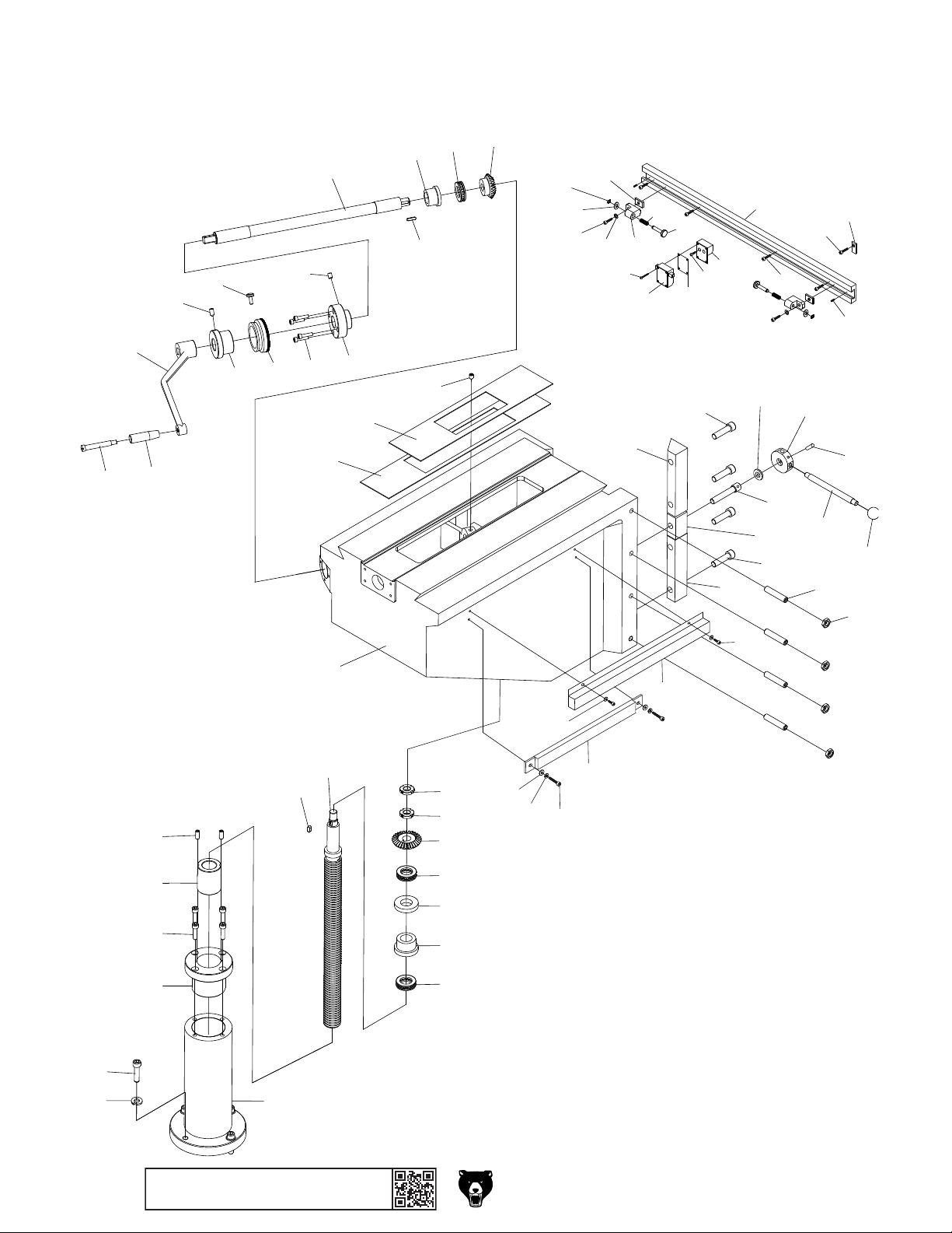
618
632
644
630
631
629
627
628
626
624
625
603
Knee Spindle
619
620
621
622
623
645
602
664
667
665
662
666
656
635
663
655
661
660
658
636
659
657
653
640
637
669
654
654
668
641
642
639
643
610
609
608
607
612
601
611
617
617
616
613
615
614
613
649
648
652
647
646
650
638
651
636
633
634
606
605
-82-
604
BUY PARTS ONLINE AT GRIZZLY.COM !
Scan QR code to visit our Parts Store.
Model G0827 (Mfd. Since 11/17)
Page 85

Knee Spindle Parts
REF PART # DESCRIPTION REF PART # DESCRIPTION
601 P0827601 KNEE 636 P0827636 CAP SCREW M12-1.75 X 45
602 P0827602 UPPER WAY COVER 637 P0827637 Z-AXIS GIB MIDDLE
603 P0827603 LOWER WAY COVER 638 P0827638 Z-AXIS GIB BOTTOM
604 P0827604 Z-AXIS LEADSCREW HOUSING 639 P0827639 LOCK SLEEVE SCREW M12-1.75 X 65
605 P0827605 LOCK WASHER 10MM 640 P0827640 LOCK SLEEVE FLAT WASHER 12MM
606 P0827606 CAP SCREW M10-1.5 X 40 641 P0827641 LOCK SLEEVE
607 P0827607 Z-AXIS LEADSCREW COLLAR 642 P0827642 TAPER PIN 5 X 40
608 P0827608 CAP SCREW M8-1.25 X 30 643 P0827643 STUD DE M10-1.5 X 12, 12 X 150
609 P0827609 THREADED BUSHING 644 P0827644 KNOB M10-1.5 D25 BALL
610 P0827610 SET SCREW M8-1.25 X 20 645 P0827645 SET SCREW M8-1.25 X 12
611 P0827611 Z-AXIS LEADSCREW 646 P0827646 Y-AXIS DRO SCALE 300MM
612 P0827612 KEY 6 X 6 X 12 647 P0827647 CAP SCREW M5-.8 X 30
613 P0827613 THRUST BEARING 51105 648 P0827648 LOCK WASHER 5MM
614 P0827614 BEARING SEAT 649 P0827649 FLAT WASHER 5MM
615 P0827615 ADJUSTMENT BUSHING 650 P0827650 Y-AXIS DRO SCALE COVER
616 P0827616 CONICAL GEAR 36T 651 P0827651 CAP SCREW M5-.8 X 10
617 P0827617 SPANNER NUT M16-1.5 652 P0827652 FLAT WASHER 5MM
618 P0827618 CONICAL GEAR 18T 653 P0827653 LIMIT SWITCH BRACKET, 415MM
619 P0827619 THRUST BEARING 51105 654 P0827654 CAP SCREW M5-.8 X 10
620 P0827620 BEARING SEAT 655 P0827655 LIMIT SWITCH ASSY ASONG 1516 V52 AN
621 P0827621 Z-AXIS CRANKSHAFT 656 P0827656 PHLP HD SCR M3-.5 X 30
622 P0827622 KEY 5 X 5 X 18 657 P0827657 LIMIT SWITCH MOUNTING BRACKET
623 P0827623 CRANKSHAFT BRACKET 658 P0827658 RUBBER GASKET 42 X 56
624 P0827624 BALL OILER 8MM PRESS-IN 659 P0827659 CAP SCREW M6-1 X 22
625 P0827625 CAP SCREW M6-1 X 25 660 P0827660 TRAVEL STOP SHAFT
626 P0827626 Z-AXIS GRADUATED DIAL 661 P0827661 COMPRESSION SPRING 1.2 X 11 X 33
627 P0827627 THUMB SCREW M5-.8 X 12 662 P0827662 T-NUT M6-1
628 P0827628 CRANKSHAFT BUSHING 663 P0827663 TRAVEL STOP
629 P0827629 SET SCREW M8-1.25 X 16 664 P0827664 E-CLIP 8MM
630 P0827630 Z-AXIS CRANK 665 P0827665 CAP SCREW M6-1 X 16
631 P0827631 HANDLE W/OUT SHAFT 22 X 75, 12 666 P0827666 FLAT WASHER 6MM
632 P0827632 SHOULDER SCR M10-1.5 X 12, 12 X 88 667 P0827667 FENDER WASHER 8MM
633 P0827633 SET SCREW M12-1.75 X 60 668 P0827668 SET SCREW M5-.8 X 12
634 P0827634 HEX NUT M12-1.75 669 P0827669 LIMIT SWITCH CORD RETAINER
635 P0827635 Z-AXIS GIB TOP
Model G0827 (Mfd. Since 11/17)
BUY PARTS ONLINE AT GRIZZLY.COM !
Scan QR code to visit our Parts Store.
-83-
Page 86

Electrical Box & Control Panel Components
726
702
705
705
REF PART # DESCRIPTION REF PART # DESCRIPTION
3/L2
5/L3
20
ON
OFF
Test
QF1
716
A1
1L1
3L2 5L3
31NC 43NO
13NO 21NC
KM5 Contactor
Siemens 3TB41 24V
14NO 22NC 32NC 44NO
2T1 4T2 6T3
718
A1
1L1
13NO 21NC
Siemens 3TB41 24V
22E
14NO 22NC 32NC 44NO
2T1 4T2 6T3
A2
723
713
3L2 5L3
KA Contactor
723
31NC 43NO
A2
723
730
730
733
727
LA125H-BE102C
LA125H-BE102C
Minger
(Shown from behind)
Minger
1 2
Minger
1
LA125H-BE101C
731
731
2
734
3 4
Minger
LA125H-BE101C
3 4
Minger
LA125H-BE101C
3 4
12
Minger
LA125H-BE102C
731
731
735
736
Minger
LA125H-BE101C
3 4
Minger
LA125H-BE101C
3 4
Minger
LA125J-11
D206A
705
703
701
724
704
2
4
LW26-20
719
A1
1L1
13NO 21NC
14NO 22NC 32NC 44NO
2T1 4T2 6T3
1
3
LW26-25
PE 0 220 230 380 400
Transformer
10
14
6
16
12
8
720
3L2 5L3
31NC 43NO
KM1 Contactor
Siemens 3TB41 24V
22E
A2
5
7
721
JBK5-160VA
0 24
737
720
A1
1L1
3L2 5L3
13NO 21NC
KM2 Contactor
Siemens 3TB41 24V
22E
14NO 22NC 32NC 44NO
2T1 4T2 6T3
723
DZ47-60
C2
QF2
717
1/L1
21 22 13 14
25
23
ON
OFF
20-25A
NS2-25
CHINT
2/T1 4/T2 6/T3
723
725
TC
714
712
720 720 720 720
A1
1L1
31NC 43NO
13NO 21NC
Siemens 3TB41 24V
22E 22E
14NO 22NC 32NC 44NO
2T1 4T2 6T3
A2
3L2 5L3
KM3 Contactor
31NC 43NO
A1
1L1
3L2 5L3
13NO 21NC
KM4 Contactor
Siemens 3TB41 24V
22E
14NO 22NC 32NC 44NO
2T1 4T2 6T3
A2
31NC 43NO
A2
725
722
725
723
711
740739738
710
701 P0827701 ELECTRICAL BOX W/DOOR 722 P0827722 TERMINAL BAR 1P
702 P0827702 STRAIN RELIEF TYPE-5 PG8 723 P0827723 PHLP HD SCR M4-.7 X 6
703 P0827703 CONDUIT 10MM 724 P0827724 ELECTRICAL BOX MOUNTING PLATE
704 P0827704 STRAIN RELIEF TYPE-5 PG10 725 P0827725 WIRE LOOM 10"
705 P0827705 CONDUIT 12MM 726 P0827726 ELECTRICAL BOX LOCK W/KEYS
710 P0827710 STRAIN RELIEF TYPE-3 PG10 727 P0827727 CONTROL PANEL FACEPLATE
711 P0827711 STRAIN RELIEF TYPE-3 PG12 730 P0827730 BUTTON SWITCH MINGER LA125H 22MM RED
712 P0827712 WIRE LOOM 12" 731 P0827731 BUTTON SWITCH MINGER LA125H 22MM GRN
713 P0827713 WIRE LOOM 18" 733 P0827733 PUMP SWITCH MINGER LA125H 22MM
714 P0827714 TRANSFORMER JBK5-160V 734 P0827734 E-STOP BUTTON MINGER LA125H 22MM
716 P0827716 OL RELAY CHINT NS2-25 20-25A 735 P0827735 POWER BUTTON MINGER LA125J-11D206A
717 P0827717 CIRCUIT BREAKER CHINT DZ4760 C2 2P 736 P0827736 POWER CORD 14G 4W 72"
718 P0827718 DIN RAIL 3" 737 P0827737 ROTARY SWITCH CANSEN LW26-20
719 P0827719 DIN RAIL 10" 738 P0827738 HEX NUT M4-.7
720 P0827720 CONTACTOR SIEMENS 3TB41 24V 739 P0827739 FLAT WASHER 4MM
721 P0827721 ROTARY SWITCH CANSEN LW26-25 740 P0827740 BUTTON HD CAP SCR M4-.7 X 6
704
704
723
711 711
-84-
BUY PARTS ONLINE AT GRIZZLY.COM !
Scan QR code to visit our Parts Store.
Model G0827 (Mfd. Since 11/17)
Page 87
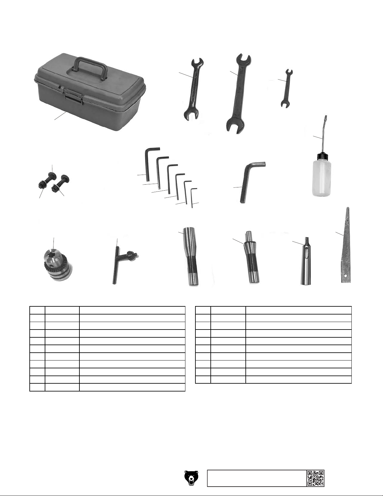
Accessories & Tools
REF PART # DESCRIPTION REF PART # DESCRIPTION
807
801
805
817
806
818
809
810
811
812
802
813
819
814
803
815
820
823
804
822
821
801 P0827801 TOOLBOX 813 P0827813 HEX WRENCH 3MM
802 P0827802 WRENCH 17 X 19MM OPEN-ENDS 814 P0827814 HEX WRENCH 2.5MM
803 P0827803 WRENCH 22 X 24MM OPEN-ENDS 815 P0827815 HEX WRENCH 10MM
804 P0827804 BOTTLE FOR OIL 817 P0827817 DRILL CHUCK B16
805 P0827805 T-BOLT M14-2 X 60 818 P0827818 DRILL CHUCK KEY
806 P0827806 FLAT WASHER 14MM 819 P0827819 SPINDLE SLEEVE R8 X MT#3
807 P0827807 HEX NUT M14-2 820 P0827820 DRILL CHUCK ARBOR R8 X B16
809 P0827809 HEX WRENCH 8MM 821 P0827821 SPINDLE SLEEVE MT#3 X MT#2
810 P0827810 HEX WRENCH 6MM 822 P0827822 DRIFT KEY
811 P0827811 HEX WRENCH 5MM 823 P0827823 WRENCH 8 X 10MM OPEN-ENDS
812 P0827812 HEX WRENCH 4MM
Model G0827 (Mfd. Since 11/17)
BUY PARTS ONLINE AT GRIZZLY.COM !
Scan QR code to visit our Parts Store.
-85-
Page 88
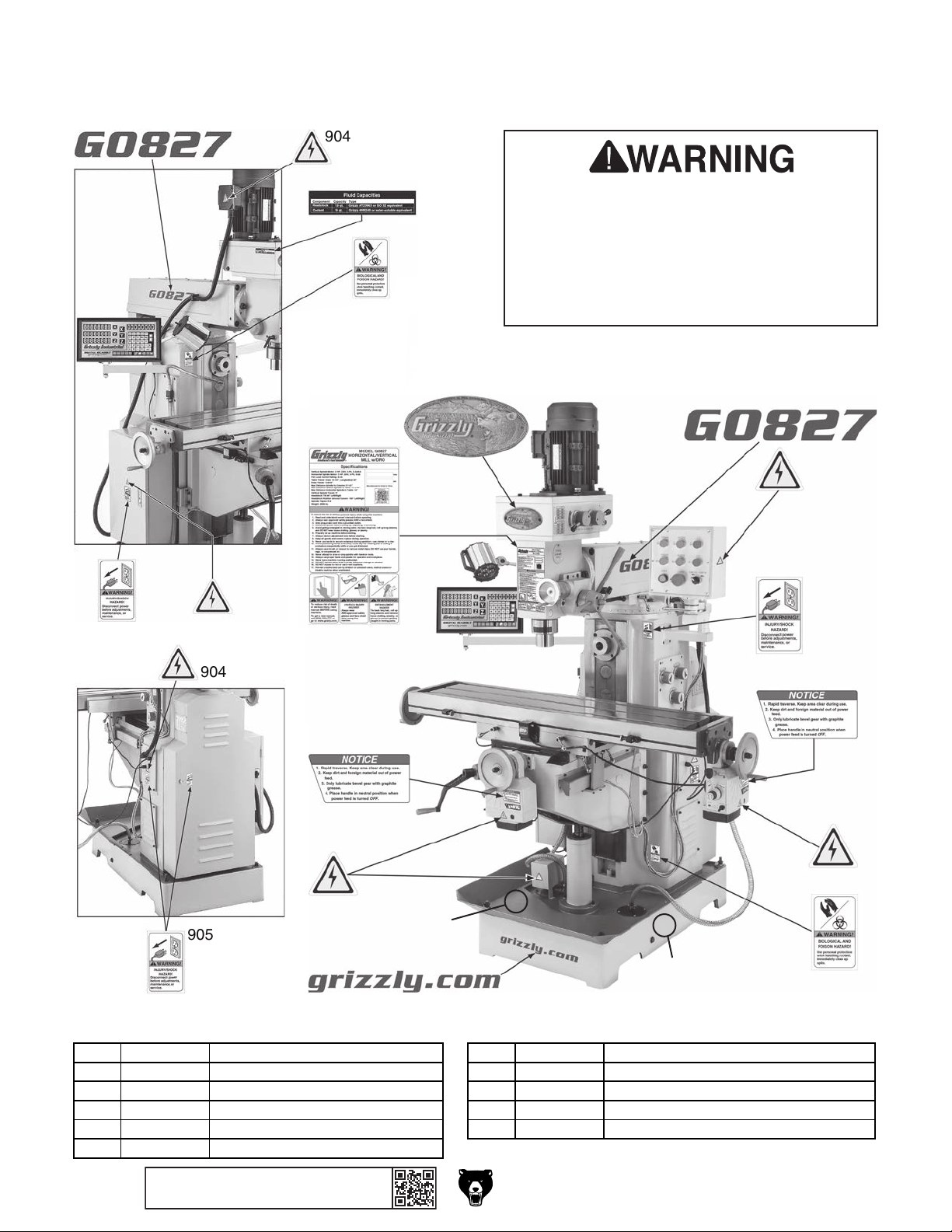
904
903
REF PART # DESCRIPTION REF PART # DESCRIPTION
Labels & Cosmetics
905
904
909
901
907
902
Safety labels help reduce the risk of serious
injury caused by machine hazards. If any
label comes off or becomes unreadable,
the owner of this machine MUST replace
it in the original location before resuming
operations. For replacements, contact (800)
523-4777 or www.grizzly.com.
903
904
905
904
906
904
905
908
901 P0827901 MACHINE ID LABEL 907 P0827907 BIOLOGICAL/POISON WARNING LABEL
902 P0827902 GRIZZLY NAMEPLATE SMALL 908 P0827908 GRIZZLY.COM LABEL
903 P0827903 MODEL NUMBER LABEL 909 P0827909 FLUID CAPACITIES LABEL
904 P0827904 ELECTRICITY WARNING LABEL 910 P0827910 TOUCH-UP PAINT, GRIZZLY BEIGE
905 P0827905 DISCONNECT POWER LABEL 911 P0827911 TOUCH-UP PAINT, GRIZZLY GREEN
906 P0827906 POWER TRAVERSE NOTICE
911
906
904
907
910
-86-
BUY PARTS ONLINE AT GRIZZLY.COM !
Scan QR code to visit our Parts Store.
Model G0827 (Mfd. Since 11/17)
Page 89

WARRANTY CARD
Name _____________________________________________________________________________
Street _____________________________________________________________________________
City _______________________ State _________________________ Zip _____________________
Phone # ____________________ Email _________________________________________________
Model # ____________________ Order # _______________________ Serial # __________________
The following information is given on a voluntary basis. It will be used for marketing purposes to help us develop
better products and services. Of course, all information is strictly confidential.
1. How did you learn about us?
____ Advertisement ____ Friend ____ Catalog
____ Card Deck ____ Website ____ Other:
2. Which of the following magazines do you subscribe to?
____ Cabinetmaker & FDM
____ Family Handyman
____ Hand Loader
____ Handy
____ Home Shop Machinist
____ Journal of Light Cont.
____ Live Steam
____ Model Airplane News
____ Old House Journal
____ Popular Mechanics
3. What is your annual household income?
____ $20,000-$29,000 ____ $30,000-$39,000 ____ $40,000-$49,000
____ $50,000-$59,000 ____ $60,000-$69,000 ____ $70,000+
CUT ALONG DOTTED LINE
4. What is your age group?
____ 20-29 ____ 30-39 ____ 40-49
____ 50-59 ____ 60-69 ____ 70+
5. How long have you been a woodworker/metalworker?
____ 0-2 Years ____ 2-8 Years ____ 8-20 Years ____ 20+ Years
6. How many of your machines or tools are Grizzly?
____ 0-2 ____ 3-5 ____ 6-9 ____10+
____ Popular Science
____ Popular Woodworking
____ Precision Shooter
____ Projects in Metal
____ RC Modeler
____ Rie
____ Shop Notes
____ Shotgun News
____ Today’s Homeowner
____ Wood
____ Wooden Boat
____ Woodshop News
____ Woodsmith
____ Woodwork
____ Woodworker West
____ Woodworker’s Journal
____ Other:
7. Do you think your machine represents a good value? _____ Yes _____No
8. Would you recommend Grizzly Industrial to a friend? _____Yes _____No
9. Would you allow us to use your name as a reference for Grizzly customers in your area?
Note: We never use names more than 3 times. _____Yes _____No
10. Comments: _____________________________________________________________________
_________________________________________________________________________________
_________________________________________________________________________________
_________________________________________________________________________________
Page 90

FOLD ALONG DOTTED LINE
FOLD ALONG DOTTED LINE
Place
Stamp
Here
GRIZZLY INDUSTRIAL, INC.
P.O. BOX 2069
BELLINGHAM, WA 98227-2069
Send a Grizzly Catalog to a friend:
Name_______________________________
Street_______________________________
City______________State______Zip______
TAPE ALONG EDGES--PLEASE DO NOT STAPLE
Page 91

WARRANTY & RETURNS
Grizzly Industrial, Inc. warrants every product it sells for a period of 1 year to the original purchaser from
the date of purchase. This warranty does not apply to defects due directly or indirectly to misuse, abuse,
negligence, accidents, repairs or alterations or lack of maintenance. This is Grizzly’s sole written warranty
and any and all warranties that may be implied by law, including any merchantability or fitness, for any particular purpose, are hereby limited to the duration of this written warranty. We do not warrant or represent
that the merchandise complies with the provisions of any law or acts unless the manufacturer so warrants.
In no event shall Grizzly’s liability under this warranty exceed the purchase price paid for the product and
any legal actions brought against Grizzly shall be tried in the State of Washington, County of Whatcom.
We shall in no event be liable for death, injuries to persons or property or for incidental, contingent, special,
or consequential damages arising from the use of our products.
To take advantage of this warranty, contact us by mail or phone and give us all the details. We will then issue
you a “Return Number,’’ which must be clearly posted on the outside as well as the inside of the carton. We
will not accept any item back without this number. Proof of purchase must accompany the merchandise.
The manufacturers reserve the right to change specifications at any time because they constantly strive to
achieve better quality equipment. We make every effort to ensure that our products meet high quality and
durability standards and we hope you never need to use this warranty.
Please feel free to write or call us if you have any questions about the machine or the manual.
Thank you again for your business and continued support. We hope to serve you again soon.
Page 92

 Loading...