

Page 1

MODEL G0823
DRILL PRESS
w/AUTO DOWNFEED
OWNER'S MANUAL
(For models manufactured since 2/17)
COPYRIGHT © MAY, 2017 BY GRIZZLY INDUSTRIAL, INC. REVISED DECEMBER, 2017 (BL)
WARNING: NO PORTION OF THIS MANUAL MAY BE REPRODUCED IN ANY SHAPE
OR FORM WITHOUT THE WRITTEN APPROVAL OF GRIZZLY INDUSTRIAL, INC.
#JH18727 PRINTED IN CHINA
V1.12.17
Page 2

This manual provides critical safety instructions on the proper setup,
operation, maintenance, and service of this machine/tool. Save this
document, refer to it often, and use it to instruct other operators.
Failure to read, understand and follow the instructions in this manual
may result in fire or serious personal injury—including amputation,
electrocution, or death.
The owner of this machine/tool is solely responsible for its safe use.
This responsibility includes but is not limited to proper installation in
a safe environment, personnel training and usage authorization,
proper inspection and maintenance, manual availability and comprehension, application of safety devices, cutting/sanding/grinding tool
integrity, and the usage of personal protective equipment.
The manufacturer will not be held liable for injury or property damage
from negligence, improper training, machine modifications or misuse.
Some dust created by power sanding, sawing, grinding, drilling, and
other construction activities contains chemicals known to the State
of California to cause cancer, birth defects or other reproductive
harm. Some examples of these chemicals are:
• Lead from lead-based paints.
• Crystalline silica from bricks, cement and other masonry products.
• Arsenic and chromium from chemically-treated lumber.
Your risk from these exposures varies, depending on how often you
do this type of work. To reduce your exposure to these chemicals:
Work in a well ventilated area, and work with approved safety equipment, such as those dust masks that are specially designed to filter
out microscopic particles.
Page 3

Table of Contents
INTRODUCTION ............................................... 2
Contact Info.................................................... 2
Manual Accuracy ........................................... 2
Identification ................................................... 3
Controls & Components ................................. 4
Machine Data Sheet ...................................... 6
SECTION 1: SAFETY ....................................... 8
Safety Instructions for Machinery .................. 8
Additional Safety for Drill Presses ............... 10
SECTION 2: POWER SUPPLY ...................... 11
SECTION 3: SETUP ....................................... 13
Unpacking .................................................... 13
Needed for Setup ......................................... 13
Inventory ...................................................... 13
Cleanup ........................................................ 14
Site Considerations ...................................... 15
Lifting & Placing ........................................... 16
Anchoring to Floor ....................................... 16
Joining Drill Chuck & Arbor .......................... 17
Test Run ...................................................... 17
Spindle Break-In .......................................... 19
SECTION 5: ACCESSORIES ......................... 28
SECTION 6: MAINTENANCE ......................... 31
Schedule ...................................................... 31
Cleaning & Protecting .................................. 31
Lubrication ................................................... 31
SECTION 7: SERVICE ................................... 33
Troubleshooting ........................................... 33
Tensioning Return Spring ............................ 35
Calibrating Depth Stop ................................. 36
V-Belts ......................................................... 36
SECTION 8: WIRING ...................................... 37
Wiring Safety Instructions ............................ 37
Electrical Components ................................ 38
Wiring Diagram ............................................ 39
SECTION 9: PARTS ....................................... 40
Headstock .................................................... 40
Base ............................................................. 43
Accessories .................................................. 45
Labels & Cosmetics ..................................... 46
WARRANTY & RETURNS ............................. 49
SECTION 4: OPERATIONS ........................... 20
Operation Overview ..................................... 20
Calculating Spindle Speed for Drilling ......... 21
Changing Spindle Speed ............................. 22
Using Downfeed........................................... 23
Installing/Removing Tooling ......................... 24
Adjusting Headstock Position ...................... 26
Setting Depth Stop ....................................... 26
Positioning Table ......................................... 27
Page 4
INTRODUCTION
We are proud to provide a high-quality owner’s
manual with your new machine!
We
instructions, specifications, drawings, and photographs
in this manual. Sometimes we make mistakes, but
our policy of continuous improvement also means
that
you receive is
slightly different than shown in the manual
If you find this to be the case, and the difference
between the manual and machine leaves you
confused or unsure about something
check our
website for an updated version. W
current
manuals and
on our web-
site at
Alternatively, you can call our Technical Support
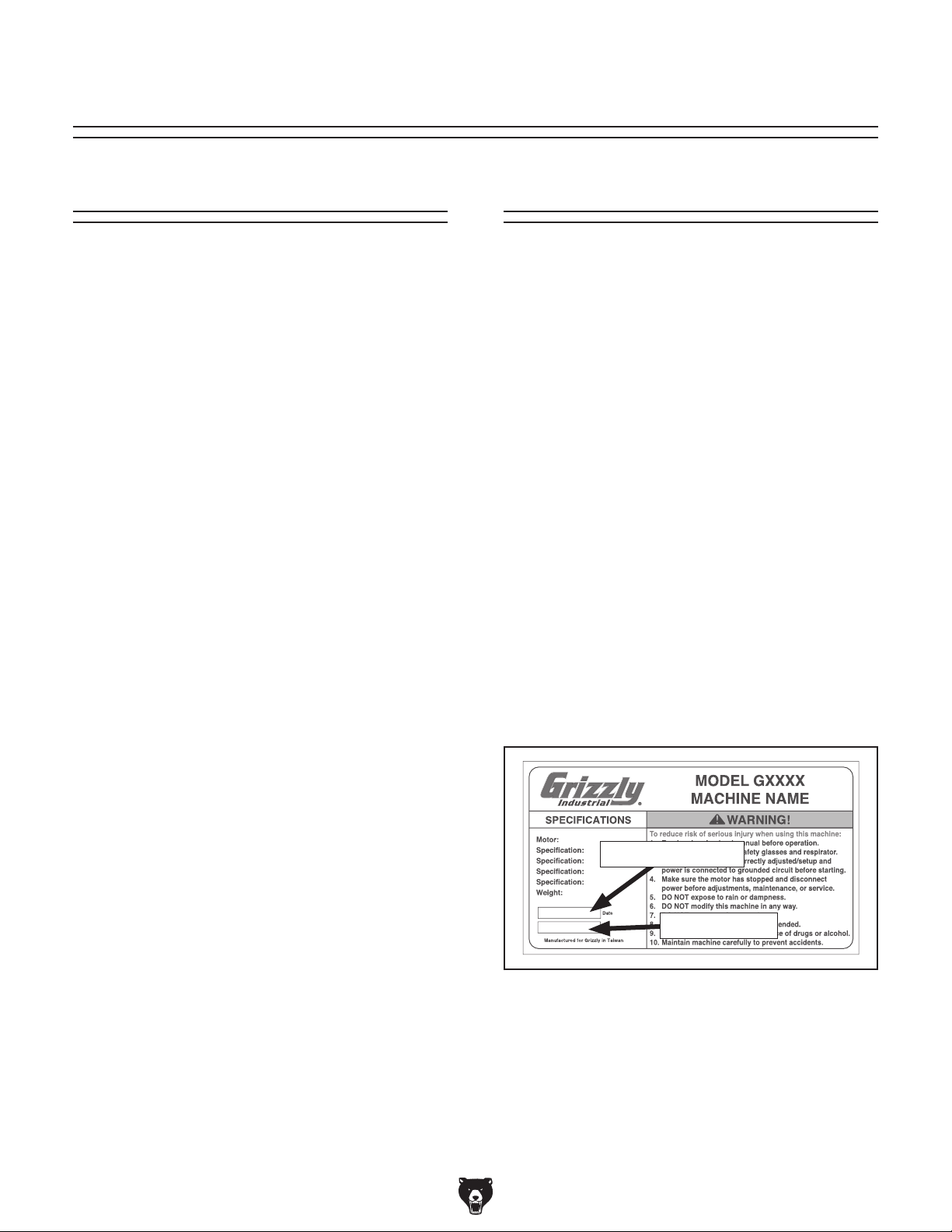
for help. Before calling, make sure you write down
the
from
the machine ID label (see below). This information
is required for us to provide proper tech support,
and it helps us determine if updated documentation is available for your machine.
We stand behind our machines! If you have questions or need help, contact us with the information
below. Before contacting, make sure you get the
serial number
machine ID label. This will help us help you faster.
We want your feedback on this manual. What did
you like about it? Where could it be improved?
Please take a few minutes to give us feedback.
Email: manuals@grizzly.com
Contact Info
and manufacture date from the
Grizzly Technical Support
1815 W. Battlefield
Springfield, MO 65807
Phone: (570) 546-9663
Email: techsupport@grizzly.com
Grizzly Documentation Manager
P.O. Box 2069
Bellingham, WA 98227-2069
Manual Accuracy
made every effort to be exact with the
sometimes the machine
.
,
e post
manual updates for free
www.grizzly.com.
Manufacture Date and Serial Number
Manufacture Date
Serial Number
-2-
Model G0823 (Mfd. Since 2/17)
Page 5
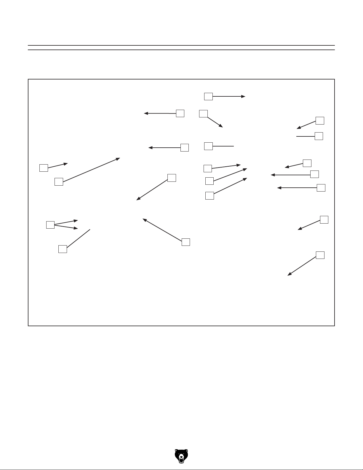
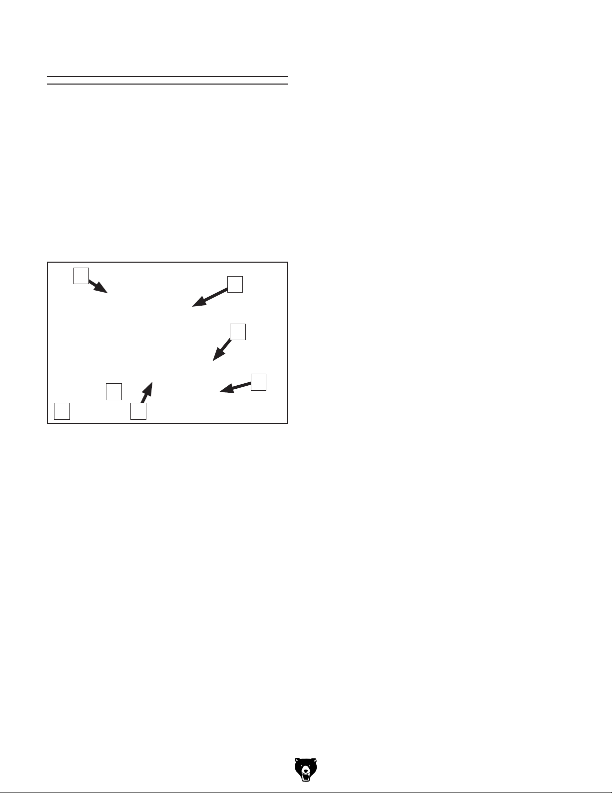
Identification
Become familiar with the names and locations of the controls and features shown below to better understand
the instructions in this manual.
N
E
F
D
C
B
A
G
M
O
P
L
Q
K
R
J
S
I
T
H
U
A. Table Tilt Clamp
B. Table Lock Handles
C. Quill Lock Handle
D. Headstock Elevation Crank
E. Belt Cover
F. Fine Downfeed Handwheel
G. Table
H. Pivot Lock Handle
I. Chuck
J. Spindle
K. Depth Stop Adjustment Knob
Model G0823 (Mfd. Since 2/17)
L. Depth Stop Scale
M. Control Panel
N. Drawbar Cap
O. Motor
P. Motor Locking Lever
Q. Coarse Downfeed Lever
R. Column
S. Rack
T. Table Elevation Crank
U. Base
-3-
Page 6
Controls &
To reduce your risk of
serious injury, read this
entire manual BEFORE
Components
using machine.
E. Fine Downfeed Handwheel: When rotated,
provides fine vertical control in either direction of spindle travel. Includes graduated
collar marked in 0.001" increments.
J
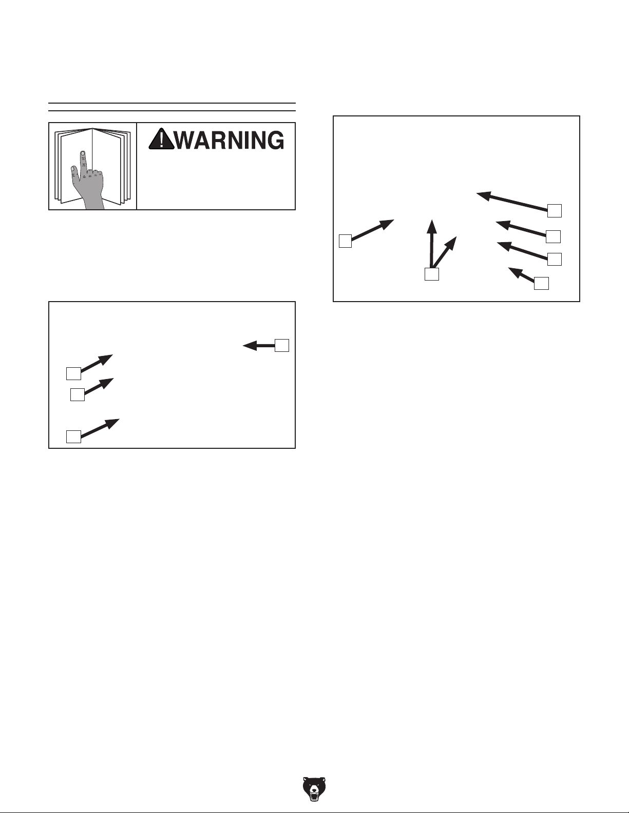
Refer to Figures 1–4 and the following descriptions to become familiar with the basic controls of
this machine.
Headstock
D
A
B
C
Figure 1. Headstock controls (right).
A. Depth Stop: Stops spindle travel at pre-
determined depth.
B. Depth Scale: Indicates drilling depth and
position of depth stop.
C. Depth Stop Adjustment Knob: Positions
depth stop height.
D. Motor Locking Lever: When loosened,
allows adjustment of motor position when
changing spindle speeds. When tightened,
locks motor in position to maintain belt
tension.
E
F
Figure 2. Downfeed controls.
F. Coarse Downfeed Graduated Collars:
Adjust graduated collar for repeatable drilling
operations.
G. Coarse Downfeed Levers: Provide coarse
vertical control over spindle when pulled
down. Automatically returns spindle to starting position when released.
H. Coarse Handle Lock-Down Thumb Screw:
When tightened, secures coarse downfeed
handles for operation. When loosened, allows
coarse downfeed handles to pull outward,
engaging the auto-downfeed function.
I. Depth Graduated Dial Collar Lock: Secures
graduated dial for precise, repeatable drilling
operations.
J. Auto Downfeed Rate Selector Knob:
Selects speed of quill's vertical movement in
increments of 0.004", 0.008", and 0.012" per
rotation.
I
H
G
-4-
Model G0823 (Mfd. Since 2/17)
Page 7
K. Headstock Elevation Crank: Raises and
lowers headstock along column.
L. Quill Lock: Locks quill in position. Ty pi cal ly
used in tandem with fine downfeed handwheel.
K
Control Panel
P
Q
R
S
T
L
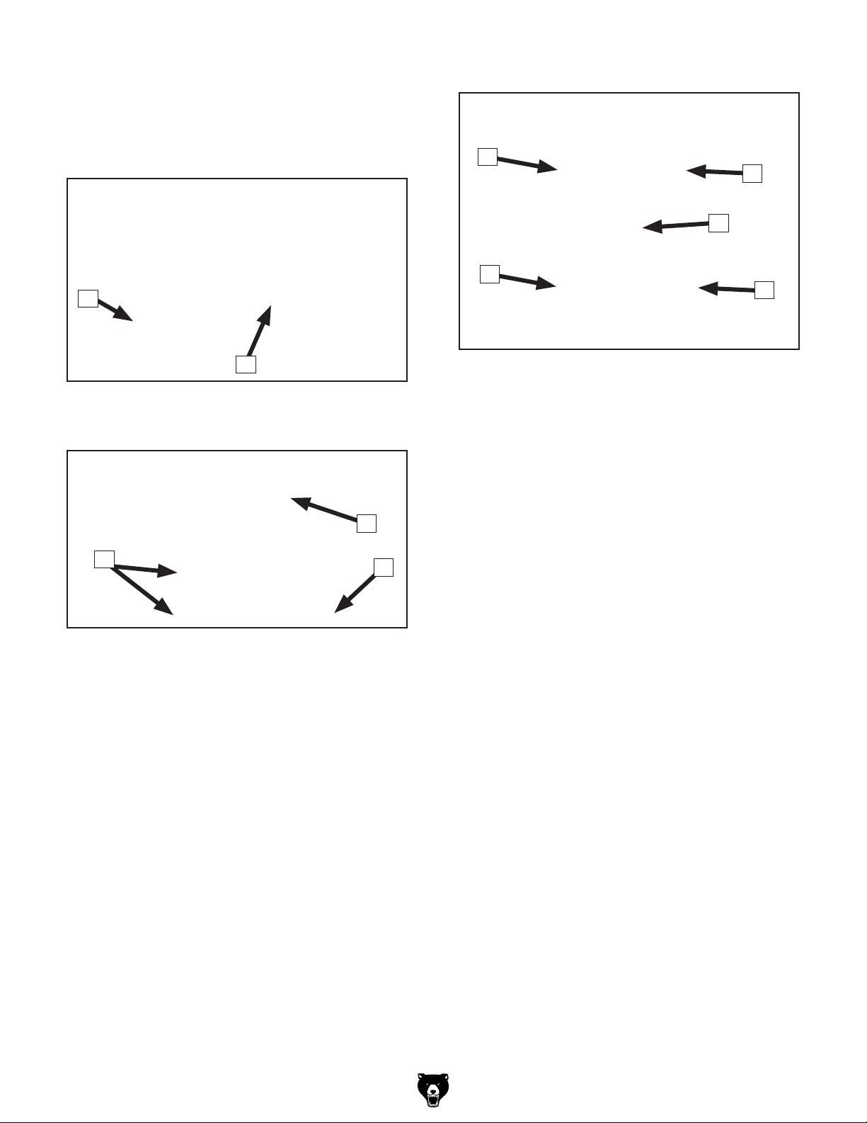
Figure 3. Headstock controls (left).
Table
N
M
Figure 4. Table controls (from below).
M. Table Lock Handles: Secure table assem-
bly in place along column. Loosen to raise
or lower table, or to rotate table assembly
around column.
N Pivot Lock Handle: Allows table to rotate
freely when loosened.
O
Figure 5. Control panel.
P. FORWARD Button: Rotates spindle in clock-
wise direction. Begins downward auto-feed
function when auto-feed is engaged.
Q. REVERSE Button: Rotates spindle in coun-
terclockwise direction. Begins upward autofeed function when auto-feed is engaged.
R. POWER Indicator Light: Illuminates when
machine is connected to power.
S. STOP Button: Stops motor function.
T. E-STOP Button: Immediately cuts power to
motor and control panel when pressed. Twist
button clockwise to reset.
O. Table Elevation Crank: Changes elevation
of table assembly.
Model G0823 (Mfd. Since 2/17)
-5-
Page 8

Machine Data Sheet
MACHINE DATA
SHEET
Customer Service #: (570) 546-9663 · To Order Call: (800) 523-4777 · Fax #: (800) 438-5901
MODEL G0823 DRILL PRESS WITH AUTO DOWNFEED
Product Dimensions:
Weight.............................................................................................................................................................. 662 lbs.
Width (side-to-side) x Depth (front-to-back) x Height..................................................................... 23 x 35-1/2 x 67 in.
Footprint (Length x Width)............................................................................................................................ 26 x 18 in.
Shipping Dimensions:
Type.......................................................................................................................................................... Wood Crate
Content........................................................................................................................................................... Machine
Weight.............................................................................................................................................................. 772 lbs.
Length x Width x Height....................................................................................................................... 34 x 30 x 73 in.
Must Ship Upright................................................................................................................................................... Yes
Electrical:
Power Requirement........................................................................................................... 220V, Single-Phase, 60 Hz
Full-Load Current Rating....................................................................................................................................... 8.6A
Minimum Circuit Size.............................................................................................................................................. 15A
Connection Type....................................................................................................................................... Cord & Plug
Power Cord Included.............................................................................................................................................. Yes
Power Cord Length.......................................................................................................................................... 6-1/2 ft.
Power Cord Gauge......................................................................................................................................... 14 AWG
Plug Included........................................................................................................................................................... No
Recommended Plug Type..................................................................................................................................... 6-15
Switch Type........................................................................................................................... Forward/Reverse Switch
Motors:
Main
Type................................................................................................................. TEFC Capacitor-Start Induction
Horsepower................................................................................................................................................ 2 HP
Phase............................................................................................................................................ Single-Phase
Amps........................................................................................................................................................... 8.6A
Speed................................................................................................................................................ 1720 RPM
Power Transfer ............................................................................................................................... V-Belt Drive
Bearings..................................................................................................... Shielded & Permanently Lubricated
Main Specifications:
Operation Information
Type........................................................................................................................................................... Floor
Swing......................................................................................................................................................... 15 in.
Spindle Taper............................................................................................................................................... R-8
Spindle Travel........................................................................................................................................ 5-1/8 in.
Max. Distance From Spindle to Column................................................................................................ 7-1/2 in.
Max. Distance From Spindle to Table................................................................................................. 28-1/4 in.
Number of Spindle Speeds............................................................................................................................. 12
Range of Spindle Speeds........................................................................................................ 140 – 2436 RPM
Drilling Capacity (Mild Steel)................................................................................................................. 1-1/8 in.
Drill Chuck Type........................................................................................................................................... B16
Drill Chuck Size............................................................................................................................. 1/64 – 1/2 in.
-6-
Model G0823 (Mfd. Since 2/17)
Page 9

Spindle Information
Distance From Spindle to Base........................................................................................................... 45-1/4 in.
Quill Diameter............................................................................................................................ 75mm (2.95 in.)
Table Information
Max. Table Tilt (Left/Right)..................................................................................................................... 60 deg.
Table Swivel Around Center................................................................................................................. 360 deg.
Table Swivel Around Column............................................................................................................... 360 deg.
Max. Movement of Work Table............................................................................................................ 23-1/2 in.
Table Length.............................................................................................................................................. 15 in.
Table Width................................................................................................................................................ 14 in.
Table Thickness.................................................................................................................................... 1-5/8 in.
Vertical Table Travel.................................................................................................... Crank Handle Operation
Number of T-Slots............................................................................................................................................ 2
T-Slot Size................................................................................................................................................ 1/2 in.
T-
Floor-To-Table Height........................................................................................................... 18-1/2 – 41-3/4 in.
Construction
Table.................................................................................................................................................... Cast Iron
Column................................................................................................................................................. Cast Iron
Spindle Housing................................................................................................................................... Cast Iron
Head.................................................................................................................................................... Cast Iron
Base..................................................................................................................................................... Cast Iron
Paint Type/Finish.................................................................................................................................... Enamel
Other Related Information
Base Length........................................................................................................................................ 25-1/2 in.
Base Width.......................................................................................................................................... 17-1/2 in.
Column Diameter................................................................................................................................... 4-1/2 in.
Slot Centers..................................................................................................................................... 6-5/16 in.
Other Specifications:
Country of Origin ................................................................................................................................................ China
Warranty ........................................................................................................................................................... 1 Year
Serial Number Location .................................................................................................................................. ID Label
ISO 9001 Factory .................................................................................................................................................. Yes
Certified by a Nationally Recognized Testing Laboratory (NRTL) .......................................................................... No
Features:
Solid Cast-Iron Construction
12 Speeds
Two T-Slots Accommodate 1/2" Clamping Kit
2 HP Motor
R-8 Spindle
Power Downfeed
Model G0823 (Mfd. Since 2/17)
-7-
Page 10

SECTION 1: SAFETY
For Your Own Safety, Read Instruction
Manual Before Operating This Machine
The purpose of safety symbols is to attract your attention to possible hazardous conditions.
This manual uses a series of symbols and signal words intended to convey the level of importance of the safety messages. The progression of symbols is described below. Remember that
safety messages by themselves do not eliminate danger and are not a substitute for proper
accident prevention measures. Always use common sense and good judgment.
Indicates an imminently hazardous situation which, if not avoided,
WILL result in death or serious injury.
Indicates a potentially hazardous situation which, if not avoided,
COULD result in death or serious injury.
Indicates a potentially hazardous situation which, if not avoided,
MAY result in minor or moderate injury. It may also be used to alert
against unsafe practices.
This symbol is used to alert the user to useful information about
NOTICE
proper operation of the machine.
Safety Instructions for Machinery
OWNER’S MANUAL. Read and understand this
owner’s manual BEFORE using machine.
TRAINED OPERATORS ONLY. Untrained operators have a higher risk of being hurt or killed.
Only allow trained/supervised people to use this
machine. When machine is not being used, disconnect power, remove switch keys, or lock-out
machine to prevent unauthorized use—especially
around children. Make your workshop kid proof!
DANGEROUS ENVIRONMENTS. Do not use
machinery in areas that are wet, cluttered, or have
poor lighting. Operating machinery in these areas
greatly increases the risk of accidents and injury.
MENTAL ALERTNESS REQUIRED. Full mental
alertness is required for safe operation of machinery. Never operate under the influence of drugs or
alcohol, when tired, or when distracted.
ELECTRICAL EQUIPMENT INJURY RISKS. You
can be shocked, burned, or killed by touching live
electrical components or improperly grounded
machinery. To reduce this risk, only allow qualified
service personnel to do electrical installation or
repair work, and always disconnect power before
accessing or exposing electrical equipment.
DISCONNECT POWER FIRST.
nect machine from power supply BEFORE making
adjustments, changing tooling, or servicing machine.
This prevents an injury risk from unintended startup
or contact with live electrical components.
EYE PROTECTION. Always wear ANSI-approved
safety glasses or a face shield when operating or
observing machinery to reduce the risk of eye
injury or blindness from flying particles. Everyday
eyeglasses are NOT approved safety glasses.
Always discon-
-8-
Model G0823 (Mfd. Since 2/17)
Page 11

WEARING PROPER APPAREL. Do not wear
clothing, apparel or jewelry that can become
entangled in moving parts. Always tie back or
cover long hair. Wear non-slip footwear to reduce
risk of slipping and losing control or accidentally
contacting cutting tool or moving parts.
HAZARDOUS DUST. Dust created by machinery
operations may cause cancer, birth defects, or
long-term respiratory damage. Be aware of dust
hazards associated with each workpiece material. Always wear a NIOSH-approved respirator to
reduce your risk.
HEARING PROTECTION. Always wear hearing protection when operating or observing loud
machinery. Extended exposure to this noise
without hearing protection can cause permanent
hearing loss.
REMOVE ADJUSTING TOOLS. Tools left on
machinery can become dangerous projectiles
upon startup. Never leave chuck keys, wrenches,
or any other tools on machine. Always verify
removal before starting!
USE CORRECT TOOL FOR THE JOB. Only use
this tool for its intended purpose—do not force
it or an attachment to do a job for which it was
not designed. Never make unapproved modifications—modifying tool or using it differently than
intended may result in malfunction or mechanical
failure that can lead to personal injury or death!
AWKWARD POSITIONS. Keep proper footing
and balance at all times when operating machine.
Do not overreach! Avoid awkward hand positions
that make workpiece control difficult or increase
the risk of accidental injury.
CHILDREN & BYSTANDERS. Keep children and
bystanders at a safe distance from the work area.
Stop using machine if they become a distraction.
GUARDS & COVERS. Guards and covers reduce
accidental contact with moving parts or flying
debris. Make sure they are properly installed,
undamaged, and working correctly BEFORE
operating machine.
FORCING MACHINERY. Do not force machine.
It will do the job safer and better at the rate for
which it was designed.
NEVER STAND ON MACHINE. Serious injury
may occur if machine is tipped or if the cutting
tool is unintentionally contacted.
STABLE MACHINE. Unexpected movement during operation greatly increases risk of injury or
loss of control. Before starting, verify machine is
stable and mobile base (if used) is locked.
USE RECOMMENDED ACCESSORIES. Consult
this owner’s manual or the manufacturer for recommended accessories. Using improper accessories will increase the risk of serious injury.
UNATTENDED OPERATION. To reduce the
risk of accidental injury, turn machine OFF and
ensure all moving parts completely stop before
walking away. Never leave machine running
while unattended.
MAINTAIN WITH CARE. Follow all maintenance
instructions and lubrication schedules to keep
machine in good working condition. A machine
that is improperly maintained could malfunction,
leading to serious personal injury or death.
DAMAGED PARTS. Regularly inspect machine
for damaged, loose, or mis-adjusted parts—or
any condition that could affect safe operation.
Immediately repair/replace BEFORE operating
machine. For your own safety, DO NOT operate
machine with damaged parts!
MAINTAIN POWER CORDS. When disconnecting cord-connected machines from power, grab
and pull the plug—NOT the cord. Pulling the cord
may damage the wires inside. Do not handle
cord/plug with wet hands. Avoid cord damage by
keeping it away from heated surfaces, high traffic
areas, harsh chemicals, and wet/damp locations.
EXPERIENCING DIFFICULTIES. If at any time
you experience difficulties performing the intended operation, stop using the machine! Contact our
Technical Support at (570) 546-9663.
Model G0823 (Mfd. Since 2/17)
-9-
Page 12

Additional Safety for Drill Presses
Serious injury or death can occur from getting clothing, jewelry, or long hair entangled in
rotating spindle or bit/cutting tool. Contact with rotating bit/cutting tool can result in severe cuts
or amputation of fingers. Flying metal chips can cause blindness or eye injuries. Broken bits/
cutting tools, unsecured workpieces, chuck keys, or other adjustment tools thrown from rotating
spindle can strike nearby operator or bystanders with deadly force. To reduce the risk of these
hazards, operator and bystanders MUST completely heed hazards and warnings below.
WEARING PROPER PPE. Flying chips created by
drilling can cause eye injuries or blindness. Always
wear a face shield in addition to safety glasses.
Always keep hands and fingers away from drill bit/
cutting tool. Avoid awkward hand positions, where
a sudden slip could cause hand to move into bit/
cutting tool.
AVOIDING ENTANGLEMENT. DO NOT wear
loose clothing, gloves, or jewelry, and tie back long
hair. Keep all guards in place and secure. Always
allow spindle to stop on its own. DO NOT stop
spindle using your hand or any other object.
REMOVING ADJUSTMENT TOOLS. Chuck key,
drawbar wrench, and other tools left on machine
can become deadly projectiles when spindle is
started. Remove all loose items or tools used on
spindle immediately after use.
SECURING BIT/CUTTING TOOL. Firmly secure
bit/cutting tool so it does not fly out of spindle during operation or startup.
SECURING TABLE AND HEADSTOCK. To avoid
accidental contact with tool/bit, tighten all table
and headstock locks before operating drill.
CORRECT SPINDLE SPEED. Using wrong spindle speed can cause bits/cutting tools to break
and strike operator or bystanders. Follow recommended speeds and feeds for each size/type of
bit/cutting tool and workpiece material.
WORKPIECE PREPARATION. To avoid loss of
workpiece control, DO NOT drill material with an
uneven surface on the table, unless a suitable support is used. To avoid impact injuries, make sure
workpiece is free of nails or foreign objects in area
to be drilled.
WORKPIECE CONTROL. An unsecured workpiece may unexpectedly shift, spin out of control,
or be thrown if bit/cutting tool “grabs” during operation. Clamp workpiece to table or in table-mounted
vise, or brace against column to prevent rotation.
NEVER hold workpiece by hand during operation.
NEVER start machine with bit/cutting tool touching
workpiece; allow spindle to gain full speed before
drilling.
INSPECTING BIT/CUTTING TOOL. Damaged
bits/cutting tools may break apart during operation
and hit operator or bystanders. Dull bits/cutting
tools increase cutting resistance and are more
likely to grab and spin/throw workpiece. Always
inspect bits/cutting tools for sharpness, chips, or
cracks before each use. Replace dull, chipped, or
cracked bits/cutting tools immediately.
MAINTAINING MACHINE. Keep machine in proper working condition to help ensure that it functions
safely and all guards and other components work
as intended. Perform routine inspections and all
necessary maintenance. Never operate machine
with damaged or worn parts that can break or
result in unexpected movement during operation.
CLEANING MACHINE SAFELY. To avoid contact
with tool/bit, never clear chips while spindle is
turning. To avoid cuts and eye injuries, DO NOT
clear chips by hand or with compressed air—use
a brush or vacuum instead.
DISCONNECT POWER FIRST. To reduce risk of
electrocution or injury from unexpected startup,
make sure drill is turned OFF, disconnected
from power, and all moving parts have come to a
complete stop before changing bits/cutting tools
or starting any inspection, adjustment, or maintenance procedure.
-10 -
Model G0823 (Mfd. Since 2/17)
Page 13

SECTION 2: POWER SUPPLY
Before installing the machine, consider the availability and proximity of the required power supply
circuit. If an existing circuit does not meet the
requirements for this machine, a new circuit must
be installed. To minimize the risk of electrocution,
fire, or equipment damage, installation work and
electrical wiring must be done by an electrician or
qualified service personnel in accordance with all
applicable codes and standards.
or equipment damage
may occur if machine is
not properly grounded
and connected to power
The full-load current rating is the amperage a
machine draws at 100% of the rated output power.
On machines with multiple motors, this is the
amperage drawn by the largest motor or sum of all
motors and electrical devices that might operate
at one time during normal operations.
The full-load current is not the maximum amount
of amps that the machine will draw. If the machine
is overloaded, it will draw additional amps beyond
the full-load rating.
If the machine is overloaded for a sufficient length
of time, damage, overheating, or fire may result—
especially if connected to an undersized circuit.
To reduce the risk of these hazards, avoid overloading the machine during operation and make
sure it is connected to a power supply circuit that
meets the specified circuit requirements.
For your own safety and protection of
Note: Circuit requirements in this manual apply to
a dedicated circuit—where only one machine will
be running on the circuit at a time. If machine will
be connected to a shared circuit where multiple
machines may be running at the same time, consult an electrician or qualified service personnel to
ensure circuit is properly sized for safe operation.
A power supply circuit includes all electrical
equipment between the breaker box or fuse panel
in the building and the machine. The power supply circuit used for this machine must be sized to
safely handle the full-load current drawn from the
machine for an extended period of time. (If this
machine is connected to a circuit protected by
fuses, use a time delay fuse marked D.)
This machine is prewired to operate on a power
supply circuit that has a verified ground and meets
the following requirements:
Availability
Electrocution, fire, shock,
supply.
Full-Load Current Rating
Circuit Information
property, consult an electrician if you are
unsure about wiring practices or electrical
codes in your area.
Full-Load Current Rating at 220V .... 8.6 Amps
Model G0823 (Mfd. Since 2/17)
Circuit Requirements
Nominal Voltage .........20 8V, 2 20V, 2 30V, 2 40V
Cycle .......................................................... 60 Hz
Phase ........................................... Single-Phase
Power Supply Circuit ......................... 15 Amps
Plug/Receptacle ............................. NEMA 6-15
-11-
Page 14

Improper connection of the equipment-grounding
wire can result in a risk of electric shock. The
wire with green insulation (with or without yellow
stripes) is the equipment-grounding wire. If repair
or replacement of the power cord or plug is necessary, do not connect the equipment-grounding
wire to a live (current carrying) terminal.
Check with a qualified electrician or service personnel if you do not understand these grounding
requirements, or if you are in doubt about whether
the tool is properly grounded. If you ever notice
that a cord or plug is damaged or worn, disconnect it from power, and immediately replace it with
a new one.
We do not recommend using an extension cord
with this machine.
cord, only use it if absolutely necessary and only
on a temporary basis.
Extension cords cause voltage drop, which can
damage electrical components and shorten motor
life. Voltage drop increases as the extension cord
size gets longer and the gauge size gets smaller
(higher gauge numbers indicate smaller sizes).
Any extension cord used with this machine must
be in good condition and contain a ground wire
and matching plug/receptacle. Additionally, it must
meet the following size requirements:
Grounding Requirements
This machine MUST be grounded. In the event
of certain malfunctions or breakdowns, grounding
reduces the risk of electric shock by providing a
path of least resistance for electric current.
This machine is equipped with a power cord that
has an equipment-grounding wire and a grounding
plug. Only insert plug into a matching receptacle
(outlet) that is properly installed and grounded in
accordance with all local codes and ordinances.
DO NOT modify the provided plug!
No adapter should be used with plug. If
process. DO NOT connect to power until
GROUNDED
6-15 RECEPTACLE
Current Carrying Prongs
6-15 PLUG
Serious injury could occur if you connect
machine to power before completing setup
instructed later in this manual.
Grounding Prong
Figure 6. Typical 6-15 plug and receptacle.
plug does not fit available receptacle, or if
machine must be reconnected for use on a
different type of circuit, reconnection must
be performed by an electrician or qualified
service personnel, and it must comply with
all local codes and ordinances.
-12-
Extension Cords
If you must use an extension
Minimum Gauge Size ...........................14 AWG
Maximum Length (Shorter is Better).......50 ft.
Model G0823 (Mfd. Since 2/17)
Page 15

SECTION 3: SETUP
This machine was carefully packaged for safe
transport. When unpacking, separate all enclosed
items from packaging materials and inspect them
for shipping damage.
,
please
IMPORTANT:
you are completely satisfied with the machine and
have resolved any issues between Grizzly or the
shipping agent. You MUST have the original pack-
aging to file a freight claim. It is also extremely
helpful if you need to return your machine later.
Keep children and pets away
from plastic bags or packing
materials shipped with this
The following is a list of items shipped with your
machine. Before beginning setup, lay these items
out and inventory them.
If any non-proprietary parts are missing (e.g. a
nut or a washer), we will gladly replace them; or
for the sake of expediency, replacements can be
obtained at your local hardware store.
Unpacking
If items are damaged
call us immediately at (570) 546-9663.
Save all packaging materials until
SUFFOCATION HAZARD!
machine. Discard immediately.
Needed for Setup
Inventory
Box 1 (Figure 7) Qty
A. Toolbox ....................................................... 1
B. Bottle for Oil ............................................... 1
C. Lug Wrench 20/25mm ................................ 1
D. Open-End Wrench 17/19mm ...................... 1
E. Hex Wrenches 3, 4, 5mm ........................... 3
F. T-bolts M14-2 x 55 ...................................... 2
—Hex Nuts M14-2 ...................................... 2
—Flat Washers 14mm ................................ 2
G. Drift Key ...................................................... 1
H. Spindle Sleeve MT#3–MT#2 ...................... 1
I. Spindle Sleeve R-8–MT#3 ......................... 1
J. Drill Chuck Arbor R8-B16 ........................... 1
K. Drill Chuck B16 1–13mm ............................ 1
L. Chuck Key .................................................. 1
The following are needed to complete the setup
process, but are not included with your machine.
Description Qty
• Additional People ....................................... 1
• Safety Glasses ........................................... 1
• Cleaner/Degreaser (Page 14) .... As Needed
• Disposable Shop Rags ............... As Needed
• Forklift ......................................................... 1
• Lifting Sling (Rated 1000 lbs. Minimum)..... 2
If you cannot find an item on this list, carefully check around/inside the machine and
packaging materials. Often, these items get
lost in packaging materials while unpacking or they are pre-installed at the factory.
Model G0823 (Mfd. Since 2/17)
NOTICE
A
J
K
L
Figure 7. Toolbox inventory.
I
B
C
D
E
H
G
F
-13-
Page 16

The unpainted surfaces of your machine are
coated with a heavy-duty rust preventative that
prevents corrosion during shipment and storage.
This rust preventative works extremely well, but it
will take a little time to clean.
Be patient and do a thorough job cleaning your
machine. The time you spend doing this now will
give you a better appreciation for the proper care
of your machine's unpainted surfaces.
There are many ways to remove this rust preventative, but the following steps work well in a wide
variety of situations. Always follow the manufacturer’s instructions with any cleaning product you
use and make sure you work in a well-ventilated
area to minimize exposure to toxic fumes.
Before cleaning, gather the following:
• Disposable rags
• Cleaner/degreaser (WD•40 works well)
• Safety glasses & disposable gloves
• Plastic paint scraper (optional)
Basic steps for removing rust preventative:
1.
2.
3.
4.
Many cleaning solvents
work in a well-ventilated
Avoid chlorine-based solvents, such as
Cleanup
Gasoline and petroleum
products have low flash
points and can explode
or cause fire if used to
clean machinery. Av oi d
using these products
to clean machinery.
Put on safety glasses.
Coat the rust preventative with a liberal
amount of cleaner/degreaser, then let it soak
for 5–10 minutes.
Wipe off the surfaces. If your cleaner/degreas-
er is effective, the rust preventative will wipe
off easily. If you have a plastic paint scraper,
scrape off as much as you can first, then wipe
off the rest with the rag.
are toxic if inhaled. Only
area.
NOTICE
acetone or brake parts cleaner, that may
damage painted surfaces.
T23692—Orange Power Degreaser
A great product for removing the waxy shipping
grease from your machine during clean up.
Figure 8. T23692 Orange Power Degreaser.
Repeat Steps 2–3 as necessary until clean,
then coat all unpainted surfaces with a quality
metal protectant to prevent rust.
-14-
Model G0823 (Mfd. Since 2/17)
Page 17
Site Considerations
Weight Load
Refer to the
of your machine. Make sure that the surface upon
which the machine is placed will bear the weight
of the machine, additional equipment that may be
installed on the machine, and the heaviest workpiece that will be used. Additionally, consider the
weight of the operator and any dynamic loading
that may occur when operating the machine.
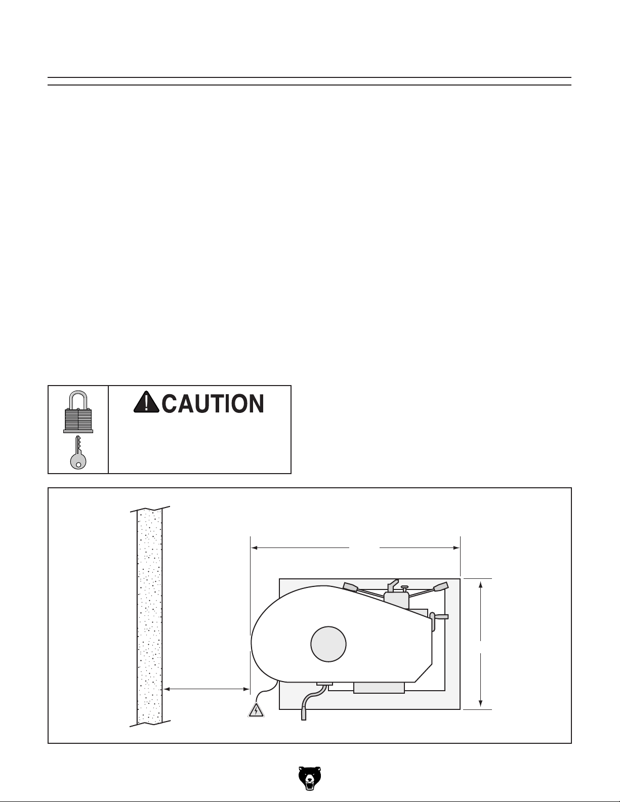
Space Allocation
Consider the largest size of workpiece that will
be processed through this machine and provide
enough space around the machine for adequate
operator material handling or the installation of
auxiliary equipment. With permanent installations,
leave enough space around the machine to open
or remove doors/covers as required by the maintenance and service described in this manual.
See below for required space allocation.
Physical Environment
Extreme conditions for this type of machinery are
Place this machine near an existing power source.
other hazards. Make sure to leave enough space
Shadows, glare, or strobe effects that may distract
or impede the operator must be eliminated.
Machine Data Sheet for the weight
Children or untrained people
may be seriously injured by
this machine. Only install in an
access restricted location.
The physical environment where the machine is
operated is important for safe operation and longevity of machine components. For best results,
operate this machine in a dry environment that is
free from excessive moisture, hazardous chemicals, airborne abrasives, or extreme conditions.
generally those where the ambient temperature
range exceeds 41°–104°F; the relative humidity
range exceeds 20%–95% (non-condensing); or
the environment is subject to vibration, shocks,
or bumps.
Electrical Installation
Make sure all power cords are protected from
traffic, material handling, moisture, chemicals, or
around machine to disconnect power supply or
apply a lockout/tagout device, if required.
Lighting
Lighting around the machine must be adequate
enough that operations can be performed safely.
351⁄2 "
Model G0823 (Mfd. Since 2/17)
30" Minimum
for Maintenance
Figure 9. Minimum working clearances.
23"
-15-
Page 18
Lifting & Placing
get help from other people
Anchoring machinery to the floor prevents tipping
or shifting and reduces vibration that may occur
during operation, resulting in a machine that runs
slightly quieter and feels more solid.
If the machine will be installed in a commercial or
workplace setting, or if it is permanently connected (hardwired) to the power supply, local codes
may require that it be anchored to the floor.
If not required by any local codes, fastening the
machine to the floor is an optional step. If you
choose not to do this with your machine, we recommend placing it on machine mounts, as these
provide an easy method for leveling and they have
vibration-absorbing pads.
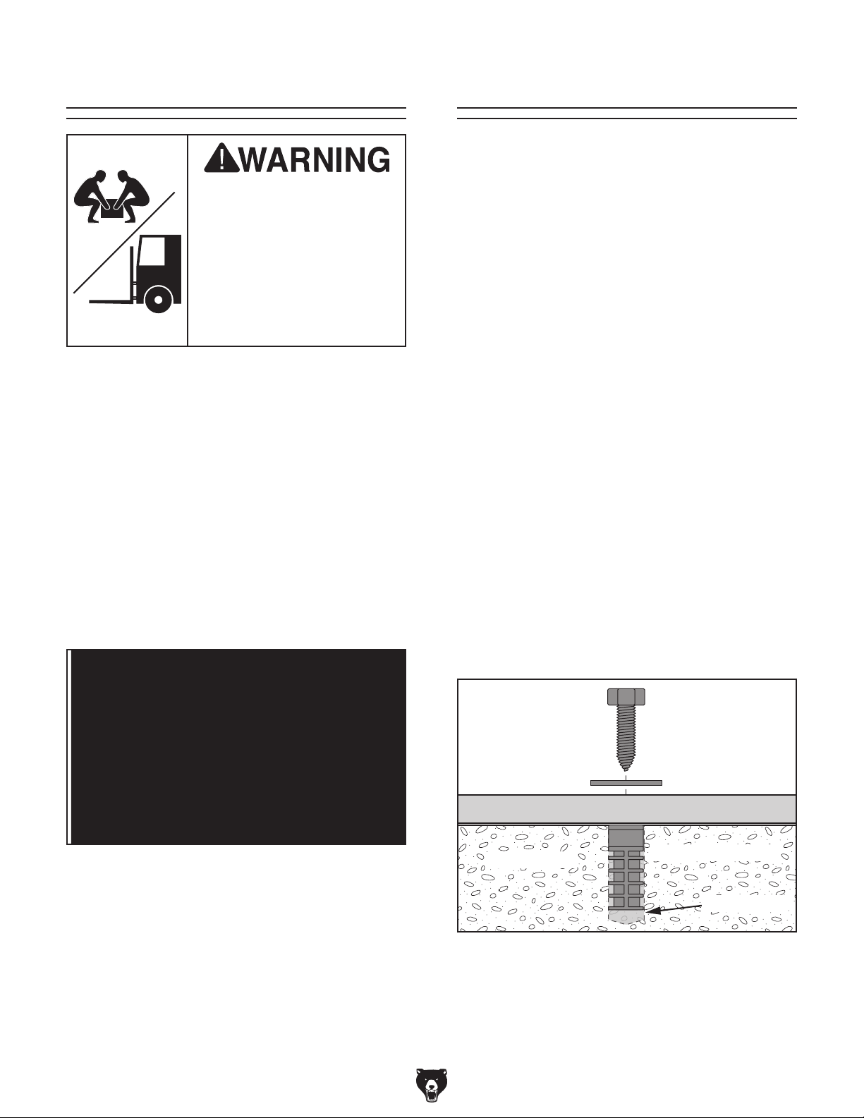
Lag shield anchors with lag screws (see below)
are a popular way to anchor machinery to a concrete floor, because the anchors sit flush with the
floor surface, making it easy to unbolt and move
the machine later, if needed. However, anytime
local codes apply, you MUST follow the anchoring
methodology specified by the code.
Anchoring to Floor
HEAVY LIF T!
Straining or crushing injury
may occur from improperly
lifting machine or some of
its parts. To reduce this risk,
and use a forklift (or other
lifting equipment) rated for
weight of this machine.
To move and place drill:
1. Place shipping crate near final machine
mounting location.
2. Remove top portion of crate from the shipping
pallet, place lifting slings around headstock
(see Figure 10), and attach them securely to
forklift (or other power lifting equipment).
Number of Mounting Holes ............................ 4
Diameter of Mounting Hardware .................
5
⁄8"
Anchoring to Concrete Floors
Note: Be sure slings are far enough apart to
avoid putting pressure on belt cover; otherwise, it can become damaged from the force
of the slings while lifting.
Figure 10. Lifting slings properly wrapped
around headstock and positioned to avoid
damage to belt cover while lifting.
3. Unbolt machine from pallet.
4. With another person to help to steady
machine, lift it just enough to clear pallet and
any floor obstacles, then place machine in its
final position on shop floor.
-16 -
Lag Screw
Flat Washer
Machine Base
Concrete
Figure 11. Popular method for anchoring
machinery to a concrete floor.
Model G0823 (Mfd. Since 2/17)
Lag Shield Anchor
Drilled Hole
Page 19

Joining Drill Chuck
An arbor is included for the drill chuck that
comes with this machine. The following procedure
describes how to install the arbor in the chuck.
After the arbor is installed in the drill chuck, it
is very difficult to separate the assembly. If you
would like to use a different chuck in the future,
we recommend obtaining a new arbor.
Important: DO NOT install the drill chuck
and arbor assembly into the spindle until AFTER
the test run.
To join drill chuck and arbor:
1.
clean drill
2.
3.
4.
5. Attempt to separate drill chuck and arbor by
hand —if they separate, repeat Steps 3–4.
DO NOT start machine until all preceding
setup instructions have been performed.
Operating an improperly set up machine
Serious injury or death can result from
Once assembly is complete, test run the machine
to ensure it is properly connected to power and
safety components are functioning correctly.
If you find an unusual problem during the test run,
immediately stop the machine, disconnect it from
power, and fix the problem BEFORE operating the
machine again. The
table in the
SERVICE section of this manual can help.
& Arbor
Test Run
Troubleshooting
Use acetone or lacquer thinner to
chuck and arbor mating surfaces, especially
the bore.
Retract chuck jaws completely into chuck.
Insert small end of arbor into chuck.
Hold assembly by the arbor and tap chuck
onto a block of wood with medium force, as
illustrated below.
using this machine BEFORE understanding
its controls and related safety information.
DO NOT operate, or allow others to operate,
machine until the information is understood.
may result in malfunction or unexpected results that can lead to serious injury,
death, or machine/property damage.
Figure 12. Joining drill chuck and arbor.
Model G0823 (Mfd. Since 2/17)
-17-
Page 20
The Test Run consists of verifying the following:
1) The motor powers up and runs correctly, and 2)
the emergency stop button works correctly.
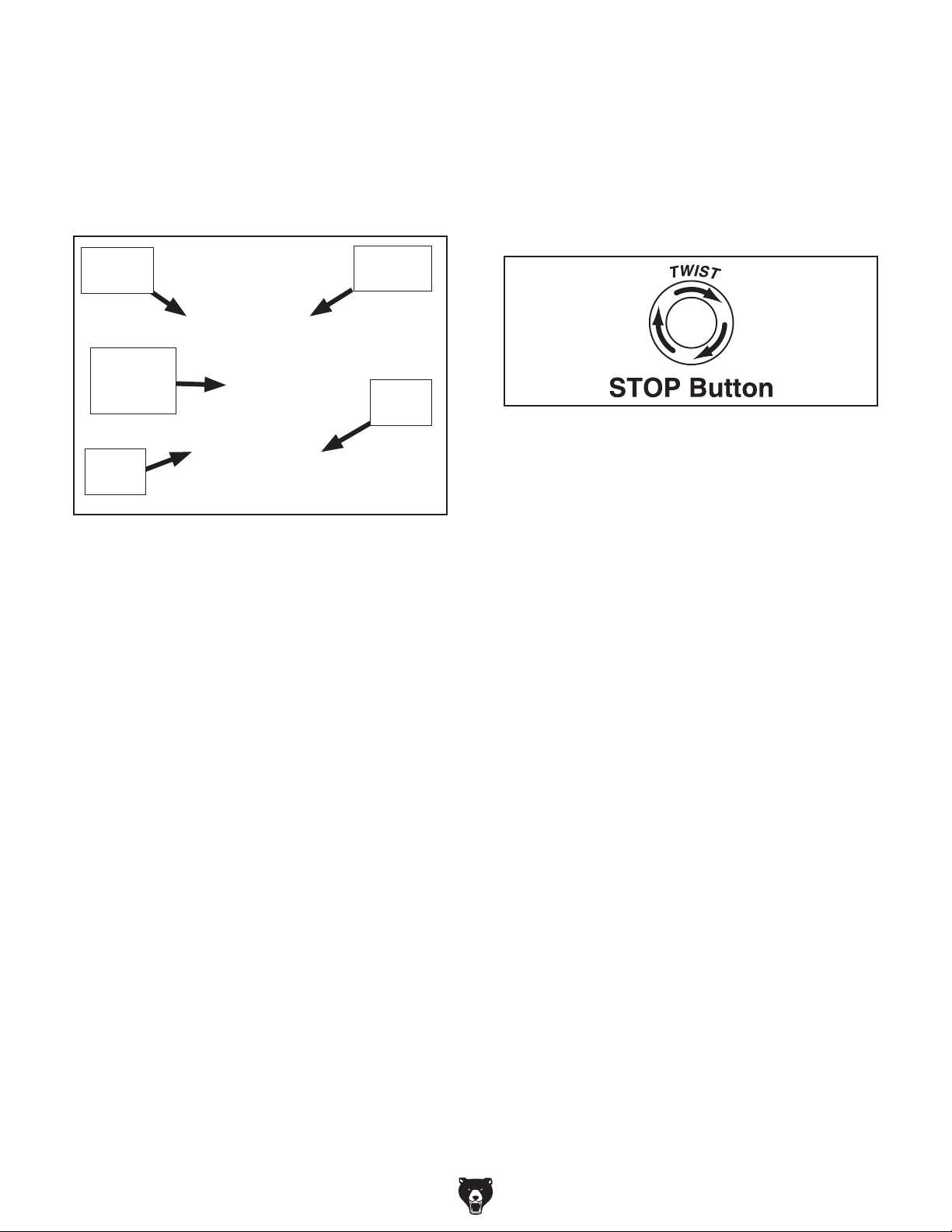
Refer to Figures 13–14 for the locations of the
various controls necessary for performing the
Test Run.
7. Press STOP button to turn spindle OFF.
Allow spindle to come to a complete stop.
8. Press FORWARD button on control panel to
turn machine ON.
9. Press Emergency Stop button to turn machine
OFF.
Forward
Button
Power
Indicator
Light
Stop
Button
Figure 13. Location of controls necessary for
Test Run.
To test run machine:
1. Clear all setup tools away from machine.
2. Connect machine to power supply.
3. Rotate E-STOP button clockwise. Button
should pop outward and power indicator light
should illuminate.
Reverse
Button
E-Stop
Button
Figure 14. Resetting the switch.
10. WITHOUT resetting Emergency Stop but-
ton, try to start machine by pressing the
FORWARD button. The machine should not
start.
— If the machine does not start, the safety
feature of the Emergency Stop button is
working correctly. Congratulations! The
Test Run is complete.
— If the machine does start, immediately
turn it OFF and disconnect power. The
safety feature of the Emergency Stop button is NOT working properly and must be
replaced before further using the machine.
4. Press FORWARD button on control panel
to turn machine ON. The motor should run
smoothly and without unusual problems or
noises.
5. Press STOP button to turn spindle OFF.
Allow spindle to come to a complete stop.
6. Press REVERSE button to turn spindle ON.
The motor should run smoothly and without
unusual problems or noises in the opposite
direction.
-18-
Model G0823 (Mfd. Since 2/17)
Page 21

Spindle Break-In
The spindle break-in procedure distributes lubrication
reduce the risk
of early
if there are any "dry" spots
or areas where lubrication has settled in the bearings. You
efore
placing
for the
first time when the machine is new or if it has
been sitting idle for longer than 6 months.
Always start the spindle break-in at the lowest
speed to minimize wear if there
Allow the spindle to run long enough to warm up
and distribute the bearing grease, then incrementally increase spindle speeds and repeat this process at each speed until reaching the maximum
spindle speed. Following the break-in procedure
in this progressive manner helps minimize any
potential wear that could occur before lubrication
is fully distributed.
To perform spindle break-in:
1. Make sure machine has been properly lubri-
cated. Refer to Lubrication on Page 31.
throughout the bearings to
bearing failure
must complete this procedure b
operational loads on the spindle
are dry spots.
Complete the spindle bearing break-in procedure to prevent rapid wear and tear of
spindle components once the drill press is
placed into operation.
2. Make sure spindle area is free of obstructions.
3. Configure V-belts for a spindle speed of
140 RPM. Refer to Changing Spindle Speed
on Page 22.
4. Connect machine to power and run spindle
in forward direction for 10 minutes. Repeat in
reverse direction.
5. Turn machine OFF, allow spindle to come
to a complete stop, then DISCONNECT
MACHINE FROM POWER!
6. Run spindle for 5 minutes in each direction at
each speed listed below (refer to Changing
Spindle Speed on Page 22) and in progressive order.
a. 413 RPM
b. 819 RPM
c. 1450 RPM
d. 2436 RPM
7. Turn machine OFF.
DO NOT perform this procedure independently of the Test Run section. The drill
press could be seriously damaged if the
controls are set differently than instructed
in that section.
Model G0823 (Mfd. Since 2/17)
Congratulations! Spindle break-in is now complete.
-19 -
Page 22

SECTION 4: OPERATIONS
To reduce your risk of
serious injury, read this
entire manual BEFORE
Keep hair, clothing, and
ing parts at all times.
Entanglement can result
in death, amputation, or
The purpose of this overview is to provide the novice machine operator with a basic understanding
of how the machine is used during operation, so
the
discussed later
in this manual
Due to the generic nature of this overview, it is
not
more about specific operations,
manual,
training from experienced
machine operators
outside of this manual by reading "how-to" books,
trade magazines, or websites.
using machine.
To reduce risk of eye or face injury from
flying chips, always wear approved safety
glasses and a face shield when operating
this machine.
Operation Overview
machine controls/components
are easier to understand.
intended to be an instructional guide. To learn
read this entire
seek additional
, and do additional research
To complete a typical operation, the operator
does the following:
jewelry away from mov-
severe crushing injuries!
If you are not experienced with this type
of machine, WE STRONGLY RECOMMEND
that you seek additional training outside of
this manual. Read books/magazines or get
formal training before beginning any projects. Regardless of the content in this section, Grizzly Industrial will not be held liable
for accidents caused by lack of training.
-20-
1. Examines workpiece to make sure it is suitable for drilling.
2. Puts on required safety glasses and face
shield.
3. Firmly secures workpiece to table using a
vise or T-slot clamps.
4. Installs correct cutting tool for operation.
5. Adjusts table to correct height, then locks it in
place.
6. Selects appropriate spindle speed according
to V-belt configuration chart located inside
belt cover.
7. Connects machine to power, and starts spindle rotation in proper direction for cutting tool
installed.
8. Begins drilling.
9. When finished, stops spindle rotation and
disconnects machine from power.
Model G0823 (Mfd. Since 2/17)
Page 23

Calculating Spindle Speed for Drilling
Using the Drill Bit Speed Chart
The chart shown in Figure 15 is intended as
a guide only. Always follow the manufacturer's
speed recommendations if provided with your
drill bits, cutters, or hole saws. Exceeding the
recommended speeds may be dangerous to the
operator.
The speeds shown here are intended to get you
started. The optimum speed will always depend
on various factors, including tool diameter, drilling
pressure, material hardness, material quality, and
desired finish.
Often, when drilling materials other than wood,
some type of lubrication is necessary.
Twist/Brad Point Drill Bits Soft Wood Hard Wood Plastic Brass Aluminum Mild Steel
1/16" – 3/16" 3000 2500 2500 2500 3000 2500
13/64" – 3/8" 2000 1500 2000 1250 2500 1250
25/64" – 5/8" 1500 750 1500 750 1500 600
11/16" – 1" 750 500 1000 400 1000 350
Lubrication Suggestions
Wood ...........................................................None
Plastics ............................................Soapy Water
Brass ...............................Water-Based Lubricant
Aluminum ..................... Paraffin-Based Lubricant
Mild Steel ............................. Oil-Based Lubricant
Larger bits turning at slower speeds tend
to grab the workpiece aggressively. This
can result in the operator's hand being
pulled into the bit or the workpiece being
thrown with great force. Always clamp the
workpiece to the table to prevent injuries.
pade/Forstner Bits Soft Wood Hard Wood Plastic Brass Aluminum Mild Steel
S
1/4" – 1/2" 2000 1500
9/16" – 1" 1500 1250
1-1/8" – 1-7/8" 1000 750
2–3" 500 350
ole Saws Soft Wood Hard Wood Plastic Brass Aluminum Mild Steel
H
1/2" – 7/8" 500 500 600 600 600 500
1" – 1-7/8" 400 400 500 500 500 400
2" – 2-7/8" 300 300 400 400 400 300
3" – 3-7/8" 200 200 300 300 300 200
4" – 5" 100 100 200 200 200 100
osette Cutters Soft Wood Hard Wood Plastic Brass Aluminum Mild Steel
R
Carbide Insert Type 350 250
One-Piece Type 1800 500
T
enon/Plug Cutters Soft Wood Hard Wood Plastic Brass Aluminum Mild Steel
3/8" – 1/2" 1200 1000
5/8" – 1" 800 600
Figure 15. Drill bit speed chart.
Model G0823 (Mfd. Since 2/17)
-21-
Page 24
Changing Spindle
Speed
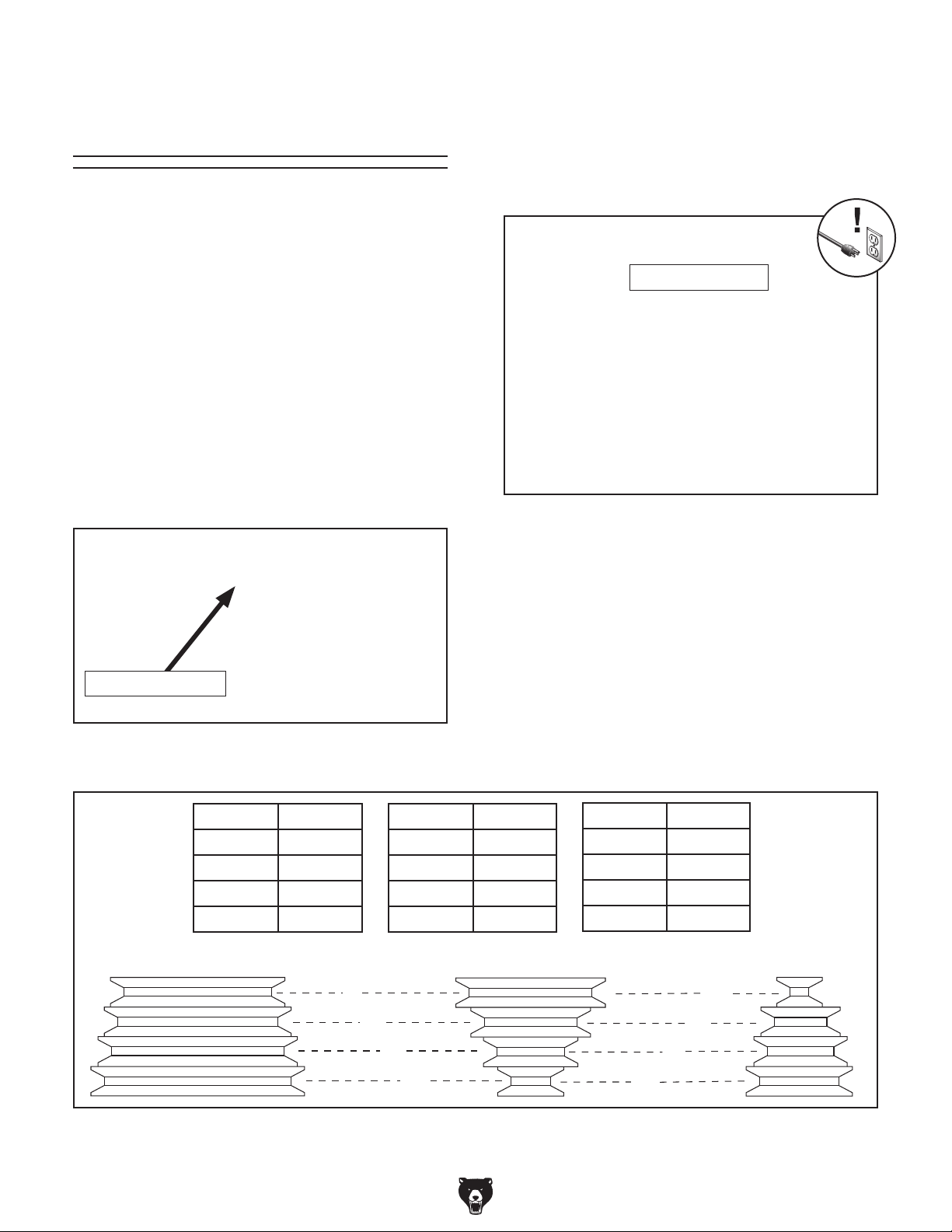
The Model G0823 has 12 spindle speeds, which
are selected by positioning the V-belts in various
configurations on the pulleys. V-belts and pulleys
are located inside the belt cover on top of the
machine.
Tools Needed Qty
Hex Wrench 6mm .............................................. 1
To change spindle speeds:
1. DISCONNECT MACHINE FROM POWER!
2. Loosen motor lock lever shown in Figure
16, pull motor inward to relieve tension on
V-belts, then re-tighten lock lever.
3. Open belt cover, then loosen two idler cap
screws (see Figure 17) that hold idler pulley
in place, so it can move freely.
Tip: Lower headstock for easy access (see
Adjusting Headstock Position on Page 26).
Idler Cap Screws
Figure 17. Spindle speed pulley system.
Motor Lock Lever
Figure 16. Use lock lever when changing V-belt
positions to change spindle speed.
RPM Position
140 4-5
219 3-5
263 4-6
317 2-5
Spindle Pulley Idler Pulley Motor Pulley
1
RPM Position
413 3-6
475 4-7
819 1-6
1075 2-7
4. With center and rear pulleys loose, move
V-belts to corresponding position for desired
speed (see chart below).
5. Loosen motor locking lever and allow spring
to tighten rear V-belt, then re-tighten motor
locking lever.
6. Retighten idler cap screws, then close and
latch belt cover.
RPM Position
1238 3-8
1450 1-7
1770 2-8
2436 1-8
5
-22-
2
3
4
Figure 18. Spindle speed chart.
6
7
8
Model G0823 (Mfd. Since 2/17)
Page 25
Using Downfeed
The Model G0823 features three ways to control
spindle downfeed:
• Coarse Downfeed
• Fine Downfeed
• Auto Downfeed
F. Fine Downfeed Graduated Dial Collar:
Rotate knurled knob to loosen collar. Align
collar depth measurement with indicator line
on headstock. Fine downfeed measurements
are in 0.001".
G. Fine Downfeed Handwheel: Controls spin-
dle travel in slow, small amounts for milling/drilling. Adjusts quill height in 0.001"
increments.
Downfeed Controls
Use Figure 19 and the descriptions below to identify the downfeed controls that are referred to in
the following procedures.
A
F
G
Figure 19. Identification of downfeed controls.
A. Coarse Downfeed Lever (1 of 2): Controls
spindle travel in rapid, large amounts for milling or drilling.
E
B
C
D
Coarse Downfeed
1. Make sure spindle is completely stopped.
2. Loosen depth graduated dial lock handle (C).
3. Rotate depth graduated dial (E) to limit
downfeed depth, then retighten lock handle.
4. Rotate auto-downfeed rate selector knob (B)
counterclockwise to OFF position.
5. Push coarse downfeed handles (A) toward
headstock and tighten coarse handle lockdown thumb screw (D) to hold them in place.
6. Press FORWARD or REVERSE button on
control panel to start spindle rotation, and use
coarse downfeed handles to control spindle
travel.
Fine Downfeed
1. Make sure spindle is completely stopped.
B. Auto-Downfeed Rate Selector Knob:
Adjusts speed of quill vertical movement in
increments of 0.004", 0.008", and 0.012" per
rotation.
C. Depth Graduated Dial Collar Lock: Secures
graduated dial for precise, repeatable drilling
operations.
D. Coarse Downfeed Handle Thumb Screw:
When tightened, secures coarse downfeed
handles for operation. When loosened, allows
coarse downfeed handles to pull outward,
engaging the auto-downfeed function.
E. Coarse Downfeed Graduated Dial Collar:
Adjust collar to specific depth of quill travel
measurements indicated on collar for repeatable drilling operations.
Model G0823 (Mfd. Since 2/17)
2. Loosen depth graduated dial lock handle (C).
3. Loosen coarse handle lock-down thumb
screw (D), and pull coarse downfeed handles
(A) away from headstock.
4. Rotate auto-downfeed rate selector knob (B)
counterclockwise to OFF position.
5. Loosen knurled knob securing fine downfeed
depth graduated dial collar (F) and reset
downfeed depth, then retighten knurled knob.
6. Press FORWARD or REVERSE button on
control panel to start spindle rotation, and
use fine downfeed handwheel (G) to control
spindle travel.
-23-
Page 26

Auto-Downfeed
The auto-downfeed feature uses headstock
gears to control powered downfeed in increments
of 0.10mm, 0.18mm, and 0.26mm per spindle
revolution.
Installing/Removing
Tooling
The Model G0823 includes the spindle tools
shown in Figure 20 below.
Spindle-return is spring-loaded! Do not disengage auto-downfeed until spindle returns
to top (starting) position or spindle will slam
upward into quill.
To use auto-downfeed:
1. Make sure spindle is completely stopped.
2. Ensure work table height is adjusted properly
to allow spindle its full range of movement.
3. Loosen depth graduated dial collar lock (C).
This will disengage coarse downfeed graduated dial collar from operation.
4. Rotate auto-downfeed rate selector knob (B)
clockwise to desired downfeed rate.
5. Loosen coarse handle lock-down thumb
screw (D) and pull coarse downfeed levers
(A) away from headstock.
6. Press FORWARD or REVERSE button on
control panel to start spindle rotation and to
engage auto-downfeed spindle travel.
A. Drill Chuck w/R-8 Arbor: Use with drill bits.
B. R-8–MT#3 Spindle Adapter Sleeve: Use
with MT#3 tooling with or without a tang. Has
a drift key slot for tool removal.
C. MT#3–MT#2 Spindle Adapter Sleeve: Use
with the R-8–MT#3 spindle sleeve for MT#2
tooling. Has a drift key slot for tool removal.
D. Drift Key: Use for tool removal.
A
B
C
D
Figure 20. Drill chuck and arbors included with
Model G0823.
When using auto-downfeed, the spindle
WILL NOT automatically stop or reverse
when it reaches the bottom depth of travel.
To avoid machine damage, manually stop
spindle rotation before this happens.
7. When desired depth of spindle travel is
reached, stop spindle travel by pressing
STOP button on control panel.
8. Firmly grip coarse downfeed handles, push
handles toward headstock, and use handles
to return spindle to top position.
-24-
Cutting tools are sharp and
can easily cause laceration
injuries. Always protect
your hands with leather
gloves or shop rags when
handling cutting tools.
Model G0823 (Mfd. Since 2/17)
Page 27

Installing Tooling
This machine features a spindle that accepts R-8
collets and arbors. It can also use MT#3 or MT#2
tooling with the included adapter sleeves.
6. Continue to tighten drawbar until collet and
cutter (or arbor) are snugged firmly in place.
Do not over-tighten drawbar, and never use
power tools to tighten it.
To install tooling:
1. DISCONNECT MACHINE FROM POWER!
2. Open belt cover.
3. Make sure tapered mating surfaces of tooling
and spindle are clean and free of grease or
other contaminants.
4. Align tooling alignment slot (see Figure 21)
with pin inside spindle, then insert tooling into
spindle until it contacts drawbar.
Note: Drawbar height inside spindle can be
changed by rotating the drawbar lock nut (see
Figure 21).
5. Working from the top, hand-thread drawbar
into tooling until finger-tight, then use a lug
wrench to snug it.
—If drawbar bottoms out in tooling and will
not tighten further before tooling is tight
in spindle, tighten drawbar lock nut (see
Figure 21) to secure tooling in spindle.
Removing Tooling
1. DISCONNECT MACHINE FROM POWER!
2. Loosen, but do not remove, drawbar.
Tip: If necessary, insert included drill chuck
key into chuck to hold chuck in place when
tightening drawbar.
3. Hold tooling to prevent it from dropping completely out of machine. Tap on top of drawbar
with a brass hammer to loosen collet/arbor
from spindle, as shown in Figure 22.
Brass Hammer
Note: DO NOT overtighten drawbar.
Overtightening makes tooling removal difficult and could damage arbor and drawbar
threads.
Lug Wrench
Drawbar
Lock Nut
Arbor
Figure 21. Threading drawbar into collet/arbor to
install tooling.
Drawbar
Drawbar
Arbor
Figure 22. Tapping top of drawbar with drawbar
nut already loosened to remove tooling.
4. Unthread drawbar until it is free from tooling.
Remove tooling from spindle when not in use.
Model G0823 (Mfd. Since 2/17)
-25-
Page 28

Adjusting Headstock
Position
The headstock travels up and down the column,
and rotates 360° around the column. Before
adjusting headstock position, fully retract the
quill and set the headstock as low as possible to
increase quill rigidity and reduce vibration.
Setting Depth Stop
The depth stop is used to limit the range of tooling
downward movement or drilling depth. Maximum
depth is 5
To set depth stop:
1. DISCONNECT MACHINE FROM POWER!
1
⁄8".
To adjust headstock position:
1. DISCONNECT MACHINE FROM POWER!
2. Use included lug wrench to loosen both
headstock lock nuts shown in Figure 23.
Headstock
Lock Nuts
Figure 23. Loosening headstock lock nuts in
order to adjust headstock position.
3. Use headstock elevation crank (see Figure
24) to move head up or down as desired. Use
your hands to rotate headstock on column as
needed.
2. Install tooling (refer to Page 25), then make
sure spindle is drawn all the way up into
headstock.
3. Loosen headstock lock nuts (see Figure 23)
and lower head using headstock elevation
crank (see Figure 24) until drill bit or cutter
is approximately
retighten headstock lock nuts.
4. Rotate knurled knob (Figure 25) until top of
indicator is level with desired depth as listed
on scale.
Note: The depth stop scale functions as a
general guide only. It is not intended for hightolerance, precision results. To calibrate the
depth stop, see Calibrating Depth Stop on
Page 36.
1
⁄8" above workpiece, then
Headstock
Elevation Crank
Figure 24. Location of headstock elevation
crank.
4. Retighten headstock lock nuts.
-26-
Indicator
Knurled
Knob
Figure 25. Depth stop controls.
Model G0823 (Mfd. Since 2/17)
Page 29

Positioning Table
Pivoting Table Around Column
1. Remove any loose objects from table surface.
The table moves vertically, rotates 360°, pivots
around the column, and tilts 60° left or right.
Rotating Table on Its Axis
1. Remove any loose objects from table surface.
2. Loosen pivot lock handle shown in Figure 26.
Pivot Lock
Handle
Rack
Table Lock
Handles
Table Elevation
Crank
2. Slightly loosen table lock handles (see
Figure 26).
3. Pivot table to desired location, making sure to
guide rack, as shown in Figure 26.
4. Retighten lock handles.
Tilting Table
1. Remove all objects from table surface.
2. Loosen three tilt lock nuts shown in Figure 27.
Tilt Lock
Nuts
Tilt Angle
Pointer and Scale
Figure 26. Table adjustment controls.
3. Rotate table to desired position, then re-
tighten pivot lock handle.
Raising/Lowering Table
1. Remove any loose objects from table surface.
2. Loosen table lock handles shown in Figure 26.
3. Adjust table height by rotating table elevation
crank (see Figure 26), then re-tighten table
lock handles.
Figure 27. Table tilt controls.
3. Tilt table until pointer aligns with desired
angle on scale (see Figure 27).
4. Retighten tilt-lock nuts.
Model G0823 (Mfd. Since 2/17)
-27-
Page 30

ACCESSORIES
Installing unapproved accessories may
order online at www.grizzly.com or call 1-800-523-4777
SECTION 5: ACCESSORIES
cause machine to malfunction, resulting in
serious personal injury or machine damage.
To reduce this risk, only install accessories
recommended for this machine by Grizzly.
NOTICE
Refer to our website or latest catalog for
additional recommended accessories.
G5753— 6" Cast-Iron Drill Press Vise
If you use a drill press and value your fingers, you
need one of these. Made from high-grade cast
iron, these hefty horizontal vises offer support
and stability, allowing you to keep your hands well
away from fast moving bits and cutters. Includes
a sturdy lip along both sides of the base, allowing
vise to be mounted to nearly any machine table,
using common T-slot clamps.
G1075—52-Pc. Clamping Kit
This clamping kit includes 24 studs, 6 step block
pairs, 6 T-nuts, 6 flange nuts, 4 coupling nuts, and
6 end hold-downs. The rack is slotted so it can be
mounted close to the machine for easy access.
Made for
T20501—Face Shield Crown Protector 4"
T20502—Face Shield Crown Protector 7"
T20503—Face Shield Window
T20451—"Kirova" Clear Safety Glasses
T20452—"Kirova" Anti-Reflective S. Glasses
H0736—Shop Fox
H7194—Bifocal Safety Glasses 1.5
H7195—Bifocal Safety Glasses 2.0
H7196—Bifocal Safety Glasses 2.5
1
⁄2 " T-slots.
Figure 29. G1075 Clamping Kit.
®
Safety Glasses
Figure 28. G5753 6" Cast-Iron Drill Press Vise.
Figure 30. Safety glasses.
-28-
Model G0823 (Mfd. Since 2/17)
Page 31

G3658—Titanium Drill Bits
order online at www.grizzly.com or call 1-800-523-4777
Titanium nitride-coated bits last up to six times as
long as uncoated bits. This 115-piece set features
1
29 fractional bits, from
1
⁄64", letter bits from A–Z, and 60 number bits.
of
⁄16" to 1⁄2 " in increments
Housed in rugged steel case.
G1064—Cross-Sliding Vise
This vise features an exclusive slide bar to prevent
the jaws from tilting up or sideways when tightening. Adjustable gibs take up any slack on both top
and bottom slides. Use this vise on your drill press
for cutting keyways and doing light milling jobs.
Figure 31. G3658 115-Pc. Drill Bit Set.
T26688—R-8 Quick-Change Collet 8-Pc. Set
These collets are hardened and ground for maximum holding power and ultra precision. Threaded
7
⁄16"-20 draw bars, this set has a maximum run-
for
out of 0.001". Set includes collect chuck,
3
⁄8", 1⁄2 ", 5⁄8", 3⁄4", and 1" collets, spanner wrench,
1
⁄4", 5⁄16",
and moulded plastic case.
Figure 33. G1064 Cross-Sliding Vise.
T24354—6" Digital Caliper with 6" Digital
Micrometer Set
This high-precision electronic Outside Micrometer
features a crisp, clear, easy-to-read LCD display,
and is accurate to 0.001". Hardened and ground
spindle with carbide anvil ensures durability and
accuracy.
Figure 32. T26688 R-8 Quick-Change Collet
8-Pc. Set.
Figure 34. Model T24354 6" Digital Caliper with
1" Digital Micrometer Set.
Model G0823 (Mfd. Since 2/17)
-29-
Page 32

3
H7362—Drill Doctor DD500x Home/Shop
1
⁄2" Drill Sharpener
⁄32"–
Save yourself money by sharpening you dull and
broken drill bits at home! This easy-to-use system
makes it simple to keep a sharp, perfectly angled
cutting edge on bits you use often, and it can even
be used to put an edge back on broken bits.
®
H3788—G96
G2871—Boeshield
H5486—SLIPIT
Gun Treatment
®
T-9
®
Keep unpainted cast iron surfaces rust-free with
®
regular applications of products like G96
®
Treatment, SLIPIT
, or Boeshield® T-9.
Gun
Figure 35. H7362 Drill Doctor drill bit sharpener.
Cutting Fluid Products
SB1366—South Bend Cutting Oil, 12 oz.
H7617— High-Pressure 5 oz. Oil Can w/Flex Nozzle
T10615—Viper's Venom Cutting Oil, 1 Qt.
T24918 & T24919—Slugger Cutting Fluid, 1 Qt.
& Slugger Cutting Paste
Protect your drill press and cutting tools with
superior cutting fluid products from Grizzly.com.
H7617
SB1366
T24919
H3788
G96
®
Gun
G2870
Boeshield
®
T-9
G5562
SLIPIT
®
Trea tme nt
Figure 37. Lubrication options.
T26685—ISO32 Moly-D Multi-Function Oil
T26419—Syn-o-Gen High-Speed Bearing
Grease Moly-D
Moly-D lubricants are some of the best we've
found for maintaining the critical components of
machinery because they tend to resist run-off
and maintain their lubricity under a variety of
conditions.
T26419
T10615
T24918
Figure 36. Cutting fluid options from Grizzly.
-30-
T26685
Figure 38. ISO-32 T26685 Moly-D Oil and
T26419 Armor Plate NLGI#2 Moly-D Grease.
Model G0823 (Mfd. Since 2/17)
Page 33
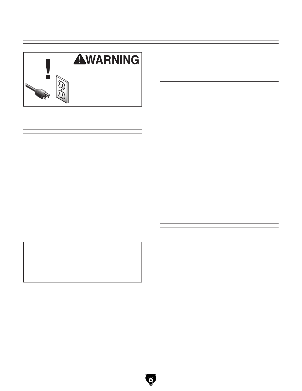
SECTION 6: MAINTENANCE
Cleaning &
Always disconnect power
to the machine before
performing maintenance.
Failure to do this may
result in serious personal injury.
Schedule
For optimum performance from your machine,
follow this maintenance schedule and refer to any
specific instructions given in this section.
Daily Check
• Make sure drill is disconnected from power
when not in use.
• Check for loose mounting bolts.
• Make sure drill is clean and lubricated.
• Check for worn or damaged wires.
• Check for any other unsafe condition.
• Check belts for tension and wear.
Every 90 Days
• Lubricate quill surface and column racks.
Protecting
Sawdust, wood chips, and metal chips left on the
machine will invite oxidation and a gummy residue
buildup around the moving parts. Use a brush and
shop vacuum to remove chips and debris from the
working surfaces of the drill. Never blow off the
drill with compressed air, as this will force metal
chips deep into the mechanisms and may cause
injury to yourself or bystanders.
Remove any rust build-up from unpainted castiron surfaces of your drill and treat them with a
non-staining lubricant after cleaning.
Keep unpainted cast-iron surfaces rust-free
with regular applications of products like G96
Gun Treatment, SLIPIT
Accessories on Page 30).
®
, or Boeshield® T-9 (see
Lubrication
An essential part of lubrication is cleaning the
components before lubricating them.
®
NOTICE
Follow reasonable lubrication practices as
outlined in this manual. Failure to do so
could lead to premature failure of your
machine and will void the warranty.
Model G0823 (Mfd. Since 2/17)
This step is critical because grime and chips build
up on lubricated components, which makes them
hard to move. Simply adding more lubricant will
not result in smooth moving parts.
Clean all exterior components in this section with
mineral spirits, shop rags, and brushes before
lubricating.
DISCONNECT MACHINE FROM POWER
BEFORE PERFORMING LUBRICATION.
-31-
Page 34
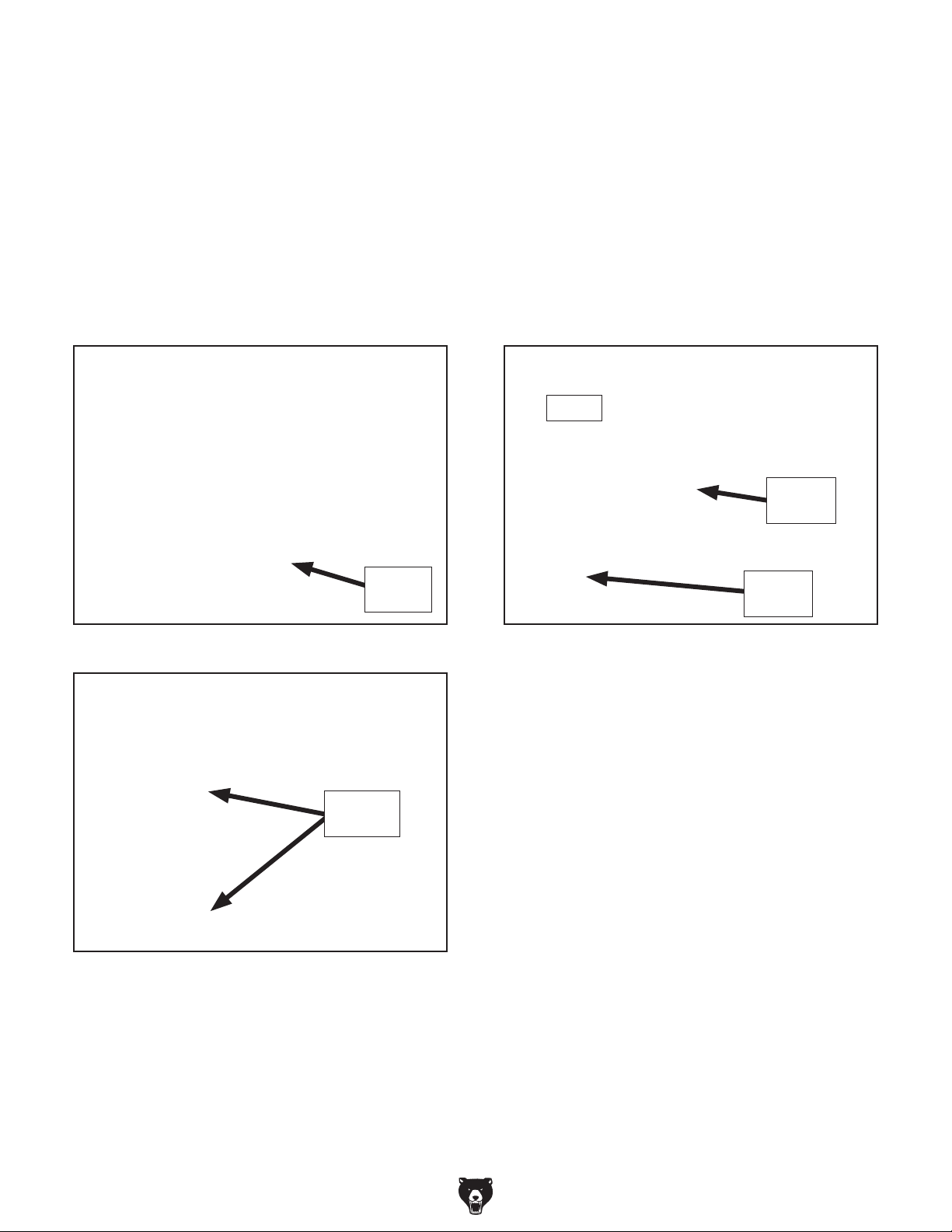
Quill & Column Surfaces
Oi l Ty pe ......Model T23962 or ISO 68 Equivalent
Oil Amount ............................................Thin Coat
Lubrication Frequency ...........8 Hrs. of Operation
Column Rack, Quill Rack & Pinion
Gre ase Ty pe ......... NLGI#2 Grease or Equivalent
Grease Amount ....................................Thin Coat
Lubrication Frequency ......... 90 hrs. of Operation
Use the controls to access the entire smooth
surfaces of the quill and column (see Figures
39–40), then clean them with mineral spirits and
shop rags.
Note: Avoid removing the grease from the column
racks during cleaning.
Quill
Surface
Figure 39. Quill surface location.
Move the quill up and down to gain full access to
the quill rack & pinion (see Figure 41), then clean
the teeth with mineral spirits, shop rags, and a
brush.
Next, clean the column rack teeth with mineral
spirits, shop rags, and a brush.
Pinion
Quill
Rack
Column
Rack
Figure 41. Quill rack & pinion locations.
Column
Surfaces
Figure 40. Column surface locations.
When dry, apply a thin coat of oil to the surfaces.
Move the components through the entire path of
travel to distribute the lubricant.
When dry, use a brush to apply a thin coat of
grease to the teeth, then raise/lower the quill to
distribute the grease.
Note: Re-apply oil to the quill smooth outside
surface that was removed during the cleaning
process.
-32-
Model G0823 (Mfd. Since 2/17)
Page 35

Troubleshooting
SECTION 7: SERVICE
Review the troubleshooting and procedures in this section to fix or adjust your machine if a problem develops. If you need replacement parts or you are unsure of your repair skills, then feel free to call our Technical
Support at (570) 546-9663.
Troubleshooting
Motor & Electrical
Symptom Possible Cause Possible Solution
Machine does not
start or a breaker
trips.
Machine stalls or is
underpowered.
Machine has
vibration or noisy
operation.
1. Plug/receptacle at fault/wired wrong.
2. Incorrect power supply voltage or circuit
size.
3. Power supply circuit breaker tripped or fuse
blown.
4. Motor wires connected incorrectly.
5. Wiring open/has high resistance.
6. Spindle direction switch at fault.
7. Start capacitor at fault.
8. Centrifugal switch at fault.
9. Motor at fault.
1. Incorrect/dull cutter/bit for task.
2. Feed rate/cutting speed too fast.
3. Belt(s) slipping.
4. Machine undersized for task.
5. Plug/receptacle at fault.
6. Motor overheated.
7. Run capacitor at fault.
8. Pulley slipping on shaft.
9. Centrifugal switch at fault.
10. Motor bearings at fault.
1. Motor or other drive component loose.
2. V-belt(s) worn or loose.
3. Motor fan rubbing on fan cover.
4. Pulley loose.
5. Machine incorrectly mounted to floor.
6. Motor mount loose/broken.
7. Motor bearings at fault.
8. Chuck unbalanced or cutter dull.
9. Centrifugal switch out of adjustment or at
fault.
1. Test for good contacts; correct the wiring.
2. Ensure correct power supply voltage and circuit
size.
3. Ensure circuit is sized correctly and free of shorts.
Reset circuit breaker or replace fuse.
4. Correct motor wiring connections.
5. Check/fix broken, disconnected, or corroded wires.
6. Replace switch.
7. Test/replace.
8. Adjust/replace centrifugal switch if available.
9. Test/repair/replace.
1. Use correct cutter/bit.
2. Decrease feed rate/cutting speed.
3. Ensure belts are oil free, tension/replace belt(s);
ensure pulleys are aligned.
4. Perform operation with different machine.
5. Test for good contacts/correct wiring.
6. Clean motor, let cool, and reduce workload.
7. Test/repair/replace.
8. Tighten loose pulley; replace broken/missing parts.
9. Adjust/replace centrifugal switch if available.
10. Test/repair/replace.
1. Inspect/replace damaged bolts/nuts, and retighten
with thread-locking fluid, if necessary.
2. Inspect/replace belts with a new matched set.
3. Fix/replace fan cover; replace loose/damaged fan.
4. Re-align/replace shaft, pulley set screw, and key.
5. Tighten mounting bolts; relocate/shim machine.
6. Tighten/replace.
7. Test by rotating shaft; rotational grinding/loose
shaft requires bearing replacement.
8. Replace chuck; replace/resharpen cutter.
9. Adjust or replace.
Model G0823 (Mfd. Since 2/17)
-33-
Page 36

Drill Press Operations
Symptom Possible Cause Solution
Tool loose/lack of
power in spindle.
Workpiece or tool
vibrates or chatters
during operation.
Headstock is hard to
raise.
Bad surface finish. 1. Spindle speed too fast for workpiece
Spindle overheats. 1. Drill operated at high speeds for extended
Spindle does not
return to highest
position.
Depth stop producing inaccurate
results.
1. Tool incorrectly installed in spindle taper.
2. Debris on tool or spindle taper mating
surfaces.
3. Taking too big of a cut.
4. V-belts are loose.
5. Wrong voltage.
1. Table locks not tight.
2. Workpiece not secure.
3. Spindle speed/feed rate is too fast.
4. Spindle or quill extended too far down.
5. Quill lock lever not tight.
1. Headstock lock nuts at fault.
2. Rack and pinion at fault or jammed with
grime/debris.
material.
2. Dull or incorrect cutting tool.
3. Wrong rotation direction of cutting tool.
4. Workpiece not secure.
5. Spindle extended too far down during
operation.
period.
1. Poorly adjusted return spring.
2. Worn return spring.
1. Depth stop not calibrated. 1. Calibrate depth stop (Page 36).
1. Remove and re-install, as instructed on Page 25.
2. Clean tool and spindle taper.
3. Reduce depth of cut and allow chips to clear.
4. Properly tension V-belts.
5. Correct voltage.
1. Tighten table locks (Page 27).
2. Properly clamp workpiece on table or in vise.
3. Set spindle speed correctly (Page 22) or use
slower feed rate.
4. Fully retract spindle and lower headstock. This
increases rigidity to decrease vibration.
5. Tighten quill lock lever.
1. Loosen/replace lock nuts.
2. Fix/replace broken or loose parts; clean and
lubricate rack and pinion.
1. Set spindle speed correctly (Page 22).
2. Sharpen cutting tool or select one that better suits
the operation.
3. Check for proper cutting tool rotation.
4. Properly clamp workpiece on table or in vise.
5. Fully retract spindle and lower headstock. This
increases rigidity.
1. Allow drill to cool.
1. Increase return spring tension (Page 35).
2. Replace return spring.
-34-
Model G0823 (Mfd. Since 2/17)
Page 37
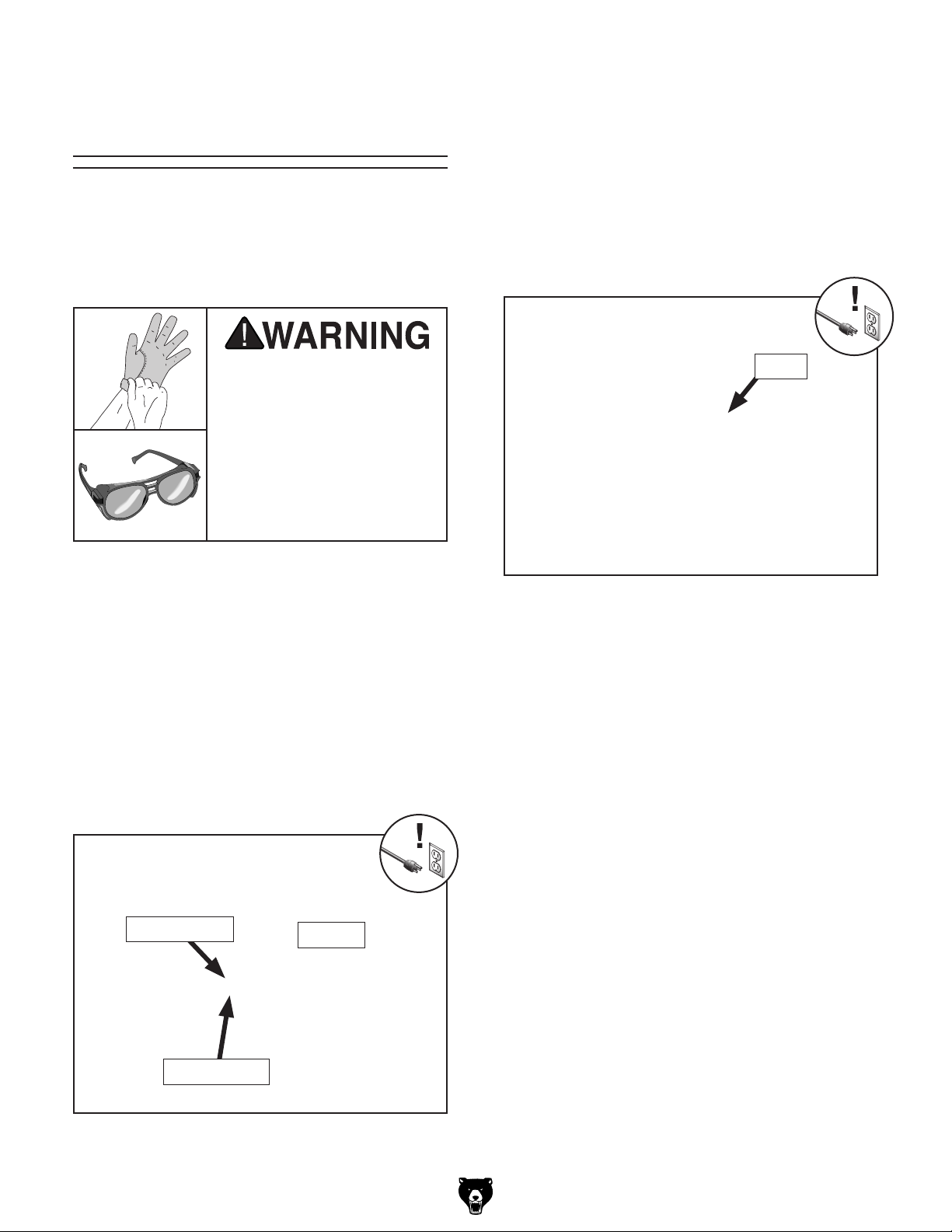
Tensioning Return
Spring
4. Wearing gloves, pull spring cover (see Figure
43) out enough so notches just clear roll pin.
HOLD SPRING COVER TIGHTLY during this
step, or force of spring will cause cover to
spin out of your hands.
The spring tension for automatic quill recoil has
been pre-set at the factory. It should not need
adjustment under most normal circumstances. If
it does need adjustment, the spring housing is
located on the left side of the headstock.
If the return spring should
come loose from the spring
cap and rapidly unwind,
laceration or impact injuries could occur. Always
wear heavy leather gloves
and safety glasses when
adjusting the return spring
tension.
Items Needed Qty
Heavy Leather Gloves ................................ 1 Pair
Safety Glasses ...........................................1 Pair
5. Rotate cover counterclockwise to increase
tension, then push cover back in to engage
roll pin with one of the notches, as shown in
Figure 43.
Notch
Figure 43. Adjusting spring tension by rotating
spring cover to engage next notch with roll pin.
To adjust spring tension:
1. DISCONNECT MACHINE FROM POWER!
2. PUT ON SAFETY GLASSES!
3. Loosen thumb knob (see Figure 42) 2–3 turns.
DO NOT completely remove thumb knob.
Spring Cover
Thumb Knob
Roll Pin
6. Tighten thumb knob.
7. Check return spring tensioning by rotating
coarse downfeed handwheel. Spindle should
return quickly when downward pressure is
released.
— If spindle does not retract quickly, repeat
Steps 3–6, and re-check tension until
return speed is adequate.
Figure 42. Spring tension components.
Model G0823 (Mfd. Since 2/17)
-35-
Page 38

Calibrating Depth
Stop
Note: Indicator plate may extend below "0"
hash mark when it reaches bottom of travel.
Depth stop accuracy may be improved by calibrating the depth stop. See Figure 44 for depth stop
components. Make sure the spindle is retracted
all the way into the quill, then follow the steps
below.
To ensure accuracy over time, re-check "0" of
depth stop periodically.
Note: The depth stop scale functions as a general
guide only. It is not intended for high-tolerance,
precision results. See Accessories on Page 28
for precision depth indicator options.
Tool Needed Qty
Hex Wrench 2.5mm ........................................... 1
Depth Stop
Indicator
Depth Stop
Scale
Adjustment
Dial
Figure 44. Depth stop components.
Indicator
Plate
Figure 45. Depth stop set at "0" for calibration.
2. Loosen cap screw shown in Figure 45, and
position indicator plate so upper edge of plate
aligns with "0" on the scale, then re-tighten
cap screw to secure setting.
Cap
Screw
V-Belts
Inspect regularly for tension and wear. Refer to
Figure 46 for proper belt tension. Belt deflection should be approximately
pressure. Replacement V-belts can be found in
the back of this manual in the part breakdowns.
Check pulleys to ensure that they are properly
aligned when installing V-belts.
To replace the V-belts, refer to Changing Spindle
Speed on Page 22 to loosen the belts. Remove
them from the pulleys, then install new V-belts.
1
⁄4" under moderate
To calibrate depth stop:
1. Rotate depth stop adjustment knob to lower
depth stop (see Figure 45) until indicator
plate reaches bottom of its travel.
-36-
1
⁄4"
Deflection
Figure 46. Inspecting belt tension.
Model G0823 (Mfd. Since 2/17)
Pulley
Pulley
Page 39

These pages are current at the time of printing. However, in the spirit of improvement, we may make changes to the electrical systems of future machines. Compare the manufacture date of your machine to the one
number and manufacture date of your
machine before calling. This information can be found on the main machine label.
machine
SECTION 8: WIRING
stated in this manual, and study this section carefully.
If there are differences between your machine and what is shown in this section, call Technical Support at
(570) 546-9663 for assistance BEFORE making any changes to the wiring on your machine. An updated
wiring diagram may be available. Note: Please gather the serial
Wiring Safety Instructions
SHOCK HAZARD. Working on wiring that is con-
nected to a power source is extremely dangerous.
Touching electrified parts will result in personal
injury including but not limited to severe burns,
electrocution, or death. Disconnect the power
from the machine before servicing electrical components!
MODIFICATIONS. Modifying the wiring beyond
what is shown in the diagram may lead to unpredictable results, including serious injury or fire.
This includes the installation of unapproved aftermarket parts.
WIRE CONNECTIONS. All connections must
be tight to prevent wires from loosening during
machine operation. Double-check all wires disconnected or connected during any wiring task to
ensure tight connections.
CIRCUIT REQUIREMENTS. You MUST follow
the requirements at the beginning of this manual
when connecting your machine to a power source.
WIRE/COMPONENT DAMAGE. Damaged wires
or components increase the risk of serious personal injury, fire, or machine damage. If you notice
that any wires or components are damaged while
performing a wiring task, replace those wires or
components.
MOTOR WIRING. The motor wiring shown in
these diagrams is current at the time of printing
but may not match your machine. If you find this
to be the case, use the wiring diagram inside the
motor junction box.
CAPACITORS/INVERTERS. Some capacitors
and power inverters store an electrical charge for
up to 10 minutes after being disconnected from
the power source. To reduce the risk of being
shocked, wait at least this long before working on
capacitors.
EXPERIENCING DIFFICULTIES. If you are experiencing difficulties understanding the information
included in this section, contact our Technical
Support at (570) 546-9663.
The photos and diagrams
included in this section are
best viewed in color. You
can view these pages in
color at www.grizzly.com.
Model G0823 (Mfd. Since 2/17)
READ ELECTRICAL SAFETY
ON PAGE 37!
-37-
Page 40
Electrical Components
Motor
Junction
Box
Control
Motor
Figure 47. Electrical component overview.
Panel
Electrical
Box
Control Panel
Reverse
Button
Forward
Button
Indicator
Light
Figure 48. Motor junction box wiring.
E-Stop
Stop
Button
Figure 49. Control panel wiring.
-38-
Figure 50. Electrical box wiring.
READ ELECTRICAL SAFETY
ON PAGE 37!
Model G0823 (Mfd. Since 2/17)
Page 41
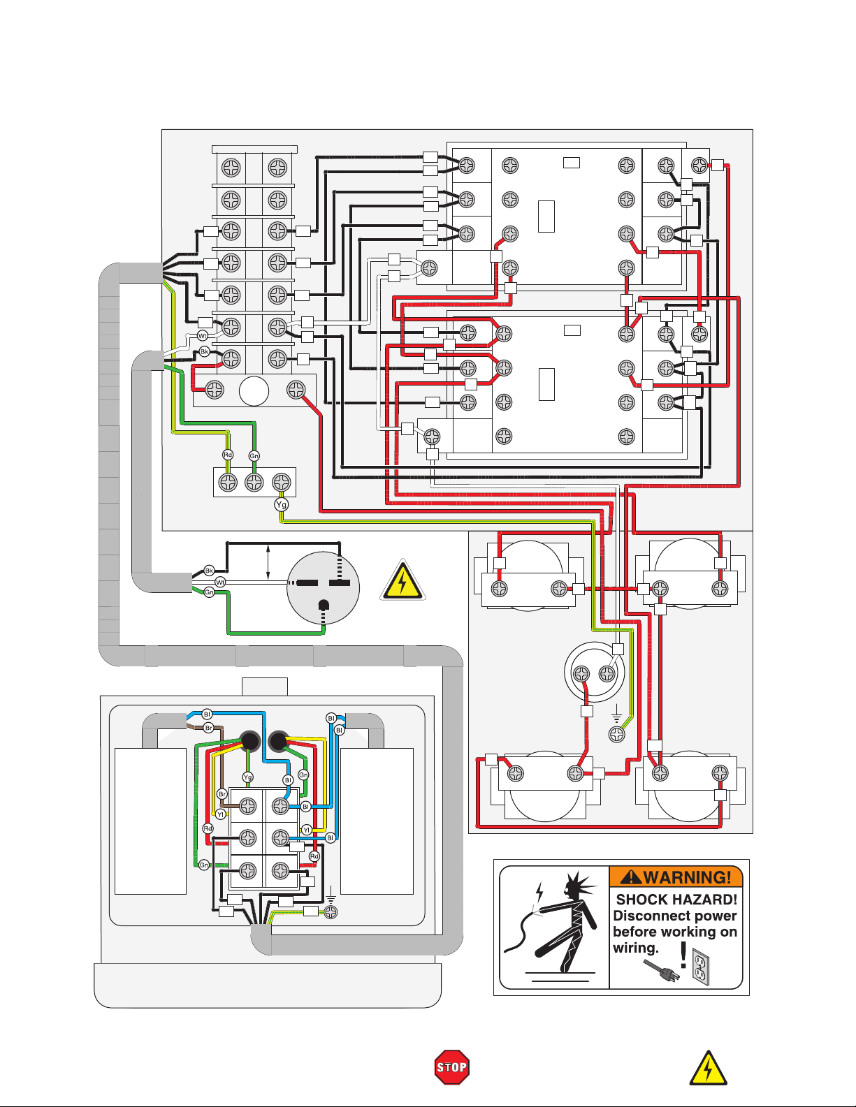
Ground
Wiring Diagram
U1
V1
U2
V2
250V
Fuse
2A
Electrical Box
V1
U2
V2
0
N
L
SIEMENS
3TB41
13NO 21NC 31NC 43NO
Contactor
1L1 3L2 5L3
8
A1
N
L
6
L
14NO 22NC 32NC 44NO
22E
KM1
264V
Coil
A2
2T1 4T2 6T3
7
V1
V1
U2
U2
V2
V2
0
0
5
4
4
1L1 3L2 5L3
6
N
8
A1
N
L
L
SIEMENS
3TB41
13NO 21NC 31NC 43NO
Contactor
V2
U2
14NO 22NC 32NC 44NO
2T1 4T2 6T3
7
5
22E
KM2
5
V1
264V
A2
0
Coil
0
Start
Capacitor
150 MFD
250 VAC
220
VAC
Ground
V1
U2
Hot
V2
U2 V1
Z1
Z2
Z1
W1
U2
U1
Hot
V2
V2
G
(As Recommended)
Run
Capacitor
20 MFD
450 VAC
U1
PE
6-15 Plug
7
Reverse
Minger 3A 240V
3
NO
LA125H-BE101C
Indicator Light
2
Minger 3A 240V
LA125H-BE102C
E-Stop
4
4 4
X2
1
NC
12
X1
1
0
GND
Forward
Minger 3A 240V
3
NO
LA125H-BE101C
4
Control Panel
(Viewed from Behind)
4
Minger 3A 240V
NC
LA125H-BE102C
Stop
5
4
12
2
220V Motor
Model G0823 (Mfd. Since 2/17)
READ ELECTRICAL SAFETY
ON PAGE 37!
-39-
Page 42

SECTION 9: PARTS
Headstock
2
60
103
100-2
100-3
102-1
102-3
102-4
102-5
59
6
7
8
9
8
11
61
100-1
100-4
100-5
102
101
100
102-2
3
98
74
3
73
75
97
71
4
66
65
5
64
63
62
43
44
45
46
42
47
35
36
34
33
32
31
30
48
49
37
69
85
68
67
50
29
28
49
72
71
70
76
52
51
14
15
16
12
13
52
10
10
94
91
89
95
90
92
23
93
96
91
17
18
19
83-2
83-5
80
86
87
1
38
83-1
79
39
88
55
53
56
54
83-3
83-8
78
57
83
40
58
83-4
83-9
77
83-6
84
104
99
83-7
105
41
81
82
-40-
103
27
24
25
22
20
21
26
Model G0823 (Mfd. Since 2/17)
Page 43

Headstock Parts
REF PART # DESCRIPTION REF PART # DESCRIPTION
1 P0823001 HEAD CASTING 53 P0823053 FLAT WASHER 16MM
2 P0823002 DRAWBAR 7/16-20 X 17-3/4 54 P0823054 HEX NUT M16-2
3 P0823003 SPANNER NUT M42-1.5 55 P0823055 ADJUSTABLE HANDLE 45L M8-1.25 X 36
4 P0823004 SPINDLE PULLEY 56 P0823056 COMPRESSION SPRING
5 P0823005 SPINDLE TAPER SLEEVE 57 P0823057 BELT TENSION ROD
6 P0823006 CAP SCREW M5-.8 X 12 58 P0823058 BELT TENSION CAP (RUBBER)
7 P0823007 OUTER BEARING PLATE 59 P0823059 BELT COVER
8 P0823008 BALL BEARING 6009ZZ 60 P0823060 BELT COVER GUARD
9 P0823009 SPACER 74MM 61 P0823061 DRAWBAR COVER
10 P0823010 INT RETAINING RING 75MM 62 P0823062 FLAT WASHER 8MM
11 P0823011 EXT RETAINING RING 45MM 63 P0823063 HEX BOLT M8-1.25 X 20
12 P0823012 SPANNER NUT M30-1.5 64 P0823064 PULLEY IDLER PLATE
13 P0823013 EXT TOOTH WASHER 30MM 65 P0823065 FLAT WASHER 8MM
14 P0823014 TAPERED ROLLER BEARING 30206 66 P0823066 CAP SCREW M8-1.25 X 40
15 P0823015 RUBBER FLANGE 67 P0823067 HEX NUT M16-2
16 P0823016 QUILL 68 P0823068 FLAT WASHER 16MM
17 P0823017 TAPERED ROLLER BEARING 30207 69 P0823069 IDLER PULLEY SHAFT
18 P0823018 BEARING COVER 70 P0823070 IDLER PULLEY
19 P0823019 SPINDLE R-8 71 P0823071 BALL BEARING 6204Z
20 P0823020 SET SCREW M5-.8 X 6 DOG-PT 72 P0823072 INT RETAINING RING 47MM
21 P0823021 SET SCREW M5-.8 X 6 73 P0823073 FLAT WASHER 16MM
22 P0823022 QUILL CLAMP 74 P0823074 HEX NUT M16-2
23 P0823023 CAP SCREW M8-1.25 X 30 75 P0823075 V-BELT A33
24 P0823024 INT THREADED BOLT M16-2 X 20 76 P0823076 V-BELT A39
25 P0823025 KNURLED THUMB SCREW M12-1.75 77 P0823077 MOTOR MOUNT
26 P0823026 ROLL PIN 3 X 18 78 P0823078 HEX BOLT M12-1.75 X 25
27 P0823027 HEX NUT M16-2 THIN 79 P0823079 FLAT WASHER 8MM
28 P0823028 DEPTH GAUGE LEADSCREW M12-1.75 X 230 80 P0823080 HEX NUT M8-1.25
29 P0823029 DEPTH ROD DOG 81 P0823081 FLAT WASHER 8MM
30 P0823030 BUTTON HD CAP SCR M4-.7 X 6 82 P0823082 HEX BOLT M8-1.25 X 30
31 P0823031 DEPTH POINTER 83 P0823083 MOTOR 2HP 220V 1-PH
32 P0823032 FRONT COVER 83-1 P0823083-1 MOTOR FAN COVER
33 P0823033 FLAT WASHER 5MM 83-2 P0823083-2 MOTOR FAN
34 P0823034 CAP SCREW M5-.8 X 12 83-3 P0823083-3 R CAPACITOR 20M 450V 1-5/8 X 3-1/4
35 P0823035 QUILL LOCK HANDLE 116L M10-1.5 X 60 83-4 P0823083-4 S CAPACITOR 150M 250V 1-5/8 X 3
36 P0823036 OUTER QUILL CLAMP 83-5 P0823083-5 CONTACT PLATE
37 P0823037 INNER QUILL CLAMP 83-6 P0823083-6 CETRIFUGAL SWITCH 1720 RPM
38 P0823038 GEARBOX COVER 83-7 P0823083-7 MOTOR JUNCTION BOX
39 P0823039 CAP SCREW M8-1.25 X 25 83-8 P0823083-8 BALL BEARING 6205Z (FRONT)
40 P0823040 SPINDLE AUTO DOWNFEED ASSY 83-9 P0823083-9 BALL BEARING 6205Z (REAR)
41 P0823041 CAP SCREW M8-1.25 X 85 84 P0823084 KEY 8 X 8 X 25
42 P0823042 EXT RETAINING RING 18MM 85 P0823085 MOTOR PULLEY SET
43 P0823043 KNOB BOLT M8-1.25 X 12 86 P0823086 ELEVATION CRANK BRACKET
44 P0823044 BUSHING 87 P0823087 WORM SHAFT BUSHING
45 P0823045 SPRING COVER 88 P0823088 ELEVATION WORM SHAFT
46 P0823046 FLAT COIL SPRING 89 P0823089 ELEVATION GEAR SHAFT
47 P0823047 CAP SCREW M6-1 X 12 90 P0823090 HELICAL GEAR 15T
48 P0823048 SPRING BASE 91 P0823091 EXT RETAINING RING 14MM
49 P0823049 ROLL PIN 3 X 12 92 P0823092 ELEVATION CRANK
50 P0823050 CAP SCREW M10-1.5 X 10 93 P0823093 SET SCREW M10-1.5 X 10
51 P0823051 SET SCREW M10-1.5 X 12 94 P0823094 REVOLVING HANDLE 75L, 12 X 22
52 P0823052 CLAMPING BOLT M16-2 X 178 95 P0823095 SHOULDER SCR M10-1.5 X 12, 12 X 68
Model G0823 (Mfd. Since 2/17)
-41-
Page 44

Headstock Parts Cont.
REF PART # DESCRIPTION REF PART # DESCRIPTION
96 P0823096 CAP SCREW M6-1 X 20 101 P0823101 ELECTRICAL CABINET SIDE COVER
97 P0823097 PULLEY 102 P0823102 ELECTRICAL CABINET FRONT COVER
98 P0823098 FLAT HD SCR M5-.8 X 10 102-1 P0823102-1 BUTTON SWITCH MING LA125H 22MM GRN
99 P0823099 ROUND BELT 8 X 670 102-2 P0823102-2 BUTTON SWITCH MING LA125H 22MM GRN
100 P0823100 ELECTRICAL CABINET 102-3 P0823102-3 INDICATOR LIGHT MING A62-22D/S 22MM GRN
100-1 P0823100-1 CONTACTOR SIEMENS 3TB41 22-0X 220V 102-4 P0823102-4 BUTTON SWITCH MING LA125H 22MM RED
100-2 P0823100-2 TERMINAL 7P 102-5 P0823102-5 E-STOP BUTTON MING LA125H 22MM
100-3 P0823100-3 GROUNDING PLATE 3P 103 P0823103 BUTTON HD CAP SCR M4-.7 X 8
100-4 P0823100-4 STRAIN RELIEF TYPE-3 M18-1.5 104 P0823104 POWER CORD 14G 3W 72"
100-5 P0823100-5 STRAIN RELIEF TYPE-5 M20-1.5 105 P0823105 CONDUIT 21 X 420MM RIBBED
-42-
Model G0823 (Mfd. Since 2/17)
Page 45

Base
209
207
212
213
208
210
202
203
219
221
224
225
218
205
217
222
221
241
220
240
204
242
243
244
247
201
243
245
211
248
246
249
206
226
250
214
Model G0823 (Mfd. Since 2/17)
215
216
-43-
Page 46

Base Parts
REF PART # DESCRIPTION REF PART # DESCRIPTION
201 P0823201 BASE CASTING 219 P0823219 HANDLE 130L M10-1.5 X 10
202 P0823202 COLUMN 220 P0823220 T-BOLT M12-1.75 X 45
203 P0823203 TABLE BRACKET 221 P0823221 FLAT WASHER 12MM
204 P0823204 TABLE ELEVATION CASTING 222 P0823222 HEX NUT M12-1.75
205 P0823205 WORK TABLE 224 P0823224 HANDLE SHAFT M12-1.75 X 95
206 P0823206 COLUMN STOP COLLAR 225 P0823225 HANDLE 70L M10-1.5 X 6
207 P0823207 COLUMN CAP 226 P0823226 SET SCREW M10-1.5 X 10
208 P0823208 UPPER LOCKED GUIDE RING 240 P0823240 TABLE ELEVATION BRACKET
209 P0823209 HEADSTOCK RACK 241 P0823241 TABLE ELEVATION WORM SHAFT
210 P0823210 TABLE RACK 242 P0823242 SPACER
211 P0823211 FIXED GUIDE RING 243 P0823243 EXT RETAINING RING 14MM
212 P0823212 SET SCREW M10-1.5 X 8 244 P0823244 HELICAL GEAR 15T
213 P0823213 CAP SCREW M10-1.5 X 40 245 P0823245 WORM GEAR SHAFT
214 P0823214 FLAT WASHER 16MM 246 P0823246 TABLE ELEVATION CRANK
215 P0823215 LOCK WASHER 16MM 247 P0823247 SET SCREW M8-1.25 X 12
216 P0823216 CAP SCREW M16-2 X 50 248 P0823248 CAP SCREW M6-1 X 20
217 P0823217 FLAT WASHER 12MM 249 P0823249 REVOLVING HANDLE 75L, 12 X 22
218 P0823218 HANDLE SHAFT M12-1.75 X 135 250 P0823250 SHOULDER SCR M10-1.5 X 12, 12 X 68
-44-
Model G0823 (Mfd. Since 2/17)
Page 47

302
315
REF PART # DESCRIPTION REF PART # DESCRIPTION
301
Accessories
304
305
314
313
303
306
307
312
311
316
301 P0823301 TOOLBOX (PLASTIC) 309 P0823309 FLAT WASHER 14MM
302 P0823302 BOTTLE FOR OIL 310 P0823310 HEX NUT M14-2
303 P0823303 LUG WRENCH 20/25MM 311 P0823311 DRIFT KEY
304 P0823304 WRENCH 17 X 19MM OPEN-ENDS 312 P0823312 SPINDLE SLEEVE MT#3 X MT#2
305 P0823305 HEX WRENCH 5MM 313 P0823313 SPINDLE SLEEVE R8 X MT#3
306 P0823306 HEX WRENCH 4MM 314 P0823314 DRILL CHUCK ARBOR R8 X B16
307 P0823307 HEX WRENCH 3MM 315 P0823315 DRILL CHUCK B16 1-13MM
308 P0823308 T-BOLT M14-2 X 55 316 P0823316 DRILL CHUCK KEY 8MM STD 11 SD-16MM
308
309
310
Model G0823 (Mfd. Since 2/17)
-45-
Page 48

Labels & Cosmetics
REF PART # DESCRIPTION REF PART # DESCRIPTION
403
404
405
406
407
401
408
402
410
401 P0823401 FACE SHIELD & SAFETY GLASSES LABEL 406 P0823406 PINCH COMBINED SAFETY LABEL
402 P0823402 ELECTRICITY LABEL 407 P0823407 MAIN WARNINGS LABEL
403 P0823403 MODEL NUMBER LABEL 408 P0823408 TOUCH-UP PAINT, GRIZZLY PUTTY
404 P0823404 MACHINE ID LABEL 409 P0823409 TOUCH-UP PAINT, GRIZZLY GREEN
405 P0823405 MANUAL COMBINED SAFETY LABEL 410 P0823410 GRIZZLY.COM LABEL
-46-
409
Model G0823 (Mfd. Since 2/17)
Page 49

WARRANTY CARD
Name _____________________________________________________________________________
Street _____________________________________________________________________________
City _______________________ State _________________________ Zip _____________________
Phone # ____________________ Email _________________________________________________
Model # ____________________ Order # _______________________ Serial # __________________
The following information is given on a voluntary basis. It will be used for marketing purposes to help us develop
better products and services. Of course, all information is strictly confidential.
1. How did you learn about us?
____ Advertisement ____ Friend ____ Catalog
____ Card Deck ____ Website ____ Other:
2. Which of the following magazines do you subscribe to?
____ Cabinetmaker & FDM
____ Family Handyman
____ Hand Loader
____ Handy
____ Home Shop Machinist
____ Journal of Light Cont.
____ Live Steam
____ Model Airplane News
____ Old House Journal
____ Popular Mechanics
3. What is your annual household income?
____ $20,000-$29,000 ____ $30,000-$39,000 ____ $40,000-$49,000
____ $50,000-$59,000 ____ $60,000-$69,000 ____ $70,000+
CUT ALONG DOTTED LINE
4. What is your age group?
____ 20-29 ____ 30-39 ____ 40-49
____ 50-59 ____ 60-69 ____ 70+
5. How long have you been a woodworker/metalworker?
____ 0-2 Years ____ 2-8 Years ____ 8-20 Years ____20+ Years
6. How many of your machines or tools are Grizzly?
____ 0-2 ____ 3-5 ____ 6-9 ____ 10+
____ Popular Science
____ Popular Woodworking
____ Precision Shooter
____ Projects in Metal
____ RC Modeler
____ Rie
____ Shop Notes
____ Shotgun News
____ Today’s Homeowner
____ Wood
____ Wooden Boat
____ Woodshop News
____ Woodsmith
____ Woodwork
____ Woodworker West
____ Woodworker’s Journal
____ Other:
7. Do you think your machine represents a good value? _____ Yes _____No
8. Would you recommend Grizzly Industrial to a friend? _____Yes _____No
9. Would you allow us to use your name as a reference for Grizzly customers in your area?
Note: We never use names more than 3 times. _____ Yes _____No
10. Comments: _____________________________________________________________________
_________________________________________________________________________________
_________________________________________________________________________________
_________________________________________________________________________________
Page 50

FOLD ALONG DOTTED LINE
FOLD ALONG DOTTED LINE
Place
Stamp
Here
GRIZZLY INDUSTRIAL, INC.
P.O. BOX 2069
BELLINGHAM, WA 98227-2069
Send a Grizzly Catalog to a friend:
Name_______________________________
Street_______________________________
City______________State______Zip______
TAPE ALONG EDGES--PLEASE DO NOT STAPLE
Page 51

WARRANTY & RETURNS
Grizzly Industrial, Inc. warrants every product it sells for a period of 1 year to the original purchaser from
the date of purchase. This warranty does not apply to defects due directly or indirectly to misuse, abuse,
negligence, accidents, repairs or alterations or lack of maintenance. This is Grizzly’s sole written warranty
and any and all warranties that may be implied by law, including any merchantability or fitness, for any particular purpose, are hereby limited to the duration of this written warranty. We do not warrant or represent
that the merchandise complies with the provisions of any law or acts unless the manufacturer so warrants.
In no event shall Grizzly’s liability under this warranty exceed the purchase price paid for the product and
any legal actions brought against Grizzly shall be tried in the State of Washington, County of Whatcom.
We shall in no event be liable for death, injuries to persons or property or for incidental, contingent, special,
or consequential damages arising from the use of our products.
To take advantage of this warranty, contact us by mail or phone and give us all the details. We will then issue
you a “Return Number,’’ which must be clearly posted on the outside as well as the inside of the carton. We
will not accept any item back without this number. Proof of purchase must accompany the merchandise.
The manufacturers reserve the right to change specifications at any time because they constantly strive to
achieve better quality equipment. We make every effort to ensure that our products meet high quality and
durability standards and we hope you never need to use this warranty.
Please feel free to write or call us if you have any questions about the machine or the manual.
Thank you again for your business and continued support. We hope to serve you again soon.
Page 52

 Loading...