

Page 1
MODEL G0822
VARIABLE-SPEED MILLING
MACHINE w/POWER FEED
MANUAL INSERT
For Machines Mfd. Since 6/17
The Model G0822 essentially the same machine as the Model G0802, but the G0822 is equipped with a
variable-speed 3-phase motor and an inverter/VFD (variable-frequency drive), which allows the machine to
operate on a single-phase power supply. Except for the differences noted in this insert, all other content in
the Model G0802 owner's manual applies to this machine.
: To reduce the risk of serious injury, you MUST read and understand this insert—and
the entire Model G0802 manual—BEFORE assembling, installing, or operating this machine!
If you have any further questions about this manual insert or the differences between the Model G0822
and the Model G0802, contact our Technical Support at (570) 546-9663 or email techsupport@grizzly.com.
COPYRIGHT © AUGUST, 2017 BY GRIZZLY INDUSTRIAL, INC.
WARNING: NO PORTION OF THIS MANUAL MAY BE REPRODUCED IN ANY SHAPE
OR FORM WITHOUT THE WRITTEN APPROVAL OF GRIZZLY INDUSTRIAL, INC.
#JH18959 PRINTED IN CHINA
Page 2

Controls &
To reduce your risk of
serious injury, read this
entire manual BEFORE
Components
using machine.
A. Power Button (Green): Illuminates when
machine is connected to power. Starts spindle rotation when pressed.
Note: Spindle switch must be engaged in
either the FORWARD/REVERSE position for
machine to begin spindle rotation.
B. Spindle Direction Switch: Toggles between
FORWARD (left), NEUTRAL (center), and
REVERSE (right).
C. Digital Readout: Displays spindle RPM.
Refer to the Figure below and the following
descriptions to become familiar with the basic
controls and components of this machine.
Understanding these items and how they work will
help you better understand the rest of the manual
and reduce your risk of injury when operating this
machine.
Downfeed Controls
A
Figure 1. G0822 control panel.
B
ED
C
F
D. OFF Button: Stops spindle rotation.
E. E-Stop Button: Cuts power to the spindle
motor and remains depressed until reset.
Twist clockwise to reset.
F. Variable-Speed Dial: Controls spindle speed
from 100–600 RPM (low) to 425–2500 RPM
(high), depending on High/Low position of
V-belt.
-2-
Model G0822 (Mfd. Since 06/17)
Page 3
Changing High/Low
Belt Position
The G0822 features two belt positions for High
(425–2500 RPM) and Low (100–600 RPM) spindle
speed operation.
To change belt position:
1. DISCONNECT MACHINE FROM POWER!
2. Open V-belt cover.
3. Support motor with one hand and loosen
motor lock shown in Figure 2.
Motor Lock
6. Loosen motor lock, pull motor away from
machine with moderate force to tension
V-belt.
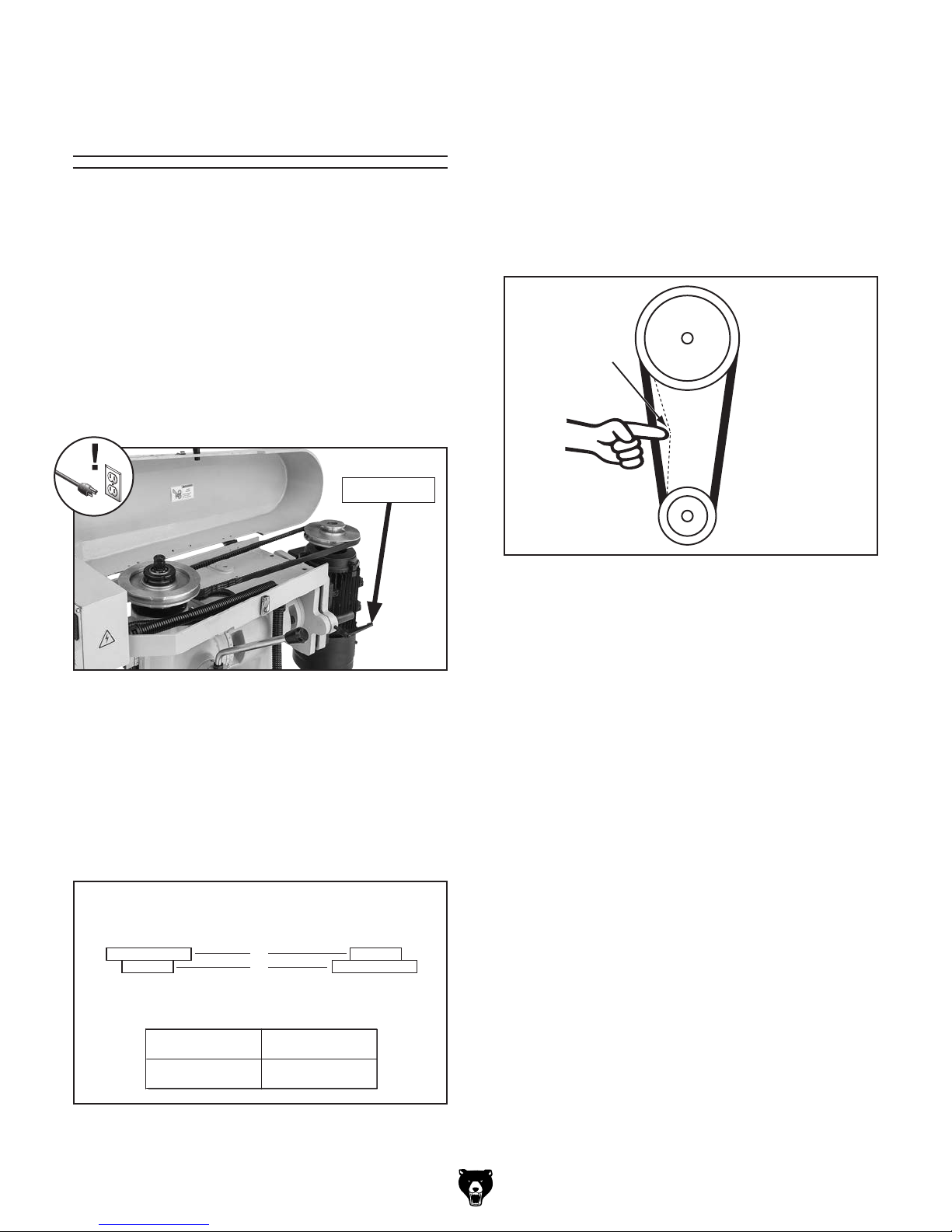
7. Check V-belt tension by applying moderate
pressure on belt with your finger between two
pulleys (see Figure 4). The proper amount
of belt deflection for this machine is approximately
Deflection
½"
1
⁄2".
Pulley
Pulley
Figure 2. V-belt position overview.
4. Press motor toward front of headstock to
release tension on V-belt, then tighten motor
lock to prevent it from re-tensioning belts.
5. Refer to V-belt configuration chart in Figure 3
and position V-belt on appropriate pulleys for
desired spindle speed.
Spindle
Pulley
A
B
Motor
Pulley
SPINDLE R.P.M.
Figure 4. Checking V-belt deflection for proper
tension.
8. Close V-belt cover before beginning
operations.
A B
100–600 425–2500
Figure 3. V-belt configuration chart.
Model G0822 (Mfd. Since 06/17)
-3-
Page 4

MACHINE DATA
SHEET
Customer Service #: (570) 546-9663 · To Order Call: (800) 523-4777 · Fax #: (800) 438-5901
MODEL G0822 VARIABLE‐SPEED MILLING MACHINE WITH
POWER FEED
Product Dimensions:
Weight.............................................................................................................................................................. 810 lbs.
Width (side-to-side) x Depth (front-to-back) x Height........................................................................... 45 x 41 x 68 in.
Footprint (Length x Width)............................................................................................................................ 21 x 28 in.
Space Required for Full Range of Movement (Width x Depth).............................................................. 59 x 39-1/2 in.
Shipping Dimensions:
Type.......................................................................................................................................................... Wood Crate
Content................................................................................................................................................. Machine/Stand
Weight.............................................................................................................................................................. 914 lbs.
Length x Width x Height....................................................................................................................... 40 x 37 x 74 in.
Must Ship Upright................................................................................................................................................... Yes
Electrical:
Power Requirement........................................................................................................... 220V, Single-Phase, 60 Hz
Full-Load Current Rating....................................................................................................................................... 6.4A
Minimum Circuit Size.............................................................................................................................................. 15A
Connection Type....................................................................................................................................... Cord & Plug
Power Cord Included.............................................................................................................................................. Yes
Power Cord Length................................................................................................................................................. 6 ft.
Power Cord Gauge......................................................................................................................................... 14 AWG
Plug Included.......................................................................................................................................................... Yes
Included Plug Type................................................................................................................................................ 6-15
Switch Type.................................................................................................................... ON/OFF Push Button Switch
Inverter (VFD) Type.................................................................................................................................. Delta VFD-E
Inverter (VFD) Size............................................................................................................................................... 2 HP
-4-
Motors:
Main
Horsepower................................................................................................................................................ 2 HP
Phase.................................................................................................................................................... 3-Phase
Amps........................................................................................................................................................... 6.4A
Speed.................................................................................................................................................... Variable
Type........................................................................................................................................... TEFC Induction
Power Transfer ............................................................................................................................... V-Belt Drive
Bearings..................................................................................................... Shielded & Permanently Lubricated
Model G0822 (Mfd. Since 06/17)
Page 5

Main Specifications:
Operation Info
Spindle Travel.............................................................................................................................................. 3 in.
Max Distance Spindle to Column.......................................................................................................... 5-1/4 in.
Max Distance Spindle to Table.................................................................................................................. 11 in.
Longitudinal Table Travel (X-Axis)...................................................................................................... 14-1/4 in.
Longitudinal Leadscrew (X-Axis)............................................................................................................... 36 in.
Cross Table Travel (Y-Axis)......................................................................................................................... 6 in.
Cross Leadscrew (Y-Axis)................................................................................................................... 14-3/4 in.
Vertical Table Travel (Z-Axis).................................................................................................................... 11 in.
Vertical Leadscrew (Z-Axis)....................................................................................................................... 17 in.
Turret or Column Swivel (Left /Right)..................................................................................................... 45 deg.
Head Tilt (Left/Right).............................................................................................................................. 45 deg.
Drilling Capacity for Cast Iron...................................................................................................................... 1 in.
Drilling Capacity for Steel......................................................................................................................... 3/4 in.
End Milling Capacity................................................................................................................................. 3/4 in.
Face Milling Capacity................................................................................................................................... 3 in.
Table Info
Table Length.............................................................................................................................................. 26 in.
Table Width........................................................................................................................................... 6-1/8 in.
Table Thickness.................................................................................................................................... 1-3/4 in.
Table Height (from Floor/Base)........................................................................................................... 17-3/4 in.
Number of T-Slots............................................................................................................................................ 3
T-Slot Size................................................................................................................................................ 1/2 in.
T-Slots Centers...................................................................................................................................... 1-5/8 in.
X-Axis Table Power Feed Rate................................................................................................... 0 – 3-3/8 FPM
X/Y-Axis Travel per Handwheel Revolution.............................................................................................. 0.1 in.
Z-Axis Travel per Handwheel Revolution................................................................................................. 0.1 in.
Spindle Info
Spindle Taper............................................................................................................................................... R-8
Number of Vertical Spindle Speeds...................................................................................................... Variable
Range of Vertical Spindle Speeds........................................... 100 – 600 RPM (Low), 425 – 2500 RPM (High)
Quill Diameter....................................................................................................................................... 2.950 in.
Drawbar Thread Size....................................................................................................................... 7/16-20 TPI
Drawbar Length................................................................................................................................... 11-5/8 in.
Spindle Bearings......................................................................................................... Tapered Roller Bearings
Construction
Spindle Housing/Quill........................................................................................................................... Cast Iron
Table.................................................................................................................................................... Cast Iron
Head.................................................................................................................................................... Cast Iron
Column/Base....................................................................................................................................... Cast Iron
Base..................................................................................................................................................... Cast Iron
Stand.......................................................................................................................................................... Steel
Paint Type/Finish...................................................................................................................................... Epoxy
Other Specifications:
Country of Origin ................................................................................................................................................ China
Warranty ........................................................................................................................................................... 1 Year
Approximate Assembly & Setup Time .............................................................................................................. 1 Hour
Serial Number Location .................................................................................................................................. ID Label
ISO 9001 Factory .................................................................................................................................................. Yes
Certified by a Nationally Recognized Testing Laboratory (NRTL) .......................................................................... No
Model G0822 (Mfd. Since 06/17)
-5-
Page 6

Electrical Cabinet Diagram
Circuit Board
Sensor
Start
DCM
04
FOR/REV
DRO
0
0
1
DCM
SN161209
1
3
1
1
3
4
M2
1
4
3
2
4
3
Stop
E-Stop
Hot
Hot
6-15 Plug
Ground
G
X-Axis Power Feed
GND
Motor 220V
ACM
Potentiometer
10V
AVI
To Motor Fan To Motor
Ground
10V
PE
Ground
L2
N2
DELTA VFD-E
AVI
ACM
DCM
MOTOR MICRO DRIVER
1
L1
N1
1
1
8
L
N
CHINT
Circuit
Breaker
NS2-25
Motor Start
Contactor
Siemens 3TB41 24V
NXB-63
20-25A
CHINT
3
0
L2
L2
N2
N2
2
L1
L1
N1
N1
PE
8
L1
N1
W1
V1
U1
M2
M1
PE
DCM
4
L2
5
4
3
N2
L
2
N
1
DCM
M2
0
M1
PE
PE
JBK5-63
Transformer
HH52PL
5
0
DCM
0
5
L2
L2
5
4
N2
3
N2
2
L
2
N
1
DCM
0
M2
0
M1
PE
PE
PE
-6-
Work Light
Model G0822 (Mfd. Since 06/17)
Page 7

Main
123
132
133
32
131
124
33
125
21
35
33
36
105
32
33
32
130
122
45
34
31
87
121
26
38
31
105
129
126
37
30
9
25
57
84
127
39
29
40
83
125
19
24
16
91
89
88
128
133
41
15
74
66
26
42
21
16
19
65
43
7
11
10
16
14
90
13
77
13
23
63
48
92
26
13
15
13
73
65
60
65
15
20
13
9
106-1
106-3
106-4
102-5
57
87
33
106
102-8
102-9
107
106-2
102-7
108
109
110
79
70
72
98
96
99
97
69
21
72
73
67
7
57
61
62
54
15
55
16
51
114
113
112
113
7
56
74
56
19
56
19
18
112
13
59
19
111
17
35
102-1
111
111
2
100
102-6
82
83
111
102
102-2
84
105
101
103
80
104
81
102-3
102-4
39
31
32
8
7
6
Model G0822 (Mfd. Since 06/17)
5
1
4
3
78
-7-
Page 8

Main Parts List
REF PART # DESCRIPTION REF PART # DESCRIPTION
1 P0822001 BASE 77 P0822077 X-AXIS GIB
2 P0822002 COLUMN 78 P0822078 CABINET BASE
3 P0822003 CAP SCREW M14-2 X 50 79 P0822079 OIL PAN
4 P0822004 LOCK WASHER 14MM 80 P0822080 HEX BOLT M10-1.5 X 45
5 P0822005 FLAT WASHER 14MM 81 P0822081 FLAT WASHER 10MM
6 P0822006 ELEVATION LEADSCREW NUT 82 P0822082 CLUTCH
7 P0822007 CAP SCREW M6-1 X 20 83 P0822083 COMPRESSION SPRING 24 X 15
8 P0822008 ELEVATION LEADSCREW 84 P0822084 SPACER
9 P0822009 MACHINE KEY 6 X 6 X 20 87 P0822087 CAP SCREW M6-1 X 12
10 P0822010 THRUST BEARING 51204 88 P0822088 X-AXIS GRADUATED DIAL (LEFT)
11 P0822011 ELEVATION BEARING BASE 89 P0822089 STEEL BALL 5MM
13 P0822013 BALL BEARING 6004-2RS 90 P0822090 COMPRESSION SPRING 4 X 12
14 P0822014 ELEVATION GEAR 12T 91 P0822091 CAP SCREW M6-1 X 8
15 P0822015 TABBED WASHER 20MM 92 P0822092 CLUTCH
16 P0822016 SPANNER NUT M20-1.5 96 P0822096 MACHINE KEY 5 X 5 X 16
17 P0822017 TABLE BASE CASTING 97 P0822097 CAP SCREW M8-1.25 X 16
18 P0822018 GIB 98 P0822098 LIMIT STOP
19 P0822019 GIB ADJUSTMENT SCREW M6-1 X 38 99 P0822099 LIMIT STOP SLIDE NUT M8-1.25
20 P0822020 CROSS LEADSCREW 100 P0822100 REAR COLUMN COVER
21 P0822021 MACHINE KEY 5 X 5 X 20 101 P0822101 PHLP HD SCR M6-1 X 12
23 P0822023 LEADSCREW BRACKET 102 P0822102 POWER FEED ASSEMBLY AS-235
24 P0822024 THRUST BEARING 51104 102-1 P0822102-1 POWER FEED BODY
25 P0822025 INT THREADED TAPER PIN 8 X 25 102-2 P0822102-2 POWER FEED ADAPTER GEAR
26 P0822026 CAP SCREW M6-1 X 20 102-3 P0822102-3 DETENT SLEEVE
29 P0822029 GRADUATED DIAL 102-4 P0822102-4 COMPRESSION SPRING 1.5 X 17 X 25.5
30 P0822030 KNOB BOLT M5-.8 X 12, KN 102-5 P0822102-5 POWER FEED GRADUATED DIAL
31 P0822031 HANDWHEEL TYPE-8 155D X 16B-S X M10-1.5 102-6 P0822102-6 RETAINING COLLAR
32 P0822032 HANDLE W/O SHAFT 22 X 75, 12 102-7 P0822102-7 LIMIT SWITCH ASONG V52 AN
33 P0822033 SHOULDER SCREW M10-1.5 X 12, 12 X 68 102-8 P0822102-8 LIMIT SWITCH MOUNTING BRACKET
34 P0822034 ELEVATION CRANK 102-9 P0822102-9 PHLP HD SCR M3-.5 X 30
35 P0822035 EXT RETAINING RING 17MM 103 P0822103 FLAT WASHER 6MM
36 P0822036 COMPRESSION SPRING 20 X 20 104 P0822104 LOCK WASHER 10MM
37 P0822037 ELEVATION HANDLE CLUTCH 105 P0822105 SET SCREW M6-1 X 10
38 P0822038 SET SCREW M6-1 X 16 106 P0822106 LED WORKLAMP ASSEMBLY
39 P0822039 ADJUSTMENT NUT 1-1/4 X 20 106-1 P0822106-1 LAMP BODY
40 P0822040 X-AXIS GRADUATED DIAL (RIGHT) 106-2 P0822106-2 BULB LED 24V MR16 1W(3)
41 P0822041 BUSHING 106-3 P0822106-3 LENS COVER
42 P0822042 CAP SCREW M6-1 X 25 106-4 P0822106-4 CAP SCREW M5-.8 X 25
43 P0822043 ADAPTER SLEEVE 107 P0822107 STRAIN RELIEF TYPE-3 M20-1.5
45 P0822045 ELEVATION SHAFT 108 P0822108 POWER CORD 14G 3W 72" 5-15P
48 P0822048 GEAR SHAFT SLEEVE 109 P0822109 MOTOR CORD 14G 5W 48"
51 P0822051 ELEVATION GEAR 12T 110 P0822110 SWITCH CORD 14G 3W 24"
54 P0822054 SPLASH GUARD 111 P0822111 STRAIN RELIEF TYPE-5 M24-1.5
55 P0822055 CROSS LEADSCREW NUT 112 P0822112 BUTTON HD CAP SCR M6-1 X 10
56 P0822056 CAP SCREW M5-.8 X 25 113 P0822113 WAY COVER HOLDER
57 P0822057 FLAT WASHER 6MM 114 P0822114 WAY COVER
59 P0822059 SADDLE 121 P0822121 ONE-SHOT OILER ASSEMBLY
60 P0822060 WAY WIPER (REAR) 122 P0822122 PIPE CONNECTOR M8-1 X 25
61 P0822061 WAY WIPER (FRONT) 123 P0822123 FLAT WASHER 8MM
62 P0822062 CAP SCREW M5-.8 X 12 124 P0822124 OIL DISTRIBUTOR 4-PORT M8-1
63 P0822063 X-AXIS SCALE INDICATOR 125 P0822125 TUBING CONNECTOR M8-1 X 8
65 P0822065 ADJUSTABLE HANDLE M8-1.25 X 35 126 P0822126 OIL DISTRIBUTOR 5-PORT M8-1
66 P0822066 Y-AXIS GIB 127 P0822127 TUBING SHEATH HNL 4-600
67 P0822067 LONGITUDINAL LEADSCREW NUT 128 P0822128 RIGHT-ANGLE FITTING M8-1 X 8
69 P0822069 LONGITUDINAL LEADSCREW 129 P0822129 PIPE JOINT M8-1
70 P0822070 WORK TABLE 130 P0822130 STRAIGHT COUPLING M8-1
72 P0822072 X-AXIS LEADSCREW BRACKET 131 P0822131 TUBING (NYLON)
73 P0822073 CAP SCREW M6-1 X 45 132 P0822132 FLAT WASHER 6MM
74 P0822074 INT THREADED TAPER PIN 8 X 50 133 P0822133 CAP SCREW M6-1 X 20
-8-
Model G0822 (Mfd. Since 06/17)
Page 9

Headstock
292
207
224
225
244
245
246
248
252
247
248
249
250
251
253 254
255
228
262
294
297
226
263
256
298
227
242
261
293
296
243
257
223
295
206
284
229
220
258
211
222
214
213
212
302
219
218
217
216
215
201
221
288
286
285
266
291
202
269
260
259
287
289
210
209
203
283
282
230
267
231
290
232
291
268
271
270
234
235
204
272
273
274
238
233
236
281
278
240 241
237
205-1
205-3
205-2
205
275
239
205-3
280
279
277
276
264
Model G0822 (Mfd. Since 06/17)
264
265
208
299
301
300
-9-
Page 10

Headstock Parts List
REF PART # DESCRIPTION REF PART # DESCRIPTION
201 P0822201 SPINDLE HEAD 251 P0822251 HANDWHEEL TYPE-21 115D X 12B-K X M18-2.5
202 P0822202 ROCKER ARM BRIDGE 252 P0822252 SET SCREW M5-.8 X 16
203 P0822203 MOTOR BRACKET 253 P0822253 HANDLE W/O SHAFT 18 X 65, 8
204 P0822204 MOTOR MOUNTING PLATE 254 P0822254 HANDLE 58L, M6-1 X 10, 10 OD
205 P0822205 MOTOR 2 HP 220V 3-PH 255 P0822255 QUILL LOCK SCREW M8-1.25 X 125
205-1 P0822205-1 MOTOR FAN COVER 256 P0822256 LOCK SET (OUTER)
205-2 P0822205-2 MOTOR FAN 257 P0822257 SPACER
205-3 P0822205-3 BALL BEARING 6205ZZ 258 P0822258 LOCK SET (INNER)
206 P0822206 BELT HOUSING BASE 259 P0822259 SET SCREW M6-1 X 8 CONE-PT
207 P0822207 BELT HOUSING COVER 260 P0822260 SET SCREW M6-1 X 8
208 P0822208 SPINDLE R8 261 P0822261 QUILL DOG
209 P0822209 BEARING COVER 262 P0822262 SET SCREW M6-1 X 10
210 P0822210 TAPERED ROLLER BEARING 30207 263 P0822263 COMPRESSION SPRING 11 X 48
211 P0822211 SPINDLE SLEEVE 264 P0822264 DEPTH STOP LIMIT NUT M12-1
212 P0822212 TAPERED ROLLER BEARING 30206 265 P0822265 LEADSCREW
213 P0822213 TABBED WASHER 30MM 266 P0822266 T-BOLT M10-1.5 X 40
214 P0822214 SPANNER NUT M30-1.5 267 P0822267 FLAT WASHER 10MM
215 P0822215 INT RETAINING RING 75MM 268 P0822268 HEX NUT M10-1.5
216 P0822216 BALL BEARING 6009ZZ 269 P0822269 T-BOLT M10-1.5 X 40
217 P0822217 BALL BEARING 6009ZZ 270 P0822270 FLAT WASHER 10MM
218 P0822218 SPINDLE COVER 271 P0822271 HEX NUT M10-1.5
219 P0822219 PHLP HD SCR M5-.8 X 12 272 P0822272 T-BOLT M10-1.5 X 40
220 P0822220 SHAFT 273 P0822273 FLAT WASHER 10MM
221 P0822221 SPINDLE PULLEY 274 P0822274 HEX NUT M10-1.5
222 P0822222 SPANNER NUT M42 X 1.5 275 P0822275 DOWEL PIN 14 X 55
223 P0822223 SPANNER NUT M42 X 1.5 276 P0822276 COMPRESSION SPRING 11 X 48
224 P0822224 SPINDLE RETURN NUT M18-1.5 277 P0822277 BUSHING
225 P0822225 SET SCREW M6-1 X 10 278 P0822278 ADJUSTABLE HANDLE M8-1.25 X 25
226 P0822226 RETURN SPRING COVER (LEFT) 279 P0822279 FLAT WASHER 8MM
227 P0822227 CLUTCH 280 P0822280 HEX BOLT M8-1.25 X 20
228 P0822228 COMPRESSION SPRING 25 X 33 281 P0822281 MACHINE KEY 8 X 8 X 35
229 P0822229 GEAR 48T 282 P0822282 STUD-SE M12-1.75 X 155, 12
230 P0822230 MACHINE KEY 6 X 6 X 15 283 P0822283 HEX NUT M12-1.75
231 P0822231 GEAR SHAFT 284 P0822284 RETAINING RING
232 P0822232 TORSION SPRING 32 X 80 285 P0822285 MAGNETIC BEAD
233 P0822233 RETURN SPRING COVER (RIGHT) 286 P0822286 SENSOR BRACKET
234 P0822234 OIL CUP 8MM 287 P0822287 SENSOR
235 P0822235 CAP SCREW M5-.8 X 20 288 P0822288 CAP SCREW M4-.7 X 16
236 P0822236 EXT RETAINING RING 19MM 289 P0822289 HEX BOLT M6-1 X 35
237 P0822237 HANDLE HUB 290 P0822290 MOTOR PULLEY
238 P0822238 CAP SCREW M8-1.25 X 25 291 P0822291 SET SCREW M8-1.25 X 10
239 P0822239 HEX NUT M10-1.5 292 P0822292 V-BELT V13 X 1395
240 P0822240 HANDLE SHAFT M10-1.5 X 240 293 P0822293 BELT HOUSING HINGE
241 P0822241 HANDLE M10-1.5 X 24 X 32 (PLASTIC) 294 P0822294 CAP SCREW M6-1 X 12
242 P0822242 GEAR SHAFT 295 P0822295 CAP SCREW M6-1 X 12
243 P0822243 MACHINE KEY 4 X 4 X 20 296 P0822296 COVER HINGE 40 X 40
244 P0822244 THRUST BEARING 51102 297 P0822297 FLAT HD SCR M5-.8 X 12
245 P0822245 SHAFT SLEEVE 298 P0822298 CONTROL PANEL ASSEMBLY
246 P0822246 CAP SCREW 299 P0822299 SET SCREW M5-.8 X 6
247 P0822247 THRUST BEARING 51102 300 P0822300 SET SCREW M5-.8 X 6
248 P0822248 HEX NUT M14-1.5 THIN 301 P0822301 DRAWBAR 7/16-20
249 P0822249 GRADUATED DIAL 302 P0822302 SEAL
250 P0822250 KNOB BOLT M5-.8 X 12 KN
-10 -
Model G0822 (Mfd. Since 06/17)
Page 11

Electrical Components & Accessories
Electrical Components
3/L2
20
OFF
Test
401
5/L3
ON
QF1
CHINT
NXB-83
C2
402
A1
1L1
3L2 5L3
13NO 21NC
KA Contactor
Siemens 3TB41 24V
22E
14NO 22NC 32NC 44NO
2T1 4T2 6T3
403
1/L1
21 22 13 14
25
23
20-25A
NS2-25
CHINT
2/T1 4/T2 6/T3
405
406
429
434
433
427
432
31NC 43NO
407
A2
E&E HH52P-L
24V %A
MOTOR MICRO DRIVER
DELTA VFD-E
MI2
MI4
MI6
MI1
MI3
MI5
U
T1
GND
PE 0 220 230 380 400
KA
430
S
R
L2
L1
DCM
DCM
24V
DCM
VT2W
T3
Transformer
426
T
L3
AFM
MCM
ACI
ACM
AVI
ACM
AVI
B1+B2
JBK5-40VA
0 24
435
MO1
10V
10V
404
RB
RCRA
GND
428
TC
408
416
418
419
420
409
Potentiometer
421
424
Control Panel
DRO
FOR/REV Switch
1
NC
2
E-Stop
2
1NC
412
Sensor Circuit Board
425
2
NC
1
413
417
422
410
415
431
Start Button
Stop Button
2
414
423
411
1NC
REF PART # DESCRIPTION REF PART # DESCRIPTION
401 P0822401 ON/OFF SWITCH CHINT NS2-25 20-25A 419 P0822419 HEX WRENCH 5MM
402 P0822402 CIRCUIT BREAKER CHINT NXB-83 C2 420 P0822420 HEX WRENCH 4MM
403 P0822403 CONTACTOR SIEMENS 3TB41 24V 421 P0822421 HEX WRENCH 3MM
404 P0822404 MICRO VFD DELTA VFD-E 422 P0822422 WRENCH 12 X 14MM OPEN-ENDS
405 P0822405 TERMINAL BAR 1P 423 P0822423 WRENCH 17 X 19MM OPEN-ENDS
406 P0822406 TERMINAL BAR (GROUNDING) 1P 424 P0822424 SCREWDRIVER FLAT #2
407 P0822407 RELAY E & E HH52P-L 24V 5A 425 P0822425 SCREWDRIVER PHILLIPS #2
408 P0822408 TRANSFORMER BEJING AOHENGA JBK5-40VA 426 P0822426 ADAPTER MT#3-MT#2
409 P0822409 SPINDLE DIGITAL READOUT SN161209 427 P0822427 DRILL CHUCK ARBOR R8-B16
410 P0822410 FOR/REV SWITCH 428 P0822428 SPINDLE SLEEVE R8-MT#3
411 P0822411 ON BUTTON 429 P0822429 CHUCK KEY
412 P0822412 POTENTIOMETER 430 P0822430 DRILL CHUCK B16 1-13MM
413 P0822413 E-STOP BUTTON 431 P0822431 BOTTLE FOR OIL
414 P0822414 OFF BUTTON 432 P0822432 T-BOLT M12-1.75 X 55
415 P0822415 SENSOR CIRCUIT BOARD 433 P0822433 FLAT WASHER 12MM
416 P0822416 ELECTRICAL BOX 434 P0822434 HEX NUT M12-1.75
417 P0822417 TOOLBOX 435 P0822435 DRIFT KEY
418 P0822418 HEX WRENCH 6MM
Model G0822 (Mfd. Since 06/17)
-11-
Page 12

G0822 Machine Labels B
(11/09/16)
• Label is actual size
• Label must be made of
oil-resistant material
***These labels must have individual letters/numbers. Do not print with clear background.
grizzly.com
***
G0822
***
To reduce risk of death
or serious injury, read
manual BEFORE using
machine.
To get a new manual, call
(800) 523-4777 or go to
www.grizzly.com.
WARNING!
K
CO
H
S
/Y
RU
J
NI
!D
RAZA
H
rew
op
tc
e
n
noc
s
iD
,
s
tne
m
tsu
jda
e
r
o
feb
ro
,ec
nan
e
t
n
iam
.
e
c
ivr
es
Always keep this
cover closed
during operation.
PINCH
HAZARD!
WARNING!
COLOR CODES
GRIZZLY BEIGE
PANTONE 7527 C
WARNING!
ENTANGLEMENT
HAZARD!
Tie back long hair, roll up
long sleeves, and remove
loose clothing, jewelry, or
gloves to prevent getting
caught in moving parts.
Always wear
ANSI-approved safety
glasses and face shield
when using this
machine.
EYE/FACE INJURY
HAZARD!
G0822 Machine Labels B
(11/09/16)
• Label is actual size
• Label must be made of
oil-resistant material
***These labels must have individual letters/numbers. Do not print with clear background.
grizzly.com
***
To reduce risk of death
or serious injury, read
manual BEFORE using
machine.
To get a new manual, call
(800) 523-4777 or go to
www.grizzly.com.
WARNING!
K
C
OHS/
YRU
J
N
I
!D
RAZ
AH
r
e
wop t
c
e
n
n
oc
si
D
,s
t
n
emts
uj
d
a
er
o
f
e
b
r
o ,
e
cn
a
netn
ia
m
.
e
c
i
v
res
Always keep this
cover closed
during operation.
PINCH
HAZARD!
WARNING!
COLOR CODES
GRIZZLY BEIGE
PANTONE 7527 C
WARNING!
ENTANGLEMENT
HAZARD!
Tie back long hair, roll up
long sleeves, and remove
loose clothing, jewelry, or
gloves to prevent getting
caught in moving parts.
Always wear
ANSI-approved safety
glasses and face shield
when using this
machine.
EYE/FACE INJURY
HAZARD!
(11/09/16)
• Label is actual size
• Label must be made of
oil-resistant material
(11/09/16)
• Scale = 1:1
(unless otherwise noted)
• Labels MUST be made of
chemical-resistant material
• Lubricant: Use Grizzly T23962
Machine Oil or ISO 68 equivalent.
• To operate pump, pull handle six
times every 4 hours of use.
COLOR CODES
GRIZZLY LOGO RED
PANTONE 711C or RAL 3020
PANTONE 151 C or RAL 2005
WARNING
NOTICE
PANTONE 3005 C or RAL 5005
(11/09/16)
• Label is actual size
• Label must be made of
oil-resistant material
To reduce risk of death
or serious injury, read
manual BEFORE using
machine.
To get a new manual, call
(800) 523-4777 or go to
www.grizzly.com.
WARNING!
(11/09/16)
• Label is actual size
• Label must be made of
oil-resistant material
To reduce risk of death
or serious injury, read
manual BEFORE using
machine.
To get a new manual, call
(800) 523-4777 or go to
www.grizzly.com.
WARNING!
INJURY/SHOCK
HAZARD!
Disconnect power
before adjustments,
maintenance, or
service.
Always keep this
cover closed
during operation.
PINCH
HAZARD!
WARNING!
WARNING!
ENTANGLEMENT
HAZARD!
Tie back long hair, roll up
long sleeves, and remove
loose clothing, jewelry, or
gloves to prevent getting
caught in moving parts.
(11/09/16)
• Label is actual size
• Label must be made of
oil-resistant material
To reduce risk of death
or serious injury, read
manual BEFORE using
machine.
To get a new manual, call
(800) 523-4777 or go to
www.grizzly.com.
WARNING!
WARNING!
ENTANGLEMENT
HAZARD!
Tie back long hair, roll up
long sleeves, and remove
loose clothing, jewelry, or
gloves to prevent getting
caught in moving parts.
• Label is actual size
• Label must be made of
oil-resistant material
COLOR CODES
GRIZZLY LOGO RED
PANTONE 711C or RAL 3020
PANTONE 151 C or RAL 2005
WARNING
NOTICE
PANTONE 3005 C or RAL 5005
• Label is actual size
• Label must be made of
oil-resistant material
501
WARNING!
To reduce risk of death
or serious injury, read
manual BEFORE using
machine.
To get a new manual, call
(800) 523-4777 or go to
www.grizzly.com.
502
Labels
503 504
WARNING!
ENTANGLEMENT
HAZARD!
Tie back long hair, roll up
long sleeves, and remove
loose clothing, jewelry, or
gloves to prevent getting
caught in moving parts.
EYE/FACE INJURY
HAZARD!
Always wear
ANSI-approved safety
glasses and face shield
when using this
machine.
505
INJURY/SHOCK
HAZARD!
Disconnect power
before adjustments,
maintenance, or
service.
506
WARNING!
PINCH
HAZARD!
Always keep this
cover closed
during operation.
502
• Lubricant: Use Grizzly T23962
Machine Oil or ISO 68 equivalent.
• To operate pump, pull handle six
times every 4 hours of use.
511
512
510
508
509
507
MODEL G0822
VS MILLING MACHINE
w/POWER FEED
Specifications
Power Requirement: 220V, 1-Ph, 15A, 60 Hz
Motor: 2 HP, 220V, 3-Ph, 6.4A
Max. Distance Spindle-to-Column: 5-1/4"
Max. Distance Spindle-to-Table: 11"
Spindle Travel: 3"
Spindle Taper: R-8
Drawbar Thread Size: 7/16"-20
Spindle Speeds: (Variable) 100–2500 RPM
Longitudinal Table Travel: 14-1/4"
Cross Table Travel: 6"
Vertical Table Travel: 11"
Head Tilt: 45° Left/Right
Turret Swivel: 45° Left/Right
Weight: 810 lbs.
To reduce the risk of serious personal injury while using this machine:
1. Read and understand owner’s manual before starting.
2. Always wear approved safety glasses AND a face shield.
3. Only plug power cord into a grounded outlet.
4. Disconnect power before setting up, adjusting, or servicing.
5. Tie back long hair, roll up sleeves, and DO NOT wear loose
clothing, gloves, or jewelry.
6. Keep all guards in place and covers closed during operation.
7. Never use hands to secure workpiece to table during
operation—use clamps or a vise.
8. Avoid positioning hands where they could slip into rotating bits.
9. Never attempt to slow or stop spindle with hands or tools.
10. Always use proper feeds and speeds for operation and workpiece.
11. Never leave machine running unattended.
12. DO NOT expose to rain or use in wet locations.
13. Prevent unauthorized use by children or untrained users.
Mfd. for Grizzly in China
Date
S/N
502
REF PART # DESCRIPTION REF PART # DESCRIPTION
501 P0822501 READ MANUAL LABEL 507 P0822507 MACHINE ID LABEL
502 P0822502 ELECTRICITY LABEL 508 P0822508 TOUCH-UP PAINT, GRIZZLY GREEN
503 P0822503 ENTANGLEMENT HAZARD LABEL 509 P0822509 GRIZZLY.COM LABEL
504 P0822504 EYE/FACE INJURY HAZARD LABEL 510 P0822510 MODEL NUMBER LABEL
505 P0822505 DISCONNECT POWER LABEL 511 P0822511 LUBRICATION NOTICE
506 P0822506 PINCH HAZARD LABEL 512 P0822512 TOUCH-UP PAINT, GRIZZLY BEIGE
-12-
Model G0822 (Mfd. Since 06/17)
 Loading...