

Page 1

MODEL G0813/G0814
6" JOINTER
OWNER'S MANUAL
(For models manufactured since 03/16)
COPYRIGHT © MARCH, 2016 BY GRIZZLY INDUSTRIAL, INC. REVISED SEPTEMBER, 2016 (BL)
WARNING: NO PORTION OF THIS MANUAL MAY BE REPRODUCED IN ANY SHAPE
OR FORM WITHOUT THE WRITTEN APPROVAL OF GRIZZLY INDUSTRIAL, INC.
#BL18046 PRINTED IN TAIWA N
V1.09.16
Page 2

This manual provides critical safety instructions on the proper setup,
operation, maintenance, and service of this machine/tool. Save this
document, refer to it often, and use it to instruct other operators.
Failure to read, understand and follow the instructions in this manual
may result in fire or serious personal injury—including amputation,
electrocution, or death.
The owner of this machine/tool is solely responsible for its safe use.
This responsibility includes but is not limited to proper installation in
a safe environment, personnel training and usage authorization,
proper inspection and maintenance, manual availability and comprehension, application of safety devices, cutting/sanding/grinding tool
integrity, and the usage of personal protective equipment.
The manufacturer will not be held liable for injury or property damage
from negligence, improper training, machine modifications or misuse.
Some dust created by power sanding, sawing, grinding, drilling, and
other construction activities contains chemicals known to the State
of California to cause cancer, birth defects or other reproductive
harm. Some examples of these chemicals are:
• Lead from lead-based paints.
• Crystalline silica from bricks, cement and other masonry products.
• Arsenic and chromium from chemically-treated lumber.
Your risk from these exposures varies, depending on how often you
do this type of work. To reduce your exposure to these chemicals:
Work in a well ventilated area, and work with approved safety equipment, such as those dust masks that are specially designed to filter
out microscopic particles.
Page 3

Table of Contents
INTRODUCTION ............................................... 2
Contact Info.................................................... 2
Machine Differences ...................................... 2
Manual Accuracy ........................................... 2
Identification ................................................... 3
Controls & Components ................................. 4
G0813 Machine Data Sheet .......................... 6
G0814 Machine Data Sheet .......................... 8
SECTION 1: SAFETY ..................................... 10
Safety Instructions for Machinery ................ 10
Additional Safety for Jointers ....................... 12
SECTION 2: POWER SUPPLY ...................... 13
Voltage Conversion to 220V ........................ 15
SECTION 3: SETUP ....................................... 16
Needed for Setup ......................................... 16
Unpacking .................................................... 16
Hardware Recognition Chart ....................... 17
G0813 Inventory .......................................... 18
G0814 Inventory .......................................... 19
Cleanup ........................................................ 20
Site Considerations ...................................... 21
Assembly ..................................................... 22
Dust Collection ............................................. 29
Test Run ...................................................... 29
Recommended Adjustments ........................ 30
SECTION 4: OPERATIONS ........................... 31
Operation Overview ..................................... 31
Stock Inspection & Requirements................ 32
Setting Depth of Cut .................................... 33
Squaring Stock............................................. 34
Surface Planing............................................ 35
Edge Jointing ............................................... 36
Bevel Cutting................................................ 37
Rabbet Cutting ............................................. 38
SECTION 6: MAINTENANCE ......................... 41
Schedule ...................................................... 41
Cleaning & Protecting .................................. 41
Lubrication ................................................... 42
SECTION 7: SERVICE ................................... 43
Troubleshooting ........................................... 43
Inspecting Knives ......................................... 45
Setting/Replacing Knives ............................. 45
Setting Outfeed Table Height ...................... 48
Calibrating Depth Scale ............................... 49
Adjusting Gibs .............................................. 49
Setting Fence Stops .................................... 50
Replacing/Tensioning Belt ........................... 51
Aligning Pulleys............................................ 52
Checking/Adjusting Table Parallelism ......... 53
SECTION 8: WIRING ...................................... 54
Wiring Safety Instructions ............................ 54
110V Wiring Diagram ................................... 55
220V Wiring Diagram ................................... 56
SECTION 9: PARTS ....................................... 57
Table ............................................................ 57
Fence ........................................................... 59
Cutterhead .................................................. 60
G0813 Stand ................................................ 61
G0814 Stand ................................................ 63
G0813 Labels & Cosmetics ......................... 65
G0814 Labels & Cosmetics ......................... 66
WARRANTY & RETURNS ............................. 69
SECTION 5: ACCESSORIES ......................... 39
Page 4

We stand behind our machines! If you have questions or need help, contact us with the information
below. Before contacting, make sure you get the
serial number
machine ID label. This will help us help you faster.
We want your feedback on this manual. What did
you like about it? Where could it be improved?
Please take a few minutes to give us feedback.
Email: manuals@grizzly.com
We are proud to provide a high-quality owner’s
manual with your new machine!
We
instructions, specifications, drawings, and photographs
in this manual. Sometimes we make mistakes, but
our policy of continuous improvement also means
that
you receive is
slightly different than shown in the manual
If you find this to be the case, and the difference
between the manual and machine leaves you
confused or unsure about something
check our
website for an updated version. W
current
manuals and
on our web-
site at
Alternatively, you can call our Technical Support
for help. Before calling, make sure you write down
the
from
the machine ID label (see below). This information
is required for us to provide proper tech support,
and it helps us determine if updated documentation is available for your machine.
INTRODUCTION
Contact Info
and manufacture date from the
Grizzly Technical Support
1815 W. Battlefield
Springfield, MO 65807
Phone: (570) 546-9663
Email: techsupport@grizzly.com
Grizzly Documentation Manager
P.O. Box 2069
Bellingham, WA 98227-2069
Manual Accuracy
made every effort to be exact with the
sometimes the machine
.
,
e post
manual updates for free
www.grizzly.com.
Manufacture Date and Serial Number
Machine Differences
Models G0813 and G0814 are the same machines
in all respects except for the following: the Model
G0813 knock-down stand requires assembly; the
Model G0814 one-piece cabinet stand requires no
assembly.
Manufacture Date
Serial Number
-2-
Model G0813/G0814 (Mfd. Since 3/16)
Page 5
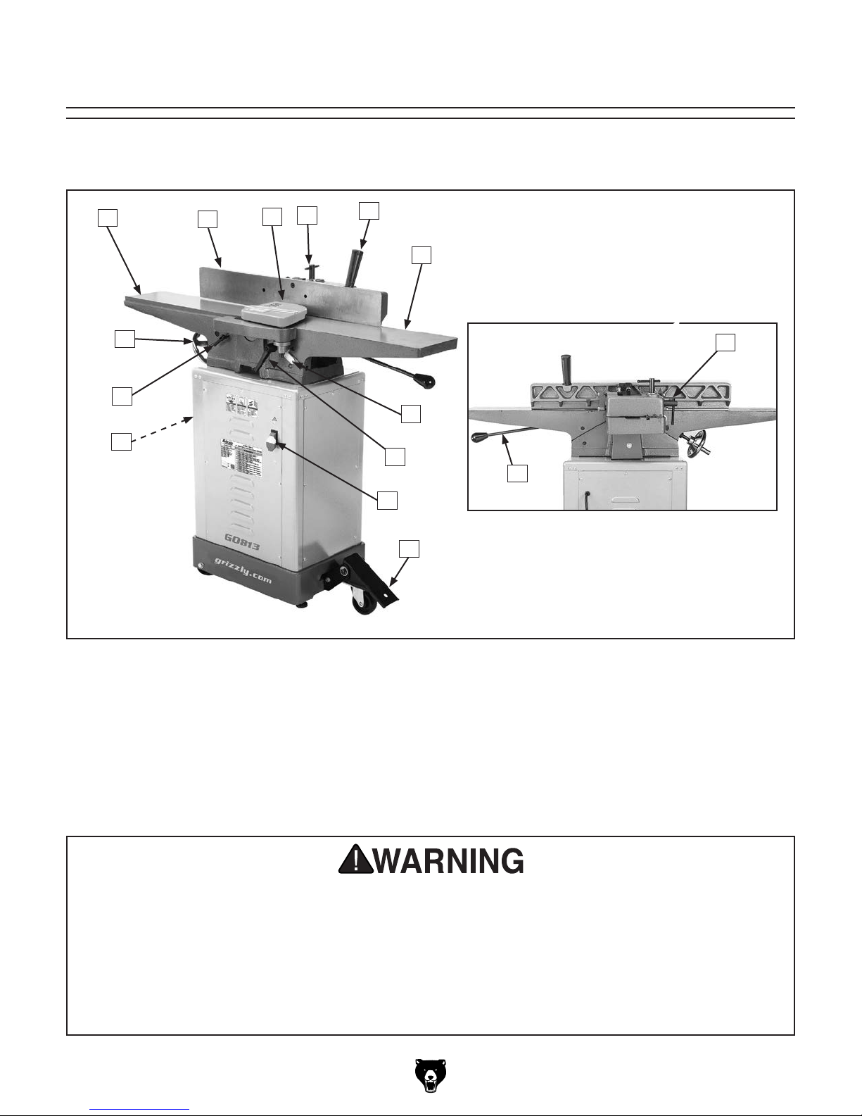
Identification
Become familiar with the names and locations of the controls and features shown below to better understand
the instructions in this manual.
D
A
O
N
M
B
C
E
F
H
I
J
G
K
L
A. Outfeed Table
B. Fence
C. Cutterhead Guard
D. Fence Lock
E. Fence Tilt Handle
F. Infeed Table
G. Infeed Table Lever
H. Fence Tilt Lock
I. Depth Scale
J. Infeed Table Lock
K. ON/OFF Paddle Switch w/Disabling Key
L. Foot Pedal Caster Assembly
M. Dust Port
N. Outfeed Table Lock
O. Outfeed Table Handwheel
For Your Own Safety Read Instruction Manual Before Operating Jointer
a) Wear eye protection.
b) Always keep cutterhead and drive guards in place and in proper operating condition. ALWAYS
replace cutterhead guard after rabbeting operations.
c) Never make jointing or rabbeting cuts deeper than
d) Always use hold-down or push blocks when jointing material narrower than 3" or surface
planing material thinner than 3".
e) Never perform jointing, planing, or rabbeting cuts on pieces shorter than 8" in length.
Model G0813/G0814 (Mfd. Since 3/16)
1
⁄8" or planing cuts deeper than 1⁄16".
-3-
Page 6

Controls &
To reduce your risk of
serious injury, read this
entire manual BEFORE
B
C
Components
using machine.
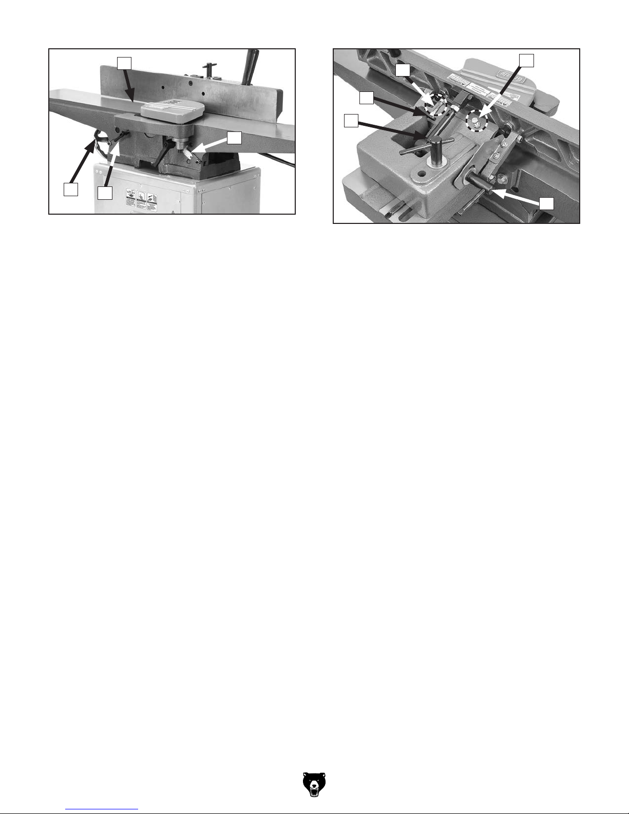
Refer to Figures 1–4 and the following descriptions to become familiar with the basic controls
and components of this machine. Understanding
these items and how they work will help you
understand the rest of the manual and stay safe
when operating this machine.
A
D
G
J
Figure 2. Main table controls, fence, and foot
pedal caster.
B. Fence: Guides workpiece as it moves across
cutterhead; determines angle of cut.
C. Fence Tilt Handle: Tilts fence throughout its
range of motion from 45° inward to 45° outward (135°).
D. Infeed Table: Supports workpiece before it
reaches cutterhead. Position of infeed table
relative to cutterhead determines depth of
cut.
E
Figure 1. ON/OFF paddle switch location.
A. ON/OFF Paddle Switch w/Disabling Key:
Turns motor ON and OFF. Remove yellow
key to disable switch.
E. Infeed Table Adjustment Lever: Adjusts
position of infeed table (when infeed table
lock is loosened).
J. Infeed Table Lock: Loosens to allow adjust-
ment of infeed table height or cutting depth
tightens to secure infeed table.
G. Outfeed Table: Supports workpiece after
it passes over cutterhead. For safety and
best results, outfeed table must be properly
adjusted relative to cutterhead knives before
ANY operations (refer to Page 48 for more
details).
-4-
Model G0813/G0814 (Mfd. Since 3/16)
Page 7
H
N
O
M
L
I
F
K
Figure 3. Cutterhead guard and depth-of-cut
scale.
H. Cutterhead Guard: Covers cutterhead
until pushed out of the way by workpiece
during operation. When workpiece leaves
cutterhead, guard springs back to its starting
position.
I. Depth-of-Cut Scale: Indicates cutting depth
of a single pass.
F. Outfeed Table Handwheel: Adjusts position
of outfeed table. Typically only used when
setting outfeed table even with cutterhead
knives or when servicing the cutterhead.
K. Outfeed Table Lock: Loosens to allow
adjustment of outfeed table height; tightens
to secure outfeed table.
P
Figure 4. Fence controls.
L. Fence Lock: Loosens to allow adjustment of
fence position along width of tables. Tightens
to secure fence.
M. Swing Stop: When engaged, stops fence
at 90°. When disengaged, allows fence to
adjust for bevel cuts.
N. 90° Fence Stop: When engaged, stops
fence at 90°.
Note: Even when fence stop bolt contacts
swing stop, tilt lock must be tightened before
starting machine.
Note: Swing stop must be disengaged for
bevel cuts greater than 90°.
Model G0813/G0814 (Mfd. Since 3/16)
O. 45° Fence Stop: Stops fence at 45° outward
(135°).
Note: Even when fence is resting against
stops, tilt lock must be tightened before starting machine.
P. Fence Tilt Lock: Secures fence tilt setting at
desired angle.
-5-
Page 8

MACHINE DATA
SHEET
Customer Service #: (570) 546-9663 · To Order Call: (800) 523-4777 · Fax #: (800) 438-5901
MODEL G0813 6" JOINTER WITH KNOCK‐DOWN STAND
Product Dimensions:
Weight.............................................................................................................................................................. 247 lbs.
Width (side-to-side) x Depth (front-to-back) x Height..................................................................... 47-1/2 x 20 x 42 in.
Footprint (Length x Width)..................................................................................................................... 14-1/4 x 27 in.
Shipping Dimensions:
Carton #1
Type........................................................................................................................................... Cardboard Box
Content................................................................................................................................................. Machine
Weight.................................................................................................................................................... 239 lbs.
Length x Width x Height............................................................................................................. 49 x 22 x 13 in.
Must Ship Upright......................................................................................................................................... Yes
Carton #2
Type........................................................................................................................................... Cardboard Box
Content...................................................................................................................................................... Stand
Weight...................................................................................................................................................... 13 lbs.
Length x Width x Height............................................................................................................... 16 x 19 x 6 in.
Must Ship Upright.......................................................................................................................................... No
Electrical:
Power Requirement............................................................................................. 110V or 220V, Single-Phase, 60 Hz
Prewired Voltage.................................................................................................................................................. 110V
Full-Load Current Rating........................................................................................................................................ 14A
Minimum Circuit Size.............................................................................................................................................. 20A
Connection Type....................................................................................................................................... Cord & Plug
Power Cord Included.............................................................................................................................................. Yes
Power Cord Length................................................................................................................................................. 6 ft.
Power Cord Gauge......................................................................................................................................... 16 AWG
Plug Included.......................................................................................................................................................... Yes
Included Plug Type................................................................................................................................................ 5-15
Switch Type.................................................................................................. Paddle Safety Switch w/Removable Key
Motors:
Main
Type................................................................................................................. TEFC Capacitor-Start Induction
Horsepower................................................................................................................................................ 1 HP
Phase............................................................................................................................................ Single-Phase
Amps....................................................................................................................................................... 14A/7A
Speed................................................................................................................................................ 3450 RPM
Power Transfer .................................................................................................................................. Belt Drive
Bearings........................................................................................................ Sealed & Permanently Lubricated
-6-
Model G0813/G0814 (Mfd. Since 3/16)
Page 9

Main Specifications:
Main Specifications
Jointer Size.................................................................................................................................................. 6 in.
Bevel Jointing............................................................................................................................. 0 – 45 deg. L/R
Maximum Width of Cut................................................................................................................................ 6 in.
Maximum Depth of Cut............................................................................................................................. 1/8 in.
Minimum Workpiece Length........................................................................................................................ 4 in.
Minimum Workpiece Thickness................................................................................................................ 1/2 in.
Maximum Rabbeting Depth...................................................................................................................... 1/2 in.
Number of Cuts Per Minute..................................................................................................................... 15,000
Fence Information
Fence Length....................................................................................................................................... 29-1/8 in.
Fence Width.......................................................................................................................................... 1-1/4 in.
Fence Height............................................................................................................................................... 4 in.
Fence Stops............................................................................................................................. 45, 90, 135 deg.
Cutterhead Information
Cutterhead Type........................................................................................................................... Straight Knife
Cutterhead Diameter............................................................................................................................. 2-1/2 in.
Cutterhead Speed............................................................................................................................. 5000 RPM
Knife Information
Number of Knives............................................................................................................................................. 3
Knife Length................................................................................................................................................. 6 in.
Knife Width.................................................................................................................................................. 1 in.
Knife Thickness........................................................................................................................................ 1/8 in.
Knife Adjustment............................................................................................................................ Jack Screws
Table Information
Table Length........................................................................................................................................ 47-3/8 in.
Table Width........................................................................................................................................... 6-5/8 in.
Table Thickness.................................................................................................................................... 1-1/4 in.
Floor to Table Height........................................................................................................................... 33-5/8 in.
Table Adjustment Type........................................................................................................... Handwheel/Lever
Table Movement Type............................................................................................................. Dovetailed Ways
Construction
Base........................................................................................................................................................... Steel
Body Assembly.................................................................................................................................... Cast Iron
Fence Assembly.................................................................................................................................. Cast Iron
Guard.......................................................................................................................................... Die Cast Metal
Table....................................................................................................................... Precision-Ground Cast Iron
Paint Type/Finish....................................................................................................................... Powder Coated
Other Information
Number of Dust Ports....................................................................................................................................... 1
Dust Port Size.............................................................................................................................................. 4 in.
Mobile Base............................................................................................................................................. Built-In
Other Specifications:
Country of Origin .............................................................................................................................................. Taiwan
Warranty ........................................................................................................................................................... 1 Year
Approximate Assembly & Setup Time .............................................................................................................. 1 Hour
Serial Number Location .................................................................................................................................. ID Label
ISO 9001 Factory .................................................................................................................................................... No
Certified by a Nationally Recognized Testing Laboratory (NRTL) .......................................................................... No
Model G0813/G0814 (Mfd. Since 3/16)
-7-
Page 10

MACHINE DATA
SHEET
Customer Service #: (570) 546-9663 · To Order Call: (800) 523-4777 · Fax #: (800) 438-5901
MODEL G0814 6" JOINTER WITH CABINET STAND
Product Dimensions:
Weight.............................................................................................................................................................. 245 lbs.
Width (side-to-side) x Depth (front-to-back) x Height..................................................................... 47-1/2 x 20 x 42 in.
Footprint (Length x Width)..................................................................................................................... 13-1/2 x 18 in.
Shipping Dimensions:
Carton #1
Type........................................................................................................................................... Cardboard Box
Content................................................................................................................................................. Machine
Weight.................................................................................................................................................... 183 lbs.
Length x Width x Height............................................................................................................. 49 x 22 x 13 in.
Must Ship Upright......................................................................................................................................... Yes
Carton #2
Type........................................................................................................................................... Cardboard Box
Content...................................................................................................................................................... Stand
Weight...................................................................................................................................................... 77 lbs.
Length x Width x Height............................................................................................................. 21 x 17 x 30 in.
Must Ship Upright.......................................................................................................................................... No
Electrical:
Power Requirement............................................................................................. 110V or 220V, Single-Phase, 60 Hz
Prewired Voltage.................................................................................................................................................. 110V
Full-Load Current Rating........................................................................................................................................ 14A
Minimum Circuit Size.............................................................................................................................................. 20A
Connection Type....................................................................................................................................... Cord & Plug
Power Cord Included.............................................................................................................................................. Yes
Power Cord Length................................................................................................................................................. 6 ft.
Power Cord Gauge......................................................................................................................................... 16 AWG
Plug Included.......................................................................................................................................................... Yes
Included Plug Type................................................................................................................................................ 5-15
Switch Type.................................................................................................. Paddle Safety Switch w/Removable Key
Motors:
Main
Type................................................................................................................. TEFC Capacitor-Start Induction
Horsepower................................................................................................................................................ 1 HP
Phase............................................................................................................................................ Single-Phase
Amps....................................................................................................................................................... 14A/7A
Speed................................................................................................................................................ 3450 RPM
Power Transfer .................................................................................................................................. Belt Drive
Bearings........................................................................................................ Sealed & Permanently Lubricated
-8-
Model G0813/G0814 (Mfd. Since 3/16)
Page 11

Main Specifications:
Main Specifications
Jointer Size.................................................................................................................................................. 6 in.
Bevel Jointing............................................................................................................................. 0 – 45 deg. L/R
Maximum Width of Cut................................................................................................................................ 6 in.
Minimum Workpiece Length........................................................................................................................ 4 in.
Minimum Workpiece Thickness................................................................................................................ 1/2 in.
Maximum Rabbeting Depth...................................................................................................................... 1/2 in.
Number of Cuts Per Minute..................................................................................................................... 15,000
Fence Information
Fence Length....................................................................................................................................... 29-1/8 in.
Fence Width.......................................................................................................................................... 1-1/4 in.
Fence Height............................................................................................................................................... 4 in.
Fence Stops............................................................................................................................. 45, 90, 135 deg.
Cutterhead Information
Cutterhead Type........................................................................................................................... Straight Knife
Cutterhead Diameter............................................................................................................................. 2-1/2 in.
Cutterhead Speed............................................................................................................................. 5000 RPM
Knife Information
Number of Knives............................................................................................................................................. 3
Knife Length................................................................................................................................................. 6 in.
Knife Width.................................................................................................................................................. 1 in.
Knife Thickness........................................................................................................................................ 1/8 in.
Knife Adjustment............................................................................................................................ Jack Screws
Table Information
Table Length........................................................................................................................................ 47-3/8 in.
Table Width........................................................................................................................................... 6-5/8 in.
Table Thickness.................................................................................................................................... 1-1/4 in.
Floor to Table Height........................................................................................................................... 33-5/8 in.
Table Adjustment Type........................................................................................................... Handwheel/Lever
Table Movement Type............................................................................................................. Dovetailed Ways
Construction
Base........................................................................................................................................................... Steel
Body Assembly.................................................................................................................................... Cast Iron
Cabinet....................................................................................................................................................... Steel
Fence Assembly.................................................................................................................................. Cast Iron
Guard.......................................................................................................................................... Die Cast Metal
Table....................................................................................................................... Precision-Ground Cast Iron
Paint Type/Finish....................................................................................................................... Powder Coated
Other Information
Number of Dust Ports....................................................................................................................................... 1
Dust Port Size.............................................................................................................................................. 4 in.
Mobile Base............................................................................................................................................. Built-In
Other Specifications:
Country of Origin .............................................................................................................................................. Taiwan
Warranty ........................................................................................................................................................... 1 Year
Approximate Assembly & Setup Time .............................................................................................................. 1 Hour
Serial Number Location .................................................................................................................................. ID Label
ISO 9001 Factory .................................................................................................................................................... No
Certified by a Nationally Recognized Testing Laboratory (NRTL) .......................................................................... No
Model G0813/G0814 (Mfd. Since 3/16)
-9-
Page 12

SECTION 1: SAFETY
For Your Own Safety, Read Instruction
Manual Before Operating This Machine
The purpose of safety symbols is to attract your attention to possible hazardous conditions.
This manual uses a series of symbols and signal words intended to convey the level of importance of the safety messages. The progression of symbols is described below. Remember that
safety messages by themselves do not eliminate danger and are not a substitute for proper
accident prevention measures. Always use common sense and good judgment.
Indicates an imminently hazardous situation which, if not avoided,
WILL result in death or serious injury.
Indicates a potentially hazardous situation which, if not avoided,
COULD result in death or serious injury.
Indicates a potentially hazardous situation which, if not avoided,
MAY result in minor or moderate injury. It may also be used to alert
against unsafe practices.
This symbol is used to alert the user to useful information about
NOTICE
proper operation of the machine.
Safety Instructions for Machinery
OWNER’S MANUAL. Read and understand this
owner’s manual BEFORE using machine.
TRAINED OPERATORS ONLY. Untrained operators have a higher risk of being hurt or killed.
Only allow trained/supervised people to use this
machine. When machine is not being used, disconnect power, remove switch keys, or lock-out
machine to prevent unauthorized use—especially
around children. Make workshop kid proof!
DANGEROUS ENVIRONMENTS. Do not use
machinery in areas that are wet, cluttered, or have
poor lighting. Operating machinery in these areas
greatly increases the risk of accidents and injury.
MENTAL ALERTNESS REQUIRED. Full mental
alertness is required for safe operation of machinery. Never operate under the influence of drugs or
alcohol, when tired, or when distracted.
ELECTRICAL EQUIPMENT INJURY RISKS. You
can be shocked, burned, or killed by touching live
electrical components or improperly grounded
machinery. To reduce this risk, only allow qualified
service personnel to do electrical installation or
repair work, and always disconnect power before
accessing or exposing electrical equipment.
DISCONNECT POWER FIRST.
nect machine from power supply BEFORE making
adjustments, changing tooling, or servicing machine.
This prevents an injury risk from unintended startup
or contact with live electrical components.
EYE PROTECTION. Always wear ANSI-approved
safety glasses or a face shield when operating or
observing machinery to reduce the risk of eye
injury or blindness from flying particles. Everyday
eyeglasses are NOT approved safety glasses.
Always discon-
-10 -
Model G0813/G0814 (Mfd. Since 3/16)
Page 13

WEARING PROPER APPAREL. Do not wear
clothing, apparel or jewelry that can become
entangled in moving parts. Always tie back or
cover long hair. Wear non-slip footwear to reduce
risk of slipping and losing control or accidentally
contacting cutting tool or moving parts.
HAZARDOUS DUST. Dust created by machinery
operations may cause cancer, birth defects, or
long-term respiratory damage. Be aware of dust
hazards associated with each workpiece material. Always wear a NIOSH-approved respirator to
reduce your risk.
HEARING PROTECTION. Always wear hearing protection when operating or observing loud
machinery. Extended exposure to this noise
without hearing protection can cause permanent
hearing loss.
REMOVE ADJUSTING TOOLS. Tools left on
machinery can become dangerous projectiles
upon startup. Never leave chuck keys, wrenches,
or any other tools on machine. Always verify
removal before starting!
USE CORRECT TOOL FOR THE JOB. Only use
this tool for its intended purpose—do not force
it or an attachment to do a job for which it was
not designed. Never make unapproved modifications—modifying tool or using it differently than
intended may result in malfunction or mechanical
failure that can lead to personal injury or death!
AWKWARD POSITIONS. Keep proper footing
and balance at all times when operating machine.
Do not overreach! Avoid awkward hand positions
that make workpiece control difficult or increase
the risk of accidental injury.
CHILDREN & BYSTANDERS. Keep children and
bystanders at a safe distance from the work area.
Stop using machine if they become a distraction.
GUARDS & COVERS. Guards and covers reduce
accidental contact with moving parts or flying
debris. Make sure they are properly installed,
undamaged, and working correctly BEFORE
operating machine.
FORCING MACHINERY. Do not force machine.
It will do the job safer and better at the rate for
which it was designed.
NEVER STAND ON MACHINE. Serious injury
may occur if machine is tipped or if the cutting
tool is unintentionally contacted.
STABLE MACHINE. Unexpected movement during operation greatly increases risk of injury or
loss of control. Before starting, verify machine is
stable and mobile base (if used) is locked.
USE RECOMMENDED ACCESSORIES. Consult
this owner’s manual or the manufacturer for recommended accessories. Using improper accessories will increase the risk of serious injury.
UNATTENDED OPERATION. To reduce the
risk of accidental injury, turn machine OFF and
ensure all moving parts completely stop before
walking away. Never leave machine running
while unattended.
MAINTAIN WITH CARE. Follow all maintenance
instructions and lubrication schedules to keep
machine in good working condition. A machine
that is improperly maintained could malfunction,
leading to serious personal injury or death.
DAMAGED PARTS. Regularly inspect machine
for damaged, loose, or mis-adjusted parts—or
any condition that could affect safe operation.
Immediately repair/replace BEFORE operating
machine. For your own safety, DO NOT operate
machine with damaged parts!
MAINTAIN POWER CORDS. When disconnecting cord-connected machines from power, grab
and pull the plug—NOT the cord. Pulling the cord
may damage the wires inside. Do not handle
cord/plug with wet hands. Avoid cord damage by
keeping it away from heated surfaces, high traffic
areas, harsh chemicals, and wet/damp locations.
EXPERIENCING DIFFICULTIES. If at any time
you experience difficulties performing the intended operation, stop using the machine! Contact our
Technical Support at (570) 546-9663.
Model G0813/G0814 (Mfd. Since 3/16)
-11-
Page 14

Additional Safety for Jointers
Loss of workpiece con-
Serious cuts, amputation, entanglement, or death can occur from contact with rotating cutterhead
or other moving components! Flying chips can cause blindness or eye injuries. Workpieces or
inserts/knives thrown by cutterhead can strike nearby operator or bystanders with deadly force.
To reduce the risk of these hazards, operator and bystanders MUST completely heed the hazards
and warnings below.
KICKBACK. Occurs when workpiece is ejected
from machine at a high rate of speed. To reduce
the risk of kickback-related injuries, use quality
workpieces, safe feeding techniques, and proper
machine setup or maintenance.
GUARD REMOVAL. Operating jointer without
guard exposes operator to knives/inserts. Except
when rabbeting, never remove guards for regular
operations or while connected to power. Turn jointer OFF and disconnect power before clearing any
shavings or sawdust from around cutterhead. After
rabbeting or maintenance is complete, immediately replace all guards and ensure they are properly
adjusted before resuming regular operations.
DULL/DAMAGED KNIVES/INSERTS. Dull
knives/inserts can increase risk of kickback and
cause poor workpiece finish. Only use sharp,
undamaged knives/inserts.
OUTFEED TABLE ALIGNMENT. Setting outfeed
table too high can cause workpiece to hit table
and get stuck, increasing risk of kickback. Setting
outfeed table too low may cause workpiece to
become tapered from front to back. Always keep
outfeed table even with knives/inserts at top dead
center (highest point during rotation).
INSPECTING STOCK. Impact injuries or fire may
result from using poor workpieces. Thoroughly
inspect and prepare workpiece before cutting.
Verify workpiece is free of nails, staples, loose
knots or other foreign material. Workpieces with
minor warping should be surface planed first with
cupped side facing infeed table.
GRAIN DIRECTION. Jointing against the grain or
end grain can increase the risk of kickback. It also
requires more cutting force, which produces chatter or excessive chip out. Always joint or surface
plane WITH the grain.
MAXIMUM CUTTING DEPTH. To reduce risk of
1
kickback, never cut deeper than
⁄8" per pass.
CUTTING LIMITATIONS. Cutting a workpiece that
does not meet the minimum dimension requirements can result in breakup, kickback, or accidental contact with cutterhead during operation. Never
perform jointing, planing, or rabbeting cuts on
3
pieces smaller than 8" long,
⁄4" wide, or 1⁄4" thick.
PUSH BLOCKS. Not using push blocks when surface planing may result in accidental cutterhead
contact. Always use push blocks when planing
materials less than 3" high or wide. Never pass
your hands directly over cutterhead without a push
block.
WORKPIECE SUPPORT.
trol while feeding can increase risk of kickback or
accidental contact with cutterhead. Support workpiece continuously during operation. Position and
guide workpiece with fence. Support long or wide
stock with auxiliary stands.
FEED WORKPIECE PROPERLY. Kickback or
accidental cutterhead contact may result if workpiece is fed into cutterhead the wrong way. Allow
cutterhead to reach full speed before feeding.
Never start jointer with workpiece touching cutterhead. Always feed workpiece from infeed side to
outfeed side without stopping until cut is complete.
Never back work toward infeed table.
SECURE KNIVES/INSERTS. Loose knives or
improperly set inserts can become dangerous projectiles or cause machine damage. Always verify
knives/inserts are secure and properly adjusted
before operation. Straight knives should never
1
project more than
⁄8" (0.12 5") from cutterhead
body.
-12-
Model G0813/G0814 (Mfd. Since 3/16)
Page 15

SECTION 2: POWER SUPPLY
Before installing the machine, consider the availability and proximity of the required power supply
circuit. If an existing circuit does not meet the
requirements for this machine, a new circuit must
be installed. To minimize the risk of electrocution,
fire, or equipment damage, installation work and
electrical wiring must be done by an electrician or
qualified service personnel in accordance with all
applicable codes and standards.
Electrocution, fire, or
equipment damage may
occur if machine is not
correctly grounded and
connected to the power
The full-load current rating is the amperage a
machine draws at 100% of the rated output power.
On machines with multiple motors, this is the
amperage drawn by the largest motor or sum of all
motors and electrical devices that might operate
at one time during normal operations.
The full-load current is not the maximum amount
of amps that the machine will draw. If the machine
is overloaded, it will draw additional amps beyond
the full-load rating.
If the machine is overloaded for a sufficient length
of time, damage, overheating, or fire may result—
especially if connected to an undersized circuit.
To reduce the risk of these hazards, avoid overloading the machine during operation and make
sure it is connected to a power supply circuit that
meets the specified circuit requirements.
For your own safety and protection of
Note: Circuit requirements in this manual apply to
a dedicated circuit—where only one machine will
be running on the circuit at a time. If machine will
be connected to a shared circuit where multiple
machines may be running at the same time, consult an electrician or qualified service personnel to
ensure circuit is properly sized for safe operation.
A power supply circuit includes all electrical
equipment between the breaker box or fuse panel
in the building and the machine. The power supply circuit used for this machine must be sized to
safely handle the full-load current drawn from the
machine for an extended period of time. (If this
machine is connected to a circuit protected by
fuses, use a time delay fuse marked D.)
This machine can be converted to operate on a
power supply circuit that has a verified ground
and meets the requirements listed below. (Refer
to Voltage Conversion instructions for details.)
This machine is prewired to operate on a power
supply circuit that has a verified ground and meets
the following requirements:
Availability
supply.
Full-Load Current Rating
Circuit Information
property, consult an electrician if you are
unsure about wiring practices or electrical
codes in your area.
Full-Load Current Rating at 110V ...... 14 Amps
Full-Load Current Rating at 220V ....... 7 Amps
Model G0813/G0814 (Mfd. Since 3/16)
Circuit Requirements for 110V
Nominal Voltage .................... 110V, 115 V, 12 0V
Cycle .......................................................... 60 Hz
Phase ........................................... Single-Phase
Power Supply Circuit ......................... 20 Amps
Plug/Receptacle ............................. NEMA 5-15
Circuit Requirements for 220V
Nominal Voltage .........208V, 220V, 230V, 240V
Cycle .......................................................... 60 Hz
Phase ........................................... Single-Phase
Power Supply Circuit ......................... 15 Amps
Plug/Receptacle ............................. NEMA 6 -15
-13-
Page 16
Improper connection of the equipment-grounding
wire can result in a risk of electric shock. The
wire with green insulation (with or without yellow
stripes) is the equipment-grounding wire. If repair
or replacement of the power cord or plug is necessary, do not connect the equipment-grounding
wire to a live (current carrying) terminal.
Check with a qualified electrician or service personnel if you do not understand these grounding
requirements, or if you are in doubt about whether
the tool is properly grounded. If you ever notice
that a cord or plug is damaged or worn, disconnect it from power, and immediately replace it with
a new one.
We do not recommend using an extension cord
with this machine.
cord, only use it if absolutely necessary and only
on a temporary basis.
Extension cords cause voltage drop, which can
damage electrical components and shorten motor
life. Voltage drop increases as the extension cord
size gets longer and the gauge size gets smaller
(higher gauge numbers indicate smaller sizes).
Any extension cord used with this machine must
be in good condition and contain a ground wire
and matching plug/receptacle. Additionally, it must
meet the following size requirements:
Grounding Requirements
This machine MUST be grounded. In the event
of certain malfunctions or breakdowns, grounding
reduces the risk of electric shock by providing a
path of least resistance for electric current.
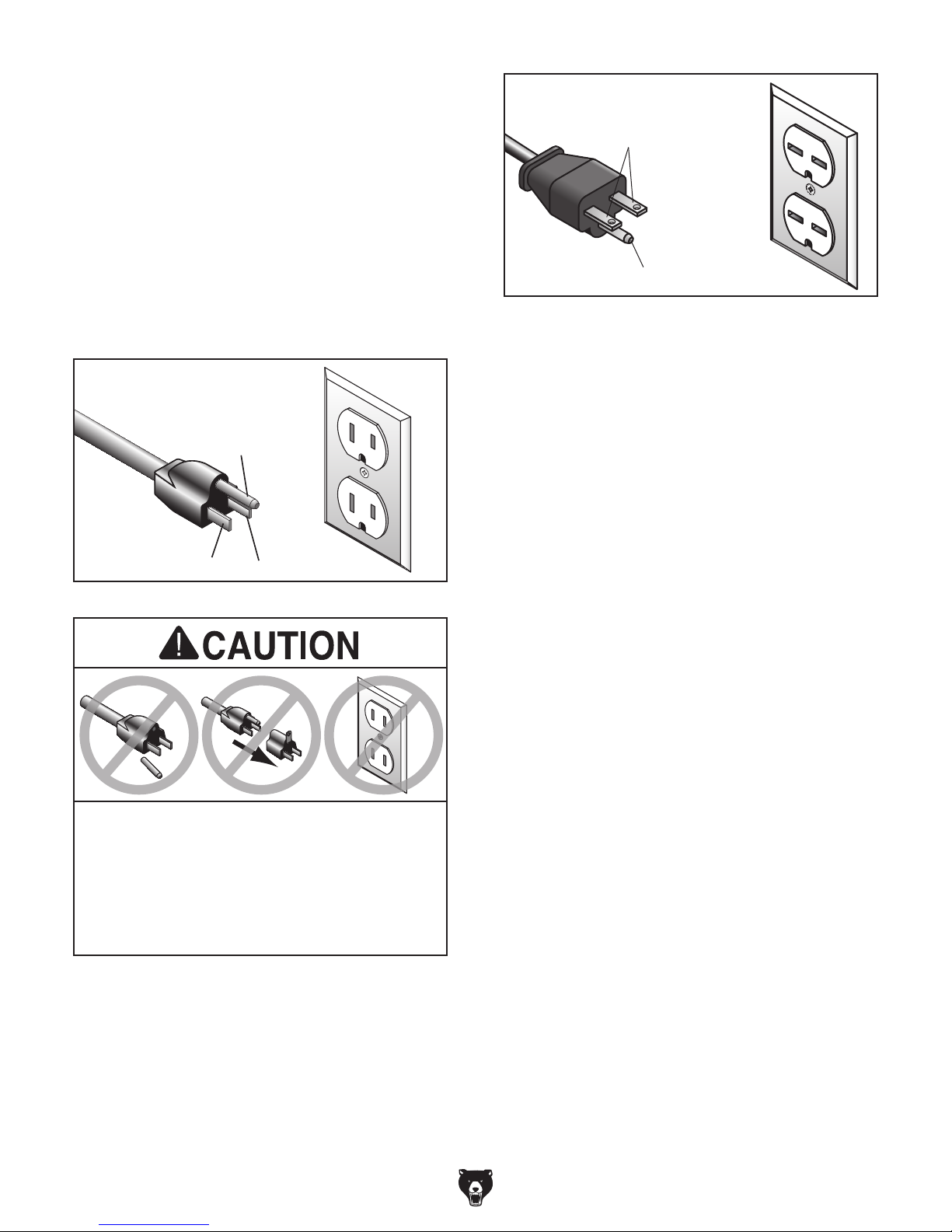
For 110V operation: This machine is equipped
with a power cord that has an equipment-grounding wire and a grounding plug (see following figure). The plug must only be inserted into a matching receptacle (outlet) that is properly installed
and grounded in accordance with all local codes
and ordinances.
For 220V operation: The plug specified under
“
page has a grounding prong that must be attached
to the equipment-grounding wire on the included
power cord. The plug must only be inserted into
a matching receptacle (see following figure) that
is properly installed and grounded in accordance
with all local codes and ordinances.
it will not fit the outlet, have a qualified
electrician install the proper outlet with a
GROUNDED
5-15 RECEPTACLE
Grounding Prong
5-15 PLUG
GROUNDED
6-15 RECEPTACLE
Current Carrying Prongs
6-15 PLUG
Grounding Prong
Figure 6. Typical 6-15 plug and receptacle.
Neutral Hot
Figure 5. Typical 5-15 plug and receptacle.
SHOCK HAZARD!
Two-prong outlets do not meet the grounding
requirements for this machine. Do not modify
or use an adapter on the plug provided—if
verified ground.
Circuit Requirements for 220V” on the previous
-14-
Extension Cords
If you must use an extension
Minimum Gauge Size ...........................14 AWG
Maximum Length (Shorter is Better).......50 ft.
Model G0813/G0814 (Mfd. Since 3/16)
Page 17
Voltage Conversion
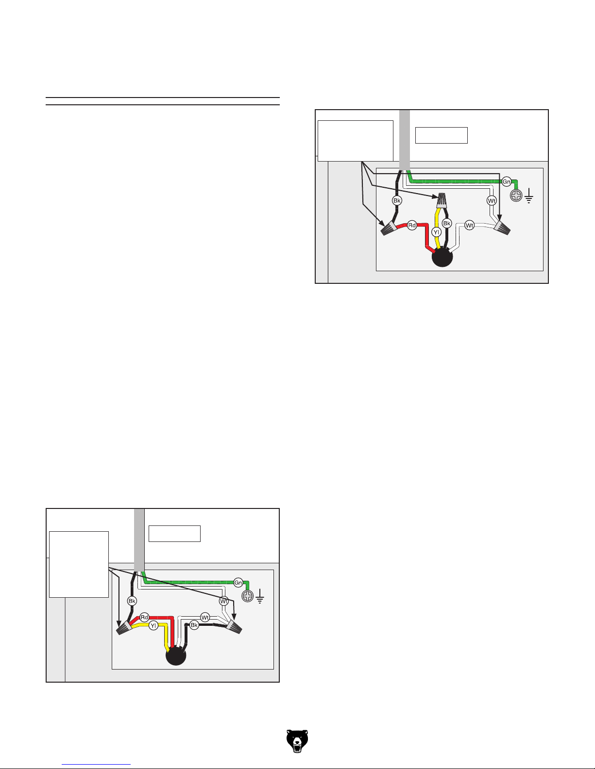
to 220V
4. Use wire nuts to connect wires as indicated
in Figure 8. Twist wire nuts onto their respective wires and wrap them with electrical tape
so they will not come loose.
The voltage conversion MUST be performed by
an electrician or qualified service personnel.
The voltage conversion procedure consists of
rewiring the motor and installing the correct plug.
A wiring diagram is provided on Page 56 for your
reference.
IMPORTANT: If the diagram included on the
motor conflicts with the one on Page 56, the motor
may have changed since the manual was printed.
Use the diagram provided on the motor junction
box instead.
Items Needed Qty
• Phillips Head Screwdriver #2 ..................... 1
• Electrical Tap e ............................ As Needed
• Wire Nut (16 AWG x 3) ............................... 1
• 6-15 Plug .................................................... 1
• Wire Cutters/Stripper .................................. 1
To convert Model G0813/G0814 to 220V:
Connect Wires
and Secure
with Nuts
Figure 8. Motor rewired to 220V.
5. Close and secure motor junction box.
6. Install a 6-15 plug according to manufac-
turer's instructions. If plug manufacturer's
instructions are not available, NEMA standard 6-15 plug wiring is provided on Page 56.
To Switch
Ground
1. DISCONNECT MACHINE FROM POWER!
2. Cut off existing 5-15 plug.
3. Open motor junction box, remove two wire
nuts indicated in Figure 7, then disconnect
wires.
Remove
Wire
Nuts and
Disconnect
Wires
Figure 7. Inside motor junction box (motor pre-
To Switch
Ground
wired to 120V).
Model G0813/G0814 (Mfd. Since 3/16)
-15-
Page 18
SECTION 3: SETUP
This machine was carefully packaged for safe
transport. When unpacking, separate all enclosed
items from packaging materials and inspect them
for shipping damage.
,
please
IMPORTANT:
you are completely satisfied with the machine and
have resolved any issues between Grizzly or the
shipping agent. You MUST have the original pack-
aging to file a freight claim. It is also extremely
helpful if you need to return your machine later.
Keep children and pets away
from plastic bags or packing
materials shipped with this
get help from other people
The following items are needed, but not included,
for the setup/assembly of this machine.
Needed for Setup
This machine presents
serious injury hazards
to untrained users. Read
through this entire manual
to become familiar with
the controls and operations before starting the
machine!
Wear safety glasses during
the entire setup process!
Description Qty
• Safety Glasses (for each person) ............... 1
• Solvent/Cleaner .......................................... 1
• Shop Rags .................................................. 1
• Wrench or Socket 14mm ......................1 Ea.
• Hex Wrench 2.5mm ..............................1 Ea.
• Straightedge 4' ........................................... 1
• Stubby Phillips Screwdriver #2 ................... 1
• Dust Collection System .............................. 1
• 4" Dust Hose (length as needed) ............... 1
• 4" Hose Clamp ........................................... 1
• Another Person .......................................... 1
HEAVY LIFT!
Straining or crushing injury
may occur from improperly
lifting machine or some of
its parts. To reduce this risk,
and use a forklift (or other
lifting equipment) rated for
weight of this machine.
Unpacking
If items are damaged
call us immediately at (570) 546-9663.
Save all packaging materials until
SUFFOCATION HAZARD!
machine. Discard immediately.
-16 -
Model G0813/G0814 (Mfd. Since 3/16)
Page 19

Hardware Recognition Chart
5mm
Model G0813/G0814 (Mfd. Since 3/16)
5mm
-17-
Page 20

G0813 Inventory
The following is a list of items shipped with your
machine. Before beginning setup, lay these items
out and inventory them.
If any non-proprietary parts are missing (e.g. a
nut or a washer), we will gladly replace them; or
for the sake of expediency, replacements can be
obtained at your local hardware store.
NOTICE
If you cannot find an item on this list, carefully check around/inside the machine and
packaging materials. Often, these items get
lost in packaging materials while unpacking or they are pre-installed at the factory.
A
B
Box Inventory (Figures 9–10) Qty
A. Jointer Assembly w/Carriage Mount ........... 1
B. Motor .......................................................... 1
C. Fence Assembly & Carriage ..................... 1
D. Cutterhead Guard ....................................... 1
E. Belt Guard .................................................. 1
F. Knife-Setting Jig ......................................... 1
G. Push Blocks ................................................ 2
H. Hex Wrench 3mm .................................1 Ea.
I. Belt ............................................................. 1
J. Fence Lock w/Locking Nut ......................... 1
K. Fence Tilt Handle ....................................... 1
L. Open-End Wrenches 8/10, 12/14mm ...1 Ea.
M. Front Panel w/Switch .................................. 1
N. Right Panel ................................................. 1
O. Left Panel ................................................... 1
P. Rear Panel (w/Switch Box, Cords) ............. 1
Q. Corner Supports ......................................... 4
R. Top Plate .................................................... 1
S. Dust Port .................................................... 1
T. Foot Pedal Caster Assembly ...................... 1
U. Motor Mount Plate ...................................... 1
V. Left Chute Support ..................................... 1
W. Right Chute Panel ...................................... 1
X. Mobile Base Chassis .................................. 1
C
F
G
I
J
Figure 9. Box inventory.
M N
Q
R
V
D
K L
O
Fasteners (see Hardware Recognition Chart)
3
• Flange Screws #10-24 x
E
H
P
S
• Hex Nuts #10-24 (Stand) ............................ 4
5
• Carriage Bolts
• Flat Washers
• Hex Nuts
• Hex Bolts
• Flat Washers
• Hex Nuts
• Hex Bolts
• Flat Washers
• Hex Nuts
• Hex Bolt
5
• Flat Washer
• Hex Bolts
• Flat Washers
• Hex Bolt
5
• Flat Washer
⁄16"-18 x 3⁄4" (Motor/Stand) . . 4
5
⁄16" (Motor/Stand) ................. 4
5
⁄16"-18 (Motor/Stand) .................. 4
3
⁄8"-16 x 1" (Mb. Base/Stand) ..... 4
3
⁄8" (Mobile Base/Stand) ....... 8
3
⁄8"-16 (Mobile Base/Stand) ........ 4
3
⁄8"-16 x 21⁄2 " (Wheel/Stand) ....... 2
3
⁄8" (Wheel/Stand) ................ 4
3
⁄8"-16 ( Wheel/Stand) .................. 2
⁄16"-18 x 2" (Wheel/Stand) ........... 1
5
⁄16" (Wheel/Stand) ................. 1
3
⁄8"-16 x 3⁄4" (Jointer/Stand) ......... 3
3
⁄8" (Jointer/Stand) ................ 3
⁄16"-18 x 21⁄2 " (Belt Guard) ........... 1
5
⁄16" (Belt Guard) ..................... 1
• Flange Screws #10-24 x
⁄8" (Stand) ........ 54
3
⁄8" (Dust Port) ..... 4
X
T
U
W
Figure 10. Additional box inventory.
-18-
Model G0813/G0814 (Mfd. Since 3/16)
Page 21
G0814 Inventory
The following is a list of items shipped with your
machine. Before beginning setup, lay these items
out and inventory them.
If any non-proprietary parts are missing (e.g. a
nut or a washer), we will gladly replace them; or
for the sake of expediency, replacements can be
obtained at your local hardware store.
NOTICE
If you cannot find an item on this list, carefully check around/inside the machine and
packaging materials. Often, these items get
lost in packaging materials while unpacking or they are pre-installed at the factory.
A
B
C
D
Box Inventory (Figures 11-12) Qty
A. Jointer Assembly w/Carriage Mount ........... 1
B. Fence Assembly & Carriage ...................... 1
C. Cutterhead Guard ....................................... 1
D. Belt Guard .................................................. 2
E. Knife-Setting Jig ......................................... 1
F. Push Blocks ................................................ 2
G. Hex Wrench 3mm .................................1 Ea.
H. Belt ............................................................. 1
I. Fence Lock w/Locking Nut ......................... 1
J. Fence Tilt Handle ....................................... 1
K. Open-End Wrenches 8/10, 12/14mm ...1 Ea.
L. Dust Port .................................................... 1
M. Stand Assembly w/Motor ........................... 1
N. Foot Pedal Caster Assembly ...................... 1
Fasteners (see Hardware Recognition Chart)
3
• Hex Bolts
• Flat Washers
• Hex Nuts
• Hex Bolt
• Flat Washer
• Hex Bolts
• Flat Washers
• Hex Bolt
• Flat Washer
• Flange Screws #10-24 x
⁄8"-16 x 21⁄2 " (Wheel/Stand) ....... 2
3
⁄8" (Wheel/Stand) ................ 4
3
⁄8"-16 ( Wheel/Stand) .................. 2
5
⁄16"-18 x 2" (Wheel/Stand) ........... 1
5
⁄16" (Wheel/Stand) ................. 1
3
⁄8"-16 x 3⁄4" (Jointer/Stand) ......... 3
3
⁄8" (Jointer/Stand) ................ 3
5
⁄16"-18 x 21⁄2 " (Belt Guard) ........... 1
5
⁄16" (Belt Guard) ..................... 1
3
⁄8" (Dust Port) ..... 4
F
E
I
J
H
Figure 11. Box inventory.
M
L
N
Figure 12. Additional box inventory.
Model G0813/G0814 (Mfd. Since 3/16)
G
K
-19 -
Page 22
The unpainted surfaces of your machine are
coated with a heavy-duty rust preventative that
prevents corrosion during shipment and storage.
This rust preventative works extremely well, but it
will take a little time to clean.
Be patient and do a thorough job cleaning your
machine. The time you spend doing this now will
give you a better appreciation for the proper care
of your machine's unpainted surfaces.
There are many ways to remove this rust preventative, but the following steps work well in a wide
variety of situations. Always follow the manufacturer’s instructions with any cleaning product you
use and make sure you work in a well-ventilated
area to minimize exposure to toxic fumes.
Before cleaning, gather the following:
• Disposable rags
• Cleaner/degreaser (WD•40 works well)
• Safety glasses & disposable gloves
• Plastic paint scraper (optional)
Basic steps for removing rust preventative:
1.
2.
3.
4.
Many cleaning solvents
work in a well-ventilated
Avoid chlorine-based solvents, such as
Cleanup
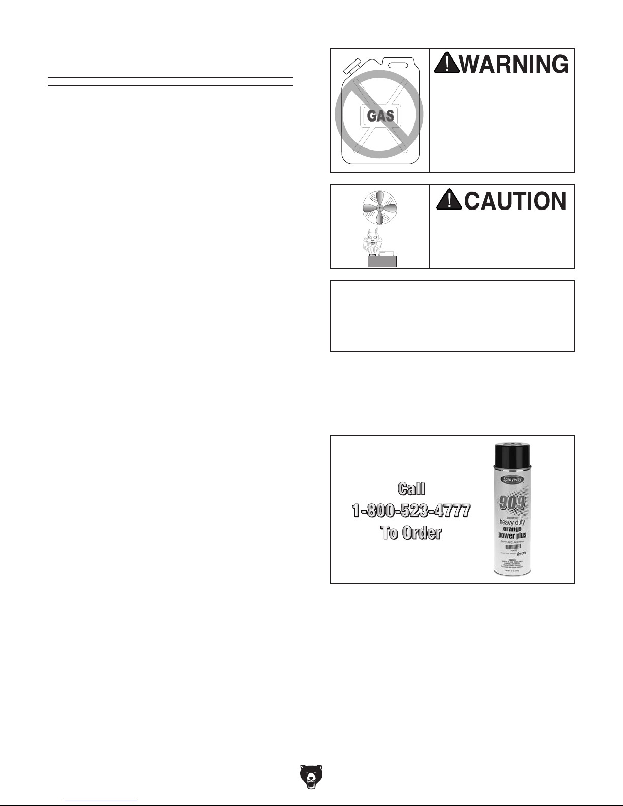
Gasoline and petroleum
products have low flash
points and can explode
or cause fire if used to
clean machinery. A v oi d
using these products
to clean machinery.
Put on safety glasses.
Coat the rust preventative with a liberal
amount of cleaner/degreaser, then let it soak
for 5–10 minutes.
Wipe off the surfaces. If your cleaner/degreas-
er is effective, the rust preventative will wipe
off easily. If you have a plastic paint scraper,
scrape off as much as you can first, then wipe
off the rest with the rag.
Repeat Steps 2–3 as necessary until clean,
then coat all unpainted surfaces with a quality
metal protectant to prevent rust.
are toxic if inhaled. Only
area.
NOTICE
acetone or brake parts cleaner, that may
damage painted surfaces.
T23692—Orange Power Degreaser
A great product for removing the waxy shipping grease from the non-painted parts of the
machine during clean up.
Figure 13. T23692 Orange Power Degreaser.
-20-
Model G0813/G0814 (Mfd. Since 3/16)
Page 23

Site Considerations
Weight Load
Refer to the
of your machine. Make sure that the surface upon
which the machine is placed will bear the weight
of the machine, additional equipment that may be
installed on the machine, and the heaviest workpiece that will be used. Additionally, consider the
weight of the operator and any dynamic loading
that may occur when operating the machine.
Space Allocation
Consider the largest size of workpiece that will
be processed through this machine and provide
enough space around the machine for adequate
operator material handling or the installation of
auxiliary equipment. With permanent installations,
leave enough space around the machine to open
or remove doors/covers as required by the maintenance and service described in this manual.
See below for required space allocation.
Physical Environment
Extreme conditions for this type of machinery are
Place this machine near an existing power source.
other hazards. Make sure to leave enough space
Shadows, glare, or strobe effects that may distract
or impede the operator must be eliminated.
Machine Data Sheet for the weight
Children or untrained people
may be seriously injured by
this machine. Only install in an
access restricted location.
The physical environment where the machine is
operated is important for safe operation and longevity of machine components. For best results,
operate this machine in a dry environment that is
free from excessive moisture, hazardous chemicals, airborne abrasives, or extreme conditions.
generally those where the ambient temperature
range exceeds 41°–104°F; the relative humidity
range exceeds 20%–95% (non-condensing); or
the environment is subject to vibration, shocks,
or bumps.
Electrical Installation
Make sure all power cords are protected from
traffic, material handling, moisture, chemicals, or
around machine to disconnect power supply or
apply a lockout/tagout device, if required.
Lighting
for Maintenance
Lighting around the machine must be adequate
enough that operations can be performed safely.
Wall
Min. 30"
= Electrical Connection
Figure 14. Minimum working clearances.
Model G0813/G0814 (Mfd. Since 3/16)
471/2"
20"
-21-
Page 24

Assembly
The machine must be fully assembled before it
can be operated. Before beginning the assembly
process, refer to
and gather all
listed i
To make sure the assembly process
goes smoothly, first clean all
that have any
heavy-duty rust preventative
tory (if applicable).
2. Hold motor mount plate level, attach it to top
3
of chute supports with (2) #10-24 x
⁄8" flange
screws, then pivot plate down and install
3
(4) #10-24 x
⁄8" additional flange screws
(see Figure 16).
Needed for Setup
tems.
parts
applied by the fac-
The Model G0813 jointer stand must be assembled. The Model G0814 stand requires no assembly. Therefore, if assembling the Model G0813,
start at Step 1. If assembling the Model G0814,
start at Step 18 on Page 25.
To assemble jointer:
1. Place top plate upside down on level surface,
then attach left and right chute supports to
3
top plate with (4) #10-24 x
⁄8" flange screws
and #10-24 hex nuts, as shown in Figure 15.
Ensure flanges face outward.
Left
Flange
Support
Top Plate
Right Support
Note: Flange screws must be installed from
inside of chute supports.
Motor
Mount
x 6
Plate
Chute
Support
Figure 16. Motor mount plate attached to chute
supports.
3. Attach motor to base so pulley is aligned with
5
belt slot in top plate using (4)
5
carriage bolts, (4)
5
⁄16"-18 hex nuts (see Figure 17).
⁄16" flat washers, and (4)
⁄16"-18 x 3⁄4"
Note: Do not tighten any fasteners until
further instructed.
x 4
Figure 15. Dust chute supports attached to top
plate.
-22-
Pulley
Belt Slot
x 4
Dust Chute
Base
Figure 17. Motor attached to dust chute base.
Model G0813/G0814 (Mfd. Since 3/16)
Page 25

4. Attach each of the four corner supports to top
GND
GND
3
plate with (4) #10-24 x
⁄8" flange screws, as
shown in Figure 18. Ensure flange of each
support is installed inside top plate.
Corner
Support
6. Attach motor cord and power cord wires to
ON/OFF switch terminals (see Figure 20).
Ensure motor cord wires attach to horizontal
terminals and power cord wires attach to vertical terminals.
Horizontal Terminal
Motor Cord
x 4
Figure 18. Corner supports attached to top
plate.
5. Attach front and rear panels to corner sup-
3
ports with (7) #10-24 x
⁄8" flange screws each
(see Figure 19). Orient panels upside down
so ON/OFF switch (front panel) and power
cord (rear panel) are at bottom.
Rear
Panel
Front
Panel
Power
Cord
ON/OFF
Switch
Vertical
Terminal
Power Cord
Horizontal
Terminal
Motor
Cord
GND
GND
Vertical
Terminal
Power
Cord
Figure 20. Wires connected to ON/OFF switch
terminals.
7. Attach switch box to front panel with (2) pre-
3
installed #10-24 x
⁄8" flange screws (see
Figure 21).
Front
Panel
Motor
Cord
Figure 19. Front and rear panels attached to
corner supports.
Model G0813/G0814 (Mfd. Since 3/16)
x 7
x 2
Switch Box
Figure 21. Switch box attached to front panel.
-23-
Page 26

8. Remove motor junction box cover, loosen
strain relief, then insert motor cord into junction box, as shown in Figure 22.
9. Attach ground wire with pre-installed ground
wire screw (see Figure 22).
Strain Relief
Ground
Wire Screw
Wire Nut (1 of 2)
Figure 22. Inserting wires into junction box.
10. Remove wire nuts (see Figure 22) and dis-
connect wires, then use wire nuts to reconnect wires, as indicated in Figure 23. Twist
wire nuts onto their respective wires and
wrap them with electrical tape so they will not
come loose (see Figure 23).
Connect
To Switch
Wire Nuts
and Wires
14. Attach right panel to corner supports with (6)
3
#10-24 x
⁄8" flange screws (see Figure 24).
Right
Panel
x 6
Figure 24. Right panel attached to stand.
15. Attach left panel with dust chute to corner
supports using (6) #10-24 x
3
⁄8" flange screws
(see Figure 25).
Left
Panel
x 6
Ground
Figure 23. Wires connected inside motor
junction box.
11. Make sure wires have enough slack between
strain relief and wire nuts so they are not
pulled tight or stretched, then tighten strain
relief against outer jacket of cord to secure it.
12. Test strain relief to ensure it is properly
tightened by pulling cord from outside junction box with light-to-moderate force. When
strain relief is properly tightened, cord will not
move inside junction box.
13. Re-install junction box cover.
-24-
Figure 25. Left panel attached to stand.
16. Position mobile base chassis on stand so
wheels are on same side as dust chute, then
3
secure base with (4)
3
⁄8" flat washers, and (4) 3⁄8"-16 hex nuts, as
⁄8"-16 x 1" hex bolts, (8)
shown in Figure 26.
Chassis
Dust Chute
x 4
Figure 26. Mobile base chassis attached to
stand.
Model G0813/G0814 (Mfd. Since 3/16)
Page 27

17. Tighten all fasteners on stand.
18. G0814 Only: Turn stand upside down and
place top on flat surface.
22. With help of another person, place jointer
assembly onto stand. Attach jointer assembly
3
to stand with (3)
3
⁄8" flat washers (see Figure 28).
⁄8"-16 x 3⁄4" hex bolts and (3)
19. Attach foot pedal caster assembly to side of
mobile base chassis with leveling feet, using
3
⁄8"-16 x 21⁄2" hex bolts, (4) 3⁄8" flat wash-
(2)
ers, (2)
hex bolt and (1)
3
⁄8"-16 hex nuts, and (1) 5⁄16"-18 x 2"
5
⁄16" flat washer, as shown in
Figure 27.
x 2
(Interior View)
Note: Mounting requires reaching through
dust chute to install a hex bolt and washer on
left side of stand. Ensure cutterhead pulley is
positioned above slot in top of cabinet stand.
Slot
x 3
Figure 28. Jointer assembly attached to stand.
23. Place straightedge against pulleys to check
their alignment (see Figures 29–30).
— If pulleys are aligned, go to Step 25.
— If pulleys are not aligned, go to Step 24.
x 1
Figure 27. Pedal assembly attached to right side
of stand.
20. Place stand in upright position and adjust leveling feet as needed with hex nuts so stand
rests level and stable on floor.
21. Remove rear panel to access mounting holes
in stand during next step.
Straightedge
Figure 29. Checking belt alignment.
Cutterhead
Pulley
Alignment
Motor
Pulley
Figure 30. Pulley alignment.
Model G0813/G0814 (Mfd. Since 3/16)
-25-
Page 28

24. Loosen set screws on cutterhead or motor
pulley as needed to align pulleys, then tighten
set screws (see Figure 31).
x 2
Pulley
Figure 31. Motor pulley set screw locations.
27. Adjust belt tension by applying downward
pressure on motor until there is approxi-
1
mately
⁄4" deflection when belt is pushed with
moderate force, as shown in Figure 34.
Note: After the first 16 hours of operation,
check and re-tension the belt, as it may
stretch and seat during this time, which will
cause it to lose the initial tension you set.
Cutterhead Pulley
Approximately
1
/4" Deflection
25. Loosen motor mount bolts shown in Figure
32, but DO NOT completely remove them.
Figure 32. Location of motor mount bolts/nuts
(2 of 4 shown).
26. Slide motor upward, place belt around
cutterhead and motor pulleys, then slide
motor down to rest on belt (see Figure 33).
Belt
Motor Pulley
Figure 34. Correct belt deflection when properly
tensioned.
28. Tighten motor mount bolts/nuts (see Figure
32) and replace rear panel.
29. Place fence onto fence carriage base, mak-
ing sure it fits over key (see Figure 35), then
insert fence lock and thread on locking nut.
Top View
Fence
Lock
Fence
Key
Carriage
Base
Figure 33. Belt installed onto cutterhead and
motor pulleys.
-26-
Bottom View
Fence
Lock
Figure 35. Fence assembly installed onto
carriage base and secured with fence lock.
Model G0813/G0814 (Mfd. Since 3/16)
Page 29

30. Install fence tilt lever (see Figure 36).
When outfeed table height is correctly set,
knife (at top dead center) will barely touch
straightedge, as illustrated in Figure 37.
Tilt Lever
Figure 36. Fence tilt lever installed.
The outfeed table MUST be level with
cutterhead knives when they are at top
dead center (at their highest point during rotation). Otherwise, the workpiece
cannot properly feed past the cutterhead,
which may cause a kickback hazard for
the operator.
31. Place straightedge on outfeed table so it
extends over cutterhead, and use cutterhead
pulley to rotate cutterhead until one of the
knives is at top dead center (their highest
point during rotation), as illustrated in Figure
37.
Top Dead
Center
— If knife lifts straightedge off table or is
below straightedge, then outfeed table
height must be reset (refer to Setting
Outfeed Table Height, Steps 5-8, on
Page 48 for detailed instructions).
32. Remove set screw from forked end of
cutterhead guard shaft, wind torsion spring
1
knob
⁄2-turn counterclockwise (viewed from
top), then slide shaft down through mounting
hole on table.
Note: The guard may not fully seat in hole ini-
tially; however, rotating guard will allow shaft
to fully seat in hole.
33. Thread set screw through forked end of
cutterhead guard shaft, as shown in Figure 38.
When properly installed, guard is positioned
3
⁄8" above table for safety during operations.
Torsion
Spring
Knob
Forked End of
Shaft
Straightedge
Outfeed Infeed
Figure 37. Using straightedge to check outfeed
table height.
Model G0813/G0814 (Mfd. Since 3/16)
Figure 38. Set screw threaded into end of
cutterhead guard shaft.
-27-
Page 30

Cutterhead guard must always return to
closed position whenever it is moved. If it
does not do this, it must be re-adjusted or
re-installed.
34. Test operation of guard by pulling it back.
Guard should spring back over cutterhead
and stop against fence.
— If guard does not snap back, or snaps
back slowly, remove guard and repeat
Steps 32–34.
36. Assemble knife-setting gauge, as shown in
Figure 40.
35. Install belt guard with (1)
5
bolt and (1)
⁄16" flat washer (see Figure 39).
x 1
Figure 39. Belt guard installed.
5
⁄16"-18 x 21⁄2" hex
Figure 40. Knife-setting gauge assembled.
37. Install dust port, as shown in Figure 41, using
3
(4) #10-24 x
⁄4" flange screws.
x 4
Figure 41. Dust port installed.
-28-
Model G0813/G0814 (Mfd. Since 3/16)
Page 31

Dust Collection
Once assembly is complete, test run the machine
to ensure it is properly connected to power and
safety components are functioning correctly.
If you find an unusual problem during the test run,
immediately stop the machine, disconnect it from
power, and fix the problem BEFORE operating the
machine again. The
table in the
SERVICE section of this manual can help.
DO NOT start machine until all preceding
setup instructions have been performed.
Operating an improperly set up machine
connecting machine to power before
This machine creates substantial amounts
of dust during operation. Breathing airborne dust on a regular basis can result in
permanent respiratory illness. Reduce your
risk by wearing a respirator and capturing
the dust with a dust collection system.
Recommended CFM at Dust Port: 400 CFM
Do not confuse this CFM recommendation with
the rating of the dust collector. To determine the
CFM at the dust port, you must consider these
variables: (1) CFM rating of the dust collector,
(2) hose type and length between the dust collector and the machine, (3) number of branches
or wyes, and (4) amount of other open lines
throughout the system. Explaining how to calculate these variables is beyond the scope of
this manual. Consult an expert or purchase a
good dust collection "how-to" book.
Test Run
Troubleshooting
Serious personal injury could occur from
completing the setup process described in
this manual. DO NOT connect power until
instructed to do so later in this manual.
To connect dust collection hose:
1. Fit 4" dust hose over dust port, as shown in
Figure 42, and secure with a hose clamp.
Figure 42. Example of dust hose attached to
dust port.
2. Tug hose to make sure it does not come off.
Note: A tight fit is necessary for proper
performance.
Model G0813/G0814 (Mfd. Since 3/16)
may result in malfunction or unexpected results that can lead to serious injury,
death, or machine/property damage.
To test run the machine:
1. Clear all setup tools away from machine.
2. Connect machine to power supply.
3. Turn machine ON, verify motor operation,
and then turn machine OFF.
The motor should run smoothly and without
unusual problems or noises.
-29-
Page 32

4. Remove switch disabling key, as shown in
Figure 43.
Recommended
Adjustments
For your convenience, the adjustments listed
below have been performed at the factory and no
further setup is required to operate your machine.
However, because of the many variables involved
with shipping, we recommend that you at least
verify the following adjustments to ensure the best
possible results from your new machine.
Figure 43. Removing switch key from paddle
switch.
5. Try to start machine with paddle switch. The
machine should not start.
— If the machine does not start, the switch
disabling feature is working as designed.
Congratulations! The test run is complete.
Proceed to Recommended Adjustments.
— If the machine does start, immediately stop
the machine. The switch disabling feature
is not working correctly. This safety feature must work properly before proceeding
with regular operations. Call Tech Support
for help.
Step-by-step instructions for these adjustments
can be found in SECTION 7: SERVICE.
Factory adjustments that should be verified:
1. Knife Settings (Page 45).
2. Depth Scale Calibration (Page 49).
3. Fence Stop Accuracy (Page 50).
4. Table Parallelism (Page 53).
-30-
Model G0813/G0814 (Mfd. Since 3/16)
Page 33

SECTION 4: OPERATIONS
This overview covers the basic process that
happens during a typical operation with this
machine. Familiarize yourself with this process
to better understand the controls and procedures
explained throughout the Operations section.
To complete a typical operation with the
jointer
1.
2.
3.
4.
5.
6.
7.
8.
9.
10. Stops jointer.
The purpose of this overview is to provide the novice machine operator with a basic understanding
of how the machine is used during operation, so
the
discussed later
in this manual
Due to the generic nature of this overview, it is
not intended to be an instructional guide. To learn
more about specific operations, read this entire
manual and
rienced
research outside of this manual by reading "howto" books, trade magazines, or websites.
To reduce your risk of
serious injury, read this
entire manual BEFORE
To reduce risk of eye injury from flying
Operation Overview
machine controls/components
are easier to understand.
seek additional training from expe-
machine operators, and do additional
using machine.
, the operator does the following:
Examines workpiece to verify it is safe and
suitable for cutting.
Adjusts fence for width of workpiece and
locks it in place.
Adjusts fence tilt, if necessary.
Adjusts infeed table height to set depth of cut
per pass.
Puts on safety glasses, respirator, and ear
protection.
Locates push blocks.
Starts jointer.
Holds workpiece firmly against infeed table
and fence, and slides it into cutterhead at a
steady and controlled rate until entire length
of workpiece has advanced beyond cutterhead to outfeed table.
chips or lung damage from breathing dust,
always wear safety glasses and a respirator
when operating this machine.
If you are not experienced with this type
of machine, WE STRONGLY RECOMMEND
that you seek additional training outside of
this manual. Read books/magazines or get
formal training before beginning any projects. Regardless of the content in this section, Grizzly Industrial will not be held liable
for accidents caused by lack of training.
Model G0813/G0814 (Mfd. Since 3/16)
Repeats cutting process until desired results
are achieved.
-31-
Page 34

Stock Inspection &
Follow these rules when choosing and jointing stock:
• DO NOT joint or surface plane stock that
Injury to the
occur if a knot becomes dislodged during the
• DO NOT joint or surface plane against the
• Jointing and surface planing with the
grain produces a better finish and is safer
Figure
If the grain changes direction along the
edge of the board, decrease the cutting depth
and make additional passes.
10" Min.
1
/4" Min.
3
/4" Min.
• Scrape all glue off the workpiece before
• Remove foreign objects from the work-
Wood stacked on a concrete or dirt
surface can have small pieces of concrete or
• Make sure all stock is sufficiently dried
on the cutters and poor cutting results. Excess
• Make sure your workpiece exceeds the
minimum dimension requirements shown
before processing it through the
jointer, or the workpiece may break or
kickback during the operation.
Requirements
contains large or loose knots.
operator or damage to the workpiece can
cutting operation.
jointing. Glue deposits on the workpiece,
hard or soft, will gum up the cutterhead and
produce poor results.
piece. Make sure that any stock you process with the jointer is clean and free of dirt,
nails, staples, tiny rocks or any other foreign
objects that could damage the cutterhead.
These particles could also cause a spark as
they strike the cutterhead and create a fire
hazard.
Note:
grain direction. Cutting against the grain
increases the likelihood of kickback, as well
as tear-out on the workpiece.
for the operator. Cutting with the grain is
described as feeding the stock on the jointer
so the grain points down and toward you as
viewed on the edge of the stock (see
below).
Note:
CORRECT
With Grain
stone pressed into the surface.
before jointing. Wood with a moisture content over 20% will cause unnecessary wear
moisture can also hasten rust and corrosion.
below,
10" Min.
3
/4" Min.
INCORRECT
Against Grain
Figure 44. Proper grain alignment with the
cutterhead.
-32-
1
/4" Min.
10" Min.
1
/2" Min.
1" Min.
Figure 45. Minimum stock dimensions for jointer.
Model G0813/G0814 (Mfd. Since 3/16)
Page 35

Setting Depth of Cut
The depth of cut on a jointer is the amount of mate rial removed from the bottom of the workpiece as
it passes over the cutterhead.
The depth of cut is set by adjusting the height of
the infeed table relative to the cutterhead knives
at TDC (top dead center).
Depth-of-Cut Scale
The depth of cut can be referenced directly from
the depth scale located on the front of the jointer
(see Figures 47–48).
Note: The depth scale can be calibrated or
"zeroed" if it is not correct. Refer to Calibrating
Depth Scale on Page 49 for more information.
The depth-of-cut scale (see Figure 48 on this
page) goes up to
all other types of cuts the maximum depth of cut
should never exceed
DO NOT exceed the recommended depth of
cut per pass (
operation), or kickback and serious injury
may occur.
1
⁄2 " for cutting rabbets, but for
1
⁄8".
1
⁄16" or 1⁄8" depending on the
Adjusting Infeed Table Height
To adjust the infeed table height, loosen the infeed
table lock, adjust the infeed table lever, then tighten the lock to secure the setting (see Figure 46).
To set the maximum height (i.e. minimum depth of
cut), thread the stop bolt into the base and tighten
the jam nut shown in Figure 48.
Figure 47. Location of depth-of-cut scale.
Depth
Indicator
Stop Bolt
Infeed Table
Infeed Table Lock
Figure 46. Infeed table controls located on back
of machine.
Model G0813/G0814 (Mfd. Since 3/16)
Lever
Jam NutScale
Figure 48. Depth-of-cut scale components.
-33-
Page 36

Squaring Stock
Squaring stock involves four steps performed
—Concave face of
2. Surface Plane on a Thickness Planer—
Opposite face of workpiece is surface planed
3. Edge Joint on Jointer—Concave edge of
4. Rip Cut on a Table Saw—Jointed edge
in the order below:
1. Surface Plane on Jointer
workpiece is surface planed flat with jointer.
flat with a thickness planer.
workpiece is jointed flat with jointer.
of workpiece is placed against a table saw
fence and opposite edge cut off.
Previously
Jointed
45
30
15
Edge
Previously Surface
Planed Face
-34-
Model G0813/G0814 (Mfd. Since 3/16)
Page 37

To surface plane on jointer:
1.
Stock Inspection &
2.
" per pass when
3.
4.
5.
To ensure workpiece remains
stable during cut, concave sides of workpiece
6.
from cutterhead during the entire cut. Instead
safely reposition it on the outfeed side to continue supporting workpiece. Use push blocks
7.
When squaring up stock, cut opposite
side of workpiece with a planer instead of the
jointer to ensure boths sides are parallel.
Surface Planing
Failure to use push blocks when surface
ing rotating cutterhead, which will cause
serious personal injury. ALWAYS use push
The purpose of surface planing (see Figures
below) on the jointer is to make one flat face on a
piece of stock to prepare it for thickness planing
on a planer.
planing could result in your hands contact-
blocks when surface planing on jointer!
NOTICE
If you are not experienced with a jointer,
set depth of cut to 0", and practice feeding
workpiece across tables as described. This
will help you prepare for actual operations.
Inspect stock to ensure it is safe and suitable
for the operation (see
Requirements section).
Set infeed table height to desired cutting
depth for each pass.
IMPORTANT: For safety reasons, do not
exceed a cutting depth of
surface planing.
Set fence to 90˚.
Start jointer.
Place workpiece firmly against fence and
infeed table.
IMPORTANT:
must face toward table and fence.
Feed workpiece completely across cutter-
head while keeping it firmly against fence
and tables during the entire cut.
IMPORTANT: Keep hands at least 4" away
of allowing a hand to pass directly over cutterhead, lift it up and over cutterhead, and
1
⁄16
Removed
Surface
Figure 49. Example photo of a surface planing
Model G0813/G0814 (Mfd. Since 3/16)
operation.
whenever practical to further reduce risk of
accidental hand contact with cutterhead.
Repeat Step 6 until entire surface is flat.
Tip:
-35-
Page 38

Edge Jointing
To edge joint on jointer:
1.
Stock Inspection &
2.
3.
4.
5.
To ensure workpiece remains
stable during cut, concave sides of workpiece
6.
from cutterhead during the entire cut. Instead
safely reposition it on the outfeed side to continue supporting workpiece. Use push blocks
7.
When squaring up stock, cut opposite
edge of workpiece with a table saw instead
both edges of work-
piece will not be parallel with each other.
Edge jointing (see Figures below) produces a flat
and true surface along the side of a workpiece
by removing uneven areas.
an essential step
for
and when
preparing a workpiece for joinery or finishing.
squaring up warped or rough stock
It is
NOTICE
If you are not experienced with a jointer,
set depth of cut to 0", and practice feeding
workpiece across tables as described. This
will help you prepare for actual operations.
Inspect stock to ensure it is safe and suitable
for the operation (see
Requirements section).
Set infeed table height to desired cutting
depth for each pass.
Removed
Figure 50. Example photo of an edge jointing
Surface
operation.
IMPORTANT: For safety reasons, cutting
depth should never exceed
Set fence to 90˚.
Start jointer.
Place workpiece firmly against fence and
infeed table.
IMPORTANT:
must face toward table and fence.
Feed workpiece completely across cutter-
head while keeping it firmly against fence
and tables during the entire cut.
IMPORTANT: Keep hands at least 4" away
of allowing a hand to pass directly over cutterhead, lift it up and over cutterhead, and
1
⁄8" per pass.
-36-
whenever practical to further reduce risk of
accidental hand contact with cutterhead.
Repeat Step 6 until the entire edge is flat.
Tip:
of the jointer—otherwise,
Model G0813/G0814 (Mfd. Since 3/16)
Page 39

Bevel Cutting
To bevel cut on jointer:
1.
Stock Inspection &
2.
Cutting depth for bevel cuts is typically
, depending on hardness
3.
4.
5.
6.
When your leading hand gets within
4" of the cutterhead, lift it up and over cutterhead, and place push block on portion of the
workpiece once it is 4" past cutterhead. Now,
focus your pressure on outfeed end of the
workpiece while feeding, and repeat same
action with your trailing hand when it gets
within 4" of cutterhead. To help keep your
hands safe, DO NOT let them get closer than
4" from moving cutterhead at any time during
7.
you are satisfied with the results.
Bevel cuts (see Figures below) can be made by
setting the fence at the desired angle and feeding
the workpiece firmly along the fence face, with the
bottom inside corner firmly against the table. The
cutting process typically requires multiple passes
or cuts to bevel the entire edge of a workpiece.
NOTICE
If you are not experienced with a jointer,
set depth of cut to 0", and practice feeding
workpiece across tables as described. This
will help you prepare for actual operations.
Inspect stock to ensure it is safe and suitable
for the operation (see
Requirements section).
Set infeed table height to cutting depth
desired for each pass.
Note:
between 1⁄16" and 1⁄8"
and width of stock.
Removed
Surface
Figure 51. Example photo of fence setup for a
bevel cut of 45°.
Set fence tilt to desired angle of cut.
Place workpiece against fence and infeed
table with concave side face down.
Start jointer.
With a push block in your leading hand, press
workpiece against table and fence with firm
pressure, and feed workpiece over cutterhead with a push block in your trailing hand.
Note:
Model G0813/G0814 (Mfd. Since 3/16)
operation!
Repeat cutting process, as necessary, until
-37-
Page 40

Rabbet Cutting
To rabbet cut on jointer:
1.
Stock Inspection &
2.
3
4.
5.
6.
To ensure workpiece remains
stable during cut, concave sides of workpiece
7.
from cutterhead during the entire cut. Instead
safely reposition it on the outfeed side to continue supporting workpiece. Use push blocks
8. Repeat Step 7 until rabbet is cut to depth.
The purpose of rabbet cutting is to remove a section of the workpiece edge (see
).
When combined with another rabbet cut edge, the
rabbet joints create a simple, yet strong method of
joining stock.
When cutterhead guard is removed,
attempting any other cut besides a rabbet
directly exposes operator to moving cutterhead. ALWAYS replace cutterhead guard
after rabbet cutting!
Figures below
NOTICE
If you are not experienced with a jointer,
set depth of cut to 0", and practice feeding
workpiece across tables as described. This
will help you prepare for actual operations.
Inspect stock to ensure it is safe and suitable
for the operation (see
Requirements section).
Set infeed table height to desired cutting
depth for each pass.
IMPORTANT: For safety reasons, cutting
depth should never exceed
. Remove cutterhead guard.
1
⁄8" per pass.
Rabbet Joints
Removed
Surface
Set fence to 90˚ and near front of jointer,
so amount of exposed cutterhead in front of
fence matches size of desired rabbet.
Start jointer.
Place workpiece firmly against fence and
infeed table.
IMPORTANT:
must face toward table and fence.
Feed workpiece completely across cutter-
head while keeping it firmly against fence
and tables during entire cut.
IMPORTANT: Keep hands at least 4" away
of allowing a hand to pass directly over cutterhead, lift it up and over cutterhead, and
Figure 52. Example photo of typical rabbet cut-
-38-
ting operation.
whenever practical to further reduce risk of
accidental hand contact with cutterhead.
Model G0813/G0814 (Mfd. Since 3/16)
Page 41

ACCESSORIES
Installing unapproved accessories may
order online at www.grizzly.com or call 1-800-523-4777
SECTION 5: ACCESSORIES
cause machine to malfunction, resulting in
serious personal injury or machine damage.
To reduce this risk, only install accessories
recommended for this machine by Grizzly.
NOTICE
Refer to our website or latest catalog for
additional recommended accessories.
Basic Eye Protection
T20501—Face Shield Crown Protector 4"
T20502—Face Shield Crown Protector 7"
T20503—Face Shield Window
T20451—“Kirova” Clear Safety Glasses
T20452—“Kirova” Anti-Reflective S. Glasses
H7194—Bifocal Safety Glasses 1.5
H7195—Bifocal Safety Glasses 2.0
H7196—Bifocal Safety Glasses 2.5
T20502
W1211A —Jointer Pal® Magnetic Knife Gauge
(For HSS & Cobalt Knives)
W1212—Jointer Pal
(For Carbide Knives)
This magnetic knife-setting system lets you set
jointer knives in perfect alignment every time!
Figure 53. W1211A Jointer Pal® Knife Gauge.
D1123—Jointer/Planer Knife Hone
This handy tool sharpens flat and beveled surfaces quickly and easily. Great for touch-ups.
®
Magnetic Knife Gauge
T20452
T20503
H7194
Figure 55. Assortment of basic eye protection.
H2499—Small Half-Mask Respirator
H3631—Medium Half-Mask Respirator
H3632—Large Half-Mask Respirator
H3635—Cartridge Filter Pair P100
If you work around dust everyday, a half-mask
respirator can be a lifesaver. Also compatible with
safety glasses!
T20451
Figure 56. Half-mask respirator with disposable
cartridge filters.
Figure 54. D1123 Jointer Knife Hone.
Model G0813/G0814 (Mfd. Since 3/16)
-39-
Page 42

H7653—6" Spiral Cutterhead
This cutterhead replaces the standard straight
knife cutterheads on our Grizzly jointers . Has four
spirals with indexable, four-sided carbide inserts,
so each insert can be rotated for a new factory
sharp edge. Cutterhead includes cast iron pulleys,
bearing blocks, mounting studs, 5 extra inserts,
T-handle wrench, Torx bits and spare insert
screws. Has an incredible finish, and is comparable to Byrd cutterheads in quality of cut as well
as the quality of the cutterhead itself.
®
H7764—8" Byrd
Shelix Cutterhead
Made in the USA by Byrd, this indexable carbide
insert cutterhead is the best money can buy—
period! The inserts are not only placed in a spiral
pattern, they are also positioned at an angle so
the shearing action leaves a glassy smooth cut
on the toughest and most figured woods. Comes
with all 30 inserts on the cutterhead, plus 5 extras.
Great upgrade!
Figure 57. H7653 Spiral Cutterhead.
G6697— 6" x 1" x
1
⁄8" HSS Jointer Knives,
Set of 3
These jointer knives are made from M-2 high
speed steel and are hardened to 62–64 Rockwell
and tempered in a salt bath. All sets are balanced
to within one gram.
Figure 58. G6697 Replacement Knives for
G0813/G0814.
Figure 59. H7764 Byrd Shelix Cutterhead.
G1163P—1 HP Dust Collector
Effective dust collection not only keeps your shop
cleaner and more pleasant to work in, but it can
also protect your health by reducing your overall
exposure to dust. The small size and low profile
make this a perfect point-of-use, dedicated dust
collector. When it's not possible to plumb your
shop with a full dust collection system, put one of
these next to every machine instead!
-40-
Figure 60. G1163P 1 HP dust collector.
Model G0813/G0814 (Mfd. Since 3/16)
Page 43

SECTION 6: MAINTENANCE
accidental startup, always
disconnect machine from
Protect the unpainted cast iron surfaces on the
table by wiping the table clean after every use—
this ensures moisture from wood dust does not
remain on bare metal surfaces.
Keep tables rust-free with regular applications of
products like G96
, or
Boeshield
The cleaning process for this machine is simple.
Vacuum excess wood chips and sawdust, and
wipe off the remaining dust with a dry cloth. If any
resin has built up, use a resin dissolving cleaner
to remove it. Treat all unpainted cast iron and steel
with a non-staining lubricant after cleaning.
Cleaning &
To reduce risk of shock or
power before adjustments,
maintenance, or service.
Schedule
For optimum performance from your machine,
follow this maintenance schedule and refer to any
specific instructions given in this section.
Daily
• Vacuum all dust on and around the machine.
• Wipe down tables and all other unpainted
cast-iron with a metal protectant.
• Check for/repair worn or damaged wires
(Page 55).
• Check/replace damaged cutterhead or blades
(Page 45).
• Check/retighten loose mounting bolts.
• Check/resolve any other unsafe condition.
Protecting
®
®
T-9.
G5562—SLIPIT® 1 Qt. Gel
G5563—SLIPIT® 12 Oz. Spray
G2871—Boeshield® T-9 12 Oz. Spray
G2870—Boeshield® T-9 4 Oz. Spray
H3788—G96® Gun Treatment 12 Oz. Spray
H3789—G96® Gun Treatment 4.5 Oz. Spray
Gun Treatment, SLIPIT
®
Monthly
• Belt tension, damage, or wear (Page 51).
• Clean/vacuum dust buildup from inside stand
and off of motor.
Model G0813/G0814 (Mfd. Since 3/16)
Figure 61. Recommended products for
protecting unpainted cast-iron and steel.
-41-
Page 44

Lubrication
Since all bearings are sealed and permanently
lubricated, simply leave them alone until they
need to be replaced. DO NOT lubricate them.
It is essential to clean components before lubricating them because dust and chips build up on
lubricated components and make them hard to
move. Simply adding more grease to them will not
yield smooth moving components.
Clean the components below with mineral spirits
or other oil/grease solvent cleaner and shop rags.
Outfeed Table Leadscrew
Oil Type ................ SB1365 or ISO 68 Equivalent
Oil Amount ............................................Thin Coat
Frequency .......................................... As Needed
Table Ways
Oil Type .... Grizzly T23962 or ISO 68 Equivalent
Oil Amount ...........................................1–2 Drops
Lubrication Frequency ....................... As Needed
Lower infeed and outfeed tables to access ways.
Place a couple of drops of oil at top of each way
as needed, and move tables up and down to distribute oil (see Figure 64). Wipe off excess oil.
Lubricate the outfeed table leadscrew with light
machine oil as needed (see Figure 62). Wipe off
excess oil and sawdust with a cloth.
Figure 62. Leadscrew lubrication location.
SB1365—South Bend Way Oil-ISO 68
Figure 64. Location to lubricate table ways.
Fence
Oil Type .... Grizzly T23962 or ISO 68 Equivalent
Oil Amount ...........................................1–2 Drops
Lubrication Frequency ....................... As Needed
Place one or two drops of light machine oil on
fence pivot points (see Figure 65) as needed.
Figure 65. Fence lubrication locations.
Figure 63. Recommended product for machine
lubrication.
-42-
Model G0813/G0814 (Mfd. Since 3/16)
Page 45

Review the troubleshooting and procedures in this section if a problem develops with your machine. If
you need replacement parts or additional help with a procedure, call our Technical Support.
gather the serial number and manufacture date of your machine before calling.
SECTION 7: SERVICE
Troubleshooting
Motor & Electrical
Symptom Possible Cause Possible Solution
Machine does not
start or a breaker
trips immediately
after startup.
Machine stalls or is
underpowered.
Machine has
vibration or noisy
operation.
1. Switch disabling key removed.
2. Incorrect power supply voltage/circuit size.
3. Power supply circuit breaker tripped/fuse
blown.
4. Motor wires connected incorrectly.
5. Wiring open/has high resistance.
6. ON/OFF switch at fault.
7. Centrifugal switch at fault.
8. Start capacitor at fault.
9. Motor at fault.
1. Workpiece material not suitable.
2. Excessive feed rate.
3. Excessive cutting depth.
4. Dull knives.
5. Dust collection problem, causing internal
components to clog up with shavings.
6. Belt slipping; oil/grease on belt.
7. Pulley loose or not properly aligned.
8. Motor overheated.
9. Motor wires connected incorrectly.
1. Motor or other component loose.
2. Belt worn/loose; belt slapping cover.
3. Pulley loose or not properly aligned.
4. Motor fan rubbing on fan cover.
5. Foot-pedal caster engaged.
6. Knives at fault.
7. Cutterhead bearings at fault.
8. Centrifugal switch at fault.
9. Motor bearings at fault.
1. Install switch disabling key.
2. Ensure correct power supply voltage/circuit size.
3. Ensure circuit is sized correctly and free of shorts.
Reset circuit breaker or replace fuse.
4. Correct motor wiring connections (Page 55).
5. Check/fix broken, disconnected, or corroded wires.
6. Test/replace switch.
7. Adjust/replace centrifugal switch if available.
8. Test/replace capacitor.
9. Test/repair/replace.
1. Ensure workpiece is suitable for jointing (Page 32).
2. Reduce feed rate.
3. Reduce cutting depth (Page 33).
4. Sharpen/replace knives (Page 45).
5. Clear blockages; move machine closer to dust
collector; upgrade dust collector.
6. Tension/replace belt (Page 51); clean belt; ensure
pulleys are aligned (Page 52).
7. Re-align pulleys (Page 52); replace shaft key;
tighten pulley set screw(s).
8. Clean motor, let cool, and reduce depth of cut.
9. Correct motor wiring connections (Page 55).
1. Replace damaged bolts/nuts; retighten loose bolts/
nuts. Use thread-locking fluid if condition repeats.
2. Tension/replace belt (Page 51).
3. Re-align pulleys (Page 52); replace shaft key;
tighten pulley set screw(s).
4. Fix/replace fan cover; replace loose/damaged fan.
5. Release foot-pedal caster to stabilize machine.
6. Sharpen/replace knives; set knife alignment/height
correctly.
7. Replace bearing(s)/realign cutterhead.
8. Replace.
9. Test by rotating shaft; rotational grinding/loose shaft
requires bearing replacement.
Note: Please
Model G0813/G0814 (Mfd. Since 3/16)
-43-
Page 46

Machine Operation
Symptom Possible Cause Possible Solution
Table(s) difficult to
adjust.
Excessive snipe
(gouge in end of
board that is uneven
with rest of cut).
Workpiece stops in
middle of cut.
Workpiece chipping,
tear-out, or overall
rough cuts.
Fuzzy grain. 1. Wood has high moisture content.
Long lines or ridges
that run along length
of workpiece.
Uneven cutter
marks, wavy
surface, or chatter
marks across face
of workpiece.
Glossy surface;
scorching or
burn marks on
workpiece.
Workpiece is
concave or convex
along its length after
jointing.
1. Table lock(s) engaged/partially engaged.
2. Infeed table stop blocking upward
movement.
1. Outfeed table set too low, or knives set too
high.
2. Operator pushing down on trailing end of
workpiece as it leaves cutterhead.
1. Outfeed table set too high. 1. Align outfeed table with cutterhead knife at top dead
1. Not feeding workpiece to cut "with the
grain."
2. Dull knives.
3. Workpiece not suitable for jointing.
4. Nicked or chipped knives.
5. Feeding workpiece too fast.
6. Excessive cut depth.
7. Lack of proper dust collection or clogged
dust port.
2. Dull knives.
1. Nicked or chipped knives. 1. Replace knives (Page 45).
1. Feeding workpiece too fast.
2. Knives not properly adjusted.
1. Dull knives.
2. Feed rate too slow.
1. Workpiece not held with even pressure
against outfeed table during cut.
2. Workpiece too uneven at start of operation.
3. Outfeed table not parallel with infeed table.
1. Completely loosen table lock(s) (Page 4).
2. Loosen/reset infeed table stop bolt (Page 33).
1. Align outfeed table with cutterhead knife at top dead
center (Page 48); adjust height of knives evenly
with outfeed table (Page 45).
2. Reduce/eliminate downward pressure on trailing
end of workpiece as it leaves cutterhead.
center (Page 48).
1. Turn the workpiece 180° before feeding again.
2. Sharpen/replace knives (Page 45).
3. Ensure workpiece is suitable for jointing (Page 32).
4. Replace knives (Page 45).
5. Reduce feed rate.
6. Reduce cut depth (Page 33).
7. Clear blockages, ensure dust collector is operating
efficiently; upgrade dust collector.
1. Ensure wood moisture content is less than 20%.
Allow to dry if necessary (Page 32).
2. Sharpen/replace knives (Page 45).
1. Reduce feed rate.
2. Properly adjust knives (Page 45).
1. Sharpen/replace knives (Page 45).
2. Increase feed rate.
1. Apply even downward pressure against workpiece
throughout entire travel along outfeed side during
cut.
2. Take partial cuts to remove extreme high spots
before doing a full pass.
3. Check/Adjust table parallelism (Page 53).
-44-
Model G0813/G0814 (Mfd. Since 3/16)
Page 47

Inspecting Knives
The height of the knives can be inspected with a
straightedge to ensure that they are set even with
the outfeed table at their highest point in the cutterhead rotation, or top dead center (TDC).
To inspect knives:
1.
2.
3.
— Knives are set correctly set when they just
— If knives do not touch straightedge or they
need to be adjusted.
Setting the knives correctly is crucial to the proper
operation of the jointer and
important
role
higher than the others, it will do the majority of the
work, and thus,
There are two options for setting the knives—the
straightedge method and the knife-setting jig
method. Each option has advantages and disadvantages; the correct one for you will become a
matter of personal preference. For best results,
the tables must be parallel with each other (refer
to
) and
the outfeed table height must be properly set
(refer to
Straightedge Method:
edge (or Jointer Pal) is held flat against the outfeed table and the knife heights are set to the
bottom of the straightedge, as shown. Because
the knife projection height from the cutterhead is
dependent on the outfeed table height, the outfeed table must be set as described in Setting
Outfeed Table Height
correctly.
When using the straightedge method to set the
knives, you will not need to move the outfeed
table once it is set and you will always be assured
that the knives are even with the outfeed table in
their highest point of rotation (TDC)—even if the
cutterhead is not perfectly parallel with the outfeed table.
DISCONNECT MACHINE FROM POWER!
Remove cutterhead guard or block it open.
Using a straightedge on outfeed table, check
height of each knife at positions as shown.
Black Lines Represent
Straightedge Positions
From Overhead View
Setting/Replacing
Knives
it plays an
in keeping the knives sharp. If one knife is
become dull much faster.
Checking/Adjusting Table Parallelism
Setting Outfeed Table Height).
A high quality straight-
Outfeed Infeed
Straightedge
Figure 66. Using a straightedge to inspect
touch bottom of straightedge at TDC in
each of straightedge positions.
lift up at any position, then those knives
Knife at TDC
knives.
for this method to work
Straightedge
Outfeed Infeed
Model G0813/G0814 (Mfd. Since 3/16)
Figure 67. Example of setting knife heights
using straightedge method.
-45-
Page 48

Use the knife-setting jig to verify that all knives are
positioned evenly in the cutterhead.
To inspect positioning of knives in cutterhead:
1.
2.
3.
4.
5.
Repeat this inspection
with other knives before resetting.)
Setting the knives correctly is crucial to the proper
operation of the jointer and it plays an important
role in keeping the knives sharp. If one knife is
higher than the others, it will do the majority of the
work, and thus, become dull much faster.
The knife-setting jig included with the jointer is
designed to set
at the
correct height
Th
with
jack screws
the knives.
Figure 68. Example of using Jointer Pal®.
Knife-Setting Jig Method: The infeed table is
lowered to fit the jig on the cutterhead, as shown,
and the knife heights are set to just touch the
middle pad of the jig.
Tools Needed Qty
Knife-Setting Jig ................................................ 1
Hex Wrench 3mm .............................................. 1
Open-End Wrench 8mm.................................... 1
DISCONNECT MACHINE FROM POWER!
Remove cutterhead guard or block it open.
Lower infeed table to 1⁄2" scale mark.
Place knife jig on cutterhead, directly over a
knife.
Closely examine how jig touches cutterhead
and knife. Knife is set correctly when, on
each side of cutterhead, both legs of jig sit
firmly on cutterhead body and middle pad of
jig just touches top edge of knife.
— If jig does not sit as described, then that
knife must be reset. (
Middle
Pad
Figure 69. Example of knife-setting jig positioned
over cutterhead knife.
all the knives evenly and
in the cutterhead.
e cutterhead in this jointer is equipped
that allow for careful positioning of
Loosen
Tighten
Knife
Figure 70. Cutterhead profile diagram.
-46-
Gib Bolt
Jack
Screw
Gib
Figure 71. Using knife-setting jig to set knife
height.
Model G0813/G0814 (Mfd. Since 3/16)
Page 49

5. Loosen cutterhead gib bolts, starting in the
middle, and alternating back and forth until all
gib bolts are loose, but not falling out.
The first time you set or replace a knife,
remove gib and knife from cutterhead. Clean
gib and clean inside cutterhead slot to remove
all pitch or sawdust. Coat knife and gib with a
metal protectant.
6. Position knife jig over knife. Loosen gib bolts
until knife is completely loose.
7. Access jack screws through holes in cutter-
head. Using a hex wrench, rotate jack screws
to raise or lower knife. When knife is set cor-
rectly, it will barely touch middle pad of knife
jig or bottom of straightedge in each of the
straightedge positions. Snug gib bolts just
tight enough to hold knife in place. Repeat
with remaining knives.
8. Rotate cutterhead to reveal the first knife
you started with. Lightly snug all gib bolts,
alternating from one side to the other, and
working from the ends to the middle. Repeat
with remaining knives.
9. Tighten each gib bolt in the same alternating
10.
11.
rear
access panel.
5. Loosen cutterhead gib bolts, starting in the
middle, and alternating back and forth until all
The first time you set or replace a knife,
lean
gib and clean inside cutterhead slot to remove
all pitch or sawdust. Coat knife and gib with a
6.
7.
head. Using a hex wrench, rotate jack screws
To set or replace knives:
1.
DISCONNECT MACHINE FROM POWER!
2.
lower infeed and outfeed tables as far as they
3.
4.
leather gloves.
Remove cutterhead guard from table and
go. This will provide unrestricted access to
cutterhead.
you started with. Lightly snug all gib bolts,
alternating from one side to the other, and
working from the ends to the middle. Repeat
with remaining knives.
Remove cabinet rear access panel to expose
cutterhead pulley.
Rotate cutterhead pulley to provide good
access to cutterhead knives, and put on
gib bolts are loose, but not falling out.
remove gib and knife from cutterhead. C
metal protectant.
Position knife jig over knife. Loosen gib bolts
until knife is completely loose.
Access jack screws through holes in cutter-
to raise or lower knife. When knife is set correctly, it will barely touch middle pad of knife
jig or bottom of straightedge in each of the
straightedge positions. Snug gib bolts just
tight enough to hold knife in place. Repeat
with remaining knives.
Figure 72. Jack screw access hole.
3
1
42
Figure 73. Gib bolt tightening sequence.
manner as you did in the previous step.
Make sure outfeed table is set even with the
new knives at top dead center.
Replace cutterhead guard and cabinet
Model G0813/G0814 (Mfd. Since 3/16)
-47-
Page 50

Setting Outfeed
When correctly set, the knife will barely touch
straightedge, as shown in Figure 75.
Table Height
The outfeed table height must be even with the
top of the cutterhead knives when they are positioned at top dead center. If the outfeed table is
set too low, there will be snipe. If the outfeed table
is set too high, the workpiece will hit the edge of
the outfeed table during operation, increasing the
chance of kickback.
Before beginning this procedure, the knives must
be properly set in the cutterhead (refer to Setting/
Replacing Knives on Page 45 for detailed
instructions).
Tools Needed Qty
Straightedge ...................................................... 1
To set outfeed table height:
1. DISCONNECT MACHINE FROM POWER!
— If your outfeed table is correctly set, no
adjustments are necessary.
— If knife lifts straightedge off of table or it
is below straightedge, then outfeed table
must be reset.
Straightedge
Outfeed Infeed
Figure 75. Using straightedge to check outfeed
table height.
5. Loosen outfeed table lock (see Figure 76).
2. Remove cutterhead guard, fence, and
cabinet rear access panel.
3. Place straightedge on outfeed table so it
extends over cutterhead.
4. Use motor pulley to rotate cutterhead until
one of the knives is at top dead center (its
highest point during rotation), as illustrated in
Figures 74–75.
Top Dead
Center
Figure 74. Knife at top dead center.
Outfeed Table Lock Infeed Table Lock
Figure 76. Location of table locks.
6. Use outfeed table adjustment handwheel
to set outfeed table so knife barely touches
straightedge (see Figure 75).
7. Tighten outfeed table lock so outfeed table
will not move during operation.
8. Re-install cutterhead guard, fence, and
cabinet rear access panel.
-48-
Model G0813/G0814 (Mfd. Since 3/16)
Page 51

Calibrating Depth
The depth scale can be calibrated or "zeroed" to
matches the actual cutting depth (per pass).
Scale
make sure the cutting depth shown on the scale
Before beginning, set outfeed table height as
described in Setting Outfeed Table Height.
Tools Needed Qty
Straightedge ...................................................... 1
Phillips Screwdriver #2 ...................................... 1
Open-End Wrench 12mm .................................. 1
6. Using a screwdriver, precisely adjust scale
pointer to “0”, then thread stop bolt into table
and secure with jam nut.
Adjusting Gibs
The function of the table gibs is to eliminate
excessive play in the table movement. The gibs
also control how easy it will be to move the tables
up and down.
Tools Needed Qty
Open-End Wrench 12mm .................................. 1
Hex Wrench 4mm .............................................. 1
To calibrate depth scale:
1. DISCONNECT MACHINE FROM POWER!
2. Place straightedge across infeed and outfeed
tables.
Straightedge
InfeedOutfeed
Figure 77. Infeed table adjusted even with
outfeed table.
4. Loosen jam nut on table stop bolt (see Figure
78) and unthread it several turns.
To adjust table gibs:
1. Loosen two infeed table gib nuts on front of
jointer base (see Figure 79).
Gib Nut
Gib Set Screw
Figure 79. Infeed table gib controls.
2. Oil table ways and outfeed leadscrew if
needed (see Page 42).
Screw
Table Stop Bolt
Figure 78. Depth indicator set to "0".
5. Adjust infeed table until it is level with outfeed
table.
Model G0813/G0814 (Mfd. Since 3/16)
Depth
Indicator
Jam Nut
3. Evenly tighten gib set screws a small amount,
then check table by moving it up and down.
Adjust set screws as needed until friction of
table movement is balanced between minimal play and ease of movement.
Note: Tighter gibs reduce play but make it
harder to adjust tables.
4. Repeat Steps 1-3 with outfeed table.
5. Set outfeed table height as described in
Setting Outfeed Table Height on Page 48.
-49-
Page 52

Setting Fence Stops
Setting 135° Fence Stop
1. Disengage swing stop (see Figure 81).
The fence stops simplify the task of adjusting the
fence to 90˚ and 135˚ (45˚ outward).
Tools Needed Qty
45° Square ........................................................ 1
90° Square ........................................................ 1
Sliding Bevel ...................................................... 1
Open-End Wrench 12mm .................................. 1
Setting 90° Fence Stop
1. Use a 90˚ square to adjust fence to 90˚ (see
Figure 80).
2. Use a sliding bevel adjusted to 135˚ to adjust
fence to 135˚ (45˚ outward) position, as
shown in Figure 82.
Figure 82. Example of adjusting fence 45˚
outward.
3. Loosen jam nut on 135˚ stop bolt (see
Figure 83).
Figure 80. Example of adjusting fence to 90˚.
2. Flip 90˚ swing stop into position shown in
Figure 81.
Fence Stop Bolt
Jam Nut
Figure 81. 90˚ swing stop engaged.
3. Loosen jam nut on 90˚ fence stop bolt (see
Figure 81).
4. Adjust the 90˚ fence stop bolt until it makes
contact with 90˚ swing stop.
Swing Stop
135° Stop Bolt
Jam Nut
Figure 83. Location of 135˚ stop bolt and
jam nut.
4. Adjust 135˚ stop bolt until it makes contact
with back of fence.
5. Retighten jam nut loosened in Step 3.
5. Retighten jam nut loosened in Step 3.
-50-
Model G0813/G0814 (Mfd. Since 3/16)
Page 53

Replacing/
Tensioning Belt
— If there is more than 1⁄4" deflection when
you check belt tension, repeat the tensioning procedure until it is correct.
To ensure optimum power transmission from the
motor to the cutterhead, the belt must be in good
condition (free from cracks, fraying and wear) and
properly tensioned. After the first 16 hours of belt
life, re-tension the belt, as it will stretch and seat
during this time.
Tool Needed Qty
Wrench or Socket 12mm ................................... 1
Phillips Head Screwdriver #2 ............................ 1
Tensioning Belt
1. DISCONNECT MACHINE FROM POWER!
2. Remove cabinet rear access panel.
3. Loosen motor mount fasteners shown in
Figure 84.
Cutterhead Pulley
Approximately
1
/4" Deflection
Motor Pulley
Figure 85. Correct belt deflection when properly
tensioned.
6. Tighten motor mount fasteners (see
Figure 84) and replace cabinet rear access
panel.
Replacing Belt
1. DISCONNECT MACHINE FROM POWER!
2. Remove cabinet rear access panel and belt
guard.
Motor
Mount
Fasteners
(2 of 4)
Figure 84. Motor mounting fasteners location.
4. Press down on motor to keep tension on belt.
5. Press belt with moderate pressure in cen-
ter to check belt tension. Belt is correctly
tensioned when there is approximately
deflection when pushed, as shown in Figure
85.
1
⁄4"
3. Loosen motor mount fasteners shown in
Figure 84.
4. Have another person lift motor as you remove
belt and replace it with a new one. Make sure
ribs of belt are seated in pulley grooves.
5. Follow Steps 4–5 in Tensioning Belt procedure to set correct belt tension.
6. Tighten motor mount fasteners (see Figure
84), and replace cabinet rear access panel
and belt guard.
Model G0813/G0814 (Mfd. Since 3/16)
-51-
Page 54

Aligning Pulleys
Pulley alignment is another important factor in
power transmission and belt life. The pulleys
should be parallel to each other and in the same
plane (coplaner) for optimum performance.
The pulleys can be adjusted by loosening the
pulley set screws, aligning the pulleys, and
retightening the set screws.
Straightedge
Tool Needed Qty
Hex Wrench 3mm .............................................. 2
Straightedge ...................................................... 1
To align pulleys:
1. DISCONNECT MACHINE FROM POWER!
2. Remove cabinet rear access panel and belt
guard.
3. Place straightedge against pulleys to check
their alignment (see Figure 86).
Note: This can also be done visually (without
a straightedge) if you do not have a straightedge available that will fit; however, the
most accurate results will come from using a
straightedge.
Cutterhead
Pulley
Alignment
Motor
Pulley
Figure 86. Checking pulley alignment.
— If they are not aligned, loosen set screws
on cutterhead or motor pulley as needed
to align pulleys, then tighten set screws
(see Figure 87).
-52-
Pulley
Figure 87. Motor pulley set screw locations.
4. Replace cabinet rear access panel and belt
guard.
Model G0813/G0814 (Mfd. Since 3/16)
x 2
Page 55

Checking/Adjusting
The infeed and outfeed tables must be parallel
with each other in order to produce a straight,
jointed edge. When the tables are not parallel
with each other, the jointer will produce workpieces that are cupped (concave) or bowed (convex)
along their length.
Table parallelism is factory-set, and should not
normally need to be adjusted when the machine
is new. However, after prolonged use, or if
machine has been jarred during lifting or transportation, it may become necessary to adjust the
table parallelism.
Table parallelism is adjusted by inserting shims
between the dovetailed ways of the outfeed table
to make it parallel with the infeed table. Once
this adjustment is made, the outfeed table height
should not need to be adjusted again.
To check/adjust table parallelism:
1.
2.
3
4.
table.
5. Look down length of straightedge on outfeed
— If there are gaps anywhere between one of
6.
0.003".
7. Loosen outfeed table lock(s). Place shims
of parallel with
infeed table at front and rear of tables.
8. Re-check outfeed table height (refer to
just if necessary.
Table Parallelism
side to see if there are any noticeable gaps
between straightedge and outfeed table. Do
this at both front and rear of table.
— If there are no gaps, and the straightedge
makes full contact with both tables at front
and rear, the tables are parallel with each
other and no adjustments are necessary.
the tables and the straightedge, the tables
are not parallel to each other and must be
adjusted. Proceed to Step 6.
Insert feeler gauge between table and
straightedge where gap is greatest (see
Figure). Maximum allowable tolerance is
Insert Feeler Gauge
Where Gap is Greatest
Items Needed Qty
Straightedge 4–8' .............................................. 1
Feeler Gauge Set .............................................. 1
Metal Shims ....................................... As Needed
DISCONNECT MACHINE FROM POWER!
Move cutterhead guard out of the way.
. Set outfeed table height as described in
Setting Outfeed Table Height.
Rotate cutterhead until knife/insert is no lon-
ger at TDC, extend straightedge over both
tables, raise infeed table until it contacts
straightedge (see Figure), then lock infeed
Straightedge
Straightedge
Outfeed
Figure 89. Example of feeler gauge location for
checking table parallelism.
between dovetailed ways, as shown, until
outfeed table is within 0.003"
Possible Shim
Locations
Figure 90. Typical locations to place shims when
adjusting table parallelism.
Infeed Outfeed
Setting Outfeed Table Height), and re-ad-
Infeed
Figure 88. Checking table parallelism.
Model G0813/G0814 (Mfd. Since 3/16)
-53-
Page 56

These pages are current at the time of printing. However, in the spirit of improvement, we may make changes to the electrical systems of future machines. Compare the manufacture date of your machine to the one
number and manufacture date of your
machine before calling. This information can be found on the main machine label.
machine
SECTION 8: WIRING
stated in this manual, and study this section carefully.
If there are differences between your machine and what is shown in this section, call Technical Support at
(570) 546-9663 for assistance BEFORE making any changes to the wiring on your machine. An updated
wiring diagram may be available. Note: Please gather the serial
Wiring Safety Instructions
SHOCK HAZARD. Working on wiring that is con-
nected to a power source is extremely dangerous.
Touching electrified parts will result in personal
injury including but not limited to severe burns,
electrocution, or death. Disconnect the power
from the machine before servicing electrical components!
MODIFICATIONS. Modifying the wiring beyond
what is shown in the diagram may lead to unpredictable results, including serious injury or fire.
This includes the installation of unapproved aftermarket parts.
WIRE CONNECTIONS. All connections must
be tight to prevent wires from loosening during
machine operation. Double-check all wires disconnected or connected during any wiring task to
ensure tight connections.
CIRCUIT REQUIREMENTS. You MUST follow
the requirements at the beginning of this manual
when connecting your machine to a power source.
WIRE/COMPONENT DAMAGE. Damaged wires
or components increase the risk of serious personal injury, fire, or machine damage. If you notice
that any wires or components are damaged while
performing a wiring task, replace those wires or
components.
MOTOR WIRING. The motor wiring shown in
these diagrams is current at the time of printing
but may not match your machine. If you find this
to be the case, use the wiring diagram inside the
motor junction box.
CAPACITORS/INVERTERS. Some capacitors
and power inverters store an electrical charge for
up to 10 minutes after being disconnected from
the power source. To reduce the risk of being
shocked, wait at least this long before working on
capacitors.
EXPERIENCING DIFFICULTIES. If you are experiencing difficulties understanding the information
included in this section, contact our Technical
Support at (570) 546-9663.
The photos and diagrams
included in this section are
best viewed in color. You
can view these pages in
color at www.grizzly.com.
-54-
Model G0813/G0814 (Mfd. Since 3/16)
Page 57

110 VAC
5-15 Plug
GND
110V Wiring Diagram
Neutral
Hot
Ground
ON/OFF Switch
(Viewed from Behind)
KEDU
HY-18
20/12A
125/250V
Figure 91. Motor junction box.
MOTOR
GND
Figure 92. ON/OFF switch wiring
(viewed from behind).
Ground
Motor Junction Box
Start Capacitor
300MFD
125VAC
Model G0813/G0814 (Mfd. Since 3/16)
READ ELECTRICAL SAFETY
ON PAGE 54!
-55-
Page 58

220V Wiring Diagram
Hot
ON/OFF Switch
(Viewed from Behind)
GND
Hot
Ground
125/250V
KEDU
HY-18
20/12A
GND
G
6-15 Plug
220VAC
Indicates wiring
changes for
220V conversion
Figure 93. ON/OFF switch wiring
(viewed from behind).
-56-
MOTOR
Ground
Motor Junction Box
Start Capacitor
300MFD
125VAC
Model G0813/G0814 (Mfd. Since 3/16)
Page 59

SECTION 9: PARTS
Table
33
We do our best to stock replacement parts
when possible, but we cannot guarantee that
all parts shown are available for purchase.
Call (80 0) 523 - 4777 or visit www.grizzly.com/
parts to check for availability.
3
8
9
42
58
36
32
29
30
30
31
34
18
41
10
40
11
12
43
6
52
7
5
39
4
28
25
16
43
51
26
60
14
53
57
15
19
49
27
1
60
60
35
59
54
56
55
21
23
24
13
2
20
22
Model G0813/G0814 (Mfd. Since 3/16)
-57-
Page 60

Table Parts List
REF PART # DESCRIPTION REF PART # DESCRIPTION
1 P0813001 TABLE BASE 28 P0813028 NAMEPLATE RIVET 2 X 5
2 P0813002 INFEED TABLE 29 P0813029 CARRIAGE SUPPORT
3 P0813003 OUTFEED TABLE 30 P0813030 HEX BOLT 3/8-16 X 1-1/2
4 P0813004 GIB 31 P0813031 FLAT WASHER 3/8
5 P0813005 TABLE LOCK HANDLE M8-1.25 X 30 32 P0813032 KEY 3/8 X 3/8 X 9
6 P0813006 SET SCREW M8-1.25 X 25 33 P0813033 ROLL PIN 4 X 12
7 P0813007 HEX NUT M8-1.25 34 P0813034 FLAT WASHER 3/8
8 P0813008 PIVOT SHAFT 19 X 178MM 35 P0813035 PHLP HD SCR 8-32 X 1/4
9 P0813009 HANDWHEEL TYPE-21 123D X 20-B X 5/16-18 36 P0813036 HEX BOLT 5/16-18 X 2-1/2
10 P0813010 SET SCREW 1/4-20 X 1/4 39 P0813039 ADJ HANDLE 89MM, M8-1.25 X 45
11 P0813011 OUTFEED TABLE ADJUST BLOCK 40 P0813040 FLAT WASHER 5/16
12 P0813012 OUTFEED TABLE LEADSCREW 41 P0813041 FLAT WASHER #10
13 P0813013 HANDLE 1/2-12, 1-1/2 X 2-1/2 (PLASTIC) 42 P0813042 PHLP HD SCR 10-24 X 1/2
14 P0813014 BELT GUARD 43 P0813043 FLAT WASHER 1/2
15 P0813015 FLAT WASHER 5/16 49 P0813049 SET SCREW M5-.8 X 8
16 P0813016 LEADSCREW BRACKET 51 P0813051 HEX BOLT 1/4-20 X 1/2
18 P0813018 CUTTERHEAD GUARD 52 P0813052 FLAT WASHER 1/4
19 P0813019 GUARD SHAFT 53 P0813053 BASE ROD 12.5 X 180MM
20 P0813020 SPRING PLATE 54 P0813054 INFEED TABLE ADJUST BLOCK
21 P0813021 TORSION SPRING 55 P0813055 STUD-UDE 1/2-12 X 15-3/4, 3/4, 1-3/8
22 P0813022 GUARD TENSION KNOB 56 P0813056 HEX BOLT 5/16-18 X 1-3/4
23 P0813023 GUARD MOUNT COLLAR 57 P0813057 HEX NUT 5/16-18
24 P0813024 PHLP HD SCR 8-32 X 5/8 58 P0813058 REVOLVING HANDLE 5/16-18, 3/4 X 3-1/4
25 P0813025 CAP SCREW 5/16-18 X 1 59 P0813059 PIVOT SHAFT 12.5 X 180MM
26 P0813026 DEPTH-OF-CUT SCALE 60 P0813060 E-CLIP 12MM
27 P0813027 POINTER
-58-
Model G0813/G0814 (Mfd. Since 3/16)
Page 61

Fence
129
108
101
102
123
117
118
132
133
102
123
122
116
124
106
131
125
126
121
130
111
110
115
112
103
113
109
128
126
104
105
119
114
120
127
REF PART # DESCRIPTION REF PART # DESCRIPTION
101 P0813101 FENCE 118 P0813118 SWING STOP
102 P0813102 PIVOT STUD 1/2-20 X 5/8 119 P0813119 HEX NUT 5/8-18
103 P0813103 FENCE HINGE 120 P0813120 FENCE TILT BUSHING
104 P0813104 SET SCREW 3/8-16 X 1-1/2 CONE-PT 121 P0813121 FENCE CARRIAGE
105 P0813105 HEX NUT 3/8-16 122 P0813122 FLAT WASHER 1/2
106 P0813106 TILT LEVER 3/8-16 X 1/2 123 P0813123 FENCE LOCK 1/2-13 X 1-1/8
108 P0813108 FLAT HD CAP SCR 5/16-18 X 1-3/4 124 P0813124 FENCE TILT LOCK NUT 1/2-12
109 P0813109 FENCE BRACKET 125 P0813125 HEX BOLT 5/16-18 X 1
110 P0813110 FENCE STOP BRACKET 126 P0813126 HEX NUT 5/16-18
111 P0813111 SHOULDER BOLT 5/16-18 X 112, 3/8 X 3/4 127 P0813127 HEX BOLT 5/16-18 X 1-3/4
112 P0813112 HEX NUT 7/16-14 128 P0813128 FENCE LOCK BRACKET
113 P0813113 STANDOFF STUD 7/16-14 X 1-1/4, 5/8-18, 6-1/2L 129 P0813129 PHLP HD SCR 1/4-20 X 1/2
114 P0813114 FENCE TILT CLAMP 130 P0813130 FLAT WASHER 1/4
115 P0813115 STOP TAB-90 DEG 131 P0813131 SUPPORT PIN 1/4 X 1/2 (PLASTIC)
116 P0813116 ROLL PIN 4 X 12 132 P0813132 HEX NUT 1/2-20
117 P0813117 SHOULDER BOLT 5/16-18 X 3/8, 1/4 X 3/8 133 P0813133 FLAT WASHER 1/2
Model G0813/G0814 (Mfd. Since 3/16)
-59-
Page 62

Cutterhead
215
209
204
210
208
207
202
205
201
217
211
219
212
217
218
213
208
207
206
214
220
218A
218
219
206
REF PART # DESCRIPTION REF PART # DESCRIPTION
201 P0813201 CUTTERHEAD 6" 3-KNIFE 212 P0813212 BALL BEARING 6203-2RS
202 P0813202 KNIFE 6" X 1" X 1/8" (3-PC) SET 213 P0813213 BEARING BLOCK (RIGHT)
204 P0813204 KNIFE GIB 214 P0813214 CUTTERHEAD PULLEY
205 P0813205 HEX BOLT 1/4-20 X 1/4 215 P0813215 SET SCREW 1/4-20 X 3/8
206 P0813206 HEX NUT 3/8-24 217 P0813217 FLAT HD CAP SCR M5-.8 X 12
207 P0813207 LOCK WASHER 3/8 218A P0813218A KNIFE-SETTING JIG
208 P0813208 STUD-SE 3/18-16 X 3-1/2, 3/4" 218 P0813218 KNIFE-SETTING JIG FOOT
209 P0813209 BEARING BLOCK (LEFT) 219 P0813219 E-CLIP 9MM
210 P0813210 BALL BEARING 6202-2RS 220 P0813220 KNIFE-SETTING JIG SHAFT
211 P0813211 KEY 5 X 5 X 30
-60-
Model G0813/G0814 (Mfd. Since 3/16)
Page 63

G0813 Stand
330
330
310
303
307
322
334
330
329
328
327
326
305
311
389
308
314
313
306
301
302
316
315
304
311
335
316
313
312
320
319
330
317
318
391
321
326
310
335
316
341
367
366
367
370
378
365
371
366
339
369
379
373
350
377
338
361
368
377
340
362
376
377
375
376
364
363
372
371
374
375
385
371
372
383
330
350
384
375
374
385
379
360A
386
320-9
316
393
320-8
382
381
380
320-1
387
320-2
320-5
320-7
325
390
320-3
320-4
320-6
320-10
Model G0813/G0814 (Mfd. Since 3/16)
-61-
Page 64

G0813 Stand Parts List
REF PART # DESCRIPTION REF PART # DESCRIPTION
301 P0813301 TOP PLATE 335 P0813335 HEX NUT 3/8-16
302 P0813302 RIGHT PANEL 338 P0813338 WRENCH 8 X 10MM OPEN-ENDS
303 P0813303 LEFT PANEL 339 P0813339 WRENCH 12 X 14MM OPEN-ENDS
304 P0813304 LEFT CHUTE SUPPORT 340 P0813340 HEX WRENCH 3MM
305 P0813305 RIGHT CHUTE SUPPORT 341 P0813341 PUSH BLOCK
306 P0813306 MOTOR MOUNT PLATE 350 P0813350 WHEEL
307 P0813307 FRONT PANEL 360A P0813360A FOOT PEDAL ASSEMBLY
308 P0813308 SWITCH COVER 361 P0813361 PEDAL
310 P0813310 CORNER SUPPORT A 362 P0813362 PEDAL BRACKET
311 P0813311 CORNER SUPPORT B 363 P0813363 TROLLEY BRACKET (UPPER)
312 P0813312 HEX NUT 5/16-18 364 P0813364 TROLLEY BRACKET (LOWER)
313 P0813313 FLAT WASHER 5/16 365 P0813365 CLEVIS PIN, HEADLESS-GROOVED
314 P0813314 CARRIAGE BOLT 5/16-18 X 3/4 366 P0813366 FLAT WASHER 13 X 27 X 3MM
315 P0813315 HEX BOLT 3/8-16 X 3/4 367 P0813367 E-CLIP 12MM
316 P0813316 FLAT WASHER 3/8 368 P0813368 HEX BOLT 5/16-18 X 2
317 P0813317 MOTOR PULLEY 369 P0813369 FLAT WASHER 5/16
318 P0813318 SET SCREW 1/4-20 X 3/8 370 P0813370 HEX BOLT 5/16-18 X 4
319 P0813319 V-BELT A36 371 P0813371 FLAT WASHER 5/16
320 P0813320 MOTOR 1HP 110V/220V 1-PH 372 P0813372 LOCK NUT 5/16-18
320-1 P0813320-1 MOTOR FAN COVER 373 P0813373 HEX BOLT 5/16-18 X 2-1/2
320-2 P0813320-2 MOTOR FAN 374 P0813374 BUSHING
320-3 P0813320-3 CAPACITOR COVER 375 P0813375 FLAT WASHER 5/16 (PLASTIC)
320-4 P0813320-4 MOTOR JUNCTION BOX 376 P0813376 HEX BOLT 3/8-16 X 2-1/2
320-5 P0813320-5 S CAPACITOR 300M 125V 1-3/4 X 3-3/8 377 P0813377 FLAT WASHER 3/8
320-6 P0813320-6 BALL BEARING (FRONT) 378 P0813378 HEX NUT 3/8-16
320-7 P0813320-7 BALL BEARING (REAR) 379 P0813379 BALL BEARING 6001ZZ
320-8 P0813320-8 CONTACT PLATE 380 P0813380 LEVELING FOOT 3/18-16 X 2
320-9 P0813320-9 CENTRIFUGAL SWITCH 381 P0813381 FLAT WASHER 3/8
320-10 P0813320-10 STRAIN RELIEF TYPE-2 M8-1 382 P0813382 HEX NUT 3/8-16
321 P0813321 KEY 5 X 5 X 30 383 P0813383 HEX BOLT 5/16-18 X 3/8
322 P0813322 PADDLE SWITCH KEDU HY-18 384 P0813384 HEX BOLT 3/8-16 X 2-1/2
325 P0813325 POWER CORD 16G 3W 72" 5-15P 385 P0813385 FLAT WASHER 3/8
326 P0813326 STRAIN RELIEF 5/8" TYPE-1 SNAP-IN SB6R-3 386 P0813386 LOCK NUT 3/8-16
327 P0813327 FLANGE SCREW 10-24 X 3/8 387 P0813387 MOBILE BASE CHASSIS
328 P0813328 EXT TOOTH WASHER #10 389 P0813389 HEX NUT 10-24
329 P0813329 HEX NUT 10-24 390 P0813390 MOTOR CORD 16G 3W 31"
330 P0813330 FLANGE SCREW 10-24 X 3/8 391 P0813391 REAR PANEL
334 P0813334 DUST PORT 4" 393 P0813393 HEX BOLT 3/8-16 X 1
-62-
Model G0813/G0814 (Mfd. Since 3/16)
Page 65

G0814 Stand
385
375
350
384
374
333
375
334
379
385
328
329
322
393
386
327
308
326
331
316
315
321
312
382
381
380
313
333
332
326
325
390
306
367
341
366
367
370
365
378
366
369
371
373
379
339
377
350
361
368
377
338
362
340
376
377
375
376
364
363
372
371
374
371
372
319
383
317
318
360A
320
320-9
320-1
320-8
320-2
320-5
320-7
314
320-3
320-4
320-6
320-10
Model G0813/G0814 (Mfd. Since 3/16)
-63-
Page 66

REF PART # DESCRIPTION REF PART # DESCRIPTION
G0814 Stand Parts List
306 P0814306 MOTOR MOUNT PLATE 340 P0814340 HEX WRENCH 3MM
308 P0814308 SWITCH COVER 341 P0814341 PUSH BLOCK
312 P0814312 HEX NUT 5/16-18 350 P0814350 WHEEL
313 P0814313 FLAT WASHER 5/16 360A P0814360A FOOT PEDAL ASSEMBLY
314 P0814314 CARRIAGE BOLT 5/16-18 X 3/4 361 P0814361 PEDAL
315 P0814315 HEX BOLT 3/8-16 X 3/4 362 P0814362 PEDAL BRACKET
316 P0814316 FLAT WASHER 3/8 363 P0814363 TROLLEY BRACKET (UPPER)
317 P0814317 MOTOR PULLEY 364 P0814364 TROLLEY BRACKET (LOWER)
318 P0814318 SET SCREW 1/4-20 X 3/8 365 P0814365 CLEVIS PIN, HEADLESS-GROOVED
319 P0814319 V-BELT A36 366 P0814366 FLAT WASHER 13 X 27 X 3MM
320 P0814320 MOTOR 1HP 110V/220V 1-PH 367 P0814367 E-CLIP 12MM
320-1 P0814320-1 MOTOR FAN COVER 368 P0814368 HEX BOLT 5/16-18 X 2
320-2 P0814320-2 MOTOR FAN 369 P0814369 FLAT WASHER 5/16
320-3 P0814320-3 CAPACITOR COVER 370 P0814370 HEX BOLT 5/16-18 X 4
320-4 P0814320-4 MOTOR JUNCTION BOX 371 P0814371 FLAT WASHER 5/16
320-5 P0814320-5 S CAPACITOR 300M 125V 1-3/4 X 3-3/8 372 P0814372 LOCK NUT 5/16-18
320-6 P0814320-6 BALL BEARING (FRONT) 373 P0814373 HEX BOLT 5/16-18 X 2-1/2
320-7 P0814320-7 BALL BEARING (REAR) 374 P0814374 BUSHING
320-8 P0814320-8 CONTACT PLATE 375 P0814375 FLAT WASHER 5/16 (PLASTIC)
320-9 P0814320-9 CENTRIFUGAL SWITCH 376 P0814376 HEX BOLT 3/8-16 X 2-1/2
320-10 P0814320-10 STRAIN RELIEF TYPE-2 M8-1 377 P0814377 FLAT WASHER 3/8
321 P0814321 KEY 5 X 5 X 30 378 P0814378 HEX NUT 3/8-16
322 P0814322 PADDLE SWITCH KEDU HY-18 379 P0814379 BALL BEARING 6001ZZ
325 P0814325 POWER CORD 16G 3W 72" 5-15P 380 P0814380 LEVELING FOOT 3/18-16 X 2
326 P0814326 STRAIN RELIEF 5/8" TYPE-1 SNAP-IN SB6R-3 381 P0814381 FLAT WASHER 3/8
327 P0814327 FLANGE SCREW 10-24 X 3/8 382 P0814382 HEX NUT 3/8-16
328 P0814328 EXT TOOTH WASHER #10 383 P0814383 HEX BOLT 5/16-18 X 3/8
329 P0814329 HEX NUT 10-24 384 P0814384 HEX BOLT 3/8-16 X 2-1/2
331 P0814331 STAND 385 P0814385 FLAT WASHER 3/8
332 P0814332 CABINET DOOR 386 P0814386 LOCK NUT 3/8-16
333 P0814333 FLANGE SCREW 10-24 X 3/8 390 P0814390 MOTOR CORD 16G 3W 31"
334 P0814334 DUST PORT 4" 393 P0814393 TAP SCREW #5 X 3/8
338 P0814338 WRENCH 8 X 10MM OPEN-ENDS
339 P0814339 WRENCH 12 X 14MM OPEN-ENDS
-64-
Model G0813/G0814 (Mfd. Since 3/16)
Page 67

G0813 Labels & Cosmetics
408
401
409
402
403
407
404
406
405
403
REF PART # DESCRIPTION REF PART # DESCRIPTION
401 P0813401 CUTTERHEAD EXPOSURE WARNING LABEL 406 P0813406 MODEL NUMBER LABEL
402 P0813402 CUTTERHEAD WARNING LABEL 407 P0813407 TOUCH-UP PAINT, GRIZZLY BEIGE
403 P0813403 ELECTRICITY LABEL 408 P0813408 COMBINED WARNING LABEL
404 P0813404 MACHINE ID LABEL 409 P0813409 TOUCH-UP PAINT, GRIZZLY GREEN
405 P0813405 GRIZZLY.COM LABEL
Safety labels help reduce the risk of serious injury caused by machine hazards. If any label comes
off or becomes unreadable, the owner of this machine MUST replace it in the original location
before resuming operations. For replacements, contact (800) 523-4777 or www.grizzly.com.
Model G0813/G0814 (Mfd. Since 3/16)
-65-
Page 68

401
412
G0814 Labels & Cosmetics
402
403
411
410
404
405
406
409
408
404
407
REF PART # DESCRIPTION REF PART # DESCRIPTION
401 P0814401 CUTTERHEAD EXPOSURE WARNING LABEL 407 P0814407 GRIZZLY.COM LABEL
402 P0814402 CUTTERHEAD WARNING LABEL 408 P0814408 TOUCH-UP PAINT, GRIZZLY GREEN
403 P0814403 EYE/EAR/LUNG WARNING LABEL 409 P0814409 TOUCH-UP PAINT, GRIZZLY BEIGE
404 P0814404 ELECTRICITY LABEL 410 P0814410 MACHINE ID LABEL
405 P0814405 MODEL NUMBER LABEL 411 P0814411 DISCONNECT POWER LABEL
406 P0814406 GRIZZLY NAMEPLATE-SMALL 412 P0814412 READ MANUAL LABEL
Safety labels help reduce the risk of serious injury caused by machine hazards. If any label comes
off or becomes unreadable, the owner of this machine MUST replace it in the original location
before resuming operations. For replacements, contact (800) 523-4777 or www.grizzly.com.
-66-
Model G0813/G0814 (Mfd. Since 3/16)
Page 69

WARRANTY CARD
Name _____________________________________________________________________________
Street _____________________________________________________________________________
City _______________________ State _________________________ Zip _____________________
Phone # ____________________ Email _________________________________________________
Model # ____________________ Order # _______________________ Serial # __________________
The following information is given on a voluntary basis. It will be used for marketing purposes to help us develop
better products and services. Of course, all information is strictly confidential.
1. How did you learn about us?
____ Advertisement ____ Friend ____ Catalog
____ Card Deck ____Website ____ Other:
2. Which of the following magazines do you subscribe to?
____ Cabinetmaker & FDM
____ Family Handyman
____ Hand Loader
____ Handy
____ Home Shop Machinist
____ Journal of Light Cont.
____ Live Steam
____ Model Airplane News
____ Old House Journal
____ Popular Mechanics
3. What is your annual household income?
____ $20,000-$29,000 ____ $30,000-$39,000 ____ $40,000-$49,000
____ $50,000-$59,000 ____ $60,000-$69,000 ____ $70,000+
CUT ALONG DOTTED LINE
4. What is your age group?
____ 20-29 ____ 30-39 ____ 40-49
____ 50-59 ____ 60-69 ____ 70+
5. How long have you been a woodworker/metalworker?
____ 0-2 Years ____ 2-8 Years ____ 8-20 Years ____20+ Years
6. How many of your machines or tools are Grizzly?
____ 0-2 ____ 3-5 ____ 6-9 ____10+
____ Popular Science
____ Popular Woodworking
____ Precision Shooter
____ Projects in Metal
____ RC Modeler
____ Rie
____ Shop Notes
____ Shotgun News
____ Today’s Homeowner
____ Wood
____ Wooden Boat
____ Woodshop News
____ Woodsmith
____ Woodwork
____ Woodworker West
____ Woodworker’s Journal
____ Other:
7. Do you think your machine represents a good value? _____Yes _____No
8. Would you recommend Grizzly Industrial to a friend? _____Yes _____No
9. Would you allow us to use your name as a reference for Grizzly customers in your area?
Note: We never use names more than 3 times. _____ Yes _____No
10. Comments: _____________________________________________________________________
_________________________________________________________________________________
_________________________________________________________________________________
_________________________________________________________________________________
Page 70

FOLD ALONG DOTTED LINE
FOLD ALONG DOTTED LINE
Place
Stamp
Here
GRIZZLY INDUSTRIAL, INC.
P.O. BOX 2069
BELLINGHAM, WA 98227-2069
Send a Grizzly Catalog to a friend:
Name_______________________________
Street_______________________________
City______________State______Zip______
TAPE ALONG EDGES--PLEASE DO NOT STAPLE
Page 71

WARRANTY & RETURNS
Grizzly Industrial, Inc. warrants every product it sells for a period of 1 year to the original purchaser from
the date of purchase. This warranty does not apply to defects due directly or indirectly to misuse, abuse,
negligence, accidents, repairs or alterations or lack of maintenance. This is Grizzly’s sole written warranty
and any and all warranties that may be implied by law, including any merchantability or fitness, for any particular purpose, are hereby limited to the duration of this written warranty. We do not warrant or represent
that the merchandise complies with the provisions of any law or acts unless the manufacturer so warrants.
In no event shall Grizzly’s liability under this warranty exceed the purchase price paid for the product and
any legal actions brought against Grizzly shall be tried in the State of Washington, County of Whatcom.
We shall in no event be liable for death, injuries to persons or property or for incidental, contingent, special,
or consequential damages arising from the use of our products.
To take advantage of this warranty, contact us by mail or phone and give us all the details. We will then issue
you a “Return Number,’’ which must be clearly posted on the outside as well as the inside of the carton. We
will not accept any item back without this number. Proof of purchase must accompany the merchandise.
The manufacturers reserve the right to change specifications at any time because they constantly strive to
achieve better quality equipment. We make every effort to ensure that our products meet high quality and
durability standards and we hope you never need to use this warranty.
Please feel free to write or call us if you have any questions about the machine or the manual.
Thank you again for your business and continued support. We hope to serve you again soon.
Page 72

 Loading...