

Grizzly G0801, G0802 Owner's Manual

MODEL G0801/G0802
6" x 26" VERTICAL MILL
OWNER'S MANUAL
(For models manufactured since 09/15)
COPYRIGHT © FEBRUARY, 2016 BY GRIZZLY INDUSTRIAL, INC. REVISED MAY, 2018 (HE)
WARNING: NO PORTION OF THIS MANUAL MAY BE REPRODUCED IN ANY SHAPE
OR FORM WITHOUT THE WRITTEN APPROVAL OF GRIZZLY INDUSTRIAL, INC.
#WK17759 PRINTED IN CHINA
V1.05.18

This manual provides critical safety instructions on the proper setup,
operation, maintenance, and service of this machine/tool. Save this
document, refer to it often, and use it to instruct other operators.
Failure to read, understand and follow the instructions in this manual
may result in fire or serious personal injury—including amputation,
electrocution, or death.
The owner of this machine/tool is solely responsible for its safe use.
This responsibility includes but is not limited to proper installation in
a safe environment, personnel training and usage authorization,
proper inspection and maintenance, manual availability and comprehension, application of safety devices, cutting/sanding/grinding tool
integrity, and the usage of personal protective equipment.
The manufacturer will not be held liable for injury or property damage
from negligence, improper training, machine modifications or misuse.
Some dust created by power sanding, sawing, grinding, drilling, and
other construction activities contains chemicals known to the State
of California to cause cancer, birth defects or other reproductive
harm. Some examples of these chemicals are:
• Lead from lead-based paints.
• Crystalline silica from bricks, cement and other masonry products.
• Arsenic and chromium from chemically-treated lumber.
Your risk from these exposures varies, depending on how often you
do this type of work. To reduce your exposure to these chemicals:
Work in a well ventilated area, and work with approved safety equipment, such as those dust masks that are specially designed to filter
out microscopic particles.

Table of Contents
INTRODUCTION ............................................... 2
Contact Info.................................................... 2
Machine Differences ...................................... 2
Manual Accuracy ........................................... 2
Identification ................................................... 3
Controls & Components ................................. 4
G0801 Machine Data Sheet .......................... 7
G0802 Machine Data Sheet .......................... 9
SECTION 1: SAFETY ..................................... 11
Safety Instructions for Machinery ................ 11
Additional Safety for Mills ............................ 13
SECTION 2: POWER SUPPLY ...................... 14
Converting Voltage to 220V ......................... 16
SECTION 3: SETUP ....................................... 17
Needed for Setup ......................................... 17
Unpacking .................................................... 17
Inventory ...................................................... 18
Cleanup ........................................................ 19
Site Considerations ...................................... 20
Lifting & Placing ........................................... 21
Leveling ........................................................ 21
Anchoring to Floor ....................................... 22
Assembly ..................................................... 22
Test Run ...................................................... 23
Spindle Break-In .......................................... 25
Inspections & Adjustments .......................... 25
SECTION 5: ACCESSORIES ......................... 34
SECTION 6: MAINTENANCE ......................... 38
Schedule ...................................................... 38
Cleaning & Protecting .................................. 38
Lubrication ................................................... 39
Machine Storage .......................................... 43
SECTION 7: SERVICE ................................... 44
Troubleshooting ........................................... 44
Adjusting Gibs .............................................. 47
Adjusting Leadscrew Backlash .................... 48
Tensioning/Replacing V-Belts ...................... 48
Tramming Spindle ........................................ 50
SECTION 8: WIRING ...................................... 52
Wiring Safety Instructions ............................ 52
Electrical Wiring Photos ............................... 53
G0801 Wiring Diagram ................................ 54
G0802 Wiring Diagram ................................ 55
SECTION 9: PARTS ....................................... 56
Main ............................................................. 56
Headstock .................................................... 59
Electrical Panel & Accessories .................... 61
Labels .......................................................... 62
WARRANTY & RETURNS ............................. 65
SECTION 4: OPERATIONS ........................... 26
Operation Overview ..................................... 26
Positioning Table ......................................... 27
Power Feed (G0802) ................................... 28
Positioning Headstock ................................. 29
Spindle Speed.............................................. 30
Spindle Downfeed ........................................ 32
Loading/Unloading Tooling .......................... 33

We stand behind our machines! If you have questions or need help, contact us with the information
below. Before contacting, make sure you get the
serial number
machine ID label. This will help us help you faster.
We want your feedback on this manual. What did
you like about it? Where could it be improved?
Please take a few minutes to give us feedback.
Email: manuals@grizzly.com
We are proud to provide a high-quality owner’s
manual with your new machine!
We
instructions, specifications, drawings, and photographs
in this manual. Sometimes we make mistakes, but
our policy of continuous improvement also means
that
you receive is
slightly different than shown in the manual
If you find this to be the case, and the difference
between the manual and machine leaves you
confused or unsure about something
check our
website for an updated version. W
current
manuals and
on our web-
site at
Alternatively, you can call our Technical Support
for help. Before calling, make sure you write down
the
from
the machine ID label (see below). This information
is required for us to provide proper tech support,
and it helps us determine if updated documentation is available for your machine.
INTRODUCTION
Contact Info
and manufacture date from the
Grizzly Technical Support
1815 W. Battlefield
Springfield, MO 65807
Phone: (570) 546-9663
Email: techsupport@grizzly.com
Grizzly Documentation Manager
P.O. Box 2069
Bellingham, WA 98227-2069
Manual Accuracy
made every effort to be exact with the
sometimes the machine
.
,
e post
manual updates for free
www.grizzly.com.
Manufacture Date and Serial Number
Machine Differences
Models G0801 and G0802 are the same machines
in all respects with one exception: Model G0802
comes with an X-axis power feed unit.
Manufacture Date
Serial Number
-2-
Model G0801/G0802 (Mfd. Since 09/15)

Identification
To reduce your risk of
serious injury, read this
entire manual BEFORE
Become familiar with the names and locations of the controls and features shown below to better understand
the instructions in this manual.
B
C
A
M
D
L
K
I
J
G
H
E
F
N
V
U
T
O
P
Q
R
S
A. Fine Downfeed Handwheel
B. Coarse Downfeed Lever
C. V-Belt Cover
D. X-Axis Longitudinal Handwheel (Right)
E. Longitudinal Power Feed (Model G0802)
F. Knee
G. Cabinet Stand/Storage Compartment
H. Spindle Direction Switch
I. Power ON/OFF Switch
J. Cross Handwheel (Y-Axis)
K. Knee Crank (Z-Axis)
Model G0801/G0802 (Mfd. Since 09/15)
L. Cross Slide
M. Table
N. Spindle Motor
O. Turret
P. Downfeed Selection Knob
Q. Halogen Work Light
R. X-Axis Longitudinal Handwheel (Left)
S. One-Shot Way Oiler
T. Floor Mounting Points
U. Electrical Panel Access Cover
V. Column
using machine.
-3-
Controls &
To reduce your risk of
serious injury, read this
entire manual BEFORE
Components
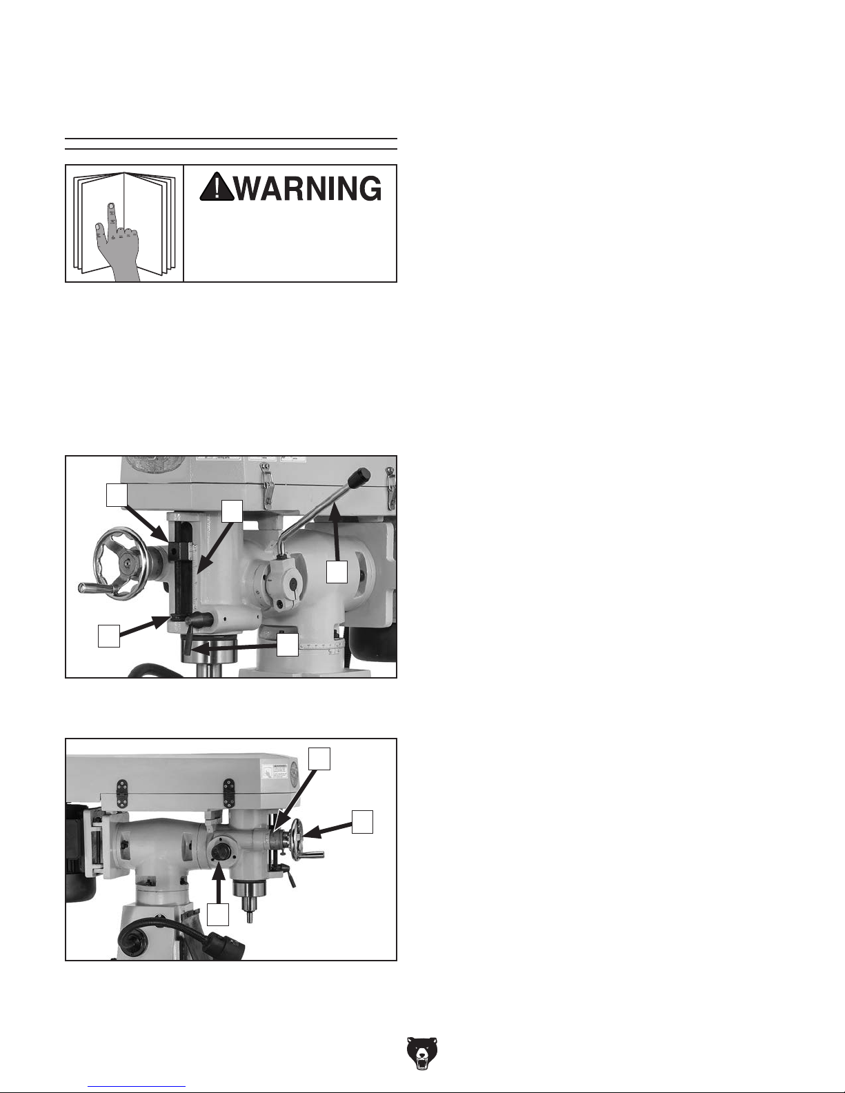
A. Quill Dog: Moves with the quill. Use the
pointer on the side with the downfeed scale
to determine the depth of downfeed travel.
B. Downfeed Scale: Displays the amount of
quill travel in inches.
C. Coarse Downfeed Lever: When this lever is
enabled with the downfeed selector, it raises/
lowers the quill quickly.
using machine.
Refer to Figures 1–2 and the following descriptions to become familiar with the basic controls
and components of this machine. Understanding
these items and how they work will help you
understand the rest of the manual and stay safe
when operating this machine.
Downfeed Controls
A
B
C
E
Figure 1. Downfeed controls viewed from the
right side.
D
D. Quill Lock Lever: Locks the quill in place but
does not affect spindle rotation.
E. Downfeed Stop & Lock Wheels: Stops the
downfeed travel when the quill dog reaches
this point. Set the stop wheel along the
downfeed scale for the desired depth of cut,
then secure it in place by tightening the lock
wheel.
F. Graduated Collar (Fine Downfeed):
Displays quill travel in 0.001" increments
when the fine downfeed handwheel is used.
One full revolution represents 0.100" of quill
travel.
G. Fine Downfeed Handwheel: When enabled,
it raises/lowers the quill in small increments.
H. Downfeed Selector: Enables either the
coarse or fine downfeed control. Tighten
the selector to enable the fine downfeed
handwheel, and loosen it to enable the
coarse downfeed lever.
H
Figure 2. Downfeed controls viewed from the left
side.
-4-
F
G
Model G0801/G0802 (Mfd. Since 09/15)
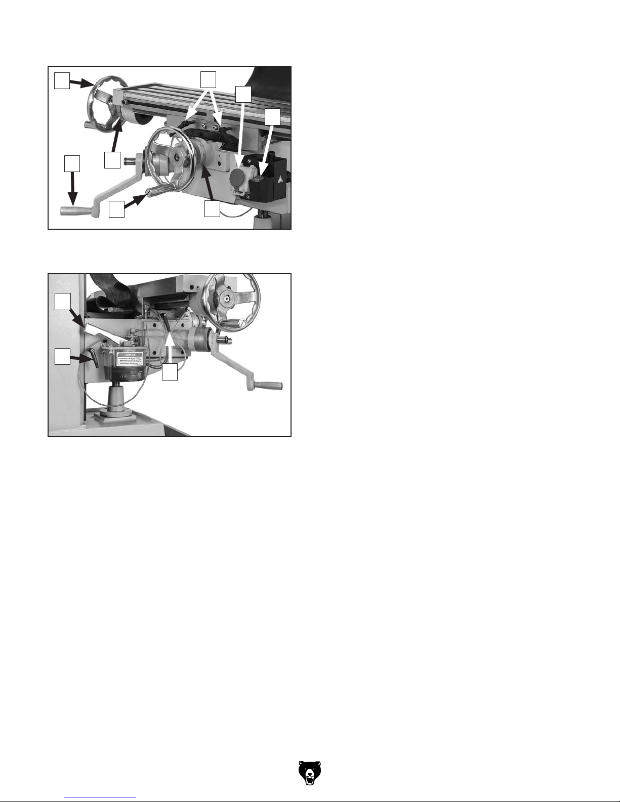
Table Controls
I
O
Figure 3. Table control handwheels and X-axis
Q
P
N
locks.
J
K
L
M
I. X-Axis Handwheel (1 of 2): Manually moves
table along X-axis (left and right).
J. X-Axis Locks: Tighten to prevent X-axis
table movement for increased rigidity during
operations when the X-axis should not move.
K. Power ON/OFF Switch: Turns machine ON
and OFF.
Note: Front panel of switch contains Stop
button only. Lift panel to access ON button,
then leave panel in "down" position during
use.
L. Spindle Direction Switch: Changes direc-
tion of spindle rotation.
M. Graduated Collar (Y-Axis): Displays Y-axis
table movement in 0.001" increments. One
full revolution represents 0.100" of table
travel.
R
S
Figure 4. Knee and cross slide locks, and one-
shot oiler.
N. Y-Axis Handwheel: Manually moves table
along Y-axis (front and back).
O. Knee Crank: Manually moves table along
Z-axis (up and down).
P. Graduated Collar (X-Axis): Displays X-axis
table movement in 0.001" increments. One
full revolution represents 0.100" of table
travel.
Q. One-Shot Oiler: Lubricates table ways.
R. Z-Axis Lock: Tightens to prevent Z-axis
table movement for increased rigidity during
operations when the Z-axis should not move.
S. Y-Axis Lock: Tightens to prevent Y-axis
table movement for increased rigidity during
operations when the Y-axis should not move.
Model G0801/G0802 (Mfd. Since 09/15)
-5-
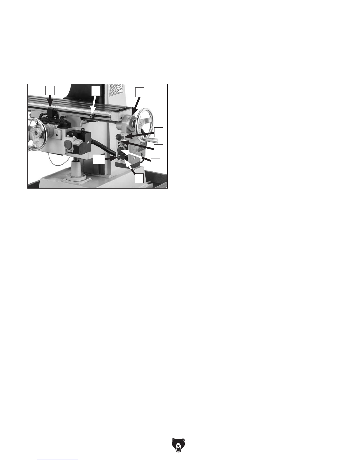
X-Axis Power Feed Controls (G0802)
Model G0802 is equipped with a power feed unit
for X-axis table movement. Refer to Figure 5 and
the following descriptions to understand the functions of the various components of the power feed
system.
T
U
V
W
T. Power Feed Limit Switch: Stops table
movement when either of the switch side
plungers are pressed by limit stops.
U. Limit Stop (1 of 2): Restricts table move-
ment by its positioning along front of table.
V. Graduated Collar (X-Axis): Displays dis-
tance of X-axis table travel in 0.001" increments. One full revolution equal to 0.100" of
table travel.
W. Rapid Traverse Button: When pressed,
moves table at full speed when already in
motion.
AA
Figure 5. Power feed controls.
X
Y
Z
X. Direction Lever: Selects direction of table
movement. Middle position is neutral.
Y. Speed Dial: Controls speed of table move-
ment. Turning dial clockwise causes table to
move faster.
Note: Feed rates for table travel are extreme-
ly difficult to precisely calculate. We recommend that you combine research and experimentation to find feed rates that best work for
your operations.
Z. ON/OFF Switch: Turns power feed ON and
OFF.
AA. Circuit Breaker Reset Button: Resets inter-
nal circuit breaker if unit is overloaded and
shuts down.
-6-
Model G0801/G0802 (Mfd. Since 09/15)

MACHINE DATA
SHEET
Customer Service #: (570) 546-9663 · To Order Call: (800) 523-4777 · Fax #: (800) 438-5901
MODEL G0801 6" X 26" VERTICAL MILL WITH LED
WORKLIGHT
Product Dimensions:
Weight.............................................................................................................................................................. 800 lbs.
Width (side-to-side) x Depth (front-to-back) x Height........................................................................... 45 x 41 x 68 in.
Footprint (Length x Width)............................................................................................................................ 21 x 28 in.
Space Required for Full Range of Movement (Width x Depth).............................................................. 59 x 39-1/2 in.
Shipping Dimensions:
Type.......................................................................................................................................................... Wood Crate
Content................................................................................................................................................. Machine/Stand
Weight.............................................................................................................................................................. 904 lbs.
Length x Width x Height....................................................................................................................... 40 x 37 x 74 in.
Must Ship Upright................................................................................................................................................... Yes
Electrical:
Power Requirement............................................................................................. 110V or 220V, Single-Phase, 60 Hz
Prewired Voltage.................................................................................................................................................. 110V
Full-Load Current Rating................................................................................................. 17.8A at 110V, 8.6A at 220V
Minimum Circuit Size.......................................................................................................... 20A at 110V, 15A at 220V
Connection Type....................................................................................................................................... Cord & Plug
Power Cord Included.............................................................................................................................................. Yes
Power Cord Length................................................................................................................................................. 6 ft.
Power Cord Gauge......................................................................................................................................... 14 AWG
Plug Included.......................................................................................................................................................... Yes
Included Plug Type................................................................................................................................. 5-15 for 110V
Recommended Plug Type...................................................................................................................... 6-15 for 220V
Switch Type.................................................................................................................... ON/OFF Push Button Switch
Motors:
Main
Horsepower............................................................................................................................................. 1.5 HP
Phase............................................................................................................................................ Single-Phase
Amps................................................................................................................................................. 17.8A/8.6A
Speed................................................................................................................................................ 1720 RPM
Type................................................................................................................. TEFC Capacitor-Start Induction
Power Transfer ............................................................................................................................... V-Belt Drive
Bearings..................................................................................................... Shielded & Permanently Lubricated
Centrifugal Switch/Contacts Type.......................................................................................................... Internal
Model G0801/G0802 (Mfd. Since 09/15)
-7-

Main Specifications:
Operation Info
Spindle Travel.............................................................................................................................................. 3 in.
Max Distance Spindle to Column.......................................................................................................... 5-1/4 in.
Max Distance Spindle to Table.................................................................................................................. 11 in.
Longitudinal Table Travel (X-Axis)...................................................................................................... 14-1/4 in.
Longitudinal Leadscrew (X-Axis)............................................................................................................... 36 in.
Cross Table Travel (Y-Axis)......................................................................................................................... 6 in.
Cross Leadscrew (Y-Axis)................................................................................................................... 14-3/4 in.
Vertical Table Travel (Z-Axis).................................................................................................................... 11 in.
Vertical Leadscrew (Z-Axis)....................................................................................................................... 17 in.
Turret or Column Swivel (Left /Right)..................................................................................................... 45 deg.
Head Tilt (Left/Right).............................................................................................................................. 45 deg.
Drilling Capacity for Cast Iron...................................................................................................................... 1 in.
Drilling Capacity for Steel......................................................................................................................... 3/4 in.
End Milling Capacity................................................................................................................................. 3/4 in.
Face Milling Capacity................................................................................................................................... 3 in.
Table Info
Table Length.............................................................................................................................................. 26 in.
Table Width........................................................................................................................................... 6-1/8 in.
Table Thickness.................................................................................................................................... 1-3/4 in.
Table Height (from Floor/Base)........................................................................................................... 17-3/4 in.
Number of T-Slots............................................................................................................................................ 3
T-Slot Size................................................................................................................................................ 1/2 in.
T-Slots Centers.................................................................................................................................. 1-11/16 in.
X/Y-Axis Travel per Handwheel Revolution.............................................................................................. 0.1 in.
Z-Axis Travel per Handwheel Revolution................................................................................................. 0.1 in.
Spindle Info
Spindle Taper............................................................................................................................................... R-8
Number of Vertical Spindle Speeds.................................................................................................................. 9
Range of Vertical Spindle Speeds........................................................................................... 230 – 2520 RPM
Quill Diameter....................................................................................................................................... 2.950 in.
Drawbar Thread Size....................................................................................................................... 7/16-20 TPI
Drawbar Length................................................................................................................................... 11-5/8 in.
Spindle Bearings......................................................................................................... Tapered Roller Bearings
Construction
Spindle Housing/Quill........................................................................................................................... Cast Iron
Table.................................................................................................................................................... Cast Iron
Head.................................................................................................................................................... Cast Iron
Column/Base....................................................................................................................................... Cast Iron
Base..................................................................................................................................................... Cast Iron
Stand.......................................................................................................................................................... Steel
Paint Type/Finish...................................................................................................................................... Epoxy
Other Specifications:
Country of Origin ................................................................................................................................................ China
Warranty ........................................................................................................................................................... 1 Year
Approximate Assembly & Setup Time .............................................................................................................. 1 Hour
Serial Number Location .................................................................................................................................. ID Label
ISO 9001 Factory .................................................................................................................................................. Yes
Certified by a Nationally Recognized Testing Laboratory (NRTL) .......................................................................... No
-8-
Model G0801/G0802 (Mfd. Since 09/15)

MACHINE DATA
SHEET
Customer Service #: (570) 546-9663 · To Order Call: (800) 523-4777 · Fax #: (800) 438-5901
MODEL G0802 6" X 26" VERTICAL MILL WITH POWER FEED
AND LED WORKLIGHT
Product Dimensions:
Weight.............................................................................................................................................................. 810 lbs.
Width (side-to-side) x Depth (front-to-back) x Height........................................................................... 45 x 41 x 68 in.
Footprint (Length x Width)............................................................................................................................ 21 x 28 in.
Space Required for Full Range of Movement (Width x Depth).............................................................. 59 x 39-1/2 in.
Shipping Dimensions:
Type.......................................................................................................................................................... Wood Crate
Content................................................................................................................................................. Machine/Stand
Weight.............................................................................................................................................................. 914 lbs.
Length x Width x Height....................................................................................................................... 40 x 37 x 74 in.
Must Ship Upright................................................................................................................................................... Yes
Electrical:
Power Requirement............................................................................................. 110V or 220V, Single-Phase, 60 Hz
Prewired Voltage.................................................................................................................................................. 110V
Full-Load Current Rating................................................................................................. 17.8A at 110V, 8.6A at 220V
Minimum Circuit Size.......................................................................................................... 20A at 110V, 15A at 220V
Connection Type....................................................................................................................................... Cord & Plug
Power Cord Included.............................................................................................................................................. Yes
Power Cord Length................................................................................................................................................. 6 ft.
Power Cord Gauge......................................................................................................................................... 14 AWG
Plug Included.......................................................................................................................................................... Yes
Included Plug Type................................................................................................................................. 5-15 for 110V
Recommended Plug Type...................................................................................................................... 6-15 for 220V
Switch Type.................................................................................................................... ON/OFF Push Button Switch
Motors:
Main
Horsepower............................................................................................................................................. 1.5 HP
Phase............................................................................................................................................ Single-Phase
Amps................................................................................................................................................. 17.8A/8.6A
Speed................................................................................................................................................ 1720 RPM
Type................................................................................................................. TEFC Capacitor-Start Induction
Power Transfer ............................................................................................................................... V-Belt Drive
Bearings..................................................................................................... Shielded & Permanently Lubricated
Centrifugal Switch/Contacts Type.......................................................................................................... Internal
Model G0801/G0802 (Mfd. Since 09/15)
-9-

Main Specifications:
Operation Info
Spindle Travel.............................................................................................................................................. 3 in.
Max Distance Spindle to Column.......................................................................................................... 5-1/4 in.
Max Distance Spindle to Table.................................................................................................................. 11 in.
Longitudinal Table Travel (X-Axis)...................................................................................................... 14-1/4 in.
Longitudinal Leadscrew (X-Axis)............................................................................................................... 36 in.
Cross Table Travel (Y-Axis)......................................................................................................................... 6 in.
Cross Leadscrew (Y-Axis)................................................................................................................... 14-3/4 in.
Vertical Table Travel (Z-Axis).................................................................................................................... 11 in.
Vertical Leadscrew (Z-Axis)....................................................................................................................... 17 in.
Turret or Column Swivel (Left /Right)..................................................................................................... 45 deg.
Head Tilt (Left/Right).............................................................................................................................. 45 deg.
Drilling Capacity for Cast Iron...................................................................................................................... 1 in.
Drilling Capacity for Steel......................................................................................................................... 3/4 in.
End Milling Capacity................................................................................................................................. 3/4 in.
Face Milling Capacity................................................................................................................................... 3 in.
Table Info
Table Length.............................................................................................................................................. 26 in.
Table Width........................................................................................................................................... 6-1/8 in.
Table Thickness.................................................................................................................................... 1-3/4 in.
Table Height (from Floor/Base)........................................................................................................... 17-3/4 in.
Number of T-Slots............................................................................................................................................ 3
T-Slot Size................................................................................................................................................ 1/2 in.
T-Slots Centers...................................................................................................................................... 1-5/8 in.
X-Axis Table Power Feed Rate................................................................................................... 0 – 3-3/8 FPM
X/Y-Axis Travel per Handwheel Revolution.............................................................................................. 0.1 in.
Z-Axis Travel per Handwheel Revolution................................................................................................. 0.1 in.
Spindle Info
Spindle Taper............................................................................................................................................... R-8
Number of Vertical Spindle Speeds.................................................................................................................. 9
Range of Vertical Spindle Speeds........................................................................................... 230 – 2520 RPM
Quill Diameter....................................................................................................................................... 2.950 in.
Drawbar Thread Size....................................................................................................................... 7/16-20 TPI
Drawbar Length................................................................................................................................... 11-5/8 in.
Spindle Bearings......................................................................................................... Tapered Roller Bearings
Construction
Spindle Housing/Quill........................................................................................................................... Cast Iron
Table.................................................................................................................................................... Cast Iron
Head.................................................................................................................................................... Cast Iron
Column/Base....................................................................................................................................... Cast Iron
Base..................................................................................................................................................... Cast Iron
Stand.......................................................................................................................................................... Steel
Paint Type/Finish...................................................................................................................................... Epoxy
Other Specifications:
Country of Origin ................................................................................................................................................ China
Warranty .......................................................................................................................................................... 1 Year
Approximate Assembly & Setup Time .............................................................................................................. 1 Hour
Serial Number Location .................................................................................................................................. ID Label
ISO 9001 Factory .................................................................................................................................................. Yes
Certified by a Nationally Recognized Testing Laboratory (NRTL) .......................................................................... No
-10 -
Model G0801/G0802 (Mfd. Since 09/15)
SECTION 1: SAFETY
For Your Own Safety, Read Instruction
Manual Before Operating This Machine
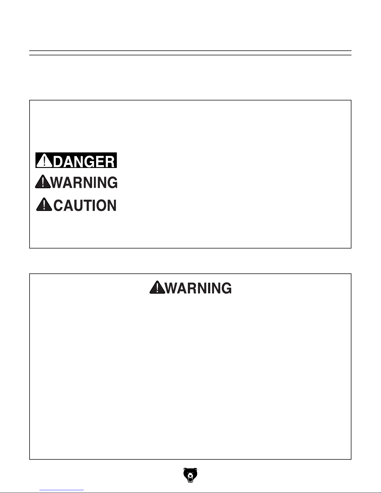
The purpose of safety symbols is to attract your attention to possible hazardous conditions.
This manual uses a series of symbols and signal words intended to convey the level of importance of the safety messages. The progression of symbols is described below. Remember that
safety messages by themselves do not eliminate danger and are not a substitute for proper
accident prevention measures. Always use common sense and good judgment.
Indicates an imminently hazardous situation which, if not avoided,
WILL result in death or serious injury.
Indicates a potentially hazardous situation which, if not avoided,
COULD result in death or serious injury.
Indicates a potentially hazardous situation which, if not avoided,
MAY result in minor or moderate injury. It may also be used to alert
against unsafe practices.
This symbol is used to alert the user to useful information about
NOTICE
proper operation of the machine.
Safety Instructions for Machinery
OWNER’S MANUAL. Read and understand this
owner’s manual BEFORE using machine.
TRAINED OPERATORS ONLY. Untrained operators have a higher risk of being hurt or killed.
Only allow trained/supervised people to use this
machine. When machine is not being used, disconnect power, remove switch keys, or lock-out
machine to prevent unauthorized use—especially
around children. Make your workshop kid proof!
DANGEROUS ENVIRONMENTS. Do not use
machinery in areas that are wet, cluttered, or have
poor lighting. Operating machinery in these areas
greatly increases the risk of accidents and injury.
MENTAL ALERTNESS REQUIRED. Full mental
alertness is required for safe operation of machinery. Never operate under the influence of drugs or
alcohol, when tired, or when distracted.
ELECTRICAL EQUIPMENT INJURY RISKS. You
can be shocked, burned, or killed by touching live
electrical components or improperly grounded
machinery. To reduce this risk, only allow qualified
service personnel to do electrical installation or
repair work, and always disconnect power before
accessing or exposing electrical equipment.
DISCONNECT POWER FIRST.
nect machine from power supply BEFORE making
adjustments, changing tooling, or servicing machine.
This prevents an injury risk from unintended startup
or contact with live electrical components.
EYE PROTECTION. Always wear ANSI-approved
safety glasses or a face shield when operating or
observing machinery to reduce the risk of eye
injury or blindness from flying particles. Everyday
eyeglasses are NOT approved safety glasses.
Always discon-
Model G0801/G0802 (Mfd. Since 09/15)
-11-

WEARING PROPER APPAREL. Do not wear
clothing, apparel or jewelry that can become
entangled in moving parts. Always tie back or
cover long hair. Wear non-slip footwear to reduce
risk of slipping and losing control or accidentally
contacting cutting tool or moving parts.
HAZARDOUS DUST. Dust created by machinery
operations may cause cancer, birth defects, or
long-term respiratory damage. Be aware of dust
hazards associated with each workpiece material. Always wear a NIOSH-approved respirator to
reduce your risk.
HEARING PROTECTION. Always wear hearing protection when operating or observing loud
machinery. Extended exposure to this noise
without hearing protection can cause permanent
hearing loss.
REMOVE ADJUSTING TOOLS. Tools left on
machinery can become dangerous projectiles
upon startup. Never leave chuck keys, wrenches,
or any other tools on machine. Always verify
removal before starting!
USE CORRECT TOOL FOR THE JOB. Only use
this tool for its intended purpose—do not force
it or an attachment to do a job for which it was
not designed. Never make unapproved modifications—modifying tool or using it differently than
intended may result in malfunction or mechanical
failure that can lead to personal injury or death!
AWKWARD POSITIONS. Keep proper footing
and balance at all times when operating machine.
Do not overreach! Avoid awkward hand positions
that make workpiece control difficult or increase
the risk of accidental injury.
CHILDREN & BYSTANDERS. Keep children and
bystanders at a safe distance from the work area.
Stop using machine if they become a distraction.
GUARDS & COVERS. Guards and covers reduce
accidental contact with moving parts or flying
debris. Make sure they are properly installed,
undamaged, and working correctly BEFORE
operating machine.
FORCING MACHINERY. Do not force machine.
It will do the job safer and better at the rate for
which it was designed.
NEVER STAND ON MACHINE. Serious injury
may occur if machine is tipped or if the cutting
tool is unintentionally contacted.
STABLE MACHINE. Unexpected movement during operation greatly increases risk of injury or
loss of control. Before starting, verify machine is
stable and mobile base (if used) is locked.
USE RECOMMENDED ACCESSORIES. Consult
this owner’s manual or the manufacturer for recommended accessories. Using improper accessories will increase the risk of serious injury.
UNATTENDED OPERATION. To reduce the
risk of accidental injury, turn machine OFF and
ensure all moving parts completely stop before
walking away. Never leave machine running
while unattended.
MAINTAIN WITH CARE. Follow all maintenance
instructions and lubrication schedules to keep
machine in good working condition. A machine
that is improperly maintained could malfunction,
leading to serious personal injury or death.
DAMAGED PARTS. Regularly inspect machine
for damaged, loose, or mis-adjusted parts—or
any condition that could affect safe operation.
Immediately repair/replace BEFORE operating
machine. For your own safety, DO NOT operate
machine with damaged parts!
MAINTAIN POWER CORDS. When disconnecting cord-connected machines from power, grab
and pull the plug—NOT the cord. Pulling the cord
may damage the wires inside. Do not handle
cord/plug with wet hands. Avoid cord damage by
keeping it away from heated surfaces, high traffic
areas, harsh chemicals, and wet/damp locations.
EXPERIENCING DIFFICULTIES. If at any time
you experience difficulties performing the intended operation, stop using the machine! Contact our
Technical Support at (570) 546-9663.
-12-
Model G0801/G0802 (Mfd. Since 09/15)

Additional Safety for Mills
You can be seriously injured or killed by getting clothing, jewelry, or long hair entangled with
rotating cutter/spindle. You can be severely cut or have fingers amputated from contact with
rotating cutters. You can be blinded or struck by broken cutting tools, metal chips, workpieces,
or adjustment tools thrown from the rotating spindle with great force. To reduce your risk of
serious injury when operating this machine, completely heed and understand the following:
UNDERSTAND ALL CONTROLS. Make sure
you understand the function and proper use of all
controls before starting. This will help you avoid
making mistakes that result in serious injury.
AVOIDING ENTANGLEMENT. DO NOT wear
loose clothing, gloves, or jewelry, and tie back
long hair. Keep all guards in place and secure.
Always allow spindle to stop on its own. DO NOT
stop spindle using your hand or any other object.
WEAR FACE SHIELD. Always wear a face shield
in addition to safety glasses. This provides more
complete protection for your face than safety
glasses alone.
USE CORRECT SPINDLE SPEED. Follow recommended speeds and feeds for each size and
type of cutting tool. This helps avoid tool breakage
during operation and ensures best cutting results.
INSPECT CUTTING TOOL. Inspect cutting tools
for sharpness, chips, or cracks before each use.
Replace dull, chipped, or cracked cutting tools
immediately.
PROPERLY SECURE CUTTER. Firmly secure
cutting tool or drill bit so it does not fly out of spindle during operation.
POWER DISRUPTION. In the event of a local
power outage during operation, turn spindle
switch OFF to avoid a possible sudden startup
once power is restored.
CLEAN MACHINE SAFELY. Metal chips or shavings can be razor sharp. DO NOT clear chips
by hand or compressed air that can force chips
farther into machine—use a brush or vacuum
instead. Never clear chips while spindle is turning.
SECURE WORKPIECE TO TABLE. Clamp workpiece to table or secure in a vise mounted to table,
so workpiece cannot unexpectedly shift or spin
during operation. NEVER hold workpiece by hand
during operation.
PROPERLY MAINTAIN MACHINE. Keep
machine in proper working condition to help
ensure that it functions safely and all guards and
other components work as intended. Perform routine inspections and all necessary maintenance.
Never operate machine with damaged or worn
parts that can break or result in unexpected movement during operation.
DISCONNECT POWER FIRST. To reduce risk of
electrocution or injury from unexpected startup,
make sure mill/drill is turned OFF, disconnected
from power, and all moving parts have come to
a complete stop before changing cutting tools or
starting any inspection, adjustment, or maintenance procedure.
REMOVE CHUCK KEY & SPINDLE TOOLS.
Always remove chuck key, drawbar wrench, and
other tools used on the spindle immediately after
use. This will prevent them from being thrown by
the spindle upon startup.
Model G0801/G0802 (Mfd. Since 09/15)
-13-

SECTION 2: POWER SUPPLY
Before installing the machine, consider the availability and proximity of the required power supply
circuit. If an existing circuit does not meet the
requirements for this machine, a new circuit must
be installed. To minimize the risk of electrocution,
fire, or equipment damage, installation work and
electrical wiring must be done by an electrician or
qualified service personnel in accordance with all
applicable codes and standards.
or equipment damage
may occur if machine is
not properly grounded
and connected to power
The full-load current rating is the amperage a
machine draws at 100% of the rated output power.
On machines with multiple motors, this is the
amperage drawn by the largest motor or sum of all
motors and electrical devices that might operate
at one time during normal operations.
The full-load current is not the maximum amount
of amps that the machine will draw. If the machine
is overloaded, it will draw additional amps beyond
the full-load rating.
If the machine is overloaded for a sufficient length
of time, damage, overheating, or fire may result—
especially if connected to an undersized circuit.
To reduce the risk of these hazards, avoid overloading the machine during operation and make
sure it is connected to a power supply circuit that
meets the specified circuit requirements.
For your own safety and protection of
Note: Circuit requirements in this manual apply to
a dedicated circuit—where only one machine will
be running on the circuit at a time. If machine will
be connected to a shared circuit where multiple
machines may be running at the same time, consult an electrician or qualified service personnel to
ensure circuit is properly sized for safe operation.
A power supply circuit includes all electrical
equipment between the breaker box or fuse panel
in the building and the machine. The power supply circuit used for this machine must be sized to
safely handle the full-load current drawn from the
machine for an extended period of time. (If this
machine is connected to a circuit protected by
fuses, use a time delay fuse marked D.)
This machine can be converted to operate on a
power supply circuit that has a verified ground
and meets the requirements listed below. (Refer
to Voltage Conversion instructions for details.)
This machine is prewired to operate on a power
supply circuit that has a verified ground and meets
the following requirements:
Availability
Electrocution, fire, shock,
supply.
Full-Load Current Rating
Circuit Information
property, consult an electrician if you are
unsure about wiring practices or electrical
codes in your area.
Full-Load Current Rating at 110V ....17.8 Amps
Full-Load Current Rating at 220V .... 8.6 Amps
-14-
Circuit Requirements for 110V
Nominal Voltage .................... 110V, 115V, 120V
Cycle ..........................................................60 Hz
Phase ........................................... Single-Phase
Power Supply Circuit ......................... 20 Amps
Plug/Receptacle ............................. NEMA 5-15
Circuit Requirements for 220V
Nominal Voltage .........208V, 22 0V, 2 30V, 240V
Cycle ..........................................................60 Hz
Phase ........................................... Single-Phase
Power Supply Circuit ......................... 15 Amps
Plug/Receptacle ............................. NEMA 6 -15
Model G0801/G0802 (Mfd. Since 09/15)
Improper connection of the equipment-grounding
wire can result in a risk of electric shock. The
wire with green insulation (with or without yellow
stripes) is the equipment-grounding wire. If repair
or replacement of the power cord or plug is necessary, do not connect the equipment-grounding
wire to a live (current carrying) terminal.
Check with a qualified electrician or service personnel if you do not understand these grounding
requirements, or if you are in doubt about whether
the tool is properly grounded. If you ever notice
that a cord or plug is damaged or worn, disconnect it from power, and immediately replace it with
a new one.
We do not recommend using an extension cord
with this machine.
cord, only use it if absolutely necessary and only
on a temporary basis.
Extension cords cause voltage drop, which can
damage electrical components and shorten motor
life. Voltage drop increases as the extension cord
size gets longer and the gauge size gets smaller
(higher gauge numbers indicate smaller sizes).
Any extension cord used with this machine must
be in good condition and contain a ground wire
and matching plug/receptacle. Additionally, it must
meet the following size requirements:
Grounding Requirements
This machine MUST be grounded. In the event
of certain malfunctions or breakdowns, grounding
reduces the risk of electric shock by providing a
path of least resistance for electric current.
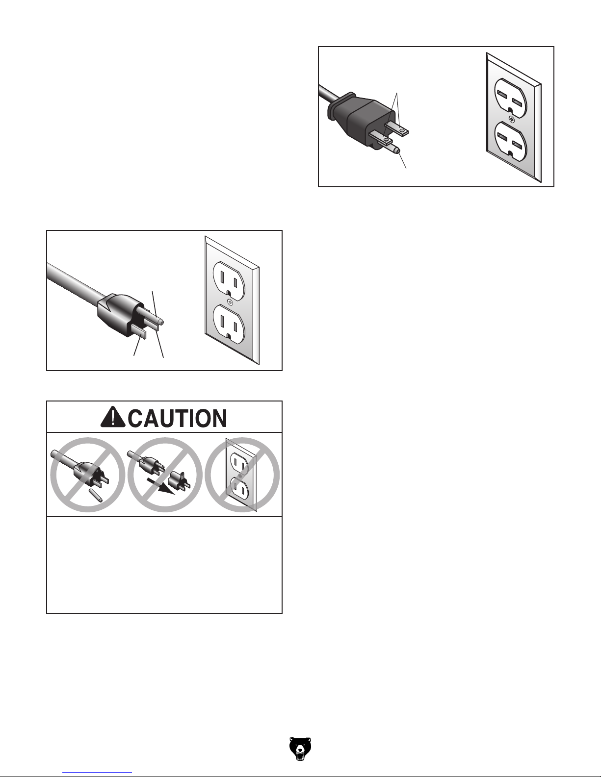
For 110V operation: This machine is equipped
with a power cord that has an equipment-grounding wire and a grounding plug (see following figure). The plug must only be inserted into a matching receptacle (outlet) that is properly installed
and grounded in accordance with all local codes
and ordinances.
For 220V operation: The plug specified under
“
page has a grounding prong that must be attached
to the equipment-grounding wire on the included
power cord. The plug must only be inserted into
a matching receptacle (see following figure) that
is properly installed and grounded in accordance
with all local codes and ordinances.
it will not fit the outlet, have a qualified
electrician install the proper outlet with a
GROUNDED
5-15 RECEPTACLE
Grounding Prong
GROUNDED
6-15 RECEPTACLE
Current Carrying Prongs
6-15 PLUG
Grounding Prong
Figure 7. Typical 6-15 plug and receptacle.
5-15 PLUG
Neutral Hot
Figure 6. Typical 5-15 plug and receptacle.
SHOCK HAZARD!
Two-prong outlets do not meet the grounding
requirements for this machine. Do not modify
or use an adapter on the plug provided—if
verified ground.
Circuit Requirements for 220V” on the previous
Model G0801/G0802 (Mfd. Since 09/15)
Extension Cords
If you must use an extension
Minimum Gauge Size (G0801) .............12 AWG
Minimum Gauge Size (G0802) ............14 AWG
Maximum Length (Shorter is Better).......50 ft.
-15-
Converting Voltage
to 220V
Tip: Although it is only necessary to install
one jumper across middle terminals, installing both jumpers here prevents misplacing
the extra one in case you need it later to convert machine back to 110V.
The voltage conversion MUST be performed by
an electrician or qualified service personnel. The
voltage conversion procedure consists of rewiring
the motor and transformer, and installing the correct plug. Wiring diagrams are provided on Pages
54–54 for your reference.
IMPORTANT: If the diagram included on the
motor conflicts with those on Pages 54–54, the
motor may have changed since the manual was
printed. Use the diagram included on the motor
instead.
Tools Needed: Qty
• Phillips Head Screwdriver #2 ..................... 1
• Plug 6-15 .................................................... 1
• Wire Cutters/Stripper .................................. 1
To convert machine to 220V:
1. DISCONNECT MACHINE FROM POWER!
2. Remove 110V switch and replace with 220V
switch (P0801405).
6. Re-install motor junction box cover.
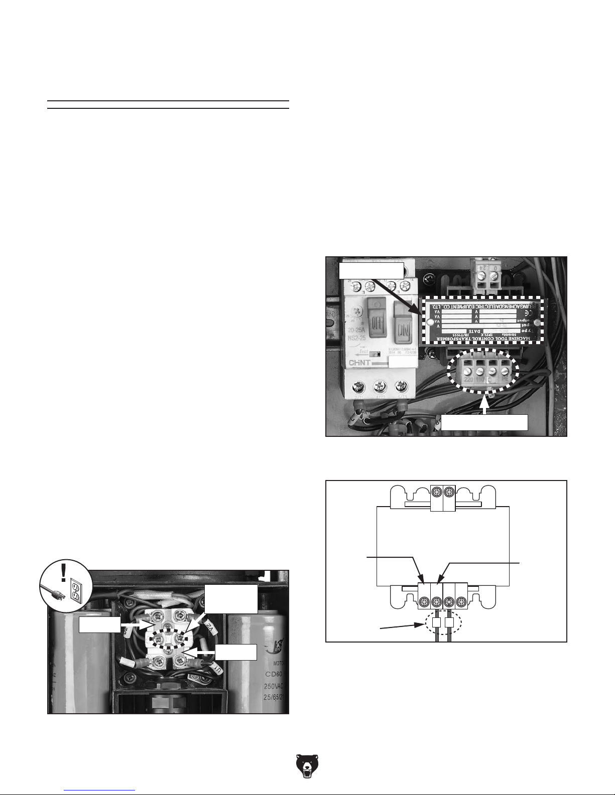
7. Remove electrical panel access cover, then
locate transformer lower terminals and two
wires marked "L" and "N" (see Figures
9–10), then disconnect wire from 110V terminal and connect it to 220V terminal.
Note: DO NOT move wire marked "N."
Transformer
Lower Terminals
3. Cut off existing 5-15 plug.
4. Remove motor junction box cover, then
remove two jumpers, shown in Figure 8.
5. Stack both jumpers and install them across
middle terminals, (see Figure 8), then make
sure all wires are securely installed in same
locations as they were when you started.
Middle
Terminals
Jumper
Jumper
Figure 8. Location of jumpers and middle
terminals inside motor junction box.
Figure 9. Location of transformer lower
terminals.
024
TRANSFORMER
JBK5-63VA
INPUT: 100-220
220V
Terminal
Wires
OUTPUT: 24
0220 110 PE
L
N
110V
Terminal
Figure 10. Transformer wired for 110V.
8. Re-install electrical panel access cover.
9. Install a 6-15 plug on the power cord, accord-
ing to the plug manufacturer's instructions. If
the plug manufacturer's instructions are not
available.
-16 -
Model G0801/G0802 (Mfd. Since 09/15)
SECTION 3: SETUP
This machine was carefully packaged for safe
transport. When unpacking, separate all enclosed
items from packaging materials and inspect them
for shipping damage.
,
please
IMPORTANT:
you are completely satisfied with the machine and
have resolved any issues between Grizzly or the
shipping agent. You MUST have the original pack-
aging to file a freight claim. It is also extremely
helpful if you need to return your machine later.
Keep children and pets away
from plastic bags or packing
materials shipped with this
get help from other people
The following items are needed, but not included,
for the setup/assembly of this machine.
Needed for Setup
This machine presents
serious injury hazards
to untrained users. Read
through this entire manual to become familiar with
the controls and operations before starting the
machine!
Wear safety glasses during
the entire setup process!
Description Qty
• Precision Level ........................................... 1
• Safety Glasses (for each person) ............... 1
• Solvent/Degreaser (see Page 19) .............. 1
• Disposable Rags ........................ As Needed
• Brass Hammer ........................................... 1
• Lifting Straps
(Rated for at least 1000 lbs.) ...................... 2
• Forklift or Lifting Equipment
(Rated for at least 1000 lbs.) ...................... 1
• Lifting Bar
• Another Person .......................................... 1
3
⁄4" Dia. x 36" L .......................... 1
HEAV Y LI FT!
Straining or crushing injury
may occur from improperly
lifting machine or some of
its parts. To reduce this risk,
and use a forklift (or other
lifting equipment) rated for
weight of this machine.
Unpacking
If items are damaged
call us immediately at (570) 546-9663.
Save all packaging materials until
SUFFOCATION HAZARD!
machine. Discard immediately.
Model G0801/G0802 (Mfd. Since 09/15)
-17-
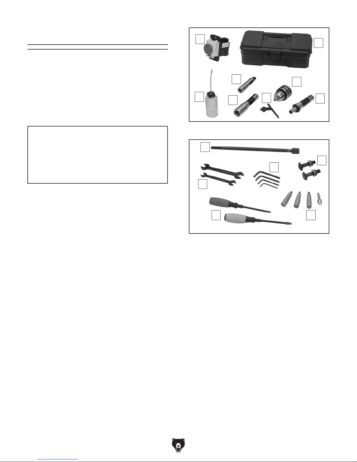
Inventory
The following is a list of items shipped with your
machine. Before beginning setup, lay these items
out and inventory them.
If any non-proprietary parts are missing (e.g. a
nut or a washer), we will gladly replace them; or
for the sake of expediency, replacements can be
obtained at your local hardware store.
A
B
NOTICE
If you cannot find an item on this list, carefully check around/inside the machine and
packaging materials. Often, these items get
lost in packaging materials while unpacking or they are pre-installed at the factory.
Small Item Inventory (Figures 11–12) Qty
A. Power ON/OFF Switch 220V ...................... 1
B. Toolbox ....................................................... 1
C. Bottle for Oil ............................................... 1
D. Spindle Sleeve MT#3 x MT#2 .................... 1
E. Spindle Sleeve R-8 x MT#3 ....................... 1
F. Chuck Key .................................................. 1
G. Drill Chuck B16 1–13mm ............................ 1
H. Drill Chuck Arbor R-8/B16 .......................... 1
l. Drawbar
J. Open-End Wrenches
12/14mm & 17/19mm ............................1 Ea.
K. Hex Wrenches 3, 4, 5, 6mm .................1 Ea.
L. T-Bolts M12-1.75 x 55
w/Hex Nuts & Flat Washers ....................... 2
M. Screwdrivers Standard & Phillips #2 ....1 Ea.
N. Handwheel Handles ................................... 4
7
⁄16"-20 .......................................... 1
D
C
Figure 11. Large item inventory.
I
J
Figure 12. Small item inventory.
E
M N
F
K
G
H
L
-18-
Model G0801/G0802 (Mfd. Since 09/15)
The unpainted surfaces of your machine are
coated with a heavy-duty rust preventative that
prevents corrosion during shipment and storage.
This rust preventative works extremely well, but it
will take a little time to clean.
Be patient and do a thorough job cleaning your
machine. The time you spend doing this now will
give you a better appreciation for the proper care
of your machine's unpainted surfaces.
There are many ways to remove this rust preventative, but the following steps work well in a wide
variety of situations. Always follow the manufacturer’s instructions with any cleaning product you
use and make sure you work in a well-ventilated
area to minimize exposure to toxic fumes.
Before cleaning, gather the following:
• Disposable rags
• Cleaner/degreaser (WD•40 works well)
• Safety glasses & disposable gloves
• Plastic paint scraper (optional)
Basic steps for removing rust preventative:
1.
2.
3.
4.
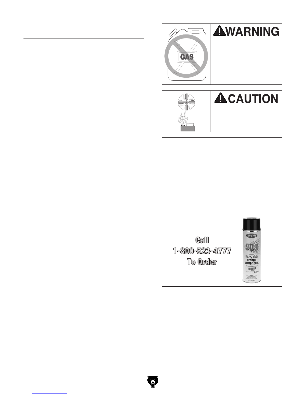
Many cleaning solvents
work in a well-ventilated
Avoid chlorine-based solvents, such as
Cleanup
Gasoline and petroleum
products have low flash
points and can explode
or cause fire if used to
clean machinery. Avo i d
using these products
to clean machinery.
Put on safety glasses.
Coat the rust preventative with a liberal
amount of cleaner/degreaser, then let it soak
for 5–10 minutes.
Wipe off the surfaces. If your cleaner/degreas-
er is effective, the rust preventative will wipe
off easily. If you have a plastic paint scraper,
scrape off as much as you can first, then wipe
off the rest with the rag.
Repeat Steps 2–3 as necessary until clean,
then coat all unpainted surfaces with a quality
metal protectant to prevent rust.
are toxic if inhaled. Only
area.
NOTICE
acetone or brake parts cleaner, that may
damage painted surfaces.
T23692—Orange Power Degreaser
A great product for removing the waxy shipping grease from the non-painted parts of the
machine during clean up.
Figure 13. T23692 Orange Power Degreaser.
Model G0801/G0802 (Mfd. Since 09/15)
-19 -
 Loading...