

Grizzly G0799, G0800 Owner's Manual

MODELS G0799 & G0800
20" & 24" VARIABLE-SPEED
WOOD LATHES
OWNER'S MANUAL
COPYRIGHT © MARCH, 2016 BY GRIZZLY INDUSTRIAL, INC.
WARNING: NO PORTION OF THIS MANUAL MAY BE REPRODUCED IN ANY SHAPE
OR FORM WITHOUT THE WRITTEN APPROVAL OF GRIZZLY INDUSTRIAL, INC.
#MN17816 PRINTED IN CHINA
V1. 0 6.16

This manual provides critical safety instructions on the proper setup,
operation, maintenance, and service of this machine/tool. Save this
document, refer to it often, and use it to instruct other operators.
Failure to read, understand and follow the instructions in this manual
may result in fire or serious personal injury—including amputation,
electrocution, or death.
The owner of this machine/tool is solely responsible for its safe use.
This responsibility includes but is not limited to proper installation in
a safe environment, personnel training and usage authorization,
proper inspection and maintenance, manual availability and comprehension, application of safety devices, cutting/sanding/grinding tool
integrity, and the usage of personal protective equipment.
The manufacturer will not be held liable for injury or property damage
from negligence, improper training, machine modifications or misuse.
Some dust created by power sanding, sawing, grinding, drilling, and
other construction activities contains chemicals known to the State
of California to cause cancer, birth defects or other reproductive
harm. Some examples of these chemicals are:
• Lead from lead-based paints.
• Crystalline silica from bricks, cement and other masonry products.
• Arsenic and chromium from chemically-treated lumber.
Your risk from these exposures varies, depending on how often you
do this type of work. To reduce your exposure to these chemicals:
Work in a well ventilated area, and work with approved safety equipment, such as those dust masks that are specially designed to filter
out microscopic particles.

Table of Contents
INTRODUCTION ............................................... 2
Contact Info.................................................... 2
Manual Accuracy ........................................... 2
Identification ................................................... 3
Controls & Components ................................. 4
Glossary Of Terms ......................................... 6
G0799 Machine Data Sheet .......................... 7
G0800 Machine Data Sheet .......................... 9
SECTION 1: SAFETY ..................................... 11
Safety Instructions for Machinery ................ 11
Additional Safety for Wood Lathes .............. 13
SECTION 2: POWER SUPPLY ...................... 14
SECTION 3: SETUP ....................................... 16
Needed for Setup ......................................... 16
Unpacking .................................................... 16
Hardware Recognition Chart ....................... 17
Inventory ...................................................... 18
Cleanup ........................................................ 20
Site Considerations ...................................... 21
Assembly ..................................................... 22
Test Run ...................................................... 26
Anchoring to Floor ....................................... 27
SECTION 5: ACCESSORIES ......................... 43
SECTION 6: MAINTENANCE ......................... 45
Schedule ...................................................... 45
Cleaning & Protecting .................................. 45
Lubrication ................................................... 45
SECTION 7: SERVICE ................................... 46
Troubleshooting ........................................... 46
Tensioning/Replacing Belt ........................... 48
Aligning Pulleys............................................ 49
Removing End Play ..................................... 50
SECTION 8: WIRING ...................................... 51
Wiring Safety Instructions ............................ 51
G0799 & G0800 Electrical Components ...... 52
G0799 & G0800 Wiring Diagram ................. 53
SECTION 9: PARTS ....................................... 54
Main ............................................................. 54
Headstock .................................................... 56
Labels .......................................................... 58
WARRANTY & RETURNS ............................. 61
SECTION 4: OPERATIONS ........................... 28
Operation Overview ..................................... 28
Workpiece Inspection................................... 29
Adjusting Headstock .................................... 29
Adjusting Tailstock ....................................... 30
Adjusting Tool Rest ...................................... 30
Installing/Removing Headstock Center ........ 32
Installing/Removing Tailstock Center .......... 33
Installing Faceplate ...................................... 34
Changing Speed Ranges ............................. 35
Indexing ....................................................... 36
Spindle Turning ............................................ 37
Faceplate Turning ........................................ 39
Outboard Turning ......................................... 40
Sanding/Finishing ........................................ 41
Selecting Turning Tools ............................... 42

INTRODUCTION
We are proud to provide a high-quality owner’s
manual with your new machine!
We
instructions, specifications, drawings, and photographs
in this manual. Sometimes we make mistakes, but
our policy of continuous improvement also means
that
you receive is
slightly different than shown in the manual
If you find this to be the case, and the difference
between the manual and machine leaves you
confused or unsure about something
check our
website for an updated version. W
current
manuals and
on our web-
site at
Alternatively, you can call our Technical Support
for help. Before calling, make sure you write down
the
from
the machine ID label (see below). This information
is required for us to provide proper tech support,
and it helps us determine if updated documentation is available for your machine.
We stand behind our machines! If you have questions or need help, contact us with the information
below. Before contacting, make sure you get the
serial number
machine ID label. This will help us help you faster.
We want your feedback on this manual. What did
you like about it? Where could it be improved?
Please take a few minutes to give us feedback.
Email: manuals@grizzly.com
Contact Info
and manufacture date from the
Grizzly Technical Support
1815 W. Battlefield
Springfield, MO 65807
Phone: (570) 546-9663
Email: techsupport@grizzly.com
Grizzly Documentation Manager
P.O. Box 2069
Bellingham, WA 98227-2069
Manual Accuracy
made every effort to be exact with the
sometimes the machine
.
,
e post
manual updates for free
www.grizzly.com.
Manufacture Date and Serial Number
Manufacture Date
Serial Number
-2-
Model G0799 G0800 (Mfd. Since 09/15)
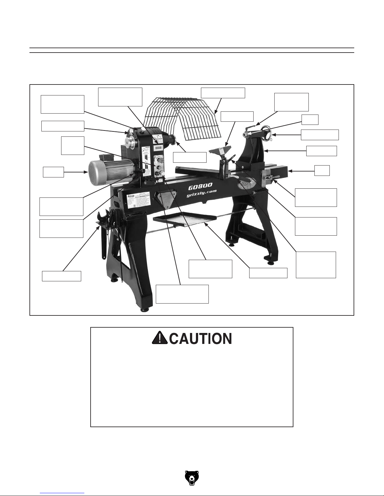
Identification
Become familiar with the names and locations of the controls and features shown below to better understand
the instructions in this manual.
Belt Access
Cover
Spindle Lock
Reset
Button
Motor
Belt Tension
Lock Handle
Belt Tension
Lever
Tool Holder
Spindle RPM
Readout
Faceplate
Control Knob
Chuck Guard
Tool Rest
Speed
Quill Lock
Chisel Tray
Lever
Quill
Handwheel
Tailstock
Bed
Swing-Away
Bed Latch
Tool Rest
Lock Handle
Tool Rest
Base
Lock Lever
Spindle
Direction Switch
For Your Own Safety Read Instruction Manual Before
Operating Lathe
a) Wear eye protection.
b) Do not wear gloves, necktie, or loose clothing.
c) Tighten all locks before operating.
d) Rotate workpiece by hand before applying power.
e) Rough out workpiece before installing on faceplate.
f) Do not mount split workpiece or one containing knot.
g) Use lowest speed when starting new workpiece.
Model G0799 G0800 (Mfd. Since 09/15)
-3-
Controls &
To reduce your risk of
serious injury, read this
entire manual BEFORE
Components
using machine.
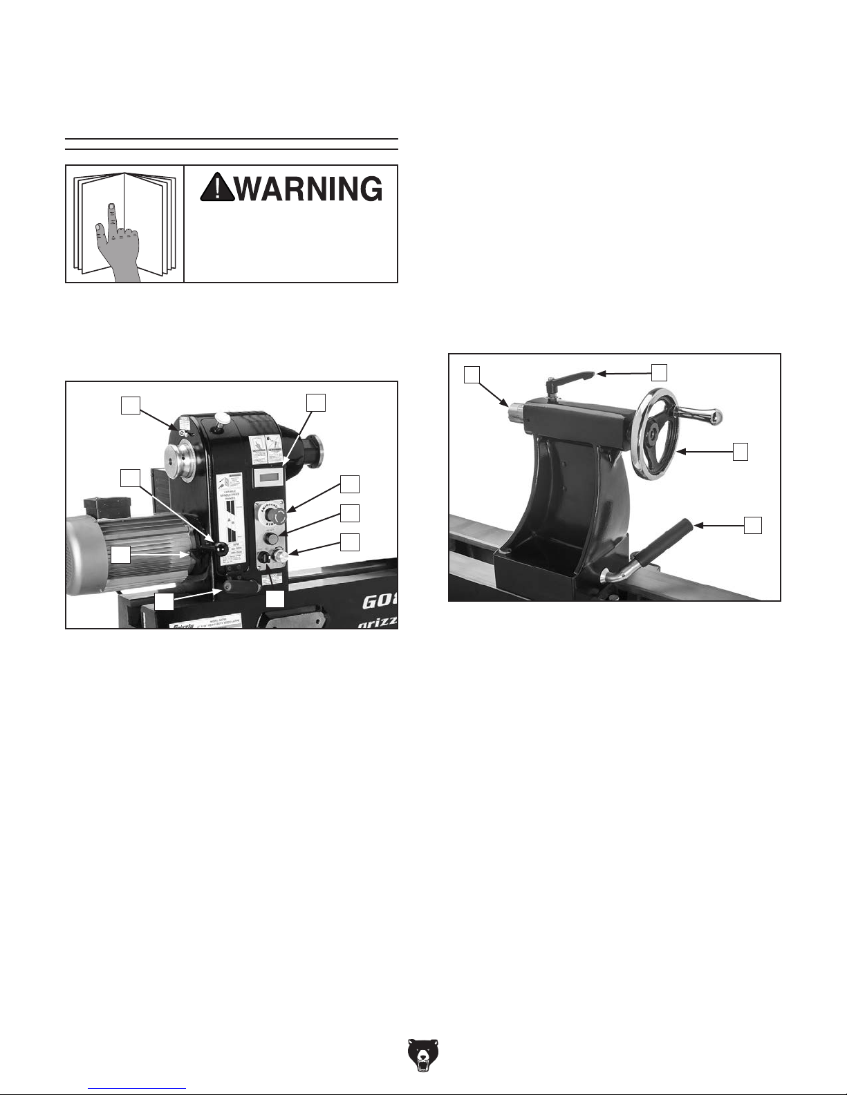
E. Spindle Direction Switch: Toggles spin-
dle direction between forward (FWD) and
reverse (REV).
F. Headstock Lock Lever: Secures headstock
in position along bed.
G. Belt Tension Lock Handle: Locks belt ten-
sion lever in place.
H. Belt Tension Lever: Increases and decreas-
es amount of tension on belt.
Refer to Figures 1–5 and the following descriptions to become familiar with the basic controls of
this machine.
I
H
G
F
Figure 1. Headstock controls.
A. Spindle RPM Readout: Indicates spindle
speed in revolutions per minute (RPM).
A
B
C
D
E
I. Spindle Lock: Locks spindle in place for
indexing operations.
J
Figure 2. Tailstock controls.
J. Quill: Holds centers or tooling. Can be
moved toward and away from spindle.
K. Quill Lock Handle: Secures quill in position.
K
L
M
B. Emergency Stop Button: Stops spindle
rotation. Twist clockwise to reset.
C. Reset Button: Enables spindle rotation after
Emergency Stop button has been disengaged or power has been lost.
D. Speed Control Knob: Adjusts spindle speed
from low to high within range governed by
pulley belt position.
-4-
L. Tailstock Handwheel: Moves quill toward
and away from spindle.
M. Tailstock Lock Lever: Secures tailstock in
position along bed.
Model G0799 G0800 (Mfd. Since 09/15)

N O
S
P
Figure 3. Tool rest controls.
N. Tool Rest: Provides stable platform for cut-
ting tools.
O. Tool Rest Lock Handle: Secures tool rest in
position.
P. Tool Rest Base (Banjo) Lock Lever:
Secures tool rest base (banjo) in position
along bed.
Q
R
Figure 5. Locking pin used to secure chuck
guard.
S. Chuck Guard Locking Pin: Secures chuck
guard in position. Pull pin up to release locking mechanism and allow guard to rotate.
Figure 4. Swing-away bed components.
Q. Swing-Away Bed: Provides extended bed
length for turning operations, and swings
around side of bed to store tailstock during
outboard turning operations.
R. Swing-Away Bed Latch: Locks swing-away
bed securely against lathe bedway.
Model G0799 G0800 (Mfd. Since 09/15)
-5-

Glossary Of Terms
The following is a list of common definitions, terms and phrases used throughout this manual as they relate
to this wood lathe and turning in general. Become familiar with these terms for assembling, adjusting or
operating this machine. Your safety is VERY important to us at Grizzly!
Bed: The long, rail-like metal base to which
the tailstock, tool base, and headstock are
attached.
Chuck: A mechanical device that attaches to the
spindle and holds the workpiece using clamping force from attached jaws.
Faceplate: The metal disc that threads onto the
headstock spindle and is used as an alternate
means of holding a workpiece, such as a bowl,
that can't be mounted between centers.
Faceplate Turning: Turning situation in which
the grain of the turning stock is at right angles
to the lathe bed axis, or for workpieces that
can't be held between centers, such as bowls.
Backing Block: A sacrificial piece of wood glued
to the base of the workpiece and screwed to
the faceplate. Often used to prevent mounting marks from appearing on the completed
workpiece.
Headstock: The cast metal box to which the
motor is attached and contains the spindle,
bearings, belts, and electrical components for
operating the lathe.
Index Head: The mechanism that allows the
headstock spindle to be locked at specific
intervals for layout or other auxiliary tasks.
Offset Turning: A turning situation where the
center of the workpiece is offset at various
stages of the work to produce different shapes.
Outboard Turning: Turning of workpiece with
the headstock situated at the far end of the
lathe so the work done is not over the bed of
the lathe.
Roughing Out: Taking stock from square billet to
round blank.
Spindle: This term has two meanings. First, it
refers to the threaded shaft in the headstock
to which the faceplate is attached. Second, it
refers to any work that is spindle-turned.
Spindle-Turning: Work performed where the
grain and length of the workpiece are parallel to the axis of the bed, or the workpiece is
held between the spindle center and tailstock
center.
Swing: The capacity of the lathe, measured
by doubling the distance from the bed to the
spindle center.
Tailstock: The metal component at the opposite
end of the bed from the headstock containing a
quill and live or dead centers. It maintains pressure on the spindle-turned workpiece.
Tool Rest Base (a.k.a. Banjo): The movable
metal fixture attached to the bed upon which
the tool rest is fixed.
Tool Rest: The adjustable metal arm upon which
the tool rests during a turning operation.
Way: One of the metal rails that make up the bed
of the lathe.
-6-
Model G0799 G0800 (Mfd. Since 09/15)

G0799 Machine Data Sheet
MACHINE DATA
SHEET
Customer Service #: (570) 546-9663 · To Order Call: (800) 523-4777 · Fax #: (800) 438-5901
MODEL G0799 20" X 48" HEAVY‐DUTY WOOD LATHE
Product Dimensions:
Weight.............................................................................................................................................................. 749 lbs.
Width (side-to-side) x Depth (front-to-back) x Height........................................................................... 26 x 89 x 54 in.
Footprint (Length x Width)..................................................................................................................... 55-1/2 x 26 in.
Shipping Dimensions:
Type..................................................................................................................................... Cardboard w/Wood Skids
Content........................................................................................................................................................... Machine
Weight.............................................................................................................................................................. 826 lbs.
Length x Width x Height....................................................................................................................... 58 x 31 x 30 in.
Must Ship Upright................................................................................................................................................... Yes
Electrical:
Power Requirement........................................................................................................... 220V, Single-Phase, 60 Hz
Prewired Voltage.................................................................................................................................................. 220V
Full-Load Current Rating........................................................................................................................................ 10A
Minimum Circuit Size.............................................................................................................................................. 15A
Connection Type....................................................................................................................................... Cord & Plug
Power Cord Included.............................................................................................................................................. Yes
Power Cord Length................................................................................................................................................. 6 ft.
Power Cord Gauge......................................................................................................................................... 14 AWG
Plug Included.......................................................................................................................................................... Yes
Included Plug Type................................................................................................................................................ 6-15
Switch Type.............................................................................................................................................. Push Button
Inverter Type............................................................................................................................... Delta VFD015EL21A
Inverter Size......................................................................................................................................................... 2 HP
Motors:
Main
Type........................................................................................................................................... TEFC Induction
Horsepower................................................................................................................................................ 2 HP
Phase.................................................................................................................................................... 3-Phase
Amps........................................................................................................................................................... 6.5A
Speed................................................................................................................................................ 1720 RPM
Power Transfer .................................................................................................................................. Belt Drive
Bearings..................................................................................................... Shielded & Permanently Lubricated
Main Specifications:
Operation Information
Swing Over Bed......................................................................................................................................... 20 in.
Swing Over Tool Rest Base....................................................................................................................... 16 in.
Distance Between Centers........................................................................................................................ 48 in.
Max. Distance Tool Rest to Spindle Center............................................................................................... 15 in.
No of Spindle Speeds............................................................................................................................ Variable
Spindle Speed Range................................................................................................................ 60 – 3500 RPM
Floor to Center Height............................................................................................................................... 44 in.
Headstock Rotation................................................................................................................................... Fixed
Model G0799 G0800 (Mfd. Since 09/15)
-7-

Spindle Information
Spindle Taper............................................................................................................................................ MT#2
Spindle Thread Size.................................................................................................................. 1-1/4 in. x 8 TPI
Spindle Thread Direction.................................................................................................................. Right-Hand
Spindle Bore......................................................................................................................................... 0.625 in.
Type of Included Spindle Center................................................................................................................. Spur
Indexed Spindle Increments............................................................................................................... 7-1/2 deg.
No of Indexes................................................................................................................................................. 48
Outboard Spindle Thread Direction.................................................................................................. Right-Hand
Outboard Spindle Size........................................................................................................................... 1-1/4 in.
Outboard Spindle TPI................................................................................................................................ 8 TPI
Tool Rest Information
Tool Rest Width................................................................................................................................... 14-1/4 in.
Tool Rest Post Diameter.............................................................................................................................. 1 in.
Tool Rest Post Length......................................................................................................................... 5-5/16 in.
Tool Rest Base Height......................................................................................................................... 2-5/16 in.
Tailstock Information
Tailstock Taper.......................................................................................................................................... MT#2
Type of Included Tailstock Center.................................................................................................... Live Center
Construction
Bed....................................................................................................................................................... Cast Iron
Frame................................................................................................................................................... Cast Iron
Stand.................................................................................................................................................... Cast Iron
Base..................................................................................................................................................... Cast Iron
Headstock............................................................................................................................................ Cast Iron
Tailstock............................................................................................................................................... Cast Iron
Paint Type/Finish.................................................................................................................................... Enamel
Other Related Information
Bed Width............................................................................................................................................ 8-5/16 in.
Faceplate Size....................................................................................................................................... 3-1/4 in.
Other Specifications:
Country of Origin ................................................................................................................................................ China
Warranty ........................................................................................................................................................... 1 Year
Approximate Assembly & Setup Time .............................................................................................................. 1 Hour
Serial Number Location .................................................................................................................................. ID Label
ISO 9001 Factory .................................................................................................................................................. Yes
Certified by a Nationally Recognized Testing Laboratory (NRTL) ......................................................................... Yes
Features:
Electronic Variable-Speed Spindle Control with Digital RPM Readout
Forward/Reverse Switch
15" Maximum Distance from Tool Rest to Spindle Centerline
Low Spindle Speed Range of 60–1000 RPM and a High-Speed Range of 200–3500 RPM
Headstock Can Be Positioned Anywhere Along Bed
12" Swing-Away Bed for Easy Tailstock Storage
7-1/2° Spindle Indexing
4-1/2" Tailstock Quill Travel
Built-In Tool Holder
Headstock, Tailstock, and Tool Rest Support Have Lever-Action Cam-Locks for Quick Positioning
Adjustable Leveling Feet
-8-
Model G0799 G0800 (Mfd. Since 09/15)

G0800 Machine Data Sheet
MACHINE DATA
SHEET
Customer Service #: (570) 546-9663 · To Order Call: (800) 523-4777 · Fax #: (800) 438-5901
MODEL G0800 24" X 48" HEAVY‐DUTY WOOD LATHE
Product Dimensions:
Weight.............................................................................................................................................................. 767 lbs.
Width (side-to-side) x Depth (front-to-back) x Height..................................................................... 26 x 90 x 57-1/2 in.
Footprint (Length x Width)..................................................................................................................... 55-1/2 x 26 in.
Shipping Dimensions:
Type............................................................................................................................ Cardboard Box on Wood Skids
Content........................................................................................................................................................... Machine
Weight.............................................................................................................................................................. 845 lbs.
Length x Width x Height....................................................................................................................... 58 x 31 x 30 in.
Must Ship Upright................................................................................................................................................... Yes
Electrical:
Power Requirement........................................................................................................... 220V, Single-Phase, 60 Hz
Full-Load Current Rating........................................................................................................................................ 15A
Minimum Circuit Size.............................................................................................................................................. 20A
Connection Type....................................................................................................................................... Cord & Plug
Power Cord Included.............................................................................................................................................. Yes
Power Cord Length................................................................................................................................................. 6 ft.
Power Cord Gauge......................................................................................................................................... 14 AWG
Plug Included.......................................................................................................................................................... Yes
Included Plug Type................................................................................................................................................ 6-15
Switch Type.............................................................................................................................................. Push Button
Inverter Type................................................................................................................................. Delta VFD022E21A
Inverter Size......................................................................................................................................................... 3 HP
Motors:
Main
Type........................................................................................................................................... TEFC Induction
Horsepower................................................................................................................................................ 3 HP
Phase.................................................................................................................................................... 3-Phase
Amps............................................................................................................................................................ 10A
Speed................................................................................................................................................ 1720 RPM
Power Transfer .................................................................................................................................. Belt Drive
Bearings..................................................................................................... Shielded & Permanently Lubricated
Main Specifications:
Operation Information
Swing Over Bed......................................................................................................................................... 24 in.
Swing Over Tool Rest Base....................................................................................................................... 20 in.
Distance Between Centers........................................................................................................................ 48 in.
Max. Distance Tool Rest to Spindle Center............................................................................................... 15 in.
No of Spindle Speeds............................................................................................................................ Variable
Spindle Speed Range................................................................................................................ 60 – 3500 RPM
Floor to Center Height............................................................................................................................... 46 in.
Headstock Rotation................................................................................................................................... Fixed
Model G0799 G0800 (Mfd. Since 09/15)
-9-

Spindle Information
Spindle Taper............................................................................................................................................ MT#2
Spindle Thread Size.................................................................................................................. 1-1/4 in. x 8 TPI
Spindle Thread Direction.................................................................................................................. Right-Hand
Spindle Bore......................................................................................................................................... 0.625 in.
Type of Included Spindle Center................................................................................................................. Spur
Indexed Spindle Increments............................................................................................................... 7-1/2 deg.
No of Indexes................................................................................................................................................. 48
Outboard Spindle Thread Direction............................................................................................................ Right
Outboard Spindle Size........................................................................................................................... 1-1/4 in.
Outboard Spindle TPI................................................................................................................................ 8 TPI
Tool Rest Information
Tool Rest Width................................................................................................................................... 14-1/4 in.
Tool Rest Post Diameter.............................................................................................................................. 1 in.
Tool Rest Post Length......................................................................................................................... 5-5/16 in.
Tool Rest Base Height......................................................................................................................... 2-5/16 in.
Tailstock Information
Tailstock Taper.......................................................................................................................................... MT#2
Type of Included Tailstock Center............................................................................................................... Live
Construction
Bed....................................................................................................................................................... Cast Iron
Frame................................................................................................................................................... Cast Iron
Stand.................................................................................................................................................... Cast Iron
Base..................................................................................................................................................... Cast Iron
Headstock............................................................................................................................................ Cast Iron
Tailstock............................................................................................................................................... Cast Iron
Paint Type/Finish.................................................................................................................................... Enamel
Other Related Information
Bed Width............................................................................................................................................ 8-5/16 in.
Faceplate Size....................................................................................................................................... 3-1/4 in.
Other Specifications:
Country of Origin ................................................................................................................................................ China
Warranty ........................................................................................................................................................... 1 Year
Approximate Assembly & Setup Time .............................................................................................................. 1 Hour
Serial Number Location .................................................................................................................................. ID Label
ISO 9001 Factory .................................................................................................................................................. Yes
Certified by a Nationally Recognized Testing Laboratory (NRTL) ......................................................................... Yes
Features:
Electronic Variable-Speed Spindle Control with Digital RPM Readout
Forward/Reverse Switch
15" Maximum Distance from Tool Rest to Spindle Centerline
12" Swing-Away Bed for Easy Tailstock Storage
Low Spindle Speed Range of 60 to 1000 RPM and a High-Speed Range of 200-3500 RPM
Headstock Can Be Positioned Anywhere Along the Bed
7-1/2º Spindle Indexing
Tailstock, Headstock, and Tool Rest Support Have Lever-Action Cam-Locks for Quick Positioning
Adjustable Leveling Feet
4-1/2" Tailstock Quill Travel
Built-In Tool Holder
-10 -
Model G0799 G0800 (Mfd. Since 09/15)

SECTION 1: SAFETY
For Your Own Safety, Read Instruction
Manual Before Operating This Machine
The purpose of safety symbols is to attract your attention to possible hazardous conditions.
This manual uses a series of symbols and signal words intended to convey the level of importance of the safety messages. The progression of symbols is described below. Remember that
safety messages by themselves do not eliminate danger and are not a substitute for proper
accident prevention measures. Always use common sense and good judgment.
Indicates an imminently hazardous situation which, if not avoided,
WILL result in death or serious injury.
Indicates a potentially hazardous situation which, if not avoided,
COULD result in death or serious injury.
Indicates a potentially hazardous situation which, if not avoided,
MAY result in minor or moderate injury. It may also be used to alert
against unsafe practices.
This symbol is used to alert the user to useful information about
NOTICE
proper operation of the machine.
Safety Instructions for Machinery
OWNER’S MANUAL. Read and understand this
owner’s manual BEFORE using machine.
TRAINED OPERATORS ONLY. Untrained operators have a higher risk of being hurt or killed.
Only allow trained/supervised people to use this
machine. When machine is not being used, disconnect power, remove switch keys, or lock-out
machine to prevent unauthorized use—especially
around children. Make workshop kid proof!
DANGEROUS ENVIRONMENTS. Do not use
machinery in areas that are wet, cluttered, or have
poor lighting. Operating machinery in these areas
greatly increases the risk of accidents and injury.
MENTAL ALERTNESS REQUIRED. Full mental
alertness is required for safe operation of machinery. Never operate under the influence of drugs or
alcohol, when tired, or when distracted.
ELECTRICAL EQUIPMENT INJURY RISKS. You
can be shocked, burned, or killed by touching live
electrical components or improperly grounded
machinery. To reduce this risk, only allow qualified
service personnel to do electrical installation or
repair work, and always disconnect power before
accessing or exposing electrical equipment.
DISCONNECT POWER FIRST.
nect machine from power supply BEFORE making
adjustments, changing tooling, or servicing machine.
This prevents an injury risk from unintended startup
or contact with live electrical components.
EYE PROTECTION. Always wear ANSI-approved
safety glasses or a face shield when operating or
observing machinery to reduce the risk of eye
injury or blindness from flying particles. Everyday
eyeglasses are NOT approved safety glasses.
Always discon-
Model G0799 G0800 (Mfd. Since 09/15)
-11-

WEARING PROPER APPAREL. Do not wear
clothing, apparel or jewelry that can become
entangled in moving parts. Always tie back or
cover long hair. Wear non-slip footwear to reduce
risk of slipping and losing control or accidentally
contacting cutting tool or moving parts.
HAZARDOUS DUST. Dust created by machinery
operations may cause cancer, birth defects, or
long-term respiratory damage. Be aware of dust
hazards associated with each workpiece material. Always wear a NIOSH-approved respirator to
reduce your risk.
HEARING PROTECTION. Always wear hearing protection when operating or observing loud
machinery. Extended exposure to this noise
without hearing protection can cause permanent
hearing loss.
REMOVE ADJUSTING TOOLS. Tools left on
machinery can become dangerous projectiles
upon startup. Never leave chuck keys, wrenches,
or any other tools on machine. Always verify
removal before starting!
USE CORRECT TOOL FOR THE JOB. Only use
this tool for its intended purpose—do not force
it or an attachment to do a job for which it was
not designed. Never make unapproved modifications—modifying tool or using it differently than
intended may result in malfunction or mechanical
failure that can lead to personal injury or death!
AWKWARD POSITIONS. Keep proper footing
and balance at all times when operating machine.
Do not overreach! Avoid awkward hand positions
that make workpiece control difficult or increase
the risk of accidental injury.
CHILDREN & BYSTANDERS. Keep children and
bystanders at a safe distance from the work area.
Stop using machine if they become a distraction.
GUARDS & COVERS. Guards and covers reduce
accidental contact with moving parts or flying
debris. Make sure they are properly installed,
undamaged, and working correctly BEFORE
operating machine.
FORCING MACHINERY. Do not force machine.
It will do the job safer and better at the rate for
which it was designed.
NEVER STAND ON MACHINE. Serious injury
may occur if machine is tipped or if the cutting
tool is unintentionally contacted.
STABLE MACHINE. Unexpected movement during operation greatly increases risk of injury or
loss of control. Before starting, verify machine is
stable and mobile base (if used) is locked.
USE RECOMMENDED ACCESSORIES. Consult
this owner’s manual or the manufacturer for recommended accessories. Using improper accessories will increase the risk of serious injury.
UNATTENDED OPERATION. To reduce the
risk of accidental injury, turn machine OFF and
ensure all moving parts completely stop before
walking away. Never leave machine running
while unattended.
MAINTAIN WITH CARE. Follow all maintenance
instructions and lubrication schedules to keep
machine in good working condition. A machine
that is improperly maintained could malfunction,
leading to serious personal injury or death.
DAMAGED PARTS. Regularly inspect machine
for damaged, loose, or mis-adjusted parts—or
any condition that could affect safe operation.
Immediately repair/replace BEFORE operating
machine. For your own safety, DO NOT operate
machine with damaged parts!
MAINTAIN POWER CORDS. When disconnecting cord-connected machines from power, grab
and pull the plug—NOT the cord. Pulling the cord
may damage the wires inside. Do not handle
cord/plug with wet hands. Avoid cord damage by
keeping it away from heated surfaces, high traffic
areas, harsh chemicals, and wet/damp locations.
EXPERIENCING DIFFICULTIES. If at any time
you experience difficulties performing the intended operation, stop using the machine! Contact our
Technical Support at (570) 546-9663.
-12-
Model G0799 G0800 (Mfd. Since 09/15)

Additional Safety for Wood Lathes
Serious injury or death can occur from getting entangled in, crushed between, or struck
by rotating parts on a lathe! Rotating workpieces can come loose and strike operator or
bystanders with deadly force if they are improperly secured, rotated too fast, or are not strong
enough for the rotational forces required for turning. Improper tool setup or usage can cause
tool kickback or grabbing, resulting in impact injury or entanglement. To reduce the risk of
operator (or bystander) injury or death, anyone operating this machine MUST completely heed
the hazards and warnings below.
CHECK WORKPIECE INTEGRITY. Verify each
workpiece is free of knots, splits, nails, or foreign
material to ensure it can safely rotate on spindle
without breaking apart or causing tool kickback.
PROPERLY PREPARE WORKPIECE.
Before mounting, cut off waste portions to
balance workpiece for safe rotation and remove
large edges that can catch on tooling.
SECURE LOCKS. Verify tool rest, headstock,
and tailstock are secure before turning lathe ON.
SECURE WORKPIECE. Use proven setup
techniques and always verify workpiece is
well-secured before starting lathe. Only use
high-quality fasteners with non-tapered heads for
faceplate attachment.
ADJUST TOOL SUPPORT. An improperly supported tool may be grabbed or ejected. Adjust tool
rest approximately
1
⁄8" above workpiece center line to provide proper
support for turning tool. Firmly hold turning tool
with both hands against tool rest.
1
⁄4" away from workpiece and
WEAR PROPER PPE. Always wear a face shield
and safety glasses when operating lathe. Do not
wear gloves, necktie or loose clothing. Keep long
hair away from rotating spindle.
USE CORRECT SPEEDS. Select correct spindle
speed for workpiece size, type, shape, and
condition. Use low speeds when roughing or when
turning large, long, or non-concentric workpieces.
Allow spindle to reach full speed before turning.
AVOID TOOL KICKBACK. This occurs when
turning tool is grabbed or ejected from workpiece
with great force. Commonly caused by poor
workpiece selection/preparation, improper tool
usage, or improper machine setup or tool rest
adjustment.
SAFELY PERFORM ROUGHING. Use correct
tool. Take light cuts, use low speeds, and firmly
support tool with both hands.
USE SHARP TOOLS. Sharp tools cut with
less resistance than dull tools. Using dull tools
increases the risk of tool kickback or grabbing.
TEST NEW SETUPS. Test each new setup by
starting spindle rotation at lowest speed and
standing to side of lathe until workpiece reaches
full speed and you can verify safe rotation.
REMOVE ADJUSTMENT TOOLS. Remove all
chuck keys, wrenches, and adjustment tools
before turning lathe ON. These items can become
deadly projectiles when spindle is started.
CHECK CLEARANCES. Before starting spindle,
verify workpiece has adequate clearance by
hand-rotating it through its entire range of motion.
Model G0799 G0800 (Mfd. Since 09/15)
SAFELY STOPPING ROTATION. Always allow
rotating workpiece to stop on its own. Never put
hands or another object on workpiece to stop it.
SAFELY MEASURE WORKPIECE. Only measure
workpiece after it has stopped. Trying to measure
a spinning workpiece increases entanglement
risk.
SANDING/POLISHING. To reduce entanglement
risk, remove tool rest before sanding. Never
completely wrap sandpaper around workpiece.
-13-

SECTION 2: POWER SUPPLY
Before installing the machine, consider the availability and proximity of the required power supply
circuit. If an existing circuit does not meet the
requirements for this machine, a new circuit must
be installed. To minimize the risk of electrocution,
fire, or equipment damage, installation work and
electrical wiring must be done by an electrician or
qualified service personnel in accordance with all
applicable codes and standards.
or equipment damage
may occur if machine is
not properly grounded
and connected to power
The full-load current rating is the amperage a
machine draws at 100% of the rated output power.
On machines with multiple motors, this is the
amperage drawn by the largest motor or sum of all
motors and electrical devices that might operate
at one time during normal operations.
The full-load current is not the maximum amount
of amps that the machine will draw. If the machine
is overloaded, it will draw additional amps beyond
the full-load rating.
If the machine is overloaded for a sufficient length
of time, damage, overheating, or fire may result—
especially if connected to an undersized circuit.
To reduce the risk of these hazards, avoid overloading the machine during operation and make
sure it is connected to a power supply circuit that
meets the specified circuit requirements.
For your own safety and protection of
Note: Circuit requirements in this manual apply to
a dedicated circuit—where only one machine will
be running on the circuit at a time. If machine will
be connected to a shared circuit where multiple
machines may be running at the same time, consult an electrician or qualified service personnel to
ensure circuit is properly sized for safe operation.
A power supply circuit includes all electrical
equipment between the breaker box or fuse panel
in the building and the machine. The power supply circuit used for this machine must be sized to
safely handle the full-load current drawn from the
machine for an extended period of time. (If this
machine is connected to a circuit protected by
fuses, use a time delay fuse marked D.)
This machine is prewired to operate on a power
supply circuit that has a verified ground and meets
the following requirements:
Availability
Electrocution, fire, shock,
supply.
Full-Load Current Rating
Circuit Information
property, consult an electrician if you are
unsure about wiring practices or electrical
codes in your area.
G0799 Full-Load Current Rating ...... 6.5 Amps
G0800 Full-Load Current Rating ....... 10 Amps
-14-
Circuit Requirements
Nominal Voltage .........208V, 22 0V, 230V, 240V
Cycle ..........................................................60 Hz
Phase ........................................... Single-Phase
G0799 Power Supply Circuit ............. 15 Amps
G0800 Power Supply Circuit ............. 15 Amps
Plug/Receptacle ............................. NEMA 6-15
Model G0799 G0800 (Mfd. Since 09/15)
Improper connection of the equipment-grounding
wire can result in a risk of electric shock. The
wire with green insulation (with or without yellow
stripes) is the equipment-grounding wire. If repair
or replacement of the power cord or plug is necessary, do not connect the equipment-grounding
wire to a live (current carrying) terminal.
Check with a qualified electrician or service personnel if you do not understand these grounding
requirements, or if you are in doubt about whether
the tool is properly grounded. If you ever notice
that a cord or plug is damaged or worn, disconnect it from power, and immediately replace it with
a new one.
We do not recommend using an extension cord
with this machine.
cord, only use it if absolutely necessary and only
on a temporary basis.
Extension cords cause voltage drop, which can
damage electrical components and shorten motor
life. Voltage drop increases as the extension cord
size gets longer and the gauge size gets smaller
(higher gauge numbers indicate smaller sizes).
Any extension cord used with this machine must
be in good condition and contain a ground wire
and matching plug/receptacle. Additionally, it must
meet the following size requirements:
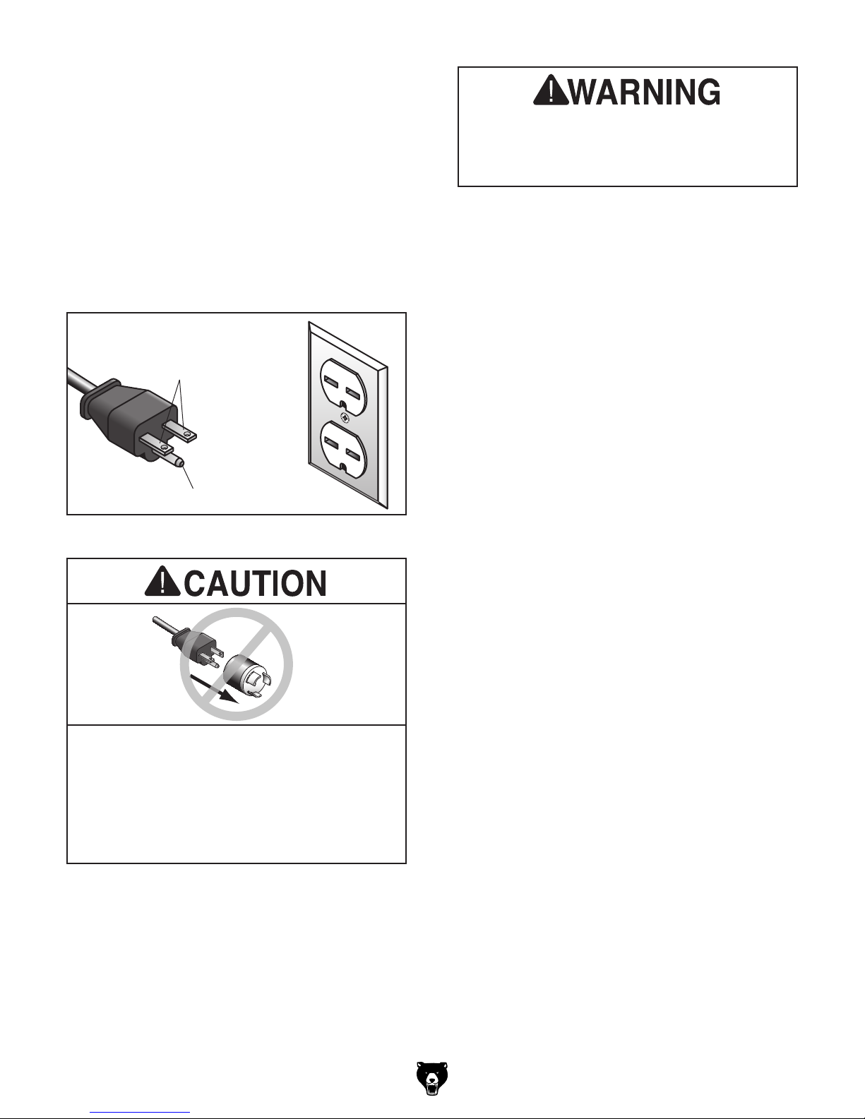
Grounding Requirements
This machine MUST be grounded. In the event
of certain malfunctions or breakdowns, grounding
reduces the risk of electric shock by providing a
path of least resistance for electric current.
This machine is equipped with a power cord that
has an equipment-grounding wire and a grounding
plug. Only insert plug into a matching receptacle
(outlet) that is properly installed and grounded in
accordance with all local codes and ordinances.
DO NOT modify the provided plug!
No adapter should be used with plug. If
plug does not fit available receptacle, or if
GROUNDED
6-15 RECEPTACLE
Current Carrying Prongs
6-15 PLUG
Serious injury could occur if you connect
machine to power before completing setup
process. DO NOT connect to power until
instructed later in this manual.
Grounding Prong
Figure 6. Typical 6-15 plug and receptacle.
machine must be reconnected for use on a
different type of circuit, reconnection must
be performed by an electrician or qualified
service personnel, and it must comply with
all local codes and ordinances.
Model G0799 G0800 (Mfd. Since 09/15)
Extension Cords
If you must use an extension
G0799 Minimum Gauge Size ............... 14 AWG
G0800 Minimum Gauge Size ...............12 AWG
Maximum Length (Shorter is Better).......50 ft.
-15-
SECTION 3: SETUP
This machine was carefully packaged for safe
transport. When unpacking, separate all enclosed
items from packaging materials and inspect them
for shipping damage.
,
please
IMPORTANT:
you are completely satisfied with the machine and
have resolved any issues between Grizzly or the
shipping agent. You MUST have the original pack-
aging to file a freight claim. It is also extremely
helpful if you need to return your machine later.
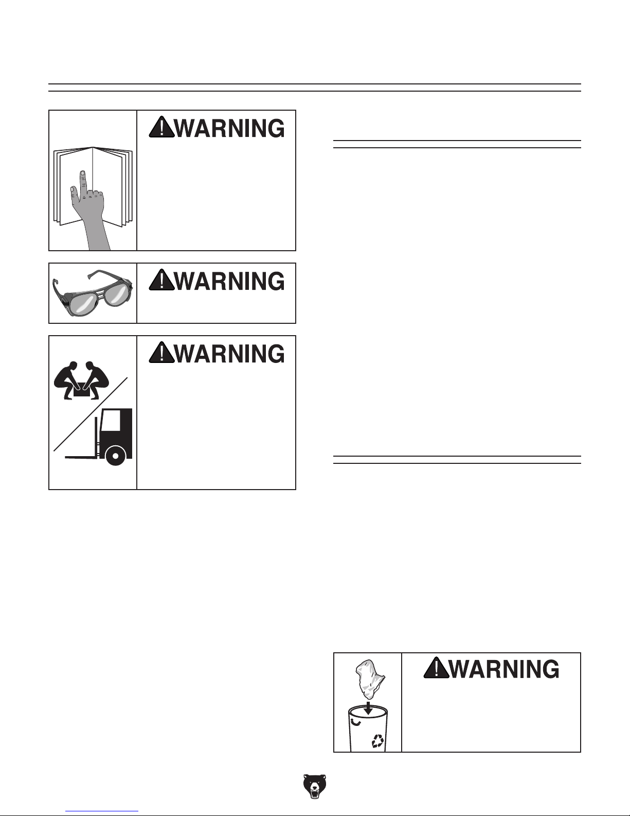
Keep children and pets away
from plastic bags or packing
materials shipped with this
get help from other people
Needed for Setup
This machine presents
serious injury hazards
to untrained users. Read
through this entire manual to become familiar with
the controls and operations before starting the
machine!
The following are needed to complete the setup
process, but are not included with your machine.
• For Lifting and Moving:
— A forklift or other power lifting device rated
for at least 1000 lbs.
— Two lifting straps rated for at least 1000
lbs. each
— Two other people to guide machine
Wear safety glasses during
the entire setup process!
HEAV Y LIFT!
Straining or crushing injury
may occur from improperly
lifting machine or some of
its parts. To reduce this risk,
and use a forklift (or other
lifting equipment) rated for
weight of this machine.
• For Assembly:
— Shop rags
— Cleaner/degreaser (see Page 20)
— Quality metal protectant lubricant
— Safety glasses for each person
— Anchoring hardware as needed (see
Page 27)
— Precision level at least 12" long
Unpacking
If items are damaged
call us immediately at (570) 546-9663.
Save all packaging materials until
-16 -
SUFFOCATION HAZARD!
machine. Discard immediately.
Model G0799 G0800 (Mfd. Since 09/15)
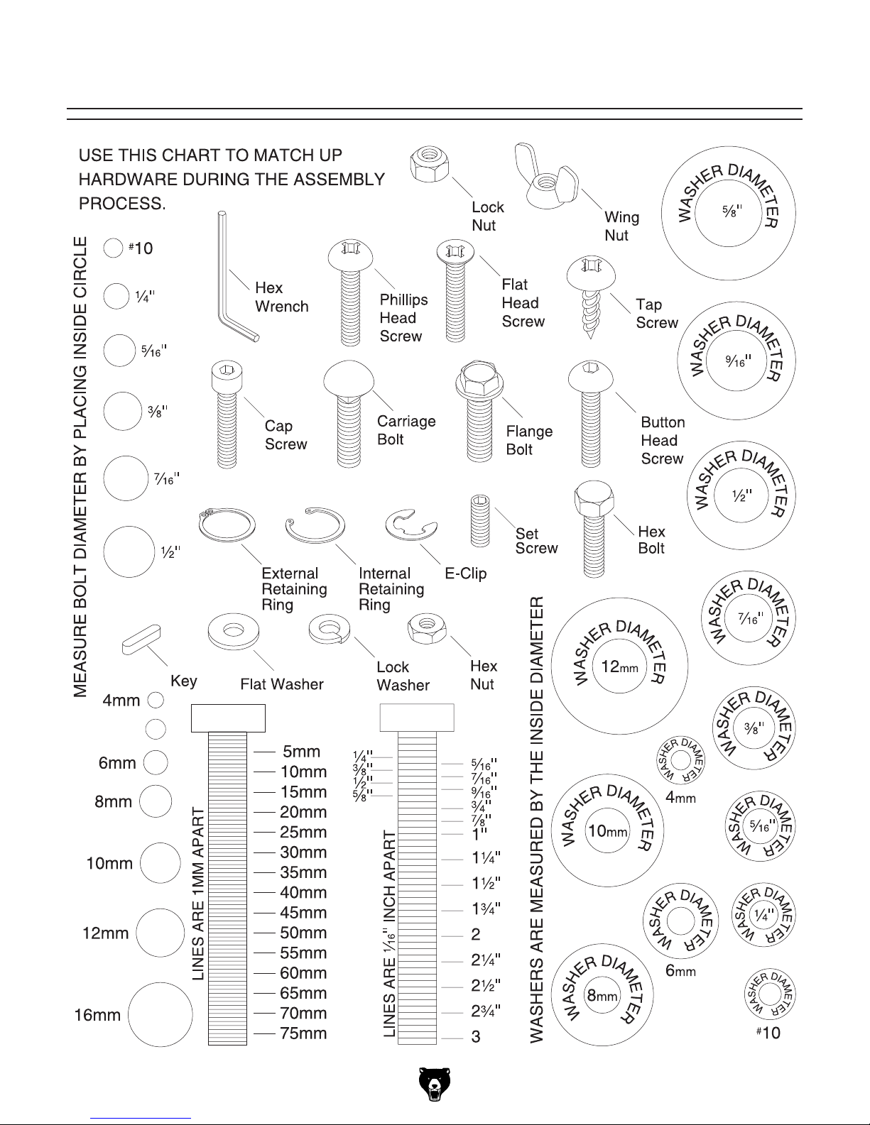
Hardware Recognition Chart
5mm
Model G0799 G0800 (Mfd. Since 09/15)
-17-
Inventory
The following is a list of items shipped with your
machine. Before beginning setup, lay these items
out and inventory them.
If any non-proprietary parts are missing (e.g. a
nut or a washer), we will gladly replace them; or
for the sake of expediency, replacements can be
obtained at your local hardware store.
After all the parts have been removed from the
shipping containers, you should have the following items:
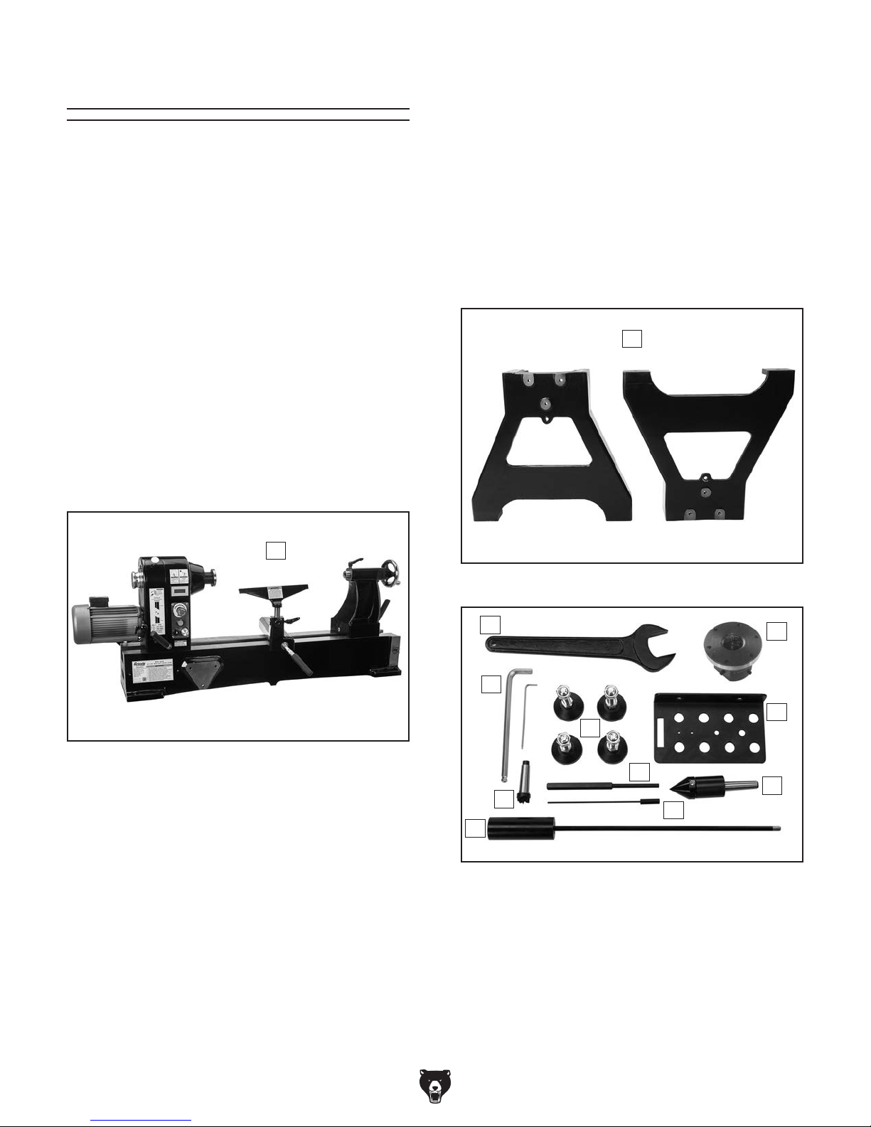
Inventory (Figures 7–10): Qty
A. Lathe Assembly
—Headstock (mounted) ............................. 1
—Tool Rest (mounted) ................................ 1
—Tool Rest Base (mounted) ...................... 1
—Tailstock (mounted) ................................. 1
B. Stand Legs ................................................. 2
C. Open-End Wrench 50mm .......................... 1
D. Faceplate 3" ............................................... 1
—Set Screws M6-1 x 10 ............................. 2
E. Tool Rack .................................................. 1
F. Live Center ................................................ 1
G. Knockout Rod ............................................ 1
H. Hex Wrenches 3, 10mm ........................1 Ea
I. Machine Feet w/Hex Nuts ......................... 4
J. Locating Rod .............................................. 1
K. Live Center Pin ........................................... 1
L. Spur Center ............................................... 1
B
A
Figure 7. Lathe assembly.
Figure 8. Stand legs.
C
H
I
J
L
G
Figure 9. Loose inventory components.
K
D
E
F
-18-
Model G0799 G0800 (Mfd. Since 09/15)
 Loading...