

Page 1
MODEL G0796/G0797
VERTICAL MILL w/POWER
FEED & DRO
OWNER'S MANUAL
(For models manufactured since 1/18)
G0796
COPYRIGHT © AUGUST, 2015 BY GRIZZLY INDUSTRIAL, INC. REVISED MAY, 2018 (MN)
WARNING: NO PORTION OF THIS MANUAL MAY BE REPRODUCED IN ANY SHAPE
OR FORM WITHOUT THE WRITTEN APPROVAL OF GRIZZLY INDUSTRIAL, INC.
#WK17430 PRINTED IN CHINA
G0797
V2 . 0 5.18
Page 2

This manual provides critical safety instructions on the proper setup,
operation, maintenance, and service of this machine/tool. Save this
document, refer to it often, and use it to instruct other operators.
Failure to read, understand and follow the instructions in this manual
may result in fire or serious personal injury—including amputation,
electrocution, or death.
The owner of this machine/tool is solely responsible for its safe use.
This responsibility includes but is not limited to proper installation in
a safe environment, personnel training and usage authorization,
proper inspection and maintenance, manual availability and comprehension, application of safety devices, cutting/sanding/grinding tool
integrity, and the usage of personal protective equipment.
The manufacturer will not be held liable for injury or property damage
from negligence, improper training, machine modifications or misuse.
Some dust created by power sanding, sawing, grinding, drilling, and
other construction activities contains chemicals known to the State
of California to cause cancer, birth defects or other reproductive
harm. Some examples of these chemicals are:
• Lead from lead-based paints.
• Crystalline silica from bricks, cement and other masonry products.
• Arsenic and chromium from chemically-treated lumber.
Your risk from these exposures varies, depending on how often you
do this type of work. To reduce your exposure to these chemicals:
Work in a well ventilated area, and work with approved safety equipment, such as those dust masks that are specially designed to filter
out microscopic particles.
Page 3

Table of Contents
INTRODUCTION ............................................... 2
Contact Info.................................................... 2
Manual Accuracy ........................................... 2
Front View Identification ................................ 3
Model G0796 Headstock Identification .......... 4
Model G0797 Headstock Identification .......... 5
Controls & Components ................................. 6
G0796 Machine Data Sheet .......................... 9
G0797 Machine Data Sheet ........................ 11
SECTION 1: SAFETY ..................................... 13
Safety Instructions for Machinery ................ 13
Additional Safety for Milling Machines ......... 15
SECTION 2: POWER SUPPLY ...................... 16
SECTION 3: SETUP ....................................... 18
Needed for Setup ......................................... 18
Unpacking .................................................... 18
Inventory ...................................................... 19
Cleanup ........................................................ 20
Site Considerations ...................................... 21
Lifting & Placing ........................................... 22
Leveling ........................................................ 23
Anchoring to Floor ....................................... 23
Assembly ..................................................... 24
Power Connection........................................ 25
Test Run ...................................................... 26
Spindle Break-In .......................................... 28
Inspections & Adjustments .......................... 28
SECTION 4: OPERATIONS ........................... 29
Operation Overview ..................................... 29
Positioning Table ......................................... 30
Positioning Headstock ................................. 32
Positioning Ram ........................................... 33
Spindle Speed.............................................. 34
Spindle Downfeed ........................................ 37
Spindle Brake............................................... 41
Loading/Unloading Tooling .......................... 41
SECTION 5: ACCESSORIES ......................... 43
SECTION 6: MAINTENANCE ......................... 46
Schedule ...................................................... 46
Cleaning & Protecting .................................. 46
Lubrication ................................................... 47
Machine Storage .......................................... 50
SECTION 7: SERVICE ................................... 51
Troubleshooting ........................................... 51
Adjusting Gibs .............................................. 54
Adjusting Leadscrew Backlash .................... 55
Tramming Spindle ........................................ 57
Replacing Belts & Brake Shoes ................... 59
SECTION 8: WIRING ...................................... 64
Wiring Safety Instructions ............................ 64
G0796 Motor & Switch Wiring ..................... 65
G0797 Motor & Switch Wiring ..................... 66
SECTION 9: PARTS ....................................... 67
G0796 Main Body ........................................ 67
G0796 Table Leadscrews ............................ 69
G0796 Headstock ....................................... 70
G0796 Downfeed ......................................... 72
G0796 One Shot Oiler ................................. 75
G0796 Accessories ...................................... 76
G0796 Labels............................................... 77
G0797 Main Body ........................................ 78
G0797 Table Leadscrews ............................ 80
G0797 Headstock ........................................ 81
G0797 Headstock Gearing .......................... 83
G0797 Downfeed ......................................... 85
G0797 One Shot Oiler ................................. 88
G0797 Accessories ...................................... 89
G0797 Labels............................................... 90
WARRANTY & RETURNS ............................. 93
Model G0796/G0797 (Mfd. Since 1/18)
-1-
Page 4
INTRODUCTION
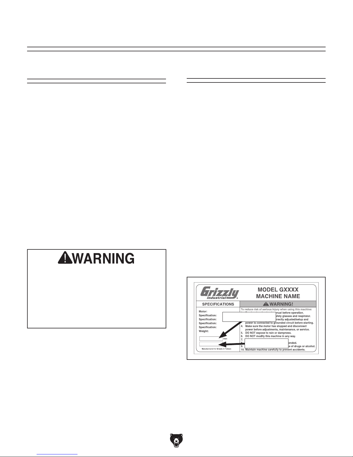
We stand behind our machines! If you have questions or need help, contact us with the information
below. Before contacting, make sure you get the
serial number
from the
machine ID label. This will help us help you faster.
We want your feedback on this manual. What did
you like about it? Where could it be improved?
Please take a few minutes to give us feedback.
Email: manuals@grizzly.com
We are proud to provide a high-quality owner’s
manual with your new machine!
We
instructions, specifications, drawings, and photographs
in this manual. Sometimes we make mistakes, but
our policy of continuous improvement also means
that
you receive is
slightly different than shown in the manual
If you find this to be the case, and the difference
between the manual and machine leaves you
confused or unsure about something
check our
website for an updated version. W
current
manuals and
on our web-
site at
Alternatively, you can call our Technical Support
for help. Before calling, make sure you write down
the
from
the machine ID label (see below). This information
is required for us to provide proper tech support,
and it helps us determine if updated documentation is available for your machine.
Contact Info
and manufacture date
Grizzly Technical Support
1815 W. Battlefield
Springfield, MO 65807
Phone: (570) 546-9663
Email: techsupport@grizzly.com
Grizzly Documentation Manager
P.O. Box 2069
Bellingham, WA 98227-2069
Manual Accuracy
made every effort to be exact with the
sometimes the machine
.
,
e post
manual updates for free
www.grizzly.com.
Manufacture Date and Serial Number
Like all machinery there is potential danger
when operating this machine. Accidents are
frequently caused by lack of familiarity or
failure to pay attention. Use this machine
with respect and caution to decrease the
risk of operator injury. If normal safety precautions are overlooked or ignored, serious
personal injury may occur.
Manufacture Date
Serial Number
-2-
Model G0796/G0797 (Mfd. Since 1/18)
Page 5
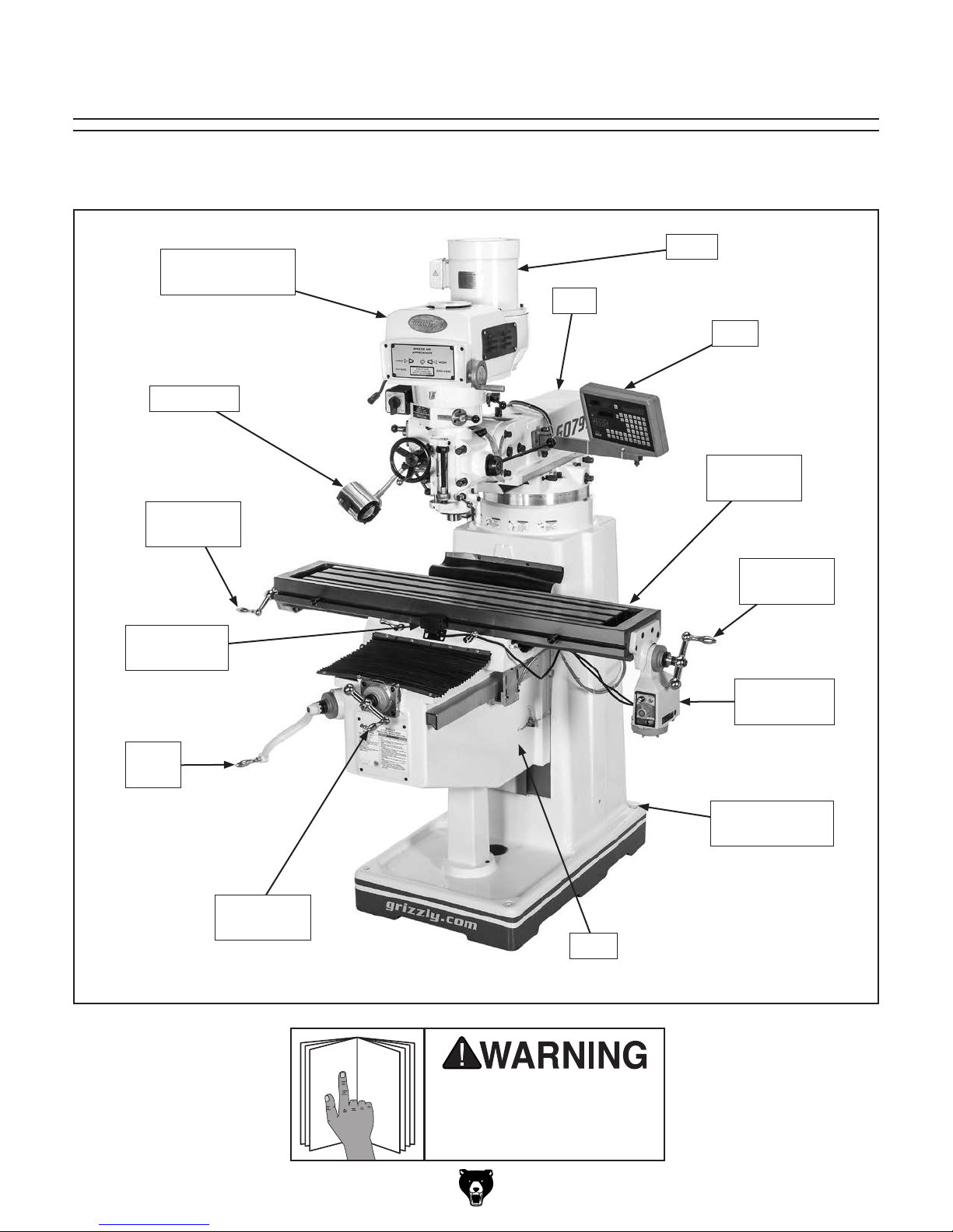
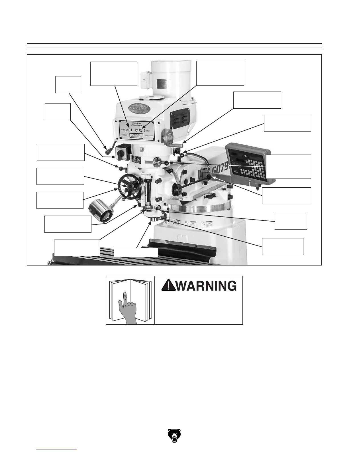
Front View Identification
To reduce your risk of
serious injury, read this
entire manual BEFORE
Become familiar with the names and locations of the controls and features shown below to better understand
the instructions in this manual.
Headstock
(see Pages 4–5)
Work Light
X-Axis
Ball Handle
Power Feed
Limit Switch
Motor
Ram
DRO
Slotted
Work Table
X-Axis
Ball Handle
X-Axis
Power Feed
Knee
Crank
Y-Axis
Ball Handle
Model G0796/G0797 (Mfd. Since 1/18)
Mounting Point
(1 of 4)
Knee
G0797 Shown
using machine.
-3-
Page 6
To reduce your risk of
serious injury, read this
entire manual BEFORE
Model G0796 Headstock Identification
Spindle
Brake
Spindle
Switch
Auto-Downfeed
Rate Selector
Fine Downfeed
Handwheel
Auto-Downfeed
Direction Pin
Fine Downfeed
Clutch Lever
Adjustable
Downfeed Stop
High/Low
Range Lever
Quill & Spindle
Belt Tension
Adjustment Lever
Motor Lock
Lever
Belt Housing
Safety Cover
Spindle Speed
Range Selector
Manual/Power
Downfeed
Selector
Coarse
Downfeed Lever
Quill Lock
Lever
Dial Indicator
Rod
-4-
using machine.
Model G0796/G0797 (Mfd. Since 1/18)
Page 7
To reduce your risk of
serious injury, read this
entire manual BEFORE
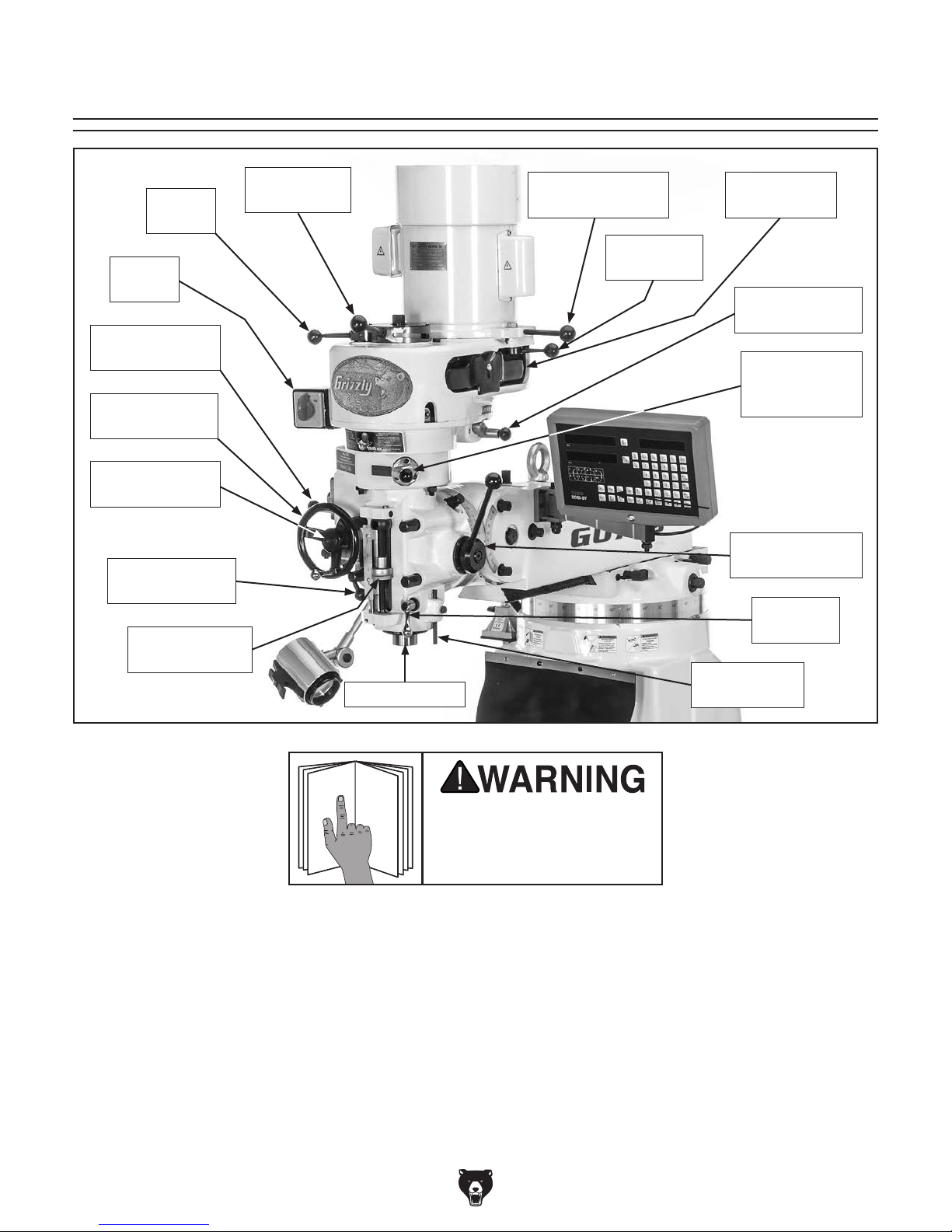
Model G0797 Headstock Identification
Spindle
Brake
Spindle
Switch
Auto-Downfeed
Rate Selector
Auto-Downfeed
Direction Pin
Fine Downfeed
Handwheel
Fine Downfeed
Clutch Lever
Low-Range
Variable-Speed
Indicator
High-Range
Variable-Speed
Indicator
Variable-Speed
Handwheel
Spindle Speed
Range Selector
Manual/Power
Downfeed
Selector
Coarse
Downfeed Lever
Quill Lock
Lever
Adjustable
Downfeed Stop
Quill & Spindle
Dial Indicator
Rod
using machine.
Model G0796/G0797 (Mfd. Since 1/18)
-5-
Page 8
Controls &
To reduce your risk of
serious injury, read this
entire manual BEFORE
Components
F. Spindle Speed Range Selector: Used
in conjunction with high/low range lever.
Engages back gear for low (80–325 RPM),
and disengages back gear for high (660–
2720 RPM) spindle speed ranges.
Note: When engaged, back gear reverses
spindle rotation, causing spindle switch settings to be reversed in low range (see Spindle
Switch on Page 7 for more information).
using machine.
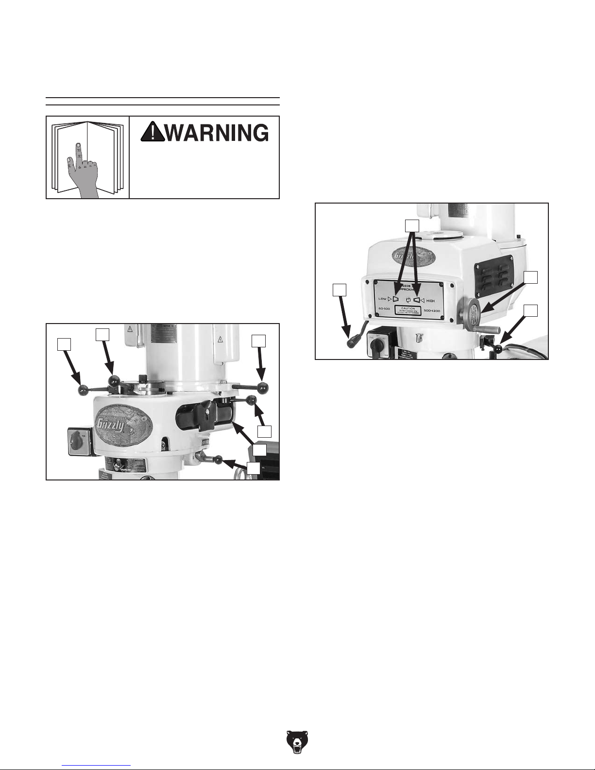
Refer to Figures 1–5 and the following descriptions to become familiar with the basic controls
and components of this machine. Understanding
these items and how they work will help you
understand the rest of the manual and stay safe
when operating this machine.
Upper Headstock (G0796)
B
A
Figure 1. Model G0796 upper headstock
controls and components.
C
D
E
F
Upper Headstock (G0797)
H
I
G
J
Figure 2. Model G0797 upper headstock
controls and components.
G. Spindle Brake Lever: Quickly stops spindle
AFTER power to spindle is turned OFF.
H. Variable-Speed Indicators: Indicate spindle
speed in high and low range.
I. Variable-Speed Handwheel: Selects desired
spindle speed within high or low range.
A. Spindle Brake Lever: Quickly stops spindle
AFTER power to spindle is turned OFF.
B. High/Low Range Lever: Selects between
low (80 RPM–325 RPM) and high (660 RPM–
2720 RPM) spindle speed ranges.
C. Belt Tension Adjustment Lever: Adjusts
V-belt tension by moving position of motor.
D. Motor Lock Lever: Locks motor position to
secure belt tension.
E. Belt Safety Cover: Protects user from entan-
glement during operation. Remove to access
V-belt when changing spindle speed.
-6-
J. Spindle Speed Range Selector: Engages
back gear for low (60 RPM–500 RPM), and
disengages back gear for high (500 RPM–
4200 RPM) spindle speed ranges.
Note: When engaged, back gear reverses
spindle rotation, causing spindle switch settings to be reversed in low range (see Spindle
Switch on Page 7 for more information).
Model G0796/G0797 (Mfd. Since 1/18)
Page 9
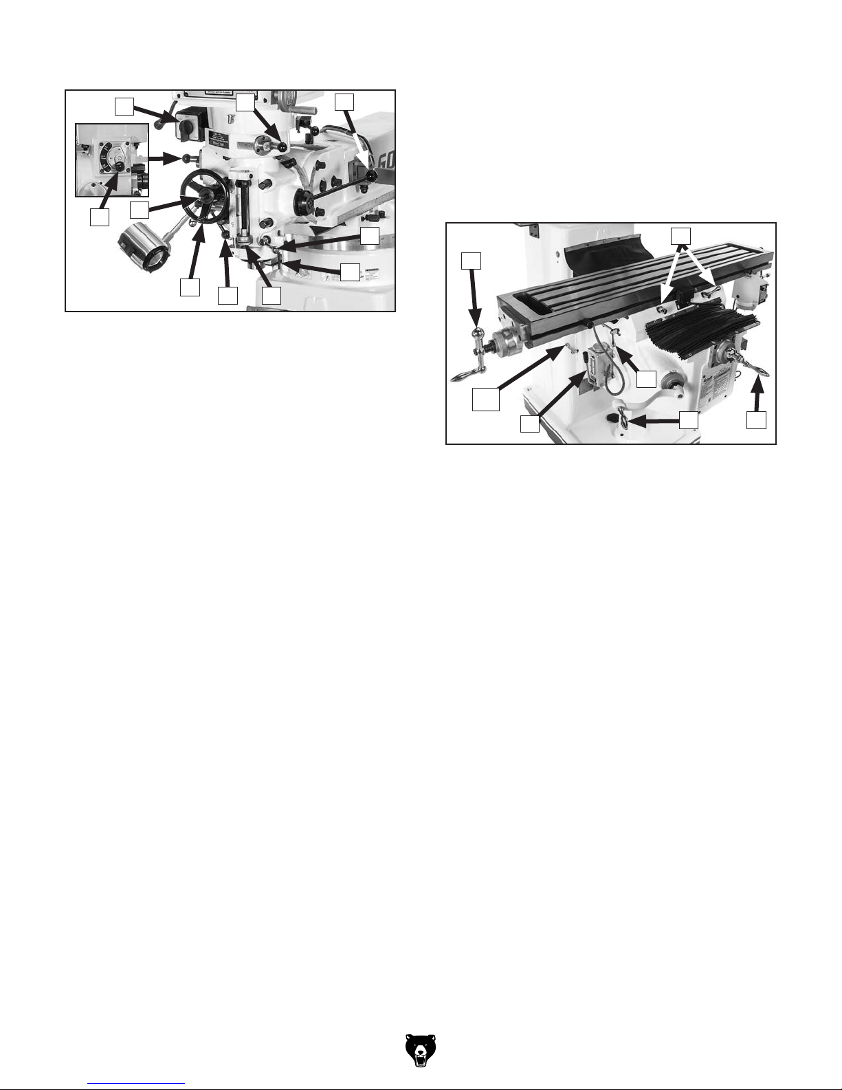
Lower Headstock
K
T. Auto-Downfeed Rate Selector: Selects one
L
M
of the three auto-downfeed rates:
0.0015 in/rev
0.003 in/rev
0.006 in/rev
S
T
N
O
R
Figure 3. Lower headstock controls and
components (Model G0797 shown).
K. Spindle Switch: Controls forward/reverse
direction of spindle rotation.
Note: Spindle switch direction settings will
be reversed in low range due to back gear.
Therefore, in low range, FORWARD will cause
reverse spindle rotation, and REVERSE will
cause forward rotation.
L. Manual/Power Downfeed Selector: Selects
between manual and power downfeed.
M. Coarse Downfeed Lever: Quickly moves
quill downward manually and automatically
retracts spindle to top position when released.
Typically used for drilling operations.
PQ
Table
V
U
Y
AA
Z
Figure 4. Table controls and components.
U. X-Axis Ball Handle: Manually moves table
along X-axis (left and right).
V. X-Axis Locks: Tightens to prevent X-axis
table movement for increased rigidity during operations where the X-axis should not
move.
W. Y-Axis Ball Handle: Manually moves table
along Y-axis (front and back).
X
W
N. Quill Lock Lever: Locks quill in vertical posi-
tion.
O. Dial Indicator Rod: Used to hold dial test
indicator when tramming spindle.
P. Adjustable Downfeed Stop: Limits depth of
quill travel. Dial is graduated in increments of
0.001". Typically used for repeat operations.
Q. Fine/Auto Downfeed Clutch Lever:
Engages fine/auto-downfeed gears.
R. Fine Downfeed Handwheel: Manually con-
trols slow spindle downfeed for fine Z-axis
control.
S. Auto-Downfeed Direction Pin: Starts, stops,
and reverses auto-downfeed direction.
Model G0796/G0797 (Mfd. Since 1/18)
X. Knee Crank: Manually moves table along
Z-axis (up and down).
Y. Y-Axis Lock: Tightens to prevent Y-axis
table movement for increased rigidity during operations where the Y-axis should not
move.
Z. One Shot Oiler: Lubricates X-, Y-, and
Z-axis table ways.
AA. Z-Axis Lock (1 of 2): Tightens to prevent
Z-axis table movement for increased rigidity
during operations where the Z-axis should
not move.
-7-
Page 10
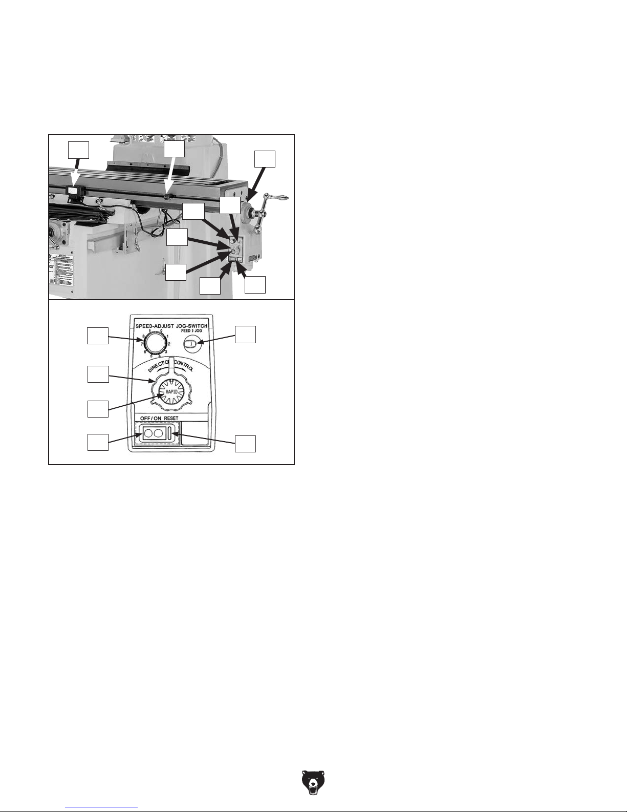
X-Axis Power Feed Identification
The mill is equipped with a power feed unit for
X-axis table movement. Refer to Figure 5 and the
descriptions below to understand the functions of
the various components of the power feed system.
AB. Power Feed Limit Switch: Stops table
movement when either of the switch side
plungers are pressed by limit stops.
AC. Limit Stop: Restricts table movement by its
positioning along front of table.
AB
AF
AG
AH
AI
AC
AG
AH
AF
AI
AE
AE
AJ
AJ
AD
AD. Graduated Index Ring: Displays distance of
table travel in 0.001" increments, with one full
revolution equal to 0.200" of table travel.
AE. Feed/Jog Switch: In left (feed) position, it
enables power feed to operate normally.
While pressing switch to right (jog position),
table moves in selected direction until switch
is released.
In middle position ("0"), table movement is
disabled.
AF. Speed Dial: Controls speed of power feed.
Rotating dial clockwise causes table to move
faster.
AG. Direction Knob: Selects direction of table
movement. Middle position is neutral.
AH. Rapid Traverse Button: When pressed,
moves table at full speed when already in
motion.
Figure 5. X-axis power feed controls.
AI. ON/OFF Button: Turns power feed ON and
OFF.
AJ. Circuit Breaker Reset Button: Resets inter-
nal circuit breaker if unit is overloaded and
shuts down.
-8-
Model G0796/G0797 (Mfd. Since 1/18)
Page 11

MACHINE DATA
SHEET
Customer Service #: (570) 546-9663 · To Order Call: (800) 523-4777 · Fax #: (800) 438-5901
MODEL G0796 9" X 49" VERTICAL MILL WITH POWER FEED
AND DRO
Product Dimensions:
Weight............................................................................................................................................................ 2249 lbs.
Width (side-to-side) x Depth (front-to-back) x Height........................................................................... 83 x 62 x 84 in.
Footprint (Length x Width)............................................................................................................................ 41 x 27 in.
Shipping Dimensions:
Type.......................................................................................................................................................... Wood Crate
Content........................................................................................................................................................... Machine
Weight............................................................................................................................................................ 2580 lbs.
Length x Width x Height....................................................................................................................... 60 x 55 x 80 in.
Must Ship Upright................................................................................................................................................... Yes
Electrical:
Power Requirement........................................................................................................... 220V, Single-Phase, 60 Hz
Full-Load Current Rating..................................................................................................................................... 13.8A
Minimum Circuit Size.............................................................................................................................................. 20A
Connection Type....................................................................................................................................... Cord & Plug
Power Cord Included.............................................................................................................................................. Yes
Recommended Power Cord................................................................................ "S" Type, 3-Wire, 12 AWG, 300VAC
Plug Included........................................................................................................................................................... No
Recommended Plug Type..................................................................................................................................... 6-20
Switch Type........................................................................................................................... Forward/Reverse Switch
Motors:
Main
Horsepower................................................................................................................................................ 3 HP
Phase............................................................................................................................................ Single-Phase
Amps......................................................................................................................................................... 13.8A
Speed................................................................................................................................................ 1720 RPM
Type........................................................................................................................................... TEFC Induction
Power Transfer ............................................................................................................................... V-Belt Drive
Bearings..................................................................................................... Shielded & Permanently Lubricated
Model G0796/G0797 (Mfd. Since 1/18)
-9-
Page 12

Main Specifications:
Operation Info
Spindle Travel.............................................................................................................................................. 5 in.
Max Distance Spindle to Column............................................................................................................... 21 in.
Max Distance Spindle to Table............................................................................................................ 15-7/8 in.
Longitudinal Table Travel (X-Axis)............................................................................................................. 28 in.
Longitudinal Leadscrew (X-Axis)............................................................................................................... 52 in.
Cross Table Travel (Y-Axis)....................................................................................................................... 12 in.
Vertical Table Travel (Z-Axis).................................................................................................................... 16 in.
Ram Travel................................................................................................................................................ 12 in.
Turret or Column Swivel (Left /Right)................................................................................................... 360 deg.
Head Tilt (Left/Right).............................................................................................................................. 90 deg.
Head Tilt (Front/Back)............................................................................................................................ 45 deg.
Drilling Capacity for Cast Iron................................................................................................................ 1-1/2 in.
Drilling Capacity for Steel...................................................................................................................... 1-1/4 in.
End Milling Capacity.................................................................................................................................... 1 in.
Face Milling Capacity................................................................................................................................... 3 in.
Table Info
Table Length.............................................................................................................................................. 49 in.
Table Width.................................................................................................................................................. 9 in.
Table Thickness.................................................................................................................................... 3-3/4 in.
Number of T-Slots............................................................................................................................................ 3
T-Slot Size................................................................................................................................................ 5/8 in.
T-Slots Centers...................................................................................................................................... 2-1/2 in.
Number of Longitudinal Feeds.............................................................................................................. Variable
X-Axis Table Power Feed Rate..................................................................................................... 0 – 3.41 FPM
X/Y-Axis Travel per Handwheel Revolution.......................................................................................... 0.200 in.
Z-Axis Travel per Handwheel Revolution............................................................................................. 0.100 in.
Spindle Info
Spindle Taper............................................................................................................................................... R-8
Number of Vertical Spindle Speeds.................................................................................................................. 8
Range of Vertical Spindle Speeds............................................................................................. 80 – 2720 RPM
Quill Diameter........................................................................................................................................ 3-3/8 in.
Quill Feed Rates.................................................................................................... 0.0015, 0.003, 0.006 in./rev.
Drawbar Thread Size............................................................................................................................. 7/16-20
Drawbar Length................................................................................................................................... 18-1/2 in.
Spindle Bearings................................................................................................ Angular Contact Ball Bearings
Construction
Spindle Housing/Quill........................................................................................................................... Cast Iron
Table.................................................................................................................................................... Cast Iron
Head.................................................................................................................................................... Cast Iron
Column/Base....................................................................................................................................... Cast Iron
Base..................................................................................................................................................... Cast Iron
Stand.................................................................................................................................................... Cast Iron
Paint Type/Finish.................................................................................................................................... Enamel
Other Specifications:
Country of Origin ................................................................................................................................................ China
Warranty ........................................................................................................................................................... 1 Year
Approximate Assembly & Setup Time ........................................................................................................ 90 Minutes
Serial Number Location .................................................................................................................................. ID Label
ISO 9001 Factory .................................................................................................................................................. Yes
-10 -
Model G0796/G0797 (Mfd. Since 1/18)
Page 13

MACHINE DATA
SHEET
Customer Service #: (570) 546-9663 · To Order Call: (800) 523-4777 · Fax #: (800) 438-5901
MODEL G0797 10" X 50" VARIABLE‐SPEED VERTICAL MILL
WITH POWER FEED AND DRO
Product Dimensions:
Weight............................................................................................................................................................ 2470 lbs.
Width (side-to-side) x Depth (front-to-back) x Height......................................................................... 100 x 85 x 88 in.
Footprint (Length x Width)............................................................................................................................ 48 x 33 in.
Shipping Dimensions:
Type.......................................................................................................................................................... Wood Crate
Content........................................................................................................................................................... Machine
Weight............................................................................................................................................................ 3021 lbs.
Length x Width x Height....................................................................................................................... 62 x 61 x 82 in.
Must Ship Upright................................................................................................................................................... Yes
Electrical:
Power Requirement.................................................................................................................... 220V, 3-Phase, 60Hz
Full-Load Current Rating....................................................................................................................................... 8.6A
Minimum Circuit Size.............................................................................................................................................. 15A
Connection Type....................................................................................................................................... Cord & Plug
Power Cord Included.............................................................................................................................................. Yes
Recommended Power Cord................................................................................. "S" Type, 4-Wire, 14AWG, 300VAC
Plug Included........................................................................................................................................................... No
Recommended Plug Type................................................................................................................................... 15-15
Switch Type........................................................................................................................... Forward/Reverse Switch
Motors:
Main
Horsepower................................................................................................................................................ 3 HP
Phase.................................................................................................................................................... 3-Phase
Amps........................................................................................................................................................... 8.6A
Speed................................................................................................................................................ 1720 RPM
Type........................................................................................................................................... TEFC Induction
Power Transfer ............................................................................................................................... V-Belt Drive
Bearings..................................................................................................... Shielded & Permanently Lubricated
Model G0796/G0797 (Mfd. Since 1/18)
-11-
Page 14

Main Specifications:
Operation Info
Spindle Travel.............................................................................................................................................. 5 in.
Max Distance Spindle to Column........................................................................................................ 27-1/2 in.
Max Distance Spindle to Table............................................................................................................ 19-1/4 in.
Longitudinal Table Travel (X-Axis)............................................................................................................. 30 in.
Longitudinal Leadscrew (X-Axis)............................................................................................................... 52 in.
Cross Table Travel (Y-Axis)....................................................................................................................... 14 in.
Vertical Table Travel (Z-Axis).................................................................................................................... 15 in.
Ram Travel.......................................................................................................................................... 18-1/2 in.
Turret or Column Swivel (Left /Right)................................................................................................... 360 deg.
Head Tilt (Left/Right).............................................................................................................................. 90 deg.
Head Tilt (Front/Back)............................................................................................................................ 45 deg.
Drilling Capacity for Cast Iron................................................................................................................ 1-1/2 in.
Drilling Capacity for Steel...................................................................................................................... 1-1/4 in.
End Milling Capacity.................................................................................................................................... 1 in.
Face Milling Capacity................................................................................................................................... 3 in.
Table Info
Table Length.............................................................................................................................................. 50 in.
Table Width................................................................................................................................................ 10 in.
Table Thickness.................................................................................................................................... 4-1/8 in.
Number of T-Slots............................................................................................................................................ 3
T-Slot Size................................................................................................................................................ 5/8 in.
T-Slots Centers...................................................................................................................................... 2-1/2 in.
Number of Longitudinal Feeds.............................................................................................................. Variable
X-Axis Table Power Feed Rate..................................................................................................... 0 – 3.41 FPM
X/Y-Axis Travel per Handwheel Revolution.......................................................................................... 0.200 in.
Z-Axis Travel per Handwheel Revolution............................................................................................. 0.100 in.
Spindle Info
Spindle Taper............................................................................................................................................... R-8
Number of Vertical Spindle Speeds...................................................................................................... Variable
Range of Vertical Spindle Speeds............................................................................................. 60 – 4200 RPM
Quill Diameter...................................................................................................................................... 3-5/16 in.
Quill Feed Rates................................................................................................... 0.0015, 0.003, 0.006, in./rev.
Drawbar Thread Size............................................................................................................................. 7/16-20
Drawbar Length................................................................................................................................... 18-1/2 in.
Spindle Bearings....................................................................................................... Angular Contact Bearings
Construction
Spindle Housing/Quill........................................................................................................................... Cast Iron
Table.................................................................................................................................................... Cast Iron
Head.................................................................................................................................................... Cast Iron
Column/Base....................................................................................................................................... Cast Iron
Base..................................................................................................................................................... Cast Iron
Paint Type/Finish.................................................................................................................................... Enamel
Other Specifications:
Country of Origin ................................................................................................................................................ China
Warranty ........................................................................................................................................................... 1 Year
Approximate Assembly & Setup Time ........................................................................................................ 90 Minutes
Serial Number Location .................................................................................................................................. ID Label
ISO 9001 Factory .................................................................................................................................................. Yes
-12-
Model G0796/G0797 (Mfd. Since 1/18)
Page 15

SECTION 1: SAFETY
For Your Own Safety, Read Instruction
Manual Before Operating This Machine
The purpose of safety symbols is to attract your attention to possible hazardous conditions.
This manual uses a series of symbols and signal words intended to convey the level of importance of the safety messages. The progression of symbols is described below. Remember that
safety messages by themselves do not eliminate danger and are not a substitute for proper
accident prevention measures. Always use common sense and good judgment.
Indicates an imminently hazardous situation which, if not avoided,
WILL result in death or serious injury.
Indicates a potentially hazardous situation which, if not avoided,
COULD result in death or serious injury.
Indicates a potentially hazardous situation which, if not avoided,
MAY result in minor or moderate injury. It may also be used to alert
against unsafe practices.
This symbol is used to alert the user to useful information about
NOTICE
proper operation of the machine.
Safety Instructions for Machinery
OWNER’S MANUAL. Read and understand this
owner’s manual BEFORE using machine.
TRAINED OPERATORS ONLY. Untrained operators have a higher risk of being hurt or killed.
Only allow trained/supervised people to use this
machine. When machine is not being used, disconnect power, remove switch keys, or lock-out
machine to prevent unauthorized use—especially
around children. Make your workshop kid proof!
DANGEROUS ENVIRONMENTS. Do not use
machinery in areas that are wet, cluttered, or have
poor lighting. Operating machinery in these areas
greatly increases the risk of accidents and injury.
MENTAL ALERTNESS REQUIRED. Full mental
alertness is required for safe operation of machinery. Never operate under the influence of drugs or
alcohol, when tired, or when distracted.
ELECTRICAL EQUIPMENT INJURY RISKS. You
can be shocked, burned, or killed by touching live
electrical components or improperly grounded
machinery. To reduce this risk, only allow qualified
service personnel to do electrical installation or
repair work, and always disconnect power before
accessing or exposing electrical equipment.
DISCONNECT POWER FIRST.
nect machine from power supply BEFORE making
adjustments, changing tooling, or servicing machine.
This prevents an injury risk from unintended startup
or contact with live electrical components.
EYE PROTECTION. Always wear ANSI-approved
safety glasses or a face shield when operating or
observing machinery to reduce the risk of eye
injury or blindness from flying particles. Everyday
eyeglasses are NOT approved safety glasses.
Always discon-
Model G0796/G0797 (Mfd. Since 1/18)
-13-
Page 16

WEARING PROPER APPAREL. Do not wear
clothing, apparel or jewelry that can become
entangled in moving parts. Always tie back or
cover long hair. Wear non-slip footwear to reduce
risk of slipping and losing control or accidentally
contacting cutting tool or moving parts.
HAZARDOUS DUST. Dust created by machinery
operations may cause cancer, birth defects, or
long-term respiratory damage. Be aware of dust
hazards associated with each workpiece material. Always wear a NIOSH-approved respirator to
reduce your risk.
HEARING PROTECTION. Always wear hearing protection when operating or observing loud
machinery. Extended exposure to this noise
without hearing protection can cause permanent
hearing loss.
REMOVE ADJUSTING TOOLS. Tools left on
machinery can become dangerous projectiles
upon startup. Never leave chuck keys, wrenches,
or any other tools on machine. Always verify
removal before starting!
USE CORRECT TOOL FOR THE JOB. Only use
this tool for its intended purpose—do not force
it or an attachment to do a job for which it was
not designed. Never make unapproved modifications—modifying tool or using it differently than
intended may result in malfunction or mechanical
failure that can lead to personal injury or death!
AWKWARD POSITIONS. Keep proper footing
and balance at all times when operating machine.
Do not overreach! Avoid awkward hand positions
that make workpiece control difficult or increase
the risk of accidental injury.
CHILDREN & BYSTANDERS. Keep children and
bystanders at a safe distance from the work area.
Stop using machine if they become a distraction.
GUARDS & COVERS. Guards and covers reduce
accidental contact with moving parts or flying
debris. Make sure they are properly installed,
undamaged, and working correctly BEFORE
operating machine.
FORCING MACHINERY. Do not force machine.
It will do the job safer and better at the rate for
which it was designed.
NEVER STAND ON MACHINE. Serious injury
may occur if machine is tipped or if the cutting
tool is unintentionally contacted.
STABLE MACHINE. Unexpected movement during operation greatly increases risk of injury or
loss of control. Before starting, verify machine is
stable and mobile base (if used) is locked.
USE RECOMMENDED ACCESSORIES. Consult
this owner’s manual or the manufacturer for recommended accessories. Using improper accessories will increase the risk of serious injury.
UNATTENDED OPERATION. To reduce the
risk of accidental injury, turn machine OFF and
ensure all moving parts completely stop before
walking away. Never leave machine running
while unattended.
MAINTAIN WITH CARE. Follow all maintenance
instructions and lubrication schedules to keep
machine in good working condition. A machine
that is improperly maintained could malfunction,
leading to serious personal injury or death.
DAMAGED PARTS. Regularly inspect machine
for damaged, loose, or mis-adjusted parts—or
any condition that could affect safe operation.
Immediately repair/replace BEFORE operating
machine. For your own safety, DO NOT operate
machine with damaged parts!
MAINTAIN POWER CORDS. When disconnecting cord-connected machines from power, grab
and pull the plug—NOT the cord. Pulling the cord
may damage the wires inside. Do not handle
cord/plug with wet hands. Avoid cord damage by
keeping it away from heated surfaces, high traffic
areas, harsh chemicals, and wet/damp locations.
EXPERIENCING DIFFICULTIES. If at any time
you experience difficulties performing the intended operation, stop using the machine! Contact our
Technical Support at (570) 546-9663.
-14-
Model G0796/G0797 (Mfd. Since 1/18)
Page 17

Additional Safety for Milling Machines
You can be seriously injured or killed by getting clothing, jewelry, or long hair entangled with
rotating cutter/spindle. You can be severely cut or have fingers amputated from contact with
rotating cutters. You can be blinded or struck by broken cutting tools, metal chips, workpieces,
or adjustment tools thrown from the rotating spindle with great force. To reduce your risk of
serious injury when operating this machine, completely heed and understand the following:
UNDERSTAND ALL CONTROLS. Make sure
you understand the function and proper use of all
controls before starting. This will help you avoid
making mistakes that result in serious injury.
AVOIDING ENTANGLEMENT. DO NOT wear
loose clothing, gloves, or jewelry, and tie back
long hair. Keep all guards in place and secure.
Always allow spindle to stop on its own. DO NOT
stop spindle using your hand or any other object.
WEAR FACE SHIELD. Always wear a face shield
in addition to safety glasses. This provides more
complete protection for your face than safety
glasses alone.
USE CORRECT SPINDLE SPEED. Follow recommended speeds and feeds for each size and
type of cutting tool. This helps avoid tool breakage
during operation and ensures best cutting results.
INSPECT CUTTING TOOL. Inspect cutting tools
for sharpness, chips, or cracks before each use.
Replace dull, chipped, or cracked cutting tools
immediately.
PROPERLY SECURE CUTTER. Firmly secure
cutting tool or drill bit so it does not fly out of spindle during operation.
POWER DISRUPTION. In the event of a local
power outage during operation, turn spindle
switch OFF to avoid a possible sudden startup
once power is restored.
CLEAN MACHINE SAFELY. Metal chips or shavings can be razor sharp. DO NOT clear chips
by hand or compressed air that can force chips
farther into machine—use a brush or vacuum
instead. Never clear chips while spindle is turning.
SECURE WORKPIECE TO TABLE. Clamp workpiece to table or secure in a vise mounted to table,
so workpiece cannot unexpectedly shift or spin
during operation. NEVER hold workpiece by hand
during operation.
PROPERLY MAINTAIN MACHINE. Keep
machine in proper working condition to help
ensure that it functions safely and all guards and
other components work as intended. Perform routine inspections and all necessary maintenance.
Never operate machine with damaged or worn
parts that can break or result in unexpected movement during operation.
DISCONNECT POWER FIRST. To reduce risk of
electrocution or injury from unexpected startup,
make sure mill/drill is turned OFF, disconnected
from power, and all moving parts have come to
a complete stop before changing cutting tools or
starting any inspection, adjustment, or maintenance procedure.
REMOVE CHUCK KEY & SPINDLE TOOLS.
Always remove chuck key, drawbar wrench, and
other tools used on the spindle immediately after
use. This will prevent them from being thrown by
the spindle upon startup.
Model G0796/G0797 (Mfd. Since 1/18)
-15-
Page 18

SECTION 2: POWER SUPPLY
Before installing the machine, consider the availability and proximity of the required power supply
circuit. If an existing circuit does not meet the
requirements for this machine, a new circuit must
be installed. To minimize the risk of electrocution,
fire, or equipment damage, installation work and
electrical wiring must be done by an electrician or
qualified service personnel in accordance with all
applicable codes and standards.
or equipment damage
may occur if machine is
not properly grounded
and connected to power
The full-load current rating is the amperage a
machine draws at 100% of the rated output power.
On machines with multiple motors, this is the
amperage drawn by the largest motor or sum of all
motors and electrical devices that might operate
at one time during normal operations.
The full-load current is not the maximum amount
of amps that the machine will draw. If the machine
is overloaded, it will draw additional amps beyond
the full-load rating.
If the machine is overloaded for a sufficient length
of time, damage, overheating, or fire may result—
especially if connected to an undersized circuit.
To reduce the risk of these hazards, avoid overloading the machine during operation and make
sure it is connected to a power supply circuit that
meets the specified circuit requirements.
For your own safety and protection of
Note: Circuit requirements in this manual apply to
a dedicated circuit—where only one machine will
be running on the circuit at a time. If machine will
be connected to a shared circuit where multiple
machines may be running at the same time, consult an electrician or qualified service personnel to
ensure circuit is properly sized for safe operation.
A power supply circuit includes all electrical
equipment between the breaker box or fuse panel
in the building and the machine. The power supply circuit used for this machine must be sized to
safely handle the full-load current drawn from the
machine for an extended period of time. (If this
machine is connected to a circuit protected by
fuses, use a time delay fuse marked D.)
This machine MUST be grounded. In the event
of certain malfunctions or breakdowns, grounding
reduces the risk of electric shock by providing a
path of least resistance for electric current.
Improper connection of the equipment-grounding
wire can result in a risk of electric shock. The
wire with green insulation (with or without yellow
stripes) is the equipment-grounding wire. If repair
or replacement of the power cord or plug is necessary, do not connect the equipment-grounding
wire to a live (current carrying) terminal.
Check with a qualified electrician or service personnel if you do not understand these grounding
requirements, or if you are in doubt about whether
the tool is properly grounded. If you ever notice
that a cord or plug is damaged or worn, disconnect it from power, and immediately replace it with
a new one.
Availability
Electrocution, fire, shock,
supply.
Full-Load Current Rating
Circuit Information
property, consult an electrician if you are
unsure about wiring practices or electrical
codes in your area.
G0796 Full-Load Current Rating .... 13.8 Amps
G0797 Full-Load Current Rating ...... 8.6 Amps
-16 -
Grounding Requirements
Model G0796/G0797 (Mfd. Since 1/18)
Page 19
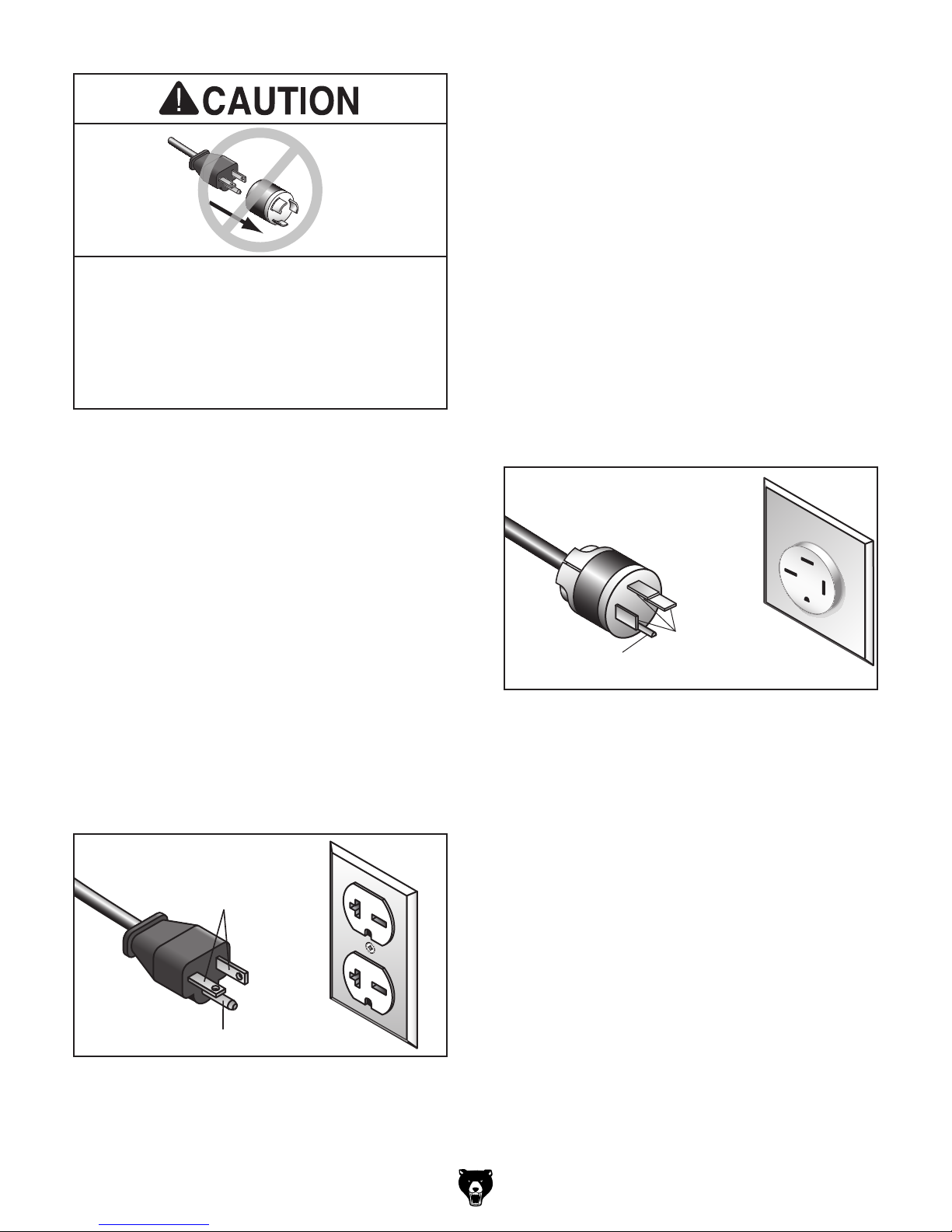
This machine is prewired to operate on a power
supply circuit that has a verified ground and meets
the following requirements:
No adapter should be used with plug. If
plug does not fit available receptacle, or if
machine must be reconnected for use on a
This machine is prewired to operate on a power
supply circuit that has a verified ground and meets
the following requirements:
The power cord and plug used on this machine
must have an equipment-grounding wire and
grounding prong. The plug must only be inserted
into a matching receptacle (outlet) that is properly installed and grounded in accordance with all
local codes and ordinances (see figure below).
The power cord and plug used on this machine
must have an equipment-grounding wire and
grounding prong. The plug must only be inserted
into a matching receptacle (outlet) that is properly installed and grounded in accordance with all
local codes and ordinances (see figure below).
We do not recommend using an extension cord
with this machine.
cord, only use it if absolutely necessary and only
on a temporary basis.
Extension cords cause voltage drop, which can
damage electrical components and shorten motor
life. Voltage drop increases as the extension cord
size gets longer and the gauge size gets smaller
(higher gauge numbers indicate smaller sizes).
Any extension cord used with this machine must
be in good condition and contain a ground wire
and matching plug/receptacle. Additionally, it must
meet the following size requirements:
different type of circuit, reconnection must
be performed by an electrician or qualified
service personnel, and it must comply with
all local codes and ordinances.
G0796 Circuit Requirements
G0797 Circuit Requirements
Nominal Voltage .........208V, 220V, 230V, 240V
Cycle ..........................................................60 Hz
Phase .................................................... 3-Phase
Power Supply Circuit ......................... 15 Amps
Plug/Receptacle ............................NEMA 15-15
Cord ........“ S ”-Ty p e , 4-Wire, 14 AWG, 300 VAC
GROUNDED
15-15 RECEPTACLE
Nominal Voltage .........208V, 220V, 230V, 240V
Cycle ..........................................................60 Hz
Phase .................................................... 1-Phase
Power Supply Circuit ......................... 20 Amps
Plug/Receptacle ............................. NEMA 6-20
Cord ........“ S”-Typ e , 3-Wire, 12 AWG, 300 VAC
GROUNDED
6-20 RECEPTACLE
Current Carrying Prongs
6-20 PLUG
15-15 PLUG
Current
Carrying
Grounding Prong
Prongs
Figure 7. Typical 15-15 plug and receptacle.
Extension Cords
If you must use an extension
Figure 6. Typical 6-20 plug and receptacle.
Model G0796/G0797 (Mfd. Since 1/18)
Grounding Prong
Minimum Gauge Size (G0796) ............12 AWG
Minimum Gauge Size (G0797) .............14 AWG
Maximum Length (Shorter is Better).......50 ft.
-17-
Page 20
SECTION 3: SETUP
This machine was carefully packaged for safe
transport. When unpacking, separate all enclosed
items from packaging materials and inspect them
for shipping damage.
,
please
IMPORTANT:
you are completely satisfied with the machine and
have resolved any issues between Grizzly or the
shipping agent. You MUST have the original pack-
aging to file a freight claim. It is also extremely
helpful if you need to return your machine later.
Keep children and pets away
from plastic bags or packing
materials shipped with this
get help from other people
The following items are needed, but not included,
for the setup/assembly of this machine.
Needed for Setup
This machine presents
serious injury hazards
to untrained users. Read
through this entire manual to become familiar with
the controls and operations before starting the
machine!
Wear safety glasses during
the entire setup process!
Description Qty
• Wrench or Socket 14mm ............................ 1
• Precision Level ........................................... 1
• Safety Glasses (for each person) ............... 1
• Solvent/Cleaner .......................................... 1
• Shop Rags .................................................. 1
• Brass Hammer ........................................... 1
• Lifting Straps (Rated min. 3000 lbs.) .......... 2
• Lifting Equipment (Rated min. 3000 lbs.) ... 1
• Additional People ....................................... 2
HEAVY LIF T!
Straining or crushing injury
may occur from improperly
lifting machine or some of
its parts. To reduce this risk,
and use a forklift (or other
lifting equipment) rated for
weight of this machine.
No list of safety guidelines can be complete.
Every shop environment is different. Always
consider safety first, as it applies to your
individual working conditions. Use this and
other machinery with caution and respect.
Failure to do so could result in serious personal injury, damage to equipment, or poor
work results.
Unpacking
If items are damaged
call us immediately at (570) 546-9663.
Save all packaging materials until
SUFFOCATION HAZARD!
machine. Discard immediately.
-18-
Model G0796/G0797 (Mfd. Since 1/18)
Page 21
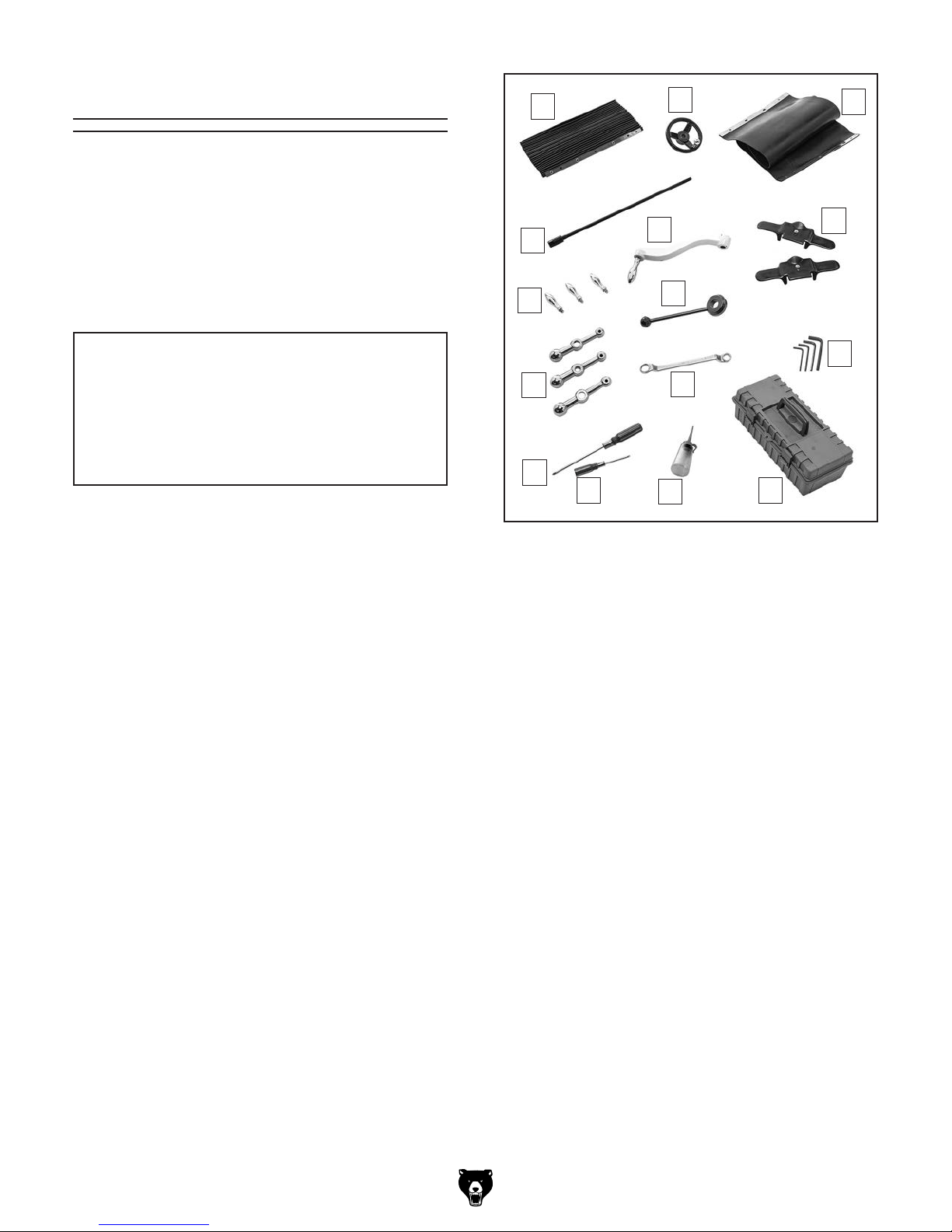
Inventory
The following is a list of items shipped with your
machine. Before beginning setup, lay these items
out and inventory them.
If any non-proprietary parts are missing (e.g. a
nut or a washer), we will gladly replace them; or
for the sake of expediency, replacements can be
obtained at your local hardware store.
A
B
C
NOTICE
If you cannot find an item on this list, carefully check around/inside the machine and
packaging materials. Often, these items get
lost in packaging materials while unpacking or they are pre-installed at the factory.
Small Item Inventory (Figure 8) Qty
A. Front Way Cover ......................................... 1
B. Fine Downfeed Handwheel ........................ 1
C. Rear Way Cover ......................................... 1
D. Drawbar ...................................................... 1
E. Knee Crank ................................................ 1
F. Belt Housing Safety Covers (G0796) ......... 2
G. Revolving Handles ..................................... 3
H. Coarse Downfeed Lever ............................. 1
I. Ball Handles ............................................... 3
J. Closed-End Wrench 17/19mm .................... 1
K. Hex Wrench Set 4, 5, 6, 8MM ...............1 Ea
L. Phillips Screwdriver #2 ............................... 1
M. Slotted Screwdriver #2 ............................... 1
N. Bottle for Oil ............................................... 1
O. Toolbox ....................................................... 1
G
D
I
L
M
Figure 8. Small item inventory.
E
H
J
N
F
K
O
Model G0796/G0797 (Mfd. Since 1/18)
-19 -
Page 22
The unpainted surfaces of your machine are
coated with a heavy-duty rust preventative that
prevents corrosion during shipment and storage.
This rust preventative works extremely well, but it
will take a little time to clean.
Be patient and do a thorough job cleaning your
machine. The time you spend doing this now will
give you a better appreciation for the proper care
of your machine's unpainted surfaces.
There are many ways to remove this rust preventative, but the following steps work well in a wide
variety of situations. Always follow the manufacturer’s instructions with any cleaning product you
use and make sure you work in a well-ventilated
area to minimize exposure to toxic fumes.
Before cleaning, gather the following:
• Disposable rags
• Cleaner/degreaser (WD•40 works well)
• Safety glasses & disposable gloves
• Plastic paint scraper (optional)
Basic steps for removing rust preventative:
1.
2.
3.
4.
Many cleaning solvents
work in a well-ventilated
Avoid chlorine-based solvents, such as
Cleanup
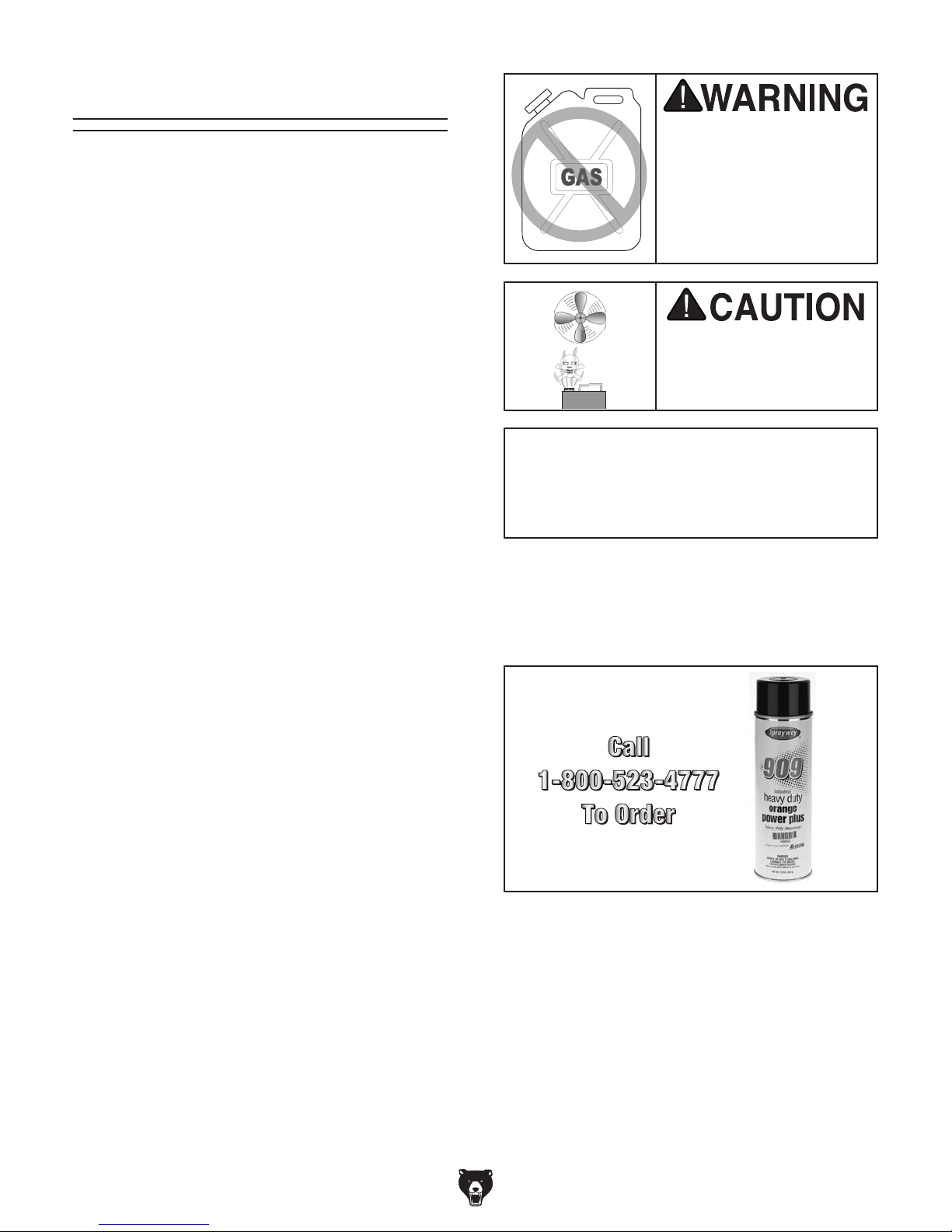
Gasoline and petroleum
products have low flash
points and can explode
or cause fire if used to
clean machinery. Avo i d
using these products
to clean machinery.
Put on safety glasses.
Coat the rust preventative with a liberal
amount of cleaner/degreaser, then let it soak
for 5–10 minutes.
Wipe off the surfaces. If your cleaner/degreas-
er is effective, the rust preventative will wipe
off easily. If you have a plastic paint scraper,
scrape off as much as you can first, then wipe
off the rest with the rag.
Repeat Steps 2–3 as necessary until clean,
then coat all unpainted surfaces with a quality
metal protectant to prevent rust.
are toxic if inhaled. Only
area.
NOTICE
acetone or brake parts cleaner, that may
damage painted surfaces.
T23692—Orange Power Degreaser
A great product for removing the waxy shipping grease from the non-painted parts of the
machine during clean up.
Figure 9. T23692 Orange Power Degreaser.
-20-
Model G0796/G0797 (Mfd. Since 1/18)
Page 23
Site Considerations
Weight Load
Refer to the
of your machine. Make sure that the surface upon
which the machine is placed will bear the weight
of the machine, additional equipment that may be
installed on the machine, and the heaviest workpiece that will be used. Additionally, consider the
weight of the operator and any dynamic loading
that may occur when operating the machine.
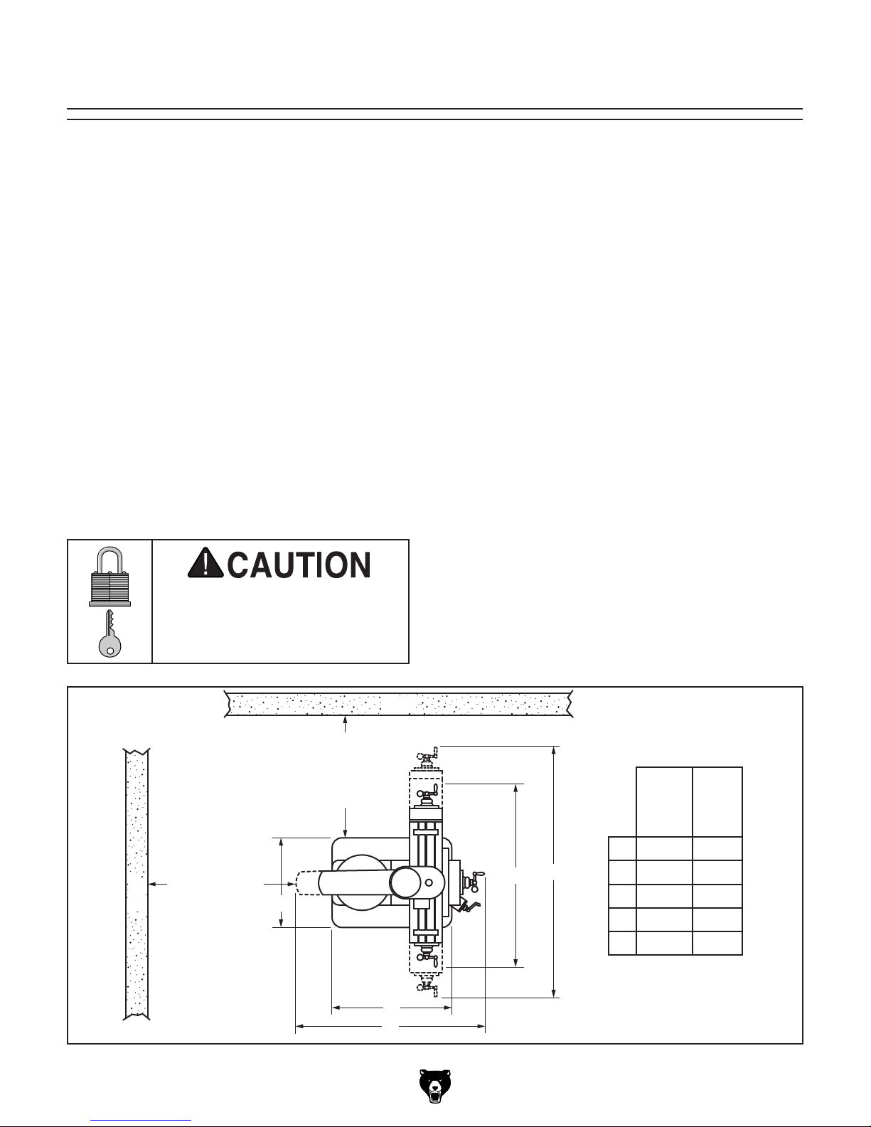
Space Allocation
Consider the largest size of workpiece that will
be processed through this machine and provide
enough space around the machine for adequate
operator material handling or the installation of
auxiliary equipment. With permanent installations,
leave enough space around the machine to open
or remove doors/covers as required by the maintenance and service described in this manual.
See below for required space allocation.
Physical Environment
Extreme conditions for this type of machinery are
Place this machine near an existing power source.
other hazards. Make sure to leave enough space
Shadows, glare, or strobe effects that may distract
Machine Data Sheet for the weight
Children or untrained people
may be seriously injured by
this machine. Only install in an
access restricted location.
30"
Minimum
Clearance
for Maintenance
30"
Minimum
Clearance for
Wall
Maintenance
E
The physical environment where the machine is
operated is important for safe operation and longevity of machine components. For best results,
operate this machine in a dry environment that is
free from excessive moisture, hazardous chemicals, airborne abrasives, or extreme conditions.
generally those where the ambient temperature
range exceeds 41°–104°F; the relative humidity
range exceeds 20%–95% (non-condensing); or
the environment is subject to vibration, shocks,
or bumps.
Electrical Installation
Make sure all power cords are protected from
traffic, material handling, moisture, chemicals, or
around machine to disconnect power supply or
apply a lockout/tagout device, if required.
Lighting
Wall
Lighting around the machine must be adequate
enough that operations can be performed safely.
or impede the operator must be eliminated.
G0796
A
99" 100"
A
B
B
C
D
E
67" 67"
61" 74"
35" 39"
24" 25"
G0797
Figure 10. Minimum working clearances.
Model G0796/G0797 (Mfd. Since 1/18)
D
C
-21-
Page 24
Lifting & Placing
get help from other people
HEAVY LIF T!
Straining or crushing injury
may occur from improperly
lifting machine or some of
its parts. To reduce this risk,
and use a forklift (or other
lifting equipment) rated for
weight of this machine.
Use a forklift and at least two other people (see
Page 18) to lift the machine off the pallet and onto
a suitable location.
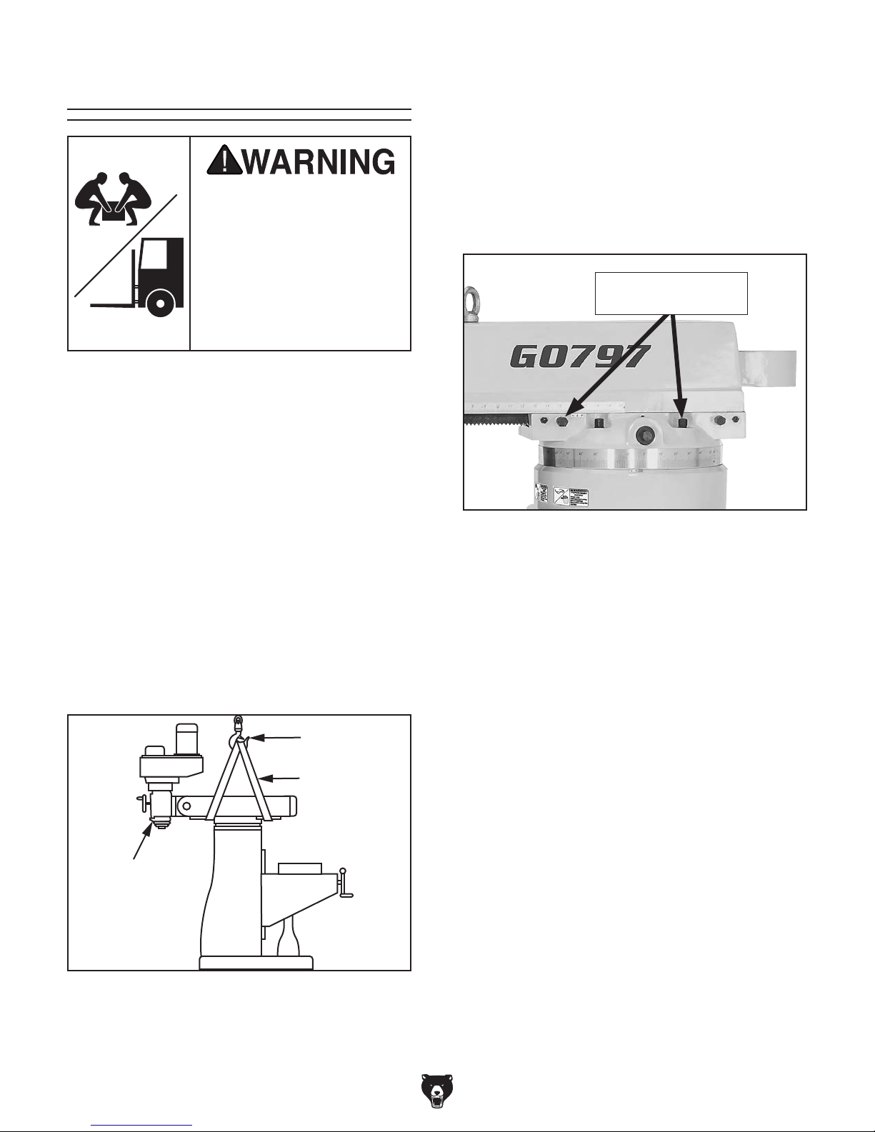
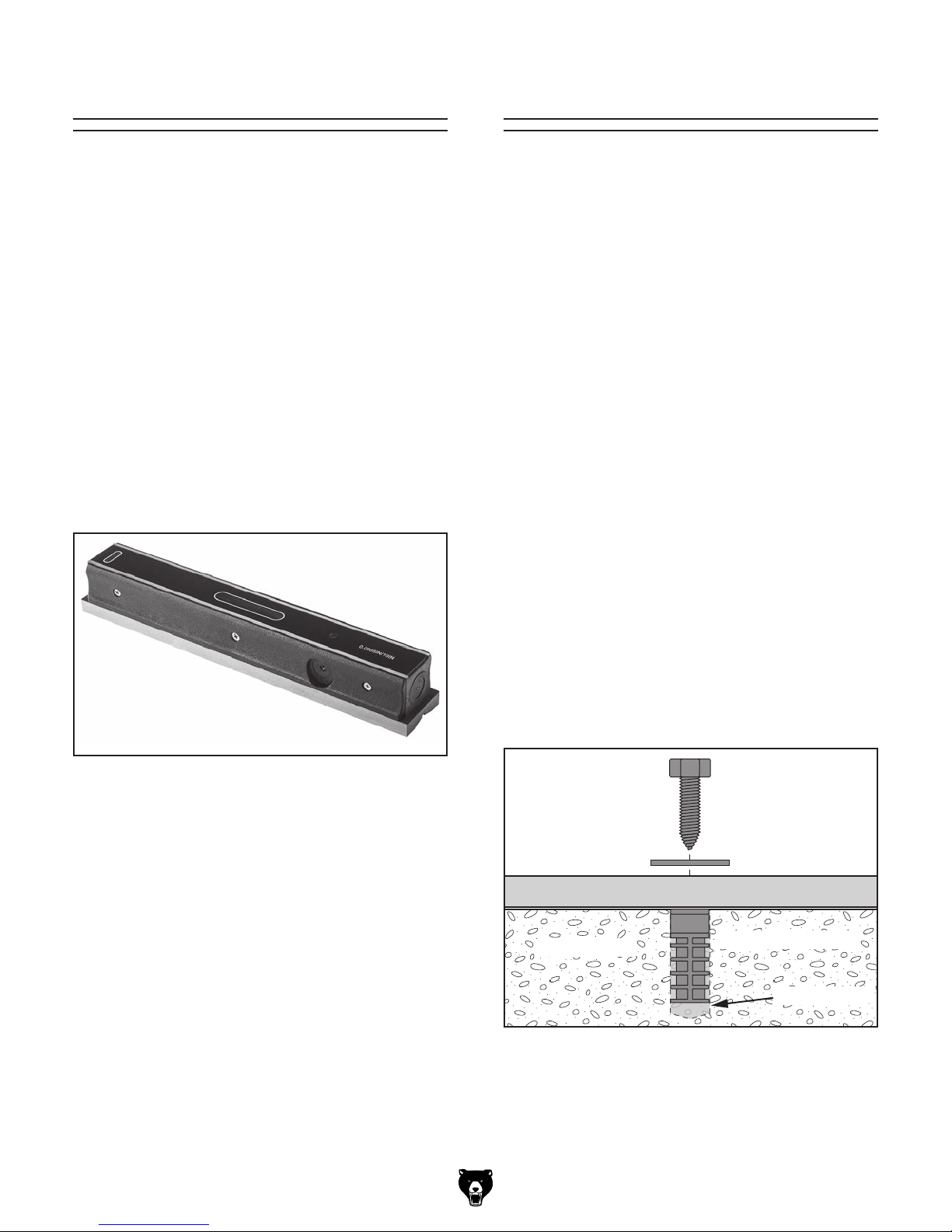
To lift and move mill:
Note: After re-positioning ram and head-
stock, make sure they are locked in place to
prevent unexpected movement during lifting.
Make sure the four turret lock bolts (two on
each side of the ram, see Figure 12) are
torqued to 47 ft./lbs. to keep the ram from
unexpectedly moving from the force of the
lifting straps.
Turret Locking Bolts
(2 of 4)
1. Remove crate from shipping pallet, then
with mill still on pallet, move to installation
location.
2. Rotate ram 180° so headstock is facing
backwards (see Figure 11), then rotate head
upright.
Refer to Positioning Head on Page 32 and
Positioning Ram on Page 33 for detailed
instructions to help with this step.
Safety Hook
Lifting Straps
Headstock
Facing Backward
Figure 12. Locations of turret locking bolts.
3. Place lifting straps under ram and con-
nect them to safety hook, as illustrated in
Figure 11.
Note: Place protective material between
straps and mill to protect ram and ways, and
to keep from cutting lifting straps.
4. Unbolt mill from shipping pallet.
5. With other people steadying load to keep it
from swaying, lift mill a couple of inches.
— If mill tips to one side, lower it to the
ground and adjust ram or table to balance
the load. Make sure to re-tighten lock
levers and bolts before lifting mill again.
— If mill lifts evenly, remove shipping pallet
and lower mill onto its prepared location.
Figure 11. Illustrated example of using lifting
straps to move the mill.
-22-
Model G0796/G0797 (Mfd. Since 1/18)
Page 25
Anchoring machinery to the floor prevents tipping
or shifting and reduces vibration that may occur
during operation, resulting in a machine that runs
slightly quieter and feels more solid.
If the machine will be installed in a commercial or
workplace setting, or if it is permanently connected (hardwired) to the power supply, local codes
may require that it be anchored to the floor.
If not required by any local codes, fastening the
machine to the floor is an optional step. If you
choose not to do this with your machine, we recommend placing it on machine mounts, as these
provide an easy method for leveling and they have
vibration-absorbing pads.
Lag shield anchors with lag screws (see below)
are a popular way to anchor machinery to a concrete floor, because the anchors sit flush with the
floor surface, making it easy to unbolt and move
the machine later, if needed. However, anytime
local codes apply, you MUST follow the anchoring
methodology specified by the code.
Leveling
Anchoring to Floor
Leveling machinery helps precision components,
such as dovetail ways, remain straight and flat
during the lifespan of the machine. Components
on an unleveled machine may slowly twist due to
the dynamic loads placed on the machine during
operation.
Use metal shims between the base and the floor
when leveling the machine.
For best results, use a precision level that is at
least 12" long and sensitive enough to show a
distance movement when a 0.003" shim (approximately the thickness of one sheet of standard
newspaper) is placed under one end of the level.
See Figure 13 for an example of a high precision
level provided by Grizzly.
Number of Mounting Holes ............................ 4
Diameter of Mounting Holes .......................
5
⁄8"
Anchoring to Concrete Floors
Figure 13. Model H2683 12" Master Machinist's
Model G0796/G0797 (Mfd. Since 1/18)
Level.
Lag Screw
Flat Washer
Machine Base
Concrete
Figure 14. Popular method for anchoring
machinery to a concrete floor.
Lag Shield Anchor
Drilled Hole
-23-
Page 26
Assembly
The machine must be fully assembled before it
can be operated. Before beginning the assembly
process, refer to
and gather
all
To ensure the assembly process
goes smoothly, first clean any
covered or coated in heavy-duty rust preventative (if
applicable).
Needed for Setup
listed items.
parts that are
Assembly of the mill consists of installing the
loose components listed in the inventory section.
This will take approximately 15 minutes.
3. Slide Z-axis crank onto end of Z-axis
leadscrew, as shown in Figure 16.
Z-Axis
Crank
To assemble mill:
1. Remove ball handle nuts from X- and Y-axis
leadscrews, slide ball handles onto leadscrews, and secure with ball handle nuts (see
Figure 15).
Note: Tighten the ball handle nuts just until
they are snug. Overtightening could increase
the wear of the moving parts.
2. Thread revolving handles into small end of
ball handles (see Figure 15) and tighten
them with 14mm wrench.
Ball
Handle
Ball
Handle
Nut
Figure 16. Z-axis crank installed.
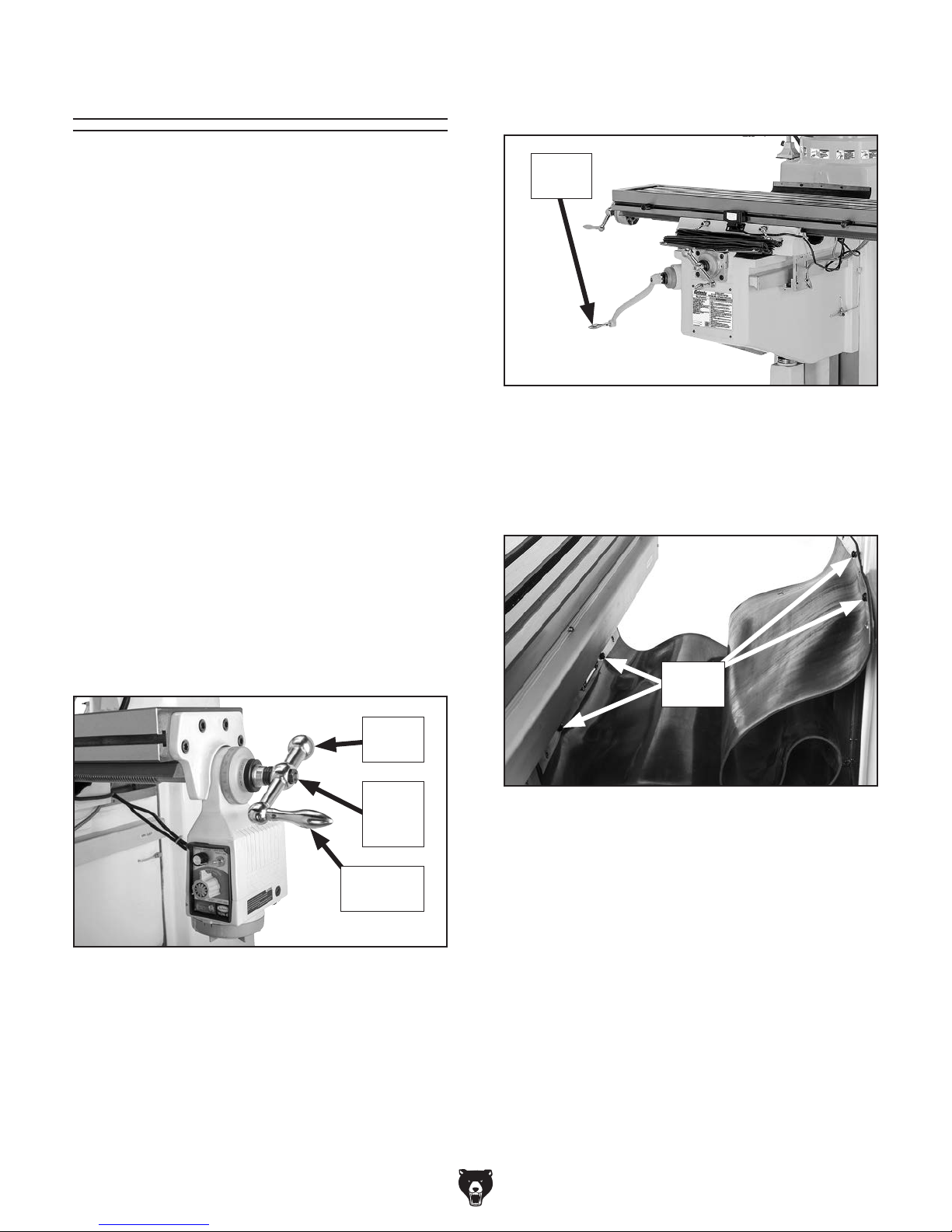
4. Move table all the way forward, using Y-axis
handwheel, then attach rear way cover with
four pre-installed cap screws, as shown in
Figure 17.
Cap
Screws
Figure 17. Rear way cover installed.
Revolving
Handle
Figure 15. Ball handle installed on X-axis
leadscrew.
-24-
Model G0796/G0797 (Mfd. Since 1/18)
Page 27
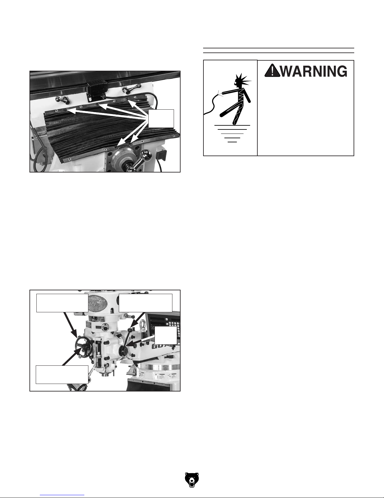
5. Move table all the way back toward the
Before the machine can be connected to the
power source, an electrical circuit and connection device must be prepared per the POWER
SUPPLY section in this manual, and all previous setup instructions in this manual must be
complete to ensure that the machine has been
assembled and installed properly.
column, then attach front way cover with
five pre-installed cap screws, as shown in
Figure 18.
Cap
Screws
Figure 18. Front way cover installed.
6. Install coarse downfeed lever (see Figure 19),
making sure pin on back of lever seats in
hub, then use a 4mm hex wrench to tighten
set screw.
Power Connection
Electrocution or fire
may occur if machine is
ungrounded, incorrectly
connected to power, or
connected to an undersized
circuit. Use an electrician
or a qualified service
personnel to ensure a safe
power connection.
7. Use a Phillips head screwdriver to remove
auto-downfeed direction pin from hub, then
mount fine downfeed handwheel on hub,
making sure pin on back of handwheel seats
in hub, and secure with auto-downfeed direction pin (see Figure 19).
Fine Downfeed
Handwheel
Auto-Downfeed
Direction Pin
Figure 19. Downfeed controls installed.
Coarse
Downfeed Lever
Set
Screw
Always make sure the power switch on the
machine is turned OFF (or the OFF button is
pushed in) before connecting power.
Power Connection
Insert power cord plug into a matching power supply receptacle. The machine is now connected to
the power source.
If you need to disconnect the machine from power
later, pull the plug completely out of the receptacle.
Note About Extension Cords: Using an incor-
rectly sized extension cord may decrease the
life of electrical components on your machine.
Refer to Extension Cords on Page 17 for more
information.
Model G0796/G0797 (Mfd. Since 1/18)
-25-
Page 28
Test Run
setup instructions have been performed.
Operating an improperly set up machine
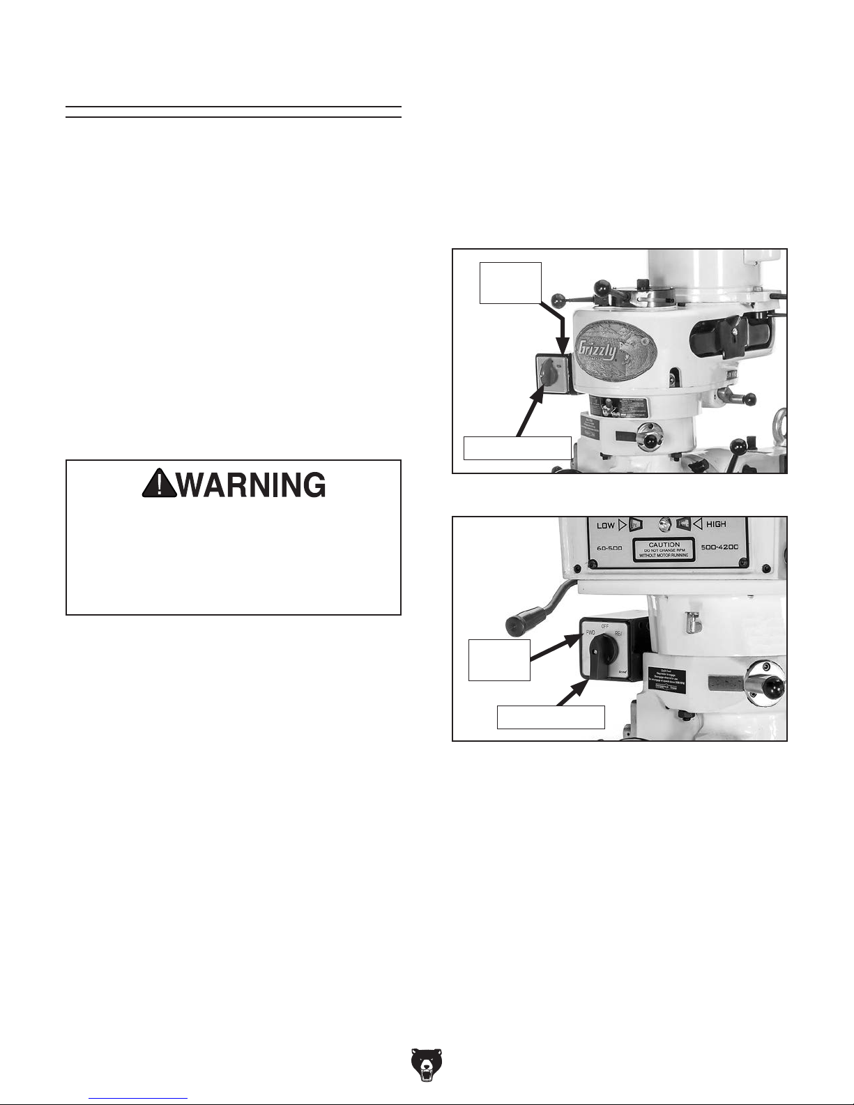
6. Rotate spindle switch to STOP (G0796) or
OFF (G0797) to avoid accidental startup in
Step 7.
Once assembly is complete, test run your machine
to make sure it runs properly and is ready for
regular operation.
The test run consists of verifying the following:
1) The motor powers up and runs correctly,
2) the spindle switch works correctly, and 3)
(G0797 only) the motor turns the correct direction
(machine is not wired out of phase).
If, during the test run, you cannot easily locate
the source of an unusual noise or vibration, stop
using the machine immediately, then review
Troubleshooting on Page 51.
If you still cannot remedy a problem, contact our
Tech Support at (570) 546-9663 for assistance.
DO NOT start machine until all preceding
7. Connect mill to power source specified in
POWER SUPPLY section on Page 17.
8. Rotate spindle switch to FOR (forward) posi-
tion (see Figure 20 or 21).
FOR
Position
Spindle Switch
Figure 20. Model G0796 spindle switch.
may result in malfunction or unexpected results that can lead to serious injury,
death, or machine/property damage.
Mill Test Run
1. Make sure you understand all safety instruc-
tions at beginning of manual and that machine
is set up properly.
2. Make sure all tools and objects used during
setup are cleared away from machine.
3. Make sure that mill is properly lubricated
(refer to Lubrication section on Page 47 for
specific details).
4. Set spindle speed to low range (refer to
Spindle Speed, beginning on Page 34 for
detailed instructions).
5. Move downfeed selector to manual (forward) position so that spindle does not automatically downfeed during this test (refer to
Downfeed Controls section on Page 37 for
detailed instructions).
FWD
Position
Spindle Switch
Figure 21. Model G0797 spindle switch.
9. Listen for abnormal noises and watch for
unexpected actions from mill. Machine should
run smoothly and without excessive vibration
or rubbing noises.
— Strange or unusual noises or actions must
be investigated immediately. Turn the
machine OFF and disconnect it from the
power source before investigating or correcting potential problems.
10. Rotate spindle switch to STOP (G0796) or
OFF (G0797) to stop spindle rotation.
-26-
Model G0796/G0797 (Mfd. Since 1/18)
Page 29

Power Feed Test Run
This mill comes with a power feed unit for X-axis
table travel. Proper operation of the limit switch
attached to the front middle of the table is
important to the operation of this power feed unit.
If the power feed does not operate as expected
during the following steps, disconnect it from
power and contact our Tech Support at (570) 5469663 for assistance.
5. Make sure power feed direction knob is in
neutral (middle) position, turn speed dial
counterclockwise to lowest setting, then
press ON button.
6. Turn direction knob to left, slowly turn speed
dial clockwise to increase speed, then confirm that table is moving to left.
7. Watch for table limit stop to hit limit switch
and turn power feed OFF, stopping table
movement.
During power feed operation, ball handles
spin rapidly when engaged. Always stay
clear of ball handles when using power
feed. Failure to do so could lead to entanglement or impact injuries.
To test run power feed:
1. Make sure all tools, cables, and other items
are well clear of table movement and potential
direction of travel.
2. Refer to Operating X-Axis Power Feed
section, beginning on Page 31, to understand
how power feed, table locks, and limit switch
function.
3. Loosen table locks on front of table.
4. Plug power feed power cord into a grounded
110V power outlet.
8. Turn direction knob through neutral (middle)
position and all the way to the right. Table
should begin moving to the right.
9. Confirm that table stops moving when limit
stop presses against limit switch plunger.
10. Move direction knob to neutral (middle) position, turn speed dial to lowest setting, and
press OFF button.
Congratulations! The Test Run of the mill is
complete. Continue to the next page to perform the Spindle Break-In and Inspections &
Adjustments procedures.
Model G0796/G0797 (Mfd. Since 1/18)
-27-
Page 30

The spindle break-in procedure distributes lubrication
reduce the risk
of early
if there are any "dry" spots
or areas where lubrication has settled in the bearings. You
placing
first time when the machine is new or if it has
been sitting idle for longer than 6 months.
Always start the spindle break-in at the lowest
speed to minimize wear if there
Allow the spindle to run long enough to warm up
and distribute the bearing grease, then incrementally increase spindle speeds and repeat this process at each speed until reaching the maximum
spindle speed. Following the break-in procedure
in this progressive manner helps minimize any
potential wear that could occur before lubrication
is fully distributed.
Spindle Break-In
tain the warranty. Failure to do this could
4. Repeat Step 3 for following speeds, pro-
gressing from lower to higher RPMs:
G0796: 210, 325 RPM
G0797: 250, 400 RPM
You must complete this procedure to main-
cause rapid wear-and-tear of spindle bearings once they are placed under load.
throughout the bearings to
bearing failure
must complete this procedure before
operational loads on the spindle for the
are dry spots.
5. Set spindle speed to high range, and repeat
Step 3 for following speeds, progressing from
lower to higher RPMs:
G0796: 660, 1715, 2720 RPM
G0797: 500, 2500, 4000 RPM
Note: Make sure to turn spindle OFF and
allow it to come to a complete stop before
switching direction and before changing
speed.
Congratulations, the spindle break-in is now
complete!
Since the mill head has been moved around
for shipping purposes, you will need to tram
the spindle with the table to ensure a 90°
alignment. Refer to the Tramming Spindle
section on Page 57 for detailed instructions.
To perform spindle break-in procedure:
1. Successfully perform all steps in Test Run
section beginning on Page 26.
2. Set spindle speed to low range (refer to
Spindle Speed, beginning on Page 34 for
detailed instructions).
Note: When operating in low range, spindle
will rotate in reverse when spindle switch is
set to FOR or FWD, and spindle will rotate in
forward when switch is set to reverse.
3. Run spindle in forward rotation at following
speed for 5 minutes, turn spindle OFF and
allow it to come to a complete stop, then
repeat in reverse rotation.
G0796: 80 RPM
G0797: 60 RPM
-28-
Inspections &
Adjustments
The following list of adjustments were performed
at the factory before the machine was shipped:
• Gib Adjustments ............................. Page 54
• Leadscrew Backlash
Adjustments .................................... Page 55
Be aware that machine components can shift
during the shipping process. Pay careful attention to these adjustments during operation of the
machine. If you find that the adjustments are not
set according to the procedures in this manual or
your personal preferences, re-adjust them.
Model G0796/G0797 (Mfd. Since 1/18)
Page 31

SECTION 4: OPERATIONS
The purpose of this overview is to provide the novice machine operator with a basic understanding
of how the machine is used during operation, so
the
discussed later
in this manual
Due to the generic nature of this overview, it is
not intended to be an instructional guide. To learn
more about specific operations, read this entire
manual,
training from experienced
machine operators
outside of this manual by reading "how-to" books,
trade magazines, or websites.
To reduce your risk of
serious injury, read this
entire manual BEFORE
Operation Overview
To complete a typical operation, the operator
does the following:
1. Examines workpiece to make sure it is suit-
able for milling.
machine controls/components
are easier to understand.
seek additional
, and do additional research
using machine.
To reduce risk of eye or face injury from
flying chips, always wear approved safety
glasses and a face shield when operating
this machine.
2. Positions table according to operation and
size of workpiece.
3. Firmly clamps workpiece to table or a mill
vise.
4. Installs correct cutting tool for operation.
5. Uses manual downfeed and table controls to
correctly position cutting tool and workpiece
for operation. If X-axis power feed will be used
during operation, operator confirms speed
and length of table movement required.
6. Configures mill for correct spindle speed of
operation.
7. Puts on required safety glasses and face
shield, and makes sure workpiece and table
are clear of all tools, cords, and other items.
8. Turns mill ON by starting spindle rotation,
then performs operation.
9. Turns mill OFF.
If you are not experienced with this type
of machine, WE STRONGLY RECOMMEND
that you seek additional training outside of
this manual. Read books/magazines or get
formal training before beginning any projects. Regardless of the content in this section, Grizzly Industrial will not be held liable
for accidents caused by lack of training.
Model G0796/G0797 (Mfd. Since 1/18)
-29-
Page 32

Positioning Table
The mill table moves in three directions, as illustrated in Figure 22:
• X-axis (longitudinal)
• Y-axis (cross)
• Z-axis (vertical)
These movements are controlled by rotating the
X- and Y-axis ball handles and the Z-axis crank.
Additionally, the table can be moved along the
X-axis with the power feed.
X-Axis or Longitudinal Travel
(Left & Right)
Y-Axis or
Cross Travel
(In & Out)
Z-Axis or
Vertical Elevation
(Up & Down)
Figure 22. The directions of table movement.
Graduated Index Rings
The table ball handles and knee crank have graduated index rings (see Figure 23) that are used
to determine table movement in the increments
listed below:
Index Rings
Figure 23. Locations of index rings.
Table Locks
Use table locks to increase the rigidity of the table
when movement in that direction is not required
for the operation.
Refer to Figure 24 to identify the locks for each
table axis.
X-Axis Locks
Z-Axis
Lock
(1 of 2)
Figure 24. Locations of table locks for each axis.
Y-Axis
Lock
Axis
X 0.001" 0.200"
Y 0.001" 0.200"
Z 0.001" 0.10 0"
-30-
Individual
Increment
One Full
Revolution
Always keep table locked in place unless
table movement is required for your operation. Unexpected table and workpiece
movement could cause cutter to bind
with workpiece, which may ruin cutter or
workpiece.
Model G0796/G0797 (Mfd. Since 1/18)
Page 33

Table Limit Stops
Two adjustable table limit stops are located at
each end of the table (see Figure 25). They limit
automatic table movement by pressing the table
limit switch, which stops the X-axis power feed
unit.
4. With your hand poised over ON/OFF button
in case you need to suddenly turn unit OFF,
move direction knob to select desired direction of table travel.
5. Use speed dial to slowly bring speed of
movement up to desired rate.
To adjust the position of the limit stops, loosen
the cap screws securing the stops, reposition, and
tighten securely. If not being used, position stops
at far ends of table so as not to interfere with table
movement.
Operating X-Axis Power Feed
Tool Needed Qty
Hex Wrench 8mm .............................................. 1
To operate X-axis power feed:
1. Loosen X-axis locks.
2. Turn speed dial (see Figure 25) all the way
counterclockwise to slowest setting.
3. Move direction knob to neutral (middle)
position, press feed/jog switch to left (feed
position), then push ON/OFF button (see
Figure 25).
To jog table, move Feed/Jog switch (see
Figure 25) to right (Jog) position. Table will
move in selected direction until switch is
released.
To cause table to instantly move at full speed
when already in motion, press the rapid
traverse button (see Figure 25). The table
will resume previous speed when button is
released.
6. When you are finished using power feed:
a. Turn unit OFF.
b. Rotate speed dial all the way counter-
clockwise.
c. Move direction knob to neutral (middle)
position to avoid unexpected table movement later.
Limit
Switch
Limit Stop
(1 of 2)
Speed
Dial
Direction
Knob
ON/OFF
Button
Figure 25. Location of X-axis power feed
controls.
Feed/Jog
Switch
Rapid
Traverse
Button
For additional component details, refer to X-Axis
Power Feed Identification
on Page 8.
Model G0796/G0797 (Mfd. Since 1/18)
-31-
Page 34

Positioning
Headstock
The head tilts 45° forward or backward and
rotates 90° left or right (see Figures 26–27).
Any time the head has been tilted or rotated, you
must tram the spindle with the table when setting
the headstock back to the 90° position. This is the
only way to ensure precision milling results later.
Refer to Tramming Spindle, on Page 57 for more
information.
45°
Tools Needed Qty
Wrench 19mm ................................................... 1
Wrench 17mm (G0796)...................................... 1
Tilting Head Forward/Backward
1. DISCONNECT MACHINE FROM POWER!
2. Loosen three lock bolts shown in Figure 28.
3. Use one hand to apply pressure to head
in direction of tilt, then slowly rotate tilt-bolt
shown in Figure 28.
Note: Rotate tilt-bolt clockwise to tilt head
backward and counterclockwise to tilt it
forward.
Tilt-Bolt
Figure 26. Head tilted 45° backward.
90°
Figure 27. Head rotated to the left.
The head is heavy. When tilting or rotating
head, get help to support its weight as you
make adjustments.
Lock
Bolts
Figure 28. Head tilt controls.
4. Re-tighten lock bolts.
-32-
Model G0796/G0797 (Mfd. Since 1/18)
Page 35

Rotating Head Left/Right
1. DISCONNECT MACHINE FROM POWER!
Positioning Ram
2. Loosen four lock bolts shown in Figure 29.
3. Use one hand to apply pressure to head in
direction of rotation, then slowly turn rotation
bolt shown in Figure 29.
Note: Turn rotation bolt clockwise to rotate
head left and counterclockwise to rotate it
right.
Rotation Bolt
Lock Bolts
The ram rotates 360° around the turret, and
travels forward or backward 12" (G0796), or 18
(G0797).
Tool Needed Qty
Wrench 19mm ................................................... 1
1
⁄2 "
Rotating Ram
1. DISCONNECT MACHINE FROM POWER!
2. Loosen four lock bolts on top of turret (see
Figure 30).
Note: There are two lock bolts on each side
of the ram.
Lock Bolts
(2 of 4)
Figure 29. Head rotation controls.
Note: The lock bolts shown in Figure 29 are
threaded into T-nuts that travel in a circular slot during head rotation. When rotating
head, it is possible for these T-nuts to jam in
the slot preventing movement of head. If this
happens, gently rotate each lock bolt, starting with the lower right, until you free up the
jammed T-nut. Then continue to rotate head
to desired position.
4. Re-tighten lock bolts.
Always lock head firmly in place after tilting or rotating it. Unexpected movement of
head during operations could cause damage to cutter or workpiece.
Rotation
Scale
Figure 30. Ram rotational controls.
Note: In the next step, take care not to entan-
gle or stretch electrical cabling as you move
ram around turret.
3. Push head to manually rotate ram. Use rotation scale to determine correct position for
your operation, then re-tighten four lock bolts
to secure ram in place.
Model G0796/G0797 (Mfd. Since 1/18)
-33-
Page 36

Moving Ram Forward/Backward
Many variables affect the optimum spindle speed
to use for any given operation
important are the recommended cutting speed for
the workpiece material and the diameter of the
cutting tool, as noted below.
Using the correct spindle speed is important for
safe and satisfactory results
ing tool life.
To set the spindle speed for your operation, you
will need to:
spindle speed
for the cutting task, and 2) configure the spindle
controls to match the closest spindle speed.
Cutting speed, typically defined in feet per minute
(FPM), is the speed at which the edge of a tool
moves across the material surface.
The "R
varies
depending on the type of workpiece material. It is
the
in order to
optimize tool life
The books
Machine
Shop Practice
vide excellent recommendations for which cutting
speeds to use when calculating the spindle speed.
The
also provide a wealth of additional
information about the variables that affect cutting
speed and
Also, there are a large number of easy-to-use
spindle speed calculators that can be found on
the internet. These sources will help you take into
account all applicable variables to determine the
best spindle speed for the operation.
1. DISCONNECT MACHINE FROM POWER!
2. Loosen two lock bolts shown in Figure 31.
Lock Bolts
Spindle Speed
, as well as maximiz-
1) Determine the best
Determining Spindle Speed
Adjustment
Bolt
Figure 31. Ram forward/backward movement
controls.
3. Make sure there are no obstructions to
ram travel, especially any tooling around
workpiece, then slowly rotate adjustment bolt
to move ram.
Note: Rotate bolt clockwise to move ram
away from table and counterclockwise to
move ram toward table.
4. Re-tighten lock bolts.
Always lock ram firmly in place after moving
it. Unexpected movement of ram and head
during operations could damage cutter or
workpiece.
, but the two most
*Recommended
Cutting Speed (FPM) x 12
Tool Dia. (in inches) x 3.14
Spindle
=
Speed
(RPM)
*Double if using carbide cutting tool
Figure 32. Spindle speed formula for milling.
ecommended Cutting Speed"
ideal speed for cutting that material
and produce a desirable finish.
-34-
Machinery’s Handbook or
, and some internet sites, pro-
se sources
they are a good educational resource.
Model G0796/G0797 (Mfd. Since 1/18)
Page 37

Setting G0796 Spindle Speed
The Model G0796 has eight spindle speeds—four
in low motor speed and four in high motor speed.
Setting the spindle speed involves: 1) Selecting
the spindle speed range, 2) positioning the V-belt,
and 3) setting the spindle switch.
To set Model G0796 spindle speed:
1. DISCONNECT MACHINE FROM POWER!
2. Use chart below or spindle speed chart on
headstock to find appropriate spindle speed
for your operation (see Figure 33).
4. Move range lever shown in Figure 34 to
HIGH or LOW position.
Range
Lever
High Low
3. Pull spindle speed range selector knob (see
Figure 33) out, position in HIGH or LOW
range, then release knob to seat knob pin in
detent.
Note: If it is difficult to move range selector
knob, rotate spindle by hand to help mesh
gears until selector moves freely.
Model G0796 Spindle Speed Ranges
Low Range 80, 135, 210, & 325 RPM
High Range 660, 1110, 1750, & 2720 RPM
Spindle Speed
Range Selector Knob
Spindle Speed
Chart
Figure 34. Model G0796 range lever.
5. Firmly grasp spindle, then quickly rotate it
back and forth until you hear/feel front pulley
drop into spindle clutch.
— If this step was not successful, use HIGH-
LOW range lever to re-set speed range,
then repeat this step until you are certain
that spindle is seated into spindle clutch.
6. Remove belt housing side covers on either
side of head to expose V-belt and pulleys, as
shown in Figure 35.
7. Loosen two motor lock levers, one on each
side of head, then pull belt tension adjustment lever forward to release V-belt tension
(see Figure 35).
Adjustment Lever
Figure 33. Model G0796 available spindle
speeds, location of spindle speed chart, and
range selector knob in the HIGH position.
Model G0796/G0797 (Mfd. Since 1/18)
Lock Lever
(1 of 2)
V-Belt & Pulley
Access
Figure 35. Model G0796 V-belt and pulleys
exposed for setting spindle speed.
-35-
Page 38

8. Refer to spindle speed chart on front of head-
G H
Lever 1
Lever 2
E
F
HIGH/LOW RANGE SELECTION
HIGH RANGE: 1E, 2H
Place Lever 2 in position G, then move
Lever 1 to position E. Turn belt by hand
until pulley locks into place, then move
Lever 2 to position H.
LOW RANGE: 1F, 2G
Place Lever 1 in position F and Lever 2 in
position G.
Changing HIGH/LOW range will
reverse spindle rotation.
stock (see Figure 36), and position V-belt on
pulleys for desired spindle speed.
SPINDLE SPEED CHART
1
2
3
4
SPINDLE PULLEY MOTOR PULLEY
To set Model G0797 spindle speed:
1. Make sure spindle is completely stopped,
then use chart below to find spindle speed
range that includes required spindle speed
for your operation (see Figure 37).
2. Pull spindle speed range selector knob (see
Figure 37) out, move to HIGH or LOW posi-
tion, then release knob to seat knob pin in
detent.
SPEED
RANGE
LOW
HIGH
BELT POSITION
1
80
660
135
1110
2
3
210
1750
4
325
2720
Figure 36. Model G0796 spindle speed chart.
9. Push adjustment lever backward with moder-
ate force to re-tension V-belt, then re-tighten
two lock levers to secure motor (see Figure
35 on Page 35).
10. Replace two belt housing side covers before
re-connecting mill to power.
To avoid entanglement hazards, always
ensure belt housing safety covers are firmly
in place before connecting the mill to power.
Note: If it is difficult to move range selector
knob, rotate spindle by hand to help mesh
gears until selector moves freely.
Model G0797 Spindle Speed Ranges
Low Range 60–500 RPM
High Range 500–4200 RPM
Spindle Speed
Range Selector Knob
Figure 37. Model G0797 available spindle
speeds and location of range selector knob.
Setting G0797 Spindle Speed
The Model G0797 has variable spindle speeds
from 60 to 4200 RPM. Setting the spindle speed
involves 1) Selecting the spindle speed range,
and 2) using the variable-speed handwheel to
select the spindle speed.
For Model G0797 ONLY, always make sure
that spindle rotation has started and is at
a constant speed before using variablespeed handwheel to adjust spindle speed.
Otherwise, moving parts inside belt housing could be damaged and void warranty.
-36-
3. Use spindle switch to start spindle rotation.
4. Slowly rotate variable-speed handwheel
shown in Figure 38 until desired speed is dis-
played in indicator for speed range selected.
High-Low Range
Speed Indicators
Variable-Speed
Handwheel
Figure 38. Location of Model G0797 variable-
Model G0796/G0797 (Mfd. Since 1/18)
speed controls.
Page 39

Spindle Downfeed
E. Downfeed Scale. Used with the downfeed
stop and quill dog, shows the depth of spindle
downfeed in inches.
Spindle downfeed movement on the mill is controlled by three mechanisms: 1) The coarse
downfeed lever, 2) the fine downfeed handwheel,
and 3) the auto-downfeed system.
Downfeed Controls
Use Figure 39 and the following descriptions to
become familiar with the spindle downfeed controls.
When spindle rotation is reversed, either
by changing the spindle speed range or by
using the spindle direction switch, the direction of spindle auto-downfeed will reverse.
A
B
K
F. Downfeed Stop Locking Wheel. Tightens
against downfeed stop to lock it in place.
G. Downfeed Stop. Sets the depth of spindle
downfeed. The stop is threaded into position,
then the locking wheel is used to secure it in
place.
H. Quill Lock Lever. Secures the quill in place
for increased stability during operations.
I. Quill Dog. Moves with the quill and spindle.
When it contacts the downfeed stop in coarse
and auto downfeed modes, it disengages
the downfeed clutch and the spindle autoretracts.
J. Coarse Downfeed Lever. Manually controls
quick spindle downfeed.
K. Downfeed Selector. Sets the mill for manual
downfeed or auto-downfeed control.
C
D
E
Figure 39. Downfeed controls.
A. Auto-Downfeed Rate Selector. Selects one
of the three auto-downfeed rates:
0.0015 in/rev
0.003 in/rev
0.006 in/rev
B. Fine Downfeed Handwheel. Manually con-
trols slow spindle downfeed.
C. Auto-Downfeed Direction Pin. Starts, stops,
and reverses the auto-downfeed direction.
GFH
J
I
Setting Downfeed Stop
The downfeed stop (see Figure 39) sets the depth
of spindle travel for repeat operations. The upper
edge of the downfeed stop aligns with marks on
the downfeed scale to help you set the approximate depth, however the downfeed scale functions as a general guide only, and is not intended
for low-tolerance, precision results.
To set the downfeed stop, rotate stop until upper
edge aligns with desired depth indicated on
scale (see Figure 39), then tighten locking wheel
against stop to secure it.
D. Fine Downfeed Clutch Lever. Engages the
fine/auto-downfeed gears.
Model G0796/G0797 (Mfd. Since 1/18)
-37-
Page 40

Auto-Downfeed
(Engaged)
Using Coarse Downfeed
Coarse downfeed is typically used for drilling,
because it allows you to quickly lower the spindle
with varying speed/pressure, and it automatically retracts the spindle to the top position when
released.
Note: To maintain control of the upward spindle
travel and the rotating bit in your workpiece,
always continue holding the lever until the spindle
returns to the top position. Letting go of the lever
too soon will cause the spindle to retract too
quickly and slam up into the headstock.
To use coarse downfeed:
3. Make sure pin of coarse downfeed lever
hub is engaged with one of the detents on
downfeed sleeve, and loosen quill lock lever
(see Figure 41).
4. Rotate coarse downfeed lever around hub to
control spindle depth.
Coarse Downfeed
Lever Hub & Sleeve
1. DISCONNECT MACHINE FROM POWER!
2. Make sure spindle is completely stopped,
then pull downfeed selector out and rotate it
until it seats in manual (disengaged) position
(see Figure 40).
Note: It may be necessary to turn the spindle
by hand as you move the selector to enable
the gears to mesh.
Manual
(Disengaged)
Downfeed
Selector
Quill Lock
Lever
Figure 41. Coarse downfeed lever hub,
downfeed sleeve, and quill lock.
Figure 40. Downfeed selector in manual
(disengaged) position.
-38-
Model G0796/G0797 (Mfd. Since 1/18)
Page 41

Using Fine Downfeed
Manual
(Disengaged)
Manual
(Disengaged)
Downfeed
Selector
Auto-Downfeed
(Engaged)
Fine downfeed is used for precise Z-axis positioning of a cutter or end-mill when milling a flat
surface across the face of a workpiece. In order
to ensure the milled surface remains flat, the quill
lock lever should be locked after each adjustment
to ensure the spindle height cannot move until the
entire milling operation is complete.
To use fine downfeed:
1. DISCONNECT MACHINE FROM POWER!
2. Make sure spindle is completely stopped,
then pull downfeed selector knob out and
rotate it until it seats in manual (disengaged)
position (see Figure 40 on Page 38).
Note: It may be necessary to turn the spindle
by hand as you move the selector to enable
the gears to mesh.
3. Set auto-downfeed direction pin (see Figure
39 on Page 37) in neutral (middle) position
to disengage fine downfeed handwheel from
auto-downfeed gears.
4. Use coarse downfeed lever to lower spindle
slightly until you can pull fine/auto downfeed
clutch lever (see Figure 39 on Page 37) to
the left so it locks in place.
Using Auto-Downfeed
When using the auto-downfeed system, the spindle will move in the direction you choose with the
auto-downfeed direction pin. When the quill dog
reaches the top or meets the downfeed stop, the
downfeed clutch lever will release. Then, if the
spindle was traveling upward, the movement will
simply stop. If the spindle was traveling downward, then the spindle will move back to the top
at a rate controlled by the return spring on the left
side of the head.
To use auto-downfeed:
1. Make sure spindle is completely stopped.
2. Pull downfeed selector knob out, then rotate
it clockwise until knob pin seats in auto-downfeed (engaged) detent (see Figure 42).
Note: It may be necessary to turn the spindle
by hand as you move the selector to enable
the gears to mesh.
Auto-Downfeed
Downfeed
Selector
(Engaged)
5. Rotate fine downfeed handwheel to raise or
lower spindle.
Model G0796/G0797 (Mfd. Since 1/18)
Figure 42. Downfeed selector in auto-downfeed
(engaged) position.
3. Position downfeed stop for spindle depth that
is correct for your operation, then secure it in
place with locking wheel (see Figure 39 on
Page 37 and description on Page 37).
-39-
Page 42

4. Position auto-downfeed direction pin (see
Fine/Auto Downfeed
(Engaged) Position
Figure 39 on Page 37) in center of handwheel
for spindle travel that is correct for your
operation. If necessary, rock fine downfeed
handwheel back-and-forth to move pin all the
way in or out.
Note: The direction pin has three positions:
1) In for one downfeed direction, 2) middle
for neutral or no movement, and 3) out for
the reverse direction. The direction of spindle
travel for the in and out positions is relative to
the direction of spindle rotation. Keep in mind
that spindle rotation and downfeed direction
will reverse when the spindle speed range is
changed.
5. Make sure fine/auto downfeed clutch lever
is all the way to right in disengaged position
(see Figure 43) so that spindle will not travel
when rotation is started.
6. Set mill for correct spindle speed, then begin
spindle rotation.
ALWAYS start spindle rotation before using
auto-downfeed to avoid risk of gear damage.
7. Select one of the three downfeed rates by
pulling knob of auto-downfeed rate selector
out, position selector over appropriate detent,
then release knob. Make sure pin is firmly
seated by attempting to move selector without pulling knob out.
Note: Refer to the illustration in Figure 44
when selecting the downfeed rate.
Coarse Downfeed
(Disengaged) Position
Figure 43. Fine/auto downfeed clutch lever
disengaged for auto-downfeed operations.
Note: We recommend that you complete
the remaining steps without a cutting tool
installed, without a workpiece in place, and
the table lower than the maximum spindle
downfeed travel. This will enable you to test
and confirm the settings before beginning the
actual cutting operation.
To avoid damage to system gearing, never
use auto-downfeed system with spindle
speeds over 1750 RPM.
Upper = 0.003 in./rev.
Middle = 0.0015 in./rev.
Lower = 0.006 in./rev.
(Rates given in inches of travel
per revolution of the spindle)
Figure 44. Positions of auto-downfeed rate
selector.
8. Use coarse downfeed lever to lower spindle
slightly until you can pull clutch lever out to
the left and it locks in place, which will start
auto-downfeed spindle travel.
-40-
Model G0796/G0797 (Mfd. Since 1/18)
Page 43

Spindle Brake
After turning the spindle switch OFF, move the
brake lever left or right (G0796) or up or down
(G0797) to bring the spindle to a full stop (see
Figures 45–46).
Loading/Unloading
Tooling
Each mill is equipped with an R-8 spindle taper
and a
7
⁄16"-20 spindle drawbar (see Figure 47).
To avoid premature wear of brake system,
use spindle brake ONLY after power to
spindle has been turned OFF.
G0796
Brake Lever
Figure 45. Model G0796 brake lever.
G0797
Brake Lever
G0797 Drawbar
G0796 Drawbar
Figure 47. Upper portions of drawbars.
Tools Needed Qty
Wrench 19mm ................................................... 1
Brass Hammer .................................................. 1
Loading Tooling
1. DISCONNECT MACHINE FROM POWER!
2. Clean any debris or oily substances from
inside spindle taper and mating surface of the
tooling.
Figure 46. Model G0797 brake lever.
To evenly wear brake shoes, alternate
direction you move lever when braking.
Model G0796/G0797 (Mfd. Since 1/18)
Note: Debris or oily substances can prevent
the tooling and spindle from properly mating.
This condition can cause excessive vibration,
poor cutting results, or tool/workpiece damage.
3. Place mill in low spindle speed range to keep
spindle from turning in next steps.
4. Align keyway of tool with protruding pin inside
spindle taper, firmly push tool into spindle to
seat it.
-41-
Page 44

5. With one hand holding tool in place, insert
drawbar into spindle from top of head, then
thread it into tool by hand until snug (see
Figure 48).
Figure 48. Drawbar loaded
(Model G0796 shown).
Unloading Tooling
1. DISCONNECT MACHINE FROM POWER!
2. Place mill in low spindle speed range to keep
spindle from turning during next step.
3. Loosen drawbar one full rotation.
Note: Make sure that the drawbar has at
least three threads engaged with the tooling,
or the drawbar and tool threads could be
damaged in the next step.
4. Tap top of drawbar with hammer to unseat
taper (see Figure 49).
6. Use 19mm wrench to tighten drawbar an
1
additional
⁄4 turn.
Note: Do not overtighten drawbar.
Overtightening makes tool removal difficult
and may damage arbor and threads.
Figure 49. Tapping drawbar to unseat tool taper
(G0796 shown).
5. Support tool with one hand and fully unthread
drawbar from tool.
-42-
Model G0796/G0797 (Mfd. Since 1/18)
Page 45

SECTION 5: ACCESSORIES
Installing unapproved accessories may
order online at www.grizzly.com or call 1-800-523-4777
cause machine to malfunction, resulting in
serious personal injury or machine damage.
To reduce this risk, only install accessories
recommended for this machine by Grizzly.
NOTICE
Refer to our website or latest catalog for
additional recommended accessories.
G9806—Dial Indicator
T27460—Digital Indicator
These indicators offer the ultimate in precision
and accuracy, making them perfect for tramming
mill spindles!
G1076—58 Pc. Clamping Kit for 5⁄8" T-Slots
This clamping kit includes 24 studs, six step block
pairs, six T-nuts, six flange nuts, four coupling
nuts, and six end hold-downs. The rack is slotted
so it can be mounted close to the machine for
easy access.
Figure 51. G1076 58 Pc. Clamping Kit for 5⁄8"
T-Slots.
G9806
Figure 50. G9806 Dial Indicator and T27460
Digital Indicator.
T27460
H7527—6" Rotary Table Set
Use this 6" Rotary Table in either the horizontal
or vertical position for a variety of milling applications and with the set of dividing plates and
adjustable tailstock, your milling applications are
nearly unlimited. With 4° table movement per handle rotation and 20 second vernier scale, control
is very accurate and precise. Also includes a
clamping set for the 4-slot table. Everything you
need in one great set!
3
⁄8"
Figure 52. H7527 6" Rotary Table Set.
Model G0796/G0797 (Mfd. Since 1/18)
-43-
Page 46

H8140 —7 Gal. Coolant Tank System
This complete 7 Gallon Coolant Tank System
includes pump, switch, enclosed tank, coolant
return hose and flexible nozzle with magnetic
base. Made in an ISO 9001 factory.
Figure 53. H8140 7-Gallon Coolant Tank
System.
SB1365—South Bend Way Oil-ISO 68
T26419—Syn-o-Gen 777 Grease
T24799—1-2-3 Block Set
T24800—2-4-6 Block Set
G9815 —Thin Parallel Set-10 Pairs
H5556—4-Pc. Edge Finder Set
T24799
T24800
G9815
H5556
Figure 56. 1-2-3 and 2-4-6 block sets, thin
parallel set, and 4-Pc. edge finder set.
T25702—R-8 End Mill Holder, 5-Pc. Set
Hold various sized end mills in your R-8 spindle
with this End Mill Holder Set. Includes holders for
3
⁄16", 3⁄8", 1⁄2 ", 5⁄8", and 3⁄4" end mills.
SB1365 T26419
Figure 54. Recommended products for machine
lubrication.
G9756—20-Pc. HSS End Mill Set
This High Speed Steel set features 2 flute and 4
flute end cutting end mills in the following sizes:
3/16", 1/4", 5/16", 3/8", 7/16", 1/2", 9/16", 5/8", 11/16"
and 3/4". Sizes marked in a durable molded case.
Figure 55. G9756 20-Pc. HSS End Mill Set.
Figure 57. T25702 R-8 End Mill Holder,
5-Pc. Set.
G7156 —Premium Milling Vise-4"
G7154 —Premium Milling Vise-5"
G7155 —Premium Milling Vise-6"
These swiveling milling vises feature perfectly
aligned, precision-ground jaws, robust clamping
screws, and easy-to-read 0°–360° scales.
Figure 58. G7155 6" Premium Milling Vise.
-44-
Model G0796/G0797 (Mfd. Since 1/18)
Page 47

T10168 — 3" Boring Head Set
This all inclusive set features precision boring
7
heads with R-8 shanks and
3
threads. Comes with five
1
bars, five
⁄2 " boring bars, and a 1⁄2 "–3⁄4" adapter
⁄4" carbide tipped boring
⁄8 "-20 mounting
and includes carrying case.
T10388 — 4" Milling Cutter
T10390 — R-8 Holder for T10388
Together with the T10390 R-8 holder, the T10388
provides incredible cutting action and exceptional
finishes thanks to its enhanced helix insert design.
This top-quality cutter is suitable for production
and tool rooms! Inserts not included.
Figure 59. T10168 3" Boring Head Set.
G9760—20-Pc. 2 & 4 Flute TiN End Mill Set
Includes these sizes and styles in two and four
3
flute styles:
11
/16", and 3/4".
/16", 1/4", 5/16", 3/8", 7/16", 1/2", 9/16", 5/8", 3/8",
Figure 60. G9760 20-Pc. 2 & 4 Flute TiN End
Mill Set.
T10388
T10390
Figure 61. 4" milling cutter and R-8 holder.
T26688—R-8 Quick Change Collet Set
Threaded for 7⁄16"-20 draw bars, this set has a
maximum runout of 0.001". 8 Pc. set includes col-
1
lect chuck,
⁄4", 5⁄16", 3⁄8", 1⁄2 ", 5⁄8", 3⁄4", and 1" collets,
spanner wrench, and moulded plastic case.
Figure 62. T26688 R-8 Quick Change Collet
Set.
Model G0796/G0797 (Mfd. Since 1/18)
-45-
Page 48

SECTION 6: MAINTENANCE
To reduce risk of shock or
accidental startup, always
disconnect machine from
power before adjustments,
maintenance, or service.
Schedule
For optimum performance from your machine,
follow this maintenance schedule and refer to any
specific instructions given in this section.
Ongoing
To help minimize your risk of injury and maintain
proper machine operation, if you ever observe
any of the items below shut the machine down
immediately, disconnect it from power, and fix the
problem before continuing operations.
• Loose mounting bolts or fasteners.
• Worn, frayed, cracked, or damaged wires.
• Missing belt guards.
• Reduction in braking speed or efficiency.
• Any other unsafe condition.
Daily, After Operations
• Disconnect the machine from power.
• Vacuum/clean all chips and swarf from table,
slides, and base.
• Wipe down all unpainted or machined surfaces with a good quality rust preventative.
Cleaning &
Protecting
Regular cleaning is one of the most important
steps in taking good care of this mill. Each operator is responsible for cleaning the machine immediately after using it or at the end of the day. We
recommend that the cleaning routine be planned
into the workflow schedule, so that adequate time
is set aside to do the job right.
Typically, the easiest way to clean swarf from the
ways and table is to use a wet/dry shop vacuum
that is dedicated for this purpose only. The small
chips leftover after vacuuming can be wiped up
with a slightly oiled rag. Avoid using compressed
air to blow off chips, as this may drive them deeper into moving surfaces and could cause sharp
chips to fly into your face or hands.
Before Beginning Operations
• Turn the spindle direction switch to the
OFF(middle) position to prevent spindle startup when connected to power (see Page 26).
• Move the fine/auto downfeed clutch lever to
the right (disengaged) position to prevent the
spindle from unexpectedly auto-downfeeding
when rotation is started (see Figure 43 on
Page 40).
• Make sure the X-axis power feed is turned
OFF to prevent unintentional table movement
when connected to power (see Page 31).
• Perform lubrications tasks as directed in the
Lubrication section on Page 47.
• Check table movement in all three axis direc-
tions for loose/tight gibs. Adjust the gibs if
necessary (see Page 54).
-46-
Besides the ways and elevation leadscrew, all
other unpainted and machined surfaces should
be wiped down daily to keep them rust-free and in
top condition. This includes any surface that could
be vulnerable to rust if left unprotected (this especially includes any parts that may be exposed to
water soluble cutting fluids). Typically with these
parts, a thin film of oil is all that is necessary for
protection.
Keep tables rust-free with ISO 68 way oil.
Model G0796/G0797 (Mfd. Since 1/18)
Page 49

Lubrication
The mill has numerous moving metal-to-metal
contacts that require regular and proper lubrication to ensure efficient and long-lasting operation,
and to protect your investment.
Other than the lubrication points covered in this
section, all other bearings are internally lubricated
and sealed at the factory. Simply leave them
alone unless they need to be replaced.
Failure to follow reasonable lubrication
practices as instructed in this manual for
the mill could lead to premature failure of
the mill and will void the warranty.
Quill
Oil Type ..... Model SB1365 or ISO 68 Equivalent
Oil Amount ......................................... Fill Oil Cup
Check/Add Frequency ...........4 Hrs. of Operation
Before performing any lubrication task,
DISCONNECT MACHINE FROM POWER!
Important: Before adding lubricant, clean the
debris and grime from the oil cup or grease fitting
and the immediate area to prevent contamination
of the new lubricant.
Use the schedule and information in Figure 63
as a daily guide for lubrication tasks. Follow the
referenced sections on the following pages for
detailed instructions.
The following recommended lubrication
schedule is based on light to medium mill
usage. Keeping in mind that lubrication
helps to protect value and operation of mill,
you may need to perform lubrication tasks
more frequently depending on your usage.
Lift the quill oil cup cap shown in Figure 64 to add
10 drops of lubricant.
Quill Oil Cup
Figure 64. Location of quill oil cup (Model G0796
shown).
Quill Gearing (G0797 Only)
Oil Type ..... Model SB1365 or ISO 68 Equivalent
Amount .............................................. Fill Oil Cup
Add Frequency ................. 4–8 Hrs. of Operation
Frequency
Lubrication Task
Quill 4 Hrs.
Quill Gearing (G0797) 4–8 Hrs.
Table Ways 4–8 Hrs.
Headstock Gearing 40 Hrs.
Ram Ways 40 Hrs.
Table Elevation Leadscrew
(Z-Axis)
Power Feed Gears 160 Hrs.
Figure 63. Recommended lubrication tasks,
schedules, and instruction page references.
Model G0796/G0797 (Mfd. Since 1/18)
(Hours of
Operation)
40 Hrs.
Page
Ref.
This
Page
This
Page
48
48
48
49
49
Lift the oil cup cap shown in Figure 65 to add oil.
Quill Gearing
Oil Cup
(Model G0797)
Figure 65. Location of Model G0797 quill
gearing oil cup.
-47-
Page 50

Table Ways (One-Shot Oiler)
Oil Type ..... Model SB1365 or ISO 68 Equivalent
Oil Amount .................. One Pull of Pump Handle
Check/Add Frequency ...... 4–8 Hrs. of Operation
Ram Ways
Oil Type ..... Model SB1365 or ISO 68 Equivalent
Oil Amount ............................................Thin Coat
Check/Add Frequency .........40 Hrs. of Operation
The one-shot oiler is connected to a series of
aluminum tubes that carry the lubricant to wear
points along the table horizontal and vertical ways.
Pull the handle out slowly then release it to send
the oil through the tubes (see Figure 66), then
move the table through all paths of movement to
evenly distribute the lubricant.
Use the sight glass on the side of the oiler to know
when to re-fill the reservoir. The reservoir capacity
1
⁄2 liter.
is
Reservoir Cap
Pump
Handle
Sight Glass
Figure 66. One-shot oiler components.
Headstock Gearing (G0797)
Grea s e Type .....................NLGI #2 or Equivalent
Grease Amount ........Two Pumps of Grease Gun
Check/Add Frequency .........40 Hrs. of Operation
Add two pumps from a grease gun to the grease
fitting shown in Figure 67.
Move the ram back and forth as necessary to
access the full length of the ways (see Figure 68),
then use a clean shop rag to apply a thin coat of
lubricant to the ways.
Ram Ways
Figure 68. Ram ways.
Head Tilt & Ram Pinions
The interaction between the cast iron surfaces
of these devices (see Figure 69) produces a dry
powder that provides an adequate lubrication.
Do not apply any other lubricant because it could
produce a stiff compound, which may interfere
with smooth movement.
Ram
Pinion Gear
Figure 67. Model G0797 headstock gearing
grease fitting.
-48-
Head Tilt
Rack & Pinion Gear
Figure 69. Head tilt and ram pinions.
Model G0796/G0797 (Mfd. Since 1/18)
Page 51

Table Elevation Leadscrew
Grea s e Type .....................NLGI #2 or Equivalent
Grease Amount ....................................Thin Coat
Check/Add Frequency .........40 Hrs. of Operation
Elevate the table all the way up, then use mineral
spirits to clean any debris and built-up grime from
the elevation leadscrew threads. Add one pump
from a grease gun to the leadscrew grease fitting
shown in Figure 70, then run the table up and
down to distribute the grease. Repeat this process
until the entire leadscrew is well lubricated.
3. Remove detent sleeve and spacer (see
Figure 71).
Detent
Sleeve
Leadscrew
Grease
Fitting
Figure 70. Elevation leadscrew grease fitting
shown from front of machine.
Power Feed Gears
Grea s e Type .....................NLGI #2 or Equivalent
Grease Amount ........Two Pumps of Grease Gun
Check/Add Frequency .......160 Hrs. of Operation
Tool Needed Qty
Wrench 19mm ................................................... 1
Spacer
Figure 71. X-axis leadscrew with retaining nut,
power feed ball handle, and compression spring
removed.
Tip: Rotate graduated dial ring (see Figure
72) by hand until leadscrew alignment key is
facing upward, to help prevent losing key in
the following steps.
4. Unthread and remove knurled retaining ring
and graduated dial ring from end of leadscrew
(see Figure 72).
Graduated
Dial Ring
Leadscrew
Alignment
Key
To lubricate power feed gears:
1. DISCONNECT MACHINE FROM POWER!
2. Push ball handle in to engage detent sleeve
and prevent leadscrew from rotating, then
remove ball handle nut, ball handle, and compression spring from power unit end of X-axis
leadscrew (see Figure 71).
Model G0796/G0797 (Mfd. Since 1/18)
Retaining Ring
Figure 72. Location of X-axis leadscrew
graduated dial and retaining rings.
-49-
Page 52

5. Remove brass bevel gear from leadscrew,
making sure not to lose alignment key (see
Figure 73).
Alignment Key
Machine Storage
To avoid rust problems or corrosion damage, use
the following information to protect your investment when storing the mill for any length of time.
• DISCONNECT MACHINE FROM POWER!
• Lubricate the mill as directed in the Lubrication
section beginning on Page 47.
Brass Bevel Gear
Figure 73. Power feed brass gear and
leadscrew alignment key.
6. Brush a light coat of grease on teeth of bevel
gear and smaller drive gear (see Figure 74).
Brass Bevel Gear
Drive Gear
Figure 74. Power feed brass bevel gear and
drive gear.
7. Make sure leadscrew alignment key is
installed, then align bevel gear keyway with
key as you slide gear onto leadscrew and
mesh its teeth with drive gear.
8. Align graduated dial ring keyway with key,
then slide it into position and secure it with
knurled retaining ring—do not overtighten.
• Thoroughly clean all unpainted, bare metal
surfaces, then coat them with a light weight
grease or rust preventative. Take care to
ensure these surfaces are completely covered but that the grease or rust preventative
is kept off painted surfaces.
Note: If the machine will be out of service
for only a short period of time, use way oil or
a good grade of medium-weight machine oil
(not auto engine oil) in place of the grease or
rust preventative.
• Loosen the belts to prevent them from stretching during storage. Post a reminder on the
mill that the belts need to be re-tensioned
before resuming operations.
• Cover and place the machine in a dry area
that is out of direct sunlight and away from
hazardous fumes, paint, solvents, or gas.
Fumes and sunlight can bleach or discolor
paint and plastic parts.
• At least once a month, start the mill and run
all gear-driven components for a few minutes. This will keep the bearings, bushings,
gears, and shafts well lubricated and protected from corrosion, especially during the
winter months.
9. Replace spacer, detent sleeve, compression
spring, ball handle, and ball handle nut in
reverse order from removal.
10. Manually move table with power feed ball
handle to check gear movement and to distribute grease on gears. If movement is not
smooth, repeat Steps 2–8 until it is.
-50-
Model G0796/G0797 (Mfd. Since 1/18)
Page 53

Review the troubleshooting procedures in this section if a problem develops with your machine. If you need
the
serial number and manufacture date of your machine before calling.
SECTION 7: SERVICE
replacement parts or additional help with a procedure, call our Technical Support. Note: Please gather
Troubleshooting
Motor & Electrical
Symptom Possible Cause Possible Solution
Machine does not
start or a breaker
trips.
Machine stalls or is
underpowered.
Machine has
vibration or noisy
operation.
1. Plug/receptacle at fault/wired wrong.
2. Incorrect power supply voltage/circuit size.
3. Power supply circuit breaker tripped or fuse
blown.
4. Motor wires connected incorrectly.
5. Wiring open/has high resistance.
6. Spindle rotation switch at fault.
7. Start capacitor at fault (G0796).
8. Centrifugal switch at fault (G0796).
9. Motor at fault.
1. Machine undersized for task.
2. Feed rate/cutting speed too fast.
3. Wrong workpiece material.
4. Belt(s) slipping.
5. Oil/grease on belt(s).
6. Motor wired incorrectly.
7. Spindle rotation switch at fault.
8. Gearbox at fault.
9. Motor overheated.
10. Pulley/sprocket slipping on shaft.
11. Centrifugal switch at fault.
12. Motor bearings at fault.
1. Workpiece loose.
2. Belt(s) worn or loose.
3. Motor or component loose.
4. Chuck or cutter at fault.
5. Belt(s) slapping headstock casting/guard.
6. Motor fan rubbing on fan cover.
7. Pulley loose.
8. Machine incorrectly mounted.
9. Motor bearings at fault.
10. Centrifugal switch is at fault (G0796).
1. Test for good contacts; correct the wiring.
2. Ensure correct power supply voltage/circuit size.
3. Ensure circuit is sized correctly and free of shorts.
Reset circuit breaker or replace fuse.
4. Correct motor wiring connections.
5. Check/fix broken, disconnected, or corroded wires.
6. Replace switch.
7. Test/replace.
8. Adjust/replace centrifugal switch if available.
9. Test/repair/replace.
1. Use correct cutter/bit; reduce feed rate; reduce
spindle RPM; use coolant if possible.
2. Decrease feed rate/cutting speed.
3. Use correct type/size of metal.
4. Tension/replace belt(s); ensure pulleys are aligned.
5. Clean belt(s).
6. Wire motor correctly.
7. Test/replace switch.
8. Select appropriate gear ratio; replace broken or
slipping gears.
9. Clean motor, let cool, and reduce workload.
10. Replace loose pulley/shaft.
11. Adjust/replace centrifugal switch if available.
12. Test/repair/replace.
1. Use the correct holding fixture/reclamp workpiece.
2. Inspect/replace belts with a new matched set.
3. Inspect/replace damaged bolts/nuts, and retighten
with thread locking fluid.
4. Replace unbalanced chuck; replace/resharpen
cutter; use correct feed rate.
5. Replace/realign belts with a matched set.
6. Fix/replace fan cover; replace loose/damaged fan.
7. Re-align/replace shaft, pulley set screw, and key.
8. Tighten mounting bolts; relocate/shim machine.
9. Test by rotating shaft; rotational grinding/loose shaft
requires bearing replacement.
10. Replace.
Model G0796/G0797 (Mfd. Since 1/18)
-51-
Page 54

Mill
Symptom Possible Cause Possible Solution
Tool loose in
spindle.
Breaking tools or
cutters.
Workpiece or tool
vibrates or chatters
during operation.
Table is hard to
move.
Headstock is hard to
raise.
Bad surface finish. 1. Spindle speed/feed rate is too fast.
Cutting results not
square.
Spindle overheats. 1. Poor spindle bearing lubrication.
Lack of power at
spindle.
Spindle does not
fully retract.
Spindle switch does
not work.
1. Tool is not fully drawn up into spindle taper.
2. Debris on tool or in spindle taper
3. Taking too big of a cut.
1. Spindle speed/feed rate is too fast.
2. Cutting tool is too small.
3. Cutting tool getting too hot.
4. Taking too big of a cut.
5. Spindle extended too far down.
1. Table locks not tight.
2. Workpiece not secure.
3. Spindle speed/feed rate is too fast.
4. Spindle extended too far down.
5. Quill lock lever not tight.
6. Gibs too loose in table.
1. Table locks are tightened down.
2. Chips have loaded up on ways.
3. Ways are dry and need lubrication.
4. Table limit stops are interfering.
5. Gibs are too tight.
1. Headstock lock(s) or gib is at fault.
2. Headstock leadscrew is binding.
3. Gib is too tight.
2. Dull or incorrect cutting tool.
3. Wrong rotation of cutting tool.
4. Workpiece not secure.
5. Spindle extended too far down.
1. Table and spindle are not at 90° to each
other.
2. Table travel is inconsistent.
2. Spindle bearings too tight.
3. Mill operated at high speeds for extended
period.
1. Belts are loose.
2. Wrong voltage.
1. Poorly adjusted return spring.
2. Worn return spring.
1. Shorted/disconnected wiring. 1. Inspect wiring connections. Replace/repair as
1. Tighten drawbar.
2. Clean tool and spindle taper.
3. Lessen depth of cut and allow chips to clear.
1. Set spindle speed correctly or use slower feed rate
(Page 34).
2. Use larger cutting tool and slower feed rate.
3. Use coolant or oil for appropriate application.
4. Lessen depth of cut and allow chips to clear.
5. Fully retract spindle and raise table (Pages 30 and
37). This increases rigidity.
1. Tighten table locks (Page 30).
2. Properly clamp workpiece on table or in vise.
3. Set spindle speed correctly or use slower feed rate
(Page 34).
4. Fully retract spindle and raise table (Pages 30 and
37). This increases rigidity.
5. Tighten quill lock lever (Page 37).
6. Tighten gibs (Page 54).
1. Fully release table locks (Page 30).
2. Frequently clean away chips or debris.
3. Lubricate ways (Page 48).
4. Make sure that table limit stops are not in the way.
5. Adjust gibs (Page 54).
1. Loosen/replace lock lever and adjust gib (Pages 37
and 54).
2. Clean and relubricate headstock leadscrew and
gears (Page 48).
3. Adjust gib (Page 54).
1. Set spindle speed correctly or use slower feed rate
(Page 34).
2. Sharpen cutting tool or select one that better suits
the operation.
3. Check for proper cutting tool rotation.
4. Properly clamp workpiece on table or in vise.
5. Fully retract spindle and raise table (Pages 30 and
37). This increases rigidity.
1. Tram the spindle (Page 57).
2. Adjust gibs (Page 54).
1. Replace spindle bearings.
2. Properly adjust spindle bearing preload.
3. Allow mill to cool.
1. Properly tension belts.
2. Correct voltage.
1. Increase return spring tension.
2. Replace return spring.
necessary.
-52-
Model G0796/G0797 (Mfd. Since 1/18)
Page 55

Power Feed
Symptom Possible Cause Possible Solution
Powerfeed does
not move table or is
slipping.
Operates at high
speed only or is
inconsistent.
1. Table locked.
2. Drive selector not engaged.
3. Sheared pin.
4. Gears not meshing or teeth missing.
5. Motor shaft and gear shaft not engaged.
1. Rapid micro switch is stuck.
2. V.R. does not work properly.
3. Wiring harness unplugged from circuit
board.
1. Unlock table locks.
2. Select speed, engage drive selector.
3. Replace pin.
4. Check gears and adjust/replace.
5. Replace clutch.
1. Lightly tap on it to lower it.
2. Test/repair/replace.
3. Reconnect wiring harness.
Lamp
Symptom Possible Cause Possible Solution
Lamp will not light. 1. Power not turned on.
2. Bulb is burned out.
3. Short in wiring or wired incorrectly.
1. Press switch/button on lamp or control panel.
2. Replace bulb.
3. Trace and test wiring. Fix any errors.
Digital Readout Unit (DRO)
Symptom Possible Cause Possible Solution
DRO does not give
reading.
DRO reading is
incorrect.
1. DRO is not turned on/plugged in.
2. Shorted/disconnected wiring/plugs.
1. Initial reading is incorrect.
2. Sensor has gone bad.
3. Spacing between sensor and scale is
incorrect.
1. Press DRO ON/Power button/plug in.
2. Inspect circuit boards, sensors, plugs, and wiring
connections. Replace/repair as necessary.
1. Tare/zero/reset DRO at beginning point.
2. Test/replace sensor as necessary.
3. Adjust spacing between sensor and scale.
Model G0796/G0797 (Mfd. Since 1/18)
-53-
Page 56

Adjusting Gibs
Gibs are tapered lengths of metal that are sandwiched between two moving surfaces. Gibs control the gap between these surfaces and how they
slide past one another. Correctly adjusting the
gibs is critical to producing good milling results.
Tight gibs make table movement more accurate
but stiff. Loose gibs make moving the table sloppy
but easier to do. The goal of gib adjustment is to
remove unnecessary sloppiness without causing
the ways to bind.
Table Gib &
Adjustment Screw
Figure 75. Table gib and adjustment screw
underneath left side of table.
Gibs are adjusted with a screw on each end of
the gib, that move the tapered gib back-and-forth
to increase or decrease the friction pressure
between the sliding surfaces. The process of
properly adjusting the gibs requires trial-and-error
and patience.
Refer to Figures 75–77 to identify the locations of
the table, saddle, and knee gibs, and one of the
two adjustment screws for each.
Note: It will be necessary to remove small parts,
such as way wipers and covers, to access the gib
adjustment screws.
Tools Needed Qty
Screwdriver Phillips, Flat Head .....................1 Ea
To adjust gibs:
1. DISCONNECT MACHINE FROM POWER!
2. Make sure all table/knee locks are loose.
Saddle Gib &
Adjustment Screw
Figure 76. Saddle gib and adjustment screw.
Knee Gib &
Adjustment Screw
3. Loosen one gib adjustment screw, then tighten the other the same amount to move the
gib.
4. Use ball handles/crank to move table/knee
until you feel a slight drag in the path of
movement. Repeat Steps 3–4 as necessary.
-54-
Figure 77. Knee gib and adjustment screw.
Model G0796/G0797 (Mfd. Since 1/18)
Page 57

Adjusting Leadscrew
Backlash
Leadscrew backlash is the amount of motion or
"play" in leadscrew rotation before the attached
device begins to move. Leadscrews will always
have a certain amount of backlash that will
increase with normal wear.
Generally, 0.005"–0.010" leadscrew backlash is
acceptable to ensure smooth movement and
reduce the risk of premature thread wear. However,
if you find it necessary to adjust leadscrew backlash, perform the procedures listed below.
Tools Needed Qty
T-Handle Hex Wrench 5mm .............................. 1
Hex Wrench 3mm .............................................. 2
Hex Wrench 8mm .............................................. 1
Wrench 19mm ................................................... 1
Cross Leadscrew Backlash
1. DISCONNECT MACHINE FROM POWER!
2. Remove hex nut and ball handle from Y-axis
leadscrew (see Figure 79).
Note: In the next step, take care not to mis-
place the leadscrew key as you remove the
parts.
3. Unthread and remove knurled retaining ring,
graduated dial ring, and leadscrew key (see
Figure 79).
X-Axis Leadscrew Backlash
1. DISCONNECT MILL FROM POWER!
2. Loosen two cap screws on X-axis leadscrew
nut accessed from underneath left side of
table (see Figure 78).
3. Rotate adjustment plate on leadscrew nut
(see Figure 78) in small increments, then
check amount of backlash.
Cap Screws
(1 of 2)
Adjustment Plate
Y-Axis
Leadscrew
Figure 79. Ball handle, ring, and key removed
from Y-axis leadscrew.
4. Remove four cap screws from bearing housing, then slide it off leadscrew (see Figure 80).
Note: It may be necessary to use a dead
blow hammer or rubber mallet on the housing
to knock it loose.
Bearing
Housing
Figure 78. X-axis leadscrew nut cap screws and
adjustment plate (viewed from underneath left
side of table).
4. When you are satisfied with adjustment, retighten two cap screws.
Model G0796/G0797 (Mfd. Since 1/18)
Figure 80. Y-axis bearing housing.
-55-
Page 58

5. Loosen two cap screws on face of leadscrew
nut shown in Figure 81.
Y-Axis Leadscrew Nut
& Cap Screws
Figure 81. Y-axis leadscrew nut and cap screws.
6. Re-install key back onto leadscrew so that
you can use ball handle in next step.
7. Rotate adjustment plate on leadscrew nut
in small increments, slide ball handle onto
leadscrew, then check amount of backlash.
8. When you are satisfied with adjustment, retighten two cap screws.
9. Re-install parts previously removed in reverse
order.
-56-
Model G0796/G0797 (Mfd. Since 1/18)
Page 59

Tramming Spindle
After positioning the head at an angle and when
your operation requires that the spindle axis be
precisely perpendicular to the table, you must
tram or align the spindle with the table to ensure
the spindle is exactly 90° to the table.
Note: A precision-ground plate can be substituted for the parallel blocks. Keep in mind that
the farther the indicator point can be placed from
the spindle axis, the more accurate the alignment
measurements will be.
To tram spindle to table:
1. DISCONNECT MACHINE FROM POWER!
This procedure involves mounting a dial test
indicator to the quill or spindle, rotating it around
the table, and adjusting the spindle axis (Z-axis)
90° to the table X- and Y-axis, as illustrated in
Figure 82.
Spindle
Z-Axis
Y-Axis
Figure 82. Spindle Z-axis perpendicular to the
table X- and Y-axis.
We encourage you to research the many variations of spindle tramming to find the one that
works best for you. If you do not already have a
preference for performing this operation, use the
following widely-used procedure for accurately
tramming the spindle to the table.
90º
90º
X-Axis
Table
2. Prepare mill for tramming by performing following tasks:
• Verify the table is clean by running your
hand over the top of it. If necessary, stone
the table to remove all nicks and burrs,
then clean off all debris.
• Position the table for the milling operation
you intend to perform after tramming—
preferably centered with the saddle.
• Tighten any table, knee, quill, or ram locks
that should be tight during the intended
milling operation.
3. Place parallel block underneath spindle.
4. Install indicator holder in spindle or on quill,
then mount indicator so that point is as parallel to block as possible (see Figure 83).
Spindle
Dial Test
Indicator
Keep in mind that all workpiece top surfaces are
not exactly parallel with the table top. You may
choose to tram the spindle to the top surface of
the workpiece after it is mounted rather than tramming the spindle to the table.
Tools Needed Qty
Dial Test Indicator
(with at least 0.0005" resolution) ................ 1
Indicator Holder
(mounted on the quill/spindle) .................... 1
Precision Parallel Block
(at least 9" in length) ................................... 1
Model G0796/G0797 (Mfd. Since 1/18)
Indicator
Holder
Parallel Block
Table
Figure 83. Dial test indicator mounted.
-57-
Page 60

5. To measure spindle alignment along X-axis,
place parallel block directly under spindle and
indicator across length of table, as illustrated
in Figure 84.
Note: If you must re-position the quill or the
knee to accommodate the above step, then
review the tasks in Step 2 to make sure the
mill is properly prepared for tramming.
Note: Keep one of the rotation lock bolts
just snug so the head does not move loosely
while you adjust it. Remember to tighten
all the rotation lock bolts after adjusting the
head.
8. Place parallel block directly under spindle
and across width of table, as illustrated in
Figure 85.
Table (Top View)
Parallel Block
Indicator Spindle
Figure 84. Parallel block and indicator positioned
for the X-axis measurement
(top view).
Note: Your general goal in the next steps
should be to get the difference of the indicator
readings between the ends of the parallel bar
down to 0.0005". However, the acceptable
variance will depend on the requirements for
your operation.
6. Rotate spindle by hand so that indicator point
rests on one end of parallel block, as illustrated in Figures 83–84, then zero the dial.
7. Rotate spindle so that indicator point rests
in same manner on other end of block, then
read dial.
— If the indicator dial still reads zero or is
within the acceptable variance, continue
on with Step 8.
— If the indicator dial has moved from zero
beyond the acceptable variance, you will
need to compensate for that amount by
rotating the head left or right. Repeat
Steps 6–7 until you are satisfied with the
spindle axis alignment along the table
X-axis.
Table (Top View)
Indicator
Spindle
Parallel Block
Figure 85. Parallel block and indicator positioned
for the Y-axis measurement
(top view).
9. Rotate spindle so indicator point rests on parallel bar, as illustrated in Figure 85, then zero
the dial.
10. Rotate spindle so that indicator point rests on
other end of bar in same manner, then read
dial.
— If the indicator dial still reads zero or is
within the acceptable variance, the spindle
is precisely perpendicular to the table in
both the X- and Y-axis, and the tramming
procedure is complete.
— If the indicator dial has moved from zero
beyond the acceptable variance, you
will need to compensate for that amount
by tilting the head forward or backward.
Repeat Steps 9–10 until you are satisfied
with the spindle axis alignment along the
table Y-axis.
Note: Keep one of the tilt lock bolts just snug
so the head does not move loosely while you
adjust it. Remember to tighten all the tilt lock
bolts after adjusting the head.
-58-
Model G0796/G0797 (Mfd. Since 1/18)
Page 61

Replacing Belts &
Brake Shoes
Replacing a broken belt or the spindle brake
shoes requires removing the motor and part of the
headstock. These components are very heavy,
and you will need the assistance of a helper to
remove them.
Since the procedure for replacing the spindle
brake shoes involves removing many of these
same components as in a belt replacement, it is a
good idea to check the brake shoes whenever you
replace a belt, and replace the shoes if necessary.
G0796
Tools Needed Qty
Screwdriver Phillips #2 ...................................... 1
Hex Wrench 5mm .............................................. 1
Wrench 17mm.................................................... 1
External Retaining Ring Pliers .......................... 1
5. Remove (2) Phillips head screws shown in
Figure 87, then remove bearing cover from
top of headstock.
Phillips Head
Screws
Figure 87. Location of G0796 bearing cover and
Phillips head screws removed during belt/brake
shoe replacement procedure.
6. Remove set screw from each side of cam
ring, then remove cam ring with attached
lever (see Figure 88).
Bearing
Cover
To replace belts or brake shoes:
1. DISCONNECT MACHINE FROM POWER!
2. Remove drawbar (see Page 41).
3. Remove V-belt (if broken).
4. Remove (2) motor mount cap screws, then
remove motor (see Figure 86).
Note: If V-belt is not broken, be sure to care-
fully remove it from motor pulley before lifting
motor off of headstock.
Motor Mount
Cap Screws
(1 of 2)
Cam Ring
w/Lever
Set Screws
(1 of 2)
Figure 88. Once set screws are removed, cam
ring and lever can be lifted off.
Figure 86. Two cap screws secure the motor to
the headstock. Both must be removed.
Model G0796/G0797 (Mfd. Since 1/18)
-59-
Page 62

7. Remove (3) hex nuts with washers that
secure upper housing to quill housing (see
Figure 89).
9. Use a 5mm hex wrench to remove gear
housing from belt housing (see Figure 91).
Note: The upper housing is composed of the
gear housing and the belt housing, which you
will separate in Step 9.
Upper
Housing
Quill
Housing
Hex Nuts
w/Washers
(2 of 3)
Figure 89. Location of hex nuts and washers
that secure upper housing to quill housing.
8. With upper housing removed (see Figure
90), you can now separate gear housing from
belt housing.
Belt Housing
V-Belt
Gear Housing
Timing Belt
Figure 91. Once gear housing is separated from
belt housing, both belts can be accessed.
10. Inspect both belts for damage or wear.
Replace if necessary.
11. Slide motor pulley up to remove it from
belt housing (see Figure 92), inspect brake
shoes for damage or wear, and replace if
necessary.
Figure 90. Belt housing placed upside down on
workbench.
-60-
Motor Pulley
Brake Shoes
Figure 92. Removing motor pulley to gain
access to brake shoes.
12. Re-assemble machine in reverse order from
Steps 2–11.
Model G0796/G0797 (Mfd. Since 1/18)
Page 63

G0797
Tools Needed Qty
Screwdriver Phillips #2 ...................................... 1
Hex Wrench 5mm .............................................. 1
Wrench 17mm.................................................... 1
External Retaining Ring Pliers .......................... 1
To replace belts or brake shoes:
To replace belts or brake shoes (G0797):
1. DISCONNECT MACHINE FROM POWER!
2. Remove drawbar (see Page 41).
3. Remove (4) motor mount cap screws, then
remove motor (see Figure 93).
4. Remove headstock side cover (see
Figure 93) and drive belt.
5. Remove (3) cap screws from spindle bearing
cover (see Figure 94).
Cap Screws
Bearing
Cover
Figure 94. Spindle bearing cover located on top
of headstock.
Motor Mount
Cap Screws
(3 of 4)
Headstock
Side Cover
Figure 93. Location of G0797 motor mount cap
screws and headstock side cover.
6. Pry off spindle bearing cover (see Figure 95).
Screwdrivers
Figure 95. Using two flat head screwdrivers to
remove spindle bearing cover.
— If replacing drive belt, install new belt using
headstock side cover opening for access
to guide new belt onto motor pulley as you
position motor for re-installation, then reinstall motor with new belt installed.
— If replacing timing belt or brake shoes,
proceed to Step 5.
Model G0796/G0797 (Mfd. Since 1/18)
-61-
Page 64

7. Remove (2) cap screws with flat washers
from speed changer plate, located above
spindle (see Figure 96).
9. Remove headstock bottom cover from headstock upper casting, then loosen (4) cap
screws and remove brake bracket/pulley
assembly (see Figure 98). This will provide
access for replacing timing belt.
Cap Screws
w/Flat Washers
Speed Changer
Plate
Figure 96. Cap screws must be removed from
speed changer plate before disassembling
headstock.
8. Remove (3) hex bolts shown in Figure 97,
then remove headstock from spindle housing
and place upside down on workbench.
Hex Bolts
(2 of 3)
Brake Bracket/
Pulley Assy
Headstock
Bottom Cover
Cap Screws
(1 of 4)
Timing Belt
Figure 98. G0797 headstock bottom cover
removed to expose brake bracket.
10. Remove external retaining ring and bearing
cover assembly from brake bracket/pulley
assembly (see Figure 99), then remove
upper pulley.
Figure 97. Location of hex bolts that secure
headstock to spindle housing.
External
Retaining
Upper
Pulley
Ring
Bearing
Cover
Assembly
Figure 99. Brake bracket and pulley components
removed for disassembly.
-62-
Model G0796/G0797 (Mfd. Since 1/18)
Page 65

11. Remove external retaining ring that secures
lower pulley to shaft (see Figure 100).
13. Remove and replace brake shoes (see
Figure 102).
Lower
Pulley
External
Retaining
Ring
Figure 100. Upper pulley removed to expose
retaining ring and lower pulley.
12. Use a press to remove shaft and bearing sleeve assembly from pulley and brake
bracket (see Figure 101).
Brake Shoes
Figure 102. Lower pulley, shaft, and bear-
ing sleeve removed to expose brake shoes for
inspection/replacement.
14. Use press to re-install shaft and bearing
sleeve assembly into brake bracket and
lower pulley (see Figure 103).
Shop
Press
Shaft
Bearing
Sleeve
Figure 101. Brake bracket mounted on shop
press for removal of shaft, bearing sleeve, and
lower pulley.
Shop
Press
Brake
Bracket
Lower
Pulley
Shaft
Figure 103. Using shop press to re-install shaft
with bearing assembly into brake bracket and
lower pulley.
15. Re-assemble head in reverse order from
Steps 2–11.
Model G0796/G0797 (Mfd. Since 1/18)
-63-
Page 66

These pages are current at the time of printing. However, in the spirit of improvement, we may make changes to the electrical systems of future machines. Compare the manufacture date of your machine to the one
number and manufacture date of your
machine before calling. This information can be found on the main machine label.
machine
SECTION 8: WIRING
stated in this manual, and study this section carefully.
If there are differences between your machine and what is shown in this section, call Technical Support at
(570) 546-9663 for assistance BEFORE making any changes to the wiring on your machine. An updated
wiring diagram may be available. Note: Please gather the serial
Wiring Safety Instructions
SHOCK HAZARD. Working on wiring that is con-
nected to a power source is extremely dangerous.
Touching electrified parts will result in personal
injury including but not limited to severe burns,
electrocution, or death. Disconnect the power
from the machine before servicing electrical components!
MODIFICATIONS. Modifying the wiring beyond
what is shown in the diagram may lead to unpredictable results, including serious injury or fire.
This includes the installation of unapproved aftermarket parts.
WIRE CONNECTIONS. All connections must
be tight to prevent wires from loosening during
machine operation. Double-check all wires disconnected or connected during any wiring task to
ensure tight connections.
CIRCUIT REQUIREMENTS. You MUST follow
the requirements at the beginning of this manual
when connecting your machine to a power source.
WIRE/COMPONENT DAMAGE. Damaged wires
or components increase the risk of serious personal injury, fire, or machine damage. If you notice
that any wires or components are damaged while
performing a wiring task, replace those wires or
components.
MOTOR WIRING. The motor wiring shown in
these diagrams is current at the time of printing
but may not match your machine. If you find this
to be the case, use the wiring diagram inside the
motor junction box.
CAPACITORS/INVERTERS. Some capacitors
and power inverters store an electrical charge for
up to 10 minutes after being disconnected from
the power source. To reduce the risk of being
shocked, wait at least this long before working on
capacitors.
EXPERIENCING DIFFICULTIES. If you are experiencing difficulties understanding the information
included in this section, contact our Technical
Support at (570) 546-9663.
The photos and diagrams
included in this section are
best viewed in color. You
can view these pages in
color at www.grizzly.com.
-64-
Model G0796/G0797 (Mfd. Since 1/18)
Page 67

G0796 Motor & Switch Wiring
110 VAC
110 VAC
110 VAC
220V 1-PH
Motor
Ground
V1
W1
W1
V1
W1
W1
W1
U1
V1
U1
U1
V1
Start
Capacitor
150 uF
250 VAC
6-20 PLUG
(As Recommended)
Ground
G
Hot
Hot
220 VAC
V2
V2
V2
U2
Centrifugal Switch
0086-755-26063505
60A 240VAC
Spindle Switch Box
W2
U2
W2
W2
Run
Capacitor
40 uF
Figure 104. G0796 motor wiring.
450 VAC
V1
U1
Figure 105. Electronic centrifugal
switch.
8 V
Ground
U2
Y.K. D3203/3
Rotary Switch (Right)
37
W2
R
T S R
Rotary Switch (Left)
W 6 U
W
Y.K. D3203/3
Bk
Bk
Figure 106. Run and start capacitors.
SINO
SDSS-2V
5-15 Plug
(Included)
5-15 Plug
(Included)
Model G0796/G0797 (Mfd. Since 1/18)
9
1
8
2
7
3
6
4
5
TORQUE 135 IN-LB
110V AC2AMP 50/60Hz
TUBE FUSE
POWER
5-15 Plug
(Included)
CAUTION
Figure 107. Spindle switch.
READ ELECTRICAL SAFETY
ON PAGE 64!
-65-
Page 68

G0797 Motor & Switch Wiring
110 VAC
110 VAC
110 VAC
220V 3-PH
MOTOR
1U
6
U1
W
1V
V1
V
W1
U
W2
4
U2
5
V2
Ground
Spindle Switch Box
V
Figure 108. G0797 motor wiring.
15-15 PLUG
(as recommended)
Hot
Ground
Hot
V11
Hot
W11
U11
G
Z
X
W
220 VAC
3-Phase
Ground
W11
5-15 Plug
(Included)
TEND HDD300
Rotary Switch (Right)
U11
V11
T S R
TEND HDD300
Rotary Switch (Left)
W U
6
W
SINO
SDSS-2V
V
Figure 109. Spindle switch.
U
CAUTION
5-15 Plug
(Included)
5-15 Plug
(Included)
TORQUE 135 IN-LB
110V AC2AMP 50/60Hz
9
8
0
7
1
6
2
5
3
4
TUBE FUSE
POWER
-66-
READ ELECTRICAL SAFETY
ON PAGE 64!
Model G0796/G0797 (Mfd. Since 1/18)
Page 69

SECTION 9: PARTS
We do our best to stock replacement parts when possible, but we cannot guarantee that all parts shown
are available for purchase. Call (800) 523-4777 or visit www.grizzly.com/parts to check for availability.
G0796 Main Body
38
40
41
49
48
161
37
159
39
50
162
13
31
51
72
1
14
47
73
42
133
20
55
62
134
54
103
8
9
104
19
56
57
58
81
124
131
64
64
23
10
130
102
125
126
127
129
76
132
135
136
137
136
2
31
32
43
44
74
71
47
61
80
48
76
140
33
158
52
60
75
44
77
15
81
18
53
6
134
7
17
82
148
128
136
118
130
142
135
141
138
143
146
145
147
120
155
139
154
140
79
91
90
160
83 84
85
86
87
88 81
Model G0796/G0797 (Mfd. Since 1/18)
92
94
93
96
79
BUY PARTS ONLINE AT GRIZZLY.CO M!
Scan QR code to visit our Parts Store.
99
97
149
98
151
152
150
-67-
Page 70

G0796 Main Body Parts List
REF PART # DESCRIPTION REF PART # DESCRIPTION
1 P0796001 QUILL HOUSING ADJUSTMENT GEAR 46T 84 P0796084 Z-AXIS CRANK ARM
2 P0796002 RAM ADAPTER 85 P0796085 CLUTCH
6 P0796006 HEAD TILT ADJUSTING WORM 86 P0796086 DIAL LOCK NUT
7 P0796007 WORM THRUST WASHER 8MM 87 P0796087 GRADUATED DIAL 0.001"/0.100"
8 P0796008 HEAD TILT ADJUSTING WORM SHAFT 88 P0796088 DIAL HOLDER
9 P0796009 KEY 5 X 5 X 50 90 P0796090 BEARING RETAINER RING
10 P0796010 RAM CASTING 91 P0796091 BALL BEARING 6204ZZ
13 P0796013 CAP SCREW M6-1 X 25 92 P0796092 BEARING CAP
14 P0796014 ROLL PIN 8 X 30 93 P0796093 KEY 3 X 3 X 18
15 P0796015 HEAD TILT SCALE 94 P0796094 Z-AXIS SHAFT
17 P0796017 ADAPTER PIVOT SHAFT 28 X 190 96 P0796096 BEVELED PINION GEAR 32T
18 P0796018 FLAT WASHER 12MM 97 P0796097 SET SCREW M6-1 X 6
19 P0796019 HEX BOLT M12-1.75 X 190 98 P0796098 COLUMN CASTING
20 P0796020 LOCK WASHER 12MM 99 P0796099 FLAT WASHER 3/4
23 P0796023 TABLE 9" X 49" 102 P0796102 CAP SCREW M10-1.5 X 25
31 P0796031 CAP SCREW M8-1.25 X 35 103 P0796103 Z-AXIS PEDESTAL
32 P0796032 LIMIT STOP 104 P0796104 Z-AXIS LEADSCREW NUT
33 P0796033 SQUARE NUT M8-1.25 118 P0796118 RAM SWIVEL
37 P0796037 SADDLE LOCK BOLT HANDLE 120 P0796120 RAM PINION
38 P0796038 SADDLE LOCK BOLT M12-1.75 X 55 124 P0796124 TURRET
39 P0796039 SADDLE LOCK BOLT PLUNGER 125 P0796125 RAM CLAMP BAR
40 P0796040 CAP SCREW 3/8-16 X 3/4 126 P0796126 UNTAPPED RAM CLAMP
41 P0796041 GIB ADJUSTING SCREW 3/8-16 X 3/4 127 P0796127 TAPPED RAM CLAMP
42 P0796042 TABLE STOP BRACKET 128 P0796128 ROLL PIN 10 X 20
43 P0796043 TABLE GIB 129 P0796129 RAM LOCK BOLT M12-1.75 X 250
44 P0796044 SADDLE WAY WIPER 130 P0796130 RAM PINION SCREW M8-1.25 X 60
47 P0796047 TABLE LOCK BOLT M12-1.75 X 25 131 P0796131 RAM GIB
48 P0796048 ADJUSTABLE HANDLE ASSY 132 P0796132 HEX NUT M8-1.25
49 P0796049 SADDLE GIB 133 P0796133 EYE BOLT 38MM, M19-2.5 X 30
50 P0796050 SADDLE WIPER HOLDER 134 P0796134 EXT RETAINING RING 28MM
51 P0796051 PHLP HD SCR 10-24 X 1/2 135 P0796135 ANGLE SCALE FOR TURRET
52 P0796052 SADDLE CASTING 136 P0796136 RIVET 2 X 5MM NAMEPLATE, STEEL
53 P0796053 COLUMN WAY WIPER HOLDER (LEFT) 137 P0796137 SCALE INDICATOR
54 P0796054 COLUMN WAY WIPER (LEFT) 138 P0796138 REAR ENTRY PANEL
55 P0796055 KNEE GIB 139 P0796139 SIDE ENTRY PANEL
56 P0796056 CAP SCREW M6-1 X 12 140 P0796140 PHLP HD SCR M6-1 X 8
57 P0796057 COLUMN WAY WIPER HOLDER (RIGHT) 141 P0796141 PHLP HD SCR M6-1 X 12
58 P0796058 COLUMN WAY WIPER (RIGHT) 142 P0796142 BULB HAL 50W 110V BI-PIN
60 P0796060 UPPER SADDLE COVER 143 P0796143 WORK LAMP
61 P0796061 LOWER SADDLE COVER 145 P0796145 WORK LAMP BRACKET
62 P0796062 KNEE CASTING 146 P0796146 PHLP HD SCR M5-.8 X 12
64 P0796064 KNEE STOP BOLT 147 P0796147 CAP SCREW M5-.8 X 8
71 P0796071 KNEE PLUG (PLASTIC) 148 P0796148 DRAIN SCREEN
72 P0796072 SET SCREW 10-24 X 1/2 DOG-PT 149 P0796149 DRO DISPLAY ASSEMBLY
73 P0796073 SET SCREW 10-24 X 1/2 150 P0796150 DRO MOUNTING ARM
74 P0796074 HEX NUT 1/2-20 151 P0796151 CAP SCREW M5-.8 X 25
75 P0796075 KEY 5 X 5 X 20 152 P0796152 SET SCREW M6-1 X 16
76 P0796076 FLAT WASHER 1/2 154 P0796154 X-AXIS DRO SCALE
77 P0796077 Z-AXIS BEVEL GEAR 27T 155 P0796155 Y-AXIS DRO SCALE
79 P0796079 BALL BEARING 6207ZZ 158 P0796158 ANGLE SCALE
80 P0796080 BEARING RETAINER RING 159 P0796159 LIMIT SWITCH RU 5A 125/250VAC
81 P0796081 CAP SCREW M6-1 X 20 160 P0796160 LIMIT SWITCH CORD 2W 18G 60"
82 P0796082 Z-AXIS LEADSCREW 161 P0796161 CAP SCREW M8-1.25 X 10
83 P0796083 CRANK HANDLE 162 P0796162 FLAT WASHER 10MM
-68-
BUY PARTS ONLINE AT GRIZZLY.CO M!
Scan QR code to visit our Parts Store.
Model G0796/G0797 (Mfd. Since 1/18)
Page 71

206
207
G0796 Table Leadscrews
230-8
230-5
210
230-2
209
202
230-3
208
230-4
214
201
230-9
229
230-1
CAUTION
2. Keep dirt and foreign material out of the
powerfeed.
1. Rapid traverse, traversing area must be kept
3. Pack shimmed bevel gear with graphite based
clear.
grease. Do not use silicon type grease.
4. If power supply is cut off, put the handle in
neutral position.
211
216
230-6
230-7
216
219
226
223
203
222
221
204
230
209
224
218
205
217
228
209
220
212
216
210
218
227
231
214
214
208
209
217
205
204
215
210
204
203
208
226
207
206
229
201
202
203
205
226
229
201
202
REF PART # DESCRIPTION REF PART # DESCRIPTION
201 P0796201 HEX NUT 1/2-20 221 P0796221 CAP SCREW M10-1.5 X 25
202 P0796202 REVOLVING HANDLE 98L, M10-1.5 X 14 222 P0796222 LEADSCREW NUT BRACKET
203 P0796203 DIAL LOCK NUT M32-1.5 223 P0796223 REAR Y-AXIS LEADSCREW NUT
204 P0796204 GRADUATED DIAL 0.002"/0.200" 224 P0796224 FRONT Y-AXIS LEADSCREW NUT
205 P0796205 DIAL HOLDER 226 P0796226 BALL CRANK
206 P0796206 CAP SCREW M6-1 X 12 227 P0796227 Y-AXIS LEADSCREW
207 P0796207 BEARING RETAINER RING 228 P0796228 Y-AXIS LEADSCREW BRACKET
208 P0796208 BALL BEARING 6204ZZ 229 P0796229 LOCK WASHER 1/2
209 P0796209 ROLL PIN 5 X 30 230 P0796230 POWER FEED ASSEMBLY
210 P0796210 CAP SCREW M10-1.5 X 25 230-1 P0796230-1 MOUNTING BRACKET
211 P0796211 X-AXIS LEADSCREW BRACKET (LEFT) 230-2 P0796230-2 CONTROL HANDLE
212 P0796212 X-AXIS LEADSCREW BRACKET (RIGHT) 230-3 P0796230-3 SPEED CONTROL KNOB
214 P0796214 KEY 3 X 3 X 25 230-4 P0796230-4 ON/OFF SWITCH
215 P0796215 X-AXIS LEADSCREW 230-5 P0796230-5 BOTTOM COVER
216 P0796216 FLAT HD CAP SCR M6-1 X 20 230-6 P0796230-6 BEVEL GEAR
217 P0796217 CAP SCREW M6-1 X 25 230-7 P0796230-7 CARBON BRUSH
218 P0796218 FLAT WASHER 6MM 230-8 P0796230-8 ZYTEL GEAR ASSEMBLY
219 P0796219 X-AXIS LEADSCREW NUT (LEFT) 230-9 P0796230-9 CIRCUIT BOARD ASSEMBLY
220 P0796220 X-AXIS LEADSCREW NUT (RIGHT) 231 P0796231 POWER CORD 18G 3W 72" 5-15P
Model G0796/G0797 (Mfd. Since 1/18)
BUY PARTS ONLINE AT GRIZZLY.CO M!
Scan QR code to visit our Parts Store.
-69-
Page 72

G0796 Headstock
301
302
303
304
305
306
307
305
311
336
317
316
315
318
319
320
357
392
309
310
312
313
314
321
335
329
342
396
329
330
333
331
388
334
400
390
332
398
387
340
397
386V2
399
348
386V2-10
349
347
386V2-1
386V2-9
386V2-12
386V2-8
386V2-7
386V2-6
386V2-14
386V2-11
339
343
386V2-2
386V2-3
386V2-13
386V2-4
386V2-5
344
341
329
358
366
369
376
377
375
371
371
374
356
372
373
391
322
350
326
325
355
359
351
360
362
359
379
323
327
328
361
364
365
378
324
345
395
389
385
394
393
401
384
383
381
382
380
-70 -
BUY PARTS ONLINE AT GRIZZLY.CO M!
Scan QR code to visit our Parts Store.
Model G0796/G0797 (Mfd. Since 1/18)
Page 73

G0796 Headstock Parts List
REF PART # DESCRIPTION REF PART # DESCRIPTION
301 P0796301 DRAWBAR 7/16-20 X 20-3/4 360 P0796360 BACK GEAR SHAFT
302 P0796302 DRAWBAR SPACER 12MM 361 P0796361 KEY 5 X 5 X 15
303 P0796303 UPPER BEARING LOCK NUT 362 P0796362 BACK GEAR 27T
304 P0796304 BEARING SLEEVE LOCK NUT 364 P0796364 PIN M6-1 X 8.5, 58MM
305 P0796305 BALL BEARING 6207ZZ 365 P0796365 BACK GEAR SHIFTER FORK
306 P0796306 UPPER BEARING SPACER (SMALL) 366 P0796366 GEAR HOUSING
307 P0796307 UPPER BEARING SPACER (LARGE) 369 P0796369 CAP SCREW M6-1 X 20
309 P0796309 COMPRESSION SPRING 371 P0796371 BALL BEARING 6208ZZ
310 P0796310 SET SCREW M3-.5 X 8 372 P0796372 INT RETAINING RING 80MM
311 P0796311 SPINDLE PULLEY BEARING SLEEVE 373 P0796373 SPANNER NUT LOCK WASHER 38MM
312 P0796312 HEX NUT 5/16-18 374 P0796374 SPANNER NUT M38-1.25
313 P0796313 EXT TOOTH WASHER 8MM 375 P0796375 HEX NUT 7/16-14
314 P0796314 BRAKE RING STEP SCREW 376 P0796376 T-BOLT M12-1.75 X 250
315 P0796315 EXTENSION SPRING 377 P0796377 LOCK WASHER 7/16
316 P0796316 PHLP HD SCR M3-.5 X 20 378 P0796378 HIGH-LOW SHIFT LEVER
317 P0796317 BRAKE LOCKING PIN 379 P0796379 ROLL PIN 3 X 20
318 P0796318 BRAKE SHOE ASSEMBLY 380 P0796380 HIGH-LOW SHIFT BUSHING
319 P0796319 SPINDLE PULLEY 381 P0796381 HIGH-LOW SHIFT CRANK
320 P0796320 SPINDLE PULLEY HUB 382 P0796382 BALL KNOB 25MM, M6-1 BLK
321 P0796321 KEY 6 X 6 X 25 383 P0796383 DETENT LOCK PIN
322 P0796322 V-BELT A34 384 P0796384 COMPRESSION SPRING
323 P0796323 TIMING BELT 225L 1"W 60T 385 P0796385 BELT SAFETY GUARD
324 P0796324 TIMING PULLEY FLANGE 386V2 P0796386V2 MOTOR 3HP 220V 1-PH V2.04.18
325 P0796325 TIMING PULLEY 386V2-1 P0796386V2-1 MOTOR FAN COVER
326 P0796326 TIMING PULLEY COVER 386V2-2 P0796386V2-2 CAPACITOR COVER
327 P0796327 FLAT HD SCR 10-24 X 3/8 386V2-3 P0796386V2-3 S CAPACITOR 150UF 250V
328 P0796328 HEX NUT 5/8-18 386V2-4 P0796386V2-4 CENTRIFUGAL SWITCH
329 P0796329 BALL KNOB 28MM, M8-1.25 BLK 386V2-5 P0796386V2-5 MOTOR JUNCTION BOX
330 P0796330 STUD-UDE M10-1.5 X 10⁵, 17, 8 386V2-6 P0796386V2-6 BALL BEARING 6205ZZ (FRONT)
331 P0796331 CAM RING 386V2-7 P0796386V2-7 BALL BEARING 6205ZZ (REAR)
332 P0796332 CAM RING PIN M8-1.25 X 24 386V2-8 P0796386V2-8 CONTACT PLATE
333 P0796333 E-CLIP 5MM 386V2-9 P0796386V2-9 MOTOR FAN
334 P0796334 BRAKE LEVER 386V2-10 P0796386V2-10 MOTOR LABEL (G0796)
335 P0796335 BRAKE LOCK PIN 386V2-11 P0796386V2-11 MOTOR CORD 12G 3W 36"
336 P0796336 SPACER 386V2-12 P0796386V2-12 CAPACITOR COVER
339 P0796339 HEX NUT 3/8-24 386V2-13 P0796386V2-13 R CAPACITOR 40UF 450V
340 P0796340 STUD-UDE M10-1.5 X 10⁵, 17, 8 386V2-14 P0796386V2-14 ELEC CENTRIFUGAL SWITCH 60A 240VAC
341 P0796341 STUD M10-1 X 12, M14-2 X 27, L58 387 P0796387 SWITCH BOX MOUNT PLATE
342 P0796342 BELT HOUSING 388 P0796388 SWITCH BOX
343 P0796343 MOTOR LOCK NUT 389 P0796389 BELT SAFETY GUARD CLIP
344 P0796344 SPACER 390 P0796390 BEARING COVER
345 P0796345 STUD-UDE M8-1.25 X 58, 12, 7 391 P0796391 HIGH-LOW RANGE NAMEPLATE
347 P0796347 DOCK WASHER 30 X 8.5 X 3.5MM 392 P0796392 ROTARY SWITCH YK D3203/3 (FWD, OFF, REV)
348 P0796348 CAP SCREW M8-1 X 25 393 P0796393 PHLP HD SCR M5-.8 X 12
349 P0796349 MOTOR PULLEY 394 P0796394 FLAT WASHER 5MM
350 P0796350 GEAR HOUSING COVER 395 P0796395 HEX NUT M5-.8
351 P0796351 PHLP HD SCR M5-.8 X 12 396 P0796396 PHLP HD SCR M6-1 X 8
355 P0796355 OIL CUP 397 P0796397 BALL KNOB 31MM, M10-1.5 BLK
356 P0796356 KEY 8 X 8 X 16 398 P0796398 STRAIN RELIEF M20-1.5 TYPE-5
357 P0796357 SPLINED GEAR HUB 399 P0796399 CONDUIT 18MM X 2.5M
358 P0796358 SPLINED BULL GEAR 74T 400 P0796400 CONDUIT 18MM X 0.5M
359 P0796359 BALL BEARING 6203ZZ 401 P0796401 POWER CORD 12G 3W 72"
Model G0796/G0797 (Mfd. Since 1/18)
BUY PARTS ONLINE AT GRIZZLY.CO M!
Scan QR code to visit our Parts Store.
-71-
Page 74

G0796 Downfeed
412
416
422 423 424
425
591
473
497
500
472
475
495
459
457
471
470
501
474
499
403
467
477
498
411
442
496
462
456
460
476
443
468
506
405
409
455
469
479 480
495
504
505
444
493
408
461
407
447
448 449
464
466
491
492
494
481
507
495
413
415
402
436
438
440
450
503
451
463
490
489
518
516
515
514
513
508
592
452
521
512
488
517
406
414
437
431
441
542
528
520
519
523
524
427
428
432
581
417
434
433
429
435
582
419
418
587
545
589
588
586
583
558
548
559
546
543
544
563
565
562
561
420
566
584
553
568
585
552
421
578
555
593
531
529
530
538
537
536
535
577
556
549
576
569
571
570
594
557
575
574
516
590
572
573
527
525
-72-
BUY PARTS ONLINE AT GRIZZLY.CO M!
Scan QR code to visit our Parts Store.
526
510
511
560
564
534
533
541
540
Model G0796/G0797 (Mfd. Since 1/18)
Page 75

G0796 Downfeed Parts List
REF PART # DESCRIPTION REF PART # DESCRIPTION
402 P0796402 PHLP HD SCR M5-.8 X 10 466 P0796466 CLUSTER GEAR COVER
403 P0796403 FEED BEVEL PINION 467 P0796467 CAP SCREW M5-.8 X 10
405 P0796405 WORM CRADLE BUSHING 468 P0796468 GEAR SHIFT PLUNGER
406 P0796406 SET SCREW 1/4-20 X 1/4 469 P0796469 COMPRESSION SPRING
407 P0796407 WORM CRADLE SPACER 470 P0796470 SHIFT CRANK
408 P0796408 FEED DRIVE WORM GEAR 34T 471 P0796471 ROLL PIN 3 X 15
409 P0796409 FEED DRIVE WORM GEAR SHAFT 472 P0796472 BALL KNOB 25MM, M6-1 BLK
411 P0796411 KEY 3 X 3 X 20 473 P0796473 CAP SCREW M5-.8 X 35
412 P0796412 CAP SCREW M8-1.25 X 12 474 P0796474 CLUTCH RING PIN
413 P0796413 SPACER 8 X 3 X 23 475 P0796475 CLUTCH RING
414 P0796414 KEY 3 X 3 X 8 476 P0796476 SET SCREW M6-1 X 6
415 P0796415 FEED REVERSE BEVEL GEAR 27T 477 P0796477 BRASS PLUG
416 P0796416 FEED ENGAGEMENT PIN 479 P0796479 SAFETY CLUTCH COMPRESSION SPRING
417 P0796417 WORM GEAR CRADLE 480 P0796480 OVERLOAD CLUTCH
418 P0796418 WORM GEAR CRADLE THROW-OUT 481 P0796481 OVERLOAD CLUTCH SLEEVE
419 P0796419 SHIFT SLEEVE 488 P0796488 COMPRESSION SPRING
420 P0796420 GEAR SHIFT PLUNGER 489 P0796489 OVERLOAD CLUTCH SPRING PLUNGER
421 P0796421 COMPRESSION SPRING 490 P0796490 QUILL PINION SHAFT BUSHING
422 P0796422 ROLL PIN 3 X 20 491 P0796491 PINION SHAFT WORM GEAR SPACER
423 P0796423 SHIFT CRANK 492 P0796492 OVERLOAD CLUTCH WORM GEAR 34T
424 P0796424 BALL KNOB 25MM, M6-1 BLK 493 P0796493 OVERLOAD CLUTCH RING
425 P0796425 CAP SCREW M5-.8 X 12 494 P0796494 EXT RETAINING RING 15MM
427 P0796427 SLEEVE BEARING 9.7 X 14.4 X 25.5 (BRASS) 495 P0796495 DOWEL PIN 5 X 20
428 P0796428 CLUSTER COMBO GEAR 32T 496 P0796496 OVERLOAD CLUTCH TRIP LEVER
429 P0796429 KEY 3 X 3 X 45 497 P0796497 CLUTCH WASHER 10 X 3 X 22MM
431 P0796431 CLUSTER GEAR SHAFT 498 P0796498 EXT RETAINING RING 10MM
432 P0796432 EXT RETAINING RING 16MM 499 P0796499 CLUTCH ARM COVER
433 P0796433 SLEEVE BEARING 16 X 13.5 X 24 (BRASS) 500 P0796500 SET SCREW M6-1 X 16
434 P0796434 BEVEL GEAR THRUST WASHER 8MM 501 P0796501 HEX NUT M6-1
435 P0796435 FEED REVERSE BEVEL PINION 503 P0796503 CAM ROD
436 P0796436 FEED DRIVE GEAR 32T 504 P0796504 LEVER SHAFT M5-.8 X 4, M5-.8 X 4, L84
437 P0796437 KEY 3 X 3 X 8 505 P0796505 BALL KNOB 25MM, M6-1 BLK
438 P0796438 CLUSTER GEAR INPUT SHAFT 506 P0796506 FEED TRIP BRACKET
440 P0796440 FEED DRIVE GEAR 27T 507 P0796507 CAP SCREW M6-1 X 20
441 P0796441 NEEDLE BEARING BA66 508 P0796508 SET SCREW M6-1 X 20
442 P0796442 BUSHING 510 P0796510 SHOULDER SCREW M4-.7 X 9 GROOVED
443 P0796443 FEED WORM 511 P0796511 FEED REVERSE KNOB
444 P0796444 FEED WORM SHAFT BUSHING 512 P0796512 EXT RETAINING RING 12MM
447 P0796447 FEED WORM SHAFT THRUST WASHER 513 P0796513 HANDWHEEL CLUTCH
448 P0796448 BUSHING 514 P0796514 STEEL BALL 3/16
449 P0796449 FEED REVERSE BEVEL GEAR 35T 515 P0796515 COMPRESSION SPRING
450 P0796450 FEED REVERSE CLUTCH 516 P0796516 SET SCREW M8-1.25 X 8
451 P0796451 FEED REVERSE BEVEL GEAR 30T 517 P0796517 ROLL PIN 3 X 14
452 P0796452 BUSHING 518 P0796518 CAM ROD SLEEVE ASSEMBLY
455 P0796455 REVERSE CLUTCH ROD 519 P0796519 ROLL PIN 3 X 12
456 P0796456 ROLL PIN 3 X 20 520 P0796520 COMPRESSION SPRING
457 P0796457 FEED WORM SHAFT 521 P0796521 TRIP PLUNGER
459 P0796459 ROLL PIN 3 X 12 523 P0796523 PLUNGER BUSHING
460 P0796460 FEED SHAFT ROD 524 P0796524 FEED TRIP PLUNGER
461 P0796461 SET SCREW M5-.8 X 6 525 P0796525 HANDWHEEL138D X 13B X M8-1.25 DISHED
462 P0796462 KEY 3 X 3 X 15 526 P0796526 HANDWHEEL HANDLE 66L, M8-1.25 X 10
463 P0796463 FEED GEAR SHIFT CRANK 527 P0796527 R-8 SPINDLE
464 P0796464 CLUSTER GEAR SHIFT CRANK 528 P0796528 QUILL SKIRT
Model G0796/G0797 (Mfd. Since 1/18)
BUY PARTS ONLINE AT GRIZZLY.CO M!
Scan QR code to visit our Parts Store.
-73 -
Page 76

G0796 Downfeed Parts List (Cont.)
REF PART # DESCRIPTION REF PART # DESCRIPTION
529 P0796529 SPANNER NUT M30-1.5 564 P0796564 QUILL DEPTH STOP LEADSCREW M13-1 X 160
530 P0796530 EXT TOOTH WASHER 30MM 565 P0796565 CAP SCREW M10-1 X 15
531 P0796531 BALL BEARING 6206ZZ 566 P0796566 QUILL PINION SHAFT
533 P0796533 QUILL NOSE PIECE 568 P0796568 ROLL PIN 3 X 8
534 P0796534 LOWER SPINDLE SEAL 64 X 35MM 569 P0796569 CAP SCREW M5-.8 X 10
535 P0796535 ANGULAR CONTACT BEARING 7207 570 P0796570 ROLL PIN 3 X 20
536 P0796536 BEARING SPACER (LARGE) 571 P0796571 KEY 3 X 3 X 20
537 P0796537 BEARING SPACER (SMALL) 572 P0796572 PINION SHAFT HUB SCREW M3-.5 X 20
538 P0796538 ANGULAR CONTACT BEARING 7207 573 P0796573 STEEL BALL 3/16
540 P0796540 SPINDLE SET SCREW M5-.8 X 5 574 P0796574 COMPRESSION SPRING
541 P0796541 SET SCREW M6-1 X 6 575 P0796575 RACK FEED HANDLE HUB
542 P0796542 QUILL 576 P0796576 PINION SHAFT HUB
543 P0796543 HEX NUT M4-.7 577 P0796577 SPRING COVER
544 P0796544 SET SCREW M4-.7 X 16 578 P0796578 FLAT COIL SPRING
545 P0796545 FEED TRIP LEVER 581 P0796581 SET SCREW M4-.7 X 10
546 P0796546 TRIP LEVER PIN 582 P0796582 SET SCREW M4-.7 X 6
548 P0796548 QUILL LOCK SLEEVE 583 P0796583 REVERSE TRIP LEVER
549 P0796549 ADJUSTABLE HANDLE 584 P0796584 FEED REVERSE TRIP PLUNGER
552 P0796552 QUICK LOCK BOLT M8-1.25 X 100 585 P0796585 REVERSE/TRIP LEVER SCREW M8-1.25 X 10
553 P0796553 QUILL LOCK SLEEVE M8-1.25 586 P0796586 WORM GEAR
555 P0796555 T-BOLT 1/2-13 X 10" 587 P0796587 KEY 4 X 4 X 8
556 P0796556 SPACER 588 P0796588 SET SCREW M3-.5 X 8
557 P0796557 HEX CAP NUT 1/2-13 X 1.5" 589 P0796589 ADJUSTABLE WORM SHAFT
558 P0796558 PHLP HD SCR M4-.7 X 6 590 P0796590 STUD-UDE M9-1.25 X 10, M11-1.5 X 10, 190L
559 P0796559 DOWNFEED MICROMETER SCALE 591 P0796591 BALL KNOB 32MM, M9-1.25 BLK
560 P0796560 EXT RETAINING RING 15MM 592 P0796592 QUILL HOUSING
561 P0796561 QUILL DEPTH STOP NUT 593 P0796593 EXT RETAINING RING 30MM
562 P0796562 MICROMETER NUT 594 P0796594 FLAT WASHER 12MM
563 P0796563 QUILL STOP KNOB
-74 -
BUY PARTS ONLINE AT GRIZZLY.CO M!
Scan QR code to visit our Parts Store.
Model G0796/G0797 (Mfd. Since 1/18)
Page 77

602
604
607
608
604
602
G0796 One Shot Oiler
609
603
606
603
609
606
605
603
601
604
REF PART # DESCRIPTION REF PART # DESCRIPTION
601 P0796601 OILER PUMP AND RESERVOIR 500CC 606 P0796606 ELBOW OIL DISTRIBUTOR CPS3
602 P0796602 ALUMINUM PIPE 607 P0796607 FLEXIBLE STEEL TUBE
603 P0796603 ELBOW OIL DISTRIBUTOR CPS4 608 P0796608 A-TYPE OIL DISTRIBUTOR A8
604 P0796604 CAP SCREW M6-1 X 12 609 P0796609 ELBOW OIL DISTRIBUTOR CPS5
605 P0796605 A-TYPE OIL DISTRIBUTOR A4
602
606
Model G0796/G0797 (Mfd. Since 1/18)
BUY PARTS ONLINE AT GRIZZLY.CO M!
Scan QR code to visit our Parts Store.
-75 -
Page 78

G0796 Accessories
714
713
713
713
712
701
711
718
716
715
717
702
710
715
715
705
709
708
707
719
706
703
704
705
720
REF PART # DESCRIPTION REF PART # DESCRIPTION
701 P0796701 FRONT WAY COVER 711 P0796711 SCREWDRIVER PHILLIPS #2
702 P0796702 HANDWHEEL D138 X B13 X M8-1.25 DISHED 712 P0796712 SCREWDRIVER PHILLIPS #2 EXTRA LONG
703 P0796703 REAR WAY COVER 713 P0796713 BALL HANDLE
704 P0796704 TOOLBOX 714 P0796714 DRAWBAR
705 P0796705 BELT HOUSING SAFETY COVER 715 P0796715 REVOLVING HANDLE 98L, M10-1.5 X 13
706 P0796706 HEX WRENCH 8MM 716 P0796716 Z-AXIS CRANK
707 P0796707 HEX WRENCH 6MM 717 P0796717 COARSE DOWNFEED LEVER
708 P0796708 HEX WRENCH 5MM 718 P0796718 BOTTLE FOR OIL
709 P0796709 HEX WRENCH 4MM 719 P0796719 DRO INSTRUCTIONS
710 P0796710 CLOSED-END WRENCH 17 X 19MM 720 P0796720 POWER FEED INSTRUCTIONS
-76 -
BUY PARTS ONLINE AT GRIZZLY.CO M!
Scan QR code to visit our Parts Store.
Model G0796/G0797 (Mfd. Since 1/18)
Page 79

G0796 Labels & Cosmetics
REF PART # DESCRIPTION REF PART # DESCRIPTION
801 P0796801 GRIZZLY NAMEPLATE 807 P0796807 EYE/FACE INJURY HAZARD LABEL
802 P0796802 SPINDLE SPEED CHART LABEL 808 P0796808 GRIZZLY.COM LABEL
803 P0796803 MODEL NUMBER LABEL 809V2 P0796809V2 MACHINE ID LABEL V2.04.18
804 P0796804 ELECTRICITY LABEL 810 P0796810 READ MANUAL LABEL
805 P0796805 QUILL FEED LABEL 811 P0796811 DISCONNECT POWER LABEL
806 P0796806 ENTANGLEMENT HAZARD LABEL
Safety labels help reduce the risk of serious injury caused by machine hazards. If any label comes
off or becomes unreadable, the owner of this machine MUST replace it in the original location
before resuming operations. For replacements, contact (800) 523-4777 or www.grizzly.com.
Model G0796/G0797 (Mfd. Since 1/18)
BUY PARTS ONLINE AT GRIZZLY.CO M!
Scan QR code to visit our Parts Store.
-77-
Page 80

G0797 Main Body
38
40
41
49
48
161
37
159
39
50
162
13
31
51
72
1
14
47
73
42
133
20
62
55
134
54
103
8
9
104
19
56
57
58
81
124
131
64
64
10
125
136
157
130
23
102
136
2
31
32
43
44
74
71
47
61
80
48
76
33
158
140
52
60
75
44
77
15
81
18
53
6
134
7
17
82
148
136
132
137
156
76
136
126
127
129
128
136
135
130
118
142
135
138
143
146
145
147
120
155
154
140
79
160
83 84
-78 -
BUY PARTS ONLINE AT GRIZZLY.CO M!
Scan QR code to visit our Parts Store.
85
86
87
88 81
90
91
92
94
93
79
149
98
96
99
97
151
152
Model G0796/G0797 (Mfd. Since 1/18)
150
Page 81

G0797 Main Body Parts List
REF PART # DESCRIPTION REF PART # DESCRIPTION
1 P0797001 QUILL HOUSING ADJUSTMENT GEAR 46T 84 P0797084 Z-AXIS CRANK ARM
2 P0797002 RAM ADAPTER 85 P0797085 CLUTCH
6 P0797006 HEAD TILT ADJUSTING WORM 86 P0797086 DIAL LOCK NUT
7 P0797007 WORM THRUST WASHER 8MM 87 P0797087 GRADUATED DIAL 0.001"/0.100"
8 P0797008 HEAD TILT ADJUSTING WORM SHAFT 88 P0797088 DIAL HOLDER
9 P0797009 KEY 5 X 5 X 50 90 P0797090 BEARING RETAINER RING
10 P0797010 RAM CASTING 91 P0797091 BALL BEARING 6204ZZ
13 P0797013 CAP SCREW M6-1 X 25 92 P0797092 BEARING CAP
14 P0797014 ROLL PIN 8 X 30 93 P0797093 KEY 3 X 3 X 18
15 P0797015 HEAD TILT SCALE 94 P0797094 Z-AXIS SHAFT
17 P0797017 ADAPTER PIVOT SHAFT 28 X 190 96 P0797096 BEVELED PINION GEAR 32T
18 P0797018 FLAT WASHER 14MM 97 P0797097 SET SCREW M6-1 X 6
19 P0797019 HEX BOLT M14-2 X 190 98 P0797098 COLUMN CASTING
20 P0797020 LOCK WASHER 14MM 99 P0797099 FLAT WASHER 3/4
23 P0797023 TABLE 10" X 50" 102 P0797102 CAP SCREW M10-1.5 X 25
31 P0797031 CAP SCREW M8-1.25 X 35 103 P0797103 Z-AXIS PEDESTAL
32 P0797032 LIMIT STOP 104 P0797104 Z-AXIS LEADSCREW NUT
33 P0797033 SQUARE NUT M8-1.25 118 P0797118 RAM SWIVEL
37 P0797037 SADDLE LOCK BOLT HANDLE 120 P0797120 RAM PINION
38 P0797038 SADDLE LOCK BOLT M12-1.75 X 55 124 P0797124 TURRET
39 P0797039 SADDLE LOCK BOLT PLUNGER 125 P0797125 RAM CLAMP BAR
40 P0797040 CAP SCREW 3/8-16 X 3/4 126 P0797126 UNTAPPED RAM CLAMP
41 P0797041 GIB ADJUSTING SCREW 3/8-16 X 3/4 127 P0797127 TAPPED RAM CLAMP
42 P0797042 TABLE STOP BRACKET 128 P0797128 ROLL PIN 10 X 20
43 P0797043 TABLE GIB 129 P0797129 RAM LOCK BOLT M12-1.75 X 250
44 P0797044 SADDLE WAY WIPER 130 P0797130 RAM PINION SCREW M8-1.25 X 60
47 P0797047 TABLE LOCK BOLT M12-1.75 X 25 131 P0797131 RAM GIB
48 P0797048 ADJUSTABLE HANDLE ASSY 132 P0797132 HEX NUT M8-1.25
49 P0797049 SADDLE GIB 133 P0797133 EYE BOLT 38MM, M19-2.5 X 30
50 P0797050 SADDLE WIPER HOLDER 134 P0797134 EXT RETAINING RING 28MM
51 P0797051 PHLP HD SCR 10-24 X 1/2 135 P0797135 ANGLE SCALE FOR TURRET
52 P0797052 SADDLE CASTING 136 P0797136 RIVET 2 X 5MM NAMEPLATE, STEEL
53 P0797053 COLUMN WAY WIPER HOLDER (LEFT) 137 P0797137 SCALE INDICATOR
54 P0797054 COLUMN WAY WIPER (LEFT) 138 P0797138 REAR ENTRY PANEL
55 P0797055 KNEE GIB 140 P0797140 PHLP HD SCR M6-1 X 8
56 P0797056 CAP SCREW M6-1 X 12 142 P0797142 BULB HAL 50W 110V BI-PIN
57 P0797057 COLUMN WAY WIPER HOLDER (RIGHT) 143 P0797143 WORK LAMP
58 P0797058 COLUMN WAY WIPER (RIGHT) 145 P0797145 WORK LAMP BRACKET
60 P0797060 UPPER SADDLE COVER 146 P0797146 PHLP HD SCR M5-.8 X 12
61 P0797061 LOWER SADDLE COVER 147 P0797147 CAP SCREW M5-.8 X 8
62 P0797062 KNEE CASTING 148 P0797148 DRAIN SCREEN
64 P0797064 KNEE STOP BOLT 149 P0797149 DRO DISPLAY ASSEMBLY
71 P0797071 KNEE PLUG (PLASTIC) 150 P0797150 DRO MOUNTING ARM
72 P0797072 SET SCREW 10-24 X 1/2 DOG-PT 151 P0797151 CAP SCREW M5-.8 X 25
73 P0797073 SET SCREW 10-24 X 1/2 152 P0797152 SET SCREW M6-1 X 16
74 P0797074 HEX NUT 1/2-20 154 P0797154 X-AXIS DRO SCALE
75 P0797075 KEY 5 X 5 X 20 155 P0797155 Y-AXIS DRO SCALE
76 P0797076 FLAT WASHER 1/2 156 P0797156 RAM SCALE
77 P0797077 Z-AXIS BEVEL GEAR 27T 157 P0797157 RAM SCALE INDICATOR
79 P0797079 BALL BEARING 6207ZZ 158 P0797158 ANGLE SCALE
80 P0797080 BEARING RETAINER RING 159 P0797159 LIMIT SWITCH RU 5A 125/250VAC
81 P0797081 CAP SCREW M6-1 X 20 160 P0797160 LIMIT SWITCH CORD 2W 18G 60"
82 P0797082 Z-AXIS LEADSCREW 161 P0797161 CAP SCREW M8-1.25 X 10
83 P0797083 CRANK HANDLE 162 P0797162 FLAT WASHER 10MM
Model G0796/G0797 (Mfd. Since 1/18)
BUY PARTS ONLINE AT GRIZZLY.CO M!
Scan QR code to visit our Parts Store.
-79 -
Page 82

206
207
G0797 Table Leadscrews
230-8
230-5
210
230-2
209
202
230-3
208
230-4
214
201
230-9
229
230-1
CAUTION
2. Keep dirt and foreign material out of the
powerfeed.
1. Rapid traverse, traversing area must be kept
3. Pack shimmed bevel gear with graphite based
clear.
grease. Do not use silicon type grease.
4. If power supply is cut off, put the handle in
neutral position.
211
216
230-6
230-7
216
219
226
223
203
222
221
204
230
209
224
218
205
217
228
209
220
212
216
210
218
227
231
214
214
208
209
217
205
204
215
204
203
208
210
226
207
206
229
201
202
203
205
226
229
201
202
REF PART # DESCRIPTION REF PART # DESCRIPTION
201 P0797201 HEX NUT 1/2-20 221 P0797221 CAP SCREW M10-1.5 X 25
202 P0797202 REVOLVING HANDLE 98L, M10-1.5 X 14 222 P0797222 LEADSCREW NUT BRACKET
203 P0797203 DIAL LOCK NUT M32-1.5 223 P0797223 REAR Y-AXIS LEADSCREW NUT
204 P0797204 GRADUATED DIAL 0.002"/0.200" 224 P0797224 FRONT Y-AXIS LEADSCREW NUT
205 P0797205 DIAL HOLDER 226 P0797226 BALL CRANK
206 P0797206 CAP SCREW M6-1 X 12 227 P0797227 Y-AXIS LEADSCREW
207 P0797207 BEARING RETAINER RING 228 P0797228 Y-AXIS LEADSCREW BRACKET
208 P0797208 BALL BEARING 6204ZZ 229 P0797229 LOCK WASHER 1/2
209 P0797209 ROLL PIN 5 X 30 230 P0796230 POWER FEED ASSEMBLY
210 P0797210 CAP SCREW M10-1.5 X 25 230-1 P0796230-1 MOUNTING BRACKET
211 P0797211 X-AXIS LEADSCREW BRACKET (LEFT) 230-2 P0796230-2 CONTROL HANDLE
212 P0797212 X-AXIS LEADSCREW BRACKET (RIGHT) 230-3 P0796230-3 SPEED CONTROL KNOB
214 P0797214 KEY 3 X 3 X 25 230-4 P0796230-4 ON/OFF SWITCH
215 P0797215 X-AXIS LEADSCREW 230-5 P0796230-5 BOTTOM COVER
216 P0797216 FLAT HD CAP SCR M6-1 X 20 230-6 P0796230-6 BEVEL GEAR
217 P0797217 CAP SCREW M6-1 X 25 230-7 P0796230-7 CARBON BRUSH
218 P0797218 FLAT WASHER 6MM 230-8 P0796230-8 ZYTEL GEAR ASSEMBLY
219 P0797219 X-AXIS LEADSCREW NUT (LEFT) 230-9 P0796230-9 CIRCUIT BOARD ASSEMBLY
220 P0797220 X-AXIS LEADSCREW NUT (RIGHT) 231 P0796231 POWER CORD 18G 3W 72" 5-15P
-80-
BUY PARTS ONLINE AT GRIZZLY.CO M!
Scan QR code to visit our Parts Store.
Model G0796/G0797 (Mfd. Since 1/18)
Page 83

G0797 Headstock
308V2-5
308V2-4
308V2-7
308V2-1
308V2-2
308V2-3
311
322
302
303
304
305
313
314
301
308V2-6
307
319
320
317
318
308V2A
308V2
309
310
315
337
316
338
339
340A
340
341
379
372
371
370
373
369
374
367
324
326
328
378
331
368
332
376
375
323
325
327
329
330
366
365
364
363
377
333
334
335
336
351
362
349
352
360
361
343
344
346
345
347
353
348
354
355
358
359
Model G0796/G0797 (Mfd. Since 1/18)
BUY PARTS ONLINE AT GRIZZLY.CO M!
Scan QR code to visit our Parts Store.
-81-
Page 84

G0797 Headstock Parts List
REF PART # DESCRIPTION REF PART # DESCRIPTION
301 P0797301 CAP SCREW M6-1 X 25 337 P0797337 ROLL PIN 3 X 12
302 P0797302 BEARING CAP (UPPER) 338 P0797338 KEY 7 X 7 X 25
303 P0797303 LOCK WASHER 40MM 339 P0797339 KEY 7 X 7 X 30
304 P0797304 BALL BEARING 6007ZZ 340A P0797340A PULLEY ASSEMBLY
305 P0797305 INT RETAINING RING 40MM 340 P0797340 STATIONARY MOTOR PULLEY PLATE
307 P0797307 HEX NUT 3/8-16 341 P0797341 SET SCREW M8-1.25 X 8
308V2A P0797308V2A MOTOR WITH PULLEY ASSEMBLY V2.01.18 343 P0797343 ADJUSTABLE MOTOR PULLEY PLATE
308V2 P0797308V2 MOTOR 3HP 220V 3-PH V2.01.18 344 P0797344 COMPRESSION SPRING
308V2-1 P0797308V2-1 MOTOR FAN COVER 345 P0797345 SPRING COLLAR
308V2-2 P0797308V2-2 MOTOR JUNCTION BOX 346 P0797346 CAP SCREW M4-.7 X 10
308V2-3 P0797308V2-3 BALL BEARING 6206ZZ (FRONT) 347 P0797347 EXT RETAINING RING 28MM
308V2-4 P0797308V2-4 BALL BEARING 6205ZZ (REAR) 348 P0797348 CAP SCREW M8-1.25 X 25
308V2-5 P0797308V2-5 MOTOR FAN 349 P0797349 SPINDLE KEY 8 X 8 X 16 (PLASTIC)
308V2-6 P0797308V2-6 MOTOR LABEL 351 P0797351 KEY 8 X 8 X 12
308V2-7 P0797308V2-7 MOTOR CORD 14G 4W 36" 352 P0797352 TAPER PIN 3 X 12
309 P0797309 CAP SCREW M10-1.5 X 30 353 P0797353 BELT HOUSING (LOWER)
310 P0797310 BELT HOUSING (UPPER) 354 P0797354 MOTOR PULLEY COVER
311 P0797311 SPEED CHANGE BOLT M8-1.25 X 15 355 P0797355 CAP SCREW M6-1 X 16
313 P0797313 SPEED CHANGER PLATE 358 P0797358 HIGH-LOW RANGE NAMEPLATE
314 P0797314 DRAWBAR 7/16-20 X 23-1/2 359 P0797359 DRIVE SCREW M5-.8 X 10
315 P0797315 ALIGNMENT PIN 360 P0797360 TAPER PIN 3 X 12
316 P0797316 SPEED CHANGE PIVOT BOLT M10-1.5 X 48 361 P0797361 QUILL FEED NAMEPLATE
317 P0797317 CAP SCREW M5-.8 X 20 362 P0797362 RIVET 4 X 16
318 P0797318 FLAT WASHER 8MM 363 P0797363 GEAR HOUSING
319 P0797319 PIVOT BOLT SLEEVE 364 P0797364 PHLP HD SCR 5-40 X 1/4
320 P0797320 DRAWBAR WASHER 365 P0797365 GEAR HOUSING PLATE
322 P0797322 BEARING HOUSING 366 P0797366 E-CLIP 40MM
323 P0797323 BALL BEARING 6012ZZ 367 P0797367 CLEVIS PIN
324 P0797324 SPACER (PLASTIC) 368 P0797368 BRAKE FINGER ASSY 2-PC
325 P0797325 ADJUSTABLE SPINDLE PULLEY PLATE 369 P0797369 BALL KNOB 25MM, M6-1 BLK
326 P0797326 EXT RETAINING RING 40MM 370 P0797370 BRAKE LEVER
327 P0797327 V-BELT, VARIABLE SPEED 900VC3830 371 P0797371 BRAKE LOCK PIN 3 X 14
328 P0797328 STATIONARY SPINDLE PULLEY PLATE 372 P0797372 SET SCREW M4-.7 X 6
329 P0797329 BEARING BRAKE CAP 373 P0797373 SHAFT SLEEVE
330 P0797330 BALL BEARING 6010ZZ 374 P0797374 BRAKE LOCK SHAFT
331 P0797331 BRAKE EXTENSION SPRING 375 P0797375 BRAKE LOCK CAM
332 P0797332 BRAKE SHOE ASSEMBLY 376 P0797376 ROLL PIN 3 X 12
333 P0797333 SPINDLE PULLEY SPACER 377 P0797377 SET SCREW M4-.7 X 10
334 P0797334 SPINDLE PULLEY HUB 378 P0797378 CAP SCREW M6-1 X 12
335 P0797335 HEX BOLT M6-1 X 20 379 P0797379 POWER CORD 14G 4W 72"
336 P0797336 PIVOT SLEEVE
-82-
BUY PARTS ONLINE AT GRIZZLY.CO M!
Scan QR code to visit our Parts Store.
Model G0796/G0797 (Mfd. Since 1/18)
Page 85

422
402
401
423
G0797 Headstock Gearing
411
490
489
491
409
407
406
405
404
403
425
431
424
417
410
416
433
430
415
488
418
435
439
438
479
487
436
486
485
484
483
421
419
420
446
448
450
451
442
443
445
447
449
452
440
441
452
481
451
453
454
479
458
441
457
456
455
480
459
460
463
478
492
473
468
477
472
464
462
461
471
470
469
467
466
465
Model G0796/G0797 (Mfd. Since 1/18)
BUY PARTS ONLINE AT GRIZZLY.CO M!
Scan QR code to visit our Parts Store.
-83-
Page 86

G0797 Headstock Gearing Parts List
REF PART # DESCRIPTION REF PART # DESCRIPTION
401 P0797401 ACORN NUT 5/16-18 451 P0797451 CLUTCH BRACKET GUIDE
402 P0797402 VARIABLE-SPEED DISPLAY WHEEL 452 P0797452 FLAT HD CAP SCR 10-24 X 3/8
403 P0797403 BUSHING (BRONZE) 453 P0797453 DOWEL PIN 3 X 12
404 P0797404 SET SCREW 10-24 X 3/4 DOG-PT 454 P0797454 OIL CUP
405 P0797405 SPEED CHANGER HOUSING 455 P0797455 COMPRESSION SPRING
406 P0797406 SPEED CHANGER CHIP SHIELD 456 P0797456 BEARING LOCK NUT
407 P0797407 PHLP HD SCR M6-1 X 6 457 P0797457 BEARING SLEEVE
409 P0797409 ROLL PIN 5 X 10 458 P0797458 WAVY WASHER 62MM
410 P0797410 SPEED CHANGER CHAIN 459 P0797459 BULL GEAR SHIFT PINION
411 P0797411 ROTARY SWITCH TEND HDD300 (F,O,R) 460 P0797460 HIGH-LOW DETENT PLATE
415 P0797415 ROLL PIN 3 X 12 461 P0797461 HEX NUT M10-1.5
416 P0797416 BEARING WASHER 30MM 462 P0797462 LOCK WASHER 10MM
417 P0797417 BALL BEARING 6206ZZ 463 P0797463 STUD FT M10-1.5 X 20
418 P0797418 SPEED CHANGER SHAFT 464 P0797464 SET SCREW M6-1 X 16
419 P0797419 FIXED HANDLE 66L, M8-1.25 X 10 CHROME 465 P0797465 ADJUSTMENT PLATE
420 P0797420 SPEED CHANGER CAUTION PLATE 466 P0797466 DETENT PLUNGER
421 P0797421 HANDWHEEL 85D X 10B X M10-1.5 FLAT 467 P0797467 COMPRESSION SPRING
422 P0797422 FLAT HD CAP SCR M4-.7 X 6 468 P0797468 CAP SCREW M6-1 X 16
423 P0797423 VARIABLE-SPEED DISPLAY COVER 469 P0797469 BALL KNOB 25MM, M6-1 BLK
424 P0797424 SET SCREW M3-.5 X 20 470 P0797470 SPRING STUD-SWIVEL M6-1 X 14
425 P0797425 CAP SCREW M6-1 X 30 471 P0797471 HIGH-LOW PINION BLOCK
430 P0797430 WORM GEAR 472 P0797472 ROLL PIN 3 X 18
431 P0797431 BALL BEARING 6012ZZ 473 P0797473 CAP SCREW M6-1 X 16
433 P0797433 SPEED CHANGER SPUR GEAR 477 P0797477 SET SCREW M8-1 X 6
435 P0797435 SPEED CHANGER CHAIN DRUM 478 P0797478 KEY 5 X 5 X 15
436 P0797436 TIMING BELT 225L 1"W 60T 479 P0797479 BALL BEARING 6203ZZ
438 P0797438 TIMING PULLEY CLUTCH SLEEVE 480 P0797480 BULL GEAR PINION COUNTERSHAFT
439 P0797439 SPINDLE BULL GEAR HUB 481 P0797481 KEY 5 X 5 X 18
440 P0797440 SPINDLE BULL GEAR 81T 483 P0797483 BULL GEAR PINION
441 P0797441 BALL BEARING 6908ZZ 484 P0797484 BULL GEAR PINION BEARING CAP
442 P0797442 SLEEVE 485 P0797485 CAP SCREW M5-.8 X 20
443 P0797443 BULL GEAR BEARING SPACER 486 P0797486 TIMING BELT PULLEY
445 P0797445 T-BOLT M12-1.75 X 250 487 P0797487 HEX NUT 5/8-18 THIN
446 P0797446 FLAT WASHER 12MM 488 P0797488 ROLL PIN 3 X 12
447 P0797447 HEX NUT M12-1.75 489 P0797489 ROLL PIN 3 X 18
448 P0797448 GEAR SLEEVE WASHER 490 P0797490 SPEED BOLT M10-1 X 12, M13-2 X 27, L58
449 P0797449 FIXED CLUTCH BRACKET 491 P0797491 COTTER PIN 3 X 24
450 P0797450 SET SCREW 10-24 X 3/8 492 P0797492 CAP SCREW M5-.8 X 12
-84-
BUY PARTS ONLINE AT GRIZZLY.CO M!
Scan QR code to visit our Parts Store.
Model G0796/G0797 (Mfd. Since 1/18)
Page 87

G0797 Downfeed
512
516
522 523 524
525
691
573
597
600
572
575
595
559
557
571
570
601
574
599
503
567
577
598
511
542
596
562
556
560
576
543
568
606
505
509
555
569
579 580
595
604
605
544
593
508
561
507
547
548 549
564
566
591
592
594
581
607
595
513
515
501
536
538
540
550
603
551
563
590
589
618
616
615
614
613
608
692
552
621
612
588
617
506
514
537
531
541
642
628
620
619
623
624
527
528
532
681
517
534
533
529
535
682
519
518
687
645
689
688
686
683
658
648
659
646
643
644
663
665
662
661
520
666
684
653
668
685
652
521
678
655
693
631
629
630
638
637
636
635
677
656
649
676
669
671
670
694
657
675
674
616
690
672
673
627
625
Model G0796/G0797 (Mfd. Since 1/18)
626
610
611
660
664
634
633
BUY PARTS ONLINE AT GRIZZLY.CO M!
Scan QR code to visit our Parts Store.
641
640
-85-
Page 88

G0797 Downfeed Parts List
REF PART # DESCRIPTION REF PART # DESCRIPTION
501 P0797501 PHLP HD SCR M5-.8 X 10 566 P0797566 CLUSTER GEAR COVER
503 P0797503 FEED BEVEL PINION 567 P0797567 CAP SCREW M5-.8 X 10
505 P0797505 WORM CRADLE BUSHING 568 P0797568 GEAR SHIFT PLUNGER
506 P0797506 SET SCREW 1/4-20 X 1/4 569 P0797569 COMPRESSION SPRING
507 P0797507 WORM CRADLE SPACER 570 P0797570 SHIFT CRANK
508 P0797508 FEED DRIVE WORM GEAR 34T 571 P0797571 ROLL PIN 3 X 15
509 P0797509 FEED DRIVE WORM GEAR SHAFT 572 P0797572 BALL KNOB 25MM, M6-1 BLK
511 P0797511 KEY 3 X 3 X 20 573 P0797573 CAP SCREW M5-.8 X 35
512 P0797512 CAP SCREW M8-1.25 X 12 574 P0797574 CLUTCH RING PIN
513 P0797513 SPACER 8 X 3 X 23 575 P0797575 CLUTCH RING
514 P0797514 KEY 3 X 3 X 8 576 P0797576 SET SCREW M6-1 X 6
515 P0797515 FEED REVERSE BEVEL GEAR 27T 577 P0797577 BRASS PLUG
516 P0797516 FEED ENGAGEMENT PIN 579 P0797579 SAFETY CLUTCH COMPRESSION SPRING
517 P0797517 WORM GEAR CRADLE 580 P0797580 OVERLOAD CLUTCH
518 P0797518 WORM GEAR CRADLE THROW-OUT 581 P0797581 OVERLOAD CLUTCH SLEEVE
519 P0797519 SHIFT SLEEVE 588 P0797588 COMPRESSION SPRING
520 P0797520 GEAR SHIFT PLUNGER 589 P0797589 OVERLOAD CLUTCH SPRING PLUNGER
521 P0797521 COMPRESSION SPRING 590 P0797590 QUILL PINION SHAFT BUSHING
522 P0797522 ROLL PIN 3 X 20 591 P0797591 PINION SHAFT WORM GEAR SPACER
523 P0797523 SHIFT CRANK 592 P0797592 OVERLOAD CLUTCH WORM GEAR 34T
524 P0797524 BALL KNOB 25MM, M6-1 BLK 593 P0797593 OVERLOAD CLUTCH RING
525 P0797525 CAP SCREW M5-.8 X 12 594 P0797594 EXT RETAINING RING 15MM
527 P0797527 SLEEVE BEARING 9.7 X 14.4 X 25.5 (BRASS) 595 P0797595 DOWEL PIN 5 X 20
528 P0797528 CLUSTER COMBO GEAR 32T 596 P0797596 OVERLOAD CLUTCH TRIP LEVER
529 P0797529 KEY 3 X 3 X 45 597 P0797597 CLUTCH WASHER 10 X 3 X 22MM
531 P0797531 CLUSTER GEAR SHAFT 598 P0797598 EXT RETAINING RING 10MM
532 P0797532 EXT RETAINING RING 16MM 599 P0797599 CLUTCH ARM COVER
533 P0797533 SLEEVE BEARING 16 X 13.5 X 24 (BRASS) 600 P0797600 SET SCREW M6-1 X 16
534 P0797534 BEVEL GEAR THRUST WASHER 8MM 601 P0797601 HEX NUT M6-1
535 P0797535 FEED REVERSE BEVEL PINION 603 P0797603 CAM ROD
536 P0797536 FEED DRIVE GEAR 32T 604 P0797604 LEVER SHAFT M5-.8 X 4, M5-.8 X 4, L84
537 P0797537 KEY 3 X 3 X 8 605 P0797605 BALL KNOB 25MM, M6-1 BLK
538 P0797538 CLUSTER GEAR INPUT SHAFT 606 P0797606 FEED TRIP BRACKET
540 P0797540 FEED DRIVE GEAR 27T 607 P0797607 CAP SCREW M6-1 X 20
541 P0797541 NEEDLE BEARING BA66 608 P0797608 SET SCREW M6-1 X 20
542 P0797542 BUSHING 610 P0797610 SHOULDER SCREW M4-.7 X 9 GROOVED
543 P0797543 FEED WORM 611 P0797611 FEED REVERSE KNOB
544 P0797544 FEED WORM SHAFT BUSHING 612 P0797612 EXT RETAINING RING 12MM
547 P0797547 FEED WORM SHAFT THRUST WASHER 613 P0797613 HANDWHEEL CLUTCH
548 P0797548 BUSHING 614 P0797614 STEEL BALL 3/16
549 P0797549 FEED REVERSE BEVEL GEAR 35T 615 P0797615 COMPRESSION SPRING
550 P0797550 FEED REVERSE CLUTCH 616 P0797616 SET SCREW M8-1.25 X 8
551 P0797551 FEED REVERSE BEVEL GEAR 30T 617 P0797617 ROLL PIN 3 X 14
552 P0797552 BUSHING 618 P0797618 CAM ROD SLEEVE ASSEMBLY
555 P0797555 REVERSE CLUTCH ROD 619 P0797619 ROLL PIN 3 X 12
556 P0797556 ROLL PIN 3 X 20 620 P0797620 COMPRESSION SPRING
557 P0797557 FEED WORM SHAFT 621 P0797621 TRIP PLUNGER
559 P0797559 ROLL PIN 3 X 12 623 P0797623 PLUNGER BUSHING
560 P0797560 FEED SHAFT ROD 624 P0797624 FEED TRIP PLUNGER
561 P0797561 SET SCREW M5-.8 X 6 625 P0797625 HANDWHEEL138D X 13B X M8-1.25 DISHED
562 P0797562 KEY 3 X 3 X 15 626 P0797626 HANDWHEEL HANDLE 66L, M8-1.25 X 10
563 P0797563 FEED GEAR SHIFT CRANK 627 P0797627 R-8 SPINDLE
564 P0797564 CLUSTER GEAR SHIFT CRANK 628 P0797628 QUILL SKIRT
-86-
BUY PARTS ONLINE AT GRIZZLY.CO M!
Scan QR code to visit our Parts Store.
Model G0796/G0797 (Mfd. Since 1/18)
Page 89

G0797 Downfeed Parts List (Cont.)
REF PART # DESCRIPTION REF PART # DESCRIPTION
629 P0797629 SPANNER NUT M30-1.5 664 P0797664 QUILL DEPTH STOP LEADSCREW M13-1 X 160
630 P0797630 EXT TOOTH WASHER 30MM 665 P0797665 CAP SCREW M10-1 X 15
631 P0797631 BALL BEARING 6206ZZ 666 P0797666 QUILL PINION SHAFT
633 P0797633 QUILL NOSE PIECE 668 P0797668 ROLL PIN 3 X 8
634 P0797634 LOWER SPINDLE SEAL 64 X 35MM 669 P0797669 CAP SCREW M5-.8 X 10
635 P0797635 ANGULAR CONTACT BEARING 7207 670 P0797670 ROLL PIN 3 X 20
636 P0797636 BEARING SPACER (LARGE) 671 P0797671 KEY 3 X 3 X 20
637 P0797637 BEARING SPACER (SMALL) 672 P0797672 PINION SHAFT HUB SCREW M3-.5 X 20
638 P0797638 ANGULAR CONTACT BEARING 7207 673 P0797673 STEEL BALL 3/16
640 P0797640 SPINDLE SET SCREW M5-.8 X 5 674 P0797674 COMPRESSION SPRING
641 P0797641 SET SCREW M6-1 X 6 675 P0797675 RACK FEED HANDLE HUB
642 P0797642 QUILL 676 P0797676 PINION SHAFT HUB
643 P0797643 HEX NUT M4-.7 677 P0797677 SPRING COVER
644 P0797644 SET SCREW M4-.7 X 16 678 P0797678 FLAT COIL SPRING
645 P0797645 FEED TRIP LEVER 681 P0797681 SET SCREW M4-.7 X 10
646 P0797646 TRIP LEVER PIN 682 P0797682 SET SCREW M4-.7 X 6
648 P0797648 QUILL LOCK SLEEVE 683 P0797683 REVERSE TRIP LEVER
649 P0797649 ADJUSTABLE HANDLE 684 P0797684 FEED REVERSE TRIP PLUNGER
652 P0797652 QUICK LOCK BOLT M8-1.25 X 100 685 P0797685 REVERSE/TRIP LEVER SCREW M8-1.25 X 10
653 P0797653 QUILL LOCK SLEEVE M8-1.25 686 P0797686 WORM GEAR
655 P0797655 T-BOLT 1/2-13 X 10" 687 P0797687 KEY 4 X 4 X 8
656 P0797656 SPACER 688 P0797688 SET SCREW M3-.5 X 8
657 P0797657 HEX CAP NUT 1/2-13 X 1.5" 689 P0797689 ADJUSTABLE WORM SHAFT
658 P0797658 PHLP HD SCR M4-.7 X 6 690 P0797690 STUD-UDE M9-1.25 X 10, M11-1.5 X 10, 190L
659 P0797659 DOWNFEED MICROMETER SCALE 691 P0797691 BALL KNOB 32MM, M9-1.25 BLK
660 P0797660 EXT RETAINING RING 15MM 692 P0797692 QUILL HOUSING
661 P0797661 QUILL DEPTH STOP NUT 693 P0797693 EXT RETAINING RING 30MM
662 P0797662 MICROMETER NUT 694 P0797694 FLAT WASHER 12MM
663 P0797663 QUILL STOP KNOB
Model G0796/G0797 (Mfd. Since 1/18)
BUY PARTS ONLINE AT GRIZZLY.CO M!
Scan QR code to visit our Parts Store.
-87-
Page 90

702
704
707
708
704
702
G0797 One Shot Oiler
709
703
706
703
709
706
705
703
701
704
REF PART # DESCRIPTION REF PART # DESCRIPTION
701 P0797701 OILER PUMP AND RESERVOIR 500CC 706 P0797706 ELBOW OIL DISTRIBUTOR CPS3
702 P0797702 ALUMINUM PIPE 707 P0797707 FLEXIBLE STEEL TUBE
703 P0797703 ELBOW OIL DISTRIBUTOR CPS4 708 P0797708 A-TYPE OIL DISTRIBUTOR A8
704 P0797704 CAP SCREW M6-1 X 12 709 P0797709 ELBOW OIL DISTRIBUTOR CPS5
705 P0797705 A-TYPE OIL DISTRIBUTOR A4
702
706
-88-
BUY PARTS ONLINE AT GRIZZLY.CO M!
Scan QR code to visit our Parts Store.
Model G0796/G0797 (Mfd. Since 1/18)
Page 91

G0797 Accessories
814
813
813
813
812
801
811
818
816
817
802
815
810
815
815
819
809
808
803
804
806
807
820
REF PART # DESCRIPTION REF PART # DESCRIPTION
801 P0797801 FRONT WAY COVER 812 P0797812 SCREWDRIVER PHILLIPS #2 EXTRA LONG
802 P0797802 HANDWHEEL D138 X B13 X M8-1.25 DISHED 813 P0797813 BALL HANDLE
803 P0797803 REAR WAY COVER 814 P0797814 DRAWBAR
804 P0797804 TOOLBOX 815 P0797815 REVOLVING HANDLE 98L, M10-1.5 X 13
806 P0797806 HEX WRENCH 8MM 816 P0797816 Z-AXIS CRANK
807 P0797807 HEX WRENCH 6MM 817 P0797817 COARSE DOWNFEED LEVER
808 P0797808 HEX WRENCH 5MM 818 P0797818 BOTTLE FOR OIL
809 P0797809 HEX WRENCH 4MM 819 P0797819 DRO INSTRUCTIONS
810 P0797810 CLOSED-END WRENCH 17 X 19MM 820 P0797820 POWER FEED INSTRUCTIONS
811 P0797811 SCREWDRIVER PHILLIPS #2
Model G0796/G0797 (Mfd. Since 1/18)
BUY PARTS ONLINE AT GRIZZLY.CO M!
Scan QR code to visit our Parts Store.
-89-
Page 92

G0797 Labels & Cosmetics
REF PART # DESCRIPTION REF PART # DESCRIPTION
901 P0797901 GRIZZLY NAMEPLATE 906 P0797906 EYE/FACE INJURY HAZARD LABEL
902 P0797902 ELECTRICITY LABEL 907 P0797907 GRIZZLY.COM LABEL
903 P0797903 MODEL NUMBER LABEL 908V2 P0797908V2 MACHINE ID LABEL V2.01.18
904 P0797904 DISCONNECT POWER LABEL 909 P0797909 READ MANUAL LABEL
905 P0797905 ENTANGLEMENT HAZARD LABEL 910 P0797910 QUILL FEED LABEL
Safety labels help reduce the risk of serious injury caused by machine hazards. If any label comes
off or becomes unreadable, the owner of this machine MUST replace it in the original location
before resuming operations. For replacements, contact (800) 523-4777 or www.grizzly.com.
-90-
BUY PARTS ONLINE AT GRIZZLY.CO M!
Scan QR code to visit our Parts Store.
Model G0796/G0797 (Mfd. Since 1/18)
Page 93

WARRANTY CARD
Name _____________________________________________________________________________
Street _____________________________________________________________________________
City _______________________ State _________________________ Zip _____________________
Phone # ____________________ Email _________________________________________________
Model # ____________________ Order # _______________________ Serial # __________________
The following information is given on a voluntary basis. It will be used for marketing purposes to help us develop
better products and services. Of course, all information is strictly confidential.
1. How did you learn about us?
____ Advertisement ____ Friend ____ Catalog
____ Card Deck ____ Website ____ Other:
2. Which of the following magazines do you subscribe to?
____ Cabinetmaker & FDM
____ Family Handyman
____ Hand Loader
____ Handy
____ Home Shop Machinist
____ Journal of Light Cont.
____ Live Steam
____ Model Airplane News
____ Old House Journal
____ Popular Mechanics
3. What is your annual household income?
____ $20,000-$29,000 ____ $30,000-$39,000 ____ $40,000-$49,000
____ $50,000-$59,000 ____ $60,000-$69,000 ____ $70,000+
CUT ALONG DOTTED LINE
4. What is your age group?
____ 20-29 ____ 30-39 ____ 40-49
____ 50-59 ____ 60-69 ____ 70+
5. How long have you been a woodworker/metalworker?
____ 0-2 Years ____ 2-8 Years ____ 8-20 Years ____20+ Years
6. How many of your machines or tools are Grizzly?
____ 0-2 ____ 3-5 ____ 6-9 ____10+
____ Popular Science
____ Popular Woodworking
____ Precision Shooter
____ Projects in Metal
____ RC Modeler
____ Rie
____ Shop Notes
____ Shotgun News
____ Today’s Homeowner
____ Wood
____ Wooden Boat
____ Woodshop News
____ Woodsmith
____ Woodwork
____ Woodworker West
____ Woodworker’s Journal
____ Other:
7. Do you think your machine represents a good value? _____ Yes _____No
8. Would you recommend Grizzly Industrial to a friend? _____ Yes _____No
9. Would you allow us to use your name as a reference for Grizzly customers in your area?
Note: We never use names more than 3 times. _____ Yes _____No
10. Comments: _____________________________________________________________________
_________________________________________________________________________________
_________________________________________________________________________________
_________________________________________________________________________________
Page 94

FOLD ALONG DOTTED LINE
FOLD ALONG DOTTED LINE
Place
Stamp
Here
GRIZZLY INDUSTRIAL, INC.
P.O. BOX 2069
BELLINGHAM, WA 98227-2069
Send a Grizzly Catalog to a friend:
Name_______________________________
Street_______________________________
City______________State______Zip______
TAPE ALONG EDGES--PLEASE DO NOT STAPLE
Page 95

WARRANTY & RETURNS
Grizzly Industrial, Inc. warrants every product it sells for a period of 1 year to the original purchaser from
the date of purchase. This warranty does not apply to defects due directly or indirectly to misuse, abuse,
negligence, accidents, repairs or alterations or lack of maintenance. This is Grizzly’s sole written warranty
and any and all warranties that may be implied by law, including any merchantability or fitness, for any particular purpose, are hereby limited to the duration of this written warranty. We do not warrant or represent
that the merchandise complies with the provisions of any law or acts unless the manufacturer so warrants.
In no event shall Grizzly’s liability under this warranty exceed the purchase price paid for the product and
any legal actions brought against Grizzly shall be tried in the State of Washington, County of Whatcom.
We shall in no event be liable for death, injuries to persons or property or for incidental, contingent, special,
or consequential damages arising from the use of our products.
To take advantage of this warranty, contact us by mail or phone and give us all the details. We will then issue
you a “Return Number,’’ which must be clearly posted on the outside as well as the inside of the carton. We
will not accept any item back without this number. Proof of purchase must accompany the merchandise.
The manufacturers reserve the right to change specifications at any time because they constantly strive to
achieve better quality equipment. We make every effort to ensure that our products meet high quality and
durability standards and we hope you never need to use this warranty.
Please feel free to write or call us if you have any questions about the machine or the manual.
Thank you again for your business and continued support. We hope to serve you again soon.
Page 96

 Loading...