

Page 1

MODEL G0795
HEAVY-DUTY BENCHTOP
MILL/DRILL
OWNER'S MANUAL
(For models manufactured since 02/15)
COPYRIGHT © JULY, 2015 BY GRIZZLY INDUSTRIAL, INC., REVISED AUGUST, 2015 (JH)
WARNING: NO PORTION OF THIS MANUAL MAY BE REPRODUCED IN ANY SHAPE
OR FORM WITHOUT THE WRITTEN APPROVAL OF GRIZZLY INDUSTRIAL, INC.
#JH17427 PRINTED IN CHINA
V1. 0 8 .15
Page 2

This manual provides critical safety instructions on the proper setup,
operation, maintenance, and service of this machine/tool. Save this
document, refer to it often, and use it to instruct other operators.
Failure to read, understand and follow the instructions in this manual
may result in fire or serious personal injury—including amputation,
electrocution, or death.
The owner of this machine/tool is solely responsible for its safe use.
This responsibility includes but is not limited to proper installation in
a safe environment, personnel training and usage authorization,
proper inspection and maintenance, manual availability and comprehension, application of safety devices, cutting/sanding/grinding tool
integrity, and the usage of personal protective equipment.
The manufacturer will not be held liable for injury or property damage
from negligence, improper training, machine modifications or misuse.
Some dust created by power sanding, sawing, grinding, drilling, and
other construction activities contains chemicals known to the State
of California to cause cancer, birth defects or other reproductive
harm. Some examples of these chemicals are:
• Lead from lead-based paints.
• Crystalline silica from bricks, cement and other masonry products.
• Arsenic and chromium from chemically-treated lumber.
Your risk from these exposures varies, depending on how often you
do this type of work. To reduce your exposure to these chemicals:
Work in a well ventilated area, and work with approved safety equipment, such as those dust masks that are specially designed to filter
out microscopic particles.
Page 3

Table of Contents
INTRODUCTION ............................................... 2
Contact Info.................................................... 2
Manual Accuracy ........................................... 2
Identification ................................................... 3
Controls & Components ................................. 4
SECTION 1: SAFETY ....................................... 7
Safety Instructions for Machinery .................. 7
Additional Safety for Mill/Drills ....................... 9
SECTION 2: POWER SUPPLY ...................... 10
SECTION 3: SETUP ....................................... 12
Unpacking .................................................... 12
Needed for Setup ......................................... 12
Inventory ...................................................... 12
Cleanup ........................................................ 13
Site Considerations ...................................... 14
Lifting & Placing ........................................... 15
Bench Mounting ........................................... 15
Assembly ..................................................... 16
Joining Drill Chuck & Arbor .......................... 16
Lubricating Mill/Drill ...................................... 17
Test Run ...................................................... 17
Spindle Bearing Break-In ............................. 19
Inspections & Adjustments .......................... 19
SECTION 4: OPERATIONS ........................... 20
Operation Overview ..................................... 20
Using Spindle Downfeed Controls ............... 21
Setting Depth Stop ....................................... 22
Adjusting Headstock .................................... 22
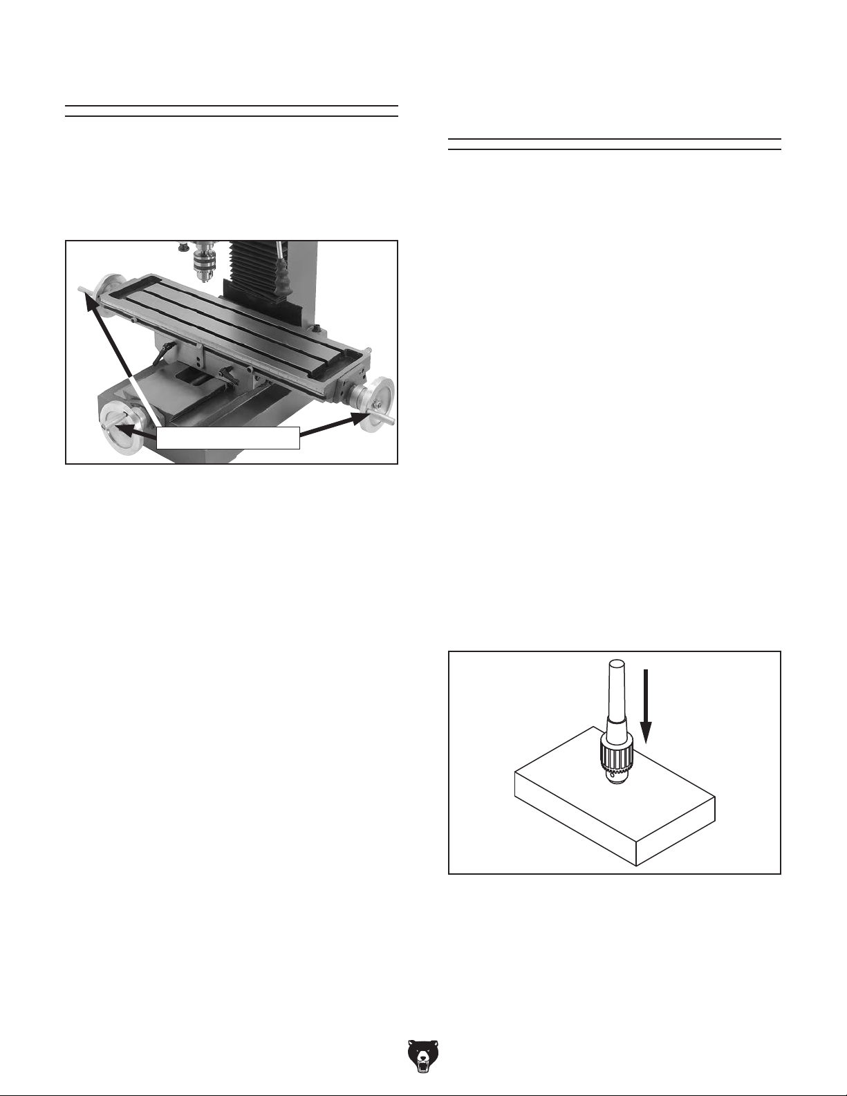
Controlling Table Travel ............................... 23
Installing/Removing Tooling ......................... 24
Setting Spindle Speed ................................. 26
Using Tapping Mode .................................... 27
SECTION 5: ACCESSORIES ......................... 28
SECTION 6: MAINTENANCE ......................... 33
Schedule ...................................................... 33
Cleaning & Protecting .................................. 33
Lubrication ................................................... 34
SECTION 7: SERVICE ................................... 38
Troubleshooting ........................................... 38
Adjusting Gibs .............................................. 40
Adjusting Leadscrew Backlash .................... 40
Tightening Return Spring Tension ............... 41
Tramming Spindle ........................................ 42
SECTION 8: WIRING ...................................... 44
Wiring Safety Instructions ............................ 44
Component Location .................................... 45
Spindle Motor Wiring Diagram ..................... 45
Main Wiring Diagram ................................... 46
Main Wiring Photos ...................................... 47
SECTION 9: PARTS ....................................... 48
Table & Base ............................................... 48
Headstock .................................................... 50
Downfeed Handle ........................................ 53
Column ......................................................... 54
Electrical Parts ............................................. 55
Accessories .................................................. 56
Labels & Cosmetics ..................................... 57
WARRANTY & RETURNS ............................. 61
Page 4
INTRODUCTION
We are proud to provide a high-quality owner’s
manual with your new machine!
We
instructions, specifications, drawings, and photographs
in this manual. Sometimes we make mistakes, but
our policy of continuous improvement also means
that
you receive is
slightly different than shown in the manual
If you find this to be the case, and the difference
between the manual and machine leaves you
confused or unsure about something
check our
website for an updated version. W
current
manuals and
on our web-
site at
Alternatively, you can call our Technical Support
for help. Before calling, make sure you write down
the
from
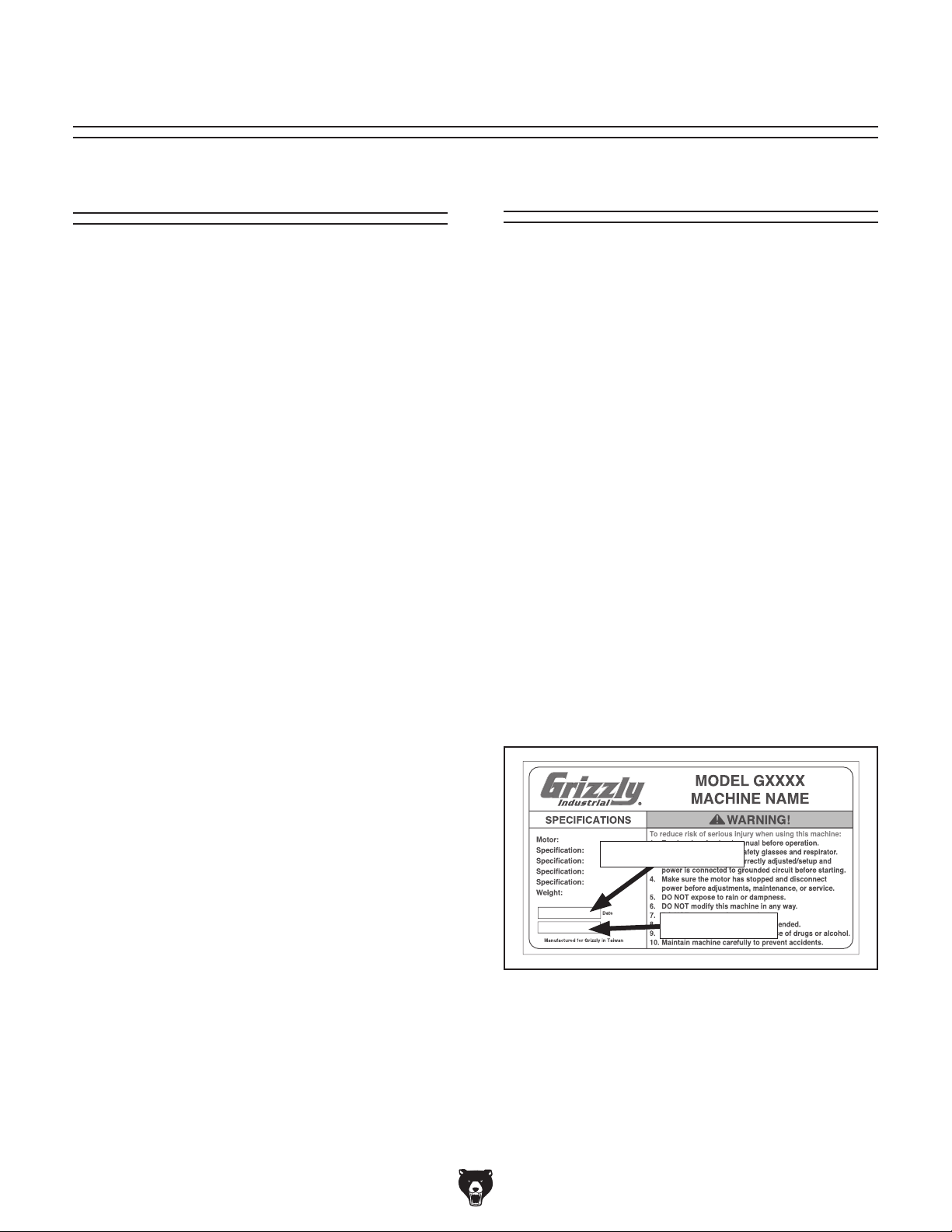
the machine ID label (see below). This information
is required for us to provide proper tech support,
and it helps us determine if updated documentation is available for your machine.
We stand behind our machines. If you have
any questions or need help, use the information
below to contact us. Before contacting, please get
the serial number and manufacture date of your
machine. This will help us help you faster.
We want your feedback on this manual. What did
you like about it? Where could it be improved?
Please take a few minutes to give us feedback.
Email: manuals@grizzly.com
Contact Info
Grizzly Technical Support
1203 Lycoming Mall Circle
Muncy, PA 17756
Phone: (570) 546-9663
Email: techsupport@grizzly.com
Grizzly Documentation Manager
P.O. Box 2069
Bellingham, WA 98227-2069
Manual Accuracy
made every effort to be exact with the
sometimes the machine
.
,
e post
manual updates for free
www.grizzly.com.
Manufacture Date and Serial Number
Manufacture Date
Serial Number
-2-
Model G0795 (Mfd. Since 02/15)
Page 5
Identification
To reduce your risk of
serious injury, read this
entire manual BEFORE
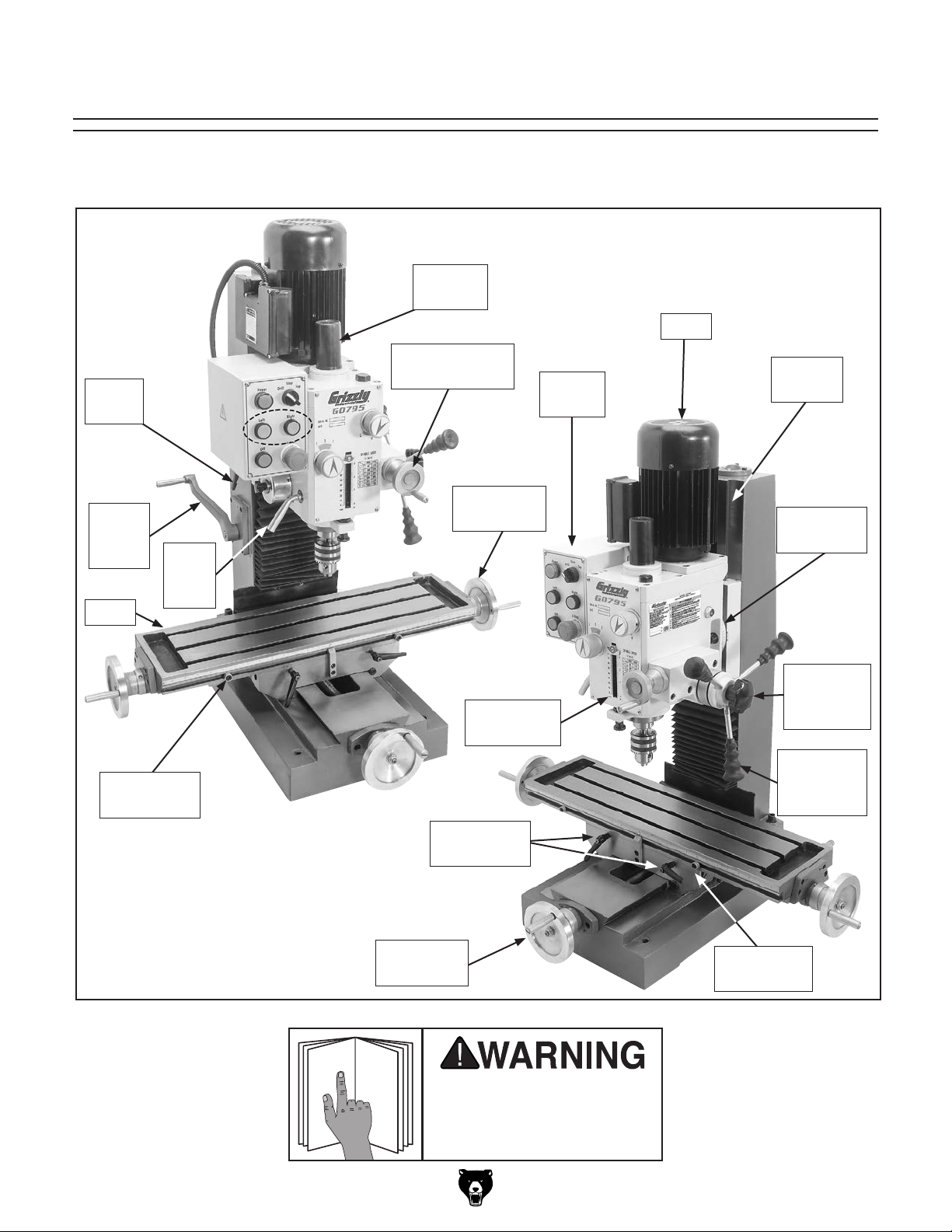
Become familiar with the names and locations of the controls and features shown below to better understand
the instructions in this manual.
Drawbar
Cover
Motor
Z-Axis
Lock
Z-Axis
Hand
Lever
Table
Work Table
Stop
Quill
Lock
Lever
Fine Downfeed
Handwheel
X-Axis
Handwheel
Depth Stop
& Scale
Control
Panel
Dovetail
Column
Headstock
Tilt Scale
Downfeed
Selector
Knob
Coarse
Downfeed
Handle
Model G0795 (Mfd. Since 02/15)
Table Locks
Y-Axis
Handwheel
using machine.
X-Axis
Work Table
Stop
-3-
Page 6
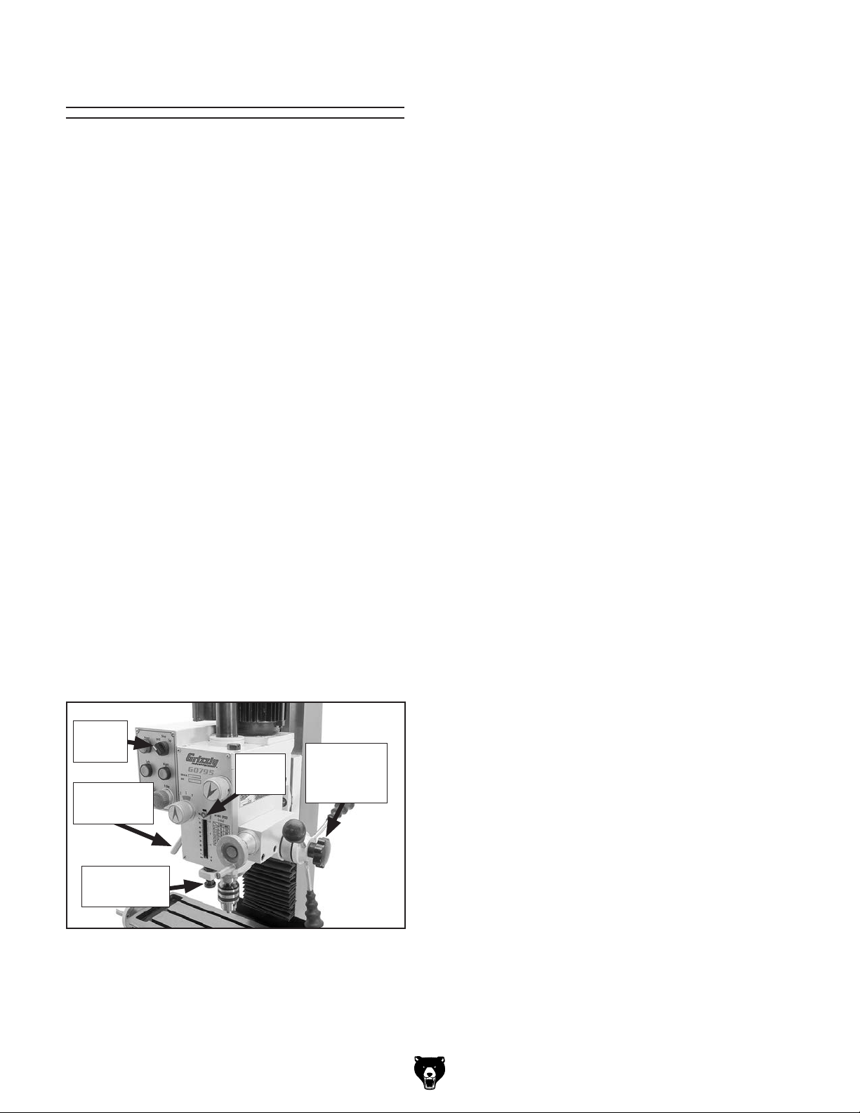
Controls &
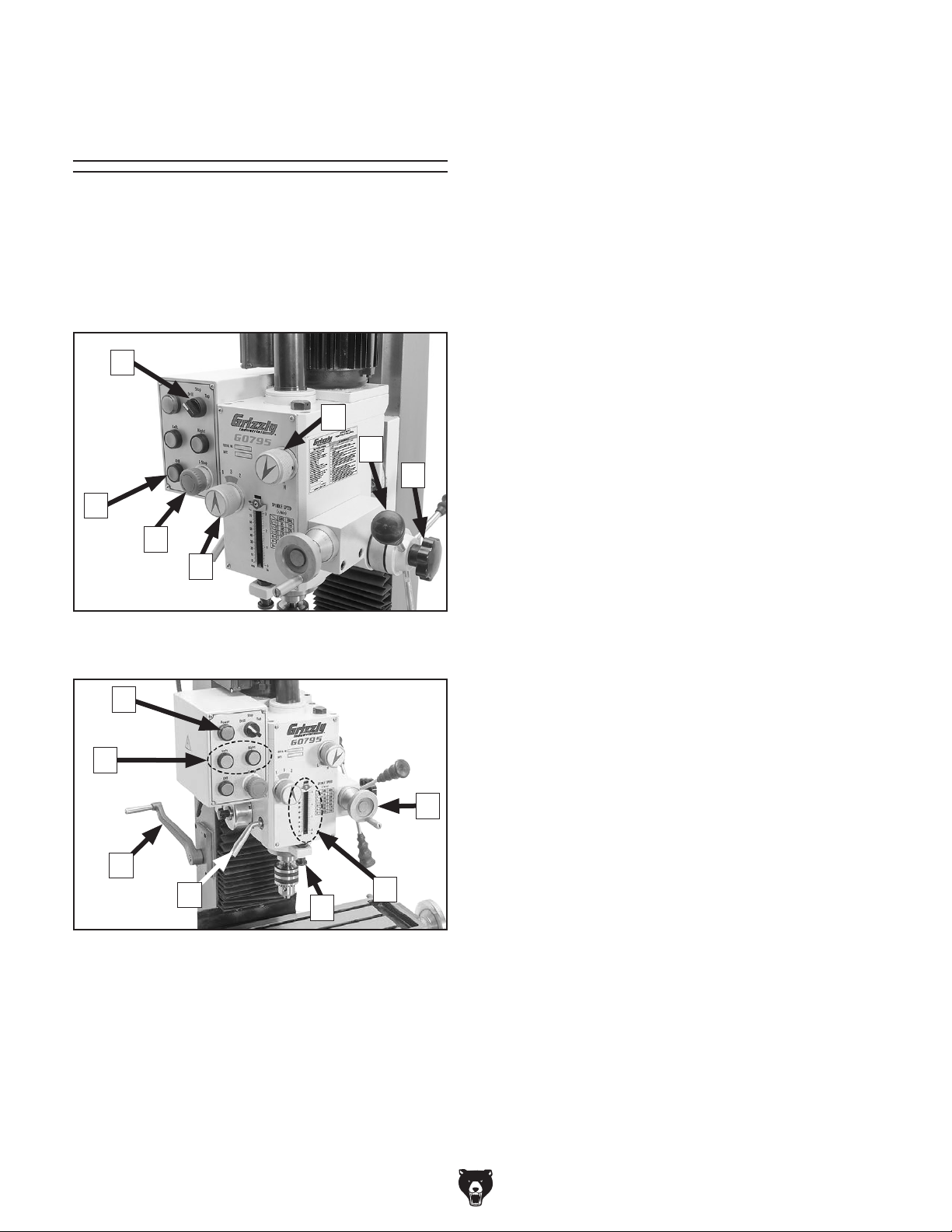
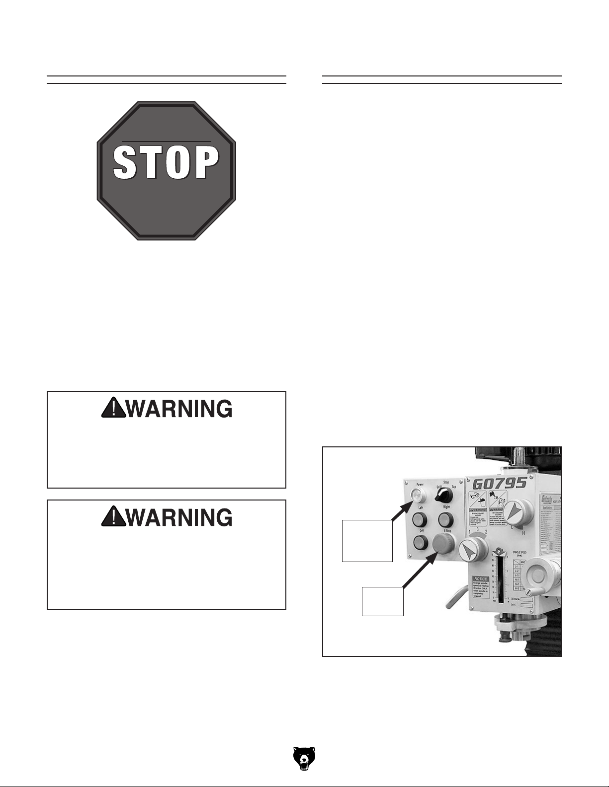
A. Mode Switch: Sets the spindle mode to
either Drill, Stop or Tap.
Components
Refer to Figures 1–2 the following descriptions to
become familiar with the basic controls and components of this machine. Understanding these
items and how they work will help you understand
the rest of the manual and stay safe when operating this machine.
A
B
C
D
G
F
E
B. High/Low Range Knob: Selects either high
or low spindle speed range.
C. Coarse Downfeed Handle: Typically used
for drilling operations for rapid drilling or
plunge cutting. Spring assisted return automatically returns spindle to top position when
released.
D. Downfeed Selector Knob: Selects fine or
coarse downfeed controls. When loosened,
coarse downfeed is engaged; when tightened, fine downfeed is engaged.
E. Spindle Speed Knob: Selects one of three
spindle speeds in the selected speed range.
F. E-Stop Button: Cuts power to the spindle
motor and remains depressed until reset.
Twist clockwise to reset.
G. OFF Button: Stops spindle rotation.
Figure 1. Control panel and spindle speed
controls (right view).
H
N
M
L
K
Figure 2. Control panel and spindle speed
controls (left view).
J
H. POWER Indicator Light: Illuminates when
machine is connected to power.
I. Fine Downfeed Handwheel: Moves spindle
up and down for precise Z-axis control when
milling. Micrometer collar graduated in increments of 0.001".
J. Depth Stop and Scale: Limits depth of
spindle downfeed stroke to preset height as
I
indicated on the scale.
K. Depth Stop Adjustment Knob: Adjusts
position of depth stop.
L. Quill Lock Lever: Locks quill at desired
height above workpiece.
M. Headstock Elevation Crank Handle: Moves
headstock up and down for proper spindle
position during setup.
N. Spindle Direction Buttons: Controls spindle
direction of rotation (as viewed from above).
The spindle must be completely stopped
before either button is pushed.
-4-
Model G0795 (Mfd. Since 02/15)
Page 7

MACHINE DATA
SHEET
Customer Service #: (570) 546-9663 · To Order Call: (800) 523-4777 · Fax #: (800) 438-5901
MODEL G0795 HEAVY DUTY BENCHTOP MILL/DRILL
Product Dimensions:
Weight.............................................................................................................................................................. 408 lbs.
Width (side-to-side) x Depth (front-to-back) x Height............................................................... 39 x 30-1/2 x 49-1/2 in.
Footprint (Length x Width)............................................................................................................................ 22 x 14 in.
Space Required for Full Range of Movement (Width x Depth)........................................................ 52-1/2 x 27-1/2 in.
Shipping Dimensions:
Type.......................................................................................................................................................... Wood Crate
Content........................................................................................................................................................... Machine
Weight.............................................................................................................................................................. 496 lbs.
Length x Width x Height....................................................................................................................... 30 x 29 x 43 in.
Must Ship Upright................................................................................................................................................... Yes
Electrical:
Power Requirement........................................................................................................... 220V, Single-Phase, 60 Hz
Prewired Voltage.................................................................................................................................................. 220V
Full-Load Current Rating....................................................................................................................................... 6.8A
Minimum Circuit Size.............................................................................................................................................. 15A
Connection Type....................................................................................................................................... Cord & Plug
Power Cord Included.............................................................................................................................................. Yes
Power Cord Length................................................................................................................................................. 6 ft.
Power Cord Gauge......................................................................................................................................... 18 AWG
Plug Included.......................................................................................................................................................... Yes
Recommended Plug Type..................................................................................................................................... 6-15
Switch Type............................................................................................ Control Panel w/Magnetic Switch Protection
Motors:
Main
Type................................................................................................................. TEFC Capacitor-Start Induction
Horsepower................................................................................................................................................ 1 HP
Phase............................................................................................................................................ Single-Phase
Amps........................................................................................................................................................... 6.8A
Speed................................................................................................................................................ 1700 RPM
Bearings..................................................................................................... Shielded & Permanently Lubricated
Model G0795 (Mfd. Since 02/15)
-5-
Page 8

Main Specifications:
Operation Info
Spindle Travel.............................................................................................................................................. 3 in.
Max Distance Spindle to Column..........................................................................................................
Max Distance Spindle to Table............................................................................................................ 16-1/8 in.
Longitudinal Table Travel (X-Axis)....................................................................................................
Longitudinal Leadscrew (X-Axis).........................................................................................................
Cross Table Travel (Y-Axis)..................................................................................................................
Cross Leadscrew (Y-Axis)................................................................................................................... 14-3/4 in.
Vertical Leadscrew (Z-Axis)............................................................................................................... 17-3/16 in.
Vertical Head Travel (Z-Axis).............................................................................................................. 13-3/4 in.
Head Tilt (Left/Right).............................................................................................................................. 45 deg.
Drilling Capacity for Cast Iron................................................................................................................ 1-1/4 in.
Drilling Capacity for Steel.................................................................................................................... 1-3/16 in.
Tapping Speed.................................................................................................................................... 115 RPM
End Milling Capacity................................................................................................................................. 5/8 in.
Face Milling Capacity............................................................................................................................ 2-1/2 in.
Table Info
Table Length........................................................................................................................................ 27-1/2 in.
Table Width........................................................................................................................................... 7-1/2 in.
Table Thickness.................................................................................................................................. 1-9/16 in.
Number of T-Slots............................................................................................................................................ 3
T-Slot Size.............................................................................................................................................. 7/16 in.
T-Slots Centers...................................................................................................................................... 2-1/2 in.
X/Y-Axis Travel per Handwheel Revolution.............................................................................................. 0.1 in.
Z-Axis Travel per Handwheel Revolution................................................................................................. 0.1 in.
7-1/2 in.
14-3/16 in.
27-1/2 in.
7-1/2 in.
Spindle Info
Spindle Taper............................................................................................................................................... R-8
Number of Vertical Spindle Speeds.................................................................................................................. 6
Range of Vertical Spindle Speeds........................................................................................... 115 – 1700 RPM
Quill Diameter........................................................................................................................................ 3-1/2 in.
Drawbar Thread Size............................................................................................................................. 7/16-20
Drawbar Length................................................................................................................................. 12-3/16 in.
Spindle Bearings........................................................................................................... Tapered Roller Bearing
Construction
Spindle Housing/Quill................................................................................................................................. Steel
Table.................................................................................................................................................... Cast Iron
Head.................................................................................................................................................... Cast Iron
Column/Base....................................................................................................................................... Cast Iron
Paint Type/Finish.................................................................................................................................... Enamel
Other Specifications:
Country of Origin ................................................................................................................................................ China
Warranty ........................................................................................................................................................... 1 Year
Serial Number Location .................................................................................................................................. ID Label
ISO 9001 Factory .................................................................................................................................................. Yes
Features:
6-Speed gearbox
Drill/tap function
Cast iron construction
Precision-ground dovetail ways and column
Coolant trough built into table
Coarse/fine spindle downfeed w/stops
-6-
Model G0795 (Mfd. Since 02/15)
Page 9

SECTION 1: SAFETY
For Your Own Safety, Read Instruction
Manual Before Operating This Machine
The purpose of safety symbols is to attract your attention to possible hazardous conditions.
This manual uses a series of symbols and signal words intended to convey the level of importance of the safety messages. The progression of symbols is described below. Remember that
safety messages by themselves do not eliminate danger and are not a substitute for proper
accident prevention measures. Always use common sense and good judgment.
Indicates an imminently hazardous situation which, if not avoided,
WILL result in death or serious injury.
Indicates a potentially hazardous situation which, if not avoided,
COULD result in death or serious injury.
Indicates a potentially hazardous situation which, if not avoided,
MAY result in minor or moderate injury. It may also be used to alert
against unsafe practices.
This symbol is used to alert the user to useful information about
NOTICE
proper operation of the machine.
Safety Instructions for Machinery
OWNER’S MANUAL. Read and understand this
owner’s manual BEFORE using machine.
TRAINED OPERATORS ONLY. Untrained operators have a higher risk of being hurt or killed.
Only allow trained/supervised people to use this
machine. When machine is not being used, disconnect power, remove switch keys, or lock-out
machine to prevent unauthorized use—especially
around children. Make workshop kid proof!
DANGEROUS ENVIRONMENTS. Do not use
machinery in areas that are wet, cluttered, or have
poor lighting. Operating machinery in these areas
greatly increases the risk of accidents and injury.
MENTAL ALERTNESS REQUIRED. Full mental
alertness is required for safe operation of machinery. Never operate under the influence of drugs or
alcohol, when tired, or when distracted.
ELECTRICAL EQUIPMENT INJURY RISKS. You
can be shocked, burned, or killed by touching live
electrical components or improperly grounded
machinery. To reduce this risk, only allow qualified
service personnel to do electrical installation or
repair work, and always disconnect power before
accessing or exposing electrical equipment.
DISCONNECT POWER FIRST.
nect machine from power supply BEFORE making
adjustments, changing tooling, or servicing machine.
This prevents an injury risk from unintended startup
or contact with live electrical components.
EYE PROTECTION. Always wear ANSI-approved
safety glasses or a face shield when operating or
observing machinery to reduce the risk of eye
injury or blindness from flying particles. Everyday
eyeglasses are NOT approved safety glasses.
Always discon-
Model G0795 (Mfd. Since 02/15)
-7-
Page 10

WEARING PROPER APPAREL. Do not wear
clothing, apparel or jewelry that can become
entangled in moving parts. Always tie back or
cover long hair. Wear non-slip footwear to reduce
risk of slipping and losing control or accidentally
contacting cutting tool or moving parts.
HAZARDOUS DUST. Dust created by machinery
operations may cause cancer, birth defects, or
long-term respiratory damage. Be aware of dust
hazards associated with each workpiece material. Always wear a NIOSH-approved respirator to
reduce your risk.
HEARING PROTECTION. Always wear hearing protection when operating or observing loud
machinery. Extended exposure to this noise
without hearing protection can cause permanent
hearing loss.
REMOVE ADJUSTING TOOLS. Tools left on
machinery can become dangerous projectiles
upon startup. Never leave chuck keys, wrenches,
or any other tools on machine. Always verify
removal before starting!
USE CORRECT TOOL FOR THE JOB. Only use
this tool for its intended purpose—do not force
it or an attachment to do a job for which it was
not designed. Never make unapproved modifications—modifying tool or using it differently than
intended may result in malfunction or mechanical
failure that can lead to personal injury or death!
AWKWARD POSITIONS. Keep proper footing
and balance at all times when operating machine.
Do not overreach! Avoid awkward hand positions
that make workpiece control difficult or increase
the risk of accidental injury.
CHILDREN & BYSTANDERS. Keep children and
bystanders at a safe distance from the work area.
Stop using machine if they become a distraction.
GUARDS & COVERS. Guards and covers reduce
accidental contact with moving parts or flying
debris. Make sure they are properly installed,
undamaged, and working correctly BEFORE
operating machine.
FORCING MACHINERY. Do not force machine.
It will do the job safer and better at the rate for
which it was designed.
NEVER STAND ON MACHINE. Serious injury
may occur if machine is tipped or if the cutting
tool is unintentionally contacted.
STABLE MACHINE. Unexpected movement during operation greatly increases risk of injury or
loss of control. Before starting, verify machine is
stable and mobile base (if used) is locked.
USE RECOMMENDED ACCESSORIES. Consult
this owner’s manual or the manufacturer for recommended accessories. Using improper accessories will increase the risk of serious injury.
UNATTENDED OPERATION. To reduce the
risk of accidental injury, turn machine OFF and
ensure all moving parts completely stop before
walking away. Never leave machine running
while unattended.
MAINTAIN WITH CARE. Follow all maintenance
instructions and lubrication schedules to keep
machine in good working condition. A machine
that is improperly maintained could malfunction,
leading to serious personal injury or death.
DAMAGED PARTS. Regularly inspect machine
for damaged, loose, or mis-adjusted parts—or
any condition that could affect safe operation.
Immediately repair/replace BEFORE operating
machine. For your own safety, DO NOT operate
machine with damaged parts!
MAINTAIN POWER CORDS. When disconnecting cord-connected machines from power, grab
and pull the plug—NOT the cord. Pulling the cord
may damage the wires inside. Do not handle
cord/plug with wet hands. Avoid cord damage by
keeping it away from heated surfaces, high traffic
areas, harsh chemicals, and wet/damp locations.
EXPERIENCING DIFFICULTIES. If at any time
you experience difficulties performing the intended operation, stop using the machine! Contact our
Technical Support at (570) 546-9663.
-8-
Model G0795 (Mfd. Since 02/15)
Page 11

Additional Safety for Mill/Drills
The primary risks of operating a mill are as follows: You can be seriously injured or killed by
getting clothing, jewelry, or long hair entangled with rotating cutter. You can be severely cut
or have fingers amputated from contact with the rotating cutter. You can be blinded or struck
by broken cutting tools, metal chips, workpieces, or adjustment tools thrown from the rotating
spindle with great force. To reduce your risk of serious injury when operating this machine,
completely heed and understand the following:
UNDERSTAND ALL CONTROLS. Make sure you
understand the function and proper use of all controls before starting. This will help you avoid making mistakes that result in serious injury.
WEAR FACE SHIELD. Always wear a face shield
in addition to safety glasses. This provides more
complete protection for your face than safety
glasses alone.
REMOVE CHUCK KEY & SPINDLE TOOLS.
Always remove chuck key, drawbar wrench, and
other tools used on the spindle immediately after
use. This will prevent them from being thrown by
the spindle upon startup.
PROPERLY SECURE CUTTER. Firmly secure
cutting tool or drill bit so it does not fly out of spindle during operation.
USE CORRECT SPINDLE SPEED. Follow recommended speeds and feeds for each size and
type of cutting tool. This helps avoid tool breakage
during operation and ensures best cutting results.
INSPECT CUTTING TOOL. Inspect cutting tools
for sharpness, chips, or cracks before each use.
Replace dull, chipped, or cracked cutting tools
immediately.
ALLOW SPINDLE TO STOP. To minimize your
risk of entanglement, always allow spindle to stop
on its own. DO NOT stop spindle using your hand
or any other object.
PROPERLY SECURE WORKPIECE. Clamp
workpiece to table or secure in a vise mounted to
table, so workpiece cannot unexpectedly shift or
spin during operation. NEVER hold workpiece by
hand during operation.
CLEAN MACHINE SAFELY. Metal chips or shavings can be razor sharp. DO NOT clear chips
by hand or compressed air that can force chips
farther into machine—use a brush or vacuum
instead. Never clear chips while spindle is turning.
PROPERLY MAINTAIN MACHINE. Keep machine
in proper working condition to help ensure that it
functions safely and all guards and other components work as intended. Perform routine inspections and all necessary maintenance. Never operate machine with damaged or worn parts that can
break or result in unexpected movement during
operation.
DISCONNECT POWER FIRST. To reduce risk of
electrocution or injury from unexpected startup,
make sure mill/drill is turned OFF, disconnected
from power, and all moving parts have come to
a complete stop before changing cutting tools or
starting any inspection, adjustment, or maintenance procedure.
POWER DISRUPTION. In the event of a local
power outage during operation, turn spindle switch
OFF to avoid a possible sudden startup once
power is restored.
Like all machinery there is potential danger when operating this machine. Accidents are frequently caused by lack of familiarity or failure to pay attention. Use this machine with respect
and caution to lessen the possibility of operator injury. If normal safety precautions are overlooked or ignored, serious personal injury may occur.
Model G0795 (Mfd. Since 02/15)
-9-
Page 12

SECTION 2: POWER SUPPLY
Before installing the machine, consider the availability and proximity of the required power supply
circuit. If an existing circuit does not meet the
requirements for this machine, a new circuit must
be installed. To minimize the risk of electrocution,
fire, or equipment damage, installation work and
electrical wiring must be done by an electrician or
qualified service personnel in accordance with all
applicable codes and standards.
Electrocution, fire, or
equipment damage may
occur if machine is not
correctly grounded and
connected to the power
The full-load current rating is the amperage a
machine draws at 100% of the rated output power.
On machines with multiple motors, this is the
amperage drawn by the largest motor or sum of all
motors and electrical devices that might operate
at one time during normal operations.
The full-load current is not the maximum amount
of amps that the machine will draw. If the machine
is overloaded, it will draw additional amps beyond
the full-load rating.
If the machine is overloaded for a sufficient length
of time, damage, overheating, or fire may result—
especially if connected to an undersized circuit.
To reduce the risk of these hazards, avoid overloading the machine during operation and make
sure it is connected to a power supply circuit that
meets the requirements in the following section.
This machine is prewired to operate on a 220V
power supply circuit that has a verified ground and
meets the following requirements:
For your own safety and protection of
Note: The circuit requirements listed in this manual apply to a dedicated circuit—where only one
machine will be running at a time. If this machine
will be connected to a shared circuit where multiple machines will be running at the same time,
consult a qualified electrician to ensure that the
circuit is properly sized for safe operation.
A power supply circuit includes all electrical
equipment between the breaker box or fuse panel
in the building and the machine. The power supply circuit used for this machine must be sized to
safely handle the full-load current drawn from the
machine for an extended period of time. (If this
machine is connected to a circuit protected by
fuses, use a time delay fuse marked D.)
Availability
supply.
Full-Load Current Rating
Circuit Requirements for 220V
Nominal Voltage ........................................220V
Cycle .......................................................... 60 Hz
Phase ........................................... Single-Phase
Power Supply Circuit ......................... 15 Amps
Plug/Receptacle ......................................... 6-15
property, consult an electrician if you are
unsure about wiring practices or electrical
codes in your area.
Full-Load Current Rating at 220V .... 6.8 Amps
-10 -
Model G0795 (Mfd. Since 02/15)
Page 13
Grounding Instructions
This machine MUST be grounded. In the event
of certain malfunctions or breakdowns, grounding
reduces the risk of electric shock by providing a
path of least resistance for electric current.
We do not recommend using an extension cord
with this machine.
cord, only use it if absolutely necessary and only
on a temporary basis.
Extension cords cause voltage drop, which may
damage electrical components and shorten motor
life. Voltage drop increases as the extension cord
size gets longer and the gauge size gets smaller
(higher gauge numbers indicate smaller sizes).
Any extension cord used with this machine must
contain a ground wire, match the required plug
and receptacle, and meet the following requirements:
Improper connection of the equipment-grounding
wire can result in a risk of electric shock. The
wire with green insulation (with or without yellow
stripes) is the equipment-grounding wire. If repair
or replacement of the power cord or plug is necessary, do not connect the equipment-grounding
wire to a live (current carrying) terminal.
Check with a qualified electrician or service personnel if you do not understand these grounding
requirements, or if you are in doubt about whether
the tool is properly grounded. If you ever notice
that a cord or plug is damaged or worn, disconnect it from power, and immediately replace it with
a new one.
Serious injury could occur if you connect
process. DO NOT connect to power until
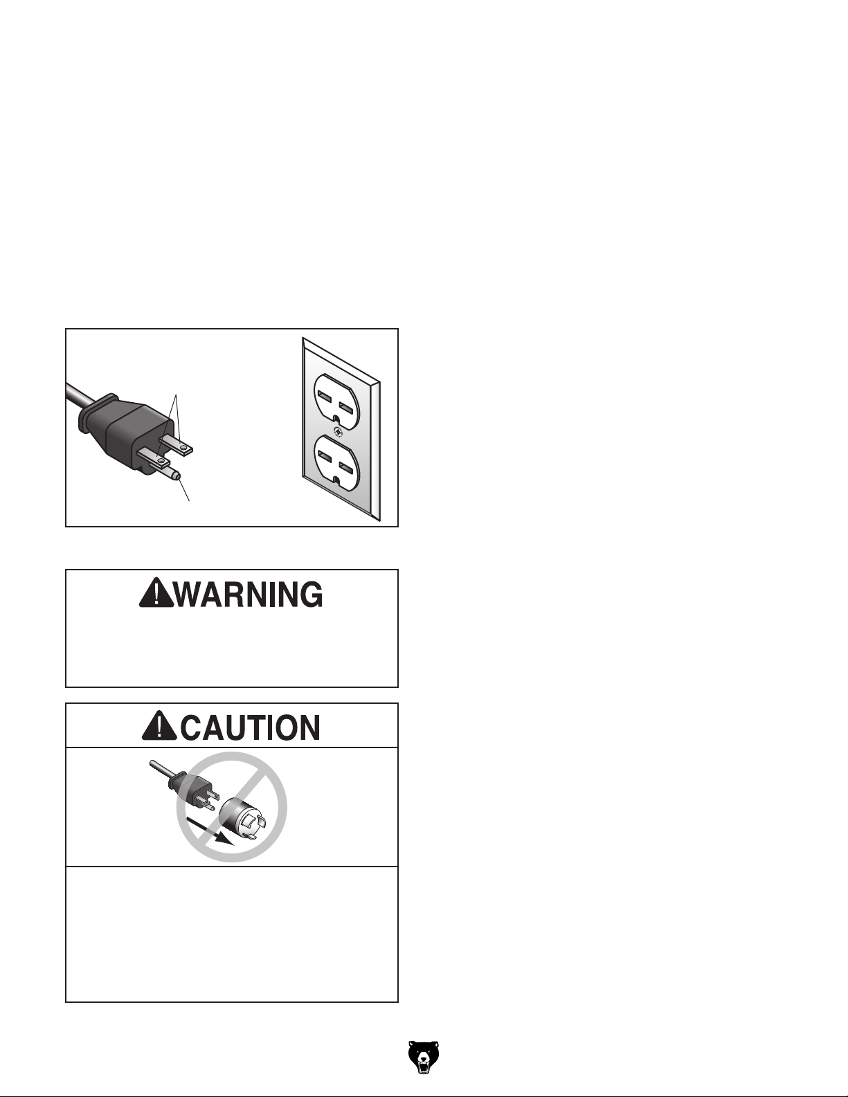
The power cord and plug specified under “Circuit
Requirements for 220V”
has an equipment-grounding wire and a grounding prong. The plug must only be inserted into
a matching receptacle (outlet) that is properly
installed and grounded in accordance with all
local codes and ordinances (see figure below).
No adapter should be used with the
required plug. If the plug does not fit the
available receptacle, or the machine must
on the previous page
GROUNDED
6-15 RECEPTACLE
Current Carrying Prongs
6-15 PLUG
Extension Cords
If you must use an extension
Grounding Prong
Figure 3. Typical 6-15 plug and receptacle.
machine to power before completing setup
instructed later in this manual.
be reconnected for use on a different type
of circuit, the reconnection must be made
by a qualified electrician and comply with all
local codes and ordinances.
Model G0795 (Mfd. Since 02/15)
Minimum Gauge Size ...........................14 AWG
Maximum Length (Shorter is Better).......50 ft.
-11-
Page 14
SECTION 3: SETUP
Your machine was carefully packaged for safe
transportation. Remove the packaging materials
from around your machine and inspect it. If you
discover any damage, please call us immediately
at (570) 546-9663
Save the containers and all packing materials for
possible inspection by the carrier or its agent.
Otherwise, filing a freight claim can be difficult.
When you are completely satisfied with the condi
tion of your shipment, inventory the contents.
The following is a list of items shipped with your
machine. Before beginning setup, lay these items
out and inventory them.
If any non-proprietary parts are missing (e.g. a
nut or a washer), we will gladly replace them; or
for the sake of expediency, replacements can be
obtained at your local hardware store.
To reduce your risk of
serious injury, read this
entire manual BEFORE
Unpacking Inventory
for advice.
Needed for Setup
The following items are needed, but not included,
for the setup/assembly of this machine.
Description Qty
• Additional People ....................................... 1
• Safety Glasses ........................................... 1
• Cleaner/Degreaser (Page 13) .... As Needed
• Disposable Shop Rags ............... As Needed
• Forklift ......................................................... 1
• Lifting Sling (rated for at least 1000 lbs.) .... 1
• Mounting Hardware (Page 15) ... As Needed
• Brass Hammer (Page 16) .......................... 1
• Mineral Spirits (Page 16) ............ As Needed
• Wood Block (Page 16) ............................... 1
-
If you cannot find an item on this list, carefully check around/inside the machine and
packaging materials. Often, these items get
lost in packaging materials while unpacking or they are pre-installed at the factory.
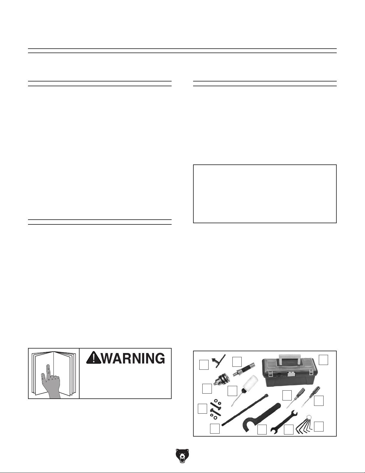
Small Item Inventory (Figure 4) Qty
A. Drawbar
B. T-Bolt M10-1.5 x 60 w/Washer and Nuts .... 2
C. Drill Chuck B16, 3-16mm ............................ 1
D. Drill Chuck Key. .......................................... 1
E. Spindle Sleeve R-8 .................................... 1
F. Bottle for Oil ............................................... 1
G. Toolbox ....................................................... 1
H. Phillips Head Screwdriver #2 ..................... 1
I. Flat Head Screwdriver #2 ........................... 1
J. Hex Wrenches 2.5, 3, 4, 5, 6mm .........1 Ea.
K. Open-End Wrench 17/19mm ...................... 1
L. Spindle Wrench .......................................... 1
M. Handwheel Handle Assembly (not shown) . . 2
NOTICE
7
⁄16"–20" x 31⁄2 " .............................. 1
-12-
using machine.
D
C
B
A
E
F
Figure 4. Toolbox inventory.
Model G0795 (Mfd. Since 02/15)
H
KL
G
I
J
Page 15
The unpainted surfaces of your machine are
coated with a heavy-duty rust preventative that
prevents corrosion during shipment and storage.
This rust preventative works extremely well, but it
will take a little time to clean.
Be patient and do a thorough job cleaning your
machine. The time you spend doing this now will
give you a better appreciation for the proper care
of your machine's unpainted surfaces.
There are many ways to remove this rust preventative, but the following steps work well in a wide
variety of situations. Always follow the manufacturer’s instructions with any cleaning product you
use and make sure you work in a well-ventilated
area to minimize exposure to toxic fumes.
Before cleaning, gather the following:
• Disposable rags
• Cleaner/degreaser (WD•40 works well)
• Safety glasses & disposable gloves
• Plastic paint scraper (optional)
Basic steps for removing rust preventative:
1.
2.
3.
4.
Many cleaning solvents
work in a well-ventilated
Avoid chlorine-based solvents, such as
Cleanup
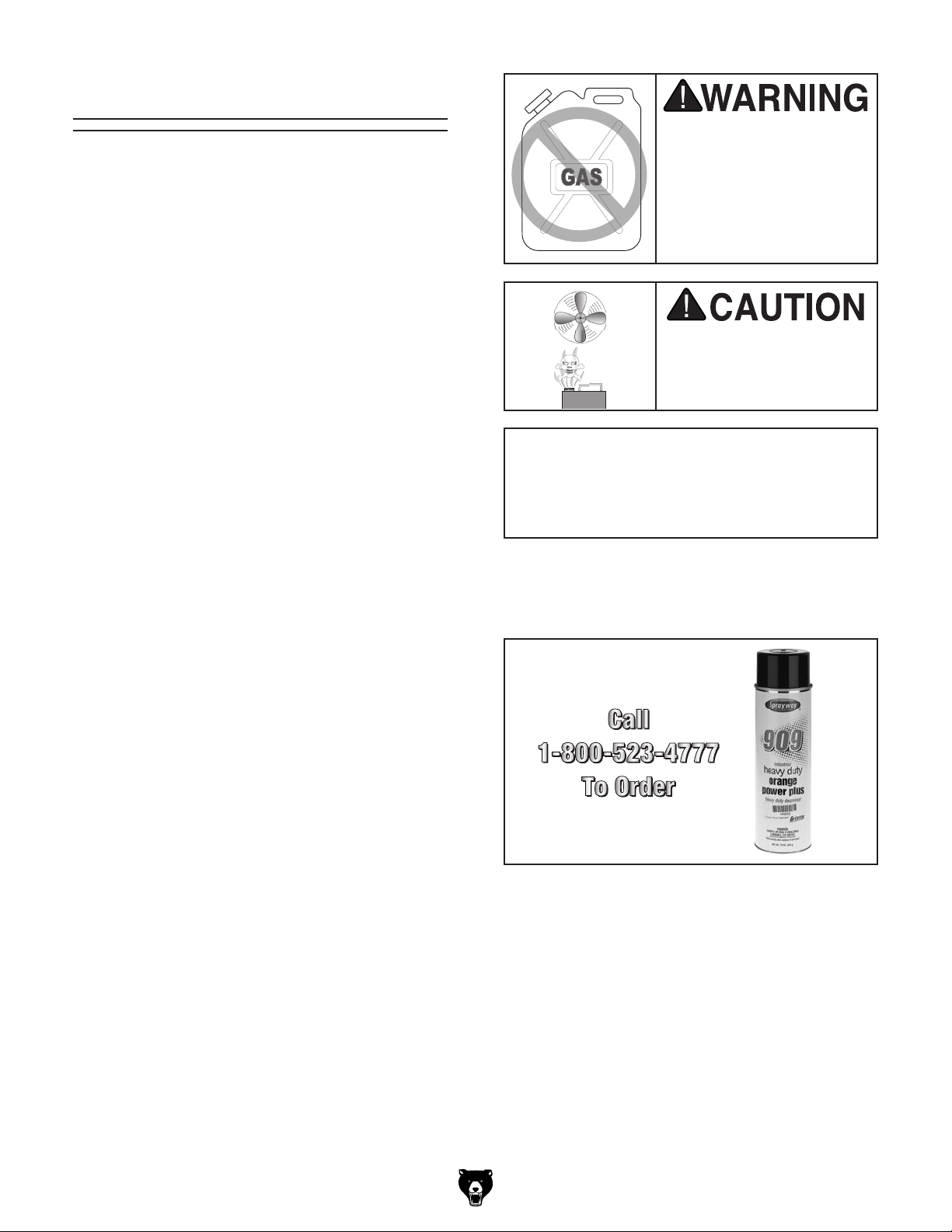
Gasoline and petroleum
products have low flash
points and can explode
or cause fire if used to
clean machinery. Av o id
using these products
to clean machinery.
Put on safety glasses.
Coat the rust preventative with a liberal
amount of cleaner/degreaser, then let it soak
for 5–10 minutes.
Wipe off the surfaces. If your cleaner/degreas-
er is effective, the rust preventative will wipe
off easily. If you have a plastic paint scraper,
scrape off as much as you can first, then wipe
off the rest with the rag.
are toxic if inhaled. Only
area.
NOTICE
acetone or brake parts cleaner, that may
damage painted surfaces.
T23692—Orange Power Degreaser
A great product for removing the waxy shipping
grease from your machine during clean up.
Figure 5. T23692 Orange Power Degreaser.
Repeat Steps 2–3 as necessary until clean,
then coat all unpainted surfaces with a quality
metal protectant to prevent rust.
Model G0795 (Mfd. Since 02/15)
-13-
Page 16
Site Considerations
Weight Load
Physical Environment
Place this machine near an existing power source.
Shadows, glare, or strobe effects that may distract
Refer to the Machine Data Sheet for the weight
of your machine. Make sure that the surface upon
which the machine is placed will bear the weight
of the machine, additional equipment that may be
installed on the machine, and the heaviest workpiece that will be used. Additionally, consider the
weight of the operator and any dynamic loading
that may occur when operating the machine.
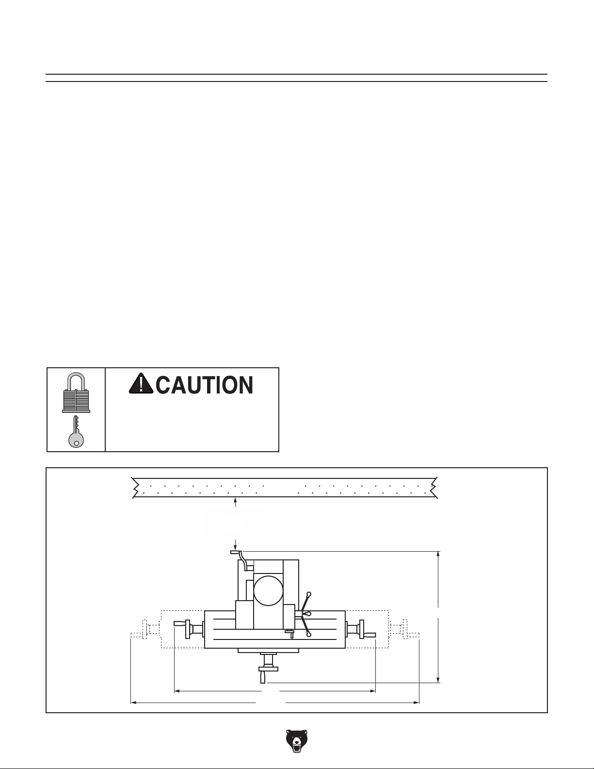
Space Allocation
Consider the largest size of workpiece that will
be processed through this machine and provide
enough space around the machine for adequate
operator material handling or the installation of
auxiliary equipment. With permanent installations,
leave enough space around the machine to open
or remove doors/covers as required by the maintenance and service described in this manual.
See below for required space allocation.
Children or untrained people
may be seriously injured by
this machine. Only install in an
access restricted location.
The physical environment where the machine is
operated is important for safe operation and longevity of machine components. For best results,
operate this machine in a dry environment that is
free from excessive moisture, hazardous chemicals, airborne abrasives, or extreme conditions.
Extreme conditions for this type of machinery are
generally those where the ambient temperature
range exceeds 41°–104°F; the relative humidity
range exceeds 20–95% (non-condensing); or the
environment is subject to vibration, shocks, or
bumps.
Electrical Installation
Make sure all power cords are protected from
traffic, material handling, moisture, chemicals,
or other hazards. Make sure to leave access to
a means of disconnecting the power source or
engaging a lockout/tagout device, if required.
Lighting
Lighting around the machine must be adequate
enough that operations can be performed safely.
or impede the operator must be eliminated.
-14-
Wall
Minimum
30"
For Maintenance
39"
521/2"
Figure 6. Minimum working clearances.
1
27
/2"
Model G0795 (Mfd. Since 02/15)
Page 17
Lifting & Placing
Another option is a "Direct Mount" (see example
below) where the machine is secured directly to
the workbench with lag screws and washers.
The base of this machine has mounting holes
that allow it to be fastened to a workbench or
other mounting surface to prevent it from moving
during operation and causing accidental injury or
damage.
The strongest mounting option is a "Through
Mount" (see example below) where holes are
drilled all the way through the workbench—and
hex bolts, washers, and hex nuts are used to
secure the machine in place.
Bench Mounting
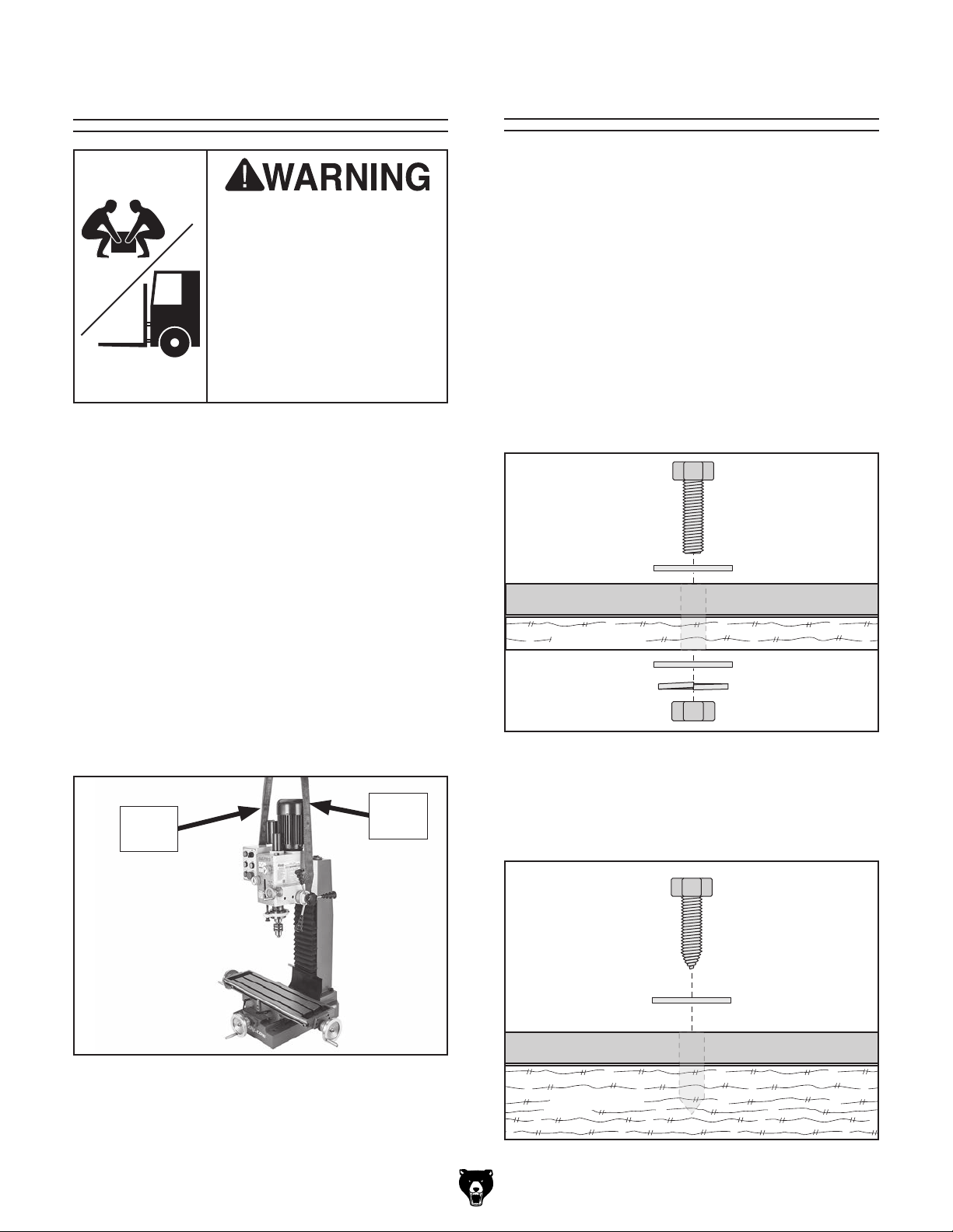
HEAVY LIFT!
Straining or crushing injury
may occur from improperly
lifting machine or some of
its parts. To reduce this
risk, get help from other
people and use a forklift
(or other lifting equipment)
rated for weight of this
machine.
To lift and place machine into position:
1. Move shipping crate next to workbench or
stand, then unbolt machine from pallet.
2. Move machine work table as close to column
as possible, and raise headstock to its highest position. This will help balance machine
when moving.
Number of Mounting Holes ............................ 4
Diameter of Mounting Hardware .................
Hex
Bolt
Flat Washer
Machine Base
1
⁄2"
3. Tighten Z-Axis and table locks (see Page 3)
to avoid sudden shifts when lifting.
4. Position a lifting sling under headstock, as
shown in Figure 7. Connect sling ends to a
forklift, then place machine on workbench.
Lifting
Sling
Figure 7. Recommended lifting sling position
around headstock.
Workbench
Flat Washer
Lock Washer
Hex Nut
Figure 8. Example of a "Through Mount" setup.
Lifting
Sling
Lag Screw
Flat Washer
Machine Base
Workbench
5. Secure machine to workbench following
instructions in Bench Mounting.
Model G0795 (Mfd. Since 02/15)
Figure 9. Example of a "Direct Mount" setup.
-15-
Page 18
Assembly
An arbor is included for the drill chuck that
comes with this machine. The following procedure
describes how to install the arbor in the chuck.
After the arbor is installed in the drill chuck, it
is very difficult to separate the assembly. If you
would like to use a different chuck in the future,
we recommend obtaining a new arbor.
Important: DO NOT install the drill chuck and
arbor assembly into the spindle until AFTER the
test run.
To join drill chuck and arbor:
1.
clean drill
2.
3.
4.
illustrated below.
5. Attempt to separate drill chuck and arbor by
hand —if they separate, repeat Steps 3–4.
The mill/drill was fully assembled at the factory
except for the handwheel handles.
Use a flathead screwdriver to attach the
handwheels handles, as shown in Figure 10.
Joining Drill Chuck
& Arbor
Handwheel Handles
Figure 10. Handwheel handles attached.
Use acetone or lacquer thinner to
chuck and arbor mating surfaces, especially
the bore.
Retract chuck jaws completely into chuck.
Insert small end of arbor into chuck.
Hold assembly by the arbor and tap chuck
onto a block of wood with medium force, as
-16 -
Figure 11. Tapping drill chuck/arbor on block of
wood.
Model G0795 (Mfd. Since 02/15)
Page 19
Lubricating Mill/Drill Test Run
Once assembly is complete, test run the machine
to ensure it is properly connected to power and
safety components are functioning properly.
If you find an unusual problem during the test run,
immediately stop the machine, disconnect it from
power, and fix the problem BEFORE operating the
machine again. The
table in the
SERVICE section of this manual can help.
DO NOT start machine until all preceding
setup instructions have been performed.
Operating an improperly set up machine
ed results that can lead to serious injury,
Serious injury or death can result from
HEADSTOC K MUST
BE FILLED WITH OIL!
OIL MAY NOT BE
SHIPPED WITH MACHINE!
Refer to Lubrication Section
for Correct Oil Type.
The headstock oil reservoir must have the proper
amount of oil in it before the mill/drill can be operated for the first time.
Damage caused by running the mill/drill without
oil in the reservoir will not be covered under warranty. Refer to the Lubrication subsection, beginning on Page 34, for details on how to check and
add oil.
using this machine BEFORE understanding
its controls and related safety information.
DO NOT operate, or allow others to operate,
machine until the information is understood.
Troubleshooting
The test run consists of the following: 1) the motor
powers up and runs correctly, 2) the E-Stop button
safety feature works correctly, and 3) the tapping
controls work correctly.
To test run mill /drill:
1. Clear all setup tools away from machine.
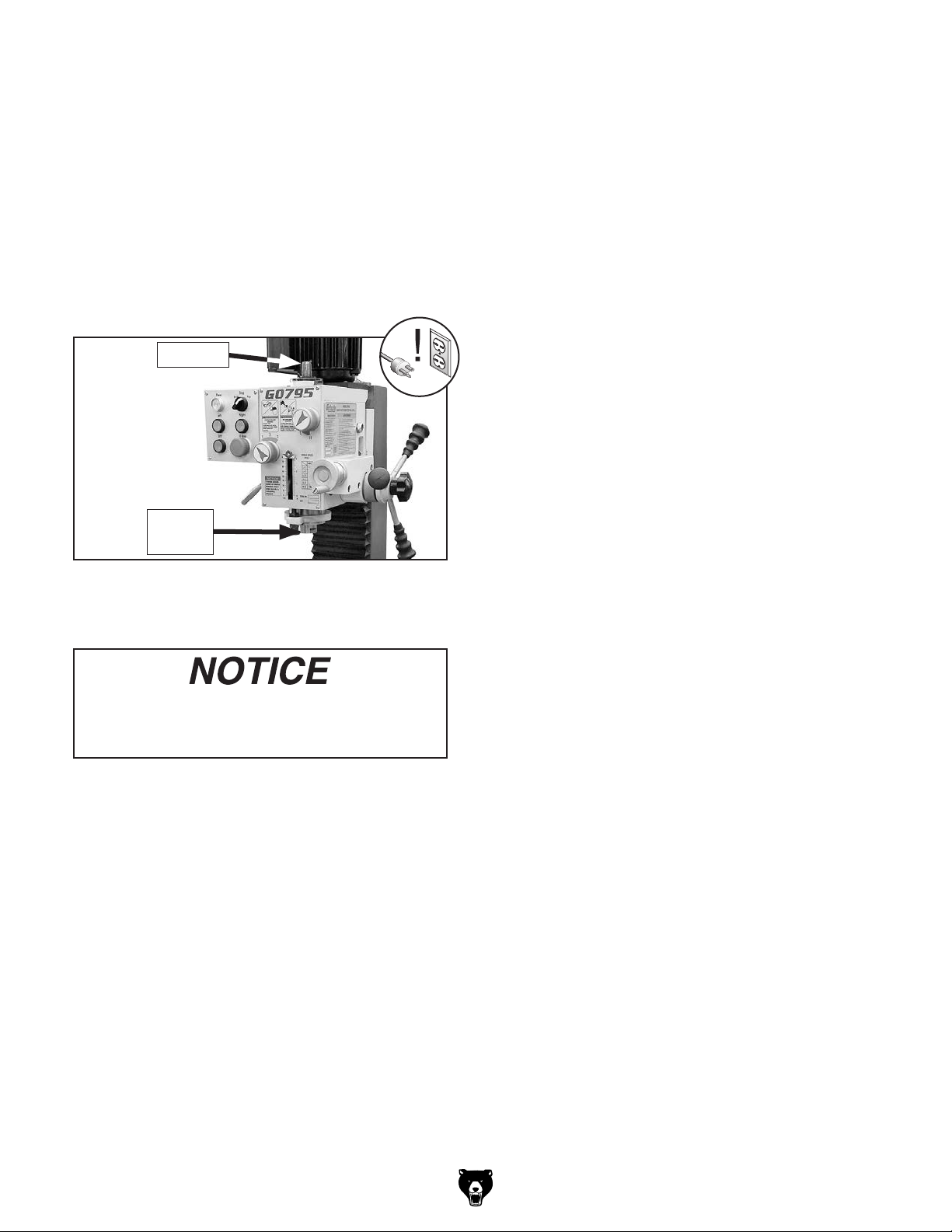
2. Press E-Stop button (see Figure 12). This
will help prevent unexpected startup when
machine is connected to power.
3. Connect machine to power supply, and press
Power button (see Figure 12). Power indicator light should turn ON.
may result in malfunction or unexpect-
death, or machine/property damage.
Model G0795 (Mfd. Since 02/15)
Power
Indicator
Light
E-Stop
Button
Figure 12. Location of power indicator light and
E-Stop button.
4. Rotate mode switch to "Drill".
-17-
Page 20

5. Turn high/low range knob to “L” and spindle
speed knob to “2” (see Figure 13). This
selects a spindle speed of 220 RPM (refer to
spindle speed chart on headstock).
Note: When switching between gears, it may
be necessary to rotate spindle by hand so
gears will align and engage.
6. Twist E-stop button clockwise until it pops out
(see Figure 13)—this resets the button and
enables power to control panel and motor.
11. Without resetting E-Stop button, press "Left"
button. Machine should not start.
—If machine does start (with E-Stop button
pushed in), immediately disconnect power
to machine. E-Stop safety feature is not
working correctly. This safety feature must
work properly before proceeding with regular operations. Refer to Troubleshooting
on Page 38 for help.
12. Twist E-Stop button clockwise to reset it.
Mode
Switch
Spindle
Direction
Buttons
Off
Button
E-Stop
Button
Figure 13. Location of control panel and spindle
speed controls.
7. Press "Left" button (see Figure 13). Spindle
should rotate clockwise (as viewed from top)
and machine should run smoothly with little to
no vibration or rubbing noises.
8. Press "Off" button and wait for spindle to
completely stop.
9. Press "Right" button. Spindle should rotate
counterclockwise (as viewed from top).
High/Low
Range Knob
Spindle
Speed Knob
13. Loosen downfeed selector knob slightly, to
engage coarse downfeed lever.
14. Rotate mode switch to "Tap."
15. Press "Left" button. Spindle should rotate
clockwise.
Note: Spindle will not engage if "Right" but-
ton is pressed while in Tap mode.
16. Use coarse downfeed lever to move spindle
down. Spindle should rotate clockwise.
17. Continue to move spindle down until it reaches bottom of depth stop—spindle should
momentarily stop, then rotate counterclockwise.
18. Use coarse downfeed lever to move spindle
all the way up.
Congratulations! The Test Run is complete.
Continue to the next subsection, Spindle Bearing
Break-In.
10. Press E-stop button and wait for spindle to
completely stop.
-18-
Model G0795 (Mfd. Since 02/15)
Page 21

Spindle Bearing
The spindle break-in procedure distributes lubrication
reduce the risk
of early
if there are any "dry" spots
or areas where lubrication has settled in the bearings. You
efore
placing
for the
first time when the machine is new or if it has
been sitting idle for longer than 6 months.
Always start the spindle break-in at the lowest
speed to minimize wear if there
Allow the spindle to run long enough to warm up
and distribute the bearing grease, then incrementally increase spindle speeds and repeat this process at each speed until reaching the maximum
spindle speed. Following the break-in procedure
in this progressive manner helps minimize any
potential wear that could occur before lubrication
is fully distributed.
You must complete this procedure to maintain the warranty. Failure to do this could
cause rapid wear-and-tear of spindle bearings once they are placed under load.
Break-In
throughout the bearings to
bearing failure
3. Stop spindle. Select the next highest speed
and run spindle for a minimum of 5 minutes
in each direction of rotation.
4. Repeat Step 3 for each remaining speed,
working from lowest to highest. The Spindle
Bearing Break-In is now complete!
must complete this procedure b
operational loads on the spindle
are dry spots.
Inspections &
Adjustments
The following adjustments were performed at the
factory before the machine was shipped:
• Gib Adjustments ............................. Page 40
• Leadscrew Backlash ...................... Page 40
• Return Spring Tension .....................Page 41
Please be aware that these adjustments can
change during the shipping process. Pay careful
attention to these adjustments when first operating the machine. If you find that adjustments are
not set to your personal preference, re-adjust
them.
After completing the spindle break-in procedure,
we recommend changing the headstock oil to
flush any small particles that may be present in
the headstock from the manufacturing process.
Refer to the Lubrication section on Page 34 for
detailed instructions.
To perform spindle break-in procedure:
1. Set mode switch to Drill.
2. Set spindle speed to 115 RPM (see Spindle
Speed on Page 26 for details). Run for 10
minutes in each direction of rotation (FWD
and REV).
Model G0795 (Mfd. Since 02/15)
-19 -
Page 22

SECTION 4: OPERATIONS
The purpose of this overview is to provide the novice machine operator with a basic understanding
of how the machine is used during operation, so
the
discussed later
in this manual
Due to the generic nature of this overview, it is
not intended to be an instructional guide. To learn
more about specific operations, read this entire
manual and
rienced
research outside of this manual by reading "howto" books, trade magazines, or websites.
Eye injury hazard! Always
wear safety glasses when
Operation Overview
To complete a typical operation, the operator
does the following:
1. Examines workpiece to make sure it is suit-
able for milling and drilling.
machine controls/components
are easier to understand.
seek additional training from expe
machine operators, and do additional
To reduce risk of eye or face injury from
flying chips, always wear approved safety
glasses and a face shield when operating
this machine.
using this machine.
2. Securely clamps workpiece to table.
3. With machine disconnected from power,
installs correct cutting tool.
4. Adjusts headstock height above table.
5. Selects correct spindle speed and gear set-
ting on gearbox.
6. Connects machine to power and turns it ON.
7. Puts on required safety glasses and face
shield.
8. Uses downfeed controls or table controls to
perform cutting operation.
9. Turns machine OFF and waits for spindle to
completely stop before removing workpiece,
changing tooling, or changing spindle speeds.
10. Disconnects machine from power.
If you are not experienced with this type
of machine, WE STRONGLY RECOMMEND
that you seek additional training outside of
this manual. Read books/magazines or get
formal training before beginning any projects. Regardless of the content in this section, Grizzly Industrial will not be held liable
for accidents caused by lack of training.
-20-
Model G0795 (Mfd. Since 02/15)
Page 23

Using Spindle
Downfeed Controls
The Model G0795 is equipped with coarse and
fine spindle downfeed controls as shown in
Figure 14. Coarse downfeed is typically used with
drilling operations, and fine downfeed is typically
used with milling operations.
Coarse
Fine
Downfeed
Handwheel
Downfeed
Handle
Fine Downfeed
To engage the fine downfeed, turn the downfeed
selector knob clockwise until tightened. When fine
downfeed is engaged, the spindle only moves up
or down when the handwheel is rotated (there is
no automatic spindle return to the top position, as
with the coarse downfeed controls). This manual
level of control makes it easy to precisely lock the
spindle height in place with the quill lock lever
when milling a flat surface across the face of a
workpiece, to ensure the spindle height does not
move until the entire milling operation is complete.
The graduated dial measures spindle movement
in 0.001" increments, with one full revolution
equaling 0.10" of spindle travel.
Using Fine Downfeed Controls
The fine downfeed handwheel allows for a precise amount of material to be removed from the
workpiece.
Downfeed
Quill Lock
Lever
Figure 14. Spindle controls.
Selector
Knob
Coarse Downfeed
When coarse downfeed is engaged, pull handles
downward to lower the spindle. An internal coil
spring will raise the spindle back up when you
stop applying downward pressure on the handle.
Note: To maintain control of the upward spindle
travel and the rotating bit in your workpiece,
always continue holding the handle until the
spindle returns to the top position. Letting go of
the coarse downfeed handles when the spindle
is in the lowered position will cause the spindle to
retract too quickly and slam up into the headstock
or lift the workpiece and cause it to spin out of
control.
In the following example, the fine downfeed
controls are used to mill 0.010" off a workpiece:
1. Use headstock elevation crank (see Figure
16 on next page) to adjust cutting tool just
above workpiece surface, then secure the
headstock with Z-axis lock levers.
2. Tighten downfeed selector knob (see Figure
14) to engage fine downfeed handwheel.
3. Loosen quill lock lever.
4. Rotate fine downfeed handwheel clockwise
and lower cutting tool so it just touches
workpiece.
5. Move workpiece out of the way.
6. Using graduated dial to gauge spindle move-
ment, rotate fine downfeed handwheel clockwise 0.010".
The coarse downfeed hub features a graduated
dial that measures spindle movement in 0.001"
increments, with one full revolution equaling 0.10"
of spindle travel.
Model G0795 (Mfd. Since 02/15)
7. Tighten quill lock lever.
8. Turn mill/drill ON and perform cutting pass.
-21-
Page 24

Setting Depth Stop
The depth stop limits the downward movement of
the cutting tool when drilling or tapping the same
size hole in multiple workpieces. The depth stop
adjustment knob is used to position the depth stop
for holes up to 3
depth stop is provided in front of the depth scale
to help you set the approximate hole depth, but
the scale depth can only be relied on if the spindle
height is first positioned so the bottom of the drill
of tap is just above the top of the workpiece.
1
⁄2 " deep. A pointer attached to the
5. Adjust the depth stop pointer to the "0" mark
on the scale to calibrate it to the workpiece,
then remove the sheet stock and tighten the
headstock elevation lock levers.
6. Rotate depth stop adjustment knob until the
depth stop pointer reaches the desired drilling depth as indicated by the scale.
Note: The depth scale functions as a general
guide only.
Adjusting Headstock
Depth Stop
Pointer
Depth Stop
Adjustment
Knob
Figure 15. Depth stop pointer and adjustment
knob.
To set the depth stop:
1. DISCONNECT MACHINE FROM POWER!
2. Install tooling into chuck, then make sure
spindle is completely raised up into headstock.
3. Place a thin piece of sheet stock or other
material over workpiece. This will be used as
a calibration tool in the next step.
4. Unlock headstock elevation lock levers and
use headstock elevation crank to position
cutting tool until it lightly touches the sheet
stock (or other material) used in the previous
step. Remove cardboard and retighten lock
levers.
Depth Scale
The headstock can be adjusted up and down the
column (Z-axis) and tilted 45° left or right relative to the table. A scale is provided to indicate
the tilting angle of the headstock. However, this
should be used as a general guide–not relied on
for precision operations. Refer to the section on
"Tramming the Headstock" for additional details
on precisely positioning the head at 0°.
Adjusting Headstock Height
1. DISCONNECT MACHINE FROM POWER!
2. Loosen both lock levers shown in Figure 16.
Lock
Levers
Headstock
Elevation
Crank
Figure 16. Location of headstock elevation
controls.
3. Use headstock elevation crank shown in
Figure 16 to adjust headstock height.
-22-
4. Tighten lock levers to secure setting.
Model G0795 (Mfd. Since 02/15)
Page 25

Tilting Headstock
1. DISCONNECT MACHINE FROM POWER!
2. Loosen the three hex nuts (see Figures
17–18) that lock headstock tilt in position.
Controlling Table
Travel
The table travels in two directions and is controlled by handwheels, as illustrated in Figure 19:
Hex Nut
(1 of 3)
Tilt
Scale
Figure 17. Hex nut (one on each side of
headstock).
Hex Nut
(1 of 3)
• X-axis (longitudinal)
• Y-axis (cross)
Both the X- and Y-axis feature table locks. To
ensure unexpected movement of the table does
not occur during precision operations, use these
locks to secure the table along any axis that
should not move for any given operation.
X-Axis or Longitudinal Travel
(Left & Right)
Y-Axis or
Cross Travel
(In & Out)
Figure 19. Directions of table movement.
The table handwheels have graduated dials in
0.001" increments, with one full revolution equalling 0.10". These dials provide an easy way to
gauge precise table movements while milling.
Figure 18. Hex nut underneath headstock
(headstock tilted 90° for clarity).
3. Using tilt scale shown in Figure 17 as a
guide, push or pull headstock to swivel it into
desired position, then retighten the three hex
nuts to secure it.
Model G0795 (Mfd. Since 02/15)
Graduated Dial
Figure 20. Graduated dial on table handwheel.
-23-
Page 26
This machine is equipped with adjustable limit
stops on each end of the table and a stop block
in the center. The limit stops can be secured anywhere along the table so they make contact with
the stop block to limit table travel along the X-axis.
This feature is typically used when milling up to a
shoulder.
Limit Stops
Stop
Block
Figure 21. Limit stops and stop block for limiting
table movement.
Installing/Removing
Tooling
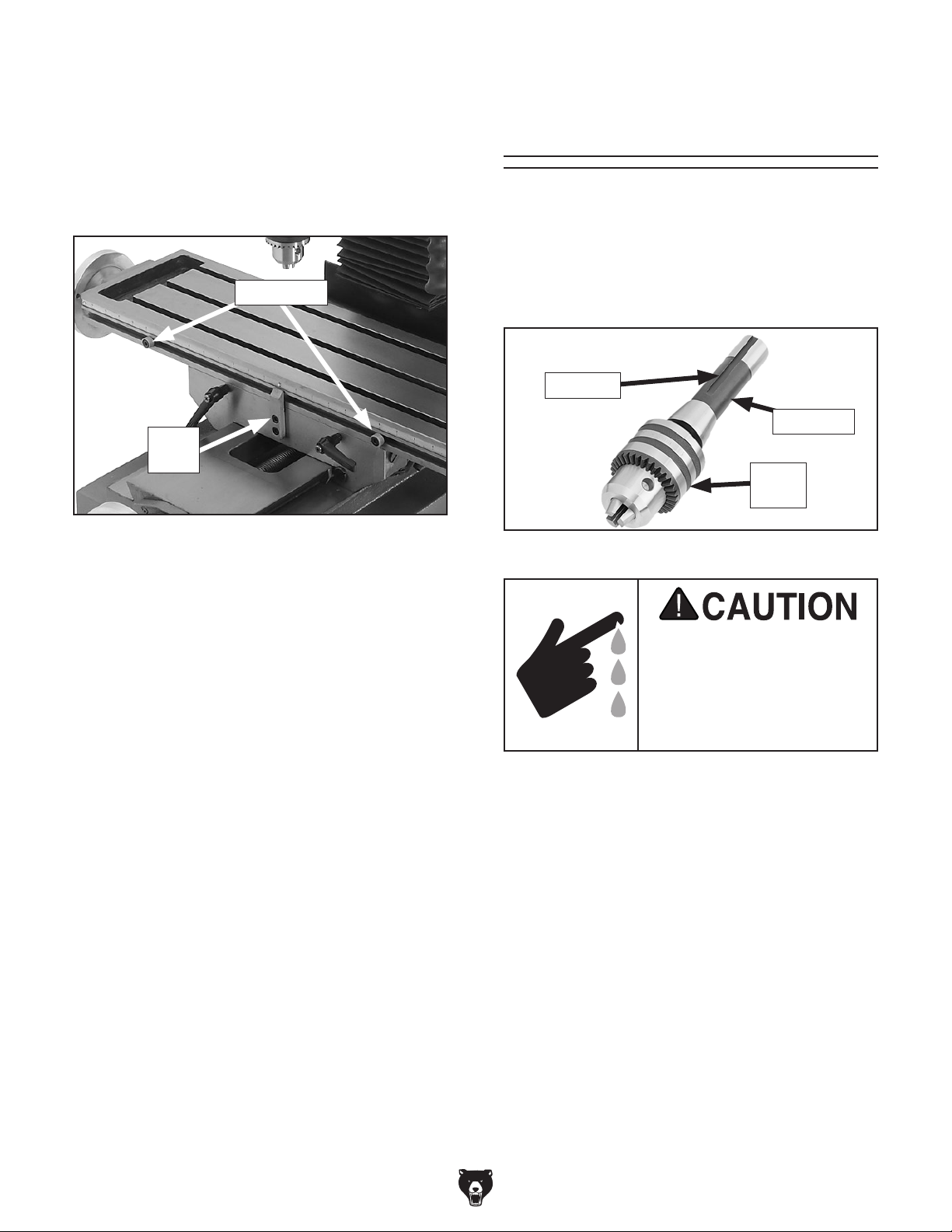
The Model G0795 includes a 3–16mm drill chuck
with an R-8 arbor (see Figure 22). The R-8 arbor
is precision-ground, and features a tool slot for
easy, secure alignment in the mill/drill spindle.
The tapered R-8 arbor end joins securely with the
drill chuck to support tooling from 3–16mm.
Tool Slot
R-8 Arbor
Drill
Chuck
Figure 22. Drill chuck joined with R-8 arbor.
Cutting tools are sharp and
can easily cause laceration
injuries. Always protect
your hands with leather
gloves or shop rags when
handling cutting tools.
Installing Tooling
Tools Needed Qty
Wrench 16mm ................................................... 1
Spindle Wrench.................................................. .... 1
To install tooling:
1. DISCONNECT MACHINE FROM POWER!
2. Remove drawbar cap, as shown in Figure 23.
-24-
Model G0795 (Mfd. Since 02/15)
Page 27
3. Install drawbar (see Figure 4 on Page 12).
4. Position tool alignment slot (see Page 24)
with pin inside spindle, then insert tooling into
spindle until it contacts drawbar.
Removing Tooling
Tools Needed Qty
Wrench 16mm ................................................... 1
Spindle Wrench ................................................. 1
Brass Head or Dead Blow Hammer .................. 1
5. Working from top end, thread drawbar by
hand into tooling until snug.
6. Place 16mm wrench over drawbar, then use
spindle wrench on spindle flats (see Figure
23) to keep spindle from rotating.
Drawbar
Spindle
Flats
Figure 23. Location of spindle flats and drawbar.
7. Tighten drawbar and re-install drawbar cap.
To remove tooling:
1. DISCONNECT MACHINE FROM POWER!
2. Remove drawbar cap.
3. Place spindle wrench over spindle flats to
keep the spindle from rotating, and use
16mm wrench to loosen drawbar one full
rotation.
Note: Do not fully unthread tooling from
drawbar or the drawbar and tool threads
could be damaged in the next step.
4. Tap top of drawbar with hammer to unseat
taper.
5. Hold onto tooling with one hand and fully
unthread drawbar with the other hand.
Do not overtighten drawbar. Overtightening
makes tool removal difficult and may damage arbor and threads.
Model G0795 (Mfd. Since 02/15)
-25-
Page 28

Setting Spindle
Speed
Using the correct spindle speed is important for
safe and satisfactory results, as well as maximizing tool life.
To set the spindle speed for your operation, you
will need to (1) determine the best spindle speed
for the cutting task, and (2) configure the spindle
speed levers to produce the required speed.
Determining Spindle Speed
Many variables affect the optimum spindle speed
to use for any given operation, but the two most
important are the recommended cutting speed
for the workpiece material and the diameter of
the cutting tool, as noted in the formula shown in
Figure 24.
Setting Spindle Speed
Use the chart below or the one on the headstock
when setting the spindle speed. With the spindle
completely stopped, position the high/low range
and spindle speed knobs as indicated by the
spindle speed chart (see Figure 25) to set the
desired spindle RPM.
Note: If necessary, rotate the spindle a little by
hand to mesh the gears when changing speeds.
Spindle Speed High/Low
Range Lever
115 RPM L 1
220 RPM L 2
320 RPM L 3
600 RPM H 1
112 0 R P M H 2
170 0 R PM H 3
Spindle
Speed Lever
*Recommended
Cutting Speed (FPM) x 12
Tool Dia. (in inches) x 3.14
Spindle
=
Speed
(RPM)
*Double if using carbide cutting tool
Figure 24. Spindle speed formula for mill/drills.
Cutting speed, typically defined in feet per minute
(FPM), is the speed at which the edge of a tool
moves across the material surface.
A recommended cutting speed is an ideal speed
for cutting a type of material in order to produce
the desired finish and optimize tool life.
The books Machinery’s Handbook or Machine
Shop Practice, and some internet sites, provide excellent recommendations for which cutting
speeds to use when calculating the spindle speed.
These sources also provide a wealth of additional
information about the variables that affect cutting
speed and they are a good educational resource.
High/Low
Range Knob
Spindle Speed
Knob
Figure 25. Spindle speed controls.
Change spindle speed ONLY when the
spindle is completely stopped. Otherwise,
machine damage could occur.
Also, there are a large number of easy-to-use
spindle speed calculators that can be found on
the internet. These sources will help you take into
account the applicable variables in order to determine the best spindle speed for the operation.
-26-
Model G0795 (Mfd. Since 02/15)
Page 29
Using Tapping Mode
8. Apply any appropriate tapping fluid to contact
point on workpiece.
When the mode switch is set to "Ta p," the spindle
rotates clockwise as the tap is lowered into the
predrilled hole in the workpiece. Once the depth
stop is reached, the spindle automatically changes directions and rotates counterclockwise to
unthread the tap from the hole.
Important: Pilot holes must be drilled prior to
beginning any tapping operation.
To use the tapping mode:
1. DISCONNECT MACHINE FROM POWER!
2. Clamp workpiece to work table.
3. Install tap.
4. Select spindle speed of 115 RPM (see Setting
Spindle Speed on Page 26, if necessary).
5. Loosen quill lock lever and downfeed selector
knob until coarse downfeed handle moves up
and down freely.
9. Connect machine to power.
10. Rotate mode switch to "Tap."
11. Press "Left" button to engage spindle.
12. Using coarse downfeed handle, slowly lower
tap into hole until tap begins threading into
workpiece. Release the coarse downfeed
handle, allowing tap to travel downward on its
own.
Tap will self-thread until the depth stop is
reached. When depth stop is reached, spindle rotation will automatically reverse and tap
will unthread from hole.
13. Turn machine OFF.
6. Adjust headstock elevation (if necessary), so
tap is just above workpiece.
7. Set depth stop (see Figure 26) to workpiece
hole depth.
Mode
Switch
Depth
Quill Lock
Lever
Adjustment
Knob
Figure 26. Locations of controls for tapping
operation.
Stop
Downfeed
Selector
Knob
Model G0795 (Mfd. Since 02/15)
-27-
Page 30
SECTION 5: ACCESSORIES
Installing unapproved accessories may
order online at www.grizzly.com or call 1-800-523-4777
cause machine to malfunction, resulting in
serious personal injury or machine damage.
To reduce this risk, only install accessories
recommended for this machine by Grizzly.
NOTICE
Refer to our website or latest catalog for
additional recommended accessories.
SB1365 —South Bend Lathe Way Oil, 12 Oz.
T23962—ISO 68 Moly-D Machine/Way Oil 5-Gal.
T23963—ISO 32 Moly-D Machine Oil 5-Gal.
T26685—ISO 32 Moly-D Machine Oil, 1-Gal.
Moly-D oils are some of the best we've found for
maintaining the critical components of machinery
because they tend to resist run-off and maintain
their lubricity under a variety of conditions—as
well as reduce chatter or slip. Buy in bulk and
save with 5-gallon quantities.
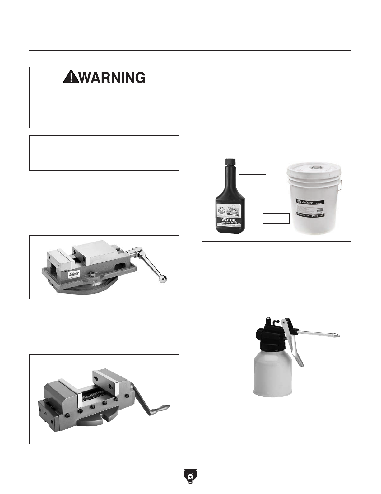
G7156—4" (3 5⁄8") Precision Milling Vise
G7154—5" (4
G7155—6" (5
Swiveling Milling Vises feature perfectly aligned,
precision ground jaws, large Acme
easy to read 0°–360° scales.
Figure 27. G7154 Precision Milling Vise.
H7576—Precision Self-Centering Vise
Both jaws on this precision vise move in equal
and opposite directions so vise remains centered
with the milling machine spindle.
1
⁄2") Precision Milling Vise
5
⁄8") Precision Milling Vise
®
screws and
SB1365
T23963
Figure 29. 12 oz. way oil & 5 gal. machine oil.
H7615—High-Pressure Oil Can, 5 Oz.
Whether you are lubricating cutting tools or maintaining machinery in top operating condition, you
will appreciate this High Pressure Oil Can. Holds
5 ounces of oil and has a trigger-activated, highpressure pump.
Figure 30. H7615 High Pressure Oil Can.
Figure 28. H7576 Specialty Milling Vise.
-28-
Model G0795 (Mfd. Since 02/15)
Page 31
order online at www.grizzly.com or call 1-800-523-4777
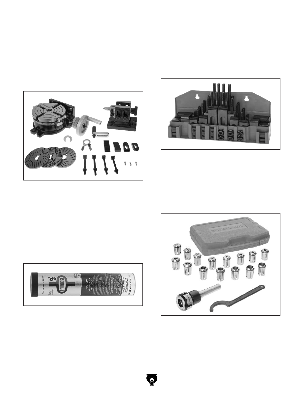
H7527— 6" Rotary Table w/ Div. Plates
Use this 6" rotary table in either the horizontal
or vertical position for a variety of milling applications and with the set of dividing plates and
adjustable tailstock, your milling applications are
nearly unlimited. With 4 degree table movement
per handle rotation and 20 second vernier scale,
control is very accurate and precise. Also includes
3
⁄8" clamping set for the 4-slot table. Everything
a
you need in one great set!
Figure 31. H7527 6" Rotary Table w/Div. Plates.
T23964—Armor Plate with Moly-D MultiPurpose Grease, 14.5 oz. (NLGI#2 Equivalent)
Armor Plate with Moly-D is a rich green moly
grease that provides excellent stability and unsurpassed performance under a wide range of temperatures and operating conditions. Armor Plate
grease is entirely unique due to the fact that the
moly in it is solubilized, which provides superior performance to other greases containing the
black solid form of molybdenum disulfide.
T26485—58-Pc. Clamping Kit
This clamping kit includes: (24) studs (four studs
each: 3", 4", 5", 6", 7", and 8" long), (6) step block
pairs, (6) T-nuts, (6) flange nuts, (4) coupling nuts,
and (6) end hold-downs. The Model T26485 set
7
⁄16" T-slots and includes 3⁄8"-16 studs. Racks
fits
can be bolted to the wall or side of machine for
easy access.
Figure 33. T26485 58-Pc. Clamping Kit.
®
SB1348—South Bend
SB1349—South Bend
Get true South Bend
8-Pc. R-8 Collet Set
®
16-Pc. R-8 Collet Set
®
quality and precision with
one of these Quick-Change Collet Sets. Each set
includes hardened and precision-ground spring
collets for maximum holding power, collet chuck,
spanner wrench, and protective moulded case.
Figure 32. T23964 Armor Plate with Moly-D
Multi-Purpose Grease.
Figure 34. Model SB1349 South Bend 16-Pc.
R-8 Collet Set.
Model G0795 (Mfd. Since 02/15)
-29-
Page 32

G5758—5" x 7" x 3 3⁄4" Tilt Table
G5759—7" x 10" x 5" Tilt Table
Set your work at any angle from -45° to +45° with
these sturdy Tilt Tables. Heavy-duty construction
7
includes
cision base.
⁄16" T-slots, two locking screws, and pre-
1
⁄2 " mounting slots.
T24799 —1-2-3 Precision Parallel Blocks
T24800—2-4-6 Precision Parallel Blocks
These blocks are extremely handy for layout and
set up work. Matched blocks are hardened and
precision ground so all six sides are square to
within 0.0003".
T24799
T24800
Figure 35. G5758 Tilt Table.
G9806—Dial Indicator 0.05" Range x 0.0001"
1
H3326—Digital Indicator
⁄2" Range x 0.0005"
If your measuring requirements call for supreme
accuracy within a short range, this is the Dial
Indicator for you. Graduations are 0.0001" (one
ten thousandth of an inch) and range is 0.05" (five
hundredths of an inch). Fits all dial indicator magnetic bases.
G9806
H3326
Figure 37. T24799 and T24800 Precision
Parallel Blocks.
H5939—Grizzly 18-Pc. R-8 Boring Head Set
This all-inclusive set features a precision 2" boring head, R-8 shank, 9 carbide-tipped boring bars
1
⁄2 " shanks, graduated dial in 0.001"-, 0.05"-,
with
and 0.025" actual motion, and a carrying case.
-30-
Figure 36. Assortment of indicators.
Figure 38. H5939 2" Boring Head Set.
Model G0795 (Mfd. Since 02/15)
Page 33

H5608—V-Block Pair w/Clamps 15⁄8"
3
H5609—V-Block Pair w/Clamps 1
⁄4"
H5610—V-Block Pair w/Clamps 2"
3
H5611—V-Block Pair w/Clamps 2
⁄4"
Each V-Block pair is precision-ground and numbered to match for accuracy.
G9815—Thin Parallel Set - 10 Pairs
G5646—10-Pc. Precision Angle Block Set
Speed set-up, production and inspection with
the Grizzly Precision Angle Block Set and Thin
Parallel Set made from hardened and precisionground steel. Each set offers a wide range of
sizes for any job.
G9815
Figure 39. H5611 V-Block Pair w/Clamps
pictured.
T10168 —3" Boring Head Set
This all-inclusive set features a precision 3" boring head, R-8 shank, five-piece set of 3/4" carbide
1
tipped boring bars, five-piece set of
1
ing bars,
⁄2 " to 3⁄4" adapter, wrenches and fitted
⁄2 " HSS bor-
case.
G5646
Figure 41. G9815 Thin Parallel Set and G5646
Precision Angle Block Set.
T25702— 5-Pc. R-8 End Mill Holder Set
This all-inclusive set features a precision 3" bor-
3
ing head, R-8 shank, five-piece set of
tipped boring bars, five-piece set of
1
ing bars,
⁄2 " to 3⁄4" adapter, wrenches and fitted
⁄4" carbide
1
⁄2 " HSS bor-
case.
Figure 40. T10168 3" Boring Head Set.
Model G0795 (Mfd. Since 02/15)
Figure 42. T25702 5-Pc. R-8 End Mill Holder
Set.
-31-
Page 34

G9756—20-Pc. HSS End Mill Set
This High Speed Steel set features 2 flute and 4
flute end cutting end mills in the following sizes:
3
⁄16", 1⁄4", 5⁄16", 3⁄8", 7⁄16", 1⁄2 ", 9⁄16", 5⁄8", 11⁄16" and 3⁄4".
Sizes are marked in a durable molded case.
H5935—3-Pc. Fly Cutter Set w/
1
⁄2" Tool Bits
Here is a 3-piece Fly Cutter Set that's hard to
beat! Each is supplied with black oxide finish, a
setscrew flat and a blank high speed steel tool.
Figure 43. G9756 20-Pc. HSS End Mill Set.
G9760—20-Pc. 2 & 4 Flute TiN End Mill Set
Includes these sizes and styles in two and four
3
flute styles:
11
/16", and 3/4".
/16", 1/4", 5/16", 3/8", 7/16", 1/2", 9/16", 5/8", 3/8",
Figure 44. G9760 20-Pc. End Mill Set.
Figure 45. H5935 3-Pc. Fly Cutter Set.
Precision Parallel Block
T25212—18-Pc. Tap/Drill Set HSS UNC
T25213 —18-Pc. Tap/Drill Set HSS UNF
G9766—29-Pc. HSS Drill & Tap Set - Metric
H5615—Screw Pitch Gauge 4-84
We offer a set of taps with all the drill bits necessary to produce perfectly tapped holes, and help
ensure you get your work done right the first time
with the Grizzly Screw Pitch Gauge. Our gauge
helps determine the thread pitch of a bolt, tapped
hole, nut or screw thread insert.
T25212
-32-
H5615
Figure 46. H5615 Screw Pitch gauge and
T25212 18-Pc. Tap/Drill Set.
Model G0795 (Mfd. Since 02/15)
Page 35

SECTION 6: MAINTENANCE
To reduce risk of shock or
accidental startup, always
disconnect machine from
Cleaning &
Protecting
power before adjustments,
maintenance, or service.
Schedule
For optimum performance from your machine,
follow this maintenance schedule and refer to any
specific instructions given in this section.
Daily Check:
• Loose mounting bolts.
• Damaged saw blade.
• Worn or damaged wires.
• Clean debris and built up grime off of machine.
• Any other unsafe condition.
Every 8 Hours of Operation:
• Check/add headstock oil (Page 34).
• Lubricate ball oilers (Page 35).
• Lubricate table and column ways (Page 35).
• Lubricate quill outside surface (Page 36).
Every 40 Hours of Operation:
• Lubricate table leadscrews (Page 36).
Metal chips left on the machine that have been
soaked with water-based coolant will invite oxidation and a gummy residue build-up around the
moving parts. Use a brush and shop vacuum to
remove chips and debris from the working surfaces of the mill/drill. Never blow off the mill/drill
with compressed air, as this will force metal chips
deep into the mechanisms and may cause injury
to yourself or bystanders.
Remove any rust build-up from unpainted cast
iron surfaces of your mill/drill and treat with a nonstaining lubricant after cleaning.
Keep unpainted cast iron surfaces rust-free with
regular applications of ISO 68 way oil (see Page
28 for offerings from Grizzly).
NOTICE
The recommended lubrication is based on
light-to-medium usage. Since lubrication
helps to protect value and operation of
machine, these lubrication tasks may need
to be performed more frequently than recommended, depending on usage.
Every 90 Hours of Operation:
• Lubricate column leadscrew, nut, and pinion
gear (Page 37).
• Lubricate quill rack and pinion (Page 37).
Annually:
• Change headstock oil (Page 34).
Model G0795 (Mfd. Since 02/15)
Failure to follow reasonable lubrication
practices as instructed in this manual could
lead to premature failure of machine components and will void the warranty.
-33-
Page 36

Lubrication
3. Remove fill plug (see Figure 47).
This mill/drill requires regular lubrication to maintain smooth movement and ensure long-lasting
operation. Components not covered in this section are sealed and internally lubricated for life.
Before performing any lubrication task,
DISCONNECT MACHINE FROM POWER!
Lubrication Frequency
Lubrication Task Frequency Page
Ball Oilers Daily
Table Leadscrew Daily
Headstock Annually
Column Nut & Pinion Annually
Quill Outside Surface Daily
Quill Rack & Pinion Annually
Table & Column Ways Daily
35
36
34
37
36
37
35
Headstock
Lube Type ...Model T23962 or ISO 68 Equivalent
Lube Amount ............................................. 3
Check/Add Frequency ........... 8 hrs. of Operation
Change Frequency ................................ Annually
1
⁄4 qt.
Fill
Plug
Oil
Sight
Glass
Figure 47. Headstock oil fill plug and sight glass.
4. Place a 1-gallon or larger drain pan on table
under headstock.
5. Remove drain plug (see Figure 48) and allow
oil to drain into pan.
Drain
Plug
The headstock has the proper amount of oil when
the sight glass shown in Figure 47 is halfway full.
Follow federal, state, and local requirements for proper disposal of used oil.
Tools Needed Qty
Wrench 24mm ................................................... 1
Hex Wrench 6mm .............................................. 1
Drain Pan (1-Gallon or larger) ........................... 1
To change headstock oil:
1. Run spindle at 600 RPM for approximately 10
minutes to warm oil.
2. DISCONNECT MACHINE FROM POWER!
Figure 48. Location of headstock drain plug
(headstock tilted 90° for clarity).
6. Replace drain plug.
7. Add oil until sight glass is halfway full, then
replace fill plug.
8. Clean up any spilled oil to reduce slipping
hazards.
-34-
Model G0795 (Mfd. Since 02/15)
Page 37

Ball Oilers
Lube Type ...Model T23963 or ISO 32 Equivalent
Lube Amount ..................................... 1–2 Pumps
Lubrication Frequency ........... 8 hrs. of Operation
Table & Column Ways
Lube Type ...Model T23962 or ISO 68 Equivalent
Lube Amount ........................................Thin Coat
Lubrication Frequency ........... 8 hrs. of Operation
Proper lubrication of the handwheel ball oilers
shown in Figure 49 is done with a pump-type oil
can with a tip wide enough to seal the ball oil inlet
(see Page 28 for offerings from Grizzly). We do
not recommend using metal needle or lance-type
tips, as they can push the ball too far into the oiler,
break the spring seat, and lodge the ball in the oil
galley.
Ball Oilers
Tool Needed Qty
Hex Wrench 5mm .............................................. 1
Disconnect one side of the column way cover,
then move the table toward the front of the mill
and headstock upward to access the entire length
of the table and column ways for this procedure
(see Figures 50 and 51).
Note: Each sliding component has two dovetail
ways—one on each side of the component.
Column Way
(1 of 2)
Column Way
Cover
Figure 49. Location of handwheel ball oilers.
To lubricate ball oiler:
1. Push tip of oil can nozzle against ball oiler
and pump oil can once or twice.
Note: If you see sludge and contaminants
coming out of the lubrication area, continue
pumping oil can until the oil runs clear.
2. When finished, wipe away any excess oil.
Figure 50. Location of table and column ways.
Clean the ways with mineral spirits and shop
rags. When dry, apply a liberal coat of lubricant,
then move the sliding components through their
full path a few times to evenly distribute the oil.
Re-install the column way cover.
Table Ways
Model G0795 (Mfd. Since 02/15)
Figure 51. X- and Y-axis table ways.
-35-
Page 38
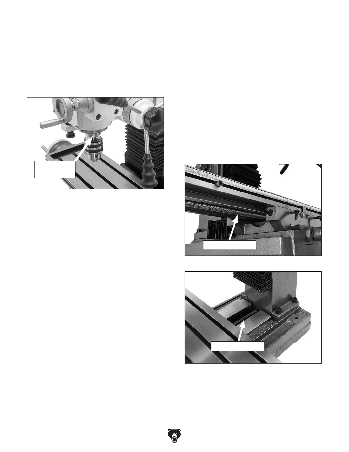
Quill Outside Surface
Lube Type ...Model T23962 or ISO 68 Equivalent
Lube Amount ........................................Thin Coat
Lubrication Frequency ........... 8 hrs. of Operation
Table Leadscrews
Lube Type ..............NLGI#2 or ISO 68 Equivalent
Lube Amount ........................................Thin Coat
Lubrication Frequency ......... 40 hrs. of Operation
Without disturbing the grease on the quill rack,
clean the outside smooth surface of the quill (see
Figure 52) with mineral spirits and shop rags.
Quill Outside
Surface
Figure 52. Outside surface of quill.
When dry, apply a thin coat of lubricant to the
smooth surface, then move the spindle up and
down to evenly distribute the oil.
Tool Needed Qty
Hex Wrench 5mm .............................................. 1
Move the table as necessary to access the entire
length of the X- and Y-axis leadscrews (see
Figures 53–54). Remove the way cover from the
base to access the Y-axis leadscrew. Use mineral
spirits, shop rags, and a brush to clean them.
When dry, use a clean brush to apply a thin coat
of oil to the leadscrew threads, then move the
table through the X- and Y-axis paths to distribute
the oil.
X-Axis Leadscrew
Figure 53. Location of X-axis leadscrew.
Y-Axis Leadscrew
Figure 54. Location of Y-axis leadscrew.
-36-
Model G0795 (Mfd. Since 02/15)
Page 39

Headstock Elevation Leadscrew &
Bevel Gears
Lube Type . . Model T23964 or NLGI#2 Equivalent
Lube Amount ........................................Thin Coat
Lubrication Frequency ......... 90 hrs. of Operation
Tool Needed Qty
Hex Wrench 3mm .............................................. 1
Remove rear cover of the column to access the
leadscrew and bevel gears (see Figure 55).
Quill Rack & Pinion
Lube Type . . Model T23964 or NLGI#2 Equivalent
Lube Amount ........................................Thin Coat
Lubrication Frequency ......... 90 hrs. of Operation
Move the quill up and down to gain full access
to the quill rack-and-pinion (see Figure 56), then
clean the teeth with mineral spirits, shop rags, and
a brush.
Crank
Bevel
Gear
Leadscrew
Leadscrew
Bevel
Gear
Figure 55. Column rear cover removed to
access headstock elevation leadscrew and bevel
gears.
Use shop rags, a stiff brush, and mineral spirits to
clean away the grease and grime from the components. When dry, apply a medium coat of grease
to the components and threads of the leadscrew
and gears. Move the headstock up and down
a few times to evenly distribute the lubricant.
Re-install rear cover.
Pinion
Rack
Figure 56. Quill rack-and-pinion.
When dry, use a brush to apply a thin coat of
grease to the teeth, then raise/lower the quill several times to evenly distribute the grease.
Note: Re-apply oil to the quill outside smooth
surface that may have been removed during the
cleaning process.
Model G0795 (Mfd. Since 02/15)
-37-
Page 40

Review the troubleshooting and procedures in this section if a problem develops with your machine. If you
need replacement parts or additional help with a procedure, call our Technical Support at (570) 546-9663.
Note: Please gather the serial number and manufacture date of your machine before calling.
SECTION 7: SERVICE
Troubleshooting
Motor & Electrical
Symptom Possible Cause Possible Solution
Machine does not
start or a breaker
trips.
Machine stalls or is
underpowered.
Machine has
vibration or noisy
operation.
1. E-Stop button depressed/at fault.
2. Plug/receptacle at fault/wired wrong.
3. Incorrect power supply voltage or circuit
size.
4. Machine fuse blown.
5. Power supply circuit breaker tripped or fuse
blown.
6. Motor wires connected incorrectly.
7. Wiring open/has high resistance.
8. ON/OFF switch at fault.
9. Spindle rotation switch at fault.
10. Start capacitor at fault.
11. Centrifugal switch at fault.
12. Motor at fault.
1. Machine undersized for task.
2. Wrong workpiece material.
3. Motor wired incorrectly.
4. Motor overheated.
5. Run capacitor at fault.
1. Machine incorrectly mounted to workbench
or floor.
2. Chuck or cutter at fault.
3. Motor or component loose.
4. Motor fan rubbing on fan cover.
5. Spindle bearings at fault.
6. Centrifugal switch is at fault.
7. Motor bearings at fault.
1. Rotate button head to reset. Replace.
2. Test for good contacts; correct the wiring.
3. Ensure correct power supply voltage and circuit
size.
4. Replace fuse/ensure no shorts.
5. Ensure circuit is sized correctly and free of shorts.
Reset circuit breaker or replace fuse.
6. Correct motor wiring connections.
7. Check/fix broken, disconnected, or corroded wires.
8. Replace switch.
9. Test/replace switch.
10. Test/replace.
11. Adjust/replace centrifugal switch if available.
12. Test/repair/replace.
1. Use correct cutter/bit; reduce feed rate; reduce
spindle RPM; use coolant if possible.
2. Use correct type/size of metal.
3. Wire motor correctly.
4. Clean motor, let cool, and reduce workload.
5. Test/repair/replace.
1. Adjust feet, shim, or tighten mounting hardware.
2. Replace unbalanced chuck; replace/resharpen
cutter; use correct feed rate.
3. Inspect/replace damaged bolts/nuts, and retighten
with thread locking fluid.
4. Fix/replace fan cover; replace loose/damaged fan.
5. Test by rotating spindle; rotational grinding/loose
shaft requires bearing replacement.
6. Replace.
7. Test by rotating shaft; rotational grinding/loose shaft
requires bearing replacement.
-38-
Model G0795 (Mfd. Since 02/15)
Page 41

Mill/Drill Operation
Symptom Possible Cause Possible Solution
Tool slips in spindle. 1. Tool is not fully drawn up into
spindle taper.
2. Taking too big of a cut.
3. Debris on tool or in spindle taper.
Breaking tools or cutters. 1. Spindle speed/feed rate is too fast.
2. Cutting tool too small.
3. Cutting tool getting too hot.
4. Taking too big of a cut.
5. Spindle extended too far down.
Workpiece vibrates or
chatters during operation.
Table is hard to move. 1. Table locks are tightened down.
Bad surface finish. 1. Spindle speed/feed rate is too fast.
1. Table locks not tight.
2. Workpiece not secure.
3. Spindle speed/feed rate is too fast.
4. Spindle extended too far down.
2. Chips have loaded up on ways.
3. Ways are dry and need lubrication.
4. Table limit stops are interfering.
5. Gibs are too tight.
2. Workpiece not secure.
3. Spindle extended too far down.
4. Dull or incorrect cutting tool.
5. Wrong rotation direction of cutting
tool.
1. Tighten drawbar.
2. Lessen depth of cut and allow chips to clear.
3. Clean collet and spindle taper.
1. Set spindle speed correctly (Page 26) or use slower
feed rate.
2. Use larger cutting tool and slower feed rate.
3. Use coolant or oil for appropriate application.
4. Lessen depth of cut and allow chips to clear.
5. Fully retract spindle and lower headstock. This
increases rigidity.
1. Tighten table locks.
2. Properly clamp workpiece on table or in vise.
3. Set spindle speed correctly (Page 26) or use a
slower feed rate.
4. Fully retract spindle and lower headstock. This
increases rigidity.
1. Make sure table locks are fully released.
2. Frequently clean away chips that load up during
milling operations.
3. Lubricate ways (Page 35).
4. Check to make sure that all table limit stops are not
in the way.
5. Adjust gibs (see Page 40).
1. Set spindle speed correctly (Page 26) or use a
slower feed rate.
2. Properly clamp workpiece on table or in vise.
3. Fully retract spindle and lower headstock. This
increases rigidity.
4. Sharpen cutting tool or select one that better suits
the operation.
5. Check for proper cutting tool rotation direction.
Model G0795 (Mfd. Since 02/15)
-39-
Page 42
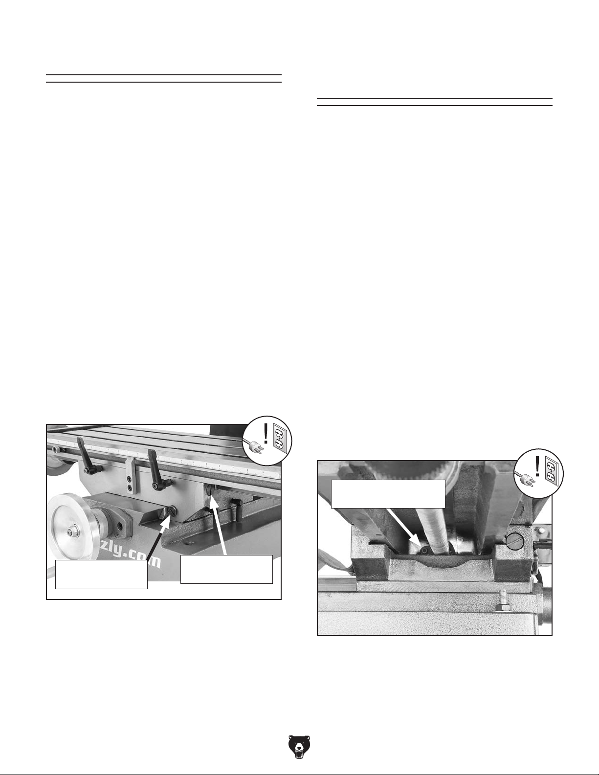
Adjusting Gibs
The gibs affect the accuracy of the work table by
restricting slide movements along their ways.
Screws on each end allow gib adjustments to
increase or decrease the friction between the sliding surfaces of the ways.
The goal of gib adjustment is to remove unnecessary sloppiness without causing binding in the
dovetail ways. Tight gibs make the movements
more accurate, but harder to perform. Loose
gibs make the movements sloppy, but easier to
perform. Many experienced machinists adjust the
gibs until there is just a slight drag in table movement.
Adjusting Leadscrew
Backlash
Tool Needed Qty
Hex Wrench 4mm (long) .................................... 1
Leadscrew backlash is the amount of free-play
movement in the leadscrew (when changing the
direction of rotation) before the attached device
begins to move.
Leadscrews must have a certain amount of backlash, but over time, this will increase with normal
wear. Generally, 0.003"–0.006" leadscrew backlash is acceptable to ensure smooth movement
and reduce the risk of premature thread wear.
DISCONNECT MACHINE FROM POWER
BEFORE ADJUSTING THE GIBS!
Make sure all table locks are loose. Then, loosen
one gib adjustment screw (see Figure 57) and
tighten the opposing screw the same amount to
move the gib, while at the same time using the
handwheels to move the table until you feel a
slight drag in that path of movement.
Y-Axis Gib Screw
(1 of 2)
X-Axis Gib Screw
(1 of 2)
The X- and Y-axis leadscrew backlash is adjusted
by using a long hex wrench to tighten/loosen the
cap screw on the leadscrew nut. This adjusts the
force that the split leadscrew nut exerts on the
leadscrew threads.
The X-axis leadscrew nut shown in Figure 58
is accessed from underneath the left side of the
table.
The Y-axis leadscrew nut is similar and is accessed
from underneath the machine base.
X-Axis Leadscrew Nut
Cap Screw
Figure 57. Location of table gib screws.
-40-
Figure 58. X-axis leadscrew nut adjusting cap
screw.
Model G0795 (Mfd. Since 02/15)
Page 43
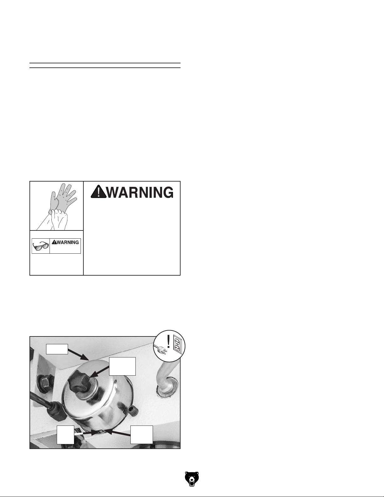
Tightening Return
Eye injury hazard! Always
Spring Tension
The return spring moves the spindle back up
when the coarse downfeed handles are released.
The tension of this spring was adjusted at the factory, but it may need to be tightened during the life
of the mill/drill.
Important: Do not perform this procedure unless
it is absolutely necessary. The high amount of
spring tension involved can make this a difficult
procedure. Return spring tension is adjusted at
the factory and should be suitable for most applications.
If the return spring should
come loose from the spring
cap and rapidly unwind,
laceration or impact injuries could occur. Always
wear safety glasses when
using this machine.
wear heavy leather gloves
and safety glasses when
adjusting the return spring
tension.
To adjust the return spring tension:
1. DISCONNECT MACHINE FROM POWER!
2. Wipe off any oil on spring cover so it does not
slip when you hold it during adjustments.
3. Mark slot on cover that engages roll pin—this
is the factory setting.
4. Put on heavy leather gloves to protect your
hands from lacerations if spring uncoils during next step.
Note: Keep a good grip on spring cover dur-
ing next step. Letting go of cover when roll
pin is not engaged will cause spring to rapidly
uncoil.
5. While holding spring cover against side of
headstock so spring will not unwind, loosen
1
thumb screw approximately
⁄4".
6. Pull cover out just enough to disengage it with
roll pin, then rotate it clockwise to engage roll
pin in next slot in cover.
7. Retighten thumb screw to secure setting.
During this procedure, you will loosen the spring
cover thumb screw (see Figure 59) just enough
to pull the cover back to clear the roll pin, then
rotate the cover clockwise to fit the roll pin in the
next slot.
Cover
Thumb
Screw
Roll
Pin
Cover
Slot
Figure 59. Return spring components.
Model G0795 (Mfd. Since 02/15)
-41-
Page 44

Tramming Spindle
After positioning the head at an angle and when
your operation requires that the spindle axis be
precisely perpendicular to the table, you must
tram or align the spindle with the table to ensure
the spindle is exactly 90° to the table.
Note: A precision-ground plate can be substituted for the parallel blocks. Keep in mind that
the farther the indicator point can be placed from
the spindle axis, the more accurate the alignment
measurements will be.
To tram spindle to table:
1. DISCONNECT MACHINE FROM POWER!
This procedure involves mounting a dial test
indicator to the quill or spindle, rotating it around
the table, and adjusting the spindle axis (Z-axis)
90° to the table X- and Y-axis, as illustrated in
Figure 60.
Spindle
Z-Axis
Y-Axis
Figure 60. Spindle Z-axis perpendicular to the
table X- and Y-axis.
We encourage you to research the many variations of spindle tramming to find the one that
works best for you. If you do not already have a
preference for performing this operation, use the
following widely-used procedure for accurately
tramming the spindle to the table.
Keep in mind that all workpiece top surfaces are
not exactly parallel with the table top. You may
choose to tram the spindle to the top surface of
the workpiece after it is mounted rather than tramming the spindle to the table.
Tools Needed Qty
Dial Test Indicator
(with at least 0.0005" resolution) ................ 1
Indicator Holder
(mounted on the quill/spindle) .................... 1
Precision Parallel Block
(at least 9" in length) ................................... 1
90º
90º
X-Axis
Table
2. Prepare mill for tramming by performing following tasks:
• Verify the table is clean by running your
hand over the top of it. If necessary, stone
the table to remove all nicks and burrs,
then clean off all debris.
• Position the table for the milling operation
you intend to perform after tramming—
preferably centered with the saddle.
• Tighten the quill lock lever used during
intended milling operations.
3. Place parallel block underneath spindle.
4. Install indicator holder in spindle or on quill,
then mount indicator so that point is as parallel to block as possible (see Figure 61).
Spindle
Dial Test
Indicator
Indicator
Holder
Parallel Block
Table
Figure 61. Dial test indicator mounted.
-42-
Model G0795 (Mfd. Since 02/15)
Page 45

5. To measure spindle alignment along X-axis,
place parallel block directly under spindle and
indicator across length of table, as illustrated
in Figure 62.
Note: If you must re-position the quill or the
knee to accommodate the above step, then
review the tasks in Step 2 to make sure the
mill is properly prepared for tramming.
Note: Keep one of the rotation lock bolts
just snug so the head does not move loosely
while you adjust it. Remember to tighten
all the rotation lock bolts after adjusting the
head.
8. Place parallel block directly under spindle
and across width of table, as illustrated in
Figure 63.
Table (Top View)
Parallel Block
Indicator Spindle
Figure 62. Parallel block and indicator positioned
for the X-axis measurement
(top view).
Note: Your general goal in the next steps
should be to get the difference of the indicator
readings between the ends of the parallel bar
down to 0.0005". However, the acceptable
variance will depend on the requirements for
your operation.
6. Rotate spindle by hand so that indicator point
rests on one end of parallel block, as illustrated in Figures 61–62, then zero the dial.
7. Rotate spindle so that indicator point rests
in same manner on other end of block, then
read dial.
— If the indicator dial still reads zero or is
within the acceptable variance, continue on
with Step 8.
— If the indicator dial has moved from zero
beyond the acceptable variance, you will
need to compensate for that amount by
rotating the head left or right. Repeat Steps
6–7 until you are satisfied with the spindle
axis alignment along the table X-axis.
Table (Top View)
Indicator
Spindle
Parallel Block
Figure 63. Parallel block and indicator positioned
for the Y-axis measurement
(top view).
9. Rotate spindle so indicator point rests on parallel bar, as illustrated in Figure 63, then zero
the dial.
10. Rotate spindle so that indicator point rests on
other end of bar in same manner, then read
dial.
— If the indicator dial still reads zero or is
within the acceptable variance, the spindle
is precisely perpendicular to the table in
both the X- and Y-axis, and the tramming
procedure is complete.
— If the indicator dial has moved from zero
beyond the acceptable variance, you will
need to compensate for that amount by tilting the head forward or backward. Repeat
Steps 9–10 until you are satisfied with
the spindle axis alignment along the table
Y-axis.
Note: Keep one of the tilt lock bolts just snug
so the head does not move loosely while you
adjust it. Remember to tighten all the tilt lock
bolts after adjusting the head.
Model G0795 (Mfd. Since 02/15)
-43-
Page 46

These pages are current at the time of printing. However, in the spirit of improvement, we may make changes to the electrical systems of future machines. Compare the manufacture date of your machine to the one
number and manufacture date of your
machine before calling. This information can be found on the main machine label.
machine
SECTION 8: WIRING
stated in this manual, and study this section carefully.
If there are differences between your machine and what is shown in this section, call Technical Support at
(570) 546-9663 for assistance BEFORE making any changes to the wiring on your machine. An updated
wiring diagram may be available. Note: Please gather the serial
Wiring Safety Instructions
SHOCK HAZARD. Working on wiring that is con-
nected to a power source is extremely dangerous.
Touching electrified parts will result in personal
injury including but not limited to severe burns,
electrocution, or death. Disconnect the power
from the machine before servicing electrical components!
MODIFICATIONS. Modifying the wiring beyond
what is shown in the diagram may lead to unpredictable results, including serious injury or fire.
This includes the installation of unapproved aftermarket parts.
WIRE CONNECTIONS. All connections must
be tight to prevent wires from loosening during
machine operation. Double-check all wires disconnected or connected during any wiring task to
ensure tight connections.
CIRCUIT REQUIREMENTS. You MUST follow
the requirements at the beginning of this manual
when connecting your machine to a power source.
WIRE/COMPONENT DAMAGE. Damaged wires
or components increase the risk of serious personal injury, fire, or machine damage. If you notice
that any wires or components are damaged while
performing a wiring task, replace those wires or
components.
MOTOR WIRING. The motor wiring shown in
these diagrams is current at the time of printing
but may not match your machine. If you find this
to be the case, use the wiring diagram inside the
motor junction box.
CAPACITORS/INVERTERS. Some capacitors
and power inverters store an electrical charge for
up to 10 minutes after being disconnected from
the power source. To reduce the risk of being
shocked, wait at least this long before working on
capacitors.
EXPERIENCING DIFFICULTIES. If you are experiencing difficulties understanding the information
included in this section, contact our Technical
Support at (570) 546-9663.
The photos and diagrams
included in this section are
best viewed in color. You
can view these pages in
color at www.grizzly.com.
-44-
Model G0795 (Mfd. Since 02/15)
Page 47
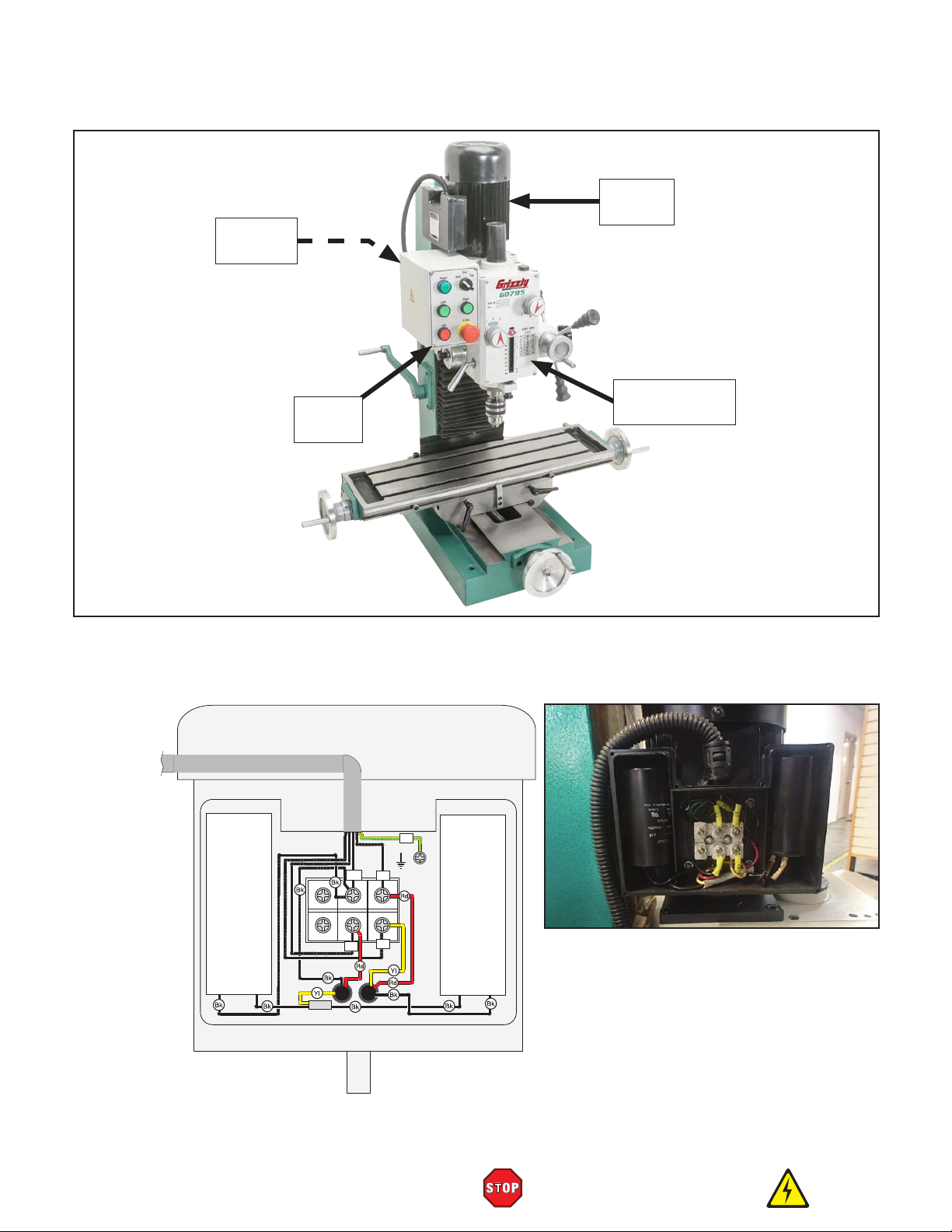
220V Motor
Ground
V1
U2
U1
PE
Start
Capacitor
100 MFD
250 VAC
Run
Capacitor
20 MFD
450 VAC
W2
Z1W1
Z2W2
V2
V1
U2
U1
Component Location
Spindle
Motor
Electrical
Panel
Limit Switches
Control
Panel
(Inside)
Electrical
Page 47
To
Panel
Spindle Motor Wiring Diagram
Figure 64. Motor Wiring
Model G0795 (Mfd. Since 02/15)
READ ELECTRICAL SAFETY
ON PAGE 44!
-45-
Page 48

Main Wiring Diagram
Mode Selector Switch
IDEK YW-E10
3
4
3
13
RIGHT Button
IDEK YW-E10
3
9
2
4
1
5
E-STOP
IDEK YW-E01
1 2
L1
Headstock
Upper Limit Switch
OMRON
V-156-1C25
16
17
3
4
14
10
POWER Light
ONPOW Y090
3
3
1
LEFT Button
IDEK YW-E10
1 2
2
4
2
N
5
43
43
15
Control Panel
(Viewed From Back)
3
3
4
4
4
4
6
9
OFF Button
IDEK YW-E01
Figure 65. Limit switch
1
1
1 2
2
wiring.
L1
17
RELAY
Schneider
Electric
RXM2LB2P7
230VAC
W2
F15A250V
L
10
11
N
Fuse
13
15
230VAC
50/60HZ
Electrical Panel
(Viewed From Front)
Lower Limit Switch
OMRON
6
A1
L1
8
L1
1L1
Schneider Electric
LC1E12N
53NO
61NC
4
11
KA0
5
54NO
2T1 6T3 14NO4T2
62NC
N
15
N
5L3 13NO3L2
12
A1
A2
12
N
1L1 5L3 13NO3L2
Schneider Electric
4
L1
53NO
LC1E12N
N
4
61NC
8
7
KA0
9
62NC
54NO
2T1 6T3 14NO4T2
L1
N
A2
16
V-156-1C25
14
16
13
7
V1
U1
U2
14
V1
U1
U2
13
Electrical Box
PE
Ground
PE
-46-
Hot
Hot
Ground
G
220
VAC
6-15 Plug
(As Recommended)
READ ELECTRICAL SAFETY
ON PAGE 44!
To Motor
Page 45
Model G0795 (Mfd. Since 02/15)
Page 49

Main Wiring Photos
Figure 66. Control panel wiring.
Model G0795 (Mfd. Since 02/15)
Figure 67. Electrical panel wiring.
READ ELECTRICAL SAFETY
ON PAGE 44!
-47-
Page 50

SECTION 9: PARTS
Please Note: We do our best to stock replacement parts whenever possible, but we cannot guarantee that all parts shown here
are available for purchase. Call (800) 523-4777 or visit our online parts store at www.grizzly.com to check for availability.
Table & Base
39
40
27
26
19
26
11-1
13
12
11
10
33
37
34
32
36
34
28
19
27
26
26
29
15
14
4
3
2
8
35
5
32
6
25
33
31
30
2
24
5
7
22
23
2
5
21
35
8
23
5
6
2
20
8
17
9
16
9
37
16
19
15
38
14
15
18
14
9
10
11-1
11
12
13
9
27
10
13
12
11
11-1
1
-48-
Model G0795 (Mfd. Since 02/15)
Page 51

Base Parts List
REF PART # DESCRIPTION REF PART # DESCRIPTION
1 P0795001 BASE CASTING 21 P0795021 Y-AXIS GIB
2 P0795002 GIB SCREW M6-1 X 25 22 P0795022 X-AXIS STOP BLOCK W/ INDICATOR
3 P0795003 WORKTABLE GIB 23 P0795023 ADJUSTABLE HANDLE 80L M8-1.25 X 25
4 P0795004 WORKTABLE SADDLE 24 P0795024 CAP SCREW M8-1.25 X 50
5 P0795005 DOWEL PIN 6 X 12 25 P0795025 Y-AXIS LEADSCREW NUT
6 P0795006 ADJUSTABLE HANDLE 80L M8-1.25 X 25 26 P0795026 CAP SCREW M6-1 X 20
7 P0795007 Y-AXIS LEADSCREW 27 P0795027 INT THREADED TAPER PIN 6 X 12
8 P0795008 KEY 5 X 5 X 16 28 P0795028 X-AXIS LEADSCREW BRACKET (L)
9 P0795009 THRUST BEARING 51103 29 P0795029 X-AXIS DIAL SEAT
10 P0795010 LOCK NUT M10-1.5 30 P0795030 X-AXIS LEADSCREW
11 P0795011 REVOLVING HANDLE 31 P0795031 X-AXIS TABLE SCALE
11-1 P0795011-1 HANDLE SCREW M10-1.5 X 12, 12 X 73 32 P0795032 SQUARE NUT M6-1
12 P0795012 FLAT WASHER 10MM 33 P0795033 CAP SCREW M6-1 X 14
13 P0795013 HANDWHEEL 125MM, KEYED BORE 10MM 34 P0795034 STOP BLOCK
14 P0795014 HANDWHEEL SPRING 35 P0795035 CAP SCREW M5-.8 X 20
15 P0795015 GRADUATED DIAL 36 P0795036 X-AXIS LEADSCREW NUT
16 P0795016 GRADUATED DIAL SEAT 37 P0795037 CAP SCREW M6-1 X 25
17 P0795017 CAP SCREW M8-1.25 X 20 38 P0795038 X-AXIS LEADSCREW BRACKET (R)
18 P0795018 Y-AXIS LEADSCREW BRACKET 39 P0795039 HOSE CONNECTOR M16-2 X 15
19 P0795019 BALL OILER 6MM PRESS-IN 40 P0795040 TABLE
20 P0795020 CAP SCREW M6-1 X 12
Model G0795 (Mfd. Since 02/15)
-49-
Page 52

108
Headstock
193-2
193-7
192
191
190
206
207
208
209
210
184
211
193-1
214
215
193-4
193-6
150
149
193-3
193-5
193-9
176
176
205
204
186
203
116
202
212
213
147
148
151
146
157
161
157
156
155
154
153
152
145
193-8
193-10
198
176
163
162
159
142
143
144
140
158
135
164
160
142
139
138
137
136
141
134
193
133
164
132
195
161
194
196
197
199
172
175
125
188
198
200
169
192
201
174
173
169
124
126
127
128
129
130
131
168
165
123
172
170
171
121
122
166
114
191
190
176
189
187
186
116
184
183
182
181
180
179
178
177
176
115
122
116
117
119
101
102
103
104
105
106
106
103
107
109
110
110
111
112
113
114
115
116
117
118
119
120
121
118
-50-
Model G0795 (Mfd. Since 02/15)
Page 53

Headstock Parts List
REF PART # DESCRIPTION REF PART # DESCRIPTION
101 P0795101 DRAWBAR CAP 146 P0795146 FLAT WASHER 6MM
102 P0795102 SEAL SEAT 147 P0795147 KNOB BOLT M6-1 X 14
103 P0795103 INT RETAINING RING 62MM 148 P0795148 SPINDLE END CAP
104 P0795104 BEARING SEAT 149 P0795149 SPINDLE
105 P0795105 EXT RETAINING RING 35MM 150 P0795150 TAPERED ROLLER BEARING 30207
106 P0795106 BALL BEARING 6006-OPEN 151 P0795151 PHLP HD SCR M5-.8 X 10
107 P0795107 GEAR 57T 152 P0795152 COIL SEAT
108 P0795108 SPINDLE HOUSING 153 P0795153 FLAT HD SCR M5-.8 X 10
109 P0795109 KEY 8 X 8 X 14 154 P0795154 DRAIN PLUG M12-1
110 P0795110 OIL SEAL 30 X 42 X 7 155 P0795155 HEADSTOCK CASTING
111 P0795111 OIL SEAL SLEEVE 156 P0795156 GEAR COLLAR (FRONT)
112 P0795112 PHLP HD SCR M5-.8 X 16 157 P0795157 ROLL PIN 4 X 10
113 P0795113 OIL SEAL SLEEVE GASKET 158 P0795158 SET SCREW M6-1 X 10 LONG DOG-PT
114 P0795114 SET SCREW M6-1 X 10 CONE-PT 159 P0795159 COPPER BLOCK (FRONT)
115 P0795115 GEAR KNOB 160 P0795160 SET SCREW M6-1 X 8
116 P0795116 STEEL BALL 6.5MM 161 P0795161 HEX NUT M6-1
117 P0795117 COMPRESSION SPRING .8 X 5 X 25 162 P0795162 COPPER BLOCK (REAR)
118 P0795118 GEAR KNOB LABEL 163 P0795163 GEAR COLLAR (REAR)
119 P0795119 SET SCREW M8-1.25 X 8 164 P0795164 FLAT HD CAP SCR M4-.7 X 20
120 P0795120 CONTROL FACEPLATE 165 P0795165 SWITCH BRACKET
121 P0795121 SPEED SHIFT SHAFT 166 P0795166 PHLP HD SCR M4-.7 X 8
122 P0795122 BUTTON HD CAP SCR M4-.7 X 6 168 P0795168 QUILL LOCK SLEEVE (R)
123 P0795123 FLAT WASHER 4MM 169 P0795169 OIL SEAL 10 X 22 X 7
124 P0795124 DEPTH INDICATOR 170 P0795170 SET SCREW M6-1 X 20 LONG DOG-PT
125 P0795125 DEPTH ADJ NUT M12-1.5 171 P0795171 HEX NUT M6-1
126 P0795126 DEPTH ADJ SCREW M12-1.5, M12-2 172 P0795172 RIVET 2.5 X 5 FLUTED
127 P0795127 HEX NUT M14-2 THIN 173 P0795173 OIL SIGHT M16 X 1.5
128 P0795128 SPINDLE SLEEVE 174 P0795174 HEADSTOCK ANGLE GAUGE
129 P0795129 DEPTH SUPPORT RING 175 P0795175 SET SCREW M5-.8 X 10 CONE-PT
130 P0795130 SCREW SLEEVE M14-2 176 P0795176 BALL BEARING 6001-OPEN
131 P0795131 ROLL PIN 3 X 14 177 P0795177 SPACER
132 P0795132 KNURLED KNOB 178 P0795178 GEAR 27T
133 P0795133 LOCK WASHER 6MM 179 P0795179 GEAR 21T
134 P0795134 HEX NUT M6-1 180 P0795180 GEAR 36T
135 P0795135 CAP SCREW M6-1 X 35 181 P0795181 SPINDLE SHAFT
136 P0795136 TAPERED ROLLER BEARING 30205 182 P0795182 KEY 5 X 5 X 70
137 P0795137 TAPERED WASHER 25MM 183 P0795183 KEY 5 X 5 X 36
138 P0795138 SPANNER NUT M25-1.5 184 P0795184 SET SCREW M5-.8 X 10 CONE-PT
139 P0795139 QUILL LOCK SLEEVE (L) 186 P0795186 COMPRESSION SPRING
140 P0795140 QUILL LOCK HANDLE 187 P0795187 GEAR 46T
141 P0795141 SET SCREW M10-1.5 X 35 DOG-PT 188 P0795188 KEY 5 X 5 X 16
142 P0795142 ROLL PIN 3 X 12 189 P0795189 GEAR 18T
143 P0795143 EXT RETAINING RING 18MM 190 P0795190 INT RETAINING RING 28MM
144 P0795144 FLAT COIL SPRING 191 P0795191 HEADSTOCK PLUG
145 P0795145 RETURN SPRING HOUSING
Model G0795 (Mfd. Since 02/15)
-51-
Page 54

Headstock Parts List
REF PART # DESCRIPTION REF PART # DESCRIPTION
192 P0795192 O-RING 23.7 X 3.5 P24 199 P0795199 TAPER PIN 8 X 35
193 P0795193 MOTOR 1HP 220V 1-PH 200 P0795200 OIL PLUG BOLT M16-1.5 X 15
193-1 P0795193-1 MOTOR FAN COVER 201 P0795201 HEADSTOCK COVER
193-2 P0795193-2 MOTOR FAN 202 P0795202 MOTOR SHAFT
193-3 P0795193-3 CAPACITOR COVER 203 P0795203 BALL BEARING 6006-OPEN
193-4 P0795193-4 R CAPACITOR 20M 450V 1-1/2 X 3-1/4 204 P0795204 INT RETAINING RING 55MM
193-5 P0795193-5 S CAPACITOR 100M 250V 1-1/2 X 3-1/4 205 P0795205 OIL SEAL 30 X 55 X 10
193-6 P0795193-6 CENTRIFUGAL SWITCH 206 P0795206 EXT RETAINING RING 16MM
193-7 P0795193-7 CONTACT PLATE 207 P0795207 GEAR 23T
193-8 P0795193-8 JUNCTION BOX 208 P0795208 KEY 6 X 6 X 25
193-9 P0795193-9 BALL BEARING 6204ZZ 209 P0795209 GEAR 38T
193-10 P0795193-10 BALL BEARING 6204ZZ 210 P0795210 GEAR 32T
194 P0795194 KEY 6 X 6 X 36 211 P0795211 MOTOR GEAR SHAFT
195 P0795195 CAP SCREW M8-1.25 X 12 212 P0795212 KEY 5 X 5 X 60
196 P0795196 MOTOR MOUNTING PLATE 213 P0795213 KEY 5 X 5 X 10
197 P0795197 CAP SCREW M6-1 X 16 214 P0795214 GEAR 41T
198 P0795198 CAP SCREW M6-1 X 40 215 P0795215 SPACER
-52-
Model G0795 (Mfd. Since 02/15)
Page 55

323
304
REF PART # DESCRIPTION REF PART # DESCRIPTION
Downfeed Handle
318
320
322
319
321
312
317
316
315
313
314
309
311
308
310
302
303
307
306-1
306
301
304
305
301 P0795301 DOWNFEED GEAR SHAFT 312 P0795312 WORM SHAFT COVER
302 P0795302 DOWNFEED GEAR SHAFT HOUSING 313 P0795313 CAP SCREW M4-.7 X 16
303 P0795303 WORM SHAFT 314 P0795314 HANDWHEEL CURVED PLATE SPRING
304 P0795304 BALL BEARING 6200-OPEN 315 P0795315 HANDLE GRIP
305 P0795305 SPACER 316 P0795316 SHLDR STUD-UDE M10-1.5 X 145, 11MM
306 P0795306 REVOLVING HANDLE 317 P0795317 KNOB BOLT M10-1.5 X 35
306-1 P0795306-1 HANDLE SCREW M6-1 X 10, 8 X 46 318 P0795318 COARSE DOWNFEED HUB
307 P0795307 FINE DOWNFEED HANDWHEEL 64MM 319 P0795319 COMPRESSION SPRING
308 P0795308 SET SCREW M6-1 X 8 320 P0795320 EXT RETAINING RING 25MM
309 P0795309 SET SCREW M6-1 X 5 321 P0795321 WORM GEAR
310 P0795310 HANDWHEEL SEAT 322 P0795322 CAP SCREW M8-1.25 X 55
311 P0795311 GRADUATED DIAL 323 P0795323 KEY 8 X 8 X 16
Model G0795 (Mfd. Since 02/15)
-53-
Page 56

Column
418-1
REF PART # DESCRIPTION REF PART # DESCRIPTION
427
428
425
420
419
418
429
426
430
425
424
415
431
415
423
410
416
417
422
409
421
432
433
413
414
435
434
412
411
410
409
401
436
437
402
436
404
442
403
443
405
442
407
406
408
438
439
440
439
441
401 P0795401 COLUMN 422 P0795422 BALL BEARING 6002-OPEN
402 P0795402 HEADSTOCK MOUNT 423 P0795423 SMALL BEVEL GEAR
403 P0795403 HEX BOLT M12-1.75 X 55 424 P0795424 BEVEL PAD
404 P0795404 FLAT WASHER 12MM 425 P0795425 THRUST BEARING 51202
405 P0795405 HEADSTOCK SEAT 426 P0795426 BEARING SEAT
406 P0795406 CAP SCREW M6-1 X 25 427 P0795427 CAP SCREW M6-1 X 14
407 P0795407 LOCK WASHER 12MM 428 P0795428 FLAT WASHER 14MM
408 P0795408 HEX NUT M12-1.75 429 P0795429 FLANGE NUT M14-2
409 P0795409 CAP SCREW M6-1 X 14 430 P0795430 TOP COVER
410 P0795410 FLAT WASHER 6MM 431 P0795431 BUTTON HD CAP SCR M4-.7 X 8
411 P0795411 BEVEL GEAR 432 P0795432 Z-AXIS LEADSCREW
412 P0795412 BUSHING 433 P0795433 CAP SCREW M5-.8 X 8
413 P0795413 Z-AXIS LEADSCREW BRACKET 434 P0795434 BACK COVER
414 P0795414 CAP SCREW M6-1 X 20 435 P0795435 Z-AXIS LEADSCREW NUT
415 P0795415 KEY 5 X 5 X 16 436 P0795436 GIB ADJUSTMENT SCREW M6-1 X 25
416 P0795416 CRANK SHAFT 437 P0795437 COLUMN GIB
417 P0795417 EXT RETAINING RING 15MM 438 P0795438 Z-AXIS WAY COVER UPPER PLATE
418 P0795418 REVOLVING HANDLE 439 P0795439 PHLP HD SCR M4-.7 X 6
418-1 P0795418-1 HANDLE SCREW M10-1.5 X 12, 12 X 73 440 P0795440 Z-AXIS WAY COVER
419 P0795419 Z-AXIS CRANK HANDLE 441 P0795441 Z-AXIS WAY COVER LOWER BRACKET
420 P0795420 SET SCREW M8-1.25 X 8 442 P0795442 PHLP HD SCR M5-.8 X 12
421 P0795421 TAPER PIN 6 X 18 443 P0795443 Y-AXIS WAY COVER
-54-
Model G0795 (Mfd. Since 02/15)
Page 57
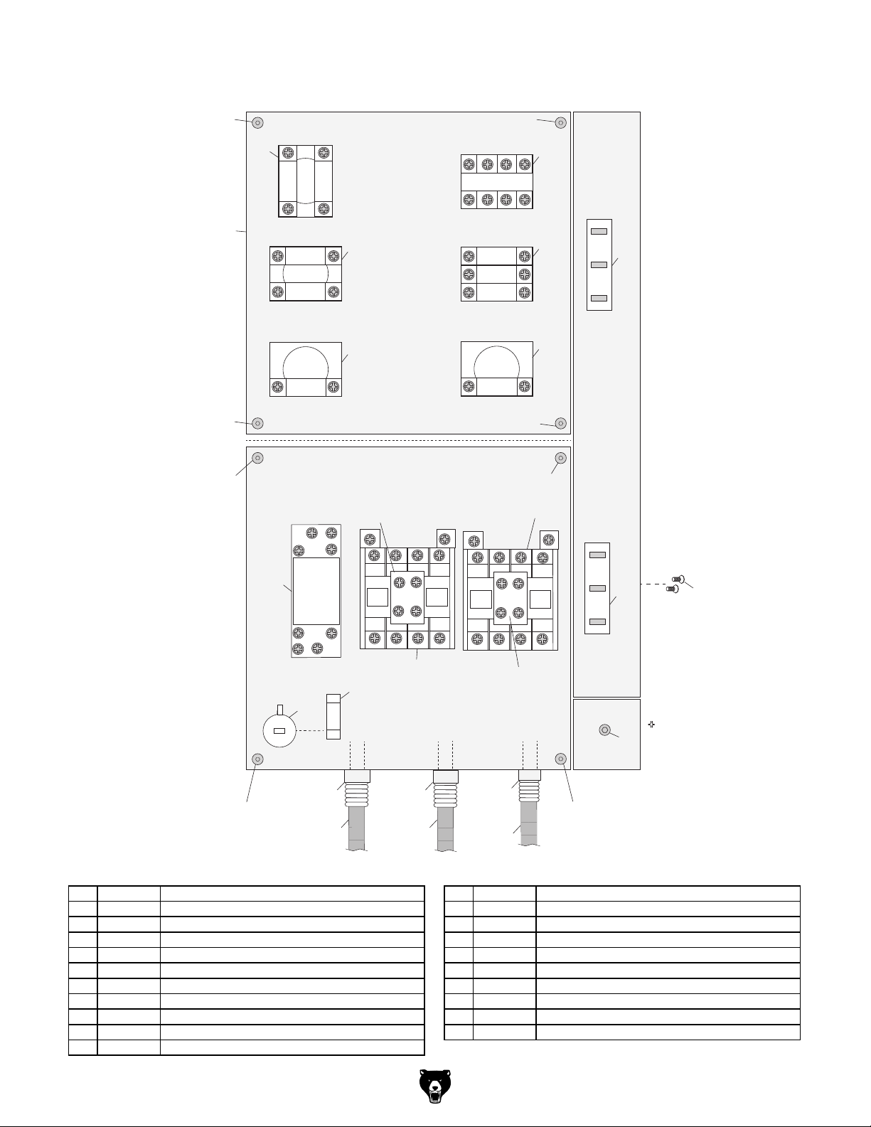
Electrical Parts
511
515
511
511
501
RIGHT BUTTON
507
MODE SWITCH
4
3
4
3
4
3
12
E-STOP
1 2
Control Panel
(Viewed From Back)
516
505
521
A1
Contactor
1L1
53NO
54NO
2T1 6T3 14NO4T2
KA0
61NC
5L3 13NO3L2
62NC
511
POWER BUTTON
LEFT BUTTON
43
43
1 2
OFF BUTTON
1 2
511
Electrical Panel
(Viewed From Front)
A1
Contactor
A2
1L1 5L3 13NO3L2
53NO
61NC
KA0
62NC
54NO
2T1 6T3 14NO4T2
508
502
504
506
511
A2
Head Stock
Upper Limit
Switch
503
Lower Limit
Switch
503
511
508
521
509
517
Fuse Holder
Fuse
512
513
514
511
519518
REF PART # DESCRIPTION REF PART # DESCRIPTION
501 P0795501 MODE SWITCH IDEK YW-E10 512 P0795512 STRAIN RELIEF 20MM TYPE-5
502 P0795502 POWER INDICATOR LIGHT ONPOW Y090 513 P0795513 STRAIN RELIEF 20MM TYPE-3
503 P0795503 LIMIT SWITCH OMRON V-156-1C25 514 P0795514 STRAIN RELIEF 16MM TYPE-5
504 P0795504 LEFT BUTTON SWITCH IDEK YW-E10 22MM GRN 515 P0795515 ELECTRICAL BOX
505 P0795505 E-STOP IDEK YW-E01 22MM 516 P0795516 RIGHT BUTTON SWITCH YW-E10 22MM GRN
506 P0795506 OFF BUTTON SWITCH IDEK YW-E01 22MM RED 517 P0795517 FUSE HOLDER 15A 250V
507 P0795507 RELAY SCHN RXM2LB2P7230V 518 P0795518 CONDUIT 16MM X 18"
508 P0795508 CONTACTOR SCHN LC1E1210 220V 519 P0795519 POWER CORD 16G 3W 68"
509 P0795509 FUSE 15A 250V 0.18" FAST-ACTING, GLASS 520 P0795520 CONDUIT 13MM X 9-1/2"
510 P0795510 CAP SCREW M5-.8 X 10 521 P0795521 AUX CONTACT BLOCK SCHN LAEN11N 220V
511 P0795511 BUTTON HD CAP SCR M4-.7 X 6
520
Electrical Box
510
511
Model G0795 (Mfd. Since 02/15)
-55-
Page 58

Accessories
612
611
610
601
613
609
602
603
608
614
604
605
606
607
REF PART # DESCRIPTION REF PART # DESCRIPTION
601 P0795601 DRILL CHUCK KEY 5/16" STD 11T SD-5/8" 608 P0795608 SPINDLE WRENCH 40MM
602 P0795602 DRILL CHUCK ARBOR R8-B16 609 P0795609 DRAWBAR 7/16-20 X 12"
603 P0795603 BOTTLE FOR OIL 610 P0795610 T-BOLT M10-1.5 X 60
604 P0795604 SCREWDRIVER PHILLIPS #2 611 P0795611 HEX NUT M10-1.5
605 P0795605 SCREWDRIVER FLAT #2 612 P0795612 FLAT WASHER 10MM
606 P0795606 HEX WRENCH SET 5-PC 613 P0795613 DRILL CHUCK B16 3-16MM
607 P0795607 WRENCH 17 X 19MM OPEN-ENDS 614 P0795614 TOOLBOX
-56-
Model G0795 (Mfd. Since 02/15)
Page 59

REF PART # DESCRIPTION REF PART # DESCRIPTION
701
• Label is actual size
• Label must be made of
oil-resistant material
WARNING!
MODEL G0795
REFER TO
OWNER’S MANUAL
FOR OIL TYPE AND
AMOUNT.
CHECK OIL
LEVEL BEFORE USING!
To get a new manual,
call (800) 523-4777 or
go to www.grizzly.com.
INJURY/SHOCK
HAZARD!
Disconnect power
before adjustments,
maintenance, or
service.
Labels & Cosmetics
702
703
704
706
705
707
708
704
705
701 P0795701 HEASTOCK FACE LABEL 705 P0795705 ELECTRICITY LABEL
702 P0795702 HANGING TAG 706 P0795706 GRIZZLY PUTTY TOUCH-UP PAINT
703 P0795703 MACHINE ID LABEL 707 P0795707 GRIZZLY GREEN TOUCH-UP PAINT
704 P0795704 READ MANUAL-DISCONNECT PWR LABEL 708 P0795708 GRIZZLY.COM LABEL
Safety labels help reduce the risk of serious injury caused by machine hazards. If any label comes
off or becomes unreadable, the owner of this machine MUST replace it in the original location
before resuming operations. For replacements, contact (800) 523-4777 or www.grizzly.com.
Model G0795 (Mfd. Since 02/15)
-57-
Page 60

-58-
Model G0795 (Mfd. Since 02/15)
Page 61

WARRANTY CARD
Name _____________________________________________________________________________
Street _____________________________________________________________________________
City _______________________ State _________________________ Zip _____________________
Phone # ____________________ Email _________________________________________________
Model # ____________________ Order # _______________________ Serial # __________________
The following information is given on a voluntary basis. It will be used for marketing purposes to help us develop
better products and services. Of course, all information is strictly confidential.
1. How did you learn about us?
____ Advertisement ____ Friend ____ Catalog
____ Card Deck ____Website ____ Other:
2. Which of the following magazines do you subscribe to?
____ Cabinetmaker & FDM
____ Family Handyman
____ Hand Loader
____ Handy
____ Home Shop Machinist
____ Journal of Light Cont.
____ Live Steam
____ Model Airplane News
____ Old House Journal
____ Popular Mechanics
3. What is your annual household income?
____ $20,000-$29,000 ____ $30,000-$39,000 ____ $40,000-$49,000
____ $50,000-$59,000 ____ $60,000-$69,000 ____ $70,000+
CUT ALONG DOTTED LINE
4. What is your age group?
____ 20-29 ____ 30-39 ____ 40-49
____ 50-59 ____ 60-69 ____ 70+
5. How long have you been a woodworker/metalworker?
____ 0-2 Years ____ 2-8 Years ____ 8-20 Years ____ 20+ Years
6. How many of your machines or tools are Grizzly?
____ 0-2 ____ 3-5 ____ 6-9 ____ 10+
____ Popular Science
____ Popular Woodworking
____ Precision Shooter
____ Projects in Metal
____ RC Modeler
____ Rie
____ Shop Notes
____ Shotgun News
____ Today’s Homeowner
____ Wood
____ Wooden Boat
____ Woodshop News
____ Woodsmith
____ Woodwork
____ Woodworker West
____ Woodworker’s Journal
____ Other:
7. Do you think your machine represents a good value? _____Yes _____No
8. Would you recommend Grizzly Industrial to a friend? _____Yes _____No
9. Would you allow us to use your name as a reference for Grizzly customers in your area?
Note: We never use names more than 3 times. _____Yes _____No
10. Comments: _____________________________________________________________________
_________________________________________________________________________________
_________________________________________________________________________________
_________________________________________________________________________________
Page 62

FOLD ALONG DOTTED LINE
FOLD ALONG DOTTED LINE
Place
Stamp
Here
GRIZZLY INDUSTRIAL, INC.
P.O. BOX 2069
BELLINGHAM, WA 98227-2069
Send a Grizzly Catalog to a friend:
Name_______________________________
Street_______________________________
City______________State______Zip______
TAPE ALONG EDGES--PLEASE DO NOT STAPLE
Page 63

WARRANTY & RETURNS
Grizzly Industrial, Inc. warrants every product it sells for a period of 1 year to the original purchaser from
the date of purchase. This warranty does not apply to defects due directly or indirectly to misuse, abuse,
negligence, accidents, repairs or alterations or lack of maintenance. This is Grizzly’s sole written warranty
and any and all warranties that may be implied by law, including any merchantability or fitness, for any particular purpose, are hereby limited to the duration of this written warranty. We do not warrant or represent
that the merchandise complies with the provisions of any law or acts unless the manufacturer so warrants.
In no event shall Grizzly’s liability under this warranty exceed the purchase price paid for the product and
any legal actions brought against Grizzly shall be tried in the State of Washington, County of Whatcom.
We shall in no event be liable for death, injuries to persons or property or for incidental, contingent, special,
or consequential damages arising from the use of our products.
To take advantage of this warranty, contact us by mail or phone and give us all the details. We will then issue
you a “Return Number,’’ which must be clearly posted on the outside as well as the inside of the carton. We
will not accept any item back without this number. Proof of purchase must accompany the merchandise.
The manufacturers reserve the right to change specifications at any time because they constantly strive to
achieve better quality equipment. We make every effort to ensure that our products meet high quality and
durability standards and we hope you never need to use this warranty.
Please feel free to write or call us if you have any questions about the machine or the manual.
Thank you again for your business and continued support. We hope to serve you again soon.
Page 64

 Loading...