

Page 1

1
12
w/DUST COLLECTION
MODEL G0790
⁄2" BENCHTOP PLANER
OWNER'S MANUAL
(For models manufactured since 9/15)
3092372
COPYRIGHT © JANUARY, 2015 BY GRIZZLY INDUSTRIAL, INC., REVISED SEPTEMBER, 2015 (MN)
WARNING: NO PORTION OF THIS MANUAL MAY BE REPRODUCED IN ANY SHAPE
OR FORM WITHOUT THE WRITTEN APPROVAL OF GRIZZLY INDUSTRIAL, INC.
#MNWKAW17040 PRINTED IN CHINA
V2.09.15
Page 2

This manual provides critical safety instructions on the proper setup,
operation, maintenance, and service of this machine/tool. Save this
document, refer to it often, and use it to instruct other operators.
Failure to read, understand and follow the instructions in this manual
may result in fire or serious personal injury—including amputation,
electrocution, or death.
The owner of this machine/tool is solely responsible for its safe use.
This responsibility includes but is not limited to proper installation in
a safe environment, personnel training and usage authorization,
proper inspection and maintenance, manual availability and comprehension, application of safety devices, cutting/sanding/grinding tool
integrity, and the usage of personal protective equipment.
The manufacturer will not be held liable for injury or property damage
from negligence, improper training, machine modifications or misuse.
Some dust created by power sanding, sawing, grinding, drilling, and
other construction activities contains chemicals known to the State
of California to cause cancer, birth defects or other reproductive
harm. Some examples of these chemicals are:
• Lead from lead-based paints.
• Crystalline silica from bricks, cement and other masonry products.
• Arsenic and chromium from chemically-treated lumber.
Your risk from these exposures varies, depending on how often you
do this type of work. To reduce your exposure to these chemicals:
Work in a well ventilated area, and work with approved safety equipment, such as those dust masks that are specially designed to filter
out microscopic particles.
Page 3

Table of Contents
INTRODUCTION ............................................... 2
Contact Info.................................................... 2
Manual Accuracy ........................................... 2
Identification ................................................... 3
Controls & Components ................................. 4
G0790 Data Sheet ......................................... 5
SECTION 1: SAFETY ....................................... 7
Safety Instructions for Machinery .................. 7
Additional Safety for Planers ......................... 9
SECTION 2: POWER SUPPLY ...................... 10
SECTION 3: SETUP ....................................... 12
Unpacking .................................................... 12
Needed for Setup ......................................... 12
Inventory ...................................................... 12
Cleanup ........................................................ 13
Site Considerations ...................................... 13
Bench Mounting ........................................... 14
Assembly ..................................................... 14
Dust Collection ............................................. 15
Test Run ...................................................... 16
SECTION 4: OPERATIONS ........................... 17
Operation Overview ..................................... 17
Workpiece Inspection................................... 18
Wood Types ................................................. 18
Planing Tips ................................................. 19
Cutting Problems ......................................... 19
Depth of Cut ................................................. 20
Feeding Workpiece ..................................... 21
SECTION 5: ACCESSORIES ......................... 23
SECTION 6: MAINTENANCE ......................... 25
Schedule ...................................................... 25
Cleaning & Protecting .................................. 25
Lubrication ................................................... 25
SECTION 7: SERVICE ................................... 27
Troubleshooting ........................................... 27
Knife Replacement....................................... 29
Replacing Motor Brushes ............................ 31
Replacing & Tensioning V-Belt .................... 31
Scale Calibration .......................................... 33
Feed Rollers................................................. 33
Table Height Adjustment ............................. 34
SECTION 8: WIRING ...................................... 35
Wiring Safety Instructions ............................ 35
Wiring Diagram & Electrical Components ... 36
SECTION 9: PARTS ....................................... 37
Main ............................................................. 37
Labels & Cosmetics ..................................... 40
WARRANTY & RETURNS ............................. 43
Page 4
INTRODUCTION
We are proud to provide a high-quality owner’s
manual with your new machine!
We
instructions, specifications, drawings, and photographs
in this manual. Sometimes we make mistakes, but
our policy of continuous improvement also means
that
you receive is
slightly different than shown in the manual
If you find this to be the case, and the difference
between the manual and machine leaves you
confused or unsure about something
check our
website for an updated version. W
current
manuals and
on our web-
site at
Alternatively, you can call our Technical Support
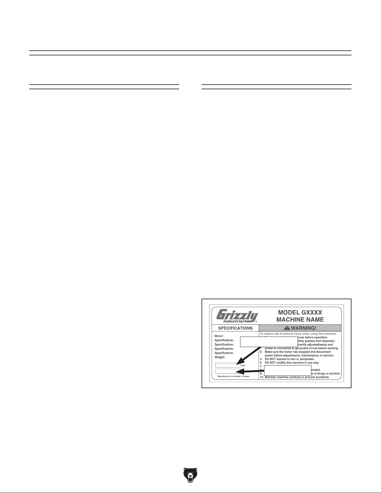
for help. Before calling, make sure you write down
the
from
the machine ID label (see below). This information
is required for us to provide proper tech support,
and it helps us determine if updated documentation is available for your machine.
We stand behind our machines! If you have questions or need help, contact us with the information
below. Before contacting, make sure you get the
serial number
machine ID label. This will help us help you faster.
We want your feedback on this manual. What did
you like about it? Where could it be improved?
Please take a few minutes to give us feedback.
Email: manuals@grizzly.com
Contact Info
and manufacture date from the
Grizzly Technical Support
1203 Lycoming Mall Circle
Muncy, PA 17756
Phone: (570) 546-9663
Email: techsupport@grizzly.com
Grizzly Documentation Manager
P.O. Box 2069
Bellingham, WA 98227-2069
Manual Accuracy
made every effort to be exact with the
sometimes the machine
.
,
e post
manual updates for free
www.grizzly.com.
Manufacture Date and Serial Number
Manufacture Date
Serial Number
-2-
Model G0790 (Mfd. Since 9/15)
Page 5
Identification
To reduce your risk of
serious injury, read this
entire manual BEFORE
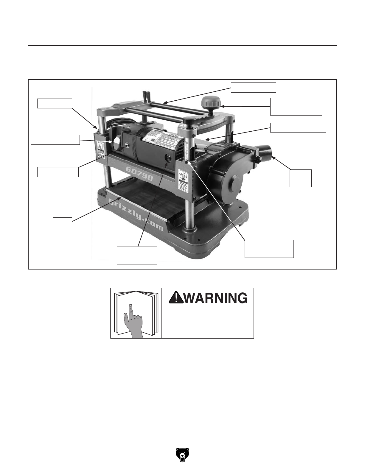
Become familiar with the names and locations of the controls and features shown below to better understand
the instructions in this manual.
Return Rollers
Cord Wrap
ON/OFF Switch
Reset Button
Table
Motor Brush
Housing
Model G0790 controls and components.
Cutterhead
Elevation Crank
Cutterhead Guard
Dust
Port
Cutterhead
Elevation Scale
Model G0790 (Mfd. Since 9/15)
using machine.
-3-
Page 6
Controls &
To reduce your risk of
serious injury, read this
entire manual BEFORE
Components
using machine.
DF
E
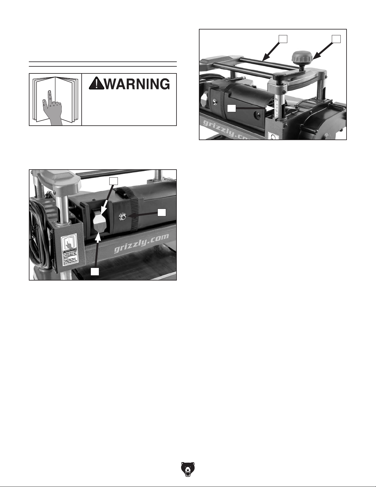
Refer to Figures 1–2 and the following descriptions to become familiar with the basic controls of
this machine.
B
C
A
Figure 1. ON/OFF switch and reset button.
A. ON/OFF Switch: Turns motor ON when
flipped up; turns motor OFF when pressed
down.
Figure 2. Elevation controls and return rollers.
D. Cutterhead Elevation Crank: Raises and
lowers cutterhead. Turning clockwise raises
cutterhead; turning counterclockwise lowers
it.
E. Cutterhead Elevation Scale: Shows the
elevation of the cutterhead above the table.
The measurement indicated by the red arrow
is the effective thickness of the board after
planing.
F. Return Rollers: For assistant to slide
workpiece back to operator following planing
operation.
B. ON/OFF Switch Disabling Key: Disables
switch when yellow key is removed so motor
cannot start.
C. Reset Button: Allows machine to be restart-
ed after thermal overload protection has
tripped the motor. To reset the button, place
ON/OFF switch in OFF position, wait a few
minutes for motor to cool, then press reset
button. If button does not stay depressed,
allow motor to cool off longer, then try again.
-4-
Model G0790 (Mfd. Since 9/15)
Page 7

MACHINE DATA
SHEET
Customer Service #: (570) 546-9663 · To Order Call: (800) 523-4777 · Fax #: (800) 438-5901
MODEL G0790 12‐1/2" BENCHTOP PLANER WITH DUST
COLLECTION
Product Dimensions:
Weight................................................................................................................................................................ 65 lbs.
Width (side-to-side) x Depth (front-to-back) x Height............................................................... 23-1/2 x 19 x 18-1/2 in.
Footprint (Length x Width)..................................................................................................................... 22-1/2 x 13 in.
Shipping Dimensions:
Type..................................................................................................................................................... Cardboard Box
Content........................................................................................................................................................... Machine
Weight................................................................................................................................................................ 72 lbs.
Length x Width x Height....................................................................................................................... 25 x 16 x 18 in.
Must Ship Upright................................................................................................................................................... Yes
Electrical:
Power Requirement........................................................................................................... 120V, Single-Phase, 60 Hz
Prewired Voltage.................................................................................................................................................. 120V
Full-Load Current Rating........................................................................................................................................ 15A
Minimum Circuit Size.............................................................................................................................................. 20A
Connection Type....................................................................................................................................... Cord & Plug
Power Cord Included.............................................................................................................................................. Yes
Power Cord Length................................................................................................................................................. 6 ft.
Power Cord Gauge......................................................................................................................................... 14 AWG
Plug Included.......................................................................................................................................................... Yes
Included Plug Type................................................................................................................................................ 5-15
Switch Type.................................................................................................. Paddle Switch w/Removable Safety Key
Motors:
Universal
Type......................................................................................................................... Universal Motor w/Brushes
Horsepower................................................................................................................................................ 2 HP
Phase............................................................................................................................................ Single-Phase
Amps............................................................................................................................................................ 15A
Speed............................................................................................................................................. 17,500 RPM
Power Transfer .................................................................................................................................. Belt Drive
Bearings.................................................................................................... Shielded & Permanently Lubricated
Main Specifications:
Main Specifications
Planer Size............................................................................................................................................. 12.5 in.
Max. Cut Width.................................................................................................................................... 12-1/2 in.
Min. Stock Thickness.............................................................................................................................. 5/16 in.
Max. Stock Thickness............................................................................................................................ 4-1/2 in.
Number of Cuts Per Inch................................................................................................................................ 60
Number of Cuts Per Minute..................................................................................................................... 17,500
Cutterhead Speed............................................................................................................................. 8750 RPM
Planing Feed Rate................................................................................................................................. 26 FPM
Max. Cut Depth Planing Full Width......................................................................................................... 1/32 in.
Model G0790 (Mfd. Since 9/15)
-5-
Page 8

Cutterhead Info
Cutterhead Type......................................................................................................................................
Cutterhead Diameter .................................................................................................................................. 2 in.
Number of Knives............................................................................................................................................. 2
Knife Type................................................................................................................................ HSS, Reversible
Knife Size Length................................................................................................................................ 12-1/2 in.
Knife Size Width....................................................................................................................................... 1/2 in.
Knife Size Thickness.............................................................................................................................. 1/16 in.
Table Info
Table Bed Size Length........................................................................................................................ 12-3/4 in.
Table Bed Size Width.......................................................................................................................... 12-1/2 in.
Table Bed Size Thickness..................................................................................................................... 3-5/8 in.
Construction
Table........................................................................................................................................... Stainless Steel
Body................................................................................................................................................... Aluminum
Cutterhead Assembly................................................................................................................................. Steel
Infeed Roller............................................................................................................................... Rubber & Steel
Outfeed Roller............................................................................................................................ Rubber & Steel
Paint Type/Finish....................................................................................................................... Powder Coated
Other
Measurement Scale....................................................................................................................... Inch & Metric
Number of Dust Ports....................................................................................................................................... 1
Dust Port Size........................................................................................................................................ 2-3/8 in.
2 Knife
Other Specifications:
Country of Origin ................................................................................................................................................ China
Warranty ........................................................................................................................................................... 1 Year
Serial Number Location ................................................................................................................................. ID Panel
Sound Rating ..................................................................................................................................................... 95 dB
ISO 9001 Factory .................................................................................................................................................. Yes
CSA, ETL, or UL Certified/Listed ................................................................................................................. Yes (ETL)
Features:
4-1/2" maximum cutting height
Magnetic handles for changing knives
Built-in cord wrap
12-1/2" x 12-3/4" table size
-6-
Model G0790 (Mfd. Since 9/15)
Page 9
SECTION 1: SAFETY
For Your Own Safety, Read Instruction
Manual Before Operating This Machine
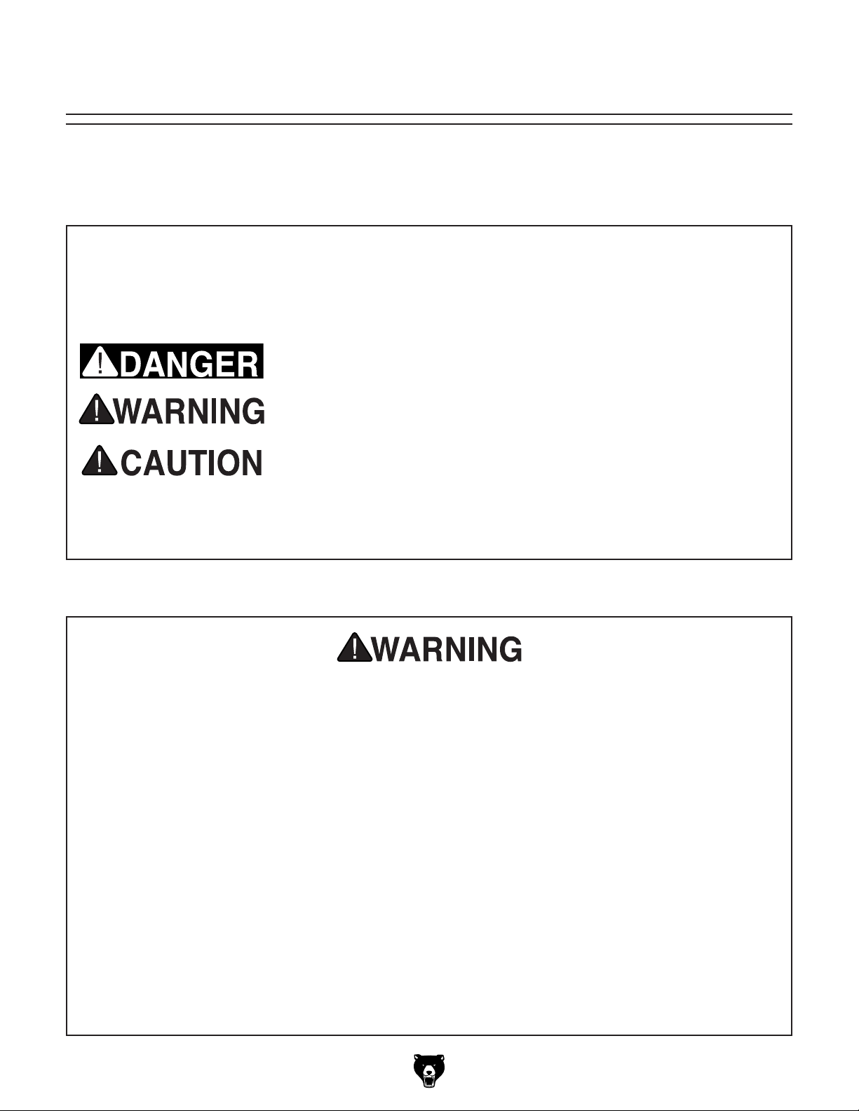
The purpose of safety symbols is to attract your attention to possible hazardous conditions.
This manual uses a series of symbols and signal words intended to convey the level of importance of the safety messages. The progression of symbols is described below. Remember that
safety messages by themselves do not eliminate danger and are not a substitute for proper
accident prevention measures. Always use common sense and good judgment.
Indicates an imminently hazardous situation which, if not avoided,
WILL result in death or serious injury.
Indicates a potentially hazardous situation which, if not avoided,
COULD result in death or serious injury.
Indicates a potentially hazardous situation which, if not avoided,
MAY result in minor or moderate injury. It may also be used to alert
against unsafe practices.
This symbol is used to alert the user to useful information about
NOTICE
proper operation of the machine.
Safety Instructions for Machinery
OWNER’S MANUAL. Read and understand this
owner’s manual BEFORE using machine.
TRAINED OPERATORS ONLY. Untrained operators have a higher risk of being hurt or killed.
Only allow trained/supervised people to use this
machine. When machine is not being used, disconnect power, remove switch keys, or lock-out
machine to prevent unauthorized use—especially
around children. Make workshop kid proof!
DANGEROUS ENVIRONMENTS. Do not use
machinery in areas that are wet, cluttered, or have
poor lighting. Operating machinery in these areas
greatly increases the risk of accidents and injury.
MENTAL ALERTNESS REQUIRED. Full mental
alertness is required for safe operation of machinery. Never operate under the influence of drugs or
alcohol, when tired, or when distracted.
ELECTRICAL EQUIPMENT INJURY RISKS. You
can be shocked, burned, or killed by touching live
electrical components or improperly grounded
machinery. To reduce this risk, only allow qualified
service personnel to do electrical installation or
repair work, and always disconnect power before
accessing or exposing electrical equipment.
DISCONNECT POWER FIRST.
nect machine from power supply BEFORE making
adjustments, changing tooling, or servicing machine.
This prevents an injury risk from unintended startup
or contact with live electrical components.
EYE PROTECTION. Always wear ANSI-approved
safety glasses or a face shield when operating or
observing machinery to reduce the risk of eye
injury or blindness from flying particles. Everyday
eyeglasses are NOT approved safety glasses.
Always discon-
Model G0790 (Mfd. Since 9/15)
-7-
Page 10

WEARING PROPER APPAREL. Do not wear
clothing, apparel or jewelry that can become
entangled in moving parts. Always tie back or
cover long hair. Wear non-slip footwear to reduce
risk of slipping and losing control or accidentally
contacting cutting tool or moving parts.
HAZARDOUS DUST. Dust created by machinery
operations may cause cancer, birth defects, or
long-term respiratory damage. Be aware of dust
hazards associated with each workpiece material. Always wear a NIOSH-approved respirator to
reduce your risk.
HEARING PROTECTION. Always wear hearing protection when operating or observing loud
machinery. Extended exposure to this noise
without hearing protection can cause permanent
hearing loss.
REMOVE ADJUSTING TOOLS. Tools left on
machinery can become dangerous projectiles
upon startup. Never leave chuck keys, wrenches,
or any other tools on machine. Always verify
removal before starting!
USE CORRECT TOOL FOR THE JOB. Only use
this tool for its intended purpose—do not force
it or an attachment to do a job for which it was
not designed. Never make unapproved modifications—modifying tool or using it differently than
intended may result in malfunction or mechanical
failure that can lead to personal injury or death!
AWKWARD POSITIONS. Keep proper footing
and balance at all times when operating machine.
Do not overreach! Avoid awkward hand positions
that make workpiece control difficult or increase
the risk of accidental injury.
CHILDREN & BYSTANDERS. Keep children and
bystanders at a safe distance from the work area.
Stop using machine if they become a distraction.
GUARDS & COVERS. Guards and covers reduce
accidental contact with moving parts or flying
debris. Make sure they are properly installed,
undamaged, and working correctly BEFORE
operating machine.
FORCING MACHINERY. Do not force machine.
It will do the job safer and better at the rate for
which it was designed.
NEVER STAND ON MACHINE. Serious injury
may occur if machine is tipped or if the cutting
tool is unintentionally contacted.
STABLE MACHINE. Unexpected movement during operation greatly increases risk of injury or
loss of control. Before starting, verify machine is
stable and mobile base (if used) is locked.
USE RECOMMENDED ACCESSORIES. Consult
this owner’s manual or the manufacturer for recommended accessories. Using improper accessories will increase the risk of serious injury.
UNATTENDED OPERATION. To reduce the
risk of accidental injury, turn machine OFF and
ensure all moving parts completely stop before
walking away. Never leave machine running
while unattended.
MAINTAIN WITH CARE. Follow all maintenance
instructions and lubrication schedules to keep
machine in good working condition. A machine
that is improperly maintained could malfunction,
leading to serious personal injury or death.
DAMAGED PARTS. Regularly inspect machine
for damaged, loose, or mis-adjusted parts—or
any condition that could affect safe operation.
Immediately repair/replace BEFORE operating
machine. For your own safety, DO NOT operate
machine with damaged parts!
MAINTAIN POWER CORDS. When disconnecting cord-connected machines from power, grab
and pull the plug—NOT the cord. Pulling the cord
may damage the wires inside. Do not handle
cord/plug with wet hands. Avoid cord damage by
keeping it away from heated surfaces, high traffic
areas, harsh chemicals, and wet/damp locations.
EXPERIENCING DIFFICULTIES. If at any time
you experience difficulties performing the intended operation, stop using the machine! Contact our
Technical Support at (570) 546-9663.
-8-
Model G0790 (Mfd. Since 9/15)
Page 11

Additional Safety for Planers
Wood chips fly
PLANER INJURY RISKS. Familiarize yourself
with the main injury risks associated with planers—always use common sense and good judgement to reduce your risk of injury. Main injury
risks from planers: amputation/lacerations from
contact with the moving cutterhead, entanglement/crushing injuries from getting caught in
moving parts, blindness or eye injury from flying
wood chips, or impact injuries from workpiece
kickback.
KICKBACK. Know how to reduce the risk of kickback and kickback-related injuries. “Kickback”
occurs during the operation when the workpiece is
ejected from the machine at a high rate of speed.
Kickback is commonly caused by poor workpiece
selection, unsafe feeding techniques, or improper
machine setup/maintenance. Kickback injuries
typically occur as follows: (1) operator/bystanders
are struck by the workpiece, resulting in impact
injuries (i.e., blindness, broken bones, bruises,
death); (2) operator’s hands are pulled into blade,
resulting in amputation or severe lacerations.
REACHING INSIDE PLANER. Never remove
guards/covers or reach inside the planer during
operation or while connected to power. You could
be seriously injured if you accidentally touch the
spinning cutterhead or get entangled in moving
parts. If a workpiece becomes stuck or sawdust
removal is necessary, turn planer OFF and disconnect power before clearing.
DULL/DAMAGED KNIVES/INSERTS. Only use
sharp, undamaged knives/inserts. Dull or damaged knives/inserts increase the risk of kickback.
INSPECTING STOCK. To reduce the risk of
kickback injuries or machine damage, thoroughly
inspect and prepare the workpiece before cutting.
Verify workpiece is free of nails, staples, loose
knots or foreign material. Workpieces with minor
warping should be jointed first or planed with the
cupped side facing the infeed table.
GRAIN DIRECTION. Planing across the grain
is hard on the planer and may cause kickback.
Plane in the same direction or at a slight angle
with the wood grain.
PLANING CORRECT MATERIAL. Only plane
natural wood stock with this planer. DO NOT
plane MDF, OSB, plywood, laminates or other
synthetic materials that can break up inside the
planer and be ejected towards the operator.
LOOKING INSIDE PLANER.
around inside the planer at a high rate of speed
during operation. To avoid injury from flying material, DO NOT look inside planer during operation.
CUTTING LIMITATIONS. To reduce the risk of
kickback hazards or damage to the machine, do
not exceed the maximum depth of cut or minimum
board length and thickness found in the Data
Sheet. Only feed one board at a time.
INFEED ROLLER CLEARANCE. The infeed
roller is designed to pull material into the spinning
cutterhead. To reduce the risk of entanglement,
keep hands, clothing, jewelry, and long hair away
from the infeed roller during operation.
FEED WORKPIECE PROPERLY. To reduce the
risk of kickback, never start planer with workpiece
touching cutterhead. Allow cutterhead to reach
full speed before feeding, and do not change feed
speed during cutting operation.
WORKPIECE SUPPORT. To reduce the risk of
kickback, always make sure workpiece can move
completely across table without rocking or tipping.
Use auxiliary support stands for long stock.
SECURE KNIVES/INSERTS. Loose knives or
improperly set inserts can become dangerous
projectiles or cause machine damage. Always
verify knives/inserts are secure and properly
adjusted before operation.
BODY PLACEMENT. Stand to one side of planer
during the entire operation to avoid getting hit if
kickback occurs.
Model G0790 (Mfd. Since 9/15)
-9-
Page 12
SECTION 2: POWER SUPPLY
Before installing the machine, consider the availability and proximity of the required power supply
circuit. If an existing circuit does not meet the
requirements for this machine, a new circuit must
be installed. To minimize the risk of electrocution,
fire, or equipment damage, installation work and
electrical wiring must be done by an electrician or
qualified service personnel in accordance with all
applicable codes and standards.
Electrocution, fire, or
equipment damage may
occur if machine is not
correctly grounded and
The full-load current rating is the amperage a
machine draws at 100% of the rated output power.
On machines with multiple motors, this is the
amperage drawn by the largest motor or sum of all
motors and electrical devices that might operate
at one time during normal operations.
The full-load current is not the maximum amount
of amps that the machine will draw. If the machine
is overloaded, it will draw additional amps beyond
the full-load rating.
If the machine is overloaded for a sufficient length
of time, damage, overheating, or fire may result—
especially if connected to an undersized circuit.
To reduce the risk of these hazards, avoid overloading the machine during operation and make
sure it is connected to a power supply circuit that
meets the specified circuit requirements.
For your own safety and protection of
Note: Circuit requirements in this manual apply to
a dedicated circuit—where only one machine will
be running on the circuit at a time. If machine will
be connected to a shared circuit where multiple
machines may be running at the same time, consult an electrician or qualified service personnel to
ensure circuit is properly sized for safe operation.
A power supply circuit includes all electrical
equipment between the breaker box or fuse panel
in the building and the machine. The power supply circuit used for this machine must be sized to
safely handle the full-load current drawn from the
machine for an extended period of time. (If this
machine is connected to a circuit protected by
fuses, use a time delay fuse marked D.)
This machine is prewired to operate on a power
supply circuit that has a verified ground and meets
the following requirements:
Availability
Serious injury could occur if you connect
machine to power before completing setup
process. DO NOT connect to power until
instructed later in this manual.
Circuit Requirements
Nominal Voltage .................... 110V, 115 V, 120V
Cycle .......................................................... 60 Hz
Phase ........................................... Single-Phase
Power Supply Circuit ......................... 20 Amps
connected to the power
supply.
Full-Load Current Rating
Full-Load Current Rating at 120V ..... 15 Amps
-10 -
property, consult an electrician if you are
unsure about wiring practices or electrical
codes in your area.
Model G0790 (Mfd. Since 9/15)
Page 13
Improper connection of the equipment-grounding
wire can result in a risk of electric shock. The
wire with green insulation (with or without yellow
stripes) is the equipment-grounding wire. If repair
or replacement of the power cord or plug is necessary, do not connect the equipment-grounding
wire to a live (current carrying) terminal.
Check with a qualified electrician or service personnel if you do not understand these grounding
requirements, or if you are in doubt about whether
the tool is properly grounded. If you ever notice
that a cord or plug is damaged or worn, disconnect it from power, and immediately replace it with
a new one.
We do not recommend using an extension cord
with this machine.
cord, only use it if absolutely necessary and only
on a temporary basis.
Extension cords cause voltage drop, which can
damage electrical components and shorten motor
life. Voltage drop increases as the extension cord
size gets longer and the gauge size gets smaller
(higher gauge numbers indicate smaller sizes).
Any extension cord used with this machine must
be in good condition and contain a ground wire
and matching plug/receptacle. Additionally, it must
meet the following size requirements:
Grounding & Plug Requirements
it will not fit the outlet, have a qualified
This machine MUST be grounded. In the event
of certain malfunctions or breakdowns, grounding
reduces the risk of electric shock by providing a
path of least resistance for electric current.
This machine is equipped with a power cord that
has an equipment-grounding wire and a grounding
plug. Only insert plug into a matching receptacle
(outlet) that is properly installed and grounded in
accordance with all local codes and ordinances.
DO NOT modify the provided plug!
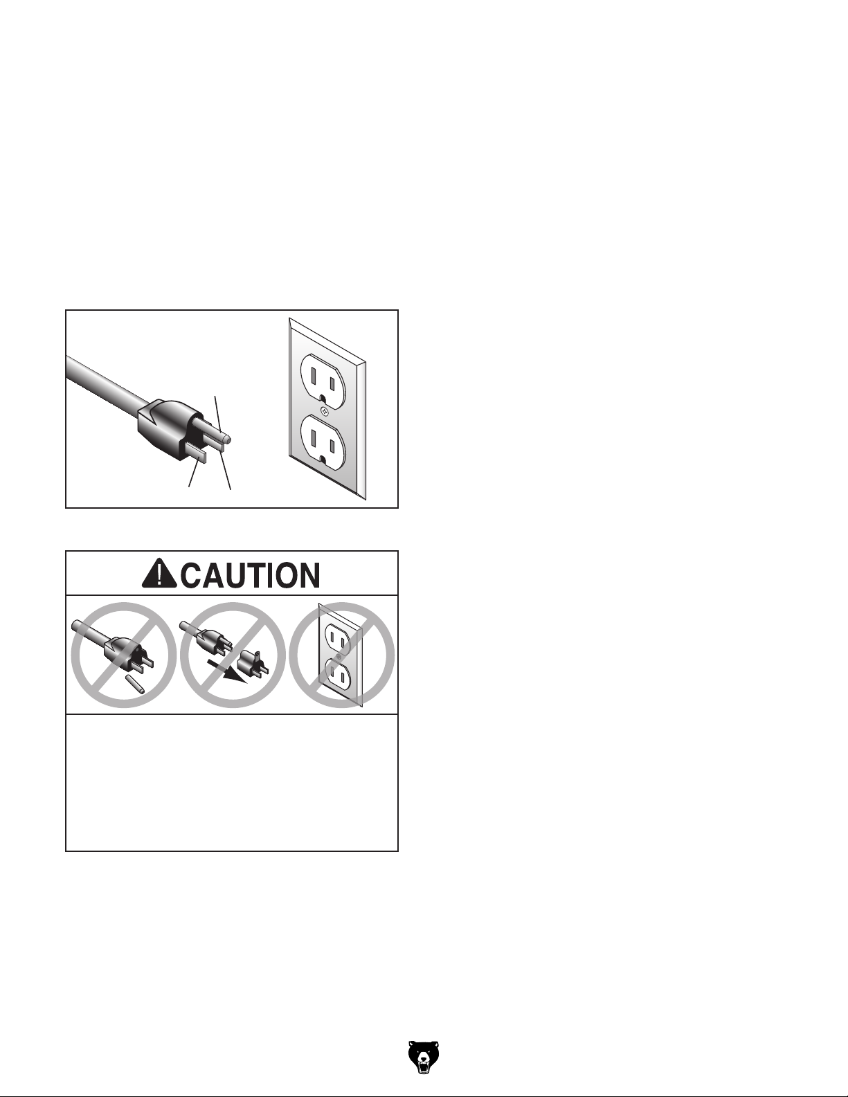
GROUNDED
5-15 RECEPTACLE
Grounding Prong
5-15 PLUG
Extension Cords
If you must use an extension
Neutral Hot
Figure 3. Typical 5-15 plug and receptacle.
SHOCK HAZARD!
Two-prong outlets do not meet the grounding
requirements for this machine. Do not modify
or use an adapter on the plug provided—if
electrician install the proper outlet with a
verified ground.
Model G0790 (Mfd. Since 9/15)
Minimum Gauge Size ...........................12 AWG
Maximum Length (Shorter is Better).......50 ft.
-11-
Page 14
SECTION 3: SETUP
Your machine was carefully packaged for safe
transportation. Remove the packaging materials
from around your machine and inspect it. If you
discover any damage, please call us immediately
at (570) 546-9663
Save the containers and all packing materials for
possible inspection by the carrier or its agent.
Otherwise, filing a freight claim can be difficult.
When you are completely satisfied with the condition of your shipment, inventory the contents.
Keep children and pets away
from plastic bags or packing
materials shipped with this
The following is a list of items shipped with your
machine. Before beginning setup, lay these items
out and inventory them.
If any non-proprietary parts are missing (e.g. a
nut or a washer), we will gladly replace them; or
for the sake of expediency, replacements can be
obtained at your local hardware store.
Unpacking
for advice.
SUFFOCATION HAZARD!
machine. Discard immediately.
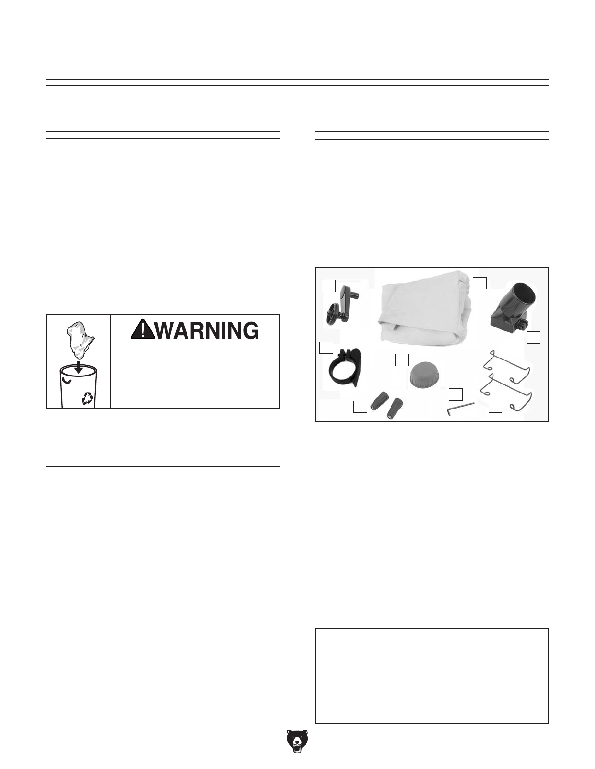
Inventory
A
H
F
G
B
C
E
D
Needed for Setup
The following are needed to complete the setup
process, but are not included with your machine.
Description Qty
• Safety Glasses ........................................... 1
• Cleaner/Degreaser ..................... As Needed
• Disposable Shop Rags ............... As Needed
• Screwdriver Phillips #2 ............................... 1
• Dust Collection System .............................. 1
-12-
Figure 4. Model G0790 inventory.
Box 1 (Figure 4) Qty
A. Cutterhead Elevation Crank ....................... 1
B. Dust Bag ..................................................... 1
C. Dust Port 2
D. Cord Wraps ................................................ 2
E. Hex Wrench 4mm ....................................... 1
F. Cutterhead Elevation Crank Knob .............. 1
G. Knife Changing Magnets ............................ 2
H. Dust Bag Clamp ......................................... 1
I. Hardware (not shown) ................................ 1
—M4-.7 x 10 Phillips Head Screws ............ 4
—M5-.8 x 25 Button Head Cap Screw ....... 1
—Flat Washer 5mm ................................... 1
3
⁄8" ............................................ 1
NOTICE
If you cannot find an item on this list, carefully check around/inside the machine and
packaging materials. Often, these items get
lost in packaging materials while unpacking or they are pre-installed at the factory.
Model G0790 (Mfd. Since 9/15)
Page 15
Cleanup Site Considerations
The unpainted surfaces of your machine are
coated with a heavy-duty rust preventative that
prevents corrosion during shipment and storage.
This rust preventative works extremely well, but it
will take a little time to clean.
Be patient and do a thorough job cleaning your
machine. The time you spend doing this now will
give you a better appreciation for the proper care
of your machine's unpainted surfaces.
There are many ways to remove this rust preventative, but the following steps work well in a wide
variety of situations. Always follow the manufacturer’s instructions with any cleaning product you
use and make sure you work in a well-ventilated
area to minimize exposure to toxic fumes.
Before cleaning, gather the following:
• Disposable rags
• Cleaner/degreaser (WD•40 works well)
• Safety glasses & disposable gloves
• Plastic paint scraper (optional)
Basic steps for removing rust preventative:
1.
2.
amount of cleaner/degreaser, then let it soak
3.
scrape off as much as you can first, then wipe
4.
then coat all unpainted surfaces with a quality
Avoid chlorine-based solvents, such as
or disable start switch or
Refer to the Machine Data Sheet for the weight
and footprint specifications of your machine.
Some workbenches may require additional reinforcement to support the weight of the machine
and workpiece materials.
Consider anticipated workpiece sizes and additional space needed for auxiliary stands, work
tables, or other machinery when establishing a
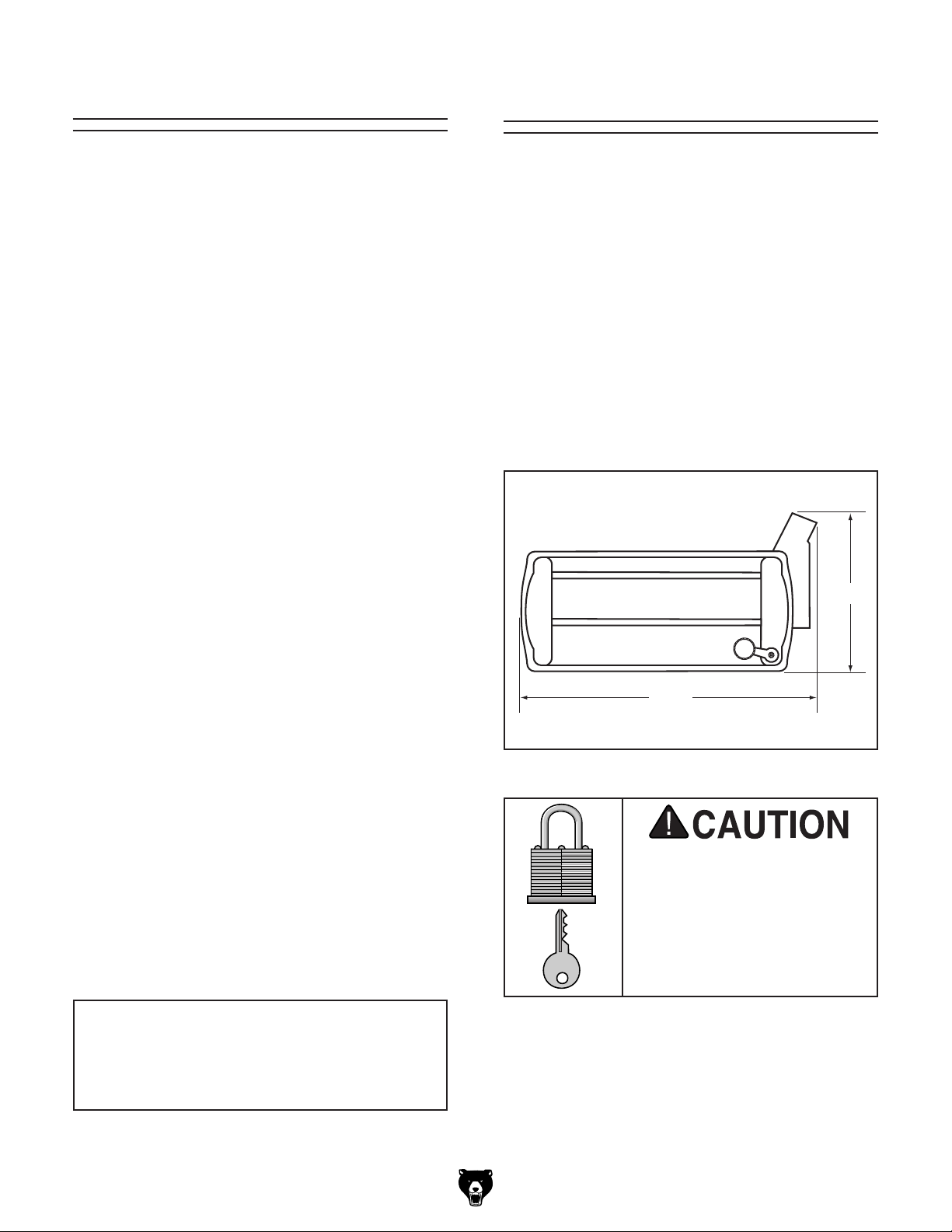
location for this machine in the shop. Below is
the minimum amount of space needed for the
machine.
Workbench Load
Placement Location
17"
Put on safety glasses.
Coat the rust preventative with a liberal
for 5–10 minutes.
Wipe off the surfaces. If your cleaner/degreas-
er is effective, the rust preventative will wipe
off easily. If you have a plastic paint scraper,
off the rest with the rag.
Repeat Steps 2–3 as necessary until clean,
metal protectant to prevent rust.
NOTICE
acetone or brake parts cleaner, that may
damage painted surfaces.
231/2"
Figure 5. Minimum working clearances.
Children and visitors may be
seriously injured if unsupervised around this machine.
Lock entrances to the shop
power connection to prevent
unsupervised use.
Model G0790 (Mfd. Since 9/15)
-13-
Page 16

Bench Mounting
Another option is a "Direct Mount" (see example
below) where the machine is secured directly to
the workbench with lag screws and washers.
The base of this machine has mounting holes
that allow it to be fastened to a workbench or
other mounting surface to prevent it from moving
during operation and causing accidental injury or
damage.
The strongest mounting option is a "Through
Mount" (see example below) where holes are
drilled all the way through the workbench—and
hex bolts, washers, and hex nuts are used to
secure the machine in place.
Assembly
Number of Mounting Holes ............................ 4
Dia. of Mounting Hardware Needed ..........
Hex
Bolt
Flat Washer
Machine Base
5
⁄16"
The cutterhead elevation crank, cord wraps, and
dust port must be installed in order to operate the
planer.
To assemble planer loose parts:
1. Assemble cutterhead elevation crank by
snapping knob onto crank handle.
2. Remove black plastic lid from crank handle.
3. Align flat portion inside crank handle bore
with flat portion on elevation shaft, then place
crank assembly on elevation shaft.
4. Thread M5-.8 x 25 button head cap screw
and 5mm flat washer through crank (see
Figure 8) and into shaft. Tighten with 4mm
hex wrench. Do not over-tighten.
Workbench
Flat Washer
Lock Washer
Figure 6. Typical "Through Mount" setup.
Machine Base
Hex Nut
Lag Screw
Flat Washer
Cutterhead
Elevation Crank
Figure 8. Installing cutterhead elevation crank.
5. Re-install black plastic lid.
Workbench
Figure 7. Typical "Direct Mount" setup.
-14-
Model G0790 (Mfd. Since 9/15)
Page 17

6. Position (2) cord wraps over pre-drilled holes
in planer cabinet (see Figure 9), and secure
with (4) M4-.7 x 10 Phillips head screws.
x 4
Figure 9. Cord wraps installed with #2 Phillips
head screwdriver.
7. Slide dust port onto fan housing (see Figure
10) and tighten pre-installed button head cap
screw with 4mm hex wrench.
Dust Port
Dust Collection
This machine creates substantial amounts
of dust during operation. Breathing airborne dust on a regular basis can result in
permanent respiratory illness. Reduce your
risk by wearing a respirator and capturing
the dust with a dust collection system.
Recommended CFM at Dust Port: 250 CFM
Do not confuse this CFM recommendation with
the rating of the dust collector. To determine the
CFM at the dust port, you must consider these
variables: (1) CFM rating of the dust collector,
(2) hose type and length between the dust collector and the machine, (3) number of branches
or wyes, and (4) amount of other open lines
throughout the system. Explaining how to calculate these variables is beyond the scope of
this manual. Consult an expert or purchase a
good dust collection "how-to" book.
Fan
Housing
Figure 10. Dust port installed on fan housing.
8. Slide dust hose clamp over dust bag, insert
bag and clamp over dust port (see Figure
11), and secure with handle.
Dust Port
Dust Bag
Clamp
To connect a dust collection hose:
1. If installed, remove dust bag and clamp from
dust port (see Figure 11).
1
2. Fit 2
3. Tug hose to make sure it does not come
⁄2" dust hose over dust port and secure
with hose clamp.
off. Note: A tight fit is necessary for proper
performance.
Figure 11. Dust bag installed on port and
secured by clamp.
Model G0790 (Mfd. Since 9/15)
-15-
Page 18

Test Run
Once assembly is complete, test run the machine
to ensure it is properly connected to power and
safety components are functioning properly.
If you find an unusual problem during the test run,
immediately stop the machine, disconnect it from
power, and fix the problem BEFORE operating the
machine again. The
table in the
SERVICE section of this manual can help.
DO NOT start machine until all preceding
setup instructions have been performed.
Operating an improperly set up machine
ed results that can lead to serious injury,
Serious injury or death can result from
To test run machine:
1. Make sure you have read safety instructions
at beginning of manual and that machine is
set up properly.
2. Make sure all tools and objects used during
setup are cleared away from machine.
3. Connect machine to power source.
Troubleshooting
The test run consists of verifying the following:
1) The motor powers up and runs correctly, and
2) the safety disabling mechanism on the switch
works correctly.
using this machine BEFORE understanding
its controls and related safety information.
DO NOT operate, or allow others to operate,
machine until the information is understood.
may result in malfunction or unexpect-
death, or machine/property damage.
4. Turn machine ON, verify motor operation,
then turn machine OFF. Motor should run
smoothly and without unusual problems or
noises.
5. Remove switch disabling key, as shown in
Figure 12.
Figure 12. Removing key from paddle switch to
disable switch and prevent unauthorized use.
6. Try to start machine with paddle switch.
— If machine does not start, switch disabling
feature is working as designed.
-16-
— If machine starts, immediately stop
machine. The switch disabling feature is
not working correctly. This safety feature
must work properly before proceeding with
regular operations. Call Tech Support for
help.
Model G0790 (Mfd. Since 9/15)
Page 19

SECTION 4: OPERATIONS
The purpose of this overview is to provide the novice machine operator with a basic understanding
of how the machine is used during operation, so
the
discussed later
in this manual
Due to the generic nature of this overview, it is
not intended to be an instructional guide. To learn
more about specific operations, read this entire
manual and
rienced
research outside of this manual by reading "howto" books, trade magazines, or websites.
To reduce your risk of
serious injury, read this
entire manual BEFORE
Operation Overview
machine controls/components
are easier to understand.
seek additional training from expe-
machine operators, and do additional
To complete a typical operation, the operator
does the following:
1. Examines workpiece to make sure it is suit-
able for planing.
2. Puts on safety glasses or face shield, a respirator, and ear protection.
3. If workpiece is bowed, operator surface
planes workpiece on a jointer until one side
is flat. Doing so ensures that it sits solidly on
planer table during operation.
4. Places workpiece on table with flat side
down. Positions front edge of workpiece far
enough under cutterhead assembly to set
depth of cut using cutterhead elevation scale
(see Depth of Cut on Page 20).
using machine.
Eye injuries, respiratory problems, or hearing loss can occur while operating this
tool. Wear personal protective equipment to
reduce your risk from these hazards.
If you are not experienced with this type
of machine, WE STRONGLY RECOMMEND
that you seek additional training outside of
this manual. Read books/magazines or get
formal training before beginning any projects. Regardless of the content in this section, Grizzly Industrial will not be held liable
for accidents caused by lack of training.
Model G0790 (Mfd. Since 9/15)
5. Correctly adjusts cutterhead height to
workpiece thickness.
6. When all safety precautions have been taken,
turns planer ON.
7. Stands to one side of planer path to reduce
risk of kickback injuries, then, with flat surface
of workpiece facing down, feeds workpiece
into planer until infeed roller grabs it.
8. Once workpiece is clear of outfeed roller,
operator measures workpiece thickness. If
further planing is required, operator adjusts
cutterhead height, then feed workpiece into
front of planer again.
9. Operator continues process until desired
thickness is achieved, then turns machine
OFF.
-17-
Page 20

Workpiece Inspection
Some workpieces are not safe to use or may
require modification before they are. Before cut-
ting, inspect all workpieces for the following:
• Material Type: This machine is only intended for workpieces of natural wood fiber
Attempting to use workpieces of any other
material that may break apart during operation could lead to serious personal injury and
property damage.
• Foreign Objects: Inspect lumber for defects
and foreign objects (nails, staples, imbedded
gravel, etc,). If you have any question about
the quality of your lumber, DO NOT use it.
Remember, wood stacked on a concrete floor
can have small pieces of stone or concrete
pressed into the surface.
• Large/Loose Knots: Loose knots can
become dislodged during operation. Large
knots can cause kickback and machine damage. Always use workpieces that do not have
large/loose knots.
• Wet or "Green" Stock: Avoid using wood
with a high water content. Wood with more
than 20% moisture content or wood exposed
to excessive moisture (such as rain or snow),
will cut poorly and cause excessive wear to
the machine. Excess moisture can also hasten rust and corrosion of the machine and/or
individual components.
• Excessive Warping: Workpieces with excessive cupping, bowing, or twisting are dangerous to cut because they are unstable and
often unpredictable when being cut. DO NOT
use workpieces with these characteristics!
• Minor Cupping: Workpieces with slight cupping can be safely supported if the cupped
side is facing the table. On the contrary,
a workpiece supported on the bowed side
will rock during operation and could cause
severe injury from kickback.
Wood Types
The species of wood, as well as its condition,
greatly affects the depth of cut the planer can
effectively take with each pass.
The chart in the figure below shows the Janka
Hardness Rating for a number of commonly
used species. The larger the number, the harder
the workpiece, and the less material should be
removed in any one pass for good results.
Note: The Janka Hardness Rating is expressed in
pounds of force required to embed a 0.444" steel
ball into the surface of the wood to a depth equal
to half the ball's diameter.
Janka
Species
Ebony 3220
Red Mahogany 2697
Rosewood 178 0
Red Pine 1630
Sugar Maple 1450
White Oak 1360
White Ash 1320
American Beech 1300
Red Oak 1290
Black Walnut 1010
Teak 1000
Black Cherry 950
Cedar 900
Sycamore 770
Douglas Fir 660
Chestnut 540
Hemlock 500
White Pin 420
Basswood 410
Eastern White Pine 380
Balsa 100
Figure 13. Janka Hardness Rating for some
common wood species.
Hardness
-18-
Model G0790 (Mfd. Since 9/15)
Page 21

Planing Tips
Cutting Problems
• Inspect your lumber for twisting or cupping,
and surface one face on a jointer if necessary
before planing workpiece.
• Scrape off all glue when planing glued-up
panels. Dried glue can quickly dull knives.
• DO NOT plane more than one piece at a
time.
• Never remove more than the recommended
amount of material on each pass. Only
remove a small amount of material on each
pass when planing wide or dense stock.
• Support the workpiece on both ends. Get
assistance from another person if you are
planing long lumber, or use roller stands to
support the workpiece.
• Measure the workpiece thickness with cali-
pers to get exact results.
• Carefully inspect all stock to make sure it is
free of large knots or foreign objects that may
damage your knives, cause kickback, or be
ejected from the planer.
• When possible, plane equal amounts on
each side of the board to reduce the chance
of twisting or cupping.
• Use the entire width of the planer to wear
knives evenly. With narrow workpieces, alternate between far left, far right, and the middle
of the table. Your knives will remain sharp
much longer.
• To avoid "chip marks," always plane WITH
the grain direction of the wood. Never plain
cross-grain or end-grain.
• Plane ONLY natural wood fiber. Do not
plane wood composites or other materials
that could break up in the planer and cause
operator injury or damage to planer.
Below is a list of wood characteristics you may
encounter when planing. The following descriptions of defects will give you some possible
answers to problems you may encounter while
planing different materials. Possible solutions follow the descriptions.
Chipped Grain
Problem: Usually a result of cutting against the
grain, planing lumber with knots or excessive
amount of cross grain, or using dull knives.
Solution: Decrease the depth of cut. Inspect
your lumber and determine if its grain pattern is
causing the problem. If the lumber does not show
substantial crossgrain, inspect your knives.
Fuzzy Grain
Problem: Usually caused by surfacing lumber
with too high of a moisture content. Sometimes
fuzzy grain is an unavoidable characteristic of
some woods, such as basswood. Fuzzy grain can
also be caused by dull knives.
Solution: Check the lumber with a moisture
meter. If moisture is greater than 20%, sticker the
lumber and allow it to dry. Otherwise, inspect the
knife condition.
Snipe
Problem: Occurs when board ends have more
material removed than the rest of the board.
Usually caused when the workpiece is not properly supported as it goes through the machine. In
many cases, however, a small amount of snipe is
inevitable.
Solution: The best way to deal with snipe is by
planing lumber longer than your intended work
length and then cutting off the excess after planing is completed.
• Always true cupped or warped stock on a
jointer before planing.
Model G0790 (Mfd. Since 9/15)
-19-
Page 22

Pitch & Glue Build-up
Problem: Glue and resin buildup on the rollers
and cutterhead will cause overheating by decreasing cutting sharpness while increasing drag in the
feed mechanism. The result can include scorched
lumber as well as uneven knife marks and chatter.
Solution: Clean the rollers and cutterhead.
Depth of Cut
The planing depth on the Model G0790 is controlled by the cutterhead elevation crank on top of
the planer. Turning the crank clockwise raises the
cutterhead; turning it counterclockwise lowers the
cutterhead.
Chip Marks or Indentations
Problem: Chip indentation or chip bruising is the
result of wood chips not being thrown away from
the cutterhead and out of the machine. Instead
they are carried around the cutterhead, deposited
on the planed surface and crushed by the outfeed
roller. Chip indentations can be caused by a number of reasons, some of which are:
• The type of lumber being planed. Certain
species have a tendency to chip bruise.
• A high moisture content (over 20%) or sur-
face moisture. Typically found in air-dried
stock where the surface is dry but the inside
needs a longer time to season.
• Dull knives.
• Too much material being removed in one
pass.
Solution:
Elevation Crank
The elevation crank provides a simple and accurate method for producing cuts of consistent
depth on multiple passes.
The pitch of the elevation leadscrew is 16 TPI
(threads per inch), meaning that every turn of the
crank will move the cutterhead
a base, you can make passes with a depth of cut
1
⁄64", 1⁄32", 3⁄64" and 1⁄16" by turning the crank 1⁄4
of
1
⁄2 turn, 3⁄4 turn, and one full turn, respectively
turn,
(see Figure 14).
3
⁄4 Turn
=3⁄64"
1
⁄16". Using this as
1
⁄2 Turn
=1⁄32"
DownUp
1
⁄4 Turn
=1⁄64"
• Lumber must be completely dry, preferably
kiln-dried (KD). Air-dried (AD) lumber must
be seasoned properly and have no surface
moisture. DO NOT surface partially-air-dried
(PAD) lumber.
• Make sure planer knives are sharp.
• Reduce depth of cut.
-20-
1 Turn
1
⁄16"
=
Figure 14. Crank elevation increments.
Note: Any time you switch directions with the
cutterhead elevation crank, there will be a small
amount of backlash—so the first turn of the crank
after switching directions will be slightly less than
1
⁄16". However, as long as you move the crank in
the same direction during the operation, backlash
will not be a factor.
Although the correct depth of cut varies according
to wood hardness and workpiece width, we recommend a maximum depth of cut no more than
1
⁄32". A series of light cuts will give better results
and put less stress on the planer than trying to
take off too much material in a single pass.
Model G0790 (Mfd. Since 9/15)
Page 23

Elevation Scale
The depth of cut is read directly from the elevation
scale (see Figure 15) on the righthand column at
the front of the machine. The measurement indicated by the red arrow is the effective thickness
of the board after planing.
Feeding Workpiece
The feed rate on this planer is automatically set
at 26 FPM. Infeed and outfeed rollers move the
workpiece through the planer while keeping it flat
and providing a consistent rate of movement.
Column
Scale
Red Arrow
Figure 15. Positioning elevation scale.
Example: If you need to plane a board down to
1", simply make multiple passes (no greater than
the maximum depth of cut) until the cutterhead
elevation scale reads 1". A final pass at this setting will create a 1" thick workpiece.
Note: The cutterhead elevation scale does not
provide a precise measurement and should only
be used for approximate measurements. If precise workpiece thicknesses are needed, use
calipers to ensure your workpieces meet your
standards.
To feed workpiece into planer:
1. Place workpiece on table so it is perpendicu-
lar to cutterhead, with side to be planed facing up toward cutterhead.
Note: Boards more than 24" long should be
supported on both sides of planer.
2. Lower cutterhead until depth bar (see Figure
16) just touches workpiece.
Outfeed
Depth
Bar
Infeed
Figure 16. Basic planing operation setup.
Model G0790 (Mfd. Since 9/15)
-21-
Page 24

Note: Any time you switch directions with
cutterhead elevation handle, there will be
a small amount of backlash—so first crank
of handle after switching directions will be
1
slightly less than
⁄16". However, as long as
you move handle in same direction during
operation, backlash will not be a factor.
3. Turn cutterhead elevation crank ¼ turn clock-
1
wise to raise cutterhead approximately
1
This will set depth of cut to
⁄32". Remove
⁄64".
workpiece from planer.
4. Turn planer ON.
5. With flat side of board facing down on table,
feed workpiece into front of planer, making
sure not to stand directly in front or behind
workpiece to reduce the risk of a kickback
injury.
— If cut is too deep and bogs down planer,
turn planer OFF immediately, allow it to
come to a complete stop, raise cutterhead,
remove workpiece, reduce depth of cut,
then repeat Step 5.
6. Once workpiece is clear of outfeed roller,
measure workpiece thickness. If further planing is needed, lower cutterhead by turning
1
elevation crank handle ½ turn (
⁄32"), return
the workpiece to the infeed table, then continue.
7. Continue this process until desired thickness is reached. Depth of cut indicator scale
shows approximate thickness of workpiece
after it has been cut. Use this indicator to
judge when thickness is approximately correct. For more precise applications, use a
caliper to measure workpiece thickness.
Note: Infeed and outfeed rollers will control
feed rate of workpiece as it passes through
planer. Do not push or pull on workpiece.
-22-
Model G0790 (Mfd. Since 9/15)
Page 25

SECTION 5: ACCESSORIES
Installing unapproved accessories may
order online at www.grizzly.com or call 1-800-523-4777
cause machine to malfunction, resulting in
serious personal injury or machine damage.
To reduce this risk, only install accessories
recommended for this machine by Grizzly.
H4978—Deluxe Earmuffs - 27dB
H4979—Twin Cup Hearing Protector - 29dB
T20446— Classic Earplugs, 200 pair - 31dB
Protect yourself comfortably with a pair of cushioned earmuffs. Especially important if you or
employees operate for hours at a time.
H4978
NOTICE
Refer to our website or latest catalog for
additional recommended accessories.
Basic Eye Protection
T20501—Face Shield Crown Protector 4"
T20502—Face Shield Crown Protector 7"
T20503—Face Shield Window
T20451—“Kirova” Clear Safety Glasses
T20452—“Kirova” Anti-Reflective S. Glasses
H7194—Bifocal Safety Glasses 1.5
H7195—Bifocal Safety Glasses 2.0
H7196—Bifocal Safety Glasses 2.5
T20502
T20452
T20503
T20446
H4979
Figure 18. Our most popular earmuffs.
H2499—Small Half-Mask Respirator
H3631—Medium Half-Mask Respirator
H3632—Large Half-Mask Respirator
H3635—Cartridge Filter Pair P100
Wood dust has been linked to nasal cancer and
severe respiratory illnesses. If you work arounddust everyday, a half-mask respirator can be a
lifesaver. Also compatible with safety glasses!
H7194
Figure 17. Assortment of basic eye protection.
Model G0790 (Mfd. Since 9/15)
T20451
Figure 19. Half-mask respirator with disposable
cartridge filters.
-23-
Page 26

T26979—3-in-1 Workpiece Support Stand
order online at www.grizzly.com or call 1-800-523-4777
This 3-in-1 Workpiece Support Stand features a
rotating head with steel roller topped with 8 rolling balls. The heavy-duty steel frame has four
outrigger legs for stability and an adjustable foot
1
for uneven floors. Height adjusts from 27
⁄2" to
43" and supports up to 250 lb. It even folds up for
easy storage!
Basic Lubricants
These lubricants reduce sliding friction and hangups, repel moisture and dirt, and inhibits rust while
preventing resin build-up. They out-performspaste
wax and contain no silicone or CFC's.
Figure 22. Model G5563 Slip-It Tool Lube &
G4682 Dry Coating Lube.
Figure 20. Model T26979 3-in-1 Workpiece
Support Stand.
G2857—Thickness Guage
Measure thicknesses and diameters quickly with
this handy gauge. Wonderful for thickness planers, wood lathes, and other shop measurements.
1
Measures from
⁄16" to 2" in 1⁄32" increments. Made
in the U.S.A.
G0725—6" x 28" Benchtop Jointer
Don’t let the size of this benchtop jointer fool you!
With its cast iron tables and center-mounted cast
iron fence, this 6" Jointer is tough enough to han-
1
dle big jobs. It also features a 1
⁄2 HP motor, 2 1⁄2"
dust port, built-in dust collection system, 45° bevel
adjustment, and easy-to-adjust knives. Great for
job sites or shops with limited space!
Figure 23. Model G0725 Benchtop Jointer.
Figure 21. Model G2857 Thickness Gauge.
-24-
Model G0790 (Mfd. Since 9/15)
Page 27

SECTION 6: MAINTENANCE
accidental startup, always
disconnect machine from
To reduce risk of shock or
power before adjustments,
maintenance, or service.
Schedule
For optimum performance from your machine,
follow this maintenance schedule and refer to any
specific instructions given in this section.
Lubrication
There are three primary systems that require
periodic lubrication: the cutterhead elevation leadscrews, the feed roller chain drive, and the table
height chain. Clean the components in the section
with an oil/grease solvent cleaner or mineral spirits before applying lubrication.
Elevation Leadscrews
Items Needed Qty
Type ............................. G4682 Dry Coating Lube
Lubrication Frequency .............................Monthly
Daily Check
• Loose mounting bolts.
• Damaged knives.
• Worn or damaged wires.
• Any other unsafe condition.
Monthly Check
• Clean chains and sprockets of dust, wood
chips, and old grease.
• Lightly coat chains and sprockets with automotive bearing grease (see Page 25).
• Lubricate column leadscrews with spray lubricant (see Page 24).
• Check V-belt for tension, damage, or wear
(see Page 29).
• Remove cutterhead guard and fan cover (see
Page 27), and thoroughly clean built-up sawdust and chips.
Cleaning &
To lubricate elevation leadscrews:
1. DISCONNECT MACHINE FROM POWER!
2. Vacuum chips and dust from leadscrews
through open face of all four columns (see
Figure 24).
Column
Leadscrew
Figure 24. Location of cutterhead elevation
leadscrews.
Protecting
Cleaning the Model G0790 is relatively easy.
Vacuum excess wood chips and sawdust, and
wipe off the remaining dust with a dry cloth. If any
resin has built up, use a resin dissolving cleaner
to remove it.
Model G0790 (Mfd. Since 9/15)
3. Use mineral spirits, stiff brush, and shop rags
to remove old lubricant.
4. Spray lubricant onto each leadscrew. Move
cutterhead up and down to evenly distribute.
-25-
Page 28

Feed Roller Chain Drive
Items Needed Qty
Grease .....T23964 NLGI#2 or Equivalent Grease
Lubrication Frequency .............................Monthly
Table Height Chain
Items Needed Qty
Grease .....T23964 NLGI#2 or Equivalent Grease
Lubrication Frequency .............................Monthly
To lubricate feed roller chain drive:
1. DISCONNECT MACHINE FROM POWER!
2. Remove (4) M6-1 x 12 button head cap
screws.
3. Remove side cover to expose chain (see
Figure 25).
Feed Roller Chain
Sprockets
To lubricate table height chain:
1. DISCONNECT MACHINE FROM POWER!
2. Gently tilt machine onto its side (see Figure
26) to expose chain.
Table Height Chain
Sprockets
Figure 26. Table height chain and sprockets
exposed for lubricating.
Figure 25. Cutterhead elevation leadscrews and
feed roller drive chain exposed for lubricating.
4. Use mineral spirits, stiff brush, and shop rags
to clean old grease from chain.
5. Apply light coating of grease to chain linkage
and sprockets.
6. Re-install side cover.
3. Use mineral spirits, stiff brush, and shop rags
to clean old grease from chain.
4. Apply light coating of grease to chain linkage
and sprockets.
5. Tilt machine back onto its base.
-26-
Model G0790 (Mfd. Since 9/15)
Page 29

Review the troubleshooting and procedures in this section if a problem develops with your machine. If you
need replacement parts or additional help with a procedure, call our Technical Support.
the serial number and manufacture date of your machine before calling.
SECTION 7: SERVICE
Troubleshooting
Symptom Possible Cause Possible Solution
Motor will not run.
Motor overheats or operates at
limited RPM.
Motor stalls or shuts off during a cut. 1. Cut is too deep.
Cutterhead slows or squeals when
cutting, especially on start-up.
Infeed/outfeed rollers not rotating. 1. Chain and sprockets are worn,
Vibration when running or cutting. 1. Knives are dull.
Boards don't feed properly into
machine.
1. Switch disabling key removed.
2. No power to planer.
3. Machine circuit tripped.
4. Defective switch or loose wiring.
5. Carbon brushes are at fault.
1. Motor overloaded during operation.
2. Carbon brushes worn or at fault.
2. Machine circuit breaker tripped.
3. Short circuit in motor or loose
connections.
4. Power supply circuit breaker tripped
or fuse blown.
5. Carbon brushes worn or at fault.
1. Belt worn out.
2. Carbon brushes worn or at fault.
misadjusted, disconnected, or
broken.
2. Damaged belt.
3. Loose or damaged cutterhead.
4. Worn cutterhead bearings.
1. Knives are dull.
2. Feed rollers are dirty, worn, loose, or
misadjusted.
1. Install disabling key.
2. Check power supply.
3. Turn planer OFF. Reset machine circuit
breaker (Page 4).
4. Verify all wire connections on switch/motor
are connected and tight.
5. Replace carbon brushes.
1. Reduce cutting load; take lighter cuts.
2. Replace carbon brushes.
1. Reduce depth-of-cut.
2. Turn planer OFF. Reset machine circuit
breaker (Page 4).
3. Repair or replace connections on motor
for loose or shorted terminals or worn
insulation.
4. Reset or replace fuse.
5. Replace carbon brushes.
1. Replace belt (Page 29).
2. Replace carbon brushes.
1. Adjust chain and sprockets; replace if
necessary.
1. Replace knives.
2. Replace belt (Page 29).
3. Tighten or replace cutterhead.
4. Check/replace cutterhead bearings.
1. Replace knives (Page 27).
2. Clean feed rollers (Page 31). Examine
for wear, and ensure they are installed
securely and properly adjusted.
Note: Please gather
Model G0790 (Mfd. Since 9/15)
-27-
Page 30

Machine Operation
Symptom Possible Cause Possible Solution
Excessive snipe
(gouge at the end of
the workpiece that is
uneven with the rest
of the cut).
Note:
A small
amount of snipe is
inevitable with all
types of planers—
the key is to
minimize it.
Consistent chipping
pattern.
1. Aftermarket outfeed support table/rollers
slopes down or is not level with main table.
2. Workpiece not properly supported as it
leaves planer.
1. Knots or conflicting grain direction in
workpiece.
2. Nicked or chipped knife.
3. Feed rate too fast.
4. Depth of cut too deep.
1. Adjust rear extension wing set screws to make
extension level with main table.
2. Use an assistant or roller beds/stands to properly
support the workpiece as it leaves the planer.
1. Inspect workpiece for knots and grain direction; use
only clean stock (Page 24).
2. Sharpen/replace knife (Page 36).
3. Reduce feed rate (Page 25).
4. Reduce the depth of cut (Page 26).
-28-
Model G0790 (Mfd. Since 9/15)
Page 31

accidental startup, always
disconnect machine from
Knife Replacement
The cutterhead knives on Model G0790 are
extremely sharp. Accidental contact with
knives can result in severe cuts. Take great
caution whenever working with or around
cutterhead knives. Wear heavy leather
gloves to reduce risk of severe cuts.
To reduce risk of shock or
power before adjustments,
maintenance, or service.
Tools Needed Qty
Hex Wrench 4mm .............................................. 1
Removing Knives
1. DISCONNECT MACHINE FROM POWER!
To maintain accurate and consistent planing results, we do not recommend sharpening knives yourself. Instead, just replace
dull knives or have them professionally
sharpened.
The knives on the Model G0790 Planer are
reversible and should always be reversed or
replaced as a matched set. To avoid downtime,
we recommend having an extra set of knives for
your planer. Once the cutterhead, gib, and knives
have been inspected and prepared, install the
knives.
Before re-installing the knives, the cutterhead,
gib and knife must be inspected. Neglecting to
inspect these components may result in damage
to the planer.
The condition of the knives on the Model G0790
will affect the precision of the cut. During operation, watch for the following signs of dulled knives.
• Raised grain occurs as a result of dull knives
hammering at the surface of the wood.
2. Remove (2) M5-.8 x 10 cap screws from
cutterhead guard, then remove guard (see
Figure 27).
Note: Cutterhead guard locks in place.
After removing cap screws, slide guard right
approximately
Cutterhead
Guard
Figure 27. Position of cutterhead guard prior to
1
⁄8" to release.
Cap Screws
disassembly.
• A "fuzzy" appearance on the surface of the
wood occurs as a result of dull knives tearing,
rather than cutting the wood fibers.
• Ridges occur as a result of nicks along the
knife edge.
• Difficulty feeding the workpiece into the
planer.
If any of these signs become apparent during use,
the knives should be reversed or replaced.
Model G0790 (Mfd. Since 9/15)
-29-
Page 32

3. Wearing heavy leather gloves, carefully turn
cutterhead until knives are visible (see Figure
28).
Cutterhead
Knife
Installing Knives
1. DISCONNECT MACHINE FROM POWER!
2. Using magnets, position knife over two pins
on cutterhead (see Figure 29). Be sure knife
is oriented with beveled edge up.
Beveled Edge Up
Figure 28. Location of cutterhead knives and
cap screws.
4. Remove (6) M6-1 x 16 cap screws from gib
using 4mm hex wrench.
5. Use included magnets to remove gib, then
knife.
Inspecting Cutterhead, Gib, and Knives
1. DISCONNECT PLANER FROM POWER!
2. Carefully clean the cutterhead with a rag and
with a flashlight, inspect the following:
• Make sure the threaded screw holes do
not contain wood material or sawdust.
• Make sure that the hex socket and the
threads of all cap screws are in good condition. Replace if questionable.
• Make sure any resin or glue buildup
on the cutterhead, gib, and knives is
removed so the knife and gib will sit flat
on the cutterhead.
Pins
Figure 29. Example of knife installation.
3. Using magnets, place gib over knife. Secure
gib with (6) M6-1 x 16 cap screws (see
Figure 30) removed earlier.
Figure 30. Gib installation.
4. Carefully rotate cutterhead until second knife
slot is exposed.
5. Repeat Steps 2–3 for second knife, then
replace knife guard.
• Make sure the knives are free of cracks.
If any cracks exist, replace both knives.
-30-
Model G0790 (Mfd. Since 9/15)
Page 33

Replacing Motor
Replacing &
Brushes
This motor is equipped with two long-life carbon
brushes. However, brush life expectancy is affected by motor loading. Regularly planing very wide,
dense boards or cutting too deeply will reduce
brush life.
Check brushes if motor loses power or becomes
noisy. Replace the carbon brushes when the motor
no longer reaches full power or if brushes measure less than
Tools Needed Qty
Flat Head Screwdriver #2 .................................. 1
To replace motor brushes:
1. DISCONNECT MACHINE FROM POWER!
2. Unscrew brush cap and carefully remove
brush from motor (see Figure 31).
1
⁄4" long (new brushes are 5⁄8" long).
Tensioning V-Belt
The cutterhead is driven by a belt that is located
on the right-hand side of the motor and cutterhead
assembly (when facing the front of the machine).
The belt is very durable, but with extended use it
may begin to stretch and slip, indicating the need
for tightening or replacement.
Tools Needed Qty
Hex Wrench 4mm .............................................. 1
Hex Wrench 5mm .............................................. 1
Phillips Head Screwdriver #2 ............................ 1
To replace belt:
1. DISCONNECT MACHINE FROM POWER!
2. Slide dust port off fan housing.
3. Remove (5) M5-.8 x 15 tap screws that
secure fan housing cover (see Figure 32).
Figure 31. Brush holder location. A second
brush is located on other side of motor.
3. Install new brush and re-install brush cap.
4. Repeat Steps 2–3 to replace motor brush on
opposite side of motor housing.
Fan
Housing
Fan
Cover
Dust Port
Figure 32. Hardware attaching fan housing.
4. Remove M6-1 x 12 button head cap screw
that attaches fan to shaft. This screw has lefthand threads; rotate right to loosen or left to
tighten. Slide fan off shaft.
5. Remove (5) M6-1 x 12 Phillips head screws
(see Figure 32) to remove fan housing and
expose V-belt.
Model G0790 (Mfd. Since 9/15)
-31-
Page 34

6. Remove (2) M5-.8 x 10 cap screws that
secure belt guard (see Figure 33).
Belt Guard
Note: V-belt is correctly tensioned when there
is approximately
3
⁄8" deflection when moderate pressure is applied midway between pulleys, as illustrated in Figure 34.
Cutterhead
Pulley
Approximately
3
⁄8" Deflection
Motor Tensioner Bolt
Figure 33. Fan housing removed and V-belt
exposed.
7. Loosen motor tensioner bolt (see Figure 35)
to release tension on V-belt.
8. Remove V-belt by rolling it off motor pulley.
9. Place new V-belt over both pulleys. To
tension belt, rotate motor toward front of
machine using moderate force. Hold in place
and tighten motor tensioner bolt.
Motor
Pulley
Figure 34. Correct amount of belt deflection.
10. Re-install belt guard, fan housing, fan, and
fan cover in reverse order that they were
removed.
-32-
Model G0790 (Mfd. Since 9/15)
Page 35

Scale Calibration
Feed Rollers
Although correctly set at the factory, the scale can
be adjusted for accuracy if it becomes necessary.
Tools Needed Qty
Phillips Screwdriver #2 ...................................... 1
Scrap Piece of Stock ......................................... 1
Calipers ............................................................. 1
To reposition scale:
1. Plane scrap piece of stock until it is flat on
both sides and has even thickness along its
length.
Note: Turn scrap board over between each
pass to make surfaces parallel.
2. Use calipers to measure board thickness.
3. If there is a discrepancy between board thick-
ness and reading on elevation scale, loosen
the M6-1 x 12 Phillips head screw shown in
Figure 35, adjust position of red pointer to
indicate correct thickness, then re-tighten
screw.
The feed rollers rotate in bushing blocks that are
spring loaded. The feed rollers ride up on the
board so that the roller pressure is maintained.
If chips or sawdust build up between the bracket
and bushing block (see Figure 36), the amount
of roller vertical travel will be reduced, potentially
causing improper feeding of workpiece through
the machine.
Bracket
Figure 36.
Periodically check and clean chips and sawdust
from between the bushing blocks and brackets.
Sawdust can get trapped between the
bushing block and the bracket.
Bushing
Block
Scale Indicator
Arrow
Phillips Head
Screw
Figure 35. Elevation scale components used to
calibrate thickness reading.
Items Needed Qty
4'' Tall Block of Wood ........................................ 1
To clean feed rollers:
1. DISCONNECT MACHINE FROM POWER!
2. Place a 4'' tall block of wood between one
feed roller and planer table. Ensure block of
wood is not under cutterhead.
3. Lower cutterhead assembly just enough so
roller is pushed up against spring and pressure is off of two brackets.
4. Remove any trapped material from between
roller assembly and bracket.
Model G0790 (Mfd. Since 9/15)
-33-
Page 36

Table Height
Adjustment
The table and cutterhead are checked for parallelism at the factory. However, over long periods
of use, parallelism may be affected. To restore
parallelism between the table and the cutterhead,
perform the following steps.
NOTICE
During next step, DO NOT let chain fall off
sprockets. It can be very difficult to return
chain to proper location on sprockets without changing table adjustments.
4. Loosen (2) M5-.8 x 10 cap screws on idler
bracket to loosen chain. Do not remove
chain.
Tools Needed Qty
Hex Wrench 4mm .............................................. 1
To adjust table height:
1. Plane a test piece of wood. Measure amount
of taper from front to back and side to side.
Determine which corner(s) of table need to
be adjusted.
2. DISCONNECT MACHINE FROM POWER!
3. Gently tilt machine onto its side (see Figure
37) to expose table height chain and sprock-
ets.
Table Height Chain
Note: The goal in the next step is to adjust the
height of the table by rotating the leadscrew
sprockets at the corners of the base (see
Figure 38).
Base
Leadscrew
Sprockets
Figure 38. Location of leadscrew sprockets
(viewed from underneath planer).
Idler Bracket
& Sprocket
Figure 37. Idler bracket, sprocket, and chain
(viewed from underneath planer).
-34-
5. Gently lift chain clear of one leadscrew
sprocket at a time. Rotating sprocket by
one tooth will move that corner of table by
approximately 0.006".
6. When satisfied with adjustments, re-tighten
idler bracket with cap screws. Set machine
back on its base.
7. Perform a test cut to verify parallelism. If
cutterhead and table are not parallel, perform
Steps 3–6 again.
Model G0790 (Mfd. Since 9/15)
Page 37

These pages are current at the time of printing. However, in the spirit of improvement, we may make changes to the electrical systems of future machines. Compare the manufacture date of your machine to the one
number and manufacture date of your
machine before calling. This information can be found on the main machine label.
machine
SECTION 8: WIRING
stated in this manual, and study this section carefully.
If there are differences between your machine and what is shown in this section, call Technical Support at
(570) 546-9663 for assistance BEFORE making any changes to the wiring on your machine. An updated
wiring diagram may be available. Note: Please gather the serial
Wiring Safety Instructions
SHOCK HAZARD. Working on wiring that is con-
nected to a power source is extremely dangerous.
Touching electrified parts will result in personal
injury including but not limited to severe burns,
electrocution, or death. Disconnect the power
from the machine before servicing electrical components!
MODIFICATIONS. Modifying the wiring beyond
what is shown in the diagram may lead to unpredictable results, including serious injury or fire.
This includes the installation of unapproved aftermarket parts.
WIRE CONNECTIONS. All connections must
be tight to prevent wires from loosening during
machine operation. Double-check all wires disconnected or connected during any wiring task to
ensure tight connections.
CIRCUIT REQUIREMENTS. You MUST follow
the requirements at the beginning of this manual
when connecting your machine to a power source.
WIRE/COMPONENT DAMAGE. Damaged wires
or components increase the risk of serious personal injury, fire, or machine damage. If you notice
that any wires or components are damaged while
performing a wiring task, replace those wires or
components.
MOTOR WIRING. The motor wiring shown in
these diagrams is current at the time of printing
but may not match your machine. If you find this
to be the case, use the wiring diagram inside the
motor junction box.
CAPACITORS/INVERTERS. Some capacitors
and power inverters store an electrical charge for
up to 10 minutes after being disconnected from
the power source. To reduce the risk of being
shocked, wait at least this long before working on
capacitors.
EXPERIENCING DIFFICULTIES. If you are experiencing difficulties understanding the information
included in this section, contact our Technical
Support at (570) 546-9663.
The photos and diagrams
included in this section are
best viewed in color. You
can view these pages in
color at www.grizzly.com.
Model G0790 (Mfd. Since 9/15)
-35-
Page 38

Wiring Diagram & Electrical Components
The motor wiring shown here is
current at the time of printing, but it
may not match your machine.
Always use the wiring diagram
Ground
inside the motor junction box.
Figure 39. Paddle switch.
Figure 40. Circuit breaker.
Paddle Switch
(viewed from behind)
Circuit
Breaker
15A
125/250VAC
Neutral
Hot
Ground
110 VAC
5-15 Plug
(As Recommended)
-36-
2 HP Motor
Model G0790 (Mfd. Since 9/15)
Page 39

SECTION 9: PARTS
Main
31
28
18
29
32
19
33
99
20
30
81
100
37
88
21
37
34
89
90
91
22
42
41
35
26
81
36
23
39
27
82
37
40
86
24
87
83
38
43
99
25
91
88
44
89
92
93
90
84
96
45
85
86
94
46
1
47
51
95
127
49
52
84
89
92
93
94
55
50
158
54
56
2
48
15
57
4
16
58
156
17
53
5
6
2
59
130
97
131
100
60
66
61
67
62
7
8
9
10
11
13
14
74 75
68
63
64
97
101
12
68
65
76
69
155-1
155-4
169
77
78
70
71
72
73
155-2
155-3
168
79
80
114
115
116
117
118
119
120
Model G0790 (Mfd. Since 9/15)
121
113
111
105
106
107
108
109
110
157
102
155
103
104
122
123
-37-
Page 40

Main List
REF PART # DESCRIPTION REF PART # DESCRIPTION
1 P0790001 LEFT CAP 51 P0790051 FLAT WASHER 8MM
2 P0790002 ROLLER END CAP PIN (PLASTIC) 52 P0790052 CAP SCREW M8-1.25 X 20
4 P0790004 ROLLER 53 P0790053 CUTTERHEAD
5 P0790005 HANDLE CAP 54 P0790054 BLADE LOCATING PIN
6 P0790006 CAP SCREW M5-.8 X 25 55 P0790055 PHLP HD SCR M6-1 X 16
7 P0790007 KNOB CAP 56 P0790056 GIB
8 P0790008 SHOULDER SCREW M8-1.25 X 7, 29L 57 P0790057 KNIFE 12-1/2" X 1/4" X 1/32" (SET OF 2)
9 P0790009 KNOB BASE 58 P0790058 COMPRESSION SPRING
10 P0790010 HANDLE 59 P0790059 KEY 5 X 5 X 10
11 P0790011 RIGHT CAP 60 P0790060 MOTOR PULLEY
12 P0790012 BUTTON HD CAP SCR M6-1 X 6 61 P0790061 BALL BEARING 6203ZZ
13 P0790013 CARRYING GRIP 62 P0790062 BEARING RETAINER
14 P0790014 BLADE GUARD 63 P0790063 CAP SCREW M5-.8 X 10
15 P0790015 AIR DUCT 64 P0790064 CUTTERHEAD PULLEY
16 P0790016 CAP SCREW M5-.8 X 10 65 P0790065 V-BELT 6V 13.5L
17 P0790017 TAP SCREW M4 X 10 66 P0790066 SCALE INDICATOR
18 P0790018 EXT RETAINING RING 15MM 67 P0790067 FENDER WASHER 6MM
19 P0790019 CHAIN FOR CUTTERHEAD DRIVE 68 P0790068 PHLP HD SCR M6-1 X 12
20 P0790020 SPROCKET 8T 69 P0790069 BLOWER FAN
21 P0790021 SPACER 70 P0790070 FENDER WASHER 6MM
22 P0790022 CAP SCREW M5-.8 X 30 71 P0790071 BUTTON HD CAP SCR M6-1 X 12 LH
23 P0790023 CAP SCREW M5-.8 X 35 72 P0790072 FAN COVER
24 P0790024 CAP SCREW M5-.8 X 27 73 P0790073 TAP SCREW M5 X 15
25 P0790025 OUTSIDE GEAR PLATE 74 P0790074 FAN SHAFT
26 P0790026 BALL BEARING 6002ZZ 75 P0790075 TAP SCREW M5 X 12
27 P0790027 GEAR SHAFT 76 P0790076 DUST GUIDE
28 P0790028 TAP SCREW M4 X 10 77 P0790077 DEFLECTOR
29 P0790029 CORD WRAP 78 P0790078 FAN HOUSING
30 P0790030 SIDE COVER 79 P0790079 BUTTON HD CAP SCR M6-1 X 25
31 P0790031 BUTTON HD CAP SCR M6-1 X 12 80 P0790080 DUST PORT
32 P0790032 DOUBLE GEAR 58T/12T 81 P0790081 EXT RETAINING RING 15MM
33 P0790033 GEAR 70T 82 P0790082 SPROCKET 10T
34 P0790034 SPACER 5 X 20MM FEMALE ENDS 83 P0790083 CHAIN FOR FEED ROLLERS
35 P0790035 INSIDE GEAR PLATE 84 P0790084 COMPRESSION SPRING (OUTFEED)
36 P0790036 DOUBLE GEAR 52T/12T 85 P0790085 OUTFEED ROLLER
37 P0790037 BUSHING 86 P0790086 COMPRESSION SPRING (INFEED)
38 P0790038 SPACER 5 X 20MM MALE ENDS 87 P0790087 INFEED ROLLER
39 P0790039 GEAR 12T 88 P0790088 SPROCKET 8T
40 P0790040 BALL BEARING 6203ZZ 89 P0790089 FEED ROLLER RETAINING BLOCK
41 P0790041 PHLP HD SCR M5-.8 X 8 90 P0790090 FEED ROLLER BRACKET (LEFT)
42 P0790042 EXT TOOTH WASHER 5MM 91 P0790091 CAP SCREW M5-.8 X 10
43 P0790043 SPACER 92 P0790092 FEED ROLLER BRACKET (RIGHT)
44 P0790044 SET SCREW M5-.8 X 8 93 P0790093 CAP SCREW M5-.8 X 10
45 P0790045 PHLP HD SCR M5-.8 X 10 94 P0790094 GUIDE
46 P0790046 CABLE CLAMP 95 P0790095 TABLE
47 P0790047 TOP COVER 96 P0790096 CAP SCREW M5-.8 X 10
48 P0790048 CAP SCREW M5-.8 X 10 97 P0790097 LEADSCREW NUT
49 P0790049 BELT GUARD 99 P0790099 COLUMN LEADSCREW (LEFT)
50 P0790050 CAP SCREW M5-.8 X 12 100 P0790100 COLUMN
-38-
Model G0790 (Mfd. Since 9/15)
Page 41

REF PART # DESCRIPTION REF PART # DESCRIPTION
Please Note: We do our best to stock replacement parts whenever possible, but we cannot guarantee that all parts shown here
are available for purchase. Call (800) 523-4777 or visit our online parts store at www.grizzly.com to check for availability.
101 P0790101 COLUMN LEADSCREW (FRONT RIGHT) 120 P0790120 BUTTON HD CAP SCR M6-1 X 20
102 P0790102 COLUMN 121 P0790121 CHAIN
103 P0790103 ELEVATION SCALE 122 P0790122 HEX WRENCH 4MM
104 P0790104 BASE 123 P0790123 KNIFE CHANGING MAGNET
105 P0790105 EXT RETAINING RING 30MM 127 P0790127 MOTOR PIVOT ROD
106 P0790106 BALL BEARING 6000ZZ 130 P0790130 CAP SCREW M5-.8 X 10
107 P0790107 BEARING RETAINER 131 P0790131 COLUMN LEADSCREW (REAR RIGHT)
108 P0790108 SPACER 155 P0790155 MOTOR 2HP 120V 1-PH
109 P0790109 SPROCKET 10T 155-1 P0790155-1 POWER CORD 14G 3W 72" 5-15P
110 P0790110 FENDER WASHER 4MM 155-2 P0790155-2 MOTOR BRUSHES (2-PC SET)
111 P0790111 CAP SCREW M4-.7 X 12 155-3 P0790155-3 CIRCUIT BREAKER 15A 125/250VAC
113 P0790113 CAP SCREW M5-.8 X 10 155-4 P0790155-4 GRIZZLY SAFETY PADDLE SWITCH
114 P0790114 IDLER BRACKET 156 P0790156 FLAT WASHER 5MM
115 P0790115 FENDER WASHER 5MM 157 P0790157 LOCK WASHER 4MM
116 P0790116 CAP SCREW M5-.8 X 10 158 P0790158 FLAT WASHER 4MM
117 P0790117 SPROCKET 10T 168 P0790168 DUST BAG
118 P0790118 SPACER 169 P0790169 DUST BAG CLAMP ASSEMBLY
119 P0790119 FENDER WASHER 6MM
Model G0790 (Mfd. Since 9/15)
-39-
Page 42

(1/6/15)
• Size = 1:1
(unless otherwise noted)
• Labels MUST be made of
chemical-resistant material
To reduce risk of death
or serious injury, read
manual BEFORE using
machine.
To get a new manual,
call (800) 523-4777 or
go to www.grizzly.com.
WARNING!
CAUTION
PANTONE 109 C
COLOR CODES
PANTONE 151 C or RAL 2005
WARNING
MODEL G0790
12
1
/
2
" PLANER
To reduce risk of serious injury when using this machine:
1. Read and understand owner’s manual before operating.
2. Always wear approved safety glasses and respirator.
3. Disconnect power before doing any service on machine.
4. Only plug power cord into a grounded outlet.
5. Do not wear loose clothing, gloves, jewelry, or other
items that can get entangled. Tie back long hair and roll
up sleeves.
6. Ensure machine is correctly set up before starting.
7. Never cut deeper than 1/32" on a single pass.
8. Never plane material smaller than 6" long, 3/4" wide, or
3/16" thick.
9. Keep hands clear of powered rollers when feeding
workpiece.
10. Stand clear of board ends during cutting operation.
11. Do not plane boards with cracks, loose knots, or other
defects.
12. Knives are sharp! Use extreme caution when servicing.
13. Never reach into cutting area during machine operation.
14. Do not expose to rain or use in wet locations.
15. Prevent unauthorized use by children or untrained
users.
Manufactured for Grizzly in China
Specifications
Date
Serial Number
WARNING!
WARNING!
EYE/EAR/LUNG
INJURY HAZARD!
Always wear safety
glasses, ear protection,
and respirator when
using this machine.
139x104mm
28x36mm
24x50mm
19x17mm
Up
1 Rev. =
1
⁄16"
Down
NOTICE
Use hand grips to lift planer,
not rollers. Rollers could be
damaged if used for lifting.
NOTICE
PANTONE 3005 C or RAL 5005
3092372
19x17mm
G0790 Machine Labels A
(1/6/15)
• Size = 1:1
(unless otherwise noted)
• Labels MUST be made of
chemical-resistant material
24x50mm
19x17mm
Up
1 Rev. =
1
⁄16"
Down
NOTICE
Use hand grips to lift planer,
not rollers. Rollers could be
damaged if used for lifting.
159
• Size = 1:1
(unless otherwise noted)
• Labels MUST be made of
chemical-resistant material
CAUTION
PANTONE 109 C
COLOR CODES
PANTONE 711 C or RAL 3020
PANTONE 151 C or RAL 2005
WARNING
MODEL G0790
12
1
/
2
" PLANER
To reduce risk of serious injury when using this machine:
1. Read and understand owner’s manual before operating.
2. Always wear approved safety glasses and respirator.
3. Disconnect power before doing any service on machine.
4. Only plug power cord into a grounded outlet.
5. Do not wear loose clothing, gloves, jewelry, or other
items that can get entangled. Tie back long hair and roll
up sleeves.
6. Ensure machine is correctly set up before starting.
7. Never cut deeper than 1/32" on a single pass.
8. Never plane material smaller than 6" long, 3/4" wide, or
3/16" thick.
9. Keep hands clear of powered rollers when feeding
workpiece.
10. Stand clear of board ends during cutting operation.
11. Do not plane boards with cracks, loose knots, or other
defects.
12. Knives are sharp! Use extreme caution when servicing.
13. Never reach into cutting area during machine operation.
14. Do not expose to rain or use in wet locations.
15. Prevent unauthorized use by children or untrained
users.
WARNING!
139x104mm
28x36mm
24x50mm
19x17mm
Up
1 Rev. =
1
⁄16"
Down
NOTICE
Use hand grips to lift planer,
not rollers. Rollers could be
damaged if used for lifting.
NOTICE
PANTONE 3005 C or RAL 5005
24x50mm
19x17mm
NOTICE
Use hand grips to lift planer,
not rollers. Rollers could be
damaged if used for lifting.
G0790 Machine Labels B
(12/04/14)
• Size = 1:1
(unless otherwise noted)
• Labels MUST be made of
chemical-resistant material
34x130m
G0790 Machine Labels B
(12/04/14)
• Size = 1:1
(unless otherwise noted)
• Labels MUST be made of
chemical-resistant material
NOTICE
Use hand grips to lift planer,
not rollers. Rollers could be
damaged if used for lifting.
166
165
Labels & Cosmetics
161
160
Specifications
Motor: 2 HP, 120V, 1-Ph, 60 Hz, 15A
Max. Depth of Cut Per Pass: 1/32"
Min. Stock Thickness: 3/16"
Min. Stock Length: 6"
Max. Cutting Height: 4-1/2"
Max. Cutting Width: 12-1/2"
Feed Rate: 26 FPM
Cutterhead Speed: 8750 RPM
Cutterhead: 2" Dia., 2-Knife
Weight: 65 lbs.
3092372
Date
Serial Number
Manufactured for Grizzly in China
MODEL G0790
1
" PLANER
/
12
2
WARNING!
To reduce risk of serious injury when using this machine:
1. Read and understand owner’s manual before operating.
2. Always wear approved safety glasses and respirator.
3. Disconnect power before doing any service on machine.
4. Only plug power cord into a grounded outlet.
5. Do not wear loose clothing, gloves, jewelry, or other
items that can get entangled. Tie back long hair and roll
up sleeves.
6. Ensure machine is correctly set up before starting.
7. Never cut deeper than 1/32" on a single pass.
8. Never plane material smaller than 6" long, 3/4" wide, or
3/16" thick.
9. Keep hands clear of powered rollers when feeding
workpiece.
10. Stand clear of board ends during cutting operation.
11. Do not plane boards with cracks, loose knots, or other
defects.
12. Knives are sharp! Use extreme caution when servicing.
13. Never reach into cutting area during machine operation.
14. Do not expose to rain or use in wet locations.
15. Prevent unauthorized use by children or untrained
users.
Up
162
1 Rev. =
1
Down
⁄16"
EYE/EAR/LUNG
INJURY HAZARD!
Always wear safety
glasses, ear protection,
and respirator when
using this machine.
REF PART # DESCRIPTION REF PART # DESCRIPTION
159 P0790159 USE HAND GRIPS NOTICE LABEL 164 P0790164 GRIZZLY.COM LABEL
160 P0790160 ELECTRICITY LABEL 165 P0790165 MODEL NUMBER LABEL
-40-
161 P0790161 MACHINE ID LABEL 166 P0790166 READ MANUAL WARNING LABEL
162 P0790162 REVOLUTION SCALE 167 P0790167 GRIZZLY GREEN TOUCH-UP PAINT
163 P0790163 INJURY HAZARD WARNING LABEL
Safety labels help reduce the risk of serious injury caused by machine hazards. If any label comes
off or becomes unreadable, the owner of this machine MUST replace it in the original location
before resuming operations. For replacements, contact (800) 523-4777 or www.grizzly.com.
163
WARNING!
164
167
Model G0790 (Mfd. Since 9/15)
Page 43

Model G0790 (Mfd. Since 9/15)
-41-
Page 44

-42-
Model G0790 (Mfd. Since 9/15)
Page 45

WARRANTY CARD
Name _____________________________________________________________________________
Street _____________________________________________________________________________
City _______________________ State _________________________ Zip _____________________
Phone # ____________________ Email _________________________________________________
Model # ____________________ Order # _______________________ Serial # __________________
The following information is given on a voluntary basis. It will be used for marketing purposes to help us develop
better products and services. Of course, all information is strictly confidential.
1. How did you learn about us?
____ Advertisement ____ Friend ____ Catalog
____ Card Deck ____ Website ____ Other:
2. Which of the following magazines do you subscribe to?
____ Cabinetmaker & FDM
____ Family Handyman
____ Hand Loader
____ Handy
____ Home Shop Machinist
____ Journal of Light Cont.
____ Live Steam
____ Model Airplane News
____ Old House Journal
____ Popular Mechanics
____ Popular Science
____ Popular Woodworking
____ Precision Shooter
____ Projects in Metal
____ RC Modeler
____ Rifl e
____ Shop Notes
____ Shotgun News
____ Today’s Homeowner
____ Wood
____ Wooden Boat
____ Woodshop News
____ Woodsmith
____ Woodwork
____ Woodworker West
____ Woodworker’s Journal
____ Other:
3. What is your annual household income?
____ $20,000-$29,000 ____ $30,000-$39,000 ____ $40,000-$49,000
____ $50,000-$59,000 ____ $60,000-$69,000 ____ $70,000+
CUT ALONG DOTTED LINE
4. What is your age group?
____ 20-29 ____ 30-39 ____ 40-49
____ 50-59 ____ 60-69 ____ 70+
5. How long have you been a woodworker/metalworker?
____ 0-2 Years ____ 2-8 Years ____ 8-20 Years ____20+ Years
6. How many of your machines or tools are Grizzly?
____ 0-2 ____ 3-5 ____ 6-9 ____10+
7. Do you think your machine represents a good value? _____ Yes _____No
8. Would you recommend Grizzly Industrial to a friend? _____ Yes _____No
9. Would you allow us to use your name as a reference for Grizzly customers in your area?
Note: We never use names more than 3 times. _____Yes _____No
10. Comments: _____________________________________________________________________
_________________________________________________________________________________
_________________________________________________________________________________
_________________________________________________________________________________
Page 46

FOLD ALONG DOTTED LINE
FOLD ALONG DOTTED LINE
Place
Stamp
Here
GRIZZLY INDUSTRIAL, INC.
P.O. BOX 2069
BELLINGHAM, WA 98227-2069
Send a Grizzly Catalog to a friend:
Name_______________________________
Street_______________________________
City______________State______Zip______
TAPE ALONG EDGES--PLEASE DO NOT STAPLE
Page 47

WARRANTY & RETURNS
Grizzly Industrial, Inc. warrants every product it sells for a period of 1 year to the original purchaser from
the date of purchase. This warranty does not apply to defects due directly or indirectly to misuse, abuse,
negligence, accidents, repairs or alterations or lack of maintenance. This is Grizzly’s sole written warranty
and any and all warranties that may be implied by law, including any merchantability or fitness, for any particular purpose, are hereby limited to the duration of this written warranty. We do not warrant or represent
that the merchandise complies with the provisions of any law or acts unless the manufacturer so warrants.
In no event shall Grizzly’s liability under this warranty exceed the purchase price paid for the product and
any legal actions brought against Grizzly shall be tried in the State of Washington, County of Whatcom.
We shall in no event be liable for death, injuries to persons or property or for incidental, contingent, special,
or consequential damages arising from the use of our products.
To take advantage of this warranty, contact us by mail or phone and give us all the details. We will then issue
you a “Return Number,’’ which must be clearly posted on the outside as well as the inside of the carton. We
will not accept any item back without this number. Proof of purchase must accompany the merchandise.
The manufacturers reserve the right to change specifications at any time because they constantly strive to
achieve better quality equipment. We make every effort to ensure that our products meet high quality and
durability standards and we hope you never need to use this warranty.
Please feel free to write or call us if you have any questions about the machine or the manual.
Thank you again for your business and continued support. We hope to serve you again soon.
Page 48

 Loading...