

Page 1

MODEL G0778
14" INDUSTRIAL
BANDSAW
MANUAL INSERT
Congratulations on your purchase of the Model G0778 14" Industrial Bandsaw! The Model G0778 is the
same machine as the Model G0457 except it has a 1
Besides the data sheet, circuit requirements, wiring diagram, and parts list in this insert, all other content in
the Model G0457 owner's manual applies to this machine.
: To reduce the risk of serious injury, you MUST read and understand this insert—and
the entire Model G0457 manual—BEFORE assembling, installing, or operating this machine!
If you have any further questions about this manual insert or the differences between the Model G0778
and the Model G0457, contact our Technical Support at (570) 546-9663 or email techsupport@grizzly.com.
3
⁄4 HP motor and is prewired for 110 volt operation.
COPYRIGHT © NOVEMBER, 2014 BY GRIZZLY INDUSTRIAL, INC., REVISED NOVEMBER, 2014 (MN)
WARNING: NO PORTION OF THIS MANUAL MAY BE REPRODUCED IN ANY SHAPE
OR FORM WITHOUT THE WRITTEN APPROVAL OF GRIZZLY INDUSTRIAL, INC.
(FOR MODELS MANUFACTURED SINCE 10/14) #BB16885 PRINTED IN TAIWAN
Page 2

MACHINE DATA
SHEET
Customer Service #: (570) 546-9663 · To Order Call: (800) 523-4777 · Fax #: (800) 438-5901
MODEL G0778 14" 1‐3/4 HP DELUXE 110V BANDSAW
Product Dimensions:
Weight.............................................................................................................................................................. 251 lbs.
Width (side-to-side) x Depth (front-to-back) x Height............................................................... 29-3/4 x 29-1/2 x 73 in.
Footprint (Length x Width)............................................................................................................... 21-1/2 x 18-1/4 in.
Shipping Dimensions:
Carton #1
Type........................................................................................................................................... Cardboard Box
Content................................................................................................................................................. Machine
Weight.................................................................................................................................................... 214 lbs.
Length x Width x Height............................................................................................................. 52 x 23 x 15 in.
Must Ship Upright.......................................................................................................................................... No
Carton #2
Type........................................................................................................................................... Cardboard Box
Content...................................................................................................................................................... Stand
Weight...................................................................................................................................................... 70 lbs.
Length x Width x Height............................................................................................................. 23 x 20 x 27 in.
Must Ship Upright.......................................................................................................................................... No
Electrical:
Power Requirement............................................................................................. 110V or 220V, Single-Phase, 60 Hz
Prewired Voltage.................................................................................................................................................. 110V
Full-Load Current Rating.................................................................................................... 15A at 110V, 7.5A at 220V
Minimum Circuit Size.......................................................................................................... 20A at 110V, 15A at 220V
Connection Type....................................................................................................................................... Cord & Plug
Power Cord Included.............................................................................................................................................. Yes
Power Cord Length................................................................................................................................................. 7 ft.
Power Cord Gauge......................................................................................................................................... 14 AWG
Plug Included.......................................................................................................................................................... Yes
Included Plug Type................................................................................................................................. 5-15 for 110V
Recommended Plug Type...................................................................................................................... 6-15 for 220V
Switch Type................................................................................................... ON/OFF Push Button Switch w/Padlock
-2-
Motors:
Main
Type................................................................................................................. TEFC Capacitor-Start Induction
Horsepower........................................................................................................................................... 1.75 HP
Phase............................................................................................................................................ Single-Phase
Amps........................................................................................................................ 15A at 110V, 7.5A at 220V
Speed................................................................................................................................................ 1725 RPM
Power Transfer ....................................................................................................................... Poly-V Belt Drive
Bearings........................................................................................................ Sealed & Permanently Lubricated
Model G0778 (Mfd. Since 10/14)
Page 3

Main Specifications:
Main Specifications
Bandsaw Size............................................................................................................................................
Max Cutting Width (Left of Blade)...........................................................................................
Max Cutting Width (Left of Blade) w/Fence............................................................................. 10-1/2 in. (27cm)
Max Cutting Height (Resaw Height).......................................................................................................... 10 in.
Blade Speeds..................................................................................................................................... 3000 FPM
Blade Information
Standard Blade Length............................................................................................................................ 106 in.
Blade Length Range.......................................................................................................... 105-3/4 – 107-1/4 in.
Blade Width Range.......................................................................................................................... 1/8 – 3/4 in.
Type of Blade Guides...................................................................................................................... Ball Bearing
Guide Post Adjustment Type....................................................................................................... Rack & Pinion
Has Quick-Release...................................................................................................................................... Yes
Table Information
Table Length........................................................................................................................................ 19-3/4 in.
Table Width....................................................................................................................................... 14-3/16 in.
Table Thickness.................................................................................................................................... 1-1/2 in.
Table Tilt............................................................................................................................ Left 8, Right 45 deg.
Table Tilt Adjustment Type..................................................................................................................... Manual
Floor-to-Table Height........................................................................................................................... 42-1/4 in.
Fence Locking Position.............................................................................................................................. Front
Fence is Adjustable for Blade Lead.............................................................................................................. Yes
Resaw Fence Attachment Included.............................................................................................................. Yes
Miter Gauge Included................................................................................................................................... Yes
14 in.
13-3/8 in. (34cm)
Construction Materials
Table....................................................................................................................... Precision-Ground Cast Iron
Trunnion...............................................................................................................................................
Fence...................................................................................................................... Deluxe Extruded Aluminum
Base/Stand............................................................................................................................. Pre-Formed Steel
Frame/Body............................................................................................................................ Pre-Formed Steel
Wheels................................................................................................................ Computer-Balanced Cast Iron
Tire..........................................................................................................................................................
Wheel Cover ......................................................................................................................... Pre-Formed Steel
Paint Type/Finish....................................................................................................................... Powder Coated
Other Related Information
Wheel Diameter......................................................................................................................................... 14 in.
Wheel Width.......................................................................................................................................... 1-1/8 in.
Number of Dust Ports.......................................................................................................................................
Dust Port Size.............................................................................................................................................. 4 in.
Compatible Mobile Base........................................................................................................................
Other Specifications:
Country of Origin ..............................................................................................................................................
Warranty ...........................................................................................................................................................
Approximate Assembly & Setup Time .......................................................................................................
Serial Number Location .......................................................................................................
ISO 9001 Factory ..................................................................................................................................................
CSA, ETL, or UL Certified/Listed ............................................................................................................................
ID Label on Upper Cover
Cast Iron
Rubber
1
D2057A
Taiwan
1 Year
45 Minutes
Yes
No
Model G0778 (Mfd. Since 10/14)
-3-
Page 4

SECTION 2: POWER SUPPLY
Before installing the machine, consider the availability and proximity of the required power supply
circuit. If an existing circuit does not meet the
requirements for this machine, a new circuit must
be installed. To minimize the risk of electrocution,
fire, or equipment damage, installation work and
electrical wiring must be done by an electrician or
qualified service personnel in accordance with all
applicable codes and standards.
Electrocution, fire, or
equipment damage may
occur if machine is not
correctly grounded and
connected to the power
The full-load current rating is the amperage a
machine draws at 100% of the rated output power.
On machines with multiple motors, this is the
amperage drawn by the largest motor or sum of all
motors and electrical devices that might operate
at one time during normal operations.
The full-load current is not the maximum amount
of amps that the machine will draw. If the machine
is overloaded, it will draw additional amps beyond
the full-load rating.
If the machine is overloaded for a sufficient length
of time, damage, overheating, or fire may result—
especially if connected to an undersized circuit.
To reduce the risk of these hazards, avoid overloading the machine during operation and make
sure it is connected to a power supply circuit that
meets the specified circuit requirements.
For your own safety and protection of
Note: Circuit requirements in this manual apply to
a dedicated circuit—where only one machine will
be running on the circuit at a time. If machine will
be connected to a shared circuit where multiple
machines may be running at the same time, consult an electrician or qualified service personnel to
ensure circuit is properly sized for safe operation.
A power supply circuit includes all electrical
equipment between the breaker box or fuse panel
in the building and the machine. The power supply circuit used for this machine must be sized to
safely handle the full-load current drawn from the
machine for an extended period of time. (If this
machine is connected to a circuit protected by
fuses, use a time delay fuse marked D.)
This machine can be converted to operate on a
power supply circuit that has a verified ground
and meets the requirements listed below. (Refer
to Voltage Conversion instructions for details.)
This machine is prewired to operate on a power
supply circuit that has a verified ground and meets
the following requirements:
Availability
supply.
Full-Load Current Rating
Circuit Information
property, consult an electrician if you are
unsure about wiring practices or electrical
codes in your area.
Full-Load Current Rating at 110V ...... 15 Amps
Full-Load Current Rating at 220V .... 7. 5 Amps
-4-
Circuit Requirements for 110V
Nominal Voltage ........................................ 110V
Cycle .......................................................... 60 Hz
Phase ........................................... Single-Phase
Power Supply Circuit ......................... 20 Amps
Plug/Receptacle ............................. NEMA 5-15
Circuit Requirements for 220V
Nominal Voltage ........................................220V
Cycle .......................................................... 60 Hz
Phase ........................................... Single-Phase
Power Supply Circuit ......................... 15 Amps
Plug/Receptacle ............................. NEMA 6 -15
Model G0778 (Mfd. Since 10/14)
Page 5
Improper connection of the equipment-grounding
wire can result in a risk of electric shock. The
wire with green insulation (with or without yellow
stripes) is the equipment-grounding wire. If repair
or replacement of the power cord or plug is necessary, do not connect the equipment-grounding
wire to a live (current carrying) terminal.
Check with a qualified electrician or service personnel if you do not understand these grounding
requirements, or if you are in doubt about whether
the tool is properly grounded. If you ever notice
that a cord or plug is damaged or worn, disconnect it from power, and immediately replace it with
a new one.
Grounding Requirements
This machine MUST be grounded. In the event
of certain malfunctions or breakdowns, grounding
reduces the risk of electric shock by providing a
path of least resistance for electric current.
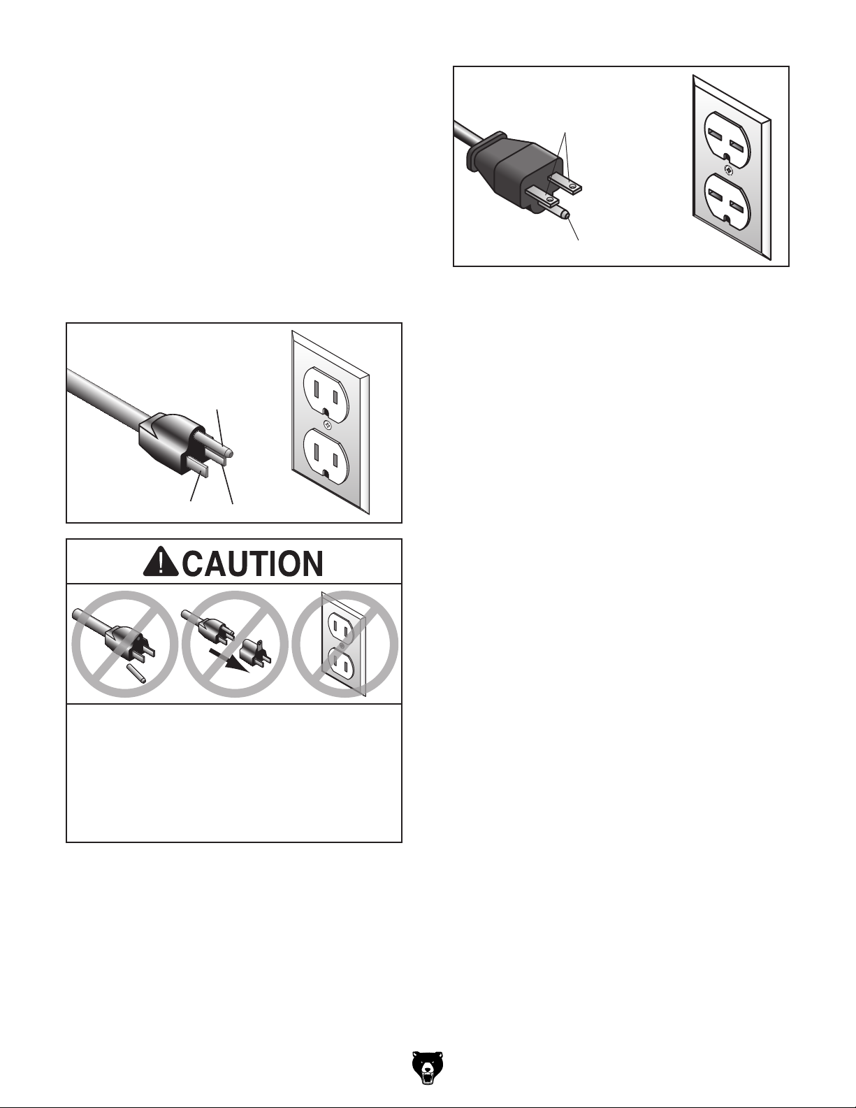
For 110V operation: This machine is equipped
with a power cord that has an equipment-grounding wire and a grounding plug (see following figure). The plug must only be inserted into a matching receptacle (outlet) that is properly installed
and grounded in accordance with all local codes
and ordinances.
For 220V operation: The plug specified under
“
page has a grounding prong that must be attached
to the equipment-grounding wire on the included
power cord. The plug must only be inserted into
a matching receptacle (see following figure) that
is properly installed and grounded in accordance
with all local codes and ordinances.
it will not fit the outlet, have a qualified
electrician install the proper outlet with a
We do not recommend using an extension cord
with this machine.
cord, only use it if absolutely necessary and only
on a temporary basis.
Extension cords cause voltage drop, which may
damage electrical components and shorten motor
life. Voltage drop increases as the extension cord
size gets longer and the gauge size gets smaller
(higher gauge numbers indicate smaller sizes).
Any extension cord used with this machine must
contain a ground wire, match the required plug
and receptacle, and meet the following requirements:
GROUNDED
5-15 RECEPTACLE
Grounding Prong
5-15 PLUG
GROUNDED
6-15 RECEPTACLE
Current Carrying Prongs
6-15 PLUG
Grounding Prong
Neutral Hot
SHOCK HAZARD!
Two-prong outlets do not meet the grounding
requirements for this machine. Do not modify
or use an adapter on the plug provided—if
verified ground.
Circuit Requirements for 220V” on the previous
Model G0778 (Mfd. Since 10/14)
Extension Cords
If you must use an extension
Minimum Gauge Size at 110V ..............12 AWG
Minimum Gauge Size at 220V .............14 AWG
Maximum Length (Shorter is Better).......50 ft.
-5-
Page 6
Voltage Conversion
Ground
Ground
The voltage conversion MUST be performed by
an electrician or qualified service personnel.
The voltage conversion procedure consists of
rewiring the main motor and installing the correct
plug. A wiring diagram is provided on Page 7 for
your reference.
4. Connect the main motor wires, as shown in
Figure 2, with wire nuts. Once snug, wrap
electrical tape around each wire nut and the
connected wires, to reduce the likelihood
of the wire nut vibrating loose during motor
operation.
220V (Rewired)
Items Needed Qty
• Wrench 7mm .............................................. 1
• Electrical Tape ............................ As Needed
• Plug 6-15 .................................................... 1
• Wire Stripper .............................. As Needed
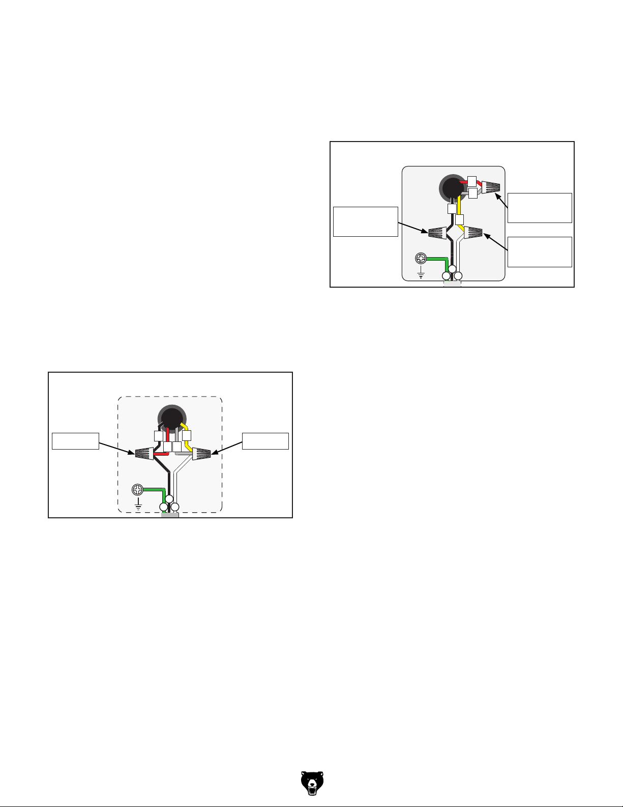
To convert Model G0778 to 220V:
1. DISCONNECT MACHINE FROM POWER!
2. Cut off included plug.
3. Open main motor junction box, then remove
wire nuts indicated in Figure 1.
110V (Prewired)
4
Remove Remove
1
3
2
3
Connect
2
1
4
Connect
and Tighten
and Tighten
Connect
and Tighten
Wt
Bl
Gn
Figure 2. Motor wires repositioned for 220V.
5. Close and secure the motor junction box.
6. Install a 6-15 plug on the end of the cord,
according to the instructions and wiring diagrams provided by the plug manufacturer.
—If the plug manufacturer did not include
instructions, the wiring of a generic NEMA
6-15 plug is illustrated on Page 7.
Bl
Gn
Wt
Figure 1. Location of components to be removed
and loosened.
-6-
Model G0778 (Mfd. Since 10/14)
Page 7

ACCESSORIES
Installing unapproved accessories may
order online at www.grizzly.com or call 1-800-523-4777
Accessories
cause machine to malfunction, resulting in
serious personal injury or machine damage.
To reduce this risk, only install accessories
recommended for this machine by Grizzly.
NOTICE
Refer to our website or latest catalog for
additional recommended accessories.
T26403—The Missing Shop Manual: Bandsaw
Dedicated to providing integral information about
woodworking tools and techniques that other
manuals overlook, the books in this series contain
safety facts, explanations about basic project set
up, and tips for maximizing tool performance. In
Bandsaw, you will find out how to best utilize this
essential workshop tool, and how to get the most
for your money by getting the most from your
equipment. Filled with clear diagrams and instructions, this pocket sized durable manual is ideal for
quick reference in the workshop. 112 pages, soft
cover.
T26783—New Complete Guide to Band Saws
This essential guide to woodworking's most versatile tool includes a thorough analysis on everything needed to know in order to purchase, set up,
use, and maintain a band saw. This book details
what woodworkers need to know before purchasing a saw - included the eight questions to ask
before buying a used saw - along with topics such
as a part-by-part overview of every component
of the saw, techniques of set up and alignment,
choosing the right blade, and understanding
hand positioning to provide any woodworker with
the most complete guide to a band saw. Special
sections are devoted to band saw accessories,
how to deal with common problems, and how to
maintain a band saw to keep it running effectively
and efficiently for years to come. 200 pages with
full color photos.
Figure 3. The Missing Shop Manual: Bandsaw.
Model G0778 (Mfd. Since 10/14)
Figure 4. New Complete Guide to Band Saws.
-7-
Page 8

T26402—The Bandsaw Book
Comprehensive, up-to-date guide with practical
information on set up, tuning, choosing blades,
and both basic and advanced techniques. Includes
information on the anatomy of a bandsaw, choosing the right one for you, how to select the correct
blades for your saw and applications, and how to
maintain it to keep it running for years to come.
201 pages, soft cover.
Figure 5. The Bandsaw Book.
T26401—Success With Bandsaws
One of the most accessible workshop power
tools is also one the most versatile: the bandsaw.
And this new entry in the popular Success with
series explores the many creative possibilities
of floor-standing, stand-mounted, and portable
bench-top models. With these practical instructions and color photographs, woodworkers can
quickly master basic skills such as ripping, cutting angles, and mirror cutting, then practice
advanced procedures like making dovetail, mortise and tenon joints and cutting variable-curve
edgesùand; even making their own money-saving
jigs and templates. There's also basic information
on bandsaw anatomy, blade selection, initial set
up, routine and periodic maintenance, dust control
techniques, and workshop safety. 176 pages.
G0710 —1 HP Wall Hanging Dust Collector
Mount this 1 HP Dust Collector to your wall and
keep precious floor space free of clutter. With 537
CFM, this Dust Collector will handle just about any
dust producing machine in your shop in a point-ofuse, dedicated setup. A simple mounting bracket
allows you to hang this dust collector on the wall,
or mount it to a bench or the floor. Very versatile!
Figure 6. Model G0710 1 HP Wall Hanging Dust
Collector
Figure 7. Success With Bandsaws.
-8-
Model G0778 (Mfd. Since 10/14)
Page 9
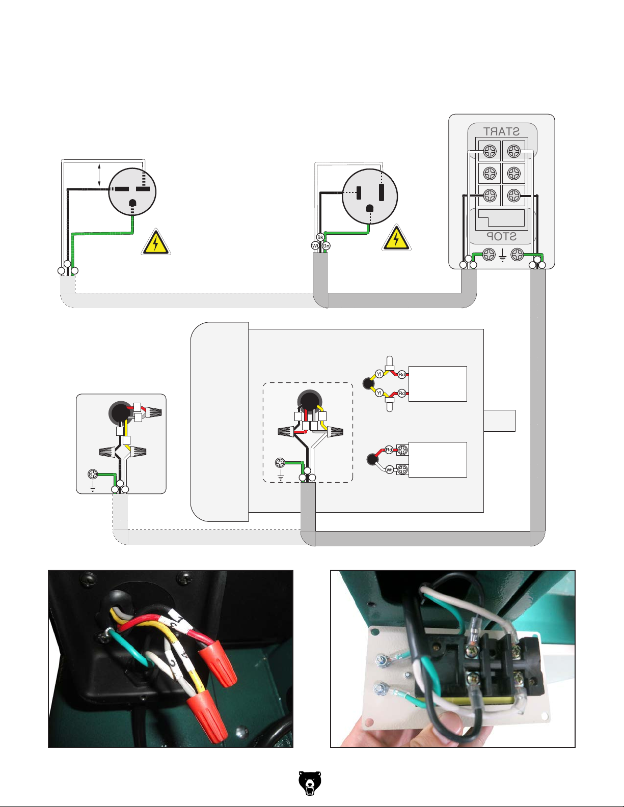
Electrical
Ground
Ground
START
STOP
PUSH BUTTON SWITCH
(viewed from behind)
Wt
VAC
Ground
Bl
Gn
Hot
220
Hot
(As Recommended)
Rewired to 220V
220V
Gn
220V
G
1
4
Wt
Bl
6-15 Plug
3
2
Rewired to 220V
Neutral
Hot
Ground
110V (Prewired)
4
1
3
2
Bl
Gn
Wt
110V
5-15 Plug
(Prewired)
Run
Capacitor
50MFD
250VAC
Start
Capacitor
300MFD
250VAC
Wt
Bl
Gn
Bl
Gn
Wt
Figure 8. 110V motor wiring. Figure 9. Push button switch wiring.
Model G0778 (Mfd. Since 10/14)
Rewired to 220V
-9-
Page 10
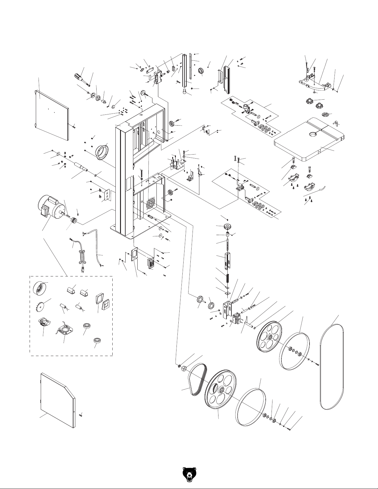
Main Parts Breakdown
127
124
2
93
96
92
91
96-1
96-2
90
96-4
97
203
140
10
88
12
21
142
143
204
96-3
96-11
9
96-10
11
8
5
95
144
96-5
7
4
76
141
94
6
1
139
55
26
23
138
27
161
22
121
122
145
33
162
24
113
137
25
28
114
146
29
103
30
31
34
164
32
102
66
157
116
117
115
135
136
100
101
38
39
158
89
150
159
63
35
36
37
42
160
66
54
40
111
104
105
37
56
58
59
60
61
62
64
151
54
41
104
50
51
67
57
72
52
53
112
65
68
69
70
43
129
130
131
71
44
75
76
132
133
77
118
78
119
120
123
160
125
126
128
134
3
-10 -
96-6
96-7
96-8
21
96-9
202
87
86
201
73
74
78
83
82
81
80
79
Model G0778 (Mfd. Since 10/14)
Page 11

Main Parts List
REF PART # DESCRIPTION REF PART # DESCRIPTION
1 P0778001 BODY 68 P0778068 SQUARE SHAFT 12 X 12MM
2 P0778002 UPPER WHEEL DOOR 69 P0778069 CAP SCREW M8-1.25 X 20
3 P0778003 LOWER WHEEL DOOR 70 P0778070 LOCK WASHER 8MM
4 P0778004 CAP SCREW M6-1 X 10 71 P0778071 FLAT WASHER 8MM
5 P0778005 LOCK WASHER 6MM 72 P0778072 SLEEVE
6 P0778006 CAP SCREW M5-.8 X 12 73 P0778073 UPPER WHEEL SHAFT BRACKET
7 P0778007 BIAS SHAFT 74 P0778074 ROLL PIN 5 X 35
8 P0778008 BIAS SHAFT CLAMP SEAT 75 P0778075 UPPER WHEEL SHAFT
9 P0778009 TENSION ADJUSTMENT HUB 76 P0778076 WAVY WASHER 15 X 22MM
10 P0778010 CAP SCREW M8-1.25 X 20 77 P0778077 UPPER WHEEL
11 P0778011 HEX NUT M8-1.25 78 P0778078 WHEEL TIRE
12 P0778012 TENSION HANDLE 79 P0778079 HEX BOLT M8-1.25 X 16
21 P0778021 CAP SCREW M6-1 X 10 80 P0778080 LOCK WASHER 8MM
22 P0778022 LOCK WASHER 8MM 81 P0778081 FLAT WASHER 8MM
23 P0778023 CAP SCREW M8-1.25 X 20 82 P0778082 BALL BEARING 6202ZZ
24 P0778024 LOCK KNOB M8-1.25 X 20 83 P0778083 INT RETAINING RING 35MM
25 P0778025 UPPER GUIDE POST SUPPORT 86 P0778086 HEX NUT M18-1.5
26 P0778026 FLAT HD SCR M4-.7 X 6 87 P0778087 LOCK WASHER 18MM
27 P0778027 SPRING TENSIONER 88 P0778088 LOWER WHEEL SHAFT
28 P0778028 ADJUSTMENT GEAR SHAFT 89 P0778089 LEFT BLADE COVER
29 P0778029 BUSHING 90 P0778090 HEX NUT M8-1.25
30 P0778030 GEAR SHAFT BRACKET 91 P0778091 SET SCREW M8-1.25 X 20
31 P0778031 LOCK WASHER 6MM 92 P0778092 SHAFT END CAP
32 P0778032 CAP SCREW M6-1 X 10 93 P0778093 FLANGE SCREW M5-.8 X 8
33 P0778033 COVER PLATE 94 P0778094 DUST PORT
34 P0778034 CAP SCREW M6-1 X 35 95 P0778095 FLANGE SCREW M6-1 X 10
35 P0778035 FLAT HD SCR M4-.7 X 6 96 P0778096 MOTOR 1-3/4 HP 220/110V 1-PH
36 P0778036 RACK 96-1 P0778096-1 MOTOR FAN COVER
37 P0778037 HAND KNOB M10-1.5 96-2 P0778096-2 MOTOR FAN
38 P0778038 GUIDE POST 96-3 P0778096-3 S CAPACITOR COVER
39 P0778039 CHANGE SHAFT 96-4 P0778096-4 S CAPACITOR 300M 250V 1-1/2 X 2-3/8
40 P0778040 PHLP HD SCR M6-1 X 12 96-5 P0778096-5 MOTOR JUNCTION BOX
41 P0778041 WASHER 6MM PLASTIC 96-6 P0778096-6 CENTRIFUGAL SWITCH
42 P0778042 LOCK NUT M6-1 96-7 P0778096-7 CONTACT PLATE
43 P0778043 UPPER BLADE GUIDE ASSEMBLY 96-8 P0778096-8 FRONT MOTOR BEARING 6205ZZ
44 P0778044 LOWER BLADE GUIDE ASSEMBLY 96-9 P0778096-9 REAR MOTOR BEARING 6203ZZ
50 P0778050 SLIDING BLADE GUARD 96-10 P0778096-10 R CAPACITOR COVER
51 P0778051 BLADE GUARD 96-11 P0778096-11 R CAPACITOR 50M 250V 1-1/2 X 2-3/8
52 P0778052 HEX BOLT M6-1 X 8 97 P0778097 KEY 5 X 5 X 20
53 P0778053 FLAT WASHER 6MM 100 P0778100 CAP SCREW M6-1 X 20
54 P0778054 FLANGE SCREW M6-1 X 8 101 P0778101 WHEEL COVER LATCH KNOB 6MM
55 P0778055 CAM 102 P0778102 LOCK NUT M6-1
56 P0778056 LOCK COLLAR 103 P0778103 ALIGNMENT PIN
57 P0778057 SET SCREW M5-.8 X 5 104 P0778104 FLANGE SCREW M5-.8 X 6
58 P0778058 TENSION ADJUSTMENT SCREW 105 P0778105 RIGHT BLADE COVER
59 P0778059 ADJUSTMENT SCREW BRACKET 111 P0778111 POINTER
60 P0778060 COMPRESSION SPRING 112 P0778112 HEX BOLT M6-1 X 12
61 P0778061 TENSION INDICATOR 113 P0778113 FLAT WASHER 8MM
62 P0778062 THREADED PLATE 114 P0778114 LOCK WASHER 8MM
63 P0778063 LOCK KNOB M8-1.25 X 45 115 P0778115 CAP SCREW M8-1.25 X 20
64 P0778064 KNOB M8-1.25 116 P0778116 WHEEL BRUSH
65 P0778065 FLAT WASHER 6MM 117 P0778117 FLANGE SCREW M5-.8 X 8
66 P0778066 PULL NUT M8-1.25 118 P0778118 HEX BOLT M8-1.25 X 35
67 P0778067 BRACKET
Model G0778 (Mfd. Since 10/14)
-11-
Page 12

Main Parts List (Continued)
REF PART # DESCRIPTION REF PART # DESCRIPTION
119 P0778119 LOCK WASHER 8MM 140 P0778140 POWER CORD 14G 3W 84" 5-15P
120 P0778120 TRUNNION BRACKET CAST IRON 141 P0778141 MOTOR CORD 14G 3C
121 P0778121 HEX BOLT M8-1.25 X 80 142 P0778142 FLANGE SCREW M5-.8 X 8
122 P0778122 HEX NUT M8-1.25 143 P0778143 STRAIN RELIEF
123 P0778123 POINTER 144 P0778144 SWITCH BOX REAR PLATE
124 P0778124 PHLP HD SCR M5-.8 X 6 145 P0778145 SWITCH BOX FRONT PLATE
125 P0778125 LOCK KNOB M10-1.5 146 P0778146 ON/OFF SWITCH 110/220V
126 P0778126 TABLE INSERT 150 P0778150 POINTER BRACKET
127 P0778127 TABLE PIN 151 P0778151 FLANGE SCREW M5-.8 X 12
128 P0778128 TABLE 157 P0778157 LEVER PLATE
129 P0778129 HEX BOLT M10-1.5 X 50 158 P0778158 HEX BOLT M8-1.25 X 20
130 P0778130 TRUNNION CLAMP SHOE 1PC 159 P0778159 LOCK WASHER 8MM
131 P0778131 TRUNNION CAST IRON 160 P0778160 FLAT WASHER 8MM
132 P0778132 SCALE 161 P0778161 SHIM PLASTIC
133 P0778133 FLANGE BOLT M6-1 X 12 162 P0778162 SET SCREW M6-1 X 6
134 P0778134 BLADE 106 X 3/8 X 0.35" 6TPI 164 P0778164 SET SCREW M8-1.25 X 10
135 P0778135 FLANGE SCREW M5-.8 X 8 201 P0778201 WHEEL LOWER ASSEMBLY
136 P0778136 PHLP HD SCR M4-.7 X 10 202 P0778202 RIBBED BELT 200J5
137 P0778137 PHLP HD SCR M5-.8 X 12 203 P0778203 MOTOR PULLEY
138 P0778138 EXT TOOTH WASHER 5MM 204 P0778204 SET SCREW M6-1 X 10
139 P0778139 HEX NUT M5-.8
-12-
Model G0778 (Mfd. Since 10/14)
Page 13
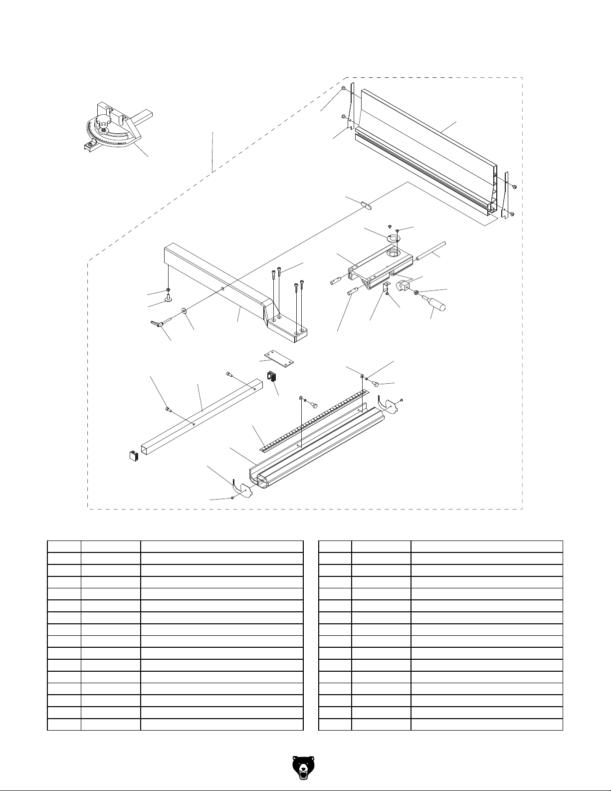
Fence Parts Breakdown
149-22
149-10
148
149-24
149-6
149
149-8
149-14
149-7
149-29
149-19
149-20
149-30
149-18
149-12
149-27
149-2
149-3
149-11
149-5
149-28
149-16
149-4
149-13
149-15
149-26
149-9
149-23
149-25
149-21
149-1
149-17
149-20
REF PART # DESCRIPTION REF PART # DESCRIPTION
148 P0778148 MITER GAUGE ASSEMBLY 149-15 P0778149-15 HEX NUT M8-1.25
149 P0778149 RESAW FENCE ASSEMBLY 149-16 P0778149-16 FLANGE SCREW M4-.7 X 6
149-1 P0778149-1 FRONT FENCE RAIL 540MM 149-17 P0778149-17 FRONT RAIL END CAP
149-2 P0778149-2 FENCE BASE 149-18 P0778149-18 FENCE MOUNTING PLATE
149-3 P0778149-3 FENCE SUPPORT MOUNTING ROD 149-19 P0778149-19 REAR RAIL END CAP
149-4 P0778149-4 LOCK ROD 149-20 P0778149-20 TAP SCREW M3.5 X 8
149-5 P0778149-5 SPRING PIECE 149-21 P0778149-21 SCALE
149-6 P0778149-6 LOCK HANDLE ASSEMBLY M8-1.25 X 44 149-22 P0778149-22 HEX NUT M6-1
149-7 P0778149-7 FENCE SUPPORT 505MM 149-23 P0778149-23 LOCK WASHER 6MM
149-8 P0778149-8 FLAT WASHER 8MM 149-24 P0778149-24 CAP SCREW M6-1 X 16
149-9 P0778149-9 LOCK HANDLE 149-25 P0778149-25 HEX BOLT M6-1 X 20
149-10 P0778149-10 FENCE REAR STANDOFF 149-26 P0778149-26 FLANGE SCREW M4-.7 X 8
149-11 P0778149-11 SCALE WINDOW 149-27 P0778149-27 FLAT WASHER 6MM
149-12 P0778149-12 CAP SCREW M6-1 X 25 149-28 P0778149-28 FENCE 505MM ALUMINUM
149-13 P0778149-13 LOCK CAM 149-29 P0778149-29 FENCE SUPPORT MOUNTING PLATE
149-14 P0778149-14 REAR FENCE RAIL 149-30 P0778149-30 FENCE END CAP
Model G0778 (Mfd. Since 10/14)
-13-
Page 14
302
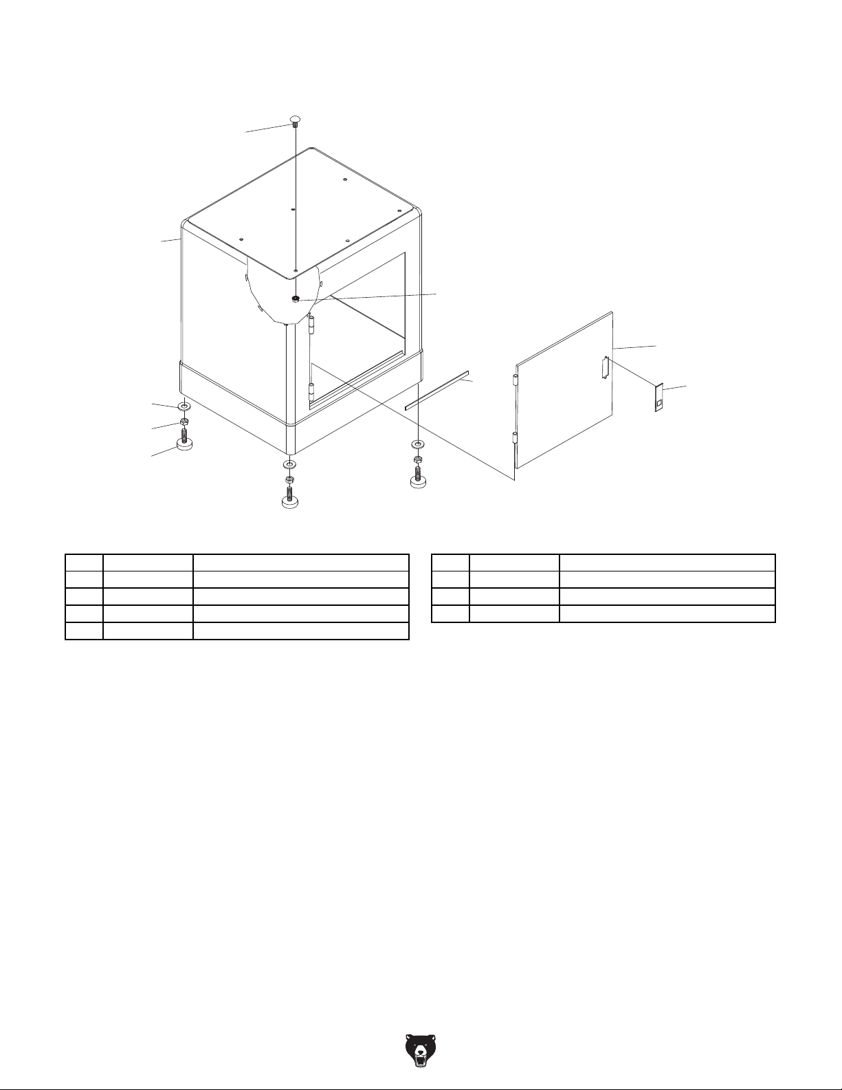
Stand Parts Breakdown
301
303
305
304
307
308
309
REF PART # DESCRIPTION REF PART # DESCRIPTION
301 P0778301 CARRIAGE BOLT M8-1.25 X 20 306 P0778306 LATCH ASSEMBLY
302 P0778302 STAND 307 P0778307 FLAT WASHER 3/8
303 P0778303 FLANGE NUT M8-1.25 308 P0778308 HEX NUT 3/8-16
304 P0778304 FOAM TAPE 309 P0778309 FOOT 3/8-16 X 1-3/4
305 P0778305 DOOR
306
-14-
Model G0778 (Mfd. Since 10/14)
Page 15
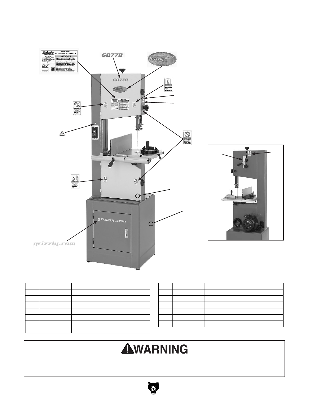
Labels & Cosmetics
REF PART # DESCRIPTION REF PART # DESCRIPTION
401 P0778401 MACHINE ID LABEL 409 P0778409 GRIZZLY NAMEPLATE
402 P0778402 READ MANUAL LABEL 410 P0778410 MODEL NUMBER LABEL
403 P0778403 UNPLUG BANDSAW LABEL 411 P0778411 BLADE GUARD ADJ LABEL
404 P0778404 GLASSES/RESPIRATOR LABEL 412 P0778412 BLADE TENSION SCALE/LABEL
405 P0778405 DO NOT OPEN LABEL 413 P0778413 GRIZZLY GREEN TOUCH-UP PAINT
406 P0778406 BLADE TENSION NOTICE LABEL 414 P0778414 GRIZZLY PUTTY TOUCH-UP PAINT
407 P0778407 HANDS NEAR BLADE LABEL 415 P0778415 GRIZZLY.COM LABEL
408 P0778408 ELECTRICITY LABEL
401
408
404
403
410
402
411
407
414
409
405
412
406
413
415
Rear of Machine
Safety labels help reduce the risk of serious injury caused by machine hazards. If any label comes
off or becomes unreadable, the owner of this machine MUST replace it in the original location
before resuming operations. For replacements, contact (800) 523-4777 or www.grizzly.com.
Model G0778 (Mfd. Since 10/14)
-15-
Page 16

-16 -
Model G0778 (Mfd. Since 10/14)
Page 17

MODEL G0457
14" INDUSTRIAL BANDSAW
OWNER'S MANUAL
COPYRIGHT © AUGUST, 2005 BY GRIZZLY INDUSTRIAL, INC. REVISED NOVEMBER, 2014 (MN)
WARNING: NO PORTION OF THIS MANUAL MAY BE REPRODUCED IN ANY SHAPE
OR FORM WITHOUT THE WRITTEN APPROVAL OF GRIZZLY INDUSTRIAL, INC.
(FOR MACHINES MANUFACTURED SINCE 10/14) #TR7412 PRINTED IN TA IWA N
Page 18

This manual provides critical safety instructions on the proper setup,
operation, maintenance, and service of this machine/tool. Save this
document, refer to it often, and use it to instruct other operators.
Failure to read, understand and follow the instructions in this manual
may result in fire or serious personal injury—including amputation,
electrocution, or death.
The owner of this machine/tool is solely responsible for its safe use.
This responsibility includes but is not limited to proper installation in
a safe environment, personnel training and usage authorization,
proper inspection and maintenance, manual availability and comprehension, application of safety devices, cutting/sanding/grinding tool
integrity, and the usage of personal protective equipment.
The manufacturer will not be held liable for injury or property damage
from negligence, improper training, machine modifications or misuse.
Some dust created by power sanding, sawing, grinding, drilling, and
other construction activities contains chemicals known to the State
of California to cause cancer, birth defects or other reproductive
harm. Some examples of these chemicals are:
• Lead from lead-based paints.
• Crystalline silica from bricks, cement and other masonry products.
• Arsenic and chromium from chemically-treated lumber.
Your risk from these exposures varies, depending on how often you
do this type of work. To reduce your exposure to these chemicals:
Work in a well ventilated area, and work with approved safety equipment, such as those dust masks that are specially designed to filter
out microscopic particles.
Page 19

Table of Contents
INTRODUCTION ............................................... 2
Manual Accuracy ........................................... 2
Contact Info.................................................... 2
Identification ................................................... 3
Machine Data Sheet ...................................... 4
SECTION 1: SAFETY ....................................... 6
Safety Instructions for Machinery .................. 6
Additional Safety Instructions
for Bandsaws ................................................. 8
SECTION 2: POWER SUPPLY ........................ 9
SECTION 3: SETUP ....................................... 12
Needed for Setup ......................................... 12
Unpacking .................................................... 12
Hardware Recognition Chart ....................... 13
Inventory ...................................................... 14
Clean Up ...................................................... 15
Site Considerations ...................................... 15
Assembly ..................................................... 16
Dust Collection ............................................. 19
Blade Tracking ............................................. 20
Test Run ...................................................... 21
Table Stop Calibration ................................. 21
Table Tilt Calibration .................................... 22
Table Alignment ........................................... 22
Fence Alignment .......................................... 23
Miter Gauge ................................................. 23
Blade Tensioning ......................................... 24
Adjusting Support Bearings ......................... 24
Blade Guide Adjustments ............................ 26
SECTION 5: ACCESSORIES ......................... 37
SECTION 6: MAINTENANCE ......................... 40
Schedule ...................................................... 40
Cleaning ....................................................... 40
Unpainted Cast Iron ..................................... 40
Lubrication ................................................... 40
Redressing Rubber Tires ............................. 42
SECTION 7: SERVICE ................................... 43
Troubleshooting ........................................... 43
Checking V-Belt ........................................... 45
Tensioning V-Belt......................................... 45
Replacing V-Belt .......................................... 46
Shimming Table ........................................... 47
Blade Lead ................................................... 47
Wheel Alignment .......................................... 49
SECTION 8: WIRING ...................................... 51
Wiring Safety Instructions ............................ 51
SECTION 9: PARTS ....................................... 53
Main ............................................................. 53
Components ................................................. 56
Stand ............................................................ 57
Labels .......................................................... 58
WARRANTY & RETURNS ............................. 61
SECTION 4: OPERATIONS ........................... 27
Basic Controls .............................................. 27
Overview ...................................................... 28
Workpiece Inspection................................... 29
Table Tilt ...................................................... 29
Guide Post ................................................... 30
Ripping ......................................................... 30
Crosscutting ................................................. 31
Resawing ..................................................... 31
Cutting Curves ............................................. 32
Stacked Cuts................................................ 33
Blade Information ......................................... 34
Blade Changes ............................................ 36
Page 20
INTRODUCTION
We are proud to provide a high-quality owner’s
manual with your new machine!
We
instructions, specifications, drawings, and photographs
contained inside. Sometimes we make mistakes,
but
also
means that
you receive
will be slightly different than what is shown in
the manual
If you find this to be the case, and the difference
between the manual and machine leaves you
confused about a procedure
check our website
for an updated version. W
manuals
and
www.grizzly.com
Alternatively, you can call our Technical Support
for help. Before calling, please write down the
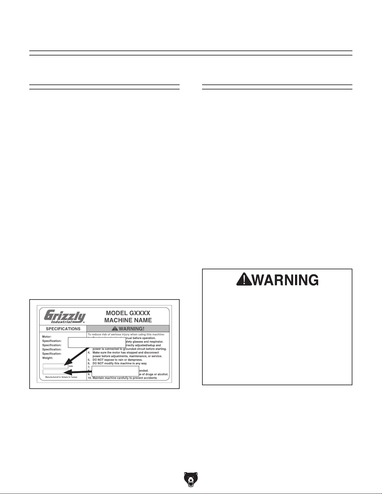
Manufacture Date
stamped
into the machine ID label (see below). This information helps us determine if updated documentation is available for your machine.
We stand behind our machines. If you have
any questions or need help, use the information
below to contact us. Before contacting, please get
the serial number and manufacture date of your
machine. This will help us help you faster.
We want your feedback on this manual. What did
you like about it? Where could it be improved?
Please take a few minutes to give us feedback.
Email: manuals@grizzly.com
Manual Accuracy
made every effort to be exact with the
our policy of continuous improvement
sometimes the machine
.
manual updates for free on our website at
.
and Serial Number
,
e post current
Contact Info
Grizzly Technical Support
1203 Lycoming Mall Circle
Muncy, PA 17756
Phone: (570) 546-9663
Email: techsupport@grizzly.com
Grizzly Documentation Manager
P.O. Box 2069
Bellingham, WA 98227-2069
Manufacture Date
Serial Number
For Your Own Safety Read Instruction
Manual Before Operating Bandsaw
a) Wear eye protection.
b) Do not remove jammed cutoff pieces
until blade has stopped.
c) Maintain proper adjustment of blade
tension, blade guides, and thrust
bearings.
d) Adjust upper guide to just clear
workpiece.
e) Hold workpiece firmly against table.
-2-
G0457 14" Industrial Bandsaw (Mfg. Since 5/11)
Page 21
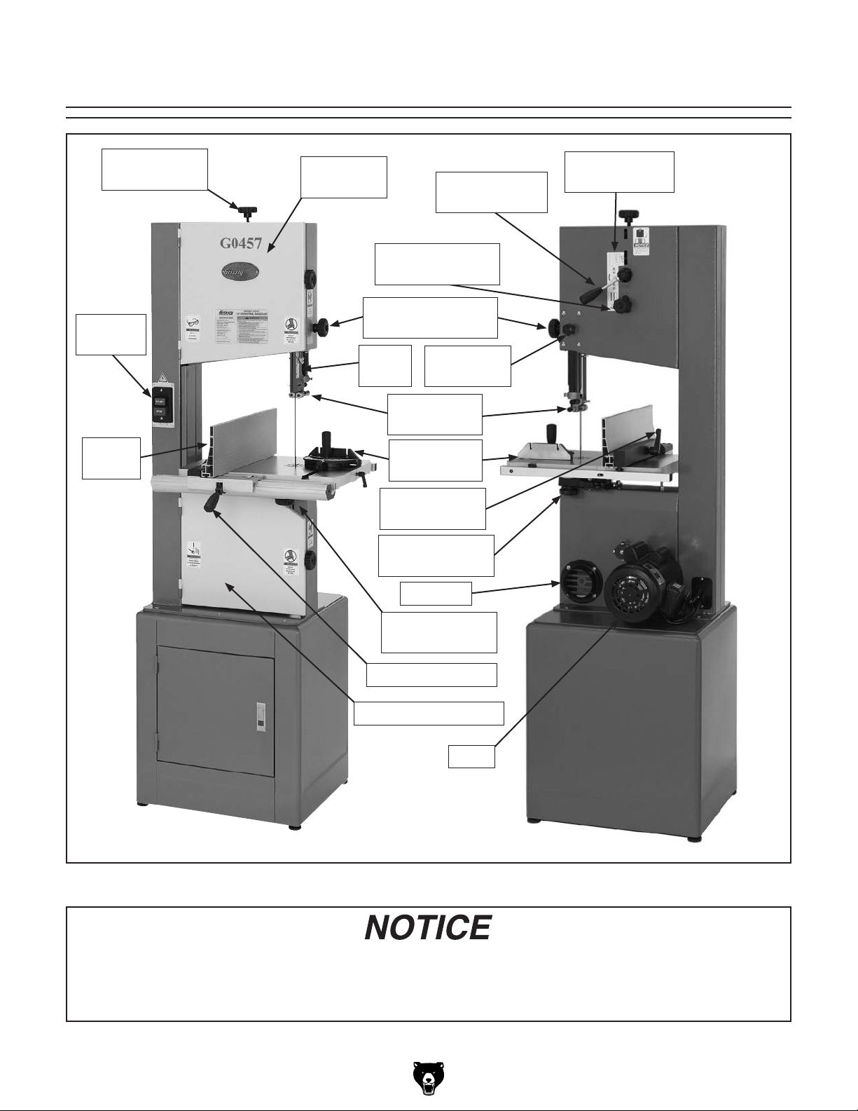
Identification
Blade Tension
Knob
ON/OFF
Switch
Resaw
Fence
Top Wheel
Cover
Guide Adjustment
Blade
Guard
Blade Tension
Quick Release
Blade Tracking
Adjustment Knob
Knob
Guide Post
Lock Knob
Blade Guide
Assembly
Miter Gauge
Assembly
Resaw Fence
Lock Handle
Table Trunnion
Hand Knob
Blade Tension
Scale
Dust Port
Table Tilt Scale
(Under Table)
Fence Lock Lever
Bottom Wheel Cover
Motor
Figure 1. Identification.
If you have never used this type of machine or equipment before, WE STRONGLY RECOMMEND
that you read books, review industry trade magazines, or get formal training before beginning
any projects. Regardless of the content in this section, Grizzly Industrial will not be held liable for
accidents caused by lack of training.
G0457 14" Industrial Bandsaw (Mfg. Since 5/11)
-3-
Page 22

Machine Data Sheet
MACHINE DATA
SHEET
Customer Service #: (570) 546-9663 · To Order Call: (800) 523-4777 · Fax #: (800) 438-5901
MODEL G0457 14" 2 HP DELUXE BANDSAW
Product Dimensions:
Weight.............................................................................................................................................................. 251 lbs.
Width (side-to-side) x Depth (front-to-back) x Height............................................................... 29-3/4 x 29-1/2 x 73 in.
Footprint (Length x Width)............................................................................................................... 21-1/2 x 18-1/4 in.
Shipping Dimensions:
Carton #1
Type........................................................................................................................................... Cardboard Box
Content................................................................................................................................................. Machine
Weight.................................................................................................................................................... 214 lbs.
Length x Width x Height............................................................................................................. 51 x 23 x 14 in.
Must Ship Upright.......................................................................................................................................... No
Carton #2
Type........................................................................................................................................... Cardboard Box
Content...................................................................................................................................................... Stand
Weight...................................................................................................................................................... 70 lbs.
Length x Width x Height............................................................................................................. 22 x 19 x 25 in.
Must Ship Upright.......................................................................................................................................... No
Electrical:
Power Requirement............................................................................................. 110V or 220V, Single-Phase, 60 Hz
Prewired Voltage.................................................................................................................................................. 220V
Full-Load Current Rating.................................................................................................... 19A at 110V, 9.5A at 220V
Minimum Circuit Size.......................................................................................................... 20A at 110V, 15A at 220V
Connection Type....................................................................................................................................... Cord & Plug
Power Cord Included.............................................................................................................................................. Yes
Power Cord Length................................................................................................................................................. 7 ft.
Power Cord Gauge......................................................................................................................................... 14 AWG
Plug Included.......................................................................................................................................................... Yes
Included Plug Type................................................................................................................................. 6-15 for 220V
Recommended Plug Type...................................................................................................................... 5-20 for 110V
Switch Type................................................................................................... ON/OFF Push Button Switch w/Padlock
-4-
Motors:
Main
Type................................................................................................................. TEFC Capacitor-Start Induction
Horsepower................................................................................................................................................ 2 HP
Phase............................................................................................................................................ Single-Phase
Amps.................................................................................................................................................... 19A/9.5A
Speed................................................................................................................................................ 1725 RPM
Power Transfer ....................................................................................................................... Poly-V Belt Drive
Bearings........................................................................................................ Sealed & Permanently Lubricated
The information contained herein is deemed accurate as of 11/25/2014 and represents our most recent product specifications.
Due to our ongoing improvement efforts, this information may not accurately describe items previously purchased.
G0457 14" Industrial Bandsaw (Mfg. Since 5/11)
PAGE 1 OF 3Model G0457
Page 23

Main Specifications:
Main Specifications
Bandsaw Size............................................................................................................................................ 14 in.
Max Cutting Width (Left of Blade)........................................................................................................ 13-1/2 in.
Max Cutting Width (Left of Blade) w/Fence......................................................................................... 12-1/4 in.
Max Cutting Height (Resaw Height).......................................................................................................... 10 in.
Blade Speeds..................................................................................................................................... 3000 FPM
Blade Information
Standard Blade Length............................................................................................................................ 106 in.
Blade Length Range.......................................................................................................... 105-3/4 – 107-1/4 in.
Blade Width Range.......................................................................................................................... 1/8 – 3/4 in.
Type of Blade Guides...................................................................................................................... Ball Bearing
Guide Post Adjustment Type....................................................................................................... Rack & Pinion
Has Quick-Release...................................................................................................................................... Yes
Table Information
Table Length........................................................................................................................................ 19-3/4 in.
Table Width....................................................................................................................................... 14-3/16 in.
Table Thickness.................................................................................................................................... 1-1/2 in.
Table Tilt............................................................................................................................ Left 8, Right 45 deg.
Table Tilt Adjustment Type..................................................................................................................... Manual
Floor-to-Table Height........................................................................................................................... 42-1/4 in.
Fence Locking Position.............................................................................................................................. Front
Fence is Adjustable for Blade Lead.............................................................................................................. Yes
Resaw Fence Attachment Included.............................................................................................................. Yes
Miter Gauge Included................................................................................................................................... Yes
Construction Materials
Table....................................................................................................................... Precision Ground Cast Iron
Trunnion............................................................................................................................................... Cast Iron
Fence...................................................................................................................... Deluxe Extruded Aluminum
Base/Stand............................................................................................................................. Pre-Formed Steel
Frame/Body............................................................................................................................ Pre-Formed Steel
Wheels................................................................................................................ Computer-Balanced Cast Iron
Tire.......................................................................................................................................................... Rubber
Wheel Cover ......................................................................................................................... Pre-Formed Steel
Paint Type/Finish....................................................................................................................... Powder Coated
Other Related Information
Wheel Diameter......................................................................................................................................... 14 in.
Wheel Width.......................................................................................................................................... 1-1/8 in.
Number of Dust Ports....................................................................................................................................... 1
Dust Port Size.............................................................................................................................................. 4 in.
Compatible Mobile Base........................................................................................................................ D2057A
Other Specifications:
Country of Origin .............................................................................................................................................. Taiwan
Warranty ........................................................................................................................................................... 1 Year
Approximate Assembly & Setup Time ........................................................................................................ 45 Minutes
Serial Number Location ....................................................................................................... ID Label on Upper Cover
ISO 9001 Factory .................................................................................................................................................. Yes
CSA, ETL, or UL Certified/Listed ........................................................................................................................... Yes
G0457 14" Industrial Bandsaw (Mfg. Since 5/11)
-5-
Page 24
SECTION 1: SAFETY
For Your Own Safety, Read Instruction
Manual Before Operating This Machine
The purpose of safety symbols is to attract your attention to possible hazardous conditions.
This manual uses a series of symbols and signal words intended to convey the level of importance of the safety messages. The progression of symbols is described below. Remember that
safety messages by themselves do not eliminate danger and are not a substitute for proper
accident prevention measures. Always use common sense and good judgment.
Indicates an imminently hazardous situation which, if not avoided,
WILL result in death or serious injury.
Indicates a potentially hazardous situation which, if not avoided,
COULD result in death or serious injury.
Indicates a potentially hazardous situation which, if not avoided,
MAY result in minor or moderate injury. It may also be used to alert
against unsafe practices.
This symbol is used to alert the user to useful information about
NOTICE
proper operation of the machine.
Safety Instructions for Machinery
OWNER’S MANUAL. Read and understand this
owner’s manual BEFORE using machine.
TRAINED OPERATORS ONLY. Untrained operators have a higher risk of being hurt or killed.
Only allow trained/supervised people to use this
machine. When machine is not being used, disconnect power, remove switch keys, or lock-out
machine to prevent unauthorized use—especially
around children. Make workshop kid proof!
DANGEROUS ENVIRONMENTS. Do not use
machinery in areas that are wet, cluttered, or have
poor lighting. Operating machinery in these areas
greatly increases the risk of accidents and injury.
MENTAL ALERTNESS REQUIRED. Full mental
alertness is required for safe operation of machinery. Never operate under the influence of drugs or
alcohol, when tired, or when distracted.
ELECTRICAL EQUIPMENT INJURY RISKS. You
can be shocked, burned, or killed by touching live
electrical components or improperly grounded
machinery. To reduce this risk, only allow qualified
service personnel to do electrical installation or
repair work, and always disconnect power before
accessing or exposing electrical equipment.
DISCONNECT POWER FIRST.
nect machine from power supply BEFORE making
adjustments, changing tooling, or servicing machine.
This prevents an injury risk from unintended startup
or contact with live electrical components.
EYE PROTECTION. Always wear ANSI-approved
safety glasses or a face shield when operating or
observing machinery to reduce the risk of eye
injury or blindness from flying particles. Everyday
eyeglasses are NOT approved safety glasses.
Always discon-
-6-
G0457 14" Industrial Bandsaw (Mfg. Since 5/11)
Page 25

WEARING PROPER APPAREL. Do not wear
clothing, apparel or jewelry that can become
entangled in moving parts. Always tie back or
cover long hair. Wear non-slip footwear to avoid
accidental slips, which could cause loss of workpiece control.
HAZARDOUS DUST. Dust created while using
machinery may cause cancer, birth defects, or
long-term respiratory damage. Be aware of dust
hazards associated with each workpiece material,
and always wear a NIOSH-approved respirator to
reduce your risk.
HEARING PROTECTION. Always wear hearing protection when operating or observing loud
machinery. Extended exposure to this noise
without hearing protection can cause permanent
hearing loss.
REMOVE ADJUSTING TOOLS. Tools left on
machinery can become dangerous projectiles
upon startup. Never leave chuck keys, wrenches,
or any other tools on machine. Always verify
removal before starting!
USE CORRECT TOOL FOR THE JOB. Only use
this tool for its intended purpose—do not force
it or an attachment to do a job for which it was
not designed. Never make unapproved modifications—modifying tool or using it differently than
intended may result in malfunction or mechanical
failure that can lead to personal injury or death!
AWKWARD POSITIONS. Keep proper footing
and balance at all times when operating machine.
Do not overreach! Avoid awkward hand positions
that make workpiece control difficult or increase
the risk of accidental injury.
CHILDREN & BYSTANDERS. Keep children and
bystanders at a safe distance from the work area.
Stop using machine if they become a distraction.
FORCING MACHINERY. Do not force machine.
It will do the job safer and better at the rate for
which it was designed.
NEVER STAND ON MACHINE. Serious injury
may occur if machine is tipped or if the cutting
tool is unintentionally contacted.
STABLE MACHINE. Unexpected movement during operation greatly increases risk of injury or
loss of control. Before starting, verify machine is
stable and mobile base (if used) is locked.
USE RECOMMENDED ACCESSORIES. Consult
this owner’s manual or the manufacturer for recommended accessories. Using improper accessories will increase the risk of serious injury.
UNATTENDED OPERATION. To reduce the
risk of accidental injury, turn machine OFF and
ensure all moving parts completely stop before
walking away. Never leave machine running
while unattended.
MAINTAIN WITH CARE. Follow all maintenance
instructions and lubrication schedules to keep
machine in good working condition. A machine
that is improperly maintained could malfunction,
leading to serious personal injury or death.
CHECK DAMAGED PARTS. Regularly inspect
machine for any condition that may affect safe
operation. Immediately repair or replace damaged
or mis-adjusted parts before operating machine.
MAINTAIN POWER CORDS. When disconnecting cord-connected machines from power, grab
and pull the plug—NOT the cord. Pulling the cord
may damage the wires inside. Do not handle
cord/plug with wet hands. Avoid cord damage by
keeping it away from heated surfaces, high traffic
areas, harsh chemicals, and wet/damp locations.
GUARDS & COVERS. Guards and covers reduce
accidental contact with moving parts or flying
debris. Make sure they are properly installed,
undamaged, and working correctly.
G0457 14" Industrial Bandsaw (Mfg. Since 5/11)
EXPERIENCING DIFFICULTIES. If at any time
you experience difficulties performing the intended operation, stop using the machine! Contact our
Technical Support at (570) 546-9663.
-7-
Page 26

Additional Safety Instructions for Bandsaws
BLADE CONDITION. Do not operate with dull,
cracked or badly worn blade. Dull blades require
more effort to use and are difficult to control.
Inspect blades for cracks and missing teeth before
each use.
HAND PLACEMENT. Never position fingers or
thumbs in line with the cut. Serious personal injury
could occur.
GUARDS. Do not operate this bandsaw without
the blade guard in place.
BLADE REPLACEMENT. When replacing blades,
make sure teeth face toward the workpiece and
the blade is properly tensioned before operating.
WORKPIECE HANDLING. Never hold small
workpieces with your fingers during a cut. Always
support/feed the workpiece with push stick, table
support, vise, or some type of clamping fixture.
CUTTING TECHNIQUES. Plan your cuts so you
always cut out of the wood. DO NOT back the
workpiece away from the blade while the saw is
running. If you need to back the work out, turn the
bandsaw OFF and wait for the blade to come to a
complete stop, and DO NOT twist or put excessive
stress on the blade while backing work away.
BLADE SPEED. Allow blade to reach full speed
before cutting.
LEAVING WORK AREA. Never leave a machine
running and unattended. Allow the bandsaw to
come to a complete stop before you leave it unattended.
FEED RATE. Always feed stock evenly and
smoothly. DO NOT force or twist blade while cutting, especially when sawing small radii.
WORKPIECE MATERIAL. This machine is
designed to cut wood only. It is not designed to
cut metal or use cutting fluid.
MAINTENANCE/SERVICE. All inspections,
adjustments, and maintenance are to be done
with the power OFF and the plug removed from
the outlet. Wait for all moving parts to come to a
complete stop.
BLADE CONTROL. Do not attempt to stop or
slow the blade with your hand or a workpiece.
Allow the blade to stop on its own, unless your
machine is equipped with a brake.
EXPERIENCING DIFFICULTIES. If at any time
you are experiencing difficulties performing the
intended operation, stop using the machine!
Contact our Technical Support Department at
(570) 546-9663.
Like all machinery there is potential danger
when operating this machine. Accidents are
frequently caused by lack of familiarity or
failure to pay attention. Use this machine
with respect and caution to lessen the possibility of operator injury. If normal safety
precautions are overlooked or ignored, serious personal injury may occur.
-8-
No list of safety guidelines can be complete.
Every shop environment is different. Always
consider safety first, as it applies to your
individual working conditions. Use this and
other machinery with caution and respect.
Failure to do so could result in serious personal injury, damage to equipment, or poor
work results.
G0457 14" Industrial Bandsaw (Mfg. Since 5/11)
Page 27

SECTION 2: POWER SUPPLY
Before installing the machine, consider the availability and proximity of the required power supply
circuit. If an existing circuit does not meet the
requirements for this machine, a new circuit must
be installed. To minimize the risk of electrocution,
fire, or equipment damage, installation work and
electrical wiring must be done by an electrician or
qualified service personnel in accordance with all
applicable codes and standards.
Electrocution, fire, or
equipment damage may
occur if machine is not
correctly grounded and
connected to the power
The full-load current rating is the amperage a
machine draws at 100% of the rated output power.
On machines with multiple motors, this is the
amperage drawn by the largest motor or sum of all
motors and electrical devices that might operate
at one time during normal operations.
The full-load current is not the maximum amount
of amps that the machine will draw. If the machine
is overloaded, it will draw additional amps beyond
the full-load rating.
If the machine is overloaded for a sufficient length
of time, damage, overheating, or fire may result—
especially if connected to an undersized circuit.
To reduce the risk of these hazards, avoid overloading the machine during operation and make
sure it is connected to a power supply circuit that
meets the specified circuit requirements.
For your own safety and protection of
Note: Circuit requirements in this manual apply to
a dedicated circuit—where only one machine will
be running on the circuit at a time. If machine will
be connected to a shared circuit where multiple
machines may be running at the same time, consult an electrician or qualified service personnel to
ensure circuit is properly sized for safe operation.
A power supply circuit includes all electrical
equipment between the breaker box or fuse panel
in the building and the machine. The power supply circuit used for this machine must be sized to
safely handle the full-load current drawn from the
machine for an extended period of time. (If this
machine is connected to a circuit protected by
fuses, use a time delay fuse marked D.)
This machine is prewired to operate on a 220V
power supply circuit that has a verified ground and
meets the following requirements:
This machine can be converted to operate on a
110V power supply (refer to Voltage Conversion
instructions) that has a verified ground and meets
the following requirements:
Availability
supply.
Full-Load Current Rating
Circuit Information
property, consult an electrician if you are
unsure about wiring practices or electrical
codes in your area.
Full-Load Current Rating at 220V .... 9.5 Amps
Full-Load Current Rating at 110V ...... 19 Amps
G0457 14" Industrial Bandsaw (Mfg. Since 5/11)
Circuit Requirements for 220V
Nominal Voltage ........................................220V
Cycle .......................................................... 60 Hz
Phase ........................................... Single-Phase
Circuit Rating ...................................... 15 Amps
Plug/Receptacle ............................. NEMA 6 -15
Circuit Requirements for 110V
Nominal Voltage ........................................ 110V
Cycle .......................................................... 60 Hz
Phase ........................................... Single-Phase
Circuit Rating ...................................... 20 Amps
Plug/Receptacle ............................. NEMA 5-20
Cord ........“ S ”-Type, 3-Wire, 12 AWG, 300 VAC
-9-
Page 28
Improper connection of the equipment-grounding
wire can result in a risk of electric shock. The
wire with green insulation (with or without yellow
stripes) is the equipment-grounding wire. If repair
or replacement of the power cord or plug is necessary, do not connect the equipment-grounding
wire to a live (current carrying) terminal.
Check with a qualified electrician or service personnel if you do not understand these grounding
requirements, or if you are in doubt about whether
the tool is properly grounded. If you ever notice
that a cord or plug is damaged or worn, disconnect it from power, and immediately replace it with
a new one.
Grounding Requirements
This machine MUST be grounded. In the event
of certain malfunctions or breakdowns, grounding
reduces the risk of electric shock by providing a
path of least resistance for electric current.
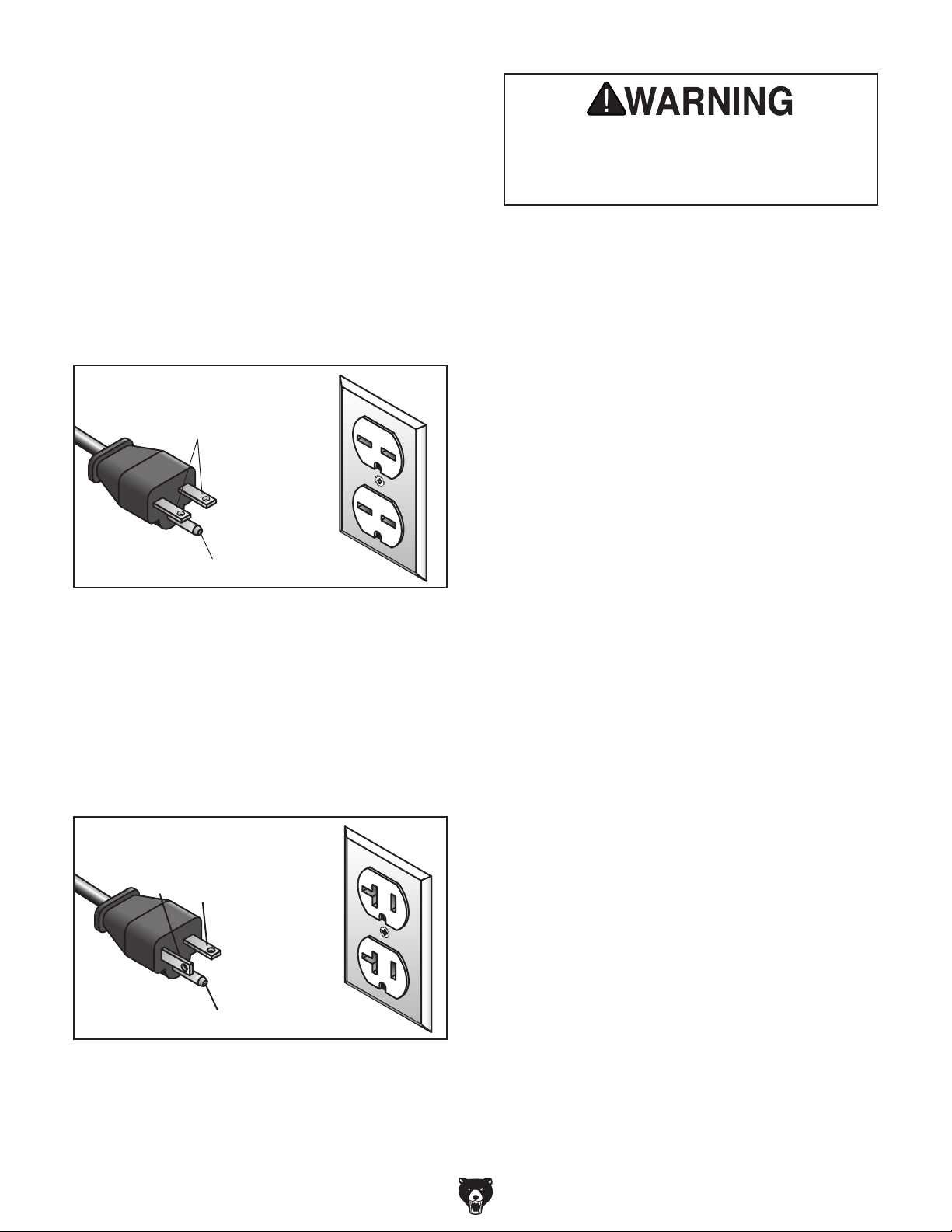
For 220V operation: This machine is equipped
with a power cord that has an equipment-grounding wire and a grounding plug (see following figure). The plug must only be inserted into a matching receptacle (outlet) that is properly installed
and grounded in accordance with all local codes
and ordinances.
For 110V operation: The plug specified in the
circuit requirements has a grounding prong that
must be attached to the equipment-grounding
wire inside the included power cord. The plug
must only be inserted into a matching receptacle
(see following figure) that is properly installed and
grounded in accordance with all local codes and
ordinances.
GROUNDED
6-15 RECEPTACLE
Current Carrying Prongs
6-15 PLUG
Serious injury could occur if you connect
the machine to power before completing the
setup process. DO NOT connect to power
until instructed later in this manual.
Grounding Prong
Figure 2. Typical 6-15 plug and receptacle.
GROUNDED
5-20 RECEPTACLE
Hot
Neutral
5-20 PLUG
Grounding Prong
Figure 3. Typical 5-20 plug and receptacle.
-10 -
G0457 14" Industrial Bandsaw (Mfg. Since 5/11)
Page 29

Extension Cords
We do not recommend using an extension cord
with this machine.
cord, only use it if absolutely necessary and only
on a temporary basis.
Extension cords cause voltage drop, which can
damage electrical components and shorten motor
life. Voltage drop increases as the extension cord
size gets longer and the gauge size gets smaller
(higher gauge numbers indicate smaller sizes).
Any extension cord used with this machine must
be in good condition and contain a ground wire
and matching plug/receptacle. Additionally, it must
meet the following size requirements:
The ON/OFF switch can be disabled and locked
by inserting a padlock through the ON button,
as shown. Locking the switch in this manner can
prevent unauthorized operation of the machine,
which is especially important if the machine is not
stored inside an access-restricted building.
IMPORTANT:
only restricts its function. It is not a substitute
for disconnecting power from the machine when
adjusting or servicing.
Disabling & Locking
If you must use an extension
Minimum Gauge Size at 110V ..............12 AWG
Minimum Gauge Size at 220V .............14 AWG
Maximum Length (Shorter is Better).......50 ft.
Voltage Conversion
The voltage conversion MUST be performed by
a qualified electrician. To perform the voltage
conversion, replace the power cord, install the
correct plug, and rewire the motor to the new voltage, according to the provided wiring diagram on
Page 52.
Switch
Locking the switch with a padlock
Padlock
Shaft
Figure 4. Switch disabled by a padlock.
Note: If the diagram included on the motor con-
flicts with the one in this manual, the motor may
have changed since the manual was printed. Use
the diagram provided inside the motor wiring junction box.
To convert the machine to 110V:
1. DISCONNECT MACHINE FROM POWER!
2. Replace the power cord with one that match-
es the cord specifications under Circuit
Recommendations for 110V on Page 9.
3. Replace the 6-15 plug on the power cord with
a NEMA 5-20 plug.
4. Re-wire the motor as illustrated in the wiring
diagram.
Children or untrained people can be
seriously injured by this machine. This
risk increases with unsupervised operation.
To help prevent unsupervised operation,
disable and lock the switch before leaving
machine unattended! Place key in a wellhidden or secure location.
NOTICE
The padlock shaft diameter is important to
the disabling function of the switch. With
any padlock used to lock the switch, test
the switch after installation to ensure that it
is properly disabled.
0.12"–0.15"
G0457 14" Industrial Bandsaw (Mfg. Since 5/11)
-11-
Page 30

SECTION 3: SETUP
Needed for Setup
This machine presents
serious injury hazards
to untrained users. Read
through this entire manual to become familiar with
the controls and operations before starting the
machine!
Wear safety glasses during the entire setup process!
This machine and its components are very heavy.
Get lifting help or use
power lifting equipment
such as a forklift to move
heavy items.
The following are needed to complete the setup
process, but are not included with your machine:
Description Qty
• Safety Glasses (for each person) ............... 1
• Assistant ..................................................... 1
• Cleaner/Degreaser ..................... As Needed
• Disposable Shop Rags ............... As Needed
• Wrenches or Sockets 13mm ...................... 2
• Wrench or Socket 10mm ............................ 1
• Wrench 14mm ............................................ 1
• Hex Wrench 4mm ....................................... 1
• Hex Wrench 5mm ....................................... 1
• Phillips Screwdriver .................................... 1
• Machinist's Square ..................................... 1
• Ruler ........................................................... 1
• Straightedge ............................................... 1
• Feeler Gauge 0.016" .................................. 1
• Dust Collector ............................................. 1
• Dust Hoses ................................................. 1
Unpacking
-12-
Your machine was carefully packaged for safe
transportation. Remove the packaging materials
from around your machine and inspect it. If you
discover the machine is damaged, please imme-
diately call Customer Service at (570) 546-9663
for advice.
Save the containers and all packing materials for
possible inspection by the carrier or its agent.
Otherwise, filing a freight claim can be difficult.
When you are completely satisfied with the condition of your shipment, inventory the contents.
G0457 14" Industrial Bandsaw (Mfg. Since 5/11)
Page 31

Hardware Recognition Chart
G0457 14" Industrial Bandsaw (Mfg. Since 5/11)
-13-
Page 32

Inventory
The following is a list of items shipped with your
machine. Before beginning setup, lay these items
out and inventory them.
If any non-proprietary parts are missing (e.g. a
nut or a washer), we will gladly replace them; or
for the sake of expediency, replacements can be
obtained at your local hardware store.
A
B
Contents (Figures 5–6) Qty
A. Bandsaw Unit ............................................. 1
B. Cabinet Stand ............................................. 1
C. F e e t
D. Motor .......................................................... 1
E. Blade Tension Knob ................................... 1
F. Lever Handle (Quick Release) ................... 1
G. Table ........................................................... 1
H. Trunnion Hand Knobs M10-1.5 (Table) ....... 2
I. Miter Gauge ................................................ 1
J. Fence Assembly ......................................... 1
K. Resaw Fence ............................................. 1
L. Front Rail .................................................... 1
M. Rear Rail .................................................... 1
N. Moving Plate (Fence).................................. 1
O. Lever Handle w/Nut (Fence) ....................... 1
P. Locking Adjustment Handle (Fence) .......... 1
Hardware (Not shown)
• Cap Screws M8-1.25 x 25 (Motor) .............. 2
• Lock Washers 8mm (Motor) ....................... 2
• Fender Washers 8mm (Motor) ................... 2
• Flat Washers 6mm (Front Rail) .................. 2
• Lock Washers 6mm (Front Rail) ................. 2
• Hex Bolts M6-1 x 20 (Front Rail) ................ 2
• Cap Screws M6-1 x 16 (Rear Rail) ............. 2
• Flat Washer 8mm (Fence) .......................... 1
• Flange Screw (Blade Tension Knob) .......... 1
• Hex Bolt M8-1.25 x 80 (Positive Stop) ........ 1
• Hex Nut M8-1.25 (Positive Stop) ................ 1
• Carriage Bolts M8-1.25 x 20 (Stand) .......... 6
• Flange Nuts M8-1.25 (Stand) ..................... 6
• Hex Nut M8-1.25 (Quick Release) .............. 1
• Hex Nuts
• Flat Washers 10mm (Feet) ......................... 4
• Hex Wrench 6mm ....................................... 1
3
⁄8 -16 (Sta n d) ...................................... 4
3
⁄8 -16 (Feet) ................................. 4
F
E
Figure 5. Bandsaw, stand, motor, and
G
I
Figure 6. Table, miter gauge, and hardware
P
O
N
Figure 7. Main fence components.
D
C
components
H
bags.
J
K
L
M
-14-
G0457 14" Industrial Bandsaw (Mfg. Since 5/11)
Page 33

Clean Up
Site Considerations
The unpainted surfaces are coated with a waxy
oil to prevent corrosion during shipment. Remove
this protective coating with a solvent cleaner or
degreaser. For thorough cleaning, some parts
must be removed. For optimum performance,
clean all moving parts or sliding contact surfaces. Avoid chlorine-based solvents, such as
acetone or brake parts cleaner that may damage
painted surfaces. Always follow the manufacturer’s instructions when using any type of cleaning
product.
Gasoline and petroleum
products have low flash
points and can explode
or cause fire if used to
clean machinery. DO
NOT use these products
to clean the machinery.
Floor Load
Refer to the Machine Data Sheet for the weight
and footprint specifications of your machine.
Some residential floors may require additional
reinforcement to support both the machine and
operator.
Placement Location
Consider existing and anticipated needs, size of
material to be processed through each machine,
and space for auxiliary stands, work tables or
other machinery when establishing a location for
your new machine. See Figure 8 for the minimum
working clearances.
29¾"
Many cleaning solvents
are toxic if inhaled.
Minimize your risk by only
using these products in a
well ventilated area.
29½"
Figure 8. Working clearances.
Children and visitors may be
seriously injured if unsupervised around this machine.
Lock entrances to the shop
or disable start switch or
power connection to prevent
unsupervised use.
G0457 14" Industrial Bandsaw (Mfg. Since 5/11)
-15-
Page 34
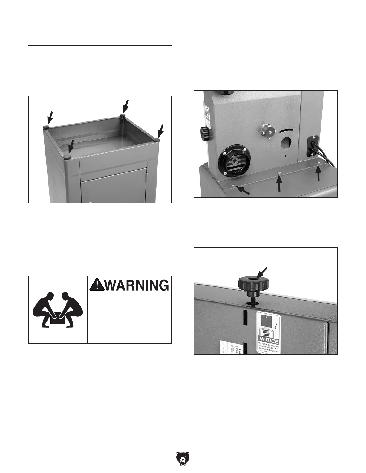
Assembly
4. With the help of an assistant, set the bandsaw
unit onto the stand, align the mounting holes,
then open the door on the cabinet stand.
To assemble the bandsaw:
1. Turn the cabinet stand upside down and
install the feet, as shown in Figure 9.
Figure 9. Installing feet on cabinet.
2. Set the cabinet upright, move it to its final
position, then adjust the feet so the cabinet is
level side-to-side and front-to-back.
5. Have your assistant hold the bandsaw while
you secure the body to the stand with the carriage bolts and flange nuts (Figure 10).
Figure 10. Securing the body to the stand.
6. Slide the blade tension knob over the thread-
ed shaft, as shown in Figure 11, and secure
the knob with the flange screw.
3. Secure the position of the feet by tightening
the hex nut/washers against the stand.
The bandsaw body is
heavy. DO NOT over-exert
yourself while unpacking or moving your
machine—get assistance
from another person.
Flange
Screw
Figure 11. Blade tension knob installed.
-16 -
G0457 14" Industrial Bandsaw (Mfg. Since 5/11)
Page 35

7. Thread an M8-1.25 hex nut all the way onto
the quick release lever, as shown in Figure
12, then thread the lever into the quick
release hub and tighten the hex nut against
the hub to lock the lever in place.
Hex Nut
9. From the inside of the bandsaw, loosely fasten the motor to the body with the cap screws
and flat washers, as shown in Figure 14.
Wheel Removed
for Clarity
Figure 14. Installing motor (inside view).
Figure 12. Quick release lever installed.
8. Have an assistant hold the motor in position
against the backside of the frame, as shown
in Figure 13.
Figure 13. Installing motor (outside view).
10. Place the belt on the pulleys and pivot the
motor so the belt is tight, then tighten the cap
screws. Refer to Tensioning V-Belt on Page
45 to properly tension the drive belt.
11. Refer to Wiring on Page 51 and wire the
motor to the switch cord.
12. Remove the blade from the top and bottom
wheels, then remove the table pin and table
insert from the table.
13. Place the table bolts through the trunnions.
14. Thread the table trunnion hand knobs onto
the table bolts to secure the table (Figure
15).
G0457 14" Industrial Bandsaw (Mfg. Since 5/11)
Hand
Knob
Figure 15. Table installed on trunnions.
-17-
Page 36

15. Replace the blade, and for now, only put
enough tension on it to keep it on the
wheels.
16. Re-install the table pin and table insert.
17. Fasten the rear rail to the back of the table
with the four M6-1 x 16 cap screws, as shown
in Figure 16.
19. Install the handle on the fence assembly
(Figure 18), and tighten the hex nut against
the fence pivot block to secure the handle.
Pivot Block
Hex Nut
Figure 18. Handle installed on fence assembly.
20. Place the 8mm flat washer on the locking
adjustment handle and slide it through the
hole in the fence.
Figure 16. Rear rail installed.
18. Attach the front rail to the front of the bandsaw
table with the two M6-1 x 20 hex bolts, 6mm
lock washers and flat washers, as shown in
Figure 17.
Figure 17. Installed front rail.
21. Thread the moving plate onto the end of the
locking adjustment handle threads.
22. Slide the resaw fence over the moving plate,
as shown in Figure 19, so the moving plate
fits inside the channel of the resaw fence.
Locking
Adjustment
Handle
Figure 19. Attaching resaw fence to standard
fence.
Moving
Plate
-18-
G0457 14" Industrial Bandsaw (Mfg. Since 5/11)
Page 37

23. Pull the handle up and place the fence
assembly on the fixed rail as shown in Figure
20.
Figure 20. Correctly installed fence.
24. Push the handle down to lock the fence
assembly in place.
25. Position the resaw fence evenly on the table
and use the locking adjustment handle to lock
it in place.
Dust Collection
DO NOT operate the Model G0457 without an
adequate dust collection system. This saw
creates substantial amounts of wood dust
while operating. Failure to use a dust collection system can result in short and long-term
respiratory illness.
Recommended CFM at Dust Port: 400 CFM
Do not confuse this CFM recommendation with
the rating of the dust collector. To determine the
CFM at the dust port, you must consider these
variables: (1) CFM rating of the dust collector,
(2) hose type and length between the dust collector and the machine, (3) number of branches
or wyes, and (4) amount of other open lines
throughout the system. Explaining how to calculate these variables is beyond the scope of
this manual. Consult an expert or purchase a
good dust collection "how-to" book.
26. Thread the M8-1.25 hex nut halfway onto the
M8-1.25 x 80 hex bolt (this is the positive stop
bolt).
27. Thread the positive stop bolt into the threaded hole on bandsaw body as shown in Figure
21.
Positive Stop
Figure 21. Installed positive stop bolt.
To connect a dust collection hose:
1. Fit the 4" dust hose over the dust port, as
shown in Figure 22, and secure in place with
a hose clamp.
2. Tug the hose to make sure it does not come
off.
Note: A tight fit is necessary for proper per-
formance.
G0457 14" Industrial Bandsaw (Mfg. Since 5/11)
Figure 22. Dust hose attached to dust port.
-19 -
Page 38

Blade Tracking
Blade Centered
on Peak of Crown
Blade
Centered
on
Wheel
Wheel
The blade tracking is primarily affected by the
tilt of the upper wheel, also known as "Center
Tracking"; and the alignment of both wheels, also
known as "Coplanar Tracking." (For Coplanar
Tracking, see the Wheel Alignment instructions
on Page 49.)
The wheels on the Model G0457 were aligned at
the factory, so Center Tracking is the only adjustment that needs to be performed when the saw
is new.
Figure 23. Center tracking profiles.
To center track the blade:
1. DISCONNECT BANDSAW FROM POWER!
2. Adjust the upper and lower guide bearings
3. Open the upper wheel cover.
4. Adjust blade tension until the mark on the
5. Spin the upper wheel by hand at least three
and support bearings as far away as possible
from the blade.
blade tension scale matches the size of the
installed blade.
The cast iron spokes may have sharp edges
and the blade teeth may extend beyond the
edge of the wheel, creating a laceration hazard. Be careful when turning the wheels by
hand.
times and watch how the blade rides on the
crown of the wheel. Refer to Figure 23 for an
illustration of this concept.
—If the blade rides in the center of the
upper wheel and is centered on the peak
of the wheel crown, then the bandsaw is
already tracked properly and no further
adjustments are needed at this time.
—If the blade does not ride in the center
of the upper wheel and is not centered
on the peak of the wheel crown, then
continue with the following steps.
6. Loosen the tracking control lock knob (Figure
24) so that the tracking control knob will
rotate for adjustments.
Tracking
Control Lock
Knob
Figure 24. Location of tracking control knob.
7. Spin the upper wheel with one hand and
rotate the tracking control knob with the other
hand to make the blade ride in the center of
the bandsaw wheel tire.
8. Tighten the tracking control lock knob and
close the upper wheel cover.
For the best performance from your saw, regularly
maintain the proper tracking of the blade.
Tracking Control
Knob
NOTICE
Changes in the blade tension may change
the blade tracking.
-20-
G0457 14" Industrial Bandsaw (Mfg. Since 5/11)
Page 39

Test Run
Once the assembly is complete, test run your
machine to make sure it runs properly.
If, during the test run, you cannot easily locate
the source of an unusual noise or vibration, stop
using the machine immediately, then review the
Troubleshooting on Page 43.
If you still cannot remedy a problem, contact our
Tech Support at (570) 546-9663 for assistance.
To test run the machine:
Table Stop
Calibration
The adjustable positive stop allows the table to be
reset 90˚ to the blade after tilting to the right.
To set the positive stop:
1. DISCONNECT BANDSAW FROM POWER!
2. Adjust blade tension until the mark on the
blade tension scale matches the size of the
installed blade.
1. Make sure you have read the safety instructions at the beginning of the manual and that
the machine is set up properly, including
Blade Tracking on Page 20.
2. Make sure all tools and objects used during
setup are cleared away from the machine.
3. Connect the machine to the power source.
4. Turn the machine ON.
5. Listen and watch for abnormal noises or
actions. The machine should run smoothly
with little or no vibration or rubbing noises.
— Strange or unusual noises must be inves-
tigated and corrected before operating the
machine further. Always disconnect the
machine from power when investigating or
correcting potential problems.
6. Turn the machine OFF.
3. Loosen the hex nut that locks the positive
stop bolt in place and loosen the table tilt
hand knobs.
4. Raise the guide post and place a machinist’s
square on the table next to the side of the
blade, as illustrated in Figure 25. Adjust the
table square with the blade, then secure with
the table tilt knobs.
G0457 14" Industrial Bandsaw (Mfg. Since 5/11)
Figure 25. Squaring table to blade.
5. Adjust the positive stop bolt to the table.
6. Secure the positive stop bolt by tightening the
hex nut against the trunnion bracket.
7. Check the adjustment for accuracy once you
have tightened the hex nut.
-21-
Page 40

Table Tilt Calibration
Table Alignment
The pointer on the table tilt scale must be calibrated in order for the scale reading to be accurate.
To calibrate the pointer on the table tilt scale:
1. Make sure that the blade is tensioned and is
tracking correctly, and that the table is 90˚ to
the blade (see Table Stop Calibration on
Page .
2. Loosen the screw on the pointer (Figure 26),
but do not remove it.
To ensure cutting accuracy when the table is first
installed, the table should be aligned so that the
miter slot is parallel to the bandsaw blade. This
procedure works best with a
To align the table so the miter slot is parallel
to the bandsaw blade:
1. Make sure that the blade is tracking properly
and that it is correctly tensioned.
2. DISCONNECT BANDSAW FROM POWER!
3. Loosen the trunnion bolts that secure the
trunnions to the table.
4. Place an accurate straightedge along the
blade. The straightedge should lightly touch
both the front and back of the blade.
Note: Make sure the straightedge does not
go across a tooth.
3
⁄4" blade installed.
Figure 26. Table tilt scale.
3. Align the tip of the pointer with the 0˚ mark on
the table tilt scale.
4. Tighten the screw on the pointer so that the
pointer is locked in place.
5. Use a fine ruler to gauge the distance
between the straightedge and the miter slot.
The distance you measure should be the
same at both the front and the back of the
table (see Figure 27).
6. Adjust the table as needed for proper alignment.
7. Tighten the trunnion bolts.
-22-
Figure 27. Measuring miter slot parallelism with
the blade.
G0457 14" Industrial Bandsaw (Mfg. Since 5/11)
Page 41
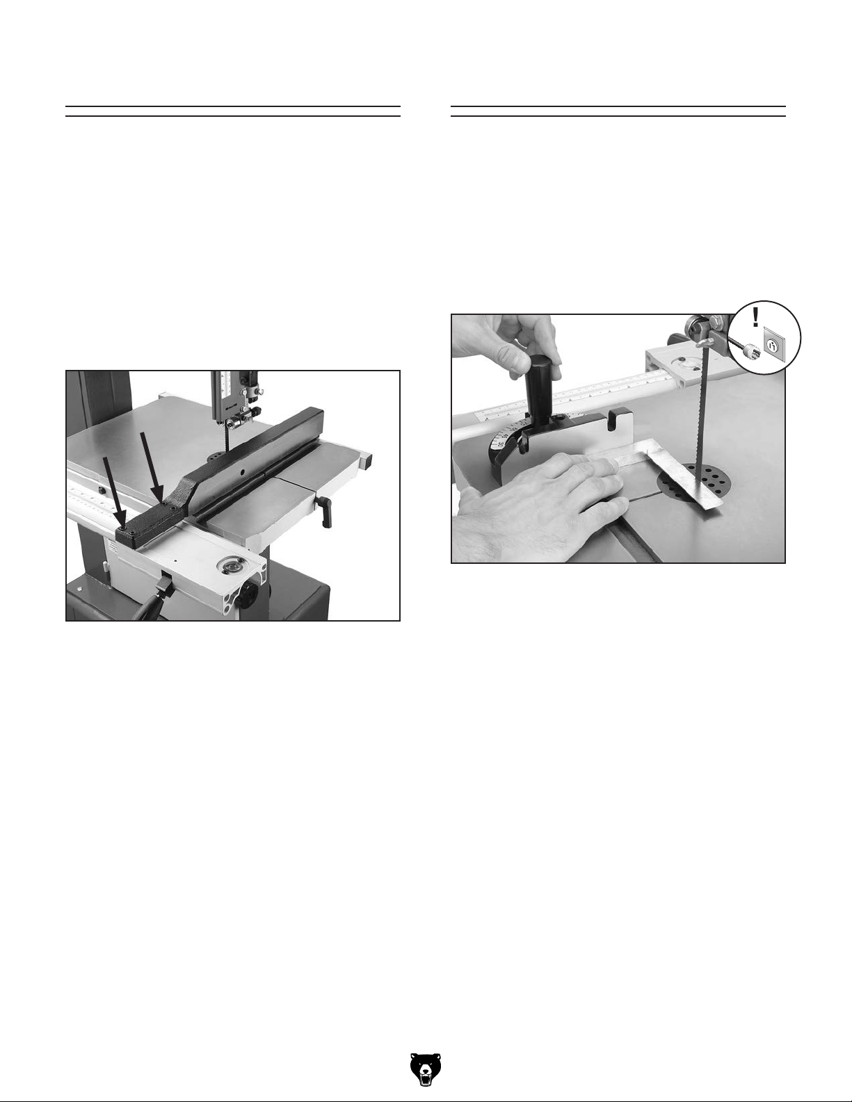
Fence Alignment
Miter Gauge
To ensure cutting accuracy when the fence is first
installed, the fence should be aligned with the
miter slot.
To align the fence parallel with the miter slot:
1. If the fence is mounted on the left-hand side
of the blade, remove it and remount it next to
the miter slot.
2. Loosen the four cap screws located on the
top face of the fence (Figure 28).
The miter gauge needs to be calibrated to the
blade when it is first mounted in the miter slot.
To calibrate the miter gauge:
1. Place one edge of a machinist's square
against the face of the miter gauge and the
other side against the blade face, as shown
in Figure 29.
Figure 28. Four fence cap screws.
3. Adjust the fence face parallel with the edge of
the miter slot.
4. Tighten the four cap screws, being careful not
to move the fence.
Figure 29. Squaring miter gauge to blade.
2. Loosen the lock knob on the miter gauge and
adjust it flush with the edge of the square.
3. Tighten the lock knob, and verify the setting.
Note: Sometimes the tightening procedure
can affect the adjustment.
4. Loosen the screw that secures the angle
pointer and adjust the pointer to the 0˚ mark
on the scale.
5. Retighten the screw that secures the angle
pointer.
G0457 14" Industrial Bandsaw (Mfg. Since 5/11)
-23-
Page 42

Blade Tensioning
A properly tensioned blade is essential for making accurate cuts and is a prerequisite for making
many bandsaw adjustments. The blade tension
scale shows the approximate tension, but the
steps below will allow you to get the optimum tension for the installed blade.
NOTICE
After blade tension and tracking are set correctly, you MUST properly adjust the upper
and lower support bearings and guide-block
assemblies into position before cutting.
Adjusting Support
To tension the bandsaw blade:
1. Make sure you have completed the Test Run
procedure on Page 21 and that the blade is
tracking properly.
2. Raise the upper blade guide assembly as
high as it will go, and adjust the upper and
lower guide blocks as far away from the blade
as possible.
Note: This procedure will NOT work if the
guide blocks have any contact with the
blade.
3. Adjust blade tension until the mark on the
blade tension scale matches the size of the
installed blade.
Note: This scale can only be considered a
general guide. Complete the following steps
to accurately set blade tension.
4. Turn the bandsaw ON.
Bearings
The support bearings are positioned behind
the blade for support during cutting operations.
Proper adjustment of the support bearings is an
important part of making accurate cuts and also
keeps the blade teeth from coming in contact with
the guide bearings while cutting.
To adjust the support bearings:
1. Make sure that the blade is tracking properly
and that it is correctly tensioned.
2. DISCONNECT BANDSAW FROM POWER!
3. Familiarize yourself with the support bearing
controls shown in Figure 30.
Upper Knurled
Knob
Support
Bearing
5. Slowly release the tension one quarter of a
turn at a time. When you see the bandsaw
blade start to flutter, stop decreasing the tension.
6. Now, slowly increase the tension until the
blade stops fluttering, then tighten the tension
another quarter turn.
7. Look at what the tension gauge reads and
use that as a guide for tensioning that blade
in the future.
Note: Always de-tension the blade after use
to increase blade life and reduce strain on the
bandsaw components.
-24-
Thumbscrew
Lock Bolt
Figure 30. Support bearing controls.
G0457 14" Industrial Bandsaw (Mfg. Since 5/11)
Page 43

0.016''
4. Loosen the assembly lock bolt.
5. Rotate the blade guide assembly side-to-
side, until the blade is perpendicular to the
face of the support bearing as illustrated in
Figure 31.
Bandsaw
Blade
Support
Bearing
Note: For a quick gauge, fold a dollar bill in half
twice (four thicknesses of a dollar bill is approximately 0.016") and place it between the support
bearing and the blade as shown in Figure 33.
Top View
Figure 31. Blade should be perpendicular (90˚)
to the face of the support bearing.
6. Tighten the assembly lock bolt.
7. Loosen the thumbscrew on the support bear-
ing adjustment shaft.
8. Place a 0.016" feeler gauge between the
support bearing and the blade, and use the
upper knurled knob to position the bearing
0.016" away from the back of the blade, as
illustrated in Figure 32.
Figure 33. Dollar bill folded twice to make an
approximate 0.016" gauge.
9. Tighten the thumbscrew to keep the support
bearing locked in place.
10. Repeat Steps 4–9 for the lower support bearings.
NOTICE
Whenever changing a blade or adjusting tension and tracking, the upper and lower blade
support bearings and blade guide bearings
must be properly adjusted before cutting
operations.
Side View
Figure 32. Blade should be aligned approxi-
mately 0.016" away from the bearing edge.
G0457 14" Industrial Bandsaw (Mfg. Since 5/11)
-25-
Page 44

Blade Guide
Blade
Guide
Bearing
Blade
Gullets
Adjustments
The blade guides consist of an upper and lower
set of ball bearings that provide side-to-side support to help keep the blade straight while cutting.
The blade guides are designed to be adjusted in
two ways—forward/backward and side-to-side.
To adjust the upper and lower blade guides:
1. Make sure that the blade is tracking properly
and that it is correctly tensioned.
2. DISCONNECT BANDSAW FROM POWER!
3. Familiarize yourself with the blade guide con-
trols shown in Figure 34.
Lower
Knurled
Blade Guide
Bearings
Knob
1
/16"
Figure 35. Lateral adjustment of blade guides.
NOTICE
Make sure that the blade teeth will not contact the guide bearings when the blade is
against the rear support bearing during the
cut or the blade teeth will be ruined.
6. Tighten the thumbscrew on the lateral adjust-
ment rod.
Thumbscrew
Cap Screw
Figure 34. Blade guide controls.
4. Loosen the thumbscrew on the lateral adjust-
ment rod.
5. Rotate the lower knurled knob to position the
blade guides so the edges of the bearings are
1
/16" behind the blade gullets, as illustrated in
Figure 35.
1
Note: The
larger blades it may not be possible. In such
cases, adjust the guide bearings as far forward as possible to the blade gullets, and still
maintain the proper support bearing spacing
adjustment.
/16" spacing is ideal, although with
7. Loosen the cap screws.
8. With the 4mm hex wrench, rotate the center
portion of the blade guide bearings to laterally
position the bearings 0.004" away from the
blade.
Note: 0.004" is approximately the thickness
of a piece of paper.
9. Tighten the cap screw to lock the blade guide
bearings in position.
10. Repeat Steps 4–9 for the lower guides.
NOTICE
Whenever changing a blade or adjusting tension and tracking, the upper and lower blade
support bearings and guide bearings must
be properly adjusted before cutting operations.
-26-
G0457 14" Industrial Bandsaw (Mfg. Since 5/11)
Page 45
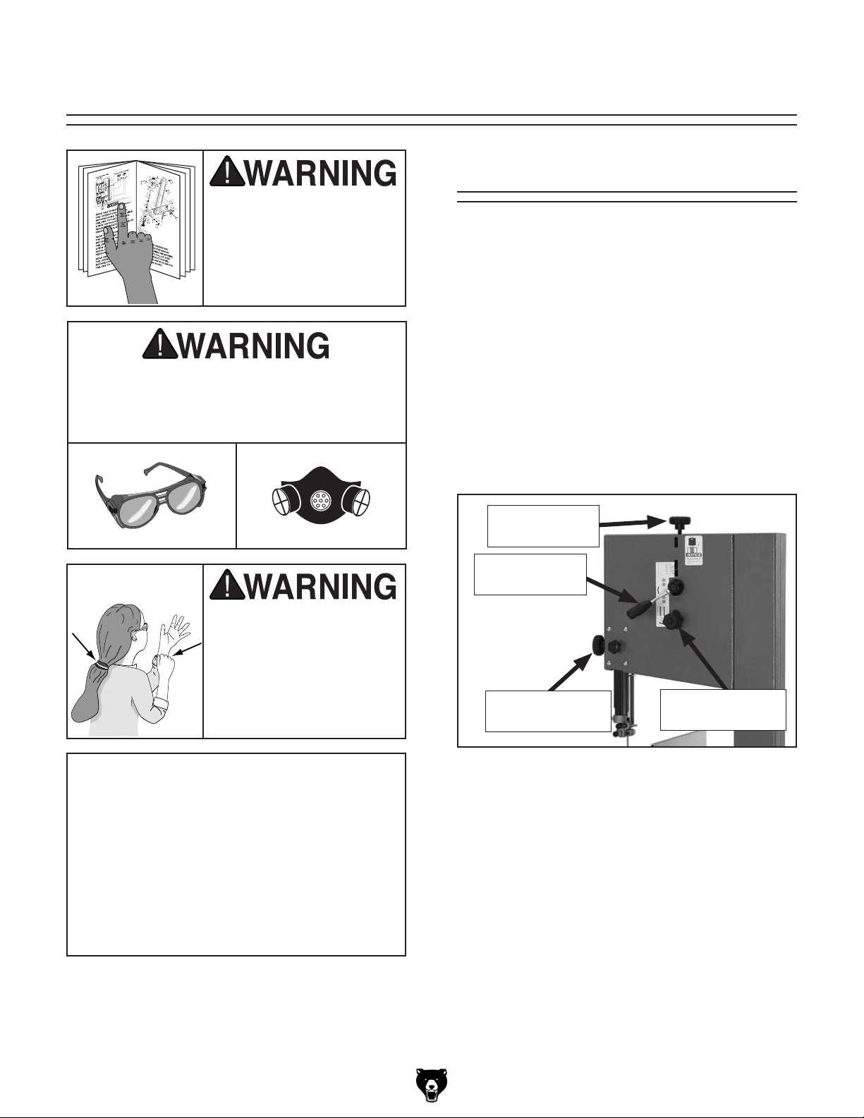
SECTION 4: OPERATIONS
To reduce the risk of
serious injury when using
this machine, read and
understand this entire
manual before beginning
any operations.
Damage to your eyes and lungs could result
from using this machine without proper protective gear. Always wear safety glasses and
a respirator when operating this machine.
Basic Controls
Use the descriptions and figures below to become
familiar with the basic controls of your machine.
Blade Tension Knob: Adjusts the tension on the
blade.
Blade Tension Quick Release: Quickly tensions
or releases the blade without losing its setting.
Blade tracking Adjustment Knob: Adjusts the
blade tracking.
Guide Post Adjustment Knob: Raises and lowers the blade guide post.
Loose hair, clothing, or
jewelry could get caught
in machinery and cause
serious personal injury.
Keep these items away
from moving parts at all
times to reduce this risk.
NOTICE
If you have never used this type of machine
or equipment before, WE STRONGLY RECOMMEND that you read books, review
industry trade magazines, or get formal
training before beginning any projects.
Regardless of the content in this section,
Grizzly Industrial will not be held liable for
accidents caused by lack of training.
Blade Tension
Knob
Blade Tension
Quick Release
Guide Post
Adjustment Knob
Figure 36. Basic controls (rear).
Blade Tracking
Adjustment Knob
G0457 14" Industrial Bandsaw (Mfg. Since 5/11)
-27-
Page 46

ON/OFF Switch: Starts and stops the blade
motor.
Overview
Miter Gauge Lock Handle: Locks the miter
gauge at the current setting.
Fence Lock Lever: Locks the fence at its current
position.
Miter Gauge Lock
Handle
ON/OFF Switch
Fence Lock Lever
Figure 37. Basic controls (front).
The bandsaw is one of the most versatile wood
cutting tools in the shop. It is capable of performing many different cutting functions, including:
Straight Cuts
• Miters
• Angles
• Compound Angles
• Resawing
• Ripping
• Crosscutting
Irregular Cuts
• Simple and Complex Curves
• Duplicate Parts
• Circles
• Beveled Curves
A properly adjusted and tuned bandsaw can be
safer to operate than most other saws and performs many functions with ease and accuracy.
Basic Cutting Tips
Here are some basic tips to follow when operating the bandsaw:
• Replace, sharpen, and clean blades as necessary and make adjustments periodically to
keep the saw running in top condition.
• Use light and even pressure while cutting.
Light contact with the blade will permit easier
line following and prevent undue friction.
• Avoid trying to turn tight corners because this
will twist the blade. Remember, you must saw
around corners.
• Misuse of the saw or using incorrect techniques is unsafe and results in frustration and
poor cuts. Remember—the blade does the
cutting with the operator’s guidance.
-28-
G0457 14" Industrial Bandsaw (Mfg. Since 5/11)
Page 47

Inspection
Some wood workpieces are not safe to cut or may
require modification before they are safe to cut.
Before making cuts, get in the habit of inspecting all workpieces for the following:
Table TiltWorkpiece
The bandsaw table will tilt 8˚ left and 45˚ right to
provide a wide range of cutting options. Most cutting operations are done at 90° and rarely will the
table need to be tilted left. Remove the positive
stop bolt to tilt the table to the left.
To tilt the table:
• Material Type: This machine is intended for
cutting natural and man-made wood products, laminate covered wood products, and
some plastics. Cutting drywall or cementitious backer board creates extremely fine
dust and may reduce the life of the bearings.
This machine is NOT designed to cut metal,
glass, stone, tile, etc.; cutting these materials
with this saw may lead to injury.
• Foreign Objects: Nails, staples, dirt, rocks
and other foreign objects are often embedded in wood. While cutting, these objects can
become dislodged and hit the operator or
break the blade, which might then fly apart.
Always visually inspect your workpiece for
these items. If they cannot be removed, do
NOT cut the workpiece.
• Large/Loose Knots: Loose knots can
become dislodged during the cutting operation. Large knots can cause blade damage.
Choose workpieces that do not have large/
loose knots or plan ahead to avoid cutting
through them.
1. Loosen the two table trunnion hand knobs.
2. Position the table to the desired angle of tilt.
Refer to the angle gauge on the front table
trunnion for the tilting angle.
3. Retighten both table trunnion hand knobs.
• Wet or "Green" Stock: Cutting wood with
a moisture content over 20% causes unnecessary wear on the blade and yields poor
results.
• Excessive Warping: Workpieces with excessive cupping, bowing, or twisting are dangerous to cut because they are unstable and can
move unpredictably when being cut. DO NOT
use workpieces with these characteristics!
• Minor Warping: Workpieces with slight cupping can be safely supported if the cupped
side faces the table or fence. On the contrary,
a workpiece supported on the bowed side will
rock during a cut, leading to loss of control.
G0457 14" Industrial Bandsaw (Mfg. Since 5/11)
-29-
Page 48

Guide Post
Ripping
The guide post, shown in Figure 38, connects
the upper blade guide assembly to the bandsaw.
The guide post allows the blade guide assembly
to move up or down via a rack and pinion. In order
to cut accurately, the blade guide assembly must
be no more than 1" from the top of the workpiece
at all times—this positioning provides the greatest
support to the blade.
Adjustment
Knob
Lock
Knob
Guide Post
Ripping is the process of cutting with the grain of
the wood stock. For plywood and other processed
wood, ripping simply means cutting down the
length of the workpiece.
To rip with the Model G0457:
1. Adjust the fence to match the width of the
cut on your workpiece and lock the fence in
place.
2. Make sure the bandsaw is properly set up
and adjusted as described in SECTION 3:
SETUP.
3. Slowly feed the workpiece into the blade
and continue with the cut until the blade is
completely through the workpiece. Figure 39
shows a typical ripping operation.
Note: If you are cutting narrow pieces, use a
push stick to protect your fingers.
Figure 38. Guide post controls.
To adjust guide post:
1. Make sure that the blade tension, blade
tracking, support bearing, and blade guides
are adjusted correctly.
2. Loosen the guide post lock knob shown in
Figure 38.
3. Raise/lower the guide post with the adjust-
ment knob to within 1" from the top of the
workpiece to the bottom of the blade guide
assembly.
4. Lock the guide post in place with the lock
knob.
Figure 39. Ripping with a push stick.
NEVER place fingers or hands in the line of
cut. In the event that something unexpected
happens, your hands or fingers may be
pulled into the blade. ALWAYS use a push
stick when ripping narrow pieces. Failure to
follow these warnings may result in serious
personal injury!
-30-
G0457 14" Industrial Bandsaw (Mfg. Since 5/11)
Page 49
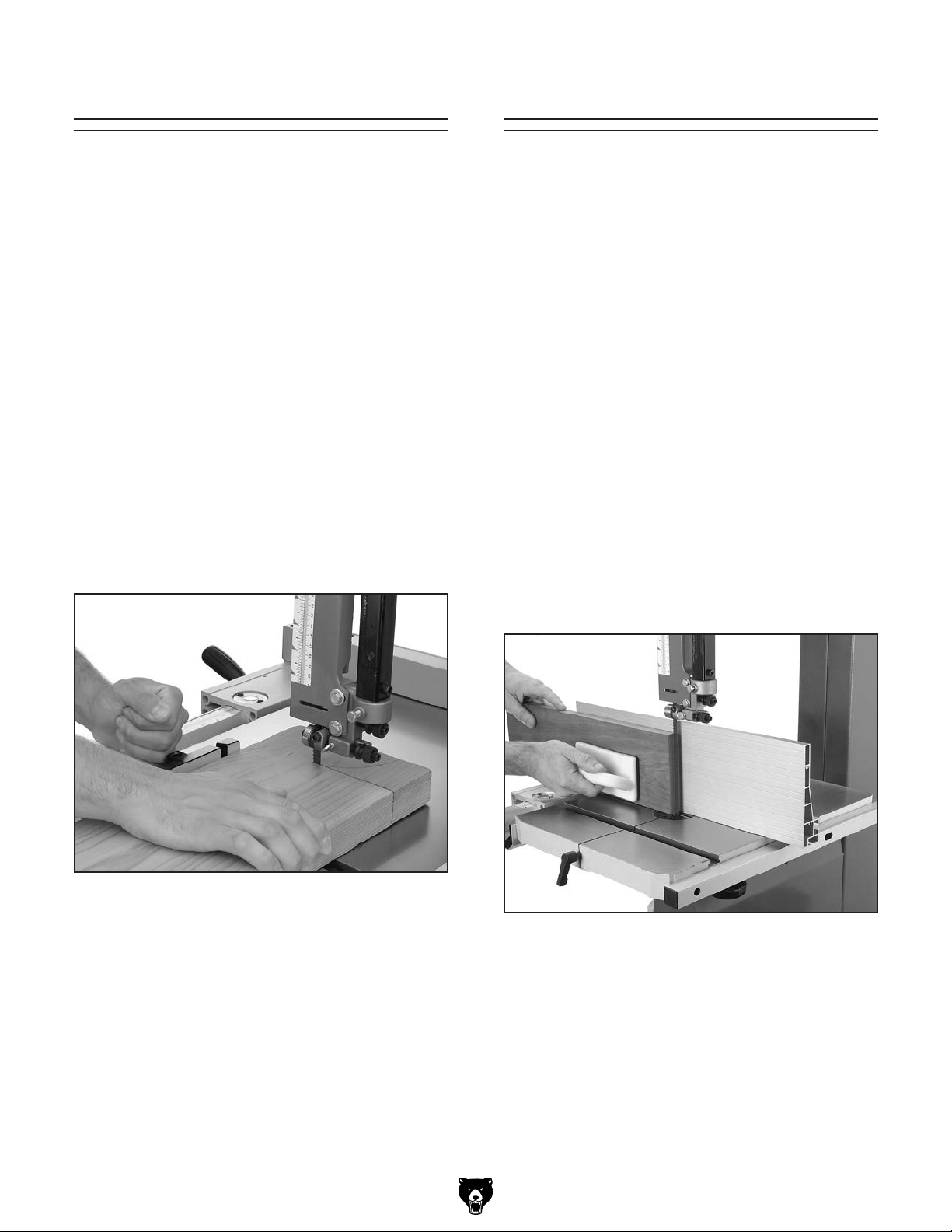
Crosscutting
Resawing
Crosscutting is the process of cutting across the
grain of wood. For plywood and other processed
wood, crosscutting simply means cutting across
the width of the material.
To crosscut with the Model G0457:
1. Mark the workpiece on the edge where you
want to begin the cut.
2. Move the fence out of the way. Place the
workpiece evenly against the miter gauge.
3. Line up the mark with the blade.
4. After all safety precautions have been met,
turn the bandsaw ON. Slowly feed the
workpiece into the blade and continue the
cut until the blade is all the way through the
workpiece. Figure 40 shows a typical crosscutting operation.
Resawing (Figure 41) is the process of cutting a
board into two or more thinner boards. The maximum board width that can be resawn is limited
by the maximum cutting height of the bandsaw.
Maximum cutting height for this bandsaw is 10".
The Model G0457 14" Industrial Bandsaw is
capable of resawing, provided the saw is properly
set up. Attempting to resaw too wide or too dense
of a board may put excessive strain on the blade
and cause breakage.
One of the most important considerations when
resawing is blade selection. Generally, the wider
blade, the better. In most applications, a hook or
a skip tooth style will be desirable. Also, since
most resawn lumber will be planed smooth, you
should choose blades with fewer teeth-per-inch
(from 3 to 6). While blades with fewer teeth-perinch produce rougher cuts, these types of blades
offer larger gullet capacities for clearing sawdust,
reducing heat buildup and reducing strain on the
motor.
Figure 40. Crosscutting with miter gauge.
G0457 14" Industrial Bandsaw (Mfg. Since 5/11)
Figure 41. Resawing lumber.
-31-
Page 50

To resaw a workpiece:
1. Verify that the bandsaw is set up properly and
that the table is perpendicular to the blade.
2. Use the widest blade your bandsaw will
accept.
Note: The blade must also be sharp and
clean.
3. Use a fence to guide the workpiece.
4. Set your fence to the desired width of cut and
lock it in place.
5. Support the ends of the board if necessary.
6. Turn the bandsaw ON.
7. Using push paddles and a push stick, keep
pressure against the fence and table, and
slowly feed the workpiece into the moving
blade until the blade is completely through
the workpiece.
Cutting Curves
When cutting curves, simultaneously feed and
turn the stock carefully so that the blade follows
the layout line without twisting. If a curve is so
abrupt that it is necessary to repeatedly back up
and cut a new kerf, use either a narrower blade
or a blade with more TPI (teeth per inch), or make
more relief cuts.
Always make short cuts first, then proceed to
the longer cuts. Relief cuts will also reduce the
chance that the blade will be pinched or twisted.
Relief cuts are cuts made through the waste
portion of the workpiece and are stopped at the
layout line. As you cut along the layout line, waste
wood is released from the workpiece, alleviating
any pressure on the back of the blade. Relief cuts
also make backing the workpiece out easier, if
needed.
NOTICE
The list below displays blade widths and
the corresponding minimum radii each size
of blade for the Model G0457.
Width Radius
1
⁄8" ....................................1⁄8"
3
⁄16" ...................................3⁄8"
1
⁄4'' ....................................5⁄8''
3
⁄8'' .................................... 11⁄4''
1
⁄2'' .................................... 21⁄2''
5
⁄8'' .................................... 33⁄4''
3
⁄4'' .................................... 51⁄2''
-32-
G0457 14" Industrial Bandsaw (Mfg. Since 5/11)
Page 51
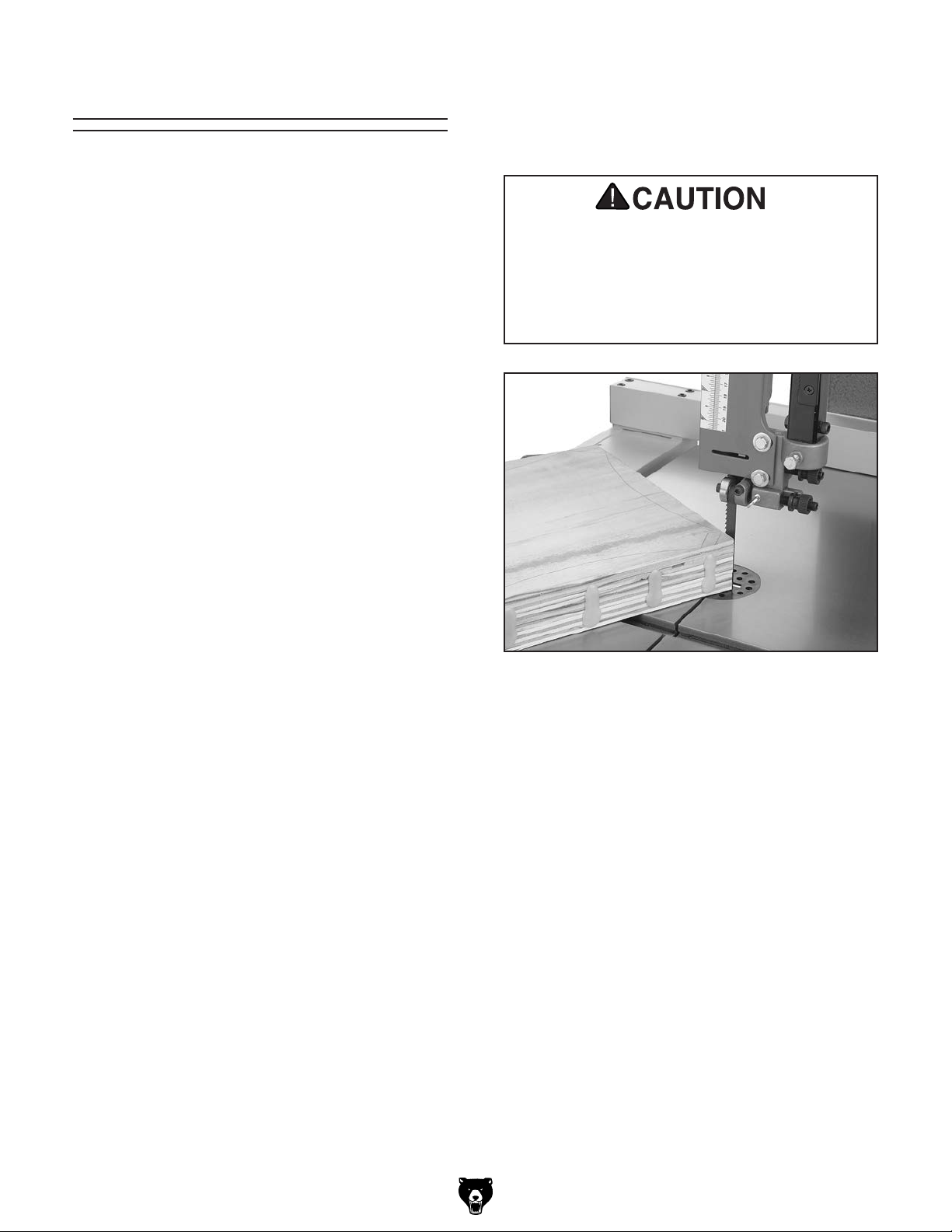
Stacked Cuts
One of the benefits of a bandsaw is its ability to
cut multiple copies of a particular shape by stacking a number of workpieces together.
5. Cut the stack of pieces as though you were
cutting a single piece. Follow your layout line
with the blade kerf on the waste side of your
line as shown in Figure 42.
Before making stacked cuts, ensure that both the
table and the blade are properly adjusted to 90°.
Otherwise, any error will be compounded with
each piece cut from the top to the bottom of the
stack.
To complete a stacked cut:
1. Align your pieces from top to bottom to
ensure that each piece has adequate scrap
to provide a clean, unhampered cut.
2. Secure all the pieces together in a manner
that will not interfere with the cutting. Hot glue
on the edges works well, as do brad nails
through the waste portion. (Be careful not to
cut into the brads!)
3. On the face of the top piece, lay out the
shape you intend to cut.
4. Make relief cuts perpendicular to the outline of your intended shape in areas where
changes in blade direction could strain the
woodgrain or cause the blade kerf to bind.
Cutting into brad nails that are used to
secure the multiple pieces can cause the
blade to break and may cause an injury to
the operator. Be extremely careful of where
you are cutting when performing this operation.
Figure 42. Cutting multiple pieces at once.
G0457 14" Industrial Bandsaw (Mfg. Since 5/11)
-33-
Page 52

Blade Information
Blade Width
Cutting Radius
Selecting the right blade requires a knowledge
of the various blade characteristics mentioned
below, the type of material you plan to cut, and the
type of cut you are going to perform.
Blade Length
Measured by the circumference, blade lengths
are usually unique to the brand of your bandsaw
and the distance between wheels. The Model
G0457 is designed for blades that are 106" long.
Refer to the current Grizzly catalog for prices and
ordering information.
Blade Width
Measured from the back of the blade to the tip of
the blade tooth (the widest point), blade width is
often the first consideration given to blade selection. Blade width dictates the largest and smallest
curve that can be cut, as well as how accurately it
can cut a straight line.
1
The Model G0457 can use blades from
in width. Always pick the size of blade that best
suits your application.
⁄8" to 3⁄4"
• Straight Cutting: Use the largest width
blade that you own. The Model G0457 will
accept blades up to
can cut tight curves (a small radius) but
are not very good at cutting straight lines
because they naturally wander (blade lead).
However, larger blades are much better at
cutting straight lines, but function poorly at
cutting small curves because of their size.
3
⁄4" wide. Narrow blades
Tooth Style
When selecting blades, another option to consider is the shape, gullet size, teeth set and teeth
angle—otherwise known as “Tooth Style.”
Figure 44 shows the three main categories of
tooth style:
Raker Skip Hook
• Curve Cutting: Use the chart in Figure 43 to
determine the correct blade for curve cutting.
Determine the smallest radius curve that will
be cut on your workpiece and use the corresponding blade width.
Figure 43. Blade width radii.
Figure 44. Raker, Skip & Hook tooth styles.
• Raker: This style is considered to be the
standard because the tooth size and shape
are the same as the tooth gullet. The teeth
on raker blades usually are very numerous,
have no angle, and produce cuts by scraping the material; these characteristics result
in very smooth cuts, but do not cut fast and
generate more heat while cutting.
• Skip: This style is similar to a raker blade
that is missing every other tooth. Because
of the design, skip toothed blades have a
much larger gullet than raker blades, and
therefore, cut faster and generate more heat.
However, these blades also leave a rougher
cut than raker blades.
-34-
G0457 14" Industrial Bandsaw (Mfg. Since 5/11)
Page 53

• Hook: The teeth on this style have a positive angle (downward) which makes them
dig into the material, and the gullets are usually rounded for easier waste removal. These
blades are excellent for the tough demands
of resawing and ripping thick material.
The most common causes of blade breakage
are:
• Aligning or adjusting the guides incorrectly.
• Forcing or twisting a wide blade around a
curve of short radius.
Tooth Pitch
Usually measured as TPI (teeth per inch), tooth
pitch determines the size of the teeth. More teeth
per inch (fine pitch) will cut slower, but smoother;
while fewer teeth per inch (coarse pitch) will cut
rougher, but faster. As a general rule, choose
blades that will have at least three teeth in the
material at all times. Use fine pitched blades on
harder woods and coarse pitched blades on softer
woods.
Blade Care
A bandsaw blade is a delicate piece of steel that
is subjected to tremendous strain. You can obtain
longer use from a bandsaw blade if you give it fair
treatment and always use the appropriate feed
rate for your operation.
Be sure to select blades with the proper width,
style, and pitch for each application. The wrong
choice of blades will often produce unnecessary
heat which will shorten the life of your blade.
• Feeding the workpiece into the blade too
fast.
• Using a blade with dull teeth or the absence
of sufficient set.
• Incorrect tension.
• Setting the top blade guide assembly set too
high above the work piece.
• Using a blade with a lumpy or improperly finished braze or weld.
• Continuously running the bandsaw when not
in use.
A clean blade will perform much better than a dirty
blade. Dirty or gummed up blades pass through
the cutting material with much more resistance
than clean blades. This extra resistance also
causes unnecessary heat.
Blade Breakage
Many conditions may cause a bandsaw blade to
break. Blade breakage is unavoidable, in some
cases, since it is the natural result of the peculiar
stresses that bandsaw blades are subjected to.
Blade breakage is also due to avoidable circumstances. Avoidable breakage is most often the
result of poor care or judgement on the part of the
operator when mounting or adjusting the blade or
support guides.
G0457 14" Industrial Bandsaw (Mfg. Since 5/11)
-35-
Page 54

Blade Changes
To replace the blade:
1. Slide the blade through the table slot, ensur-
ing that the teeth are pointing down toward
the table.
Always disconnect power
to the machine when
changing blades. Failure
to do this may result in
serious personal injury.
All saw blades are dangerous and may cause
personal injury. To reduce
the risk of being injured,
wear leather gloves when
handling saw blades.
To remove the blade:
1. DISCONNECT BANDSAW FROM POWER!
2. Release the blade tension by turning the
blade tension quick release lever to the left.
Note: If the teeth will not point downward in
any orientation, the blade is inside-out. Put
on heavy gloves, remove the blade, and twist
it right side-out.
2. Slip the blade through the guides, and mount
it on the upper and lower wheels (Figure
45).
3. Remove the table insert and the table pin.
Adjust the upper and lower guide bearings as
far away as possible from the blade.
4. Open the upper and lower wheel covers, and
with gloved hands, slide the blade off both
wheels.
5. Rotate the blade 90˚ and slide it through the
slot in the table.
Figure 45. Placing blade on the wheels.
3. Tighten the blade tension quick release.
4. Apply tension to the blade by turning the ten-
sion control knob. Rotate the upper wheel
slowly by hand as tension is applied to allow
the blade to center itself on the wheel. Adjust
tracking if needed.
5. Adjust tension as described Page 24.
6. Adjust the upper/lower guide bearings and
the support bearings.
7. Close the wheel covers.
8. Replace the table insert and table pin, being
sure not to use excessive force when inserting the table pin.
-36-
G0457 14" Industrial Bandsaw (Mfg. Since 5/11)
Page 55
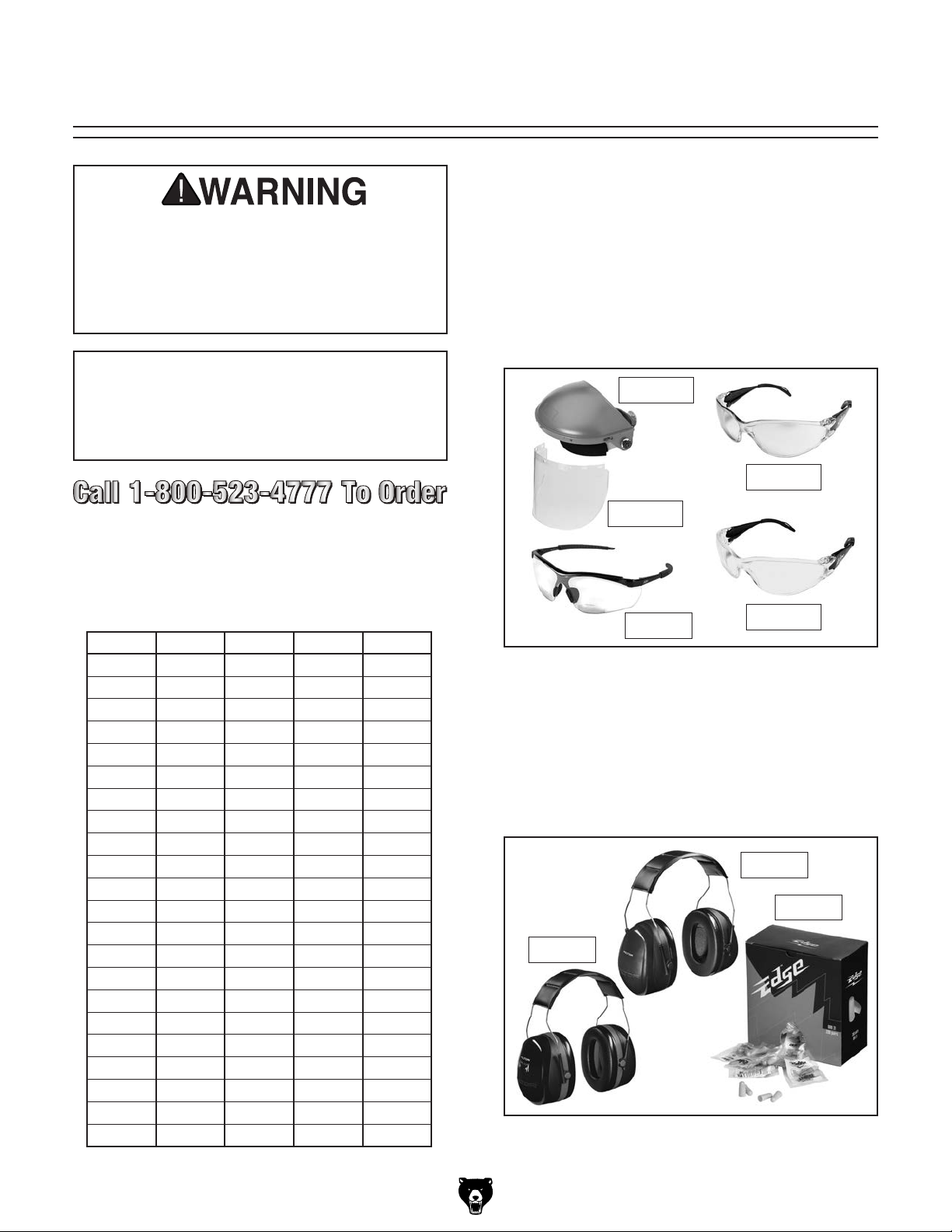
ACCESSORIES
SECTION 5: ACCESSORIES
Some aftermarket accessories can be
installed on this machine that could cause
it to function improperly, increasing the risk
of serious personal injury. To minimize this
risk, only install accessories recommended
for this machine by Grizzly.
Basic Eye Protection
T20501—Face Shield Crown Protector 4"
T20502—Face Shield Crown Protector 7"
T20503—Face Shield Window
T20451—“Kirova” Clear Safety Glasses
T20452—“Kirova” Anti-Reflective S. Glasses
H7194—Bifocal Safety Glasses 1.5
H7195—Bifocal Safety Glasses 2.0
H7196—Bifocal Safety Glasses 2.5
NOTICE
Refer to the newest copy of the Grizzly
Catalog for other accessories available for
this machine.
Replacement Blades
These 106" long replacement blades are milled
for exact tooth set and are made with high quality
tool steel.
MODEL WIDTH GAUGE TPI STYLE
G6638
G6639
G6640
G6641
G6642
G6643
G6644
G6645
G6646
G6647
G6648
G6649
G6650
G6651
G6652
G6653
G6654
G6655
G6656
G6657
G6658
G6659
1
⁄8" .035 14 Raker
1
⁄8" .035 18 Raker
3
⁄16" .035 4 Skip
3
⁄16" .035 10 Raker
3
⁄16" .035 14 Raker
1
⁄4" .035 4 Hook
1
⁄4" .035 6 Hook
1
⁄4" .035 10 Raker
1
⁄4" .035 14 Raker
1
⁄4" .035 18 Raker
3
⁄8" .035 4 Hook
3
⁄8" .035 6 Hook
3
⁄8" .035 10 Raker
3
⁄8" .035 14 Raker
1
⁄2" .035 3 Hook
1
⁄2" .035 4 Hook
1
⁄2" .035 6 Hook
1
⁄2" .035 10 Raker
1
⁄2" .035 14 Raker
3
⁄4" .035 3 Hook
3
⁄4" .035 6 Hook
3
⁄4" .035 10 Raker
T20502
T20452
T20503
H7194
T20451
Figure 46. Assortment of basic eye protection.
H4978—Deluxe Earmuffs - 27dB
H4979—Twin Cup Hearing Protector - 29dB
H4977—Work-Tunes Radio Earmuffs - 25dB
Protect yourself comfortably with a pair of cushioned earmuffs. Especially important if you or
employees operate for hours at a time.
H4978
H4977
H4979
Figure 47. Our most popular earmuffs.
G0457 14" Industrial Bandsaw (Mfg. Since 5/11)
-37-
Page 56

T20514—Small Half-Mask Respirator
T20515—Medium Half-Mask Respirator
T20516—Large Half-Mask Respirator
T20511—Pre-Filter P100
T20539—Cartridge Filter 2PK P100
T20541—Cartridge Filter 2PK P100 & O Vapor
Wood and other types of dust can cause severe
respiratory damage. If you work around dust everyday, a half-mask respirator can greatly reduce
your risk. Compatible with safety glasses!
Figure 48. Half-mask respirator with disposable
cartridge filters.
H5408—Blade Tensioning Gauge
The Blade Tensioning Gauge ensures long blade
life, reduced blade breakage, and straight cutting
by indicating correct tension. A precision dial indicator provides you with a direct readout in PSI.
The Blade Tensioning Gauge is made of lightweight, cast aluminum for optimum accuracy.
Bright color coding makes it easy to use and easy
to read. The Blade Tensioning Gauge comes in a
handy metal box with instructions on the lid.
G5562—SLIPIT
G5563—SLIPIT
G2871—Boeshield
G2870—Boeshield
H3788—G96
H3789—G96
®
1 Qt. Gel
®
12 oz Spray
®
T-9 12 oz Spray
®
®
Gun Treatment 12 oz Spray
®
Gun Treatment 4.5 oz Spray
T-9 4 oz Spray
Figure 49. Recommended products for protect-
ing unpainted cast iron/steel part on machinery.
Figure 50. H5408 Blade Tensioning Gauge.
G7314—Heavy-Duty SHOP FOX
®
Mobile Base
Make your machine mobile with this popular
patented mobile base. The unique outrigger type
supports increase stability and lower machine
height. This heavy duty mobile base is rated for
up to a 600 lb. capacity.
-38-
Figure 51. G7314 SHOP FOX® Mobile Base.
G0457 14" Industrial Bandsaw (Mfg. Since 5/11)
Page 57

G1928—Bandsaw Handbook
This is the bandsaw bible. Covers step-by-step
instructions for basic/advanced cutting techniques. Also includes advanced maintenance,
service and troubleshooting procedures, as well
as information on bandsaw history/design and
blade metallurgy. 320 pages.
Figure 52. Bandsaw handbook.
G9256—6" Dial Caliper
G9257—8" Dial Caliper
G9258—12" Dial Caliper
These traditional dial calipers are accurate to
0.001" and can measure outside surfaces, inside
surfaces, and heights/depths. Features stainless
steel, shock resistant construction and a dust
proof display. An absolute treat for the perfectionist!
G8983—Tilting Roller Stand
Adjusts from 26" to 44", 0º-45º. 150 lb. capacity.
G8984—Single Roller Stand
5
Adjusts from 26
⁄8" to 45". 250 lb. capacity.
G8985—5 Roller Stand
5
Adjusts from 26" to 44
⁄8". 250 lb. capacity.
These super heavy-duty roller stands feature convenient hand knobs for fast height adjustment.
G8983
G8985
G8984
®
Figure 54. SHOP FOX
Roller Stands.
G5683— Magnetic Base Light
Light up your work just where you need it. Flexible
neck lamp features magnetic base that attaches
with the twist of a switch so you can use it on
every machine. 110V. Maximum 60 watt bulb.
Figure 53. Grizzly® Dial Calipers.
G0457 14" Industrial Bandsaw (Mfg. Since 5/11)
Figure 55. Magnetic Base Light.
-39-
Page 58

SECTION 6: MAINTENANCE
Unpainted Cast Iron
Always disconnect power
to the machine before
performing maintenance.
Failure to do this may
result in serious personal injury.
Protect the unpainted cast iron surfaces on the
table by wiping the table clean after every use—
this ensures moisture from wood dust does not
remain on bare metal surfaces.
Schedule
For optimum performance from your machine,
follow this maintenance schedule and refer to any
specific instructions given in this section.
Daily Check:
• Loose mounting bolts.
• Damaged saw blade.
• Worn or damaged wires.
• Any other unsafe condition.
Monthly Check:
• V-belt tension, damage, or wear.
• Clean/vacuum dust buildup from inside cabinet and off motor.
Cleaning
Keep tables rust-free with regular applications of
products like G96
Boeshield
Page 37 for more details).
®
T-9 (see Section 5: Accessories on
®
Gun Treatment, SLIPIT®, or
Lubrication
Sealed and pre-lubricated ball bearings require
no lubrication for the life of the bearings. All bearings are standard sizes, and replacements can be
purchased from our parts department or bearing
supply store.
For adjustment controls, an occasional “shot” of
light oil is all that is necessary. Wipe off any sawdust with a clean cloth, towel or dry paint brush,
and spray on the lubricant. Do not get oil on the
pulleys or V-belt because it could cause belt deterioration and slipping.
Cleaning the Model G0457 is relatively easy.
Vacuum excess wood chips and sawdust, and
wipe off the remaining dust with a dry cloth. If any
resin has built up, use a resin dissolving cleaner
to remove it. Treat all unpainted cast iron and steel
with a non-staining lubricant after cleaning.
-40-
G0457 14" Industrial Bandsaw (Mfg. Since 5/11)
Page 59

Guide Post
1. DISCONNECT BANDSAW FROM POWER!
Blade Tension Leadscrew
1. DISCONNECT BANDSAW FROM POWER!
2. Open the upper wheel cover, then lower
the guide post so the upper guide bearings
almost touch the table.
3. Wipe the old grease off the rack (the long
plate with teeth). The old grease will be
contaminated with sawdust, so you want to
remove as much of it as possible (Figure
56).
Guide
Adjustment
Knob
Rack
Guide Post
2. Open the upper wheel cover, then wipe as
much of the old grease off the blade tension
leadscrew as possible. The old grease will
be contaminated with sawdust, so you want
to remove as much of it as possible (Figure
36).
Blade Tension
Leadscrew
Figure 57. Blade tension leadscrew.
Figure 56. Guide post rack lubrication.
4. Use mineral spirits or degreaser to clean any
remaining grease from the rack. Make sure to
thoroughly wipe off the degreaser or mineral
spirits after use so they won't contaminate
the new grease.
5. Use a small, clean brush to apply NLGI#2 or
equivalent automotive-grade multi-purpose
grease to the rack. After applying, rotate the
guide adjustment knob several times to distribute the grease.
6. Close the upper wheel cover, and re-adjust
the guide post height as necessary.
3. Use mineral spirits or degreaser to clean any
remaining grease from the leadscrew. Make
sure to thoroughly wipe off the degreaser or
mineral spirits after use so they will not contaminate the new grease.
4. Use a small, clean brush to apply NLGI#2 or
equivalent automotive-grade multi-purpose
grease to the leadscrew. After applying,
rotate the blade tension knob through its full
range of motion to distribute the grease.
5. Close the upper wheel cover, and re-adjust
the blade and belt tension as necessary.
G0457 14" Industrial Bandsaw (Mfg. Since 5/11)
-41-
Page 60
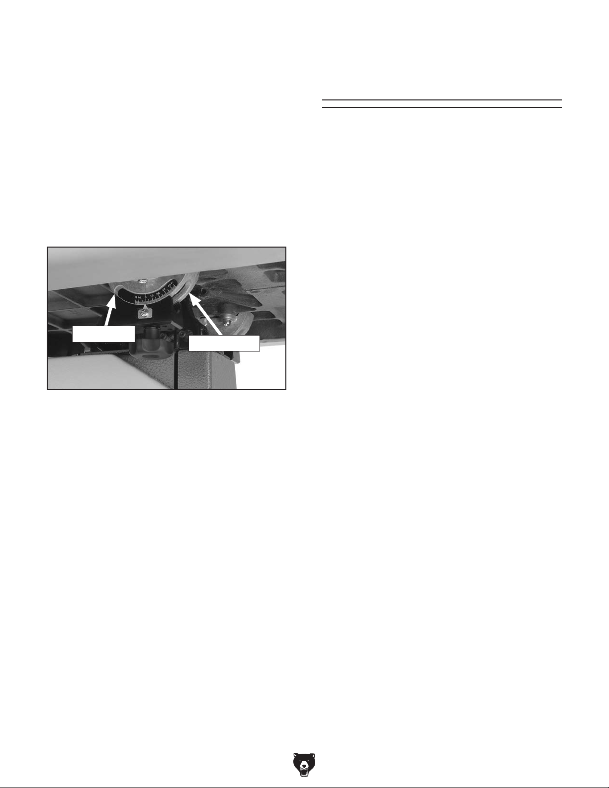
Table Trunnions
1. DISCONNECT BANDSAW FROM POWER!
2. Wipe the old grease off the bearing surfaces
of the table trunnions. Start with the outward
side of the table trunnions (Figure 58) when
the table is at 0°, then tilt the table to 45° and
wipe off the inward side. The old grease will
be contaminated with sawdust, so you want
to remove as much of it as you can.
Note: For easiest access to the trunnions and
the best cleaning results, consider removing
the table during this procedure.
Redressing Rubber
Tires
As the bandsaw ages, the rubber tires on the
wheels may need to be redressed if they harden or
glaze over. Redressing the rubber tires improves
blade tracking and reduces vibration/blade lead.
If the rubber tires become too worn, then blade
tracking will become extremely difficult. At that
point, redressing will no longer be effective and
the rubber tires must be replaced.
To redress the rubber tires:
1. DISCONNECT BANDSAW FROM POWER!
2. Put on heavy leather gloves.
Inward Side
Outward Side
Figure 58. Sides of table trunnions to grease.
3. Use mineral spirits or degreaser to clean any
remaining grease from the trunnions. Make
sure to thoroughly wipe off the degreaser or
mineral spirits after use so they won't contaminate the new grease.
4. Use a small, clean brush to apply NLGI#2 or
equivalent automotive-grade multi-purpose
grease to the trunnion bearing surfaces. After
applying, tilt the table back and forth from 0°
to 45° to distribute the grease.
3. Remove the blade.
4. Clean any built-up sawdust from the rubber
tires.
5. Hold 100 grit sandpaper against the rubber tire and rotate the wheel by hand. Only
redress the rubber enough to expose a fresh
rubber surface.
-42-
G0457 14" Industrial Bandsaw (Mfg. Since 5/11)
Page 61
SECTION 7: SERVICE
Review the troubleshooting and procedures in this section to fix or adjust your machine if a problem develops. If you need replacement parts or you are unsure of your repair skills, then feel free to call our Technical
Support at (570) 546-9663.
Troubleshooting
Motor & Electrical
Symptom Possible Cause Possible Solution
Machine does
not start or a
breaker trips.
Machine
stalls or is
underpowered.
1. Plug/receptacle is at fault or wired incorrectly.
2. Motor connection wired incorrectly.
3. Power supply is at fault/switched OFF.
4. Motor ON/OFF switch is at fault.
5. Wiring is open/has high resistance.
6. Start capacitor is at fault.
7. Motor is at fault.
1. Wrong workpiece material (wood).
2. Processing speed too fast for task.
3. Low power supply voltage.
4. Run capacitor is at fault.
5. V-belt slipping.
6. Plug/receptacle is at fault.
7. Motor connection is wired incorrectly.
8. Blade is slipping on wheels.
9. Motor bearings are at fault.
10. Motor has overheated.
11. Motor is at fault.
1. Test for good contact or correct the wiring.
2. Correct motor wiring connections (Page 51).
3. Ensure hot lines have correct voltage on all legs and
main power supply is switched ON.
4. Replace faulty ON/OFF switch.
5. Check for broken wires or corroded/disconnected
connections, and repair/replace as necessary.
6. Test/replace if faulty.
7. Repair/replace.
1. Use wood with correct moisture content, without glues,
and little pitch/resins.
2. Decrease processing speed. See Basic Cutting Tips
on Page 28.
3. Ensure all hot lines have correct voltage on all legs.
4. Repair/replace.
5. Replace bad V-belt, align pulleys, and re-tension
(Page 46).
6. Test for good contacts and correct wiring.
7. Correct motor wiring connections (Page 51).
8. Adjust blade tracking (Page 20) and tension (Page 24)
to factory specifications.
9. Test by rotating shaft; rotational grinding/loose shaft
requires bearing replacement.
10. Clean off motor, let cool, and reduce workload.
11. Repair/replace.
G0457 14" Industrial Bandsaw (Mfg. Since 5/11)
-43-
Page 62

Symptom Possible Cause Possible Solution
Machine has
vibration or
noisy operation
when running.
1. Motor or component is loose.
2. V-belt worn or loose.
3. Motor fan is rubbing on fan cover.
4. Pulley is loose.
5. Machine is incorrectly mounted or sits unevenly
on floor.
6. Motor bearings are at fault.
7. Blade weld is at fault or teeth are broken.
8. Worn arbor bearings.
9. Wheels not coplanar/aligned correctly.
10. Tires incorrectly installed.
11. Bent or worn out blade.
12. Wheels out of balance.
1. Inspect/replace stripped or damaged bolts/nuts, and
re-tighten with thread locking fluid.
2. Inspect/replace belt (Page 46).
3. Replace dented fan cover and loose/damaged fan.
4. Realign/replace shaft, pulley, set screw, and key as
required.
5. Adjust the feet on the bottom of the stand; relocate
machine.
6. Test by rotating shaft — rotational grinding/loose shaft
requires bearing replacement.
7. Replace blade (Page 36).
8. Check/replace arbor bearings.
9. Adjust wheel alignment to coplaner (Page 49).
10. Re-install tires.
11. Replace blade (Page 36).
12. Replace wheels.
Cutting Operations
Symptom Possible Cause Possible Solution
Machine slows
when operating.
Ticking sound
when the saw is
running.
1. Applying too much pressure to workpiece.
2. Blade is dull.
1. Blade weld contacting support bearing.
2. Blade weld may be failing.
1. Feed workpiece slower. See Basic Cutting Tips on
Page 28.
2. Replace blade (Page 36).
1. Use file or stone to smooth and round the back of the
blade.
2. Inspect and replace blade if necessary (Page 36).
Blade contacting
table insert.
Vibration when
cutting.
Burn marks on
the edge of the
cut.
Rough or poor
quality cuts.
Sawdust buildup
inside cabinet.
Blade wanders or
won't follow line
of cut.
1. Excessive side pressure when cutting.
2. Table improperly adjusted.
1. Loose or damaged blade. 1. Tighten or replace blade. See Page 24 or 36.
1. Too much side pressure when feeding
workpiece.
2. Blade too wide for size of radius being cut.
1. Feeding workpiece too fast. 1. Reduce feed rate. See Basic Cutting Tips on Page
1. Clogged dust port.
2. Low CFM (airflow) from dust collection
system.
1. Blade lead. 1. Refer to Blade Lead on Page 47.
1. Reduce side pressure.
2. Adjust table (Page 22).
1. Feed workpiece straight into the blade. See Basic
Cutting Tips on Page 28.
2. Install a smaller width blade/increase blade tension.
See Page 24 or 36.
28.
1. Clean out dust port.
2. Three options:
—Check dust lines for leaks or clogs.
—Move dust collector closer to saw.
—Install a stronger dust collector.
-44-
G0457 14" Industrial Bandsaw (Mfg. Since 5/11)
Page 63

Checking V-Belt
To ensure optimum power transmission from the
motor to the blade, the V-belt must be in good
condition and operate under proper tension. The
belt should be checked for cracks, fraying, and
wear. Belt tension should be checked at least
every 3 months—more often if the bandsaw is
used daily.
To check the V-belt:
1. DISCONNECT BANDSAW FROM POWER!
Motor
Adjustment
Screw
Motor
Hinge
Screw
Figure 59. Motor mount screws.
2. Open the lower wheel cover.
3. Push the center of the V-belt. Note the
amount of deflection.
3
—If deflection is more than
V-belt.
4. Note the condition of the V-belt.
—If the V-belt is cracked, frayed, or glazed;
it should be replaced as soon as convenient.
⁄8", tighten the
Tensioning V-Belt
Tools Needed: Qty
Hex Wrench 6mm ...............................................1
To tension the V-belt:
1. DISCONNECT BANDSAW FROM POWER!
4. Move the body of the motor, sliding the
adjustment screw to the left-hand side (facing
bandsaw front) of the adjustment slot.
5. Hold the motor in position with one hand and
tighten the motor adjustment screw with the
other hand.
6. Push the center of the V-belt.
3
—If deflection is approximately
erate pressure from your thumb or finger
(Figure 60), then the tension is correct.
—If the deflection is more than
Steps 3-6.
⁄8" with mod-
3
⁄8", repeat
Pulley
Deflection
2. Open the lower wheel cover.
3. Loosen the motor mount screws shown in
Figure 59.
G0457 14" Industrial Bandsaw (Mfg. Since 5/11)
3
⁄8"
Pulley
Figure 60. Testing belt tension.
7. When the V-belt tension is correct, tighten the
motor hinge screw and close the lower wheel
cover.
-45-
Page 64
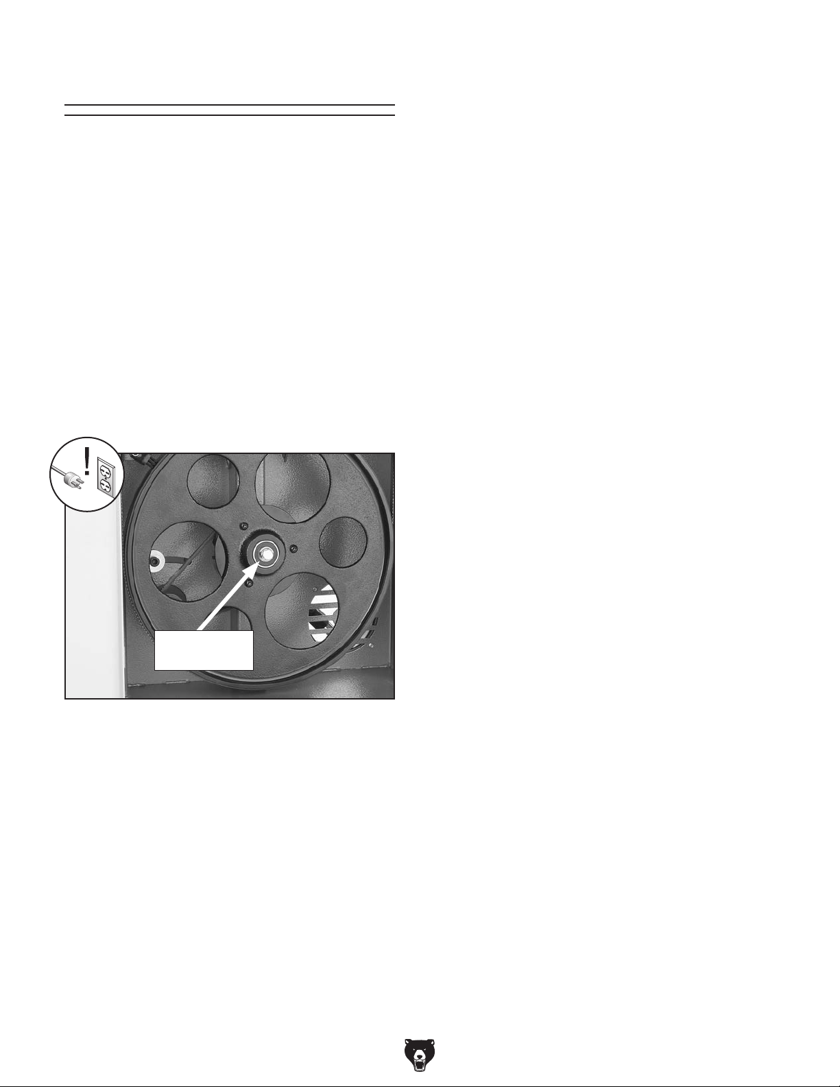
Replacing V-Belt
Tools Needed: QTY
Hex Wrench 6mm ...............................................1
Wrench 13mm ....................................................1
To replace the V-belt:
1. DISCONNECT BANDSAW FROM POWER!
2. Open both wheel covers, and remove the
blade.
3. Loosen the motor screws shown in Figure
59.
4. Unthread the wheel mount bolt shown in
Figure 61 and slide the lower wheel off of the
bearing shaft.
5. Move the body of the motor so that the motor
adjustment screw slides to the right-hand
side (facing bandsaw front) of the adjustment
slot and pull the V-belt off of the motor pulley.
6. Slip the old V-belt off of the wheel pulley and
install the new V-belt in its place.
7. Install the lower wheel back onto the bearing
shaft and replace/tighten the wheel mount
bolt.
8. Position the V-belt over the motor pulley.
Move the body of the motor so that the motor
adjustment screw slides to the left-hand side
(facing bandsaw front) of the adjustment
slot.
9. Hold the motor in position with one hand and
tighten the motor adjustment screw with the
other hand.
Wheel Mount
Bolt
Figure 61. Wheel mount bolt.
10. Check the V-belt tension and adjust if neces-
sary as described in the Tensioning V-Belt
instructions on Page 45.
11. When the V-belt tension is correct, tighten
the motor hinge bolt, replace the blade, then
close both wheel covers.
-46-
G0457 14" Industrial Bandsaw (Mfg. Since 5/11)
Page 65

Shimming Table Blade Lead
To ensure accuracy when cutting stacked
workpieces, the table should be 90˚ to the back of
the blade as shown in Figure 62. If the table is not
perpendicular to the back of the blade, the table
needs to be shimmed.
Shims can be made of any durable object that
can be sandwiched between the table and the
trunnions. We recommend using shim washers or
shim stock because of the wide range of available
thicknesses. These items can be purchased at
your local hardware store.
Bandsaw blades sometimes wander off the cut
line when sawing, as shown in Figure 63. This is
called blade lead. Blade lead is commonly caused
by too fast of a feed rate, a dull or abused blade,
or improper tension. If your blade is sharp/undamaged and you still have blade lead, perform the
following instructions.
Front Back
Figure 62. Squaring table to blade back.
To shim the table:
1. Make sure that the blade is tracking properly
and that it is correctly tensioned.
2. DISCONNECT BANDSAW FROM POWER!
3. Loosen the table mounting bolts that secure
the table to the trunnion.
4. Place shims between the table and the trunnion to position the table in the desired direction.
5. Follow the Aligning Table instructions on
Page 22 to complete this procedure.
Figure 63. Blade leading away from line of cut.
Correct blade lead
1. Use less pressure when feeding the workpiece
through the cut.
2. Check that the miter slot or fence is parallel
to the blade line, and correct if necessary.
3. Check for proper blade tension. If the blade
tension is correct and it is not convenient to
replace the blade, compensate for lead by
skewing the fence or adjusting the table.
Skewing your fence
1. Cut a piece of scrap wood approximately 3⁄4"
thick x 3" wide x 17" long. On a wide face of
the board, draw a straight line parallel to the
long edge.
2. Cut halfway through the board on the line by
pushing it into the blade. Turn the bandsaw
OFF and wait for the blade to stop.
G0457 14" Industrial Bandsaw (Mfg. Since 5/11)
-47-
Page 66

3. Clamp the board to the bandsaw table without moving it. Now slide the fence over to
the board so it barely touches one end of the
board.
Shifting Table
1. On a scrap piece of wood, mark a line that is
perpendicular to the front edge.
4. Loosen the four cap screws on top of the
fence.
5. Skew the fence so it is parallel to the edge of
the scrap piece. You may need to re-adjust
the fence locking mechanisms to gain maximum adjustment.
6. While maintaining the skew, tighten the cap
screws.
NOTICE
Lead adjustments will change when new
blades are mounted on the saw.
2. Cut halfway through the board on the line by
pushing it into the blade.
3. Turn the bandsaw OFF and wait for the blade
to stop.
4. Loosen the table mounting bolts, shift the
table to compensate for the blade lead, then
retighten the bolts.
5. Repeat Steps 1–4 until the blade cuts
straight.
NOTICE
If the table is shifted, the fence will need
to be re-aligned, and the blade guides and
blade support will need to be re-adjusted.
-48-
G0457 14" Industrial Bandsaw (Mfg. Since 5/11)
Page 67
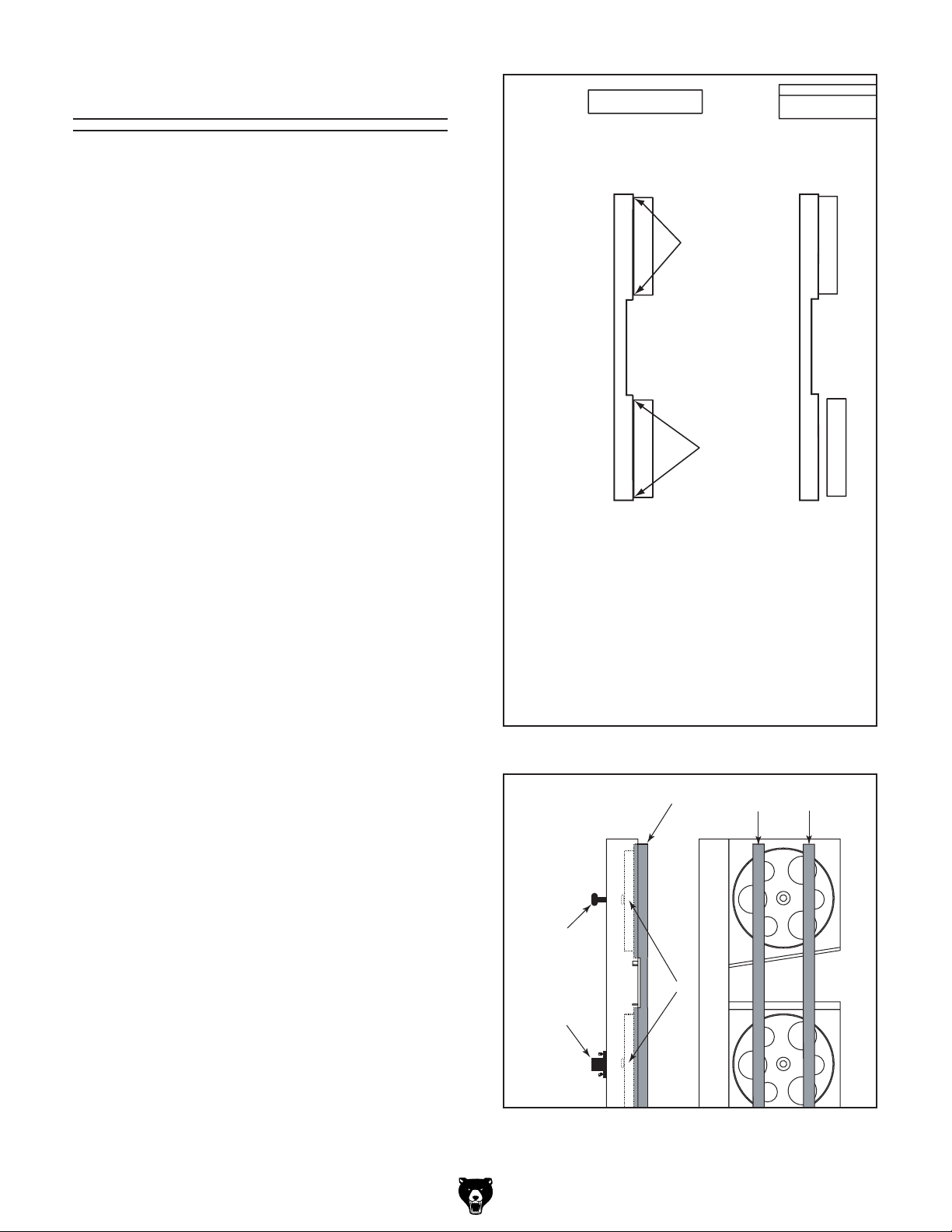
Wheel Alignment
Coplanar
Parallel, Not
Coplanar
Not Parallel
Not Coplanar
Adjust
Tracking Knob
Coplanarity Gauge
Contacts Top
And Bottom of
Both Wheels
Coplanarity Gauge
Coplanarity
Gauge
Gauge Positions
Tracking
Knob
Adjustment
Hub
Wheels
Components and Hardware Needed: Qty
1
/2" Long 2x4 .................................................. 1
45
Tools Needed:
Wrench 13mm ................................................... 1
Tape Measure .................................................... 1
Coplanarity Gauge (see Figure 64) .................. 1
Wheel alignment is one of the most critical factors
for optimal performance from your bandsaw.
Heat, vibration, wandering, blade wear, tire wear
and overall bandsaw wear are considerably
decreased when the wheels are properly aligned
or “coplanar.”
Coplanar wheels automatically track the blade
by balancing it on the crown of the wheel. This is
known as coplanar tracking.
To check if your wheels are coplanar:
1. Make the "Coplanarity Gauge" shown in
Note: For best results, straighten the 2x4
2. Remove the fence and table, then open both
3. Make sure the guide blocks and rear sup-
4. Place your coplanarity gauge up against both
5. The adjustment hub allows you to move the
Figure 64.
with a jointer before cutting.
wheel covers.
port bearings are away from the blade, then
tighten your blade to the tension that it will be
used during operation.
wheels in the positions shown in Figure 65.
lower wheel in the desired direction. Turning
all the bolts clockwise in equal amounts pushes the wheel forward. Turning all the bolts
counterclockwise brings the wheel backward,
closer to the adjustment hub. Used individually, each bolt can control the direction that
the wheel tilts.
Figure 64. Dimensions of coplanarity gauge.
Figure 65. Checking for coplanarity.
G0457 14" Industrial Bandsaw (Mfg. Since 5/11)
-49-
Page 68

6. Adjust the tracking knob to get both wheels
Coplanar
Parallel, Not
Coplanar
Not Parallel
Not Coplanar
Adjust
Tracking Knob
Coplanarity Gauge
Contacts Top
And Bottom of
Both Wheels
Coplanarity Gauge
parallel. If the wheels won’t go parallel to
each other, then move the lower wheel at the
adjustment hub so they line up.
Top Tilt
7. If the wheels will go parallel but not coplanar,
then move the lower wheel at the adjustment
hub (Figure 66) as necessary.
8. Figure 67 shows the positions of the wheels
when coplanar. When your wheels are coplanar, readjust the guide blocks and rear support bearings, and replace the wheel covers.
Note: The blade may track slightly OFF center
when the wheels are coplanar. This is natural
because the blade will be balanced ON the crown
of the tire, rather than just in the center of the tire.
This will be more noticeable with larger blades.
Side
Side
Tilt
Tilt
Bottom Tilt
Figure 66. Lower wheel adjustment control.
-50-
Figure 67. Coplanarity diagram.
G0457 14" Industrial Bandsaw (Mfg. Since 5/11)
Page 69

These pages are current at the time of printing. However, in the spirit of improvement, we may make changes to the electrical systems of future machines. Compare the manufacture date of your machine to the one
number and manufacture date of your
machine before calling. This information can be found on the main machine label.
machine
SECTION 8: WIRING
stated in this manual, and study this section carefully.
If there are differences between your machine and what is shown in this section, call Technical Support at
(570) 546-9663 for assistance BEFORE making any changes to the wiring on your machine. An updated
wiring diagram may be available. Note: Please gather the serial
Wiring Safety Instructions
SHOCK HAZARD. Working on wiring that is con-
nected to a power source is extremely dangerous.
Touching electrified parts will result in personal
injury including but not limited to severe burns,
electrocution, or death. Disconnect the power
from the machine before servicing electrical components!
MODIFICATIONS. Modifying the wiring beyond
what is shown in the diagram may lead to unpredictable results, including serious injury or fire.
This includes the installation of unapproved aftermarket parts.
WIRE CONNECTIONS. All connections must
be tight to prevent wires from loosening during
machine operation. Double-check all wires disconnected or connected during any wiring task to
ensure tight connections.
CIRCUIT REQUIREMENTS. You MUST follow
the requirements at the beginning of this manual
when connecting your machine to a power source.
WIRE/COMPONENT DAMAGE. Damaged wires
or components increase the risk of serious personal injury, fire, or machine damage. If you notice
that any wires or components are damaged while
performing a wiring task, replace those wires or
components.
MOTOR WIRING. The motor wiring shown in
these diagrams is current at the time of printing
but may not match your machine. If you find this
to be the case, use the wiring diagram inside the
motor junction box.
CAPACITORS/INVERTERS. Some capacitors
and power inverters store an electrical charge for
up to 10 minutes after being disconnected from
the power source. To reduce the risk of being
shocked, wait at least this long before working on
capacitors.
EXPERIENCING DIFFICULTIES. If you are experiencing difficulties understanding the information
included in this section, contact our Technical
Support at (570) 546-9663.
The photos and diagrams
included in this section are
best viewed in color. You
can view these pages in
color at www.grizzly.com.
G0457 14" Industrial Bandsaw (Mfg. Since 5/11)
-51-
Page 70
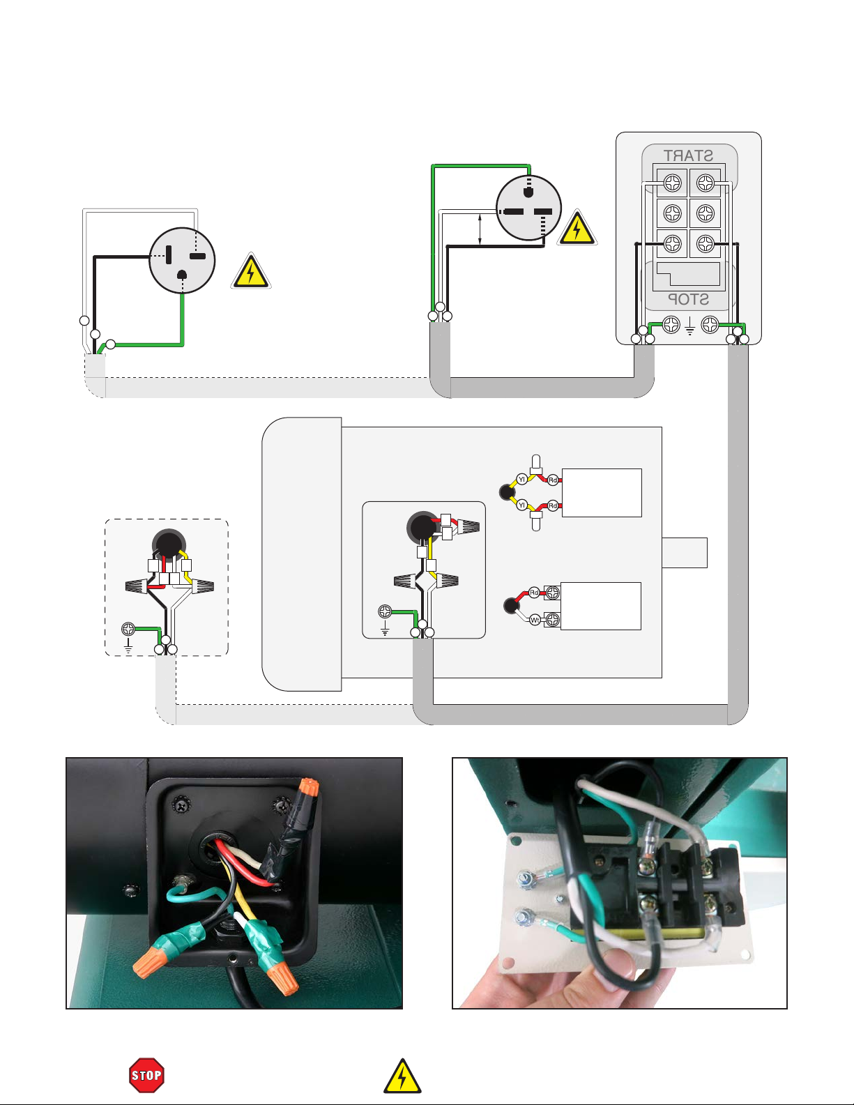
PUSH BUTTON SWITCH
START
STOP
Ground
Ground
(viewed from behind)
Neutral
Wt
Bl
Hot
Ground
Gn
Rewired to 110V
110V
1
3
Bl
Gn
110V
5-20 Plug
(As Recommended)
4
2
Wt
Ground
Hot
220
VAC
Hot
Wt
Gn
Bl
220V (Prewired)
3
2
1
4
Wt
Bl
Gn
220V
G
6-15 Plug
(As Recommended)
Capacitor
40MFD
250VAC
Capacitor
300MFD
250VAC
Run
Start
Wt
Bl
Gn
Bl
Gn
Wt
-52-
Rewired to 110V
Figure 68. Motor wiring. Figure 69. Push button switch wiring.
READ ELECTRICAL SAFETY
G0457 14" Industrial Bandsaw (Mfg. Since 5/11)
ON PAGE 51!
Page 71
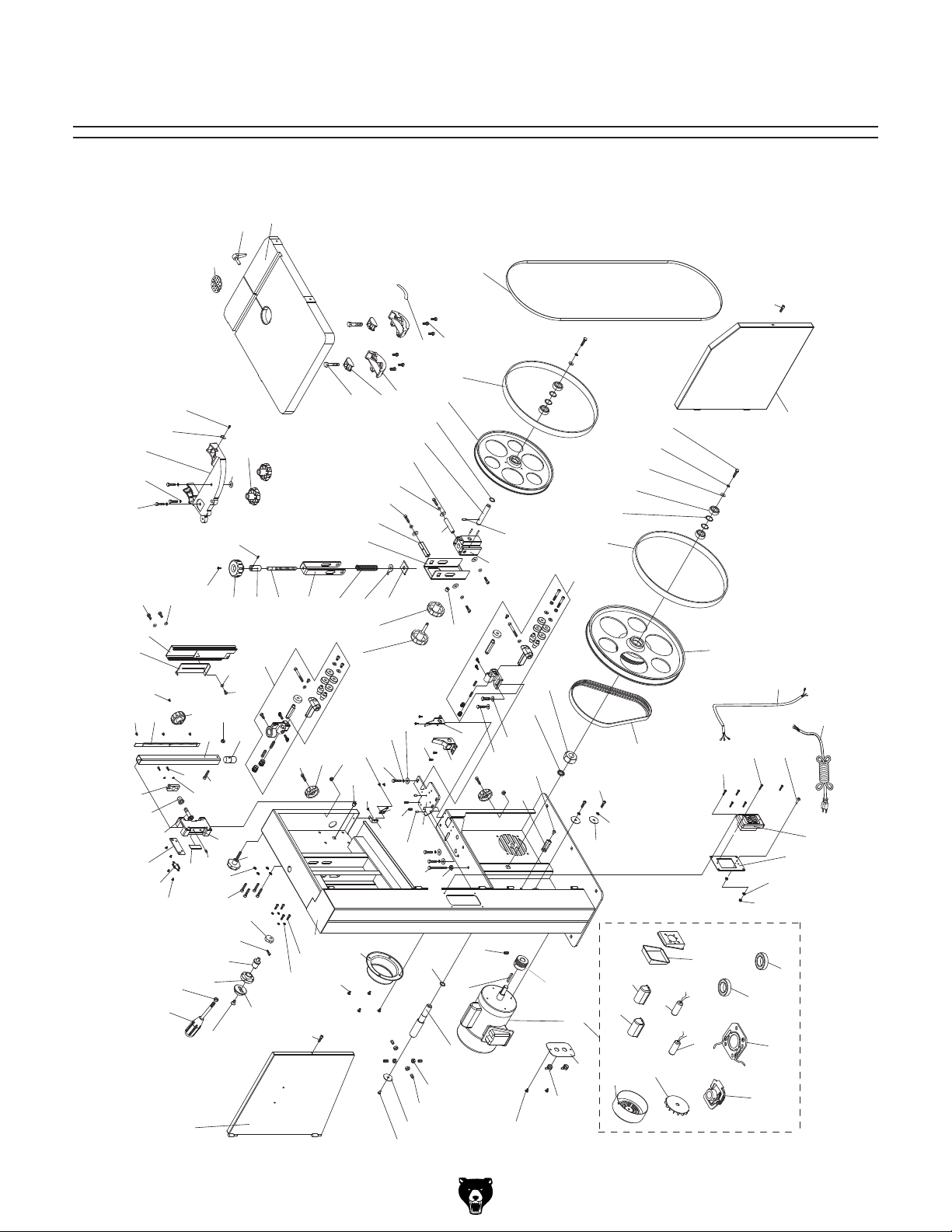
SECTION 9: PARTS
Main
128
127
120A
119
118
52
51
50
35
30
29
33
54
36
28
27
123
53
26
12
124
11
32
161
2
37
31
126
54
38
34
162
23
8
10
42
25
22
7
160
57
37
41
6
125
40
39
55
56
24
9
43
58
5
59
100
4
21
101
1
95
60
102
129
67
61
63
104
66
94
68
64
151
130
70
69
62
159
158
150
131
71
160
111
164
103
93
92
132
76
75
104
157
121
76
90
91
77
72
122
133
78
66
89
97
88
134
105
204
73
112
74
65
116
142
87
117
86
203
143
78
44
115
113
96V2
144
81
82
83
202
114
96V2-10
96V2-3
96V2-1
96V2-2
79
80
96V2-11
201
135
96V2-5
96V2-4
21
141
136
137
138
139
96V2-8
96V2-7
96V2-6
3
140V2
146V2
145
96V2-9
G0457 14" Industrial Bandsaw (Mfg. Since 5/11)
-53-
Page 72

Main Parts List
REF PART # DESCRIPTION REF PART # DESCRIPTION
1 P0457001 BODY 68 P0457068 SQUARE SHAFT 12 X 12MM
2 P0457002 UPPER WHEEL DOOR 69 PCAP14M CAP SCREW M8-1.25 X 20
3 P0457003 LOWER WHEEL DOOR 70 PLW04M LOCK WASHER 8MM
4 PCAP04M CAP SCREW M6-1 X 10 71 PW01M FLAT WASHER 8MM
5 PLW03M LOCK WASHER 6MM 72 P0457072 SLEEVE
6 PCAP33M CAP SCREW M5-.8 X 12 73 P0457073 UPPER WHEEL SHAFT BRACKET
7 P0457007 BIAS SHAFT 74 PRP91M ROLL PIN 5 X 35
8 P0457008 BIAS SHAFT CLAMP SEAT 75 P0457075 UPPER WHEEL SHAFT
9 P0457009 TENSION ADJUSTMENT HUB 76 P0457076 WAVY WASHER 15 X 22MM
10 PCAP14M CAP SCREW M8-1.25 X 20 77 P0457077 UPPER WHEEL
11 PN03M HEX NUT M8-1.25 78 P0457078 WHEEL TIRE
12 P0457012 TENSION HANDLE 79 PB03M HEX BOLT M8-1.25 X 16
21 PCAP04M CAP SCREW M6-1 X 10 80 PLW04M LOCK WASHER 8MM
22 PLW04M LOCK WASHER 8MM 81 PW01M FLAT WASHER 8MM
23 PCAP14M CAP SCREW M8-1.25 X 20 82 P6202ZZ BALL BEARING 6202ZZ
24 P0457024 LOCK KNOB M8-1.25 X 20 83 PR21M INT RETAINING RING 35MM
25 P0457025 UPPER GUIDE POST SUPPORT 86 PN15M HEX NUT M18-1.5
26 PFH27M FLAT HD SCR M4-.7 X 6 87 PLW12M LOCK WASHER 18MM
27 P0457027 SPRING TENSIONER 88 P0457088 LOWER WHEEL SHAFT
28 P0457028 ADJUSTMENT GEAR SHAFT 89 P0457089 LEFT BLADE COVER
29 P0457029 BUSHING 90 PN03M HEX NUT M8-1.25
30 P0457030 GEAR SHAFT BRACKET 91 PSS09M SET SCREW M8-1.25 X 20
31 PLW03M LOCK WASHER 6MM 92 P0457092 SHAFT END CAP
32 PCAP04M CAP SCREW M6-1 X 10 93 PFS01M FLANGE SCREW M5-.8 X 8
33 P0457033 COVER PLATE 94 P0457094 DUST PORT
34 PCAP48M CAP SCREW M6-1 X 35 95 PFS11M FLANGE SCREW M6-1 X 10
35 PFH27M FLAT HD SCR M4-.7 X 6 96V2 P0457096V2 MOTOR 2HP 1PH 220/110V V2.05.11
36 P0457036 RACK 96V2-1 P0457096V2-1 MOTOR FAN COVER
37 P0457037 HAND KNOB M10-1.5 96V2-2 P0457096V2-2 MOTOR FAN
38 P0457038 GUIDE POST 96V2-3 P0457096V2-3 S CAPACITOR COVER
39 P0457039 CHANGE SHAFT 96V2-4 P0457096V2-4 S CAPACITOR 300M 250V
40 PS14M PHLP HD SCR M6-1 X 12 96V2-5 P0457096V2-5 MOTOR JUNCTION BOX
41 P0457041 WASHER 6MM PLASTIC 96V2-6 P0457096V2-6 CENTRIFUGAL SWITCH
42 PLN03M LOCK NUT M6-1 96V2-7 P0457096V2-7 CONTACT PLATE
43 P0457043 UPPER BLADE GUIDE ASSEMBLY 96V2-8 P0457096V2-8 FRONT MOTOR BEARING
44 P0457044 LOWER BLADE GUIDE ASSEMBLY 96V2-9 P0457096V2-9 REAR MOTOR BEARING
50 P0457050 SLIDING BLADE GUARD 96V2-10 P0457096V2-10 R CAPACITOR COVER
51 P0457051 BLADE GUARD 96V2-11 PC040F R CAPACITOR 40M 250V 1-3/8 X 2-3/8
52 PB05M HEX BOLT M6-1 X 8 97 PK34M KEY 5 X 5 X 20
53 PW03M FLAT WASHER 6MM 100 PCAP02M CAP SCREW M6-1 X 20
54 PFS06M FLANGE SCREW M6-1 X 8 101 P0457101 WHEEL COVER LATCH KNOB 6MM
55 P0457055 CAM 102 PLN03M LOCK NUT M6-1
56 P0457056 LOCK COLLAR 103 P0457103 ALIGNMENT PIN
57 PSS07M SET SCREW M5-.8 X 5 104 PFS03M FLANGE SCREW M5-.8 X 6
58 P0457058 TENSION ADJUSTMENT SCREW 105 P0457105 RIGHT BLADE COVER
59 P0457059 ADJUSTMENT SCREW BRACKET 111 P0457111 POINTER
60 P0457060 COMPRESSION SPRING 112 PB02M HEX BOLT M6-1 X 12
61 P0457061 TENSION INDICATOR 113 PW01M FLAT WASHER 8MM
62 P0457062 THREADED PLATE 114 PLW04M LOCK WASHER 8MM
63 P0457063 LOCK KNOB M8-1.25 X 45 115 PCAP14M CAP SCREW M8-1.25 X 20
64 P0457064 KNOB M8-1.25 116 P0457116 WHEEL BRUSH
65 PW03M FLAT WASHER 6MM 117 PFS01M FLANGE SCREW M5-.8 X 8
66 P0457066 PULL NUT M8-1.25 118 PB20M HEX BOLT M8-1.25 X 35
67 P0457067 BRACKET
-54-
G0457 14" Industrial Bandsaw (Mfg. Since 5/11)
Page 73

Main Parts List (Continued)
REF PART # DESCRIPTION REF PART # DESCRIPTION
119 PLW04M LOCK WASHER 8MM 140V2 P0457140V2 POWER CORD 14G 3C 6-15 V2.05.11
120A P0457120A TRUNNION BRACKET, CAST IRON 141 P0457141 MOTOR CORD 14G 3C
121 PB82M HEX BOLT M8-1.25 X 80 142 PFS01M FLANGE SCREW M5-.8 X 8
122 PN03M HEX NUT M8-1.25 143 P0457143 STRAIN RELIEF
123 P0457123 POINTER 144 P0457144 SWITCH BOX REAR PLATE
124 PS19M PHLP HD SCR M5-.8 X 6 145 P0457145 SWITCH BOX FRONT PLATE
125 P0457125 LOCK KNOB M10-1.5 146V2 P0555014V2 ON/OFF SWITCH 110/220V V2.05.11
126 P0513X127 TABLE INSERT 150 P0457150 POINTER BRACKET
127 P0457127 TABLE PIN 151 PFS12M FLANGE SCREW M5-.8 X 12
128 P0457128 TABLE 157 P0457157 LEVER PLATE
129 PB73M HEX BOLT M10-1.5 X 50 158 PB09M HEX BOLT M8-1.25 X 20
130 P0457130 TRUNNION CLAMP SHOE 1PC 159 PLW04M LOCK WASHER 8MM
131 P0457131 TRUNNION 160 PW01M FLAT WASHER 8MM
132 P0457132 SCALE 161 P0457161 SHIM PLASTIC
133 PFB01M FLANGE BOLT M6-1 X 12 162 PSS02M SET SCREW M6-1 X 6
134 P0457134 BLADE 106 X 3/8 X 0.35" 6TPI 164 PSS16M SET SCREW M8-1.25 X 10
135 PFS01M FLANGE SCREW M5-.8 X 8 201 P0457201 WHEEL LOWER ASSEMBLY
136 PS38M PHLP HD SCR M4-.7 X 10 202 P0457202 RIBBED BELT 200J5
137 PS08M PHLP HD SCR M5-.8 X 12 203 P0457203 MOTOR PULLEY
138 PTLW02M EXT TOOTH WASHER 5MM 204 PSS01M SET SCREW M6-1 X 10
139 PN06M HEX NUT M5-.8
G0457 14" Industrial Bandsaw (Mfg. Since 5/11)
-55-
Page 74

Components
149-22
149-10
148
149-24
149-6
149
149-8
149-14
149-7
149-29
149-19
149-20
149-30
149-18
149-12
149-27
149-2
149-3
149-11
149-5
149-28
149-16
149-4
149-13
149-15
149-26
149-9
149-23
149-25
149-21
149-1
149-17
149-20
REF PART # DESCRIPTION REF PART # DESCRIPTION
148 P0457148 MITER GAUGE ASSEMBLY 149-15 PN03M HEX NUT M8-1.25
149 H7587 RESAW FENCE ASSEMBLY 149-16 PFS04M FLANGE SCREW M4-.7 X 6
149-1 PH7587001 FRONT FENCE RAIL 540MM 149-17 P0457149-17 FRONT RAIL END CAP
149-2 PH7587002 FENCE BASE 149-18 PH7528002 FENCE MOUNTING PLATE
149-3 PH7587003 FENCE SUPPORT MOUNTING ROD 149-19 P0457149-19 REAR RAIL END CAP
149-4 PH7587004 LOCK ROD 149-20 PHTEK3M TAP SCREW M3.5 X 8
149-5 PH7587005 SPRING PIECE 149-21 P0457149-21 SCALE
149-6 PH7584004 LOCK HANDLE ASSEMBLY M8-1.25 X 44 149-22 PN01M HEX NUT M6-1
149-7 PH7587007 FENCE SUPPORT 505MM 149-23 PLW03M LOCK WASHER 6MM
149-8 PW01M FLAT WASHER 8MM 149-24 PCAP01M CAP SCREW M6-1 X 16
149-9 PH7587009 LOCK HANDLE 149-25 PB08M HEX BOLT M6-1 X 20
149-10 PH7587010 FENCE REAR STANDOFF 149-26 PFS17M FLANGE SCREW M4-.7 X 8
149-11 PH7587011 SCALE WINDOW 149-27 PW03M FLAT WASHER 6MM
149-12 PCAP06M CAP SCREW M6-1 X 25 149-28 PH7528001 FENCE 505MM ALUMINUM
149-13 PH7587013 LOCK CAM 149-29 P0555306 FENCE SUPPORT MOUNTING PLATE
149-14 PH7587014 REAR FENCE RAIL 149-30 P0457149-30 FENCE END CAP
-56-
G0457 14" Industrial Bandsaw (Mfg. Since 5/11)
Page 75

302
Stand
301
303
305
304
307
308
309
REF PART # DESCRIPTION REF PART # DESCRIPTION
301 PCB01M CARRIAGE BOLT M8-1.25 X 20 306 P0457306 LATCH ASSEMBLY
302 P0457302 STAND 307 PW02 FLAT WASHER 3/8
303 P0457303 FLANGE NUT M8-1.25 308 PN08 HEX NUT 3/8-16
304 P0457304 FOAM TAPE 309 P0457309 FOOT 3/8-16 X 1-3/4
305 P0457305 DOOR
306
G0457 14" Industrial Bandsaw (Mfg. Since 5/11)
-57-
Page 76
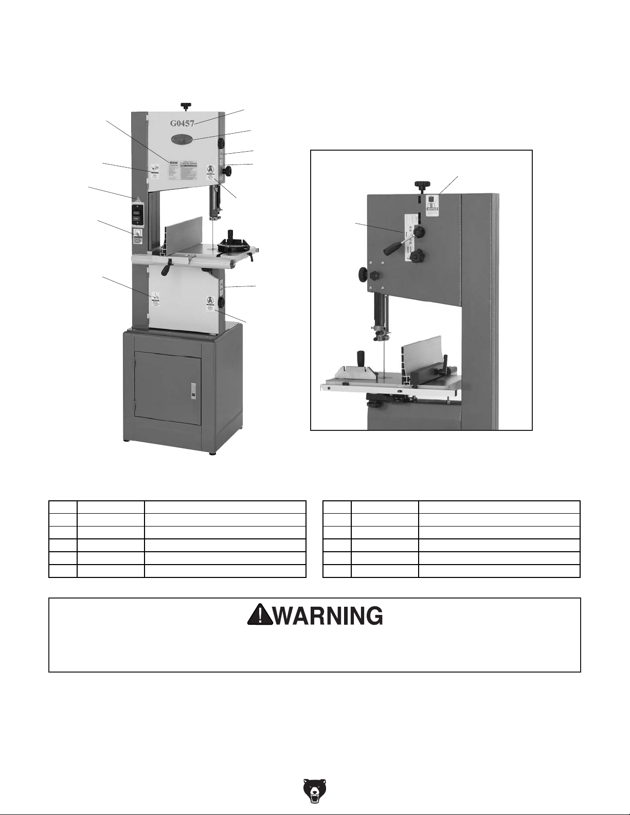
408
401
404
405
Labels
410
409
407
411
406
402
403
407
405
412
Rear of Machine
REF PART # DESCRIPTION REF PART # DESCRIPTION
401 P0457401 MACHINE ID LABEL 407 PLABEL-19 HANDS NEAR BLADE LABEL
402 PLABEL-12 READ MANUAL LABEL 408 PLABEL-14 ELECTRICITY LABEL
403 PLABEL-18 UNPLUG BANDSAW LABEL 409 G9987 GRIZZLY NAMEPLATE
404 PLABEL-11 SAFETY GLASSES LABEL 410 P0457410 MODEL NUMBER LABEL
405 PLABEL-23 DO NOT OPEN LABEL 411 P0457411 BLADE GUARD ADJ LABEL
406 P0457406 BLADE TENSION NOTICE LABEL 412 P0457412 BLADE TENSION SCALE/LABEL
Safety labels help reduce the risk of serious injury caused by machine hazards. If any label comes
off or becomes unreadable, the owner of this machine MUST replace it in the original location
before resuming operations. For replacements, contact (800) 523-4777 or www.grizzly.com.
-58-
G0457 14" Industrial Bandsaw (Mfg. Since 5/11)
Page 77

WARRANTY CARD
Name _____________________________________________________________________________
Street _____________________________________________________________________________
City _______________________ State _________________________ Zip _____________________
Phone # ____________________ Email _________________________________________________
Model # ____________________ Order # _______________________ Serial # __________________
The following information is given on a voluntary basis. It will be used for marketing purposes to help us develop
better products and services. Of course, all information is strictly confidential.
1. How did you learn about us?
____ Advertisement ____ Friend ____ Catalog
____ Card Deck ____ Website ____ Other:
2. Which of the following magazines do you subscribe to?
____ Cabinetmaker & FDM
____ Family Handyman
____ Hand Loader
____ Handy
____ Home Shop Machinist
____ Journal of Light Cont.
____ Live Steam
____ Model Airplane News
____ Old House Journal
____ Popular Mechanics
3. What is your annual household income?
____ $20,000-$29,000 ____ $30,000-$39,000 ____ $40,000-$49,000
____ $50,000-$59,000 ____ $60,000-$69,000 ____ $70,000+
CUT ALONG DOTTED LINE
4. What is your age group?
____ 20-29 ____30-39 ____ 40-49
____ 50-59 ____60-69 ____ 70+
5. How long have you been a woodworker/metalworker?
____ 0-2 Years ____ 2-8 Years ____ 8-20 Years ____20+ Years
6. How many of your machines or tools are Grizzly?
____ 0-2 ____ 3-5 ____ 6-9 ____10+
____ Popular Science
____ Popular Woodworking
____ Precision Shooter
____ Projects in Metal
____ RC Modeler
____ Rie
____ Shop Notes
____ Shotgun News
____ Today’s Homeowner
____ Wood
____ Wooden Boat
____ Woodshop News
____ Woodsmith
____ Woodwork
____ Woodworker West
____ Woodworker’s Journal
____ Other:
7. Do you think your machine represents a good value? _____Yes _____No
8. Would you recommend Grizzly Industrial to a friend? _____Yes _____No
9. Would you allow us to use your name as a reference for Grizzly customers in your area?
Note: We never use names more than 3 times. _____Yes _____No
10. Comments: _____________________________________________________________________
_________________________________________________________________________________
_________________________________________________________________________________
_________________________________________________________________________________
Page 78

FOLD ALONG DOTTED LINE
FOLD ALONG DOTTED LINE
Place
Stamp
Here
GRIZZLY INDUSTRIAL, INC.
P.O. BOX 2069
BELLINGHAM, WA 98227-2069
Send a Grizzly Catalog to a friend:
Name_______________________________
Street_______________________________
City______________State______Zip______
TAPE ALONG EDGES--PLEASE DO NOT STAPLE
Page 79

WARRANTY & RETURNS
Grizzly Industrial, Inc. warrants every product it sells for a period of 1 year to the original purchaser from
the date of purchase. This warranty does not apply to defects due directly or indirectly to misuse, abuse,
negligence, accidents, repairs or alterations or lack of maintenance. This is Grizzly’s sole written warranty
and any and all warranties that may be implied by law, including any merchantability or fitness, for any particular purpose, are hereby limited to the duration of this written warranty. We do not warrant or represent
that the merchandise complies with the provisions of any law or acts unless the manufacturer so warrants.
In no event shall Grizzly’s liability under this warranty exceed the purchase price paid for the product and
any legal actions brought against Grizzly shall be tried in the State of Washington, County of Whatcom.
We shall in no event be liable for death, injuries to persons or property or for incidental, contingent, special,
or consequential damages arising from the use of our products.
To take advantage of this warranty, contact us by mail or phone and give us all the details. We will then issue
you a “Return Number,’’ which must be clearly posted on the outside as well as the inside of the carton. We
will not accept any item back without this number. Proof of purchase must accompany the merchandise.
The manufacturers reserve the right to change specifications at any time because they constantly strive to
achieve better quality equipment. We make every effort to ensure that our products meet high quality and
durability standards and we hope you never need to use this warranty.
Please feel free to write or call us if you have any questions about the machine or the manual.
Thank you again for your business and continued support. We hope to serve you again soon.
Page 80

 Loading...