

Page 1

MODEL G0775
20" HEAVY-DUTY
DISC SANDER
OWNER'S MANUAL
(For models manufactured since 11/14)
COPYRIGHT © JANUARY, 2015 BY GRIZZLY INDUSTRIAL, INC.,
WARNING: NO PORTION OF THIS MANUAL MAY BE REPRODUCED IN ANY SHAPE
OR FORM WITHOUT THE WRITTEN APPROVAL OF GRIZZLY INDUSTRIAL, INC.
#BLMN17030 PRINTED IN TA IWA N
V1.01.15
Page 2

This manual provides critical safety instructions on the proper setup,
operation, maintenance, and service of this machine/tool. Save this
document, refer to it often, and use it to instruct other operators.
Failure to read, understand and follow the instructions in this manual
may result in fire or serious personal injury—including amputation,
electrocution, or death.
The owner of this machine/tool is solely responsible for its safe use.
This responsibility includes but is not limited to proper installation in
a safe environment, personnel training and usage authorization,
proper inspection and maintenance, manual availability and comprehension, application of safety devices, cutting/sanding/grinding tool
integrity, and the usage of personal protective equipment.
The manufacturer will not be held liable for injury or property damage
from negligence, improper training, machine modifications or misuse.
Some dust created by power sanding, sawing, grinding, drilling, and
other construction activities contains chemicals known to the State
of California to cause cancer, birth defects or other reproductive
harm. Some examples of these chemicals are:
• Lead from lead-based paints.
• Crystalline silica from bricks, cement and other masonry products.
• Arsenic and chromium from chemically-treated lumber.
Your risk from these exposures varies, depending on how often you
do this type of work. To reduce your exposure to these chemicals:
Work in a well ventilated area, and work with approved safety equipment, such as those dust masks that are specially designed to filter
out microscopic particles.
Page 3

Table of Contents
INTRODUCTION ............................................... 2
Machine Description ...................................... 2
Contact Info.................................................... 2
Manual Accuracy ........................................... 2
Identification ................................................... 3
Machine Data Sheet ...................................... 4
SECTION 1: SAFETY ....................................... 6
Safety Instructions for Machinery .................. 6
Additional Safety for Disc Sanders ................ 8
SECTION 2: POWER SUPPLY ........................ 9
SECTION 3: SETUP ....................................... 11
Unpacking .................................................... 11
Needed for Setup ......................................... 11
Inventory ...................................................... 12
Cleanup ........................................................ 13
Site Considerations ...................................... 14
Anchoring to Floor ....................................... 15
Assembly ..................................................... 15
Dust Collection ............................................. 16
Test Run ...................................................... 16
SECTION 4: OPERATIONS ........................... 17
Operation Overview ..................................... 17
Attaching Sandpaper ................................... 18
Disc Sanding ................................................ 18
SECTION 6: MAINTENANCE ......................... 23
Schedule ...................................................... 23
Cleaning & Protecting .................................. 23
SECTION 7: SERVICE ................................... 24
Troubleshooting ........................................... 24
Table Gap & Parallelism .............................. 26
Calibrating Miter Gauge ............................... 26
Table Tilt Calibration .................................... 27
SECTION 8: WIRING ...................................... 28
Wiring Safety Instructions ............................ 28
Electrical Components ................................. 29
Wiring Diagram ............................................ 30
SECTION 9: PARTS ....................................... 31
Main Breakdown .......................................... 31
Labels and Cosmetics ................................. 33
WARRANTY & RETURNS ............................. 37
SECTION 5: ACCESSORIES ......................... 20
Page 4
INTRODUCTION
We are proud to provide a high-quality owner’s
manual with your new machine!
We
instructions, specifications, drawings, and photographs
contained inside. Sometimes we make mistakes,
but
also
means that
you receive
will be slightly different than what is shown in
the manual
If you find this to be the case, and the difference
between the manual and machine leaves you
confused about a procedure
for an updated version. W
manuals
and
www.grizzly.com
Alternatively, you can call our Technical Support
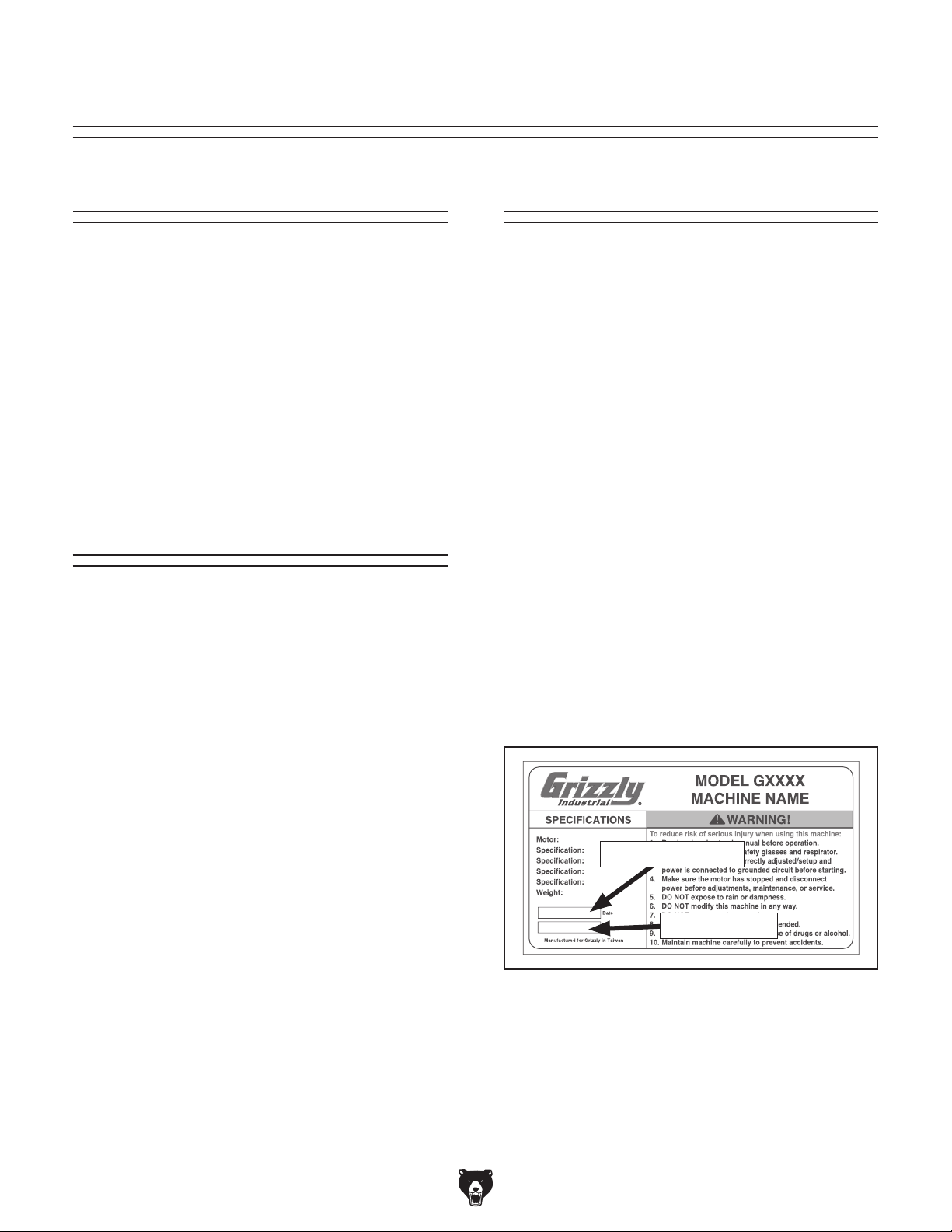
for help. Before calling, please write down the
Manufacture Date
stamped
into the machine ID label (see below). This information helps us determine if updated documentation is available for your machine.
We stand behind our machines. If you have
any questions or need help, use the information
below to contact us. Before contacting, please get
the serial number and manufacture date of your
machine. This will help us help you faster.
We want your feedback on this manual. What did
you like about it? Where could it be improved?
Please take a few minutes to give us feedback.
Email: manuals@grizzly.com
Machine Description
The Model G0775 features a 2 HP, 220V, 1720
RPM motor equipped with a built-in motor brake
for quickly stopping the 20" diameter sanding
disc, and a pedestal-mounted magnetic switch.
It includes a miter gauge and a large, tilting, cast
iron sanding table with X and Y miter slots, which
make it possible to sand many types of materials at virtually any angle—including compound
angles—with precision and control. The steel
powder-coated base has a 4" OD dust port and a
large cabinet for storing extra sanding discs.
Contact Info
Grizzly Technical Support
1203 Lycoming Mall Circle
Muncy, PA 17756
Phone: (570) 546-9663
Email: techsupport@grizzly.com
Grizzly Documentation Manager
P.O. Box 2069
Bellingham, WA 98227-2069
Manual Accuracy
made every effort to be exact with the
our policy of continuous improvement
sometimes the machine
.
, check our website
e post current
manual updates for free on our website at
.
and Serial Number
Manufacture Date
Serial Number
-2-
Model G0775 (Mfd. Since 11/14)
Page 5
Identification
To reduce your risk of
serious injury, read this
entire manual BEFORE
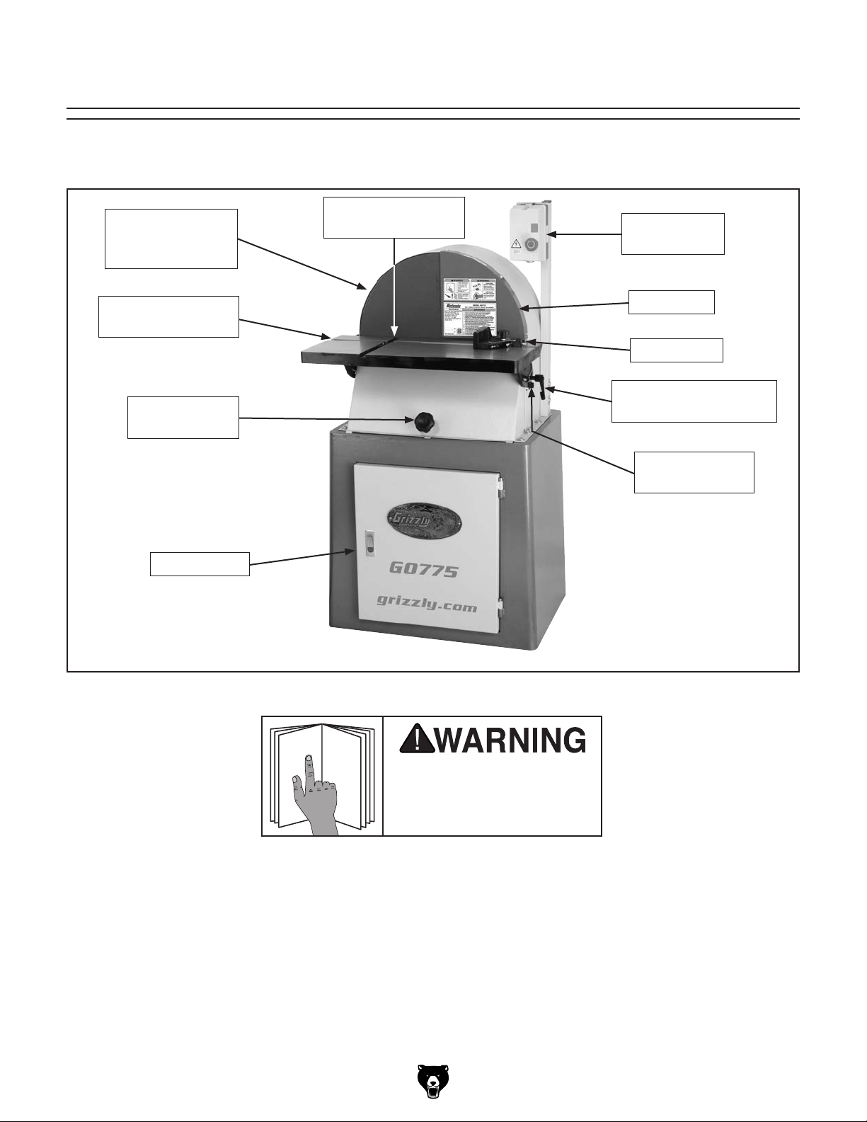
Become familiar with the names and locations of the controls and features shown below to better understand
the instructions in this manual.
Sanding Disc
(Attached to Cast
Iron Disc)
Work Table X-Axis
Miter Slot
45° Stop Knob
for Table Tilt
Cabinet Door
Work Table Y-Axis
Miter Slot
Magnetic ON/
OFF Switch
Disc Guard
Miter Gauge
Table Tilt Lock Handle
(1 of 2)
90° Stop Screw
for Table Tilt
Model G0775 (Mfd. Since 11/14)
Figure 1. Model G0775 identification.
using machine.
-3-
Page 6

Machine Data Sheet
MACHINE DATA
SHEET
Customer Service #: (570) 546-9663 · To Order Call: (800) 523-4777 · Fax #: (800) 438-5901
MODEL G0775 20" HEAVY-DUTY DISC SANDER
Product Dimensions:
Weight.............................................................................................................................................................. 392 lbs.
Width (side-to-side) x Depth (front-to-back) x Height............................................................... 25 x 28-1/2 x 51-1/4 in.
Footprint (Length x Width)..................................................................................................................... 26-1/2 x 19 in.
Shipping Dimensions:
Type........................................................................................................................... Cardboard Box with Wood Base
Content........................................................................................................................................................... Machine
Weight.............................................................................................................................................................. 434 lbs.
Length x Width x Height....................................................................................................................... 29 x 28 x 56 in.
Must Ship Upright................................................................................................................................................... Yes
Electrical:
Power Requirement........................................................................................................... 220V, Single-Phase, 60 Hz
Full-Load Current Rating....................................................................................................................................... 9.5A
Minimum Circuit Size.............................................................................................................................................. 15A
Connection Type....................................................................................................................................... Cord & Plug
Power Cord Included.............................................................................................................................................. Yes
Power Cord Length................................................................................................................................................. 6 ft.
Power Cord Gauge......................................................................................................................................... 14 AWG
Plug Included.......................................................................................................................................................... Yes
Included Plug Type.................................................................................................................................... NEMA 6-15
Switch Type........................................................................................................................................ Magnetic Switch
Motors:
Main
Type................................................................................................................... TEFC Capacitor-Start w/Brake
Horsepower................................................................................................................................................ 2 HP
Phase............................................................................................................................................ Single-Phase
Amps........................................................................................................................................................... 9.5A
Speed................................................................................................................................................ 1720 RPM
Power Transfer ............................................................................................................................... Direct Drive
Bearings........................................................................................................ Sealed & Permanently Lubricated
Main Specifications:
Disc Sander Info
Disc Diameter............................................................................................................................................ 20 in.
Disc Speed........................................................................................................................................ 1720 RPM
Disc Sandpaper Backing Type.................................................................................................................... PSA
Table Length...................................................................................................................................... 25-1/16 in.
Table Width................................................................................................................................................ 12 in.
Table Thickness.................................................................................................................................... 1-3/8 in.
Table Tilt....................................................................................................................................... Right 45 deg.
Table-to-Floor Height................................................................................................................................. 36 in.
-4-
Model G0775 (Mfd. Since 11/14)
Page 7

Construction Materials
Base........................................................................................................................................................... Steel
Stand.......................................................................................................................................................... Steel
Table.................................................................................................................................................... Cast Iron
Frame......................................................................................................................................................... Steel
Disc...................................................................................................................................................... Cast Iron
Miter Gauge........................................................................................................................................ Aluminum
Paint Type/Finish....................................................................................................................... Powder-Coated
Other Related Info
Miter Gauge Slot Width............................................................................................................................. 3/4 in.
Miter Gauge Slot Height......................................................................................................................... 5/16 in.
Number of Dust Ports....................................................................................................................................... 1
Dust Port Size.............................................................................................................................................. 4 in.
Compatible Mobile Base........................................................................................................................ D2057A
Other Specifications:
Country of Origin .............................................................................................................................................. Taiwan
Warranty ........................................................................................................................................................... 1 Year
Approximate Assembly & Setup Time ........................................................................................................ 15 Minutes
Serial Number Location .................................................................................................................................. ID Label
Sound Rating ..................................................................................................................................................... 75 dB
ISO 9001 Factory .................................................................................................................................................. Yes
CSA, ETL, or UL Certified/Listed ............................................................................................................................ No
Features:
Pedestal-mounted magnetic switch for convenience
Accepts 20" PSA discs
Large storage cabinet
Cast iron table with X and Y miter slots
Miter gauge
Built-in motor brake for quick stops
4" dust port
45 degree table tilt
Model G0775 (Mfd. Since 11/14)
-5-
Page 8
SECTION 1: SAFETY
For Your Own Safety, Read Instruction
Manual Before Operating This Machine
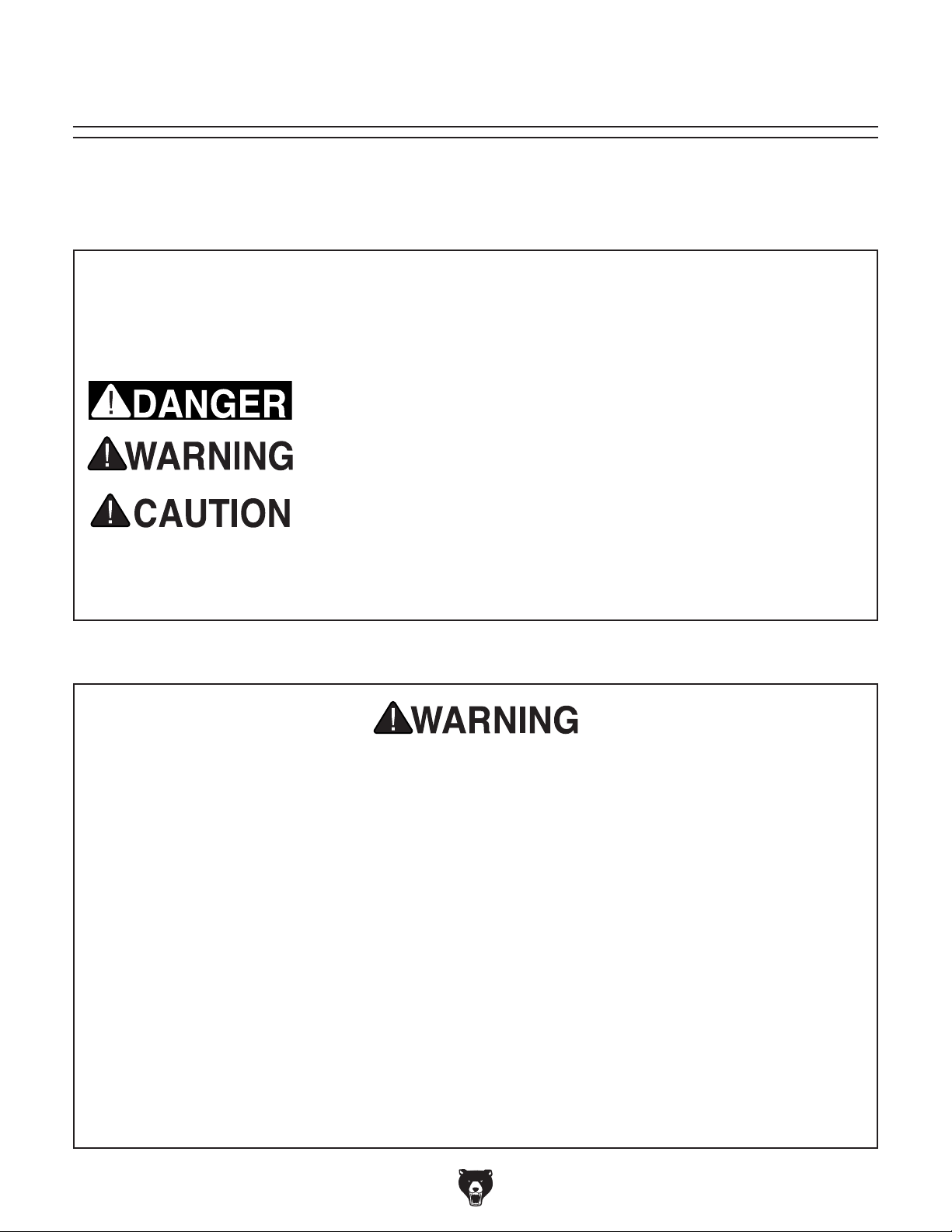
The purpose of safety symbols is to attract your attention to possible hazardous conditions.
This manual uses a series of symbols and signal words intended to convey the level of importance of the safety messages. The progression of symbols is described below. Remember that
safety messages by themselves do not eliminate danger and are not a substitute for proper
accident prevention measures. Always use common sense and good judgment.
Indicates an imminently hazardous situation which, if not avoided,
WILL result in death or serious injury.
Indicates a potentially hazardous situation which, if not avoided,
COULD result in death or serious injury.
Indicates a potentially hazardous situation which, if not avoided,
MAY result in minor or moderate injury. It may also be used to alert
against unsafe practices.
This symbol is used to alert the user to useful information about
NOTICE
proper operation of the machine.
Safety Instructions for Machinery
OWNER’S MANUAL. Read and understand this
owner’s manual BEFORE using machine.
TRAINED OPERATORS ONLY. Untrained operators have a higher risk of being hurt or killed.
Only allow trained/supervised people to use this
machine. When machine is not being used, disconnect power, remove switch keys, or lock-out
machine to prevent unauthorized use—especially
around children. Make workshop kid proof!
DANGEROUS ENVIRONMENTS. Do not use
machinery in areas that are wet, cluttered, or have
poor lighting. Operating machinery in these areas
greatly increases the risk of accidents and injury.
MENTAL ALERTNESS REQUIRED. Full mental
alertness is required for safe operation of machinery. Never operate under the influence of drugs or
alcohol, when tired, or when distracted.
ELECTRICAL EQUIPMENT INJURY RISKS. You
can be shocked, burned, or killed by touching live
electrical components or improperly grounded
machinery. To reduce this risk, only allow qualified
service personnel to do electrical installation or
repair work, and always disconnect power before
accessing or exposing electrical equipment.
DISCONNECT POWER FIRST.
nect machine from power supply BEFORE making
adjustments, changing tooling, or servicing machine.
This prevents an injury risk from unintended startup
or contact with live electrical components.
EYE PROTECTION. Always wear ANSI-approved
safety glasses or a face shield when operating or
observing machinery to reduce the risk of eye
injury or blindness from flying particles. Everyday
eyeglasses are NOT approved safety glasses.
Always discon-
-6-
Model G0775 (Mfd. Since 11/14)
Page 9

WEARING PROPER APPAREL. Do not wear
clothing, apparel or jewelry that can become
entangled in moving parts. Always tie back or
cover long hair. Wear non-slip footwear to avoid
accidental slips, which could cause loss of workpiece control.
HAZARDOUS DUST. Dust created while using
machinery may cause cancer, birth defects, or
long-term respiratory damage. Be aware of dust
hazards associated with each workpiece material,
and always wear a NIOSH-approved respirator to
reduce your risk.
HEARING PROTECTION. Always wear hearing protection when operating or observing loud
machinery. Extended exposure to this noise
without hearing protection can cause permanent
hearing loss.
REMOVE ADJUSTING TOOLS. Tools left on
machinery can become dangerous projectiles
upon startup. Never leave chuck keys, wrenches,
or any other tools on machine. Always verify
removal before starting!
USE CORRECT TOOL FOR THE JOB. Only use
this tool for its intended purpose—do not force
it or an attachment to do a job for which it was
not designed. Never make unapproved modifications—modifying tool or using it differently than
intended may result in malfunction or mechanical
failure that can lead to personal injury or death!
AWKWARD POSITIONS. Keep proper footing
and balance at all times when operating machine.
Do not overreach! Avoid awkward hand positions
that make workpiece control difficult or increase
the risk of accidental injury.
CHILDREN & BYSTANDERS. Keep children and
bystanders at a safe distance from the work area.
Stop using machine if they become a distraction.
FORCING MACHINERY. Do not force machine.
It will do the job safer and better at the rate for
which it was designed.
NEVER STAND ON MACHINE. Serious injury
may occur if machine is tipped or if the cutting
tool is unintentionally contacted.
STABLE MACHINE. Unexpected movement during operation greatly increases risk of injury or
loss of control. Before starting, verify machine is
stable and mobile base (if used) is locked.
USE RECOMMENDED ACCESSORIES. Consult
this owner’s manual or the manufacturer for recommended accessories. Using improper accessories will increase the risk of serious injury.
UNATTENDED OPERATION. To reduce the
risk of accidental injury, turn machine OFF and
ensure all moving parts completely stop before
walking away. Never leave machine running
while unattended.
MAINTAIN WITH CARE. Follow all maintenance
instructions and lubrication schedules to keep
machine in good working condition. A machine
that is improperly maintained could malfunction,
leading to serious personal injury or death.
CHECK DAMAGED PARTS. Regularly inspect
machine for any condition that may affect safe
operation. Immediately repair or replace damaged
or mis-adjusted parts before operating machine.
MAINTAIN POWER CORDS. When disconnecting cord-connected machines from power, grab
and pull the plug—NOT the cord. Pulling the cord
may damage the wires inside. Do not handle
cord/plug with wet hands. Avoid cord damage by
keeping it away from heated surfaces, high traffic
areas, harsh chemicals, and wet/damp locations.
GUARDS & COVERS. Guards and covers reduce
accidental contact with moving parts or flying
debris. Make sure they are properly installed,
undamaged, and working correctly.
Model G0775 (Mfd. Since 11/14)
EXPERIENCING DIFFICULTIES. If at any time
you experience difficulties performing the intended operation, stop using the machine! Contact our
Technical Support at (570) 546-9663.
-7-
Page 10

Additional Safety for Disc Sanders
Serious injury or death can occur from fingers or hands contacting sandpaper, or from fingers,
clothes, or hair getting entangled in sanding disc. Workpieces thrown by sander can strike nearby
operators with great force. Long-term respiratory damage can occur from using sander without a
respirator and adequate dust collection system. To minimize risk of getting hurt or killed, anyone
operating machine MUST completely heed hazards and warnings below.
DISC DIRECTION. Only sand on downward-mov-
ing left side of sanding disc. Sanding on upwardmoving right side of sanding disc forces operator
to rely only on hands (rather than table) for support, which increases risk of workpiece “kick-out”
and impact/abrasion injuries.
HAND PLACEMENT. Rotating sandpaper can
remove a large amount of flesh in a few seconds.
Always keep hands away from sandpaper during
operation. Never touch moving sandpaper on purpose. Use a brush to clean table of sawdust and
chips.
FEEDING WORKPIECE. Forcefully jamming workpiece into sanding surface could cause workpiece
to be aggressively grabbed and pull your hands
into sanding surface. Firmly grasp workpiece in
both hands and ease it into sandpaper using light
pressure.
MINIMUM STOCK DIMENSION. Small workpieces can be aggressively pulled from your hands.
Always use a jig or other holding device when
sanding small workpieces, and keep hands and
fingers at least 2” away from sanding surface.
AVOIDING ENTANGLEMENT. Becoming entangled in moving parts of this machine can cause
pinching and crushing injuries. To avoid these
hazards, DO NOT wear loose clothing, gloves, or
jewelry, and tie back long hair. Keep all guards in
place and secure.
IN-RUNNING NIP POINTS. The gap between
moving sandpaper and fixed table/support creates
a pinch point for fingers or workpieces; the larger
this gap is, the greater risk of fingers or workpieces
getting caught in it. Minimize this risk by adjusting
table no more than
1
⁄16 ” away from sandpaper.
WORKPIECE SUPPORT. Workpiece kickback
can occur with violent force if workpiece is not
properly supported during operation. Always sand
with workpiece firmly against table or another support device.
WORKPIECE INSPECTION. Nails, staples, knots,
or other imperfections in workpiece can be dislodged and thrown from sander at high rate of
speed into operator or bystanders, or cause damage to sandpaper or sander. Never try to sand
stock that has embedded foreign objects or questionable imperfections.
SANDPAPER CONDITION. Worn or damaged
sandpaper not only produces poor sanding results,
but could fly apart, aggressively grab workpiece,
and throw debris at the operator. Always inspect
sandpaper before operation and replace if worn or
damaged.
WORKPIECE INTEGRITY. Only sand solid workpieces that can withstand power sanding forces.
Make sure shape of workpiece is properly supported on table; avoid sanding workpieces without flat
bottom surfaces unless some type of jig is used to
maintain support and control when sanding force
is applied.
SANDING DUST. Sanding creates large amounts
of dust and flying chips that can lead to eye injury
or respiratory illness. Reduce risk of these hazards
by wearing approved eye and respiratory protection when using sander.
DUST COLLECTION. Never operate without ade-
quate dust collection system in place and running.
Proper dust collection reduces dust in work area,
which decreases risk of long-term respiratory damage, but it is not a substitute for using a respirator.
-8-
Model G0775 (Mfd. Since 11/14)
Page 11

SECTION 2: POWER SUPPLY
Before installing the machine, consider the availability and proximity of the required power supply
circuit. If an existing circuit does not meet the
requirements for this machine, a new circuit must
be installed. To minimize the risk of electrocution,
fire, or equipment damage, installation work and
electrical wiring must be done by an electrician or
qualified service personnel in accordance with all
applicable codes and standards.
Electrocution, fire, or
equipment damage may
occur if machine is not
correctly grounded and
connected to the power
The full-load current rating is the amperage a
machine draws at 100% of the rated output power.
On machines with multiple motors, this is the
amperage drawn by the largest motor or sum of all
motors and electrical devices that might operate
at one time during normal operations.
The full-load current is not the maximum amount
of amps that the machine will draw. If the machine
is overloaded, it will draw additional amps beyond
the full-load rating.
If the machine is overloaded for a sufficient length
of time, damage, overheating, or fire may result—
especially if connected to an undersized circuit.
To reduce the risk of these hazards, avoid overloading the machine during operation and make
sure it is connected to a power supply circuit that
meets the specified circuit requirements.
For your own safety and protection of
Note: Circuit requirements in this manual apply to
a dedicated circuit—where only one machine will
be running on the circuit at a time. If machine will
be connected to a shared circuit where multiple
machines may be running at the same time, consult an electrician or qualified service personnel to
ensure circuit is properly sized for safe operation.
A power supply circuit includes all electrical
equipment between the breaker box or fuse panel
in the building and the machine. The power supply circuit used for this machine must be sized to
safely handle the full-load current drawn from the
machine for an extended period of time. (If this
machine is connected to a circuit protected by
fuses, use a time delay fuse marked D.)
This machine is prewired to operate on a power
supply circuit that has a verified ground and meets
the following requirements:
Availability
supply.
Full-Load Current Rating
Circuit Information
property, consult an electrician if you are
unsure about wiring practices or electrical
codes in your area.
Full-Load Current Rating at 220V .... 9.5 Amps
Model G0775 (Mfd. Since 11/14)
Circuit Requirements
Nominal Voltage .........208V, 220V, 230V, 2 4 0V
Cycle ..........................................................60 Hz
Phase ........................................... Single-Phase
Power Supply Circuit ......................... 15 Amps
Plug/Receptacle ............................. NEMA 6-15
-9-
Page 12
Improper connection of the equipment-grounding
wire can result in a risk of electric shock. The
wire with green insulation (with or without yellow
stripes) is the equipment-grounding wire. If repair
or replacement of the power cord or plug is necessary, do not connect the equipment-grounding
wire to a live (current carrying) terminal.
Check with a qualified electrician or service personnel if you do not understand these grounding
requirements, or if you are in doubt about whether
the tool is properly grounded. If you ever notice
that a cord or plug is damaged or worn, disconnect it from power, and immediately replace it with
a new one.
We do not recommend using an extension cord
with this machine.
cord, only use it if absolutely necessary and only
on a temporary basis.
Extension cords cause voltage drop, which can
damage electrical components and shorten motor
life. Voltage drop increases as the extension cord
size gets longer and the gauge size gets smaller
(higher gauge numbers indicate smaller sizes).
Any extension cord used with this machine must
be in good condition and contain a ground wire
and matching plug/receptacle. Additionally, it must
meet the following size requirements:
Grounding Requirements
This machine MUST be grounded. In the event
of certain malfunctions or breakdowns, grounding
reduces the risk of electric shock by providing a
path of least resistance for electric current.
This machine is equipped with a power cord that
has an equipment-grounding wire and a grounding
plug. Only insert plug into a matching receptacle
(outlet) that is properly installed and grounded in
accordance with all local codes and ordinances.
DO NOT modify the provided plug!
must be performed by an electrician or
qualified service personnel, and it must
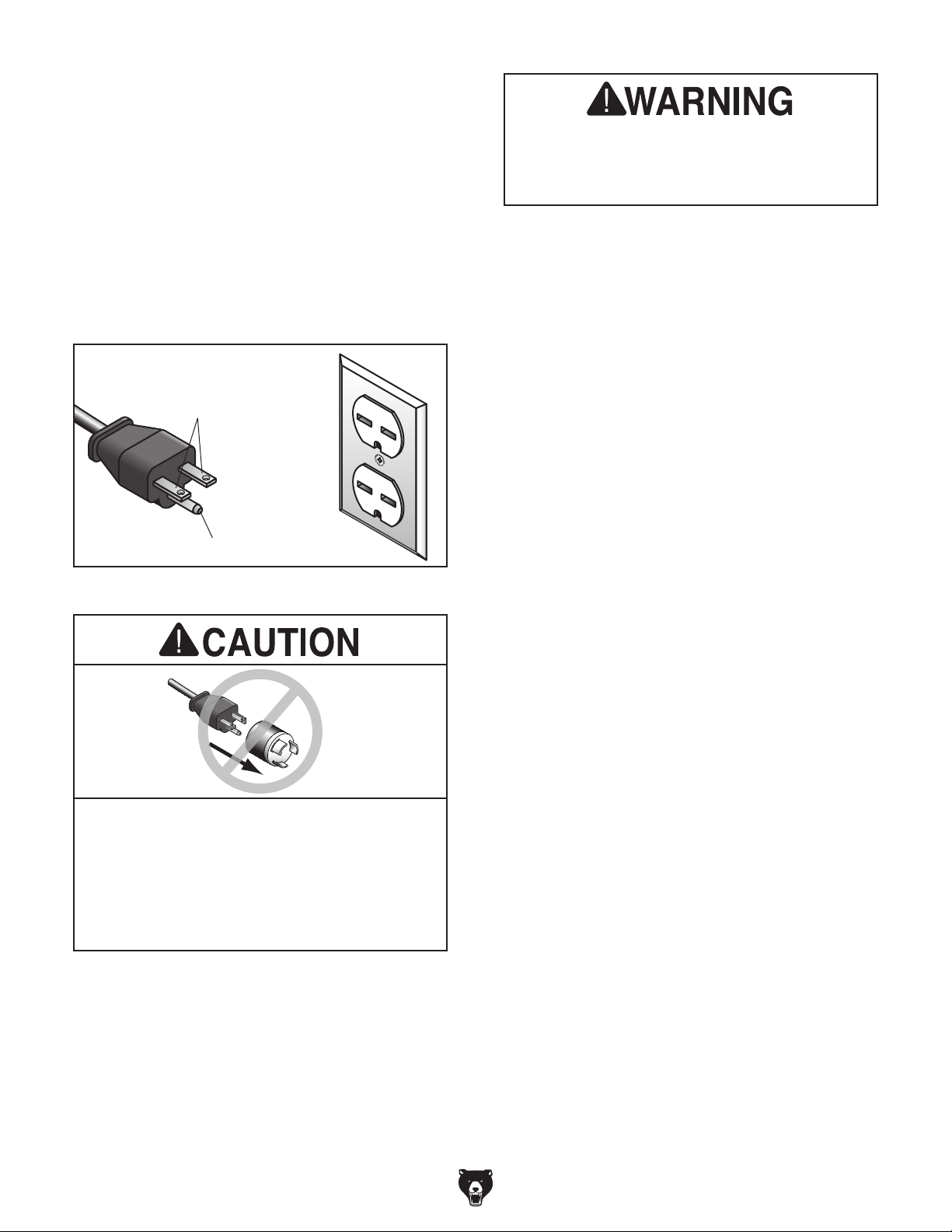
GROUNDED
6-15 RECEPTACLE
Current Carrying Prongs
6-15 PLUG
Serious injury could occur if you connect
the machine to power before completing the
setup process. DO NOT connect to power
until instructed later in this manual.
Grounding Prong
Figure 2. Typical 6-15 plug and receptacle.
No adapter should be used with the plug. If
plug does not fit the available receptacle, or
if machine must be reconnected for use on
a different type of circuit, the reconnection
comply with all local codes and ordinances.
-10 -
Extension Cords
If you must use an extension
Minimum Gauge Size ...........................14 AWG
Maximum Length (Shorter is Better).......50 ft.
Model G0775 (Mfd. Since 11/14)
Page 13

SECTION 3: SETUP
Your machine was carefully packaged for safe
transportation. Remove the packaging materials
from around your machine and inspect it. If you
discover any damage, please call us immediately
at (570) 546-9663
Save the containers and all packing materials for
possible inspection by the carrier or its agent.
Otherwise, filing a freight claim can be difficult.
When you are completely satisfied with the condition of your shipment, inventory the contents.
Keep children and pets away
from plastic bags or packing
materials shipped with this
get help from other people
This machine presents
serious injury hazards
to untrained users. Read
through this entire manual to become familiar with
the controls and operations before starting the
machine!
Wear safety glasses during
the entire setup process!
Unpacking
for advice.
HEAV Y LIFT!
Straining or crushing injury
may occur from improperly
lifting machine or some of
its parts. To reduce this risk,
and use a forklift (or other
lifting equipment) rated for
weight of this machine.
Needed for Setup
The following are needed to complete the setup
process:
Description
• Safety Glasses
• Cleaner/Degreaser
• Disposable Shop Rags
• Forklift
• Dust Collection System
• Dust Hose 4"
• Hose Clamps 4"
SUFFOCATION HAZARD!
machine. Discard immediately.
Model G0775 (Mfd. Since 11/14)
-11-
Page 14

Inventory
The following is a list of items shipped with your
machine. Before beginning setup, lay these items
out and inventory them.
If any non-proprietary parts are missing (e.g. a
nut or a washer), we will gladly replace them; or
for the sake of expediency, replacements can be
obtained at your local hardware store.
Main Components (Figure 3) Qty
A. Sander Assembly ....................................... 1
B. Magnetic Switch Pedestal .......................... 1
C. Miter Gauge ................................................ 1
D. Open-End Wrench 10x13mm (Not Shown) 1
E. Radius Sanding Attachment (Not Shown) . . 1
F. Hex Wrenches 2.5, 5mm (Not Shown) . . 1 Ea
A
C
NOTICE
If you cannot find an item on this list, carefully check around/inside the machine and
packaging materials. Often, these items get
lost in packaging materials while unpacking or they are pre-installed at the factory.
B
Figure 3. Model G0775 inventory.
-12-
Model G0775 (Mfd. Since 11/14)
Page 15

The unpainted surfaces of your machine are
coated with a heavy-duty rust preventative that
prevents corrosion during shipment and storage.
This rust preventative works extremely well, but it
will take a little time to clean.
Be patient and do a thorough job cleaning your
machine. The time you spend doing this now will
give you a better appreciation for the proper care
of your machine's unpainted surfaces.
There are many ways to remove this rust preventative, but the following steps work well in a wide
variety of situations. Always follow the manufacturer’s instructions with any cleaning product you
use and make sure you work in a well-ventilated
area to minimize exposure to toxic fumes.
Before cleaning, gather the following:
• Disposable rags
• Cleaner/degreaser (WD•40 works well)
• Safety glasses & disposable gloves
• Plastic paint scraper (optional)
Basic steps for removing rust preventative:
1.
2.
3.
4.
Many cleaning solvents
work in a well-ventilated
Avoid chlorine-based solvents, such as
Cleanup
Gasoline and petroleum
products have low flash
points and can explode
or cause fire if used to
clean machinery. Avoid
using these products
to clean machinery.
Put on safety glasses.
Coat the rust preventative with a liberal
amount of cleaner/degreaser, then let it soak
for 5–10 minutes.
Wipe off the surfaces. If your cleaner/degreas-
er is effective, the rust preventative will wipe
off easily. If you have a plastic paint scraper,
scrape off as much as you can first, then wipe
off the rest with the rag.
are toxic if inhaled. Only
area.
NOTICE
acetone or brake parts cleaner, that may
damage painted surfaces.
T23692—Orange Power Degreaser
A great product for removing the waxy shipping
grease from your machine during clean up.
Figure 4. T23692 Orange Power Degreaser.
Repeat Steps 2–3 as necessary until clean,
then coat all unpainted surfaces with a quality
metal protectant to prevent rust.
Model G0775 (Mfd. Since 11/14)
-13-
Page 16

Site Considerations
Weight Load
Refer to the
of your machine. Make sure that the surface upon
which the machine is placed will bear the weight
of the machine, additional equipment that may be
installed on the machine, and the heaviest workpiece that will be used. Additionally, consider the
weight of the operator and any dynamic loading
that may occur when operating the machine.
Space Allocation
Consider the largest size of workpiece that will
be processed through this machine and provide
enough space around the machine for adequate
operator material handling or the installation of
auxiliary equipment. With permanent installations,
leave enough space around the machine to open
or remove doors/covers as required by the maintenance and service described in this manual.
See below for required space allocation.
Physical Environment
Extreme conditions for this type of machinery are
Place this machine near an existing power source.
other hazards. Make sure to leave enough space
Shadows, glare, or strobe effects that may distract
or impede the operator must be eliminated.
Machine Data Sheet for the weight
Children or untrained people
may be seriously injured by
this machine. Only install in an
access restricted location.
281/2"
The physical environment where the machine is
operated is important for safe operation and longevity of machine components. For best results,
operate this machine in a dry environment that is
free from excessive moisture, hazardous chemicals, airborne abrasives, or extreme conditions.
generally those where the ambient temperature
range exceeds 41°–104°F; the relative humidity
range exceeds 20%–95% (non-condensing); or
the environment is subject to vibration, shocks,
or bumps.
Electrical Installation
Make sure all power cords are protected from
traffic, material handling, moisture, chemicals, or
around machine to disconnect power supply or
apply a lockout/tagout device, if required.
Lighting
Lighting around the machine must be adequate
enough that operations can be performed safely.
30" Minimum
Figure 5. Minimum working clearances.
-14-
25"
Model G0775 (Mfd. Since 11/14)
Wall
Page 17

Anchoring to Floor
Anchoring machinery to the floor prevents tipping
or shifting and reduces vibration that may occur
during operation, resulting in a machine that runs
slightly quieter and feels more solid.
If the machine will be installed in a commercial or
workplace setting, or if it is permanently connected (hardwired) to the power supply, local codes
may require that it be anchored to the floor.
If not required by any local codes, fastening the
machine to the floor is an optional step. If you
choose not to do this with your machine, we recommend placing it on machine mounts, as these
provide an easy method for leveling and they have
vibration-absorbing pads.
Lag shield anchors with lag screws (see below)
are a popular way to anchor machinery to a concrete floor, because the anchors sit flush with the
floor surface, making it easy to unbolt and move
the machine later, if needed. However, anytime
local codes apply, you MUST follow the anchoring
methodology specified by the code.
Assembly
Number of Mounting Holes ............................ 4
Diameter of Mounting Hardware ................
5
⁄16"
Anchoring to Concrete Floors
The magnetic switch pedestal must be mounted
to the sander to operate the sander.
To mount pedestal:
1. Mount magnetic switch pedestal to sander
with two included M8-1.25 x 45 button head
cap screws and fender washers, as shown in
Figure 7.
Pedestal
x 2
Machine Base
Concrete
Figure 6. Popular method for anchoring
machinery to a concrete floor.
Lag Screw
Flat Washer
Lag Shield Anchor
Drilled Hole
Figure 7. Magnetic switch pedestal mounted.
Model G0775 (Mfd. Since 11/14)
-15-
Page 18

Dust Collection
Once assembly is complete, test run the machine
to ensure it is properly connected to power and
safety components are functioning properly.
If you find an unusual problem during the test run,
immediately stop the machine, disconnect it from
power, and fix the problem BEFORE operating the
machine again. The
table in the
SERVICE section of this manual can help.
setup instructions have been performed.
Operating an improperly set up machine
Serious injury or death can result from
This machine creates substantial amounts
of dust during operation. Breathing airborne dust on a regular basis can result in
permanent respiratory illness. Reduce your
risk by wearing a respirator and capturing
the dust with a dust collection system.
Recommended CFM at Dust Port: 400 CFM
Do not confuse this CFM recommendation with
the rating of the dust collector. To determine the
CFM at the dust port, you must consider these
variables: (1) CFM rating of the dust collector,
(2) hose type and length between the dust collector and the machine, (3) number of branches
or wyes, and (4) amount of other open lines
throughout the system. Explaining how to calculate these variables is beyond the scope of
this manual. Consult an expert or purchase a
good dust collection "how-to" book.
Test Run
Troubleshooting
using this machine BEFORE understanding
its controls and related safety information.
DO NOT operate, or allow others to operate,
machine until the information is understood.
DO NOT start machine until all preceding
To connect a dust collection hose:
1. Fit 4" dust hose over dust port, as shown
in Figure 8, and secure in place with hose
clamp.
Figure 8. Dust hose attached to dust port.
2. Tug hose to make sure it does not come off.
Note: A tight fit is necessary for proper per-
formance.
-16 -
may result in malfunction or unexpected results that can lead to serious injury,
death, or machine/property damage.
To test run machine:
1. Clear all setup tools away from machine.
2. Spin sanding disc by hand to make sure
sandpaper does not touch table.
— If sandpaper touches table, loosen hex
bolts that secure table to support brackets, then follow Steps 3–5 on Page 26 to
adjust table gap.
3. Connect machine to power supply.
4. Turn machine ON, verify motor operation,
and then turn machine OFF.
The motor should run smoothly and without
unusual problems or noises.
Model G0775 (Mfd. Since 11/14)
Page 19

SECTION 4: OPERATIONS
The purpose of this overview is to provide the novice machine operator with a basic understanding
of how the machine is used during operation, so
the
discussed later
in this manual
Due to the generic nature of this overview, it is
not intended to be an instructional guide. To learn
more about specific operations, read this entire
manual and
rienced
research outside of this manual by reading "howto" books, trade magazines, or websites.
To reduce your risk of
serious injury, read this
entire manual BEFORE
To reduce risk of eye injury from flying
Operation Overview
To complete a typical sanding operation, the
operator does the following:
1. Examines workpiece to make sure it is suit-
able for sanding.
machine controls/components
are easier to understand.
seek additional training from expe-
machine operators, and do additional
using machine.
2. Adjusts table tilt if necessary and locks table
in place.
3. If necessary, inserts miter gauge in either
X-axis or Y-axis miter slots, adjusts miter
gauge to required sanding angle, and locks it
in place.
4. Puts on safety glasses and a respirator.
5. Starts machine and dust collector.
6. Holds workpiece firmly and flatly against
both table and miter gauge (if used), pushes
workpiece into or along down-spin side of
sanding disc, and moves it to different locations to wear sandpaper evenly and prevent
it from overheating.
7. Stops machine.
chips or lung damage from breathing dust,
always wear safety glasses and a respirator
when operating this machine.
If you are not experienced with this type
of machine, WE STRONGLY RECOMMEND
that you seek additional training outside of
this manual. Read books/magazines or get
formal training before beginning any projects. Regardless of the content in this section, Grizzly Industrial will not be held liable
for accidents caused by lack of training.
Model G0775 (Mfd. Since 11/14)
-17-
Page 20

Attaching Sandpaper
Disc Sanding
The Model G0775 sander accepts 20" diameter
PSA (pressure-sensitive adhesive) sanding discs.
These are available in a variety of grits. The sandpaper can be replaced without removing the table.
To attach sandpaper:
1. DISCONNECT MACHINE FROM POWER!
2. Loosen six hex bolts that secure table to
support brackets, and move table away from
sanding disc.
3. Remove disc guard, peel off old sandpaper,
clean disc surface with mineral spirits, and
wipe it dry.
4. Peel back protective layer on one-half of
sandpaper disc and fold it against remaining
half.
5. Slip half with protective layer between disc
and the table edge (see Figure 9).
The Model G0775 uses a dual-axis miter slot
design for increased versatility of workpiece control.
Always keep disc guard in place and
workpiece on side of wheel that is rotating
downward. This will reduce likelihood of
workpiece being ejected.
To reduce risk of your fingers getting
trapped between work table and sanding
disc, make sure the table is approximately
1
⁄16" away from sanding disc.
To use sanding disc:
1. DISCONNECT MACHINE FROM POWER!
Figure 9. Installing sandpaper.
6. Position exposed adhesive on upper half of
disc that extends above table. Once it is positioned evenly across disc, press adhesive
onto surface.
7. Rotate disc so lower half is above table. Peel
off other half of protective paper, and press
remaining sandpaper against disc so adhesion is complete.
2. Set angle of table and miter gauge for your
operation.
1
3. Make sure table is about
ing disc. Refer to Table Gap & Parallelism
on Page 26 for further details.
4. Connect sander to power, turn it ON, and
allow it to reach full speed.
5. With disc guard in place, position workpiece
on work table against miter gauge.
⁄16" away from sand-
8. Adjust table gap and parallelism (see Page
26 for further details).
9. Tighten hex bolts and re-install disc guard.
-18-
Model G0775 (Mfd. Since 11/14)
Page 21

6. With moderate pressure, push workpiece into
down-spin side of rotating disc. See Figures
10–13 below for examples of disc sanding.
Figure 13. Example of sanding with table tilted.
Figure 10. Example of Y-axis sanding.
Figure 11. Example of X-axis sanding.
Note: You can use the included radius sanding
attachment to sand round workpieces. Insert the
sanding attachment into the Y-axis. Mark the center of the workpiece with an awl or center punch.
Place the center mark over the pivot point of the
sanding attachment. Spin the workpiece clockwise against the down-spin side of the rotating
disc.
Note: To perform sanding on compound-angle
cuts, tilt the table and rotate the miter gauge to the
appropriate angles.
Note: To prevent burning the workpiece and over-
loading the sanding disc, move the workpiece
slowly back and forth from the left side of the
sanding disc to the center and do not use excessive pressure.
Figure 12. Example of angle sanding.
Model G0775 (Mfd. Since 11/14)
-19 -
Page 22

ACCESSORIES
Installing unapproved accessories may
order online at www.grizzly.com or call 1-800-523-4777
SECTION 5: ACCESSORIES
cause machine to malfunction, resulting in
serious personal injury or machine damage.
To reduce this risk, only install accessories
recommended for this machine by Grizzly.
NOTICE
Refer to our website or latest catalog for
additional recommended accessories.
20" PSA Sanding Discs
Model & Type Grit
D1342 20" PSA ................................................ 60
D1343 20" PSA ................................................ 80
D1344 20" PSA .............................................. 100
D1345 20" PSA .............................................. 120
D1346 20" PSA .............................................. 150
D1347 20" PSA .............................................. 180
D1348 20" PSA .............................................. 220
PRO-STICK® Abrasive Surface Cleaners
Extend the life of your sanding discs and sleeves!
Choose the Pro-Stick
control or without a handle for more usable area.
Size Model
1
⁄2" X 11⁄2" X 81⁄2" .................................... W1306
1
2" X 2" X 12"............................................ W1307
Figure 15. PRO-STICK
D4206—Clear Flexible Hose 4" x 10'
D4216—Black Flexible Hose 4" x 10'
W1034—Heavy-Duty Clear Flex Hose 4" x 10'
D2107—Hose Hanger 4
W1015—Y-Fitting 4" x 4" x 4"
W1017—90° Elbow 4"
W1019—Hose Coupler (Splice) 4"
W1317—Wire Hose Clamp 4"
W1007—Plastic Blast Gate 4"
W1053—Anti-Static Grounding Kit
We've hand picked a selection of commonly used
dust collection components for machines with 4"
dust ports.
®
with a handle for greater
®
abrasive cleaners.
1
⁄4"
Figure 14. Sanding discs.
-20-
D4206
W1317
W1007
Figure 16. Dust collection accessories.
Model G0775 (Mfd. Since 11/14)
D4216
W1053
W1017
Page 23

T26779 3-in-1 Workpiece Support Stand
order online at www.grizzly.com or call 1-800-523-4777
Rotating head features steel roller topped with 8
rolling balls. Adjusts in height from 271⁄2" to 43".
Unit folds for easy storage. Features heavy-duty
steel frame, four outrigger legs for stability, adjustable foot for uneven floors, and 250 lb. capacity.
Figure 17. T26779 3-in-1 Roller Stand.
H2499—Small Half-Mask Respirator
H3631—Medium Half-Mask Respirator
H3632—Large Half-Mask Respirator
H3635—Cartridge Filter Pair P100
Wood dust has been linked to nasal cancer and
severe respiratory illnesses. If you work arounddust everyday, a half-mask respirator can be a
lifesaver. Also compatible with safety glasses!
Basic Eye Protection
T20501—Face Shield Crown Protector 4"
T20502—Face Shield Crown Protector 7"
T20503—Face Shield Window
T20451—“Kirova” Clear Safety Glasses
T20452—“Kirova” Anti-Reflective S. Glasses
H7194—Bifocal Safety Glasses 1.5
H7195—Bifocal Safety Glasses 2.0
H7196—Bifocal Safety Glasses 2.5
T20502
T20452
T20503
H7194
T20451
Figure 19. Half-mask respirator with disposable
cartridge filters.
Basic Hearing Protection
H4978—Deluxe Earmuffs - 27dB
H4979—Twin Cup Hearing Protector - 29dB
T20446—Ear Plugs 200 Pair - 31dB
A must have if you or employees operate for hours
at a time.
H4978
T20446
H4979
Figure 18. Assortment of basic eye protection.
Model G0775 (Mfd. Since 11/14)
Figure 20. Hearing protection assortment.
-21-
Page 24

®
order online at www.grizzly.com or call 1-800-523-4777
D2057A—Heavy-Duty Shop Fox
Mobile Base
This patented base is the most stable on the market with outrigger type supports. Adjusts from 20"
1
⁄2" to 291⁄2" x 291⁄2". 700 lb. capacity. Weighs
x 20
34 lbs.
Figure 21. D2057A Shop Fox Mobile Base.
G1163P—1HP Floor Model Dust Collector
G0710—1HP Wall-Mount Dust Collector
G3591—30 Micron Replacement Bag
H4340—3.0 Micron Upgrade Bag
Excellent point-of-use dust collectors that can
be used next to the machine with only a small
amount of ducting. Specifications: 450 CFM, 7.2"
static pressure, 2 cubic foot bag, and 30 micron
filter. Motor is 1HP, 120V/240V, 7A /3.5A.
Model G0710
Model G1163P
Figure 22. Point-of-use dust collectors.
-22-
Model G0775 (Mfd. Since 11/14)
Page 25

SECTION 6: MAINTENANCE
accidental startup, always
disconnect machine from
Cleaning &
To reduce risk of shock or
power before adjustments,
maintenance, or service.
Schedule
For optimum performance from your machine,
follow this maintenance schedule and refer to any
specific instructions given in this section.
Daily Check
• Loose mounting bolts.
• Damaged or worn sandpaper.
• Worn or damaged wires.
• Any other unsafe condition.
Weekly/Monthly Check
• Vacuum dust off motor fan.
Protecting
Cleaning the Model G0775 is relatively easy.
Vacuum excess wood chips and sawdust, and
wipe off the remaining dust with a dry cloth. If any
resin has built up, use a resin dissolving cleaner
to remove it.
Protect the unpainted cast iron table by wiping
it clean after every use—this ensures moisture
from wood dust does not remain on bare metal
surfaces. Keep the table rust-free with regular
applications of products like G96
SLIPIT
G5562—SLIPIT
G5563—SLIPIT
G2871—Boeshield
G2870—Boeshield
H3788—G96
H3789—G96
®
, or Boeshield® T-9.
®
1 Qt. Gel
®
12 Oz. Spray
®
T-9 12 Oz. Spray
®
®
Gun Treatment 12 Oz. Spray
®
Gun Treatment 4.5 Oz. Spray
T-9 4 Oz. Spray
®
Gun Treatment,
Model G0775 (Mfd. Since 11/14)
Figure 23. Recommended products for protecting unpainted cast iron/steel part on machinery.
-23-
Page 26

Review the troubleshooting and procedures in this section if a problem develops with your machine. If you
need replacement parts or additional help with a procedure, call our Technical Support at (570) 546-9663.
Note: Please gather the serial number and manufacture date of your machine before calling.
SECTION 7: SERVICE
Troubleshooting
Motor & Electrical
Symptom Possible Cause Possible Solution
Machine does not
start or a circuit
breaker trips.
Machine stalls or is
underpowered.
Machine has
vibration or noisy
operation.
Motor takes longer
than 4 seconds to
stop sanding disc.
1. Incorrect power supply voltage or circuit
size.
2. Power supply circuit breaker tripped or fuse
blown.
3. Motor wires connected incorrectly.
4. Wiring open/has high resistance.
5. ON/OFF switch at fault.
6. Start capacitor at fault.
7. Thermal overload relay has tripped.
8. Contactor not energized/has poor contacts.
9. Centrifugal switch at fault.
10. Motor at fault.
1. Machine undersized for task.
2. Motor wired incorrectly.
3. Motor overheated.
4. Run capacitor at fault.
5. Contactor not energized/has poor contacts.
6. Motor at fault.
1. Workpiece loose or incorrectly secured.
2. Table or switch pedestal mounting bolts
loose.
3. Table contacting sanding disc.
4. Motor or component loose.
5. Motor fan rubbing on fan cover.
6. Motor mount loose/broken.
7. Machine incorrectly mounted.
8. Motor bearings at fault.
9. Sanding disc out of balance or loose.
10. Centrifugal switch is at fault.
1. Motor brake components at fault. 1. Replace motor brake components. Call Tech
1. Ensure correct power supply voltage and circuit
size.
2. Ensure circuit is sized correctly and free of shorts.
Reset circuit breaker or replace fuse.
3. Correct motor wiring connections.
4. Check/fix broken, disconnected, or corroded wires.
5. Replace switch.
6. Test/replace.
7. Reset; adjust trip load dial if necessary; replace.
8. Test all legs for power/replace.
9. Adjust/replace centrifugal switch if available.
10. Test/repair/replace.
1. Clean/replace sandpaper; reduce feed rate/sanding
depth.
2. Wire motor correctly.
3. Clean motor, let cool, and reduce workload.
4. Test/repair/replace.
5. Test all legs for power/replace.
6. Test/repair/replace.
1. Use correct holding fixture and reclamp workpiece.
2. Tighten mounting bolts.
3. Adjust table gap (Page 26).
4. Inspect/replace damaged bolts/nuts, and retighten
with thread locking fluid.
5. Fix/replace fan cover; replace loose/damaged fan.
6. Tighten/replace.
7. Tighten mounting bolts; relocate/shim machine.
8. Test by rotating shaft; rotational grinding/loose shaft
requires bearing replacement.
9. Tighten disc hub or replace disc.
10. Replace.
Support if you need assistance.
-24-
Model G0775 (Mfd. Since 11/14)
Page 27

Sander Operation
Symptom Possible Cause Possible Solution
Miter bar binds in
miter slot.
Workpiece angle
incorrect or out of
square.
Sandpaper clogs
quickly or burns.
Glossy spots, burning, or streaks on
workpiece.
Abrasive rubs off
the disc easily.
1. Miter slot dirty or gummed up. 1. Carefully clean miter slot.
1. Pointer or scale not calibrated correctly.
Miter gauge or table not correctly aligned.
1. Sandpaper grit is too fine for the job.
2. Workpiece is too moist.
3. Sanding pressure/depth too aggressive.
4. Paint, varnish, pitch, or other coating is
loading up sandpaper.
5. Sanding soft workpiece.
6. Work held still for too long.
1. Sandpaper too fine for the desired finish.
2. Work held still for too long.
3. Workpiece is too moist.
4. Sanding stock with high residue.
5. Worn sandpaper.
6. Sanding depth too aggressive.
1. Sandpaper has been stored in an incorrect
environment.
1. Adjust pointer or scale to reflect real path of cut
(Page 26, 27).
1. Replace with a coarser grit sandpaper.
2. Allow workpiece to dry out.
3. Reduce sanding pressure/depth or install coarser
sandpaper.
4. Install a coarse grit sandpaper, or strip coating off
before sanding.
5. Use different stock. Or, accept the characteristics
of the stock and plan on cleaning/replacing discs
frequently.
6. Move workpiece more frequently.
1. Use a coarser grit sandpaper.
2. Do not keep workpiece in one place for too long.
3. Allow workpiece to dry out.
4. Use different stock. Or, accept the characteristics
of the stock and plan on cleaning/replacing
sandpapers frequently.
5. Replace sandpaper (Page 18).
6. Reduce sanding depth or install coarser sandpaper.
1. Replace; store sandpaper away from extremely dry,
hot, or damp conditions.
Model G0775 (Mfd. Since 11/14)
-25-
Page 28

Table Gap &
Calibrating Miter
Parallelism
The miter slot must be parallel with the face of the
sanding disc. There should be a
the edge of the table and sanding disc to prevent
the sandpaper from rubbing against the table, and
to reduce risk of fingers getting pinched.
Tools Needed:
Open-End Wrench 13mm .................................. 1
Ruler .................................................................. 1
To set table gap and parallelism:
1. DISCONNECT MACHINE FROM POWER!
2. Remove guard, then loosen the six hex bolts
that secure table to table support brackets.
3. Adjust table so there is a
24) between disc (with sandpaper installed)
and edge of table along its full length.
1
⁄16" gap between
1
⁄16'' gap (see Figure
Gauge
At 90˚, the miter gauge should be perpendicular
to the face of the disc when it is mounted in the
X-axis table slot. If it is not, follow this procedure
to recalibrate it.
Tools Needed:
90° Square Square ............................................ 1
Phillips Head Screwdriver .................................. 1
To calibrate miter gauge:
1. DISCONNECT MACHINE FROM POWER!
2. Check that miter slot is parallel to sanding disc
as described in Table Gap & Parallelism.
3. Set one edge of a try square or 90° square
against face of miter gauge and other edge
against disc face, as shown in Figure 25.
1
⁄16"
Sanding Disc
Table
Figure 24. Table parallel with sanding disc.
4. When miter slot is parallel with sanding disc,
tighten hex bolts.
5. Spin disc by hand to check if sandpaper
touches table.
IMPORTANT: DO NOT turn the disc sander
ON until you have verified that it does not
touch the table at any point in its rotation!
— If sandpaper touches table at any point,
re-adjust table parallelism.
(Top View)
Figure 25. Squaring miter gauge to disc.
4. Loosen lock knob on miter gauge and adjust
face of miter gauge so it is flush with edge of
square, tighten gauge lock knob, and verify
setting.
5. Loosen degree scale pointer, position pointer
on 90˚, and retighten screw.
6. Recheck miter scale accuracy with square.
6. Re-install guard.
-26-
Model G0775 (Mfd. Since 11/14)
Page 29

Table Tilt Calibration
When the table is perpendicular to the sanding
disc, the scale should read 0˚. If not, follow this
procedure.
Tools Needed:
90° Square ........................................................ 1
45° Square ..........................................................
Phillips Head Screwdriver .................................. 1
Hex Wrench 5mm .............................................. 1
5. Loosen degree scale pointer screw (see
Figure 27), adjust pointer to 0˚, then retight-
en screw.
Calibrating Table Tilt
1. DISCONNECT MACHINE FROM POWER!
2. Set one edge of a try square or 90° square on
table surface and the other edge against face
of disc, as shown in Figure 26.
Note: Although this can be done with the
sandpaper installed, it is more precise without it.
45°
Stop
Knob
Hex Nut
90°
Stop
Screw
Scale
Pointer
Figure 27. Scale pointer screw location.
6. Recheck scale accuracy with square.
Calibrating 45° Stop
1. DISCONNECT MACHINE FROM POWER!
2. Loosen lock handles and allow table to rest
on 45° stop knob.
3. Set one edge of a 45° square on table surface and other edge against face of disc.
4. Adjust 45° stop knob (shown in Figure 26)
until table angle is exactly 45° to disc, then
tighten hex nut under 45° stop knob against
sander frame.
Figure 26. Squaring table.
3. Loosen lock handles, then adjust 90° stop
screw (see Figure 26) until table angle is
perfectly perpendicular to disc.
4. Tighten lock handles while holding table in
place.
Model G0775 (Mfd. Since 11/14)
-27-
Page 30

These pages are current at the time of printing. However, in the spirit of improvement, we may make changes to the electrical systems of future machines. Compare the manufacture date of your machine to the one
number and manufacture date of your
machine before calling. This information can be found on the main machine label.
machine
SECTION 8: WIRING
stated in this manual, and study this section carefully.
If there are differences between your machine and what is shown in this section, call Technical Support at
(570) 546-9663 for assistance BEFORE making any changes to the wiring on your machine. An updated
wiring diagram may be available. Note: Please gather the serial
Wiring Safety Instructions
SHOCK HAZARD. Working on wiring that is con-
nected to a power source is extremely dangerous.
Touching electrified parts will result in personal
injury including but not limited to severe burns,
electrocution, or death. Disconnect the power
from the machine before servicing electrical components!
MODIFICATIONS. Modifying the wiring beyond
what is shown in the diagram may lead to unpredictable results, including serious injury or fire.
This includes the installation of unapproved aftermarket parts.
WIRE CONNECTIONS. All connections must
be tight to prevent wires from loosening during
machine operation. Double-check all wires disconnected or connected during any wiring task to
ensure tight connections.
CIRCUIT REQUIREMENTS. You MUST follow
the requirements at the beginning of this manual
when connecting your machine to a power source.
WIRE/COMPONENT DAMAGE. Damaged wires
or components increase the risk of serious personal injury, fire, or machine damage. If you notice
that any wires or components are damaged while
performing a wiring task, replace those wires or
components.
MOTOR WIRING. The motor wiring shown in
these diagrams is current at the time of printing
but may not match your machine. If you find this
to be the case, use the wiring diagram inside the
motor junction box.
CAPACITORS/INVERTERS. Some capacitors
and power inverters store an electrical charge for
up to 10 minutes after being disconnected from
the power source. To reduce the risk of being
shocked, wait at least this long before working on
capacitors.
EXPERIENCING DIFFICULTIES. If you are experiencing difficulties understanding the information
included in this section, contact our Technical
Support at (570) 546-9663.
The photos and diagrams
included in this section are
best viewed in color. You
can view these pages in
color at www.grizzly.com.
-28-
Model G0775 (Mfd. Since 11/14)
Page 31

Electrical Components
Figure 29. Start capacitor.
Figure 28. Magnetic switch.
Run
Capacitor
Motor Brake
Ballast
Figure 30. Motor junction box components.
Model G0775 (Mfd. Since 11/14)
READ ELECTRICAL SAFETY
ON PAGE 28!
-29-
Page 32

Magnetic Switch
NHD MS1-09D
Wiring Diagram
A1
1L1 5L3
2T1 6T3
9
10
11
98 96
3L2
Contactor
NHD C-09D
220V
4T2
8
97
13NO
18
14NO
OL Relay
NHD NTH-11
O R
6T34T22T1
A2
17
GND
A2
The motor wiring shown here is
current at the time of printing, but it
may not match your machine.
Always use the wiring diagram
inside the motor junction box.
S Capacitor
150MFD
95
250VAC
Motor
Brake
Rectifier
Ballast
R Capacitor
30MFD
350VAC
220V Motor
220 VAC
6-15 Plug
-30-
Ground
G
Hot
Hot
READ ELECTRICAL SAFETY
ON PAGE 28!
GND
Model G0775 (Mfd. Since 11/14)
Page 33

SECTION 9: PARTS
Please Note: We do our best to stock replacement parts whenever possible, but we cannot guarantee that all parts shown here
are available for purchase. Call (800) 523 -4777 or visit our online parts store at www.grizzly.com to check for availability.
Main Breakdown
20
21
49
48
17
8
39
21
19
4-4
4-7
4-1
11
28
4-8
36
4-2
4-5
4-10
6
29
10
34
35
4-3
4-6
4-9
4-11
9
23
4-20
4-19
4-18
4-17
39
34
42
4-16
40
27
26
43
30
4-12
4-13
4-14
4-15
44
40
39
13
22
25
47
24
38
19
4
19
3
19
24
15
2
27
40
39
45
33
46
14
18
15-3
12
16
15-1
15-3
15-4
15-2
31
32
1
37
23
35
28
29
7
5
39
37
19
20
Model G0775 (Mfd. Since 11/14)
-31-
Page 34

Main Parts List
REF PART # DESCRIPTION REF PART # DESCRIPTION
1 P0775001 BASE 15-2 P0775015-2 OL RELAY NHD NTH-11 8-11A
2 P0775002 DISC COVER 15-3 P0775015-3 MAG SWITCH COVER ASSY
3 P0775003 MOTOR BASE 15-4 P0775015-4 MAG SWITCH COVER SCREW
4 P0775004 MOTOR 2HP 220V 1-PH 16 P0775016 BUTTON HD CAP SCR M8-1.25 X 35
4-1 P0775004-1 MOTOR FAN COVER 17 P0775017 POINTER
4-2 P0775004-2 MOTOR FAN 18 P0775018 FENDER WASHER 8MM
4-3 P0775004-3 CAPACITOR COVER 19 P0775019 FLAT WASHER 8MM
4-4 P0775004-4 S CAPACITOR 150M 250V 1-3/4 X 3-1/2 20 P0775020 ADJUSTABLE HANDLE M8-1.25 X 25
4-5 P0775004-5 R CAPACITOR 30M 350V 1-1/2 X 2-1/2 21 P0775021 PHLP HD SCR M5-.8 X 8
4-6 P0775004-6 CONTACT PLATE 22 P0775022 CAP SCREW M6-1 X 30
4-7 P0775004-7 MOTOR JUNCTION BOX 23 P0775023 BUTTON HD CAP SCR M8-1.25 X 25
4-8 P0775004-8 CENTRIFUGAL SWITCH 24 P0775024 HEX NUT M8-1.25
4-9 P0775004-9 BALL BEARING 6203ZZ 25 P0775025 KNOB M8-1.25 X 40
4-10 P0775004-10 REGULATOR SWITCH 26 P0775026 FLEXIBLE HOSE 4" X 22-7/8"
4-11 P0775004-11 BALL BEARING 6204ZZ 27 P0775027 HOSE CLAMP 4"
4-12 P0775004-12 COMPRESSION SPRING 28 P0775028 LOCK NUT M8-1.25
4-13 P0775004-13 SPACER 29 P0775029 FLAT WASHER 8MM PLASTIC
4-14 P0775004-14 BRAKE PAD 30 P0775030 MITER GAUGE ASSY
4-15 P0775004-15 SHOULDER SCREW M5-.8 X 25, 8 X 35 BLK 31 P0775031 POWER CORD 14G 3W 72" 6-15P
4-16 P0775004-16 CAP SCREW M6-1 X 30 SS 32 P0775032 STRAIN RELIEF 5/16"-3/8" 90D PLASTIC
4-17 P0775004-17 FLAT WASHER 6MM 33 P0775033 MOTOR CORD 14G 3W 25"
4-18 P0775004-18 OUTSIDE PLATE 34 P0775034 SET SCREW M8-1.25 X 15
4-19 P0775004-19 INSIDE PLATE 35 P0775035 LOCK WASHER 8MM
4-20 P0775004-20 MOTOR BRAKE MCN CB-08-CS DC-90V 36 P0775036 CAP SCREW M8-1.25 X 35
5 P0775005 TABLE BRACKET (R) 37 P0775037 HEX BOLT M8-1.25 X 20
6 P0775006 TABLE BRACKET (L) 38 P0775038 HEX BOLT M8-1.25 X 25
7 P0775007 TABLE 39 P0775039 FLAT WASHER 8MM
8 P0775008 DISC GUARD 40 P0775040 BUTTON HD CAP SCR M8-1.25 X 16
9 P0775009 DISC PLATEN 20" 42 P0775042 RADIUS SANDING ATTACHMENT
10 P0775010 FLANGE WASHER 8MM 43 P0775043 SET SCREW M5-.8 X 10 CONE-PT
11 P0775011 SANDING DISC 20" 100-GRIT PSA 44 P0775044 SET SCREW M5-.8 X 8 DOG-PT
12 P0775012 SWITCH PEDESTAL 45 P0775045 DOOR LATCH
13 P0775013 DUST COLLECTION HOOD 46 P0775046 DOOR
14 P0775014 PLASTIC CAP 50 X 25MM 47 P0775047 FLAT WASHER 30 X 65MM RUBBER
15 P0775015 MAG SWITCH ASSY NHD MS1-09D 48 P0775048 FLAT WASHER #10
15-1 P0775015-1 CONTACTOR NHD C-09D 49 P0775049 EXT TOOTH WASHER 5MM
-32-
Model G0775 (Mfd. Since 11/14)
Page 35

Labels and Cosmetics
55
54
53
51
52
58
56
57
50
REF PART # DESCRIPTION REF PART # DESCRIPTION
50 P0775050 GRIZZLY.COM LABEL 55 P0775055 SAFETY GUARD WARNING LABEL
51 P0775051 MODEL NUMBER LABEL 56 P0775056 ROTATION WARNING LABEL
52 P0775052 GRIZZLY NAMEPLATE SMALL G8588 57 P0775057 ELECTRICITY LABEL
53 P0775053 MACHINE ID LABEL 58 P0775058 GRIZZLY GREEN TOUCH-UP PAINT
Safety labels help reduce the risk of serious injury caused by machine hazards. If any label comes
off or becomes unreadable, the owner of this machine MUST replace it in the original location
before resuming operations. For replacements, contact (800) 523-4777 or www.grizzly.com.
Model G0775 (Mfd. Since 11/14)
-33-
Page 36

Page 37

WARRANTY CARD
Name _____________________________________________________________________________
Street _____________________________________________________________________________
City _______________________ State _________________________ Zip _____________________
Phone # ____________________ Email _________________________________________________
Model # ____________________ Order # _______________________ Serial # __________________
The following information is given on a voluntary basis. It will be used for marketing purposes to help us develop
better products and services. Of course, all information is strictly confidential.
1. How did you learn about us?
____ Advertisement ____ Friend ____ Catalog
____ Card Deck ____ Website ____ Other:
2. Which of the following magazines do you subscribe to?
____ Cabinetmaker & FDM
____ Family Handyman
____ Hand Loader
____ Handy
____ Home Shop Machinist
____ Journal of Light Cont.
____ Live Steam
____ Model Airplane News
____ Old House Journal
____ Popular Mechanics
3. What is your annual household income?
____ $20,000-$29,000 ____ $30,000-$39,000 ____ $40,000-$49,000
____ $50,000-$59,000 ____ $60,000-$69,000 ____ $70,000+
CUT ALONG DOTTED LINE
4. What is your age group?
____ 20-29 ____ 30-39 ____ 40-49
____ 50-59 ____ 60-69 ____ 70+
5. How long have you been a woodworker/metalworker?
____ 0-2 Years ____ 2-8 Years ____ 8-20 Years ____20+ Years
6. How many of your machines or tools are Grizzly?
____ 0-2 ____ 3-5 ____ 6-9 ____ 10+
____ Popular Science
____ Popular Woodworking
____ Precision Shooter
____ Projects in Metal
____ RC Modeler
____ Rie
____ Shop Notes
____ Shotgun News
____ Today’s Homeowner
____ Wood
____ Wooden Boat
____ Woodshop News
____ Woodsmith
____ Woodwork
____ Woodworker West
____ Woodworker’s Journal
____ Other:
7. Do you think your machine represents a good value? _____ Yes _____No
8. Would you recommend Grizzly Industrial to a friend? _____ Yes _____No
9. Would you allow us to use your name as a reference for Grizzly customers in your area?
Note: We never use names more than 3 times. _____Yes _____No
10. Comments: _____________________________________________________________________
_________________________________________________________________________________
_________________________________________________________________________________
_________________________________________________________________________________
Page 38

FOLD ALONG DOTTED LINE
FOLD ALONG DOTTED LINE
Place
Stamp
Here
GRIZZLY INDUSTRIAL, INC.
P.O. BOX 2069
BELLINGHAM, WA 98227-2069
Send a Grizzly Catalog to a friend:
Name_______________________________
Street_______________________________
City______________State______Zip______
TAPE ALONG EDGES--PLEASE DO NOT STAPLE
Page 39

WARRANTY & RETURNS
Grizzly Industrial, Inc. warrants every product it sells for a period of 1 year to the original purchaser from
the date of purchase. This warranty does not apply to defects due directly or indirectly to misuse, abuse,
negligence, accidents, repairs or alterations or lack of maintenance. This is Grizzly’s sole written warranty
and any and all warranties that may be implied by law, including any merchantability or fitness, for any particular purpose, are hereby limited to the duration of this written warranty. We do not warrant or represent
that the merchandise complies with the provisions of any law or acts unless the manufacturer so warrants.
In no event shall Grizzly’s liability under this warranty exceed the purchase price paid for the product and
any legal actions brought against Grizzly shall be tried in the State of Washington, County of Whatcom.
We shall in no event be liable for death, injuries to persons or property or for incidental, contingent, special,
or consequential damages arising from the use of our products.
To take advantage of this warranty, contact us by mail or phone and give us all the details. We will then issue
you a “Return Number,’’ which must be clearly posted on the outside as well as the inside of the carton. We
will not accept any item back without this number. Proof of purchase must accompany the merchandise.
The manufacturers reserve the right to change specifications at any time because they constantly strive to
achieve better quality equipment. We make every effort to ensure that our products meet high quality and
durability standards and we hope you never need to use this warranty.
Please feel free to write or call us if you have any questions about the machine or the manual.
Thank you again for your business and continued support. We hope to serve you again soon.
Page 40

 Loading...