

Grizzly G0772 Owner's Manual

MODEL G0772
14" SLIDING TABLE SAW
OWNER'S MANUAL
(For models manufactured since 05/15)
COPYRIGHT © MAY, 2015 BY GRIZZLY INDUSTRIAL, INC., REVISED DECEMBER, 2017 (HE)
WARNING: NO PORTION OF THIS MANUAL MAY BE REPRODUCED IN AN Y SHAPE
OR FORM WITHOUT THE WRITTEN APPROVAL OF GRIZZLY INDUSTRIAL, INC.
#BBBLMNWK17287 PRINTED IN TAIWAN
V1.1 2 .17

This manual provides critical safety instructions on the proper setup,
operation, maintenance, and service of this machine/tool. Save this
document, refer to it often, and use it to instruct other operators.
Failure to read, understand and follow the instructions in this manual
may result in fire or serious personal injury—including amputation,
electrocution, or death.
The owner of this machine/tool is solely responsible for its safe use.
This responsibility includes but is not limited to proper installation in
a safe environment, personnel training and usage authorization,
proper inspection and maintenance, manual availability and comprehension, application of safety devices, cutting/sanding/grinding tool
integrity, and the usage of personal protective equipment.
The manufacturer will not be held liable for injury or property damage
from negligence, improper training, machine modifications or misuse.
Some dust created by power sanding, sawing, grinding, drilling, and
other construction activities contains chemicals known to the State
of California to cause cancer, birth defects or other reproductive
harm. Some examples of these chemicals are:
• Lead from lead-based paints.
• Crystalline silica from bricks, cement and other masonry products.
• Arsenic and chromium from chemically-treated lumber.
Your risk from these exposures varies, depending on how often you
do this type of work. To reduce your exposure to these chemicals:
Work in a well ventilated area, and work with approved safety equipment, such as those dust masks that are specially designed to filter
out microscopic particles.

Table of Contents
INTRODUCTION ............................................... 2
Contact Info.................................................... 2
Manual Accuracy ........................................... 2
Identification ................................................... 3
Controls & Components ................................. 4
Glossary Of Terms ......................................... 7
Sliding Table Saw Capacities ........................ 8
Machine Data Sheet ...................................... 9
SECTION 1: SAFETY ..................................... 12
Safety Instructions for Machinery ................ 12
Additional Safety for Sliding Table Saws ..... 14
Preventing Kickback .................................... 15
Protecting Yourself From Kickback.............. 15
SECTION 2: POWER SUPPLY ...................... 16
440V Conversion ......................................... 18
SECTION 3: SETUP ....................................... 19
Needed for Setup ......................................... 19
Unpacking .................................................... 19
Hardware Recognition Chart ....................... 20
Inventory ...................................................... 21
Cleanup ........................................................ 23
Site Considerations ...................................... 24
Lifting & Placing Saw ................................... 25
Assembly ..................................................... 26
Dust Collection ............................................. 36
Power Connection........................................ 37
Test Run ...................................................... 38
Recommended Adjustments ........................ 40
SECTION 4: OPERATIONS ........................... 41
Operation Overview ..................................... 41
Workpiece Inspection................................... 42
Through & Non-Through Cuts ..................... 42
Blade Guard ................................................. 43
Riving Knife .................................................. 44
Blade Requirements .................................... 46
Blade Selection ............................................ 46
Changing Blade Angle ................................. 47
Changing Blade Height ................................ 48
Changing Blade Speed ................................ 48
Changing Main Blade .................................. 49
Replacing & Aligning Scoring Blade ............ 51
Setting Up Crosscut Fence .......................... 53
Rip Cutting ................................................... 55
Crosscutting ................................................. 57
Miter Cutting................................................. 59
Dado Cutting ................................................ 61
Rabbet Cutting ............................................. 62
Resawing ..................................................... 63
SECTION 5: SHOP MADE SAFETY
ACCESSORIES .............................................. 65
Featherboards .............................................. 65
Push Sticks .................................................. 68
Push Blocks ................................................. 69
Narrow-Rip Auxiliary Fence & Push Block .. 70
SECTION 6: AFTERMARKET
ACCESSORIES FROM GRIZZLY .................. 72
SECTION 7: MAINTENANCE ......................... 75
Schedule ...................................................... 75
Cleaning & Protecting .................................. 75
Lubrication ................................................... 76
SECTION 8: SERVICE ................................... 77
Troubleshooting ........................................... 77
Belt Service .................................................. 79
Blade Tilt Calibration .................................... 80
Sliding Table Parallel Adjustment ................ 82
Calibrating Rip Fence .................................. 83
Squaring Crosscut Fence to Blade .............. 84
SECTION 9: WIRING ...................................... 86
Wiring Safety Instructions ............................ 86
Electrical Overview ...................................... 87
Relay Logic Diagram ................................... 88
Control Panel Wiring .................................... 89
220V Electrical Panel Schematic ................. 90
Main Motor Wiring ........................................ 92
Scoring Motor Wiring ................................. 93
DC Motor Schematic ................................. 94
Linear Actuator Wiring ............................... 95
Belt Speed Rotary Switch Wiring ................. 95
SECTION 10: PARTS ..................................... 96
Body ............................................................. 96
Tables .......................................................... 98
Blade Enclosure ........................................... 99
Main Blade Motor & Arbor ......................... 101
Blade Tilt System ....................................... 103
Scoring Blade Motor & Arbor ..................... 104
Crosscut Table Swing Arm ........................ 106
Crosscut Table ........................................... 107
Crosscut Fence .......................................... 108
Rip Fence................................................... 109
Sliding Table .............................................. 110
Blade Guard ............................................... 112
Blade Guard Arms ..................................... 113
Miter Fence ................................................ 114
Electrical Panel .......................................... 115
Labels & Cosmetics ................................... 116
Accessories ................................................ 117
WARRANTY & RETURNS ........................... 121

INTRODUCTION
We are proud to provide a high-quality owner’s
manual with your new machine!
We
instructions, specifications, drawings, and photographs
in this manual. Sometimes we make mistakes, but
our policy of continuous improvement also means
that
you receive is
slightly different than shown in the manual
If you find this to be the case, and the difference
between the manual and machine leaves you
confused or unsure about something
check our
website for an updated version. W
current
manuals and
on our web-
site at
Alternatively, you can call our Technical Support
for help. Before calling, make sure you write down
the
from
the machine ID label (see below). This information
is required for us to provide proper tech support,
and it helps us determine if updated documentation is available for your machine.
We stand behind our machines! If you have questions or need help, contact us with the information
below. Before contacting, make sure you get the
serial number
machine ID label. This will help us help you faster.
We want your feedback on this manual. What did
you like about it? Where could it be improved?
Please take a few minutes to give us feedback.
Email: manuals@grizzly.com
Contact Info
and manufacture date from the
Grizzly Technical Support
1815 W. Battlefield
Springfield, MO 65807
Phone: (570) 546-9663
Email: techsupport@grizzly.com
Grizzly Documentation Manager
P.O. Box 2069
Bellingham, WA 98227-2069
Manual Accuracy
made every effort to be exact with the
sometimes the machine
.
,
e post
manual updates for free
www.grizzly.com.
Manufacture Date and Serial Number
Manufacture Date
Serial Number
-2-
Model G0772 (Mfd. Since 05/15)
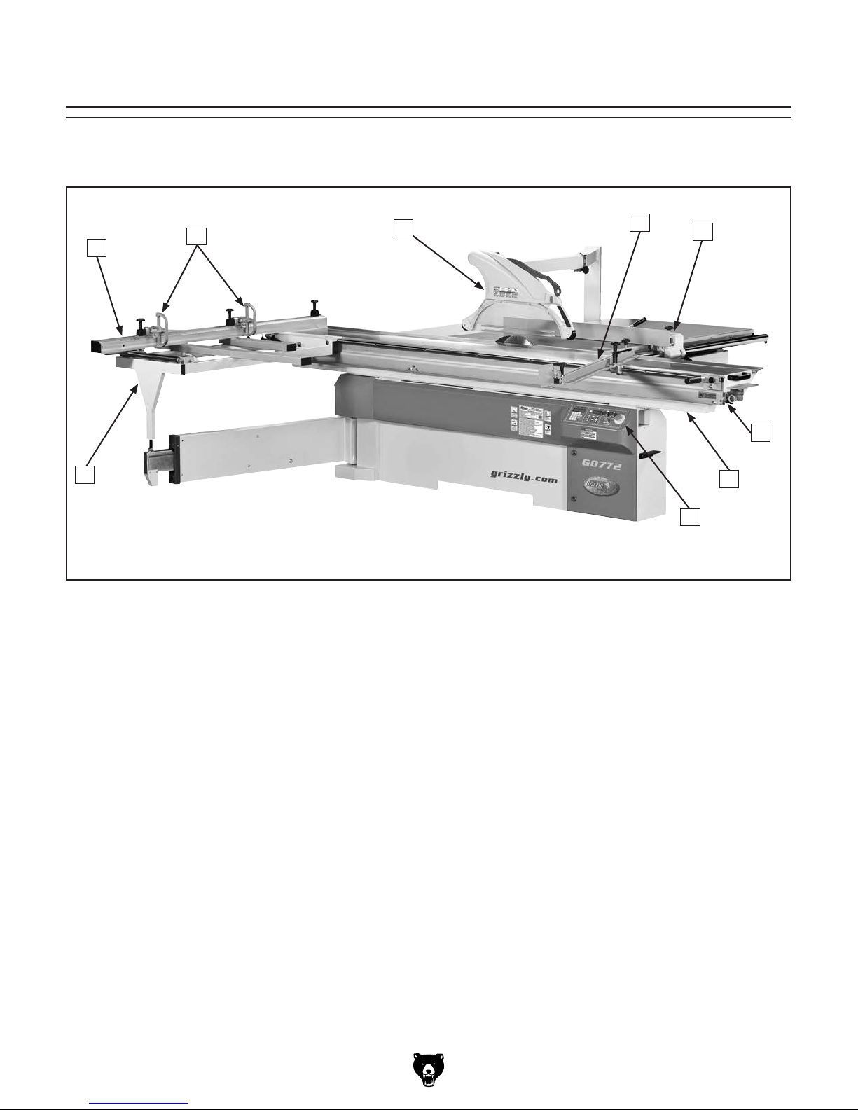
Identification
Become familiar with the names and locations of the controls and components shown below to better
understand the instructions in this manual.
B
C
A
A. Crosscut Table. Provides a wide, stable
platform for supporting full-size panels during
crosscutting operations.
B. Crosscut Fence. Used during crosscutting
operations to keep panels at 90˚ angle to
blade. Features a scale and flip stops.
C. Flip Stops. Used for quick, precise measure-
ments for repeatable cuts when using crosscutting fence.
D. Blade Guard. Fully-enclosed, adjustable
blade guard maintains maximum protection
around saw blade with a 3" dust port that
effectively extracts dust from cutting operation.
D
F. Rip Fence. Fully-adjustable with micro-adjust
knob for precision cuts. Fence face can be
positioned for standard cutting operations, or
placed in lower position for blade guard clearance during narrow ripping operations.
G. Sliding Table Lever. Allows sliding table to
be locked in stationary position. Push down
to release; pull up to lock.
H. Sliding Table. Ball-bearing rollers make it
quick and easy to guide large, heavy panels
through cut.
I. Control Panel. Features push-button con-
trols for operating saw.
E
F
G
H
I
E. Miter Fence. Allows precise miter cuts from
30˚left to 45˚ right.
Model G0772 (Mfd. Since 05/15)
-3-
Controls &
To reduce your risk of
serious injury, read this
entire manual BEFORE
Components
using machine.
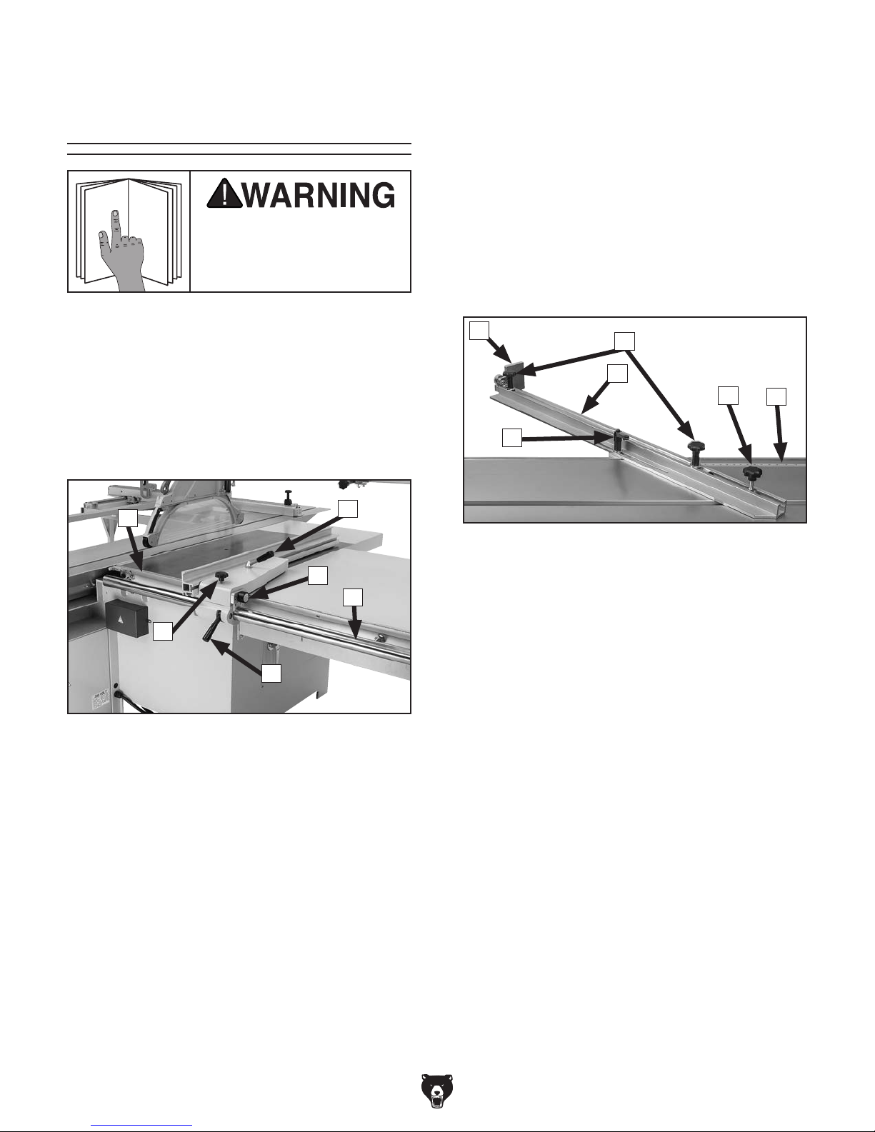
D. Rip Fence Rail. Provides a stable side-
to-side path for sliding rip fence assembly
toward or away from blade.
E. Rip Fence Lock Handle. Secures rip fence
assembly in position along fence rail so
workpiece is stable when cutting.
F. Micro-Adjust Lock Knob. Enables use of
micro-adjust knob for precise positioning of
rip fence.
Miter Fence
Refer to Figures 1–6 and the following descriptions to become familiar with the basic controls
and components of this machine. Understanding
these items and how they work will help you
understand the rest of the manual and stay safe
when operating this saw.
Rip Fence
A
F
E
Figure 1. Rip fence controls.
A. Rip Fence Scale. Helps measure cut during
ripping operations. Features a dual-calibration block to ensure scale is easy to read
whether fence is in high or low position.
B. Slide Lock Handle. Secures aluminum fence
face on its forward/backward slide track.
B
C
D
G
H
Figure 2. Miter fence controls.
G. Flip Stop. Used for quick, precise measure-
ments for repeatable cuts when using miter
fence.
H. Clamp Plate Ratcheting Handle. Locks
miter fence in position once desired angle is
determined.
I. Lock Knobs. Secure position of aluminum
slide bar in miter fence.
J. Pivot Knob. Secures miter fence to sliding
table T-slot.
K. Miter Fence Scale. Helps measure angle of
cut during miter operations. Features resolution of
1
⁄2˚.
I
L
J
K
C. Micro-Adjust Knob. Provides precise adjust-
ment of fence. Loosen micro-adjust lock knob
to use this feature.
-4-
L. Aluminum Slide Bar: Adjusts to extend or
shorten length of miter fence.
Model G0772 (Mfd. Since 05/15)
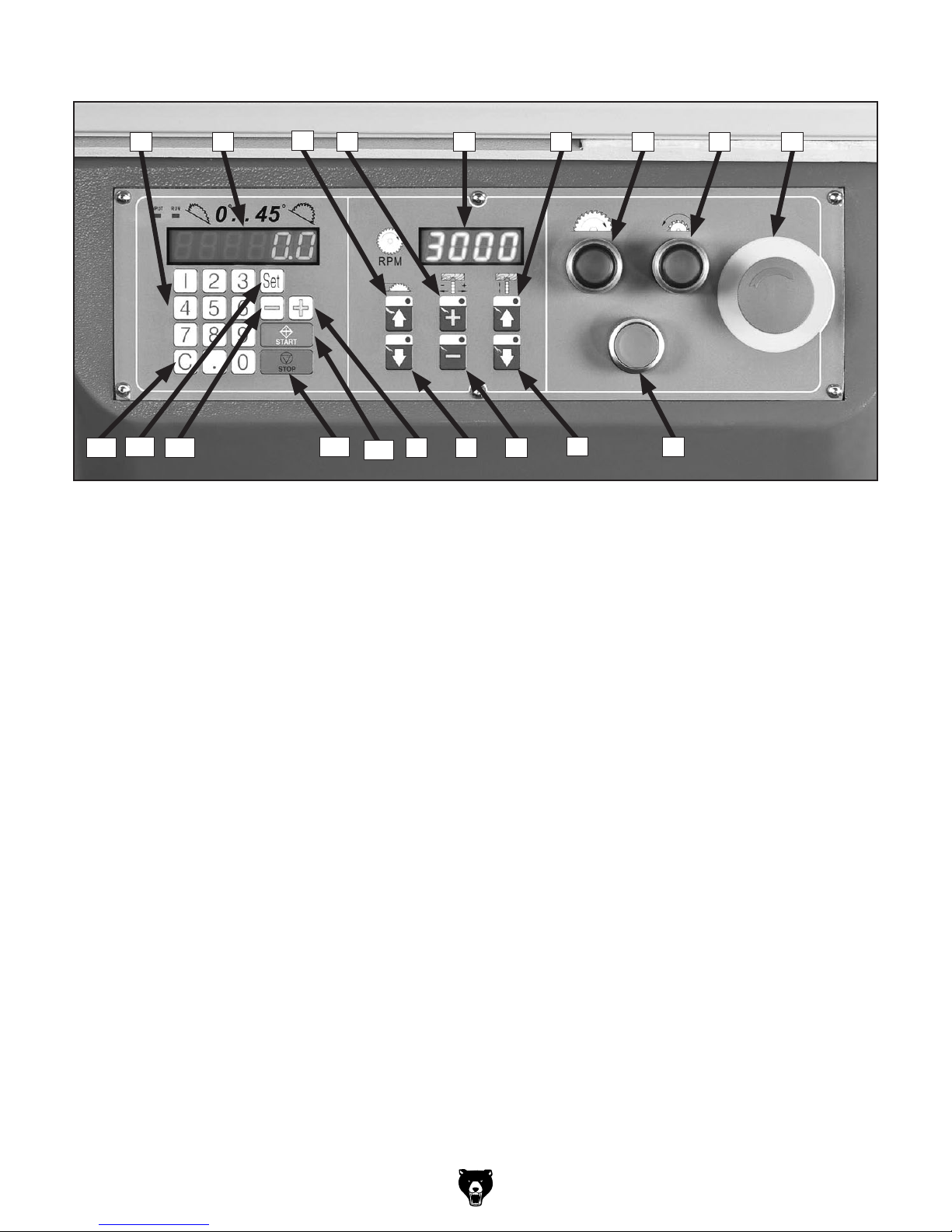
Control Panel
M N
AD
AE
M. Keypad. For entering desired angle of saw
blades.
N. Blade Angle Display. Displays current angle
of saw blades.
O. Main Blade Up Key. Increases height of
main saw blade.
P. Scoring Blade Left Key. Moves scoring
blade left to align with main blade.
Q. Arbor RPM Display. Displays current RPM
of saw blade.
R. Scoring Blade Up Key. Increases height of
scoring blade.
S. Main Blade ON Button. Enables power to
main blade.
T. Scoring Blade ON Button. Enables power
to scoring blade.
U. Emergency Stop Button. Turns both motors
OFF and disables control panel. To reset,
twist clockwise until button pops out.
AC
O
P Q R S T U
AB
AA
Figure 3. Control panel functions.
XYZ
V. Motor OFF Button. Turns both motors OFF.
W. Scoring Blade Down Key. Decreases height
X. Scoring Blade Right Key. Moves scoring
Y. Main Blade Down Key. Decreases height of
Z. "+" Key. Manually increases angle of saw
AA. Start Key. Starts trunnion movement after an
AB. Stop Key. Stops trunnion movement.
AC. "-" Key. Manually decreases angle of saw
AD. Set Key. Sets blade angles entered into key-
AE. "C" Key. Clears typed entries in display.
W
of scoring blade.
blade right to align with main blade.
main saw blade.
blades in increments of 0.1".
angle has been entered.
blades in increments of 0.1".
pad. Also used for calibration.
V
Model G0772 (Mfd. Since 05/15)
-5-
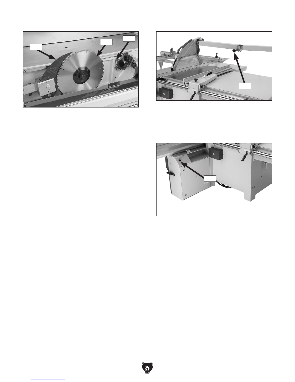
Saw Blades Blade Guard
AG
AF
Figure 4. Saw blades.
AF. Riving Knife. Maintains kerf opening during
cutting operations. This function is crucial to
preventing kickback caused by kerf closing
behind blade.
AG. Main Blade. Performs cutting operation.
AH. Scoring Blade. Rotates in opposite direc-
tion of main blade and pre-cuts surface of
workpiece before actual cutting operation
is performed to reduce tearout or chipping.
Scoring blade is adjustable for kerf thickness
and alignment with main blade.
AH
AI
Figure 5. Blade guard components.
AI. Lock Knob. When loosened, allows blade
guard support arm to swing out of the way.
Master Power
AJ
Figure 6. Location of master power switch.
AJ. Master Power Switch. Enables power flow
to machine.
-6-
Model G0772 (Mfd. Since 05/15)

Glossary Of Terms
The following is a list of common definitions, terms and phrases used throughout this manual as they relate
to this sliding table saw and woodworking in general. Become familiar with these terms for assembling,
adjusting or operating this machine. Your safety is VERY important to us at Grizzly!
Arbor: Metal shaft extending from the drive
mechanism, to which saw blade is mounted.
Bevel Edge Cut: Tilting the arbor and saw blade
to an angle between 0° and 45° to cut a beveled edge onto a workpiece.
Blade Guard: Metal or plastic safety device that
mounts over the saw blade. Its function is to
prevent the operator from coming into contact
with the saw blade.
Crosscut: Cutting operation in which the cross-
cut fence is used to cut across the grain, or
across the shortest width of the workpiece.
Dado Blade: Blade or set of blades that are used
to cut grooves and rabbets.
Dado Cut: Cutting operation that cuts a flat bot-
tomed groove into the face of the workpiece.
Featherboard: Safety device used to keep the
workpiece against the rip fence and against the
table surface.
Kerf: The resulting cut or gap in the workpiece
from the saw blade passing through it while
cutting.
Kickback: A dangerous event that happens if
the blade catches on the workpieces while
cutting. The force of the blade then throws the
workpiece back toward the operator with what
sounds like a horrible explosion. The danger
comes from flying stock striking the operator or
bystanders. The operator’s hands may also be
pulled into the blade during the kickback. Refer
to Preventing Kickback on Page 15 for additional information.
Non-Through Cut: A sawing operation in which
the workpiece is not completely sawn through.
Dado and rabbet cuts are considered NonThrough Cuts because the blade does not
protrude above the top face of the wood stock.
Parallel: When two objects are spaced an equal
distance apart at every point along two given
lines or planes (I.e. the rip fence face is parallel
to the face of the saw blade).
Perpendicular: Lines or planes that intersect and
form right angles. I.e. the blade is perpendicular
to the table surface.
Push Stick: Safety device used to push the
workpiece through a cutting operation. Used
most often when rip cutting thin workpieces.
Rabbet: Cutting operation that creates an
L-shaped channel along the edge of the
workpiece.
Rip Cut: Cutting operation in which the rip fence
is used to cut with the grain, or cut across the
widest width of the workpiece.
Riving Knife: Metal plate located behind the
blade maintains the kerf opening in the wood
when cutting, and helps reduce the risk of injury from a kickback that otherwise would result
in amputation.
Straightedge: A tool with a perfectly straight
edge used to check the flatness, parallelism, or
consistency of a surface(s).
Through Cut: A sawing operation in which the
workpiece is completely sawn through.
Model G0772 (Mfd. Since 05/15)
-7-

SLIDING TABLE
88"
471/4"
SAW CAPACITIES
Customer Service #: (570) 546-9663 • To Order Call: (800) 523-4777 • Fax #: (800) 438-5901
MODEL G0772 14" SLIDING TABLE SAW
126"
126"
61"
Miter Cut 90º
(push cut)
Miter Cut 45º
(push cut)
25"
83"
83"
96"
126"
Cross Cut
Ripping Width
1781/2"
521/2"
Miter Cut 45º
651/4"
451/2"
Miter Cut 45º
(push cut, fence not extended)
-8-
96"
Cross Cut
(fence not extended)
Model G0772 (Mfd. Since 05/15)
126"
66"

MACHINE DATA
SHEET
Customer Service #: (570) 546-9663 · To Order Call: (800) 523-4777 · Fax #: (800) 438-5901
MODEL G0772 14" SLIDING TABLE SAW
Product Dimensions:
Weight............................................................................................................................................................ 2486 lbs.
Width (side-to-side) x Depth (front-to-back) x Height....................................................................... 132 x 130 x 55 in.
Footprint (Length x Width)..................................................................................................................... 64-1/2 x 39 in.
Space Required for Full Range of Movement (Width x Depth)................................................................ 276 x 195 in.
Shipping Dimensions:
Carton #1
Type................................................................................................................................................ Wood Crate
Content................................................................................................................................................. Machine
Weight.................................................................................................................................................. 2389 lbs.
Length x Width x Height............................................................................................................. 90 x 52 x 44 in.
Must Ship Upright......................................................................................................................................... Yes
Carton #2
Type................................................................................................................................................ Wood Crate
Content.......................................................................................................................................... Sliding Table
Weight.................................................................................................................................................... 543 lbs.
Length x Width x Height........................................................................................................... 132 x 19 x 14 in.
Must Ship Upright......................................................................................................................................... Yes
Electrical:
Power Requirement..................................................................................................... 220V or 440V, 3-Phase, 60 Hz
Prewired Voltage.................................................................................................................................................. 220V
Full-Load Current Rating..................................................................................................... 28A at 220V, 14A at 440V
Minimum Circuit Size.......................................................................................................... 40A at 220V, 20A at 440V
Connection Type........................................................................................... Permanent (Hardwire to Shutoff Switch)
Switch Type............................................................................................ Control Panel w/Magnetic Switch Protection
Motors:
Main
Horsepower.............................................................................................................................................. 10 HP
Phase.................................................................................................................................................... 3-Phase
Amps.................................................................................................................................................. 25A/12.5A
Speed................................................................................................................................................ 3450 RPM
Type........................................................................................................................................... TEFC Induction
Power Transfer .................................................................................................................................. Belt Drive
Bearings..................................................................................................... Shielded & Permanently Lubricated
Scoring Blade
Horsepower................................................................................................................................................ 1 HP
Phase.................................................................................................................................................... 3-Phase
Amps...................................................................................................................................................... 3A/1.5A
Speed................................................................................................................................................ 3450 RPM
Type........................................................................................................................................... TEFC Induction
Power Transfer ........................................................................................................................... Flat-Belt Drive
Bearings........................................................................................................... Shielded & Permanently Sealed
Model G0772 (Mfd. Since 05/15)
-9-

Main Specifications:
Operation Information
Main Blade Size......................................................................................................................................... 14 in.
Riving Knife/Spreader Thickness.......................................................................................................... 0.098 in.
Required Blade Body Thickness........................................................................................................... 0.108 in.
Required Blade Kerf Thickness............................................................................................................ 0.108 in.
Main Blade Arbor Size................................................................................................................................. 1 in.
Scoring Blade Size................................................................................................................. 120mm (4-3/4 in.)
Scoring Blade Arbor Size........................................................................................................................ 22 mm
Main Blade Tilt.................................................................................................................................. 0 – 45 deg.
Main Blade Speed............................................................................................... 3000, 4000, 5000, 6000 RPM
Scoring Blade Tilt............................................................................................................................. 0 – 45 deg.
Scoring Blade Speed......................................................................................................................... 8000 RPM
Cutting Capacities
Max Depth of Cut At 90 Deg........................................................................................................................ 4 in.
Max Depth of Cut At 45 Deg.................................................................................................................. 2-3/4 in.
Max Dist From Blade To Column............................................................................................................... 60 in.
Rip Fence Max Cut Width.................................................................................................................... 52-1/2 in.
Sliding Table w/Crosscut Fence Max Cut Width...................................................................................... 126 in.
Sliding Table w/Crosscut Fence Max Cut Length.................................................................................... 126 in.
Miter Fence Max Cut Width at 45 Deg....................................................................................................... 97 in.
Table Information
Floor To Table Height................................................................................................................................ 35 in.
Table Size Length................................................................................................................................ 39-1/4 in.
Table Size Width................................................................................................................................. 34-1/2 in.
Table Size Thickness................................................................................................................................... 3 in.
Table Size With Ext Wings Length............................................................................................................ 60 in.
Table Size With Ext Wings Width........................................................................................................ 59-1/4 in.
Table Size With Ext Wings Thickness......................................................................................................... 3 in.
Sliding Table Length................................................................................................................................ 126 in.
Sliding Table Width.................................................................................................................................... 15 in.
Sliding Table Thickness......................................................................................................................... 8-5/8 in.
Sliding Table T-Slot Top Width................................................................................................................. 7/8 in.
Sliding Table T-Slot Height....................................................................................................................... 3/4 in.
Sliding Table T-Slot Bottom Width............................................................................................................ 7/8 in.
-10 -
Fence Information
Crosscut Fence Type........................................................................... Extruded Aluminum w/Telescoping End
Crosscut Fence Size Length...................................................................................................................... 70 in.
Crosscut Fence Size Max Extended Length..................................................................................... 126-1/2 in.
Crosscut Fence Size Width................................................................................................................... 3-1/4 in.
Crosscut Fence Size Height.................................................................................................................. 2-3/4 in.
Crosscut Fence Number of Stops.................................................................................................................... 2
Rip Fence Type............................................................... 2-Position Single-Lever Locking w/Micro Adjustment
Rip Fence Size Length........................................................................................................................ 47-1/4 in.
Rip Fence Size Width.................................................................................................................................. 2 in.
Rip Fence Size Height........................................................................................................................... 3-5/8 in.
Miter Fence Type............................................................................................. T-Slot Mounted Aluminum Tube
Miter Fence Size Length...................................................................................................................... 47-1/4 in.
Miter Fence Size Max Extended Length.................................................................................................... 83 in.
Miter Fence Size Width......................................................................................................................... 3-1/8 in.
Miter Fence Size Height........................................................................................................................ 1-1/2 in.
Miter Fence Number of Stops........................................................................................................................... 1
Model G0772 (Mfd. Since 05/15)

Construction Materials
Table.................................................................................................................................................... Cast Iron
Sliding Table....................................................................................................................................... Aluminum
Extension Table.......................................................................................................................................... Steel
Cabinet....................................................................................................................................................... Steel
Rip Fence........................................................................................................................................... Aluminum
Miter Fence......................................................................................................................................... Aluminum
Rip Fence Rails.......................................................................................................................... Chromed Steel
Guard....................................................................................................................................................... Plastic
Spindle Bearing Type.................................................................................... Sealed & Permanently Lubricated
Cabinet Paint Type/Finish.................................................................................................................... Urethane
Other Related Information
No of Dust Ports............................................................................................................................................... 2
Dust Port Size.......................................................................................................................................... 3, 5 in.
Other Specifications:
Country of Origin .............................................................................................................................................. Taiwan
Warranty ........................................................................................................................................................... 1 Year
Approximate Assembly & Setup Time ............................................................................................................. 5 Hours
Serial Number Location .................................................................... ID Label on Right Side of Electrical Control Box
ISO 9001 Factory .................................................................................................................................................... No
Certified by a Nationally Recognized Testing Laboratory (NRTL) .......................................................................... No
Features:
Cross-Slide Table with Eccentric Locking Clamp and Hard Chrome-Plated Slideway
Easily Adjustable Saw Guard with Built-In Dust Hood
Miter Fence Adjustable 30 Degrees Left and 45 Degrees Right
Push-Button Digital Control of Blade Speed, Height Adjustments, Blade Tilt, and Scoring Blade Alignment
Scoring Blade Virtually Eliminates Tear-Out
Sliding Table on Vertical Guide System with Precision Bearing Rollers
Accepts 12" and 14" Blades
Model G0772 (Mfd. Since 05/15)
-11-
SECTION 1: SAFETY
For Your Own Safety, Read Instruction
Manual Before Operating This Machine
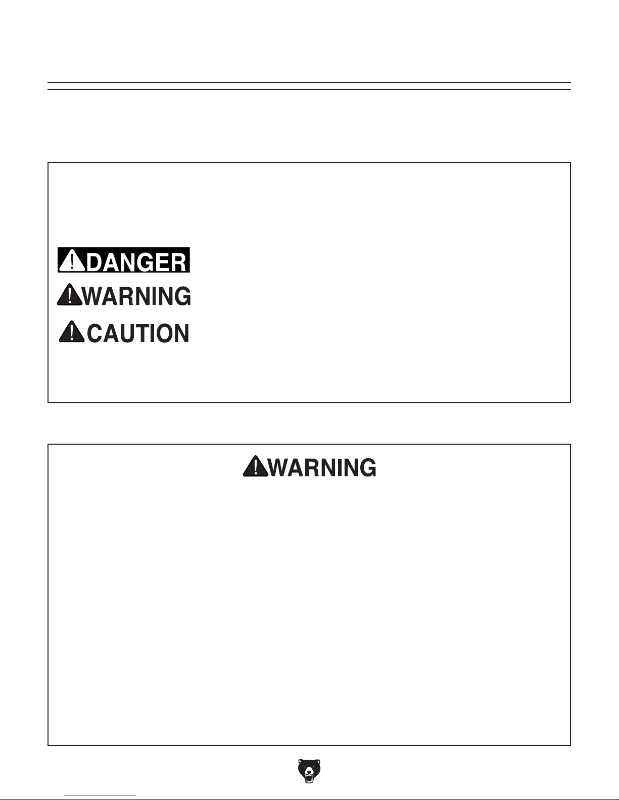
The purpose of safety symbols is to attract your attention to possible hazardous conditions.
This manual uses a series of symbols and signal words intended to convey the level of importance of the safety messages. The progression of symbols is described below. Remember that
safety messages by themselves do not eliminate danger and are not a substitute for proper
accident prevention measures. Always use common sense and good judgment.
Indicates an imminently hazardous situation which, if not avoided,
WILL result in death or serious injury.
Indicates a potentially hazardous situation which, if not avoided,
COULD result in death or serious injury.
Indicates a potentially hazardous situation which, if not avoided,
MAY result in minor or moderate injury. It may also be used to alert
against unsafe practices.
This symbol is used to alert the user to useful information about
NOTICE
proper operation of the machine.
Safety Instructions for Machinery
OWNER’S MANUAL. Read and understand this
owner’s manual BEFORE using machine.
TRAINED OPERATORS ONLY. Untrained operators have a higher risk of being hurt or killed.
Only allow trained/supervised people to use this
machine. When machine is not being used, disconnect power, remove switch keys, or lock-out
machine to prevent unauthorized use—especially
around children. Make your workshop kid proof!
DANGEROUS ENVIRONMENTS. Do not use
machinery in areas that are wet, cluttered, or have
poor lighting. Operating machinery in these areas
greatly increases the risk of accidents and injury.
MENTAL ALERTNESS REQUIRED. Full mental
alertness is required for safe operation of machinery. Never operate under the influence of drugs or
alcohol, when tired, or when distracted.
ELECTRICAL EQUIPMENT INJURY RISKS. You
can be shocked, burned, or killed by touching live
electrical components or improperly grounded
machinery. To reduce this risk, only allow qualified
service personnel to do electrical installation or
repair work, and always disconnect power before
accessing or exposing electrical equipment.
DISCONNECT POWER FIRST.
nect machine from power supply BEFORE making
adjustments, changing tooling, or servicing machine.
This prevents an injury risk from unintended startup
or contact with live electrical components.
EYE PROTECTION. Always wear ANSI-approved
safety glasses or a face shield when operating or
observing machinery to reduce the risk of eye
injury or blindness from flying particles. Everyday
eyeglasses are NOT approved safety glasses.
Always discon-
-12-
Model G0772 (Mfd. Since 05/15)

WEARING PROPER APPAREL. Do not wear
clothing, apparel or jewelry that can become
entangled in moving parts. Always tie back or
cover long hair. Wear non-slip footwear to reduce
risk of slipping and losing control or accidentally
contacting cutting tool or moving parts.
HAZARDOUS DUST. Dust created by machinery
operations may cause cancer, birth defects, or
long-term respiratory damage. Be aware of dust
hazards associated with each workpiece material. Always wear a NIOSH-approved respirator to
reduce your risk.
HEARING PROTECTION. Always wear hearing protection when operating or observing loud
machinery. Extended exposure to this noise
without hearing protection can cause permanent
hearing loss.
REMOVE ADJUSTING TOOLS. Tools left on
machinery can become dangerous projectiles
upon startup. Never leave chuck keys, wrenches,
or any other tools on machine. Always verify
removal before starting!
USE CORRECT TOOL FOR THE JOB. Only use
this tool for its intended purpose—do not force
it or an attachment to do a job for which it was
not designed. Never make unapproved modifications—modifying tool or using it differently than
intended may result in malfunction or mechanical
failure that can lead to personal injury or death!
AWKWARD POSITIONS. Keep proper footing
and balance at all times when operating machine.
Do not overreach! Avoid awkward hand positions
that make workpiece control difficult or increase
the risk of accidental injury.
CHILDREN & BYSTANDERS. Keep children and
bystanders at a safe distance from the work area.
Stop using machine if they become a distraction.
GUARDS & COVERS. Guards and covers reduce
accidental contact with moving parts or flying
debris. Make sure they are properly installed,
undamaged, and working correctly BEFORE
operating machine.
FORCING MACHINERY. Do not force machine.
It will do the job safer and better at the rate for
which it was designed.
NEVER STAND ON MACHINE. Serious injury
may occur if machine is tipped or if the cutting
tool is unintentionally contacted.
STABLE MACHINE. Unexpected movement during operation greatly increases risk of injury or
loss of control. Before starting, verify machine is
stable and mobile base (if used) is locked.
USE RECOMMENDED ACCESSORIES. Consult
this owner’s manual or the manufacturer for recommended accessories. Using improper accessories will increase the risk of serious injury.
UNATTENDED OPERATION. To reduce the
risk of accidental injury, turn machine OFF and
ensure all moving parts completely stop before
walking away. Never leave machine running
while unattended.
MAINTAIN WITH CARE. Follow all maintenance
instructions and lubrication schedules to keep
machine in good working condition. A machine
that is improperly maintained could malfunction,
leading to serious personal injury or death.
DAMAGED PARTS. Regularly inspect machine
for damaged, loose, or mis-adjusted parts—or
any condition that could affect safe operation.
Immediately repair/replace BEFORE operating
machine. For your own safety, DO NOT operate
machine with damaged parts!
MAINTAIN POWER CORDS. When disconnecting cord-connected machines from power, grab
and pull the plug—NOT the cord. Pulling the cord
may damage the wires inside. Do not handle
cord/plug with wet hands. Avoid cord damage by
keeping it away from heated surfaces, high traffic
areas, harsh chemicals, and wet/damp locations.
EXPERIENCING DIFFICULTIES. If at any time
you experience difficulties performing the intended operation, stop using the machine! Contact our
Technical Support at (570) 546-9663.
Model G0772 (Mfd. Since 05/15)
-13-

Additional Safety for Sliding Table Saws
Serious injury or death can occur from getting cut or having body parts, such as fingers,
amputated by rotating saw blade. Workpieces thrown by kickback can strike operators or
bystanders with deadly force. Flying particles from cutting operations or broken blades can
cause eye injuries or blindness. To minimize risk of getting hurt or killed, anyone operating
machine MUST completely heed hazards and warnings below.
HAND & BODY POSITIONING. Keep hands
away from saw blade and out of blade path during operation, so they cannot slip accidentally into
blade. Stand to side of blade path. Never reach
around, behind, or over blade. Only operate at
front of machine.
BLADE GUARD. Use blade guard for all cuts
that allow it to be used safely. Make sure blade
guard is installed and adjusted correctly. Promptly
repair or replace if damaged. Re-install blade
guard immediately after operations that require its
removal.
RIVING KNIFE. Use riving knife for all cuts. Make
sure riving knife is aligned and positioned correctly. Promptly repair or replace it if damaged.
KICKBACK. Kickback occurs when saw blade
ejects workpiece back toward operator. Know how
to reduce risk of kickback. Learn how to protect
yourself if it does occur.
FENCE ADJUSTMENTS. Make sure rip fence
remains properly adjusted and parallel with blade.
Always lock fence before using.
PUSH STICKS/BLOCKS. Use push sticks or
push blocks whenever possible to keep your
hands farther away from blade while cutting. In
event of an accident these devices will often take
damage that would have happened to hands/
fingers.
BLADE ADJUSTMENTS. Adjusting blade height
or tilt during operation increases risk of crashing blade and sending metal fragments flying
with deadly force at operator or bystanders. Only
adjust blade height and tilt when blade is completely stopped and saw is OFF.
CHANGING BLADES. Always disconnect power
before changing blades. Changing blades while
saw is connected to power greatly increases
injury risk if saw is accidentally powered up.
WORKPIECE CONTROL. Feeding workpiece
incorrectly increases risk of kickback. Make sure
workpiece is in stable position on tables and
supported by rip fence or crosscut fence during
cutting operation. Never start saw with workpiece
touching blade. Allow blade to reach full speed
before cutting. Only feed workpiece against direction of main blade rotation. Always use some type
of guide to feed workpiece in a straight line. Never
back workpiece out of cut or move it backwards
or sideways after starting a cut. Feed cuts all the
way through to completion. Never perform any
operation “freehand”. Turn OFF saw and wait
until blade is completely stopped before removing
workpiece.
-14-
DAMAGED SAW BLADES. Never use blades
that have been dropped or otherwise damaged.
CUTTING CORRECT MATERIAL. Never cut
materials not intended for this saw. Only cut natural and man-made wood products, laminate covered wood products, and some plastics. Cutting
metal, glass, stone, tile, etc. increases risk of
operator injury due to kickback or flying particles.
Model G0772 (Mfd. Since 05/15)

Preventing Kickback
Protecting Yourself
Do the following to prevent kickback:
• When rip cutting, only cut workpieces that
have at least one smooth and straight edge.
DO NOT cut excessively warped, cupped or
twisted wood. If workpiece warpage is questionable, always choose another workpiece.
• Never attempt freehand cuts. If the workpiece
is not fed parallel with the blade, kickback
will likely occur. Always use the rip fence or
crosscut fence to support the workpiece.
• Ensure sliding table slides parallel with the
blade; otherwise, the chances of kickback are
extreme. Take the time to check and adjust
the sliding table before cutting.
• Always use the riving knife whenever possible. It reduces risk of kickback and reduces
your risk of injury if it does occur.
• Always keep blade guard installed and in
good working order.
• Feed cuts through to completion. Any time
you stop feeding a workpiece in the middle
of a cut, the chance of kickback is greatly
increased.
From Kickback
Even if you know how to prevent kickback, it
may still happen. Here are some precautions
to help protect yourself if kickback DOES
occur:
• Stand to the side of the blade path when
cutting. If a kickback does occur, the thrown
workpiece usually travels directly towards the
front of the blade.
• Wear safety glasses or a face shield. In the
event of a kickback, your eyes and face are
the most vulnerable parts of your body.
• Never, for any reason, place your hand behind
the blade path. Should kickback occur, your
hand will be pulled into the blade.
• Use a push stick or push block to keep your
hands farther away from the moving blade. If
a kickback occurs, these safety devices will
most likely take the damage that your hand
would have received.
• Use featherboards or anti-kickback devices
to prevent or slow down kickback.
• Ensure rip fence is adjusted parallel with the
blade; otherwise, the chances of kickback are
extreme. Take the time to check and adjust
the rip fence before cutting.
Statistics show that the most common accidents among table saw users can be linked
to kickback. Kickback is typically defined as
the high-speed expulsion of stock from the
table saw toward the operator. In addition to
the danger of the operator or others in the
area being struck by the flying stock, it is
often the case that the operator’s hands are
pulled into the blade during the kickback.
Model G0772 (Mfd. Since 05/15)
-15-

SECTION 2: POWER SUPPLY
Before installing the machine, consider the availability and proximity of the required power supply
circuit. If an existing circuit does not meet the
requirements for this machine, a new circuit must
be installed. To minimize the risk of electrocution,
fire, or equipment damage, installation work and
electrical wiring must be done by an electrician or
qualified service personnel in accordance with all
applicable codes and standards.
or equipment damage
may occur if machine is
not properly grounded
and connected to power
The full-load current rating is the amperage a
machine draws at 100% of the rated output power.
On machines with multiple motors, this is the
amperage drawn by the largest motor or sum of all
motors and electrical devices that might operate
at one time during normal operations.
The full-load current is not the maximum amount
of amps that the machine will draw. If the machine
is overloaded, it will draw additional amps beyond
the full-load rating.
If the machine is overloaded for a sufficient length
of time, damage, overheating, or fire may result—
especially if connected to an undersized circuit.
To reduce the risk of these hazards, avoid overloading the machine during operation and make
sure it is connected to a power supply circuit that
meets the specified circuit requirements.
This machine is prewired to operate on a power
supply circuit that has a verified ground and meets
the following requirements:
This machine can be converted to operate on a
power supply circuit that has a verified ground
and meets the requirements listed below. (Refer
to Voltage Conversion instructions for details.)
Note: Circuit requirements in this manual apply to
a dedicated circuit—where only one machine will
be running on the circuit at a time. If machine will
be connected to a shared circuit where multiple
machines may be running at the same time, consult an electrician or qualified service personnel to
ensure circuit is properly sized for safe operation.
For your own safety and protection of
A power supply circuit includes all electrical
equipment between the breaker box or fuse panel
in the building and the machine. The power supply circuit used for this machine must be sized to
safely handle the full-load current drawn from the
machine for an extended period of time. (If this
machine is connected to a circuit protected by
fuses, use a time delay fuse marked D.)
Availability
Electrocution, fire, shock,
supply.
Full-Load Current Rating
Circuit Information
property, consult an electrician if you are
unsure about wiring practices or electrical
codes in your area.
Full-Load Current Rating at 220V ..... 28 Amps
Full-Load Current Rating at 440V ..... 14 Amps
-16 -
Circuit Requirements for 220V
Nominal Voltage ................... 220V, 230V, 240V
Cycle .......................................................... 60 Hz
Phase .................................................... 3-Phase
Power Supply Circuit ......................... 40 Amps
Circuit Requirements for 440V
Nominal Voltage ............................. 440V, 480V
Cycle .......................................................... 60 Hz
Phase .................................................... 3-Phase
Power Supply Circuit ......................... 20 Amps
Model G0772 (Mfd. Since 05/15)
Since this machine must be permanently connected to the power supply, an extension cord
cannot be used.
Connection Type Phase Converters
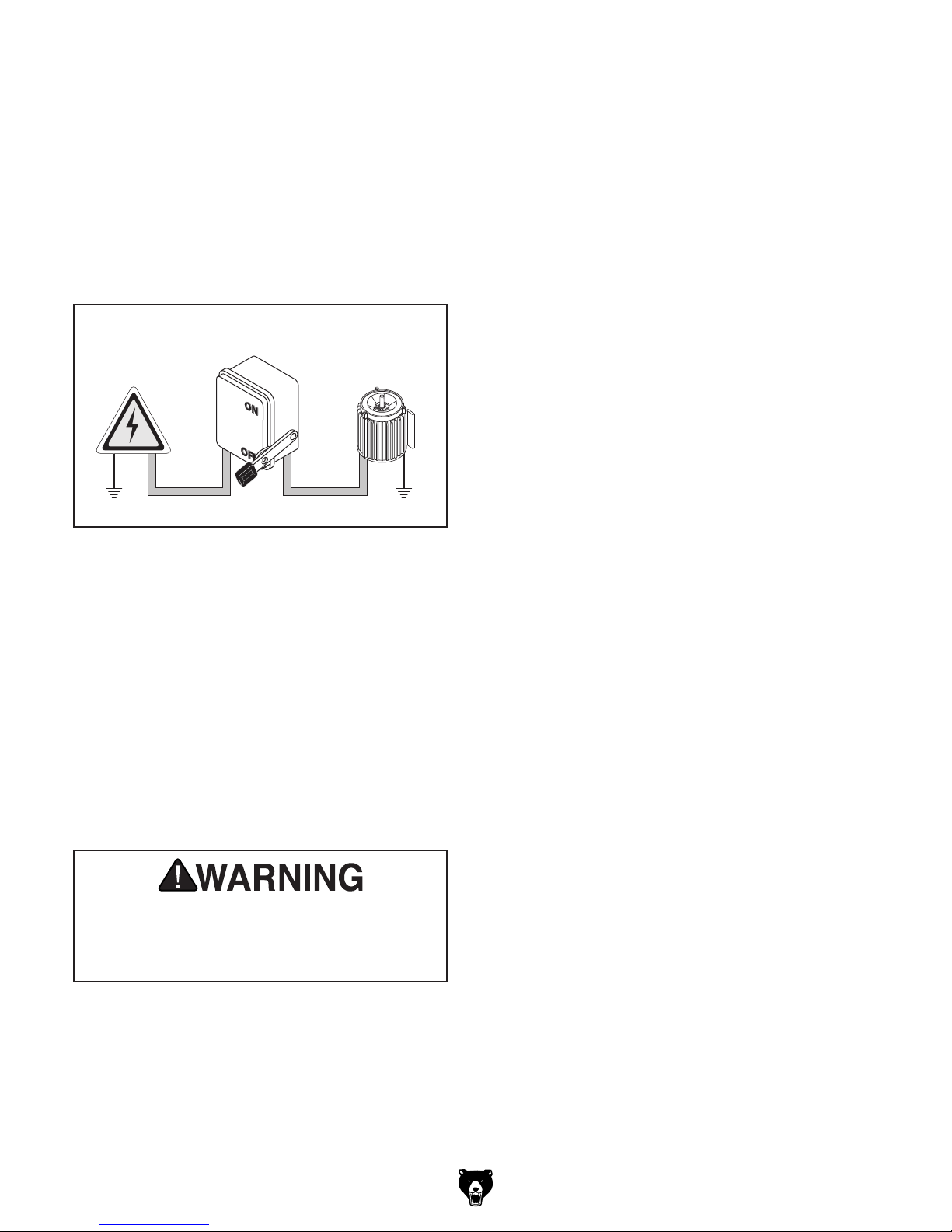
A permanently connected (hardwired) power supply is typically installed with wires running through
mounted and secured conduit. A disconnecting
means, such as a locking switch (see following
figure), must be provided to allow the machine
to be disconnected (isolated) from the power
supply when required. This installation must be
performed by an electrician in accordance with all
applicable electrical codes and ordinances.
In the event of a malfunction or breakdown,
grounding provides a path of least resistance
for electrical current to reduce the risk of electric
shock. A permanently connected machine must
be connected to a grounded metal permanent wiring system; or to a system having an equipmentgrounding conductor. All grounds must be verified
and rated for the electrical requirements of the
machine. Improper grounding can increase the
risk of electric shock!
Avoid using a static phase converter to supply
3-Phase power for this machine, as it could
damage or decrease the life of sensitive electrical
components. If you must use a phase converter,
only use a rotary phase converter that is sized
at least 50% larger than the largest HP rating of
this machine. If using a phase converter to supply
power, only connect the manufactured leg or "wild
wire" to the "S" terminal (see location on Page
87). The S terminal can handle power fluctuations
because it is wired directly to the motor.
Locking
Power
Source
Disconnect Switch
Machine
ConduitConduit
Ground
Figure 7. Typical setup of a permanently
connected machine.
Ground
Grounding Instructions
Serious injury could occur if you connect
machine to power before completing setup
process. DO NOT connect to power until
instructed later in this manual.
Extension Cords
Model G0772 (Mfd. Since 05/15)
-17-
440V Conversion
The Model G0772 can be converted for 440V
operation using the optional Part# P07721412.
This can be purchased by contacting the Grizzly
Order Desk at (800) 523-4777. This conversion
job consists of: 1) replacing the overload relays, 2)
rewiring the transformer for 440V operation, and
3) rewiring the main and scoring blade motors for
440V operation.
All wiring changes must be done by an electrician
or qualified service personnel before the saw is
connected to the power source. If, at any time
during this procedure you need help, call Grizzly
Tech Support at (570) 546-9663.
Before performing the conversion procedure, we
recommend setting the blade to 0° and raising it
all the way up to create clearance under the main
and scoring motor junction boxes for rewiring.
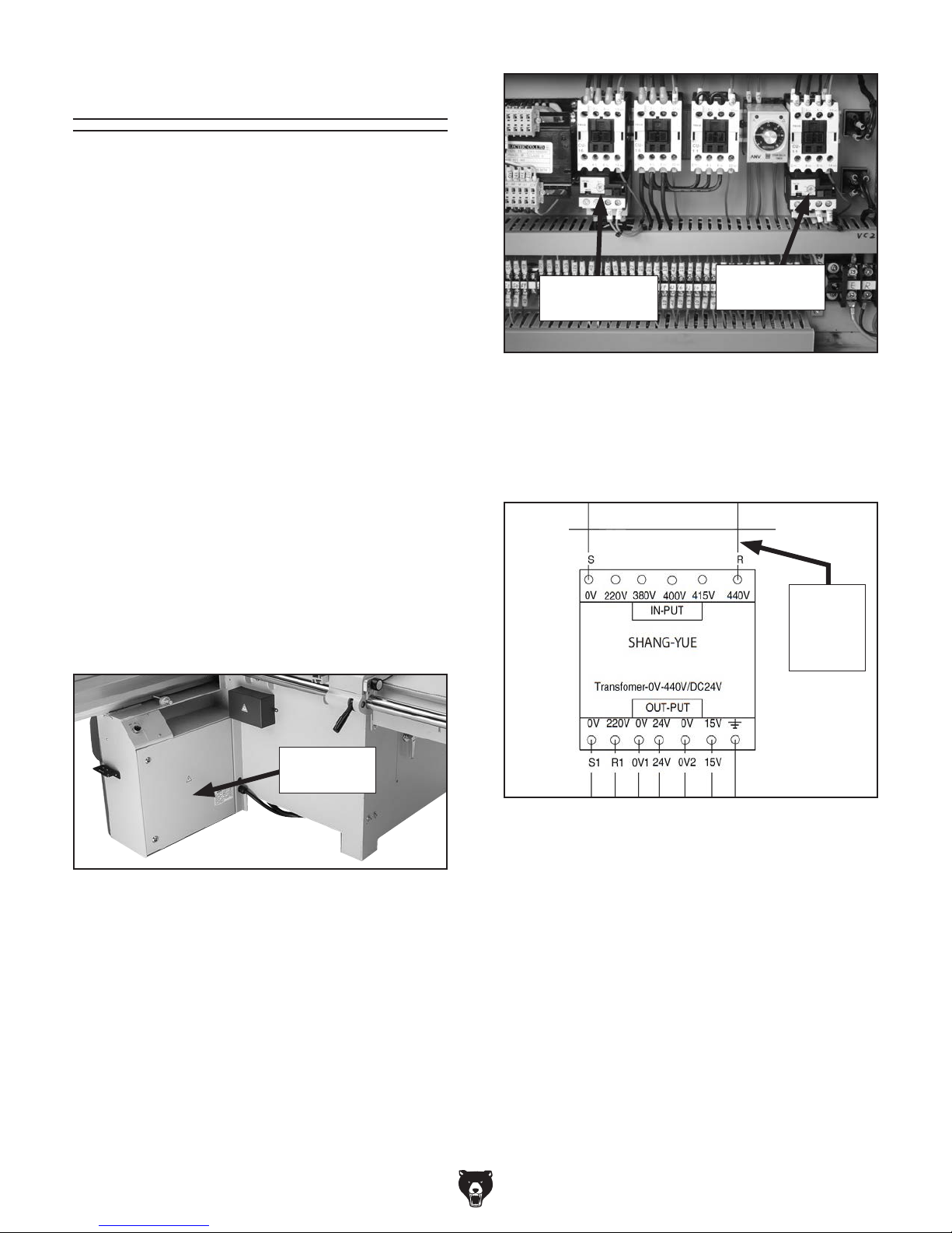
RHU-10/7.5K1
(Set to 6.5A)
Figure 9. Overload relays from 440V Conversion
Kit installed and set for specified trip current.
5. At voltage transformer, more the R wire from
the 220V terminal to the 440V terminal (see
Figure 10).
RHU-10/2K1
(Set to 1.6A)
To convert G0772 for 440V operation:
1. DISCONNECT MACHINE FROM POWER!
2. Open electrical panel door (see Figure 8).
Electrical
Panel Door
Figure 8. Location of electrical panel door.
3. Remove main motor overload relay for 220V.
Replace with RHU-10/7.5K1 overload relay
included with 440V Conversion Kit. Set overload dial to 6.5A (see Figure 9).
"R" Wire
Moved
to 440V
Terminal
Figure 10. R wire moved to 440V terminal on
transformer.
6. Close electrical panel door.
7. Open motor cabinet door on back of saw.
8. Rewire main blade and scoring blade motors
to 440V. Refer to wiring diagrams on Pages
93–92.
4. Remove scoring motor overload relay for
220V. Replace with RHU-10/2K1 overload
relay included with 440V Conversion Kit. Set
amperage dial to 1.6A (see Figure 9).
-18-
9. Close motor cabinet door.
Model G0772 (Mfd. Since 05/15)
SECTION 3: SETUP
This machine was carefully packaged for safe
transport. When unpacking, separate all enclosed
items from packaging materials and inspect them
for shipping damage.
,
please
IMPORTANT:
you are completely satisfied with the machine and
have resolved any issues between Grizzly or the
shipping agent. You MUST have the original pack-
aging to file a freight claim. It is also extremely
helpful if you need to return your machine later.
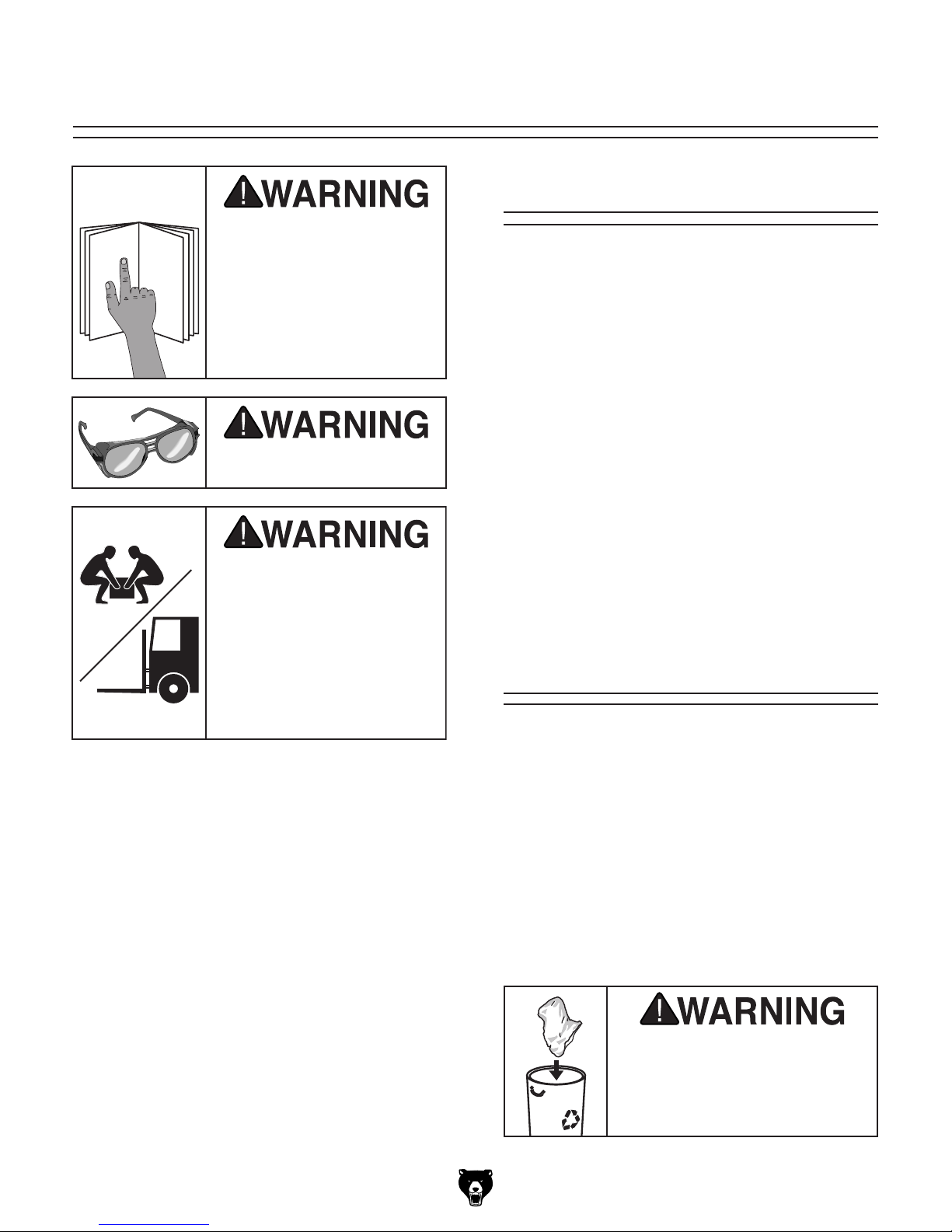
Keep children and pets away
from plastic bags or packing
materials shipped with this
Needed for Setup
This machine presents
serious injury hazards
to untrained users. Read
through this entire manual to become familiar with
the controls and operations before starting the
machine!
Wear safety glasses during
the entire setup process!
HEAVY LIF T!
Straining or crushing injury
may occur from improperly
lifting machine or some of
its parts. To reduce this risk,
get help from other people
and use a forklift (or other
lifting equipment) rated for
weight of this machine.
The following items are needed, but not included,
for the setup/assembly of this machine.
Description Qty
• Additional People ....................................... 4
• Safety Glasses ........................ 1 Per Person
• Cleaner/Degreaser (Page 23) .... As Needed
• Disposable Shop Rags ............... As Needed
• Forklift (Rated for at least 3000 lbs.) .......... 1
• Straightedge 4' ........................................... 1
• Level ........................................................... 1
• Screwdriver Phillips #2 ............................... 1
• Open-End Wrenches 13mm, 19mm ......1 Ea
• Dust Collection System w/5" Branch Line . . 1
• Dust Hose & Hose Clamp 5" .................1 Ea
• Dust Hose & Hose Clamp 3" .................1 Ea
• Y-Fitting 3" x 5" x 5".................................... 1
• Feeler Gauge Set ....................................... 1
Unpacking
Model G0772 (Mfd. Since 05/15)
If items are damaged
call us immediately at (570) 546-9663.
Save all packaging materials until
SUFFOCATION HAZARD!
machine. Discard immediately.
-19 -

5mm
Hardware Recognition Chart
-20-
Model G0772 (Mfd. Since 05/15)
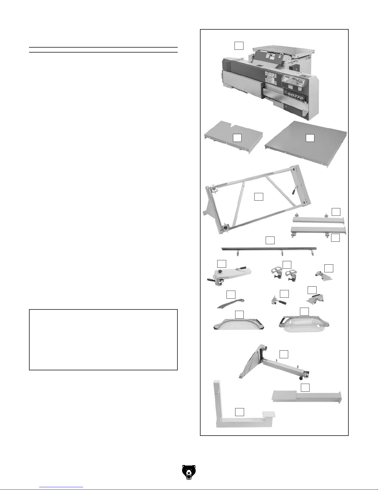
Inventory
The following is a list of items shipped with your
machine. Before beginning setup, lay these items
out and inventory them.
If any non-proprietary parts are missing (e.g. a
nut or a washer), we will gladly replace them; or
for the sake of expediency, replacements can be
obtained at your local hardware store.
A
Crate 1 (Figure 11) Qty
A. Saw Base Unit ............................................ 1
B. Small Extension Table ................................ 1
C. Large Extension Table ............................... 1
D. Crosscut Table Frame ................................ 1
E. Large Extension Table Brace (L) ................ 1
F. Large Extension Table Brace (R) ............... 1
G. Rip Fence Rail w/Fasteners ....................... 1
—Hex Nuts M20-2.5................................... 9
—Flat Washers 20mm ............................... 6
H. Rip Fence Base Assembly ......................... 1
I. Crosscut Fence Flip Stops ......................... 2
J. End Plate (Sliding Table) ............................ 1
K. End Handle (Sliding Table) ......................... 1
L. Push Handle ............................................... 1
M. Push Stick .................................................. 1
N. Flat Blade Guard Assembly ....................... 1
O. Bubble Blade Guard Assembly .................. 1
P. Blade Guard Swing Arm ............................. 1
Q. Blade Guard Lower Support Arm ............... 1
R. Blade Guard Upper Support Arm ............... 1
NOTICE
If you cannot find an item on this list, carefully check around/inside the machine and
packaging materials. Often, these items get
lost in packaging materials while unpacking or they are pre-installed at the factory.
B
D
G
H
M
N
I
L
P
C
E
F
J
K
O
Model G0772 (Mfd. Since 05/15)
Q
R
Figure 11. Crate 1 inventory.
-21-
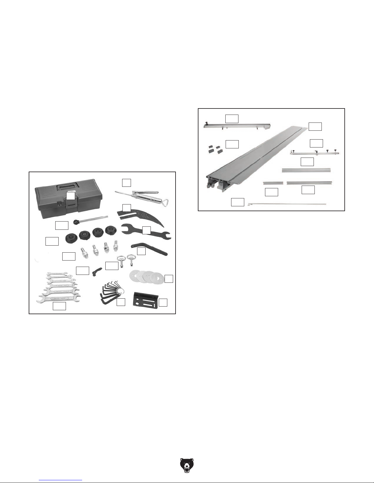
Crate 1 Continued (Figure 12) Qty
S. To ol B ox...................................................... 1
T. Grease Gun ................................................ 1
U. Riving Knife ................................................ 1
V. Open-End Wrench 30 x 41mm ................... 1
W. Scoring Blade Wrench ............................... 1
X. Scoring Blade Shims .................................. 4
Y. Tool Holder ................................................. 1
Z. Hex Wrench Set
(1.5, 2, 2.5, 3, 4, 5, 5.5, 6, 8, 10mm) ...1 Ea
AA. Open-End Wrench Set ............ (8/10, 10/12,
11/13, 14/17, 17/19, 22/24mm) .............1 Ea
AB. Blade Locking Tool ..................................... 1
AC. Base Feet ................................................... 4
AD. Hex Bolts M16-2 x 70 w/Hex Nuts.............. 4
AE. Sliding Table Lever ..................................... 1
AF. Cabinet Keys .............................................. 2
T
S
U
AB
V
AC
W
AD
AF
AE
X
AA
Z
Y
Crate 2 (Figure 13) Qty
AI. Crosscut Fence .......................................... 1
AJ. Sliding Table ............................................... 1
AK. Miter Fence ................................................ 1
AL. Rip Fence ................................................... 1
AM. Short Support Bar ...................................... 1
AN. Long Support Bar ....................................... 1
AO. Rip Fence Table Scale Bracket ................. 1
AP. End-Caps ................................................... 4
AI
AJ
AP
AK
AL
AM
AN
AO
Figure 13. Crate 2 inventory.
Hardware (not shown) Qty
Blade Guard Lower Support Arm:
—Hex Bolts M10-1.5 x 25 ........................... 4
—Lock Washers 10mm .............................. 4
—Flat Washers 10mm ................................ 4
Blade Guard Upper Support Arm:
—Hex Bolts M10-1.5 x 25 ........................... 2
—Lock Washers 10mm .............................. 2
—Flat Washers 10mm ................................ 2
Figure 12. Crate 1 toolbox inventory.
-22-
Crosscut Fence:
— Wood End-Cap ...................................... 1
— Tap Screws #6 x 1" ................................ 4
— Flat Washers 4mm ................................. 4
Rip Fence Table Scale Bracket:
—Flat Hd. Screws M6-1 x 30 ..................... 2
—Flat Hd. Screws M6-1 x 35 ..................... 2
—Flat Washers 6mm ................................. 2
—Lock Washers 6mm ................................ 2
—Hex Nuts M6-1 ....................................... 2
Sliding Table:
— Cap Screw M14-2 x 45 ........................... 4
— Flat Washer 14mm .................................. 4
— Lock Washer 14mm ................................ 4
Model G0772 (Mfd. Since 05/15)
The unpainted surfaces of your machine are
coated with a heavy-duty rust preventative that
prevents corrosion during shipment and storage.
This rust preventative works extremely well, but it
will take a little time to clean.
Be patient and do a thorough job cleaning your
machine. The time you spend doing this now will
give you a better appreciation for the proper care
of your machine's unpainted surfaces.
There are many ways to remove this rust preventative, but the following steps work well in a wide
variety of situations. Always follow the manufacturer’s instructions with any cleaning product you
use and make sure you work in a well-ventilated
area to minimize exposure to toxic fumes.
Before cleaning, gather the following:
• Disposable rags
• Cleaner/degreaser (WD•40 works well)
• Safety glasses & disposable gloves
• Plastic paint scraper (optional)
Basic steps for removing rust preventative:
1.
2.
3.
4.
Many cleaning solvents
work in a well-ventilated
Avoid chlorine-based solvents, such as
Cleanup
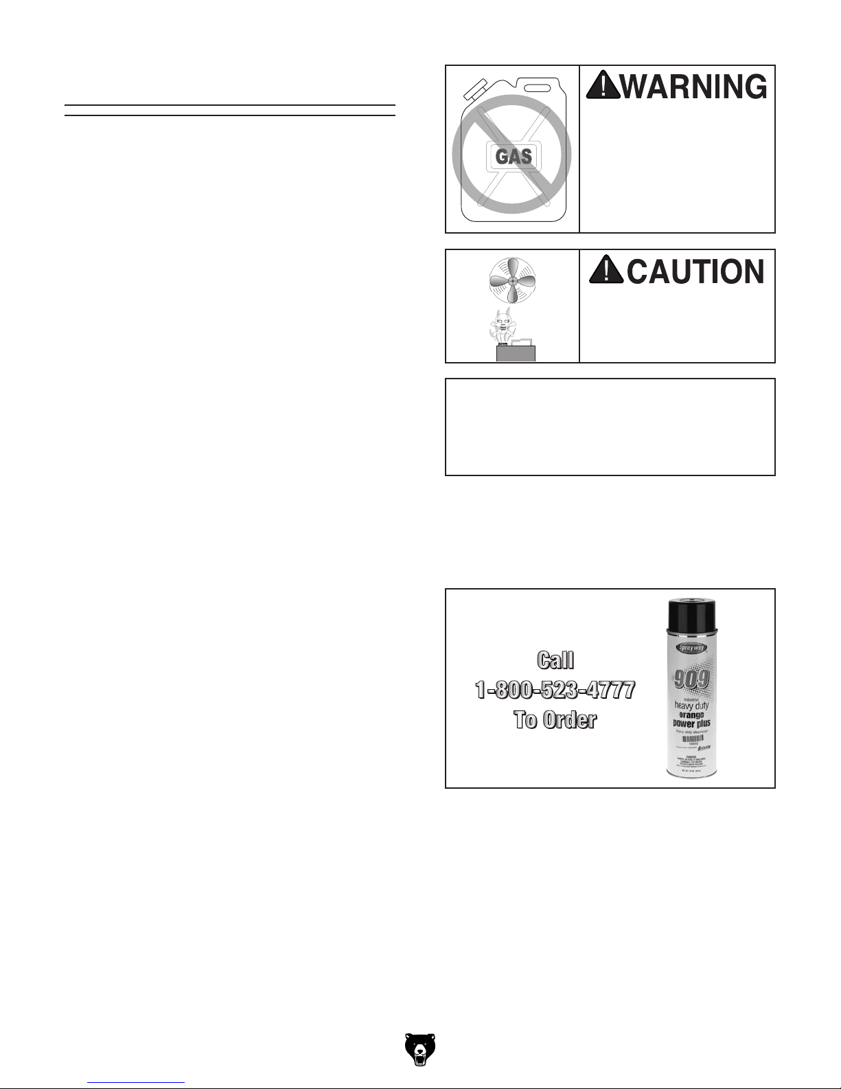
Gasoline and petroleum
products have low flash
points and can explode
or cause fire if used to
clean machinery. Avo id
using these products
to clean machinery.
Put on safety glasses.
Coat the rust preventative with a liberal
amount of cleaner/degreaser, then let it soak
for 5–10 minutes.
Wipe off the surfaces. If your cleaner/degreas-
er is effective, the rust preventative will wipe
off easily. If you have a plastic paint scraper,
scrape off as much as you can first, then wipe
off the rest with the rag.
Repeat Steps 2–3 as necessary until clean,
then coat all unpainted surfaces with a quality
metal protectant to prevent rust.
are toxic if inhaled. Only
area.
NOTICE
acetone or brake parts cleaner, that may
damage painted surfaces.
T23692—Orange Power Degreaser
A great product for removing the waxy shipping grease from the non-painted parts of the
machine during clean up.
Figure 14. T23692 Orange Power Degreaser.
Model G0772 (Mfd. Since 05/15)
-23-
Site Considerations
Weight Load
Refer to the
of your machine. Make sure that the surface upon
which the machine is placed will bear the weight
of the machine, additional equipment that may be
installed on the machine, and the heaviest workpiece that will be used. Additionally, consider the
weight of the operator and any dynamic loading
that may occur when operating the machine.
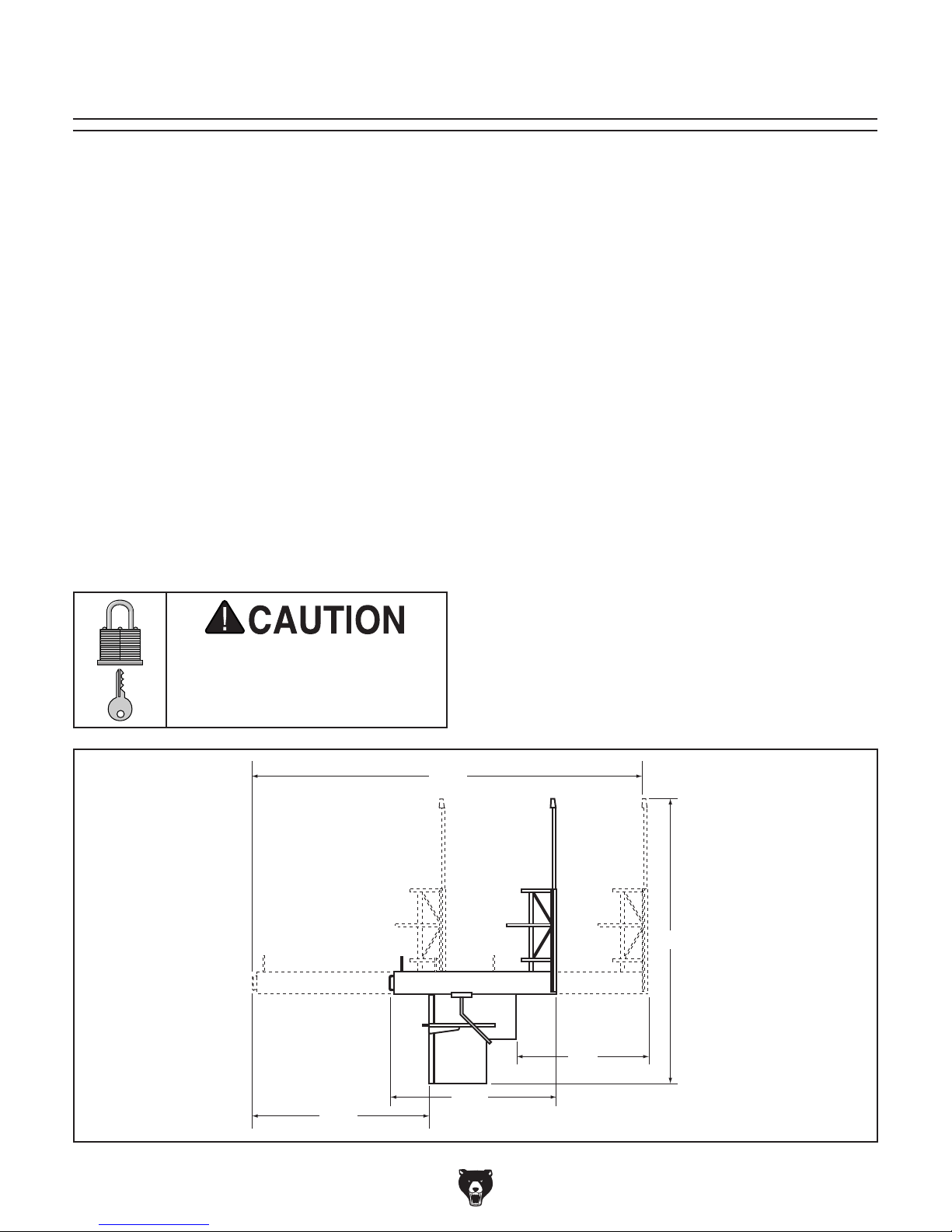
Space Allocation
Consider the largest size of workpiece that will
be processed through this machine and provide
enough space around the machine for adequate
operator material handling or the installation of
auxiliary equipment. With permanent installations,
leave enough space around the machine to open
or remove doors/covers as required by the maintenance and service described in this manual.
See below for required space allocation.
Physical Environment
Extreme conditions for this type of machinery are
Place this machine near an existing power source.
other hazards. Make sure to leave enough space
Shadows, glare, or strobe effects that may distract
or impede the operator must be eliminated.
Machine Data Sheet for the weight
Children or untrained people
may be seriously injured by
this machine. Only install in an
access restricted location.
The physical environment where the machine is
operated is important for safe operation and longevity of machine components. For best results,
operate this machine in a dry environment that is
free from excessive moisture, hazardous chemicals, airborne abrasives, or extreme conditions.
generally those where the ambient temperature
range exceeds 41°–104°F; the relative humidity
range exceeds 20%–95% (non-condensing); or
the environment is subject to vibration, shocks,
or bumps.
Electrical Installation
Make sure all power cords are protected from
traffic, material handling, moisture, chemicals, or
around machine to disconnect power supply or
apply a lockout/tagout device, if required.
Lighting
276"
Lighting around the machine must be adequate
enough that operations can be performed safely.
119"
Figure 15. Minimum working clearances.
-24-
195"
130"
88"
Model G0772 (Mfd. Since 05/15)
Lifting & Placing
get help from other people
Saw
HEAVY LIF T!
Straining or crushing injury
may occur from improperly
lifting machine or some of
its parts. To reduce this risk,
and use a forklift (or other
lifting equipment) rated for
weight of this machine.
To lift and place saw:
1. Position crate as close to installation location
as possible.
2. Remove top of crate. Position forklift forks as
wide as they can be while still fitting under
center opening (see Figure 16).
DO NOT lift saw any higher than necessary
to clear pallet. Serious personal injury and
machine damage may occur if safe moving
methods are not followed.
4. With an assistant holding each end to help
stabilize load, lift saw with forklift just high
enough to clear pallet, and move it to your
predetermined location.
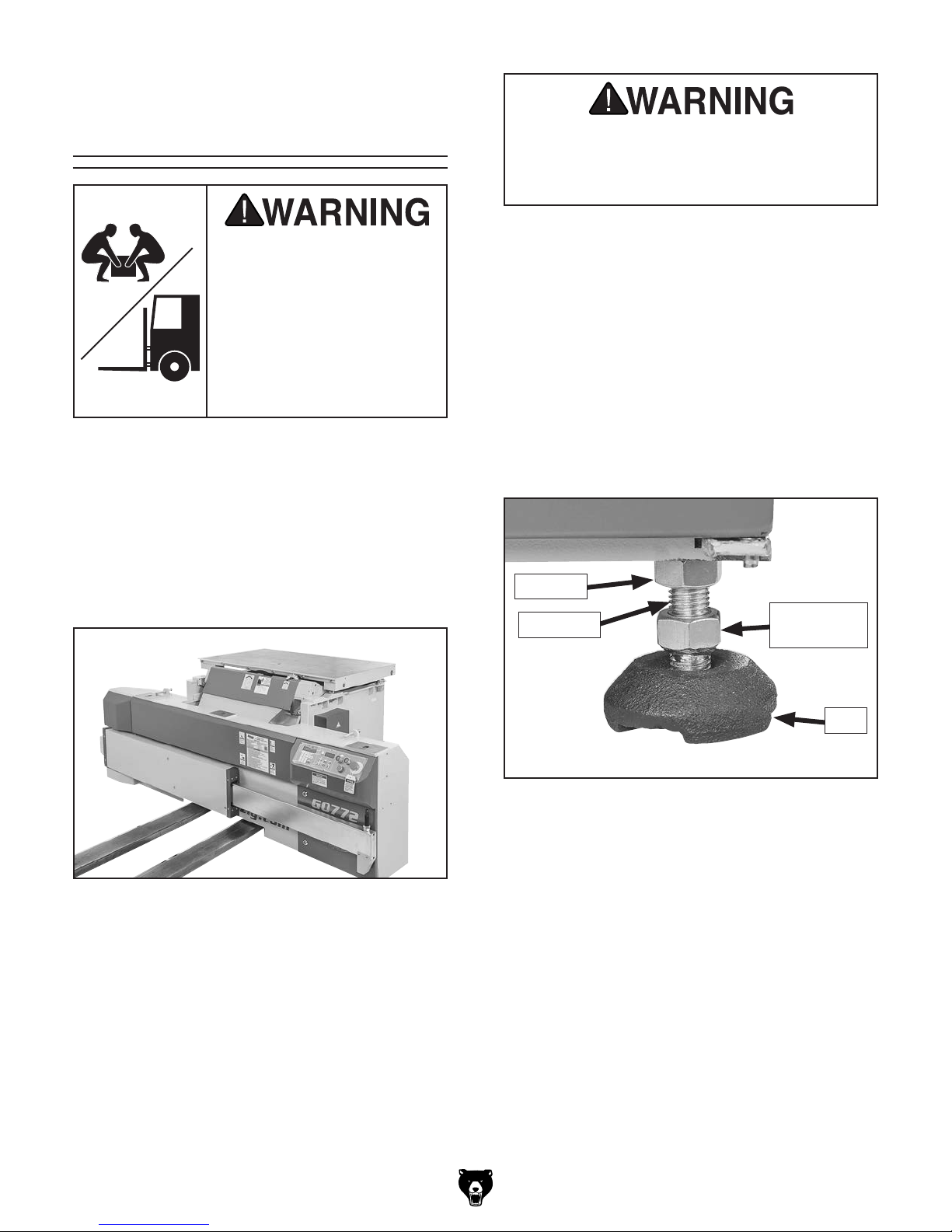
5. Place each foot under one of four mounting
holes in frame, then thread foot stud into
frame roughly half its length (see Figure 17),
making sure jam nuts are installed on studs.
6. Carefully lower studs onto feet with forklift
(see Figure 17), and then back forklift away.
Jam Nut
Foot Stud
Adjustment
Hex Nut
Figure 16. Inserting forks for lifting table saw.
3. Remove small items packed around saw and
unbolt saw from pallet.
Foot
Figure 17. Foot components properly installed in
frame and resting on foot.
7. Place level on cast-iron table. Rotate adjustment hex nut (see Figure 17) at each foot,
to level saw table from left-to-right and from
front-to-back. Leveling saw allows sliding
table to move smoothly.
8. Tighten jam nuts against frame to prevent
feet from moving after leveling.
Model G0772 (Mfd. Since 05/15)
-25-
Assembly
It takes approximately two hours to assemble the
saw and make the required adjustments to prepare the saw for the test run.
The sliding table weighs approximately 330 lbs.
and is shipped upside down in the crate. It must
be lifted and carefully positioned right-side up
onto the saw frame during assembly. If you are
using a forklift, you'll need to use cardboard or
heavy cloth between table and forklift to prevent
scratching the aluminum surface.
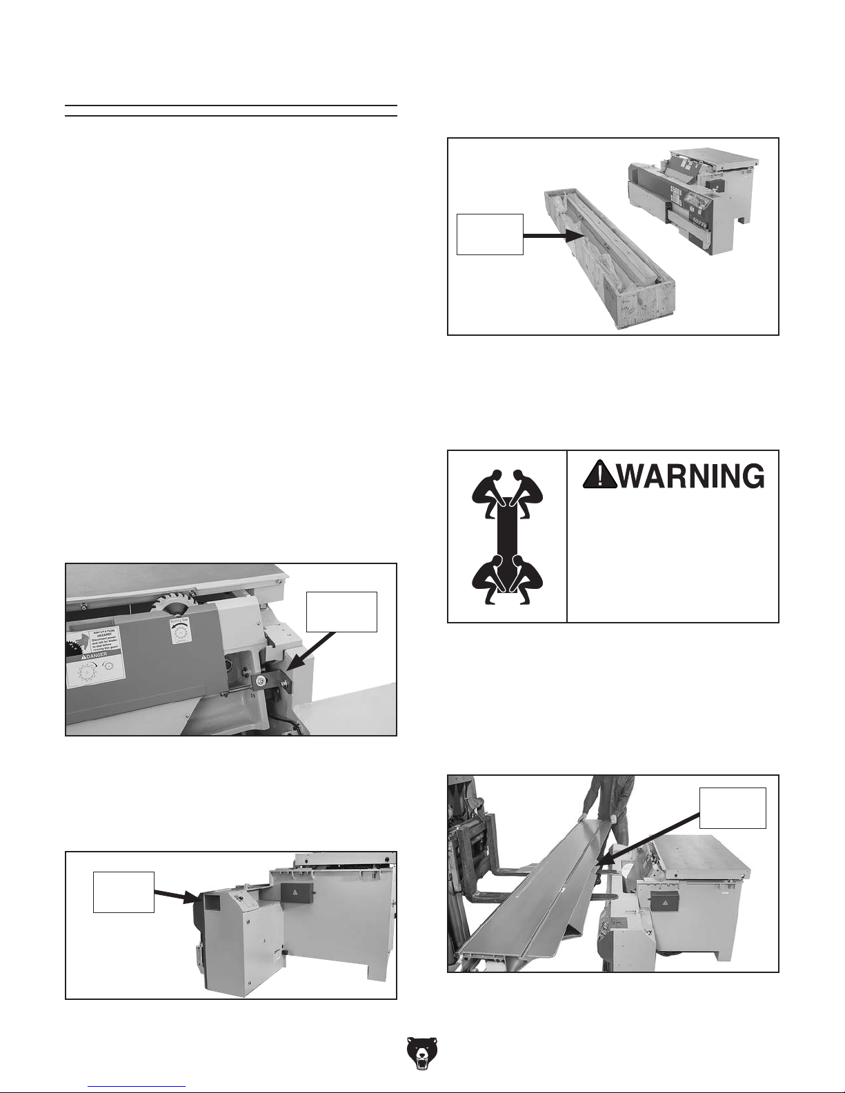
3. Place crate with sliding table in front of saw,
so beveled edge of table is facing away from
saw (see Figure 20).
Beveled
Edge
If a forklift is not available, the sliding table can
be lifted into place by four strong people—having one lift from each corner. The only other part
of the assembly that requires additional help is
installation of the extension tables and blade
guard arm.
To assemble sliding table saw:
1. Remove red shipping brace shown in Figure
18, then re-install brace fasteners.
Shipping
Brace
Figure 18. Location of shipping brace that must
be removed
Figure 20. Sliding table crate positioned in front
of saw to prepare for installation.
4. Remove sides of crate and plastic bag from
around sliding table.
Lifting sliding table or
other heavy components
without proper assistance
or equipment may result
in strains, back injuries,
crushing injuries, or
property damage.
5. Place cardboard onto forks, then position
sliding table right side up onto forks, so beveled edge faces forward.
6. Lift sliding table just higher than saw (see
Figure 21), then carefully place table on saw.
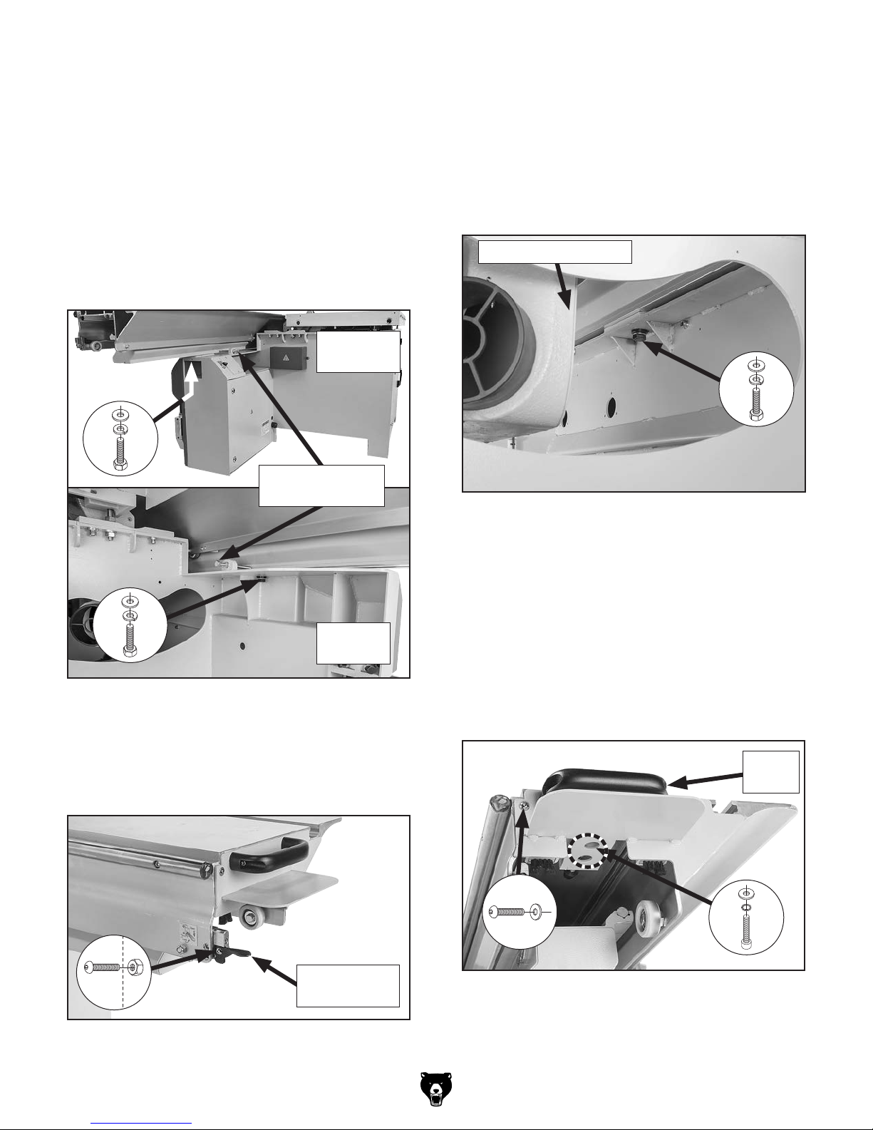
2. Remove cover on side of control panel (see
Figure 19).
Access
Area
Figure 19. Location of access area.
-26-
Beveled
Edge
Figure 21. Positioning sliding table onto base.
Model G0772 (Mfd. Since 05/15)
7. Visually align mounting holes in sliding table
base and saw, then install (2) M14-2 x 45
hex bolts with (2) 14mm lock washers and (2)
14mm flat washers through into ends of table
base (see Figure 22). Finger tighten only, for
now.
8. Push sliding table against parallelism adjustment bolts (see Figure 22), then final tighten
hex bolts from last step. The parallelism
bolts are preset at the factory and should not
require any adjustment.
Right Side
of Saw
x 1
Parallelism
Adjustment Bolts
10. Move sliding table lever down to unlock sliding table. Move table right to access center
mounting hole, located near saw blade.
11. Install (1) M14-2 x 45 hex bolt with (1)
14mm lock washer and (1) 14mm flat washer
through saw into center of table base (see
Figure 24). Finger tighten only, for now.
Cabinet Access Hole
x 1
Figure 24. Center bolt installed to secure sliding
table base to saw.
x 1
Left Side
of Saw
Figure 22. Location to install hex bolts in sliding
table base and saw.
9. Install sliding table lever using (1) pre-installed
M6-1 x 20 button head cap screw and (1)
M6-1 hex nut (see Figure 23).
12. Re-install cover removed in Step 2.
13. Install end handle with (2) pre-installed M5-.8
x 12 button head cap screws and (2) 5mm flat
washers (see Figure 25).
14. Finish securing end handle with (2) M6-1 x 15
cap screws, (2) 6mm conical lock washers,
and (2) 6mm flat washers (see Figure 25).
End
Handle
x 2
x 2
x 1
Figure 23. Sliding table lever installed.
Model G0772 (Mfd. Since 05/15)
Sliding Table
Lever
Figure 25. End handle installed on front (right)
side of sliding table.
-27-
15. Install end plate onto rear (left) end of sliding
table with (2) pre-installed M5-.8 x 12 button
head cap screws and (2) 5mm flat washers
(see Figure 26). Finish by installing (2) M6-1
x 15 cap screws, (2) 6mm conical lock washers, and (2) 6mm flat washers.
17. Place straightedge across cast iron table
and small extension table. Loosen hex bolts
shown in Figure 28 and adjust small extension table as necessary to level it flush with
cast iron table. Final tighten hex bolts with
wrench.
x 2
x 2
Figure 26. End plate installed on rear (left) end
of sliding table.
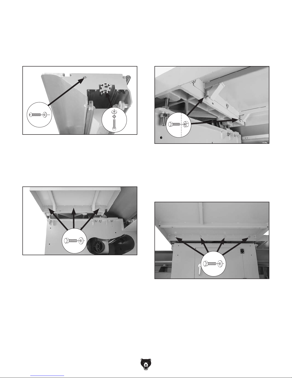
16. Install small extension table with (3) preinstalled M8-1.25 x 20 hex bolts and (3) 8mm
flat washers, as shown in Figure 27. Finger
tighten only, for now.
Figure 28. Location of hex bolts used to level
small extension table.
18. Install large extension table with (4) preinstalled M8-1.25 x 20 hex bolts and (4) 8mm
flat washers (see Figure 29). Use straightedge to verify extension table and cast iron
table are flush, then tighten bolts.
Figure 27. Underside view of small extension
table attached to cast iron table.
-28-
Figure 29. Underside view of large extension
table attached to cast iron table.
Model G0772 (Mfd. Since 05/15)
 Loading...