

Page 1

MODEL G0758
MILL/DRILL
OWNER'S MANUAL
(For models manufactured since 02/14)
Shown with Optional Stand
(Model T26612)
COPYRIGHT © MAY, 2014 BY GRIZZLY INDUSTRIAL, INC.
WARNING: NO PORTION OF THIS MANUAL MAY BE REPRODUCED IN ANY SHAPE
OR FORM WITHOUT THE WRITTEN APPROVAL OF GRIZZLY INDUSTRIAL, INC.
#DM16290 PRINTED IN CHINA
V1. 0 5.14
Page 2

This manual provides critical safety instructions on the proper setup,
operation, maintenance, and service of this machine/tool. Save this
document, refer to it often, and use it to instruct other operators.
Failure to read, understand and follow the instructions in this manual
may result in fire or serious personal injury—including amputation,
electrocution, or death.
The owner of this machine/tool is solely responsible for its safe use.
This responsibility includes but is not limited to proper installation in
a safe environment, personnel training and usage authorization,
proper inspection and maintenance, manual availability and comprehension, application of safety devices, cutting/sanding/grinding tool
integrity, and the usage of personal protective equipment.
The manufacturer will not be held liable for injury or property damage
from negligence, improper training, machine modifications or misuse.
Some dust created by power sanding, sawing, grinding, drilling, and
other construction activities contains chemicals known to the State
of California to cause cancer, birth defects or other reproductive
harm. Some examples of these chemicals are:
• Lead from lead-based paints.
• Crystalline silica from bricks, cement and other masonry products.
• Arsenic and chromium from chemically-treated lumber.
Your risk from these exposures varies, depending on how often you
do this type of work. To reduce your exposure to these chemicals:
Work in a well ventilated area, and work with approved safety equipment, such as those dust masks that are specially designed to filter
out microscopic particles.
Page 3

Table of Contents
INTRODUCTION ............................................... 2
Machine Description ...................................... 2
Contact Info.................................................... 2
Manual Accuracy ........................................... 2
Identification ................................................... 3
Controls & Components ................................. 4
SECTION 1: SAFETY ....................................... 7
Safety Instructions for Machinery .................. 7
Additional Safety for Mills/Drills ..................... 9
SECTION 2: POWER SUPPLY ...................... 10
Availability .................................................................10
Full-Load Current Rating ...........................................10
110V Circuit Requirements .......................................10
Grounding & Plug Requirements ..............................11
Extension Cords ........................................................11
SECTION 3: SETUP ....................................... 12
Needed for Setup ......................................... 12
Unpacking .................................................... 12
Inventory ...................................................... 13
Cleanup ........................................................ 14
Site Considerations ...................................... 15
Lifting & Placing ........................................... 16
Bench Mounting ........................................... 17
Assembly ..................................................... 17
Joining Drill Chuck & Arbor .......................... 18
Lubricating Mill/Drill ...................................... 18
Test Run ...................................................... 19
Spindle Break-In .......................................... 20
Inspections & Adjustments .......................... 20
SECTION 5: ACCESSORIES ......................... 27
SECTION 6: MAINTENANCE ......................... 28
Schedule ...................................................... 28
Cleaning and Protecting .............................. 28
Lubrication ................................................... 28
Table and Column Ways ...........................................29
Z-Axis Leadscrews ....................................................29
Table Leadscrews .....................................................30
Headstock Gears ......................................................30
Quill Outside Surface ................................................31
Quill Rack .................................................................31
Replacing DRO Battery ............................... 31
SECTION 7: SERVICE ................................... 32
Troubleshooting ........................................... 32
Adjusting Gibs .............................................. 34
Adjusting Leadscrew Backlash .................... 34
Brush Replacement ..................................... 35
SECTION 8: WIRING ...................................... 36
Wiring Safety Instructions ............................ 36
G0758 Wiring Overview ............................... 37
G0758 Wiring ............................................... 38
SECTION 9: PARTS ....................................... 40
Column ......................................................... 40
Electrical Box ............................................... 42
Headstock .................................................... 43
Chip Guard................................................... 45
Labels & Cosmetics ..................................... 46
WARRANTY & RETURNS ............................. 49
SECTION 4: OPERATIONS ........................... 21
Operation Overview ..................................... 21
Downfeed Controls ...................................... 22
Identification ..............................................................22
Using DRO ................................................................22
Using Coarse Downfeed ...........................................22
Using Fine Downfeed ................................................22
Headstock Movement .................................. 23
Raising/Lowering Headstock .....................................23
Tilting Headstock .......................................................23
Table Travel ................................................. 24
Graduated Dials ........................................................24
X-Axis Handwheel .....................................................24
Y-Axis Handwheel .....................................................24
Installing/Removing Tooling ......................... 25
Installing Tooling .......................................................25
Removing Tooling .....................................................26
Spindle Speed.............................................. 26
Determining Spindle Speed ......................................26
Page 4
INTRODUCTION
We are proud to provide a high-quality owner’s
manual with your new machine!
We
instructions, specifications, drawings, and photographs
contained inside. Sometimes we make mistakes,
but
also
means that
you receive
will be slightly different than what is shown in
the manual
If you find this to be the case, and the difference
between the manual and machine leaves you
confused about a procedure
for an updated version. W
manuals
and
www.grizzly.com
Alternatively, you can call our Technical Support
for help. Before calling, please write down the
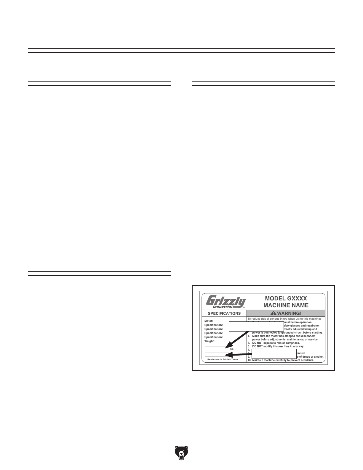
Manufacture Date
stamped
into the machine ID label (see below). This information helps us determine if updated documentation is available for your machine.
We stand behind our machines. If you have
any questions or need help, use the information
below to contact us. Before contacting, please get
the serial number and manufacture date of your
machine. This will help us help you faster.
We want your feedback on this manual. What did
you like about it? Where could it be improved?
Please take a few minutes to give us feedback.
Machine Description
The Model G0758 is a high-precision mill/drill with
a 600 Watt (
with low speed gearing for maximum torque in the
lowest RPM range.
This mill/drill has a spindle-to-table distance of 9"
with a 13
features manual downfeed controls with a variable
spindle speed range from 50–2000 RPM. DRO's
for both the spindle speed and spindle downfeed
stroke allow precise operation. The headstock tilts
45° left/right and moves in the Z-axis along dovetailed ways for maximum precision.
The large 5
(X-axis) and 5
ment is along precision-ground dovetailed ways.
An optional stand (Model T26612) is available for
purchase at www.grizzly.com.
3
⁄4 HP) high-torque, low noise motor,
1
⁄4" swing. It has an R-8 spindle size and
1
⁄2 " x 1911⁄16" table features manual 13"
1
⁄2 " (Y-axis) travel. All table move-
Contact Info
Manual Accuracy
made every effort to be exact with the
our policy of continuous improvement
sometimes the machine
.
, check our website
e post current
manual updates for free on our website at
.
and Serial Number
Grizzly Technical Support
1203 Lycoming Mall Circle
Muncy, PA 17756
Phone: (570) 546-9663
Email: techsupport@grizzly.com
Grizzly Documentation Manager
P.O. Box 2069
Bellingham, WA 98227-2069
Email: manuals@grizzly.com
Manufacture Date
Serial Number
-2-
Model G0758 (Mfd. Since 2/14)
Page 5
Identification
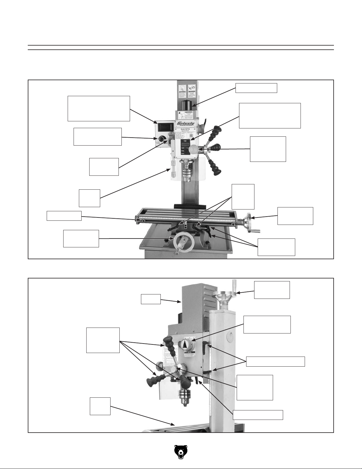
Become familiar with the names and locations of the controls and features shown below to better understand
the instructions in this manual.
Drawbar Cap
Spindle Speed
Digital Readout Unit
(DRO)
Variable-Speed
Knob
ON/OFF
Buttons
Spindle Position
Digital Readout Unit
(DRO)
Fine
Downfeed
Handwheel
Table Stop
Y-Axis
Handwheel
Chip
Guard
Coarse
Downfeed
Handles
X-Axis
Lock
Levers
X-Axis
Handwheel
Y-Axis Lock
Levers
Figure 1. Front identification.
Z-Axis
Handwheel
Motor
High/Low
Gearbox Knob
Work
Table
Model G0758 (Mfd. Since 2/14)
Z-Axis Lock Levers
Downfeed
Selector
Knob
Quill Lock Lever
Figure 2. Right side identification.
-3-
Page 6
Controls &
To reduce your risk of
serious injury, read this
entire manual BEFORE
F. Coarse Downfeed Handle: Provides coarse
control over vertical quill travel.
Components
using machine.
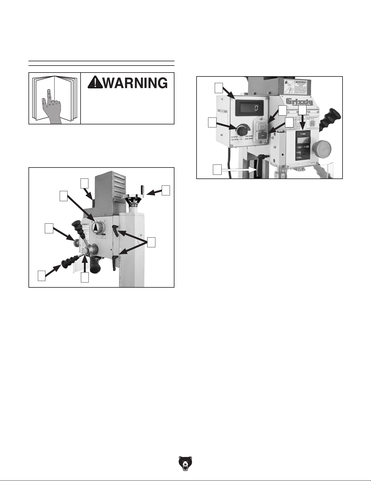
Refer to Figures 3 & 4 and the following descriptions to become familiar with the basic controls of
this machine.
B
C
A
G
G. Fine Downfeed Handwheel: Provides fine
control over vertical quill travel.
I
J
H
M
Figure 4. G0758 controls (front side).
H. Variable-Speed Knob: Controls spindle
speed.
I. Variable-Speed Digital Readout Unit
(DRO): Displays spindle speed.
L
K
D
F
Figure 3. G0758 controls (right side).
A. High/Low Gearbox Knob: Selects low gear
"L" for maximum torque from 50–1000 RPM,
or high gear "H" for 100–2000 RPM.
B. Drawbar Cap/Drawbar: Drawbar secures
collets and tooling in the spindle.
C. Z-Axis Handwheel: Raises and lowers head-
stock.
D. Z-Axis Travel Locks: Locks position of
headstock to column.
E. Downfeed Selector Knob: Selects between
fine and coarse vertical quill travel.
E
J. ON Button: Supplies power for spindle rota-
tion.
K. OFF Button: Disconnects power for spindle
rotation.
L. Spindle Downfeed Digital Readout Unit
(DRO): Displays a precise reading of verti-
cal positioning of spindle. It can be zeroed
at any position and manually increased or
decreased independent of spindle position
when operation requires it.
M. Quill Lock Lever: Locks vertical position of
quill when tightened.
-4-
Model G0758 (Mfd. Since 2/14)
Page 7

MACHINE DATA
SHEET
Customer Service #: (570) 546-9663 · To Order Call: (800) 523-4777 · Fax #: (800) 438-5901
MODEL G0758 MILL/DRILL
Product Dimensions:
Weight.............................................................................................................................................................. 161 lbs.
Width (side-to-side) x Depth (front-to-back) x Height............................................................... 19-3/4 x 21 x 30-1/4 in.
Footprint (Length x Width)............................................................................................................... 16-1/2 x 15-3/4 in.
Shipping Dimensions:
Type.......................................................................................................................................................... Wood Crate
Content........................................................................................................................................................... Machine
Weight.............................................................................................................................................................. 176 lbs.
Length x Width x Height....................................................................................................................... 24 x 22 x 32 in.
Electrical:
Power Requirement........................................................................................................... 110V, Single-Phase, 60 Hz
Full-Load Current Rating........................................................................................................................................ 10A
Minimum Circuit Size.............................................................................................................................................. 15A
Connection Type....................................................................................................................................... Cord & Plug
Power Cord Included.............................................................................................................................................. Yes
Power Cord Length................................................................................................................................................. 5 ft.
Power Cord Gauge......................................................................................................................................... 16 AWG
Plug Included.......................................................................................................................................................... Yes
Included Plug Type................................................................................................................................................ 5-15
Switch Type........................................................................................... ON/OFF Push Button Switch w/Safety Cover
Motors:
Main
Type......................................................................................................................................... High-Torque DC
Horsepower................................................................................................................................ 600W (3/4 HP)
Phase............................................................................................................................................ Single-Phase
Amps............................................................................................................................................................ 10A
Speed................................................................................................................................................ 4500 RPM
Power Transfer ................................................................................................................................. Gear Drive
Bearings....................................................................................................... Shielded and Permanently Sealed
Main Specifications:
Operation Info
Spindle Travel.............................................................................................................................................. 2 in.
Max Distance Spindle to Column.......................................................................................................... 6-5/8 in.
Max Distance Spindle to Table.................................................................................................................... 9 in.
Longitudinal Table Travel (X-Axis)............................................................................................................. 13 in.
Cross Table Travel (Y-Axis).................................................................................................................. 5-1/2 in.
Vertical Head Travel (Z-Axis)................................................................................................................ 8-1/4 in.
Head Tilt (Left/Right)........................................................................................................ Left 45, Right 45 deg.
Drilling Capacity for Cast Iron................................................................................................................... 5/8 in.
Drilling Capacity for Steel......................................................................................................................... 1/2 in.
End Milling Capacity................................................................................................................................. 5/8 in.
Face Milling Capacity................................................................................................................................... 2 in.
Model G0758 (Mfd. Since 2/14)
-5-
Page 8

Table Info
Table Length....................................................................................................................................
Table Width...........................................................................................................................................
Table Thickness.................................................................................................................................... 1-7/8 in.
Number of T-Slots............................................................................................................................................ 3
T-Slot Size................................................................................................................................................ 3/8 in.
T-Slots Centers...................................................................................................................................... 1-1/2 in.
Spindle Info
Spindle Taper............................................................................................................................................... R-8
Number of Vertical Spindle Speeds...................................................................................................... Variable
Range of Vertical Spindle Speeds............................................................................................... 50–2000 RPM
Quill Diameter......................................................................................................................................... 2.36 in.
Drawbar Thread Size............................................................................................................................. 7/16-20
Drawbar Length..................................................................................................................................... 9-7/8 in.
Spindle Bearings......................................................................................................... Tapered Roller Bearings
Construction
Spindle Housing/Quill........................................................................................................................... Cast Iron
Table.................................................................................................................................................... Cast Iron
Head.................................................................................................................................................... Cast Iron
Column/Base....................................................................................................................................... Cast Iron
Paint Type/Finish.................................................................................................................................... Enamel
Other
Optional Stand........................................................................................................................................ T26612
19-11/16 in.
5-1/2 in.
Other Specifications:
Country of Origin ................................................................................................................................................ China
Warranty ........................................................................................................................................................... 1 Year
Serial Number Location .................................................................................................................................. ID Label
ISO 9001 Factory .................................................................................................................................................. Yes
CSA, ETL, or UL Certified/Listed ............................................................................................................................ No
Features:
Dovetail headstock column and table ways
High-torque, low-noise DC motor
Variable-speed spindle with DRO
Spindle elevation DRO
3-Axis precision handwheel control
Coarse and fine spindle downfeed
2-Speed gearbox
Zero-setting dials on handwheels
Handwheel dials feature 0.002" graduations
Accessories Included:
Drill chuck 3-16mm with B16 taper
Drill chuck arbor B16 x R8
Open-ended and hex wrenches
Toolbox
-6-
Model G0758 (Mfd. Since 2/14)
Page 9

SECTION 1: SAFETY
For Your Own Safety, Read Instruction
Manual Before Operating This Machine
The purpose of safety symbols is to attract your attention to possible hazardous conditions.
This manual uses a series of symbols and signal words intended to convey the level of importance of the safety messages. The progression of symbols is described below. Remember that
safety messages by themselves do not eliminate danger and are not a substitute for proper
accident prevention measures. Always use common sense and good judgment.
Indicates an imminently hazardous situation which, if not avoided,
WILL result in death or serious injury.
Indicates a potentially hazardous situation which, if not avoided,
COULD result in death or serious injury.
Indicates a potentially hazardous situation which, if not avoided,
MAY result in minor or moderate injury. It may also be used to alert
against unsafe practices.
This symbol is used to alert the user to useful information about
NOTICE
proper operation of the machine.
Safety Instructions for Machinery
OWNER’S MANUAL. Read and understand this
owner’s manual BEFORE using machine.
TRAINED OPERATORS ONLY. Untrained operators have a higher risk of being hurt or killed.
Only allow trained/supervised people to use this
machine. When machine is not being used, disconnect power, remove switch keys, or lock-out
machine to prevent unauthorized use—especially
around children. Make workshop kid proof!
DANGEROUS ENVIRONMENTS. Do not use
machinery in areas that are wet, cluttered, or have
poor lighting. Operating machinery in these areas
greatly increases the risk of accidents and injury.
MENTAL ALERTNESS REQUIRED. Full mental
alertness is required for safe operation of machinery. Never operate under the influence of drugs or
alcohol, when tired, or when distracted.
ELECTRICAL EQUIPMENT INJURY RISKS. You
can be shocked, burned, or killed by touching live
electrical components or improperly grounded
machinery. To reduce this risk, only allow qualified
service personnel to do electrical installation or
repair work, and always disconnect power before
accessing or exposing electrical equipment.
DISCONNECT POWER FIRST.
nect machine from power supply BEFORE making
adjustments, changing tooling, or servicing machine.
This prevents an injury risk from unintended startup
or contact with live electrical components.
EYE PROTECTION. Always wear ANSI-approved
safety glasses or a face shield when operating or
observing machinery to reduce the risk of eye
injury or blindness from flying particles. Everyday
eyeglasses are NOT approved safety glasses.
Always discon-
Model G0758 (Mfd. Since 2/14)
-7-
Page 10

WEARING PROPER APPAREL. Do not wear
clothing, apparel or jewelry that can become
entangled in moving parts. Always tie back or
cover long hair. Wear non-slip footwear to avoid
accidental slips, which could cause loss of workpiece control.
HAZARDOUS DUST. Dust created while using
machinery may cause cancer, birth defects, or
long-term respiratory damage. Be aware of dust
hazards associated with each workpiece material,
and always wear a NIOSH-approved respirator to
reduce your risk.
HEARING PROTECTION. Always wear hearing protection when operating or observing loud
machinery. Extended exposure to this noise
without hearing protection can cause permanent
hearing loss.
REMOVE ADJUSTING TOOLS. Tools left on
machinery can become dangerous projectiles
upon startup. Never leave chuck keys, wrenches,
or any other tools on machine. Always verify
removal before starting!
USE CORRECT TOOL FOR THE JOB. Only use
this tool for its intended purpose—do not force
it or an attachment to do a job for which it was
not designed. Never make unapproved modifications—modifying tool or using it differently than
intended may result in malfunction or mechanical
failure that can lead to personal injury or death!
AWKWARD POSITIONS. Keep proper footing
and balance at all times when operating machine.
Do not overreach! Avoid awkward hand positions
that make workpiece control difficult or increase
the risk of accidental injury.
CHILDREN & BYSTANDERS. Keep children and
bystanders at a safe distance from the work area.
Stop using machine if they become a distraction.
FORCING MACHINERY. Do not force machine.
It will do the job safer and better at the rate for
which it was designed.
NEVER STAND ON MACHINE. Serious injury
may occur if machine is tipped or if the cutting
tool is unintentionally contacted.
STABLE MACHINE. Unexpected movement during operation greatly increases risk of injury or
loss of control. Before starting, verify machine is
stable and mobile base (if used) is locked.
USE RECOMMENDED ACCESSORIES. Consult
this owner’s manual or the manufacturer for recommended accessories. Using improper accessories will increase the risk of serious injury.
UNATTENDED OPERATION. To reduce the
risk of accidental injury, turn machine OFF and
ensure all moving parts completely stop before
walking away. Never leave machine running
while unattended.
MAINTAIN WITH CARE. Follow all maintenance
instructions and lubrication schedules to keep
machine in good working condition. A machine
that is improperly maintained could malfunction,
leading to serious personal injury or death.
CHECK DAMAGED PARTS. Regularly inspect
machine for any condition that may affect safe
operation. Immediately repair or replace damaged
or mis-adjusted parts before operating machine.
MAINTAIN POWER CORDS. When disconnecting cord-connected machines from power, grab
and pull the plug—NOT the cord. Pulling the cord
may damage the wires inside. Do not handle
cord/plug with wet hands. Avoid cord damage by
keeping it away from heated surfaces, high traffic
areas, harsh chemicals, and wet/damp locations.
GUARDS & COVERS. Guards and covers reduce
accidental contact with moving parts or flying
debris. Make sure they are properly installed,
undamaged, and working correctly.
-8-
EXPERIENCING DIFFICULTIES. If at any time
you experience difficulties performing the intended operation, stop using the machine! Contact our
Technical Support at (570) 546-9663.
Model G0758 (Mfd. Since 2/14)
Page 11

Additional Safety for Mills/Drills
The primary risks of operating a Mill/Drill are as follows: You can be seriously injured or killed
by getting clothing, jewelry, or long hair entangled with rotating cutter. You can be severely cut
or your fingers can be amputated by contacting the rotating cutter. You can be blinded or struck
with great force by broken cutting tools, metal chips, workpieces, or adjustment tools thrown
from the rotating spindle. To reduce your risk of serious injury when operating this machine,
completely heed and understand the following:
UNDERSTAND ALL CONTROLS. Make sure you
understand the function and proper use of all controls before starting. This will help you avoid making mistakes that result in serious injury.
WEAR FACE SHIELD. Always wear a face shield
in addition to safety glasses. This provides more
complete protection for your face than safety
glasses alone.
REMOVE CHUCK KEY & SPINDLE TOOLS.
Always remove chuck key, drawbar wrench, and
other tools used on the spindle immediately after
use. This will prevent them from being thrown by
the spindle upon startup.
PROPERLY SECURE CUTTER. Firmly secure
cutting tool or drill bit so it does not fly out of spindle during operation.
USE CORRECT SPINDLE SPEED. Follow recommended speeds and feeds for each size and
type of cutting tool. This helps ensure best cutting
results and avoid tool breakage during operation.
INSPECT CUTTING TOOL. Inspect cutting tools
for sharpness, chips, or cracks before each use.
Replace dull, chipped, or cracked cutting tools
immediately.
ALLOW SPINDLE TO STOP. To minimize your
risk of entanglement, always allow spindle to stop
on its own. DO NOT stop spindle using your hand
or any other object.
SECURE WORKPIECE TO TABLE. Clamp
workpiece to table or secure in a vise mounted to
table, so workpiece cannot unexpectedly shift or
spin during operation. NEVER hold workpiece by
hand during operation.
CLEAN MACHINE SAFELY. Metal chips or shavings can be razor sharp. DO NOT clear chips
by hand or compressed air that can force chips
farther into machine—use a brush or vacuum
instead. Never clear chips while spindle is turning.
PROPERLY MAINTAIN MACHINE. Keep machine
in proper working condition to help ensure that it
functions safely and all guards and other components work as intended. Perform routine inspections and all necessary maintenance. Never operate machine with damaged or worn parts that can
break or result in unexpected movement during
operation.
DISCONNECT POWER FIRST. To reduce risk of
electrocution or injury from unexpected startup,
make sure mill/drill is turned OFF, disconnected
from power, and all moving parts have come to
a complete stop before changing cutting tools or
starting any inspection, adjustment, or maintenance procedure.
POWER DISRUPTION. In the event of a local
power outage during operation, turn spindle switch
OFF to avoid a possible sudden startup once
power is restored.
Like all machinery there is potential danger when operating this machine. Accidents are frequently caused by lack of familiarity or failure to pay attention. Use this machine with respect
and caution to lessen the possibility of operator injury. If normal safety precautions are overlooked or ignored, serious personal injury may occur.
Model G0758 (Mfd. Since 2/14)
-9-
Page 12

SECTION 2: POWER SUPPLY
Before installing the machine, consider the availability and proximity of the required power supply
circuit. If an existing circuit does not meet the
requirements for this machine, a new circuit must
be installed. To minimize the risk of electrocution,
fire, or equipment damage, installation work and
electrical wiring must be done by an electrician or
qualified service personnel in accordance with all
applicable codes and standards.
Electrocution, fire, or
equipment damage may
occur if machine is not
correctly grounded and
connected to the power
The full-load current rating is the amperage a
machine draws at 100% of the rated output power.
On machines with multiple motors, this is the
amperage drawn by the largest motor or sum of all
motors and electrical devices that might operate
at one time during normal operations.
The full-load current is not the maximum amount
of amps that the machine will draw. If the machine
is overloaded, it will draw additional amps beyond
the full-load rating.
If the machine is overloaded for a sufficient length
of time, damage, overheating, or fire may result—
especially if connected to an undersized circuit.
To reduce the risk of these hazards, avoid overloading the machine during operation and make
sure it is connected to a power supply circuit that
meets the specified circuit requirements.
For your own safety and protection of
Note: Circuit requirements in this manual apply to
a dedicated circuit—where only one machine will
be running on the circuit at a time. If machine will
be connected to a shared circuit where multiple
machines may be running at the same time, consult an electrician or qualified service personnel to
ensure circuit is properly sized for safe operation.
A power supply circuit includes all electrical
equipment between the breaker box or fuse panel
in the building and the machine. The power supply circuit used for this machine must be sized to
safely handle the full-load current drawn from the
machine for an extended period of time. (If this
machine is connected to a circuit protected by
fuses, use a time delay fuse marked D.)
This machine is prewired to operate on a power
supply circuit that has a verified ground and meets
the following requirements:
Availability
Serious injury could occur if you connect
the machine to power before completing the
setup process. DO NOT connect to power
until instructed later in this manual.
110V Circuit Requirements
Nominal Voltage .................... 110V, 115V, 120V
Cycle ..........................................................60 Hz
Phase ........................................... Single-Phase
Power Supply Circuit ......................... 15 Amps
supply.
Full-Load Current Rating
Full-Load Current Rating at 110V ........ 8 Amps
-10 -
property, consult an electrician if you are
unsure about wiring practices or electrical
codes in your area.
Model G0758 (Mfd. Since 2/14)
Page 13
Improper connection of the equipment-grounding
wire can result in a risk of electric shock. The
wire with green insulation (with or without yellow
stripes) is the equipment-grounding wire. If repair
or replacement of the power cord or plug is necessary, do not connect the equipment-grounding
wire to a live (current carrying) terminal.
Check with a qualified electrician or service personnel if you do not understand these grounding
requirements, or if you are in doubt about whether
the tool is properly grounded. If you ever notice
that a cord or plug is damaged or worn, disconnect it from power, and immediately replace it with
a new one.
We do not recommend using an extension cord
with this machine.
cord, only use it if absolutely necessary and only
on a temporary basis.
Extension cords cause voltage drop, which may
damage electrical components and shorten motor
life. Voltage drop increases as the extension cord
size gets longer and the gauge size gets smaller
(higher gauge numbers indicate smaller sizes).
Any extension cord used with this machine must
contain a ground wire, match the required plug
and receptacle, and meet the following requirements:
Grounding & Plug Requirements
it will not fit the outlet, have a qualified
electrician install the proper outlet with a
This machine MUST be grounded. In the event
of certain malfunctions or breakdowns, grounding
reduces the risk of electric shock by providing a
path of least resistance for electric current.
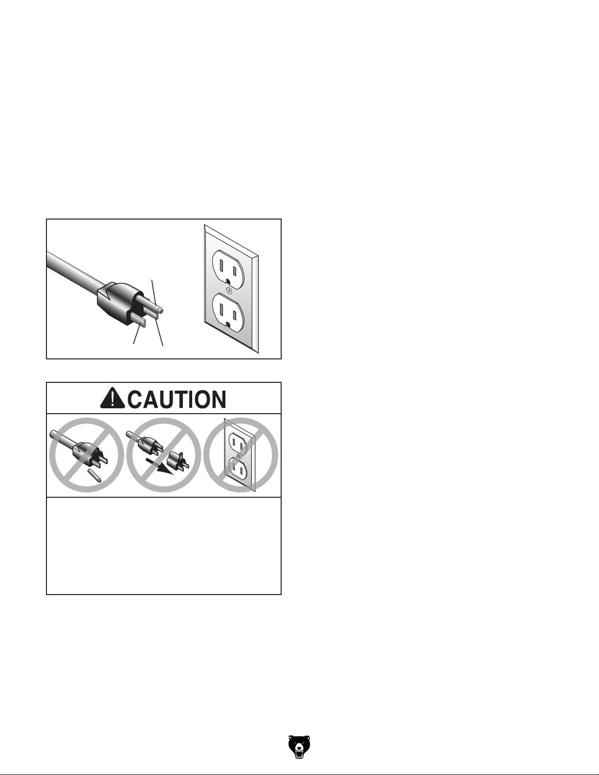
This machine is equipped with a power cord that
has an equipment-grounding wire and a grounding plug (similar to the figure below). The plug
must only be inserted into a matching receptacle
(outlet) that is properly installed and grounded in
accordance with all local codes and ordinances.
GROUNDED
5-15 RECEPTACLE
Grounding Prong
5-15 PLUG
Extension Cords
If you must use an extension
Neutral Hot
Figure 5. Typical 5-15 plug and receptacle.
SHOCK HAZARD!
Two-prong outlets do not meet the grounding
requirements for this machine. Do not modify
or use an adapter on the plug provided—if
verified ground.
Model G0758 (Mfd. Since 2/14)
Minimum Gauge Size ...........................16 AWG
Maximum Length (Shorter is Better).......50 ft.
-11-
Page 14
SECTION 3: SETUP
Your machine was carefully packaged for safe
transportation. Remove the packaging materials
from around your machine and inspect it. If you
discover any damage, please call us immediately
at (570) 546-9663
Save the containers and all packing materials for
possible inspection by the carrier or its agent.
Otherwise, filing a freight claim can be difficult.
When you are completely satisfied with the condition of your shipment, inventory the contents.
Keep children and pets away
from plastic bags or packing
materials shipped with this
get help from other people
Keep hair, clothing, and
ing parts at all times.
Entanglement can result
in death, amputation, or
Needed for Setup
This machine presents
serious injury hazards
to untrained users. Read
through this entire manual to become familiar with
controls and operations
before starting machine!
Wear safety glasses during
entire setup process!
HEAV Y LIF T!
Straining or crushing injury
may occur from improperly
lifting machine or some of
its parts. To reduce this risk,
The following are needed to complete the setup
process, but are not included with machine.
Description Qty
• Additional People ....................................... 1
• Safety Glasses ........................................... 1
• Cleaner/Degreaser (Page 14) .... As Needed
• Disposable Shop Rags ............... As Needed
• Forklift ......................................................... 1
• Lifting Sling (rated for at least 300 lbs.) ...... 1
• Mounting Hardware (Page 17) ... As Needed
• Brass Hammer (Page 26) .......................... 1
• Mineral Spirits (Page 18) ............ As Needed
• Wood Block (Page 18) ............................... 1
Unpacking
and use a forklift (or other
lifting equipment) rated for
weight of this machine.
jewelry away from mov-
severe crushing injuries!
-12-
for advice.
SUFFOCATION HAZARD!
machine. Discard immediately.
Model G0758 (Mfd. Since 2/14)
Page 15
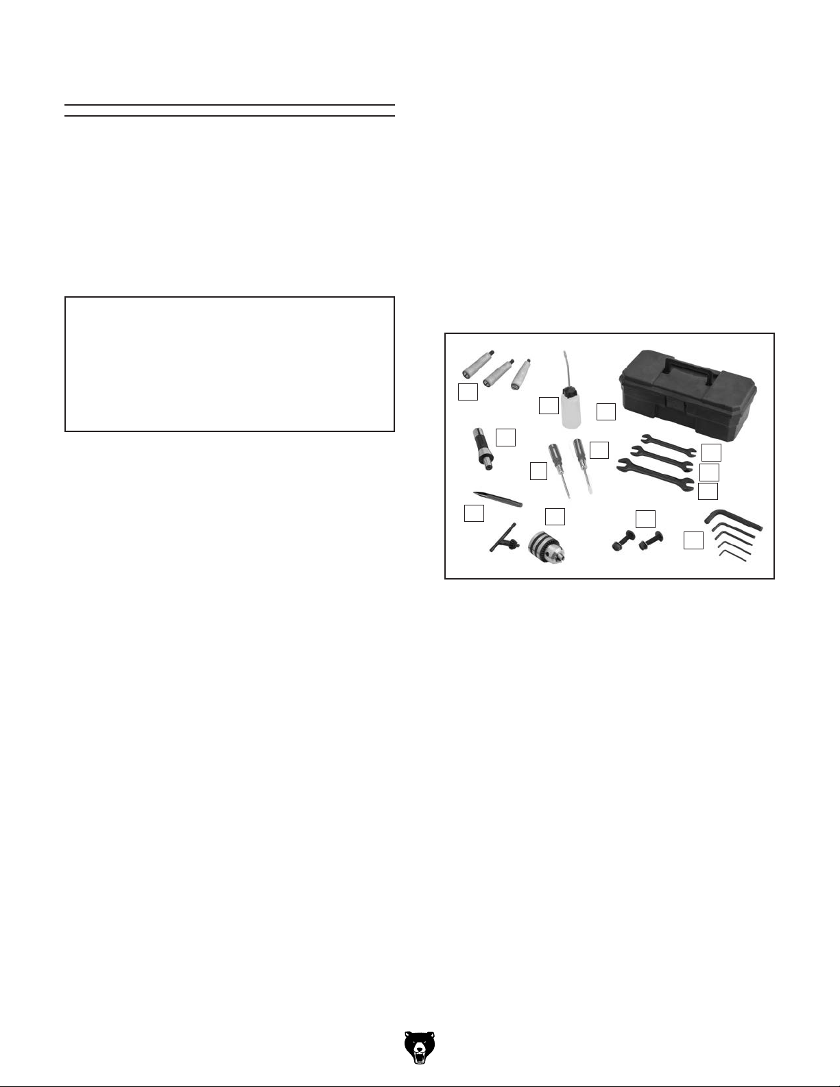
Inventory
The following is a list of items shipped with your
machine. Before beginning setup, lay these items
out and inventory them.
If any non-proprietary parts are missing (e.g. a
nut or a washer), we will gladly replace them; or
for the sake of expediency, replacements can be
obtained at your local hardware store.
NOTICE
If you cannot find an item on this list, carefully check around/inside the machine and
packaging materials. Often, these items get
lost in packaging materials while unpacking or they are pre-installed at the factory.
Inventory (Figure 6) Qty
A. Handwheel Handles w/Screws ................... 3
B. Bottle for Oil ............................................... 1
C. Toolbox ....................................................... 1
D. Drill Chuck Arbor R-8 x B-16 ...................... 1
E. Standard Screwdriver ................................. 1
F. Phillips Screwdriver .................................... 1
G. Spindle Pin ................................................. 1
H. Open-End Wrench 8/10mm ........................ 1
I. Open-End Wrench 12/14mm ...................... 1
J. Open-End Wrench 17/19mm ...................... 1
K. Drill Chuck 3–16mm w/Chuck Key ............. 1
L. T-Bolt M8-1.25 x 55 Assemblies ................. 2
M. Hex Wrenches 2.5, 3, 4, 5, 6mm ...... 1 Each
A
D
G
B
E
K
C
F
L
H
I
J
M
Figure 6. Inventory included with machine.
Model G0758 (Mfd. Since 2/14)
-13-
Page 16
The unpainted surfaces of your machine are
coated with a heavy-duty rust preventative that
prevents corrosion during shipment and storage.
This rust preventative works extremely well, but it
will take a little time to clean.
Be patient and do a thorough job cleaning your
machine. The time you spend doing this now will
give you a better appreciation for the proper care
of your machine's unpainted surfaces.
There are many ways to remove this rust preventative, but the following steps work well in a wide
variety of situations. Always follow the manufacturer’s instructions with any cleaning product you
use and make sure you work in a well-ventilated
area to minimize exposure to toxic fumes.
Before cleaning, gather the following:
• Disposable rags
• Cleaner/degreaser (WD•40 works well)
• Safety glasses & disposable gloves
• Plastic paint scraper (optional)
Basic steps for removing rust preventative:
1.
2.
3.
4.
Many cleaning solvents
work in a well-ventilated
Avoid chlorine-based solvents, such as
Cleanup
Gasoline and petroleum
products have low flash
points and can explode
or cause fire if used to
clean machinery. Avoid
using these products
to clean machinery.
Put on safety glasses.
Coat the rust preventative with a liberal
amount of cleaner/degreaser, then let it soak
for 5–10 minutes.
Wipe off the surfaces. If your cleaner/degreas-
er is effective, the rust preventative will wipe
off easily. If you have a plastic paint scraper,
scrape off as much as you can first, then wipe
off the rest with the rag.
are toxic if inhaled. Only
area.
NOTICE
acetone or brake parts cleaner, that may
damage painted surfaces.
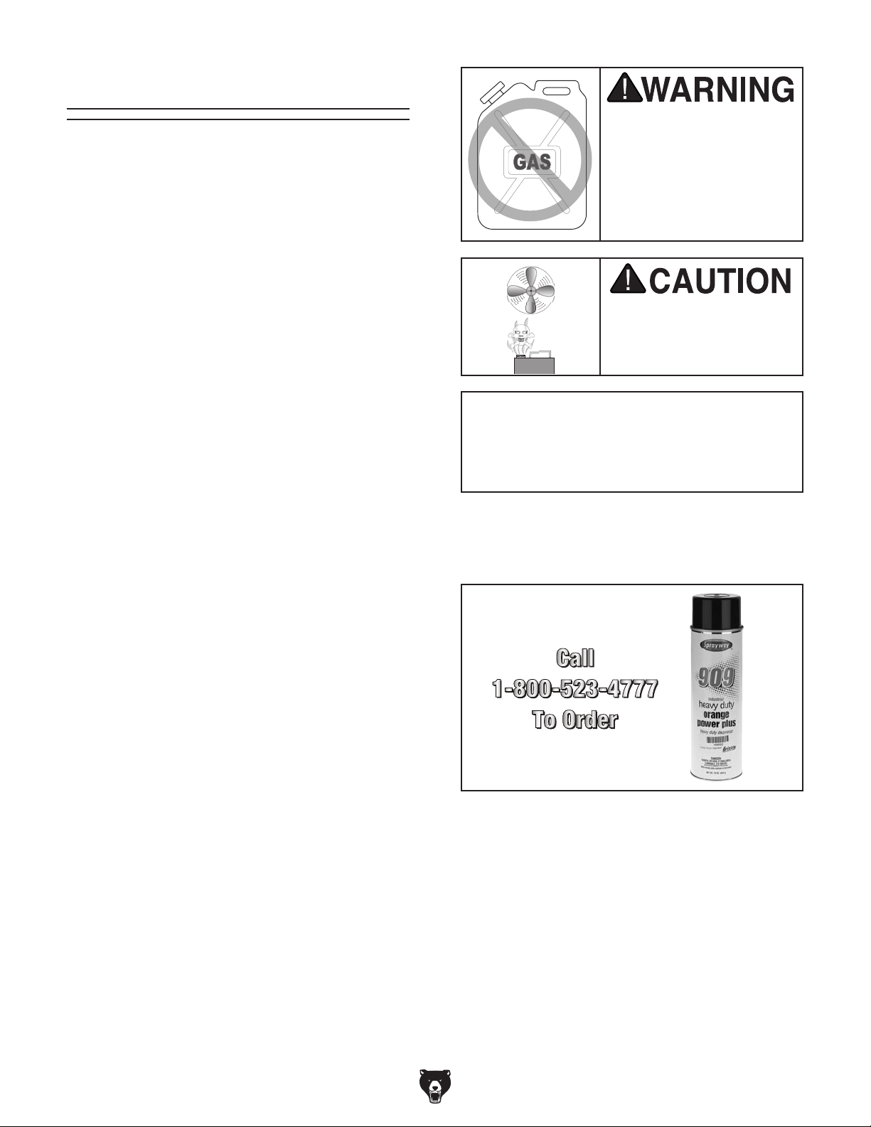
T23692—Orange Power Degreaser
A great product for removing the waxy shipping
grease from machine during clean up.
Figure 7. T23692 Orange Power Degreaser.
Repeat Steps 2–3 as necessary until clean,
then coat all unpainted surfaces with a quality
metal protectant to prevent rust.
-14-
Model G0758 (Mfd. Since 2/14)
Page 17

Site Considerations
Weight Load
Refer to the
of your machine. Make sure that the surface upon
which the machine is placed will bear the weight
of the machine, additional equipment that may be
installed on the machine, and the heaviest workpiece that will be used. Additionally, consider the
weight of the operator and any dynamic loading
that may occur when operating the machine.
Space Allocation
Consider the largest size of workpiece that will
be processed through this machine and provide
enough space around the machine for adequate
operator material handling or the installation of
auxiliary equipment. With permanent installations,
leave enough space around the machine to open
or remove doors/covers as required by the maintenance and service described in this manual.
See below for required space allocation.
Physical Environment
Extreme conditions for this type of machinery are
Place this machine near an existing power source.
other hazards. Make sure to leave enough space
Shadows, glare, or strobe effects that may distract
or impede the operator must be eliminated.
30
1
/
4
"
19
3
/
4
"
21
"
Machine Data Sheet for the weight
Children or untrained people
may be seriously injured by
this machine. Only install in an
access restricted location.
The physical environment where the machine is
operated is important for safe operation and longevity of machine components. For best results,
operate this machine in a dry environment that is
free from excessive moisture, hazardous chemicals, airborne abrasives, or extreme conditions.
generally those where the ambient temperature
range exceeds 41°–104°F; the relative humidity
range exceeds 20%–95% (non-condensing); or
the environment is subject to vibration, shocks,
or bumps.
Electrical Installation
Make sure all power cords are protected from
traffic, material handling, moisture, chemicals, or
around machine to disconnect power supply or
apply a lockout/tagout device, if required.
Lighting
Lighting around the machine must be adequate
enough that operations can be performed safely.
Figure 8. G0758 working clearances.
Model G0758 (Mfd. Since 2/14)
-15-
Page 18

Lifting & Placing
get help from other people
The Model G0758 mill/drill can be mounted to a
workbench or the Model T26612 optional stand
(see Figure 9). The optional stand is specifically
designed for Model G0758 and comes with predrilled mounting holes.
Figure 9. Model T26612 optional stand for
Model G0758.
To lift machine and place it in position:
1. Place shipping crate next to workbench (or
stand) where machine will be placed.
2. Use vertical handwheel to raise headstock as
far as possible (see Figure 10). Lock headstock in place to avoid sudden shifts during
lifting.
Lifting
Sling
Vertical
Handwheel
HEAV Y LIF T!
Straining or crushing injury
may occur from improperly
lifting machine or some of
its parts. To reduce this risk,
and use a forklift (or other
lifting equipment) rated for
weight of this machine.
Figure 10. Headstock positioned for lifting.
3. Hang sling from forklift fork and place it under
headstock, as shown in Figure 10. DO NOT
place sling over any controls or against any
components that may be damaged from the
force required for lifting.
4. Unbolt machine from pallet. Have an assistant on the ground steady machine to prevent
it from swinging and lift it slightly off the pallet
with forklift.
5. Carefully place machine onto workbench or
optional stand.
6. Mount machine to workbench following
instructions in Bench Mounting on Page
17 or to stand following instructions included
with stand.
-16 -
Model G0758 (Mfd. Since 2/14)
Page 19

Another option is a "Direct Mount" (see example
below) where the machine is secured directly to
the workbench with lag screws and washers.
Bench Mounting
The base of this machine has mounting holes
that allow it to be fastened to a workbench or
other mounting surface to prevent it from moving
during operation and causing accidental injury or
damage.
The strongest mounting option is a "Through
Mount" (see example below) where holes are
drilled all the way through the workbench—and
hex bolts, washers, and hex nuts are used to
secure the machine in place.
Assembly
Number of Mounting Holes ............................ 4
Diameter of Mounting Hardware .................
Hex
Bolt
Flat Washer
Machine Base
Workbench
1
⁄2"
Except for the handwheel handles, the mill/drill
was fully assembled at the factory.
Use a standard screwdriver to attach handwheel
handles (see Figures 13–14).
Table Handwheel
Handles
Figure 13. X- and Y-axis handwheel handles
attached.
Vertical Handwheel Handle
Flat Washer
Lock Washer
Figure 11. Example of a "Through Mount" setup.
Machine Base
Workbench
Hex Nut
Lag Screw
Flat Washer
Figure 14. Z-axis handwheel handle attached.
Figure 12. Example of a "Direct Mount" setup.
Model G0758 (Mfd. Since 2/14)
-17-
Page 20

Joining Drill Chuck
& Arbor
A B-16 x R8 arbor is included for the drill chuck
that comes with this machine. The following procedure describes how to install the arbor in the
chuck.
Lubricating Mill/Drill
The lubrication procedures highlighted in the
Lubrication subsection of SECTION 6:
MAINTENANCE must be completed before per-
forming the test run or spindle break-in.
After the arbor is installed in the drill chuck, it
is very difficult to separate the assembly. If you
would like to use a different chuck in the future,
we recommend getting a new arbor for that chuck.
Important: DO NOT install the drill chuck and
arbor into the spindle until AFTER the test run.
To join drill chuck and arbor:
1. Use mineral spirits to clean drill chuck and
arbor mating surfaces, especially the bore.
2. Retract chuck jaws completely into chuck.
3. Insert small end of arbor into chuck.
4. Hold assembly by arbor and tap chuck onto
a block of wood with medium force, as illustrated in Figure 15.
Damage caused by running the mill/drill
without first properly lubricating headstock
gears will not be covered under warranty.
Figure 15. Tapping drill chuck/arbor on block of
wood.
5. Attempt to separate drill chuck and arbor by
hand . If you can pull them apart, repeat this
procedure.
Note: Refer to Installing/Removing Tooling section on Page 25 for installing arbor into spindle
instructions.
-18-
Model G0758 (Mfd. Since 2/14)
Page 21

Test Run
Once assembly is complete, test run the machine
to ensure it is properly connected to power and
safety components are functioning properly.
If you find an unusual problem during the test run,
immediately stop the machine, disconnect it from
power, and fix the problem BEFORE operating the
machine again. The
table in the
SERVICE section of this manual can help.
DO NOT start machine until all preceding
setup instructions have been performed.
Operating an improperly set up machine
ed results that can lead to serious injury,
Serious injury or death can result from
Troubleshooting
using this machine BEFORE understanding
its controls and related safety information.
DO NOT operate, or allow others to operate,
machine until the information is understood.
3. Rotate variable-speed knob to lowest setting.
4. Rotate high/low gearbox knob to low "L" gear
setting (see Figure 17).
Note: When switching between gears, it may
be necessary to rotate spindle by hand so
gears will align and engage.
High/Low
Gearbox
Knob
may result in malfunction or unexpect-
death, or machine/property damage.
To test run mill/drill:
1. Make sure all tools and objects used during
setup are cleared away from machine.
2. Press OFF button (see Figure 16). This
will help prevent unexpected startup when
machine is connected to power.
ON Button
Variable-
Speed
Knob
Figure 16. Location of mill/drill controls (front).
Model G0758 (Mfd. Since 2/14)
OFF Button
Figure 17. Gearbox knob rotated to low setting.
5. Connect mill/drill to power supply.
6. Press ON button. Spindle should begin to
rotate clockwise (as viewed from top), and
machine should run smoothly with little or no
vibration or rubbing noises.
7. Press OFF button.
8. Open chip guard half way and press ON but-
ton. Machine should not start.
—If machine does start (with chip guard
opened half way), press OFF button and
immediately disconnect power to machine.
The chip guard safety feature is not working correctly. This safety feature must
work properly before proceeding with regular operations. Refer to Troubleshooting
table in this manual.
Congratulations! The Test Run is complete.
Continue to Spindle Break-In.
-19 -
Page 22

Spindle Break-In
The spindle break-in procedure distributes lubrication
reduce the risk
of early
if there are any "dry" spots
or areas where lubrication has settled in the bearings. You
efore
placing
for the
first time when the machine is new or if it has
been sitting idle for longer than 6 months.
Always start the spindle break-in at the lowest
speed to minimize wear if there
Allow the spindle to run long enough to warm up
and distribute the bearing grease, then incrementally increase spindle speeds, allowing the spindle
to run the same amount of time at each speed, until
reaching the maximum spindle speed. Following
the break-in procedure in this progressive manner helps minimize any potential wear that could
occur until lubrication is fully distributed.
tain the warranty. Failure to do this could
6. Rotate variable-speed knob to 100 RPM and
high/low gearbox knob to high "H".
7. Press ON button.
throughout the bearings to
bearing failure
must complete this procedure b
operational loads on the spindle
are dry spots.
You must complete this procedure to main-
cause rapid wear-and-tear of spindle bearings once they are placed under load.
To perform spindle break-in procedure:
1. Rotate variable-speed knob to 50 RPM and
high/low gearbox knob to low "L".
8. Run machine for a minimum of 10 minutes.
9. Without stopping spindle, use variable-speed
knob to run machine at 1000 and 2000 RPM
for 10 minutes each.
10. Press OFF button.
The spindle break-in of the machine is now
complete!
Inspections &
Adjustments
The following adjustments were performed at the
factory before the machine was shipped:
• Gib Adjustments ............................. Page 34
• Leadscrew Backlash
Adjustments .................................... Page 34
Be aware that these can change during the
shipping process. Pay careful attention to these
adjustments when first operating the machine. If
you find that the adjustments are not set to your
personal preferences, re-adjust them.
2. Press ON button.
3. Run spindle for minimum of 10 minutes.
4. Without stopping spindle, use variable-speed
knob to run machine at 500 and 1000 RPM
for 10 minutes each.
5. Press OFF button.
-20-
Model G0758 (Mfd. Since 2/14)
Page 23

SECTION 4: OPERATIONS
The purpose of this overview is to provide the novice machine operator with a basic understanding
of how the machine is used during operation, so
the
discussed later
in this manual
Due to the generic nature of this overview, it is
not intended to be an instructional guide. To learn
more about specific operations, read this entire
manual and
rienced
research outside of this manual by reading "howto" books, trade magazines, or websites.
To reduce your risk of
serious injury, read this
entire manual BEFORE
Operation Overview
machine controls/components
are easier to understand.
seek additional training from expe
machine operators, and do additional
To reduce risk of injury from unexpected
startup of spindle at high speeds, always
rotate variable-speed dial to the lowest setting before starting spindle.
To complete typical operation, operator does
the following:
1. Examines workpiece to make sure it is suit-
able for cutting/drilling.
2. Puts on personal protective equipment.
3. Securely clamps workpiece to table.
4. With machine disconnected from power,
installs correct tooling.
using machine.
To reduce risk of eye or face injury from
flying chips, always wear approved safety
glasses and face shield when operating this
machine.
If you are not experienced with this type
of machine, WE STRONGLY RECOMMEND
that you seek additional training outside of
this manual. Read books/magazines or get
formal training before beginning any projects. Regardless of the content in this section, Grizzly Industrial will not be held liable
for accidents caused by lack of training.
Model G0758 (Mfd. Since 2/14)
5. Adjusts headstock height above table.
6. Rotates variable-speed knob to lowest set-
ting.
7. Selects correct gear setting on gearbox.
8. Connects machine to power and presses ON
button and rotates variable-speed knob to
correct spindle speed.
9. Uses downfeed controls or table controls to
perform operation.
10. Presses OFF button and waits for spindle to
completely stop before removing workpiece,
changing tooling, or changing spindle speeds.
-21-
Page 24

O
O
Downfeed Controls
3. Press ZERO to "zero" readout at any time.
Current reading will be cleared and scale will
reset to 0.00.
Identification
D
B
C
A
Figure 18. Identification of downfeed controls.
A. Quill Lock Lever
B. Spindle Downfeed DRO
C. Fine Downfeed Handwheel
D. Coarse Downfeed Handle
To increase or decrease reading, press
button. This is useful when calibrating mill/
drill to known dimensions on a workpiece.
4. Press Power/ button when operation is complete.
or
Using Coarse Downfeed
E
1. Loosen downfeed selector knob to engage
coarse downfeed handles.
2. Loosen quill lock lever.
3. Turn on spindle DRO and zero it out.
4. Use coarse downfeed handles to raise and
lower spindle while referencing spindle DRO
for precise movement.
Using Fine Downfeed
1. Tighten downfeed selector knob to engage
fine downfeed handwheel.
E. Downfeed Selector Knob
Using DRO
1. Press Power/ button (see Figure 19). A
reading should appear on display.
Power
Button
in/mm
Button
v Button
Figure 19. Identification of DRO controls.
2. Press in/mm button to select inches or mil-
limeters. Each press of button switches
between units.
Zero
2. Loosen quill lock lever.
3. Turn on spindle DRO and zero it out.
4. Rotate fine downfeed handwheel to raise and
lower spindle while referencing spindle DRO
for precise movement.
-22-
Model G0758 (Mfd. Since 2/14)
Page 25

Headstock
Movement
Tilting Headstock
Tools Needed Qty
Wrench 19mm ................................................... 1
Wrench 14mm ................................................... 1
The headstock moves in the following ways:
• Travels up and down the column (Z-axis).
• Tilts 45° left or right relative to the table.
Raising/Lowering Headstock
1. DISCONNECT MACHINE FROM POWER!
2. Loosen both Z-axis lock levers shown in
Figure 20.
Z-Axis
Lock
Levers
To tilt headstock:
1. DISCONNECT MACHINE FROM POWER!
2. Support headstock with one hand, then loos-
en headstock center bolt and angle lock nut
(see Figure 22).
Center Bolt
Angle
Lock Nut
Tilt Scale
Figure 22. Headstock tilt controls.
Figure 20. Location of Z-axis lock levers.
3. Use vertical handwheel shown in Figure 21
to adjust headstock height.
Vertical
Handwheel
Figure 21. Location of Z-axis handwheel.
4. Retighten lock levers.
3. While watching tilt scale, rotate headstock to
required angle, then retighten center bolt and
angle lock nut to secure headstock.
Model G0758 (Mfd. Since 2/14)
-23-
Page 26

Table Travel
The table travels in two directions and is controlled by handwheels, as illustrated in Figure 23:
X-Axis Handwheel
Tool Needed Qty
Hex Wrench 5mm .............................................. 1
To use X-axis handwheel:
• X-axis (longitudinal)
• Y-axis (cross)
X-Axis or Longitudinal Travel
(Left & Right)
Y-Axis or
Cross Travel
(In & Out)
Figure 23. Possible directions of table travel.
Graduated Dials
The handwheels have graduated dials that are
used to determine table movement in 0.002"
increments, with one full revolution equalling
0.10 0 ".
Rotate graduated dial to a relative starting point
(see Figure 24).
Graduated Dial
1. Loosen both X-axis table locks shown in
Figure 25.
Note: To readjust positioning of table locks,
pull out and rotate.
Table Stops
X-Axis
Table Locks
Figure 25. X- and Y-axis table travel locks.
2. Position table stops along front of table to
restrict table travel.
Y-Axis
Table Locks
Figure 24. Graduated dial location.
3. Adjust X-axis graduated dial to zero, then use
handwheel to move table.
Y-Axis Handwheel
The saddle does not have limit stops. To move
the table along the Y-axis, loosen the Y-axis
table locks shown in Figure 25, then use the
handwheel in front of the table in the same manner as the X-axis handwheel.
-24-
Model G0758 (Mfd. Since 2/14)
Page 27

Installing/Removing
Tooling
The Model G0758 includes a 1–13mm drill chuck
with R-8 arbor (see Figure 26).
Tool Slot
3. Align tool slot (see Figure 26) with pin inside
spindle, then insert tooling into spindle until in
contacts drawbar.
Note: Height of drawbar inside spindle can
be changed by rotating adjustment nut (see
Figure 28).
Drawbar
Adjustment
Nut
Drawbar
Figure 26. 1–13mm drill chuck joined with R-8
arbor.
Cutting tools are sharp and
can easily cause cutting
injuries. Always protect
your hands with leather
gloves or shop rags when
handling cutting tools.
Installing Tooling
Tools Needed Qty
Spindle Pin ........................................................ 1
Wrench 8mm ..................................................... 1
To install tooling:
1. DISCONNECT MACHINE FROM POWER!
Spindle Pin
Figure 28. Components used when installing or
removing tooling.
4. Working from above, thread drawbar by hand
into tooling until it is snug.
5. Secure spindle with spindle pin and tighten
drawbar with wrench, as shown in Figure 28.
Note: Do not overtighten drawbar.
Overtightening makes tool removal difficult
and will damage arbor and threads.
6. Re-install drawbar cap.
2. Remove drawbar cap (see Figure 27).
Drawbar Cap
Figure 27. Location of drawbar cap.
Model G0758 (Mfd. Since 2/14)
-25-
Page 28

Removing Tooling
Tools Needed Qty
Spindle Pin ........................................................ 1
Wrench 8mm ..................................................... 1
Brass Hammer .................................................. 1
To remove tooling:
1. DISCONNECT MACHINE FROM POWER!
2. Remove drawbar cap and secure spindle
with spindle pin. Unthread drawbar from tooling one full rotation.
Spindle Speed
Using the correct spindle speed is important for
safe and satisfactory results, as well as maximizing tool life.
To set the spindle speed for operation, you will
need to: 1) Determine the best spindle speed for
the cutting/drilling task, and 2) adjust the gear box
knob and variable-speed knob to produce determined speed.
Note: Do not fully unthread tooling from
drawbar or the drawbar and tool threads
could be damaged in the next step.
3. Tap top of drawbar with brass hammer to
unseat taper.
4. Hold onto tooling with one hand and fully
unthread drawbar.
Determining Spindle Speed
Many variables affect the optimum spindle speed
to use for any given operation, but the two most
important are the recommended cutting speed
for the workpiece material and the diameter of
the cutting tool, as noted in the formula shown in
Figure 29.
*Recommended
Cutting Speed (FPM) x 12
Tool Dia. (in inches) x 3.14
Spindle
=
Speed
(RPM)
*Double if using carbide cutting tool
Figure 29. Formula for determining best spindle
speed.
Cutting speed, typically defined in feet per minute
(FPM), is the speed at which the edge of a tool
moves across the material surface.
-26-
A recommended cutting speed is an ideal speed
for cutting a type of material in order to produce
the desired finish and optimize tool life.
The books Machinery’s Handbook or Machine
Shop Practice, and some internet sites, provide excellent recommendations for which cutting
speeds to use when calculating the spindle speed.
These sources also provide a wealth of additional
information about the variables that affect cutting
speed and they are a good educational resource.
Also, there are a large number of easy-to-use
spindle speed calculators that can be found on
the internet. These sources will help you take into
account the applicable variables in order to determine the best spindle speed for the operation.
Model G0758 (Mfd. Since 2/14)
Page 29

SECTION 5: ACCESSORIES
Installing unapproved accessories may
order online at www.grizzly.com or call 1-800-523-4777
cause machine to malfunction, resulting in
serious personal injury or machine damage.
To reduce this risk, only install accessories
recommended for this machine by Grizzly.
NOTICE
Refer to our website or latest catalog for
additional recommended accessories.
G7156—4" (3 5⁄8") Precision Milling Vise
G7154—5" (4
G7155—6" (5
Swiveling Milling Vises feature perfectly aligned,
precision ground jaws, large Acme
easy-to-read 0°–360° scales.
1
⁄2") Precision Milling Vise
5
⁄8") Precision Milling Vise
®
screws and
G5562—SLIPIT
G5563—SLIPIT
G2871—Boeshield
G2870—Boeshield
H3788—G96
H3789—G96
®
1 Qt. Gel
®
12 Oz. Spray
®
T-9 12 Oz. Spray
®
®
Gun Treatment 12 Oz. Spray
®
Gun Treatment 4.5 Oz. Spray
T-9 4 Oz. Spray
Figure 32. Recommended products for
protecting cast iron/steel parts on machinery.
SB1365—South Bend Way Oil-ISO 68
T23964—Moly-D Multi-purpose NLGI #2
Grease
Figure 30. G7154 Precision Milling Vise.
T26612—Optional Stand for Model G0758
Figure 33. Recommended products for machine
lubrication.
Figure 31. T26612 optional stand for Model
G0758.
Model G0758 (Mfd. Since 2/14)
-27-
Page 30

SECTION 6: MAINTENANCE
accidental startup, always
disconnect machine from
Cleaning and
To reduce risk of shock or
power before adjustments,
maintenance, or service.
Schedule
For optimum performance from the machine, follow this maintenance schedule and refer to any
specific instructions given in this section.
Daily Check:
• Loose mounting bolts.
• Damaged tooling.
• Clean debris and built up grime off of machine.
• Worn or damaged wires.
• Any other unsafe condition.
Every 8 Hours of Operation:
• Lubricate table and column ways (Page 29).
• Lubricate quill outside surface (Page 31).
Protecting
Metal chips left on the machine that have been
soaked with water-based coolant will invite oxidation and a gummy residue build-up around the
moving parts. Use a brush and shop vacuum to
remove chips and debris from the working surfaces of the mill/drill. Never blow off the mill/drill
with compressed air, as this will force metal chips
deep into the mechanisms and may cause injury
to yourself or bystanders.
Remove any rust build-up from unpainted cast
iron surfaces of mill/drill and treat with a nonstaining lubricant after cleaning.
Protect other unpainted cast iron surfaces with
regular applications of products like G96
Treatment, SLIPIT
Accessories on Page 27 for more details.)
®
, or Boeshield® T-9. (See
®
Gun
Lubrication
Every 40 Hours of Operation:
• Lubricate table leadscrews (Page 30).
Every 90 Hours of Operation:
• Headstock gears (Page 30).
• Lubricate quill rack (Page 31).
Every 120 Hours of Operation:
• Lubricate column leadscrew (Page 29).
-28-
An essential part of lubrication is cleaning the
components before lubricating them.
This step is critical because grime and chips build
up on lubricated components over time, which
makes them hard to move.
Clean all exterior components in this section with
mineral spirits, shop rags, and brushes before
lubricating.
DISCONNECT MACHINE FROM POWER
BEFORE PERFORMING LUBRICATION!
Follow reasonable lubrication practices as
outlined in this manual. Failure to do so
could lead to premature failure of machine
and will void warranty.
Model G0758 (Mfd. Since 2/14)
Page 31

Table and Column Ways
Lube Type . . Model SB1365 or ISO 68 Equivalent
Lube Amount ........................................Thin Coat
Lubrication Frequency ........... 8 hrs. of Operation
Z-Axis Leadscrews
Lube Type . . Model T23964 or NLGI#2 Equivalent
Lube Amount ........................................Thin Coat
Lubrication Frequency ....... 120 hrs. of Operation
Regular lubrication will ensure mill/drill performs
at its highest potential. Regularly wipe table and
column ways with recommended lubrication, then
move components back and forth several times to
ensure smooth movements (see Figures 34–36).
Z-Axis Ways
(1 of 2)
Figure 34. Z-axis way lubrication points.
Y-Axis Ways
To lubricate Z-axis leadscrew:
1. DISCONNECT MACHINE FROM POWER!
2. Lower headstock as far as you can without
contacting spindle to table surface.
3. Use mineral spirits and a brush to clean as
much existing grease and debris off of Z-axis
leadscrew shown in Figure 37 as possible.
Allow leadscrew to dry.
Z-Axis
Leadscrew
Figure 35. Y-axis way lubrication points.
X-Axis Ways
Figure 36. X-axis lubrication points.
Figure 37. Z-axis leadscrew lubrication point.
4. Using a brush, apply NLGI#2 grease to
exposed leadscrew threads, then move headstock through its full range of motion several
times to disperse grease along full length of
leadscrew.
Model G0758 (Mfd. Since 2/14)
-29-
Page 32

Table Leadscrews
Lube Type . . Model SB1365 or ISO 68 Equivalent
Lube Amount ........................................Thin Coat
Lubrication Frequency ......... 40 hrs. of Operation
Headstock Gears
Lube Type . . Model T23964 or NLGI#2 Equivalent
Lube Amount ........................................Thin Coat
Lubrication Frequency ......... 90 hrs. of Operation
To lubricate table leadscrews:
1. DISCONNECT MACHINE FROM POWER!
2. Using Y-axis handwheel, move table as far
forward as possible.
3. Use a 4mm hex wrench to remove rubber
way cover, then use mineral spirits and a
brush to clean existing grease and debris
off of Y-axis leadscrew shown in Figure 38.
Allow leadscrew to dry.
Y-Axis
Leadscrew
Figure 38. Location of Y-axis leadscrew.
4. Apply thin coat of ISO 68 machine oil to
exposed leadscrew threads, then move table
through its full range of cross motion several times to disperse oil along full length of
leadscrew.
To lubricate headstock gears:
1. Remove cap screw and headstock gear
access cover shown in Figure 40.
Headstock
Gear
Access
Cover
Headstock
Gears
Figure 40. Headstock access cover and cap
screw location.
2. Using small brush, apply thin coat of grease
to headstock gears.
3. Operate mill/drill in both high and low gear
settings to work grease through gears.
4. Re-install access cover and cap screw
removed in Step 1.
Cap Screw
5. Using X-axis handwheel, move table as far to
one side as possible.
6. From beneath table, use mineral spirits and
a brush to clean as much of existing grease
and debris as possible off of X-axis leadscrew
shown in Figure 39. Allow leadscrew to dry.
X-Axis Leadscrew
Figure 39. Location of X-axis leadscrew.
-30-
Model G0758 (Mfd. Since 2/14)
Page 33

Quill Outside Surface
Lube Type . . Model SB1365 or ISO 68 Equivalent
Lube Amount ........................................Thin Coat
Lubrication Frequency ........... 8 hrs. of Operation
To lubricate quill:
2. Clean teeth with mineral spirits, shop rags,
and brush.
3. When dry, apply thin coat of grease to teeth
and raise/lower quill several times to evenly
distribute.
1. Without disturbing grease on quill rack, clean
outside smooth surface of quill (see Figure 41)
with mineral spirits and shop rags.
Quill Outside
Surface
Figure 41. Outside surface of quill.
2. When dry, apply thin coat of lubricant to
smooth surface, then move spindle up and
down to evenly distribute oil.
Quill Rack
Lube Type . . Model T23964 or NLGI#2 Equivalent
Lube Amount ........................................Thin Coat
Lubrication Frequency ......... 90 hrs. of Operation
Note: Re-apply oil that may have been
removed during the cleaning process to the
quill surface around the rack.
Replacing DRO
Battery
If the DRO stops operating correctly, the 3V lithium cell battery must be replaced.
To replace DRO battery:
1. Using a #3 standard screwdriver, remove
battery cover (see Figure 43) by rotating
counterclockwise.
To lubricate quill rack:
1. Move quill down to gain full access to quill
rack (see Figure 42).
Rack
Figure 42. Quill rack location.
Model G0758 (Mfd. Since 2/14)
Battery Cover
Figure 43. Battery cover for DRO.
2. Remove old battery, dispose of it according
to state and federal regulations, then replace
it with a new one.
3. Replace battery cover.
-31-
Page 34

Review the troubleshooting and procedures in this section if a problem develops with your machine. If you
need replacement parts or additional help with a procedure, call our Technical Support at (570) 546-9663.
Note: Please gather the serial number and manufacture date of your machine before calling.
SECTION 7: SERVICE
Troubleshooting
Symptom Possible Cause Possible Solution
Machine does not
start or a breaker
trips.
Machine stalls or is
overloaded.
Machine has
vibration or noisy
operation.
1. Blown fuse in machine.
2. Chuck guard open.
3. Incorrect power supply voltage.
4. Plug/receptacle at fault/wired wrong.
5. Power supply circuit breaker tripped or fuse
blown.
6. Motor wires connected incorrectly.
7. Wiring is open/has high resistance.
8. Motor brushes at fault.
9. Chuck guard safety switch at fault.
10. Circuit board at fault.
11. Motor at fault.
12. Potentiometer/variable-speed dial at fault.
1. Feed rate/cutting speed too fast.
2. Wrong cutter type.
3. Machine is undersized for task or tooling is
incorrect for task.
4. Motor wired incorrectly.
5. Motor bearings are at fault.
6. Motor has overheated.
7. Motor is at fault.
1. Motor or machine component is loose.
2. Machine is incorrectly mounted or sits
unevenly.
3. Motor fan is rubbing on fan cover.
4. Workpiece not secure.
5. Excessive depth of cut.
6. Cutter/tooling is loose.
7. Cutter is dull or at fault.
8. Bit is chattering.
9. Motor bearings are at fault.
1. Replace fuse/ ensure there are no shorts.
2. Close guard.
3. Ensure power supply voltage matches circuit
requirements.
4. Test for good contacts; correct wiring.
5. Ensure circuit is sized correctly and free of shorts.
Reset circuit breaker or replace fuse.
6. Correct motor wiring connections.
7. Check for broken wires or disconnected/corroded
connections; repair/replace as necessary.
8. Remove/replace brushes.
9. Replace safety switch.
10. Test/replace.
11. Test/repair/replace.
12. Test/replace.
1. Decrease feed rate/cutting speed.
2. Use correct cutter for task.
3. Use smaller or sharper tooling; reduce feed rate or
spindle speed; use coolant fluid if possible.
4. Ensure motor wiring is correct.
5. Test by rotating shaft; rotational grinding/loose shaft
requires bearing replacement.
6. Clean off motor, let cool, and reduce workload.
7. Test/repair/replace motor.
1. Inspect/replace stripped or damaged bolts/nuts, and
retighten with thread locking fluid.
2. Tighten/replace mounting bolts in bench; relocate/
shim machine.
3. Replace dented fan cover or damaged fan.
4. Properly clamp workpiece on table or in vise.
5. Decrease depth of cut.
6. Make sure tooling is properly secured.
7. Replace/resharpen cutter.
8. Replace/sharpen bit; index bit to workpiece; use
appropriate feed rate and cutting RPM.
9. Test by rotating shaft; rotational grinding/loose shaft
requires bearing replacement.
-32-
Model G0758 (Mfd. Since 2/14)
Page 35

Symptom Possible Cause Possible Solution
Tool slips in spindle. 1. Tool is not fully drawn up into
spindle taper.
2. Debris on tool or in spindle taper.
3. Taking too big of cut.
Breaking tools or cutters. 1. Spindle speed/feed rate is too fast.
2. Cutting tool too small.
3. Cutting tool getting too hot.
4. Taking too big of a cut.
5. Spindle extended too far down.
Workpiece vibrates or
chatters during operation.
Table is hard to move. 1. Table locks are tightened down.
Bad surface finish. 1. Spindle speed/feed rate is too fast.
1. Table locks not tight.
2. Workpiece not secure.
3. Spindle speed/feed rate is too fast.
4. Spindle extended too far down.
2. Chips have loaded up on ways.
3. Ways are dry and need lubrication.
4. Table limit stops are interfering.
5. Gibs are too tight.
2. Using dull or incorrect cutting tool.
3. Wrong rotation of cutting tool.
4. Workpiece not secure.
5. Spindle extended too far down.
1. Tighten drawbar (Do not overtighten).
2. Clean collet and spindle taper.
3. Lessen depth of cut and allow chips to clear.
1. Set spindle speed correctly (Page 26) or use slower
feed rate.
2. Use larger cutting tool and slower feed rate.
3. Use coolant fluid or oil for appropriate application if
possible.
4. Lessen depth of cut and allow chips to clear.
5. Fully retract spindle and lower headstock. This
increases rigidity.
1. Tighten down table locks.
2. Properly clamp workpiece on table or in vise.
3. Set spindle speed correctly (Page 26) or use slower
feed rate.
4. Fully retract spindle and lower headstock. This
increases rigidity.
1. Make sure table locks are fully released.
2. Frequently clean away chips that load up during
milling operations.
3. Lubricate ways (Page 29).
4. Check to make sure that all table limit stops are not
in the way.
5. Adjust gibs (see Page 34).
1. Set spindle speed correctly (Page 26) or use a
slower feed rate.
2. Sharpen cutting tool or select one that better suits
operation.
3. Check for proper cutting rotation for cutting tool.
4. Properly clamp workpiece on table or in vise.
5. Fully retract spindle and lower headstock. This
increases rigidity.
Model G0758 (Mfd. Since 2/14)
-33-
Page 36

Adjusting Gibs
Gibs are tapered lengths of metal sandwiched
between two moving surfaces to control how
much friction they have when they slide past one
another. Correctly adjusting the gibs is critical to
producing accurate milling results.
Tight gibs make table movement more accurate
but stiff. Loose gibs make table movement sloppy
but easy. The goal of gib adjustment is to remove
unnecessary sloppiness without causing the ways
to bind.
Tip: Many experienced machinists adjust the gibs
until there is just a slight drag in table movement.
Screws on each end allow gib adjustment to
increase or decrease the friction between the sliding surfaces of the ways.
Adjusting Leadscrew
Backlash
Leadscrew backlash is the amount of free-play
movement in the leadscrew (when changing the
direction of rotation) before the attached device
begins to move.
Leadscrews must have a certain amount of backlash, but over time, this will increase with normal
wear. Generally, 0.003"–0.006" leadscrew backlash is acceptable to ensure smooth movement
and reduce the risk of premature thread wear.
The X- and Y-axis leadscrew backlash is adjusted
by using a long 5mm hex wrench to tighten/loosen
the cap screw on the leadscrew nut. This adjusts
the force the split leadscrew nut exerts on the
leadscrew threads.
DISCONNECT MACHINE FROM POWER
BEFORE ADJUSTING THE GIBS!
Make sure all table locks are loose. Then, loosen
one gib adjustment screw (see Figure 44) and
tighten the opposing screw the same amount to
move the gib, while at the same time using the
handwheels to move the table until you feel a
slight drag in that path of movement.
Y-Axis Gib Screw
(1 of 2)
X-Axis Gib Screw
(1 of 2)
The X-axis leadscrew nut shown in Figure 45
is accessed from underneath the left side of the
table.
X-Axis Leadscrew Nut
Cap Screw
Figure 45. Example of X-axis leadscrew nut cap
screw for adjusting backlash.
The Y-axis leadscrew nut is similar and is accessed
from underneath the machine base.
-34-
Figure 44. Location of gib screws.
Model G0758 (Mfd. Since 2/14)
Page 37

Brush Replacement
This mill/drill is equipped with a universal motor
that uses two carbon brushes to transmit electrical current inside the motor. These brushes
are considered to be regular "wear items" or
"consumables" that will need to be replaced during the life of the motor. The frequency of required
replacement is often related to how much the
motor is used and how hard it is pushed.
Replace the carbon brushes (part number:
P0758202) when the motor no longer reaches full power, or when the brushes measure
less than
1
⁄4" long (new brushes are 5⁄8" long).
3. Unscrew one of the brush caps (see
Figure 47).
Brush Cap
Tools Needed: Qty
Hex Wrench 3mm .............................................. 1
Standard Screwdriver #2 ................................... 1
To inspect and replace motor brushes:
1. DISCONNECT MACHINE FROM POWER!
2. Uninstall motor cover by removing cap screws
(see Figure 46).
Cap Screw
(1 of 4)
Figure 47. Removing motor brush cap.
4. Remove old brush assembly. If brush is worn
down to less than
a new one. Otherwise re-install old brush
(see Figure 48).
Assembly
Figure 48. Inserting new motor brush.
Brush
1
⁄4'', then replace it with
Figure 46. Location of motor cover cap screws.
Model G0758 (Mfd. Since 2/14)
5. Replace brush cap to secure brush.
6. Repeat Steps 3–5 for second brush assem-
bly on other side of motor.
7. Replace motor cover.
-35-
Page 38

These pages are current at the time of printing. However, in the spirit of improvement, we may make changes to the electrical systems of future machines. Compare the manufacture date of your machine to the one
number and manufacture date of your
machine before calling. This information can be found on the main machine label.
machine
SECTION 8: WIRING
stated in this manual, and study this section carefully.
If there are differences between your machine and what is shown in this section, call Technical Support at
(570) 546-9663 for assistance BEFORE making any changes to the wiring on your machine. An updated
wiring diagram may be available. Note: Please gather the serial
Wiring Safety Instructions
SHOCK HAZARD. Working on wiring that is connected to a power source is extremely dangerous.
Touching electrified parts will result in personal
injury including but not limited to severe burns,
electrocution, or death. Disconnect the power
from the machine before servicing electrical components!
MODIFICATIONS. Modifying the wiring beyond
what is shown in the diagram may lead to unpredictable results, including serious injury or fire.
This includes the installation of unapproved aftermarket parts.
WIRE CONNECTIONS. All connections must
be tight to prevent wires from loosening during
machine operation. Double-check all wires disconnected or connected during any wiring task to
ensure tight connections.
CIRCUIT REQUIREMENTS. You MUST follow
the requirements at the beginning of this manual when connecting your machine to a power
source.
WIRE/COMPONENT DAMAGE. Damaged wires
or components increase the risk of serious personal injury, fire, or machine damage. If you notice
that any wires or components are damaged while
performing a wiring task, replace those wires or
components.
MOTOR WIRING. The motor wiring shown in
these diagrams is current at the time of printing
but may not match your machine. If you find this
to be the case, use the wiring diagram inside the
motor junction box.
CAPACITORS/INVERTERS. Some capacitors
and power inverters store an electrical charge for
up to 10 minutes after being disconnected from
the power source. To reduce the risk of being
shocked, wait at least this long before working on
capacitors.
EXPERIENCING DIFFICULTIES. If you are experiencing difficulties understanding the information
included in this section, contact our Technical
Support at (570) 546-9663.
The photos and diagrams
included in this section are
best viewed in color. You
can view these pages in
color at www.grizzly.com.
-36-
READ ELECTRICAL SAFETY
ON PAGE 36!
Model G0758 (Mfd. Since 2/14)
Page 39

Front Panel
G0758 Wiring Overview
Motor
Spindle
RPM
Sensor
Front Panel
Figure 49. Wiring overview.
Side Panel
Rear Panel
Limit Switch
Model G0758 (Mfd. Since 2/14)
Inside
Bottom
Panel
Figure 50. Wiring overview.
READ ELECTRICAL SAFETY
-37-
ON PAGE 36!
Page 40

RPM
Spindle
Sensor
GND
Fuse - F10AL250V
G0758 Wiring
To Plug
Fuse - F10AL250V
Neutral
Hot
Ground
Fuse Holder - MF528 10A 250V
JYMC- 22UB-II
A+
Circuit Board
Fuse Holder - MF528 10A 250V
DC Motor Speed Control
L1
JD-014 REV A 091111
R31
P3
P1
L2
A
5WR02J
110 VAC
5-15 Plug
(As Recommended)
G
N1
L1
Inside Bottom Panel
Circuit Board
CESX 1101-28
J2 J1
A
IN
B
L
IN
N
Limit Switch
KW1-103
15A 125VAC
16(4)A 250 VAC
-38-
ZD-SK-THL
Spindle Speed DRO
13
23
Front Panel (Viewed From Behind) Side Panel Rear Panel
110V Motor
READ ELECTRICAL SAFETY
ON PAGE 36!
14
24
4 K7±5
WX14-12
KEDU
On/Off Switch
Variable
Speed Dial
KJD17B
120V
Model G0758 (Mfd. Since 2/14)
Page 41

Figure 51. Front panel. Figure 54. Rear panel.
Figure 52. JD-014 circuit board. Figure 55. CESX 1101-28 circuit board.
Figure 53. Spindle RPM sensor. Figure 56. Guard limit switch.
Model G0758 (Mfd. Since 2/14)
READ ELECTRICAL SAFETY
ON PAGE 36!
-39-
Page 42

SECTION 9: PARTS
Column
25
1
2
3
4
5
6
7
8
12
23
19
11
9
10
20
21
22
13
14
18
19
19
15
31
17
27
36
26
16
28
29
30
35
32
33
3
34
48
49
7
77
24
15
57
73
70
14
16
69
40
68
38
66
71
58
59
67
60
67
51
52
16
64
51
74
73
60
72
76
44
75
65
61
63
62
54
44
60
55
56
50
51
59
38
58
40
57
-40-
Model G0758 (Mfd. Since 2/14)
Page 43

Please Note: We do our best to stock replacement parts whenever possible, but we cannot guarantee that all parts shown here
are available for purchase. Call (800) 523-4777 or visit our online parts store at www.grizzly.com to check for availability.
Column
REF PART # DESCRIPTION REF PART # DESCRIPTION
1 P0758001 Z-AXIS SLIDE 35 P0758035 SHOULDER SCREW M6-1 X 60, 10
2 P0758002 SET SCREW M6-1 X 16 36 P0758036 Z-AXIS GRADUATED DIAL
3 P0758003 FLAT WASHER 8MM 38 P0758038 HANDWHEEL CURVED PLATE SPRING
4 P0758004 LOCK WASHER 8MM 40 P0758040 HEX NUT M8-1.25
5 P0758005 CAP SCREW M8-1.25 X 25 44 P0758044 KEY 4 X 4 X 12
6 P0758006 FLAT WASHER 12MM 48 P0758048 COLUMN
7 P0758007 LOCK WASHER 12MM 49 P0758049 Z-AXIS SCALE
8 P0758008 CAP SCREW M12-1.75 X 40 50 P0758050 THREADED SLEEVE M6-1 X 16
9 P0758009 T-BOLT M8-1.25 X 60 51 P0758051 CAP SCREW M6-1 X 14
10 P0758010 FLAT WASHER 8MM 52 P0758052 X-AXIS LEADSCREW BRACKET (LH)
11 P0758011 LOCK WASHER 8MM 54 P0758054 TABLE
12 P0758012 HEX NUT M8-1.25 55 P0758055 COOLANT HOSE FITTING
13 P0758013 SLIDE ALIGNMENT BLOCK 56 P0758056 X-AXIS LEADSCREW BRACKET (RH)
14 P0758014 LOCK PLUNGER, BRASS 57 P0758057 TABLE HANDWHEEL HANDLE M6-1 X 10
15 P0758015 ADJUSTABLE HANDLE M8-1.25 X 20 58 P0758058 TABLE HANDWHEEL
16 P0758016 GIB ADJUSTMENT SCREW 59 P0758059 TABLE GRADUATED DIAL
17 P0758017 Z-AXIS GIB 60 P0758060 THRUST BEARING 51100
18 P0758018 HEADSTOCK ANGLE SCALE 61 P0758061 CAP SCREW M6-1 X 10
19 P0758019 CAP SCREW M5-.8 X 10 62 P0758062 LIMIT STOP
20 P0758020 Z-AXIS WAY COVER 63 P0758063 T-NUT M6-1
21 P0758021 HEX NUT M5-.8 64 P0758064 X-AXIS SCALE
22 P0758022 Z-AXIS WAY COVER BRACKET 65 P0758065 X-AXIS LEADSCREW
23 P0758023 Y-AXIS WAY COVER 66 P0758066 X-AXIS LEADSCREW NUT
24 P0758024 Y-AXIS WAY COVER BRACKET 67 P0758067 CAP SCREW M4-.7 X 20
25 P0758025 HEX NUT M16-1.5 68 P0758068 SADDLE
26 P0758026 THRUST BEARING 51200 69 P0758069 TABLE STOP BLOCK
27 P0758027 HANDWHEEL CURVED PLATE SPRING 70 P0758070 Y-AXIS GIB
28 P0758028 KEY 4 X 4 X 16 71 P0758071 Y-AXIS LEADSCREW NUT
29 P0758029 Z-AXIS LEADSCREW 72 P0758072 X-AXIS GIB
30 P0758030 Z-AXIS LEADSCREW NUT 73 P0758073 CAP SCREW M6-1 X 25
31 P0758031 Z-AXIS HANDWHEEL 74 P0758074 X-AXIS BEARING HOUSING
32 P0758032 HANDWHEEL HANDLE M6-1 X 10 75 P0758075 X-AXIS LEADSCREW
33 P0758033 CAP SCREW M8-1.25 X 30 76 P0758076 BASE
34 P0758034 COLUMN TOP COVER 77 P0758077 CAP SCREW M12-1.75 X 90
Model G0758 (Mfd. Since 2/14)
-41-
Page 44

Electrical Box
83
86
87
80
97
78
89
94
88
90
81
94
91
92
93
91
96
91
86
85
84
79
REF PART # DESCRIPTION REF PART # DESCRIPTION
78 P0758078 CIRCUIT BOARD JD-014 5WR02J 88 P0758088 ELECTRICAL BOX
79 P0758079 SPINDLE SPEED KNOB WX14-12 89 P0758089 CAP SCREW M5-.8 X 8
80 P0758080 CAP SCREW M3-.5 X 16 90 P0758090 ELECTRICAL BOX REAR COVER
81 P0758081 CIRCUIT BOARD CESX 1101-28 91 P0758091 FUSE HOLDER
83 P0758083 ON/OFF SWITCH KEDU KJD-17B/120V 92 P0758092 FUSE 15A 250V FAST-ACTING, GLASS
84 P0758084 CAP SCREW M4-.7 X 10 93 P0758093 POWER CORD 16G 3W 72" 5-15
85 P0758085 CONTROL PANEL PLATE 94 P0758094 STRAIN RELIEF M20 X 1.5 TYPE-3
86 P0758086 CAP SCREW M4-.7 X 6 96 P0758096 FUSE 10A 250V FAST-ACTING, GLASS
87 P0758087 RPM DIGITIAL DISPLAY ZD-SX-THL 97 P0758097 HEX NUT M3-.5
-42-
Model G0758 (Mfd. Since 2/14)
Page 45

Headstock
177
101
104
105
106
107
102
103
178
109
183
184
110
111
112
113
110
111
108
180
115
126
114
179
181
125
119 120
122
123
124
116
127
121
203
202
131
130
129
128
139
140
182
187
188
176
132
191
192
193
190
195
134
194
200
133
141
196
142
199
143
136
205
138
137
135
145
144
206
197
198
204
150
149
201
151
148
154
147
152
153
146
175
165
174
140
164
117
163
189
185
118
173
171
160
162
166
159
172
170
169
168
176
167
161
143
157
156
158
155
Model G0758 (Mfd. Since 2/14)
-43-
Page 46

Headstock
REF PART # DESCRIPTION REF PART # DESCRIPTION
101 P0758101 QUILL RETAINING CLIP 154 P0758154 DOWEL PIN 6 X 30
102 P0758102 BUSHING 155 P0758155 COARSE DOWNFEED LEVER M10-1.5 X 14
103 P0758103 COMPRESSION SPRING 2.5 X 29 X 100 156 P0758156 KNOB BOLT M8-1.25 X 30
104 P0758104 EXT RETAINING RING 45MM 157 P0758157 COARSE DOWNFEED HUB
105 P0758105 BALL BEARING 6209ZZ 158 P0758158 COURSE DOWNFEED GRADUATED DIAL
106 P0758106 COMBO GEAR 60/70T 159 P0758159 COMPRESSION SPRING 1.2 X 12 X 2.5
107 P0758107 ANGULAR CONTACT BEARING 7007-2RS 160 P0758160 CAP SCREW M4-.7 X 40
108 P0758108 EXT RETAINING RING 15MM 161 P0758161 FLANGE
109 P0758109 GEAR 37T 162 P0758162 BUSHING
110 P0758110 EXT RETAINING RING 32MM 163 P0758163 WORM GEAR
111 P0758111 BALL BEARING 6002ZZ 164 P0758164 KEY 4 X 4 X 12
112 P0758112 COMBO GEAR 42/62T 165 P0758165 GEAR SHAFT 16T
113 P0758113 SHAFT 166 P0758166 RIVET 2 X 5MM NAMEPLATE, STEEL
114 P0758114 KEY 5 X 5 X 50 167 P0758167 HI/LO INDICATOR PLATE
115 P0758115 KEY 5 X 5 X 12 168 P0758168 SET SCREW M8-1.25 X 8
116 P0758116 FORK 169 P0758169 COMPRESSION SPRING 0.8 X 5 X 25
117 P0758117 FORK ARM 170 P0758170 STEEL BALL 6.5MM
118 P0758118 CAP SCREW M5-.8 X 8 171 P0758171 HI/LO HANDWHEEL
119 P0758119 DRAWBAR CAP 172 P0758172 SET SCREW M5-.8 X 16
120 P0758120 MOTOR COVER 173 P0758173 SPEED KNOB PLATE
121 P0758121 MOTOR 600W 110VDC 174 P0758174 FORK SHAFT FLANGE
122 P0758122 FLAT WASHER 4MM 175 P0758175 FORK SHAFT
123 P0758123 CAP SCREW M4-.7 X 8 176 P0758176 CAP SCREW M3-.5 X 16
124 P0758124 CAP SCREW M6-1 X 14 177 P0758177 SPINDLE RING 16MM
125 P0758125 L-BRACKET 178 P0758178 CAP SCREW M3-.5 X 6
126 P0758126 SPEED SENSOR 179 P0758179 HEX BOLT M3-.5 X 12
127 P0758127 MOTOR MOUNT 180 P0758180 SPEED SENSOR CORD
128 P0758128 CAP SCREW M5-.8 X 12 181 P0758181 HEX BOLT M3-.5 X 6
129 P0758129 MOTOR GEAR RING 182 P0758182 DRILL CHUCK ARBOR R8 X B16
130 P0758130 GEAR 25T 183 P0758183 CAP SCREW M3-.5 X 6
131 P0758131 KEY 4 X 4 X 6 184 P0758184 GEAR GUARD
132 P0758132 HEADSTOCK FRONT PANEL PLATE 185 P0758185 DRAWBAR 7/16-20 X 9-7/8
133 P0758133 HEX BOLT M3-.5 X 6 187 P0758187 DRILL CHUCK B16 3-16MM
134 P0758134 Z-AXIS DRO ASSEMBLY 188 P0758188 DRILL CHUCK KEY 1/4" STD 11T SD-3/4"
135 P0758135 DRO SLIDE MOUNT 189 P0758189 DRAWBAR RETAINER CAP
136 P0758136 ADJUSTABLE HANDLE M8-1.25 X 20 190 P0758190 HEX WRENCH 6MM
137 P0758137 LOCK PLUNGER, BRASS 191 P0758191 HEX WRENCH 5MM
138 P0758138 HEADSTOCK CASTING 192 P0758192 HEX WRENCH 4MM
139 P0758139 HEADSTOCK REAR COVER 193 P0758193 HEX WRENCH 3MM
140 P0758140 CAP SCREW M4-.7 X 8 194 P0758194 HEX WRENCH 2.5MM
141 P0758141 FINE DOWNFEED KNOB 195 P0758195 SPINDLE PIN
142 P0758142 SET SCREW M5-.8 X 6 196 P0758196 WRENCH 17 X 19MM OPEN-ENDS
143 P0758143 SPRING PIECE 197 P0758197 SCREWDRIVER FLAT #2
144 P0758144 FINE DOWNFEED GRADUATED DIAL 198 P0758198 SCREWDRIVER PHILLIPS #2
145 P0758145 WORM SHAFT 199 P0758199 BOTTLE FOR OIL
146 P0758146 SPINDLE R8 200 P0758200 TOOLBOX
147 P0758147 QUILL SEAL, RUBBER (LOWER) 201 P0758201 PRELOAD ADJUSTER SCREW M5-.8 X 10
148 P0758148 TAPERED ROLLER BEARING 32007 202 P0758202 MOTOR CARBON BRUSH 2-PC SET
149 P0758149 QUILL 203 P0758203 MOTOR CARBON BRUSH CAP 1-PC
150 P0758150 QUILL SEAL, RUBBER (UPPER) 204 P0758204 TAPERED ROLLER BEARING 32005
151 P0758151 PRELOAD ADJUSTER NUT 205 P0758205 WRENCH 12 X 14MM OPEN-ENDS
152 P0758152 DOWEL PIN 4 X 20, BRASS 206 P0758206 WRENCH 8 X 10MM OPEN-ENDS
153 P0758153 SET SCREW M5-.8 X 12
-44-
Model G0758 (Mfd. Since 2/14)
Page 47

Chip Guard
251
252
253
255
257
256
258
259
260
254
261
262
264
263
REF PART # DESCRIPTION REF PART # DESCRIPTION
251 P0758251 CAP SCREW M3-.5 X 16 258 P0758258 LIMIT SWITCH L-BRACKET, COPPER
252 P0758252 FLAT WASHER 3MM 259 P0758259 LIMIT SWITCH DATER KW1-103
253 P0758253 HEX NUT M3-.5 260 P0758260 PROTECTIVE PAPER
254 P0758254 CAP SCREW M4-.7 X 20 261 P0758261 SET SCREW M5-.8 X 10
255 P0758255 EXT RETAINING RING 12MM 262 P0758262 CHIP GUARD POST
256 P0758256 WAVY WASHER 20MM 263 P0758263 CHIP GUARD
257 P0758257 GUARD MOUNTING BLOCK 264 P0758264 CAP SCREW M4-.7 X 18
Model G0758 (Mfd. Since 2/14)
-45-
Page 48

Labels & Cosmetics
309
302
303
307
304
305
306
310
311
312
313
301
REF PART # DESCRIPTION REF PART # DESCRIPTION
301 P0758301 ENTANGLEMENT HAZARD LABEL 307 P0758307 GRIZZLY GREEN TOUCH-UP PAINT
302 P0758302 READ MANUAL LABEL 309 P0758309 MODEL NUMBER LABEL P-7535C
303 P0758303 EYE INJURY WARNING LABEL 310 P0758310 MACHINE ID LABEL
304 P0758304 GENERAL WARNINGS LABEL 311 P0758311 CONTROL PANEL LABEL
305 P0758305 HI/LO SPEED RANGE LABEL 312 P0758312 GRIZZLY PUTTY TOUCH-UP PAINT
306 P0758306 GRIZZLY INDUSTRIAL LABEL 313 P0758313 AVOID OVERHEATING MOTOR LABEL
Safety labels help reduce the risk of serious injury caused by machine hazards. If any label comes
off or becomes unreadable, the owner of this machine MUST replace it in the original location
before resuming operations. For replacements, contact (800) 523-4777 or www.grizzly.com.
-46-
Model G0758 (Mfd. Since 2/14)
Page 49

WARRANTY CARD
Name _____________________________________________________________________________
Street _____________________________________________________________________________
City _______________________ State _________________________ Zip _____________________
Phone # ____________________ Email _________________________________________________
Model # ____________________ Order # _______________________ Serial # __________________
The following information is given on a voluntary basis. It will be used for marketing purposes to help us develop
better products and services. Of course, all information is strictly confidential.
1. How did you learn about us?
____ Advertisement ____ Friend ____ Catalog
____ Card Deck ____ Website ____ Other:
2. Which of the following magazines do you subscribe to?
____ Cabinetmaker & FDM
____ Family Handyman
____ Hand Loader
____ Handy
____ Home Shop Machinist
____ Journal of Light Cont.
____ Live Steam
____ Model Airplane News
____ Old House Journal
____ Popular Mechanics
3. What is your annual household income?
____ $20,000-$29,000 ____ $30,000-$39,000 ____ $40,000-$49,000
____ $50,000-$59,000 ____ $60,000-$69,000 ____ $70,000+
CUT ALONG DOTTED LINE
4. What is your age group?
____ 20-29 ____ 30-39 ____ 40-49
____ 50-59 ____ 60-69 ____ 70+
5. How long have you been a woodworker/metalworker?
____ 0-2 Years ____ 2-8 Years ____ 8-20 Years ____20+ Years
6. How many of your machines or tools are Grizzly?
____ 0-2 ____ 3-5 ____ 6-9 ____10+
____ Popular Science
____ Popular Woodworking
____ Precision Shooter
____ Projects in Metal
____ RC Modeler
____ Rie
____ Shop Notes
____ Shotgun News
____ Today’s Homeowner
____ Wood
____ Wooden Boat
____ Woodshop News
____ Woodsmith
____ Woodwork
____ Woodworker West
____ Woodworker’s Journal
____ Other:
7. Do you think your machine represents a good value? _____Yes _____No
8. Would you recommend Grizzly Industrial to a friend? _____Yes _____No
9. Would you allow us to use your name as a reference for Grizzly customers in your area?
Note: We never use names more than 3 times. _____Yes _____No
10. Comments: _____________________________________________________________________
_________________________________________________________________________________
_________________________________________________________________________________
_________________________________________________________________________________
Page 50

FOLD ALONG DOTTED LINE
FOLD ALONG DOTTED LINE
Place
Stamp
Here
GRIZZLY INDUSTRIAL, INC.
P.O. BOX 2069
BELLINGHAM, WA 98227-2069
Send a Grizzly Catalog to a friend:
Name_______________________________
Street_______________________________
City______________State______Zip______
TAPE ALONG EDGES--PLEASE DO NOT STAPLE
Page 51

WARRANTY & RETURNS
Grizzly Industrial, Inc. warrants every product it sells for a period of 1 year to the original purchaser from
the date of purchase. This warranty does not apply to defects due directly or indirectly to misuse, abuse,
negligence, accidents, repairs or alterations or lack of maintenance. This is Grizzly’s sole written warranty
and any and all warranties that may be implied by law, including any merchantability or fitness, for any particular purpose, are hereby limited to the duration of this written warranty. We do not warrant or represent
that the merchandise complies with the provisions of any law or acts unless the manufacturer so warrants.
In no event shall Grizzly’s liability under this warranty exceed the purchase price paid for the product and
any legal actions brought against Grizzly shall be tried in the State of Washington, County of Whatcom.
We shall in no event be liable for death, injuries to persons or property or for incidental, contingent, special,
or consequential damages arising from the use of our products.
To take advantage of this warranty, contact us by mail or phone and give us all the details. We will then issue
you a “Return Number,’’ which must be clearly posted on the outside as well as the inside of the carton. We
will not accept any item back without this number. Proof of purchase must accompany the merchandise.
The manufacturers reserve the right to change specifications at any time because they constantly strive to
achieve better quality equipment. We make every effort to ensure that our products meet high quality and
durability standards and we hope you never need to use this warranty.
Please feel free to write or call us if you have any questions about the machine or the manual.
Thank you again for your business and continued support. We hope to serve you again soon.
Page 52

 Loading...