

Grizzly G0757 Owner's Manual

READ THIS FIRST
REF PART # DESCRIPTION
391-4 P0757391-4
R CAPACITOR 50M 450V 2 X 4
Model G0757
***IMPORTANT UPDATE***
For Machines Mfd. Since 9/13
and Owner's Manual Printed 09/13
For questions or help with this product contact Tech Support at (570) 546-9663 or techsupport@grizzly.com
We recently discovered the following mistakes in the owner's manual:
• Incorrect run capacitor listed for vertical spindle motor in parts breakdown.
• Incorrect markings shown on switches in control panel wiring diagrams.
• Incorrect wiring diagrams shown for vertical and horizontal spindle motors.
• Incorrect photos of capacitors and wiring shown of vertical and horizontal spindle motors.
This document provides the relevant updates to the owner's manual that no longer applies—aside from this
information, all other content in the owner's manual applies and MUST be read and understood for your own
safety. IMPORTANT: Keep this update with the owner's manual for future reference.
For questions or help, contact our Tech Support at (570) 546-9663 or techsupport@grizzly.com.
Revised Capacitor Description
391
391-1
391-2
391-3
391-4
391-5
391-7
391-6
391-9
391-8
COPYRIGHT © SEPTEMBER, 2014 BY GRIZZLY INDUSTRIAL, INC. REVISED OCTOBER, 2018 (JL)
WARNING: NO PORTION OF THIS MANUAL MAY BE REPRODUCED IN ANY SHAPE
OR FORM WITHOUT THE WRITTEN APPROVAL OF GRIZZLY INDUSTRIAL, INC.
#MN16770 PRINTED IN CHINA
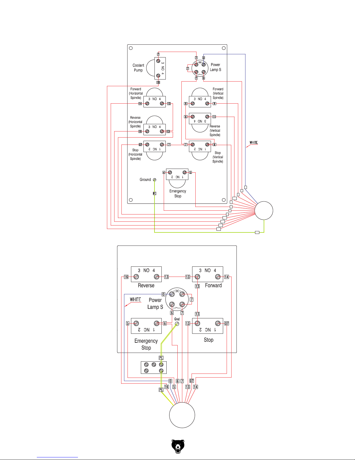
Replaces Page 57
Control Panel Wiring Diagrams
Master
Control
Panel
0
6
9
11
8
5
4
7
13
16
14
18
PE
To Electrical
Cabinet
(Page 55)
Horizontal
Control
Panel
To Electrical
Cabinet
(Page 55)
-2-
G0757 Manual Update (Mfd. Since 9/13)
To M ast e r
Control Panel
(Page 57)
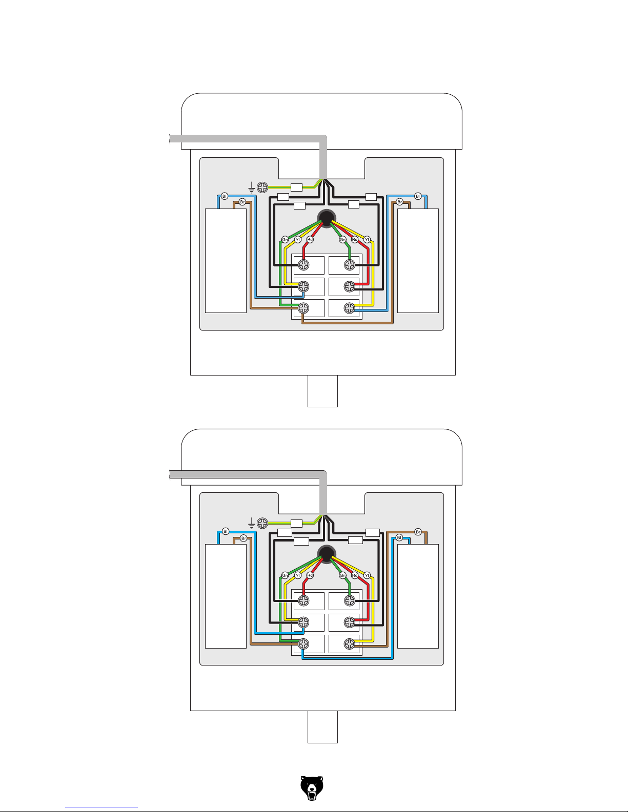
Replaces Page 59
Motor Wiring Diagrams
Vertical Spindle Motor
To Electrical
Cabinet
(Page 55)
Ground
Run
Capacitor
50MFD
450VAC
PE
V2
U1
U1
W2
V1
U2
V1 U2
V2W1
Horizonal Spindle Motor
Start
Capacitor
300MFD
250VAC
Capacitor
450VAC
G0757 Manual Update (Mfd. Since 9/13)
Ground
Run
20MFD
V21
PE
U11
W2
U1
V1 U2
V2
W1
V11
U21
Start
Capacitor
150MFD
250VAC
-3-
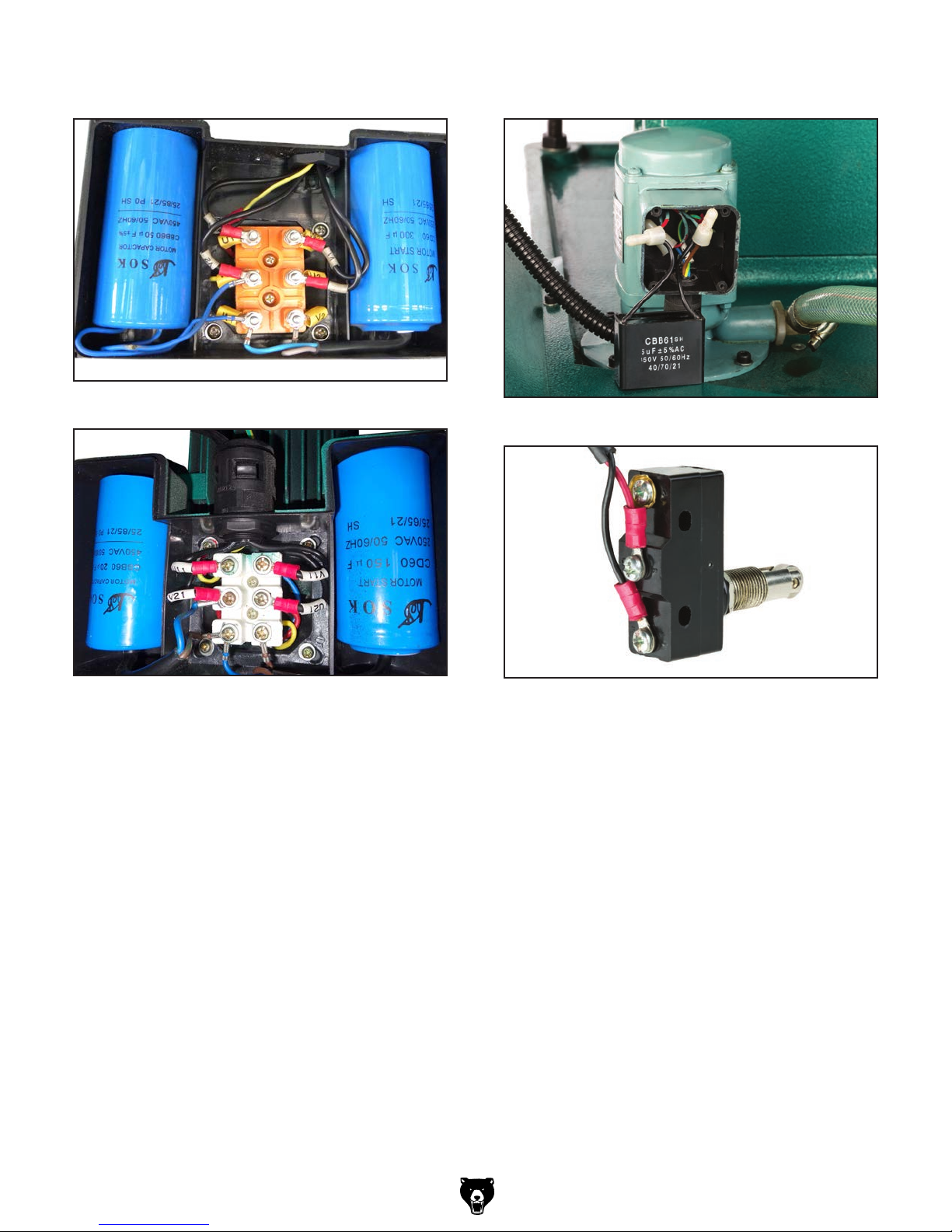
Replaces Page 61
Motor & Other Component Wiring
Figure 75. Vertical spindle motor wiring.
Figure 77. Coolant pump wiring.
Figure 76. Horizontal spindle motor wiring.
Figure 78. Horizontal spindle V-belt cover safety
switch.
-4-
G0757 Manual Update (Mfd. Since 9/13)

MODEL G0757
9" X 39"
HORIZONTAL/VERTICAL
MILLING MACHINE
w/POWER FEED
OWNER'S MANUAL
(For models manufactured since 6/13)
COPYRIGHT © SEPTEMBER, 2013 BY GRIZZLY INDUSTRIAL, INC.
WARNING: NO PORTION OF THIS MANUAL MAY BE REPRODUCED IN ANY SHAPE
OR FORM WITHOUT THE WRITTEN APPROVAL OF GRIZZLY INDUSTRIAL, INC.
#TS15822 PRINTED IN CHINA

This manual provides critical safety instructions on the proper setup,
operation, maintenance, and service of this machine/tool. Save this
document, refer to it often, and use it to instruct other operators.
Failure to read, understand and follow the instructions in this manual
may result in fire or serious personal injury—including amputation,
electrocution, or death.
The owner of this machine/tool is solely responsible for its safe use.
This responsibility includes but is not limited to proper installation in
a safe environment, personnel training and usage authorization,
proper inspection and maintenance, manual availability and comprehension, application of safety devices, cutting/sanding/grinding tool
integrity, and the usage of personal protective equipment.
The manufacturer will not be held liable for injury or property damage
from negligence, improper training, machine modifications or misuse.
Some dust created by power sanding, sawing, grinding, drilling, and
other construction activities contains chemicals known to the State
of California to cause cancer, birth defects or other reproductive
harm. Some examples of these chemicals are:
• Lead from lead-based paints.
• Crystalline silica from bricks, cement and other masonry products.
• Arsenic and chromium from chemically-treated lumber.
Your risk from these exposures varies, depending on how often you
do this type of work. To reduce your exposure to these chemicals:
Work in a well ventilated area, and work with approved safety equipment, such as those dust masks that are specially designed to filter
out microscopic particles.

Table of Contents
INTRODUCTION ............................................... 2
Machine Description ...................................... 2
Contact Info.................................................... 2
Manual Accuracy ........................................... 2
Left Front View Identification ......................... 3
Right Front View Identification ....................... 4
Basic Controls ................................................ 5
Machine Data Sheet ...................................... 7
SECTION 1: SAFETY ..................................... 10
Safety Instructions for Machinery ................ 10
Additional Safety for Milling Machines ......... 12
SECTION 2: POWER SUPPLY ...................... 13
Availability .................................................................13
Full-Load Current Rating ...........................................13
Circuit Requirements for 220V ..................................13
Grounding Instructions ..............................................14
Extension Cords ........................................................14
SECTION 3: SETUP ....................................... 15
Unpacking .................................................... 15
Needed for Setup ......................................... 15
Inventory ...................................................... 16
Cleanup ........................................................ 17
Site Considerations ...................................... 18
Lifting & Placing ........................................... 19
Leveling ........................................................ 20
Anchoring to Floor ....................................... 20
Test Run ...................................................... 21
Mill Test Run .............................................................21
Power Feed Test Run ...............................................22
Spindle Break-In .......................................... 23
Inspections & Adjustments .......................... 23
Downfeed Controls ...................................... 33
Tramming the Mill ........................................ 34
SECTION 5: ACCESSORIES ......................... 36
SECTION 6: MAINTENANCE ......................... 40
Schedule ...................................................... 40
Ongoing .....................................................................40
Before Beginning Operations ....................................40
Daily, After Operations ..............................................40
Cleaning & Protecting .................................. 41
Lubrication ................................................... 41
Ball Oilers ..................................................................42
Vertical Spindle Bearings ..........................................43
Quill Exterior ..............................................................43
Quill Rack & Pinion ...................................................43
Table Leadscrews .....................................................44
Ram Ways .................................................................44
Z-Axis Bevel Gears ...................................................44
X-Axis Power Feed Gears ........................................45
Coolant ......................................................... 46
Hazards .....................................................................46
Checking/Adding Coolant ..........................................46
Changing Coolant .....................................................47
Machine Storage .......................................... 47
SECTION 7: SERVICE ................................... 48
Troubleshooting ........................................... 48
V-Belt Service .............................................. 50
Tensioning Vertical Spindle V-Belts ..........................50
Tensioning Lower Horizontal Spindle V-Belts ...........51
Tensioning Upper Horizontal Spindle V-Belts ...........51
Adjusting Gibs .............................................. 52
Adjusting Leadscrew Backlash .................... 53
SECTION 4: OPERATIONS ........................... 24
Operation Overview ..................................... 24
Table Movement .......................................... 25
Graduated Index Rings .............................................25
Table Locks ...............................................................25
Table Rotation ...........................................................26
Head Tilt....................................................... 26
Ram Movement............................................ 27
Moving Ram Back and Forth ....................................27
Rotating Ram Around Turret .....................................27
Loading/Unloading Tooling .......................... 28
Vertical Spindle .........................................................28
Converting to Horizontal Setup .................................29
Spindle Speed.............................................. 31
Determining Spindle Speed ......................................31
Setting Vertical Spindle Speed .................................31
Setting Horizontal Spindle Speed .............................32
SECTION 8: WIRING ...................................... 54
Wiring Safety Instructions ............................ 54
Electrical Cabinet Wiring Diagram ............... 55
Control Panel Wiring Diagrams ................... 57
Motor Wiring Diagrams ................................ 59
Other Component Wiring Diagrams............. 60
SECTION 9: PARTS ....................................... 62
Column ......................................................... 62
Table ............................................................ 64
Horizontal Spindle & Motor .......................... 66
Headstock .................................................... 68
Electrical Components ................................. 70
Accessories .................................................. 71
Right Side Machine Labels .......................... 72
Left Side Machine Labels ............................ 73
WARRANTY & RETURNS ............................. 77

INTRODUCTION
We are proud to provide a high-quality owner’s
manual with your new machine!
We
instructions, specifications, drawings, and photographs
contained inside. Sometimes we make mistakes,
but
also
means that
you receive
will be slightly different than what is shown in
the manual
If you find this to be the case, and the difference
between the manual and machine leaves you
confused about a procedure
for an updated version. W
manuals
and
www.grizzly.com
Alternatively, you can call our Technical Support
for help. Before calling, please write down the
Manufacture Date
stamped
into the machine ID label (see below). This information helps us determine if updated documentation is available for your machine.
We stand behind our machines. If you have
any questions or need help, use the information
below to contact us. Before contacting, please get
the serial number and manufacture date of your
machine. This will help us help you faster.
We want your feedback on this manual. What did
you like about it? Where could it be improved?
Please take a few minutes to give us feedback.
To reduce your risk of
serious injury, read this
entire manual BEFORE
Machine Description
The Model G0757 Milling Machine has a vertical and horizontal spindle that are designed to
remove material from a metal workpiece secured
to the work table or a mill vise. The cutting tool is
fixed to the rotating spindle and the workpiece is
moved into the cutting tool by lowering the spindle
or moving the table.
Spindle downfeed options are rapid (coarse)
control or slow (fine) control with adjustable autodownfeed controls.
The Model G0757 features high-precision P5
spindle bearings.
The wide range of cutting tools and optional
available equipment combined with the flexible
features of this milling machine makes countless
metalworking operations possible.
Contact Info
Manual Accuracy
made every effort to be exact with the
our policy of continuous improvement
sometimes the machine
.
, check our website
e post current
manual updates for free on our website at
.
and Serial Number
-2-
Grizzly Technical Support
1203 Lycoming Mall Circle
Muncy, PA 17756
Phone: (570) 546-9663
Email: techsupport@grizzly.com
Grizzly Documentation Manager
P.O. Box 2069
Bellingham, WA 98227-2069
Email: manuals@grizzly.com
Manufacture Date
Serial Number
using machine.
Model G0757 (Mfg. Since 6/13)
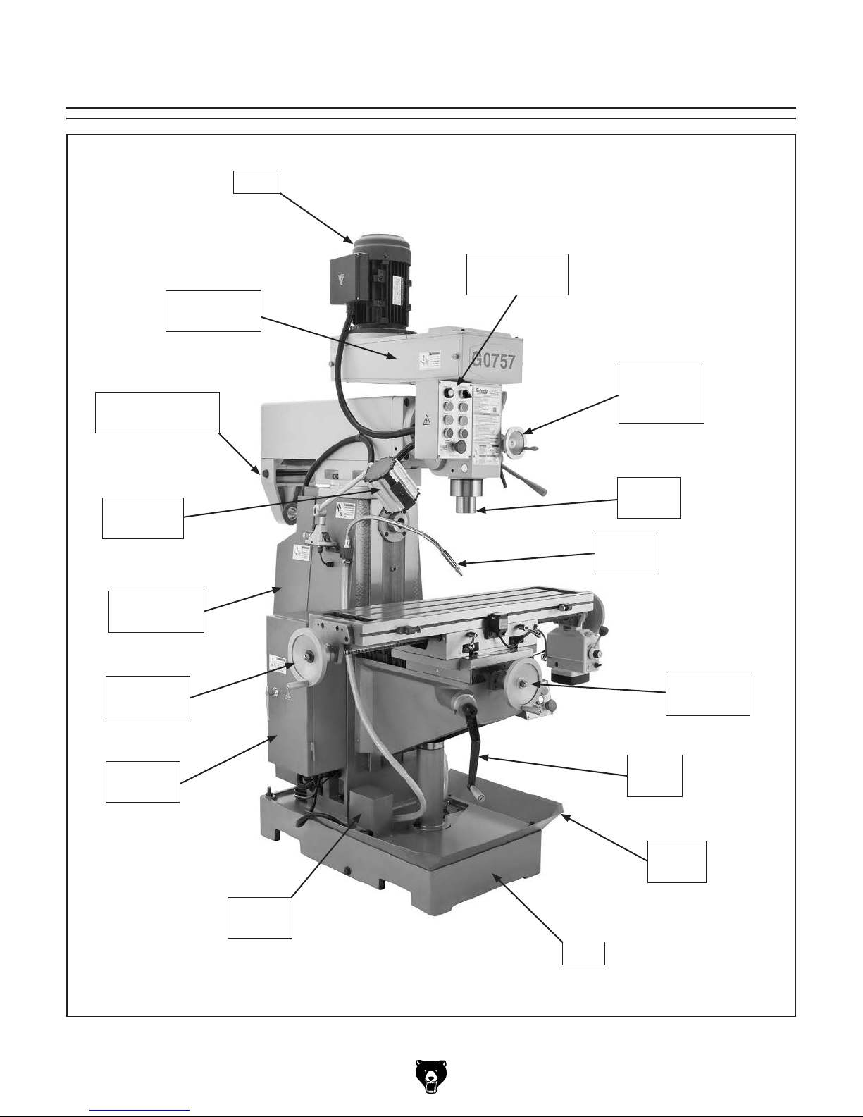
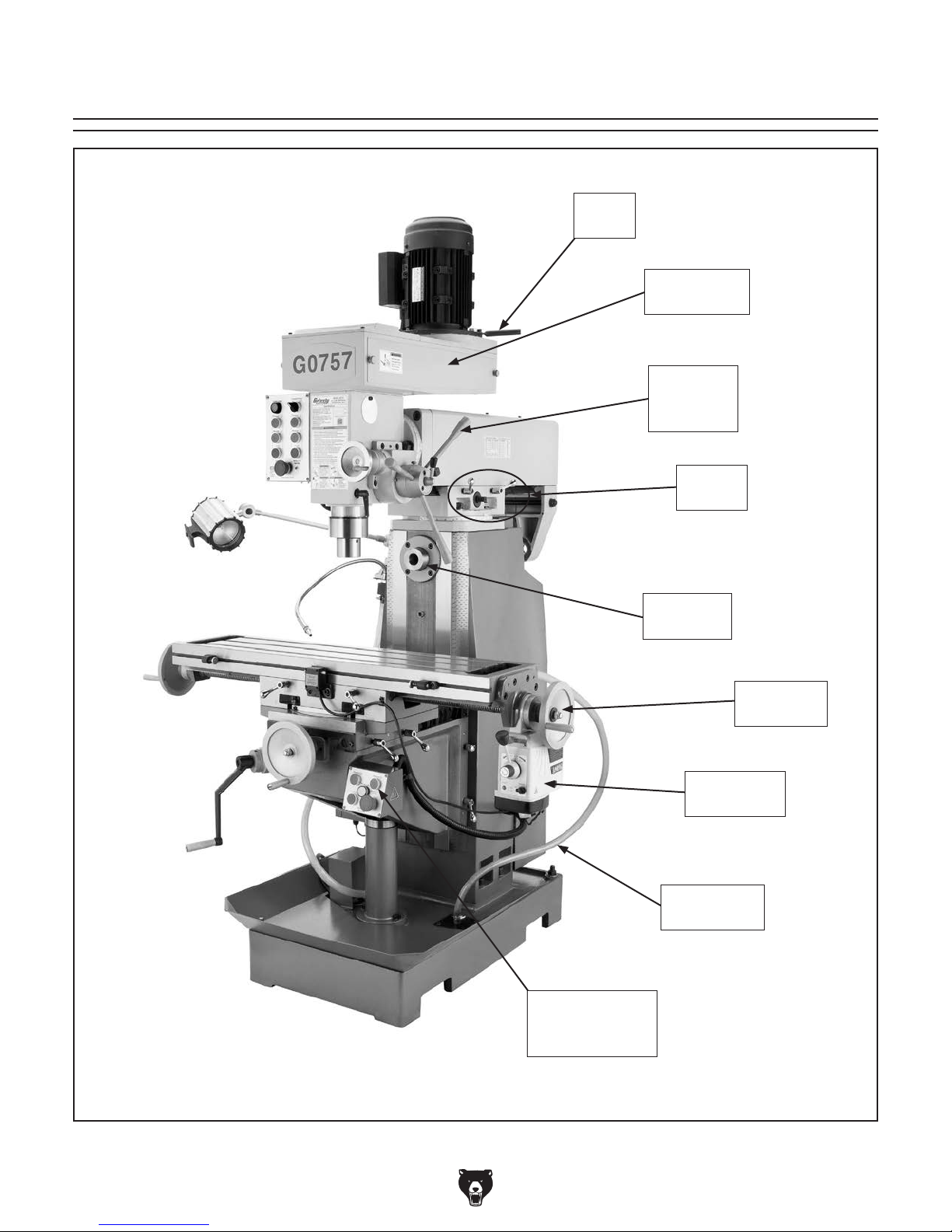
Left Front View Identification
Vertical
V-Belt Cover
Horizontal Arbor
Support
Halogen
Work Light
Motor
Master
Control Panel
Fine
Downfeed
Handwheel
Vertical
Spindle
Coolant
Nozzle
Horizontal
V-Belt Cover
X-Axis
Handwheel
Electrical
Cabinet
Y-Axis
Handwheel
Z-Axis
Crank
Splash
Pan
Coolant
Pump
Base
Model G0757 (Mfg. Since 6/13)
-3-
Right Front View Identification
Motor
Handle
Vertical
V-Belt Cover
Coarse
Downfeed
Lever
Ram
Controls
Horizontal
Spindle Control
Sub-Panel
Horizontal
Spindle
X-Axis
Handwheel
X-Axis
Power Feed
Coolant
Return Hose
-4-
Model G0757 (Mfg. Since 6/13)
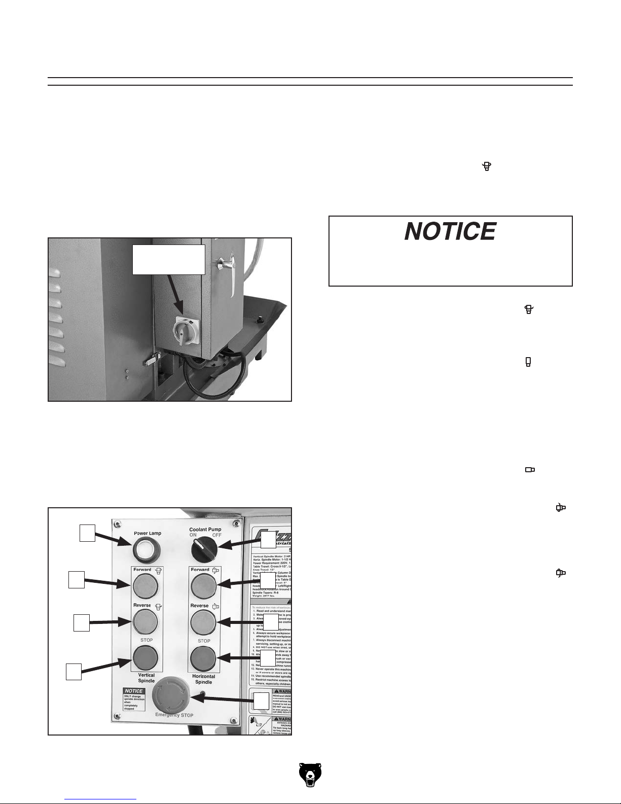
Basic Controls
Refer to Figures 1–3 and the following descrip-
tions to develop an understanding of the basic
controls used to operate the milling machine. This
knowledge will be necessary to safely complete
the Test Run later in this manual.
Additional details for certain controls are also
located in the Operations section.
Master Power Switch
Master
Power Switch
A. Power Lamp Button: When pressed, illu-
minates and enables power to both control
panels. Both Emergency STOP buttons must
be reset first.
B. Forward Button (Vertical
vertical spindle forward rotation (clockwise
looking down on the headstock).
Spindle rotation direction can ONLY be
changed when the spindle is completely
stopped.
C. Reverse Button (Vertical Spindle
vertical spindle reverse rotation (counterclockwise looking down on the headstock).
D. STOP Button (Vertical Spindle
vertical spindle rotation.
Spindle): Starts
): Starts
): Stops
Figure 1. Location of master power switch.
Master Power Switch: Enables power to flow to
the machine when the “l” is visible at the top of
the switch.
Master Control Panel
A
B
C
D
I
H
G
F
E. Emergency STOP Button: Disables power
to both control panels and stops all machine
functions. To reset, twist the button clockwise
until it pops out.
F. STOP Button (Horizontal Spindle
horizontal spindle rotation.
G. Reverse Button (Horizontal Spindle
Starts horizontal spindle reverse rotation
(clockwise as viewed from the front of the
machine).
H. Forward Button (Horizontal Spindle
Starts horizontal spindle forward rotation
(counterclockwise as viewed from the front of
the machine).
I. Coolant Pump Switch: Starts/stops the
coolant pump and the flow of coolant.
): Stops
):
):
Figure 2. Master control panel.
Model G0757 (Mfg. Since 6/13)
E
-5-
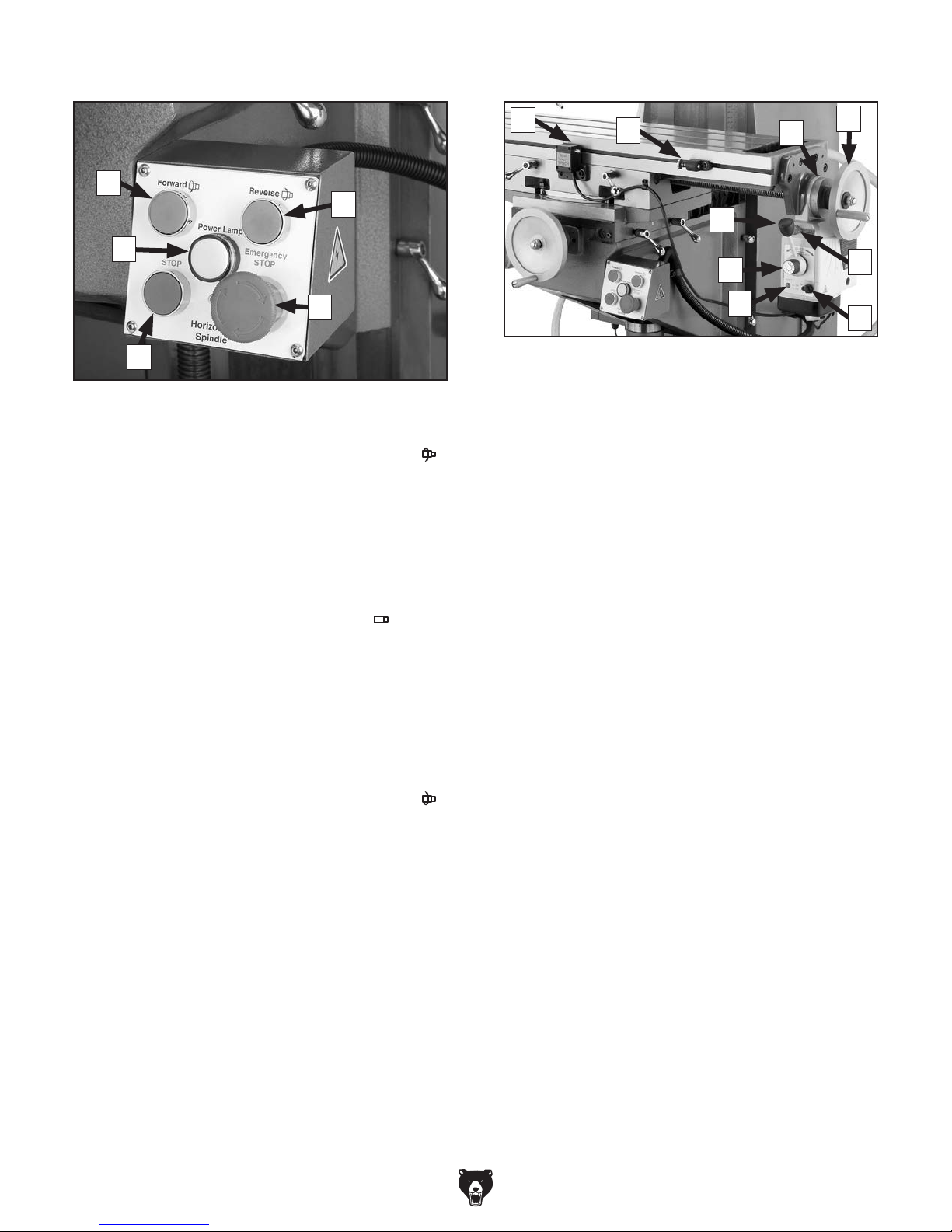
Horizontal Spindle Control Sub-Panel Power Feed
J
N
K
M
L
Figure 3. Horizontal spindle control sub-panel
located on knee.
J. Forward Button (Horizontal Spindle ):
Starts horizontal spindle forward rotation
(counterclockwise as viewed from the front of
the machine).
K. Horizontal Spindle Power Lamp: Illuminates
when power is enabled to the control panels.
A
Figure 4. Power feed components.
A. Limit Switch: Stops powered table move-
ment when either of the side plungers come
in contact with the limit stops.
B. Limit Stop: Limits X-axis table travel (one on
either end of the table).
C. Graduated Dial: Displays X-axis table move-
ment in 0.001" increments, with each revolution equaling 0.200" of travel.
B
E
F
G
C
D
I
H
L. STOP Button (Horizontal Spindle
horizontal spindle rotation.
M. Emergency STOP Button: Only disables
power to all horizontal spindle controls in both
panels, and stops horizontal spindle rotation.
To reset, twist the button clockwise until it
pops out.
N. Reverse Button (Horizontal Spindle
Starts horizontal spindle reverse rotation
(clockwise as viewed from the front of the
machine).
): Stops
):
D. Handwheel: Manually positions the table.
E. Directional Lever: Selects the direction of
table movement. The center position is neutral.
F. Speed Dial: Controls the speed of table
movement. Turning the dial clockwise causes
the table to move faster.
Note: Feed rates for table travel are extreme-
ly difficult to precisely calculate. We recommend that you combine research and experimentation to find the feed rates that best work
for your operations.
G. Reset Button: Resets the internal circuit
breaker if the unit is overloaded and shuts
down.
H. ON/OFF Switch: Enables/disables power to
the unit.
-6-
I. Rapid Traverse Button: Once the direction-
al lever has been activated, causes the table
to travel at full speed while pushed.
Model G0757 (Mfg. Since 6/13)

MACHINE DATA
SHEET
Customer Service #: (570) 546-9663 · To Order Call: (800) 523-4777 · Fax #: (800) 438-5901
MODEL G0757 9" X 39" HORIZONTAL / VERTICAL MILL
WITH POWER FEED
Product Dimensions:
Weight............................................................................................................................................................ 1874 lbs.
Width (side-to-side) x Depth (front-to-back) x Height........................................................ 53-1/2 x 54-7/8 x 81-7/8 in.
Footprint (Length x Width)..................................................................................................................... 35-1/2 x 20 in.
Space Required for Full Range of Movement (Width x Depth).............................................................. 76 x 57-7/8 in.
Shipping Dimensions:
Type.......................................................................................................................................................... Wood Crate
Content........................................................................................................................................................... Machine
Weight............................................................................................................................................................ 2050 lbs.
Length x Width x Height............................................................................................................ 52-3/4 x 45 x 87-1/2 in
Must Ship Upright................................................................................................................................................... Yes
Electrical:
Power Requirement........................................................................................................... 220V, Single-Phase, 60 Hz
Full-Load Current Rating..................................................................................................................................... 13.2A
Minimum Circuit Size.............................................................................................................................................. 20A
Power Cord Included.............................................................................................................................................. Yes
Power Cord Length.......................................................................................................................................... 6-1/2 ft.
Power Cord Gauge......................................................................................................................................... 14 AWG
Plug Included........................................................................................................................................................... No
Recommended Plug Type.......................................................................................................................... NEMA 6-20
Motors:
Coolant Pump
Vertical Spindle
Type............................................................................................................... TEFC Permanent-Split Capacitor
Horsepower................................................................................................................................................. 40W
Phase............................................................................................................................................ Single-Phase
Amps........................................................................................................................................................... 0.2A
Speed................................................................................................................................................ 2800 RPM
Power Transfer ............................................................................................................................... Direct Drive
Bearings........................................................................................................................................ Ball Bearings
Type................................................................................................................. TEFC Capacitor-Start Induction
Horsepower................................................................................................................................................ 3 HP
Phase............................................................................................................................................ Single-Phase
Amps............................................................................................................................................................ 13A
Speed................................................................................................................................................ 1725 RPM
Power Transfer ............................................................................................................................... V-Belt Drive
Bearings........................................................................................................................................ Ball Bearings
Model G0757 (Mfg. Since 6/13)
-7-

Horizontal Spindle
Type................................................................................................................. TEFC Capacitor-Start Induction
Horsepower................................................................................................................................................ 2 HP
Phase............................................................................................................................................ Single-Phase
Amps........................................................................................................................................................... 8.6A
Speed................................................................................................................................................ 1725 RPM
Power Transfer ............................................................................................................................... V-Belt Drive
Bearings.......................................................................................................................................... Ball Bearing
Main Specifications:
Operation Info
Spindle Travel.............................................................................................................................................. 5 in.
Max Distance Spindle to Column........................................................................................................ 26-3/4 in.
Max Distance Spindle to Table............................................................................................................ 14-1/2 in.
Maximum Distance Horizontal Spindle Center to Table...................................................................... 14-1/8 in.
Longitudinal Table Travel (X-Axis)...................................................................................................... 23-1/2 in.
Cross Table Travel (Y-Axis).................................................................................................................. 8-1/2 in.
Vertical Table Travel (Z-Axis).............................................................................................................. 12-1/2 in.
Table Swivel (Left/Right)........................................................................................................................ 45 Deg.
Ram Travel................................................................................................................................................ 11 in.
Turret or Column Swivel (Left /Right)................................................................................................... 180 deg.
Head Tilt (Left/Right).............................................................................................................................. 90 deg.
Drilling Capacity for Cast Iron................................................................................................................ 1-1/8 in.
Drilling Capacity for Steel............................................................................................................................ 1 in.
End Milling Capacity.................................................................................................................................... 1 in.
Face Milling Capacity................................................................................................................................... 4 in.
Table Info
Table Length........................................................................................................................................ 39-3/8 in.
Table Width........................................................................................................................................... 9-1/2 in.
Table Thickness.................................................................................................................................... 2-3/8 in.
Number of T-Slots............................................................................................................................................ 3
T-Slot Size................................................................................................................................................ 5/8 in.
T-Slots Centers............................................................................................................................................ 3 in.
Number of Longitudinal Feeds.............................................................................................................. Variable
X-Axis Table Power Feed Rate................................................................................................... 0 – 11.67 FPM
X/Y-Axis Travel per Handwheel Revolution.......................................................................................... 0.200 in.
Z-Axis Travel per Handwheel Revolution............................................................................................. 0.200 in.
Spindle Info
Spindle Taper............................................................................................................................................... R-8
Number of Vertical Spindle Speeds.................................................................................................................. 9
Range of Vertical Spindle Speeds........................................................................................... 285 – 2300 RPM
Quill Diameter........................................................................................................................................ 3-1/2 in.
Drawbar Thread Size............................................................................................................................. 7/16-20
Drawbar Length............................................................................................................................. 20, 13-3/4 in.
Spindle Bearings.................................................................................................. Tapered Roller Bearings (P5)
Horizontal Spindle Taper.............................................................................................................................. R-8
Number of Horizontal Spindle Speeds............................................................................................................. 8
Range of Horizontal Spindle Speeds......................................................................................... 72 – 1300 RPM
Horizontal Spindle Bearing Type......................................................................... Tapered Roller Bearings (P5)
Construction
Spindle Housing/Quill........................................................................................................... Chromed Cast Iron
Table....................................................................................................................... Precision-Ground Cast Iron
Head.................................................................................................................................................... Cast Iron
Column/Base....................................................................................................................................... Cast Iron
Base..................................................................................................................................................... Cast Iron
Paint Type/Finish.................................................................................................................................... Enamel
-8-
Model G0757 (Mfg. Since 6/13)

Other Specifications:
Country of Origin ................................................................................................................................................ China
Warranty ........................................................................................................................................................... 1 Year
Serial Number Location ..................................................................................................... Machine ID Label on Head
ISO 9001 Factory .................................................................................................................................................. Yes
Features:
Recycling Coolant System
Longitudinal Power Feed
High-Precision P5 Spindle Bearings
Halogen Work Light
Accessories Included:
Arbor Adapter, R-8 to MT#3
Horizontal Arbors w/Spacers, 1-1/4" & 1"
1-13mm Drill Chuck w/Key & Arbor
MT#3 to MT#2 Adapter Sleeve
T-Bolts w/Washers & Nuts
Service Tools & Tool Box
Model G0757 (Mfg. Since 6/13)
-9-

SECTION 1: SAFETY
For Your Own Safety, Read Instruction
Manual Before Operating This Machine
The purpose of safety symbols is to attract your attention to possible hazardous conditions.
This manual uses a series of symbols and signal words intended to convey the level of importance of the safety messages. The progression of symbols is described below. Remember that
safety messages by themselves do not eliminate danger and are not a substitute for proper
accident prevention measures. Always use common sense and good judgment.
Indicates an imminently hazardous situation which, if not avoided,
WILL result in death or serious injury.
Indicates a potentially hazardous situation which, if not avoided,
COULD result in death or serious injury.
Indicates a potentially hazardous situation which, if not avoided,
MAY result in minor or moderate injury. It may also be used to alert
against unsafe practices.
This symbol is used to alert the user to useful information about
NOTICE
proper operation of the machine.
Safety Instructions for Machinery
OWNER’S MANUAL. Read and understand this
owner’s manual BEFORE using machine.
TRAINED OPERATORS ONLY. Untrained operators have a higher risk of being hurt or killed.
Only allow trained/supervised people to use this
machine. When machine is not being used, disconnect power, remove switch keys, or lock-out
machine to prevent unauthorized use—especially
around children. Make workshop kid proof!
DANGEROUS ENVIRONMENTS. Do not use
machinery in areas that are wet, cluttered, or have
poor lighting. Operating machinery in these areas
greatly increases the risk of accidents and injury.
MENTAL ALERTNESS REQUIRED. Full mental
alertness is required for safe operation of machinery. Never operate under the influence of drugs or
alcohol, when tired, or when distracted.
ELECTRICAL EQUIPMENT INJURY RISKS. You
can be shocked, burned, or killed by touching live
electrical components or improperly grounded
machinery. To reduce this risk, only allow qualified
service personnel to do electrical installation or
repair work, and always disconnect power before
accessing or exposing electrical equipment.
DISCONNECT POWER FIRST.
nect machine from power supply BEFORE making
adjustments, changing tooling, or servicing machine.
This prevents an injury risk from unintended startup
or contact with live electrical components.
EYE PROTECTION. Always wear ANSI-approved
safety glasses or a face shield when operating or
observing machinery to reduce the risk of eye
injury or blindness from flying particles. Everyday
eyeglasses are NOT approved safety glasses.
Always discon-
-10 -
Model G0757 (Mfg. Since 6/13)

WEARING PROPER APPAREL. Do not wear
clothing, apparel or jewelry that can become
entangled in moving parts. Always tie back or
cover long hair. Wear non-slip footwear to avoid
accidental slips, which could cause loss of workpiece control.
HAZARDOUS DUST. Dust created while using
machinery may cause cancer, birth defects, or
long-term respiratory damage. Be aware of dust
hazards associated with each workpiece material,
and always wear a NIOSH-approved respirator to
reduce your risk.
HEARING PROTECTION. Always wear hearing protection when operating or observing loud
machinery. Extended exposure to this noise
without hearing protection can cause permanent
hearing loss.
REMOVE ADJUSTING TOOLS. Tools left on
machinery can become dangerous projectiles
upon startup. Never leave chuck keys, wrenches,
or any other tools on machine. Always verify
removal before starting!
USE CORRECT TOOL FOR THE JOB. Only use
this tool for its intended purpose—do not force
it or an attachment to do a job for which it was
not designed. Never make unapproved modifications—modifying tool or using it differently than
intended may result in malfunction or mechanical
failure that can lead to personal injury or death!
AWKWARD POSITIONS. Keep proper footing
and balance at all times when operating machine.
Do not overreach! Avoid awkward hand positions
that make workpiece control difficult or increase
the risk of accidental injury.
CHILDREN & BYSTANDERS. Keep children and
bystanders at a safe distance from the work area.
Stop using machine if they become a distraction.
FORCING MACHINERY. Do not force machine.
It will do the job safer and better at the rate for
which it was designed.
NEVER STAND ON MACHINE. Serious injury
may occur if machine is tipped or if the cutting
tool is unintentionally contacted.
STABLE MACHINE. Unexpected movement during operation greatly increases risk of injury or
loss of control. Before starting, verify machine is
stable and mobile base (if used) is locked.
USE RECOMMENDED ACCESSORIES. Consult
this owner’s manual or the manufacturer for recommended accessories. Using improper accessories will increase the risk of serious injury.
UNATTENDED OPERATION. To reduce the
risk of accidental injury, turn machine OFF and
ensure all moving parts completely stop before
walking away. Never leave machine running
while unattended.
MAINTAIN WITH CARE. Follow all maintenance
instructions and lubrication schedules to keep
machine in good working condition. A machine
that is improperly maintained could malfunction,
leading to serious personal injury or death.
CHECK DAMAGED PARTS. Regularly inspect
machine for any condition that may affect safe
operation. Immediately repair or replace damaged
or mis-adjusted parts before operating machine.
MAINTAIN POWER CORDS. When disconnecting cord-connected machines from power, grab
and pull the plug—NOT the cord. Pulling the cord
may damage the wires inside. Do not handle
cord/plug with wet hands. Avoid cord damage by
keeping it away from heated surfaces, high traffic
areas, harsh chemicals, and wet/damp locations.
GUARDS & COVERS. Guards and covers reduce
accidental contact with moving parts or flying
debris. Make sure they are properly installed,
undamaged, and working correctly.
Model G0757 (Mfg. Since 6/13)
EXPERIENCING DIFFICULTIES. If at any time
you experience difficulties performing the intended operation, stop using the machine! Contact our
Technical Support at (570) 546-9663.
-11-
Additional Safety for Milling Machines
risk of operator injury. If normal safety
precautions are overlooked or ignored,
UNDERSTANDING CONTROLS: The mill is a
complex machine that presents severe cutting or
amputation hazards if used incorrectly. Make sure
you understand the use and operation of all controls before you begin milling.
SAFETY ACCESSORIES: Flying chips or debris
from the cutting operation can cause eye injury
or blindness. Always use safety glasses or a face
shield when milling.
WORK HOLDING: Milling a workpiece that is not
properly secured to the table or in a vise could
cause the workpiece to fly into the operator with
deadly force! Before starting the machine, be
certain the workpiece has been properly clamped
to the table. NEVER hold the workpiece by hand
during operation.
SPINDLE SPEED: To avoid tool or workpiece
breakage that could send flying debris at the
operator and bystanders, use the correct spindle
speed for the operation. Allow the spindle to gain
full speed before beginning the cut.
SPINDLE DIRECTION CHANGE: Changing
spindle rotation direction while it is spinning
could lead to impact injury from broken tool or
workpiece debris, and workpiece or machine
damage. ALWAYS make sure the spindle is at a
complete stop before changing spindle direction.
STOPPING SPINDLE: To reduce the risk of
hand injuries or entanglement hazards, DO NOT
attempt to stop the spindle with your hand or a
tool. Allow the spindle to stop on its own or use
the spindle brake.
CHIP CLEANUP: Chips from the operation are
sharp and hot, which can cause burns or cuts.
Using compressed air to clear chips could cause
them to fly into your eyes, and may drive them
deep into the working parts of the machine. Use
a brush or vacuum to clear away chips and debris
from machine or workpiece and NEVER clear
chips while spindle is turning.
MACHINE CARE & MAINTENANCE: Operating
the mill with excessively worn or damaged machine
parts increases risk of machine or workpiece
breakage which could eject hazardous debris at
the operator. To reduce this risk, maintain the mill
in proper working condition by ALWAYS promptly
performing routine inspections and maintenance.
CUTTING TOOL USAGE: Cutting tools have
very sharp leading edges—handle them with
care! Using cutting tools that are in good condition helps to ensure quality milling results and
reduces risk of personal injury from broken tool
debris. Inspect cutting tools for sharpness, chips,
or cracks before each use, and ALWAYS make
sure cutting tools are firmly held in place before
starting the machine.
Like all machinery there is potential danger
when operating this machine. Accidents
are frequently caused by lack of familiarity
or failure to pay attention. Use this machine
with respect and caution to decrease the
serious personal injury may occur.
-12-
No list of safety guidelines can be complete. Every shop environment is different.
Always consider safety first, as it applies
to your individual working conditions. Use
this and other machinery with caution and
respect. Failure to do so could result in
serious personal injury, damage to equipment, or poor work results.
Model G0757 (Mfg. Since 6/13)

SECTION 2: POWER SUPPLY
Before installing the machine, consider the availability and proximity of the required power supply
circuit. If an existing circuit does not meet the
requirements for this machine, a new circuit must
be installed. To minimize the risk of electrocution,
fire, or equipment damage, installation work and
electrical wiring must be done by an electrican or
qualified service personnel in accordance with all
applicable codes and standards.
Electrocution, fire, or
equipment damage may
occur if machine is not
correctly grounded and
connected to the power
The full-load current rating is the amperage a
machine draws at 100% of the rated output power.
On machines with multiple motors, this is the
amperage drawn by the largest motor or sum of all
motors and electrical devices that might operate
at one time during normal operations.
The full-load current is not the maximum amount
of amps that the machine will draw. If the machine
is overloaded, it will draw additional amps beyond
the full-load rating.
If the machine is overloaded for a sufficient length
of time, damage, overheating, or fire may result—
especially if connected to an undersized circuit.
To reduce the risk of these hazards, avoid overloading the machine during operation and make
sure it is connected to a power supply circuit that
meets the requirements in the following section.
This machine is prewired to operate on a 220V
power supply circuit that has a verified ground and
meets the following requirements:
For your own safety and protection of
Note: The circuit requirements listed in this manual apply to a dedicated circuit—where only one
machine will be running at a time. If this machine
will be connected to a shared circuit where multiple machines will be running at the same time,
consult a qualified electrician to ensure that the
circuit is properly sized for safe operation.
A power supply circuit includes all electrical
equipment between the breaker box or fuse panel
in the building and the machine. The power supply circuit used for this machine must be sized to
safely handle the full-load current drawn from the
machine for an extended period of time. (If this
machine is connected to a circuit protected by
fuses, use a time delay fuse marked D.)
Availability
supply.
Full-Load Current Rating
Circuit Requirements for 220V
Nominal Voltage .............................. 220V/240V
Cycle .......................................................... 60 Hz
Phase .................................................... 1-Phase
Power Supply Circuit ......................... 20 Amps
Plug/Receptacle ............................. NEMA 6-20
Full-Load Current Rating at 220V .. 13.2 Amps
Model G0757 (Mfg. Since 6/13)
property, consult an electrician if you are
unsure about wiring practices or electrical
codes in your area.
-13-
We do not recommend using an extension cord
with this machine.
cord, only use it if absolutely necessary and only
on a temporary basis.
Extension cords cause voltage drop, which may
damage electrical components and shorten motor
life. Voltage drop increases as the extension cord
size gets longer and the gauge size gets smaller
(higher gauge numbers indicate smaller sizes).
Any extension cord used with this machine must
contain a ground wire, match the required plug
and receptacle, and meet the following requirements:
Grounding Instructions
This machine MUST be grounded. In the event
of certain malfunctions or breakdowns, grounding
reduces the risk of electric shock by providing a
path of least resistance for electric current.
Improper connection of the equipment-grounding
wire can result in a risk of electric shock. The
wire with green insulation (with or without yellow
stripes) is the equipment-grounding wire. If repair
or replacement of the power cord or plug is necessary, do not connect the equipment-grounding
wire to a live (current carrying) terminal.
Check with a qualified electrician or service personnel if you do not understand these grounding
requirements, or if you are in doubt about whether
the tool is properly grounded. If you ever notice
that a cord or plug is damaged or worn, disconnect it from power, and immediately replace it with
a new one.
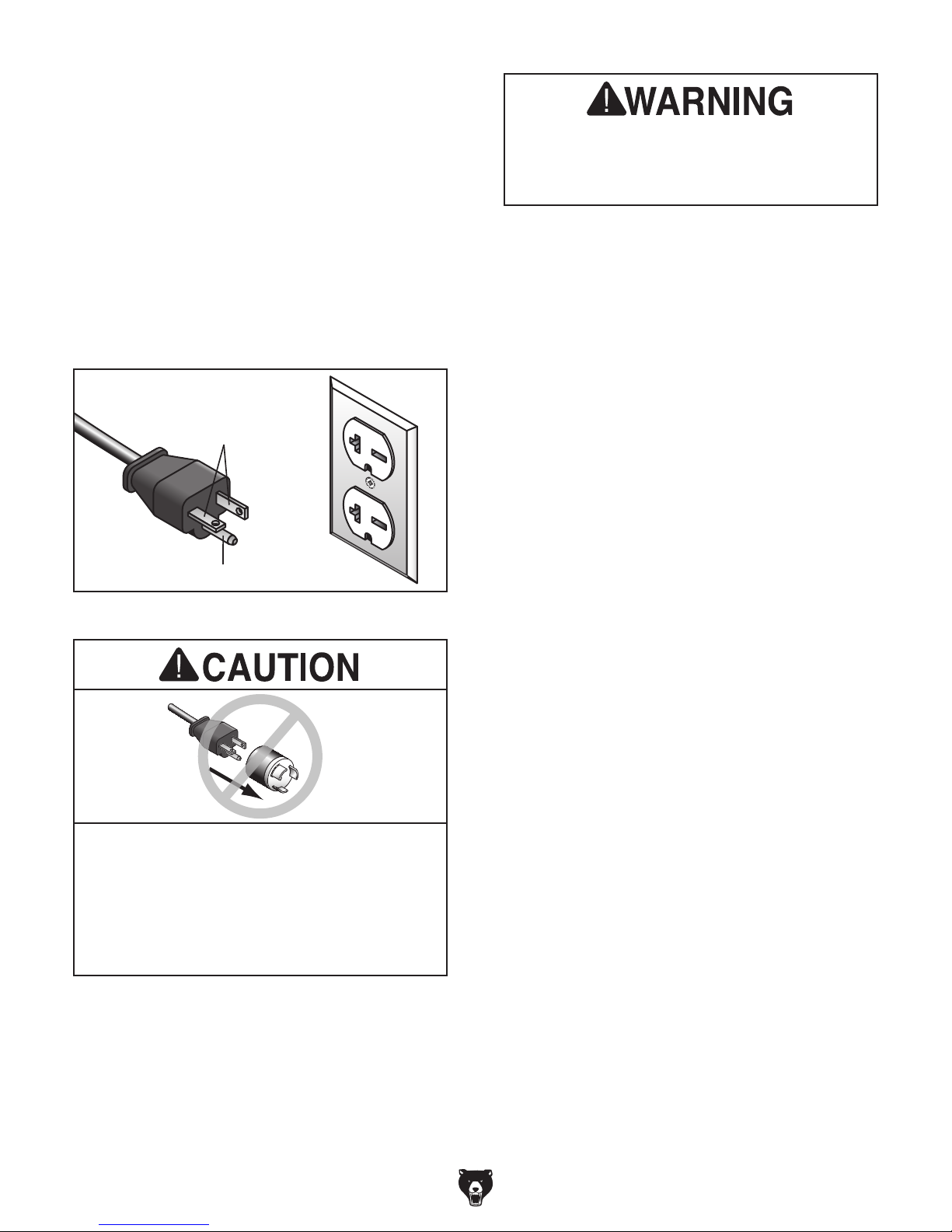
The power cord and plug specified under “Circuit
Requirements for 220V”
has an equipment-grounding wire and a grounding prong. The plug must only be inserted into
a matching receptacle (outlet) that is properly
installed and grounded in accordance with all
local codes and ordinances (see figure below).
No adapter should be used with the
required plug. If the plug does not fit the
available receptacle, or the machine must
on the previous page
GROUNDED
6-20 RECEPTACLE
Current Carrying Prongs
6-20 PLUG
Serious injury could occur if you connect
the machine to power before completing the
setup process. DO NOT connect to power
until instructed later in this manual.
Grounding Prong
Figure 5. Typical 6-20 plug and receptacle.
be reconnected for use on a different type
of circuit, the reconnection must be made
by a qualified electrician and comply with all
local codes and ordinances.
-14-
Extension Cords
If you must use an extension
Minimum Gauge Size ...........................12 AWG
Maximum Length (Shorter is Better).......50 ft.
Model G0757 (Mfg. Since 6/13)
SECTION 3: SETUP
Your machine was carefully packaged for safe
transportation. Remove the packaging materials
from around your machine and inspect it. If you
discover any damage, please call us immediately
at (570) 546-9663
Save the containers and all packing materials for
possible inspection by the carrier or its agent.
Otherwise, filing a freight claim can be difficult.
When you are completely satisfied with the condition of your shipment, inventory the contents.
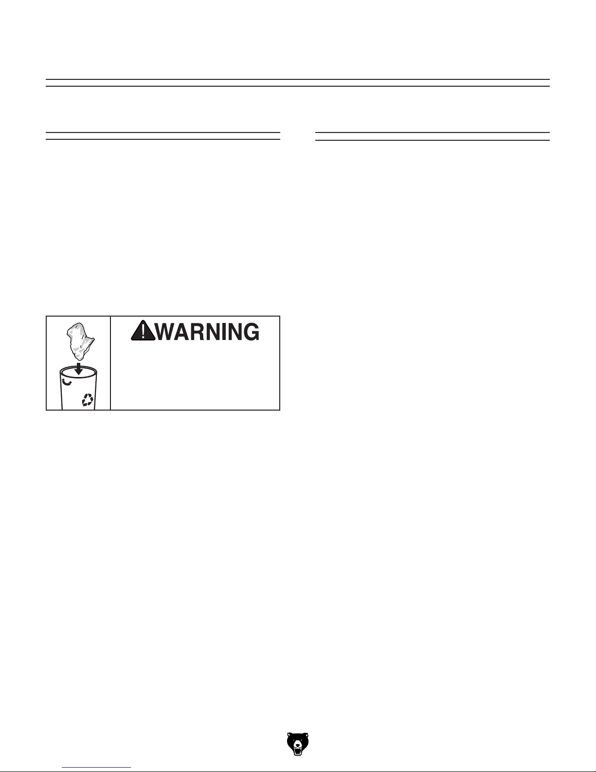
Keep children and pets away
from plastic bags or packing
materials shipped with this
Unpacking
for advice.
SUFFOCATION HAZARD!
machine. Discard immediately.
Needed for Setup
The following are needed to complete the setup
process, but are not included with your machine.
For Lifting (Page 19)
• A forklift or other power lifting device rated for
50% more than the weight of the machine.
• Two lifting straps and a chain with a safety
hook, each rated for 50% more than the
weight of the machine.
• At least two other persons to help with the
operation.
• Safety glasses for each person.
For Cleanup
• Cotton disposable rags.
• Cleaner/degreaser (see Page 17).
For Power Connection
• We recommend a qualified electrician to
ensure a safe and code-compliant connection to the power source (refer to Page 13 for
details).
Model G0757 (Mfg. Since 6/13)
-15-
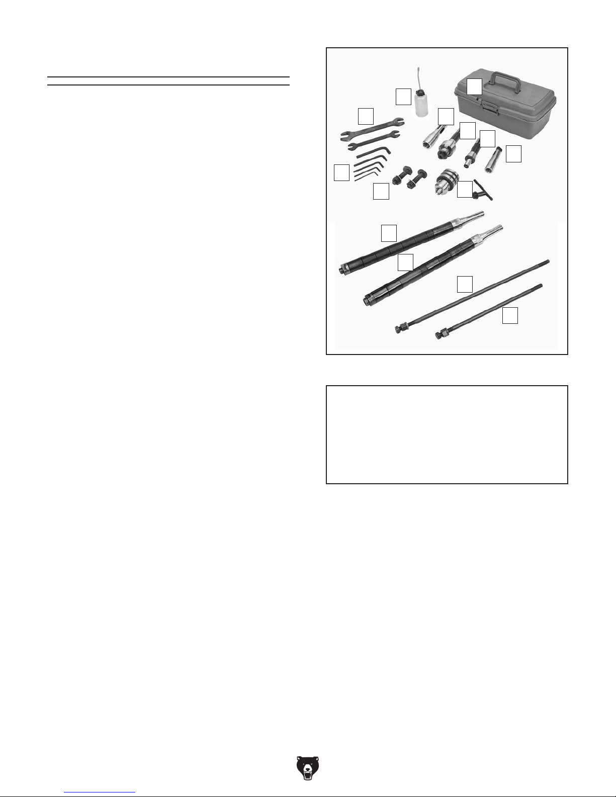
Inventory
The following is a list of items shipped with your
machine. Before beginning setup, lay these items
out and inventory them.
If any non-proprietary parts are missing (e.g. a
nut or a washer), we will gladly replace them; or
for the sake of expediency, replacements can be
obtained at your local hardware store.
C
B
Small Item Inventory (see Figure 6): Qty
A. Open-End Wrenches 17/19, 22/24mm ..1 Ea
B. Bottle for Oil ............................................... 1
C. Toolbox ....................................................... 1
D. Spindle Sleeve R-8–MT#3 ......................... 1
E. End Mill Arbor R-8–1" ................................. 1
F. Drill Chuck Arbor R-8–B16 ......................... 1
G. Spindle Sleeve MT#3–MT#2 ...................... 1
H. Drill Chuck B16, 1–13mm w/Chuck Key ..... 1
I. T-Bolts M14-2 x 60 ..................................... 2
— Flat Washers 14mm ................................ 2
— Hex Nuts M14-2 ...................................... 2
J. Hex Wrenches 8, 6, 5, 4, 3mm .............1 Ea
K. Horizontal Arbor 1
L. Horizontal Arbor 1" Dia. w/Spacers ............ 1
M. Vertical Spindle Drawbar
N. Horizontal Spindle Drawbar
7
⁄16 –20 x 13 3⁄4" ............................................. 1
1
⁄4" Dia. w/Spacers ......... 1
7
⁄16 –20 x 20" ....... 1
A
J
I
K
L
Figure 6. Small item inventory.
D
E
F
G
H
M
N
NOTICE
If you cannot find an item on this list, carefully check around/inside the machine and
packaging materials. Often, these items get
lost in packaging materials while unpacking or they are pre-installed at the factory.
-16 -
Model G0757 (Mfg. Since 6/13)
The unpainted surfaces of your machine are
coated with a heavy-duty rust preventative that
prevents corrosion during shipment and storage.
This rust preventative works extremely well, but it
will take a little time to clean.
Be patient and do a thorough job cleaning your
machine. The time you spend doing this now will
give you a better appreciation for the proper care
of your machine's unpainted surfaces.
There are many ways to remove this rust preventative, but the following steps work well in a wide
variety of situations. Always follow the manufacturer’s instructions with any cleaning product you
use and make sure you work in a well-ventilated
area to minimize exposure to toxic fumes.
Before cleaning, gather the following:
• Disposable rags
• Cleaner/degreaser (WD•40 works well)
• Safety glasses & disposable gloves
• Plastic paint scraper (optional)
Basic steps for removing rust preventative:
1.
2.
3.
4.
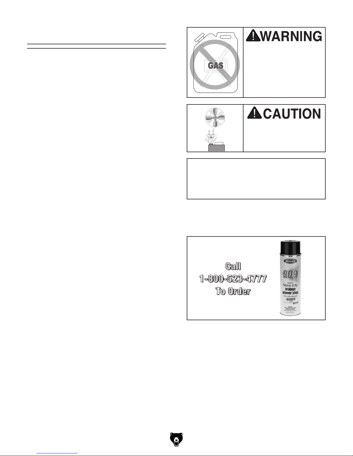
Many cleaning solvents
work in a well-ventilated
Avoid chlorine-based solvents, such as
Cleanup
Gasoline and petroleum
products have low flash
points and can explode
or cause fire if used to
clean machinery. A v oid
using these products
to clean machinery.
Put on safety glasses.
Coat the rust preventative with a liberal
amount of cleaner/degreaser, then let it soak
for 5–10 minutes.
Wipe off the surfaces. If your cleaner/degreas-
er is effective, the rust preventative will wipe
off easily. If you have a plastic paint scraper,
scrape off as much as you can first, then wipe
off the rest with the rag.
are toxic if inhaled. Only
area.
NOTICE
acetone or brake parts cleaner, that may
damage painted surfaces.
T23692—Orange Power Degreaser
A great product for removing the waxy shipping
grease from your machine during clean up.
Figure 7. T23692 Orange Power Degreaser.
Repeat Steps 2–3 as necessary until clean,
then coat all unpainted surfaces with a quality
metal protectant to prevent rust.
Model G0757 (Mfg. Since 6/13)
-17-
Site Considerations
Weight Load
Physical Environment
Place this machine near an existing power source.
Shadows, glare, or strobe effects that may distract
Refer to the Machine Data Sheet for the weight
of your machine. Make sure that the surface upon
which the machine is placed will bear the weight
of the machine, additional equipment that may be
installed on the machine, and the heaviest workpiece that will be used. Additionally, consider the
weight of the operator and any dynamic loading
that may occur when operating the machine.
Space Allocation
Consider the largest size of workpiece that will
be processed through this machine and provide
enough space around the machine for adequate
operator material handling or the installation of
auxiliary equipment. With permanent installations,
leave enough space around the machine to open
or remove doors/covers as required by the maintenance and service described in this manual.
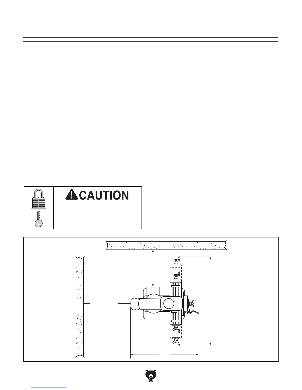
See below for required space allocation.
Children or untrained people
may be seriously injured by
this machine. Only install in an
access restricted location.
The physical environment where the machine is
operated is important for safe operation and longevity of machine components. For best results,
operate this machine in a dry environment that is
free from excessive moisture, hazardous chemicals, airborne abrasives, or extreme conditions.
Extreme conditions for this type of machinery are
generally those where the ambient temperature
range exceeds 41°–104°F; the relative humidity
range exceeds 20–95% (non-condensing); or the
environment is subject to vibration, shocks, or
bumps.
Electrical Installation
Make sure all power cords are protected from
traffic, material handling, moisture, chemicals,
or other hazards. Make sure to leave access to
a means of disconnecting the power source or
engaging a lockout/tagout device, if required.
Lighting
Lighting around the machine must be adequate
enough that operations can be performed safely.
or impede the operator must be eliminated.
30"
Minimum
Wall
Clearance
-18-
Wall
30"
Minimum
Clearance
56"
Figure 8. Minimum working clearances.
763⁄4"
Model G0757 (Mfg. Since 6/13)
Lifting & Placing
get help from other people
HEAVY LIFT!
Straining or crushing injury
may occur from improperly
lifting machine or some of
its parts. To reduce this risk,
and use a forklift (or other
lifting equipment) rated for
weight of this machine.
Power lifting equipment rated for at least 50%
more than the weight of the machine and at least
two other people are required to lift and place the
mill.
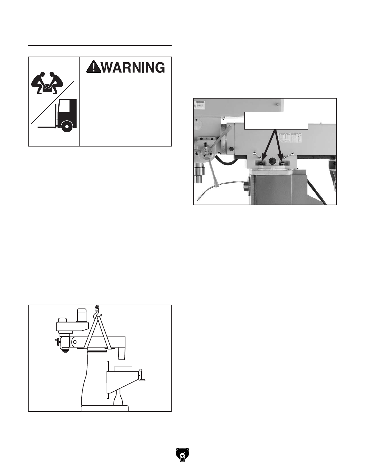
To lift and move the mill:
Note: After repositioning ram and headstock,
make sure they are locked in place to prevent
unexpected movement while lifting.
3. Torque the four turret lock bolts (two on each
side of ram, as shown in Figure 10) to 47 ft/
lbs. This will help keep ram from unexpectedly moving from force of lifting straps.
Turret Locking Bolts
(2 of 4)
1. Remove crate from shipping pallet then,
while still on pallet, move machine to installation location.
2. Rotate ram 180° so headstock faces backwards (see Figure 9), then rotate head
upright.
Refer to Head Tilt on Page 26 and Ram
Movement on Page 27 for detailed instructions to help with this step.
Figure 10. Locations of turret locking bolts.
4. Place lifting straps under ram and connect to
a safety hook, as illustrated in Figure 9.
Note: Place protective material between
straps and mill to protect ram and ways, and
to prevent cutting lifting straps.
5. Unbolt mill from shipping pallet.
6. With other people steadying the load to keep
it from swaying, lift machine a couple of
inches.
— If mill tips to one side, lower it to the pallet
and adjust ram or table to balance load.
Make sure to retighten lock levers and
bolts before lifting mill again.
— If mill lifts evenly, remove shipping pallet
and lower mill.
Figure 9. Using lifting straps to lift and move
mill.
Model G0757 (Mfg. Since 6/13)
-19 -

Anchoring machinery to the floor prevents tipping
or shifting and reduces vibration that may occur
during operation, resulting in a machine that runs
slightly quieter and feels more solid.
If the machine will be installed in a commercial or
workplace setting, or if it is permanently connected (hardwired) to the power supply, local codes
may require that it be anchored to the floor.
If not required by any local codes, fastening the
machine to the floor is an optional step. If you
choose not to do this with your machine, we recommend placing it on machine mounts, as these
provide an easy method for leveling and they have
vibration-absorbing pads.
Lag shield anchors with lag screws (see below)
are a popular way to anchor machinery to a concrete floor, because the anchors sit flush with the
floor surface, making it easy to unbolt and move
the machine later, if needed. However, anytime
local codes apply, you MUST follow the anchoring
methodology specified by the code.
Leveling
Leveling machinery helps precision components,
such as dovetail ways, remain straight and flat
during the lifespan of the machine. Components
on an unleveled machine may slowly twist due to
the dynamic loads placed on the machine during
operation.
For best results, use a precision level that is at
least 12" long and sensitive enough to show a
distinct movement when a 0.003" shim (approximately the thickness of one sheet of standard
newspaper) is placed under one end of the level.
See Figure 11 for an example of a high precision
level available from Grizzly.
Anchoring to Floor
Anchoring to Concrete Floors
Figure 11. Example of a precision level
(Model H2683 shown).
-20-
Lag Screw
Flat Washer
Machine Base
Concrete
Figure 12. Popular method for anchoring
machinery to a concrete floor.
Model G0757 (Mfg. Since 6/13)
Lag Shield Anchor
Drilled Hole
 Loading...