

Page 1
MODEL G0756
INDUSTRIAL DRILL PRESS
OWNER'S MANUAL
(For models manufactured since 03/13)
COPYRIGHT © MAY, 2013 BY GRIZZLY INDUSTRIAL, INC.,
WARNING: NO PORTION OF THIS MANUAL MAY BE REPRODUCED IN ANY SHAPE
OR FORM WITHOUT THE WRITTEN APPROVAL OF GRIZZLY INDUSTRIAL, INC.
#DM15670 PRINTED IN CHINA
Page 2

This manual provides critical safety instructions on the proper setup,
operation, maintenance, and service of this machine/tool. Save this
document, refer to it often, and use it to instruct other operators.
Failure to read, understand and follow the instructions in this manual
may result in fire or serious personal injury—including amputation,
electrocution, or death.
The owner of this machine/tool is solely responsible for its safe use.
This responsibility includes but is not limited to proper installation in
a safe environment, personnel training and usage authorization,
proper inspection and maintenance, manual availability and comprehension, application of safety devices, cutting/sanding/grinding tool
integrity, and the usage of personal protective equipment.
The manufacturer will not be held liable for injury or property damage
from negligence, improper training, machine modifications or misuse.
Some dust created by power sanding, sawing, grinding, drilling, and
other construction activities contains chemicals known to the State
of California to cause cancer, birth defects or other reproductive
harm. Some examples of these chemicals are:
• Lead from lead-based paints.
• Crystalline silica from bricks, cement and other masonry products.
• Arsenic and chromium from chemically-treated lumber.
Your risk from these exposures varies, depending on how often you
do this type of work. To reduce your exposure to these chemicals:
Work in a well ventilated area, and work with approved safety equipment, such as those dust masks that are specially designed to filter
out microscopic particles.
Page 3

Table of Contents
INTRODUCTION ............................................... 2
Machine Description ...................................... 2
Contact Info.................................................... 2
Manual Accuracy ........................................... 2
Identification ................................................... 3
Control Panel ................................................. 4
Machine Data Sheet ...................................... 5
SECTION 1: SAFETY ....................................... 7
Safety Instructions for Machinery .................. 7
Safety for Drill Presses .................................. 9
SECTION 2: POWER SUPPLY ...................... 10
Availability ......................................................... 10
Full-Load Current Rating .................................. 10
Circuit Requirements for 220V .......................... 10
Grounding Instructions ...................................... 11
Extension Cords ................................................ 11
SECTION 3: SETUP ....................................... 12
Unpacking .................................................... 12
Needed for Setup ......................................... 12
Inventory ...................................................... 12
Cleanup ........................................................ 13
Site Considerations ...................................... 14
Lifting & Placing ........................................... 15
Anchoring to Floor ....................................... 15
Anchoring to Concrete Floors ........................... 15
Arbor/Chuck Assembly ................................ 16
Initial Lubrication .......................................... 16
Power Connection........................................ 17
Test Run ...................................................... 18
Coolant System............................................ 20
Spindle Break-In .......................................... 21
SECTION 4: OPERATIONS ........................... 22
Operations Overview ................................... 22
Tooling Installation & Removal .................... 22
Installing Tapered Tooling ................................ 23
Removing Tooling with Automatic Drift ............. 23
Removing Tooling Manually ............................. 23
Depth Stop ................................................... 24
Table Positioning ......................................... 24
Raising/Lowering Table ....................................24
Rotating Table ................................................... 24
Selecting Spindle RPM ................................ 25
Drilling Mode ................................................ 26
Automatic Power Downfeed ........................ 27
Tapping Mode .............................................. 28
Coolant System............................................ 28
SECTION 6: MAINTENANCE ......................... 32
Schedule ...................................................... 32
Ongoing ............................................................32
Daily, After Operations ...................................... 32
Annually ............................................................ 32
Cleaning and Protecting .............................. 32
Lubrication ................................................... 33
Headstock Lubrication ......................................33
Ball Oilers .......................................................... 34
Changing Coolant ........................................ 34
SECTION 7: SERVICE ................................... 35
Troubleshooting ........................................... 35
Motor & Electrical .............................................. 35
Drill Press Operations ....................................... 36
Replacing Lamp Bulb ................................... 37
Torque Limiter .............................................. 37
SECTION 8: WIRING ...................................... 38
Wiring Safety Instructions ............................ 38
Wiring Overview ........................................... 39
Component Location Index .......................... 39
Power Connection Wiring ............................ 40
Electric Clutch Wiring ................................... 40
Motor & Pump Wiring ................................. 41
Control Panel ............................................... 42
Control Panel & Limit Switches ................... 43
Electrical Panel Wiring ................................. 44
Electrical Wiring Panel Photo ...................... 45
SECTION 9: PARTS ....................................... 46
Table Support & Coolant Breakdown .......... 46
Gearbox Breakdown .................................... 48
Gearbox Breakdown 2 ................................. 49
Spindle Feed Breakdown ............................. 51
Headstock Breakdown ................................. 53
Headstock Breakdown 2 .............................. 54
Electrical Parts Breakdown .......................... 56
Labels & Cosmetics ..................................... 58
WARRANTY & RETURNS ............................. 61
SECTION 5: ACCESSORIES ......................... 29
Page 4
INTRODUCTION
We are proud to provide a high-quality owner’s
manual with your new machine!
We
instructions, specifications, drawings, and photographs
contained inside. Sometimes we make mistakes,
but
also
means that
you receive
will be slightly different than what is shown in
the manual
If you find this to be the case, and the difference
between the manual and machine leaves you
confused about a procedure
for an updated version. W
manuals
and
www.grizzly.com
Alternatively, you can call our Technical Support
for help. Before calling, please write down the
Manufacture Date
stamped
into the machine ID label (see below). This information helps us determine if updated documentation is available for your machine.
We stand behind our machines. If you have
any questions or need help, use the information
below to contact us. Before contacting, please get
the serial number and manufacture date of your
machine. This will help us help you faster.
We want your feedback on this manual. What did
you like about it? Where could it be improved?
Please take a few minutes to give us feedback.
Machine Description
We are proud to offer the Model G0756 18-speed
Heavy-Duty Drill Press. When used according to
the guidelines set forth in this manual, you can
expect years of trouble-free, enjoyable operation
and proof of Grizzly’s commitment to customer
satisfaction.
This drill press features power tapping with an
electronic clutch and activation buttons on the
downfeed handles. Spindle speed is adjustable
through the use of the levers above the main
control panel. The pump-controlled coolant system helps provide optimum working results and
extended longevity of tooling.
Contact Info
Manual Accuracy
made every effort to be exact with the
our policy of continuous improvement
sometimes the machine
.
, check our website
e post current
manual updates for free on our website at
.
and Serial Number
Grizzly Technical Support
1203 Lycoming Mall Circle
Muncy, PA 17756
Phone: (570) 546-9663
Email: techsupport@grizzly.com
Grizzly Documentation Manager
P.O. Box 2069
Bellingham, WA 98227-2069
Email: manuals@grizzly.com
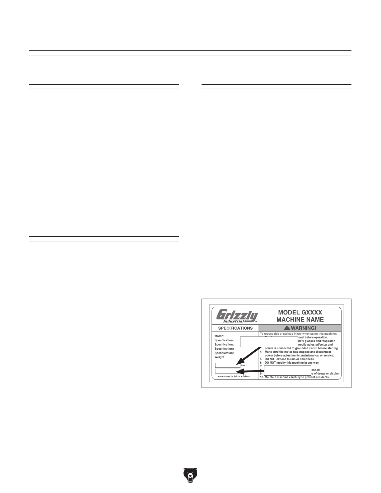
Manufacture Date
Serial Number
-2-
Model G0756 (Mfg. Since 2/13)
Page 5
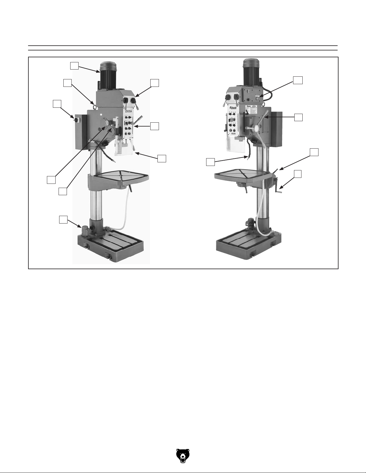
Identification
C
B D
A
I
H
G
K
L
E
M
F
J
N
A. Main Power Switch
B. Lifting Eye Bolt
C. Motor
D. Speed Control Levers
E. Control Panel (see Page 4 for details)
F. Chip Guard
G. Coolant Pump
Model G0756 (Mfg. Since 2/13)
H. Automatic Drift
I. Automatic Downfeed Adjustment Knob
J. Coolant Nozzle
K. Oil Site Glass
L. Coarse Downfeed Handles
M. Table Lock Handles
N. Table Height Adjustment Crank
-3-
Page 6
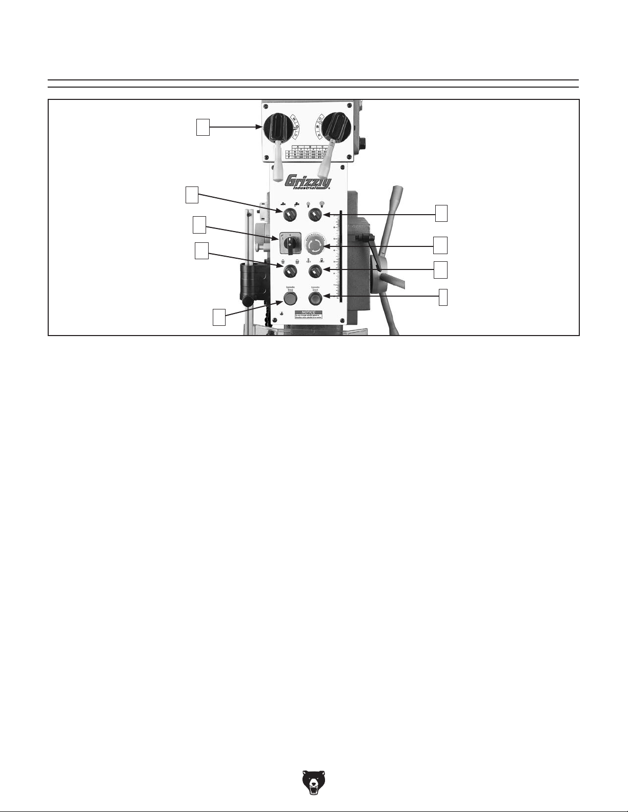
Control Panel
A
B
F
C
D
E
Figure 1. Control panel
A. Spindle Speed Levers: Used to get spindle
speed at available RPMs.
B. Coolant Pump Switch: Turns pump on,
sending coolant to nozzle
C. High/Low Spindle Speed Range Switch:
Selects high/low range for spindle speed.
D. Spindle Rotation Switch: Controls direction.
E. Spindle Stop Button: Stops all work.
G
H
I
F. Working Lamp Switch: Turns work light on
or off.
G. EMERGENCY STOP Button: Immediately
cuts power to motor and control panel when
pressed. Remains depressed until button is
reset by twisting clockwise.
H. Drilling/Tapping Switch: Selects between
drilling and tapping modes.
I. Spindle Start Button: Starts machine when
Master Power Switch has already been
turned to the ON position and the high/low
spindle speed range switch is turned to 1 or
2.
-4-
Model G0756 (Mfg. Since 2/13)
Page 7

Machine Data Sheet
MACHINE DATA
SHEET
Customer Service #: (570) 546-9663 · To Order Call: (800) 523-4777 · Fax #: (800) 438-5901
MODEL G0756 HEAVY-DUTY DRILLING MACHINE
Product Dimensions:
Weight............................................................................................................................................................ 1026 lbs.
Width (side-to-side) x Depth (front-to-back) x Height..................................................................... 22 x 37 x 89-1/2 in.
Footprint (Length x Width)............................................................................................................................ 29 x 20 in.
Shipping Dimensions:
Type.......................................................................................................................................................... Wood Crate
Content........................................................................................................................................................... Machine
Weight............................................................................................................................................................ 1202 lbs.
Length x Width x Height....................................................................................................................... 90 x 28 x 45 in.
Must Ship Upright.................................................................................................................................................... No
Electrical:
Power Requirement................................................................................................................... 220V, 3-Phase, 60 Hz
Prewired Voltage.................................................................................................................................................. 220V
Full-Load Current Rating....................................................................................................................................... 6.6A
Minimum Circuit Size.............................................................................................................................................. 15A
Connection Type....................................................................................................................................... Cord & Plug
Power Cord Included............................................................................................................................................... No
Recommended Power Cord............................................................................... “S”-Type, 4-Wire, 14 AWG, 300 VAC
Plug Included........................................................................................................................................................... No
Recommended Plug Type................................................................................................................................... 15-15
Switch Type.................................................................................................... Magnetic Switch w/Overload Protection
Recommended Phase Converter....................................................................................................................... G5844
Motors:
Coolant Pump
Main
Type..................................................................................................................................................... Universal
Horsepower................................................................................................................................................. 60W
Phase.................................................................................................................................................... 3-Phase
Amps........................................................................................................................................................... 0.2A
Speed................................................................................................................................................ 1725 RPM
Power Transfer ............................................................................................................................... Direct Drive
Bearings..................................................................................................... Shielded & Permanently Lubricated
Type........................................................................................................................................... TEFC Induction
Horsepower............................................................................................................................... 1-1/8 HP / 2 HP
Phase.................................................................................................................................................... 3-Phase
Amps........................................................................................................................................................... 6.4A
Speed....................................................................................................................................... 875 / 1725 RPM
Power Transfer ................................................................................................................................. Gear Drive
Bearings..................................................................................................... Shielded & Permanently Lubricated
Model G0756 (Mfg. Since 2/13)
-5-
Page 8

Main Specifications:
Operation Info
Spindle Travel.............................................................................................................................................. 7 in.
Max Distance Spindle to Column........................................................................................................ 13-3/4 in.
Max Distance Spindle to Table............................................................................................................ 30-3/4 in.
Vertical Table Travel (Z-Axis).................................................................................................................... 20 in.
Table Swivel (Left/Right)...................................................................................................................... 360 deg.
Drilling Capacity for Cast Iron................................................................................................................ 1-1/2 in.
Drilling Capacity for Steel.................................................................................................................... 1-3/16 in.
Table Info
Table Length.............................................................................................................................................. 22 in.
Table Width................................................................................................................................................ 22 in.
Table Thickness.................................................................................................................................... 1-7/8 in.
Number of T-Slots............................................................................................................................................ 2
T-Slot Size.............................................................................................................................................. 9/16 in.
X/Y-Axis Travel per Handwheel Revolution.......................................................................................... 0.200 in.
Z-Axis Travel per Handwheel Revolution............................................................................................. 0.100 in.
Spindle Info
Spindle Taper............................................................................................................................................ MT#4
Number of Vertical Spindle Speeds................................................................................................................ 18
Range of Vertical Spindle Speeds............................................................................................. 60 – 1740 RPM
Quill Diameter.............................................................................................................................................. 3 in.
Quill Feed Rates................................................................................................................. 0.004, 0.008 in./rev.
Spindle Bearings......................................................................................................... Tapered Roller Bearings
Construction
Spindle Housing/Quill........................................................................................................................... Cast Iron
Table....................................................................................................................... Precision-Ground Cast Iron
Head.................................................................................................................................................... Cast Iron
Column/Base.......................................................................................................... Precision-Ground Cast Iron
Base..................................................................................................................................................... Cast Iron
Paint....................................................................................................................................................... Enamel
Other Specifications:
Country Of Origin ............................................................................................................................................... China
Warranty ........................................................................................................................................................... 1 Year
Approximate Assembly & Setup Time .............................................................................................................. 1 Hour
ISO 9001 Factory .................................................................................................................................................. Yes
CSA Certified .......................................................................................................................................................... No
Features:
7" Spindle Travel
Recycling Coolant System
Power Tapping w/Electronic Clutch
2-Speed Power Downfeed
Oil-Bath Gearhead w/Circulating Pump
MT#4 Spindle w/Tool Quick-Removal Feature
Spindle Speeds Controlled by Gearhead Levers
Tapping Activation Buttons on Downfeed Handles
Precision-Ground Table Base
Spindle Safety Shield
Halogen Work Light
Precision-Ground Cast Iron Base Table, 21" x 19-3/4", w/Two 11/16" T-Slots
-6-
Model G0756 (Mfg. Since 2/13)
Page 9
SECTION 1: SAFETY
For Your Own Safety, Read Instruction
Manual Before Operating This Machine
The purpose of safety symbols is to attract your attention to possible hazardous conditions.
This manual uses a series of symbols and signal words intended to convey the level of importance of the safety messages. The progression of symbols is described below. Remember that
safety messages by themselves do not eliminate danger and are not a substitute for proper
accident prevention measures. Always use common sense and good judgment.
Indicates an imminently hazardous situation which, if not avoided,
WILL result in death or serious injury.
Indicates a potentially hazardous situation which, if not avoided,
COULD result in death or serious injury.
Indicates a potentially hazardous situation which, if not avoided,
MAY result in minor or moderate injury. It may also be used to alert
against unsafe practices.
This symbol is used to alert the user to useful information about
NOTICE
proper operation of the machine.
Safety Instructions for Machinery
OWNER’S MANUAL. Read and understand this
owner’s manual BEFORE using machine.
TRAINED OPERATORS ONLY. Untrained operators have a higher risk of being hurt or killed.
Only allow trained/supervised people to use this
machine. When machine is not being used, disconnect power, remove switch keys, or lock-out
machine to prevent unauthorized use—especially
around children. Make workshop kid proof!
DANGEROUS ENVIRONMENTS. Do not use
machinery in areas that are wet, cluttered, or have
poor lighting. Operating machinery in these areas
greatly increases the risk of accidents and injury.
MENTAL ALERTNESS REQUIRED. Full mental
alertness is required for safe operation of machinery. Never operate under the influence of drugs or
alcohol, when tired, or when distracted.
ELECTRICAL EQUIPMENT INJURY RISKS. You
can be shocked, burned, or killed by touching live
electrical components or improperly grounded
machinery. To reduce this risk, only allow qualified
service personnel to do electrical installation or
repair work, and always disconnect power before
accessing or exposing electrical equipment.
DISCONNECT POWER FIRST.
nect machine from power supply BEFORE making
adjustments, changing tooling, or servicing machine.
This prevents an injury risk from unintended startup
or contact with live electrical components.
EYE PROTECTION. Always wear ANSI-approved
safety glasses or a face shield when operating or
observing machinery to reduce the risk of eye
injury or blindness from flying particles. Everyday
eyeglasses are NOT approved safety glasses.
Always discon-
Model G0756 (Mfg. Since 2/13)
-7-
Page 10

WEARING PROPER APPAREL. Do not wear
clothing, apparel or jewelry that can become
entangled in moving parts. Always tie back or
cover long hair. Wear non-slip footwear to avoid
accidental slips, which could cause loss of workpiece control.
HAZARDOUS DUST. Dust created while using
machinery may cause cancer, birth defects, or
long-term respiratory damage. Be aware of dust
hazards associated with each workpiece material,
and always wear a NIOSH-approved respirator to
reduce your risk.
HEARING PROTECTION. Always wear hearing protection when operating or observing loud
machinery. Extended exposure to this noise
without hearing protection can cause permanent
hearing loss.
REMOVE ADJUSTING TOOLS. Tools left on
machinery can become dangerous projectiles
upon startup. Never leave chuck keys, wrenches,
or any other tools on machine. Always verify
removal before starting!
USE CORRECT TOOL FOR THE JOB. Only use
this tool for its intended purpose—do not force
it or an attachment to do a job for which it was
not designed. Never make unapproved modifications—modifying tool or using it differently than
intended may result in malfunction or mechanical
failure that can lead to personal injury or death!
AWKWARD POSITIONS. Keep proper footing
and balance at all times when operating machine.
Do not overreach! Avoid awkward hand positions
that make workpiece control difficult or increase
the risk of accidental injury.
CHILDREN & BYSTANDERS. Keep children and
bystanders at a safe distance from the work area.
Stop using machine if they become a distraction.
FORCING MACHINERY. Do not force machine.
It will do the job safer and better at the rate for
which it was designed.
NEVER STAND ON MACHINE. Serious injury
may occur if machine is tipped or if the cutting
tool is unintentionally contacted.
STABLE MACHINE. Unexpected movement during operation greatly increases risk of injury or
loss of control. Before starting, verify machine is
stable and mobile base (if used) is locked.
USE RECOMMENDED ACCESSORIES. Consult
this owner’s manual or the manufacturer for recommended accessories. Using improper accessories will increase the risk of serious injury.
UNATTENDED OPERATION. To reduce the
risk of accidental injury, turn machine OFF and
ensure all moving parts completely stop before
walking away. Never leave machine running
while unattended.
MAINTAIN WITH CARE. Follow all maintenance
instructions and lubrication schedules to keep
machine in good working condition. A machine
that is improperly maintained could malfunction,
leading to serious personal injury or death.
CHECK DAMAGED PARTS. Regularly inspect
machine for any condition that may affect safe
operation. Immediately repair or replace damaged
or mis-adjusted parts before operating machine.
MAINTAIN POWER CORDS. When disconnecting cord-connected machines from power, grab
and pull the plug—NOT the cord. Pulling the cord
may damage the wires inside. Do not handle
cord/plug with wet hands. Avoid cord damage by
keeping it away from heated surfaces, high traffic
areas, harsh chemicals, and wet/damp locations.
GUARDS & COVERS. Guards and covers reduce
accidental contact with moving parts or flying
debris. Make sure they are properly installed,
undamaged, and working correctly.
-8-
EXPERIENCING DIFFICULTIES. If at any time
you experience difficulties performing the intended operation, stop using the machine! Contact our
Technical Support at (570) 546-9663.
Model G0756 (Mfg. Since 2/13)
Page 11
Safety for Drill Presses
EYE/FACE/HAND PROTECTION. A face shield
used with safety glasses is recommended. Always
keep hands and fingers away from the drill bit.
Never hold a workpiece by hand while drilling! DO
NOT wear gloves when operating the drill.
SECURING BIT. Properly tighten and securely
lock the drill bit in the chuck.
CORRECT BIT. Use only round, hex, or triangular
shank drill bits.
ADJUSTING KEYS AND WRENCHES. Remove
all adjusting keys and wrenches before turning the
machine ON.
DRILLING SHEET METAL. Never drill sheet
metal unless it is securely clamped to the table.
SURFACE/WORKPIECE PREP. Never turn the
drill press ON before clearing the table of all
objects (tools, scrap wood, etc.) DO NOT drill
material that does not have a flat surface, unless
a suitable support is used.
DRILL OPERATION. Never start the drill press
with the drill bit pressed against the workpiece.
Feed the drill bit evenly into the workpiece. Back
the bit out frequently to clear deep holes.
CLEARING CHIPS. Turn the machine OFF and
clear chips and scrap pieces with a brush.
Disconnect power, remove drill bit, and clean
table before leaving the machine.
OPERATING SPEED. Always operate your drill
press at speeds that are appropriate for the drill bit
size and the material that you are drilling.
MOUNTING WORKPIECES. Use clamps or vises
to secure workpiece before drilling. Position work
so you avoid drilling into the table.
TABLE LOCK. Make sure the table lock is tightened before starting the drill press.
MAINTENANCE/SPEED CHANGES. Never
change speeds or do maintenance with the
machine connected to power.
DAMAGED TOOLS. Never use drill bits in poor
condition. Dull or damaged drill bits are hard to
control and may cause serious injury.
Like all machines there is danger associated
with this machine. Accidents are frequently
caused by lack of familiarity or failure to pay
attention. Use this machine with respect
and caution to lessen the possibility of
operator injury. If normal safety precautions
are overlooked or ignored, serious personal
injury may occur.
EXPERIENCING DIFFICULTIES. If at any time
you are experiencing difficulties performing the
intended operation, stop using the machine!
Contact our Technical Support at (570) 546-9663.
No list of safety guidelines can be complete.
Every shop environment is different. Always
consider safety first, as it applies to your
individual working conditions. Use this and
other machinery with caution and respect.
Failure to do so could result in serious personal injury, damage to equipment, or poor
work results.
Model G0756 (Mfg. Since 2/13)
-9-
Page 12

SECTION 2: POWER SUPPLY
Before installing the machine, consider the availability and proximity of the required power supply
circuit. If an existing circuit does not meet the
requirements for this machine, a new circuit must
be installed. To minimize the risk of electrocution,
fire, or equipment damage, installation work and
electrical wiring must be done by an electrican or
qualified service personnel in accordance with all
applicable codes and standards.
Electrocution, fire, or
equipment damage may
occur if machine is not
correctly grounded and
connected to the power
The full-load current rating is the amperage a
machine draws at 100% of the rated output power.
On machines with multiple motors, this is the
amperage drawn by the largest motor or sum of all
motors and electrical devices that might operate
at one time during normal operations.
The full-load current is not the maximum amount
of amps that the machine will draw. If the machine
is overloaded, it will draw additional amps beyond
the full-load rating.
If the machine is overloaded for a sufficient length
of time, damage, overheating, or fire may result—
especially if connected to an undersized circuit.
To reduce the risk of these hazards, avoid overloading the machine during operation and make
sure it is connected to a power supply circuit that
meets the requirements in the following section.
This machine is prewired to operate on a 220V
power supply circuit that has a verified ground and
meets the following requirements:
For your own safety and protection of
Note: The circuit requirements listed in this manual apply to a dedicated circuit—where only one
machine will be running at a time. If this machine
will be connected to a shared circuit where multiple machines will be running at the same time,
consult a qualified electrician to ensure that the
circuit is properly sized for safe operation.
A power supply circuit includes all electrical
equipment between the breaker box or fuse panel
in the building and the machine. The power supply circuit used for this machine must be sized to
safely handle the full-load current drawn from the
machine for an extended period of time. (If this
machine is connected to a circuit protected by
fuses, use a time delay fuse marked D.)
Availability
supply.
Full-Load Current Rating
Circuit Requirements for 220V
Nominal Voltage .............................. 220V/240V
Cycle ..........................................................60 Hz
Phase .................................................... 3-Phase
Power Supply Circuit ......................... 15 Amps
Plug/Receptacle ............................NEMA 15-15
Cord ........“ S”-Type, 4-Wire, 14 AWG, 300 VAC
Full-Load Current Rating at 220V .... 6.6 Amps
-10 -
property, consult an electrician if you are
unsure about wiring practices or electrical
codes in your area.
Model G0756 (Mfg. Since 2/13)
Page 13
We do not recommend using an extension cord
with this machine.
cord, only use it if absolutely necessary and only
on a temporary basis.
Extension cords cause voltage drop, which may
damage electrical components and shorten motor
life. Voltage drop increases as the extension cord
size gets longer and the gauge size gets smaller
(higher gauge numbers indicate smaller sizes).
Any extension cord used with this machine must
contain a ground wire, match the required plug
and receptacle, and meet the following requirements:
Grounding Instructions
This machine MUST be grounded. In the event
of certain malfunctions or breakdowns, grounding
reduces the risk of electric shock by providing a
path of least resistance for electric current.
Improper connection of the equipment-grounding
wire can result in a risk of electric shock. The
wire with green insulation (with or without yellow
stripes) is the equipment-grounding wire. If repair
or replacement of the power cord or plug is necessary, do not connect the equipment-grounding
wire to a live (current carrying) terminal.
Check with a qualified electrician or service personnel if you do not understand these grounding
requirements, or if you are in doubt about whether
the tool is properly grounded. If you ever notice
that a cord or plug is damaged or worn, disconnect it from power, and immediately replace it with
a new one.
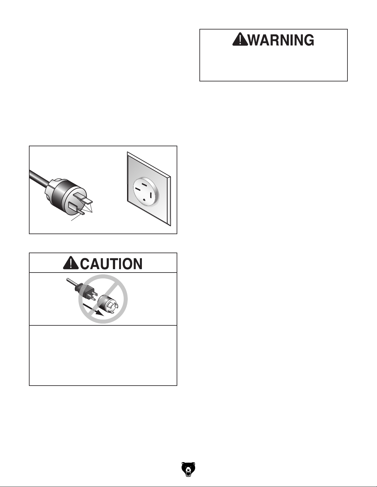
The power cord and plug specified under “Circuit
Requirements for 220V”
has an equipment-grounding wire and a ground
ing prong. The plug must only be inserted into
a matching receptacle (outlet) that is properly
installed and grounded in accordance with all
local codes and ordinances (see figure below).
No adapter should be used with the
available receptacle, or the machine must
on the previous page
GROUNDED
15-15 RECEPTACLE
15-15 PLUG
Current
Carrying
Grounding Prong
Prongs
Serious injury could occur if you connect
the machine to power before completing the
setup process. DO NOT connect to power
until instructed later in this manual.
-
Extension Cords
Figure 2. NEMA 15-15 plug and outlet.
required plug. If the plug does not fit the
be reconnected for use on a different type
of circuit, the reconnection must be made
by a qualified electrician and comply with all
local codes and ordinances.
Model G0756 (Mfg. Since 2/13)
If you must use an extension
Minimum Gauge Size ...........................14 AWG
Maximum Length (Shorter is Better).......50 ft.
-11-
Page 14
SECTION 3: SETUP
Your machine was carefully packaged for safe
transportation. Remove the packaging materials
from around your machine and inspect it. If you
discover any damage, please call us immediately
at (570) 546-9663
Save the containers and all packing materials for
possible inspection by the carrier or its agent.
Otherwise, filing a freight claim can be difficult.
When you are completely satisfied with the condition of your shipment, inventory the contents.
Keep children and pets away
from plastic bags or packing
materials shipped with this
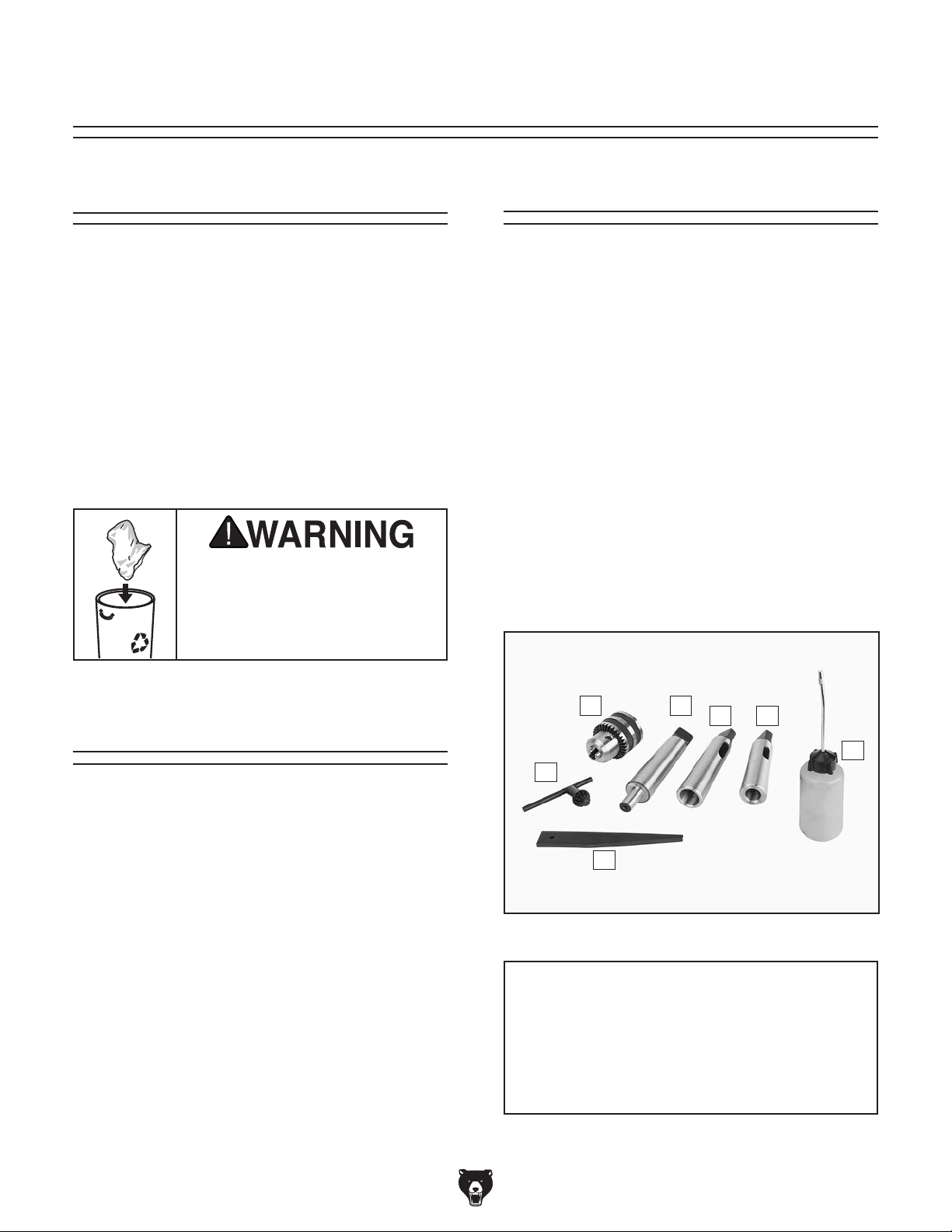
The following is a list of items shipped with your
machine. Before beginning setup, lay these items
out and inventory them.
If any non-proprietary parts are missing (e.g. a
nut or a washer), we will gladly replace them; or
for the sake of expediency, replacements can be
obtained at your local hardware store.
Unpacking
for advice.
SUFFOCATION HAZARD!
Inventory
Inventory (see Figure 3): Qty
A. Drill Chuck B16 3–16mm ............................ 1
B. Drill Chuck Arbor MT#4–B16 ...................... 1
C. Spindle Sleeve MT#4–MT#3 ...................... 1
D. Spindle Sleeve MT#4–MT#2 ...................... 1
E. Bottle for Oil ............................................... 1
F. Drift Key ...................................................... 1
G. Chuck Key .................................................. 1
H. Toolbox (not shown) ................................... 1
machine. Discard immediately.
Needed for Setup
The following are needed to complete the setup
process, but are not included with your machine.
Description Qty
• Additional People ....................................... 1
• Safety Glasses ........................ 1 Per Person
• Cleaner/Degreaser ..................... As Needed
• Disposable Shop Rags ............... As Needed
• Forklift ......................................................... 1
• Lifting Straps (Rated 1500 lbs. Minimum) .. 1
• Steel Bar Stock 1" x 3' ................................ 1
-12-
A
G
F
Figure 3. Toolbox inventory.
B
DC
E
NOTICE
If you cannot find an item on this list, carefully check around/inside the machine and
packaging materials. Often, these items get
lost in packaging materials while unpacking or they are pre-installed at the factory.
Model G0756 (Mfg. Since 2/13)
Page 15
The unpainted surfaces of your machine are
coated with a heavy-duty rust preventative that
prevents corrosion during shipment and storage.
This rust preventative works extremely well, but it
will take a little time to clean.
Be patient and do a thorough job cleaning your
machine. The time you spend doing this now will
give you a better appreciation for the proper care
of your machine's unpainted surfaces.
There are many ways to remove this rust preventative, but the following steps work well in a wide
variety of situations. Always follow the manufacturer’s instructions with any cleaning product you
use and make sure you work in a well-ventilated
area to minimize exposure to toxic fumes.
Before cleaning, gather the following:
• Disposable rags
• Cleaner/degreaser (WD•40 works well)
• Safety glasses & disposable gloves
• Plastic paint scraper (optional)
Basic steps for removing rust preventative:
1.
2.
3.
4.
Many cleaning solvents
work in a well-ventilated
Avoid chlorine-based solvents, such as
Cleanup
Gasoline and petroleum
products have low flash
points and can explode
or cause fire if used to
clean machinery. Avoid
using these products
to clean machinery.
Put on safety glasses.
Coat the rust preventative with a liberal
amount of cleaner/degreaser, then let it soak
for 5–10 minutes.
Wipe off the surfaces. If your cleaner/degreas-
er is effective, the rust preventative will wipe
off easily. If you have a plastic paint scraper,
scrape off as much as you can first, then wipe
off the rest with the rag.
are toxic if inhaled. Only
area.
NOTICE
acetone or brake parts cleaner, that may
damage painted surfaces.
T23692—Orange Power Degreaser
A great product for removing the waxy shipping
grease from your machine during clean up.
Figure 4. T23692 Orange Power Degreaser.
Repeat Steps 2–3 as necessary until clean,
then coat all unpainted surfaces with a quality
metal protectant to prevent rust.
Model G0756 (Mfg. Since 2/13)
-13-
Page 16
Site Considerations
Weight Load
Physical Environment
Place this machine near an existing power source.
Shadows, glare, or strobe effects that may distract
or impede the operator must be eliminated.
Refer to the Machine Data Sheet for the weight
of your machine. Make sure that the surface upon
which the machine is placed will bear the weight
of the machine, additional equipment that may be
installed on the machine, and the heaviest workpiece that will be used. Additionally, consider the
weight of the operator and any dynamic loading
that may occur when operating the machine.
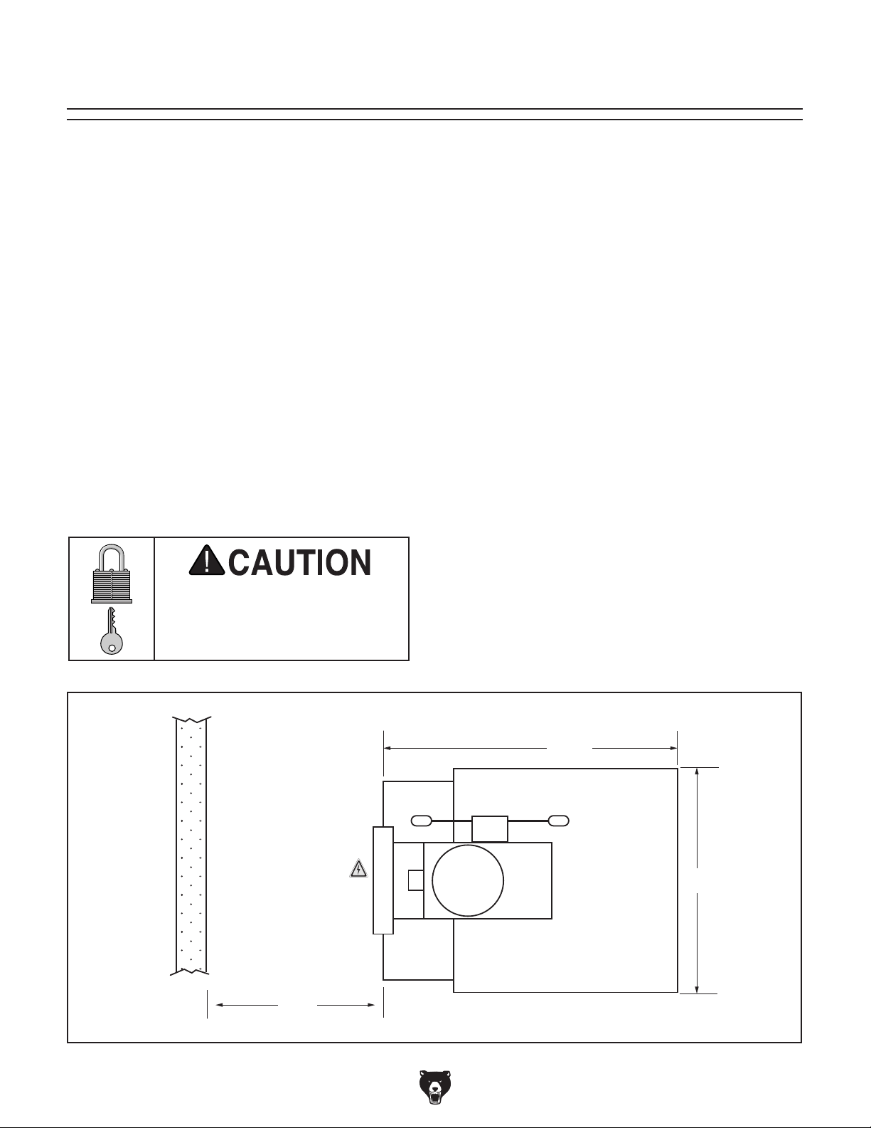
Space Allocation
Consider the largest size of workpiece that will
be processed through this machine and provide
enough space around the machine for adequate
operator material handling or the installation of
auxiliary equipment. With permanent installations,
leave enough space around the machine to open
or remove doors/covers as required by the maintenance and service described in this manual.
See below for required space allocation.
Children or untrained people
may be seriously injured by
this machine. Only install in an
access restricted location.
The physical environment where the machine is
operated is important for safe operation and longevity of machine components. For best results,
operate this machine in a dry environment that is
free from excessive moisture, hazardous chemicals, airborne abrasives, or extreme conditions.
Extreme conditions for this type of machinery are
generally those where the ambient temperature
range exceeds 41°–104°F; the relative humidity
range exceeds 20–95% (non-condensing); or the
environment is subject to vibration, shocks, or
bumps.
Electrical Installation
Make sure all power cords are protected from
traffic, material handling, moisture, chemicals,
or other hazards. Make sure to leave access to
a means of disconnecting the power source or
engaging a lockout/tagout device, if required.
Lighting
Lighting around the machine must be adequate
enough that operations can be performed safely.
-14-
Wall
30" minimum for
maintenance
37 1⁄2"
22"
30"
Figure 5. Minimum working clearances.
Model G0756 (Mfg. Since 2/13)
Page 17
Lifting & Placing
lifting machine or some of
get help from other people
Anchoring machinery to the floor prevents tipping
or shifting and reduces vibration that may occur
during operation, resulting in a machine that runs
slightly quieter and feels more solid.
If the machine will be installed in a commercial or
workplace setting, or if it is permanently connected (hardwired) to the power supply, local codes
may require that it be anchored to the floor.
If not required by any local codes, fastening the
machine to the floor is an optional step. If you
choose not to do this with your machine, we recommend placing it on machine mounts, as these
provide an easy method for leveling and they have
vibration-absorbing pads.
Lag shield anchors with lag screws (see below)
are a popular way to anchor machinery to a concrete floor, because the anchors sit flush with the
floor surface, making it easy to unbolt and move
the machine later, if needed. However, anytime
local codes apply, you MUST follow the anchoring
methodology specified by the code.
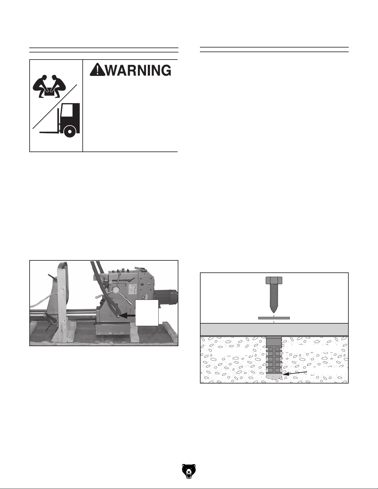
HEAV Y LIFT!
Straining or crushing injury
may occur from improperly
its parts. To reduce this risk,
and use a fork lift (or other
lifting equipment) rated for
weight of this machine.
To move and place this drill:
1. Place shipping crate near final machine
mounting location.
Anchoring to Floor
2. Remove top portion of crate from the ship-
ping pallet, secure the ends of a properly
rated lifting strap around each side of the bar
placed through the lifting holes, and attach it
securely to your power lifting equipment (see
Figure 6).
Bar In
Figure 6. Strap around bar in lifting hole.
3. Unbolt the machine from the pallet.
4. With another person to help to steady the
machine, lift it just enough to clear the pallet
and any floor obstacles, then place it in its
final position.
Lifting
Hole
Anchoring to Concrete Floors
Lag Screw
Flat Washer
Machine Base
Concrete
Figure 7. Popular method for anchoring
machinery to a concrete floor.
Lag Shield Anchor
Drilled Hole
Model G0756 (Mfg. Since 2/13)
-15-
Page 18
Arbor/Chuck
Assembly
Initial Lubrication
An arbor is included for the drill chuck that
comes with this machine. The following procedure
describes how to install the arbor in the chuck.
After the arbor is installed in the drill chuck, it
is very difficult to separate the assembly. If you
would like to use a different chuck in the future,
we suggest using a different arbor.
Important: DO NOT install the drill chuck and
arbor assembly until AFTER the test run.
To connect the drill chuck with the arbor:
1. Use acetone or lacquer thinner to clean drill
chuck and arbor mating surfaces, especially
the bore.
2. Retract the chuck jaws so that they are not
exposed.
3. Insert the arbor into the drill chuck.
GEARBOX MUST
BE FILLED WITH OIL!
OIL MAY NOT BE
SHIPPED WITH MACHINE!
Refer to Lubrication Section
for Correct Oil Type.
To prevent spillage, this machine was shipped
from the factory without any oil in it. The headstock oil reservoir must be properly filled with oil
before the drill press can be operated for the first
time. Refer to the Lubrication section, beginning
on Page 33, for details on how to check and add
oil.
4. Hold assembly by the arbor and tap chuck
onto a block of wood with moderate force
(see Figure 8).
Figure 8. Installing arbor into chuck.
Damage caused by running the drill press
without oil in the reservoir will not be covered under warranty.
-16 -
Model G0756 (Mfg. Since 2/13)
Page 19
Power Connection
30 31 32 33 34 35 E
W1 U2 V2 W2 10 12
COM
10 11 12 13 14 15 16 17 QO
PE
Master Power Switch
L
753
1
864
2
R
A2
2 T1 6 T3 22NC4 T2
1 L1 5 L3
21NC
Tianshui 123
GSC1-1201
KM1
3 L2
A1
Contactor
A2
2 T1 6 T3 22NC4 T2
1 L1 5 L3
21NC
Tianshui 123
GSC1-1201
KM2
3 L2
A1
Contactor
A2
13NO 23NO 33NO 43NO
14NO 24NO 34NO 44NO
Tianshui 123
JZC3-40d
KA1
A1
Contactor
26 25 24 23 22 21 20
TC
20-21 = 220V
20-22 = 230V
20-23 = 380V
20-24 = 400V
20-25 = 415V
20-26 = 440V
Transformer
To High/Low
Gear Switch
To Electronic
Clutch
To Control
Panel
To
Pump
JBK5-100VATH
ON
OFFONOFF
ON
OFF
ON
OFF
ON
OFF
CM X11 X13 CM X15 X17 CM
• • X10 X12 • X14 T +24v
Special Controller
EX-30tA1-B
E&E
••••••••
CM2CM
2
•••••Y7Y6Y5Y4
U2 V2 W2
QM5 QM3 QM2 QM1 QM4
CM
0
36
35
35
36
Q3
U1
U1V1V1
W1
W1
2L3
2L3
ZL22L13L1 3L3
2L1
3L13L3
22
21L3L2L1
1131
20 X1X3
CM
22
Q2
Q3
Q0
Y0
Q1
Y3Y2Y1
CM
2
CM
1
12
12
10
X2
X4 X6
3021 11103120
X5 X7
L X1 X3 CM X5 X7
N X0 X2 X4 X6
12
2L1 ZL2 2L3
2L3ZL2
ZL2
2L1
3L1
3L3
1010
Q1
10
32
32
L1
L3
L2
CanSen
LW26GS-20
C1 C3 D1 D10 C1
DZ451-63 DZ451-63 DZ451-63 DZ451-63 DZ451-63
W1 10 12 X1U2 V2 W2 X2 X3 X4 X5 X6 X7 QO
COM
PE
L1 L2 L3 U1 V1 W1 U2 V2 W2 10 12 X1 X2 X3 X4 X5 X6 X7 QO
L1
L2
L3
COM
PLC
Q2
PE
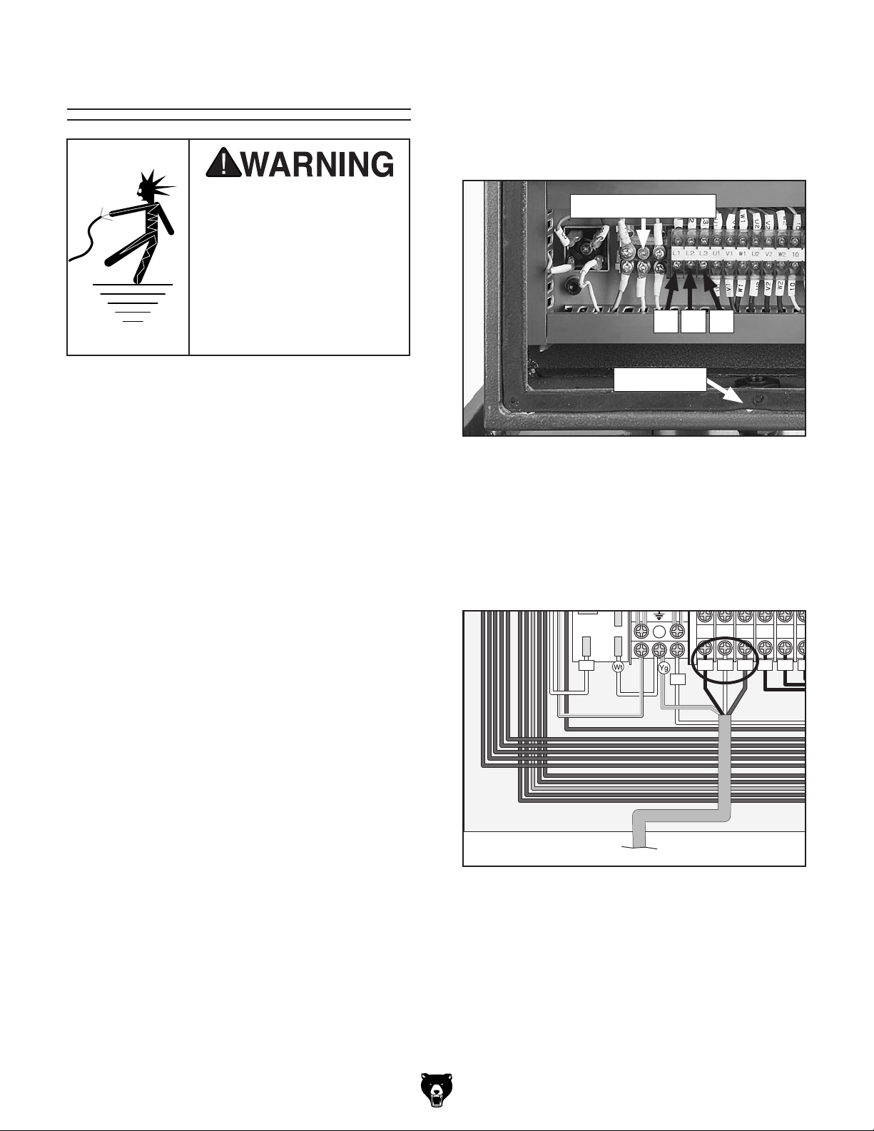
2. Identify the L1, L2, and L3 terminals and the
grounding terminal (see Figure 9).
Electrocution or fire
may occur if machine is
ungrounded, incorrectly
Before the machine can be connected to the
connected to an undersized circuit. Use an electrician or a qualified service
personnel to ensure a safe
power connection.
connected to power, or
power source, an electrical circuit must be made
available that meets the minimum specifications
given in Circuit Requirements for 220V on Page
10. If a power circuit has not been prepared for the
machine, do that now.
To minimize the risk of electrocution, fire, or
equipment damage, all installation work and electrical wiring MUST be done by an electrician or
qualified service personnel.
Note about extension cords: Using an incor-
rectly sized extension cord may decrease the life
of electrical components on your machine. Refer
to Extension Cords on Page 11 for more information.
To connect the power cord to the machine:
3. Thread the power cord through the strain
relief shown in Figure 9.
Grounding Terminal
L3L1 L2
Strain Relief
Figure 9. Location of hot wire terminals, ground
terminal, and strain relief.
4. Connect the incoming hot wires and ground
wire to the terminals shown in Figure 10.
Note: If using a phase convertor, the "wild
wire" is connected to the L2 terminal.
Mager
KBPC10-10
30
L1 L2 L3 U1 V1
L1 L2 L3 U1 V1
COM
1. Turn the master power switch to OFF, then
open the electrical cabinet door located at the
back of the machine.
Model G0756 (Mfg. Since 2/13)
To Plug/Power Supply
Figure 10. Ground and hot wires connected.
-17-
Page 20
5. Make sure the power cord and wires have
slack between the strain relief and terminal
connections so that they do not bind, then
tighten the strain relief to secure the cord.
If, during the test run, you cannot easily locate
the source of an unusual noise or vibration, stop
using the machine immediately, then review
Troubleshooting on Page 35.
Note: The strain relief must be tightened
against the outer jacket of the cord. Avoid
over-tightening the strain relief or it may
crush the cord and cause a short.
6. Test the strain relief to ensure it is properly
tightened by pulling the cord from outside the
box with light-to-moderate force. When the
strain relief is properly tightened, the cord will
not move inside the cabinet.
7. Install a NEMA 15-15 plug on the other end
of the power cord per the plug manufacturer's
instructions.
8. Close and secure the main electrical box
door.
9. Plug the power cord into a power source with
a matching receptacle, as specified in Circuit
Requirements for 220V on Page 10.
Note: If you discover during the Test Run that
the drill press will not operate, or that the spindle
runs backwards, the drill press may be wired out
of phase.
If you still cannot remedy a problem, contact our
Tech Support at (570) 546-9663 for assistance.
Before starting the drill press, make sure
you have performed the preceding setup
instructions, and you have read through the
rest of the manual and are familiar with the
various functions and safety features on
this machine. Failure to follow this warning
could result in serious personal injury or
even death!
To test run the machine:
1. Make sure all tools and objects used during
setup are cleared away from the machine.
2. Make sure the machine is properly lubricated.
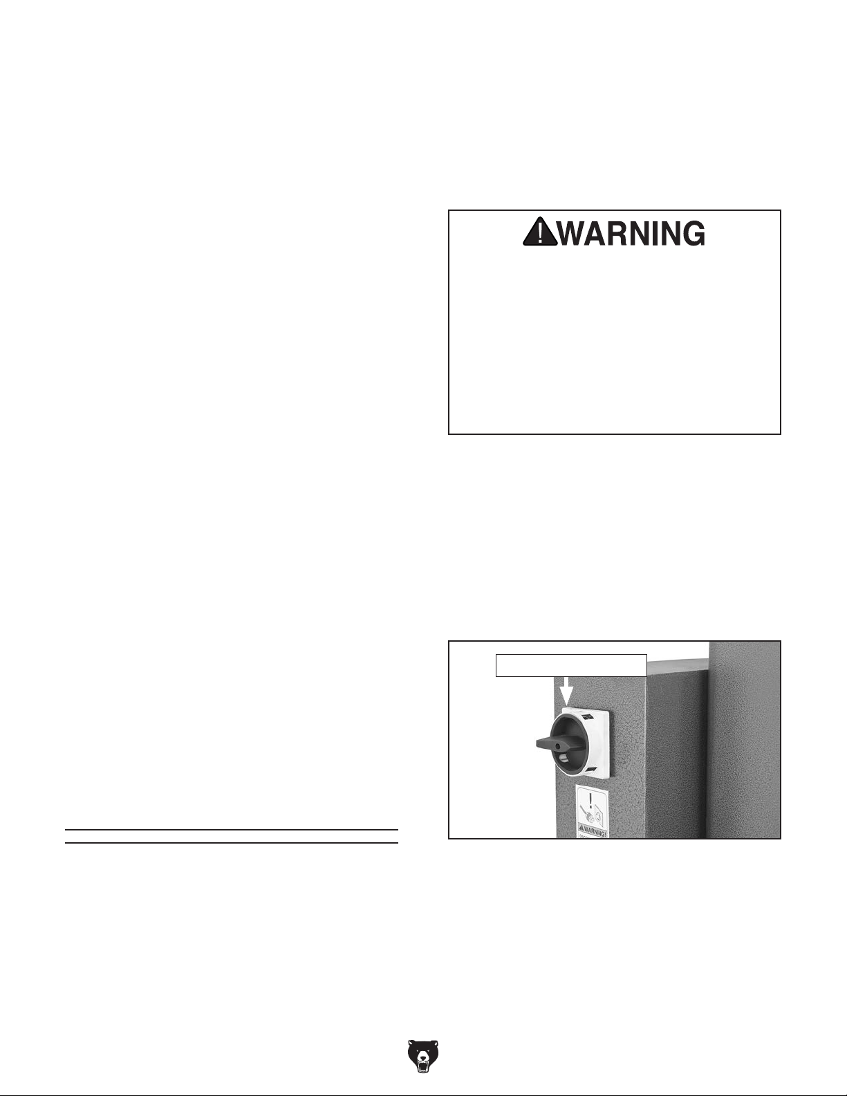
3. Turn the Master Power Switch (Figure 11)
ON.
Correcting the phase polarity requires reversing
the positions where the L1 and L3 wires are connected. Due to the high voltage and risk of serious
shock involved, we strongly recommend this procedure only be done by an electrician or qualified
service personnel.
Test Run
Once the preceding setup procedures are complete, test run your machine to make sure it runs
properly and is ready for regular operation.
The test run consists of verifying the following:
1) The motor powers up and runs correctly, 2)
the EMERGENCY STOP button and chip guard
safety features work correctly, and 3) the motor
rotates in the correct direction (machine is not
wired out of phase).
Master Power Switch
Figure 11. Master power switch.
-18-
Model G0756 (Mfg. Since 2/13)
Page 21

4. Press the EMERGENCY STOP button
(Figure 12) in, then twist it clockwise so
it pops out. When the botton pops out the
switch is reset and ready for operation.
EMERGENCY
STOP Button
Spindle
Start
Button
Figure 12. Resetting the switch.
Spindle
Stop
Button
6. Press the EMERGENCY STOP button and
ensure that the drill press comes to a complete stop.
7. WITHOUT resetting the EMERGENCY STOP
button, press the spindle start button. The
machine should not start.
—If the machine does not start, the
EMERGENCY STOP button safety feature
is working correctly.
—If the machine does start (with the
EMERGENCY STOP button pressed
in), immediately disconnect power to the
machine. The EMERGENCY STOP button
safety feature is not working correctly. This
safety feature must work properly before
proceeding with regular operations. Call
Tech Support for help.
5. Verify that the machine is operating correctly
by turning the spindle rotation switch to the
left position and pressing the spindle start
button.
—When operating correctly, the machine
runs smoothly with little or no vibration or
rubbing noises.
— Investigate and correct strange or unusual
noises or vibrations before operating the
machine further. Always stop the machine
and disconnect it from power before investigating or correcting potential problems.
—Verify that oil is flowing through the head-
stock by examining the oil flow sight glass
for oil movement (see Page 33).
—If the spindle direction switch is turned to
the left and the bit turns from right to left
(as standing in front of the machine), it is
turning in the correct direction.
8. Press the EMERGENCY STOP button in,
then twist it clockwise so it pops out. When
the button pops out, the switch is reset and
ready for operation.
9. Rotate the chip guard out of position and
press the spindle start button. The machine
should not start.
—If the machine does not start, the chip
guard safety feature is working correctly.
—If the machine starts, immediately discon-
nect power to the machine. This safety feature must work properly before proceeding
with regular operations. Call Tech Support
for help.
Congratulations! The test run is now com-
plete. Before beginning any regular operations, perform the Spindle Break-In procedure on Page 21.
—If the bit turns from left to right (as standing
in front of the machine), see Page 17 for
instructions on correcting phase polarity.
Model G0756 (Mfg. Since 2/13)
-19 -
Page 22

Test Coolant System
3. Turn the Coolant Pump Switch to the ON
position.
This drill press comes with a pump-driven cycling
coolant system. Prior to testing the coolant system, add two gallons of coolant to the coolant reservoir. Refer to Changing Coolant on Page 28.
To test the coolant system:
1. Wear safety goggles and other protective
clothing.
2. Aim the coolant nozzle into the trough to
reduce splash (see Figure 13).
Table trough
Coolant Drain
4. Adjust the ball valve in the coolant nozzle
assembly for the proper coolant flow (see
Figure 14).
Ball valve
Figure 14. Ball valve of nozzle assembly.
5. Close the ball valve and turn the pump switch
to the OFF position.
Figure 13. Table trough and coolant drain.
Running the pump without adequate coolant can significantly damage the pump,
which will not be covered under warranty.
-20-
Model G0756 (Mfg. Since 2/13)
Page 23

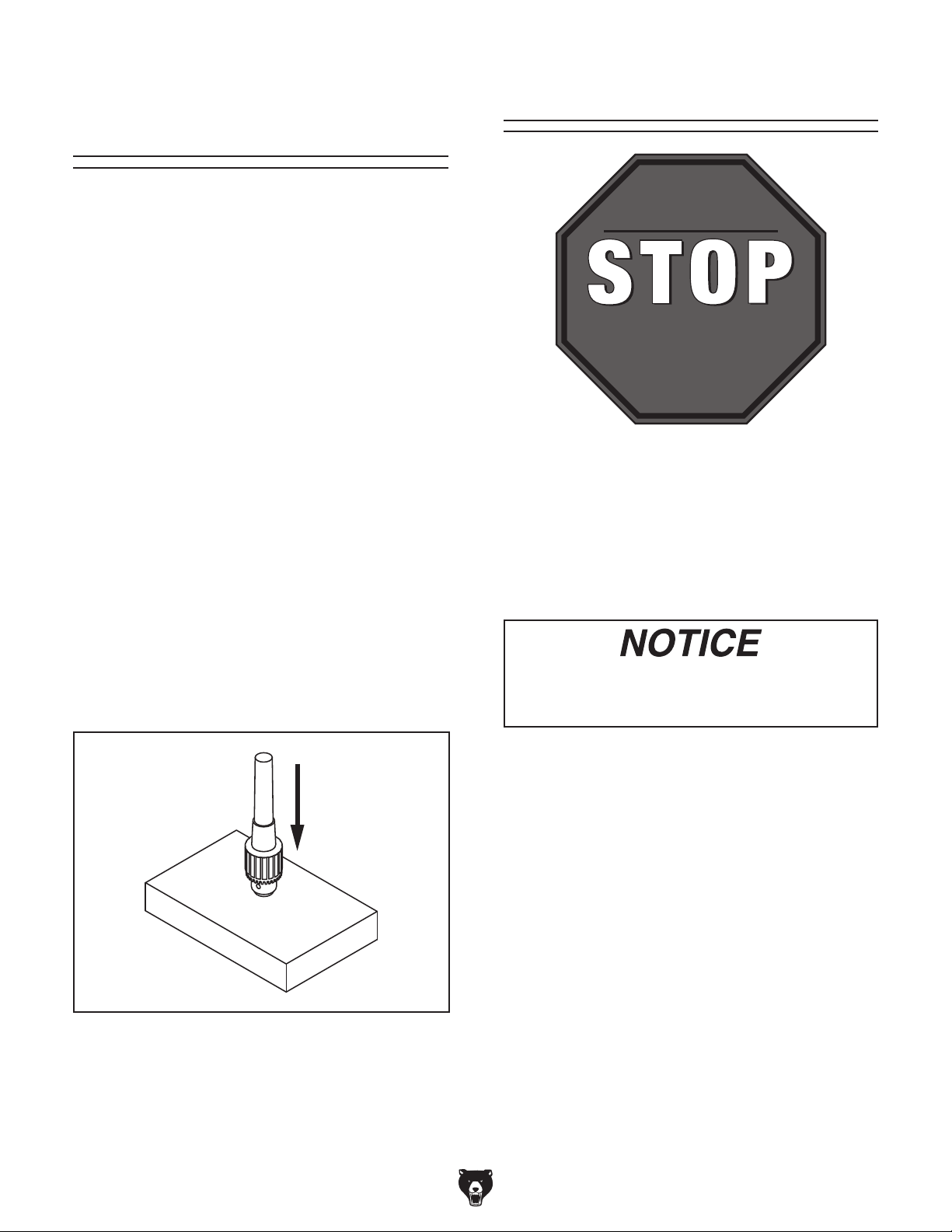
Spindle Break-In
Before subjecting the spindle to operational loads,
it is essential to complete the break-in process.
This helps ensure maximum life of spindle bearings and other precision components by thoroughly lubricating them before placing them under
load.
After spindle break-in is complete, we recommend
changing headstock and gearbox oil to remove
any metal particles or debris that are present from
the assembly and break-in process.
To perform the spindle break-in procedure:
1. Move the drilling & tapping switch to the drill-
ing position (see Figure 15).
Drilling and
Tapping
Switch
The break-in must be performed in succession
with the Test Run procedure described in this
manual, as the steps in that procedure prepare
the drill press for the break-in process.
DO NOT perform this procedure independently of the Test Run section. The drill
press could be seriously damaged if the
controls are set differently than instructed
in that section.
Spindle
Start Button
Figure 15. Drilling/tapping switch.
2. Position the speed control levers for 440
RPM.
3. Press the spindle start button.
4. Allow the machine to run for 10 minutes.
5. Press the spindle stop button.
6. Position the speed control levers for 870
RPM, and allow machine to run for 10 minutes.
7. Press the OFF button, and adjust the speed
control levers for 440 RPM.`
8. Press the spindle start button.
Model G0756 (Mfg. Since 2/13)
9. Press the button on the end of the downfeed
handle to reverse spindle rotation.
10. Run the machine at 440 RPM and then 870
RPM for 10 minutes each, as described
above.
11. Run the machine at 440 RPM for another 15
minutes to allow it cool down.
Congratulations! Spindle break-in is complete. We
recommend changing the headstock and gearbox
oil before operating the machine further (refer to
lubrication on Page 33).
-21-
Page 24

SECTION 4: OPERATIONS
To reduce your risk of
serious injury, read this
entire manual BEFORE
To reduce risk of eye injury from flying
Operations Overview
To complete a typical operation, the operator
does the following:
The purpose of this overview is to provide the novice machine operator with a basic understanding
of how the machine is used during operation, so
the machine controls/components discussed later
in this manual are easier to understand.
Due to the generic nature of this overview, it is
not intended to be an instructional guide. To learn
more about specific operations, read this entire
manual and seek additional training from experienced machine operators, and do additional
research outside of this manual by reading "howto" books, trade magazines, or websites.
using machine.
1. Examines the workpiece to make sure it is
suitable for drilling.
2. Puts on the required safety gear.
3. Firmly secures the workpiece to the table
using a vise or T-slot clamps.
4. Installs the correct cutting tool for the operation.
5. Adjusts table to the correct height, then locks
it in place.
6. Connects the machine to power, and turns
the master power switch ON.
7. Selects the spindle RPM with the speed
control levers and presses the spindle start
button.
8. Begins drilling.
chips or lung damage from breathing dust,
always wear safety glasses and a respirator
when operating this machine.
If you are not experienced with this type
of machine, WE STRONGLY RECOMMEND
that you seek additional training outside of
this manual. Read books/magazines or get
formal training before beginning any projects. Regardless of the content in this section, Grizzly Industrial will not be held liable
for accidents caused by lack of training.
9. When finished, presses the spindle stop but-
ton and disconnects it from power.
Tooling Installation &
Removal
This machine has an MT#4 spindle for installing tooling. It is also equipped with an automatic
drift for easy removal of tooling (see Figure 16).
Additionally, a drift key is included to manually
remove the tooling from the spindle, if needed.
-22-
Model G0756 (Mfg. Since 2/13)
Page 25

Installing Tapered Tooling
1. DISCONNECT MACHINE FROM POWER!
2. Clean tooling and spindle tapers to ensure
proper seating.
3. Insert the MT#4 tooling into the spindle, and
maneuver the tang until it engages with the
slot at the end of the spindle.
3. While holding onto the tooling, raise the
spindle to the original position. It should automatically release from the spindle.
4. Pull the automatic drift knob back to the outward position.
Removing Tooling Manually
1. DISCONNECT MACHINE FROM POWER!
4. Use a rubber or wooden mallet to seat the
tooling into the spindle by firmly tapping from
the bottom.
Note: If installing a drill chuck, make sure to
retract the jaws to prevent damage to chuck.
Removing Tooling with Automatic
Drift
1. DISCONNECT MACHINE FROM POWER!
2. Lower the spindle with the coarse downfeed
handle until you can press in the automatic
drift knob (see Figure 16).
Automatic Drift
2. Lower the quill and rotate the spindle by hand
until the drift key holes in the spindle and quill
are aligned (see Figure 17).
Figure 17. Spindle and quill drift key holes
aligned.
3. Insert the drift key into the aligned holes and
allow the quill to rise, trapping the drift key.
Figure 16. Automatic drift knob.
Leaving the automatic drift knob pressed in
can result in the arbor coming free the next
time it is inserted into the spindle sleeve.
An improperly installed arbor can become
a projectile and result in serious injury to
operator or others nearby. Always verify
arbor is correctly installed before beginning
drilling operations.
Model G0756 (Mfg. Since 2/13)
4. Softly tap the end of the key while holding the
arbor/chuck assembly until it separates from
the spindle (see Figure 18).
Figure 18. Using drift key to remove arbor.
-23-
Page 26

Depth Stop
This drill press includes a depth stop for drilling
multiple holes at the same depth.
7. Press the spindle start button.
8. Drill a hole into scrap stock before drilling into
any workpiece to ensure the depth has been
set correctly. If necessary, repeat Steps 2–5.
To set the depth stop:
1. DISCONNECT MACHINE FROM POWER!
2. Adjust the table height so the workpiece is
close to the work tool.
3. Mark the side of your workpiece at the intended cutting depth (see Figure 19 ).
Workpiece
Drill Bit
Scrap Wood
Workpiece
Depth
Mark
Table
Figure 19. Depth stop mark on workpiece.
Table Positioning
The table for this drill press moves vertically
and rotates 360 degrees to accommodate larger
workpieces.
Raising/Lowering Table
1. Remove any objects from the table surface.
2. Loosen the release handles shown in Figure
21).
3. Adjust the table height by rotating the height
adjustment handle (see Figure 21).
Height
Adjustment
Handle
4. Secure the workpiece to the table with a
clamp or vise.
5. Place the workpiece on the table, and lower
the spindle until the tip of the bit is even with
the mark.
6. Loosen the depth stop handle, move the drill
bit to the required drilling depth, and tighten it
(see Figure 20).
Depth Stop Handle
Lock Handles
Figure 21. Column Release and Height
Adjustment Handles.
Rotating Table
1. Remove all objects from the table surface.
2. Slightly loosen the lock handles (see Figure
21).
3. Push the table to the desired location, and
guide the rack on the side of the column.
4. Re-tighten the lock handles.
Figure 20. Setting depth stop handle.
-24-
Model G0756 (Mfg. Since 2/13)
Page 27

Selecting Spindle
RPM
Use the proper spindle speed and feed rate to
reduce strain on all moving parts and decrease
risk of operator injury.
Prior to drilling, determine the RPM needed for
workpiece material then set the spindle speed to
the closest available RPM.
To determine the needed RPM:
1. Use the table in Figure 22 to determine the
speed required for your workpiece material.
Twist/Brad Point Drill Bits Soft Wood Hard Wood Plastic Brass Aluminum Mild Steel
1/16" – 3/16" 3000 2500 2500 2500 3000 2500
13/64" – 3/8" 2000 1500 2000 1250 2500 1250
25/64" – 5/8" 1500 750 1500 750 1500 600
11/16" – 1" 750 500 1000 400 1000 350
Note:
ting speed. These values are a guideline only.
Refer to the MACHINERY'S HANDBOOK for
more detailed information.
For carbide cutting tools, double the cut-
Larger bits turning at slower speeds tend
to grab the workpiece aggressively. This
can result in the operator's hand being
pulled into the bit or the workpiece being
thrown with great force. Always clamp the
workpiece to the table to prevent injuries.
pade/Forstner Bits Soft Wood Hard Wood Plastic Brass Aluminum Mild Steel
S
1/4" – 1/2" 2000 1500
9/16" – 1" 1500 1250
1-1/8" – 1-7/8" 1000 750
2–3" 500 350
ole Saws Soft Wood Hard Wood Plastic Brass Aluminum Mild Steel
H
1/2" – 7/8" 500 500 600 600 600 500
1" – 1-7/8" 400 400 500 500 500 400
2" – 2-7/8" 300 300 400 400 400 300
3" – 3-7/8" 200 200 300 300 300 200
4" – 5" 100 100 200 200 200 100
osette Cutters Soft Wood Hard Wood Plastic Brass Aluminum Mild Steel
R
Carbide Insert Type 350 250
One-Piece Type 1800 500
T
enon/Plug Cutters Soft Wood Hard Wood Plastic Brass Aluminum Mild Steel
3/8" – 1/2" 1200 1000
5/8" – 1" 800 600
Figure 22. Cutting speed table for HSS cutting tools.
Model G0756 (Mfg. Since 2/13)
-25-
Page 28

Drilling Mode
This drill press is designed for vertical drilling and
tapping operations. For repeated drilling at the
same depth, there is a power downfeed mechanism. For tapping convenience, there is an automatic clutch used for reversing the direction of the
spindle while in tapping mode by pressing one of
the buttons at the ends of each course downfeed
handle.
Overloading tools or using excessive spindle speeds may cause parts or broken tools
to hit operator, resulting in serious impact
injuries.
To drill a workpiece:
1. Refer to Controls on Page 4 to understand
the functions of each control.
Speed Control Levers
Drilling/Taping Switch
Figure 23. Controls for drilling.
2. Clamp the workpiece to the table, and adjust
the depth stop for the needed depth of cut.
Note: Drilling with the quill fully extended
can cause tool chatter. For maximum spindle
rigidity, keep the spindle retracted into the
headstock as far as possible.
3. Put on safety glasses, a face shield, and
close the chip guard.
4. Select the "drilling" mode option with the
toggle switch.
5. Refer to Selecting Spindle RPM on Page
25, and choose the closest available spindle
RPM.
6. Turn the Master Power Switch ON.
7. Press the spindle start button and begin the
drilling operation.
-26-
Model G0756 (Mfg. Since 2/13)
Page 29

Automatic Power
Downfeed
This drill press comes with automatic downfeed
control for repeated drilling operations at the
same depth. The automatic downfeed only works
in the drilling mode.
Stay clear of coarse downfeed handles
while using the automatic downfeed. When
the depth stop triggers the lower elevation
limit switch, the handles spin rapidly as
the spindle returns to its starting position.
Failure to stay clear of the handles may
result in injury.
To operate the automatic power downfeed:
4. Match the lines on the adjustment knob to
select an automatic power downfeed option
(see Figure 24).
—There are three options for the power
downfeed mechanism that are located on the
side of the adjustment knob:
• 0.2 is equal to 2mm of downfeed per
spindle rotation.
• 0.1 is 1mm of downfeed per spindle
rotation.
• 0.0 disengages the downfeed mechanism.
Adjustment Knob
Automatic
Power
Downfeed
Option Lines
1. DISCONNECT MACHINE FROM POWER!
2. Select the drilling option with the drilling/tap-
ping switch.
3. Set the spindle depth stop to the desired
position (refer to Page 24).
Figure 24. Automatic downfeed adjustment
knob.
5. Re-connect machine to power.
6. Turn the Master Power Switch ON, and press
the spindle start button.
7. Pull the coarse downfeed handle down
towards the front of the machine until the
automatic downfeed begins.
Model G0756 (Mfg. Since 2/13)
-27-
Page 30

Tapping Mode
Coolant System
When in tapping mode, the spindle direction
can immediately alternate between forward and
reverse by pressing any of the three buttons at the
end of the downfeed handles. This feature is critical to back the tap out of a hole before it bottoms
out and snaps off, as well as clearing away waste
chips during the tapping process.
Pilot holes must be drilled prior to beginning any
tapping operation.
To use tapping mode:
1. DISCONNECT MACHINE FROM POWER!
2. Determine the maximum tapping depth with-
out bottoming-out the tap, and adjust the
depth stop accordingly.
3. Clamp the workpiece to the table.
4. Put on safety glasses and a face shield.
Select tapping mode, and turn the spindle
rotation switch counter-clockwise.
This machine comes with a coolant system for
use in drilling and tapping operations. This feature
promotes precision cutting and tool longevity.
To operate the coolant system:
1. Ensure there is a sufficient amount of clean
coolant in the reservoir (refer to Page 20 for
detailed instructions).
2. Aim the coolant nozzle at the contact area of
the workpiece and the work tool.
3. Turn the coolant pump switch on the control
panel to the ON position.
4. Regulate the coolant flow to the contact area
using the coolant ball valve shown in Figure
25.
Coolant Ball Valve
5. Install the tap, and apply tapping fluid to the
contact point of the tap and workpiece.
6. Connect the machine to power.
7. Select "tapping" mode with the drilling/tap-
ping switch
8. Select the appropriate spindle speed. Speeds
vary according to the material, bit, and procedure. There are several online resources to
choose from for calculating spindle speed
9. Press the spindle start button.
10. Begin threading. Without disengaging the
tap from the threads, frequently alternate
spindle rotation by pressing any end button
to reverse spindle and eject chips from the
hole. Frequently removing chips will prevent
galling and tap breakage.
Figure 25. Coolant ball valve.
-28-
Model G0756 (Mfg. Since 2/13)
Page 31

SECTION 5: ACCESSORIES
order online at www.grizzly.com or call 1-800-523-4777
G1075—52-PC. Clamping Kit
This clamping kit includes 24 studs, 6 step block
pairs, 6 T-nuts, 6 flange nuts, 4 coupling nuts, and
6 end hold-downs. The rack is slotted so it can be
mounted close to the machine for easy access.
Made for
Installing unapproved accessories may
cause machine to malfunction, resulting in
serious personal injury or machine damage.
To reduce this risk, only install accessories
recommended for this machine by Grizzly.
NOTICE
Refer to our website or latest catalog for
additional recommended accessories.
G5753—Drill Press Vise - 6"
If you use a drill press and value your fingers, you
need one of these. Made from high-grade cast
iron, these hefty horizontal vises offer support
and stability, allowing you to keep your hands well
away from fast moving bits and cutters. Includes
a sturdy lip along both sides of the base, allowing
vise to be mounted to nearly any machine table,
using common T-slot clamps.
1
⁄2 " T-slots.
Figure 27. Clamping Kit.
T20501—Face Shield Crown Protector 4"
T20502—Face Shield Crown Protector 7"
T20503—Face Shield Window
T20452—"Kirova" Anti-Reflective S. Glasses
T20451—"Kirova" Clear Safety Glasses
H0736—Shop Fox
H7194—Bifocal Safety Glasses 1.5
H7195—Bifocal Safety Glasses 2.0
H7196—Bifocal Safety Glasses 2.5
®
Safety Glasses
Figure 26. Cast iron drill press vice.
Figure 28. Safety glasses.
Model G0756 (Mfg. Since 2/13)
-29-
Page 32

T23962—ISO 68 Moly-D Way Oil, 5 gal.
T23963—ISO 32 Moly-D Machine Oil, 5 gal.
Moly-D oils are some of the best we've found for
maintaining the critical components of machinery
because they tend to resist run-off and maintain
their lubricity under a variety of conditions—as
well as reduce chatter or slip. Buy in bulk and
save with 5-gallon quantities.
G3658—Titanium Drill Bits
Titanium nitride-coated bits last up to six times as
long as uncoated bits. This 115-piece set features
1
29 fractional bits, from
1
⁄64", letter bits from A–Z, and 60 number bits.
of
⁄6" to 1⁄2 " in increments
Housed in rugged steel case.
T23962
T23963
Figure 29. ISO 68 and ISO 32 machine oil.
H7527—6" ROTARY TABLE SET
Use this 6" Rotary Table in either the horizontal
or vertical position for a variety of milling applications and with the set of dividing plates and
adjustable tailstock, your milling applications are
nearly unlimited. With 4° table movement per handle rotation and 20 second vernier scale, control
3
is very accurate and precise. Also includes a
⁄8"
clamping set for the 4-slot table. Everything you
need in one great set!
Figure 31. 115 piece drill bit set.
H7616—Oil Can w/Plastic Nozzle
H7617—Oil Can w/Flexible Plastic Nozzle
These high-pressure oil cans are perfect for lubricating the ball oilers found on your machine. Each
can holds 5 ounces of oil.
Figure 30. Rotary table with dividing plates.
H7616
H7617
Figure 32. High pressure oil cans.
-30-
Model G0756 (Mfg. Since 2/13)
Page 33

H7819—Drill & Tap HSS 24 pc. Set
Our new High Speed Steel Tap and Drill Set
comes supplied with 6 of the most commonly
used coarse thread sizes. What's more, each size
has taps with plug, bottoming and taper grinds
allowing you to choose the right tap for any job.
The set includes the following tap sizes and corre-
1
sponding drill bits: 8-32 & #29, 10-24 & #25,
5
& #7,
⁄16"-18 & F, 3⁄8"-16 & 5⁄16" and 1⁄2 "-13 & 27⁄64".
⁄4"-20
1
H8262—
⁄2" x MT#4 Keyless Chuck with
Integral Shank
Precision, Keyless Drill Chucks have integral
shanks to fit a variety of spindles including Morse
taper, R8 and Cat 40. Each chuck has a knurled
grip for plenty of torque and if that’s not enough,
they’re spanner wrench compatible. (Spanner
wrench not included.) Made in an ISO 9001 certified factory.
Figure 34. Precision keyless drill chuck.
Figure 33. Commonly used tap and drill set.
Model G0756 (Mfg. Since 2/13)
-31-
Page 34

SECTION 6: MAINTENANCE
To reduce risk of shock or
accidental startup, always
disconnect machine from
power before adjustments,
maintenance, or service.
Schedule
Typically, each operator is responsible for ensuring proper care of the equipment. We strongly
recommend all operators make a habit of following the daily maintenance procedures.
Daily, After Operations
• Thoroughly clean the machine and protect all
surface areas
• Press the EMERGENCY STOP button and
shut OFF the master power switch (to prevent accidental startup).
• Remove any rotary tables, vises, fixtures, or
workpieces from the table to prevent rusting
the table surface.
Annually
• Disconnect machine from power, open electrical box, and clean with compressed air.
Ongoing
To reduce the risk of injury and ensure proper
machine operation, if you ever observe any of the
items below, shut down the machine immediately
and fix the problem before continuing operations:
• Loose mounting bolts or fasteners.
• Worn, frayed, cracked, or damaged wires.
• Chip guard removed.
• EMERGENCY STOP button not working correctly or not requiring you to reset it before
starting the machine again.
• Any other unsafe condition.
Every 8 hour of operation:
• Lubricate the ball oilers (Page 34).
• Check/Add headstock oil (Page 33).
• Check quantity/quality of coolant (Page 20).
Annually:
• Change headstock oil (Page 33).
Cleaning and
Protecting
Metal chips left on the machine will invite oxidation and a gummy residue build-up around the
moving parts. Use a brush and shop vacuum to
remove chips and debris from the working surfaces of the drill press. Never blow off the drill
press with compressed air, as this will force metal
chips deep into the mechanisms and may cause
injury to yourself or bystanders.
Remove any rust build-up from unpainted cast
iron surfaces of your drill press and treat with a
non- staining lubricant after cleaning.
Keep unpainted cast iron surfaces rust-free with
regular applications of ISO 68 way oil (see Page
30 for offerings form Grizzly).
-32-
Model G0756 (Mfg. Since 2/13)
Page 35

Lubrication
For the quill, table, and column, an occasional
application of light machine oil is all that is necessary. Before applying lubricant, clean off any dust
or metal chips.
Your goal is to achieve adequate lubrication. Too
much lubrication will attract dirt and dust. Various
parts of your machine could lose their freedom of
movement as a result.
Headstock Lubrication
Oil Ty p e ......Model T23963 or ISO 32 Equivalent
Oil Amount ........................................... 4
Lubrication Frequency ........................... Annually
The headstock uses an oil pump to lubricate the
gears. For this machine, use ISO 68 machine
oil. Check the oil level every day (see Step 4).
Change oil annually.
3
⁄4 quarts
Do not fill headstock with oil above the red
mark. This could damage the machine and
create an overflow of oil.
Red Mark
Site Glass
Location
Figure 36. Site glass location.
5. Re-install the oil fill plug.
To change oil in headstock:
1. Remove the oil fill plug on top of the machine
(see Figure 35).
Oil Fill Plug
Oil Drain Plug
Figure 35. Oil fill and drain locations.
2. Remove the drain plug, and allow old oil to
drain into an appropriate container.
6. Discard used oil following federal, state, and
fluid manufacturer guidelines for proper disposal.
Oil Flow Sight Glass
This machine comes with an oil flow sight glass
(see Figure 37). Examine the flow sight glass
during machine operation to ensure that the oil is
properly circulating within the headstock.
If oil is not circulating, and headstock has proper
amount of oil, shut down machine immediately
and call tech support.
Oil Flow Sight Glass
3. Replace and tighten the drain plug.
4. Fill the headstock with oil to the red mark on
the site glass (see Figure 36).
Model G0756 (Mfg. Since 2/13)
Figure 37. Oil flow sight glass.
-33-
Page 36

Ball Oilers
Oil Ty p e ......Model T23963 or ISO 32 Equivalent
Oil Amount ......................................... 1–2 Pumps
Lubrication Frequency ........8 Hours of Operation
This machine has four ball oilers as shown in
Figures 38–39. Use an oil gun fitted with a rubber tip wide enough to seal the ball oiler inlet. We
do not recommend using metal needle or lance
tips, as they can push the ball too far into the oiler,
break the spring seat, and lodge the ball in the oil
galley.
Push the tip of the oil can nozzle against the ball
oiler to create a hydraulic seal, then pump the oil
can once or twice. If you see sludge and contaminants coming out of the lubrication area, continue
pumping the oil can until the oil runs clear. When
finished, wipe away the excess oil.
Changing Coolant
Coolant is consistently cycled and stored in the
base reservoir beneath the pump. For efficient
operation and tool longevity, replace coolant when
it runs low or becomes dirty from excessive use.
BIOLOGICAL & POISON HAZARD!
Use the correct personal protection equipment when handling coolant. Follow federal, state, and fluid manufacturer requirements for proper disposal.
To replace the coolant:
1. Pump coolant into an empty 5-gallon bucket.
As soon as coolant stops coming out, shut off
pump.
Ball Oilers
Figure 38. Table support bracket ball oiler
locations.
Ball Oilers
2. DISCONNECT MACHINE FROM POWER!
3. Put on gloves, safety glasses, and respira-
tor. Loosen the cap screws and remove the
reservoir lid (see Figure 40).
Coolant Reservoir Lid
Figure 40. Coolant reservoir.
4. Use a wet/dry shop vacuum to remove any
coolant and debris from inside the reservoir.
Figure 39. Headstock side ball oiler locations
-34-
5. Refill the reservoir with fresh coolant.
6. Replace the reservoir lid and re-tighten the
cap screws.
Model G0756 (Mfg. Since 2/13)
Page 37

Review the troubleshooting and procedures in this section if a problem develops with your machine. If you
need replacement parts or additional help with a procedure, call our Technical Support at (570) 546-9663.
Note: Please gather the serial number and manufacture date of your machine before calling.
SECTION 7: SERVICE
Troubleshooting
Motor & Electrical
Symptom Possible Cause Possible Solution
Machine does not
start or a breaker
trips
Machine stalls or is
overloaded.
Machine has
vibration or noisy
operation.
1. Emergency stop push-button engaged/at
fault.
2. Chuck guard open/safety switch at fault.
3. Spindle position limit switch engaged/at
fault.
4. Power supply switched OFF or at fault.
5. Plug/receptacle at fault/wired wrong.
6. Motor connection wired wrong.
7. Wall circuit breaker tripped.
8. Wiring open/has high resistance.
9. Master power switch at fault.
10. Motor or motor components at fault.
1. Feed rate/cutting speed too fast.
2. Wrong tooling.
3. Machine is undersized or tooling is incorrect
for the task.
4. Motor connection is wired incorrectly.
5. Motor bearings are at fault.
6. Motor has overheated.
7. Motor or motor components at fault.
1. Excessive depth of cut.
2. Tooling is loose or improperly installed.
3. Machine is incorrectly anchored or sits
unevenly.
4. Motor or machine component is loose.
5. Tooling is dull or at fault.
6. Bit is chattering.
7. Motor fan is rubbing on fan cover.
8. Motor bearings are at fault.
1. Rotate button to reset/replace it.
2. Close guard/replace switch.
3. Adjust spindle position to disengage limit switch;
replace switch.
4. Ensure power supply is on/has correct voltage.
5. Test for good contacts; correct the wiring.
6. Correct motor wiring connections (Page 41).
7. Ensure circuit size is correct/replace weak breaker.
8. Check/fix broken, disconnected, or corroded wires.
9. Replace switch.
10. Test/repair/replace.
1. Decrease feed rate/cutting speed.
2. Use the correct tool for the task.
3. Use smaller or sharper tool; reduce feed rate or
spindle speed; use coolant if possible.
4. Correct motor wiring connections (Page 41).
5. Test by rotating shaft; rotational grinding/loose shaft
requires bearing replacement.
6. Clean off motor, let cool, and reduce workload.
7. Test/repair/replace motor.
1. Decrease depth of cut.
2. Make sure tooling is properly secured.
3. Tighten/replace anchors; relocate/shim machine.
4. Inspect/replace stripped or damaged bolts/nuts, and
re-tighten with thread locking fluid.
5. Replace/resharpen tooling.
6. Replace/sharpen bit; index bit to workpiece; use
appropriate feed rate and cutting RPM.
7. Replace dented fan cover or damaged fan.
8. Test by rotating shaft; rotational grinding/loose shaft
requires bearing replacement.
Model G0756 (Mfg. Since 2/13)
-35-
Page 38

Drill Press Operations
Symptom Possible Cause Possible Solution
Breaking tools or cutters. 1. Spindle speed/feed rate is too fast.
2. Cutting tool getting too hot.
3. Spindle extended too far down.
Drilling stops, but the motor
still operates.
The chuck wobbles or is
loose on the spindle shaft.
The spindle does not retract
completely in the uppermost
position or it binds.
1. Bit slips in chuck. 1. Tighten bit; inspect bit for burrs or other obstructions
1. Foreign material is stuck between
the arbor-to-spindle mating surface.
2. Damaged chuck or arbor.
1. The quill shaft is gummy with metal
chips and oil.
1. Set spindle speed correctly (Page 25) or use a
slower feed rate.
2. Use coolant or oil for appropriate application.
3. Fully retract spindle and lower headstock. This
increases rigidity.
that might interfere with clamping surface.
1. Remove the arbor/chuck assembly and clean the
tapered arbor and spindle mating surfaces, then
reassemble.
2. Replace as necessary.
1. Clean shaft and lubricate with a light coat of oil.
The quill has excessive
deflection.
Drill bit wobbles, holes are
oversized.
Workpiece vibrates or
chatters during operation.
1. The quill bearings are worn or
damaged.
2. The quill shaft is at fault.
1. Drill bit installed incorrectly. 1. Remove drill bit and re-install.
1. Table locks not tight.
2. Workpiece not securely clamped to
table or into drill vice.
3. Spindle speed/feed rate is too fast.
4. Spindle extended too far down.
1. Replace the bearings.
2. Replace the quill shaft.
1. Tighten table release handles (Page 24).
2. Check that clamping is tight and sufficient for the job.
Make sure drill vice is tight to the table.
3. Set spindle speed correctly (Page 25) or use a
slower feed rate.
4. Fully retract spindle and raise table. This increases
rigidity.
-36-
Model G0756 (Mfg. Since 2/13)
Page 39

Replacing Lamp
Bulb
The work lamp bulb in this machine is a 24V 25W
two pronged halogen bulb. The replacement part
number for the bulb is P0756418-1.
Torque Limiter
The torque limiter regulates how much torque
is applied to the drive shaft of the drill press to
prevent the machine from mechanical overload. It
was adjusted at the factory according to the maximum axial load.
To replace the bulb in the work lamp:
1. DISCONNECT MACHINE FROM POWER!
2. Using a Phillips head screwdriver, remove
the three screws that hold the work lamp
cover in place.
3. Remove the bulb (see Figure 41).
Eventual wear on the limiter discs may require
compensatory adjustment to the torque limiter.
Overtightening can break the torque limiter.
Make less than quarter turn adjustments at
one time.
To adjust the torque limiter:
1. DISCONNECT MACHINE FROM POWER!
2. Remove the two cap screws that hold the
plastic cover on the side of the headstock.
3. Rotate the spindle by hand until the set screw
on the torque limiter is visible (see Figure
42).
Set Screw
Figure 41. Work lamp bulb replacement.
4. Insert the new bulb and replace the work
lamp cover.
Model G0756 (Mfg. Since 2/13)
Torque Limiter
Figure 42. Torque limiter and set screw.
4. Turn the set screw less than a quarter of a
turn using a 4mm hex wrench. One small
adjustment should compensate for any wear
on the limiter disc.
-37-
Page 40

These pages are current at the time of printing. However, in the spirit of improvement, we may make changes to the electrical systems of future machines. Compare the manufacture date of your machine to the one
number and manufacture date of your
machine before calling. This information can be found on the main machine label.
machine
SECTION 8: WIRING
stated in this manual, and study this section carefully.
If there are differences between your machine and what is shown in this section, call Technical Support at
(570) 546-9663 for assistance BEFORE making any changes to the wiring on your machine. An updated
wiring diagram may be available. Note: Please gather the serial
Wiring Safety Instructions
SHOCK HAZARD. Working on wiring that is connected to a power source is extremely dangerous.
Touching electrified parts will result in personal
injury including but not limited to severe burns,
electrocution, or death. Disconnect the power
from the machine before servicing electrical components!
MODIFICATIONS. Modifying the wiring beyond
what is shown in the diagram may lead to unpredictable results, including serious injury or fire.
This includes the installation of unapproved aftermarket parts.
WIRE CONNECTIONS. All connections must
be tight to prevent wires from loosening during
machine operation. Double-check all wires disconnected or connected during any wiring task to
ensure tight connections.
CIRCUIT REQUIREMENTS. You MUST follow
the requirements at the beginning of this manual when connecting your machine to a power
source.
WIRE/COMPONENT DAMAGE. Damaged wires
or components increase the risk of serious personal injury, fire, or machine damage. If you notice
that any wires or components are damaged while
performing a wiring task, replace those wires or
components.
MOTOR WIRING. The motor wiring shown in
these diagrams is current at the time of printing
but may not match your machine. If you find this
to be the case, use the wiring diagram inside the
motor junction box.
CAPACITORS/INVERTERS. Some capacitors
and power inverters store an electrical charge for
up to 10 minutes after being disconnected from
the power source. To reduce the risk of being
shocked, wait at least this long before working on
capacitors.
EXPERIENCING DIFFICULTIES. If you are experiencing difficulties understanding the information
included in this section, contact our Technical
Support at (570) 546-9663.
The photos and diagrams
included in this section are
best viewed in color. You
can view these pages in
color at www.grizzly.com.
-38-
Model G0756 (Mfg. Since 2/13)
Page 41

Master
Power
Switch
Page 45
Coolant
Pump Motor
Page 41
Electrical
Panel
Page 45
Wiring Overview
Spindle Motor
Page 41
Control
Panel
Page 43
Work Lamp
Page 41
Power Supply Connection
Page 40
Elevation Limit
Switches
Page 43
Chip Guard
Limit Switch
Page 43
Electronic
Clutch
Page 40
Spindle Motor
Page 41
Master Power
Switch
Page 45
Electrical
Panel
Page 45
Power Plug
Page 40
Coolant
Pump
Page 41
Component Location Index
Control
Panel
Page 43
d
Elevation Limit
Switches
b
i
Work Lamp
Page 41
Page 43
Chip Guard
Limit Switch
Page 43
Model G0756 (Mfg. Since 2/13)
READ ELECTRICAL SAFETY
ON PAGE 38!
-39-
Page 42

Power Connection Wiring
W
Z
G
X
13
QO
PE
Hot
Ground
Hot
220 VAC
3-Phase
Hot
15-15 Plug
(as recommended)
Electric Clutch Wiring
To Electrical
Panel
Page 45
Ground
Gd.
Front View
-40-
Side view
READ ELECTRICAL SAFETY
ON PAGE 38!
Figure 43. Electronic clutch wiring.
Model G0756 (Mfg. Since 2/13)
Page 43

To
Ground
PE
U1
W2
V1
U2
W1
V2
Control
Panel
Page 43
Motor & Pump Wiring
SPINDLE MOTOR
Figure 44. Spindle motor wiring.
Ground
PE
V2
U2
W2
To
Control
Panel
Page 43
W1
U2
V1
V2
U1
W2
PUMP MOTOR
WORK LAMP
13
10
To
Electrical
Panel
Page 45
Figure 45. Coolant pump wiring.
Model G0756 (Mfg. Since 2/13)
Figure 46. Work lamp wiring.
READ ELECTRICAL SAFETY
ON PAGE 38!
-41-
Page 44

Control Panel
To Lamp
Page 41
To Electrical Panel
Page 45
12
C2SS2-10B-10 C2SS2-10B-10
LAMP SWITCH
2
MCB-01
1
Left
View
Right
View
To Electrical Panel
Page 45
X5
PUMP SWITCH
U1
2
4
W2
U1
1 3 5 7 9 1113
8612
U2
10 14
V1
16
W1
V1
15
To Spindle Motor
Page 41
PE
Ground
X6
X6
LX5W-A11N
Upper
Elevation
Limit
Switch
V2
10
Chip
Guard
Limit
Switch
EMERGENCY STOP
X4
C2SS2-10B-10
DRILLING/TAPPING SWITCH
COM
4
MCB-01 MLB-01
3
12
X1
X2
X1
10
START BUTTON
W1
HIGH/LOW GEAR SWITCH
X2
C2SS2-10B-10
SPINDLE DIRECTION
CP1-10R-01
STOP BUTTON
(Viewed from behind)
Lower
Elevation
Limit
Switch
LX5W-A11N
X7
X7
Ground
PE
Machine Frame
-42-
READ ELECTRICAL SAFETY
ON PAGE 38!
Model G0756 (Mfg. Since 2/13)
Page 45

Control Panel & Limit Switches
Chip Guard
Limit Switch
Figure 47. Chip Guard limit switch
location.
Lamp Switch
Upper Elevation
Limit Switch
Pump Switch
Emergency
Stop Button
Drilling/Tapping
Mode Switch
Start Button
High/Low
Gear Switch
Spindle Direction
Switch
Stop Button
Lower Elevation
Limit Switch
Figure 31. Control panel and limit switch locations (viewed from behind).
Model G0756 (Mfg. Since 2/13)
READ ELECTRICAL SAFETY
ON PAGE 38!
-43-
Page 46

Electrical Panel Wiring
Master Power Switch
L2
26 25 24 23 22 21 20
20-21 = 220V
20-22 = 230V
20-23 = 380V
20-24 = 400V
20-25 = 415V
20-26 = 440V
Transformer
JBK5-100VATH
30 31 32 33 34 35 E
20
3021
20 X1X3
22
L X1 X3 CM X5 X7
10
N X0 X2 X4 X6
CM
X2
• • X10 X12 • X14 T +24v
E&E
Special Controller
EX-30tA1-B
Y0
Y3Y2Y1
Q0
Q2
Q1
Q3
CM2CM
CM
CM
2
0
1
3L13L3
TC
111031
X5 X7
CM X11 X13 CM X15 X17 CM
X4 X6
CM
2
1131
DZ451-63 DZ451-63 DZ451-63 DZ451-63 DZ451-63
QM5 QM3 QM2 QM1 QM4
C1 C3 D1 D10 C1
ON
OFFONOFF
32
12
ON
OFF
2L1 ZL2 2L3
10
A1
1 L1 5 L3
3 L2
Tianshui 123
GSC1-1201
ON
OFF
21NC
ZL22L13L1 3L3
Q2
A1
Contactor
PLC
•••••Y7Y6Y5Y4
••••••••
KM1
2 T1 6 T3 22NC4 T2
U1V1V1
W1
A2
35
36
21L3L2L1
ON
OFF
2L3
22
2L1
3 L2
1 L1 5 L3
Tianshui 123
GSC1-1201
Contactor
KM2
2 T1 6 T3 22NC4 T2
W1
2L3
2L1
2L3ZL2
U1
Q1
21NC
35
3L1
1010
A1
13NO 23NO 33NO 43NO
Tianshui 123
JZC3-40d
Contactor
14NO 24NO 34NO 44NO
A2
36
U2 V2 W2
ZL2
KA1
L3
3L3
864
L3
753
L2
2
L1
1
L1
LW26GS-20
L
R
CanSen
A2
Q3
-44-
12
12
To High/Low
Gear Switch
32
COM
Mager
KBPC10-10
30
PE
PE
L1 L2 L3 U1 V1 W1 U2 V2 W2 10 12 X1 X2 X3 X4 X5 X6 X7 QO
PE
L1 L2 L3 U1 V1 W1 U2 V2 W2 10 12
L1 L2 L3 U1 V1 W1 10 12 X1U2 V2 W2 X2 X3 X4 X5 X6 X7 QO
COM
To Plug/Power Supply
READ ELECTRICAL SAFETY
ON PAGE 38!
To
Pump
To Control
Panel
COM
10 11 12 13 14 15 16 17 QO
COM
To Electronic
Model G0756 (Mfg. Since 2/13)
Clutch
Page 47

Electrical Wiring Panel Photo
Model G0756 (Mfg. Since 2/13)
Figure 48. Electrical wiring panel.
READ ELECTRICAL SAFETY
ON PAGE 38!
-45-
Page 48

SECTION 9: PARTS
Please Note: We do our best to stock replacement parts whenever possible, but we cannot guarantee that all parts shown here
are available for purchase. Call (800) 523 -4777 or visit our online parts store at www.grizzly.com to check for availability.
Table Support & Coolant Breakdown
14
34
33
13
11
32
27
26
25
24
23
28
29
30
31
18
20
19
10
9
8
7
15
6
16
17
5
4
3
2
22
21
1
-46-
Model G0756 (Mfg. Since 2/13)
Page 49

Table Support & Coolant Parts List
REF PART # DESCRIPTION REF PART # DESCRIPTION
1 P0756001 BASE 19 P0756019 DRAIN PLUG 3/8" NPT SOCKET HEAD
2 P0756002 COOLANT PUMP MOUNT 20 PCAP209M CAP SCREW M14-2 X 60
3 PCAP26M CAP SCREW M6-1 X 12 21 P0756021 COOLANT RESERVOIR COVER PLATE
4 P0756004 COOLANT PUMP 22 PCAP31M CAP SCREW M8-1.25 X 25
5 PCAP26M CAP SCREW M6-1 X 12 23 P0756023 REDUCING NIPPLE 1/2" X 3/8" NPT
6 P0756006 HANDLE SHAFT 3/8"-16 x 3" 24 P0756024 ELBOW
7 P0756007 CRANK ARM 25 P0756025 FLEXIBLE TUBE 16 X 1.5 X 1300MM
8 PSS127M SET SCREW M10-1.5 X 10 PILOT 26 P0756026 COOLANT RETURN HOSE
9 P0756009 CLAMP COLLAR 27 P0756027 COUPLING
10 P0756010 WORM GEAR M16-2 28 P0756028 TEE
11 P0756011 ADJUSTABLE HANDLE M16 X 114 29 PSS16M SET SCREW M8-1.25 X 10
13 PCAP49M CAP SCREW M6-1 X 60 30 PLUBE002M BALL OILER 8MM TAP-IN
14 P0756014 HEADSTOCK MOUNT 31 P0756031 GEAR SHAFT
15 P0756015 GEAR 15T 32 P0756032 TABLE SUPPORT
16 PCAP13M CAP SCREW M8-1.25 X 30 33 P0756033 TABLE
17 P0756017 RACK 34 PCAP122M CAP SCREW M16-2 X 50
18 P0756018 COLUMN
Model G0756 (Mfg. Since 2/13)
-47-
Page 50

Gearbox Breakdown
134
133
132
131
130
101
103
104
105
106
107
102-1
102-2
102-4 102-5
102
102-3
129
128
127
126
125
124
123
122
121
108
109
135 136
118119
117
110
111
112
113
114
115
114
116
-48-
Model G0756 (Mfg. Since 2/13)
Page 51

137
143
Gearbox Breakdown 2
142
141
138
144
139
140
148
147
146
145
156
149
157
151
150
158
152
159
160
165
153
166
154
161
167
168
155
162
169
154
164
155
156
163
172
171
155
170
164
155
156
180
179
178
174
173
Model G0756 (Mfg. Since 2/13)
175
176
177
181
182
183
184
185
186
-49-
Page 52

Gearbox Parts List
REF PART # DESCRIPTION REF PART # DESCRIPTION
101 P0756101 GEARBOX HOUSING 142 P0756142 SPLINED SHAFT
102 P0756102 MOTOR 2HP 220V 3-PH 4/8-POLE 143 PR32M EXT RETAINING RING 48MM
102-1 P0756102-1 MOTOR FAN COVER 144 P0756144 GEAR 34T
102-2 P0756102-2 MOTOR FAN 145 P0756145 KEY 8 X 5 X 32
102-3 P0756102-3 JUNCTION BOX 146 P0756146 GEAR 46T
102-4 P0756102-4 FRONT MOTOR BEARING 6206 2RZ 147 P0756147 GEAR 40T
102-5 P0756102-5 REAR MOTOR BEARING 6206 2RZ 148 PR32M EXT RETAINING RING 48MM
103 PW04M FLAT WASHER 10MM 149 P6008-OPEN BALL BEARING 6008-OPEN
104 PCAP210M CAP SCREW M10-1.5 X 35 C12.9 150 P0756150 SPACER
105 P0756105 MOTOR GASKET 151 PR38M INT RETAINING RING 62MM
106 P0756019 DRAIN PLUG 3/8" NPT HEX HEAD 152 P0756152 COVER
107 PCAP31M CAP SCREW M8-1.25 X 25 153 P0756153 O-RING 58 X 2.65
108 P0756108 SIGHT GLASS M27 X 1.5 154 PR38M INT RETAINING RING 62MM
109 P0756109 SIGHT GLASS B20 x M27-1.5 155 P6206-OPEN BALL BEARING 6206-OPEN
110 P0756110 DRAIN PLUG M27-2 HEX HEAD 156 P0756156 FLANGED BUSHING
111 P0756111 PLUG 157 P0756157 GEAR 48T
112 PCAP31M CAP SCREW M8-1.25 X 25 158 P0756158 GEAR 48T
113 P0756113 SHIFT LEVER 159 P0756159 GEAR SHAFT
114 P0756114 SHIFT FORK 160 P0756145 KEY 8 X 5 X 32
115 P0756115 SHAFT 161 P0756161 KEY 8 X 5 X 40
116 P0756116 SHIFT LEVER 162 P0756162 GEAR 22T
117 P0756117 SHAFT 163 P0756163 GEAR 28T
118 PCAP14M CAP SCREW M8-1.25 X 20 164 P0756164 COVER
119 P0756119 POINTER PIN 165 PCAP01M CAP SCREW M6-1 X 16
121 P0756121 HANDLE LEVER 166 P0756166 DOWEL PIN 10 X 40MM
122 P0756122 RIGHT SHIFT HUB 167 P0756167 FLANGE
123 P0756123 LEFT SHIFT HUB 168 P0756168 O-RING 58 X 2.65
124 P0756124 COMPRESSION SPRING 1 X 9 X 18-2 169 PSS97M SET SCREW M3-.5 X 4
125 PSTB005M STEEL BALL 10MM 170 P0756170 GEAR 12T
126 P0756126 O-RING 17 X 1.8 171 P0756171 FLANGED BUSHING
127 PR09M EXT RETAINING RING 20MM 172 P0756172 SPLINED SHAFT
128 PS08M PHLP HD SCR M5-.8 X 12 173 P0756173 GEAR 20T
129 P0756129 GEAR CHANGE PLATE 174 P0756174 KEY 6 X 4 X 36
130 PRP59M ROLL PIN 5 X 12 175 P0756175 GEAR 34T
131 P0756019 DRAIN PLUG 3/8" NPT HEX HEAD 176 P0756176 GEAR 12T
132 P0756132 LUBRICATION TUBE 177 P0756177 GEAR 50T
133 PCAP03M CAP SCREW M5-.8 X 8 178 PR12M EXT RETAINING RING 35MM
134 P0756134 TUBE CLIP 179 PR11M EXT RETAINING RING 25MM
135 P0756135 GEARBOX COVER GASKET 180 P0756180 GEAR 50T
136 P0756136 GEARBOX COVER 181 PCAP14M CAP SCREW M8-1.25 X 20
137 P0756137 SPLINED FLANGE SLEEVE 182 PLW04M LOCK WASHER 8MM
138 P0756138 O-RING 61.5 X 3.55 183 PWF08M FENDER WASHER 8MM
139 P0756139 OIL SEAL 40 X 55 X 08MM 184 P0756184 GEAR SHAFT
140 PR70M INT RETAINING RING 68MM 185 P0756185 KEY 6 X 4 X 28
141 P6008-2RS BALL BEARING 6008-2RS 186 P0756186 SHAFT
-50-
Model G0756 (Mfg. Since 2/13)
Page 53

201
202
Spindle Feed Breakdown
203
204
205
206
207
210
224
212
213
214
225
215
226
216
227
217
228
218
219
220
221
208
222
209
223
230
Model G0756 (Mfg. Since 2/13)
231
229
232
233
-51-
Page 54

Spindle Feed Parts List
REF PART # DESCRIPTION REF PART # DESCRIPTION
201 PS14M PHLP HD SCR M6-1 X 12 218 P16005-OPEN BALL BEARING 16005-OPEN
202 P0756202 PLATE 219 PR25M INT RETAINING RING 47MM
203 PRP09M ROLL PIN 6 X 5 220 P0756220 FEED HANDLE HUB
204 P0756204 COILED SPRING 221 P0756221 SPANNER NUT M24-1.5
205 P0756205 GEAR SHAFT 222 P0756222 HUB COVER PLATE
206 P0756206 WOODRUFF KEY 8 X 5 223 PCAP110M CAP SCREW M4-.7 X 6
207 P0756206 WOODRUFF KEY 8 X 5 224 P0756224 HEADSTOCK FEED COVER GASKET
208 PR73M EXT RETAINING RING 5MM 225 PCAP110M CAP SCREW M4-.7 X 6
209 P0756209 WORM GEAR 226 P0756226 BRACKET
210 P0756210 ELECTROMAGNETIC TOOTH CLUTCH 227 P0756227 NUT
212 P0756212 ARMATURE 228 P0756228 BRUSH
213 PCAP16M CAP SCREW M4-.7 X 16 229 PCAP12M CAP SCREW M8-1.25 X 40
214 P0756214 FLANGED BUSHING 230 P0756230 HANDLE SHAFT W/BUTTON HOUSING
215 P0756215 GEAR SHAFT SPACER-LARGE 231 P0756231 BUTTON RETAINER NUT
216 P0756216 GEAR SHAFT SPACER-SMALL 232 P0756232 HEADSTOCK FEED SPINDLE COVER
217 PR25M INT RETAINING RING 47MM 233 PRP86M ROLL PIN 8 X 45
-52-
Model G0756 (Mfg. Since 2/13)
Page 55

Headstock Breakdown
382
331
314
315
322
323 324 325
313
316 317
312
311
310
318
308309
319
320
306307
321
305
304
303
302
301
330 332
Model G0756 (Mfg. Since 2/13)
333
334
335
336
337
326
327
328
329
340
339
338
341 342
-53-
Page 56

343
Headstock Breakdown 2
344
353
352
351
350
349
348
356
345
357
368
346
358
369
359
370
347
360
371
361
362
372
354
363
373
377
364
355
374
367
366
365
376
375
381
380
-54-
378
379
Model G0756 (Mfg. Since 2/13)
Page 57

Headstock Parts List
REF PART # DESCRIPTION REF PART # DESCRIPTION
301 P0756301 HEADSTOCK HOUSING 343 P0756343 SPINDLE
302 P0756302 AUTO DOWNFEED SHIFTING FORK 344 P0756344 QUILL
303 P0756303 DOWEL PIN 10 X 20MM 345 PR97M EXT RETAINING RING 75MM
304 P0756304 AUTO DOWNFEED SHIFTING SHAFT 346 P0756346 O-RING 85 X 5.7
305 P0756305 AUTO DOWNFEED INDICATOR HUB 347 P0756347 THRUST WASHER
306 PSS128M SET SCREW M8-1.25 X 25 PILOT 348 P51108 THRUST BEARING 51108
307 P0756307 AUTOMATIC DOWNFEED DIAL 349 P0756349 NEEDLE ROLLER BEARING RNA49/32
308 PSTB003M STEEL BALL 6MM 350 P0756350 SPRING HOUSING
309 P0756309 COMPRESSION SPRING 0.8 X 5 X 16 351 P6006-2RS BALL BEARING 6006-2RS
310 PSS06M SET SCREW M8-1.25 X 16 352 P0756352 CLAMP NUT
311 PSTB003M STEEL BALL 6MM 353 PCAP41M CAP SCREW M4-.7 X 14
312 P0756312 COMPRESSION SPRING 0.8 X 7 X 12 354 P0756354 DOWEL PIN 12 X 50MM
313 P0756313 AUTOMATIC DRIFT SHAFT 355 P0756355 COMPRESSION SPRING
314 PSS128M SET SCREW M8-1.25 X 25 PILOT 356 P0756356 GEAR 32/20T
315 PN46M HEX NUT M8-1.25 THIN 357 PR11M EXT RETAINING RING 25MM
316 PS14M PHLP HD SCR M6-1 X 12 358 P0756358 BEARING FLAT WASHER
317 P0756317 COILED SPRING COVER PLATE 359 P6205-2RS BALL BEARING 6205-2RS
318 PCAP02M CAP SCREW M6-1 X 20 360 PR26M INT RETAINING RING 52MM
319 P0756319 CURVED PLATE 361 PR26M INT RETAINING RING 52MM
320 PRIV003M STEEL FLUTED RIVET 2 X 4MM 362 P6205-2RS BALL BEARING 6205-2RS
321 P0756321 INDEX RING 363 P0756363 WOODRUFF KEY 6 X 18
322 PS14M PHLP HD SCR M6-1 X 12 364 P0756364 SHAFT
323 P0756323 PLATE 365 P0756365 WOODRUFF KEY 6 X 12
324 PCAP95M CAP SCREW M5-.8 X 30 366 P0756366 GEAR 22T
325 P0756325 FIREWALL PLATE 367 PR11M EXT RETAINING RING 25MM
326 P0756326 SLIDE PLATE 368 PR12M EXT RETAINING RING 35MM
327 P0756327 PIN 369 PR29M INT RETAINING RING 32MM
328 P0756328 BRACKET 370 P6002-2RS BALL BEARING 6002-2RS
329 P0756329 DRAIN PLUG 3/8" NPT SOCKET HEAD 371 PR29M INT RETAINING RING 32MM
330 PS14M PHLP HD SCR M6-1 X 12 372 P0756372 WORM
331 P0756331 CHIP GUARD ASSEMBLY 373 P0756373 NEEDLE ROLLER BEARING MF-2516
332 P0756332 CONTROL PANEL COVER PLATE 374 P0756374 KEYED SPACER
333 P0756333 STAR KNOB 5-PT M10-1.5 X 40 375 P0756375 GEAR 48/60T
334 PCAP03M CAP SCREW M5-.8 X 8 376 P0756376 KEYED SPACER
335 PSS120M SET SCREW M6-1 X 16 CONE 377 P0756377 DOWEL PIN 6 X 8MM
336 P0756336 FLANGED COLLAR 378 P0756378 DISC SPRING 45 X 24 X 1.75
337 PCAP12M CAP SCREW M8-1.25 X 40 379 P0756379 CLAMP NUT
338 PRP16M ROLL PIN 3 X 25 380 P0756380 PLUNGER
339 P0756339 QUILL COLLAR 381 PSS20M SET SCREW M8-1.25 X 8
340 P0756340 QUILL COLLAR SHAFT 382 P0756382 ROUND COVER PLATE W/ LUBE HOLE
341 P0756341 TORQUE LIMITER COVER PLATE
342 PS14M PHLP HD SCR M6-1 X 12
Model G0756 (Mfg. Since 2/13)
-55-
Page 58

Electrical Parts Breakdown
Electrical Panel
425
424
423
426
405
430431
404
403
402
407
428 429
406
408
401
409
427
-56-
432
410
420
412
421
Control Panel
C2SS2-10B-10 C2SS2-10B-10
2
1
C2SS2-10B-10
4
x1
3
x2
417
4
1
C2SS2-10B-10
CP1-10R-01
411
2
8
6
14
16
10
12
LX5W-A11N
419
Work Lamp
414
5
3
7
9
15
11
13
413
418
419
LX5W-A11N
418-1
422
Model G0756 (Mfg. Since 2/13)
Page 59

Electrical Parts List
REF PART # DESCRIPTION REF PART # DESCRIPTION
401 P0756401 ROTARY SWITCH CANSEN LW26GS-20 4P 418-1 P0756418-1 HALOGEN BULB 50W 24V BI-PIN
402 P0756402 CIRCUIT BREAKER HUILONG DZ451-63 D10 3P 419 P0756419 LIMIT SWITCH LXW5-A11N
403 P0756403 CIRCUIT BREAKER HUILONG DZ451-63 D1 2P 420 P0756420 E-STOP BUTTON 22MM ABB MCB-01
404 P0756404 CIRCUIT BREAKER HUILONG DZ451-63 C3 1P 421 P0756421 GRN BUTTON ABB 800FP-F3 MCB-10(2)
405 P0756405 CIRCUIT BREAKER HUILONG DZ451-63 C1 1P 422 P0756422 RED BUTTON ABB CP1-10R-01
406 P0756405 CIRCUIT BREAKER HUILONG DZ451-63 C1 1P 423 P0756423 BRIDGE RECTIFIER KBP1010
407 P0756407 CONTACTOR TIANSHUI GSC-1201 24V 424 P0756424 CONTROLLER E&E EX-30A1-B
408 P0756407 CONTACTOR TIANSHUI GSC-1201 24V 425 P0756425 TRANSFORMER JBK5-100VATH
409 P0756409 CONTACTOR TIANSHUI JZC3-40D 24V 426 P0756426 GROUNDING BLOCK
410 P0756410 SELECTOR SWITCH ABB C2SS2-10B-10 427 P0756427 TERMINAL BAR 21P
411 P0756410 SELECTOR SWITCH ABB C2SS2-10B-10 428 P0756428 CONTROL PANEL WIRING HARNESS
412 P0756410 SELECTOR SWITCH ABB C2SS2-10B-10 429 P0756429 ELEC CLUTCH WIRING HARNESS
413 P0756410 SELECTOR SWITCH ABB C2SS2-10B-10 430 P0756430 PUMP WIRING HARNESS
414 P0756414 H/L ROTARY SWITCH CANSEN LW26-20 16P 431 P0756431 H/L SWITCH WIRING HARNESS
417 P0756417 POWER LIGHT LA58-XD 432 P0756432 CHIP GUARD LIMIT SWITCH
418 P0756418 HALOGEN WORK LAMP 24V 25W
Model G0756 (Mfg. Since 2/13)
-57-
Page 60

502
Labels & Cosmetics
506
503
501
504
505
507
509
508
509
510
511
509
512
513
REF PART # DESCRIPTION REF PART # DESCRIPTION
501 P0756501 GLASSES FACE SHIELD LABEL 2"W X 3.3"H 508 P0756508 MODEL NUMBER LABEL
502 PLABEL-55 ENTANGLEMENT LABEL 2"W X 3.3"H 509 PLABEL-14 ELECTRICITY LABEL 1.4"W X 1.2"H
503 PLABEL-12A READ MANUAL LABEL 2"W X 3.3"H 510 P0756510 GEARBOX OIL LEVEL NOTICE
504 PLABEL-63 DISCONNECT POWER LABEL 2"W X 3.3"H 511 P0756511 FLUID CAPACITIES LABEL
505 PLABEL-50 COOLANT HAZARD LABEL 2"W X 3.3"H 512 P0756512 MACHINE ID LABEL
506 P0756506 GEARBOX SPEEDS LABEL 513 PPAINT-1 GRIZZLY GREEN TOUCH-UP PAINT
507 P0756507 CONTROL PANEL LABEL
Safety labels help reduce the risk of serious injury caused by machine hazards. If any label comes
off or becomes unreadable, the owner of this machine MUST replace it in the original location
before resuming operations. For replacements, contact (800) 523-4777 or www.grizzly.com.
-58-
Model G0756 (Mfg. Since 2/13)
Page 61

WARRANTY CARD
Name _____________________________________________________________________________
Street _____________________________________________________________________________
City _______________________ State _________________________ Zip _____________________
Phone # ____________________ Email _________________________________________________
Model # ____________________ Order # _______________________ Serial # __________________
The following information is given on a voluntary basis. It will be used for marketing purposes to help us develop
better products and services. Of course, all information is strictly confidential.
1. How did you learn about us?
____ Advertisement ____ Friend ____ Catalog
____ Card Deck ____Website ____ Other:
2. Which of the following magazines do you subscribe to?
____ Cabinetmaker & FDM
____ Family Handyman
____ Hand Loader
____ Handy
____ Home Shop Machinist
____ Journal of Light Cont.
____ Live Steam
____ Model Airplane News
____ Old House Journal
____ Popular Mechanics
3. What is your annual household income?
____ $20,000-$29,000 ____ $30,000-$39,000 ____ $40,000-$49,000
____ $50,000-$59,000 ____ $60,000-$69,000 ____ $70,000+
CUT ALONG DOTTED LINE
4. What is your age group?
____ 20-29 ____ 30-39 ____ 40-49
____ 50-59 ____ 60-69 ____ 70+
5. How long have you been a woodworker/metalworker?
____ 0-2 Years ____ 2-8 Years ____ 8-20 Years ____20+ Years
6. How many of your machines or tools are Grizzly?
____ 0-2 ____ 3-5 ____ 6-9 ____10+
____ Popular Science
____ Popular Woodworking
____ Precision Shooter
____ Projects in Metal
____ RC Modeler
____ Rie
____ Shop Notes
____ Shotgun News
____ Today’s Homeowner
____ Wood
____ Wooden Boat
____ Woodshop News
____ Woodsmith
____ Woodwork
____ Woodworker West
____ Woodworker’s Journal
____ Other:
7. Do you think your machine represents a good value? _____Yes _____No
8. Would you recommend Grizzly Industrial to a friend? _____ Yes _____No
9. Would you allow us to use your name as a reference for Grizzly customers in your area?
Note: We never use names more than 3 times. _____ Yes _____No
10. Comments: _____________________________________________________________________
_________________________________________________________________________________
_________________________________________________________________________________
_________________________________________________________________________________
Page 62

FOLD ALONG DOTTED LINE
FOLD ALONG DOTTED LINE
Place
Stamp
Here
GRIZZLY INDUSTRIAL, INC.
P.O. BOX 2069
BELLINGHAM, WA 98227-2069
Send a Grizzly Catalog to a friend:
Name_______________________________
Street_______________________________
City______________State______Zip______
TAPE ALONG EDGES--PLEASE DO NOT STAPLE
Page 63

WARRANTY & RETURNS
Grizzly Industrial, Inc. warrants every product it sells for a period of 1 year to the original purchaser from
the date of purchase. This warranty does not apply to defects due directly or indirectly to misuse, abuse,
negligence, accidents, repairs or alterations or lack of maintenance. This is Grizzly’s sole written warranty
and any and all warranties that may be implied by law, including any merchantability or fitness, for any particular purpose, are hereby limited to the duration of this written warranty. We do not warrant or represent
that the merchandise complies with the provisions of any law or acts unless the manufacturer so warrants.
In no event shall Grizzly’s liability under this warranty exceed the purchase price paid for the product and
any legal actions brought against Grizzly shall be tried in the State of Washington, County of Whatcom.
We shall in no event be liable for death, injuries to persons or property or for incidental, contingent, special,
or consequential damages arising from the use of our products.
To take advantage of this warranty, contact us by mail or phone and give us all the details. We will then issue
you a “Return Number,’’ which must be clearly posted on the outside as well as the inside of the carton. We
will not accept any item back without this number. Proof of purchase must accompany the merchandise.
The manufacturers reserve the right to change specifications at any time because they constantly strive to
achieve better quality equipment. We make every effort to ensure that our products meet high quality and
durability standards and we hope you never need to use this warranty.
Please feel free to write or call us if you have any questions about the machine or the manual.
Thank you again for your business and continued support. We hope to serve you again soon.
Page 64

 Loading...