

Page 1

MODEL G0751
HEAVY-DUTY DRILL PRESS
w/AUTOMATIC TAPPING
FUNCTION
OWNER'S MANUAL
(For models manufactured since 07/15)
COPYRIGHT © JULY, 2013 BY GRIZZLY INDUSTRIAL, INC., REVISED SEPTEMBER, 2022 (JL)
WARNING: NO PORTION OF THIS MANUAL MAY BE REPRODUCED IN ANY SHAPE
OR FORM WITHOUT THE WRITTEN APPROVAL OF GRIZZLY INDUSTRIAL, INC.
#TS15773 PRINTED IN CHINA
***Keep for Future Reference***
V3.09.22
Page 2

This manual provides critical safety instructions on the proper setup,
operation, maintenance, and service of this machine/tool. Save this
document, refer to it often, and use it to instruct other operators.
Failure to read, understand and follow the instructions in this manual
may result in fire or serious personal injury—including amputation,
electrocution, or death.
The owner of this machine/tool is solely responsible for its safe use.
This responsibility includes but is not limited to proper installation in
a safe environment, personnel training and usage authorization,
proper inspection and maintenance, manual availability and comprehension, application of safety devices, cutting/sanding/grinding tool
integrity, and the usage of personal protective equipment.
The manufacturer will not be held liable for injury or property damage
from negligence, improper training, machine modifications or misuse.
Some dust created by power sanding, sawing, grinding, drilling, and
other construction activities contains chemicals known to the State
of California to cause cancer, birth defects or other reproductive
harm. Some examples of these chemicals are:
• Lead from lead-based paints.
• Crystalline silica from bricks, cement and other masonry products.
• Arsenic and chromium from chemically-treated lumber.
Your risk from these exposures varies, depending on how often you
do this type of work. To reduce your exposure to these chemicals:
Work in a well ventilated area, and work with approved safety equipment, such as those dust masks that are specially designed to filter
out microscopic particles.
Page 3

Table of Contents
INTRODUCTION ............................................... 2
Machine Description
Contact Info.................................................... 2
Manual Accuracy
Identification
Controls & Components
Machine Data Sheet
SECTION 1: SAFETY
Safety Instructions for Machinery
Additional Safety for Drill Presses
SECTION 2: POWER SUPPLY
SECTION 3: SETUP
Unpacking
Needed for Setup
Inventory
Hardware Recognition Chart
Cleanup
Site Considerations
Lifting & Placing
Anchoring to Floor
Assembly
Joining Drill Chuck & Arbor
Lubricating Drill Press
Power Connection........................................ 20
Test Run
Spindle Break-In
Inspections & Adjustments
................................................... 3
.................................................... 13
...................................................... 13
........................................................ 15
..................................................... 18
...................................................... 20
...................................... 2
........................................... 2
................................. 4
...................................... 6
....................................... 8
.................. 8
............... 10
...................... 11
....................................... 13
......................................... 13
....................... 14
...................................... 16
........................................... 17
....................................... 18
.......................... 19
.................................. 19
.......................................... 22
.......................... 22
SECTION 5: ACCESSORIES
SECTION 6: MAINTENANCE
Schedule
Cleaning & Protecting
Lubrication
Coolant
SECTION 7: SERVICE
Troubleshooting
Adjusting Gibs
Adjusting Leadscrew Backlash
Tramming Spindle
Tightening Return Spring Tension
SECTION 8: WIRING
Wiring Safety Instructions
Electrical Cabinet Wiring
Electrical Cabinet
Other Electrical Component Wiring
Other Electrical Components
SECTION 9: PARTS
Downfeed Controls
Headstock
Base, Table, & Column
Electrical Cabinet
Accessories
Labels & Cosmetics
WARRANTY & RETURNS
...................................................... 33
................................................... 33
......................................................... 38
................................... 40
........................................... 40
.............................................. 42
........................................ 43
...................................... 46
......................................... 48
....................................... 51
...................................... 51
.................................................... 53
......................................... 58
.................................................. 59
..................................... 60
......................... 31
......................... 33
.................................. 33
............................ 46
.............................. 47
................................ 56
............................. 61
.................... 42
............... 45
............. 49
....................... 50
SECTION 4: OPERATIONS
Operation Overview
Headstock Movement
Table Movement
Downfeed
Depth Digital Display
Installing/Removing Tooling
Spindle Speed.............................................. 30
..................................................... 26
.......................................... 25
........................... 23
..................................... 23
.................................. 24
................................... 28
......................... 28
Page 4

INTRODUCTION
We are proud to provide a high-quality owner’s
manual with your new machine!
We
instructions, specifications, drawings, and photographs
in this manual. Sometimes we make mistakes, but
our policy of continuous improvement also means
that
you receive is
slightly different than shown in the manual
If you find this to be the case, and the difference
between the manual and machine leaves you
confused or unsure about something
check our
website for an updated version. W
current
manuals and
on our web-
site at
Alternatively, you can call our Technical Support
for help. Before calling, make sure you write
down the
serial number
from the machine ID label (see below). This
information is required for us to provide proper
tech support, and it helps us determine if updated
documentation is available for your machine.
We stand behind our machines! If you have questions or need help, contact us with the information
below. Before contacting, make sure you get the
serial number
machine ID label. This will help us help you faster.
We want your feedback on this manual. What did
you like about it? Where could it be improved?
Please take a few minutes to give us feedback.
Machine Description
The Model G0751 is a fully-featured drill press that
strikes a great balance between being heavy-duty
and high-precision.
The spindle is fully reversible, features both
coarse and fine downfeed controls, tapping controls that can be set for repeatable production,
and a digital read out. The six spindle speeds
range from 90–1970 RPM and are controlled by
convenient levers in an oil-bath-lubricated and
gear-driven headstock.
The headstock tilts 90° left/right and moves in the
Z-axis on a massive column. The table features a
built-in recycling coolant system, movement in all
three paths, and rotation around the column so
the workpiece can be mounted on the base for
those really big jobs.
Contact Info
Manual Accuracy
made every effort to be exact with the
sometimes the machine
.
,
e post
manual updates for free
www.grizzly.com.
manufacture date and
Email: techsupport@grizzly.com
Grizzly Documentation Manager
and manufacture date from the
Grizzly Technical Support
1815 W. Battlefield
Springfield, MO 65807
Phone: (570) 546-9663
P.O. Box 2069
Bellingham, WA 98227-2069
Email: manuals@grizzly.com
Manufacture Date
Serial Number
-2-
Model G0751 (Mfd. Since 07/15)
Page 5

Identification
To reduce your risk of
serious injury, read this
entire manual BEFORE
Become familiar with the names and locations of the controls and features shown below to better understand
the instructions in this manual.
Control
Panel
Fine Downfeed
Handwheel
Depth
Digital
Display
X-Axis
Handwheel
Drawbar
Halogen
Work Light
Table
Motor
Cap
R-8 Spindle
Auto-Downfeed
ON/OFF
Auto-Downfeed
Rate Selector
Coarse Downfeed
Handle
Tapping
Depth-Stop
Controls
Coolant
Nozzle
X-Axis
Handwheel
Y-Axis
Handwheel
Coolant
Pump
Base
Model G0751 (Mfd. Since 07/15)
Table
Z-Axis
Crank
Coolant
Return
Hose
using machine.
-3-
Page 6

Controls &
To reduce your risk of
serious injury, read this
entire manual BEFORE
Components
F. Coolant Pump: Starts/stops coolant pump.
G. Mode Selection Switch: Selects either drill-
ing/milling mode or tapping mode.
H. Spindle Speed Levers: Selects the spindle
speed.
using machine.
Refer to the following figures and descriptions to
become familiar with the basic controls and components of this machine. Understanding these
items and how they work will help you understand
the rest of the manual and minimize your risk of
injury when operating this machine.
A
B
C
D
E
G
F
H
I
J
To prevent damage to the gears, ONLY
change spindle speeds when the spindle is
completely stopped.
I. Spindle Speed Chart: Displays the configu-
ration of the spindle speed levers for the various spindle speeds.
J. Depth Digital Display: Shows relative spin-
dle travel.
K. Quill Lock Handle: Secures the quill in place
for added rigidity when milling.
L. Fine Downfeed Handwheel: Controls spin-
dle travel in small amounts. Graduated dial
has 0.001" increments; one full revolution
equals 0.115" of spindle travel.
K
Figure 1. Headstock front controls.
A. Spindle Forward: Starts spindle forward
rotation when in drilling/milling mode.
B. Power Lamp: Lights when the machine is
connected to power.
C. Spindle Reverse: Starts spindle reverse
rotation when in drilling/milling mode.
D. Spindle Stop: Stops spindle rotation.
E. Emergency Stop: Cuts power to the spindle
motor and coolant pump.
-4-
L
Model G0751 (Mfd. Since 07/15)
Page 7

O. Depth Graduated Dial: Limits spindle travel
M
N
O
P
S
R
Q
in manual or auto-downfeed mode. Two
adjustable limit stops limit travel in tapping
mode.
P. Tapping Limit Switches: Reverses/stops
spindle travel when the graduated dial limit
stops make contact with the switch.
Q. Coarse Handle Lock-Down Thumb Screw:
Locks down the coarse downfeed handles
to enable spindle travel for coarse downfeed
control or tapping mode.
Figure 2. Headstock right-side controls.
M. Auto-Downfeed ON/OFF Knob: Turns drill-
ing/milling auto-downfeed ON/OFF.
N. Auto-Downfeed Rate Selector Knob:
Selects one of three auto-downfeed rates—
0.004, 0.007, or 0.010 inches of spindle travel
per revolution.
To prevent damage to the gears, ONLY use
the auto-downfeed ON/OFF and rate selector knobs when the spindle is completely
stopped.
R. Depth Graduated Dial Lock Handle: Locks
the depth graduated dial to the coarse
downfeed hub when limiting spindle depth.
S. Coarse Downfeed Handle: Allows spin-
dle travel in large amounts. When locked
toward the headstock, enables manual
coarse downfeed and tapping mode. When
moved away from the headstock, enables
fine downfeed control and auto-downfeed.
Model G0751 (Mfd. Since 07/15)
-5-
Page 8

Machine Data Sheet
MACHINE DATA
SHEET
Customer Service #: (570) 546-9663 · To Order Call: (800) 523-4777 · Fax #: (800) 438-5901
MODEL G0751 22" HEAVY‐DUTY DRILL PRESS
Product Dimensions:
Weight.............................................................................................................................................................. 794 lbs.
Width (side-to-side) x Depth (front-to-back) x Height........................................................ 29-1/2 x 36-1/2 x 69-1/4 in.
Footprint (Length x Width)............................................................................................................................ 19 x 27 in.
Shipping Dimensions:
Type.......................................................................................................................................................... Wood Crate
Content........................................................................................................................................................... Machine
Weight.............................................................................................................................................................. 849 lbs.
Length x Width x Height....................................................................................................................... 33 x 30 x 74 in.
Must Ship Upright................................................................................................................................................... Yes
Electrical:
Power Requirement........................................................................................................... 220V, Single-Phase, 60 Hz
Full-Load Current Rating....................................................................................................................................... 9.2A
Minimum Circuit Size.............................................................................................................................................. 15A
Connection Type....................................................................................................................................... Cord & Plug
Power Cord Included.............................................................................................................................................. Yes
Power Cord Length................................................................................................................................................. 6 ft.
Power Cord Gauge......................................................................................................................................... 14 AWG
Plug Included........................................................................................................................................................... No
Recommended Plug Type..................................................................................................................................... 6-15
Switch Type.............................................................................................................................. ON/OFF Button Switch
Motors:
Coolant Pump
Main
Horsepower................................................................................................................................................. 40W
Phase............................................................................................................................................ Single-Phase
Amps......................................................................................................................................................... 0.55A
Speed................................................................................................................................................ 3360 RPM
Type..................................................................................................................................................... Induction
Power Transfer ............................................................................................................................... Direct Drive
Bearings..................................................................................................... Shielded & Permanently Lubricated
Horsepower................................................................................................................................................ 2 HP
Phase............................................................................................................................................ Single-Phase
Amps........................................................................................................................................................... 8.6A
Speed................................................................................................................................................ 1720 RPM
Type................................................................................................................. TEFC Capacitor-Start Induction
Power Transfer ............................................................................................................................... Direct Drive
Bearings..................................................................................................... Shielded & Permanently Lubricated
Centrifugal Switch/Contacts Type.......................................................................................................... Internal
-6-
Model G0751 (Mfd. Since 07/15)
Page 9

Main Specifications:
Operation Information
Spindle Taper............................................................................................................................................... R-8
Spindle Travel........................................................................................................................................ 4-3/4 in.
Max. Distance From Spindle to Column.................................................................................................... 11 in.
Max. Distance From Spindle to Table................................................................................................. 24-3/8 in.
Number of Spindle Speeds............................................................................................................................... 6
Range of Spindle Speeds.......................................................................................................... 90 – 1970 RPM
Max. Head Tilt (Left/Right)...................................................................................................................... 90 deg.
Drilling Capacity (Mild Steel)................................................................................................................. 1-1/4 in.
Drilling Capacity (Cast Iron)................................................................................................................... 1-1/2 in.
End Milling Capacity.............................................................................................................................. 1-1/4 in.
Face Milling Capacity............................................................................................................................ 3-1/8 in.
Spindle Information
Quill Feed Rates...................................................................................................... 0.004, 0.007, 0.010 in./rev.
Drawbar Thread Size............................................................................................................................. 7/16-20
Table Information
Longitudinal Travel.............................................................................................................................. 14-1/2 in.
Cross Travel.......................................................................................................................................... 7-1/2 in.
Table Length........................................................................................................................................ 23-5/8 in.
Table Width........................................................................................................................................... 7-1/2 in.
Table Thickness.................................................................................................................................... 2-3/8 in.
Vertical Table Travel............................................................................................................................ 22-7/8 in.
Number of T-Slots............................................................................................................................................ 3
T-Slot Size.............................................................................................................................................. 7/16 in.
T-Slot Centers.............................................................................................................................................. 2 in.
Construction
Table................................................................................................... Hardened & Precision-Ground Cast Iron
Column.................................................................................................................... Precision-Ground Cast Iron
Spindle Housing................................................................................................................................... Cast Iron
Head.................................................................................................................................................... Cast Iron
Base........................................................................................................................ Precision-Ground Cast Iron
Paint Type/Finish.................................................................................................................................... Enamel
Other Related Information
Base Length............................................................................................................................................... 19 in.
Base Width................................................................................................................................................ 27 in.
Other Specifications:
Country of Origin ................................................................................................................................................ China
Warranty ........................................................................................................................................................... 1 Year
Approximate Assembly & Setup Time .............................................................................................................. 1 Hour
Serial Number Location ........................................................................................................... ID Label on Headstock
ISO 9001 Factory .................................................................................................................................................. Yes
Features:
Tapping Capability
Z-Axis Quill-Mounted DRO
Recycling Coolant System
Halogen Worklight
Power Downfeed
45 Degree Right/Left Head Tilt
Head and Table Vertical Travel
Model G0751 (Mfd. Since 07/15)
-7-
Page 10

SECTION 1: SAFETY
For Your Own Safety, Read Instruction
Manual Before Operating This Machine
The purpose of safety symbols is to attract your attention to possible hazardous conditions.
This manual uses a series of symbols and signal words intended to convey the level of importance of the safety messages. The progression of symbols is described below. Remember that
safety messages by themselves do not eliminate danger and are not a substitute for proper
accident prevention measures. Always use common sense and good judgment.
Indicates an imminently hazardous situation which, if not avoided,
WILL result in death or serious injury.
Indicates a potentially hazardous situation which, if not avoided,
COULD result in death or serious injury.
Indicates a potentially hazardous situation which, if not avoided,
MAY result in minor or moderate injury. It may also be used to alert
against unsafe practices.
Alerts the user to useful information about proper operation of the
NOTICE
machine to avoid machine damage.
Safety Instructions for Machinery
OWNER’S MANUAL. Read and understand this
owner’s manual BEFORE using machine.
TRAINED OPERATORS ONLY. Untrained operators have a higher risk of being hurt or killed.
Only allow trained/supervised people to use this
machine. When machine is not being used, disconnect power, remove switch keys, or lock-out
machine to prevent unauthorized use—especially
around children. Make your workshop kid proof!
DANGEROUS ENVIRONMENTS. Do not use
machinery in areas that are wet, cluttered, or have
poor lighting. Operating machinery in these areas
greatly increases the risk of accidents and injury.
MENTAL ALERTNESS REQUIRED. Full mental
alertness is required for safe operation of machinery. Never operate under the influence of drugs or
alcohol, when tired, or when distracted.
ELECTRICAL EQUIPMENT INJURY RISKS.
You can be shocked, burned, or killed by touching
live electrical components or improperly grounded
machinery. To reduce this risk, only allow qualified
service personnel to do electrical installation or
repair work, and always disconnect power before
accessing or exposing electrical equipment.
DISCONNECT POWER FIRST.
nect machine from power supply BEFORE making adjustments, changing tooling, or servicing
machine. This prevents an injury risk from unintended startup or contact with live electrical components.
EYE PROTECTION. Always wear ANSI-approved
safety glasses or a face shield when operating or
observing machinery to reduce the risk of eye
injury or blindness from flying particles. Everyday
eyeglasses are NOT approved safety glasses.
Always discon-
-8-
Model G0751 (Mfd. Since 07/15)
Page 11

WEARING PROPER APPAREL. Do not wear
clothing, apparel or jewelry that can become
entangled in moving parts. Always tie back or
cover long hair. Wear non-slip footwear to reduce
risk of slipping and losing control or accidentally
contacting cutting tool or moving parts.
HAZARDOUS DUST. Dust created by machinery
operations may cause cancer, birth defects, or
long-term respiratory damage. Be aware of dust
hazards associated with each workpiece material. Always wear a NIOSH-approved respirator to
reduce your risk.
HEARING PROTECTION. Always wear hearing protection when operating or observing loud
machinery. Extended exposure to this noise
without hearing protection can cause permanent
hearing loss.
REMOVE ADJUSTING TOOLS. Tools left on
machinery can become dangerous projectiles
upon startup. Never leave chuck keys, wrenches,
or any other tools on machine. Always verify
removal before starting!
USE CORRECT TOOL FOR THE JOB. Only use
this tool for its intended purpose—do not force
it or an attachment to do a job for which it was
not designed. Never make unapproved modifications—modifying tool or using it differently than
intended may result in malfunction or mechanical
failure that can lead to personal injury or death!
AWKWARD POSITIONS. Keep proper footing
and balance at all times when operating machine.
Do not overreach! Avoid awkward hand positions
that make workpiece control difficult or increase
the risk of accidental injury.
CHILDREN & BYSTANDERS. Keep children and
bystanders at a safe distance from the work area.
Stop using machine if they become a distraction.
GUARDS & COVERS. Guards and covers reduce
accidental contact with moving parts or flying
debris. Make sure they are properly installed,
undamaged, and working correctly BEFORE
operating machine.
FORCING MACHINERY. Do not force machine.
It will do the job safer and better at the rate for
which it was designed.
NEVER STAND ON MACHINE. Serious injury
may occur if machine is tipped or if the cutting
tool is unintentionally contacted.
STABLE MACHINE. Unexpected movement during operation greatly increases risk of injury or
loss of control. Before starting, verify machine is
stable and mobile base (if used) is locked.
USE RECOMMENDED ACCESSORIES. Consult
this owner’s manual or the manufacturer for recommended accessories. Using improper accessories will increase the risk of serious injury.
UNATTENDED OPERATION. To reduce the
risk of accidental injury, turn machine OFF and
ensure all moving parts completely stop before
walking away. Never leave machine running
while unattended.
MAINTAIN WITH CARE. Follow all maintenance
instructions and lubrication schedules to keep
machine in good working condition. A machine
that is improperly maintained could malfunction,
leading to serious personal injury or death.
DAMAGED PARTS. Regularly inspect machine
for damaged, loose, or mis-adjusted parts—or
any condition that could affect safe operation.
Immediately repair/replace BEFORE operating
machine. For your own safety, DO NOT operate
machine with damaged parts!
MAINTAIN POWER CORDS. When disconnecting cord-connected machines from power, grab
and pull the plug—NOT the cord. Pulling the cord
may damage the wires inside. Do not handle
cord/plug with wet hands. Avoid cord damage by
keeping it away from heated surfaces, high traffic
areas, harsh chemicals, and wet/damp locations.
EXPERIENCING DIFFICULTIES. If at any time
you experience difficulties performing the intended operation, stop using the machine! Contact our
Technical Support at (570) 546-9663.
Model G0751 (Mfd. Since 07/15)
-9-
Page 12

Additional Safety for Drill Presses
To avoid loss of drilling
Serious injury or death can occur from getting clothing, jewelry, or long hair entangled in
rotating spindle or bit/cutting tool. Contact with rotating bit/cutting tool can result in severe cuts
or amputation of fingers. Flying metal chips can cause blindness or eye injuries. Broken bits/
cutting tools, unsecured workpieces, chuck keys, or other adjustment tools thrown from rotating
spindle can strike nearby operator or bystanders with deadly force. To reduce the risk of these
hazards, operator and bystanders MUST completely heed hazards and warnings below.
EYE/FACE/HAND PROTECTION. Flying chips
created by drilling can cause eye injuries or blindness. Always wear a face shield in addition to
safety glasses. Always keep hands and fingers
away from drill bit/cutting tool. Avoid awkward
hand positions, where a sudden slip could cause
hand to move into bit/cutting tool.
AVOIDING ENTANGLEMENT. DO NOT wear
loose clothing, gloves, or jewelry. Tie back long
hair. Keep all guards in place and secure. Always
allow spindle to stop on its own. DO NOT stop
spindle using your hand or any other object.
REMOVING ADJUSTMENT TOOLS. Chuck key,
wrenches, and other tools left on machine can
become deadly projectiles when spindle is started.
Remove all loose items or tools used on spindle
immediately after use.
CORRECT SPINDLE SPEED. Using wrong spindle speed can cause bits/cutting tools to break
and strike operator or bystanders. Follow recommended speeds and feeds for each size/type of
bit/cutting tool and workpiece material.
SECURING BIT/CUTTING TOOL. Firmly secure
bit/cutting tool in chuck so it cannot fly out of
spindle during operation or startup.
DRILLING PREPARATION.
control or bit breakage, only drill into a flat surface
that is approximately perpendicular to bit. Clear
table of all objects before starting spindle. Never
start spindle with bit pressed against workpiece.
SECURING TABLE AND HEADSTOCK. To avoid
loss of control leading to accidental contact with
tool/bit, tighten all table and headstock locks
before operating drill press.
WORKPIECE CONTROL. An unsecured workpiece may unexpectedly shift, spin out of control, or be thrown if bit/cutting tool “grabs” during
operation. Clamp workpiece to table or in tablemounted vise, or brace against column to prevent
rotation. NEVER hold workpiece by hand during
operation. NEVER start machine with bit/cutting
tool touching workpiece; allow spindle to gain full
speed before drilling.
INSPECTING BIT/CUTTING TOOL. Damaged
bits/cutting tools may break apart during operation
and hit operator or bystanders. Dull bits/cutting
tools increase cutting resistance and are more
likely to grab and spin/throw workpiece. Always
inspect bits/cutting tools for sharpness, chips, or
cracks before each use. Replace dull, chipped, or
cracked bits/cutting tools immediately.
-10 -
Model G0751 (Mfd. Since 07/15)
Page 13

SECTION 2: POWER SUPPLY
Before installing the machine, consider the availability and proximity of the required power supply
circuit. If an existing circuit does not meet the
requirements for this machine, a new circuit must
be installed. To minimize the risk of electrocution,
fire, or equipment damage, installation work and
electrical wiring must be done by an electrician or
qualified service personnel in accordance with all
applicable codes and standards.
or equipment damage
may occur if machine is
not properly grounded
and connected to power
The full-load current rating is the amperage a
machine draws at 100% of the rated output power.
On machines with multiple motors, this is the
amperage drawn by the largest motor or sum of all
motors and electrical devices that might operate
at one time during normal operations.
The full-load current is not the maximum amount
of amps that the machine will draw. If the machine
is overloaded, it will draw additional amps beyond
the full-load rating.
If the machine is overloaded for a sufficient length
of time, damage, overheating, or fire may result—
especially if connected to an undersized circuit.
To reduce the risk of these hazards, avoid overloading the machine during operation and make
sure it is connected to a power supply circuit that
meets the specified circuit requirements.
This machine is prewired to operate on a 220V
power supply circuit that has a verified ground and
meets the following requirements:
For your own safety and protection of
Note: Circuit requirements in this manual apply to
a dedicated circuit—where only one machine will
be running on the circuit at a time. If machine will
be connected to a shared circuit where multiple
machines may be running at the same time, consult an electrician or qualified service personnel to
ensure circuit is properly sized for safe operation.
A power supply circuit includes all electrical
equipment between the breaker box or fuse panel
in the building and the machine. The power supply circuit used for this machine must be sized to
safely handle the full-load current drawn from the
machine for an extended period of time. (If this
machine is connected to a circuit protected by
fuses, use a time delay fuse marked D.)
Availability
Electrocution, fire, shock,
supply.
Full-Load Current Rating
Circuit Requirements for 220V
Nominal Voltage .........208V, 220V, 230V, 240V
..........................................................60 Hz
Cycle
Phase
Power Supply Circuit
Plug/Receptacle
.................................................... 1-Phase
......................... 15 Amps
............................. NEMA 6 -15
property, consult an electrician if you are
unsure about wiring practices or electrical
codes in your area.
Full-Load Current Rating at 220V .... 9.2 Amps
Model G0751 (Mfd. Since 07/15)
-11-
Page 14

We do not recommend using an extension cord
with this machine.
cord, only use it if absolutely necessary and only
on a temporary basis.
Extension cords cause voltage drop, which can
damage electrical components and shorten motor
life. Voltage drop increases as the extension cord
size gets longer and the gauge size gets smaller
(higher gauge numbers indicate smaller sizes).
Any extension cord used with this machine must
be in good condition and contain a ground wire
and matching plug/receptacle. Additionally, it must
meet the following size requirements:
Grounding Instructions
This machine MUST be grounded. In the event
of certain malfunctions or breakdowns, grounding
reduces the risk of electric shock by providing a
path of least resistance for electric current.
Improper connection of the equipment-grounding
wire can result in a risk of electric shock. The
wire with green insulation (with or without yellow
stripes) is the equipment-grounding wire. If repair
or replacement of the power cord or plug is necessary, do not connect the equipment-grounding
wire to a live (current carrying) terminal.
Check with a qualified electrician or service personnel if you do not understand these grounding
requirements, or if you are in doubt about whether
the tool is properly grounded. If you ever notice
that a cord or plug is damaged or worn, disconnect it from power, and immediately replace it with
a new one.
Serious injury could occur if you connect
process. DO NOT connect to power until
The power cord and plug specified under “Circuit
Requirements for 220V”
has an equipment-grounding wire and a grounding prong. The plug must only be inserted into
a matching receptacle (outlet) that is properly
installed and grounded in accordance with all
local codes and ordinances (see figure below).
No adapter should be used with the
provided plug. If the plug does not fit the
available receptacle, or the machine must
on the previous page
GROUNDED
6-15 RECEPTACLE
Current Carrying Prongs
6-15 PLUG
Extension Cords
If you must use an extension
Grounding Pin
Figure 3. Typical 6-15 plug and receptacle.
machine to power before completing setup
instructed later in this manual.
be reconnected for use on a different type
of circuit, the reconnection must be made
by a qualified electrician and comply with all
local codes and ordinances.
-12-
Minimum Gauge Size ...........................14 AWG
Maximum Length (Shorter is Better).......50 ft.
Model G0751 (Mfd. Since 07/15)
Page 15

SECTION 3: SETUP
This machine was carefully packaged for safe
transport. When unpacking, separate all enclosed
items from packaging materials and inspect them
for shipping damage.
,
please
at (570) 546-9663.
IMPORTANT:
you are completely satisfied with the machine and
have resolved any issues between Grizzly or the
shipping agent. You MUST have the original pack-
aging to file a freight claim. It is also extremely
helpful if you need to return your machine later.
The following is a list of items shipped with your
machine. Before beginning setup, lay these items
out and inventory them.
If any non-proprietary parts are missing (e.g. a
nut or a washer), we will gladly replace them; or
for the sake of expediency, replacements can be
obtained at your local hardware store.
Unpacking
If items are damaged
call us immediately
Save all packaging materials until
Needed for Setup
The following are needed to complete the setup
process, but are not included with your machine.
Description Qty
• Additional People ....................................... 2
• Safety Glasses ........................ 1 Per Person
• Cleaner/Degreaser (Page 15) .... As Needed
• Disposable Shop Rags ............... As Needed
• Forklift (rated for at least 1000 lbs.) ............ 1
• Lifting Strap (rated for at least 1000 lbs.) ... 1
• Safety Hook & Chain
(rated for at least 1000 lbs.) ............... 1 Each
• Slotted Screwdriver #2 ............................... 1
Inventory
Small Item Inventory (Figure 4) Qty
A. Flat Washers 6.5 x 22 x 2.5mm ................. 3
Handwheels ................................................ 3
B.
C. Cap Screws M6-1 x 12 ............................... 3
D. Handwheel Handles w/Screws ................... 3
Bottle for Oil ............................................... 1
E.
Toolbox ....................................................... 1
F.
Open-End Wrenches 17/19, 22/24mm ....1 Ea
G.
Drift Key ...................................................... 1
H.
Drill Chuck B16, 1–13mm w/Chuck Key ..... 1
I.
Spindle Sleeve MT#3–MT#2 ...................... 1
J.
Spindle Sleeve R-8–MT#3 ......................... 1
K.
Hex Wrenches Set 2.5, 3, 4, 5mm ........1 Ea
L.
T-Bolts M8-1.25 x 55 w/Washers & Nuts ... 2
M.
A
B
C
D
E
If you cannot find an item on the inventory
list, carefully check around/inside the
machine and packaging materials. Often,
these items get lost in packaging materials
while unpacking or they are pre-installed at
the factory.
Model G0751 (Mfd. Since 07/15)
K
I
J
M
L
Figure 4. Small item inventory.
F
G
H
-13-
Page 16

Hardware Recognition Chart
USE THIS CHART TO MATCH UP
HARDWARE DURING THE INVENTORY
AND ASSEMBLY PROCESS.
Flat
Head
Cap
Screw
-14-
5mm
BUY PARTS ONLINE AT GRIZZLY.COM!
Scan QR code to visit our Parts Store.
5mm
Model G0751 (Mfd. Since 07/15)
Page 17

The unpainted surfaces of your machine are
coated with a heavy-duty rust preventative that
prevents corrosion during shipment and storage.
This rust preventative works extremely well, but it
will take a little time to clean.
Be patient and do a thorough job cleaning your
machine. The time you spend doing this now will
give you a better appreciation for the proper care
of your machine's unpainted surfaces.
There are many ways to remove this rust preventative, but the following steps work well in a wide
variety of situations. Always follow the manufacturer’s instructions with any cleaning product you
use and make sure you work in a well-ventilated
area to minimize exposure to toxic fumes.
Before cleaning, gather the following:
• Disposable rags
• Cleaner/degreaser (WD•40 works well)
• Safety glasses & disposable gloves
• Plastic paint scraper (optional)
Basic steps for removing rust preventative:
1.
2.
3.
4.
Many cleaning solvents
work in a well-ventilated
Cleanup
Cleanup
Gasoline and petroleum
products have low flash
points and can explode
or cause fire if used to
clean machinery. Avoid
using these products
to clean machinery.
Put on safety glasses.
Coat the rust preventative with a liberal
amount of cleaner/degreaser, then let it soak
for 5–10 minutes.
Wipe off the surfaces. If your cleaner/degreas-
er is effective, the rust preventative will wipe
off easily. If you have a plastic paint scraper,
scrape off as much as you can first, then wipe
off the rest with the rag.
are toxic if inhaled. Only
area.
NOTICE
Avoid harsh solvents like acetone or brake
parts cleaner that may damage painted surfaces. Always test on a small, inconspicuous location first.
T23692—Orange Power Degreaser
A great product for removing the waxy shipping grease from the non-painted parts of the
machine during clean up.
Repeat Steps 2–3 as necessary until clean,
then coat all unpainted surfaces with a quality
metal protectant to prevent rust.
Model G0751 (Mfd. Since 07/15)
-15-
Page 18

Site Considerations
Weight Load
Refer to the
of your machine. Make sure that the surface upon
which the machine is placed will bear the weight
of the machine, additional equipment that may be
installed on the machine, and the heaviest workpiece that will be used. Additionally, consider the
weight of the operator and any dynamic loading
that may occur when operating the machine.
Space Allocation
Consider the largest size of workpiece that will
be processed through this machine and provide
enough space around the machine for adequate
operator material handling or the installation of
auxiliary equipment. With permanent installations,
leave enough space around the machine to open
or remove doors/covers as required by the maintenance and service described in this manual.
See below for required space allocation.
Physical Environment
Extreme conditions for this type of machinery are
Place this machine near an existing power source.
other hazards. Make sure to leave enough space
Shadows, glare, or strobe effects that may distract
Machine Data Sheet for the weight
Children or untrained people
may be seriously injured by
this machine. Only install in an
access restricted location.
The physical environment where the machine is
operated is important for safe operation and longevity of machine components. For best results,
operate this machine in a dry environment that is
free from excessive moisture, hazardous chemicals, airborne abrasives, or extreme conditions.
generally those where the ambient temperature
range exceeds 41°–104°F; the relative humidity
range exceeds 20%–95% (non-condensing); or
the environment is subject to vibration, shocks,
or bumps.
Electrical Installation
Make sure all power cords are protected from
traffic, material handling, moisture, chemicals, or
around machine to disconnect power supply or
apply a lockout/tagout device, if required.
Lighting
Lighting around the machine must be adequate
enough that operations can be performed safely.
or impede the operator must be eliminated.
Figure 5. Minimum working clearances.
-16 -
54"
48"
Model G0751 (Mfd. Since 07/15)
Page 19

Lifting & Placing
HEAV Y LIF T!
Straining or crushing injury
may occur from improperly
lifting machine or some of
its parts. To reduce this risk,
get help from other people
and use a forklift (or other
lifting equipment) rated for
weight of this machine.
A forklift, lifting strap, and at least two additional
people are required to lift and place this machine
(refer to Needed for Setup on Page 13 f o r
specifics).
To lift and place this machine:
Wrap lifting strap twice around column under
6.
headstock as shown in Figure 6. This will
help keep it from slipping.
Safety
Hook
Lifting
Strap
Remove top crate from shipping pallet.
1.
2. With machine still bolted to pallet, move
machine to prepared location.
Lower headstock to lowest point (refer to
3.
Headstock Movement on Page 24 for
detailed instructions).
Make sure headstock lock bolts are tight after
4.
lowering headstock.
Lower table to lowest point (refer to Table
5.
Movement beginning on Page 25 for detailed
instructions).
Note: Steps 3 and 5 lower machine center of
gravity to increase stability when lifting.
Figure 6. Lifting strap wrapped twice around
column and headstock.
7.
Attach strap to safety hook above machine,
as illustrated in Figure 6.
Unbolt machine from pallet.
8.
9. With the help of other people to steady the
load, lift machine enough to clear pallet,
remove pallet, then lower machine in place.
Model G0751 (Mfd. Since 07/15)
-17-
Page 20
Anchoring machinery to the floor prevents tipping
or shifting and reduces vibration that may occur
during operation, resulting in a machine that runs
slightly quieter and feels more solid.
If the machine will be installed in a commercial or
workplace setting, or if it is permanently connected (hardwired) to the power supply, local codes
may require that it be anchored to the floor.
If not required by any local codes, fastening the
machine to the floor is an optional step. If you
choose not to do this with your machine, we recommend placing it on machine mounts, as these
provide an easy method for leveling and they have
vibration-absorbing pads.
Anchoring to Floor
Lag shield anchors with lag screws (see below)
are a popular way to anchor machinery to a concrete floor, because the anchors sit flush with the
floor surface, making it easy to unbolt and move
the machine later, if needed. However, anytime
local codes apply, you MUST follow the anchoring
methodology specified by the code.
The machine must be fully assembled before it
can be operated. Before beginning the assembly
process, refer to
and gather
all
goes smoothly, first clean any
covered or coated in heavy-duty rust preventative (if
applicable).
Anchoring to Concrete Floors
Assembly
Needed for Setup
listed items. To ensure the assembly process
parts that are
To assemble machine:
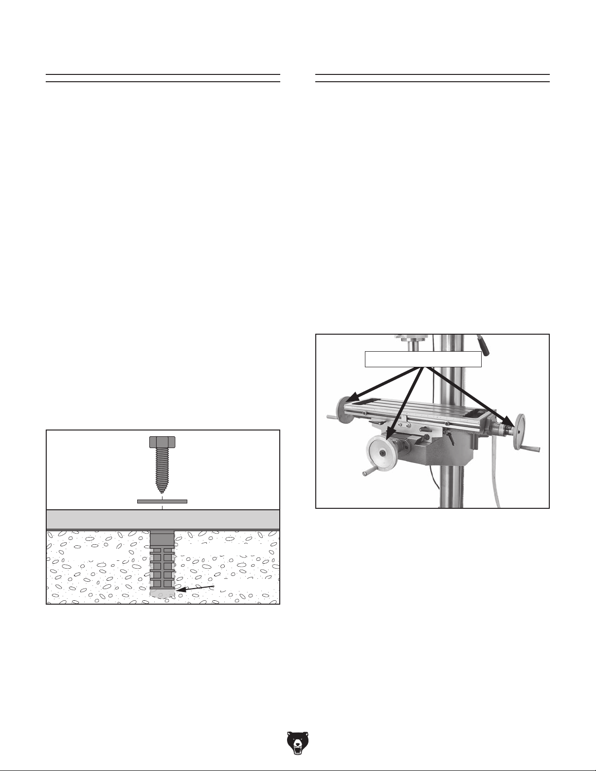
1. Install (1) handwheel (see Figure 8) on
Y-axis leadscrew shaft and (2) handwheels
on X-axis leadscrew shaft, then secure
handwheels with (3) M6-1 x 12 cap screws
and 6.5mm flat washers.
2. Thread (1) handle into each handwheel and
tighten to secure (see Figure 8).
Lag Screw
Machine Base
Concrete
Figure 7. Popular method for anchoring
machinery to a concrete floor.
-18-
Flat Washer
Lag Shield Anchor
Drilled Hole
Handles & Handwheels
Figure 8. Handwheel handles attached.
Model G0751 (Mfd. Since 07/15)
Page 21

Joining Drill Chuck
Lubricating Drill
& Arbor
An arbor is included for the drill chuck that
comes with this machine. The following procedure
describes how to install the arbor in the chuck.
After the arbor is installed in the drill chuck, it
is very difficult to separate the assembly. If you
would like to use a different chuck in the future,
we recommend obtaining a new arbor.
Important: DO NOT install the drill chuck and
arbor assembly into the spindle until AFTER the
test run.
To join the drill chuck and arbor:
1. Use acetone or lacquer thinner to clean drill
chuck and arbor mating surfaces, especially
the bore.
2. Retract chuck jaws completely into chuck.
3. Insert small end of arbor into chuck.
Press
GEARBOX MUST
BE FILLED WITH OIL!
OIL MAY NOT BE
SHIPPED WITH MACHINE!
Refer to Lubrication Section
for Correct Oil Type.
The headstock oil reservoir must be properly filled
with oil before the drill press can be operated for
the first time.
Damage caused by running the machine without
the proper amount of oil in the reservoir will not be
covered under warranty. Refer to the Lubrication
section, beginning on Page 33, for details on how
to check and add oil.
4. Hold assembly by the arbor and tap chuck
onto a block of wood with medium force, as
illustrated in Figure 9.
Figure 9. Tapping drill chuck/arbor on block of
wood.
5.
Attempt to separate drill chuck and arbor by
hand —if they separate, repeat Steps 3–4.
Model G0751 (Mfd. Since 07/15)
-19 -
Page 22

Before the machine can be connected to the
power source, an electrical circuit and connection device must be prepared per the POWER
SUPPLY section in this manual, and all previous setup instructions in this manual must be
complete to ensure that the machine has been
assembled and installed properly.
Power Connection
or equipment damage
not properly grounded
Once assembly is complete, test run the machine
to ensure it is properly connected to power and
safety components are functioning correctly.
If you find an unusual problem during the test run,
immediately stop the machine, disconnect it from
power, and fix the problem BEFORE operating the
machine again. The
table in the
SERVICE section of this manual can help.
DO NOT start machine until all preceding
setup instructions have been performed.
Operating an improperly set up machine
Serious injury or death can result from
Test Run
Troubleshooting
Electrocution, fire, shock,
may occur if machine is
and connected to power
supply.
Connecting Plug to Power Cord
To connect the plug to the power cord, install a
6-15 plug on the end of the power cord, per the
plug manufacturer's instructions. If no instructions were included, use the wiring diagram on
Page 49.
Note About Extension Cords: Using an incor-
rectly-sized extension cord may decrease the life
of electrical components on your machine. If you
must use an extension cord, refer to Extension
Cords on Page 12 for more information.
The Test Run consists of verifying the following:
1) The motor powers up and runs correctly, and 2)
the Emergency STOP safety feature is functioning
properly.
using this machine BEFORE understanding
its controls and related safety information.
DO NOT operate, or allow others to operate,
machine until the information is understood.
may result in malfunction or unexpected results that can lead to serious injury,
death, or machine/property damage.
-20-
Model G0751 (Mfd. Since 07/15)
Page 23

To test run the machine:
Push Emergency STOP button on control
1.
panel.
Rotate mode selection switch to the center
2.
OFF position to prevent unexpected spindle
rotation.
Rotate the auto-downfeed ON/OFF knob to
3.
OFF.
Rotate the auto-downfeed rate selector knob
4.
to OFF.
Fill coolant reservoir with coolant (refer to
5.
Coolant beginning on Page 38 for detailed
instructions).
Connect machine to power source by insert-
6.
ing power cord plug into matching receptacle—the power lamp should light after
connection.
Rotate mode selection switch to left (Drilling/
8.
Milling).
Push Spindle Forward button to start machine.
9.
A correctly operating machine runs smoothly
with little or no vibration or rubbing noises.
Press Emergency STOP button to stop
10.
machine.
WITHOUT resetting Emergency STOP but-
11.
ton, press Spindle Forward button—the
machine should not start.
—If the machine does start (with the
Emergency STOP button pushed in), immediately disconnect machine from power.
The Emergency STOP button safety fea-
ture is not working correctly. This safety
feature must work properly before proceeding with regular operations. Call Tech
Support for help.
Twist Emergency STOP button clockwise
7.
until it pops out—this resets the switch so the
machine can be started (see Figure 10).
I
S
W
T
T
To Reset
Switch...
Twist Button
Clockwise
OFF
Figure 10. Resetting the switch.
Reset Emergency STOP button.
12.
13. Position coolant nozzle over table, use cool-
ant switch on the control panel to turn coolant
pump ON, then open valve on base of nozzle
to test coolant system.
Turn coolant pump OFF.
14.
The Test Run is complete. Before beginning any
regular operations, perform the Spindle Break-In
procedure on the next page.
Model G0751 (Mfd. Since 07/15)
-21-
Page 24

Spindle Break-In
Before placing operational loads on the spindle,
complete this break-in procedure to fully distribute
lubrication throughout the bearings and ensure
trouble-free performance.
Failure to complete the spindle break-in
process may lead to premature failure of the
bearings—this will not be covered under
warranty.
To perform the spindle break-in procedure:
Make sure the spindle is completely stopped,
1.
then set spindle speed to 90 RPM (refer
to Setting Spindle Speed on Page 30 for
detailed instructions).
Inspections &
Adjustments
The following list of adjustments were performed
at the factory before the machine was shipped:
• Gib Adjustments ..............................Page 42
• Leadscrew Backlash
Adjustments .....................................Page 42
Return Spring Tension .................... Page 45
•
Be aware that machine components can shift
during the shipping process. Pay careful attention to these adjustments during operation of the
machine. If you find that the adjustments are not
set according to the procedures in this manual or
your personal preferences, re-adjust them.
Do not leave this machine unattended during
the Spindle Break-In procedure. If your
attention is needed elsewhere during this
procedure, stop the machine and restart the
procedure later from the beginning.
Run machine for a minimum of 10 minutes.
2.
3. Repeat Step 2 for each spindle speed, work-
ing to progressively higher speeds.
Note: If the machine is new, we recommend
changing the headstock oil while it is still warm
and any particles from the manufacturing process
are still in suspension (refer to Page 34 in the
Lubrication subsection for detailed instructions).
The spindle break-in is now complete!
-22-
Model G0751 (Mfd. Since 07/15)
Page 25

SECTION 4: OPERATIONS
The purpose of this overview is to provide the novice machine operator with a basic understanding
of how the machine is used during operation, so
the
discussed later
in this manual
Due to the generic nature of this overview, it is
not intended to be an instructional guide. To learn
more about specific operations, read this entire
manual,
training from experienced
machine operators
outside of this manual by reading "how-to" books,
trade magazines, or websites.
To reduce your risk of
serious injury, read this
entire manual BEFORE
Operation Overview
machine controls/components
are easier to understand.
To complete a typical operation, the operator
does the following:
1. Examines workpiece to make sure it is suit-
able for cutting.
Puts on protective gear.
2.
3. Securely clamps workpiece to table.
4. With machine disconnected from power,
installs correct cutting tool.
seek additional
, and do additional research
using machine.
To reduce risk of eye or face injury from
flying chips, always wear approved safety
glasses and a face shield when operating
this machine.
Adjusts headstock height above table.
5.
6. Checks range of table or spindle movement
to make sure setup is safe and correct for
operation.
Selects correct spindle speed.
7.
8. Connects machine to power and turns it ON.
Uses downfeed controls or table controls to
9.
perform cutting operation.
Turns machine OFF and waits for spindle to
10.
completely stop before removing workpiece.
When tilting the head and returning it back
to 90°, you will need to tram the spindle with
the table to ensure that it is set perfectly.
Refer to the Tramming Spindle section on
Page 43 for detailed instructions.
If you are not experienced with this type
of machine, WE STRONGLY RECOMMEND
that you seek additional training outside of
this manual. Read books/magazines or get
formal training before beginning any projects. Regardless of the content in this section, Grizzly Industrial will not be held liable
for accidents caused by lack of training.
Model G0751 (Mfd. Since 07/15)
-23-
Page 26

Headstock
Movement
The headstock travels up and down the column,
rotates around the column 180° in each direction,
and tilts 90° left and right relative to the table.
Raising/Lowering Headstock
Tool Needed Qty
Wrench 24mm ................................................... 1
Loosen the locking hex nuts shown in
Figure 11, then use the headstock Z-axis crank
(see Figure 12) to raise/lower the headstock.
Rotating Headstock
Tool Needed Qty
Wrench 24mm ................................................... 1
Loosen the locking hex nuts shown in Figure 11,
then slowly rotate the headstock around the column. Lock the headstock in place by retightening
the locking hex nuts before beginning operation to
avoid unexpected headstock movement.
Tilting Headstock
Tool Needed Qty
Wrench 22mm ................................................... 1
Loosen the three tilt locking hex nuts—one on
each side of the headstock (see Figure 13) and
one underneath the headstock (see Figure 14).
Locking
Hex Nut
(1 on each side)
Locking
Hex Nuts
Figure 11. Headstock locking hex nuts.
Headstock
Z-Axis
Crank
Figure 12. Headstock Z-axis crank location.
Lock the headstock in place by retightening the
locking hex nuts before beginning operation to
avoid unexpected headstock movement.
Figure 13. Headstock tilt locking hex nuts.
Locking
Hex Nut
(Underneath)
Figure 14. Headstock tilt hex nut underneath.
Slowly tilt the headstock to the desired angle, then
retighten the tilt locking hex nuts before beginning
operation to avoid unexpected headstock movement.
-24-
Model G0751 (Mfd. Since 07/15)
Page 27

Table Movement
F. Y-Axis Table Lock: Increases rigidity of
table when Y-axis movement is not required
for operation.
The table travels in the three axis paths (X-axis or
left to right, Y-axis or back and forth, and Z-axis
or up and down), and rotates around the column
180°.
X- & Y-Axis Table Travel
Use Figure 15 and the descriptions below to better understand the table components that control
X- and Y-axis travel.
A
B
C
H
G
D
F
E
G. X-Axis Table Locks: Increases rigidity of
table when X-axis movement is not required
for operation.
H. Y-Axis Handwheel: Moves table back and
forth.
Z-Axis Table Travel
Loosen the two locking handles shown in
Figure 16, then rotate the table Z-axis crank to
raise/lower the table.
Locking Handles
Crank
Figure 15. X- and Y-axis table travel controls.
A. X-Axis Handwheel: Moves table left and
right.
B. X-Axis Limit Stops: Adjustable along front
of table to restrict X-axis table movement.
Limit Stop Block: Stops X-axis table travel
C.
when contacted by a limit stop.
D. X-Axis Table Scale: Displays table position
left or right from center.
E. Graduated Dial: Displays table travel in
increments of 0.001". One full revolution
equals 0.100" of travel. The thumb screw can
be used to adjust the dial to "0" for relative
table position.
Figure 16. Z-axis table controls.
Retighten the locking handles before beginning
operation to avoid unexpected table movement.
Rotating Table
Loosen the two locking handles shown in
Figure 16, then slowly rotate the table around
the column. Retighten the locking handles before
beginning operation to avoid unexpected table
movement.
Model G0751 (Mfd. Since 07/15)
-25-
Page 28

Downfeed
The Model G0751 features four ways to control
spindle downfeed:
• Coarse Downfeed
• Fine Downfeed
• Auto-Downfeed
• Tapping Downfeed
Downfeed Controls
Use Figure 17 and the descriptions below to identify the downfeed controls that are referred to in
the following procedures.
Coarse Downfeed
Use the coarse downfeed handles to control
spindle travel in rapid, large amounts for milling/
drilling.
To use coarse downfeed:
Make sure spindle is completely stopped.
1.
2. Loosen depth graduated dial lock handle (G).
Rotate depth graduated dial (H) to limit
3.
downfeed depth, then retighten lock handle.
Rotate auto-downfeed ON/OFF knob (A) and
4.
auto-downfeed rate selector knob (B) counterclockwise to OFF positions.
A
B
J
H
G
I
F
Figure 17. Identification of downfeed controls.
A. Auto-Downfeed ON/OFF Knob
B. Auto-Downfeed Rate Selector Knob
Tapping Limit Stops
C.
D. Tapping Limit Switches
E. Coarse Handle Lock-Down Thumb Screw
F. Coarse Downfeed Handle
G. Depth Graduated Dial Lock Handle
H. Depth Graduated Dial
I. Fine Downfeed Graduated Dial
C
D
E
Push coarse downfeed handles (F) toward
5.
headstock and tighten coarse handle lockdown thumb screw (E) to hold them in place.
Rotate mode selection switch on control
6.
panel to Drilling/Milling position.
Start spindle rotation and use coarse
7.
downfeed handles to control spindle travel.
Fine Downfeed
Use the fine downfeed handwheel to control
spindle travel in slow, small amounts for milling/
drilling.
To use fine downfeed:
Make sure spindle is completely stopped.
1.
2. Loosen depth graduated dial lock handle (G).
Loosen coarse handle lock-down thumb
3.
screw (E) and pull coarse downfeed handles
(F) away from headstock.
Rotate auto-downfeed ON/OFF knob (A) and
4.
auto-downfeed rate selector knob (B) counterclockwise to OFF positions.
Rotate depth graduated dial (H) to limit
5.
downfeed depth, then retighten lock handle.
J. Fine Downfeed Handwheel
-26-
Model G0751 (Mfd. Since 07/15)
Page 29

6. Rotate mode selection switch on control
panel to Drilling/Milling position.
Start spindle rotation and use fine downfeed
7.
handwheel (J) to control spindle travel.
Tapping Downfeed
Tapping downfeed allows the downward spiraling
of the tap to control spindle travel. The depth is
controlled by adjusting the tapping limit stops (C)
in relation with the tapping limit switches (D).
Note: Use the fine downfeed graduated dial
(I) and the attached thumb screw to measure
the relative amount of spindle travel.
Auto-Downfeed
The auto-downfeed feature uses headstock gears
to control powered downfeed in rates of 0.004,
0.007, and 0.010 inches per spindle revolution.
To use auto-downfeed:
Make sure spindle is completely stopped.
1.
2. Loosen depth graduated dial lock handle (G).
This will disengage depth graduated dial from
the operation.
Rotate auto-downfeed ON/OFF knob (A) to
3.
ON position.
Rotate auto-downfeed rate selector knob (B)
4.
clockwise to desired downfeed rate.
5. Loosen coarse handle lock-down thumb
screw (E) and pull coarse downfeed handles
(F) away from headstock.
Rotate mode selection switch on control
6.
panel to Drilling/Milling position.
To use tapping downfeed:
Make sure spindle is completely stopped.
1.
2. Rotate the auto-downfeed ON/OFF and auto-
downfeed rate selector knobs to the OFF
position.
Adjust depth graduated dial (H) to allow for
3.
maximum spindle travel and tighten depth
graduated dial lock handle (G) to secure it.
Push coarse downfeed handles (F) toward
4.
headstock and tighten coarse handle lockdown thumb screw (E) to hold them in place.
Use a 5mm hex wrench to adjust tapping limit
5.
stops (C) in relation to tapping limit switches
(D).
— The shorter limit stop is used to reverse
spindle rotation when desired depth is
reached. This will happen when this limit
stop contacts outer limit switch.
— The longer limit stop is used to stop spindle
rotation for repetitive operations. This will
happen when this limit stop contacts inner
limit switch. Adjust limit stop in relation to
inner limit switch so that spindle rotation
stops when the tap is no longer engaged
with workpiece.
When using auto-downfeed, the spindle will
not automatically stop or reverse when it
reaches the bottom depth of travel. To avoid
machine damage, manually stop spindle
rotation before this happens.
7. Start spindle forward rotation to engage the
auto-downfeed.
When desired depth of spindle travel is
8.
reached, stop spindle travel.
Push coarse downfeed handles toward head-
9.
stock and use them to return spindle to top.
Model G0751 (Mfd. Since 07/15)
Rotate mode selection switch on control
6.
panel to Tapping position.
Note: Position tap just slightly above the
workpiece when the spindle is at the top most
position. This will prevent the tap breaking
when spindle rotation is started.
Start spindle forward rotation.
7.
8. Use coarse downfeed handles to slowly lower
tap into workpiece until it engages workpiece
and the downward spiraling action of tap
controls spindle travel, then release manual
pressure on coarse downfeed handles.
-27-
Page 30

Depth Digital Display
The depth digital display on the headstock displays the relative spindle depth.
Use Figure 18 and the following descriptions to
gain an understanding of the display controls.
Installing/Removing
Tooling
The Model G0751 includes the following spindle
tools (see Figure 19):
. B16 Drill Chuck w/R-8 Arbor: Use with drill
A
bits.
A
F
E
D
Figure 18. Depth digital display controls.
A. OFF Button
B. ON/0 Button: Turns display ON. When the
display is ON, zeros the display.
C. Battery Compartment: Holds the CR2032
3V lithium cell battery that powers the unit.
B
C
. R-8–MT#3 Spindle Sleeve: Use with MT#3
B
tooling with or without a tang. Has a drift key
slot for tool removal.
. MT#3–MT#2 Spindle Sleeve: Use with the
C
R-8–MT#3 spindle sleeve for MT#2 tooling.
Has a drift key slot for tool removal.
Alignment Slot
A
Drift Key Slot
C
B
D. Up/Down Buttons: Adjusts the display read-
ing when pressed.
E. In/mm Button: Alternates the display
between inch and millimeter measurements.
F. LED Digital Display
-28-
Figure 19. Drill chuck and arbors included with
Model G0751.
Cutting tools are sharp and
can easily cause laceration
injuries. Always protect
your hands with leather
gloves or shop rags when
handling cutting tools.
Model G0751 (Mfd. Since 07/15)
Page 31

Installing Tooling
Tool Needed Qty
Wrench 19mm ................................................... 1
To install tooling:
DISCONNECT MACHINE FROM POWER!
1.
2. Remove drawbar cap as shown in Figure 20.
Drawbar
Drawbar Cap
Adjustment
Nut
Removing Tooling
Tools Needed Qty
Wrench 19mm ................................................... 1
Brass or Dead Blow Hammer
To remove tooling:
DISCONNECT MACHINE FROM POWER!
1.
2. Remove drawbar cap, and only unthread
drawbar from tooling one full rotation.
Note: Do not fully unthread tooling from
drawbar, or drawbar and tooling threads
could be damaged during the next step.
Tap top of drawbar with hammer to unseat
3.
taper.
Hold onto tooling with one hand and fully
4.
unthread drawbar with the other hand.
............................ 1
Figure 20. Drawbar components.
Align tooling alignment slot (see Figure 19)
3.
with pin inside spindle, then insert tooling into
spindle until it contacts drawbar.
Note: Drawbar height inside spindle can be
changed by rotating the adjustment nut (see
Figure 20).
Working from the top, hand-thread drawbar
4.
into tooling until snug, then use a 19mm
wrench to tighten it.
Note: DO NOT overtighten drawbar.
Overtightening makes tooling removal difficult and could damage arbor and drawbar
threads.
Re-install drawbar cap.
5.
Model G0751 (Mfd. Since 07/15)
-29-
Page 32

Spindle Speed
Using the correct spindle speed is important for
safe and satisfactory results, as well as maximizing tool life.
To set the spindle speed for your operation, you
will need to: 1) Determine the best spindle speed
for the operation, and 2) configure the spindle
speed levers to produce the required spindle
speed.
Determining Spindle Speed
Many variables affect the optimum spindle speed
to use for any given operation, but the two most
important are the recommended cutting speed
for the workpiece material and the diameter of
the cutting tool, as noted in the formula shown in
Figure 21.
Setting Spindle Speed
The chart below explains how to position the
spindle range and speed levers to set the desired
spindle speed.
Spindle Speed Range Lever Speed Lever
90 RPM L 1
210 RPM L 2
345 RPM L 3
670 RPM H 1
118 0 R P M H 2
1970 RPM H 3
Change spindle speed ONLY when the
spindle is completely stopped. Otherwise,
machine damage could occur.
*Recommended
Cutting Speed (FPM) x 12
Tool Dia. (in inches) x 3.14
Spindle
=
Speed
(RPM)
*Double if using carbide cutting tool
Figure 21. Spindle speed formula for mill/drills.
Cutting speed, typically defined in feet per minute
(FPM), is the speed at which the edge of a tool
moves across the material surface.
A recommended cutting speed is an ideal speed
for cutting a type of material in order to produce
the desired finish and optimize tool life.
The books Machinery’s Handbook or Machine
Shop Practice, and some internet sites, provide excellent recommendations for which cutting
speeds to use when calculating the spindle speed.
These sources also provide a wealth of additional
information about the variables that affect cutting
speed and they are a good educational resource.
With the spindle completely stopped, position the
spindle range and speed levers (see Figure 22)
to set the spindle speed.
Note: If the levers will not move to the desired
position, rotate the spindle by hand while applying
pressure on the lever. When the gear teeth align,
the lever will move into place.
Speed
Lever
Spindle Speed Chart
Range
Lever
Figure 22. Spindle speed controls.
Also, there are a large number of easy-to-use
spindle speed calculators that can be found on
the internet. These sources will help you take into
account the applicable variables in order to determine the best spindle speed for the operation.
-30-
Model G0751 (Mfd. Since 07/15)
Page 33

SECTION 5: ACCESSORIES
Installing unapproved accessories may
order online at www.grizzly.com or call 1-800-523-4777
cause machine to malfunction, resulting in
serious personal injury or machine damage.
To reduce this risk, only install accessories
recommended for this machine by Grizzly.
T23962—ISO 68 Moly-D Way Oil, 5 gal.
T23963—ISO 32 Moly-D Machine Oil, 5 gal.
Moly-D oils are some of the best we've found for
maintaining the critical components of machinery
because they tend to resist run-off and maintain
their lubricity under a variety of conditions—as
well as reduce chatter or slip. Buy in bulk and
save with 5-gallon quantities.
NOTICE
Refer to our website or latest catalog for
additional recommended accessories.
T26485—58-Pc. Clamping Kit for 7⁄16" T-Slots
This clamping kit includes 24 studs, 6 step block
pairs, 6 T-nuts, 6 flange nuts, 4 coupling nuts, and
6 end hold-downs. The rack is slotted so it can be
mounted close to the machine for easy access.
Figure 23. T26485 58-Pc. Clamping Kit.
T23962
Figure 25. ISO 68 and ISO 32 machine oil.
H7617—High-Pressure Oil Can with Flexible
Nozzle
Whether you are lubricating cutting tools or maintaining machinery in top operating condition, you
will appreciate these High Pressure Oil Cans.
Each can holds 5 ounces of oil and has a triggeractivated, high-pressure pump.
T23963
G7066—5" Tilting/Swiveling Milling Vise
H7576—Precision Self-Centering Vise
G7066
Figure 26. Model H7617 High Pressure Oil Can.
H7576
Model G0751 (Mfd. Since 07/15)
Figure 24. Specialty milling vises.
-31-
Page 34

order online at www.grizzly.com or call 1-800-523-4777
H7847— 78-Pc. HSS Tap & Die Set
This is the best and one of the most complete
Tap and Die sets on the market today. Includes
2 die handles, 2 standard tap handles, 2 Tee tap
handles, screwdriver and pitch gauge. All taps are
taper grounds and all dies are adjustable. Sizes
include four 4-40 taps and four dies, six 6-32 taps
and three dies, two 8-32 a2 taps and two dies and
1
one each: 10-24, 10-32, 12-24, 12-28,
5
⁄16"-18 , 5⁄16"-24, 3⁄8"-16 , 3⁄8"-24, 7⁄16"-14, 7⁄16"-20,
28,
1
⁄2 "-13 , 1⁄2 "-20, 9⁄16"-12, 9⁄16"-18 , 5⁄8"-11, 5⁄8"-18 , 3⁄4"-10,
3
⁄4"-16, 7⁄8"-9, 7⁄8"-14, 1"-8 and 1"-12 taps and dies.
⁄4"-20, 1⁄4"-
Case Included.
T24799—1-2-3 Block Set
G9815—Parallel Set
Blocks are square to within .0003". Measure 1" x
1
2" x 3". Parallel set measures 6" long by
3
⁄4", 7⁄8", 1", 11⁄8", 11⁄4", 11⁄8", 13⁄8", 11⁄2 ", and 15⁄8".
⁄2 ", 5⁄8",
Figure 29. T24799 1-2-3 Block Set and G9815
Parallel Set.
H5930—4-Pc. Center Drill Set 60°
H5931—4-Pc. Center Drill Set 82°
Double ended HSS Center Drills are precision
ground. Includes sizes 1-4.
Figure 27. H7847 78-Pc. Tap & Die Set.
G9612—Test Indicator
This Test Indicator has a 0.03" range in graduations of 0.0005", an easy-to-read dial, and a
pivoting stylus that moves at right angles to the
dial face.
Figure 28. G9612 Test Indicator.
Figure 30. 4-Pc. Center Drill Sets.
G3658—Titanium Drill Bits
Titanium nitride-coated bits last up to six times as
long as uncoated bits. This 115-piece set features
1
29 fractional bits, from
1
⁄64", letter bits from A–Z, and 60 number bits.
of
⁄6" to 1⁄2 " in increments
Housed in rugged steel case.
Figure 31. G3658 Titanium Drill Bits.
-32-
Model G0751 (Mfd. Since 07/15)
Page 35

SECTION 6: MAINTENANCE
To reduce risk of shock or
accidental startup, always
disconnect machine from
power before adjustments,
maintenance, or service.
Schedule
For optimum performance from this machine, this
maintenance schedule must be strictly followed.
Daily:
• Check/repair loose mounting bolts.
• Check/replace damaged tooling.
Check/repair worn or damaged wires.
•
Clean debris and built up grime off of machine.
•
Check/resolve any other unsafe condition.
•
Cleaning &
Protecting
Metal chips left on the machine will invite oxidation and a gummy residue build-up around the
moving parts. Use a brush and shop vacuum to
remove chips and debris from the working surfaces of the mill/drill. Never blow off the mill/drill
with compressed air, as this will force metal chips
deep into the mechanisms and may cause injury
to yourself or bystanders.
Remove any rust build-up from unpainted cast
iron surfaces of your mill/drill and treat with a nonstaining lubricant after cleaning.
Keep unpainted cast iron surfaces rust-free with
regular applications of ISO 68 way oil (see
Page 31 for offerings from Grizzly).
Every 8 Hours of Operation:
• Check/add headstock oil (Page 34).
Lubricate table ball oilers (Page 35).
•
• Lubricate dovetail ways (Page 35).
• Lubricate downfeed gears (Page 36).
• Check/add coolant (Page 38).
Every 40 Hours of Operation:
• Lubricate quill and column surfaces (Page 36).
Lubricate table leadscrews (Page 37).
•
Every 90 Days of Operation:
Lubricate quill rack and pinion (Page 37).
•
• Lubricate column racks (Page 38).
• Change coolant (Page 38).
Bi-Annually:
Lubricate spindle spline (Page 36).
•
Annually:
Change headstock oil (Page 36).
•
Model G0751 (Mfd. Since 07/15)
Lubrication
An essential part of lubrication is cleaning the
components before lubricating them.
This step is critical because grime and chips build
up on lubricated components, which makes them
hard to move. Simply adding more lubricant will
not result in smooth moving parts.
Clean all exterior components in this section with
mineral spirits, shop rags, and brushes before
lubricating.
DISCONNECT MACHINE FROM POWER
BEFORE PERFORMING LUBRICATION.
NOTICE
Follow reasonable lubrication practices as
outlined in this manual. Failure to do so
could lead to premature failure of your
machine and will void the warranty.
-33-
Page 36

Headstock Reservoir
Oil Ty p e ......Model T23962 or ISO 68 Equivalent
Oil Amount
Check/Add Frequency
Change Frequency
The headstock has the proper amount of oil when
the sight glass is halfway full (see Figure 32).
................................................ 3 1⁄4 Qt.
...........8 Hrs. of Operation
................................ Annually
Place a 1-gallon or larger drain pan on the
4.
table under the headstock.
Remove the drain plug (see Figure 33) from
5.
underneath the headstock. Allow the oil to
completely drain into the pan.
Drain
Plug
Fill
Plug
Figure 32. Headstock sight glass.
Tool Needed Qty
Hex Wrench 8mm .............................................. 1
To change the headstock oil:
Run the spindle at 670 RPM for approximate-
1.
ly 10 minutes to warm the oil.
DISCONNECT MACHINE FROM POWER!
2.
3. Remove the fill plug (see Figure 32).
Sight
Glass
Figure 33. Headstock drain plug
(headstock tilted 90° for clarity).
Follow federal, state, and local requirements for proper disposal of used oil.
6. Replace the drain plug.
7. Add oil until the sight glass is halfway full,
then replace the fill plug.
Clean up any spilled oil to prevent slipping
8.
hazards.
-34-
Model G0751 (Mfd. Since 07/15)
Page 37

Table Ball Oilers
Oil Ty p e ......Model T23963 or ISO 32 Equivalent
Oil Amount
Lubrication Frequency
......................................... 1–2 Pumps
...........8 Hrs. of Operation
Dovetail Ways
Oil Ty p e ......Model T23962 or ISO 68 Equivalent
Oil Amount
Lubrication Frequency
............................................Thin Coat
...........8 Hrs. of Operation
Proper lubrication of the three table ball oilers
(shown in Figure 34) is done with a pump-type oil
can that has a plastic or rubberized cone tip (see
Page 31 for offerings from Grizzly). We do not
recommend using metal needle or lance tips, as
they can push the ball too far into the oiler, break
the spring seat, and lodge the ball in the oil galley.
Figure 34. Table ball oiler locations.
Use the table controls to access the entire length
of the dovetail ways (see Figure 35), then clean
them with mineral spirits and shop rags.
Note: The table and saddle each have two opposing ways.
Table
Dovetail
Saddle Dovetail Way
(1 of 2)
Figure 35. Dovetail way locations.
Way
(1 of 2)
Push the tip of the oil can nozzle against the ball
oiler to create a hydraulic seal, then pump the oil
can once or twice. If you see sludge and contaminants coming out of the lubrication area, continue
pumping the oil can until the oil runs clear. When
finished, wipe away the excess oil.
When dry, apply a thin coat of oil to the surfaces.
Move each component through the entire path of
travel to distribute the lubricant.
Model G0751 (Mfd. Since 07/15)
-35-
Page 38

Downfeed Gears
Oil Ty p e ......Model T23963 or ISO 32 Equivalent
Oil Amount
Lubrication Frequency
......................................... Fill Oil Cup
...........8 Hrs. of Operation
Quill & Column Surfaces
Oil Ty p e ......Model T23962 or ISO 68 Equivalent
Oil Amount
Lubrication Frequency
............................................Thin Coat
...........8 Hrs. of Operation
Lift the oil cup cap (see Figure 36) to fill the cup
with oil. The oil will slowly drain into the downfeed
gears over time.
Oil Cup
Figure 36. Downfeed gears oil cup location.
Spindle Spline
Grease Type ......... NLGI#2 Grease or Equivalent
Grease Amount
Lubrication Frequency
.............................Small Amount
....................... Bi-Annually
Use the controls to access the entire smooth
surfaces of the quill and column (see Figures
38– 39), then clean them with mineral spirits and
shop rags.
Note: Avoid removing the grease from the column
racks during cleaning.
Quill
Surface
Figure 38. Quill surface location.
Remove the drawbar cap (see Figure 37) to
expose the spindle spline.
Drawbar
Cap
Spindle
Spline
Figure 37. Spindle spline location.
Use the coarse downfeed handles to lower the
spindle, then apply a small amount of grease
inside the resulting hole. Run the spindle up and
down several times to distribute the grease.
Column
Surfaces
Figure 39. Column surface locations.
When dry, apply a thin coat of oil to the surfaces.
Move the components through the entire path of
travel to distribute the lubricant.
-36-
Model G0751 (Mfd. Since 07/15)
Page 39

Table Leadscrews
Oil Ty p e ......Model T23962 or ISO 68 Equivalent
Oil Amount
Lubrication Frequency
............................................Thin Coat
.........40 Hrs. of Operation
Quill Rack & Pinion
Grease Type ......... NLGI#2 Grease or Equivalent
Grease Amount
Lubrication Frequency
....................................Thin Coat
......... 90 hrs. of Operation
Move the table as necessary to access the entire
length of the X- and Y-axis leadscrews (see
Figures 40–41), then use mineral spirits, shop
rags, and a brush to clean them.
X-Axis Leadscrew
Figure 40. X-axis leadscrew location.
Y-Axis
Leadscrew
Move the quill up and down to gain full access
to the quill rack and pinion (see Figure 42), then
clean the teeth with mineral spirits, shop rags, and
a brush.
Pinion
Rack
Figure 42. Quill rack and pinion locations.
When dry, use a brush to apply a thin coat of
grease to the teeth, then raise/lower the quill to
distribute the grease.
Figure 41. Y-axis leadscrew location.
Use a clean brush to apply a thin coat of oil to the
leadscrew threads, then move the table through
the X- and Y-axis paths to distribute the oil.
Note: Re-apply oil to the quill smooth outside
surface that was removed during the cleaning
process.
Model G0751 (Mfd. Since 07/15)
-37-
Page 40

Column Racks
Grease Type ......... NLGI#2 Grease or Equivalent
Grease Amount
Lubrication Frequency
Move the headstock and table up and down to
gain full access to the column racks (see Figures
43–44), then clean the teeth with mineral spirits,
shop rags, and a brush.
Figure 43. Column lower rack location.
....................................Thin Coat
......... 90 hrs. of Operation
Column
Lower Rack
Coolant
Hazards
As some coolant ages, dangerous microbes can
proliferate and create a biological hazard. The risk
of exposure to this hazard can be greatly reduced
by checking the coolant regularly, as indicated in
the maintenance schedule.
The important thing to keep in mind when working
with the coolant is to minimize exposure to your
skin, eyes, and respiratory system by wearing
the proper PPE (personal protective equipment),
such as splash-resistant safety glasses, longsleeve gloves, protective clothing, and a NIOSH
approved respirator.
BIOLOGICAL & POISON
HAZARD!
Use the correct personal
protection equipment when
handling coolant. Follow
federal, state, and fluid
manufacturer requirements
for proper disposal.
Column
Upper Rack
Figure 44. Column upper rack location.
When dry, use a brush to apply a thin coat of
grease to the teeth, then raise/lower the headstock and table to distribute the grease.
Note: Re-apply oil to the column smooth surfaces
that was removed during the cleaning process.
A small amount of coolant is lost during normal
operation. Check the coolant reservoir regularly
and fill it if necessary. We recommend changing the coolant every three months or sooner if it
develops an unpleasant odor. However, be sure
to follow the coolant manufacturer's instructions
when checking, adding, or changing coolant.
The coolant reservoir holds approximately 2 gallons (7 1⁄2 liters) of fluid.
Running the coolant pump without adequate coolant in the reservoir may permanently damage the coolant pump, which will
not covered by the warranty.
-38-
Model G0751 (Mfd. Since 07/15)
Page 41

Checking/Adding Coolant
Tool Needed Qty
Hex Wrench 5mm .............................................. 1
To check/add coolant:
1. DISCONNECT MILL FROM POWER!
Remove coolant pump from base (see
2.
Figure 45).
Changing Coolant
Tools Needed Qty
Hex Wrench 5mm .............................................. 1
Catch Pan
Empty Bucket 5 Gal........................................... 1
New Coolant
To change the coolant:
Put on personal protective equipment.
1.
2. Place catch pan on table, position the coolant
nozzle into pan, then use coolant pump to
drain reservoir.
.......................................................... 1
........................... Approx. 2 Gallons
Coolant
Pump
Figure 45. Coolant pump removed from base.
Use a clean metal tool as a dip stick to mea-
3.
sure level of coolant in the reservoir. If level
is lower than 2", add coolant.
Note: Clean away debris and grime from
pump bottom screen before replacing it.
Re-install coolant pump before resuming
4.
operations.
Note: When catch pan is near full, empty it
into 5 gallon bucket, then repeat process.
DISCONNECT MACHINE FROM POWER!
3.
4. Remove coolant pump and move it away.
5. Thoroughly clean bottom of reservoir and
pump bottom screen. Make sure interior is
completely dry before adding new coolant.
Note: Use a cleaning solution that is compat-
ible with type of coolant. For instance, if you
are using a water-based coolant, then use a
water-based cleaning solvent.
When reservoir and pump are clean and dry,
6.
re-fill the reservoir, and replace pump.
Tip: Place a couple of magnets inside res-
ervoir under return hose to collect metal particles to keep them out of coolant pump.
Model G0751 (Mfd. Since 07/15)
-39-
Page 42

Review the troubleshooting procedures in this section if a problem develops with your machine. If you need
the
serial number and manufacture date of your machine before calling.
SECTION 7: SERVICE
replacement parts or additional help with a procedure, call our Technical Support. Note: Please gather
Troubleshooting
Motor & Electrical
Symptom Possible Cause Possible Solution
Machine does not
start.
Machine stalls or is
overloaded.
Machine has
vibration or noisy
operation.
1. Emergency stop button depressed.
2. Plug at fault or wired incorrectly.
3. Incorrect power supply voltage.
4. Wall fuse/circuit breaker is blown/tripped.
5. Wiring is open/has high resistance.
6. Motor wired incorrectly.
7. Control panel buttons at fault.
8. Motor or motor components are at fault.
1. Feed rate/cutting speed too fast.
2. Wrong cutter type.
3. Machine is undersized for the task or
tooling is incorrect for the task.
4. Motor has overheated.
5. Motor wired incorrectly.
6. Motor bearings are at fault.
7. Motor or motor components are at fault.
1. Motor or machine component is loose.
2. Workpiece not secure.
3. Excessive depth of cut.
4. Cutter/tooling is loose.
5. Cutter is dull or at fault.
6. Bit is chattering.
7. Machine is incorrectly anchored to floor or
sits unevenly.
8. Motor fan is rubbing on fan cover.
9. Motor bearings are at fault.
1. Twist emergency stop button clockwise until it pops
out to reset it.
2. Ensure plug is not damaged and is wired correctly.
3. Ensure power supply voltage matches circuit
requirements (Page 11).
4. Ensure circuit size is correct and a short does not
exist. Reset breaker or replace fuse.
5. Check for broken wires or disconnected/corroded
connections; repair/replace as necessary.
6. Ensure motor wiring is correct (Page 49).
7. Ensure each button is wired correctly; replace if at
fault (Page 48).
8. Test/repair/replace.
1. Decrease feed rate/cutting speed.
2. Use the correct cutter for the task.
3. Use smaller or sharper tooling; reduce feed rate or
spindle speed; use cutting fluid if possible.
4. Clean off motor, let cool, and reduce workload.
5. Ensure motor wiring is correct (Page 49).
6. Test by rotating shaft; rotational grinding/loose shaft
requires bearing replacement.
7. Test/repair/replace motor.
1. Inspect/replace stripped or damaged bolts/nuts, and
retighten with thread locking fluid.
2. Properly clamp workpiece on table or in vise.
3. Decrease depth of cut.
4. Make sure tooling is properly secured.
5. Replace/resharpen cutter.
6. Replace/sharpen bit; index bit to workpiece; use
appropriate feed rate and cutting RPM.
7. Tighten/replace anchor bolts; relocate/shim
machine.
8. Replace dented fan cover or damaged fan.
9. Test by rotating shaft; rotational grinding/loose shaft
requires bearing replacement.
-40-
Model G0751 (Mfd. Since 07/15)
Page 43

Operations
Symptom Possible Cause Possible Solution
Tool loose in spindle. 1. Tool is not fully drawn up into
spindle taper.
2. Debris on tool or in spindle taper.
3. Taking too big of a cut.
Breaking tools or cutters. 1. Spindle speed/feed rate is too fast.
2. Auto-downfeed rate is too fast.
3. Cutting tool too small.
4. Cutting tool getting too hot.
5. Taking too big of a cut.
6. Spindle extended too far down.
Workpiece vibrates or
chatters during operation.
Table is hard to move.
Bad surface finish.
Cutting/drilling results not
square.
1. Table locks not tight.
2. Workpiece not secure.
3. Spindle speed/feed rate is too fast.
4. Spindle extended too far down.
1. Table locks are tightened down.
2. Chips have loaded up on ways.
3. Dovetail ways are dry and need
lubrication.
4. Table limit stops are interfering.
5. Gibs are too tight.
1. Spindle speed/feed rate is too fast.
2. Using a dull or incorrect cutting tool.
3. Wrong rotation of cutting tool.
4. Workpiece not secure.
5. Spindle extended too far down.
1. Table and spindle are not at 90° to
each other.
1. Tighten draw bar.
2. Clean collet and spindle taper.
3. Lessen depth of cut and allow chips to clear.
1. Set spindle speed correctly (Page 30) or use slower
feed rate.
2. Use a slower auto-downfeed rate (Page 27).
3. Use larger cutting tool and slower feed rate.
4. Use coolant fluid or oil for appropriate application.
5. Incrementally increase the size of the bit until proper
diameter is reached.
6. Fully retract spindle and lower headstock. This
increases rigidity.
1. Tighten down table locks.
2. Properly clamp workpiece on table or in vise.
3. Set spindle speed correctly (Page 30) or use a
slower feed rate.
4. Fully retract spindle and lower headstock. This
increases rigidity.
1. Make sure table locks are fully released.
2. Frequently clean away chips that load up during
operations.
3. Lubricate dovetail ways (Page 35).
4. Check to make sure that all table limit stops are not
in the way.
5. Adjust gibs (see Page 42).
1. Set spindle speed correctly (Page 30) or use a
slower feed rate.
2. Sharpen cutting tool or select one that better suits
the operation.
3. Check for proper cutting rotation for cutting tool.
4. Properly clamp workpiece on table or in vise.
5. Fully retract spindle and lower headstock. This
increases rigidity.
1. Tram the spindle (Page 43).
Model G0751 (Mfd. Since 07/15)
-41-
Page 44

Adjusting Gibs
Gibs are tapered lengths of metal that are sandwiched between two moving surfaces. Gibs control the gap between these surfaces and how they
slide past one another. Correctly adjusting the
gibs is critical to producing good results.
Correctly positioning gibs is a matter of trial and
error and patience. Tight gibs make table movement more accurate but stiff. Loose gibs make
table movement sloppy but easier to do. The goal
of gib adjustment is to remove unnecessary sloppiness without causing the ways to bind.
Many experienced machinists adjust the gibs just
to the point where they can feel a slight drag in
table movement.
Screws on each end of the gib allow gib adjustment to increase or decrease the friction between
the sliding surfaces.
DISCONNECT MACHINE FROM POWER
BEFORE ADJUSTING THE GIBS!
Adjusting Leadscrew
Backlash
Leadscrew backlash is the amount of freeplay
movement in the leadscrew (when the leadscrew
moves but the table does not) after changing the
direction of rotation.
Leadscrews must have a certain amount of backlash to rotate easily, but it increases with wear
over time. Generally, 0.003"–0.006" leadscrew
backlash is acceptable to ensure smooth movement and reduce the risk of premature thread
wear.
The X- and Y-axis leadscrew backlash is adjusted using a long 4mm hex wrench to tighten/
loosen the cap screw on the leadscrew nut. This
adjusts the force the leadscrew nut exerts on the
leadscrew threads.
The X-axis leadscrew nut shown in Figure 47
is accessed from underneath the left side of the
table.
Make sure all table locks are loose. Then, loosen
one gib adjustment screw (see Figure 46) and
tighten the opposing screw the same amount to
move the gib, while at the same time rotating the
handwheel to move the table until you feel a slight
drag in that path of movement.
X-Axis Gib Screw
(1 of 2)
Y-Axis Gib Screw
(1 of 2)
Figure 46. Table gib screw locations.
The Y-axis leadscrew nut is similar and is accessed
from underneath the knee.
X-Axis Leadscrew Nut
Cap Screw
Figure 47. Location of X-axis leadscrew nut for
adjusting backlash.
-42-
Model G0751 (Mfd. Since 07/15)
Page 45
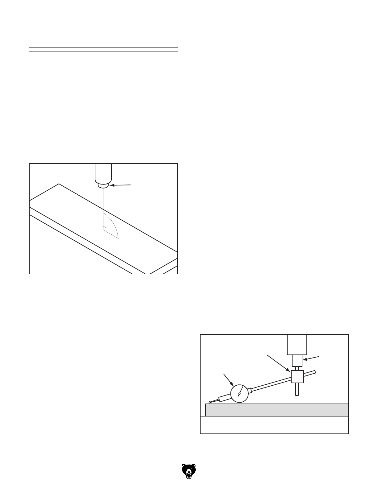
Tramming Spindle
When the operation requires that the spindle
axis be precisely perpendicular to the table, the
spindle must be trammed with the table. Simply
adjusting the headstock tilt to the 90° mark on
the tilt scale will not be precise enough for highly
accurate results.
Tools Needed Qty
Dial Indicator (with at least 0.0005" resolution) . 1
Indicator Holder (mounted on quill/spindle)
Precision Parallel Block (1-2-3 Blocks)
Note: A precision-ground plate can be substituted
for the parallel block. The farther the indicator
point can be placed from the spindle axis, the
more accurate the alignment measurements will
be.
....... 1
.............. 1
This procedure involves mounting a dial indicator
to the quill or spindle, rotating it around the table,
and adjusting the head position so that the spindle
axis is 90° to the table X-axis, as illustrated in
Figure 48.
Spindle
Table
Figure 48. Spindle centerline properly trammed
to the table.
Note: Keep in mind that the top surface of your
workpiece will likely not be parallel with the table
top. Depending on your operation, you may
choose to tram the spindle to the top surface of
the workpiece after it is mounted instead of tramming to the table.
Z-Axis
90º
X-Axis
To tram the spindle with the table:
DISCONNECT MACHINE FROM POWER!
1.
2. Prepare machine by performing the following
tasks:
— Stone table to remove all nicks and burrs,
then clean off all debris. Verify table is
clean by running your hand over the top of
it.
— Position table for the operation you intend
to perform after tramming—preferably centered with saddle.
— Tighten any table locks that should be tight
during intended milling operation.
Place parallel block underneath spindle.
3.
4. Install indicator holder into spindle or onto
quill, then mount indicator onto it so that
the point is as parallel to the block as possible (see the illustration in Figure 49 for an
example).
Indicator
Holder
Spindle
Model G0751 (Mfd. Since 07/15)
Dial Indicator
Parallel Block
Table
Figure 49. Dial indicator mounted.
-43-
Page 46

5. Place the parallel block directly under spindle
and indicator across length of table, as illustrated in Figure 50.
7.
Rotate spindle so that the indicator point
rests in the same manner on other end of
block, then read dial.
Note: If you must reposition quill to accom-
modate the above step, then review tasks in
Step 2 to make sure mill is properly prepared
for tramming.
Table (Top View)
Parallel Block
Indicator
Figure 50. Setup for the X-axis adjustment.
Note: Generally, the goal is to get the differ-
ence of the indicator readings between ends
of the parallel bar down to 0.0005". However,
the acceptable variance will depend on the
requirements for your operation.
Spindle
— If indicator dial still reads zero or is within
the acceptable variance, continue on with
Step 8.
— If indicator dial has moved from zero
beyond the acceptable variance, you will
need to compensate for that amount by
tilting head left or right. Repeat Steps 6–7
until you are satisfied with spindle axis
alignment along table X-axis.
Tip: Keep one of the tilting hex nuts snug so
that the head does not move loosely while
you adjust it in small amounts.
Retighten tilting hex nuts.
8.
Rotate spindle by hand so that the indicator
6.
point rests on one end of parallel block, as
illustrated in Figure 50, then zero dial.
-44-
Model G0751 (Mfd. Since 07/15)
Page 47

Tightening Return
Spring Tension
The return spring moves the spindle back up
when the coarse downfeed handles are released.
The tension of this spring was adjusted at the factory, but it may need to be tightened during the life
of the mill/drill.
Important: Do not perform this procedure unless
it is absolutely necessary.
To adjust the return spring tension:
1. DISCONNECT MACHINE FROM POWER!
2. Wipe off any oil on spring cover so it does not
slip when you hold it during adjustments.
Mark slot on cover that engages the roll pin at
3.
the top—this is the factory setting.
Put on heavy leather gloves to protect your
4.
hands from lacerations if spring uncoils during next step.
During this procedure, you will loosen the spring
cover thumb screw (see Figure 51) just enough to
pull the cover back to clear the roll pin, then rotate
the cover counterclockwise to fit the roll pin in the
next slot.
Cover
Thumb
Screw
Figure 51. Return spring components.
Roll Pin
Note: Keep a good grip on spring cover dur-
ing next step. Letting go of cover when roll
pin is not engaged will cause spring to rapidly
uncoil.
While holding spring cover against side of
5.
headstock so the spring will not unwind,
loosen thumb screw approximately
Pull cover out to disengage it with roll pin,
6.
then rotate it counterclockwise to engage roll
pin in the next slot in cover.
Retighten thumb screw to secure setting.
7.
1
⁄4".
If the return spring should
come loose from the spring
cap and rapidly unwind,
laceration or impact injuries could occur. Always
wear heavy leather gloves
and safety glasses when
adjusting the return spring
tension.
Model G0751 (Mfd. Since 07/15)
-45-
Page 48

These pages are current at the time of printing. However, in the spirit of improvement, we may make changes to the electrical systems of future machines. Compare the manufacture date of your machine to the one
number and manufacture date of your
machine before calling. This information can be found on the main machine label.
SECTION 8: WIRING
stated in this manual, and study this section carefully.
If there are differences between your machine and what is shown in this section, call Technical Support at
(570) 546-9663 for assistance BEFORE making any changes to the wiring on your machine. An updated
wiring diagram may be available. Note: Please gather the serial
Wiring Safety Instructions
SHOCK HAZARD. Working on wiring that is con-
nected to a power source is extremely dangerous.
Touching electrified parts will result in personal
injury including but not limited to severe burns,
electrocution, or death. Disconnect the power
from the machine before servicing electrical components!
MODIFICATIONS. Modifying the wiring beyond
what is shown in the diagram may lead to unpredictable results, including serious injury or fire.
This includes the installation of unapproved aftermarket parts.
WIRE CONNECTIONS. All connections must
be tight to prevent wires from loosening during
machine operation. Double-check all wires disconnected or connected during any wiring task to
ensure tight connections.
CIRCUIT REQUIREMENTS. You MUST follow
the requirements at the beginning of this manual
when connecting your machine to a power source.
WIRE/COMPONENT DAMAGE. Damaged wires
or components increase the risk of serious personal injury, fire, or machine damage. If you notice
that any wires or components are damaged while
performing a wiring task, replace those wires or
components.
MOTOR WIRING. The motor wiring shown in
these diagrams is current at the time of printing
but may not match your machine. If you find this
to be the case, use the wiring diagram inside the
motor junction box.
CAPACITORS/INVERTERS. Some capacitors
and power inverters store an electrical charge for
up to 10 minutes after being disconnected from
the power source. To reduce the risk of being
shocked, wait at least this long before working on
capacitors.
EXPERIENCING DIFFICULTIES. If you are experiencing difficulties understanding the information
included in this section, contact our Technical
Support at (570) 546-9663.
The photos and diagrams
included in this section are
best viewed in color. You
can view these pages in
color at www.grizzly.com.
-46-
Model G0751 (Mfd. Since 07/15)
Page 49

Control Panel
Component Legend:
* = Minger AD62-22D/S
§ = Minger LA125H-BE101C
‡ = Minger LA125H-BE102C
Electrical Cabinet Wiring
5
4
Drilling/Milling
-Tapping Switch
43 NO
2
3 4NO
Forward
43 NO
4
Spindle
§
6
§
N
Power
Lamp *
X2
X1
1
3
7
Spindle
§
Reverse
43 NO
4
Ground
Coolant
4
4
Switch
43 NO
§
13
2
NC
21
1
NC
21
3
Spindle
Stop
PE
Emegency
‡
Stop
‡
Electrical Box
N
TC
Input:
20-21 110V
20-22 220V
22 21
Transformer
Mach Tool Elec
JBK5-63
30
31 E
0
11
13
L N
A1
1L1
3L2 5L3
13NO 21NC 31NC 43NO
KM3 Contactor
Siemens 3TB41 29V
L
20
Output:
30-31 24V
6
N
L
A1
1L1
N
3L2 5L3
13NO 21NC 31NC 43NO
KM1 Contactor
Siemens 3TB41 29V
14NO 22NC 32NC 44NO
2T1 4T2 6T3
V1 U2 V2
0
1 556
N
4
L
N
4
8
7
A2
L
A1
1L1
3L2 5L3
6
13NO 21NC 31NC 43NO
KM2 Contactor
Siemens 3TB41 29V
14NO 22NC 32NC 44NO
2T1 4T2 6T3
L
10
7
A2
5
Timer
Omron H3Y-2
7
8 5
10
14
0
V2
N
V1U2
12
N
14 13
7
9
N
12
0
N
2A Fuse
1
10
12
V1
U1 U1
U2
V2
L
Ceramic
250V 2A
Ø5 x 25
Plate
Ground
PE
14NO 22NC 32NC 44NO
2T1 4T2 6T3
0
A2
0
N
L
To Spindle
Motor (Page 49)
To Tapping
Limit Switches
(Page 49)
Model G0751 (Mfd. Since 07/15)
0 1
10
5 6
12
To Coolant
Pump (Page 49)
U1
V1
U2
V2
N L
To Halogen
Lamp (Page 49)
READ ELECTRICAL SAFETY
ON PAGE 46!
PE
11
PE
PE
To Power
Source (Page 49)
-47-
Page 50

Electrical Cabinet
Transformer
Contactor
Contactors
Fuse
Timer
Figure 52. Electrical cabinet wiring.
-48-
READ ELECTRICAL SAFETY
ON PAGE 46!
Model G0751 (Mfd. Since 07/15)
Page 51

Other Electrical Component Wiring
Spindle Motor
To Electrical
Cabinet
(Page 48)
220V
Hot
NEMA 6-15
(As Recommended)
To Electrical
Hot
Cabinet
(Page 48)
Tapping Limit Switches
5
2 NC
3 NO
1 COM
Reverse
Switch
1 COM
12
3 NO
2 NC
Stop
Switch
Halogen
Lamp
6
1010
Ground
G
Run
Capacitor
20MFD
450VAC
To Electrical
Cabinet
(Page 48)
To Electrical
Cabinet
(Page 48)
PE
Grnd
V2
U1
U1
U2
V1
W2
Start
Capacitor
150MFD
250VAC
V1 U2
V2W1
Pu
Pu
Coolant Pump
Run Capacitor
50MFD 450VAC
Lb
Lb
PE
Grnd
Lb
Lb
Model G0751 (Mfd. Since 07/15)
To Electrical
Cabinet
(Page 48)
READ ELECTRICAL SAFETY
ON PAGE 46!
-49-
Page 52

Other Electrical Components
Figure 53. Spindle motor wiring.
Figure 54. Halogen lamp wiring. Figure 56. Tapping limit switch wiring.
Figure 55. Coolant pump wiring.
-50-
READ ELECTRICAL SAFETY
ON PAGE 46!
Model G0751 (Mfd. Since 07/15)
Page 53

SECTION 9: PARTS
We do our best to stock replacement parts when possible, but we cannot guarantee that all parts shown
are available for purchase. Call (800) 523-4777 or visit www.grizzly.com/parts to check for availability.
Downfeed Controls
21
25
33
28
22
28
23
24
28
28
32
15
29
20
16
21
30
31
34
17
26
19
47
1
37
9
27
40
57
66
14
72
41
40
73
64
68
42
63
38
8
10
18
65
74
39
7
48
43
13
71
70
12
45
55
69
11
67
3
8
51
50
49
44
6
4
5
46
54
35
2
Model G0751 (Mfd. Since 07/15)
36
BUY PARTS ONLINE AT GRIZZLY.COM!
Scan QR code to visit our Parts Store.
52
53
62
61
56
58
59
60
-51-
Page 54

Downfeed Controls Parts List
REF PART # DESCRIPTION REF PART # DESCRIPTION
1 P0751001 DOWNFEED GEAR HOUSING 38 P0751038 FEED RATE HUB
2 P0751002 PINION SHAFT 39 P0751039 STEEL BALL 8MM
3 P0751003 DOWNFEED GRADUATED DIAL 40 P0751040 EXT RETAINING RING 12MM
4 P0751004 DOWNFEED CLUTCH 41 P0751041 COMPRESSION SPRING
5 P0751005 CLUTCH PLUNGER 42 P0751042 SET SCREW M6-1 X 20
6 P0751006 ROLL PIN 6 X 12 43 P0751043 FEED RATE HUB PLATE
7 P0751007 DOME HEAD PIN 44 P0751044 LEVER PIVOT ROD
8 P0751008 ROLL PIN 4 X 10 45 P0751045 KNURLED THUMB SCREW M8-1.25 X 16
9 P0751009 CLUTCH KEY FLANGE 46 P0751046 WORM SHAFT
10 P0751010 CLUTCH KEY RETAINER RING 47 P0751047 FLANGED BUSHING
11 P0751011 COARSE DOWNFEED HUB 48 P0751048 KEY 5 X 5 X 32
12 P0751012 HUB FLAT WASHER 6MM 49 P0751049 GEAR 21T
13 P0751013 COARSE DOWNFEED LEVER 50 P0751050 GEAR 26T
14 P0751014 CLUTCH KEY SEAT 51 P0751051 GEAR 35T
15 P0751015 LOCK COLLAR 52 P0751052 SPACER
16 P0751016 BEVELED GEAR 53 P0751053 FINE DOWNFEED HANDWHEEL HUB
17 P0751017 CLUTCH KEY 2-PC SET 54 P0751054 BUSHING
18 P0751018 FLANGE PIN 55 P0751055 CAP SCREW M6-1 X 12
19 P0751019 COMPRESSION SPRING 56 P0751056 CAP SCREW M6-1 X 25
20 P0751020 SHAFT 57 P0751057 SPACER
21 P0751021 BALL BEARING 6003ZZ 58 P0751058 FINE DOWNFEED GRADUATED DIAL
22 P0751022 SHAFT 59 P0751059 FINE DOWNFEED HANDWHEEL
23 P0751023 BUTTERFLY SPRING 60 P0751060 HANDWHEEL HANDLE M6-1 X 8
24 P0751024 WEDGE KEY 61 P0751061 SET SCREW M5-.8 X 8
25 P0751025 ROLL PIN 2 X 10 62 P0751062 THUMB SCREW M4-.7 X 12
26 P0751026 WORM GEAR 63 P0751063 FEED RATE INDICATOR PLATE
27 P0751027 KEY 8 X 8 X 16 64 P0751064 TAPERED KNOB M12-1.75 X 20
28 P0751028 SPACER 65 P0751065 STEEL FLUTED RIVET 2 X 5MM
29 P0751029 GEAR 21T 66 P0751066 OIL CUP
30 P0751030 GEAR 29T 67 P0751067 HUB LOCK BOLT M6-1 X 14
31 P0751031 GEAR 34T 68 P0751068 HEADED PIN
32 P0751032 LOCK COLLAR 69 P0751069 ADJUSTABLE HANDLE M6-1
33 P0751033 SET SCREW M4-.7 X 6 70 P0751070 CAP SCREW M6-1 X 50
34 P0751034 INT RETAINING RING 35MM 71 P0751071 TAPERED PIN 6 X 60
35 P0751035 KEY 4 X 4 X 8 72 P0751072 LIMIT SWITCH HOUSING
36 P0751036 SET SCREW M4-.7 X 12 73 P0751073 CAP SCREW M4-.7 X 6
37 P0751037 GEAR SHAFT 34T 74 P0751074 LIMIT SWITCH CHNT YBLXW-5/11Q1
-52-
BUY PARTS ONLINE AT GRIZZLY.COM!
Scan QR code to visit our Parts Store.
Model G0751 (Mfd. Since 07/15)
Page 55

107
108
124
255
124
113
107-1
107-2
107-7
103
114
102
254
107-8
111
112
104
129
126
127
128
107-3
119
253
107-4
107-5
107-6
107-9
130
208
121
120
Headstock
241
109
240
239
236
103
118
207
215
206
209
188
191
235
232
231
229
228
227
225
220
223
221
220
198
210
189
234
219
197
213
212
186
187
211
216
190
238
237
235
233
230
226
224
222
185
124
170
123
105
214
217
218
166
129
173
158
157
110
162
159
165
164
200
161
163
129
106
201
168
156
171
152
148
147
146
145
136
136
144
150
167
160
176
149
138
169
153
139
136
141
137
132
143
242
122
172
174
131
140
246
247
134
133
136
101
243
248
154
142
139
135
125
244
155
256
175
140
245
249
250
251
252
Model G0751 (Mfd. Since 07/15)
BUY PARTS ONLINE AT GRIZZLY.COM!
Scan QR code to visit our Parts Store.
-53-
Page 56

Headstock Parts List
REF P ART # DES CRIP TION REF PART # DES CRIPTION
101 P0751101 HEADSTOCK HOUS I NG 148 P0751148 GEAR 43T
102 P0751102 HEADSTOCK TOP COVER 149 P0751149 GEAR 16T
103 P0751103 INT RETAINING RING 62MM 150 P0751150 KEY 6 X 6 X 75
104 P0751104 INT RETAINING RING 35MM 152 P0751152 KEY 5 X 5 X 50
105 P0751105 FLANGED END CAP 153 P0751153 QUILL
106 P0751106 QUILL SEAL 154 P0751154 SPINDLE
107 P0751107 MOTOR 2 HP 220V 1-PH 155 P0751155 TAPERED ROLLER BEARING 30207 P5
107-1 P0751107-1 MOTOR FAN COVE R 156 P0751156 TAPERED ROLLER BEARING 30206 P5
107-2 P0751107-2 MOTOR FAN 157 P0751157 SPLINED SLEEVE
107-3 P0751107-3 MOTOR J UNCTI ON BOX 158 P0751158 GEAR 53T
107-4 P0751107-4 S CAPACITOR 150M 250V 1-5/8 X 3 159 P0751159 EXT RETAINING RING 35MM
107-5 P0751107-5 R CAPACITOR 20M 450V 1-1/2 X 3-1/4 160 P0751160 DEPTH ROD MO UNT
107-6 P0751107-6 CENTRIFUGAL SWI TCH 25-172 5 161 P0751161 SHOULDER BOLT M16-2 X 10
107-7 P0751107-7 CONTACT PLATE 162 P0751162 HEX NUT M16-2 THIN
107-8 P0751107-8 BALL BEARING 6205ZZ 163 P0751163 DE PTH ROD KNURLED KNO B M1 6-2
107-9 P0751107-9 BALL BEARING 6205ZZ 164 P0751164 STUD-FT M12-1.75 X 230
108 P0751108 CAP SCREW M8-1.25 X 30 165 P0751165 DEPTH ROD DOG
109 P0751109 FLAT WASHER 8MM 166 P0751166 DEP TH POINTER
110 P0751110 HEADSTOCK FRONT CO VER 167 P0751167 SPANNER NUT LOCK WASHER
111 P0751111 DRAWBAR COVER 168 P0751168 SPANNER NUT
112 P0751112 DRAWBAR COVER SEAL 169 P0751169 QUILL RUBBER SEAL
113 P0751113 CAP SCREW M8-1.25 X 50 170 P0751170 CAP SCREW M4-.7 X 6
114 P0751114 TAPER PIN 8 X 50 171 P0751171 ROLL PIN 3 X 18
118 P0751118 OIL FILL PLUG 1/2" NPT 172 P0751172 CAP SCREW M8-1.25 X 25
119 P0751119 CASTING PLUG 173 P0751173 SPACER
120 P0751120 SHIFT LEVER 174 P0751174 QUILL END CAP
121 P0751121 ROLL PIN 3 X 25 175 P0751175 SPI NDLE SEAL 62 X 42 X 12MM
122 P0751122 OIL DRAIN PLUG 1/2" NPT 176 P0751176 ROLL PIN 3 X 18
123 P0751123 PHLP HD SCR M4-.7 X 8 185 P0751185 SPRING BASE
124 P0751124 CAP SCREW M4-.7 X 8 186 P0751186 SPRING COVER
125 P0751125 OIL SIGHT GLASS 3/4" NPT 187 P0751187 COILED RETURN SP RING
126 P0751126 DRIVE SHAFT 188 P0751188 STRAIN RELIEF TYPE-5 M20-1.5
127 P0751127 GEAR 14T 189 P0751189 CONDUI T 17MM X 500 MM
128 P0751128 BALL BEARING 6003ZZ 190 P0751190 CO NDUIT 17MM X 300MM
129 P0751129 BALL BEARING 6007ZZ 191 P0751191 MOTOR POWER CORD 14G 4W 40"
130 P0751130 KEY 6 X 6 X 25 197 P0751197 SPRING COVER FLAT WASHER 6MM
131 P0751131 IDLER SHAFT 198 P0751198 KNURLED THUMB SCREW M6- 1 X 12
132 P0751132 GEAR 29T 200 P0751200 FLAT HD CAP SCR M6-1 X 12
133 P0751133 GEAR 35T 201 P0751201 STANDARD COTTER PIN 8 X 20
134 P0751134 GEAR 21T 206 P0751206 INNER LOCK PLUNGER
135 P0751135 GEAR 41T 207 P0751207 OUTER LOCK PLUNGER
136 P0751136 BALL BEARING 6202ZZ 208 P0751208 ADJUSTABLE HANDLE M12-1.75 X 175
137 P0751137 KEY 6 X 6 X 14 209 P0751209 SPEED RANGE SHIFT SHAFT
138 P0751138 KEY 6 X 6 X 28 210 P0751210 SPEED RANGE SHIFT ROCKER ARM
139 P0751139 STEEL BALL 8MM 211 P0751211 SPEED RANGE SHIFT FORK
140 P0751140 COMPRESSION SPRING 212 P0751212 EXT RETAI NI NG RI NG 12MM
141 P0751141 EXT RETAINI NG RING 18MM 213 P0751213 CAP SCREW M6-1 X 14
142 P0751142 KEY 5 X 5 X 60 214 P0751214 SHI FT ROD
143 P0751143 SET SCREW M6-.75 X 8 215 P0751215 SHAFT SEAL
144 P0751144 SPINDLE SHAFT 216 P0751216 SPEED SHIFT SHAFT
145 P0751145 GEAR 25T 217 P0751217 SPEED SHI FT FORK
146 P0751146 GEAR 18T 218 P0751218 SPEED SHIFT ROCKER ARM
147 P0751147 GEAR 32T 219 P0751219 BALL BEARING 6201ZZ
-54-
BUY PARTS ONLINE AT GRIZZLY.COM!
Scan QR code to visit our Parts Store.
Model G0751 (Mfd. Since 07/15)
Page 57

Headstock Parts List (Cont.)
REF PART # DESCRI PTION REF PART # DESCRIPTION
220 P0751220 EXT RETAI NI NG RI NG 12MM 239 P0751239 CAP SCREW M5 -.8 X 16
221 P0751221 SPRING RETAINER 240 P0751240 EXT RETAI NI NG RI NG 17MM
222 P0751222 COMPRESSION SPRING 241 P0751241 GEAR 36T
223 P0751223 WORM 242 P0751242 PLUNGER
224 P0751224 THRUST BEARING 51101 243 P0751243 SHAFT
225 P0751225 CLUTCH BASE 244 P0751244 O-RING 2.4 X 12
226 P0751226 SET SCREW M10-1.5 X 8 245 P0751245 FLANGED COVER
227 P0751227 LOCK COLLAR 246 P0751246 FLAT HD SCR M3-. 5 X 8
228 P0751228 COMPRESSION SPRING 247 P0751247 EXT RETAINING RI NG 12MM
229 P0751229 SPACER 248 P0751248 STEEL BALL 8MM
230 P0751230 OIL SEAL 249 P0751249 COMPRESSION SPRING
231 P0751231 BEARING SEAT 250 P0751250 SET SCREW M6-1 X 14
232 P0751232 EXT RETAINI NG RING 15MM 251 P0751251 AUTO-DOWNFEED KNOB
233 P0751233 THRUST BEARING 51103 252 P0751252 AUTO-DOWNFEED KNOB LABEL
234 P0751234 SHAFT 253 P0751253 ELECTRICAL BOX
235 P0751235 KEY 4 X 4 X 16 254 P0751254 ELECTRICAL BOX SIDE COVER
236 P0751236 KEY 5 X 5 X 30 255 P0751255 ELECTRICAL BOX FRONT COVER
237 P0751237 BALL BEARING 6002ZZ 256 P0751256 DRAWBAR 7/16-20
238 P0751238 FLANGED BEARING SEAT
Model G0751 (Mfd. Since 07/15)
BUY PARTS ONLINE AT GRIZZLY.COM!
Scan QR code to visit our Parts Store.
-55-
Page 58

Base, Table, & Column
328
374
329
377
325
327
339
330
375V2
350
320
304
334
339
315
347
375V2-1
331
332
336
317
314
366
322
335
359
356
337
330
305
341
351
319
331
313
361
321
358
355
362
339
326
367
350
324
315
352
363
333
354
357
332
329
357
353
370
327
377
328
374
344
343
309
307
311
342
360
306
345
346
364
308
341
312
310
377
374
323
327
332
328
316
333
329
339
303
324
331
326
338
321
318
350
321
353
354
357
372-1
352
357
376
351
372
341
301
358
359
356
366
371
302
369
340
369
368
369
374374
373
345
365
-56-
BUY PARTS ONLINE AT GRIZZLY.COM!
Scan QR code to visit our Parts Store.
Model G0751 (Mfd. Since 07/15)
Page 59

Base, Table, & Column Parts List
REF PART # DE SCRIPTION REF PART # DES CRIP TION
301 P0751301 MACHINE BASE 340 P0751340 HEX BOLT M16-2 X 50
302 P0751302 COLUMN 341 P0751341 CAP SCREW M10-1.5 X 20
303 P0751303 KNEE 342 P0751342 SET SCREW M10-1.5 X 20
304 P0751304 SADDLE 343 P0751343 CAP SCREW M10-1.5 X 40
305 P0751305 TABLE 344 P0751344 HEX BOLT M16-2 X 190
306 P0751306 HEADSTOCK SUPPORT 345 P0751345 FLAT WASHER 16MM
307 P0751307 COLUMN TOP COVER 346 P0751346 HEX NUT M16-2
308 P0751308 COLUMN UPPE R GUI DE RING 347 P0751347 LOCK HANDLE M12-1.75 X 16
309 P0751309 COLUMN UPPE R RACK 350 P0751350 ROLL PIN 8 X 30
310 P0751310 COLUMN LOWE R RACK 351 P0751351 ELEVATION CRANK BRACKET
311 P0751311 COLUMN MIDDLE G UIDE RI NG 352 P0751352 WORM SHAFT
312 P0751312 COLUMN LOWE R GUI DE RING 353 P0751353 SHAFT
313 P0751313 TABLE GIB 354 P0751354 WORM GEAR
314 P0751314 SADDLE GIB 355 P0751355 SPACER
315 P0751315 GI B ADJ USTMENT SCREW 356 P0751356 CRANK LEVER
316 P0751316 CROSS LE ADSCREW NUT 357 P0751357 EX T RETAINI NG RING 14 MM
317 P0751317 LONGI TUDI NAL LEA DSCREW NUT 358 P0751358 CAP SCREW M6-1 X 25
318 P0751318 CROSS LEADSCREW BRACKET 359 P0751359 CRANK HANDL E
319 P0751319 LONGITUDINAL LEADSCREW BRACKET (R) 360 P0751360 SET SCREW M8-1.25 X 12
320 P0751320 LONGITUDINAL LEADSCREW BRACKET (L) 361 P0751361 LIMI T STOP
321 P0751321 THRUST BEARING 51103 362 P0751362 HEX NUT M6-1
322 P0751322 LONGITUDINAL LEADSCREW 363 P0751363 CAP SCREW M6-1 X 16
323 P0751323 CROSS LEADSCREW 364 P0751364 ANGLE SCALE
324 P0751324 DIAL CLUTCH 365 P0751365 LOCK WASHER 16MM
325 P0751325 LONGI TUDI NAL HANDWHEE L CLUTCH (L) 366 P0751366 SHOULDER SCREW M10-1.5 X 14 75L
326 P0751326 GRADUATED DI A L 367 P0751367 WAY COVER ASSEMBLY
327 P0751327 HANDWHEEL 368 P0751368 COOLANT RETURN HOSE 16 X 1300MM
328 P0751328 SHOULDER SCREW M8-1.25 X 14 70L 369 P0751369 HOSE CLAMP 16MM
329 P0751329 HANDWHEEL HA NDLE 370 P0751370 COOLANT NOZZLE W/VALVE ASSEMBLY
330 P0751330 ADJUSTMENT HANDLE M8-1.25 X 45 371 P0751371 COOLANT FEED HOSE 16 X 1900MM
331 P0751331 BALL OILER 8MM 372 P0751372 COOLANT PUMP 40W 220V 1-PH
332 P0751332 ROLL PIN 5 X 35 372-1 P0751372-1 R CAPACITOR 5M 450V 7/8 X 1-3/8 X 1-7/8
333 P0751333 THUMB SCREW M4- . 7 X 12 373 P0751373 CO OLANT RETURN P LATE
334 P0751334 LIMIT STOP BLOCK 374 P0751374 CAP SCREW M6-1 X 12
335 P0751335 CAP SCREW M8-1.25 X 16 375V2 P0751375V2 LED WORK LIGHT ASSY V2.02.15
336 P0751336 CAP SCREW M5-.8 X 12 375V2-1 P0751375V2-1 LED BULB 24V MR16/GU5.3 1W(3) L-51MM
337 P0751337 CAP SCREW M8-1.25 X 45 376 P0751376 COO LANT PUMP MO UNT
338 P0751338 CAP SCREW M5-.8 X 16 377 P0751377 FLAT WASHER 6.5 X 22 X 2.5MM
339 P0751339 CAP SCREW M8-1.25 X 20
Model G0751 (Mfd. Since 07/15)
BUY PARTS ONLINE AT GRIZZLY.COM!
Scan QR code to visit our Parts Store.
-57-
Page 60

Electrical Cabinet
REF PART # DESCRIPTION REF PART # DESCRIPTION
401 P0751401 SPINDLE BUTTON MINGER LA125H-BE101C 408 P0751408 CONTACTOR SIEMENS 3TB41 29V
402 P0751402 DRILL/TAP SWITCH MINGER LA125H-BE102C 409 P0751409 TIMER RELAY OMRON H3Y-2
403 P0751403 POWER LAMP MINGER AD62-22D/S 410 P0751410 FUSE HOLDER
404 P0751404 STOP BUTTON MINGER LA125H-BE102C 411 P0751411 FUSE 2A 250V CERAMIC 5 X 25MM
405 P0751405 COOLANT SWITCH MINGER LA125H-BE102C 412 P0751412 TERMINAL BAR 1P
406 P0751406 E-STOP MINGER LA125H-BE102C 413 P0751413 BACK PLATE
407 P0751407 TRANSFORMER MTE JBK5-63 110-220V
Control Panel
401
Electrical Cabinet
402
408
403
405
401
404
406
413
408
407
409
408
412
410
411
-58-
BUY PARTS ONLINE AT GRIZZLY.COM!
Scan QR code to visit our Parts Store.
Model G0751 (Mfd. Since 07/15)
Page 61

504
REF PART # DESCRIPTI ON REF PART # DESCRIPTI ON
501 P0751501 TOOLBOX 509 P0751509 BOTTLE FOR OIL
502 P0751502 T-BOLT M8-1.25 X 55 510 P0751510 DRIFT KEY
503 P0751503 FLAT WASHER 8MM 512 P0751512 HEX WRENCH 5MM
504 P0751504 HEX NUT M8-1.25 513 P0751513 HEX WRENCH 4MM
505 P0751505 DRI LL CHUCK B16 W/ CHUCK KEY 514 P0751514 HEX WRENCH 3MM
506 P0751506 SPINDLE SLEEVE MT#3-MT#2 515 P0751515 WRENCH 17 X 19 OPEN-ENDS
507 P0751507 DRI LL CHUCK ARBOR R8 -B16 516 P0751516 WRENCH 22 X 24 OPEN-ENDS
508 P0751508 SPINDLE SLEEVE R8-MT#3 517 P0751517 HEX WRENCH 2.5MM
Accessories
501
502
503
509
506
505
507
508
515
516
510
512
513
514
517
Model G0751 (Mfd. Since 07/15)
BUY PARTS ONLINE AT GRIZZLY.COM!
Scan QR code to visit our Parts Store.
-59-
Page 62

602
Labels & Cosmetics
610
603
602
601
602
608
607
604
605
606
609
REF PART # DESCRIPTION REF PART # DESCRIPTION
601 P0751601 LUBRICATION WARNING HANG-TAG 606 P0751606 BIOLOGICAL HAZARD LABEL
602 P0751602 ELECTRICITY LABEL 607 P0751607 POWER DOWNFEED NOTICE LABEL
603 P0751603 CONTROL PANEL LABEL 608 P0751608 FLUID CAPACITIES LABEL
604 P0751604 HEADSTOCK PANEL LABEL 609 P0751609 GRIZZLY GREEN TOUCH-UP PAINT
605 P0751605 MACHINE ID LABEL 610 P0751610 GRIZZLY PUTTY TOUCH-UP PAINT
Safety labels help reduce the risk of serious injury caused by machine hazards. If any label comes
off or becomes unreadable, the owner of this machine MUST replace it in the original location
before resuming operations. For replacements, contact (800) 523-4777 or www.grizzly.com.
-60-
BUY PARTS ONLINE AT GRIZZLY.COM!
Scan QR code to visit our Parts Store.
Model G0751 (Mfd. Since 07/15)
Page 63

WARRANTY & RETURNS
Grizzly Industrial, Inc. warrants every product it sells for a period of 1 year to the original purchaser from
the date of purchase. This warranty does not apply to defects due directly or indirectly to misuse, abuse,
negligence, accidents, repairs or alterations or lack of maintenance. This is Grizzly’s sole written warranty
and any and all warranties that may be implied by law, including any merchantability or fitness, for any particular purpose, are hereby limited to the duration of this written warranty. We do not warrant or represent
that the merchandise complies with the provisions of any law or acts unless the manufacturer so warrants.
In no event shall Grizzly’s liability under this warranty exceed the purchase price paid for the product and
any legal actions brought against Grizzly shall be tried in the State of Washington, County of Whatcom.
We shall in no event be liable for death, injuries to persons or property or for incidental, contingent, special,
or consequential damages arising from the use of our products.
The manufacturers reserve the right to change specifications at any time because they constantly strive to
achieve better quality equipment. We make every effort to ensure that our products meet high quality and
durability standards and we hope you never need to use this warranty.
In the event you need to use this warranty, contact us by mail or phone and give us all the details. We will
then issue you a “Return Number,’’ which must be clearly posted on the outside as well as the inside of
the carton. We will not accept any item back without this number. Proof of purchase must accompany the
merchandise.
Please feel free to write or call us if you have any questions about the machine or the manual.
Thank you again for your business and continued support. We hope to serve you again soon.
To
you can
applicable information for
take advantage of this warranty, you must register it at https://www.grizzly.com/forms/warranty, or
scan the QR code below to be automatically directed to our warranty registration page. Enter all
the product.
WARRANTY
Page 64

 Loading...