

Page 1
MODEL G0746 /G0749
GEAR-HEAD LATHE
OWNER'S MANUAL
(For models manufactured since 3/13)
COPYRIGHT © JUNE, 2013 BY GRIZZLY INDUSTRIAL, INC.
WARNING: NO PORTION OF THIS MANUAL MAY BE REPRODUCED IN ANY SHAPE
OR FORM WITHOUT THE WRITTEN APPROVAL OF GRIZZLY INDUSTRIAL, INC.
#BLTS15786 PRINTED IN CHINA
Page 2

This manual provides critical safety instructions on the proper setup,
operation, maintenance, and service of this machine/tool. Save this
document, refer to it often, and use it to instruct other operators.
Failure to read, understand and follow the instructions in this manual
may result in fire or serious personal injury—including amputation,
electrocution, or death.
The owner of this machine/tool is solely responsible for its safe use.
This responsibility includes but is not limited to proper installation in
a safe environment, personnel training and usage authorization,
proper inspection and maintenance, manual availability and comprehension, application of safety devices, cutting/sanding/grinding tool
integrity, and the usage of personal protective equipment.
The manufacturer will not be held liable for injury or property damage
from negligence, improper training, machine modifications or misuse.
Some dust created by power sanding, sawing, grinding, drilling, and
other construction activities contains chemicals known to the State
of California to cause cancer, birth defects or other reproductive
harm. Some examples of these chemicals are:
• Lead from lead-based paints.
• Crystalline silica from bricks, cement and other masonry products.
• Arsenic and chromium from chemically-treated lumber.
Your risk from these exposures varies, depending on how often you
do this type of work. To reduce your exposure to these chemicals:
Work in a well ventilated area, and work with approved safety equipment, such as those dust masks that are specially designed to filter
out microscopic particles.
Page 3

Table of Contents
INTRODUCTION ............................................... 3
Machine Description ...................................... 3
Contact Info.................................................... 3
Manual Accuracy ........................................... 3
Identification ................................................... 4
Controls & Components ................................. 5
Master Power Switch .......................................... 5
Headstock ........................................................... 5
Carriage .............................................................. 6
Tailstock .............................................................. 6
Control Panel ...................................................... 7
End Gears ........................................................... 7
Safety Foot Brake ............................................... 7
G0746 Data Sheet ......................................... 8
G0749 Data Sheet ....................................... 11
SECTION 1: SAFETY ..................................... 14
Safety Instructions for Machinery ................ 14
Additional Safety for Metal Lathes ............... 16
Additional Chuck Safety ............................... 17
SECTION 2: POWER SUPPLY ...................... 18
Availability ......................................................... 18
Full-Load Current Rating .................................. 18
Circuit Requirements for 220V .......................... 18
Connection Type ............................................... 19
Grounding Instructions ...................................... 19
Extension Cords ................................................ 19
Correcting Phase Polarity ............................ 19
SECTION 3: SETUP ....................................... 20
Preparation .................................................. 20
Unpacking .................................................... 20
Needed for Setup ......................................... 20
Inventory ...................................................... 21
Cleanup ........................................................ 22
Site Considerations ...................................... 23
Lifting & Placing ........................................... 24
Anchoring to Floor ....................................... 25
Anchoring to Concrete Floors ...........................25
Leveling ........................................................ 25
Assembly ..................................................... 26
Lubricating Lathe ......................................... 27
Adding Coolant ............................................ 27
Power Connection........................................ 27
Test Run ...................................................... 28
Spindle Break-In .......................................... 31
Recommended Adjustments ........................ 31
SECTION 4: OPERATIONS ........................... 32
Operation Overview ..................................... 32
Chuck & Plate Mounting .............................. 33
Camlock Stud Installation ............................ 33
Installation & Removal Devices ................... 34
Chuck Installation......................................... 34
Registration Marks ............................................ 35
Chuck Removal............................................ 36
Scroll Chuck Clamping ................................ 36
Changing Jaw Set ........................................ 37
4-Jaw Chuck ................................................ 38
Drive Plate ................................................... 39
Faceplate ..................................................... 39
Tailstock ....................................................... 40
Positioning Tailstock ......................................... 40
Using Quill ......................................................... 40
Installing Tooling ............................................... 40
Removing Tooling ............................................. 41
Offsetting Tailstock ...........................................41
Aligning Tailstock to Spindle Centerline ...........42
Centers ........................................................ 43
Dead Centers .................................................... 43
Live Centers ...................................................... 44
Mounting Dead Center in Spindle ..................... 44
Removing Center from Spindle ......................... 44
Mounting Center in Tailstock ............................ 44
Removing Center from Tailstock ......................45
Mounting Workpiece Between Centers ............45
Steady Rest ................................................. 46
Follow Rest .................................................. 47
Carriage & Slide Locks ................................ 47
Compound Rest ........................................... 48
Four-Way Tool Post ..................................... 48
Installing Tool .................................................... 48
Aligning Cutting Tool with Spindle Centerline ... 49
Micrometer Stop........................................... 50
Manual Feed ................................................ 50
Carriage Handwheel ......................................... 50
Cross Slide Handwheel .................................... 50
Compound Rest Handwheel ............................. 50
Spindle Speed.............................................. 51
Determining Spindle Speed .............................. 51
Setting Spindle Speed ......................................51
Configuration Example ......................................52
Power Feed.................................................. 52
Power Feed Controls ........................................ 53
Setting Power Feed Rate .................................. 54
End Gears .................................................... 55
Primary Configuration ....................................... 55
Secondary Configuration ..................................55
Page 4

Alternate Configuration ..................................... 55
End-Gear Configuration Example ..................... 56
Threading ..................................................... 57
Headstock Threading Controls .........................57
Apron Threading Controls ................................. 58
Thread Dial .......................................................58
Thread Dial Chart ............................................. 59
Pitch Turning ................................................ 60
Headstock Pitch Turning Controls .................... 60
Coolant System............................................ 62
Chip Drawer ................................................. 63
SECTION 5: ACCESSORIES ......................... 64
SECTION 6: MAINTENANCE ......................... 66
Schedule ...................................................... 66
Ongoing ............................................................66
Daily, Before Operations ................................... 66
Daily, After Operations ...................................... 66
Every 50 Hours ................................................. 66
Every 1000 Operating Hours ............................ 66
Annually ............................................................ 66
Cleaning/Protecting ...................................... 66
Lubrication ................................................... 67
Lubrication Frequency ......................................67
Lubrication Amount & Type ..............................67
Headstock ......................................................... 67
Quick-Change Gearbox .................................... 68
Apron ................................................................69
One-Shot Oiler .................................................. 69
Longitudinal Leadscrew .................................... 69
Ball Oilers .......................................................... 70
End Gears ......................................................... 71
Coolant System Service .............................. 72
Hazards ............................................................. 72
Adding Coolant .................................................73
Changing Coolant ............................................. 73
Machine Storage .......................................... 74
Preparing Lathe for Storage .............................74
Bringing Lathe Out of Storage .......................... 74
Replacing V-Belts .............................................82
Brake & Switch ............................................ 83
Adjusting Brake ................................................. 83
Replacing Brake ................................................ 84
Gap Insert Removal & Installation ............... 84
Gap Removal .................................................... 84
Gap Installation ................................................. 85
SECTION 8: WIRING ...................................... 86
Wiring Safety Instructions ............................ 86
Electrical Cabinet & Motors ......................... 87
Circuit Diagram ............................................ 88
SECTION 9: PARTS ....................................... 89
Control Rod & Brake .................................... 89
Bed & Body .................................................. 91
Headstock Gears ......................................... 93
Headstock Controls...................................... 95
Quick-Change Gearbox ............................... 97
End Gears .................................................. 100
Saddle ........................................................ 101
Slides ......................................................... 103
Apron ......................................................... 104
Steady Rest ............................................... 107
Follow Rest ................................................ 107
Tailstock ..................................................... 108
Electrical Cabinet ....................................... 109
Accessories ................................................ 110
Front Machine Labels ................................ 111
Rear Machine Labels ................................. 112
SECTION 10: APPENDIX ............................. 113
Threading and Feeding Chart .................... 113
Diametral & Modular Pitch Chart ............... 114
WARRANTY & RETURNS ........................... 117
SECTION 7: SERVICE ................................... 75
Troubleshooting ........................................... 75
Motor & Electrical .............................................. 75
Lathe Operation ................................................ 76
Backlash Adjustment ................................... 78
Compound Rest ................................................ 78
Cross Slide ........................................................ 78
Leadscrew End-Play Adjustment ................. 79
Gib Adjustment ............................................ 79
Cross Slide Gib ................................................. 79
Compound Slide Gib ......................................... 80
Saddle Gib ........................................................ 80
V-Belts ......................................................... 81
Tensioning V-Belts ............................................ 81
Page 5
INTRODUCTION
We are proud to provide a high-quality owner’s
manual with your new machine!
We
instructions, specifications, drawings, and photographs
contained inside. Sometimes we make mistakes,
but
also
means that
you receive
will be slightly different than what is shown in
the manual
If you find this to be the case, and the difference
between the manual and machine leaves you
confused about a procedure
for an updated version. W
manuals
and
www.grizzly.com
Alternatively, you can call our Technical Support
for help. Before calling, please write down the
Manufacture Date
stamped
into the machine ID label (see below). This information helps us determine if updated documentation is available for your machine.
We stand behind our machines. If you have
any questions or need help, use the information
below to contact us. Before contacting, please get
the serial number and manufacture date of your
machine. This will help us help you faster.
We want your feedback on this manual. What did
you like about it? Where could it be improved?
Please take a few minutes to give us feedback.
Machine Description
The Model G0746 is a 20" x 60" lathe. The Model
G0749 is a 16" x 40" lathe. The main difference
between the two models is the G0746 has a
larger spindle bore, swing over bed, and distance
between centers than the G0749.
The Models G0746 and G0749 feature thick castings and super heavy-duty construction, making
them extremely rigid and solid. We equipped
both models with a 10 HP, 220V, 3-phase spindle
motor, massive tailstock, steady rest, and follow
rest—ensuring these lathes are a reliable workhorse in demanding machine shops that turn big
and heavy workpieces.
Contact Info
Manual Accuracy
made every effort to be exact with the
our policy of continuous improvement
sometimes the machine
.
, check our website
e post current
manual updates for free on our website at
.
and Serial Number
Grizzly Technical Support
1203 Lycoming Mall Circle
Muncy, PA 17756
Phone: (570) 546-9663
Email: techsupport@grizzly.com
Grizzly Documentation Manager
P.O. Box 2069
Bellingham, WA 98227-2069
Email: manuals@grizzly.com
Manufacture Date
Serial Number
Model G0746/G0749 (Mfg. Since 3/13)
-3-
Page 6

Identification
E
A
U
T
C
B
D
F
G
H
I
J
K
L
M
N
S
R
Figure 1. Model G0746 identification.
A. Headstock
B. D1-8 Camlock MT#7 Spindle
C. 3-Jaw Chuck 10"
D. Steady Rest
E. Halogen Work Lamp
F. Follow Rest
G. 4-Way Tool Post
H. Compound Rest
I. Coolant Nozzle & Valve
J. Tailstock (see Page 6 for details)
K. Longitudinal Leadscrew
Serious personal injury could occur if
you connect the machine to power before
completing the setup process. DO NOT
connect power until instructed to do so later
in this manual.
Q
OP
L. Feed Rod
M. Control Rod
N. Coolant Reservoir & Pump Access
O. Chip Drawer
P. Safety Foot Brake
Q. Carriage (see Page 6 for details)
R. Micrometer Stop
S. Leadscrew Feed Rod Selection Lever
T. Quick-Change Gearbox Controls (see Page
5 for details)
U. Headstock Controls (see Page 5 for details)
Untrained users have an increased risk
of seriously injuring themselves with this
machine. Do not operate this machine until
you have understood this entire manual and
received proper training.
-4-
Model G0746/G0749 (Mfg. Since 3/13)
Page 7

Controls &
To reduce your risk of
serious injury, read this
entire manual BEFORE
Components
Headstock
C
A
Refer to Figures 3–8 and the following descriptions to become familiar with the basic controls of
this lathe.
Many of the controls will be explained in greater
detail later in this manual.
Master Power Switch
The rotary switch shown in Figure 2 toggles
incoming power ON and OFF to the lathe controls.
As a safety feature, it also prevents the electrical
cabinet door from being opened when the switch
is ON.
Main Power
Switch
B
D
E
G
F
Figure 3. Headstock controls.
A. Spindle Speed Range Lever: Selects one of
three spindle speed ranges.
B. Headstock Feed Direction Lever: Controls
rotation direction of leadscrew and feed rod.
C. Spindle Speed Lever: Selects one of five
different spindle speeds within the selected
speed range.
Figure 2. Location of the main power switch.
using machine.
D. Spindle Speed Chart: Shows how to posi-
tion the spindle speed lever and spindle
range lever to set each of the 15 available
spindle speeds.
E. Thread and Feed Chart: Shows how to
arrange gearbox controls for different threading or feeding options.
F. Quick-Change Gearbox Levers and Dial:
Controls leadscrew and feed rod speed for
threading and feeding operations.
G. Leadscrew Feed Rod Selection Lever:
Enables leadscrew or feed rod.
Model G0746/G0749 (Mfg. Since 3/13)
-5-
Page 8
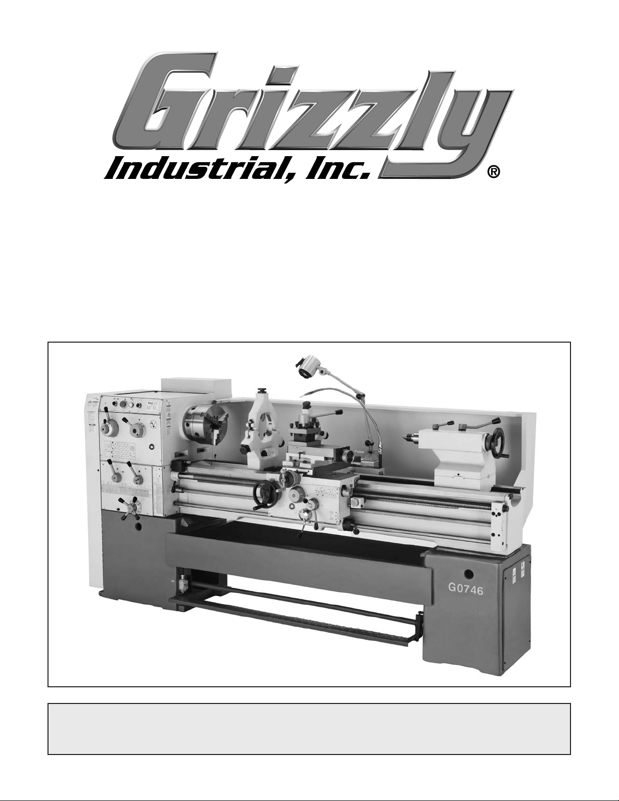
Carriage
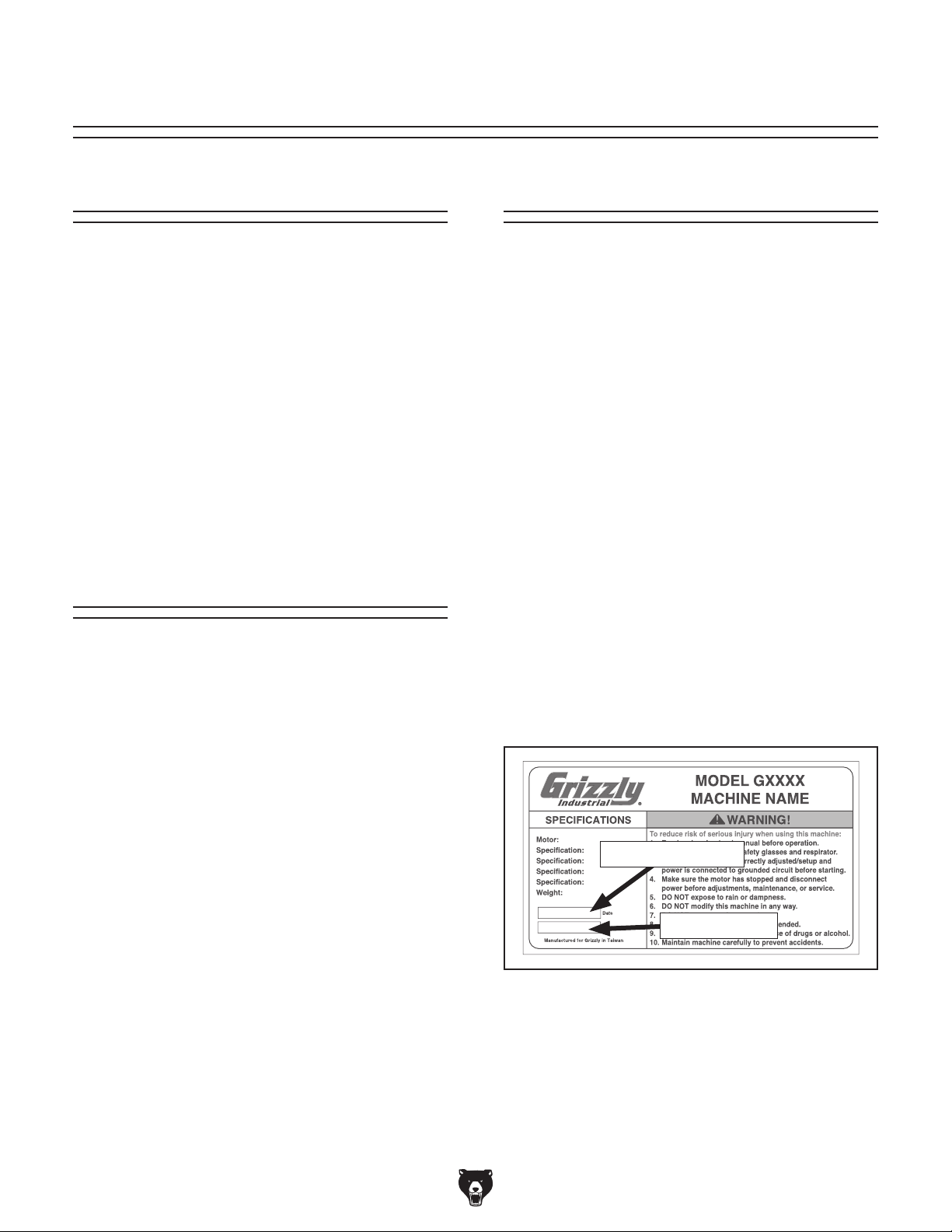
Tailstock
H
J
R
N
Q
H. 4-Way Tool Post: Holds up to four different
types of tooling, making it quick and easy to
switch tool type for different types of turning
operations.
I. Compound Rest Handwheel: Moves tool
toward and away from workpiece at preset
angle.
P
Figure 4. Carriage controls.
O
I
K
L
M
S
T
Figure 5. Additional tailstock controls.
X
U
V
W
Y
J. Carriage Lock: Secures carriage in place for
greater rigidity when it should not move.
K. Feed Selection Lever: Selects power feed
for carriage or cross slide.
L. Thread Dial: Indicates when to engage the
half nut during inch threading operations.
M. Spindle Lever: Starts, stops, and reverses
direction of spindle rotation.
N. Feed Lever: Enables carriage for power feed
or threading operations.
O. One-Shot Oiler: Pumps oil from apron res-
ervoir to lubricate carriage ways.
P. Half Nut Lever: Engages/disengages half
nut for threading operations.
Q. Carriage Handwheel: Moves carriage along
the bed.
R. Cross Slide Handwheel: Moves cross slide
toward and away from workpiece.
Figure 6. Tailstock controls.
S. Quill: Holds centers and tooling.
T. Quill Lock Lever: Secures quill in position.
U. Tailstock Lock Lever: Secures tailstock in
position along the bedway.
V. Graduated Scale: Indicates quill movement
in increments of 0.001" with one full revolution equaling 0.200" of quill travel.
W. Quill Handwheel: Moves quill toward or
away from spindle.
X. Tailstock Offset Screws: Adjusts tailstock
offset left or right from spindle centerline (1 of
2).
Y. Offset Scale: Indicates relative distance of
tailstock offset from spindle centerline.
-6-
Model G0746/G0749 (Mfg. Since 3/13)
Page 9
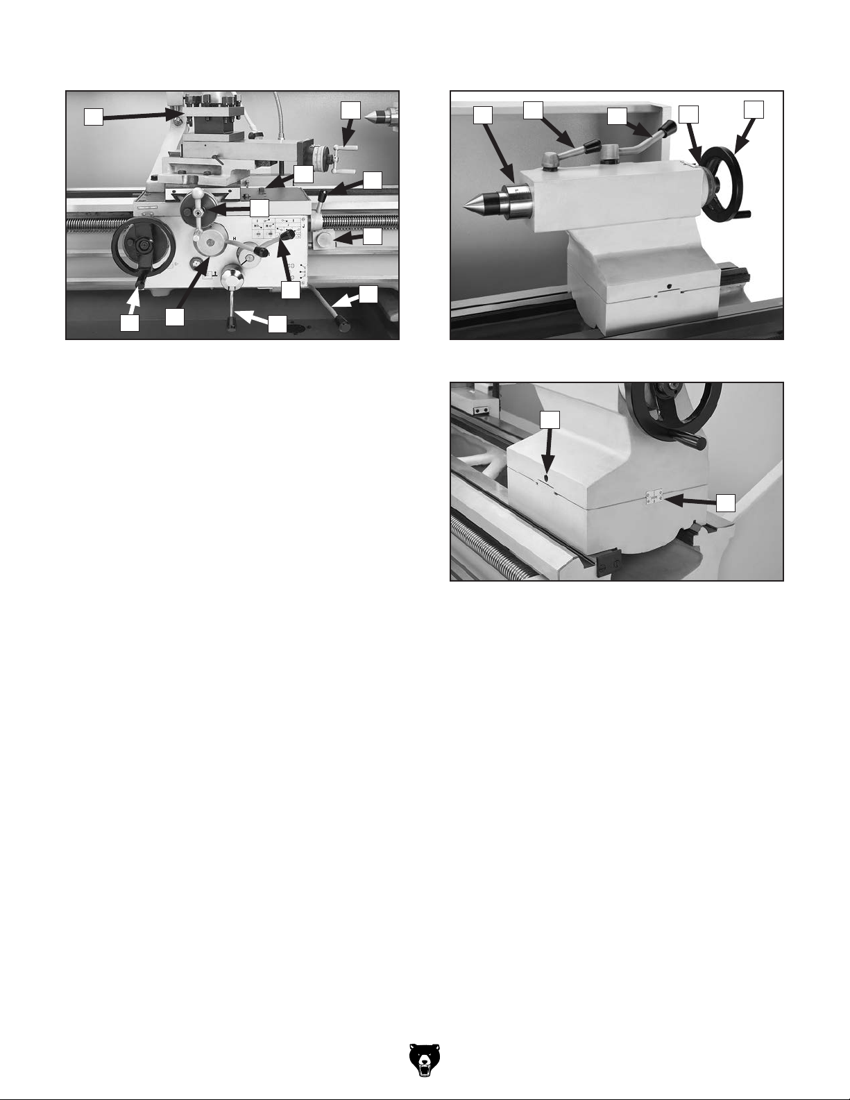
Control Panel Safety Foot Brake
This lathe is equipped with a foot brake (see
Figure 9) to quickly stop the spindle instead of
allowing the spindle to coast to a stop on its own.
Z
AC
AB
AA
Pushing the foot brake while the spindle is ON
cuts power to the motor and stops the spindle.
After the foot brake is used, the spindle lever
must be returned to the OFF (middle) position
to reset the spindle switches before re-starting
spindle rotation.
Figure 7. Control panel.
Z. Coolant Pump Switch: Controls coolant
pump motor.
AA. EMERGENCY STOP Button: Stops all
machine functions. Twist clockwise to reset.
AB. Power Lamp: Illuminates when main power
switch is turned ON and EMERGENCY STOP
button is reset.
AC. Jog/Inching Button: Powers forward spindle
rotation as long as it is pressed.
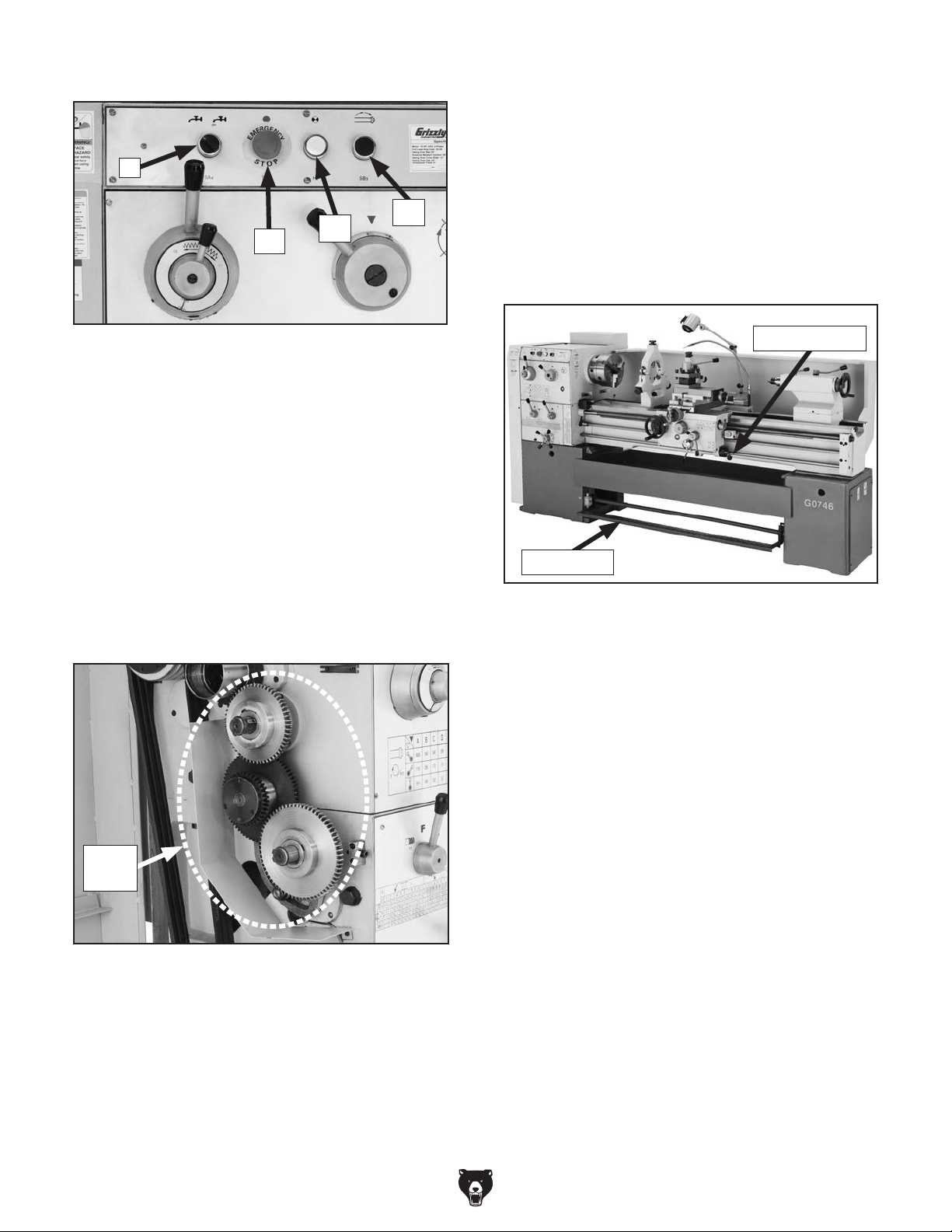
End Gears
Spindle Lever
Foot Brake
Figure 9. Foot brake and spindle lever.
End
Gears
Figure 8. End gear components.
Configuring the end gears (shown in Figure)
8 controls the speed of the leadscrew for threading or the feed rod for power feed operations.
Model G0746/G0749 (Mfg. Since 3/13)
-7-
Page 10

MACHINE DATA
SHEET
Customer Service #: (570) 546-9663 · To Order Call: (800) 523-4777 · Fax #: (800) 438-5901
MODEL G0746 20" X 60" LATHE
Product Dimensions:
Weight............................................................................................................................................................ 4145 lbs.
Width (side-to-side) x Depth (front-to-back) x Height............................................................. 108-1/4 x 42-1/2 x 59 in.
Footprint (Length x Width)............................................................................................................. 102-3/4 x 20-7/8 in.
Shipping Dimensions:
Type.......................................................................................................................................................... Wood Crate
Content........................................................................................................................................................... Machine
Weight............................................................................................................................................................ 5445 lbs.
Length x Width x Height..................................................................................................................... 115 x 45 x 69 in.
Must Ship Upright................................................................................................................................................... Yes
Electrical:
Power Requirement................................................................................................................... 220V, 3-Phase, 60 Hz
Prewired Voltage.................................................................................................................................................. 220V
Full-Load Current Rating................................................................................................................................... 30.35A
Minimum Circuit Size.............................................................................................................................................. 40A
Connection Type....................................................................................................................... Permanent (Hardwire)
Switch Type............................................................................................ Control Panel w/Magnetic Switch Protection
Recommended Phase Converter....................................................................................................................... H3741
Motors:
Main
Coolant Pump
Type........................................................................................................................................... TEFC Induction
Horsepower.............................................................................................................................................. 10 HP
Phase.................................................................................................................................................... 3-Phase
Amps............................................................................................................................................................ 30A
Speed................................................................................................................................................ 1725 RPM
Power Transfer ..................................................................................................................... Triple V-Belt Drive
Bearings..................................................................................................... Shielded & Permanently Lubricated
Type........................................................................................................................................... TEFC Induction
Horsepower............................................................................................................................................. 1/8 HP
Phase.................................................................................................................................................... 3-Phase
Amps......................................................................................................................................................... 0.35A
Speed................................................................................................................................................ 3450 RPM
Power Transfer ............................................................................................................................... Direct Drive
Bearings..................................................................................................... Shielded & Permanently Lubricated
-8-
Model G0746/G0749 (Mfg. Since 3/13)
Page 11

Main Specifications:
Operation Info
Swing Over Bed......................................................................................................................................... 20 in.
Distance Between Centers........................................................................................................................ 60 in.
Max Weight Between Centers............................................................................................................. 1300 lbs.
Swing Over Cross Slide............................................................................................................................. 13 in.
Swing Over Saddle.................................................................................................................................... 13 in.
Swing Over Gap........................................................................................................................................ 25 in.
Maximum Tool Bit Size................................................................................................................................ 1 in.
Compound Travel........................................................................................................................................ 5 in.
Carriage Travel.......................................................................................................................................... 60 in.
Cross Slide Travel..................................................................................................................................... 13 in.
Headstock Info
Spindle Bore........................................................................................................................................... 3.15 in.
Spindle Taper............................................................................................................................................ MT#7
Number of Spindle Speeds............................................................................................................................. 15
Spindle Speeds......................................................................................................................... 24 – 1600 RPM
Spindle Type................................................................................................................................ D1-8 Camlock
Spindle Bearings........................................................................................................................ Tapered Roller
Spindle Length..................................................................................................................................... 28-1/8 in.
Spindle Length with 3-Jaw Chuck.............................................................................................................. 33 in.
Spindle Length with 4-Jaw Chuck....................................................................................................... 32-7/8 in.
Spindle Length with Faceplate............................................................................................................ 29-7/8 in.
Tailstock Info
Tailstock Quill Travel............................................................................................................................. 4-3/4 in.
Tailstock Taper.......................................................................................................................................... MT#5
Tailstock Barrel Diameter......................................................................................................................... 2.6 in.
Threading Info
Number of Longitudinal Feeds....................................................................................................................... 66
Range of Longitudinal Feeds........................................................................................ 0.0027 – 0.1500 in./rev.
Number of Cross Feeds................................................................................................................................. 66
Range of Cross Feeds................................................................................................... 0.0013 – 0.0750 in./rev
Number of Inch Threads................................................................................................................................. 66
Range of Inch Threads...................................................................................................................... 1 – 56 TPI
Number of Metric Threads.............................................................................................................................. 66
Range of Metric Threads................................................................................................................ 0.5 – 28 mm
Number of Modular Pitches............................................................................................................................ 33
Range of Modular Pitches.............................................................................................................. 0.5 – 3.5 MP
Number of Diametral Pitches.......................................................................................................................... 33
Range of Diametral Pitches................................................................................................................ 8 – 56 DP
Dimensions
Bed Width.................................................................................................................................................. 13 in.
Leadscrew Diameter.............................................................................................................................. 1-3/8 in.
Leadscrew TPI........................................................................................................................................... 4 TPI
Leadscrew Length............................................................................................................................... 79-1/2 in.
Steady Rest Capacity............................................................................................................................ 6-1/4 in.
Follow Rest Capacity......................................................................................................................... 3-15/16 in.
Faceplate Size........................................................................................................................................... 17 in.
Feed Rod Diameter.............................................................................................................................. 13/16 in.
Floor to Center Height......................................................................................................................... 45-1/4 in.
Height With Leveling Jacks........................................................................................................................ 63 in.
Model G0746/G0749 (Mfg. Since 3/13)
-9-
Page 12

Construction
Base..................................................................................................................................................... Cast Iron
Headstock............................................................................................................................................ Cast Iron
Headstock Gears........................................................................................................................................ Steel
Bed.................................................................................................. Hardened and Precision-Ground Cast Iron
Body..................................................................................................................................................... Cast Iron
Stand.................................................................................................................................................... Cast Iron
Paint......................................................................................................................................................... Epoxy
Fluid Capacities
Headstock Capacity................................................................................................................................... 18 qt.
Headstock Fluid Type................................................................ ISO 32 (eg. Grizzly T23963, Mobil DTE Light)
Gearbox Capacity..................................................................................................................................... 9.5 qt.
Gearbox Fluid Type...................................................................... ISO 68 (eg. Grizzly T23962, Mobil Vactra 2)
Apron Capacity......................................................................................................................................... 6.5 qt.
Apron Fluid Type.......................................................................... ISO 68 (eg. Grizzly T23962, Mobil Vactra 2)
Coolant Capacity.................................................................................................................................. 21.25 qt.
Other Specifications:
Country Of Origin ............................................................................................................................................... China
Warranty ........................................................................................................................................................... 1 Year
Approximate Assembly & Setup Time ............................................................................................................. 2 Hours
Serial Number Location ..................................................................................................... ID Label on Front of Lathe
Sound Rating ..................................................................................................................................................... 85 dB
ISO 9001 Factory .................................................................................................................................................. Yes
CSA Certified .......................................................................................................................................................... No
Features:
Full-length splash guard
Apron-mounted ON/OFF/reverse spindle lever
Chip tray slides out for easy cleaning
Cast iron stand
Foot brake
Coolant system
Halogen light
Headstock gears run in an oil bath
Jog button and emergency stop button
Quick-change tool post
Micrometer stop
Universal gearbox allows cutting of inch, metric threads, and modular and diametral pitches
Accessories Included:
Steady rest
Follow rest
2 MT#5 dead centers
Center sleeve
10" 3-Jaw chuck with 2 sets of jaws
12" 4-Jaw chuck with reversible jaws
Two change gears
8 leveling pads
Tool box
Service tools
Manual
-10 -
Model G0746/G0749 (Mfg. Since 3/13)
Page 13

MACHINE DATA
SHEET
Customer Service #: (570) 546-9663 · To Order Call: (800) 523-4777 · Fax #: (800) 438-5901
MODEL G0749 16 X 40 HEAVY DUTY LATHE
Product Dimensions:
Weight............................................................................................................................................................ 3616 lbs.
Width (side-to-side) x Depth (front-to-back) x Height........................................................ 88-5/8 x 42-1/2 x 55-1/8 in.
Footprint (Length x Width)............................................................................................................................ 84 x 21 in.
Shipping Dimensions:
Type.......................................................................................................................................................... Wood Crate
Content........................................................................................................................................................... Machine
Weight............................................................................................................................................................ 5049 lbs.
Length x Width x Height....................................................................................................................... 96 x 45 x 69 in.
Must Ship Upright................................................................................................................................................... Yes
Electrical:
Power Requirement................................................................................................................... 220V, 3-Phase, 60 Hz
Prewired Voltage.................................................................................................................................................. 220V
Full-Load Current Rating..................................................................................................................................... 30.3A
Minimum Circuit Size.............................................................................................................................................. 40A
Connection Type....................................................................................................................... Permanent (Hardwire)
Switch Type............................................................................................ Control Panel w/Magnetic Switch Protection
Recommended Phase Converter....................................................................................................................... H3741
Motors:
Main
Coolant Pump
Type........................................................................................................................................... TEFC Induction
Horsepower.............................................................................................................................................. 10 HP
Phase.................................................................................................................................................... 3-Phase
Amps............................................................................................................................................................ 30A
Speed................................................................................................................................................ 1725 RPM
Power Transfer ............................................................................................................................... V-Belt Drive
Bearings..................................................................................................... Shielded & Permanently Lubricated
Type........................................................................................................................................... TEFC Induction
Horsepower............................................................................................................................................. 1/8 HP
Phase.................................................................................................................................................... 3-Phase
Amps........................................................................................................................................................... 0.3A
Speed................................................................................................................................................ 1725 RPM
Power Transfer ............................................................................................................................... Direct Drive
Bearings..................................................................................................... Shielded & Permanently Lubricated
Model G0746/G0749 (Mfg. Since 3/13)
-11-
Page 14

Main Specifications:
Operation Info
Headstock Info
Tailstock Info
Swing Over Bed......................................................................................................................................... 16 in.
Distance Between Centers........................................................................................................................ 40 in.
Max Weight Between Centers............................................................................................................. 1300 lbs.
Swing Over Cross Slide............................................................................................................................... 9 in.
Swing Over Saddle.............................................................................................................................. 13-3/4 in.
Swing Over Gap........................................................................................................................................ 21 in.
Maximum Tool Bit Size................................................................................................................................ 1 in.
Compound Travel........................................................................................................................................ 5 in.
Carriage Travel.......................................................................................................................................... 40 in.
Cross Slide Travel..................................................................................................................................... 13 in.
Spindle Bore........................................................................................................................................... 3.15 in.
Spindle Taper............................................................................................................................................ MT#7
Number of Spindle Speeds............................................................................................................................. 15
Spindle Speeds......................................................................................................................... 24 – 1600 RPM
Spindle Type................................................................................................................................ D1-8 Camlock
Spindle Bearings........................................................................................................................ Tapered Roller
Spindle Length..................................................................................................................................... 28-1/8 in.
Spindle Length with 3-Jaw Chuck.............................................................................................................. 33 in.
Spindle Length with 4-Jaw Chuck....................................................................................................... 32-7/8 in.
Spindle Length with Faceplate............................................................................................................ 29-7/8 in.
Tailstock Quill Travel............................................................................................................................. 4-3/4 in.
Tailstock Taper.......................................................................................................................................... MT#5
Tailstock Barrel Diameter......................................................................................................................... 2.6 in.
Threading Info
Number of Longitudinal Feeds....................................................................................................................... 66
Range of Longitudinal Feeds........................................................................................ 0.0027 – 0.1500 in./rev.
Number of Cross Feeds................................................................................................................................. 66
Range of Cross Feeds................................................................................................... 0.0013 – 0.0750 in./rev
Number of Inch Threads................................................................................................................................. 66
Range of Inch Threads...................................................................................................................... 1 – 56 TPI
Number of Metric Threads.............................................................................................................................. 66
Range of Metric Threads................................................................................................................ 0.5 – 28 mm
Number of Modular Pitches............................................................................................................................ 33
Range of Modular Pitches.............................................................................................................. 0.5 – 3.5 MP
Number of Diametral Pitches.......................................................................................................................... 33
Range of Diametral Pitches................................................................................................................ 8 – 56 DP
Dimensions
Bed Width.................................................................................................................................................. 13 in.
Leadscrew Diameter.............................................................................................................................. 1-3/8 in.
Leadscrew TPI........................................................................................................................................... 4 TPI
Leadscrew Length............................................................................................................................... 59-7/8 in.
Steady Rest Capacity............................................................................................................................ 6-1/4 in.
Follow Rest Capacity............................................................................................................................. 3-7/8 in.
Faceplate Size........................................................................................................................................... 15 in.
Feed Rod Diameter.................................................................................................................................. 7/8 in.
Floor to Center Height....................................................................................................................... 41-5/16 in.
-12-
Model G0746/G0749 (Mfg. Since 3/13)
Page 15

Construction
Fluid Capacities
Other Specifications:
Country Of Origin ............................................................................................................................................... China
Warranty ........................................................................................................................................................... 1 Year
Approximate Assembly & Setup Time ............................................................................................................. 2 Hours
Serial Number Location ........................................................................................................... ID Label on Headstock
ISO 9001 Factory .................................................................................................................................................. Yes
CSA Certified .......................................................................................................................................................... No
Features:
Full length splash guard
Apron-mounted ON/OFF/reverse spindle lever
Chip tray slides out for easy cleaning
Cast iron stand
Foot brake
Coolant system
Halogen light
Headstock gears run in an oil bath
Jog button and emergency stop
Quick-change tool post
Micrometer stop
Universal gearbox allows cutting of inch, metric threads, and modular and diametral pitches
Base..................................................................................................................................................... Cast Iron
Headstock............................................................................................................................................ Cast Iron
Headstock Gears........................................................................................................................................ Steel
Bed.................................................................................................. Hardened and Precision-Ground Cast Iron
Body..................................................................................................................................................... Cast Iron
Stand.................................................................................................................................................... Cast Iron
Paint......................................................................................................................................................... Epoxy
Headstock Capacity.............................................................................................................................. 12.75 qt.
Headstock Fluid Type................................................................ ISO 32 (eg. Grizzly T23963, Mobil DTE Light)
Gearbox Capacity..................................................................................................................................... 9.5 qt.
Gearbox Fluid Type...................................................................... ISO 68 (eg. Grizzly T23962, Mobil Vactra 2)
Apron Capacity......................................................................................................................................... 6.5 qt.
Apron Fluid Type.......................................................................... ISO 68 (eg. Grizzly T23962, Mobil Vactra 2)
Coolant Capacity.................................................................................................................................. 21.25 qt.
Accessories Included:
Steady rest
Follow rest
15" faceplate
MT#5 dead center
MT#7 to MT#5 sleeve
10" 3-Jaw chuck with 2 sets of jaws
12-1/2" 4-Jaw chuck with reversible jaws
Two change gears
8 leveling pads
4-Way tool post
Tool box
Service tools
Oil gun
Manual
Model G0746/G0749 (Mfg. Since 3/13)
-13-
Page 16

SECTION 1: SAFETY
For Your Own Safety, Read Instruction
Manual Before Operating This Machine
The purpose of safety symbols is to attract your attention to possible hazardous conditions.
This manual uses a series of symbols and signal words intended to convey the level of importance of the safety messages. The progression of symbols is described below. Remember that
safety messages by themselves do not eliminate danger and are not a substitute for proper
accident prevention measures. Always use common sense and good judgment.
Indicates an imminently hazardous situation which, if not avoided,
WILL result in death or serious injury.
Indicates a potentially hazardous situation which, if not avoided,
COULD result in death or serious injury.
Indicates a potentially hazardous situation which, if not avoided,
MAY result in minor or moderate injury. It may also be used to alert
against unsafe practices.
This symbol is used to alert the user to useful information about
NOTICE
proper operation of the machine.
Safety Instructions for Machinery
OWNER’S MANUAL. Read and understand this
owner’s manual BEFORE using machine.
TRAINED OPERATORS ONLY. Untrained operators have a higher risk of being hurt or killed.
Only allow trained/supervised people to use this
machine. When machine is not being used, disconnect power, remove switch keys, or lock-out
machine to prevent unauthorized use—especially
around children. Make workshop kid proof!
DANGEROUS ENVIRONMENTS. Do not use
machinery in areas that are wet, cluttered, or have
poor lighting. Operating machinery in these areas
greatly increases the risk of accidents and injury.
MENTAL ALERTNESS REQUIRED. Full mental
alertness is required for safe operation of machinery. Never operate under the influence of drugs or
alcohol, when tired, or when distracted.
ELECTRICAL EQUIPMENT INJURY RISKS. You
can be shocked, burned, or killed by touching live
electrical components or improperly grounded
machinery. To reduce this risk, only allow qualified
service personnel to do electrical installation or
repair work, and always disconnect power before
accessing or exposing electrical equipment.
DISCONNECT POWER FIRST.
nect machine from power supply BEFORE making
adjustments, changing tooling, or servicing machine.
This prevents an injury risk from unintended startup
or contact with live electrical components.
EYE PROTECTION. Always wear ANSI-approved
safety glasses or a face shield when operating or
observing machinery to reduce the risk of eye
injury or blindness from flying particles. Everyday
eyeglasses are NOT approved safety glasses.
Always discon-
-14-
Model G0746/G0749 (Mfg. Since 3/13)
Page 17

WEARING PROPER APPAREL. Do not wear
clothing, apparel or jewelry that can become
entangled in moving parts. Always tie back or
cover long hair. Wear non-slip footwear to avoid
accidental slips, which could cause loss of workpiece control.
HAZARDOUS DUST. Dust created while using
machinery may cause cancer, birth defects, or
long-term respiratory damage. Be aware of dust
hazards associated with each workpiece material,
and always wear a NIOSH-approved respirator to
reduce your risk.
HEARING PROTECTION. Always wear hearing protection when operating or observing loud
machinery. Extended exposure to this noise
without hearing protection can cause permanent
hearing loss.
REMOVE ADJUSTING TOOLS. Tools left on
machinery can become dangerous projectiles
upon startup. Never leave chuck keys, wrenches,
or any other tools on machine. Always verify
removal before starting!
USE CORRECT TOOL FOR THE JOB. Only use
this tool for its intended purpose—do not force
it or an attachment to do a job for which it was
not designed. Never make unapproved modifications—modifying tool or using it differently than
intended may result in malfunction or mechanical
failure that can lead to personal injury or death!
AWKWARD POSITIONS. Keep proper footing
and balance at all times when operating machine.
Do not overreach! Avoid awkward hand positions
that make workpiece control difficult or increase
the risk of accidental injury.
CHILDREN & BYSTANDERS. Keep children and
bystanders at a safe distance from the work area.
Stop using machine if they become a distraction.
FORCING MACHINERY. Do not force machine.
It will do the job safer and better at the rate for
which it was designed.
NEVER STAND ON MACHINE. Serious injury
may occur if machine is tipped or if the cutting
tool is unintentionally contacted.
STABLE MACHINE. Unexpected movement during operation greatly increases risk of injury or
loss of control. Before starting, verify machine is
stable and mobile base (if used) is locked.
USE RECOMMENDED ACCESSORIES. Consult
this owner’s manual or the manufacturer for recommended accessories. Using improper accessories will increase the risk of serious injury.
UNATTENDED OPERATION. To reduce the
risk of accidental injury, turn machine OFF and
ensure all moving parts completely stop before
walking away. Never leave machine running
while unattended.
MAINTAIN WITH CARE. Follow all maintenance
instructions and lubrication schedules to keep
machine in good working condition. A machine
that is improperly maintained could malfunction,
leading to serious personal injury or death.
CHECK DAMAGED PARTS. Regularly inspect
machine for any condition that may affect safe
operation. Immediately repair or replace damaged
or mis-adjusted parts before operating machine.
MAINTAIN POWER CORDS. When disconnecting cord-connected machines from power, grab
and pull the plug—NOT the cord. Pulling the cord
may damage the wires inside. Do not handle
cord/plug with wet hands. Avoid cord damage by
keeping it away from heated surfaces, high traffic
areas, harsh chemicals, and wet/damp locations.
GUARDS & COVERS. Guards and covers reduce
accidental contact with moving parts or flying
debris. Make sure they are properly installed,
undamaged, and working correctly.
Model G0746/G0749 (Mfg. Since 3/13)
EXPERIENCING DIFFICULTIES. If at any time
you experience difficulties performing the intended operation, stop using the machine! Contact our
Technical Support at (570) 546-9663.
-15-
Page 18

Additional Safety for Metal Lathes
Never attempt to slow or stop the lathe spindle with
SPEED RATES. Operating the lathe at the wrong
speed can cause nearby parts to break or the
workpiece to come loose, which will result in dangerous projectiles that could cause severe impact
injuries. Large or non-concentric workpieces must
be turned at slow speeds. Always use the appropriate feed and speed rates.
CHUCK KEY SAFETY. A chuck key left in the
chuck can become a deadly projectile when the
spindle is started. Always remove the chuck key
after using it. Develop a habit of not taking your
hand off of a chuck key unless it is away from the
machine.
SAFE CLEARANCES. Workpieces that crash
into other components on the lathe may throw
dangerous projectiles in all directions, leading to
impact injury and damaged equipment. Before
starting the spindle, make sure the workpiece has
adequate clearance by hand-rotating it through its
entire range of motion. Also, check the tool and
tool post clearance, chuck clearance, and saddle
clearance.
LONG STOCK SAFETY. Long stock can whip
violently if not properly supported, causing serious
impact injury and damage to the lathe. Reduce this
risk by supporting any stock that extends from the
chuck/headstock more than three times its own
diameter. Always turn long stock at slow speeds.
SECURING WORKPIECE. An improperly secured
workpiece can fly off the lathe spindle with deadly
force, which can result in a severe impact injury.
Make sure the workpiece is properly secured in the
chuck or faceplate before starting the lathe.
CHUCKS. Chucks are very heavy and difficult to
grasp, which can lead to crushed fingers or hands
if mishandled. Get assistance when handling
chucks to reduce this risk. Protect your hands and
the precision-ground ways by using a chuck cradle
or piece of plywood over the ways of the lathe
when servicing chucks. Use lifting devices when
necessary.
CLEARING CHIPS. Metal chips can easily cut
bare skin—even through a piece of cloth. Avoid
clearing chips by hand or with a rag. Use a brush
or vacuum to clear metal chips.
STOPPING SPINDLE BY HAND. Stopping the
spindle by putting your hand on the workpiece
or chuck creates an extreme risk of entanglement, impact, crushing, friction, or cutting hazards.
your hand. Allow the spindle to come to a stop on
its own or use the brake.
CRASHES. Aggressively driving the cutting tool or
other lathe components into the chuck may cause
an explosion of metal fragments, which can result
in severe impact injuries and major damage to
the lathe. Reduce this risk by releasing automatic
feeds after use, not leaving lathe unattended, and
checking clearances before starting the lathe.
Make sure no part of the tool, tool holder, compound rest, cross slide, or carriage will contact the
chuck during operation.
COOLANT SAFETY. Coolant is a very poisonous biohazard that can cause personal injury from
skin contact alone. Incorrectly positioned coolant
nozzles can splash on the operator or the floor,
resulting in an exposure or slipping hazard. To
decrease your risk, change coolant regularly and
position the nozzle where it will not splash or end
up on the floor.
TOOL SELECTION. Cutting with an incorrect or
dull tool increases the risk of accidental injury due
to the extra force required for the operation, which
increases the risk of breaking or dislodging components that can cause small shards of metal to
become dangerous projectiles. Always select the
right cutter for the job and make sure it is sharp. A
correct, sharp tool decreases strain and provides
a better finish.
-16 -
Model G0746/G0749 (Mfg. Since 3/13)
Page 19

Additional Chuck Safety
ENTANGLEMENT. Entanglement with a rotat-
ing chuck can lead to death, amputation, broken
bones, or other serious injury. Never attempt to
slow or stop the lathe chuck by hand, and always
roll up long sleeves, tie back long hair, and remove
any jewelry or loose apparel BEFORE operating.
CHUCK SPEED RATING. Excessive spindle
speeds greatly increase the risk of the workpiece
or chuck being thrown from the machine with
deadly force. Never use spindle speeds faster than
the chuck RPM rating or the safe limits of your
workpiece.
USING CORRECT EQUIPMENT. Many workpieces can only be safely turned in a lathe if additional
support equipment, such as a tailstock or steady/
follow rest, is used. If the operation is too hazardous to be completed with the lathe or existing
equipment, the operator must have enough experience to know when to use a different machine or
find a safer way.
TRAINED OPERATORS ONLY. Using a chuck
incorrectly can result in workpieces coming loose
at high speeds and striking the operator or bystanders with deadly force. To reduce the risk of this hazard, read and understand this document and seek
additional training from an experienced chuck user
before using a chuck.
CHUCK CAPACITY. Avoid exceeding the capacity
of the chuck by clamping an oversized workpiece.
If the workpiece is too large to safely clamp with
the chuck, use a faceplate or a larger chuck if possible. Otherwise, the workpiece could be thrown
from the lathe during operation, resulting in serious
impact injury or death.
CLAMPING FORCE. Inadequate clamping force
can lead to the workpiece being thrown from the
chuck and striking the operator or bystanders.
Maximum clamping force is achieved when the
chuck is properly maintained and lubricated, all
jaws are fully engaged with the workpiece, and
the maximum chuck clamping diameter is not
exceeded.
PROPER MAINTENANCE. All chucks must be
properly maintained and lubricated to achieve
maximum clamping force and withstand the rigors
of centrifugal force. To reduce the risk of a thrown
workpiece, follow all maintenance intervals and
instructions in this document.
DISCONNECT POWER. Serious entanglement or
impact injuries could occur if the lathe is started
while you are adjusting, servicing, or installing the
chuck. Always disconnect the lathe from power
before performing these procedures.
Model G0746/G0749 (Mfg. Since 3/13)
-17-
Page 20

SECTION 2: POWER SUPPLY
Before installing the machine, consider the availability and proximity of the required power supply
circuit. If an existing circuit does not meet the
requirements for this machine, a new circuit must
be installed. To minimize the risk of electrocution,
fire, or equipment damage, installation work and
electrical wiring must be done by an electrican or
qualified service personnel in accordance with all
applicable codes and standards.
Electrocution, fire, or
equipment damage may
occur if machine is not
correctly grounded and
connected to the power
The full-load current rating is the amperage a
machine draws at 100% of the rated output power.
On machines with multiple motors, this is the
amperage drawn by the largest motor or sum of all
motors and electrical devices that might operate
at one time during normal operations.
The full-load current is not the maximum amount
of amps that the machine will draw. If the machine
is overloaded, it will draw additional amps beyond
the full-load rating.
If the machine is overloaded for a sufficient length
of time, damage, overheating, or fire may result—
especially if connected to an undersized circuit.
To reduce the risk of these hazards, avoid overloading the machine during operation and make
sure it is connected to a power supply circuit that
meets the requirements in the following section.
This machine is prewired to operate on a 220V
power supply circuit that has a verified ground and
meets the following requirements:
For your own safety and protection of
Note: The circuit requirements listed in this manual apply to a dedicated circuit—where only one
machine will be running at a time. If this machine
will be connected to a shared circuit where multiple machines will be running at the same time,
consult a qualified electrician to ensure that the
circuit is properly sized for safe operation.
A power supply circuit includes all electrical
equipment between the breaker box or fuse panel
in the building and the machine. The power supply circuit used for this machine must be sized to
safely handle the full-load current drawn from the
machine for an extended period of time. (If this
machine is connected to a circuit protected by
fuses, use a time delay fuse marked D.)
Availability
supply.
Full-Load Current Rating
Circuit Requirements for 220V
Nominal Voltage ........................................220V
Cycle ..........................................................60 Hz
Phase .................................................... 3-Phase
Power Supply Circuit ......................... 40 Amps
Connection Type ............................... Hardwire
Full-Load Current Rating .............. 30.35 Amps
-18-
property, consult an electrician if you are
unsure about wiring practices or electrical
codes in your area.
Model G0746/G0749 (Mfg. Since 3/13)
Page 21
Connection Type
A permanently connected (hardwired) power supply is typically installed with wires running through
mounted and secured conduit. A disconnecting
means, such as a locking switch (see following
figure), must be provided to allow the machine
to be disconnected (isolated) from the power
supply when required. This installation must be
performed by an electrician in accordance with all
applicable electrical codes and ordinances.
In the event of a malfunction or breakdown,
grounding provides a path of least resistance
for electrical current to reduce the risk of electric
shock. A permanently connected machine must
be connected to a grounded metal permanent wir
ing system; or to a system having an equipmentgrounding conductor. All grounds must be verified
and rated for the electrical requirements of the
machine. Improper grounding can increase the
risk of electric shock!
Since this machine must be permanently connected to the power supply, an extension cord
cannot be used.
Locking
Disconnect Switch
Power
Source
Ground
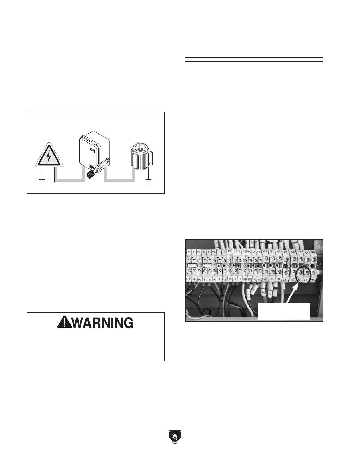
Correcting Phase
Polarity
This sub-section is only provided for troubleshooting. If you discover that the lathe will not operate,
or that the spindle runs backwards, the lathe may
be wired out of phase.
Correcting phase polarity requires reversing the
positions where two incoming power source wires
are connected. Due to the high voltage and risk of
serious shock involved, we strongly recommend
Machine
ConduitConduit
Ground
this procedure only be done by an electrician or
qualified service personnel.
To correct the phase polarity of the incoming
power supply:
1. DISCONNECT MACHINE FROM POWER!
Figure 10. Typical setup of a permanently
connected machine.
Grounding Instructions
Serious injury could occur if you connect
the machine to power before completing the
setup process. DO NOT connect to power
until instructed later in this manual.
2. Open electrical box located at back of
machine.
3. Swap the incoming L1 and L2 wire positions
on the terminals shown in Figure 11.
-
Swap Any Two
Wires Here
Figure 11. Swapping power connections to
correct out-of-phase wiring.
3. Close and latch electrical box.
4. Reconnect machine to power supply.
Extension Cords
Model G0746/G0749 (Mfg. Since 3/13)
-19 -
Page 22

SECTION 3: SETUP
Your machine was carefully packaged for safe
transportation. Remove the packaging materials
from around your machine and inspect it. If you
discover any damage, please call us immediately
at (570) 546-9663
Save the containers and all packing materials for
possible inspection by the carrier or its agent.
Otherwise, filing a freight claim can be difficult.
When you are completely satisfied with the condition of your shipment, inventory the contents.
Keep children and pets away
from plastic bags or packing
materials shipped with this
Preparation
The list below outlines the basic process of preparing your machine for operation. Specific steps
are covered later in this section.
The typical preparation process is as follows:
SUFFOCATION HAZARD!
machine. Discard immediately.
1. Unpack the lathe and inventory the contents
of the box/crate.
2. Clean the lathe and its components.
3. Identify an acceptable location for the lathe
and move it to that location.
4. Level the lathe and bolt it to the floor, or place
it on leveling pads.
5. Assemble the loose components and make
any necessary adjustments or inspections to
ensure the lathe is ready for operation.
6. Check lathe for proper lubrication.
7. Connect the lathe to the power source.
8. Test run lathe to ensure it functions properly.
9. Perform the spindle break-in procedure to
prepare the lathe for operation.
Unpacking
for advice.
Needed for Setup
The following are needed to complete the setup
process, but are not included with your machine.
• For Lifting and Moving:
— A forklift or other power lifting device rated
for at least 6800 lbs.
— Two lifting straps rated for at least 6800 lbs.
each
—1" diameter x 49" long steel barstock
— Two people to guide machine
• For Power Connection:
— A power source that meets the minimum cir-
cuit requirements for this machine (review
Power Supply on Page 18 for details)
— An electrician or qualified service person-
nel to ensure a safe and code-compliant
connection to the power source
• For Assembly:
— Shop rags
— Cleaner/degreaser (see Page 22)
— Quality metal protectant lubricant
— Safety glasses for each person
— Floor mounting hardware as needed (see
Page 25)
— Precision level at least 1" long
-20-
Model G0746/G0749 (Mfg. Since 3/13)
Page 23
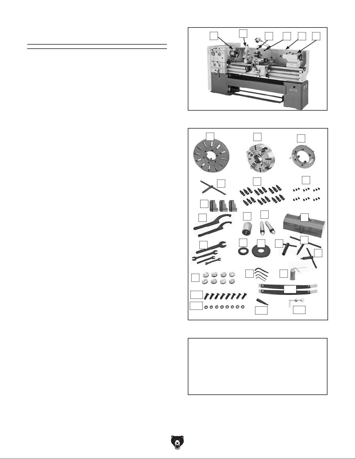
Inventory
The following is a list of items shipped with your
machine. Before beginning setup, lay these items
out and inventory them.
If any non-proprietary parts are missing (e.g. a
nut or a washer), we will gladly replace them; or
for the sake of expediency, replacements can be
obtained at your local hardware store.
Main Components (Figure 12) Qty.
A. Three-Jaw Chuck 10" (Installed) ................ 1
B. Steady Rest ................................................ 1
C. Follow Rest ................................................. 1
D. 4-Way Tool Post ......................................... 1
E. Backsplash ................................................. 1
F. Ta ils tock ...................................................... 1
Packaged Components (Figure 13)
G. Faceplate 17" ............................................. 1
H. Four-Jaw Chuck 12" ................................... 1
I. Drive Plate .................................................. 1
J. 4-Jaw Chuck Wrench ................................. 1
K. Camlock Studs (6 Installed) ..................... 18
L. Cap Screws M6-1 x 14 (6 Installed) ......... 18
M. Three-Jaw Chuck Outside Jaws ................ 3
N. Spanner Wrenches ..................................... 2
O. Tapered Spindle Sleeve MT-7-#5 ............... 1
P. Standard Dead Centers MT#5 ................... 2
Q. To o l Box ...................................................... 1
R. Spindle Wrench .......................................... 1
S. 3-Jaw Chuck Wrench ................................ 1
T. Tool Post T-Wrench .................................... 1
U. Spare Change Gear 72T ............................ 1
V. Spare Change Gear 36T ............................ 1
W. Wrenches 10/13, 17, 19/24, 36 mm ....... 1 ea
X. Cast Iron Leveling Pads ............................. 8
Y. Hex Wrenches 5, 6, 8, 10 mm ............... 1 ea
Z. Oil Gun ....................................................... 1
AA. Spare Brake Belts ...................................... 2
AB. Leveling Bolts M16-2 x 45 .......................... 8
AC. Hex Nuts M16-2 .......................................... 8
AD. Carriage Handwheel Handle ...................... 1
AE. Cross Slide Handwheel .............................. 1
A
Figure 12. Main components.
G
J
M
N
W
X
AB
AC
Figure 13. Packaged components.
B
O
V
Y
C D E F
H
K
P
TU
Z
AA
AD
I
L
Q
R
S
AE
NOTICE
If you cannot find an item on this list, carefully check around/inside the machine and
packaging materials. Often, these items get
lost in packaging materials while unpacking or they are pre-installed at the factory.
Model G0746/G0749 (Mfg. Since 3/13)
-21-
Page 24
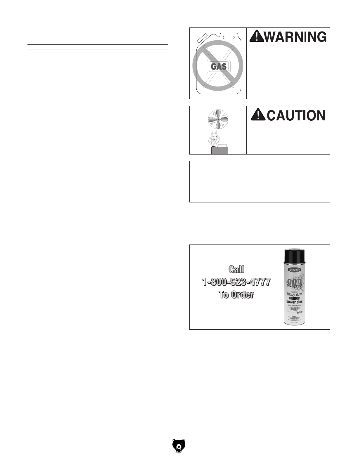
The unpainted surfaces of your machine are
coated with a heavy-duty rust preventative that
prevents corrosion during shipment and storage.
This rust preventative works extremely well, but it
will take a little time to clean.
Be patient and do a thorough job cleaning your
machine. The time you spend doing this now will
give you a better appreciation for the proper care
of your machine's unpainted surfaces.
There are many ways to remove this rust preventative, but the following steps work well in a wide
variety of situations. Always follow the manufacturer’s instructions with any cleaning product you
use and make sure you work in a well-ventilated
area to minimize exposure to toxic fumes.
Before cleaning, gather the following:
• Disposable rags
• Cleaner/degreaser (WD•40 works well)
• Safety glasses & disposable gloves
• Plastic paint scraper (optional)
Basic steps for removing rust preventative:
1.
2.
3.
4.
metal protectant to prevent rust.
Many cleaning solvents
work in a well-ventilated
Avoid chlorine-based solvents, such as
Cleanup
Gasoline and petroleum
products have low flash
points and can explode
or cause fire if used to
clean machinery. Avoid
using these products
to clean machinery.
are toxic if inhaled. Only
Put on safety glasses.
Coat the rust preventative with a liberal
amount of cleaner/degreaser, then let it soak
for 5–10 minutes.
Wipe off the surfaces. If your cleaner/degreas-
er is effective, the rust preventative will wipe
off easily. If you have a plastic paint scraper,
scrape off as much as you can first, then wipe
off the rest with the rag.
area.
NOTICE
acetone or brake parts cleaner, that may
damage painted surfaces.
T23692—Orange Power Degreaser
A great product for removing the waxy shipping
grease from your machine during clean up.
Figure 14. T23692 Orange Power Degreaser.
Repeat Steps 2–3 as necessary until clean,
then coat all unpainted surfaces with a quality
-22-
Model G0746/G0749 (Mfg. Since 3/13)
Page 25
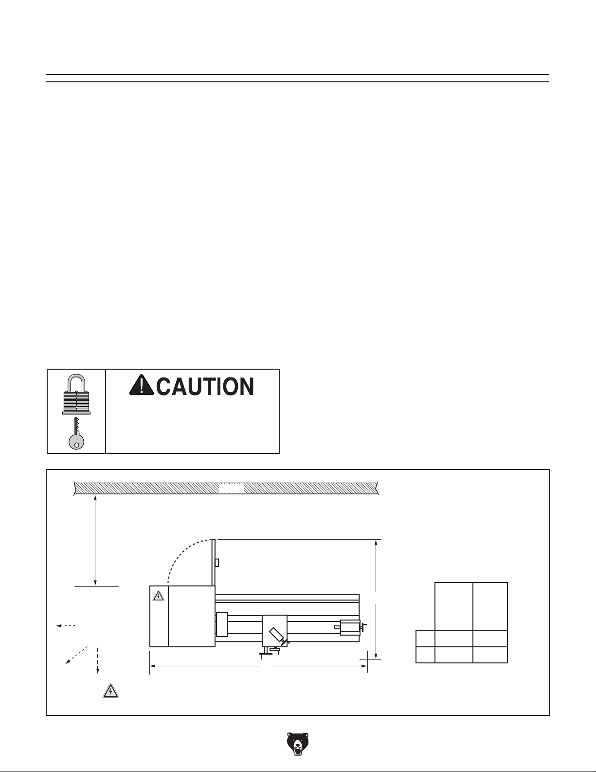
Site Considerations
Weight Load
Physical Environment
Place this machine near an existing power source.
Shadows, glare, or strobe effects that may distract
Refer to the Machine Data Sheet for the weight
of your machine. Make sure that the surface upon
which the machine is placed will bear the weight
of the machine, additional equipment that may be
installed on the machine, and the heaviest workpiece that will be used. Additionally, consider the
weight of the operator and any dynamic loading
that may occur when operating the machine.
Space Allocation
Consider the largest size of workpiece that will
be processed through this machine and provide
enough space around the machine for adequate
operator material handling or the installation of
auxiliary equipment. With permanent installations,
leave enough space around the machine to open
or remove doors/covers as required by the maintenance and service described in this manual.
See below for required space allocation.
Children or untrained people
may be seriously injured by
this machine. Only install in an
access restricted location.
The physical environment where the machine is
operated is important for safe operation and longevity of machine components. For best results,
operate this machine in a dry environment that is
free from excessive moisture, hazardous chemicals, airborne abrasives, or extreme conditions.
Extreme conditions for this type of machinery are
generally those where the ambient temperature
range exceeds 41°–104°F; the relative humidity
range exceeds 20–95% (non-condensing); or the
environment is subject to vibration, shocks, or
bumps.
Electrical Installation
Make sure all power cords are protected from
traffic, material handling, moisture, chemicals,
or other hazards. Make sure to leave access to
a means of disconnecting the power source or
engaging a lockout/tagout device, if required.
Lighting
Lighting around the machine must be adequate
enough that operations can be performed safely.
or impede the operator must be eliminated.
Electrical
Min. 30"
Keep
Workpiece
Loading Area
Unobstructed
= Electrical Connection
Model G0746/G0749 (Mfg. Since 3/13)
Cabinet
Lathe
Figure 15. Minimum working clearances.
Wall
B
A
B
A
Illustration Not To Scale
G0746
112 " 92
1
15
⁄2 " 151⁄2 "
G0749
1
⁄2 "
-23-
Page 26
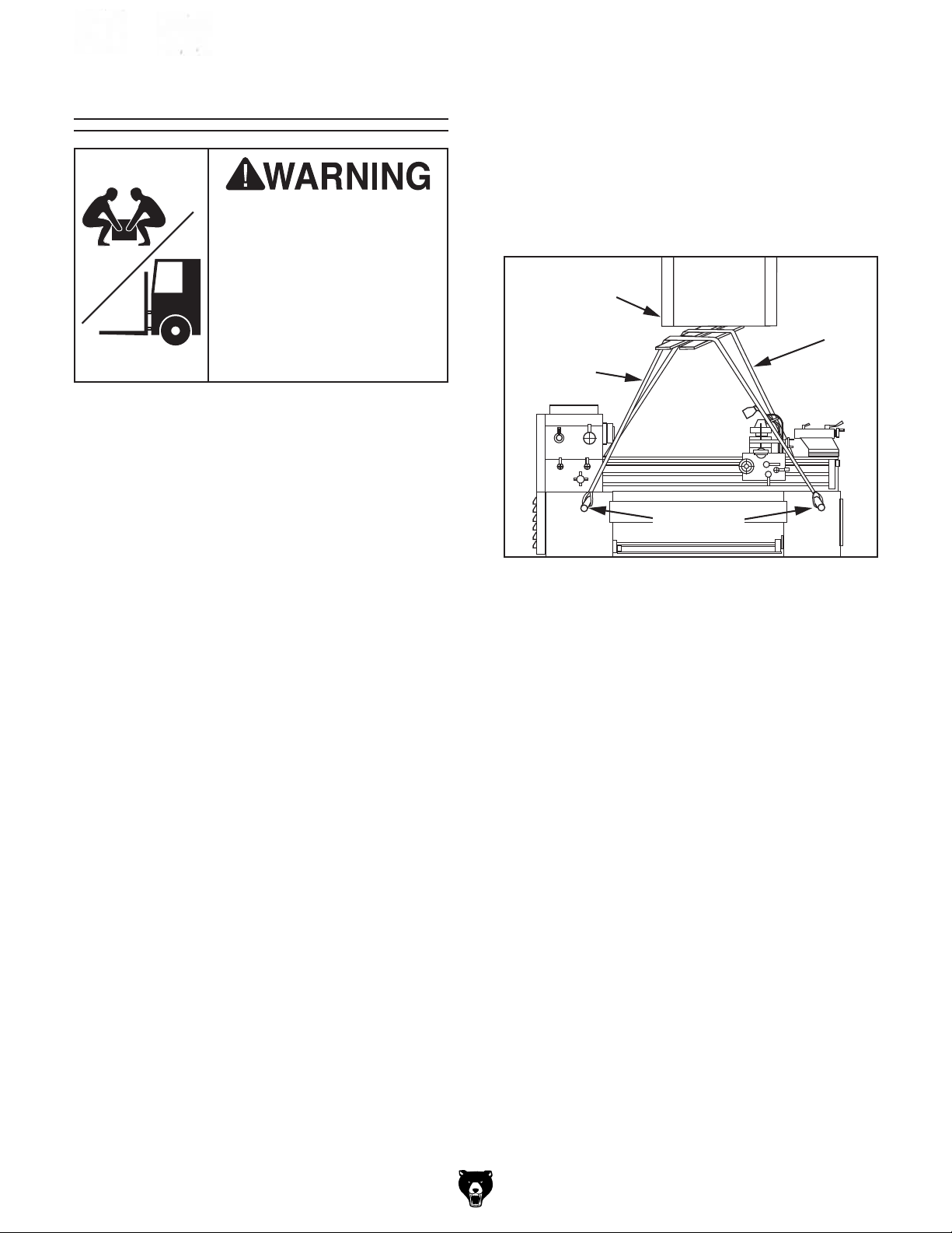
Use Blocks to Space Straps Away
from Control Rod, Feed Rod, Leadscrew &
Prevent Bending During Lifting
Lifting & Placing
HEAVY LIF T!
Straining or crushing injury
may occur from improperly
lifting machine or some of
its parts. To reduce this risk,
get help from other people
and use a fork lift (or other
lifting equipment) rated for
weight of this machine.
Do not attempt to lift or move this lathe without
using the proper lifting equipment (such as forklift
or crane) or the necessary assistance from other
people. Each piece of lifting equipment must be
rated for at least 6800 lbs to support dynamic
loads that may be applied while lifting. Refer to
Needed for Setup on Page 20 for details.
6. Insert round steel bar stock through the four
lifting holes (see Figure 16).
Note: To properly support the lathe and
avoid damaging lathe components, bar stock
should be at least 1" diameter thick and 49"
long, so it projects 14" from both sides of the
lathe when installed.
Power Lifting
Equipment
Rear
Lifting
Strap
Front
Lifting
Strap
Bar Stock
To lift and move the lathe:
1. Remove the shipping crate top and sides,
then remove the small components from the
shipping pallet.
2. Move the lathe to its prepared location while
it is still attached to the shipping pallet.
3. Unbolt the lathe from the shipping pallet.
4. To balance the load for lifting, move the
tailstock and carriage to the extreme right
end of the bedway, then lock them in place.
Note: Before attempting to move the car-
riage, make sure the carriage lock is loose,
the half nut is disengaged, and the power
feed is disengaged (feed selection lever).
5. Remove the splash guard so it does not get
damaged when the lathe is raised.
Figure 16. Example of lathe setup for lifting.
7. Attach the lifting straps to the bar stock and
the power lifting equipment (see Figure 16).
Make sure there is enough space between
the straps and the control rod, feed rod,
leadscrew and electrical cabinet to prevent
putting pressure on these components when
lifting.
8. Raise the lathe a couple of inches and check
the balance of the load. Have two other people carefully steady the lathe to help prevent
it from swinging.
— If the load is not safely balanced, immedi-
ately lower the lathe and resolve the issue
before attempting to lift it again.
9. Raise the lathe enough to clear the shipping
pallet and carefully remove the pallet.
— If you plan to use the included leveling
bolts and hex nuts to level the lathe, install
them now.
-24-
10. Lower the lathe into position.
11. Re-install the splash guard.
Model G0746/G0749 (Mfg. Since 3/13)
Page 27
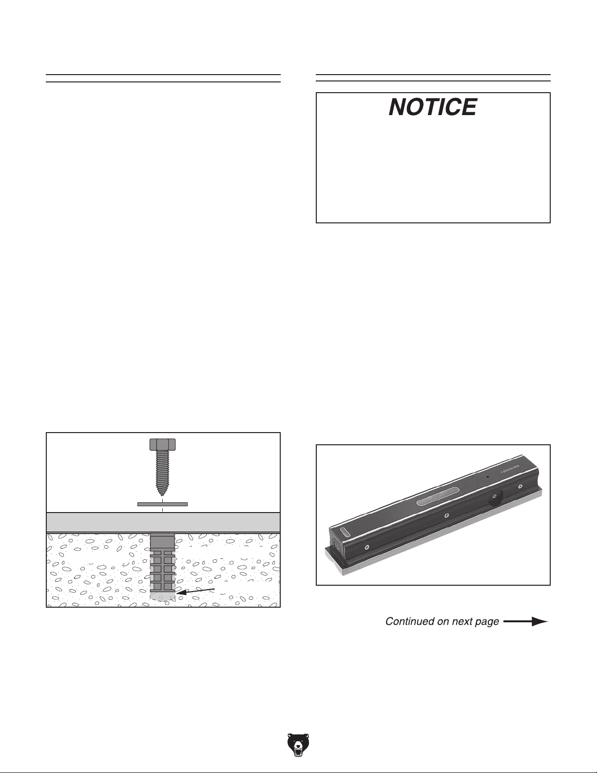
Anchoring machinery to the floor prevents tipping
or shifting and reduces vibration that may occur
during operation, resulting in a machine that runs
slightly quieter and feels more solid.
If the machine will be installed in a commercial or
workplace setting, or if it is permanently connected (hardwired) to the power supply, local codes
may require that it be anchored to the floor.
If not required by any local codes, fastening the
machine to the floor is an optional step. If you
choose not to do this with your machine, we recommend placing it on machine mounts, as these
provide an easy method for leveling and they have
vibration-absorbing pads.
Anchoring to Floor Leveling
For accurate turning results and to prevent
warping the cast iron bed and ways, the
lathe bedways MUST be leveled from sideto-side and from front-to-back on both ends.
Re-check the bedways 24 hours after
installation, two weeks after that, and then
annually to make sure they remain level.
Leveling machinery helps precision components,
such as bedways, remain straight and flat during
the lifespan of the machine. Components on a
machine that is not level may slowly twist due to
the dynamic loads placed on the machine during
Anchoring to Concrete Floors
operation.
Lag shield anchors with lag screws (see below)
are a popular way to anchor machinery to a concrete floor, because the anchors sit flush with the
floor surface, making it easy to unbolt and move
the machine later, if needed. However, anytime
local codes apply, you MUST follow the anchoring
methodology specified by the code.
Lag Screw
Flat Washer
Machine Base
Concrete
Figure 17. Popular method for anchoring
machinery to a concrete floor.
Lag Shield Anchor
Drilled Hole
For best results, use a precision level that is at
least 12" long and sensitive enough to show a
distinct movement when a 0.003" shim (approximately the thickness of one sheet of standard
newspaper) is placed under one end of the level.
See the figure below for an example of a high
precision level offered by Grizzly.
Figure 18. Model H2683 precision level.
Model G0746/G0749 (Mfg. Since 3/13)
-25-
Page 28
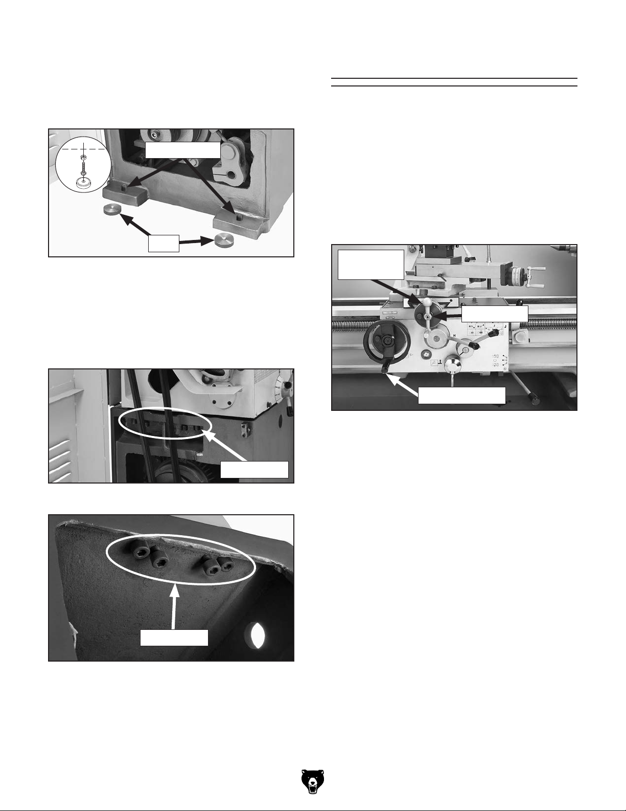
—If using the included leveling pads (see
Figure 19), thread the leveling bolts with
the hex nuts into the bottom of the stand,
place the pads under the bolts, then adjust
them to level the machine.
Assembly
With the exception of the carriage handle and
cross slide handwheel, the lathe is shipped fully
assembled.
Leveling Bolts
x 8
Pads
Figure 19. Leveling pads, bolts (hex nuts not
shown).
For additional leveling, use the jack screws under
the headstock and tailstock (see Figures 20 and
21). To access the tailstock-end jack screws,
remove the coolant motor cover.
Use a 5mm hex wrench to thread the carriage
handle into the carriage handwheel.
Slide the cross slide handwheel onto the shaft
and secure it with the included tapered pin, as
shown in Figure 22.
Cross Slide
Handwheel
Tapered Pin
Carriage Handle
Figure 22. Handwheel handles installed.
Jack Screws
Figure 20. Location of headstock jack screws.
Jack Screws
Figure 21. Tailstock-end jack screws.
— If using mounting hardware that does not
allow for adjustment, level the lathe by
placing metal shims between the lathe
base and the floor before anchoring it.
-26-
Model G0746/G0749 (Mfg. Since 3/13)
Page 29

Lubricating Lathe
GEARBOXES MUST
BE FILLED WITH OIL!
MACHINE MAY NOT BE
SHIPPED WITH OIL!
Requires Oil
Before Operation
or Warranty Will
Be Void.
Power Connection
Electrocution or fire
may occur if machine is
ungrounded, incorrectly
connected to power, or
connected to an undersized
circuit. Use an electrician
or a qualified service
personnel to ensure a safe
power connection.
The headstock, gearbox, and apron oil reservoirs
must have the proper amount of oil in them before
the lathe can be operated.
Damage caused to the bearings and gears from
running the lathe without oil in the reservoirs
will not be covered under warranty. Refer to the
Lubrication section, beginning on Page 67, for
checking and adding oil.
In addition to the reservoirs, we also recommend
that you lubricate all other points on the machine
at this time. To do this, follow the steps provided in
the maintenance schedule on Page 66.
Note: If this lathe was shipped with oil in the res-
ervoirs, do not change that oil until after the Test
Run and Spindle Break-In procedures.
Adding Coolant
Add the coolant of your choice now. For detailed
instructions on where the coolant tank is located
and how to add fluid, refer to Coolant System
Service on Page 72.
Before the machine can be connected to the
power source, an electrical circuit and connection
device must be prepared according to the circuit
requirements on the Page 18, and the machine
must be completely setup and installed in its permanent location.
Once the lathe is connected to the power supply,
the disconnect switch that is installed by the electrician (as recommended) is the primary means
for disconnecting or connecting the machine to
the power source.
Note About Phase Converters: Due to the
startup load from this machine, we do not recommend using a static phase converter to create
3-phase power—as it can quickly decrease the
life of electrical components on this machine. If
you must use a phase converter, only use a rotary
phase converter. Only connect the manufactured
leg or "wild wire" to the L3 terminal (see location in Figure 24 on Page 28). The L3 terminal
can handle power fluctuation because it is wired
directly to the motor.
Model G0746/G0749 (Mfg. Since 3/13)
-27-
Page 30

To connect lathe to power:
1. Make sure the main power switch on the
lathe electrical cabinet is turned to the OFF
position, then open the door.
2. Insert the incoming power wires through the
opening shown in Figure 23.
Opening for
Incoming Power
Test Run
Once the assembly is complete, test run your
machine to make sure it runs properly and is
ready for regular operation.
The test run consists of verifying:
• The motor powers up and runs correctly.
• The motor turns in the correct direction
(machine is not wired out of phase).
• The safety features work correctly.
• The brake system works correctly.
Figure 23. Location of opening in electrical
cabinet for incoming power.
3. Connect the incoming hot wires to the L1,
L2, and L3 terminals, shown in Figure 24.
Connect the incoming ground to the grounding terminal (PE).
L3 L2 L1 PE
Figure 24. Location to connect incoming hot
wires and ground wire.
• The coolant system works correctly.
If you notice an unusual noise or vibration, stop
using the machine immediately, and remedy
before operating it further.
Before starting the lathe, make sure you
have performed the preceding assembly
and adjustment instructions, and you have
read all the documentation provided with the
lathe and are familiar with the various functions and safety features on this machine.
Failure to follow this warning could result in
serious personal injury or even death!
To test run your machine:
1. Make sure the main power switch (see
Figure 25) is turned OFF.
4. Make sure the wires have enough slack so
they are not pulled tight or stretched.
5. Close the main electrical cabinet door.
-28-
Main Power
Switch
Figure 25. Location of the main power switch.
Model G0746/G0749 (Mfg. Since 3/13)
Page 31

2. Read and follow the safety instructions at the
beginning of the manual, take all required
safety precautions, and make sure all previous preparation steps discussed in this
manual have been followed and completed.
6. Set the spindle speed to 24 RPM as follows:
a. Position the spindle range lever straight
up, so it aligns with the arrow on the
headstock (see Figure 27).
3. Clear away all tools and objects used during
assembly, lubrication, and preparation.
4. Make sure that the chuck and jaws, if installed,
are secure.
Note: If a chuck is not installed on the lathe,
you do not need to install one for this test.
5. Push the EMERGENCY STOP button on the
control panel (see Figure 26), and point the
coolant nozzle into the chip pan.
EMERGENCY
Cutting Fluid
Pump Switch
STOP
Button
Power
Lamp
Spindle Range
Lever
Spindle
Range Lever
Pointing Up
Spindle
Speed Lever
Spindle Speed
Lever Set To
“E” (24 RPM)
E
Figure 26. Control panel buttons used in test
run.
Note: In the next step, you may need to rock the
chuck back and forth as you make the adjustments, so that the gears will mesh together.
Figure 27. Spindle speed set to 24 RPM.
b. Position the spindle speed lever so the
"E" is directly under the black arrow on
the headstock (see Figure 27).
7. Make sure the spindle lever is in the middle
(OFF) position to prevent unexpected startup
when power is enabled (see Figure 28).
Spindle
Lever
Figure 28. Spindle lever in middle (OFF)
position.
8. Turn the main power switch ON and reset
the EMERGENCY STOP button by twisting
it clockwise until it pops out. The power lamp
on the control panel should illuminate.
Model G0746/G0749 (Mfg. Since 3/13)
-29-
Page 32

Engaged
Disengaged
Feed Lever
Feed Selection
Lever
9. To ensure the carriage components do not
unexpectedly move during the following steps,
disengage the half nut lever, feed lever, and
feed selection lever (see Figure 29).
Feed
Selection
Feed
Lever
Half Nut
Lever
Disengaged
Halfnut
Lever
Disengaged
Figure 29. Disengaging carriage components.
Engaged
Cross Slide
Carriage
Feed Selection
Lever
Feed
Lever
Lever
— When operating correctly, the lathe runs
smoothly with little or no vibration or rubbing
noises.
— Investigate and correct strange or unusual
noises or vibrations before operating the
machine further. Always disconnect the
machine from power when investigating or
correcting potential problems.
11. With the spindle lever in the down position,
verify the spindle is rotating counterclockwise —
down and toward the front of the lathe.
— If the spindle and chuck are not rotating
counterclockwise, the power supply may
be connected out-of-phase. Stop the
spindle, disconnect lathe from power, then
follow the instructions in the Correcting
Phase Polarity section on Page 19. After
correcting the wiring, repeat Steps 9–11.
12. Press the EMERGENCY STOP button to
turn the lathe OFF, then, without resetting
the EMERGENCY STOP button, try to restart
spindle rotation. The spindle should not start.
— If spindle rotation does start with the
EMERGENCY STOP button pressed in,
the EMERGENCY STOP button safety is
not operating correctly. This safety feature
must operate properly before continuing
operation. Use the spindle lever to stop the
lathe, disconnect it from power, and call
Tech Support for help.
10. Turn the spindle ON by pulling the spindle
lever out and moving it down (see Figure 30).
Verify that the machine is operating correctly.
Spindle
Lever
Figure 30. Spindle lever in down (forward)
position.
-30-
13. Move the spindle lever to the middle (OFF)
position, and reset the EMERGENCY STOP
button by twisting it clockwise until it pops
out.
14. Restart spindle rotation.
15. Push the foot brake. The spindle should
come to a quick stop.
— If the brake pedal has no effect on the
lathe, push the EMERGENCY STOP button and call Tech Support for help.
Model G0746/G0749 (Mfg. Since 3/13)
Page 33

16. Move the spindle lever to the middle (OFF)
Before subjecting the spindle to operational loads,
it is essential to complete the break-in process.
This helps ensure maximum life of spindle bearings and other precision components by thoroughly lubricating them before placing them under
load.
After spindle break-in is complete, we recommend
changing headstock and gearbox oil to remove
any metal particles or debris that are present from
the assembly and break-in process.
The break-in must be performed in succession
with the
manual, as the steps in that procedure prepare
the lathe controls for the break-in process.
Before subjecting the spindle to operational loads,
it is essential to complete the break-in process.
This helps ensure maximum life of spindle bear-
ings and other precision components by thor-
oughly lubricating them before placing them under
load.
After spindle break-in is complete, we recommend
changing headstock and gearbox oil to remove
any metal particles or debris that are present from
the assembly and break-in process.
The break-in must be performed in succession
with the Tes t Run procedure described in this
manual, as the steps in that procedure prepare
the lathe controls for the break-in process.
dently of the Test Run section. The lathe
are set differently than instructed in that
position. Open the end-gear cover on the left
side of the headstock. This activates a safety
switch that should prevent the spindle from
starting while this cover is open.
DO NOT perform this procedure indepen-
could be seriously damaged if the controls
Note: Remove the cap screw on the front of
the cover to open it.
17. Stand away from all the exposed gears on
the side of the headstock, and attempt to start
spindle rotation. The spindle should not start.
— If spindle rotation does start with the end-
gear cover open, the safety switch is not
operating correctly. This safety feature
must operate properly before continuing
operation. Press the EMERGENCY STOP
button to turn the lathe OFF, disconnect it
from power, and call Tech Support for help.
18. Move the spindle lever to the OFF position,
then close the end-gear cover.
19. Use the cutting fluid pump switch on the control panel to start the pump (see Figure 26 on
Page 29), then open the valve. Verify that the
cutting fluid flows from the nozzle, then turn
the pump OFF.
section.
To perform the spindle break-in:
1. Successfully complete the Test Run proce-
dure beginning on Page 28.
2. Run the lathe for 5 minutes in each direction
at 24 RPM (first forward and then reverse).
3. Repeat Step 2 for the remaining RPM ranges, progressively increasing in RPM. When
these steps are complete, the lathe is broken
in.
Congratulations! Spindle break-in is complete. We
recommend changing the headstock and gearbox
oil before operating the machine further (refer to
Lubrication on Page 67).
Recommended
Congratulations! The test run is complete. Perform
the following Spindle Break-In procedure.
Spindle Break-In
Test Run procedure described in this
Adjustments
The following adjustments have been made at the
factory. However, because of the many variables
involved with shipping, we recommend you verify
these adjustments to ensure the best results:
Factory adjustments that should be verified:
• Tailstock alignment (see Page 42).
• Cross slide and compound slide backlash
adjustment (see Page 78).
• Gib adjustments (see Page 79).
Model G0746/G0749 (Mfg. Since 3/13)
-31-
Page 34

SECTION 4: OPERATIONS
The purpose of this overview is to provide the novice machine operator with a basic understanding
of how the machine is used during operation, so
the
discussed later
in this manual
Due to the generic nature of this overview, it is
not intended to be an instructional guide. To learn
more about specific operations, read this entire
manual and
rienced
research outside of this manual by reading "howto" books, trade magazines, or websites.
To reduce your risk of
serious injury, read this
entire manual BEFORE
Operation Overview
machine controls/components
are easier to understand.
To complete a typical operation, the operator
does the following:
1. Puts on safety glasses, rolls up sleeves,
removes jewelry, and secures any clothing,
jewelry, or hair that could get entangled in
moving parts.
2. Examines the workpiece to make sure it is
suitable for turning, then securely mounts it
in the lathe.
seek additional training from expe
machine operators, and do additional
using machine.
To reduce the risk of
eye injury from flying
chips always wear safety
glasses.
If you are not experienced with this type
of machine, WE STRONGLY RECOMMEND
that you seek additional training outside of
this manual. Read books/magazines or get
formal training before beginning any projects. Regardless of the content in this section, Grizzly Industrial will not be held liable
for accidents caused by lack of training.
3. Installs the tooling, aligns it with the workpiece,
then backs it away to establish a safe startup
clearance.
4. Removes all setup tools from the lathe.
5. Checks for safe clearances by rotating the
workpiece by hand at least one full revolution.
6. Moves slides to where they will be used during operation.
7. Sets the correct spindle speed for the operation.
8. If using power feed, selects the proper feed
rate for the operation.
9. Turns the main power switch ON and resets
the EMERGENCY STOP button.
10. Uses the spindle lever to start spindle rotation.
11. Uses the carriage handwheels or power feed
options to move the tooling into the workpiece
for operations.
12. When finished cutting, moves the spindle
lever to the OFF position, presses the foot
brake to completely stop the spindle, then
removes the workpiece.
-32-
Model G0746/G0749 (Mfg. Since 3/13)
Page 35

Chuck & Plate
This lathe is equipped with a D1-type spindle
nose. This type of spindle uses camlocks that are
adjusted with a chuck key to securely mount a
chuck or faceplate with repeatable precision and
ease.
This lathe ships with the 3-jaw chuck installed.
This is a scroll-type chuck where all three jaws
move in unison when the chuck key is used.
The included 4-jaw chuck features independent
jaws, which are used for square or unevenlyshaped stock, and to mount work that needs to be
adjusted to near zero total indicated runout.
The included faceplate has slots for T-bolts that
hold standard or custom clamping hardware. With
the correct clamping hardware, a faceplate offers
a wide range of uses, including machining nonconcentric workpieces, straight turning between
centers, off-center turning, and boring.
3. Install a cap screw in the hole next to each
Note: It is normal for studs to have a small amount
of play or looseness after installing and tightening
the cap screws.
To install the camlock studs:
1.
2.
alignment groove is positioned over the hole.
Camlock Stud
Mounting
Never use spindle speeds faster than the
chuck RPM rating or the safe limits of
your workpiece. Excessive spindle speeds
greatly increase the risk of the workpiece or
chuck being thrown from the machine with
deadly force!
Installation
This section provides information about how to
install and adjust the camlock studs so the chuck,
faceplate, and drive plate properly mount to the
spindle.
Note: You can skip this section if the camlock
studs are already installed.
Lightly oil the threads of each stud.
Thread the studs in until the datum line is
flush with or just above the surface, and the
Alignment
Groove
Cap
Screw
Datum Line
Flush with
Surface
The included drive plate has drive pins, which are
used in conjunction with a straight lathe dog for
turning workpieces between centers.
Refer to Camlock Stud Installation for installing camlock studs on the chucks, faceplate, and drive plate.
Model G0746/G0749 (Mfg. Since 3/13)
Figure 31. Camlock stud installation.
stud. These cap screws prevent the studs
from rotating so they properly engage with
the camlock during installation.
-33-
Page 36

Installation &
Because chucks are heavy and often awkward
to hold, some kind of lifting, support, or protective device should be used during installation or
removal. The weight and size of the chuck will
determine the appropriate device to use (refer to
the following figure for examples).
Pre-Threaded Hole
for Lifting Eye
Way Slot
Jaw Slot
Plywood & 2x4
Chuck Cradle
Plywood Chuck Cradle
(Straight Cuts)
Plywood Chuck Cradle
(Curved Cuts)
Fabricated Steel
Lifting Hook
Solid Block
Chuck Cradle
Plywood Protection
Plate for Chucks
Installed by Hand
MEDIUM-SIZE, HEAVY CHUCKS
LARGE, VERY HEAVY CHUCKS
SMALL, LIGHTWEIGHT CHUCKS
To ensure accurate work, it is extremely important
to make sure the spindle nose and chuck mating
surfaces/tapers are clean. Even a small amount of
lint or debris can affect accuracy.
The chuck is properly installed when all camlocks
are tight, the spindle and chuck tapers firmly
lock together, and the back of the chuck is firmly
seated against the face of the spindle all the way
around—without any gaps.
To install the chuck:
1.
2.
Installation & Removal Devices
3.
4.
Avoid inserting the studs by pivoting them in from an angle or rotating the
spindle. This can damage studs or spindle
cam holes.
Removal Devices
Dropping a chuck can result in amputation,
serious crushing injuries, or property damage. Always use a support or protective
device to reduce this risk during installation
or removal.
Chuck Installation
DISCONNECT LATHE FROM POWER!
Use an appropriate lifting, support, or protec-
tive device to protect the ways and support
the chuck during the installation process
(refer to the
section on the previous page).
Figure 32. Examples of common devices used
during chuck installation and removal.
-34-
Clean and lightly oil the camlock studs, then
thoroughly clean the mating surfaces of the
spindle and chuck.
Install the chuck by inserting the camlock
studs straight into the spindle cam holes.
Important:
INCORRECTCORRECT
Figure 33. Inserting camlock studs into spindle
cam holes.
Model G0746/G0749 (Mfg. Since 3/13)
Page 37

5. Incrementally tighten the camlocks in a crisscross or star pattern to ensure that the chuck
seats evenly against the spindle.
6.
nose, as shown in the following figure.
— If the cam line is NOT between the "V"
positions on the chuck.
Lightly stamp registration marks across the
mating seams of chuck components
marks will help you re-install the chuck in the
same position after removal, which ensures
consistent chuck balance and turning results, and
allows the same camlocks and studs to operate
together for consistent locking and unlocking.
7. Verify that the chuck fits the spindle properly
by checking for any gaps between the mating
8.
our Tech Support.
surfaces.
When the chuck is fully seated and all the
camlocks are tight, verify that the cam line
is between the two “V” marks on the spindle
Cam line between “V”s
Figure 34. Cam line positioned between the "V"
marks after the camlocks are fully tightened.
marks when the camlock is tight, the stud
may be installed at the incorrect height.
To fix this, adjust the stud height as
shown in the following figure. Make sure
to re-install the stud cap screw afterward.
—If there is not a gap, proceed to Step 8.
—If there is a gap, remove the chuck, re-
clean the mating surfaces carefully, and
re-install. If the problem persists, contact
our Tech Support.
Verify that the chuck/spindle tapers are seat-
ed firmly together by removing the chuck,
per the Chuck Removal instructions, and
pay close attention to how easily the tapers
release.
—If it was necessary to bump the chuck or
use a mallet to release the tapers, then
they are seating together properly.
—If the tapers released easily with little
intervention, they are not seated together
firmly as required. Remove the chuck, reclean the mating surfaces carefully, and
re-install. If the problem persists, contact
Registration Marks
— If adjusting the stud height does not
correct the problem, try swapping stud
INCORRECT INCORRECT
Stud Too High:
Turn In
One-Turn
Figure 35. Correcting an improperly installed
stud.
Model G0746/G0749 (Mfg. Since 3/13)
Stud Too Low:
Turn Out
One-Turn
Spindle & Chuck
Camlock
Registration Marks
Spindle
Figure 36. Registration mark locations.
. These
-35-
Page 38

Chuck Removal
To remove the chuck:
Installation & Removal
as shown below.
Tip: Camlocks can become very tight. A
cheater pipe may be used as a last resort to
add leverage when loosening. After loosening, you may need to wiggle the chuck key in
4.
5.
— If the chuck does not immediately come off,
rotate it approximately 60° and tap it again.
spindle are proper aligned for removal.
This 3-jaw scroll-type chuck has an internal scrollgear
djusted
with the chuck key
cylindrical
parts on-center with the axis of spindle rotation
and can be
at high speeds if the workpiece
is properly clamped and balanced.
Never mix jaw types or
positions to
accommodate an odd-shaped workpiece.
he
chuck will spin out of balance an
may throw the
workpiece
Instead, use an independent jaw chuck
or a faceplate.
1. DISCONNECT LATHE FROM POWER!
2. Use an appropriate lifting, support, or protec-
tive device to protect the ways and support
the chuck (refer to
Devices section for more details).
Scroll Chuck
Clamping
that moves all jaws in unison when a
. This chuck holds
rotated
3. Loosen the camlocks by turning the key
counterclockwise until each cam line is
aligned with its corresponding spindle mark,
Cam line and spindle mark aligned
Figure 37. Camlock is fully loosened when the
cam line is aligned with the spindle mark.
the camlock to fully disengage the stud.
Using a dead blow hammer or other soft
mallet, lightly tap around the outer circumference of the chuck body to loosen it from the
spindle.
Remove the chuck from the spindle, using
a light rocking motion to carefully slide the
studs out of the cam holes.
Make sure all the marks on the cams and
-36-
T
d
!
Safer Inside
Jaw Use
CORRECT
Safer Outside
Jaw Use
CORRECT
Safer Outside
Jaw Use
CORRECT
Safer Inside
Jaw Use
CORRECT
Bar Stock
Unsafe Jaw Position and
Poor Scroll Gear Engagement
Shallow
Bar Stock
Shallow
Bar Stock
Unsafe Jaw
Position
Cylinder
Poor Scroll
Gear Engagement
Insufficient
Jaw Clamping
Unsafe Inside
Unsafe Jaw Position
Unstable
Workpiece
INCORRECT
Poor Grip
Workpiece
INCORRECT
Jaw Use
Poor Scroll
Gear
Engagement
INCORRECT
INCORRECT
Unstable
Figure 38. Jaw selection and workpiece holding.
Model G0746/G0749 (Mfg. Since 3/13)
Page 39

Changing Jaw Set
The 3-jaw scroll chuck included with the lathe
features inside and outside
sets
move in unison to
center a concentric workpiece.
When installing the jaws
sure they are installed correctly. Incorrect installation will result in jaws that do not converge evenly
and are unable to securely clamp a workpiece.
Jaws are numbered from 1–3 (see Figure below).
The number is typically stamped on the side
or bottom. Jaws are designed to be installed in
numerical order in the jaw guides, so they will hold
a concentric workpiece evenly.
To change the jaw set:
1.
2.
3.
4.
5.
n a safe
6.
enter a jaw guide (see Figure 38).
7. Insert jaw #1 into the jaw guide and hold the
8
9
— If installed correctly, the jaws will converge
— If the jaws do not converge evenly, remove
sequentially 1–3,
and make sure each one engages with the
tion.
DISCONNECT LATHE FROM POWER!
hardened steel jaw
(see Figure below), which
, it is important to make
Inside SetOutside Set
Figure 39. Chuck and jaw selection.
Place a piece of plywood over the bedways to
protect them from potential damage.
Insert the chuck key and turn it counterclock-
wise to back the jaws out and remove them.
Use mineral spirits to clean the debris and
grime from the jaws and chuck jaw guides.
Apply a thin coat of white lithium grease to
surfaces of removed jaw set. Store i
place free from moisture and abrasives.
Rotate chuck key clockwise until you see
the tip of the scroll-gear lead thread begin to
1
Lead Thread
Jaw Numbers
1
2
Figure 40. Jaw guide and jaw numbers.
Model G0746/G0749 (Mfg. Since 3/13)
3
Jaw Guides
Figure 41. Lead thread on scroll gear.
jaw against the scroll-gear.
. Rotate the chuck key clockwise one turn to
engage the tip of the scroll-gear lead thread
into the jaw. Pull the jaw; it should be locked
into the jaw guide.
. Install the remaining jaws in numerical order,
in the same manner.
evenly at the center of the chuck.
them. Re-install the jaws
scroll-gear lead thread during its first rota-
-37-
Page 40

4-Jaw Chuck
Refer to the Chuck Installation or Chuck
Removal
removing the 4-jaw chuck.
The 4-jaw chuck features independently adjustable jaws for holding non-concentric or off-center
workpieces. Each jaw can be independently
removed from the chuck body and reversed for a
wide range of work holding versatility.
Mounting Workpiece
1.
2.
3.
workpiece will lay flat against the chuck face,
4.
tered in the chuck.
5. Tighten each jaw in small increments. After
tightening the remaining jaws in an opposing
in the Figure below.
6. After the workpiece is held in place by the
tioned (see below for an example).
sections for instructions on installing or
you have adjusted the first jaw, continue
sequence, as shown by the sequential order
Because of the dynamic forces involved in
machining a non-concentric or off-center
workpiece, always use a low spindle speed
to reduce risk of the workpiece coming loose
and being thrown from the lathe, which could
cause death or serious personal injury.
DISCONNECT LATHE FROM POWER!
Place a chuck cradle or plywood on the bed-
way below the chuck to protect the bedway
surfaces.
1
4
Figure 42. 4-jaw tightening sequence.
jaws, use a dial indicator to make sure the
workpiece is centered in the chuck.
— If the workpiece is not correctly centered,
make fine adjustments by slightly loosening one jaw and tightening the opposing
jaw until the workpiece is correctly posi-
3
Workpiece
Center Point
2
Use the chuck key to open each jaw so the
jaw steps, or into the spindle opening.
With help from another person or a holding
device, position the workpiece so it is cen-
-38-
Figure 43. Generic picture of non-cylindrical
workpiece correctly mounted on the 4-jaw chuck.
Model G0746/G0749 (Mfg. Since 3/13)
Page 41

To mount a non-concentric workpiece to the
faceplate:
1.
2.
3.
If necessary, use counter-weights to balance
the assembly and use a dial indicator to make
sure that the workpiece is properly positioned
for your operation.
Refer to the prior Chuck Installation and Chuck
Removal
removing the faceplate.
The faceplate included with your lathe can be
used for a wide range of operations, including
machining non-concentric workpieces, straight
turning between centers, off-center turning, and
boring.
The tools needed for mounting a workpiece will
vary depending on the type of setup you have.
Drive Plate
Refer to the prior Chuck Installation and Chuck
Removal sections for instructions on installing or
removing the drive plate.
The drive plate included with your lathe is used
for straight turning between centers. The Figure
below shows a straight lathe dog (not included)
attached to the workpiece. The end of the dog
rests against a drive plate pin.
Failure to properly secure a workpiece to
the faceplate could cause the workpiece
to be thrown from the lathe with deadly
force. To reduce this risk, use a minimum
of THREE independent clamping devices to
hold the workpiece onto the faceplate.
DISCONNECT LATHE FROM POWER!
Drive Plate
Chuck
Figure 44. Typical drive plate setup.
Pin
Straight
Lathe Dog
Faceplate
sections for instructions on installing or
Workpiece
Quill
Protect the bedway with a piece of plywood.
With help from another person or a holding
device to support the workpiece, position it
onto the faceplate and clamp it in place with
a minimum of three independent clamping
devices (see Figure below for an example).
Be sure to take into account the rotational
and cutting forces that will be applied to the
workpiece when clamping it to the faceplate.
Non-Cylindrical
Workpiece
Machining non-concentric workpieces at
high speeds could cause the workpiece to
be thrown from the lathe with deadly force.
To reduce this risk, do not exceed 395 RPM,
and use counter-weights to balance the
faceplate or workpiece.
Model G0746/G0749 (Mfg. Since 3/13)
Clamp
Faceplate
Figure 45. Generic picture of workpiece clamped
in a faceplate.
-39-
Page 42

1. Move the quill lock lever away from the spin-
2.
3.
secure the quill in place.
1. Pull the tailstock lock lever to unlock the tail-
2.
3.
stock against the bedway.
The tailstock (see Figure below) is typically used
to support long workpieces by means of a live or
dead center (refer to
in the following section). It can also be used to hold a drill or chuck to
bore holes in the center of a part. Custom arbors
and tapers can also be cut on your lathe by using
the offset tailstock adjustment.
Quill Lock
Lever
Tailstock
Centers
Tailstock Lock
Lever
Quill
Handwheel
Using Quill
dle to unlock the quill.
Turn the quill handwheel clockwise to move
the quill toward the spindle or counterclockwise to move it away from it.
Move the lock lever toward the spindle to
Installing Tooling
This tailstock uses a quill with an MT#5 taper
that accepts tapered arbors and drill bits (see the
Figures below for examples).
Figure 46. Tailstock and quill lock levers in
locked position.
Graduated Dial
Increments ................................................. 0.001"
One Full Revolution ................................... 0.200"
Increments on Quill
Inch .............................0"–4
Metric ................... 0–115mm in 1mm Increments
3
⁄4" in 1⁄8" Increments
Positioning Tailstock
stock from the bedway.
Solid
End
Figure 47. Types of tapered arbors and tooling.
Open
End
Solid
End
Screw
End
Tang
Slide the tailstock to the desired position.
Push the tailstock lock lever to lock the tail-
-40-
Figure 48. Example photos of inserting tools into
the tailstock.
Model G0746/G0749 (Mfg. Since 3/13)
Page 43

To install tooling in the tailstock:
1.
2. Thoroughly clean and dry the tapered mating
3.
into the quill. Check to see if it is firmly seated
4.
5.
lever, then turn the quill handwheel clockwise
to feed the tool into the workpiece.
1. Use a shop rag to hold the tool.
2.
until the tool is forced out of the quill.
The tailstock can be offset from the spindle centerline for turning tapers. Move the tailstock top
casting toward the front of the lathe to machine a
taper at the tailstock end. Conversely, move the
tailstock top casting toward the back of the lathe
to machine a taper at the spindle end
Note: If the tooling has an open hole in the end,
then a screw can be threaded into the end of the
tool to provide a solid surface for the quill pin to
push against when the quill is retracted for tool
removal. Otherwise, removal of such tooling may
be difficult.
With the tailstock locked in place, unlock the
quill, then use the handwheel to extend it
approximately 1".
surfaces of the quill and the center, making
sure that no lint or oil remains on the tapers.
Note: The marks on the offset indicator (see
Figure 49) are arbitrary. For a precise offset, use
a dial indicator to check quill movement while
adjusting the screws.
Adjustment
Set Screw (1 of 2)
Offset
Indicator
With a firm and quick motion, insert the tool
by attempting to twist it—a firmly seated tool
will not twist.
Unlock the tailstock and move it until the tip
of the tool is close to, but not touching, the
workpiece, then re-lock the tailstock.
Start spindle rotation, unlock the quill lock
Removing Tooling
Rotate the quill handwheel counterclockwise
Offsetting Tailstock
Figure 49. Left offset adjustment.
Tools Needed Qty
Hex Wrench 6mm .............................................. 1
To offset the tailstock:
1. Loosen the tailstock lock lever to release the
clamping pressure between the top and bottom castings.
2. Rotate the adjustment set screws in opposite
directions for the desired offset (see the illustration in Figure 50).
Turn
CCW
Turn
CW
Turn
CW
Turn
CCW
.
Model G0746/G0749 (Mfg. Since 3/13)
Figure 50. Example of set screw adjustment in
relation to tailstock movement.
3. Re-tighten the tailstock lock lever to secure
the offset.
-41-
Page 44

Aligning Tailstock to Spindle
This is an essential adjustment that should be verified or performed each time the tailstock is used
to turn concentric workpieces between centers
or immediately after offsetting the tailstock when
turning a taper. If the tailstock is not aligned with
the spindle centerline when it is supposed to be,
turning results will be inaccurate along the length
of the workpiece.
To align the tailstock to the spindle centerline:
1.
condition before continuing with this proce-
section in this
2.
3.
illustrated in the Figure below.
Note: As long as this dead center remains in
the chuck, the point of the center will remain
true to the spindle centerline. The point will
have to be refinished whenever the center is
4.
5.
, then mount it between the centers as
shown in the Figure below.
6. Turn 0.010" off the stock diameter.
7.
Note: If necessary in the following step, refer
subsection for
Centerline
Items Needed Qty
Hex Wrench 6mm .............................................. 1
Round Stock 2" x 6" .......................................... 2
Precision Level .................................................. 1
Use the precision level to make sure the bed-
way is level from side to side and from front
to back.
removed and then returned to the chuck.
Install a center in the tailstock.
Attach a lathe dog to the test stock from
Step 2
— If the bedway is not level, correct this
dure (refer to the Leveling
manual).
Center drill both ends of one piece of round
stock, then set it aside for use in Step 5.
Use the other piece of round stock to make
a dead center, and turn it to a 60° point, as
Figure 52. Example photo of stock mounted
between the centers.
Mount a test or dial indicator so that the
plunger is on the tailstock quill.
to the Offsetting Tailstock
-42-
Figure 51. Turning a dead center.
Model G0746/G0749 (Mfg. Since 3/13)
Page 45

8. Use calipers to measure both ends of the
workpiece.
of
taper, as shown in the Figure below.
— If the test stock is thinner at the tailstock
of
taper, as shown in the Figure below.
9. Repeat Steps 6–8 until the desired accuracy
Centers
— If the test stock is thicker at the tailstock
end, move the tailstock toward the front
the lathe 1⁄2 the distance of the amount of
Move tailstock toward
front of lathe
amount of taper.
Looking down from above.
Figure 53. Adjust tailstock toward the operator.
end, move the tailstock toward the back
the lathe 1⁄2 the distance of the amount of
1
/2 the
Figure 55 shows the MT#5 dead centers included
with the lathe. In addition, an MT#7–MT#5 tapered
spindle sleeve is included for mounting in the
spindle.
Spindle
Sleeve
Dead
Centers
Figure 55. Adapter sleeve and dead centers.
Dead Centers
A dead center is a one-piece center that does not
rotate with the workpiece and is used to support
long, slender workpieces in the tailstock.
Looking down from above.
Move tailstock toward
back of lathe 1/2 the
amount of taper.
Figure 54. Adjust tailstock away from the
operator.
A carbide-tipped dead center (not included) can
better withstand the effects of friction than a typical dead center and is best used in the tailstock
where the workpiece will rotate against it. The tip
of a dead center must be generously lubricated
during the operation to avoid premature wear and
maximize smooth operation. Using low spindle
speeds will also reduce the heat and wear from
friction.
Use the dead center in the spindle for operations
where the workpiece rotates with the center and
does not generate friction.
Model G0746/G0749 (Mfg. Since 3/13)
-43-
Page 46

To remove the sleeve and center from the spindle,
insert a piece of round bar stock (or similar)
through the outside end of the spindle. Have
another person hold onto the sleeve and center
with a gloved hand or shop rag, then tap the bar
stock to knock the sleeve loose.
Either a carbide-tipped dead center or live center
can be used in the tailstock. Mounting instructions
are the same for both. The
shows
an example photo of a dead center mounted in a
To mount a center in the tailstock:
1.
2.
center, making sure that no lint or oil remains
on the tapers.
1. DISCONNECT LATHE FROM POWER!
2.
and the
center, making sure that no lint or oil remains
Note: This will prevent the tapered surfaces
from seizing due to operational pressures,
which could make it very difficult to remove
3.
onto the spindle, whichever is correct for your
4.
The
of a dead center installed in the spindle, using
a lathe dog and faceplate for turning between
Live Centers
A live center (not included) has bearings that
allow the center
together; it can be installed in the tailstock quill for
higher speeds.
tip and the workpiece to rotate
Mounting Dead Center in Spindle
Thoroughly clean and dry all threads and
mating surfaces of the spindle bore
on these surfaces.
Removing Center from Spindle
Mounting Center in Tailstock
Figure below
the center.
Mount the chuck, faceplate, or drive plate
operation.
Insert the center into the spindle bore through
the chuck, faceplate, or drive plate.
Figure below shows an example photo
centers.
Dead Center
Carbide-Tipped
Dead Center
Figure 57. Example photo of using a carbide-
tipped dead center installed in the tailstock.
To avoid premature wear of the dead center
or damage to the workpiece, use low spindle
speeds and keep the tip of the dead center
mounted in the tailstock well lubricated.
-44-
Lathe
Dog
Figure 56. Example photo of using a dead
center with a faceplate and lathe dog.
DISCONNECT LATHE FROM POWER!
Thoroughly clean and dry the tapered mating
surfaces of the tailstock quill bore and the
Model G0746/G0749 (Mfg. Since 3/13)
Page 47

Mounting Workpiece Between
3. Use the quill handwheel to feed the quill out
from the casting approximately 1”.
4. Insert the center into the tailstock quill.
5.
Note: Only apply enough pressure with the
tailstock quill to securely mount the workpiece between centers. Avoid overtightening
the center against the workpiece, or it may
become difficult to remove later, and it will
result in excessive friction and heat, which
may damage the workpiece and center.
To remove the center from the quill, hold onto it
with a gloved hand or shop rag, then rotate the
quill handwheel counterclockwise to draw the quill
back into the casting until the center releases.
1. DISCONNECT LATHE FROM POWER!
2.
3.
4.
5.
Figure below).
Note: Only apply enough pressure to securely
mount the workpiece between centers. Avoid
over-tightening the center against the workpiece,
or it may become difficult to remove later. Also,
over-tightening will result in excessive friction and
heat, which may damage the workpiece or center.
Centers
Note: The maximum quill travel is 4
we do not recommend extending the quill
more than 2" or stability and accuracy will be
reduced.
Seat the center firmly into the quill during
workpiece installation by rotating the quill
handwheel clockwise to apply pressure with
the center engaged in the center hole in the
workpiece.
3⁄4", but
Removing Center from Tailstock
Drill center holes in both ends of the work-
piece.
Install a dead center in the spindle with a
lathe dog and a chuck, faceplate or drive
plate, then install a live center or carbidetipped dead center in the tailstock.
Lubricate the workpiece center holes, then
mount it between the centers and hold it in
place with light pressure from the tailstock
center.
Seat the center firmly into the quill by rotating
the quill handwheel clockwise to apply pressure against the workpiece (see example in
Model G0746/G0749 (Mfg. Since 3/13)
Figure 58. Example photo of a workpiece
mounted between the centers.
-45-
Page 48

Steady Rest
The steady rest supports long shafts and can be
mounted anywhere along the length of the bedway
Familiarize yourself with the steady rest components shown below
controls.
3. Position the steady rest with the base clamp
where required to properly support the
workpiece, then tighten the bottom hex nut
shown in Figure 59 to secure it in place.
.
to better understand the
Tools Needed Qty
Open-End Wrench 24mm .................................. 1
Open-End Wrench 36mm ................................. 1
Finger
Adjustment
Knob
Finger
Hex Nut
Thumb
Knob
4. Loosen the hex nut that secures the top half
of the steady rest and open the top, as shown
in Figure 60.
Figure 60. Workpiece mounted in the steady
rest.
5. Loosen the three thumb knobs so the finger
positions can be adjusted.
Hex Nut
Figure 59. Steady rest components.
To install and use the steady rest:
1. DISCONNECT LATHE FROM POWER!
2. Thoroughly clean all mating surfaces, then
place the steady rest base on the bedways
so the triangular notch fits over the bedway
prism.
6. Use the finger adjustment knobs to position
the bottom two fingers so they barely touch
the workpiece, as shown in Figure 60.
7. Close the steady rest, then use the finger
adjustment knobs to adjust all the finger tips
so they just touch the workpiece without
causing deflection.
Note: The finger tips should properly support
the workpiece along the spindle centerline
while still allowing it to freely rotate.
8. Tighten the thumb knobs to secure the set-
tings.
Note: To reduce the effects of friction, lubricate
the fingers with anti-seize lubricant during operation.
-46-
Model G0746/G0749 (Mfg. Since 3/13)
Page 49

Follow Rest Carriage & Slide
The follow rest mounts to the saddle with two hex
bolts (see Figure 61). It is used on long, slender
parts to prevent workpiece deflection from the
pressure of the cutting tool during operation.
Adjust the follow rest fingers in the same manner
as the those on the steady rest.
Locks
The carriage, cross slide, and compound rest
have locks that can be tightened to provide additional rigidity during operation, especially during
heavy cuts.
Note: To reduce the effects of friction, lubricate
the finger tips with generous anti-sieze lubricant
during operation.
Tools Needed Qty
Open-End Wrench 24mm .................................. 1
Fingers
Hex
Bolts
Figure 61. Follow rest attachment.
See Figures 62–63 to identify the locations of the
locks for each device.
Tools Needed Qty
Open-End Wrench 13mm .................................. 1
Carriage
Lock
Cross Slide
Lock
Figure 62. Location of carriage and cross slide
locks.
Model G0746/G0749 (Mfg. Since 3/13)
Compound Rest
Lock
Figure 63. Location of compound rest lock.
-47-
Page 50

Compound Rest
The four-way tool post is mounted on top of the
compound rest
tools
Each tool can be quickly indexed to the workpiece
by
rotating the tool post
to the desired position
handle to lock the tool into position.
2
two
3.
To install a tool in the tool post:
1
Figure
below).
The compound rest handwheel has an indirectread graduated scale. This means that the distance shown on the scale represents the actual
distance the cutting tool moves. The base of the
compound rest has another graduated scale used
for setting the cutting tool to a specific angle.
Graduated Dial
Increments .................................0.002" (0.05mm)
One Full Revolution ........................0.200" (5mm)
Tool Needed Qty
Wrench 19mm ................................................... 1
To set the compound rest at a certain angle:
Four-Way Tool Post
and allows a maximum of four
to be loaded simultaneously.
loosening the top handle,
, then re-tightening the
Installing Tool
Tool Needed Qty
Tool Post T-Wrench ........................................... 1
1. Loosen the four hex nuts at the base of the
compound rest (see Figure 64).
Hex Nuts
(2 of 4)
Angle Scale
Figure 64. Compound rest angle adjustments.
2. Rotate the rest to the desired angle, as indi-
cated by the scale at the base, then retighten
the four hex nuts.
Tip: The first time you set the angle of the
compound rest for cutting threads, mark the
location on the cross slide as a quick reference point. This will allow you to quickly
return the compound rest to that exact angle
the next time you need to cut threads.
-48-
Compound
Rest
. Adjust the tool post bolts so that the cutting
tool can fit underneath them (see
Tool Post
Bolt
Cutting
Tool
Figure 65. Example of tool mounted in tool post.
Over-extending a cutting tool from the post
will increase the risk of tool chatter, breakage,
or tool loosening during operation, which
could cause metal pieces to be thrown at
the operator or bystanders with great force.
DO NOT extend a cutting tool more than 2.5
times the width of its cross-section (e.g.,
2.5 x 0.5" = 1.25").
. Firmly secure the cutting tool with at least
tool post bolts.
Check and adjust cutting tool to spindle cen-
terline, as instructed in the next subsection.
Model G0746/G0749 (Mfg. Since 3/13)
Page 51

Aligning Cutting Tool with Spindle
For most operations, the cutting tool tip should be
aligned with the
centerline, as illustrated in
the Figure below.
There are a number of ways to check and align
the cutting tool to the spindle centerline. If necessary, you can raise the cutting tool by placing
steel shims underneath it. The shims should be
as long and as wide as the cutting tool to properly
support it.
Below are two common methods:
• Move the tailstock center over the cross slide
to measure the distance
cutting tool height so
•
tailstock
Aligning Tailstock To Spindle Centerline
in this manual for detailed instructions).
To align the cutting tool with the tailstock
center:
1.
secure the post so the tool faces the tailstock.
2.
3.
4.
with the center tip, as illustrated below.
Centerline
spindle
Tools Needed Qty
Tool Post T-Wrench ........................................... 1
Steel Shims ....................................... As Needed
Cutting Tool ....................................................... 1
Tailstock Center ................................................. 1
Cutting
Tool
Figure 66. Cutting tool aligned with spindle
centerline (viewed from tailstock).
Spindle
Center
Line
Mount the cutting tool in the tool post, then
Install a center in the tailstock, and position
the center tip near the cutting tool tip.
Lock the tailstock and quill in place.
Adjust the height of the cutting tool so that the
tool tip is aligned vertically and horizontally
(Top View)
Tailstock
Center
Cutting
Tool
and use a fine ruler
from the surface of the cross slide to the tip
of the center. Adjust the
it is the same distance above the cross slide
as the tailstock center.
Align the tip of the cutting tool with a
center, as instructed in the following procedure. For this to work, the tailstock must
be aligned to the spindle centerline (refer to
Model G0746/G0749 (Mfg. Since 3/13)
Cutting
Tool
Figure 67. Cutting tool aligned to the tailstock
center.
Tailstock
Center
(Side View)
-49-
Page 52

Micrometer Stop
Manual Feed
Use the micrometer stop as a guide to help judge
when to stop carriage movement.
The micrometer stop on this lathe will
NOT automatically stop the carriage during
threading operations when the carriage
is engaged with the leadscrew! Failure to
heed this notice could result in the carriage
crashing and causing severe machine or
property damage.
Tools Needed Qty
Hex Wrench 5mm .............................................. 1
Hex Wrench 8mm .............................................. 1
To set the micrometer stop:
1. DISCONNECT LATHE FROM POWER!
2. Use the carriage handwheel to position the
carriage and cutting tool at the desired stopping point, then loosen the front cap screws
on the micrometer stop (see Figure 68).
Rear Cap
Screws
Front Cap
Screws
Graduated
Dial
The handwheels shown in Figure 69 allow the
operator to manually move the cutting tool.
Carriage
Handwheel
Figure 69. Carriage Controls.
Compound
Rest
Handwheel
Cross Slide Handwheel
Carriage Handwheel
The carriage handwheel moves the carriage left
or right along the bed. It has a graduated dial with
0.005" increments. One full revolution moves the
carriage 0.55".
Cross Slide Handwheel
The cross slide handwheel moves the tool toward
and away from the work. Adjust the position of
the graduated scale by loosening the thumb
knob, holding the handwheel with one hand and
turning the dial with the other, then tightening the
thumb knob. The cross slide handwheel has a
direct-read graduated dial, which shows the total
amount of material removed from the diameter
of the workpiece. The dial has 0.004" (0.01mm)
increments, and one full revolution moves the
slide 0.200". Rotate the dial collar 180° to read in
metric units.
Figure 68. Micrometer stop.
3. Move the micrometer stop up to the carriage,
loosen the rear cap screws, then adjust the
graduated dial to fine-tune the position.
4. Re-tighten all the cap screws.
5. Verify that tooling will not make contact with
the chuck, jaws, or other components.
-50-
Compound Rest Handwheel
The compound rest handwheel moves the cutting
tool linearly along the set angle of the compound
rest. Adjust the position of the graduated scale
in a similar manner with the handwheel and dial.
The compound rest angle is set by hand-rotating
it and securing in place with four hex nuts. The
compound rest has an indirect-read graduated
dial with 0.002" (0.05mm) increments. One full
revolution of the handwheel moves the slide
0.200".
Model G0746/G0749 (Mfg. Since 3/13)
Page 53

Spindle Speed
Using the correct spindle speed is important for
getting safe and satisfactory results, as well as
maximizing tool life.
To set the spindle speed for your operation, you
will need to: 1) Determine the best spindle speed
for the cutting task, and 2) configure the lathe
controls to produce the required spindle speed.
Determining Spindle Speed
Many variables affect the optimum spindle speed
to use for any given operation, but the two most
important are the recommended cutting speed
for the workpiece material and the diameter of
the workpiece, as noted in the formula shown in
Figure 70.
Setting Spindle Speed
The spindle range lever and spindle speed lever,
shown in Figure 71, are used to select one of the
15 spindle speeds.
Spindle
Range
Lever
Figure 71. Spindle range and speed levers.
The spindle speed and range levers control the
gear configuration in the headstock to produce
the selected spindle speed.
Spindle
Speed
Lever
*Recommended
Cutting Speed (FPM) x 12
Dia. of Cut (in inches) x 3.14
Spindle
Speed
=
(RPM)
*Double if using carbide cutting tool
Figure 70. Spindle speed formula for lathes.
Cutting speed, typically defined in feet per minute
(FPM), is the speed at which the edge of a tool
moves across the material surface.
A recommended cutting speed is an ideal speed
for cutting a type of material in order to produce
the desired finish and optimize tool life.
The books Machinery’s Handbook or Machine
Shop Practice, and some internet sites, provide excellent recommendations for which cutting
speeds to use when calculating the spindle speed.
These sources also provide a wealth of additional
information about the variables that affect cutting
speed and they are a good educational resource.
Also, there are a large number of easy-to-use
spindle speed calculators that can be found on
the internet. These sources will help you take into
account the applicable variables in order to determine the best spindle speed for the operation.
To avoid damaging gears, ALWAYS make
sure the spindle is completely stopped
BEFORE moving the spindle speed levers.
The chart below shows the various combinations
of lever positions for achieving a desired speed.
Spindle
Range
Lever
Spindle
Speed
Lever
A B C D E
240 105 455451600
X
min
1150
175395
290845 130 55
Figure 72. Spindle speed chart and applicable
spindle lever positions.
75 33
24
Model G0746/G0749 (Mfg. Since 3/13)
-51-
Page 54

Configuration Example
Figure 73 shows the levers positioned for a
spindle speed of 24 RPM.
Power Feed
Note: If the spindle speed levers do not easily
adjust into position, rotate the spindle by hand
while you apply pressure to the lever. When the
gears align, the lever will easily move into place.
If you have trouble rotating the spindle by hand,
you can use the spindle key or a chuck key to get
additional leverage—be sure to remove the key
when you are done.
Spindle Range
Lever
Spindle
Range Lever
Pointing Up
Spindle Speed
Spindle
Speed Lever
Lever Set To
“E” (24 RPM)
E
Both the carriage and cross slide have power feed
capability when the carriage is engaged with the
feed rod. The rate that these components move
per revolution of the feed rod is controlled by the
quick-change gearbox lever and dial positions
and the end gear configuration.
The feed per revolution and the spindle speed
must be considered together—this is the feed
rate. The sources you use to determine the optimum spindle speed for an operation will also
provide the optimal feed to use with that spindle
speed.
Often, the experienced machinist will use the
feeds and speeds given in their reference charts
or web calculators as a starting point, then make
minor adjustments to the feed rate (and sometimes spindle speed) to achieve the best results.
The carriage can alternately be driven by the
leadscrew for threading operations. However, this
section only covers the use of the power feed
option for the carriage and cross slide components for non-threading operations. To learn how
to power the carriage for threading operations,
refer to Threading on Page 57.
A B C D
E
240 105 455451600
X
min
1150
290845 130 55
Figure 73. Setting the spindle speed to 24 RPM.
-52-
75 33175395
24
If the feed selection lever and the half nut
are engaged at the same time, machine
damage could occur. Even though there is
a lock-out device to prevent this, it could
break if forced.
Model G0746/G0749 (Mfg. Since 3/13)
Page 55

To avoid damaging the lathe, ALWAYS make
sure the spindle is completely stopped
BEFORE using the headstock controls to
make changes.
D. Quick-Change Gearbox Feed Dial and
Levers: Position these as indicated on the
charts to choose different feed rates for
metric and inch threading or diametral and
modular pitches.
Power Feed Controls
Use Figures 74–75 and the following descriptions
to understand the power feed controls.
Note: Before using power feed, you may have to
re-configure the end gears, depending on how
they are set up. Refer to End Gears on Page 55
for detailed instructions.
A
B
D
C
Figure 74. Power feed controls on the
headstock.
E
Figure 75. Apron power feed controls.
E. Feed Lever: When the lever is down, enables
carriage for power feed operations. When the
lever is up, disables power feed and enables
threading operations.
F. Feed Selection Lever: Changes the power
feed to either the cross slide or the carriage.
When the lever is up, the cross slide is select-
ed. When the lever is down, the carriage is
selected. In the middle position neither the
cross slide nor the carriage will move.
Note: When using this lever, you may need
to slightly rotate the handwheel of the component you are trying to engage, so that the
apron gears can mesh.
F
A. Feed Direction Lever: Selects the direction
for power feed. When the lever is positioned
as shown in Figure 74, the carriage will move
to the right along the bed, or the cross feed
will travel toward the front of the lathe.
B. Feed Rate Chart: Displays the settings for
the quick-change gearbox dial and levers
for the selected feed rate. Refer to Setting
Power Feed Rate subsection on the next
page for detailed instructions.
C. Leadscrew Feed Rod Selection Lever:
When the lever is down, enables feed rod
movement, thereby allowing powered carriage movement. When lever is up, enables
leadscrew for threading or pitch turning.
Model G0746/G0749 (Mfg. Since 3/13)
-53-
Page 56

Setting Power Feed Rate
˶
Leadscrew (UP)
The feed-rate chart displays the settings for the
headstock feed controls for feed rates.
3. Position the gears in the correct position
(refer to Power Feed Configuration on the
next page for details).
Using the controls on the lathe, follow along with
the example below to better understand how to
set the lathe for the desired power feed rate.
Setting Power Feed Rate of 0.0077 in./rev.
1. Locate the box on the feed rate chart that lists
0.0077 in./rev., as shown in Figure 76.
Lever & Gear Positions
F Lever
Position
Feed Rate Chart
G Dial
Position
4. Position the quick change gearbox G Dial at
7, E lever at 2, and the F lever to the left,
as shown in Figure 77. If necessary, rock
the spindle back and forth to help mesh the
gears.
F Lever
E Lever
G Dial
Selection
Lever
Figure 77. Quick-change lever and dials
positioned for 0.0077 in./rev.
0.0077 in./rev.
E Lever
Position
Figure 76. 0.0077 in./rev. location on feed chart.
Lever, dial and gear positions.
2. Locate the applicable lever, dial, and gear
positions on the chart.
3 2 1
mm
E
Lever
Lever
6
5
4
3
F
G
7
8
9
1
0
1
1
1
2
Feed Rod (DOWN)
G
Dial
Selection Lever
Figure 78. Lever and dial settings for
0.0077 in./rev.
5. Move the leadscrew feed rod selection lever
down.
The carriage is now set up for a power feed
rate of 0.0077 in./rev.
-54-
Model G0746/G0749 (Mfg. Since 3/13)
Page 57

36T
Z1
Z2
72T
36T
#2
#1
Z1
72T
Z1
Z2
72T
Z1
Z2
72T
36T
Alternate
#2
#1
Z1
#1
End Gears
The end gears must be correctly setup for power
feed, threading, and pitch turning. Use the photo
below to identify the upper Z1 combination gear,
middle 36T and 72T change gears, and lower Z2
combination gear, which are also referenced on
the headstock feed, threading, and pitch turning
charts.
72T Change
Gear
Z1
Combination
Gear
Z2
Combination
Gear
Secondary Configuration
The secondary configuration is used for a different range of threads and feed rates than the primary configuration. Mesh the large Z1 gear with
the 36T gear and the small Z2 gear with the 72T
gear, as shown in Figure 81.
Z1
72T
Z1 Gear
72T
Gear
36T
Gear
Z1 Gear
36T Change
Gear
Figure 79. Change gear identification.
The following subsections explain how to configure the end gears, which are accessed by opening
the end-gear cover on the side of the headstock.
Primary Configuration
The primary configuration is used for inch and
metric threading and power feeding. Mesh the
small Z1 gear with the 72T gear, and mesh the
large Z2 gear with the 36T gear (see Figure 80).
72T
Z1 Gear
72T
Gear
36T
Gear
Z2
Figure 81. Secondary change gear
configuration.
Alternate Configuration
The alternate end gear configuration is used when
cutting modular or diametral pitches. The small Z1
and Z2 gears are positioned so they mesh with
the 72T gear, as shown in Figure 82.
Z1 Gear
72T
36T
Gear
36T
Gear
36T
Z2 Gear
Z2
Figure 80. Primary change gear configuration.
Model G0746/G0749 (Mfg. Since 3/13)
Z2
Z1 Gear
Figure 82. Diametral and modular change gear
configuration.
-55-
Page 58

End-Gear Configuration Example
Follow the example below to better understand
how to configure the end gears for inch threading.
Tools Needed Qty
Hex Wrench 6mm .............................................. 1
Open-End Wrench or Socket 24mm ................. 1
5. Slowly let the gears pivot down until they rest
against the V-belt guard (see Figure 84).
6. Slide the Z2 gear out on its shaft so the
outer Z2 gear meshes with the 36T change gear
(see Figure 85).
To configure end gears for threading 16 TPI:
1. Locate 16 TPI and the primary gear configu-
ration on the thread chart (see Figure 83).
Primary Gear
Configuration
Figure 83. Locating change gears for 16 TPI.
2. DISCONNECT LATHE FROM POWER!
3. Remove the cap screw that secures the end-
gear cover, then open it.
16 TPI
Z1 Gear
Z2 Gear
72T Gear
36T Gear
Arm-Support
Hex Nut
Figure 85. End gear placement.
Note: Steel balls under the Z1 and Z2 gears
engage with detents on the gear shafts to
secure them in place.
7. Slide the Z1 gear against the headstock.
8. Rotate the 72T gear up so it meshes with the
inner Z1 gear with 0.002" to 0.004" backlash.
9. Tighten the arm support hex nut.
4. While holding the 36T and 72T change gears,
loosen the arm support hex nut (see Figure
84).
Z1
Combination
Gear
36T Change
Gear
V-Belt Guard
Arm Support
Hex Nut
Figure 84. Arm support and gear locations.
-56-
72T Change
Gear
Z2
Combination
Gear
Arm
Support
10. Close the end-gear cover and secure it with
the cap screw removed earlier.
Model G0746/G0749 (Mfg. Since 3/13)
Page 59

Threading
The following subsections will describe how to
use the threading controls and charts to set up the
lathe for a threading operation. If you are unfamiliar with the process of cutting threads on a lathe,
we strongly recommend that you read books,
review industry trade magazines, or get formal
training before attempting any threading projects.
3. To the left of 16 TPI, locate the E lever in the
2 position. Above 16 TPI, locate the F lever
position and the G dial position—which will
be set to 1 (see Figure 86).
Note: In the next step, use the chuck key to
rock the spindle back-and-forth to help mesh
the gears as you make adjustments.
4. Position the gearbox levers and dials, as
shown in Figure 87.
Headstock Threading Controls
The threading charts on the headstock face display the settings for inch and metric threading.
Using the controls on the lathe, follow the example below to understand how to set up the lathe
for the desired threading operation.
To set levers and dials for 16 TPI:
1. Configure the gears, as instructed in the End
Gear Configuration Example on Page 56.
2. Locate 16 TPI on the inch threading chart
shown in Figure 86.
Lever & Dial Positions
F Lever
Position
G Dial
Position
mm
F
Lever
E Lever
Position
Selection
Lever
3 2 1
˶
E
Lever
G Dial
Position
F Lever
Position
16 TPI
E Lever Position
Figure 86. 16 TPI and corresponding lever and
dial positions.
Model G0746/G0749 (Mfg. Since 3/13)
G
1
1
2
1
0
1
9
8
3
4
5
6
7
G
Dial
Leadscrew (UP)
Feed Rod (DOWN)
Selection Lever
Figure 87. Lever and dial settings for 16TPI.
5. Move the leadscrew feed rod selection lever
up.
The lathe is now set up to cut 16 TPI threads.
-57-
Page 60

Apron Threading Controls
The half nut lever engages the carriage with the
leadscrew, which moves the carriage and cutting
tool along the length of the workpiece for threading operations (see Figure 88).
Important: Make sure the feed lever and feed
selection lever are in the disengaged position
before attempting to engage the half nut.
Thread Dial
Tools Needed Qty
Open-End Wrench 14mm .................................. 1
The numbers on the thread dial are used with
the thread dial chart to show when to engage the
half nut during inch threading. Loosen the hex nut
on the thread dial (see Figure 89), pivot the gear
teeth so they mesh with the leadscrew threads,
then re-tighten the hex nut.
Half Nut
Lever
Disengaged
Engaged
Feed
Lever
Lever
Cross Slide
Feed
Feed
Selection
Lever
Note: The thread dial is not used for metric
threading or pitch turning. You must leave the half
nut engaged from the beginning until the turning
is complete for this type of operation.
Leadscrew
Hex Nut
Figure 89. Thread dial engaged with the
leadscrew.
Dial Gear
Teeth
Disengaged
Disengaged
Figure 88. Apron threading controls.
-58-
Engaged
Carriage
Feed Selection
Lever
Half Nut
Lever
When threading, we recommend using the
slowest speed possible and avoiding deep
cuts, so you are able to disengage the half
nut when required and prevent an apron
crash!
When the first thread cutting pass is complete,
the operator disengages the carriage from the
leadscrew using the half nut lever. The operator
returns the carriage for the next pass and reengages the half nut using the same thread dial
setting to resume the cut in the previous pass.
Model G0746/G0749 (Mfg. Since 3/13)
Page 61

Thread Dial Chart
• Label is actual size
• Label must be made of
oil-resistant material
The thread dial chart is located on the apron, as
shown in Figure 90.
Thread Dial
Chart
The following examples explain how to use
the thread dial and the thread dial chart.
TPI Divisible by 4: Use any line on the thread dial
(see example in Figure 92).
Thread DialTPI Dial Number
Figure 90. Thread dial chart location.
Find the TPI (threads per inch) that you want to
cut in the left column on the thread dial chart (see
Figure 91), then reference the dial number to the
right. The dial numbers indicate when to engage
the half nut for a specific thread pitch as indicated
by the thread dial.
In.
4,8,12,16,20,24,
28,32,40,48,56
2
1
Any
Position
3
4
4,8,12,16,20,24,
28,32,40,48,56
Any
Position
3
2
4
1
Figure 92. Any position on dial for threading TPI
divisible by 4.
Even TPI Divisible by 2: Use any non-numbered
line on the thread dial (see example in Figure 93).
TPI Dial Number
2,6,10,14,18,22,
26,36,42,46,52,
54
NonNumbered
Position
Thread Dial
3
2
4
1
Figure 93. Example of an inch thread pitch
divisible by 2.
Odd Numbered TPI & Even TPI Not Divisible
by 8: Use any of the numbered lines on the thread
dial (see example in Figure 94).
2,6,10,14,18,22,
26,36,42,46,52,
54
1,3,5,7,9,11,13,
19,21,23,27,38,
44
1½,2½,3½,4½,
5½,6½,9½,10½,
11½,13½
1¼,1¾,2¼,2¾,
3¼,4¾,5¼,5¾,
6¾
NonNumbered
Position
Numbered
Position
1,2,3,4
Position
1,3 or 2,4
Position
1 Only
Figure 91. Thread dial chart.
Model G0746/G0749 (Mfg. Since 3/13)
Thread DialTPI Dial Number
1,3,5,7,9,11,13,
19,21,23,27,38,
44
Numbered
Position
1,2,3,4
3
2
4
1
Figure 94. Example of an odd numbered inch
thread pitch.
-59-
Page 62

1
⁄2 Fractional TPI: Use any opposing number
pairs—1/3 or 2/4 on the thread dial (see example
in Figure 95).
TPI Dial Number
1½,2½,3½,4½,
5½,6½,9½,10½,
11½,13½
Position
1,3 or 2,4
Thread Dial
3
2
4
1
Pitch Turning
The following subsection describes how to set up
the lathe for diametral or modular pitch turning.
If you are unfamiliar with the process of turning
pitches on a lathe, we strongly recommend that
you read books, review industry trade magazines,
or get formal training before attempting specific
projects.
Figure 95. Example of opposing number groups
1
for cutting
⁄2 thread TPI.
Important: Once a number has been selected,
continue using that number or its odd/even
counterpart.
For example:
• If you use 1 during the first threading pass,
then you must select 1 or 3 for all following
passes.
• If you use 2 during the first threading pass,
then you must select 2 or 4 for all following
passes.
1
⁄4 or 3⁄4 Fractional TPI: Use position 1 on the
thread dial (see example in Figure 96).
TPI Dial Number
1¼,1¾,2¼,2¾,
3¼,4¾,5¼,5¾,
6¾
Position
1 Only
Thread Dial
3
2
4
1
Headstock Pitch Turning Controls
The pitch turning charts on the headstock face
display the settings for diametral and modular
pitch turning, as shown in Figure 97.
Modular
Pitches
Diametral
Pitches
Figure 97. Location of modular and diametral
pitch charts.
Using the controls on the lathe, follow the example below to understand how to set up the lathe
for the desired pitch turning operation.
Figure 96. Example of 1⁄4 or 3⁄4 fractional TPI.
-60-
To set levers and dials for 1.25 MP:
1. Configure the gears as instructed in Alternate
Configuration on Page 55.
Model G0746/G0749 (Mfg. Since 3/13)
Page 63

˶
Selection Lever
2. Locate 1.25 MP on the chart below.
4. Position the gearbox levers and dials, as
shown in Figure 99.
Lever & Dial
Positions
E Lever Position
F Lever
Position
1.25 MP
G Dial
Position
Figure 98. 16 TPI and corresponding lever and
dial positions.
3. To the left of 1.25 MP, locate the F lever in
the left position, and G dial in the 4 position.
Above 1.25 MP, locate the E lever in the 2
position (see Figure 98).
Note: In the next step, rock the chuck back
and forth so the gears will mesh together.
F Lever
Position
E Lever
Position
G Dial
Position
Selection
Lever
3 2 1
mm
F
Lever
G
E
Lever
Leadscrew (UP)
4
3
5
2
1
1
1
6
7
8
0
1
9
Feed Rod (DOWN)
G
Dial
Figure 99. Lever and dial settings for 1.25 MP.
5. Move the leadscrew feed rod selection lever
up.
Model G0746/G0749 (Mfg. Since 3/13)
The lathe is now set up to turn 1.25 MP.
-61-
Page 64

Coolant System
When the coolant pump is turned ON, fluid is
delivered through the nozzle attached to the carriage. The flow is controlled by the valve lever at
the base of the nozzle (see Figure 100).
Coolant
Pump
Switch
Figure 100. Coolant flow controls.
Always use high quality coolant and follow the
manufacturer's instructions for diluting. The quick
reference table shown in Figure 101 can help you
select the appropriate fluid.
Valve
Lever
BIOLOGICAL & POISON
HAZARD!
Use the correct personal protection equipment
when handling coolant.
Follow federal, state,
and fluid manufacturer
requirements for proper
disposal.
Running the pump without adequate fluid in
the coolant tank may permanently damage
it, which will not be covered under warranty.
To use the coolant system on your lathe:
1. Make sure the coolant tank is properly ser-
viced and filled with the appropriate fluid, and
that you are wearing the necessary personal
protection equipment.
2. Position the coolant nozzle for your operation.
Refer to Coolant System Service on Page 72
for detailed instructions on how to add or change
fluid. Check the coolant regularly and promptly
change it when it becomes overly dirty or rancid,
or as recommended by the fluid manufacturer.
Workpiece Dry
Aluminum X X
Brass X X X
Bronze X X X X
Cast Iron X
Low Carbon Steel X X
Alloy Metals X X X X
Stainless Steel X X X X
General Note: Cutting fluids are used for heavy-duty lathe operations and production turning. Oil-water emulsions and synthetic
cutting fluids are the most common for typical lathe operations. Sulferized oils often are used for threading. For small projects,
spot lubrications can be done with an oil can or brush, or omitted completely.
Figure 101. Coolant selection table.
Water
Soluble Oil
3. Use the coolant pump switch on the control
panel to turn the pump ON.
4. Adjust the flow of coolant by using the valve
lever near the base of the nozzle hose.
Important: Promptly clean any splashed fluid
from the floor to avoid a slipping hazard.
Synthetic
Fluids
Sulferized Oil Mineral Oil
-62-
Model G0746/G0749 (Mfg. Since 3/13)
Page 65

Chip Drawer
The chip drawer catches swarf and metal chips
during the machining process. It contains a
screen that keeps the large chips from returning
to the reservoir with the run-off coolant—this prevents the chips from causing pump damage.
Also, it slides open and is removable for cleaning
(see Figure 102).
The chip drawer is very heavy. Unless
removing the chip drawer for cleaning, do
not pull it out more than halfway to prevent
it falling and causing impact injuries. If
removing the drawer for cleaning, get
assistance!
Figure 102. Chip drawer.
Model G0746/G0749 (Mfg. Since 3/13)
-63-
Page 66

ACCESSORIES
order online at www.grizzly.com or call 1-800-523-4777
Installing unapproved accessories may
SECTION 5: ACCESSORIES
cause machine to malfunction, resulting in
serious personal injury or machine damage.
To reduce this risk, only install accessories
recommended for this machine by Grizzly.
NOTICE
Refer to our website or latest catalog for
additional recommended accessories.
T23962—ISO 68 Moly-D Way Oil, 5 gal.
T23963—ISO 32 Moly-D Machine Oil, 5 gal.
Moly-D oils are some of the best we've found for
maintaining the critical components of machinery
because they tend to resist run-off and maintain
their lubricity under a variety of conditions—as
well as reduce chatter or slip. Buy in bulk and
save with 5-gallon quantities.
T23962 T23963
5
T10295—7-Pc. Indexable Carbide Set
This turning tool set is ideal for a wide variety of
projects. Supplied with right hand and left hand
turning/facing tool holders, the set is complimented with one threading and cut-off tool too.
Indexable inserts ensure cutting surfaces stay
sharp.
Figure 105. T10295 Indexable Carbide Set.
G0688—Tool Post Grinder
This tool post grinder has what it takes to make
your project to spec and look good, too! The
heavy support casting is loaded with a precision
spindle that will provide spectacular finishes on
even the toughest jobs. Comes supplied with
one external grinding wheel, one internal grinding
wheel, and balanced mandrel pulleys and belts for
each wheel.
⁄8"
Figure 103. ISO 68 and ISO 32 machine oil.
T23964—Armor Plate with Moly-D Multipurpose Grease, 14.5 oz.
A rich green moly grease that provides excellent
stability and unsurpassed performance under a
wide range of temperatures and operating conditions.
Figure 106. G0688 Tool Post Grinder.
Figure 104. T23964 Armor Plate.
-64-
Model G0746/G0749 (Mfg. Since 3/13)
Page 67

G4985—Machine Shop Practice-Vol. 1 - Book
G4986—Machine Shop Practice-Vol. 2 - Book
Karl Hans Moltrecht's two-volume work on metalworking operations delivers the ultimate teaching
and reference tool for basic cutting operations,
layout work, lathe turning, drilling operations, taper
and angle turning, and boring work. Written to aid
the beginner as well as the experienced machinist
or engineer. Due to their nature, books are nonreturnable. Defective books will be replaced.
T10118—Tailstock Digital Readout
Here’s the slickest setup for managing the exact
depth of cut with your tailstock! Both the scale
display and remote display come with a 0.0005"
(five ten-thousandths of an inch) resolution, inch
or millimeter display, zero keys and ON/OFF keys.
The scale has an 8" range and its display features
ABS or INC mode as well as a Hold key. Both displays read independently of each other, too!
Figure 107. G4985 Machine Shop Practice
Book.
H7991—Mini Mag Base Indicator Set
Set features a 7 Jewel indicator with 0.0005" reso-
3
lution. The mini magnetic base measures 1
3
⁄16" x 13⁄8" and includes a single lock knob for
1
⁄16" x
easy set-ups. Includes 2 dovetail tool posts and a
protective plastic case.
You Have to
Make this Part
Figure 109. T10118 Tailstock Digital Readout.
H6095—Digital Readout (DRO)
This is one of the finest two-axis DRO's on
the market today. Features selectable resolution
down to 5µm, absolute/incremental coordinate
display, arc function, radius/diameter function,
master reference datum, 199 machinist defined
tools, double sealed scales, inches/millimeters
and linear error compensation. Don't be fooled
by our low prices—this is only a reflection of the
absence of any “middlemen” in the marketing
structure—not a reflection of the quality.
Figure 108. H7991 Mini Mag Base Indicator Set
Model G0746/G0749 (Mfg. Since 3/13)
Figure 110. H6095 Digital Readout.
-65-
Page 68

SECTION 6: MAINTENANCE
Always disconnect power
to the machine before
performing maintenance.
Failure to do this may
result in serious personal injury.
Schedule
Ongoing
To maintain a low risk of injury and proper
machine operation, if you ever observe any of the
items below, shut down the machine immediately
and fix the problem before continuing operations:
• Loose mounting bolts or fasteners.
• Worn, frayed, cracked, or damaged wires.
• Guards or covers removed.
• EMERGENCY STOP button not working correctly or not requiring you to reset it before
starting the machine again.
• Oil level not visible in the sight glasses.
• Damaged or malfunctioning components.
Daily, After Operations
• Press the EMERGENCY STOP button (to
prevent accidental startup).
• Vacuum/clean all chips and swarf from bed,
slides.
• Wipe down all unpainted or machined surfaces with an oiled rag.
Every 50 Hours
• Lubricate end gears (Page 71).
Every 1000 Operating Hours
• Change the headstock oil (Page 67).
• Change the gearbox oil (Page 68).
• Change the apron oil (Page 69).
Annually
• Check/level bedway (Page 27).
Cleaning/Protecting
Because of its importance, we recommend that
the cleaning routine be planned into the workflow
schedule.
Daily, Before Operations
• Check/add headstock oil (Page 67).
• Check/add gearbox oil (Page 68).
• Check/add apron oil (Page 69).
• Lubricate the bedways (Page 69).
• Add oil to the ball oilers (Page 70).
• Clean/lubricate the leadscrew (Page 69).
• Disengage the feed lever and feed selection
lever on the apron (to prevent crashes upon
startup).
• Ensure carriage lock bolt is loose.
-66-
Typically, the easiest way to clean swarf from the
machine is to use a wet/dry shop vacuum that is
dedicated for this purpose. The small chips left
over after vacuuming can be wiped up with a
slightly oiled rag. Avoid using compressed air to
blow off chips, as this may drive them deeper into
the moving surfaces or cause sharp chips to fly
into your face or hands.
All unpainted and machined surfaces should be
wiped down daily to keep them rust free and in
top condition. This includes any surface that is
vulnerable to rust if left unprotected (especially
parts that are exposed to water soluble cutting
fluid). Use a quality ISO 68 way oil (see Page 64
for offerings from Grizzly) to prevent corrosion.
Model G0746/G0749 (Mfg. Since 3/13)
Page 69

Lubrication
Use the information in the charts below as a daily
guide for lubrication tasks. We recommend using
Grizzly T23962 (ISO 68) or T23963 (ISO 32) lubricants (see Accessories, Page 64) for most of the
lubrication tasks.
NOTICE
The recommended lubrication is based on
light-to-medium usage. Keeping in mind
that lubrication helps to protect the value
and operation of the lathe, these lubrication
tasks may need to be performed more frequently than recommended here, depending on usage.
Lubrication Frequency
Lubrication Task Frequency
Headstock Daily
Quick-Change Gearbox Daily
Apron Daily
Bedways Daily
Longitudinal Leadscrew Daily
Ball Oilers Daily
End Gears
Every 1000
Hours
Page
Ref.
Lubrication Amount & Type
Lubrication Task Oil Type Amount
Headstock ISO 32
Quick-Change Gearbox ISO 68
Apron ISO 68
Bedways ISO 68
Longitudinal Leadscrew ISO 68
Ball Oilers ISO 32
End Gears NLGI #2
18 Qt.
9.5 Qt.
6.5 Qt.
As
Needed
As
Needed
1–2
Squirts
Dab
63
68
69
69
69
70
71
Failure to follow reasonable lubrication
practices as instructed in this manual could
lead to premature failure of lathe components and will void the warranty.
Headstock
Oil Type .... Grizzly T23963 or ISO 32 Equivalent
Oil Amount ........................................... 18 Quarts
Check/Add Frequency ................................. Daily
Change ................. Every 1000 Operating Hours
The headstock gearing is lubricated by an oil bath
that distributes the lubricant with the motion of the
gears, much like an automotive manual transmission. Change the oil after the first 300 hours of
use, then every 1000 hours.
Checking Oil Level
The headstock reservoir has the proper amount of
oil when the oil level in the sight glass is approximately halfway. The oil sight glass is located
on the right side of the headstock, as shown in
Figure 111.
Items Needed Qty
Wrench 13mm ................................................... 1
Wrench 14mm ................................................... 1
Wrench 24mm ................................................... 1
5 Gallon Catch Pan ........................................... 1
Pump-Type Oil Can w/Plastic Cone Tip ............ 1
Model G0746/G0749 (Mfg. Since 3/13)
Headstock
Oil Sight
Glass
Figure 111. Location of headstock oil sight
glass.
-67-
Page 70

Adding Oil
The oil fill plug is located on top of the headstock,
as shown in Figure 112.
Fill Plug
Drain
Plug
Figure 112. Headstock fill and drain plugs.
To change the headstock oil:
Quick-Change Gearbox
Oil Type .... Grizzly T23962 or ISO 68 Equivalent
Oil Amount .......................................... 9.5 Quarts
Check/Add Frequency ................................. Daily
Change .................. Every 1000 Operating Hours
Checking Oil Level
The gearbox reservoir has the proper amount of
oil when the oil level in the sight glass is approximately halfway. The oil sight glass is located
below the end gears, as shown in Figure 113.
Fill Plug
Drain
Plug
1. DISCONNECT LATHE FROM POWER!
2. Open the end-gear cover.
3. Remove the V-belts so that oil does not get
on them, necessitating their replacement
(refer to Replacing V-Belts on Page 82 for
detailed instructions).
4. Remove the fill plug from the top of the headstock.
5. Place a 5-gallon catch pan under the headstock drain plug (see Figure 112), then
remove the drain plug with a 24mm wrench.
6. When the headstock reservoir is empty,
replace the drain plug and clean away any
spilled oil.
7. Fill the headstock reservoir until the oil level
is approximately halfway in the sight glass.
Gearbox Oil
Sight Glass
Figure 113. Location of quick-change oil sight
glass fill and drain plugs.
Changing Oil
Change the quick-change gearbox oil after the
first 300 hours of use, then after every 1000
hours of use. Place a catch pan under the quickchange gearbox drain plug (see Figure 113). Use
a 24mm wrench to remove the gearbox fill plug
(see Figure 113), then remove the drain plug with
a 14mm wrench and allow the gearbox reservoir
to empty. Re-install the drain plug and add oil until
the level is approximately halfway in the gearbox
oil sight glass, then re-install the fill plug.
8. Replace and re-tension the V-belts (refer to
Replacing V-Belts on Page 81), then close
the end-gear cover before re-connecting the
lathe to power.
-68-
Model G0746/G0749 (Mfg. Since 3/13)
Page 71

Apron
Oil Type .... Grizzly T23962 or ISO 68 Equivalent
Oil Amount .......................................... 6.5 Quarts
Check/Add Frequency ................................. Daily
Change .................. Every 1000 Operating Hours
Checking Oil Level
The apron oil sight glass is on the front of the
apron, as shown in Figure 114. Maintain the oil
volume so that the level is approximately halfway
in the sight glass.
One-Shot Oiler
The one-shot oiler shown in Figure 116 lubricates
the bedways ways.
One-Shot
Oiler
Leadscrew
Fill Plug
Sight
Glass
Figure 114. Location of apron oil sight glass.
Changing Oil & Flushing Reservoir
Small metal particles may accumulate at the bottom of the reservoir with normal use. Therefore,
to keep the reservoir clean, drain and flush it after
the first 300 hours, then after every 1000 hours.
Place a catch pan under the apron drain plug
shown in Figure 115, then use a 13mm wrench
to remove the fill plug and drain plug, then empty
the reservoir.
Figure 116. Location of one-shot oiler on the
apron.
To use the one-shot oiler, pull the pump lever six
times. The pump draws oil from the apron reservoir and then forces it through drilled passages in
the carriage and onto the bedways.
Repeat this process while moving the carriage
through its full range of movement to distribute oil
along the bedways.
Lubricate the bedways before and after operating
the lathe. If the lathe is in a moist or dirty environment, increase the lubrication interval.
Check the apron oil level through the sight glass
before using the one-shot oiler to make sure the
reservoir has enough oil.
Longitudinal Leadscrew
Oil Type .... Grizzly T23962 or ISO 68 Equivalent
Oil Amount ......................................... As Needed
Lubrication Frequency ................................. Daily
Drain Plug
Figure 115. Location of apron drain plug.
Flush the reservoir by pouring a small amount of
clean oil into the fill hole and allowing it to drain
out the bottom. Replace the drain plug, add oil as
previously described, then re-install the fill plug.
Model G0746/G0749 (Mfg. Since 3/13)
Before lubricating the leadscrew (see Figure
116), clean it first with mineral spirits. A stiff brush
works well to help clean out the threads. Make
sure to move the carriage out of the way, so you
can clean the entire length of the leadscrew.
Apply a thin coat of oil along the length of the
leadscrew. Use a stiff brush to make sure the oil
is applied evenly and down into the threads.
Note: In some environments, abrasive material
can become caught in the leadscrew lubricant and
drawn into the half nut. In this case, lubricate the
leadscrew with a quality dry lubricant.
-69-
Page 72

Ball Oilers
Oil Typ e .... Grizzly T23963 or ISO 32 Equivalent
Oil Amount ......................................1 or 2 Squirts
Lubrication Frequency ................................. Daily
A
This lathe has 11 ball oilers that should be oiled
on a daily basis before beginning operation. Refer
to Figures 117–121 for their locations.
Ball Oilers
Proper lubrication of ball oilers is done with a
pump-type oil can that has a plastic or rubberized cone tip. We do not recommend using metal
needle or lance tips, as they can push the ball too
far into the oiler, break the spring seat, and lodge
the ball in the oil galley.
Lubricate the ball oilers before and after machine
use, and more frequently under heavy use. When
lubricating ball oilers, first clean the outside surface to remove any dust or grime. Push the rubber or plastic tip of the oil can nozzle against the
ball oiler to create a hydraulic seal, then pump the
oil can once or twice. If you see sludge and contaminants coming out of the lubrication area, keep
pumping the oil can until the oil runs clear. When
finished, wipe away any excess oil.
A
Figure 117. Saddle and slide ball oilers.
B
C
D
Figure 118. Handwheel ball oilers.
E
A. Cross-slide leadscrew & slides
B. Compound-rest leadscrew & slides
C. Carriage handwheel
D. Cross slide handwheel
E. Leadscrew feed rod selection lever
F. Tailstock ball oiler
G. Leadscrew end bearing
Figure 119. Leadscrew selection lever ball oiler.
F
Figure 120. Tailstock ball oiler.
G
-70 -
Figure 121. Leadscrew ball oiler.
Model G0746/G0749 (Mfg. Since 3/13)
Page 73

End Gears
Grease Type ........ T23964 or NLGI#2 Equivalent
Lubrication ................. Every 50 Operating Hours
The end gears, shown in Figure 122, should
always have a thin coat of heavy grease to
minimize corrosion, noise, and wear. Wipe away
excess grease that could be thrown onto the
V-belts and reduce optimal power transmission
from the motor.
Figure 122. End gears.
Lubricating
1. DISCONNECT LATHE FROM POWER!
2. Open the end-gear cover and remove all the
end gears shown in Figure 122.
3. Clean the end gears thoroughly with mineral
spirits to remove the old grease. Use a small
brush if necessary to clean between the
teeth.
4. Clean the shafts, and wipe away any grease
splatters in the vicinity and on the inside of
the end-gear cover.
5. Using a clean brush, apply a thin layer of
grease on the gears. Make sure to get grease
between the gear teeth, but do not fill the
teeth valleys.
6. Install the end gears and mesh them together
with an approximate 0.002"–0.004" backlash.
Once the gears are meshed together, apply
a small dab of grease between them where
they mesh together—this grease will be distributed when the gears rotate and re-coat
any areas scraped off during installation.
Handling & Care
Make sure to clean and lubricate any gears you
install or change. Be very careful during handling
and storage—the grease coating on the gears will
easily pickup dirt or debris, which can then spread
to the other gears and increase the rate of wear.
Make sure the end-gear cover remains closed
whenever possible to keep the gears free of dust
or debris from the outside environment.
7. Close the end-gear cover before re-connecting the lathe to power.
Model G0746/G0749 (Mfg. Since 3/13)
-71-
Page 74

Coolant System
Service
The coolant system consists of a fluid tank, pump,
and flexible nozzle. The pump pulls fluid from the
tank and sends it to the valve, which controls the
flow of coolant to the nozzle. As the fluid leaves
the work area, it drains back into the tank through
the chip drawer where the swarf is screened out.
Although most swarf from machining operations is
screened out of the coolant before it returns to the
tank, small particles will accumulate in the bottom
of the tank in the form of sludge. To prevent this
sludge from being pulled into the pump and damaging it, the pump’s intake is positioned a couple
inches from the bottom of the tank. This works
well when the tank is regularly cleaned; however, if too much sludge is allowed to accumulate
before the tank is cleaned, the pump will inevitably
begin sucking it up.
Use Figures 123–124 to identify the locations of
the coolant system controls and components.
Coolant
Pump
Switch
Figure 123. Coolant controls.
Chip Drawer
Valve
Lever
Hazards
As coolant ages and gets used, dangerous
microbes can proliferate and create a biological
hazard. The risk of exposure to this hazard can
be greatly reduced by replacing the old fluid on a
monthly basis, or as indicated by the fluid manufacturer.
The important thing to keep in mind when working with the coolant is to minimize exposure to
your skin, eyes, and lungs by wearing the proper
PPE (Personal Protective Equipment), such as
long-sleeve waterproof gloves, protective clothing,
splash-resistant safety goggles, and a NIOSHapproved respirator.
BIOLOGICAL & POISON
HAZARD!
Use the correct personal protection equipment
when handling coolant.
Follow federal, state,
and fluid manufacturer
requirements for proper
disposal.
Pump & Tank
(Inside Cabinet)
Figure 124. Additional coolant components.
-72-
Drain Tube
Model G0746/G0749 (Mfg. Since 3/13)
Page 75

Adding Coolant
To change the coolant:
Items Needed: Qty
Safety Wear ................See Hazards on Page 72
New Coolant .........................................5 Gallons
Slotted Screwdriver #2 ...................................... 1
Disposable Shop Rags ...................... As Needed
To add coolant:
1. DISCONNECT LATHE FROM POWER!
2. Remove the access cover from the side of
the right stand, then slide the tank out, as
shown in Figure 125.
Fluid
Hose
Ground
Wire
Cord
Tank
Figure 125. Coolant tank and pump.
Pump
1. Position the coolant nozzle over the back of
the back splash so that it is pointing behind
the lathe.
2. Place the 5-gallon bucket behind the lathe
and under the coolant nozzle. Have another
person hold the bucket up to the nozzle to
prevent coolant from splashing out.
3. Turn the coolant pump ON and pump the old
fluid out of the reservoir. Turn the pump OFF
immediately after the fluid stops flowing.
Running the coolant pump longer than
necessary for this procedure without
adequate fluid in the tank may permanently
damage it, which will not be covered under
warranty.
4. DISCONNECT LATHE FROM POWER!
5. Remove the access cover from the side of
the right stand, then slide the tank out.
3. Pour coolant into the tank until it is approximately 1" from the top.
4. Slide the tank back into the cabinet and
replace the access cover.
Changing Coolant
When you replace the old coolant, take the time
to thoroughly clean out the chip drawer and fluid
tank. The entire job only takes about a
when you are prepared with the proper materials and tools. Make sure to dispose of old fluid
according to federal, state, and fluid manufacturer's requirements.
Items Needed: Qty
Safety Wear ................See Hazards on Page 72
New Coolant .........................................5 Gallons
Empty 5-Gallon Buckets w/Lid .......................... 2
Slotted Screwdriver #2 ...................................... 1
Disposable Shop Rags ...................... As Needed
Magnets (Optional) ............. As Many As Desired
1
⁄2 hour
Note: The fluid hose, pump cord, and ground
wire (see Figure 125) were purposely left
long, so the tank can be removed and
dumped out without disconnecting them from
the tank. However, the drain tube (see Figure
124 on Page 72) may come out of the tank
when you empty it.
6. Pour the remaining coolant into the 5-gallon
bucket and close the lid.
7. Clean all the sludge out of the bottom of the
tank and then flush it clean. Use the second
bucket to hold the waste and make sure to
seal the lid closed when done.
Dispose of the old coolant and swarf accord-
ing to federal, state, and fluid manufacturer's
requirements.
Model G0746/G0749 (Mfg. Since 3/13)
-73 -
Page 76

8. Slide the tank partially into the base and
insert the drain tube into the tank if it came
out earlier.
Tip: Leave one or more magnets at the bot-
tom of the tank to collect metal chips and
make cleanup easier next time. This will also
help keep small metal chips out of the pump.
9. Refill the tank with new coolant, then slide it
completely into the base.
10. Replace the access cover panel.
5. Lubricate the machine as outlined in the
lubrication section. Be sure to use an oil can
to purge all ball oilers and oil passages with
fresh oil.
6. Loosen or remove the V-belts so they do not
become stretched during the storage period.
(Be sure to place a maintenance note near
the power button as a reminder that the belts
have been loosened or removed.)
7. Place a few moisture absorbing desiccant
packs inside of the electrical box.
11. Re-connect the lathe to power and point the
nozzle into the chip drawer.
12. Reset the EMERGENCY STOP button.
13. Turn the coolant pump ON to verify that fluid
cycles properly, then turn it OFF.
Machine Storage
To prevent the development of rust and corrosion,
the lathe must be properly prepared if it will be
stored for a long period of time. Doing this will
ensure the lathe remains in good condition for
later use.
Preparing Lathe for Storage
1. Run the lathe and bring all reservoirs to oper-
ating temperature, then drain and refill them
with clean oil.
2. Pump out the old coolant, then add a few
drops of way oil and blow out the lines with
compressed air.
8. Cover the lathe and place it in a dry area that
is out of direct sunlight and away from hazardous fumes, paint, solvents, or gas. Fumes
and sunlight can bleach or discolor paint.
9. Every few months, rotate by hand all geardriven components a few times in several
gear selections. This will keep the bearings,
bushings, gears, and shafts well lubricated
and protected from corrosion—especially
during the winter months.
Slide the carriage, micrometer stop, tailstock,
and steady rest down the lathe bed to make
sure that way spotting is not beginning to
occur.
Bringing Lathe Out of Storage
1. Re-install the V-belts and re-tension them
(refer to Page 81) if you removed them for
storage purposes.
2. Remove the moisture-absorbing desiccant
packs from the electrical box.
3. Repeat the Test Run and Spindle Break-In
procedures, beginning on Page 31.
3. DISCONNECT LATHE FROM POWER!
4. Thoroughly clean all unpainted, bare metal
surfaces, then apply a liberal coat of way oil,
heavy grease, or rust preventative. Take care
to ensure these surfaces are completely covered but that the rust preventative or grease
is kept off of painted surfaces.
-74 -
4. Add coolant, as described in Coolant System
Service on Page 73.
Model G0746/G0749 (Mfg. Since 3/13)
Page 77

Review the troubleshooting and procedures in this section if a problem develops with your machine. If you
need replacement parts or additional help with a procedure, call our Technical Support at (570) 546-9663.
Note: Please gather the serial number and manufacture date of your machine before calling.
SECTION 7: SERVICE
Troubleshooting
Motor & Electrical
Symptom Possible Cause Possible Solution
Machine does not
start or a circuit
breaker trips.
Motor stalls or is
underpowered.
Loud, repetitious
noise coming from
lathe at or near the
motor.
Motor overheats. 1. Motor overloaded. 1. Allow motor to cool; reduce load on motor.
Motor is loud when
cutting, or bogs
down under load.
1. EMERGENCY STOP button depressed/at
fault.
2. Main power switch OFF or at faul.
3. Incorrect power supply voltage or circuit
size.
4. Power supply circuit breaker tripped or fuse
blown.
5. Motor wires connected incorrectly.
6. Thermal overload relay has tripped.
7. Contactor not energized/has poor contacts.
8. Wiring is open/has high resistance.
9. Motor is at fault.
1. Gearbox at fault.
2. Belt(s) slipping.
3. Motor wired incorrectly.
4. Motor bearings at fault.
5. Motor overheated.
6. Contactor not energized/has poor contacts.
7. Motor overheated. Contactor not energized/
has poor contacts.
8. Motor at fault.
1. Pulley set screws or keys are missing or
loose.
2. Motor fan is hitting the cover.
1. Excessive depth of cut or feed rate.
2. Spindle speed or feed rate wrong for
cutting operation.
3. Cutting tool is dull.
1. Rotate button head to reset. Replace if at fault.
2. Turn main power switch ON or replace if at fault.
3. Ensure correct power supply voltage and circuit
size.
4. Ensure circuit is sized correctly and free of shorts.
Reset circuit breaker or replace fuse.
5. Correct motor wiring connections. (Page 87).
6. Reset; adjust trip load dial if necessary; replace.
7. Test all legs for power/replace if at fault.
8. Check/fix broken, disconnected, or corroded wires.
9. Test/repair/replace.
1. Select appropriate gear ratio; replace broken or
slipping gears.
2. Tension/replace belt(s); ensure pulleys are aligned.
3. Wire motor correctly.
4. Test/repair/replace.
5. Clean motor, let cool, and reduce workload.
6. Test all legs for power/replace if at fault.
7. Clean motor, let cool, and reduce workload. Test all
legs for power/replace if at fault.
8. Test/repair/replace.
1. Inspect keys and set screws. Replace or tighten if
necessary.
2. Tighten fan, shim cover, or replace items.
1. Decrease depth of cut or feed rate.
2. Refer to the feeds and speed charts in Machinery's
Handbook or a speeds and feeds calculator on the
internet.
3. Sharpen or replace the cutting tool.
Model G0746/G0749 (Mfg. Since 3/13)
-75 -
Page 78

Lathe Operation
Symptom Possible Cause Possible Solution
Entire machine
vibrates upon
startup and while
running.
Bad surface finish. 1. Wrong spindle speed or feed rate.
Tapered tool difficult
to remove from
tailstock quill.
Cross slide,
compound rest, or
carriage feed has
sloppy operation.
Cross slide,
compound,
or carriage
handwheels hard to
move.
Cutting tool
or machine
components vibrate
excessively during
cutting.
1. Workpiece is unbalanced.
2. Loose or damaged V-belt(s).
3. V-belt pulleys are not properly aligned.
4. Worn or broken gear present.
5. Chuck or faceplate is unbalanced.
6. Gears not aligned in headstock or no
backlash.
7. Broken gear or bad bearing.
8. Workpiece is hitting stationary object.
9. Spindle bearings at fault.
2. Dull tooling or poor tool selection.
3. Tool height not at spindle centerline.
4. Too much play in gibs.
1. Quill is not retracted all the way back into
the tailstock.
2. Contaminants not removed from taper
before inserting into quill.
1. Gibs are out of adjustment.
2. Handwheel is loose or backlash is high.
3. Leadscrew mechanism worn or out of
adjustment.
1. Dovetail ways loaded with shavings, dust,
or grime.
2. Gibs are too tight.
3. Backlash setting too tight.
4. Bedways are dry.
1. Tool holder not tight enough.
2. Cutting tool sticks too far out of tool holder;
lack of support.
3. Gibs are out of adjustment.
4. Dull cutting tool.
5. Incorrect spindle speed or feed rate.
1. Re-install workpiece as centered with the spindle
bore as possible.
2. Re-tension/replace the V-belt(s) as necessary (see
Page 81).
3. Align the V-belt pulleys.
4. Inspect gears, and replace if necessary.
5. Re-balance chuck or faceplate; contact a local
machine shop for help.
6. Adjust change gears and establish backlash.
7. Replace broken gear or bearing.
8. Stop lathe immediately and correct interference
problem.
9. Reset spindle bearing preload or replace worn
spindle bearings.
1. Adjust for appropriate spindle speed and feed rate.
2. Sharpen tooling or select a better tool for the
intended operation.
3. Adjust tool height to spindle centerline (see Page
49).
4. Tighten gibs (see Page 79).
1. Turn the quill handwheel until it forces the tapered
tool out of quill.
2. Clean the taper and bore, then re-install tool.
1. Adjust gibs (see Page 79).
2. Tighten handwheel fasteners, adjust handwheel
backlash to a minimum (see Page 78).
3. Adjust leadscrew to remove end play (see Page
79).
1. Remove gibs, clean ways, lubricate, and re-adjust
gibs.
2. Loosen gibs slightly (see Page 79), and lubricate
bedways.
3. Slightly loosen backlash setting (see Page 78).
4. Lubricate bedways/ball oilers.
1. Check for debris, clean, and re-tighten.
2. Re-install cutting tool so no more than
length is sticking out of tool holder.
3. Adjust gibs at affected component (see Page 79).
4. Replace or resharpen cutting tool.
5. Use the recommended spindle speed and feed rate.
1
⁄3 of the total
-76 -
Model G0746/G0749 (Mfg. Since 3/13)
Page 79

Symptom Possible Cause Possible Solution
Workpiece is
tapered.
Chuck jaws will
not move or do not
move easily.
Carriage will not
feed or is hard to
move.
Gear change levers
will not shift into
position.
1. Headstock and tailstock are not properly
aligned with each other.
1. Chips lodged in the jaws or scroll plate. 1. Remove jaws, clean and lubricate scroll plate, then
1. Gears are not all engaged.
2. Half nut lever engaged.
3. Feed lever not engaged.
4. Leadscrew feed rod selection lever is up.
5. Carriage lock is tightened down.
6. Chips have loaded up on bedways.
7. Bedways are dry and in need of lubrication.
8. Gibs are too tight.
9. Gears broken.
1. Gears not aligned inside headstock/QuickChange gearbox.
1. Re-align the tailstock to the headstock spindle
centerline (see Page 42).
replace jaws.
1. Adjust quick change gear levers and dial.
2. Disengage half nut lever.
3. Engage feed lever.
4. Place lever in down position.
5. Check to make sure the carriage lock bolt is fully
released.
6. Frequently clean away chips that load up during
turning operations.
7. Lubricate bedways/ball oilers.
8. Loosen gibs slightly (see Page 79).
9. Replace gears.
1. Rotate spindle by hand with light pressure on the
lever until gear falls into place.
Model G0746/G0749 (Mfg. Since 3/13)
-77-
Page 80

Backlash Adjustment
Backlash is the amount of free play felt while
changing rotation directions with the handwheel.
This can be adjusted on the compound rest and
cross slide leadscrews. Before beginning any
adjustment, make sure all associated components
are cleaned and lubricated and locks are loose.
To adjust the backlash, rock the handwheel back
and forth, and tighten the cap screw slowly until
the backlash is approximately 0.002"–0.003", as
indicated on the graduated dial.
If you end up adjusting the nut too tight, loosen
the cap screw, tap the compound rest a few times
with a rubber or wooden mallet, and turn the
handwheel slowly back and forth until it moves
freely—then try again.
When adjusting backlash, tighten the components
enough to remove backlash, but not so much that
the components bind the leadscrew, making it
hard to turn. Overtightening will cause excessive
wear to the sliding block and leadscrew.
Reducing backlash to less than 0.002" is
impractical and can lead to accelerated wear
of the wedge, nut, and leadscrew. Avoid the
temptation to overtighten the backlash set
screw while adjusting.
Compound Rest
Tools Needed: Qty
Hex Wrench 5mm .............................................. 1
The compound rest backlash is adjusted by
tightening the cap screw shown in Figure 126.
When the cap screw is tightened, the leadscrew
nut draws down on the leadscrew, removing play
between these components.
Cross Slide
Tools Needed: Qty
Hex Wrench 6mm ............................................. 1
The cross slide backlash is adjusted by loosening
the cap screw shown in Figure 127. This will push
the leadscrew nut against the leadscrew, taking
up lash between these components.
Cap Screw
Figure 127. Cross slide backlash adjustment
screw.
Cap
Screw
Figure 126. Compound rest backlash adjustment
cap screw.
-78 -
Adjust the backlash in a similar manner to that for
the compound rest.
Model G0746/G0749 (Mfg. Since 3/13)
Page 81

Adjustment
After a long period of time, you may find that the
leadscrew develops excessive end play. This
lathe is designed so that end play can be removed
with a simple adjustment.
Items Needed Qty
Spanner Wrench................................................ 1
Gib AdjustmentLeadscrew End-Play
The goal of adjusting the gib screws is to remove
sloppiness or "play" from the ways without overadjusting them to the point where they become
stiff and difficult to move.
In general, loose gibs cause poor finishes and
tool chatter; however, over-tightened gibs cause
premature wear and make it difficult to turn the
handwheels.
To remove leadscrew end play:
1. DISCONNECT LATHE FROM POWER.
2. Loosen the outer spanner nut (see Figure
128).
Inner Spanner Nut
Leadscrew
Outer Spanner Nut
Figure 128. Leadscrew and spanner nuts.
3. Place a dial indicator on the end of the
leadscrew.
4. Rotate the carriage handwheel to move the
carriage toward the tailstock, then tighten
the inner spanner nut (see Figure 128) until
there is 0.001"–0.002" of end play.
5. Tighten the outer spanner nut until it is snug
against the inner spanner nut to secure the
setting.
The cross-slide and compound slide on this lathe
each use a long steel wedge called a gib that
is positioned between the component and its
dovetailed-ways. A gib screw at one end moves
the gib. Depending upon which direction the
gib moves, the space between the sliding ways
increases or decreases to control the rigidity of
the cross slide and compound slide.
Before adjusting the gibs, loosen the locks for the
devices so the gibs can slide freely during adjustment, then lubricate the ways.
The gib adjustment process usually requires
some trial-and-error. Repeat the process as necessary until you find the best balance between
loose and stiff movement. Most machinists find
that the ideal gib adjustment is one where a small
amount of drag or resistance is present, yet the
handwheels are still easy to move.
Tools Needed Qty
Standard Screwdriver #2 ................................... 1
Slotted Screwdriver #2 ...................................... 1
Cross Slide Gib
Make sure the ways and leadscrew have been
cleaned and re-lubricated before beginning any
adjustments. Refer to Ball Oiler Lubrication on
Page 70 for instructions and lubricant specifications.
Model G0746/G0749 (Mfg. Since 3/13)
To adjust the cross slide gib:
1. DISCONNECT LATHE FROM POWER!
-79 -
Page 82

2. Unthread the three screws that secure the
cross slide way wiper, then remove it (see
Figure 129.
Carriage
Lock
Gib
Compound Slide Gib
Figure 131 shows the gib location on the back
of the compound slide. The compound slide gib
adjusts in the same manner and with the same
tools as the cross slide gib. Remove the compound slide way wiper to access the gib and gib
screw.
Slide Lock
Gib
Screw
Way Wiper
Screws
Figure 129. Cross slide gib components.
3. Loosen the carriage lock (see Figure 129).
4. Adjust the gib screw as follows:
—To increase the slide tension, tighten the
1
gib screw
⁄8 turn.
—To decrease the slide tension, loosen the
1
gib screw
⁄8 turn.
5. Repeat adjustments as necessary until the
gib screw drag is acceptable.
6. To set the rear gib stop screw, remove the
rear cover (see Figure 130), tighten the gib
stop screw against the gib, then re-install the
cover.
Gib
Gib
Screw
Way Wiper
Figure 131. Compound slide gib components.
Saddle Gib
The saddle gib is located on the bottom of the
back edge of the cross slide (see Figure 132).
This gib is designed differently than the cross or
compound slide gibs. Instead of being a wedgeshaped plate, it is a flat bar. The gib pressure is
applied by four set screws. Hex nuts secure these
set screws in place, so they will not loosen during
operation.
Gib
Gib Stop
Screw
Figure 130. Cross slide gib stop screw.
-80-
Rear Cover
Gib
Set Screws & Hex Nuts
Figure 132. Saddle gib components.
Tools Needed Qty
Wrench 7mm ..................................................... 1
Wrench 10mm ................................................... 1
Model G0746/G0749 (Mfg. Since 3/13)
Page 83

To adjust the saddle slide gib:
1. DISCONNECT LATHE FROM POWER!
V-Belts
2. Clean and lubricate the lathe bedways (refer
to Page 69).
3. If the carriage lock (see Figure 133) is tight,
loosen it two turns.
Carriage
Lock
Figure 133. Location of carriage lock.
4. To access the saddle gib, remove the back-
splash.
5. Loosen the hex nuts on the four set screws
shown in Figure 132 on Page 80, and adjust
the set screws the same amount as follows:
V-belts stretch and wear with use, so check the
tension after the first three months and then every
six months to ensure optimal power transmission.
Replace all of the V-belts as a matched set if any
of them show signs of glazing, fraying, or cracking.
Tensioning V-Belts
Tools Needed: Qty
Slotted Screwdriver #2 ...................................... 1
Open End Wrench 24mm .................................. 1
To tension the V-Belts:
1. DISCONNECT LATHE FROM POWER!
2. Open the end-gear cover and remove the
motor access panel to expose the V-belts,
pulleys, and motor (see Figure 134).
End-Gear
Cover
—To tighten the carriage gib, tighten the set
screws in equal amounts.
—To loosen the gib, loosen the set screws in
equal amounts.
6. Move the carriage back and forth and repeat
adjustments as necessary until the gib pressure is acceptable.
7. Hold the set screws in place and tighten the
hex nuts.
8. Re-install the backsplash.
Motor Access
Panel
Figure 134. End-gear cover and motor access
panel location.
Model G0746/G0749 (Mfg. Since 3/13)
-81-
Page 84

3. Adjust the hex nuts on the motor mount bolts
(see Figure 135) until there is approximately
3
⁄4" deflection in each V-belt when it is pushed
with moderate pressure.
Replacing V-Belts
Tools Needed: Qty
Slotted Screwdriver #2 ...................................... 1
Open End Wrench 10mm .................................. 1
Deflection
Motor Mount
Hex Nuts & Bolts
Pulley
3
⁄4"
Pulley
1. DISCONNECT LATHE FROM POWER!
2. Open the end-gear cover and remove the
motor access panel (see Figure 134 on Page
81).
3. Adjust the hex nuts on the motor mount bolts
(see Figure 135 to raise the motor, then
remove the V-belts.
4. Install the new V-belts as a matched set so
they equally share the load.
5. Tension the V-belts. (Refer to Tensioning
V-Belts on Page 81.)
6. Re-install the end-gear cover and motor
access panel.
Figure 135. Adjusting V-belt tension.
4. Firmly tighten the hex nuts to secure the set-
ting, then re-install the motor access panel
and close the end-gear cover.
-82-
Model G0746/G0749 (Mfg. Since 3/13)
Page 85

Brake & Switch
As the brake lining wears, the foot pedal develops
more travel. If the brake band is not adjusted to
compensate for normal wear, the limit switch will
still turn the lathe OFF, but the spindle will not
stop as quickly. It is especially important that the
brake is kept properly adjusted so you can quickly
stop the spindle in an emergency.
Tools Needed: Qty
Wrench 17mm.................................................... 1
Hex Wrench 8mm .............................................. 1
5. Adjust the hex nuts on the pedal bolt shown
in Figure 137 to tighten the brake band so
there is approximately
the pad and hub around its circumference.
1
⁄8" clearance between
Pedal Bolt
Pedal
Lever
Adjusting Brake
1. DISCONNECT LATHE FROM POWER!
2. Put on a respirator and eye protection to pro-
tect yourself from hazardous brake dust.
3. Open the end-gear cover.
4. Measure the remaining brake band lining
at the thinnest point, which is usually at the
8 o'clock position, as shown in Figure 136.
1mm
1
⁄8"
Figure 137. Brake tensioning components.
—If additional brake band tension is needed,
loosen the cap screw shown in Figure 137,
pivot the pedal lever to the right and tighten
the cap screw.
6. Close the end-gear cover, connect the lathe
to power, then test the brake pedal as follows:
a. Start the lathe, then lightly press the foot
pedal. The motor should shut OFF.
b. Push the foot pedal down further to stop
spindle rotation. You should not need to
press the pedal down completely to stop
the spindle, nor should the spindle keep
rotating. If either symptom occurs, repeat
Steps 5–6 until you are satisfied with the
brake performance.
Hex
Nuts
Cap Screw
Figure 136. Minimum brake belt thickness.
Note: When the brake band is new, the lining
is approximately 4mm thick. If the lining thickness wears to 1m or less, the brake band
must be replaced.
Model G0746/G0749 (Mfg. Since 3/13)
-83-
Page 86

Replacing Brake
1. DISCONNECT LATHE FROM POWER!
2. Open the end-gear cover.
Gap Insert Removal
& Installation
3. Remove the hex nuts and screws that attach
the brake band to the pedal bolt and end
block shown in Figure 138.
Brake Band
End
Block
Hex Nuts
Hex Nuts &
Screws
Brake Bracket
Figure 138. Brake replacement components.
4. Remove the hex nuts and screws that attach
the lower part of the brake band to the brake
bracket (see Figure 138), then remove the
brake band.
5. Install the new brake band on the brake bracket with the screws and nuts you removed in
Step 4.
Screws
Pedal
Bolt
The gap insert directly under the spindle (see
Figure 139) can be removed to create additional
space for turning large diameter parts.
The gap insert was installed, then ground flush
with the bed at the factory to ensure a precision
fit and alignment. Therefore, if the gap insert is
removed, it may be difficult to re-install with the
same degree of accuracy.
Gap Insert
Figure 139. Gap insert.
Tools Needed: Qty
Open-End Wrench 14mm .................................. 1
Hex Wrench 10mm ............................................ 1
Heavy Dead Blow Hammer ............................... 1
Slide Hammer w/M8-1.25 Handle End Thread . . 1
6. Pull the brake band over the drum and attach
it to the pedal bolt with the screws, end block,
and hex nuts removed in Step 3.
Refer to Adjusting Brake subsection to ten-
sion the brake.
-84-
Gap Removal
1. Remove the four gap-bed cap screws, shown
in Figure 140.
Pre-Load Bolts
Gap-Bed
Cap Screw
Dowel Pin
Figure 140. Fasteners holding gap in place.
Model G0746/G0749 (Mfg. Since 3/13)
Page 87

2. Tighten the two pre-load bolts so they no longer contact the headstock.
6. Mount a dial indicator with a magnetic base to
the top of the saddle to indicate alignment.
3. Use a slide hammer to remove the two dowel
pins from the gap insert.
4. Tap the outside of the gap insert with a dead
blow hammer to loosen it, then remove it.
Gap Installation
1. Use mineral spirits and a clean lint-free rag
to clean the mating surfaces of the gap, bed,
and ways. If necessary, stone the mating surfaces to remove scratches, dings, or burrs.
2. Wipe a thin layer of light machine oil on the
mating surfaces.
3. Place the gap insert into the gap and use a
dead-blow hammer to align the insert with the
lathe bed.
4. Lightly tap the dowel pins back into their
respective holes until they are seated. This
process will further help align the gap insert
and bed mating surfaces.
7. First test the peak of the two prisms of the
gap insert that the saddle rides on, then test
the flanks of the prisms.
8. Alternately tighten the gap bed cap screws
and tap the side of the gap insert into
alignment.
9. Inspect the gap alignment 24 hours later to
make sure the gap is still aligned. If necessary, loosen the gap bed cap screws and
repeat Steps 7–8 until the insert is properly
aligned.
10. Loosen the preload bolts until they contact
the headstock and resistance can be felt,
3
then tighten them an additional
⁄4-turn.
5. Install all fasteners and lightly snug them in
place.
Model G0746/G0749 (Mfg. Since 3/13)
-85-
Page 88

These pages are current at the time of printing. However, in the spirit of improvement, we may make changes to the electrical systems of future machines. Compare the manufacture date of your machine to the one
number and manufacture date of your
machine before calling. This information can be found on the main machine label.
SECTION 8: WIRING
stated in this manual, and study this section carefully.
If there are differences between your machine and what is shown in this section, call Technical Support at
(570) 546-9663 for assistance BEFORE making any changes to the wiring on your machine. An updated
wiring diagram may be available. Note: Please gather the serial
Wiring Safety Instructions
SHOCK HAZARD. Working on wiring that is connected to a power source is extremely dangerous.
Touching electrified parts will result in personal
injury including but not limited to severe burns,
electrocution, or death. Disconnect the power
from the machine before servicing electrical components!
MODIFICATIONS. Modifying the wiring beyond
what is shown in the diagram may lead to unpredictable results, including serious injury or fire.
This includes the installation of unapproved aftermarket parts.
WIRE CONNECTIONS. All connections must
be tight to prevent wires from loosening during
machine operation. Double-check all wires disconnected or connected during any wiring task to
ensure tight connections.
CIRCUIT REQUIREMENTS. You MUST follow
the requirements at the beginning of this manual when connecting your machine to a power
source.
WIRE/COMPONENT DAMAGE. Damaged wires
or components increase the risk of serious personal injury, fire, or machine damage. If you notice
that any wires or components are damaged while
performing a wiring task, replace those wires or
components.
MOTOR WIRING. The motor wiring shown in
these diagrams is current at the time of printing
but may not match your machine. If you find this
to be the case, use the wiring diagram inside the
motor junction box.
CAPACITORS/INVERTERS. Some capacitors
and power inverters store an electrical charge for
up to 10 minutes after being disconnected from
the power source. To reduce the risk of being
shocked, wait at least this long before working on
capacitors.
EXPERIENCING DIFFICULTIES. If you are experiencing difficulties understanding the information
included in this section, contact our Technical
Support at (570) 546-9663.
The photos and diagrams
included in this section are
best viewed in color. You
can view these pages in
color at www.grizzly.com.
-86-
Model G0746/G0749 (Mfg. Since 3/13)
Page 89

Electrical Cabinet & Motors
Model G0746/G0749 (Mfg. Since 11/12)
READ ELECTRICAL SAFETY
ON PAGE 113 !
-87-
Page 90

Circuit Diagram
-88-
READ ELECTRICAL SAFETY
ON PAGE 113 !
Model G0746/G0749 (Mfg. Since 11/12)
Page 91

Please Note: We do our best to stock replacement parts whenever possible, but we cannot guarantee that all parts shown here
are available for purchase. Call (800) 523-4777 or visit our online parts store at www.grizzly.com to check for availability.
Control Rod
38
41
42
37
40
SECTION 9: PARTS
Control Rod & Brake
43
39
45
51
52
53
54
46 47
49 50
48
55
Brake
6
2
1
7
345
44
8
10
9
15
16
17
18
19
14
65
11
64
63
24
62
12
25
61
60
13
59
26
58
57
56
27 28
29
20
22
21
23
66
36
35
34
33
31
32
Model G0746/G0749 (Mfg. Since 3/13)
30
-89-
Page 92

Control Rod & Brake Parts List
REF PART # DESCRIPTION REF PART # DESCRIPTION
1 P07460001 CAPTIVE PIVOT PIN 34 P07460034 DOWEL PIN 12 X 25
2 PN09M HEX NUT M12-1.75 35 PB06M HEX BOLT M8-1.25 X 12
3 P07460003 BRAKE BELT PIVOT SLEEVE 36 P07460036 LEFT BRAKE PEDAL LEVER
4 P07460004 SHAFT 37 P07460037 SHOULDER BOLT M8-1.25 X 119
5 PCAP64M CAP SCREW M10-1.5 X 25 38 P07460038 SPINDLE SWITCH HOUSING
6 PRIV020M RIVET 6 X 25MM DOME HEAD 39 PCAP37M CAP SCREW M6-1 X 50
7 P07460007 ASBESTOS BRAKE BELT 40 P07460040 INT THREADED TAPERED PIN 8 X 50
8 P07460008 STEEL BRAKE BELT 41 PN01M HEX NUT M6-1
9 PCAP77M CAP SCREW M12-1.75 X 30 42 PB29M HEX BOLT M6-1 X 30
10 P07460010 BRAKE DRUM FLAT WASHER 12MM 43 PS14M PHLP HD SCR M6-1 X 12
11 P07460011 BRAKE DRUM-MOTOR PULLEY 44 P07460044 STOP PLATE
12 P07460012 BRAKE BELT SUPPORT RING 45 P07460045 SPINDLE SWITCH ACCESS PANEL
13 PB15M HEX BOLT M8-1.25 X 40 46 PS78M PHLP HD SCR M4-.7 X 45
14 PLW05M LOCK WASHER 12MM 47 PSS137M SET SCREW M6-1 X 12 LONG DOG-PT
15 PRIV021M RIVET 12 X 20MM DOME HEAD 48 P07460048 SPINDLE LEVER HUB
16 P07460016 RIVET FLAT WASHER 12MM 49 P07460049 PAN HEAD SCREW W/DOG-PT M8-1.25 X 10 X 6
17 P07460017 BRAKE BELT END BLOCK 50 PSTB002M STEEL BALL 8MM
18 P07460018 STUD-UDE M12-1.75 X 130 30,70 51 P07460051 COMPRESSION SPRING 1 X 6 X 8
19 PR15M EXT RETAINING RING 30MM 52 P07460052 DOWEL PIN 8 X 38
20 P07460020 BRAKE BELT BRACKET 53 PRP91M ROLL PIN 5 X 35
21 PCAP33M CAP SCREW M5-.8 X 12 54 P07460054 SPINDLE LEVER
22 PSS135M SET SCREW M12-1.75 X 12 CONE-PT 55 P07460055 TAPERED KNOB M12-1.75 X 40
23 P07460023 STOP BLOCK 56 P07460056 CONTROL ROD (G0746)
24 PCAP64M CAP SCREW M10-1.5 X 25 56 P07490056 CONTROL ROD (G0749)
25 PSS136M SET SCREW M8-1.25 X 12 CONE-PT 57 P07460057 SPINDLE LEVER PIVOT BLOCK
26 P07460026 BRAKE PEDAL PIVOT SHAFT (G0746) 58 PSS30M SET SCREW M10-1.5 X 10
26 P07490026 BRAKE PEDAL PIVOT SHAFT (G0749) 59 P07460059 TAPERED PIN 6 X 30
27 PCAP92M CAP SCREW M12-1.75 X 40 60 PCAP07M CAP SCREW M6-1 X 30
28 P07460028 PIVOT SHAFT BRACKET 61 P07460061 SPINDLE LEVER BRACKET
29 P07460029 FIXED SPRING SHAFT 62 PR12M EXT RETAINING RING 35MM
30 P07460030 EXTENSION SPRING 63 PRP05M ROLL PIN 5 X 30
31 P07460031 MOVABLE SPRING SHAFT 64 P07460064 CONTROL ROD CAM
32 P07460032 RIGHT BRAKE PEDAL LEVER 65 PCAP01M CAP SCREW M6-1 X 16
33 P07460033 BRAKE PEDAL (G0746) 66 P07460066 LIMIT SWITCH SUNWORLD JLXK1-411
33 P07490033 BRAKE PEDAL (G0749)
-90-
Model G0746/G0749 (Mfg. Since 3/13)
Page 93

Bed & Body
204-1
204
203-5
203-4
203-3
203-1
157
169
171
175
174
203-2
170
174
175
142
141
177
178
143
179
140
159
172
180
159
173
176
181
168
166
182
139
138
136
167
165
137
135
164
134
163
198
162
159
193
158
120
192
196
149
192
199
191
195
183
145
194
160
148
150
185
161
156
155
190
184
144
153
186
146
185
154
189
188
206
152
147
203
202
201
101 102
106
108
109
107
105
103
104
Model G0746/G0749 (Mfg. Since 3/13)
133
113
200
112
114
115
117
119
118
111
132
116
120
159
122
121
131
123
130
128
205
126
125
129
127
124
126
110
-91-
Page 94

G0746-49 Bed & Body Parts List
REF PART # DESCRIPTION REF PART # DESCRIPTION
101 PB07M HEX BOLT M8-1.25 X 25 155 P07460155 DRAIN SCREEN
102 P07460102 HINGE 156 P07460156 CHIP TRAY (G0746)
103 PLN04M LOCK NUT M8-1.25 156 P07490156 CHIP TRAY (G0749)
104 PCAP06M CAP SCREW M6-1 X 25 157 P07460157 SPLASH PAN (G0746)
105 P07460105 HINGE BRACKET 157 P07490157 SPLASH PAN (G0749)
106 P07460106 COMPRESSION SPRING 158 P07460158 COOLANT TANK SIDE ACCESS PANEL
107 PCAP40M CAP SCREW M8-1.25 X 35 159 PS14M PHLP HD SCR M6-1 X 12
108 P07460108 DOOR LATCH 160 PN48M HEX NUT M16-2 THIN
109 PCAP48M CAP SCREW M6-1 X 35 161 P07460161 LEVELING BOLT
110 P07460110 END GEAR DOOR (G0746) 162 PRP102M ROLL PIN 4 X 36
110 P07490110 END GEAR DOOR (G0749) 163 P07460163 FEED ROD (G0746)
111 P07460111 LUBRICATION INFORMATION PLATE 163 P07490163 FEED ROD (G0749)
112 PRIV009M RIVET 2 X 6MM STEEL FLUTED 164 P07460164 SPACER
113 P07460113 MOTOR MOUNT 165 P6005ZZ BALL BEARING 6005ZZ
114 PB14M HEX BOLT M10-1.5 X 35 166 PR11M EXT RETAINING RING 25MM
115 PLG06M LOCK WASHER 10MM 167 P07460167 SHAFT END BRACKET
116 PSS14M SET SCREW M8-1.25 X 12 168 P07460168 INT THREADED TAPERED PIN 8 X 40
117 PW04M FLAT WASHER 10MM 169 P07460169 LOCK RING W/SIDE HOLE
118 P07460118 MOTOR MOUNT THREADED PIVOT ROD 170 P07460170 SPANNER NUT M16-1.5
119 PB165M HEX BOLT M16-2 X 60 171 PRP61M ROLL PIN 3 X 12
120 PN13M HEX NUT M16-2 172 P07460172 FEED ROD END PLUG
121 PW08M FLAT WASHER 16MM 173 PCAP188M CAP SCREW M10-1.5 X 80
122 PCAP205M CAP SCREW M16-2 X 35 174 P07460174 SPACER
123 P07460123 MOTOR MOUNT BRACKET 175 P07460175 BUSHING
124 P07460124 MOTOR MOUNT AXLE 176 P07460176 SPACER
125 P07460125 LOCK COLLAR 177 P07460177 NEEDLE ROLLER BEARING NAF 20 X 35 X 17
126 P07460126 BUSHING 178 P07460178 SPACER
127 PCAP13M CAP SCREW M8-1.25 X 30 179 PK149M KEY 8 X 8 X 25
128 PCAP104M CAP SCREW M16-2 X 65 180 PRP14M ROLL PIN 3 X 6
129 PCAP54M CAP SCREW M16-2 X 40 181 P07460181 LONGITUDINAL LEADSCREW (G0746)
130 PLW10M LOCK WASHER 16MM 181 P07490181 LONGITUDINAL LEADSCREW (G0749)
131 PCAP63M CAP SCREW M12-1.75 X 60 182 PRP90M ROLL PIN 8 X 30
132 P07460132 MOTOR ACCESS PANEL 183 P07460183 HOSE CLAMP 32MM
133 P07460133 ELECTRICAL CABINET BOX W/DOOR 184 P07460184 COOLANT TANK TOP COVER
134 P07460134 CASTING PLUG 185 PCAP01M CAP SCREW M6-1 X 16
135 P07460135 INT THREADED GAP TAPERED PIN 186 PN01M HEX NUT M6-1
136 PSS16M SET SCREW M8-1.25 X 10 188 P07460188 COOLANT TANK
137 PCAP131M CAP SCREW M12-1.75 X 45 189 P07460189 COOLANT PUMP 1/8HP 220V 3-PH
138 P07460138 GAP CASTING (G0746) 190 P07460190 TUBE SUPPORT M22-1.5, STEEL MESH
138 P07490138 GAP CASTING (G0749) 191 P07460191 COOLANT TUBE CLAMP DIN 72571 1 X 2
139 PB09M HEX BOLT M8-1.25 X 20 192 PCAP04M CAP SCREW M6-1 X 10
140 P07460140 COOLANT TANK REAR ACCESS PANEL 193 P07460193 COOLANT TUBE COUPLER
141 P07460141 BED (G0746) 194 P07460194 COOLANT TUBE
141 P07490141 BED (G0749) 195 P07460195 COOLANT TUBE CLAMP, U-SHAPED
142 P07460142 BED END STOP PLATE 196 P07460196 COOLANT VALVE 3/8" NPT
143 PFH29M FLAT HD SCR M6-1 X 10 198 P07460198 COOLANT NOZZLE 3/8" NPT
144 PSS04M SET SCREW M6-1 X 12 199 P07460199 PLASTIC TUBE 25 X 3 X 1000MM
145 P07460145 RACK (G0746) 200 PCAP92M CAP SCREW M12-1.75 X 40
145 P07490145 RACK (G0749) 201 PLW05M LOCK WASHER 12MM
146 PRP90M ROLL PIN 8 X 30 202 P07460202 MOTOR PULLEY FLAT WASHER 12MM
147 PCAP14M CAP SCREW M8-1.25 X 20 203 P07460203 MOTOR 10HP 220V 3-PH
148 P07460148 STUD-FT M16-2 X 90 203-1 P07460203-1 MOTOR FAN COVER
149 PW08M FLAT WASHER 16MM 203-2 P07460203-2 MOTOR FAN
150 P07460150 PIVOT ROD 203-3 P07460203-3 MOTOR JUNCTION BOX
152 P07460152 LEFT STAND CASTING 203-4 P6308ZZ BALL BEARING 6308ZZ
153 P07460153 RIGHT STAND CASTING 204 P07460204 HALOGEN WORK LIGHT ASSEMBLY
154 P07460154 DRAIN SCREEN MOUNTING RING 204-1 PBULB6 HALOGEN BULB 24V 2-PRONG
-92-
Model G0746/G0749 (Mfg. Since 3/13)
Page 95

370
371
369
373
372
368
374
376
Headstock Gears
386
389
404
388
387
405
401
411
410
413
417
416
366
415
365
364
363
361
414
359
354
367
301
375
360
353
377
362
358
378
355
382
353
302
357
356
379
304
390
380
307
303
391
381
383
392
385
384
308
305
393
317
316
306
309
310
312
402
311
313
314
394
318
319
403
395
320
326
321
328
327
412
322
329
325
315
400
396
324
344
330
323
399
331
408
398
345
343
332
397
348
342
333
407
347
341
334
406
346
340
336
346
339
335
409
349
345
350
351
352
338
337
Model G0746/G0749 (Mfg. Since 3/13)
-93-
Page 96

Headstock Gears Parts List
REF PART # DESCRIPTION REF PART # DESCRIPTION
301 PVA89.5 V-BELT A89.5 (G0746) 359 P07460359 HEADSTOCK TOP COVER
301 PVA85 V-BELT A85 (G0749) 360 P07460360 CHECK RING 8 X 62MM
302 P07460302 SPINDLE PULLEY 361 P07460361 COMBO GEAR W/PIN 61T/46T 10 X 32MM
303 P07460303 SPANNER NUT M30-1.5 362 P6305-OPEN BALL BEARING 6305-OPEN
304 P07460304 TABBED LOCK WASHER 30MM 363 PR12M EXT RETAINING RING 35MM
305 PCAP155M CAP SCREW M8-1.25 X 14 364 P07460364 GEAR 25T
306 PK138M KEY 10 X 10 X 36 365 P07460365 BUSHING
307 P6021-OPEN BALL BEARING 6021-OPEN 366 P07460366 SPLINE SHAFT
308 P07460308 OIL SEAL A40 X 55 X 7MM 367 P6306-OPEN BALL BEARING 6306-OPEN
309 P07460309 THRUST WASHER 368 PR15M EXT RETAINING RING 30MM
310 P07460310 END FLANGE 369 P07460369 BUSHING
311 P07460311 GEAR 42T 370 PCAP155M CAP SCREW M8-1.25 X 14
312 P07460312 SPLINE SHAFT 371 P07460371 BEARING FLANGE
313 P07460313 GEAR 29T 372 P6306-OPEN BALL BEARING 6306-OPEN
314 P07460314 GEAR 35T 373 PR15M EXT RETAINING RING 30MM
315 P6206-OPEN BALL BEARING 6206-OPEN 374 PR62M EXT RETAINING RING 42MM
316 P6305-OPEN BALL BEARING 6305-OPEN 375 P07460375 KEY 8 X 5 X 28
317 PR11M EXT RETAINING RING 25MM 376 P07460376 COMBO GEAR 57T/36T W/SHAFT ASSEMBLY
318 P6305-OPEN BALL BEARING 6305-OPEN 377 P07460377 BUSHING
319 PR13M EXT RETAINING RING 65MM 378 P07460378 GEAR 36T
320 PR11M EXT RETAINING RING 25MM 379 P07460379 GEAR 21T
321 P07460321 END CAP 380 P6206-OPEN BALL BEARING 6206-OPEN
322 PCAP27M CAP SCREW M6-1 X 14 381 P07460381 THRUST WASHER 30MM
323 P07460323 SPANNER NUT 95MM 382 P07460382 HEADLESS RIVET 10 X 45
324 PCAP27M CAP SCREW M6-1 X 14 383 PR15M EXT RETAINING RING 30MM
325 P07460325 BEARING RETAINING RING 384 P07460384 COMBO GEAR 46T/40T/52T
326 P07460326 TAPERED ROLLER BEARING 95 X 145 X 37 385 P07460385 SPLINE SHAFT
327 P07460327 HEADSTOCK OIL DRAIN PLUG M30-1.5 386 P07460386 BUSHING
328 P07460328 O-RING 30 X 1.5 387 P07460387 END FLANGE
329 P6305-OPEN BALL BEARING 6305-OPEN 388 PCAP27M CAP SCREW M6-1 X 14
330 P07460330 SPACER 389 P07460389 GEAR 65T
331 P6206-OPEN BALL BEARING 6206-OPEN 390 P07460390 GEAR 39T
332 P07460332 SPACER 391 P07460391 SPANNER NUT
333 P07460333 BEARING FLANGE 392 PCAP02M CAP SCREW M6-1 X 20
334 PCAP27M CAP SCREW M6-1 X 14 393 PSS130M SET SCREW M6-1 X 8 CONE-PT
335 P07460335 KEY 8 X 8 X 63 W/2 HOLES 394 P07460394 GEAR 59T
336 PCAP80M CAP SCREW M3-.5 X 8 395 P07460395 OIL SIGHT GLASS M20-2.5
337 PR15M EXT RETAINING RING 30MM 396 P07460396 HEADSTOCK HOUSING (G0746)
338 P07460338 OUTPUT SHAFT 396 P07490396 HEADSTOCK HOUSING (G0749)
339 P07460308 OIL SEAL 40 X 55 X 7MM 397 P07460397 SPACER
340 P07460340 BUSHING 398 P07460398 2-ROW ANG CONT THRUST BEARING 234421 B/P5
341 PR38M INT RETAINING RING 62MM 399 P07460399 SPACER
342 PR15M EXT RETAINING RING 30MM 400 P6022-OPEN BALL BEARING 6022-OPEN
343 P07460343 GEAR 59T 401 P07460401 OIL RING
344 PR11M EXT RETAINING RING 25MM 402 PSS16M SET SCREW M8-1.25 X 10
345 PR25M INT RETAINING RING 47MM 403 P07460403 PLUNGER
346 P6005-OPEN BALL BEARING 6005-OPEN 404 P07460404 FLANGE RING
347 PR11M EXT RETAINING RING 25MM 405 PCAP13M CAP SCREW M8-1.25 X 30
348 P07460348 SPACER 406 P07460406 KEY 16 X 7 X 50
349 P07460349 GEAR 35T 407 P07460406 KEY 16 X 7 X 50
350 PORG030 O-RING 3.1 X 29.4 G30 408 P07460408 KEY 16 X 7 X 63
351 PSS138M SET SCREW M8-1.25 X 16 CONE-PT 409 P07460409 SPINDLE D1-8 CAMLOCK
352 P07460352 SHAFT 410 P07460410 COMPRESSION SPRING 1.4 X 10.4 X 22MM
353 PS07M PHLP HD SCR M4-.7 X 8 411 P07460411 CAMLOCK
354 P07460354 HEADSTOCK FRONT COVER (G0746) 412 P07460412 FLANGED OIL SEAL
354 P07490354 HEADSTOCK FRONT COVER (G0749) 413 P07460413 CONTROL PANEL PLATE
355 P07460355 HEADSTOCK TOP COVER RUBBER PAD 414 P07460414 COOLANT SWITCH SANLICO LA68C-AK10
356 P07460356 HEADSTOCK TOP COVER GASKET 415 P07460415 E-STOP BUTTON SANLICO LA68C-BK01
357 PCAP27M CAP SCREW M6-1 X 14 416 P07460416 POWER LAMP SANLICO AD58B-22D
358 P07460358 HEADSTOCK OIL FILL PLUG 3/4" NPT 417 P07460417 JOG BUTTON SANLICO LA68C-AK10
-94-
Model G0746/G0749 (Mfg. Since 3/13)
Page 97

Headstock Controls
567
568
Right
585
569
589
Control
Spindle Speed
588
587
586
564
565
561
566
538
537
528
583
584
554
570
563
553
590
582
562
591
581
561
551
595
580
571
560
555
556
552
537
592
594
579
559
551
538
593
546
557
578
572
545
558
551
573
550
548
539
549
574
547
575
577
576
540
542
541
535
536
548
534
543
533
545
546
544
528
532
514
517
529
515
Left
Control
Spindle Speed
527
525
524
530
531
519
520
523
526
518
522
521
Feed
Direction Control
Model G0746/G0749 (Mfg. Since 3/13)
506
501
511
513
502
516
512
510
509
508
507
505
504
503
-95-
Page 98

Headstock Controls Parts List
REF PART # DESCRIPTION REF PART # DESCRIPTION
501 P07460501 DOWEL PIN 6 X 40 549 P07460549 HEADED PIVOT PIN
502 PN03M HEX NUT M8-1.25 550 P07460550 SLEEVE
503 PB09M HEX BOLT M8-1.25 X 20 551 PK42M KEY 6 X 6 X 30
504 P07460504 ADJUSTMENT BLOCK W/2 HOLES 552 P07460552 FORK PIVOT BLOCK
505 PB20M HEX BOLT M8-1.25 X 35 553 PCAP14M CAP SCREW M8-1.25 X 20
506 P07460506 PIVOT SHAFT 554 P07460554 INNER FORK PIVOT ARM
507 P07460507 SHIFT FORK 555 PRP42M ROLL PIN 3 X 20
508 PRP42M ROLL PIN 3 X 20 556 P07460556 FORK SHAFT
509 PRP08M ROLL PIN 6 X 30 557 P07460557 SHAFT
510 P07460510 FORK PIVOT BLOCK 558 P07460558 OUTER FORK PIVOT ARM
511 P07460511 O-RING 12.42 X 1.78 559 P07460559 LOCK COLLAR
512 P07460512 SHAFT 560 PCAP02M CAP SCREW M6-1 X 20
513 P07460513 LOCATOR PIN 561 PCAP31M CAP SCREW M8-1.25 X 25
514 P07460514 COMPRESSION SPRING 1 X 5 X 20 562 PK32M KEY 6 X 6 X 28
515 PSTB003M STEEL BALL 6MM 563 P07460563 FORK PIVOT BLOCK
516 P07460516 LOCATOR FLANGE 564 P07460564 INNER FORK PIVOT ARM
517 P07460517 TAPERED KNOB M8-1.25 X 25 565 PR01M EXT RETAINING RING 10MM
518 P07460518 FEED DIRECTION HUB/HANDLE 566 P07460566 SPACER
519 PSS15M SET SCREW M12-1.75 X 12 567 PR09M EXT RETAINING RING 20MM
520 P07460520 FEED DIRECTION LABEL PLATE 568 P07460568 INNER CAM
521 PRIV009M RIVET 2 X 6MM STEEL FLUTED 569 P07460569 OUTER CAM
522 PRP33M ROLL PIN 6 X 50 570 P07460570 SHIFT FORK
523 PSS09M SET SCREW M8-1.25 X 20 571 P07460571 FORK PIVOT BLOCK
524 PSTB005M STEEL BALL 10MM 572 PCAP14M CAP SCREW M8-1.25 X 20
525 PSS09M SET SCREW M8-1.25 X 20 573 P07460573 SHAFT
526 PCAP31M CAP SCREW M8-1.25 X 25 574 PR09M EXT RETAINING RING 20MM
527 P07460527 LEFT SPINDLE SPEED HUB/LEVER 575 P07460575 GEAR 42T
528 P07460528 TAPERED KNOB M10-1.5 X 25 576 P07460576 PLUG
529 P07460529 LOCATOR FLANGE 577 PORG030 O-RING 3.1 X 29.4 G30
530 P07460530 COMPRESSION SPRING 578 PK147M KEY 6 X 6 X 18
531 P07460531 LOCATOR PIN 579 PK147M KEY 6 X 6 X 18
532 P07460532 SHAFT 580 P07460580 BUSHING
533 PK147M KEY 6 X 6 X 18 581 PSS130M SET SCREW M6-1 X 8 CONE-PT
534 P07460534 O-RING 26.17 X 1.78 582 PR03M EXT RETAINING RING 12MM
535 P07460535 GEAR 42T 583 P07460583 SHAFT
536 PR11M EXT RETAINING RING 25MM 584 PRIV009M RIVET 2 X 6MM STEEL FLUTED
537 PORP018 O-RING 17.8 X 2.4 P18 585 P07460585 RIGHT SHIFT LEVER INDICATOR PLATE
538 P07460538 PLUG 586 PK44M KEY 6 X 6 X 50
539 P07460539 SHAFT 587 PK07M KEY 6 X 6 X 20
540 PCAP13M CAP SCREW M8-1.25 X 30 588 P07460588 LOCATOR FLANGE
541 P07460541 MIDDLE PIVOT ARM 589 PCAP27M CAP SCREW M6-1 X 14
542 PR09M EXT RETAINING RING 20MM 590 P07460590 HUB/LEVER FLAT WASHER 12MM
543 P07460543 OUTER PIVOT ARM 591 P07460591 WIDE HEAD SCREW M8-1.25 X 12
544 P07460544 SPACER 592 PSS15M SET SCREW M12-1.75 X 12
545 PORG030 O-RING 3.1 X 29.4 G30 593 P07460593 COMPRESSION SPRING
546 P07460546 PLUG 594 PSTB005M STEEL BALL 10MM
547 P07460547 DOWEL PIN 10 X 28 595 P07460595 RIGHT SPINDLE SPEED HUB/LEVER
548 PRP42M ROLL PIN 3 X 20
-96-
Model G0746/G0749 (Mfg. Since 3/13)
Page 99

Quick-Change Gearbox
759
760
761
601
753
755
762
602
605
606
751
757
758
604
750
756
772
773
749
771
610
607
748
770
611
608
747
754
769
603
614
612
609
615
752
767
768
746
766
613
616
744
765
617
764
763
708
618
620
745
711
710
619
621
620
714
733
709
622
735
712
624
623
734
713
627
639
737
716
715
705
630
625
739
736
677
707
633
626
628
739
717
669
742
738
719
718
706
632
720
704
670
631
743
740
721
671
629
741
722
703
668
667
634
636
641
724
723
702
672
651
648
638
637
635
640
729
725
701
650
642
726
700
673
649
727
699
678
674
653
643
730
728
698
675
662
644
697
676
652
731
696
679
677
664
660
659
695
682
680
663
645
646
732
693
681
661
647
694
692
683
654
690
691
685
658
656
689
620
686
688
687
684
655
657
666
665
Model G0746/G0749 (Mfg. Since 3/13)
-97-
Page 100

Quick-Change Gearbox Parts List
REF PART # DESCRIPTION REF PART # DESCRIPTION
601 PCAP01M CAP SCREW M6-1 X 16 654 P07460639 TAPERED KNOB M10-1.5 X 32
602 P07460602 BEARING FLANGE 655 P07460655 GEARBOX LOWER HUB/LEVER
603 P07460603 BUSHING SEAL 656 PSS16M SET SCREW M8-1.25 X 10
604 P07460604 KEY 8 X 5 X 25 657 PCAP11M CAP SCREW M8-1.25 X 16
605 P07460605 DRIVE SHAFT 658 P07460658 HUB/LEVER INDICATOR RING
606 P07460606 KEY 8 X 8 X 63 W/HOLES 659 PRIV009M RIVET 2 X 6MM STEEL FLUTED
607 P07460607 NEEDLE ROLLER BEARING NAF 30 X 45 X 17 660 P07460660 SLEEVE
608 P07460608 THRUST WASHER 661 P07460661 BUSHING SEAL
609 P07460609 SPACER 662 P07460662 SHAFT
610 P6006-OPEN BALL BEARING 6006-OPEN 663 P07460663 GEAR 21T
611 PR51M INT RETAINING RING 55MM 664 PRP49M ROLL PIN 5 X 25
612 P07460612 SPACER 665 P07460665 GEARBOX FRONT COVER
613 P07460613 GEAR 36T 666 PRIV009M RIVET 2 X 6MM STEEL FLUTED
614 PR11M EXT RETAINING RING 25MM 667 P07460667 GEARBOX HOUSING 2-PC
615 PCAP01M CAP SCREW M6-1 X 16 668 P07460668 SLIDE KEY SHAFT
616 P07460616 BEARING FLANGE 669 P07460669 COMPRESSION SPRING
617 P07460617 OIL SIGHT GLASS M27-1.5 670 P07460670 SPRING SUPPORT PIN
618 P07460618 GEARBOX OIL FILL PLUG 3/4" NPT 671 P07460671 SLIDE KEY
619 P07460619 FILL PLUG FLAT WASHER 27MM 672 P07460672 KEY 8 X 5 X 30
620 PCAP26M CAP SCREW M6-1 X 12 673 PRP71M ROLL PIN 6 X 22
621 P07460621 BEARING COVER 674 P07460604 KEY 8 X 5 X 25
622 P07460622 GASKET 675 P07460675 GEAR 49T
623 PCAP206M CAP SCREW M8-1.25 X 110 676 P07460676 SPACER
624 P07460624 INT THREADED TAPERED PIN 10 X 50 677 PR68M EXT RETAINING RING 40MM
625 P07460625 DOWEL PIN 6 X 18 678 P07460678 SHAFT SUPPORT
626 P07460626 FORK PIVOT ROLLER 679 P07460679 HEADED CONNECTOR SHAFT
627 P07460627 FORK PIVOT BRACKET 680 P609-OPEN BALL BEARING 609-OPEN
628 P07460628 O-RING 20MM 681 PR93M INT RETAINING RING 24MM
629 PR03M EXT RETAINING RING 12MM 682 PRP64M ROLL PIN 3 X 18
630 PCAP207M CAP SCREW M10-1.5 X 180 683 P07460683 RACK SHAFT
631 P07460631 HEADED PIN 10 X 37 684 P07460684 GASKET
632 P07460632 OIL DRAIN PLUG 1/4" NPT 685 PSS21M SET SCREW M8-1.25 X 25
633 P07460633 DRAIN PLUG FLAT WASHER 14MM 686 PN03M HEX NUT M8-1.25
634 P07460634 L-BRACKET 687 P07460687 BEARING FLANGE
635 P07460635 COMPRESSION SPRING 688 PRP112M ROLL PIN 6 X 18
636 PSS13M SET SCREW M10-1.5 X 12 689 P6009-OPEN BALL BEARING 6009-OPEN
637 PSTB002M STEEL BALL 8MM 690 P07460690 FLANGED SLEEVE
638 PRIV022M RIVET 5 X 18MM DOME HEAD 691 P07460691 GEAR 56T
639 P07460639 TAPERED KNOB M10-1.5 X 32 692 P07460692 GEAR 48T
640 P07460640 GEARBOX LEFT HUB/LEVER 693 P07460693 GEAR 32T
641 PSS16M SET SCREW M8-1.25 X 10 694 P07460694 SPACER
642 PCAP11M CAP SCREW M8-1.25 X 16 695 P07460695 GEAR 28T
643 PCAP58M CAP SCREW M8-1.25 X 12 696 P07460696 GEAR 32T
644 PSS16M SET SCREW M8-1.25 X 10 697 P07460697 GEAR 32T
645 PSTB002M STEEL BALL 8MM 698 P07460698 GEAR 32T
646 P07460646 COMPRESSION SPRING 699 P07460699 GEAR 40T
647 PSS13M SET SCREW M10-1.5 X 12 700 P07460700 GEAR 40T
648 P07460639 TAPERED KNOB M10-1.5 X 32 701 P07460701 GEAR 32T
649 P07460649 GEARBOX RIGHT HUB/LEVER 702 P07460702 GEAR 40T
650 P07460628 O-RING 20MM 703 P07460703 FLANGED SLEEVE
651 P07460651 FORK PIVOT BRACKET 704 P07460704 GEAR 34T
652 PR03M EXT RETAINING RING 12MM 705 PR38M INT RETAINING RING 62MM
653 P07460653 SHIFT FORK 706 P6007-OPEN BALL BEARING 6007-OPEN
-98-
Model G0746/G0749 (Mfg. Since 3/13)
 Loading...