

Grizzly G0745 Owner's Manual

MODEL G0745
4" X 6" MICRO METAL LATHE
OWNER'S MANUAL
(For models manufactured since 11/13)
COPYRIGHT © NOVEMBER, 2013 BY GRIZZLY INDUSTRIAL, INC.
WARNING: NO PORTION OF THIS MANUAL MAY BE REPRODUCED IN ANY SHAPE
OR FORM WITHOUT THE WRITTEN APPROVAL OF GRIZZLY INDUSTRIAL, INC.
#BLTSDM16121 PRINTED IN CHINA
V1.11.13

This manual provides critical safety instructions on the proper setup,
operation, maintenance, and service of this machine/tool. Save this
document, refer to it often, and use it to instruct other operators.
Failure to read, understand and follow the instructions in this manual
may result in fire or serious personal injury—including amputation,
electrocution, or death.
The owner of this machine/tool is solely responsible for its safe use.
This responsibility includes but is not limited to proper installation in
a safe environment, personnel training and usage authorization,
proper inspection and maintenance, manual availability and comprehension, application of safety devices, cutting/sanding/grinding tool
integrity, and the usage of personal protective equipment.
The manufacturer will not be held liable for injury or property damage
from negligence, improper training, machine modifications or misuse.
Some dust created by power sanding, sawing, grinding, drilling, and
other construction activities contains chemicals known to the State
of California to cause cancer, birth defects or other reproductive
harm. Some examples of these chemicals are:
• Lead from lead-based paints.
• Crystalline silica from bricks, cement and other masonry products.
• Arsenic and chromium from chemically-treated lumber.
Your risk from these exposures varies, depending on how often you
do this type of work. To reduce your exposure to these chemicals:
Work in a well ventilated area, and work with approved safety equipment, such as those dust masks that are specially designed to filter
out microscopic particles.

Table of Contents
INTRODUCTION ............................................... 2
Machine Description ...................................... 2
Contact Info.................................................... 2
Manual Accuracy ........................................... 2
Identification ................................................... 3
Controls & Components ................................. 4
Electrical Controls .......................................................4
Tailstock ...................................................................... 4
Carriage .......................................................................4
Glossary of Terms ......................................... 5
V-Belt & Pulleys .......................................................... 5
Machine Data Sheet ...................................... 6
SECTION 1: SAFETY ....................................... 8
Safety Instructions for Machinery .................. 8
Additional Safety for Metal Lathes ............... 10
SECTION 2: POWER SUPPLY ...................... 11
Availability .................................................................11
Full-Load Current Rating ...........................................11
110V Circuit Requirements .......................................11
Grounding & Plug Requirements ..............................12
Extension Cords ........................................................12
Center .......................................................... 25
Mounting Center in Tailstock ....................................25
Mounting Workpiece Between Centers .....................25
Carriage & Slide Locks ................................ 26
Tool Post ...................................................... 26
Installing Tool ............................................................26
Aligning Cutting Tool with Spindle Centerline ...........27
Manual Feed ................................................ 28
Spindle Speed.............................................. 29
Determining Spindle Speed ......................................29
Selecting Spindle Speed ...........................................29
SECTION 5: ACCESSORIES ......................... 30
SECTION 6: MAINTENANCE ......................... 31
Schedule ...................................................... 31
Ongoing .....................................................................31
Daily, Before Operations ...........................................31
Daily, After Operations ..............................................31
Cleaning/Protecting ...................................... 31
Lubrication ................................................... 32
Leadscrews ...............................................................32
Bedways ....................................................................32
SECTION 3: SETUP ....................................... 13
Unpacking .................................................... 13
Needed for Setup ......................................... 13
Inventory ...................................................... 14
Cleanup ........................................................ 15
Site Considerations ...................................... 16
Assembly ..................................................... 17
Power Connection........................................ 17
Connecting Power .....................................................17
Disconnecting Power ................................................17
Test Run ...................................................... 17
Recommended Adjustments ........................ 18
SECTION 4: OPERATIONS ........................... 19
Operation Overview ..................................... 19
Chuck & Faceplate Mounting....................... 20
Installation & Removal Device ..................... 20
Chuck Installation & Removal ...................... 21
Chuck Installation ......................................................21
Chuck Removal .........................................................21
Reversing Jaws............................................ 22
Scroll Chuck Clamping ................................ 23
Tailstock ....................................................... 24
Tailstock Quill Specs .................................................24
Positioning Tailstock .................................................24
Using Quill .................................................................24
SECTION 7: SERVICE ................................... 33
Troubleshooting ........................................... 33
Backlash Adjustment ................................... 35
Cross Slide ................................................................35
Carriage .....................................................................35
Gib Adjustment ............................................ 36
V-Belt Tension & Replacement.................... 36
Tensioning V-Belt ......................................................36
Replacing V-Belt .......................................................37
Fuse Replacement ....................................... 37
Brush Replacement ..................................... 38
SECTION 8: WIRING ...................................... 39
Wiring Safety Instructions ............................ 39
Control Panel Wiring .................................... 40
Circuit Board Wiring ..................................... 41
SECTION 9: PARTS ....................................... 43
Body & Bed .................................................. 43
Headstock & Motor ...................................... 44
Carriage & Tailstock .................................... 45
Machine Labels & Cosmetics ...................... 46
WARRANTY & RETURNS ............................. 49
INTRODUCTION
We stand behind our machines. If you have
any questions or need help, use the information
below to contact us. Before contacting, please get
the serial number and manufacture date of your
machine. This will help us help you faster.
We want your feedback on this manual. What did
you like about it? Where could it be improved?
Please take a few minutes to give us feedback.
We are proud to provide a high-quality owner’s
manual with your new machine!
We
instructions, specifications, drawings, and photographs
contained inside. Sometimes we make mistakes,
but
also
means that
you receive
will be slightly different than what is shown in
the manual
If you find this to be the case, and the difference
between the manual and machine leaves you
confused about a procedure
check our website
for an updated version. W
manuals
and
www.grizzly.com
Alternatively, you can call our Technical Support
for help. Before calling, please write down the
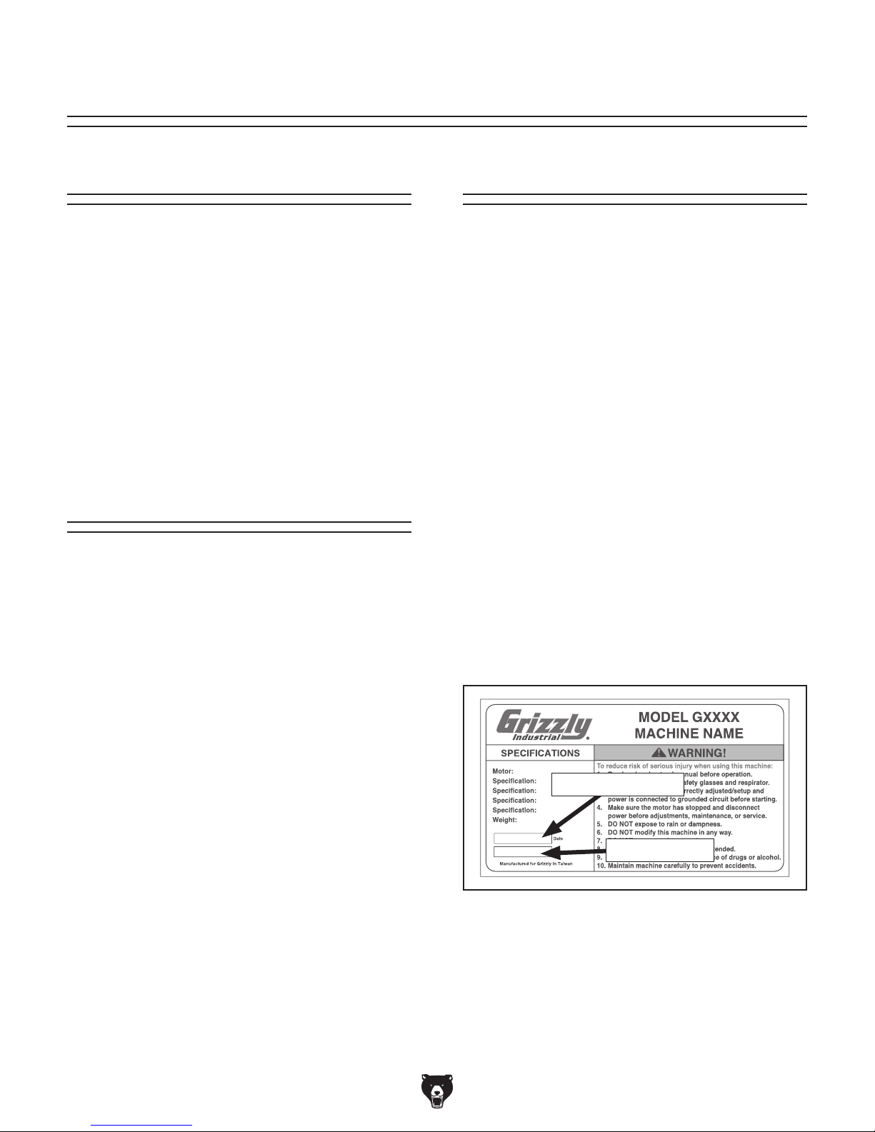
Manufacture Date
stamped
into the machine ID label (see below). This information helps us determine if updated documentation is available for your machine.
Machine Description
A lathe removes material from a rotating workpiece
secured to the spindle with a chuck or faceplate. A
cutting tool is mounted in the tool post or tailstock
and moved against the spinning workpiece to
perform the cut.
This micro lathe is great for jewelers, model makers, or hobbyists who want to turn small parts,
but don't have the need (or space) for a full-sized
lathe. It features a 4" swing, 6" distance between
centers, variable-speed spindle, and a 3-jaw
chuck.
Contact Info
Manual Accuracy
made every effort to be exact with the
our policy of continuous improvement
sometimes the machine
.
,
e post current
manual updates for free on our website at
.
and Serial Number
Grizzly Technical Support
1203 Lycoming Mall Circle
Muncy, PA 17756
Phone: (570) 546-9663
Email: techsupport@grizzly.com
Grizzly Documentation Manager
Bellingham, WA 98227-2069
Email: manuals@grizzly.com
P.O. Box 2069
Manufacture Date
Serial Number
-2-
Model G0745 (Mfg. Since 11/13)

Identification
C F
D
B
A
P
E
O
G
H
N
I
J
K
L
M
Figure 1. G0745 identification.
A. Headstock End Cover
B. Emergency Stop Button
C. Spindle Speed Dial
D. Fault Indicator Light
E. Power Light
F. Chuck Guard
G. 3-Jaw Chuck
H. Tool Post
Serious personal injury could occur if
you connect the machine to power before
completing the setup process. DO NOT
connect power until instructed to do so
later in this manual.
I. Cross Slide
J. Center
K. Tailstock
L. Backsplash
M. Carriage Handwheel
N. Carriage
O. Cross Slide Handwheel
P. Rubber Foot
Untrained lathe operators have an
increased risk of becoming seriously
injured. Do not operate this machine until
you have understood this entire manual
and received proper training.
Model G0745 (Mfg. Since 11/13)
-3-
Controls &
To reduce your risk of
serious injury, read this
entire manual BEFORE
Components
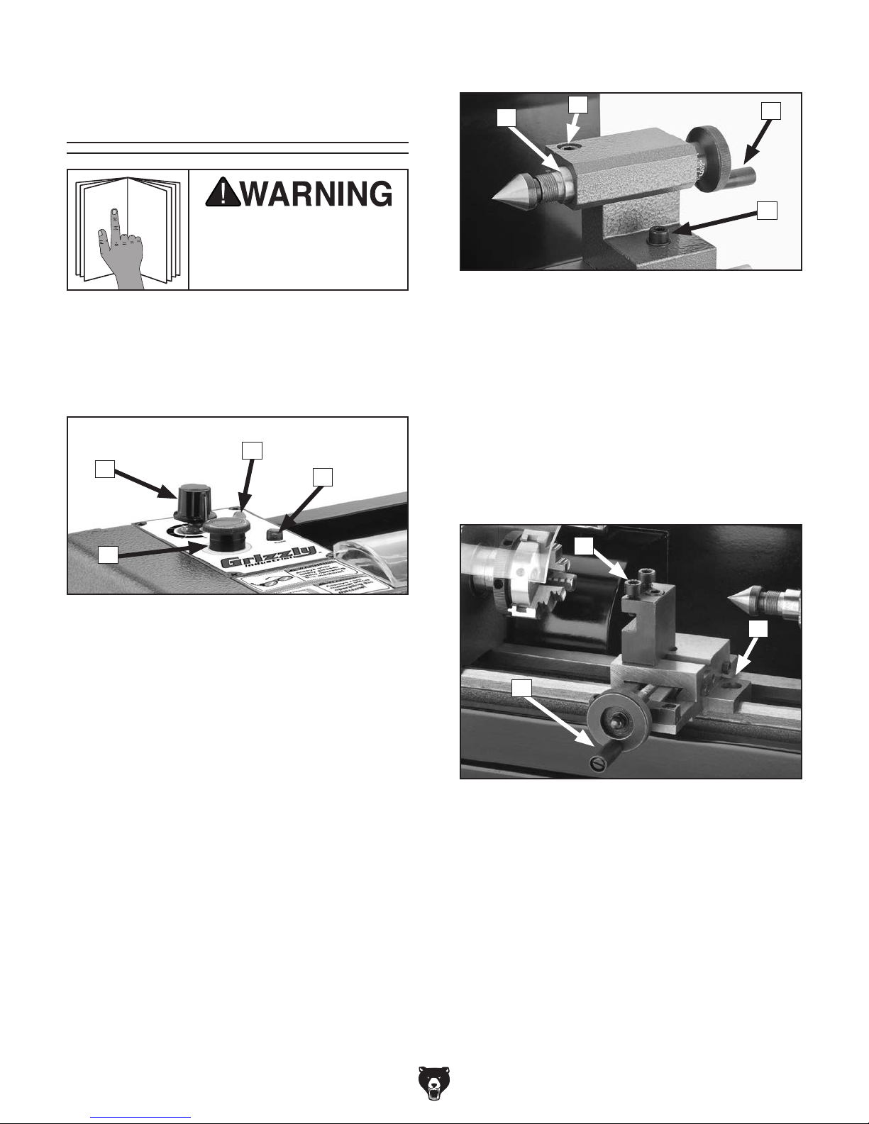
Tailstock
E
F
G
H
using machine.
Refer to Figures 2–6 and the following descriptions to become familiar with the basic controls of
this lathe.
Electrical Controls
B
A
D
Figure 2. Electrical controls.
A. Spindle Speed Dial: Starts and stops spin-
dle rotation, and controls spindle speed when
rotated. Rotate fully counterclockwise to turn
OFF. Rotate fully clockwise to maximize
spindle speed.
C
Figure 3. Tailstock controls.
E. Tailstock Quill: Holds centers or tooling.
F. Quill Lock Screw: Secures the quill.
G. Tailstock Quill Handwheel: Moves the
mounted center toward or away from the
workpiece.
H. Tailstock Lock: Secures tailstock to bedway.
Carriage
I
J
K
B. Fault Indicator Light: Illuminates if chuck
guard is opened during spindle rotation.
Close guard and turn spindle speed dial OFF
to reset indicator.
C. Power Light: Illuminates when machine is
connected to power.
D. Emergency Stop Button: Cuts power to
motor and electrical controls when pressed.
Remains depressed until reset by twisting
clockwise.
-4-
Figure 4. Carriage controls.
I. Tool Post: Holds tooling.
J. Carriage Lock Screw: Secures the carriage
for greater rigidity when it should not move.
K. Cross Slide Handwheel: Moves the tool
toward and away from the workpiece.
Model G0745 (Mfg. Since 11/13)

L
V-Belt & Pulleys
M
N
Figure 5. Carriage handwheel location.
L. Carriage Handwheel: Moves carriage along
bedway.
M. Pulleys: Transfer power from motor to the
N. V-Belt: Transfers power from the motor pul-
Figure 6. G0745 V-belt and pulleys.
spindle with the V-belt.
ley to the spindle pulley.
Glossary of Terms
The following is a list of common definitions, terms and phrases used throughout this manual as they relate
to this lathe and metalworking in general. Become familiar with these terms for assembling, adjusting or
operating this machine. Your safety is VERY important to us at Grizzly!
Arbor: A machine shaft that supports a cutting
tool.
Backlash: The amount of free-play felt
while changing rotation directions with the
handwheels.
Cutting Speed: The distance a point on a cutter
moves in one minute, expressed in meters or
feet per minute.
Facing: In lathe work, cutting across the end of
a workpiece, usually to machine a flat surface.
Feed: The movement of a cutting tool into a
workpiece.
Gib: A tapered wedge located along a sliding
member to take up wear or to ensure a proper
fit.
Model G0745 (Mfg. Since 11/13)
-5-

Machine Data Sheet
MACHINE DATA
SHEET
Customer Service #: (570) 546-9663 · To Order Call: (800) 523-4777 · Fax #: (800) 438-5901
MODEL G0745 4" X 6" MICRO METAL LATHE
Product Dimensions:
Weight................................................................................................................................................................ 31 lbs.
Width (side-to-side) x Depth (front-to-back) x Height........................................................ 16-1/4 x 11-1/2 x 11-1/2 in.
Footprint (Length x Width)....................................................................................................................... 14 x 5-1/2 in.
Shipping Dimensions:
Type..................................................................................................................................................... Cardboard Box
Content........................................................................................................................................................... Machine
Weight................................................................................................................................................................ 36 lbs.
Length x Width x Height......................................................................................................................... 21 x 9 x 15 in.
Electrical:
Power Requirement........................................................................................................... 110V, Single-Phase, 60 Hz
Prewired Voltage.................................................................................................................................................. 110V
Full-Load Current Rating....................................................................................................................................... 1.8A
Minimum Circuit Size.............................................................................................................................................. 15A
Connection Type....................................................................................................................................... Cord & Plug
Power Cord Included.............................................................................................................................................. Yes
Power Cord Length................................................................................................................................................. 5 ft.
Power Cord Gauge......................................................................................................................................... 18 AWG
Plug Included.......................................................................................................................................................... Yes
Included Plug Type................................................................................................................................................ 5-15
Switch Type.................................................................................................................................. Variable Speed Dial
Motors:
Main
Type..................................................................................................................................................... Universal
Horsepower................................................................................................................................ 150W (1/5 HP)
Phase............................................................................................................................................ Single-Phase
Amps........................................................................................................................................................... 1.8A
Speed.......................................................................................................................................... 0 – 4000 RPM
Power Transfer ............................................................................................................................... V-Belt Drive
Bearings..................................................................................................... Shielded & Permanently Lubricated
Main Specifications:
Operation Info
Swing Over Bed...................................................................................................................................... 4.25 in.
Distance Between Centers.......................................................................................................................... 6 in.
Swing Over Cross Slide............................................................................................................................... 2 in.
Swing Over Saddle................................................................................................................................ 2-3/4 in.
Maximum Tool Bit Size........................................................................................................................... 5/16 in.
Carriage Travel...................................................................................................................................... 7-1/8 in.
Cross Slide Travel................................................................................................................................. 1-1/2 in.
-6-
Model G0745 (Mfg. Since 11/13)

Headstock Info
Spindle Bore........................................................................................................................................... 0.39 in.
Spindle Threads.................................................................................................................................... M14-1.0
Number of Spindle Speeds................................................................................................................... Variable
Spindle Speeds....................................................................................................................... 100 – 3800 RPM
Spindle Bearings...................................................................... Sealed & Permanently Lubricated Ball Bearing
Tailstock Info
Tailstock Quill Travel................................................................................................................................ 7/8 in.
Tailstock Barrel Diameter....................................................................................................................... 0.39 in.
Dimensions
Bed Width............................................................................................................................................ 2-5/16 in.
Leadscrew Diameter............................................................................................................................... 5/16 in.
Leadscrew TPI......................................................................................................................................... 18 TPI
Leadscrew Length..................................................................................................................................... 12 in.
Construction
Headstock............................................................................................................................................ Cast Iron
Bed.................................................................................................. Hardened and Precision-Ground Cast Iron
Body..................................................................................................................................................... Cast Iron
Stand............................................................................................................................................. Formed Steel
Paint......................................................................................................................................................... Epoxy
Other Specifications:
Country Of Origin ............................................................................................................................................... China
Warranty ........................................................................................................................................................... 1 Year
Serial Number Location ........................................................................................................... ID Label on Headstock
ISO 9001 Factory .................................................................................................................................................. Yes
CSA Certified .......................................................................................................................................................... No
Features:
Chuck Safety Shield
Variable Spindle Speeds of 100 – 3800 RPM
Small Footprint
Non-Marring Rubber Feet
Accessories Included:
2" 3-Jaw Chuck
Tailstock Dead Center
Cross-Slide Mounted Tool Holder
Open-End Wrench 5.5 x 7mm
Phillips Screwdriver #2
Hex Wrenches 3, 4, and 5mm
Model G0745 (Mfg. Since 11/13)
-7-
SECTION 1: SAFETY
For Your Own Safety, Read Instruction
Manual Before Operating This Machine
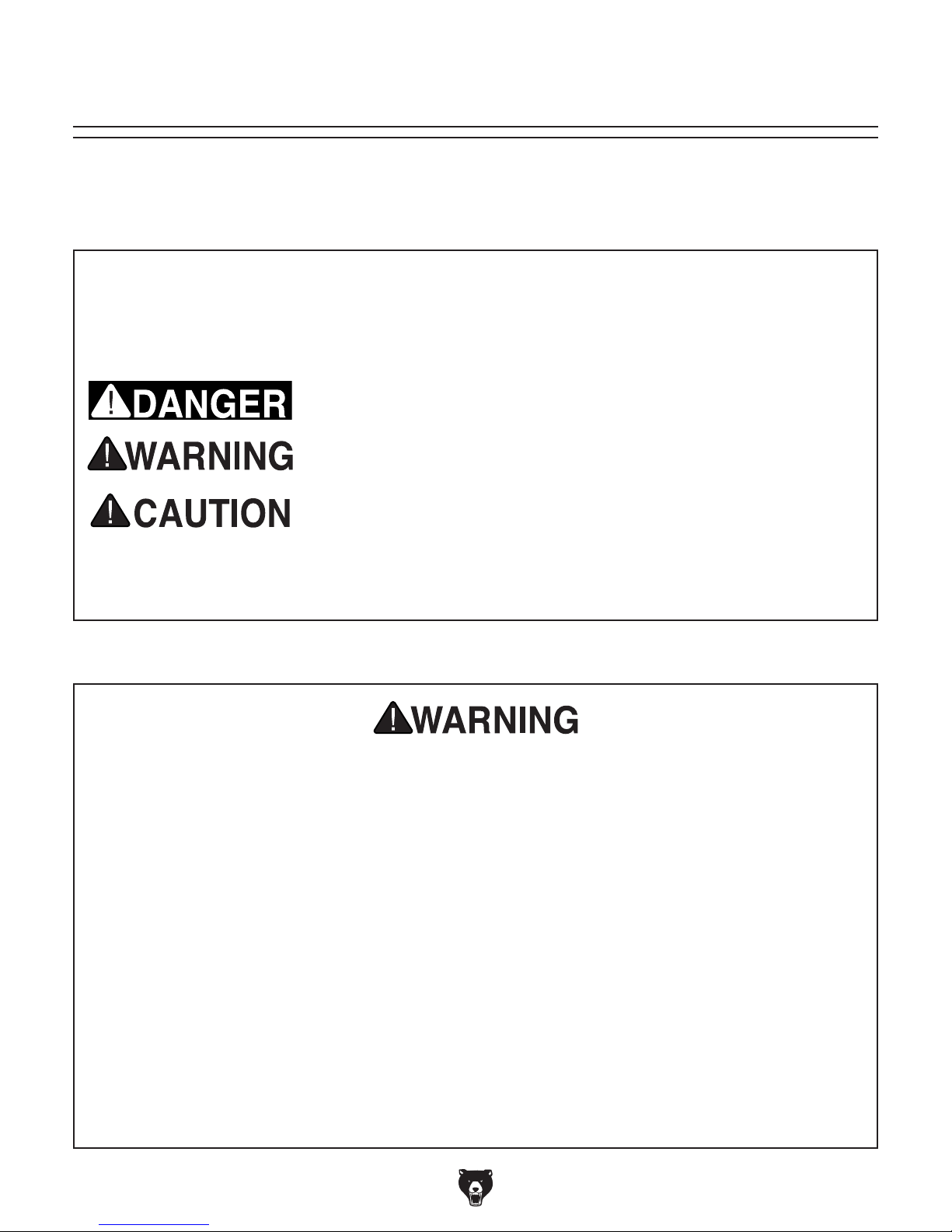
The purpose of safety symbols is to attract your attention to possible hazardous conditions.
This manual uses a series of symbols and signal words intended to convey the level of importance of the safety messages. The progression of symbols is described below. Remember that
safety messages by themselves do not eliminate danger and are not a substitute for proper
accident prevention measures. Always use common sense and good judgment.
Indicates an imminently hazardous situation which, if not avoided,
WILL result in death or serious injury.
Indicates a potentially hazardous situation which, if not avoided,
COULD result in death or serious injury.
Indicates a potentially hazardous situation which, if not avoided,
MAY result in minor or moderate injury. It may also be used to alert
against unsafe practices.
This symbol is used to alert the user to useful information about
NOTICE
proper operation of the machine.
Safety Instructions for Machinery
OWNER’S MANUAL. Read and understand this
owner’s manual BEFORE using machine.
TRAINED OPERATORS ONLY. Untrained operators have a higher risk of being hurt or killed.
Only allow trained/supervised people to use this
machine. When machine is not being used, disconnect power, remove switch keys, or lock-out
machine to prevent unauthorized use—especially
around children. Make workshop kid proof!
DANGEROUS ENVIRONMENTS. Do not use
machinery in areas that are wet, cluttered, or have
poor lighting. Operating machinery in these areas
greatly increases the risk of accidents and injury.
MENTAL ALERTNESS REQUIRED. Full mental
alertness is required for safe operation of machinery. Never operate under the influence of drugs or
alcohol, when tired, or when distracted.
ELECTRICAL EQUIPMENT INJURY RISKS. You
can be shocked, burned, or killed by touching live
electrical components or improperly grounded
machinery. To reduce this risk, only allow qualified
service personnel to do electrical installation or
repair work, and always disconnect power before
accessing or exposing electrical equipment.
DISCONNECT POWER FIRST.
nect machine from power supply BEFORE making
adjustments, changing tooling, or servicing machine.
This prevents an injury risk from unintended startup
or contact with live electrical components.
EYE PROTECTION. Always wear ANSI-approved
safety glasses or a face shield when operating or
observing machinery to reduce the risk of eye
injury or blindness from flying particles. Everyday
eyeglasses are NOT approved safety glasses.
Always discon-
-8-
Model G0745 (Mfg. Since 11/13)

WEARING PROPER APPAREL. Do not wear
clothing, apparel or jewelry that can become
entangled in moving parts. Always tie back or
cover long hair. Wear non-slip footwear to avoid
accidental slips, which could cause loss of workpiece control.
HAZARDOUS DUST. Dust created while using
machinery may cause cancer, birth defects, or
long-term respiratory damage. Be aware of dust
hazards associated with each workpiece material,
and always wear a NIOSH-approved respirator to
reduce your risk.
HEARING PROTECTION. Always wear hearing protection when operating or observing loud
machinery. Extended exposure to this noise
without hearing protection can cause permanent
hearing loss.
REMOVE ADJUSTING TOOLS. Tools left on
machinery can become dangerous projectiles
upon startup. Never leave chuck keys, wrenches,
or any other tools on machine. Always verify
removal before starting!
USE CORRECT TOOL FOR THE JOB. Only use
this tool for its intended purpose—do not force
it or an attachment to do a job for which it was
not designed. Never make unapproved modifications—modifying tool or using it differently than
intended may result in malfunction or mechanical
failure that can lead to personal injury or death!
AWKWARD POSITIONS. Keep proper footing
and balance at all times when operating machine.
Do not overreach! Avoid awkward hand positions
that make workpiece control difficult or increase
the risk of accidental injury.
CHILDREN & BYSTANDERS. Keep children and
bystanders at a safe distance from the work area.
Stop using machine if they become a distraction.
FORCING MACHINERY. Do not force machine.
It will do the job safer and better at the rate for
which it was designed.
NEVER STAND ON MACHINE. Serious injury
may occur if machine is tipped or if the cutting
tool is unintentionally contacted.
STABLE MACHINE. Unexpected movement during operation greatly increases risk of injury or
loss of control. Before starting, verify machine is
stable and mobile base (if used) is locked.
USE RECOMMENDED ACCESSORIES. Consult
this owner’s manual or the manufacturer for recommended accessories. Using improper accessories will increase the risk of serious injury.
UNATTENDED OPERATION. To reduce the
risk of accidental injury, turn machine OFF and
ensure all moving parts completely stop before
walking away. Never leave machine running
while unattended.
MAINTAIN WITH CARE. Follow all maintenance
instructions and lubrication schedules to keep
machine in good working condition. A machine
that is improperly maintained could malfunction,
leading to serious personal injury or death.
CHECK DAMAGED PARTS. Regularly inspect
machine for any condition that may affect safe
operation. Immediately repair or replace damaged
or mis-adjusted parts before operating machine.
MAINTAIN POWER CORDS. When disconnecting cord-connected machines from power, grab
and pull the plug—NOT the cord. Pulling the cord
may damage the wires inside. Do not handle
cord/plug with wet hands. Avoid cord damage by
keeping it away from heated surfaces, high traffic
areas, harsh chemicals, and wet/damp locations.
GUARDS & COVERS. Guards and covers reduce
accidental contact with moving parts or flying
debris. Make sure they are properly installed,
undamaged, and working correctly.
Model G0745 (Mfg. Since 11/13)
EXPERIENCING DIFFICULTIES. If at any time
you experience difficulties performing the intended operation, stop using the machine! Contact our
Technical Support at (570) 546-9663.
-9-

Additional Safety for Metal Lathes
Serious injury or death can occur from getting entangled in, crushed between, or struck by
rotating parts on a lathe! Unsecured tools or workpieces attached to rotating objects can also
strike nearby operators with deadly force. To minimize the risk of getting hurt or killed, anyone
operating this machine MUST completely heed the hazards and warnings below.
CLOTHING, JEWELRY & LONG HAIR. Tie back
long hair, remove jewelry, and do not wear loose
clothing or gloves. These can easily get caught on
rotating parts and pull you into lathe.
ROTATIN G PAR TS. Always keep hands and body
at a safe distance from rotating parts—especially
those with projecting surfaces. Never hold anything against rotating workpiece, such as emery
cloth, that can pull you into lathe.
GUARDING. Guards and covers protect against
injuries from entanglement or flying objects. Always
ensure they are properly installed and positioned
before startup.
ADJUSTMENT TOOLS. Remove all chuck keys,
wrenches, and adjustment tools before turning
lathe ON. A chuck key or other tool left on the lathe
can become a deadly projectile when spindle is
started.
SAFE CLEARANCES. Before starting spindle,
verify workpiece has adequate clearance by handrotating it through its entire range of motion.
NEW SETUPS. Test each new setup by standing
to the side of the lathe and starting spindle rotation
at the lowest speed until workpiece reaches full
speed and you can verify safe rotation.
SPINDLE SPEEDS. Using spindle speeds that are
too fast for the workpiece or clamping equipment
can cause rotating parts to come loose and strike
nearby people with deadly force. Always use slow
spindle speeds with large or non-concentric workpieces. Never exceed rate RPM of the chuck.
LONG STOCK SAFETY. Long stock can whip
violently if not properly supported. Always support
any stock that extends from the chuck/headstock
more than three times its own diameter.
CLEARING CHIPS. Metal chips can be razor
sharp. Avoid clearing them by hand or with a rag.
Use a brush or vacuum instead.
SECURE WORKPIECE. An improperly secured
workpiece can fly off spindle with deadly force.
Make sure workpiece is properly secured before
starting the lathe.
STOPPING SPINDLE. Always allow spindle to
completely stop on its own. Never put hands or
another object on a spinning workpiece to make it
stop faster.
CRASHING. A serious explosion of metal parts
can occur if cutting tool or other lathe component
hits rotating chuck or a projecting part of workpiece. Resulting metal fragments can strike nearby
people and lathe will be seriously damaged. To
reduce risk of crashing, NEVER leave lathe unattended, and CHECK all clearances before starting
lathe.
SANDING/POLISHING. To reduce risk of entanglement, never wrap emery cloth around rotating
workpiece. Instead, use emery cloth with the aid
of a tool or backing board.
MEASURING WORKPIECE. To reduce risk of
entanglement, never measure a spinning workpiece.
-10 -
Model G0745 (Mfg. Since 11/13)
SECTION 2: POWER SUPPLY
Before installing the machine, consider the availability and proximity of the required power supply
circuit. If an existing circuit does not meet the
requirements for this machine, a new circuit must
be installed. To minimize the risk of electrocution,
fire, or equipment damage, installation work and
electrical wiring must be done by an electrician or
qualified service personnel in accordance with all
applicable codes and standards.
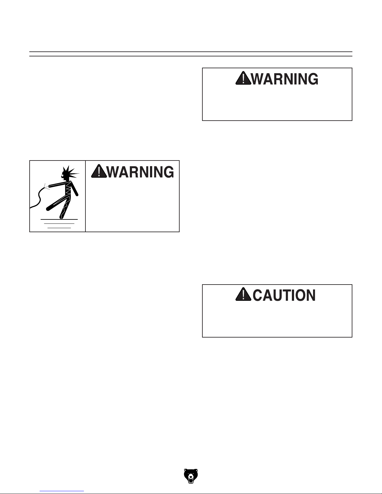
Electrocution, fire, or
equipment damage may
occur if machine is not
correctly grounded and
connected to the power
The full-load current rating is the amperage a
machine draws at 100% of the rated output power.
On machines with multiple motors, this is the
amperage drawn by the largest motor or sum of all
motors and electrical devices that might operate
at one time during normal operations.
The full-load current is not the maximum amount
of amps that the machine will draw. If the machine
is overloaded, it will draw additional amps beyond
the full-load rating.
If the machine is overloaded for a sufficient length
of time, damage, overheating, or fire may result—
especially if connected to an undersized circuit.
To reduce the risk of these hazards, avoid overloading the machine during operation and make
sure it is connected to a power supply circuit that
meets the specified circuit requirements.
For your own safety and protection of
Note: The circuit requirements listed in this man-
ual apply to a dedicated circuit—where only one
machine will be running at a time. If this machine
will be connected to a shared circuit where multiple machines will be running at the same time,
consult a qualified electrician to ensure that the
circuit is properly sized for safe operation.
A power supply circuit includes all electrical
equipment between the breaker box or fuse panel
in the building and the machine. The power supply circuit used for this machine must be sized to
safely handle the full-load current drawn from the
machine for an extended period of time. (If this
machine is connected to a circuit protected by
fuses, use a time delay fuse marked D.)
This machine is prewired to operate on a power
supply circuit that has a verified ground and meets
the following requirements:
Availability
Serious injury could occur if you connect
the machine to power before completing the
setup process. DO NOT connect to power
until instructed later in this manual.
110V Circuit Requirements
Nominal Voltage .................... 110V, 115V, 120V
Cycle .......................................................... 60 Hz
Phase ........................................... Single-Phase
Power Supply Circuit ......................... 15 Amps
supply.
Full-Load Current Rating
Full-Load Current Rating at 110V ..... 1.8 Amps
Model G0745 (Mfg. Since 11/13)
property, consult an electrician if you are
unsure about wiring practices or electrical
codes in your area.
-11-

Improper connection of the equipment-grounding
wire can result in a risk of electric shock. The
wire with green insulation (with or without yellow
stripes) is the equipment-grounding wire. If repair
or replacement of the power cord or plug is necessary, do not connect the equipment-grounding
wire to a live (current carrying) terminal.
Check with a qualified electrician or service personnel if you do not understand these grounding
requirements, or if you are in doubt about whether
the tool is properly grounded. If you ever notice
that a cord or plug is damaged or worn, disconnect it from power, and immediately replace it with
a new one.
We do not recommend using an extension cord
with this machine.
cord, only use it if absolutely necessary and only
on a temporary basis.
Extension cords cause voltage drop, which may
damage electrical components and shorten motor
life. Voltage drop increases as the extension cord
size gets longer and the gauge size gets smaller
(higher gauge numbers indicate smaller sizes).
Any extension cord used with this machine must
contain a ground wire, match the required plug
and receptacle, and meet the following requirements:
Grounding & Plug Requirements
it will not fit the outlet, have a qualified
electrician install the proper outlet with a
This machine MUST be grounded. In the event
of certain malfunctions or breakdowns, grounding
reduces the risk of electric shock by providing a
path of least resistance for electric current.
This machine is equipped with a power cord that
has an equipment-grounding wire and a grounding plug (similar to the figure below). The plug
must only be inserted into a matching receptacle
(outlet) that is properly installed and grounded in
accordance with all local codes and ordinances.
GROUNDED
5-15 RECEPTACLE
Grounding Prong
5-15 PLUG
Extension Cords
If you must use an extension
Neutral Hot
Figure 7. Typical 5-15 plug and receptacle.
SHOCK HAZARD!
Two-prong outlets do not meet the grounding
requirements for this machine. Do not modify
or use an adapter on the plug provided—if
verified ground.
-12-
Minimum Gauge Size ...........................18 AWG
Maximum Length (Shorter is Better).......50 ft.
Model G0745 (Mfg. Since 11/13)

SECTION 3: SETUP
Your machine was carefully packaged for safe
transportation. Remove the packaging materials
from around your machine and inspect it. If you
discover any damage, please call us immediately
at (570) 546-9663
Save the containers and all packing materials for
possible inspection by the carrier or its agent.
Otherwise, filing a freight claim can be difficult.
When you are completely satisfied with the condition of your shipment, inventory the contents.
Keep children and pets away
from plastic bags or packing
materials shipped with this
Unpacking
for advice.
SUFFOCATION HAZARD!
Needed for Setup
The following are needed to complete the setup
process, but are not included with your machine.
Description Qty
• Safety Glasses ........................................... 1
• Cleaner/Degreaser (Page 15) .... As Needed
• Disposable Shop Rags ............... As Needed
• Screwdriver Flat Head #1 ........................... 1
machine. Discard immediately.
Model G0745 (Mfg. Since 11/13)
-13-
Inventory
The following is a list of items shipped with your
machine. Before beginning setup, lay these items
out and inventory them.
If any non-proprietary parts are missing (e.g. a
nut or a washer), we will gladly replace them; or
for the sake of expediency, replacements can be
obtained at your local hardware store.
NOTICE
If you cannot find an item on this list, carefully check around/inside the machine and
packaging materials. Often, these items get
lost in packaging materials while unpacking or they are pre-installed at the factory.
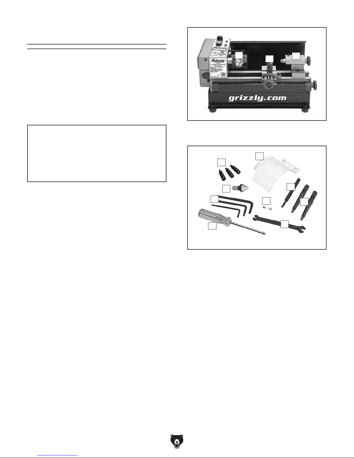
Box 1 (Figures 8–9) Qty
A. 3-Jaw Chuck 2" (Pre-installed) ................... 1
B. Tool Post (Pre-installed) ............................ 1
C. Tail stoc k (Pre-installed) .............................. 1
D. Handwheel Handles ................................... 3
E. Chuck Guard .............................................. 1
F. Spindle Key 5mm ....................................... 1
G. Chuck Keys 5mm ....................................... 2
H. Wrench 5.5 x 7mm Open-Ends .................. 1
I. Phillips Head Screwdriver #1...................... 1
J. Hex Wrenches 3, 4, 5mm .....................1 Ea.
K. Center ......................................................... 1
L. Replacement Fuse 2A ................................ 1
A
Figure 8. Lathe as shipped, with pre-installed
inventory items shown.
D
K
J
I
Figure 9. Loose inventory items.
B
E
L
C
F
G
H
-14-
Model G0745 (Mfg. Since 11/13)
 Loading...