

Page 1

MODEL G0740
14" X 40" HIGH-PRECISION
TOOLROOM LATHE
OWNER'S MANUAL
(For models manufactured since 11/12)
COPYRIGHT © DECEMBER, 2012 BY GRIZZLY INDUSTRIAL, INC.
WARNING: NO PORTION OF THIS MANUAL MAY BE REPRODUCED IN ANY SHAPE
OR FORM WITHOUT THE WRITTEN APPROVAL OF GRIZZLY INDUSTRIAL, INC.
#BL15452 PRINTED IN TAIWA N
Page 2

This manual provides critical safety instructions on the proper setup,
operation, maintenance, and service of this machine/tool. Save this
document, refer to it often, and use it to instruct other operators.
Failure to read, understand and follow the instructions in this manual
may result in fire or serious personal injury—including amputation,
electrocution, or death.
The owner of this machine/tool is solely responsible for its safe use.
This responsibility includes but is not limited to proper installation in
a safe environment, personnel training and usage authorization,
proper inspection and maintenance, manual availability and comprehension, application of safety devices, cutting/sanding/grinding tool
integrity, and the usage of personal protective equipment.
The manufacturer will not be held liable for injury or property damage
from negligence, improper training, machine modifications or misuse.
Some dust created by power sanding, sawing, grinding, drilling, and
other construction activities contains chemicals known to the State
of California to cause cancer, birth defects or other reproductive
harm. Some examples of these chemicals are:
• Lead from lead-based paints.
• Crystalline silica from bricks, cement and other masonry products.
• Arsenic and chromium from chemically-treated lumber.
Your risk from these exposures varies, depending on how often you
do this type of work. To reduce your exposure to these chemicals:
Work in a well ventilated area, and work with approved safety equipment, such as those dust masks that are specially designed to filter
out microscopic particles.
Page 3

Table of Contents
INTRODUCTION ............................................... 3
Machine Description ...................................... 3
Contact Info.................................................... 3
Manual Accuracy ........................................... 3
Identification ................................................... 4
Controls & Components ................................. 5
Two-Speed Motor Switch .................................... 5
Headstock ...........................................................5
Control Panel ...................................................... 6
Carriage .............................................................. 6
Tailstock .............................................................. 7
End Gears ........................................................... 7
Safety Foot Brake ............................................... 7
Machine Data Sheet ...................................... 8
SECTION 1: SAFETY ..................................... 11
Safety Instructions for Machinery ................ 11
Additional Safety for Metal Lathes ............... 13
Additional Chuck Safety ............................... 14
SECTION 2: POWER SUPPLY ...................... 15
Availability .........................................................15
Full-Load Current Rating .................................. 15
Circuit Requirements for 220V ..........................15
Grounding Instructions ...................................... 16
Extension Cords ................................................ 16
Correcting Phase Polarity Wiring ................. 17
SECTION 3: SETUP ....................................... 18
Preparation .................................................. 18
Unpacking .................................................... 18
Needed for Setup ......................................... 18
Inventory ...................................................... 19
Cleanup ........................................................ 20
Site Considerations ...................................... 21
Lifting & Moving ........................................... 22
Leveling & Mounting .................................... 23
Leveling ............................................................. 23
Bolting to Concrete Floors ................................24
Assembly ..................................................... 24
Lubricating Lathe ......................................... 24
Adding Coolant ............................................ 25
Power Connection........................................ 25
Test Run ...................................................... 26
Spindle Break-In .......................................... 29
Recommended Adjustments ........................ 30
SECTION 4: OPERATIONS ........................... 31
Operation Overview ..................................... 31
Chuck & Faceplate Mounting....................... 32
Installation & Removal Devices ................... 32
Chuck Installation......................................... 33
Registration Marks ............................................ 34
Chuck Removal............................................ 34
Scroll Chuck Clamping ................................ 35
Chuck Jaw Reversal .................................... 35
4-Jaw Chuck ................................................ 36
Faceplate ..................................................... 37
Tailstock ....................................................... 38
Positioning Tailstock ......................................... 38
Using Quill ......................................................... 38
Installing Tooling ............................................... 38
Removing Tooling ............................................. 39
Offsetting Tailstock ...........................................39
Aligning Tailstock to Spindle Centerline ...........40
Centers ........................................................ 42
Dead Centers .................................................... 42
Live Centers ...................................................... 42
Mounting Dead Center in Spindle ..................... 42
Removing Center from Spindle .........................43
Mounting Center in Tailstock ............................43
Removing Center from Tailstock ......................43
Mounting Workpiece Between Centers ............44
Steady Rest ................................................. 45
Follow Rest .................................................. 46
Carriage & Slide Locks ................................ 46
Compound Rest ........................................... 47
Four-Way Tool Post ..................................... 47
Installing Tool .................................................... 47
Aligning Cutting Tool with Spindle Centerline ... 48
Adjustable Feed Stop .................................. 49
Micrometer Stop........................................... 49
Manual Feed ................................................ 50
Carriage Handwheel ......................................... 50
Cross Slide Handwheel .................................... 50
Compound Rest Handwheel ............................. 50
Spindle Speed.............................................. 50
Determining Spindle Speed .............................. 50
Setting Spindle Speed ......................................51
Configuration Examples .................................... 51
Power Feed.................................................. 52
Power Feed Controls ........................................ 53
Setting Power Feed Rate ..................................54
End Gears .................................................... 55
Page 4

Standard End Gear Configuration ....................55
Alternate Configuration ..................................... 56
Threading ..................................................... 57
Headstock Threading Controls .........................57
Apron Threading Controls ................................. 58
Thread Dial .......................................................58
Thread Dial Chart ............................................. 59
Chip Drawer ................................................. 60
Coolant System............................................ 61
SECTION 5: ACCESSORIES ......................... 62
SECTION 6: MAINTENANCE ......................... 64
Schedule ...................................................... 64
Ongoing ............................................................64
Daily, Before Operations ................................... 64
Daily, After Operations ...................................... 64
Monthly .............................................................64
Semi-Annually ................................................... 64
Annually ............................................................ 64
Cleaning/Protecting ...................................... 64
Lubrication ................................................... 65
Headstock ......................................................... 65
Quick-Change Gearbox .................................... 66
Apron ................................................................67
One-Shot Oiler .................................................. 67
Longitudinal Leadscrew .................................... 68
Ball Oilers & Oil Cup ......................................... 68
End Gears ......................................................... 69
Coolant System Service .............................. 70
Hazards ............................................................. 70
Adding Coolant .................................................71
Changing Coolant ............................................. 71
Machine Storage .......................................... 72
SECTION 7: SERVICE ................................... 73
Troubleshooting ........................................... 73
Motor & Electrical .............................................. 73
Lathe Operation ................................................ 74
Backlash Adjustment ................................... 76
Compound Rest ................................................ 76
Cross Slide ........................................................ 76
Leadscrew End Play Adjustment ................. 77
Gib Adjustment ............................................ 77
Half Nut Adjustment ..................................... 79
V-Belts ......................................................... 79
Brake & Switch ............................................ 80
Leadscrew Shear Pin Replacement ............ 82
Gap Insert Removal & Installation ............... 84
Gap Removal .................................................... 84
Gap Installation ................................................. 84
SECTION 8: WIRING ...................................... 85
Wiring Safety Instructions ............................ 85
Wiring Overview ........................................... 86
Component Location Index .......................... 87
Electrical Cabinet Wiring .............................. 88
Electrical Box ............................................... 89
Spindle Motor ............................................... 90
Coolant Pump Wiring ................................... 90
2-Speed Motor Switch ................................. 91
Control Panel Wiring .................................... 92
Spindle Switches.......................................... 92
Additional Component Wiring ...................... 93
Power Connection........................................ 93
SECTION 9: PARTS ....................................... 94
Headstock Cover ......................................... 94
Headstock Controls...................................... 95
Headstock Internal Gears ............................ 97
Headstock Transfer Gears ........................... 99
Gearbox Gears .......................................... 100
Gearbox Controls ....................................... 102
Apron Front View ....................................... 104
Apron Rear View ........................................ 106
Compound Rest & Tool Post ..................... 108
Saddle Top View ........................................ 109
Saddle Bottom View .................................. 111
Bed Stop .................................................... 112
Dial Indicator .............................................. 112
Bed & Shafts .............................................. 113
End Gears .................................................. 115
Main Motor ................................................. 116
Cabinets & Panels ..................................... 118
Tailstock ..................................................... 120
Steady Rest ............................................... 122
Follow Rest ................................................ 122
Electrical Cabinet & Control Panel ............ 123
Accessories ................................................ 124
Front Machine Labels ................................ 125
Rear & Side Machine Labels ..................... 126
WARRANTY & RETURNS ........................... 129
Page 5
INTRODUCTION
We are proud to provide a high-quality owner’s
manual with your new machine!
We
instructions, specifications, drawings, and photographs
contained inside. Sometimes we make mistakes,
but
also
means that
you receive
will be slightly different than what is shown in
the manual
If you find this to be the case, and the difference
between the manual and machine leaves you
confused about a procedure
for an updated version. W
manuals
and
www.grizzly.com
Alternatively, you can call our Technical Support
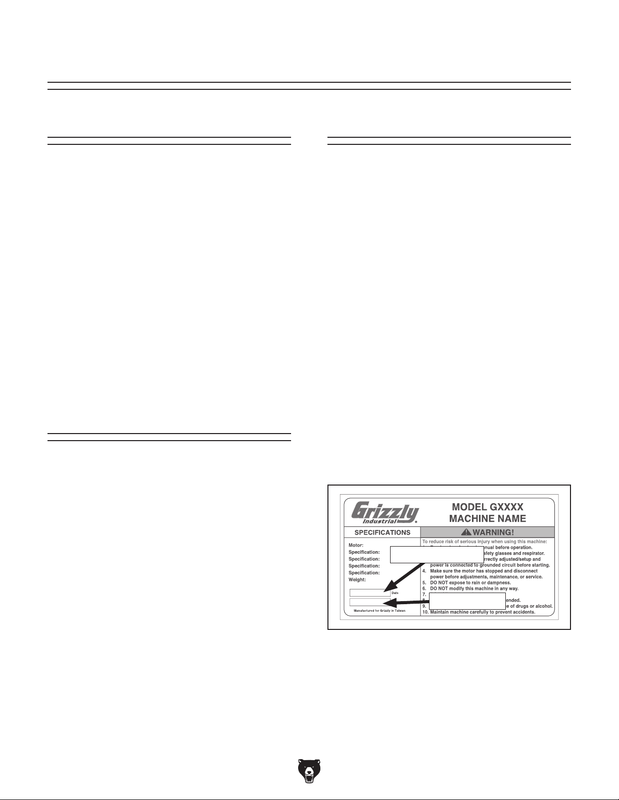
for help. Before calling, please write down the
Manufacture Date
stamped
into the machine ID label (see below). This information helps us determine if updated documentation is available for your machine.
We stand behind our machines. If you have
any questions or need help, use the information
below to contact us. Before contacting, please get
the serial number and manufacture date of your
machine. This will help us help you faster.
We want your feedback on this manual. What did
you like about it? Where could it be improved?
Please take a few minutes to give us feedback.
Machine Description
The Model G0740 metal lathe is used to remove
material from a rotating workpiece, which is held
in place on the spindle with a chuck or faceplate. The cutting tool is mounted on the carriage or tailstock and moved against the spinning
workpiece to perform the cut.
This lathe has 16 available spindle speeds and
powered feed for the carriage and cross slide. The
use of the cutting fluid system and spindle brake
is optional.
Typical cutting operations for a metal lathe include
facing, turning, parting, drilling, reaming, grooving,
knurling, and threading. There are a wide variety
of tools and workpiece holding devices available
for each of these operations.
Contact Info
Manual Accuracy
made every effort to be exact with the
our policy of continuous improvement
sometimes the machine
.
, check our website
e post current
manual updates for free on our website at
.
and Serial Number
Grizzly Technical Support
1203 Lycoming Mall Circle
Muncy, PA 17756
Phone: (570) 546-9663
Email: techsupport@grizzly.com
Grizzly Documentation Manager
P.O. Box 2069
Bellingham, WA 98227-2069
Email: manuals@grizzly.com
Manufacture Date
Serial Number
Model G0740 (Mfg. Since 11/12)
-3-
Page 6
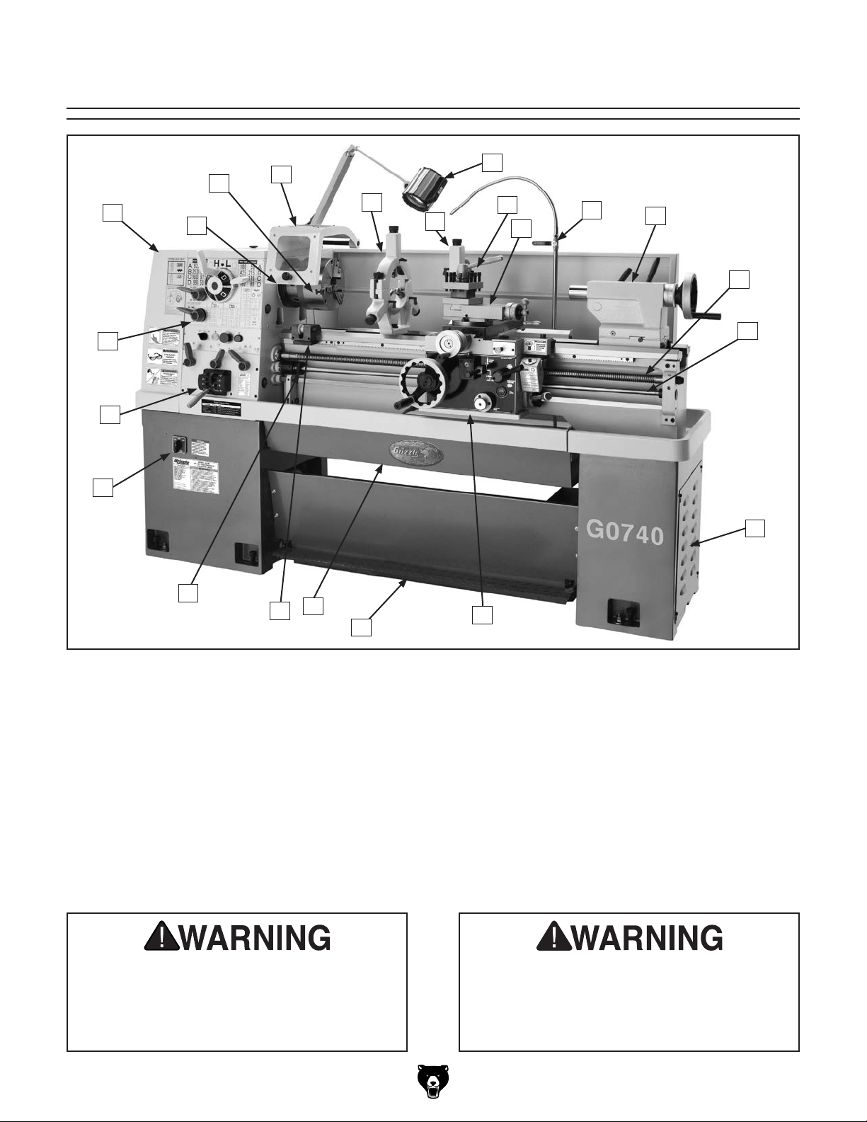
Identification
C
A
B
V
U
T
D
E
G
F
H
I
J
K
L
M
N
S
A. Headstock
B. D1-5 Camlock MT#5 Spindle
C. 3-Jaw Chuck 8"
D. Chuck Guard w/Safety Switch
E. Steady Rest
F. Halogen Work Lamp
G. Follow Rest
H. 4-Way Tool Post
I. Compound Rest
J. Coolant Nozzle & Valve
K. Tailstock (see Page 7 for details)
Serious personal injury could occur if you
connect the machine to power before completing the setup process. DO NOT connect
power until instructed to do so later in this
manual.
Q
R
P
Figure 1. Identification.
O
L. Longitudinal Leadscrew
M. Feed Rod
N. Coolant Reservoir & Pump Access
O. Carriage (see Page 6 for details)
P. Safety Foot Brake
Q. Chip Drawer
R. Micrometer Stop
S. Stop Collar
T. Two-Speed Motor Switch
U. Quick-Change Gearbox
V. Headstock Controls (see Page 5 for details)
Untrained users have an increased risk
of seriously injuring themselves with this
machine. Do not operate this machine until
you have understood this entire manual and
received proper training.
-4-
Model G0740 (Mfg. Since 11/12)
Page 7
Controls &
Components
Refer to Figures 2–6 and the following descriptions to become familiar with the basic controls of
this lathe.
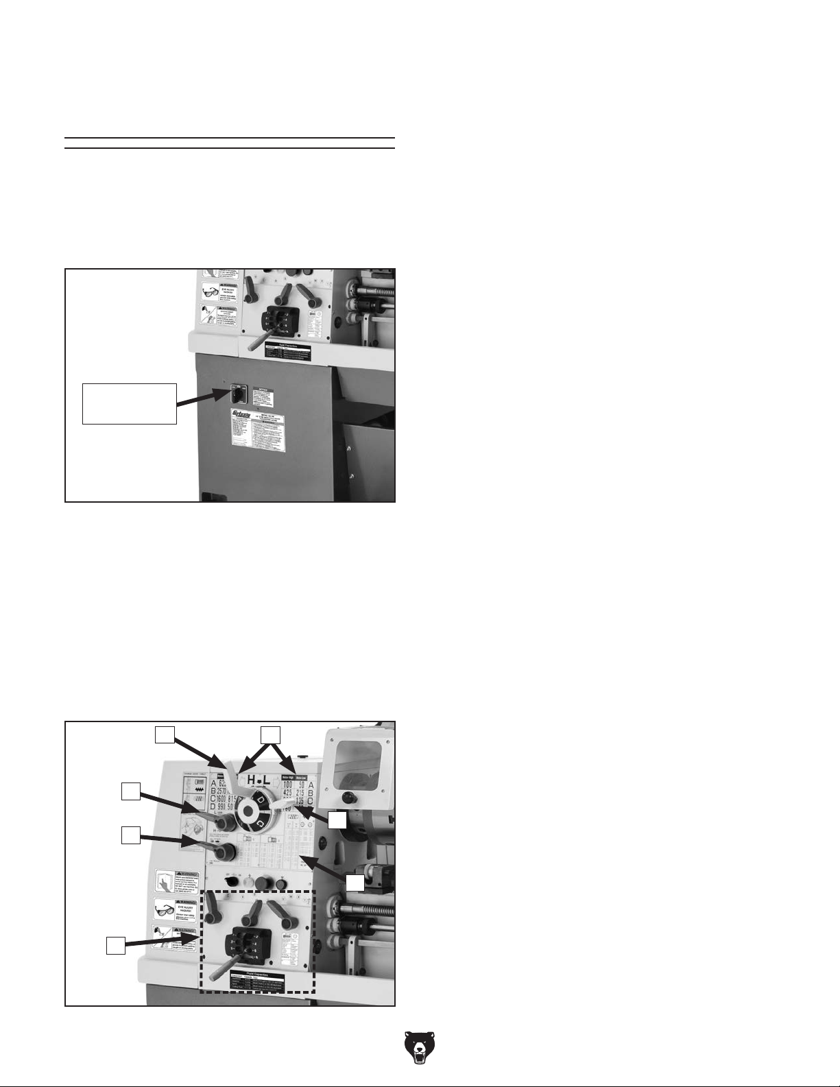
Two-Speed Motor Switch
Two-Speed
Motor Switch
A. Spindle Range Lever: Selects the speed
range on the left (high) or right (low) spindle
speed chart to be active.
B. Spindle Speed Charts: Display the arrange-
ment of the spindle range and spindle speed
levers for each of the 16 spindle speeds. The
two-speed motor switch enables the available speeds from the high or low spindle
speed chart.
C. Spindle Speed Lever: Selects one of the four
available spindle speeds within the selected
speed range.
D. Threading and Feed Charts: Displays the
necessary configuration of the gearbox levers
and end gears for different threading or feeding options.
E. Gearbox Range Lever: Shifts the quick-
change gearbox into low range, neutral, or
high range.
Figure 2. Location of the two-speed motor
switch.
The two-speed motor switch has three positions:
• Low (left position), enables speeds in the
right headstock spindle speed chart
• OFF (middle position)
• High (right position), enables speeds in the
left headstock spindle speed chart
Headstock
C
E
F
B
A
D
F. Headstock Feed Direction Lever: Controls
the direction that the leadscrew and feed rod
rotate.
G. Quick-Change Gearbox Levers: Control the
leadscrew and feed rod speed for threading
and feed operations.
G
Figure 3. Headstock controls.
Model G0740 (Mfg. Since 11/12)
-5-
Page 8
Control Panel
N. Coolant Flow Control Lever: Controls the
flow of coolant from the nozzle.
O. One-Shot Oiler: Draws oil from the apron res-
ervoir to lubricate the carriage ways through
I
J
various oil ports.
P. Carriage Lock: Secures the carriage in place
for greater rigidity when it should not move.
H
Figure 4. Control panel.
H. Coolant Pump Switch: Controls the coolant
pump motor.
I. Power Light: Illuminates when lathe controls
are receiving power.
J. STOP Button: Stops all machine functions.
Twist clockwise to reset.
K. Jog Button: Starts forward spindle rotation
as long as it is pressed.
K
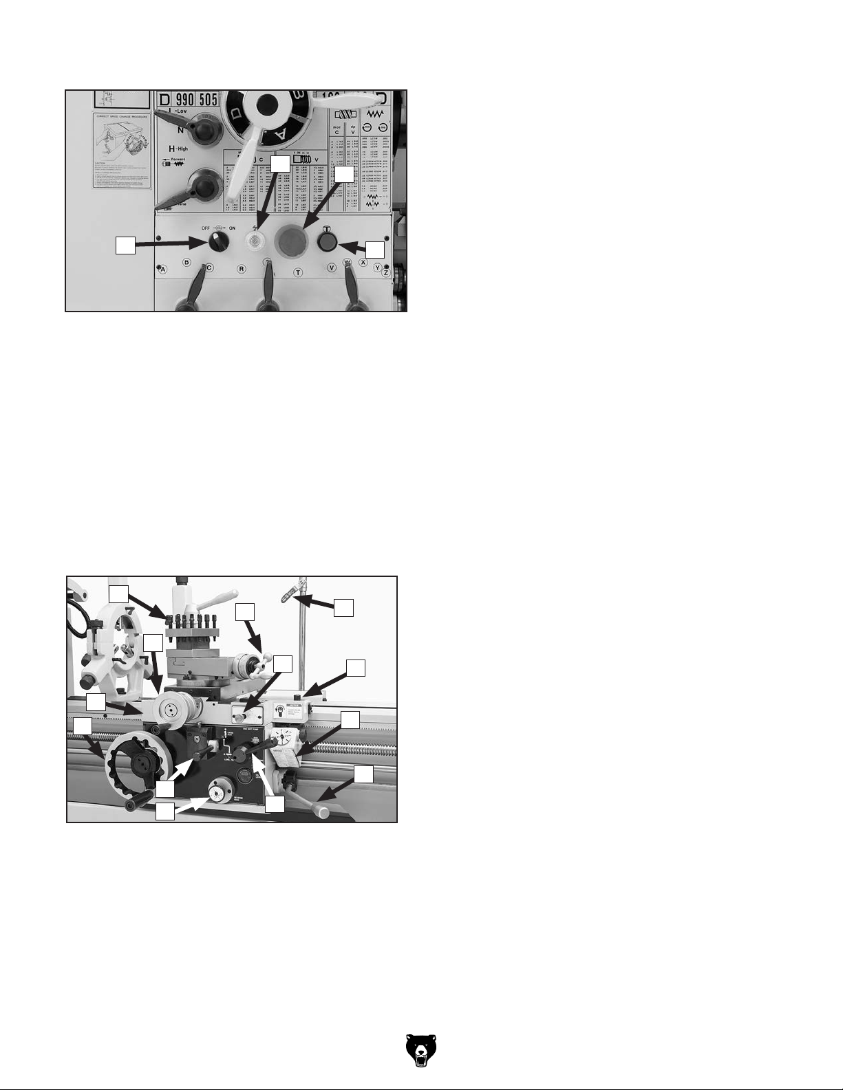
Carriage
L
M
X
O
N
P
Q . Thread Dial and Chart: Dial indicates when
to engage the half nut during threading
operations. Chart indicates on which thread
dial reading to engage the half nut for specific
inch thread pitches.
R. Spindle Lever: Starts, stops and reverses
direction of spindle rotation.
S . Half Nut Lever: Engages/disengages the
half nut for threading operations.
T. Apron Feed Direction Knob: Changes direc-
tion of the carriage or the cross slide feed
without having to stop the lathe and move the
headstock feed direction lever.
U. Feed Selection Lever: Selects the carriage
or cross slide for power feed.
V. Carriage Handwheel: Moves the carriage
along the bed.
W. Apron: Houses the carriage gearing.
W
V
V
L. 4-Way Tool Post: Mounts up to four cutting
tools at once that can be individually indexed
to the workpiece.
M. Compound Rest Handwheel: Moves the
tool toward and away from the workpiece at
the preset angle of the compound rest.
-6-
U
T
Figure 5. Carriage controls.
S
Q
R
X. Cross Slide Handwheel: Moves the cross
slide toward and away from the workpiece.
Model G0740 (Mfg. Since 11/12)
Page 9
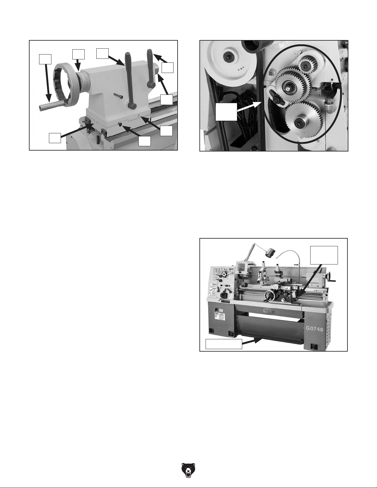
Tailstock End Gears
Y
Z
AF
Figure 6. Tailstock controls.
Y. Quill Handwheel: Moves the quill toward or
away from the spindle.
Z. Graduated Scale: Indicates quill movement
in increments of 0.001" with one full revolution equaling 0.100" of quill travel.
AA. Tailstock Lock Lever: Secures the tailstock
in position along the bedway.
AA
AB
AC
AD
AE
End
Gears
Figure 7. End gear components.
Configuring the end gears shown in Figure 7 will
control the speed of the leadscrew for threading
or the feed rod for power feed operations. The
rotational speed of these components depends
not only on the end gear configuration, but the
spindle speed as well.
Safety Foot Brake
AB. Quill Lock Lever: Secures the quill in posi-
tion.
AC. Quill: Moves toward and away from the
spindle and holds centers and tooling.
AD. Tailstock Offset Screw: Adjusts the tailstock
offset left or right from the spindle centerline
(1 of 2).
AE. Gib Adjustment Screw: Adjusts the tapered
gib to control tailstock offset accuracy
(1 of 2).
AF. Offset Scale: Indicates the relative distance
of tailstock offset from the spindle centerline.
Spindle
Lever
Foot Brake
Figure 8. Foot brake and spindle lever.
This lathe is equipped with a foot brake (see
Figure 8) to quickly stop the spindle instead of
allowing the spindle to coast to a stop on its own.
Pushing the foot brake while the spindle is ON
cuts power to the motor and stops the spindle.
After the foot brake is used, the spindle lever must
be returned to the OFF (middle) position to reset
the spindle switches before re-starting spindle
rotation.
Model G0740 (Mfg. Since 11/12)
-7-
Page 10

Machine Data Sheet
MACHINE DATA
SHEET
Customer Service #: (570) 546-9663 · To Order Call: (800) 523-4777 · Fax #: (800) 438-5901
MODEL G0740 14" X 40" 3-PHASE HIGH PRECISION
TOOLROOM METAL LATHE
Product Dimensions:
Weight............................................................................................................................................................ 2420 lbs.
Width (side-to-side) x Depth (front-to-back) x Height........................................................ 80-3/4 x 32-1/8 x 54-3/8 in.
Footprint (Length x Width)............................................................................................................... 80-3/4 x 19-1/2 in.
Shipping Dimensions:
Type................................................................................................................................................... Wood Slat Crate
Content........................................................................................................................................................... Machine
Weight............................................................................................................................................................ 2684 lbs.
Length x Width x Height....................................................................................................................... 90 x 40 x 69 in.
Electrical:
Power Requirement.................................................................................................................. 220V, 3-Phase, 60 HZ
Full-Load Current Rating..................................................................................................................................... 14.4A
Minimum Circuit Size.............................................................................................................................................. 20A
Switch...................................................................................................................... Magnetic with Thermal Protection
Switch Voltage..................................................................................................................................................... 220V
Plug Included........................................................................................................................................................... No
Recommended Plug/Outlet Type............................................................................................................. NEMA 15-20
Motors:
Main
Type........................................................................................................................................... TEFC Induction
Horsepower....................................................................................... 5 HP at 3450 RPM, 2.5 HP at 1725 RPM
Voltage....................................................................................................................................................... 220V
Phase.................................................................................................................................................... 3-Phase
Amps..................................................................................................................................................... 14A/10A
Speed....................................................................................................................................... 3450/1725 RPM
Cycle......................................................................................................................................................... 60 Hz
Number of Speeds............................................................................................................................................ 2
Power Transfer ............................................................................................................................ V-Belt & Gear
Bearings....................................................................................................... Shielded and Permanently Sealed
Coolant
Type........................................................................................................................................... TEFC Induction
Horsepower............................................................................................................................................. 1/8 HP
Voltage....................................................................................................................................................... 220V
Phase.................................................................................................................................................... 3-Phase
Amps........................................................................................................................................................... 0.4A
Cycle......................................................................................................................................................... 60 Hz
Number of Speeds............................................................................................................................................ 1
Power Transfer ............................................................................................................................... Direct Drive
Bearings....................................................................................................... Shielded and Permanently Sealed
-8-
Model G0740 (Mfg. Since 11/12)
Page 11

Main Specifications:
Paint..................................................................................................................................................... Urethane
Operation Info
Swing Over Bed.................................................................................................................................... 14.17 in.
Distance Between Centers........................................................................................................................ 40 in.
Swing Over Cross Slide.......................................................................................................................... 8.66 in.
Swing Over Saddle............................................................................................................................... 13.75 in.
Swing Over Gap................................................................................................................................... 20.94 in.
Maximum Tool Bit Size........................................................................................................................... 0.75 in.
Compound Travel........................................................................................................................................ 4 in.
Carriage Travel....................................................................................................................................... 36.5 in.
Cross Slide Travel....................................................................................................................................... 7 in.
Headstock Info
Spindle Bore......................................................................................................................................... 1.653 in.
Spindle Taper............................................................................................................................................ MT#5
Number of Spindle Speeds............................................................................................................................. 16
Spindle Speeds......................................................................................................................... 50 – 2570 RPM
Spindle Type................................................................................................................................ D1-5 Camlock
Spindle Bearings................................................................................................................ NTN Tapered Roller
Spindle Length...................................................................................................................................... 20.87 in.
Spindle Length with 3-Jaw Chuck......................................................................................................... 28.74 in.
Spindle Length with 4-Jaw Chuck......................................................................................................... 30.71 in.
Tailstock Info
Tailstock Quill Travel............................................................................................................................. 4-3/8 in.
Tailstock Taper.......................................................................................................................................... MT#3
Tailstock Barrel Diameter..................................................................................................................... 1.968 in.
Threading Info
Number of Longitudinal Feeds....................................................................................................................... 17
Range of Longitudinal Feeds................................................................................................... 0.002 – 0.067 in.
Number of Cross Feeds................................................................................................................................. 17
Range of Cross Feeds............................................................................................................. 0.001 – 0.034 in.
Number of Inch Threads................................................................................................................................. 45
Range of Inch Threads...................................................................................................................... 2 – 72 TPI
Number of Metric Threads.............................................................................................................................. 39
Range of Metric Threads................................................................................................................ 0.2 – 14 mm
Number of Modular Pitches............................................................................................................................ 18
Range of Modular Pitches.............................................................................................................. 0.3 – 3.5 MP
Number of Diametral Pitches.......................................................................................................................... 21
Range of Diametral Pitches................................................................................................................ 8 – 44 DP
Dimensions
Bed Width.................................................................................................................................................... 9 in.
Leadscrew Diameter.............................................................................................................................. 1-1/8 in.
Leadscrew TPI.................................................................................................................................................. 4
Leadscrew Length..................................................................................................................................... 59 in.
Steady Rest Capacity............................................................................................................... 5/16 – 4-5/16 in.
Follow Rest Capacity.................................................................................................................... 5/8 – 3-1/8 in.
Faceplate Size........................................................................................................................................... 10 in.
Feed Rod Diameter.................................................................................................................................. 3/4 in.
Floor to Center Height......................................................................................................................... 42-5/8 in.
Height With Leveling Jacks................................................................................................................. 54-3/8 in.
Construction
Base..................................................................................................................................................... Cast Iron
Headstock............................................................................................................................................ Cast Iron
Headstock Gears............................................................................................................ Flame Hardened Steel
Bed.................................................................................................. Induction Hardened and Ground Cast Iron
Stand.................................................................................................................................................... Cast Iron
Model G0740 (Mfg. Since 11/12)
-9-
Page 12

Other Specifications:
Country Of Origin ............................................................................................................................................. Taiwan
Warranty ........................................................................................................................................................... 1 Year
Serial Number Location ............................................................................................. ID Label on Front of Headstock
Customer Assembly & Setup Time ................................................................................................................. 2 Hours
Sound Rating ..................................................................................................................................................... 76 dB
Features:
Hardened & Precision-Ground Bed with Meehanite Castings
Halogen Work Light (24V/70W)
4-Way Tool Post
Complete Coolant System
Micrometer Carriage Stop
Threading Dial Indicator
Full Length Splash Guard
Front Removable Sliding Chip Tray
Headstock Gears Run in an Oil Bath
Jog Button and Emergency Stop
Safety Chip Guard
Completely Enclosed Universal Gearbox for Cutting Inch, Metric, Modular and Diametral Pitches
Accessories Included:
#5 to #3 Morse Taper Spindle Sleeve
10 in. 4-Jaw Independent Chuck D1-5
10 in. Faceplate D1-5
8 in. 3-Jaw Scroll Chuck D1-5
Follow Rest
Service Tools
Six Leveling Pads
Steady Rest with Roller Bearing Tips
Tool Box
Two Morse Taper #3 Dead Centers (1 Carbon Steel and 1 Carbide-Tipped)
-10 -
Model G0740 (Mfg. Since 11/12)
Page 13

SECTION 1: SAFETY
For Your Own Safety, Read Instruction
Manual Before Operating This Machine
The purpose of safety symbols is to attract your attention to possible hazardous conditions.
This manual uses a series of symbols and signal words intended to convey the level of importance of the safety messages. The progression of symbols is described below. Remember that
safety messages by themselves do not eliminate danger and are not a substitute for proper
accident prevention measures. Always use common sense and good judgment.
Indicates an imminently hazardous situation which, if not avoided,
WILL result in death or serious injury.
Indicates a potentially hazardous situation which, if not avoided,
COULD result in death or serious injury.
Indicates a potentially hazardous situation which, if not avoided,
MAY result in minor or moderate injury. It may also be used to alert
against unsafe practices.
This symbol is used to alert the user to useful information about
NOTICE
proper operation of the machine.
Safety Instructions for Machinery
OWNER’S MANUAL. Read and understand this
owner’s manual BEFORE using machine.
TRAINED OPERATORS ONLY. Untrained operators have a higher risk of being hurt or killed.
Only allow trained/supervised people to use this
machine. When machine is not being used, disconnect power, remove switch keys, or lock-out
machine to prevent unauthorized use—especially
around children. Make workshop kid proof!
DANGEROUS ENVIRONMENTS. Do not use
machinery in areas that are wet, cluttered, or have
poor lighting. Operating machinery in these areas
greatly increases the risk of accidents and injury.
MENTAL ALERTNESS REQUIRED. Full mental
alertness is required for safe operation of machinery. Never operate under the influence of drugs or
alcohol, when tired, or when distracted.
ELECTRICAL EQUIPMENT INJURY RISKS. You
can be shocked, burned, or killed by touching live
electrical components or improperly grounded
machinery. To reduce this risk, only allow qualified
service personnel to do electrical installation or
repair work, and always disconnect power before
accessing or exposing electrical equipment.
DISCONNECT POWER FIRST.
nect machine from power supply BEFORE making
adjustments, changing tooling, or servicing machine.
This prevents an injury risk from unintended startup
or contact with live electrical components.
EYE PROTECTION. Always wear ANSI-approved
safety glasses or a face shield when operating or
observing machinery to reduce the risk of eye
injury or blindness from flying particles. Everyday
eyeglasses are not approved safety glasses.
Always discon-
Model G0740 (Mfg. Since 11/12)
-11-
Page 14

WEARING PROPER APPAREL. Do not wear
clothing, apparel or jewelry that can become
entangled in moving parts. Always tie back or
cover long hair. Wear non-slip footwear to avoid
accidental slips, which could cause loss of workpiece control.
HAZARDOUS DUST. Dust created while using
machinery may cause cancer, birth defects, or
long-term respiratory damage. Be aware of dust
hazards associated with each workpiece material,
and always wear a NIOSH-approved respirator to
reduce your risk.
HEARING PROTECTION. Always wear hearing protection when operating or observing loud
machinery. Extended exposure to this noise
without hearing protection can cause permanent
hearing loss.
REMOVE ADJUSTING TOOLS. Tools left on
machinery can become dangerous projectiles
upon startup. Never leave chuck keys, wrenches,
or any other tools on machine. Always verify
removal before starting!
INTENDED USAGE. Only use machine for its
intended purpose and never make modifications
not approved by Grizzly. Modifying machine or
using it differently than intended may result in
malfunction or mechanical failure that can lead to
serious personal injury or death!
AWKWARD POSITIONS. Keep proper footing
and balance at all times when operating machine.
Do not overreach! Avoid awkward hand positions
that make workpiece control difficult or increase
the risk of accidental injury.
CHILDREN & BYSTANDERS. Keep children and
bystanders at a safe distance from the work area.
Stop using machine if they become a distraction.
FORCING MACHINERY. Do not force machine.
It will do the job safer and better at the rate for
which it was designed.
NEVER STAND ON MACHINE. Serious injury
may occur if machine is tipped or if the cutting
tool is unintentionally contacted.
STABLE MACHINE. Unexpected movement during operation greatly increases risk of injury or
loss of control. Before starting, verify machine is
stable and mobile base (if used) is locked.
USE RECOMMENDED ACCESSORIES. Consult
this owner’s manual or the manufacturer for recommended accessories. Using improper accessories will increase the risk of serious injury.
UNATTENDED OPERATION. To reduce the
risk of accidental injury, turn machine OFF and
ensure all moving parts completely stop before
walking away. Never leave machine running
while unattended.
MAINTAIN WITH CARE. Follow all maintenance
instructions and lubrication schedules to keep
machine in good working condition. A machine
that is improperly maintained could malfunction,
leading to serious personal injury or death.
CHECK DAMAGED PARTS. Regularly inspect
machine for any condition that may affect safe
operation. Immediately repair or replace damaged
or mis-adjusted parts before operating machine.
MAINTAIN POWER CORDS. When disconnecting cord-connected machines from power, grab
and pull the plug—NOT the cord. Pulling the cord
may damage the wires inside. Do not handle
cord/plug with wet hands. Avoid cord damage by
keeping it away from heated surfaces, high traffic
areas, harsh chemicals, and wet/damp locations.
GUARDS & COVERS. Guards and covers reduce
accidental contact with moving parts or flying
debris. Make sure they are properly installed,
undamaged, and working correctly.
-12-
EXPERIENCING DIFFICULTIES. If at any time
you experience difficulties performing the intended operation, stop using the machine! Contact our
Technical Support at (570) 546-9663.
Model G0740 (Mfg. Since 11/12)
Page 15

Additional Safety for Metal Lathes
Never attempt to slow or stop the lathe spindle with
SPEED RATES. Operating the lathe at the wrong
speed can cause nearby parts to break or the
workpiece to come loose, which will result in dangerous projectiles that could cause severe impact
injuries. Large or non-concentric workpieces must
be turned at slow speeds. Always use the appropriate feed and speed rates.
CHUCK KEY SAFETY. A chuck key left in the
chuck can become a deadly projectile when the
spindle is started. Always remove the chuck key
after using it. Develop a habit of not taking your
hand off of a chuck key unless it is away from the
machine.
SAFE CLEARANCES. Workpieces that crash
into other components on the lathe may throw
dangerous projectiles in all directions, leading to
impact injury and damaged equipment. Before
starting the spindle, make sure the workpiece has
adequate clearance by hand-rotating it through its
entire range of motion. Also, check the tool and
tool post clearance, chuck clearance, and saddle
clearance.
LONG STOCK SAFETY. Long stock can whip
violently if not properly supported, causing serious
impact injury and damage to the lathe. Reduce this
risk by supporting any stock that extends from the
chuck/headstock more than three times its own
diameter. Always turn long stock at slow speeds.
SECURING WORKPIECE. An improperly secured
workpiece can fly off the lathe spindle with deadly
force, which can result in a severe impact injury.
Make sure the workpiece is properly secured in the
chuck or faceplate before starting the lathe.
CHUCKS. Chucks are very heavy and difficult to
grasp, which can lead to crushed fingers or hands
if mishandled. Get assistance when handling
chucks to reduce this risk. Protect your hands and
the precision-ground ways by using a chuck cradle
or piece of plywood over the ways of the lathe
when servicing chucks. Use lifting devices when
necessary.
CLEARING CHIPS. Metal chips can easily cut
bare skin—even through a piece of cloth. Avoid
clearing chips by hand or with a rag. Use a brush
or vacuum to clear metal chips.
STOPPING SPINDLE BY HAND. Stopping the
spindle by putting your hand on the workpiece
or chuck creates an extreme risk of entanglement, impact, crushing, friction, or cutting hazards.
your hand. Allow the spindle to come to a stop on
its own or use the brake.
CRASHES. Aggressively driving the cutting tool or
other lathe components into the chuck may cause
an explosion of metal fragments, which can result
in severe impact injuries and major damage to
the lathe. Reduce this risk by releasing automatic
feeds after use, not leaving lathe unattended, and
checking clearances before starting the lathe.
Make sure no part of the tool, tool holder, compound rest, cross slide, or carriage will contact the
chuck during operation.
COOLANT SAFETY. Coolant is a very poisonous biohazard that can cause personal injury from
skin contact alone. Incorrectly positioned coolant
nozzles can splash on the operator or the floor,
resulting in an exposure or slipping hazard. To
decrease your risk, change coolant regularly and
position the nozzle where it will not splash or end
up on the floor.
TOOL SELECTION. Cutting with an incorrect or
dull tool increases the risk of accidental injury due
to the extra force required for the operation, which
increases the risk of breaking or dislodging components that can cause small shards of metal to
become dangerous projectiles. Always select the
right cutter for the job and make sure it is sharp. A
correct, sharp tool decreases strain and provides
a better finish.
Model G0740 (Mfg. Since 11/12)
-13-
Page 16

Additional Chuck Safety
ENTANGLEMENT. Entanglement with a rotat-
ing chuck can lead to death, amputation, broken
bones, or other serious injury. Never attempt to
slow or stop the lathe chuck by hand, and always
roll up long sleeves, tie back long hair, and remove
any jewelry or loose apparel BEFORE operating.
CHUCK SPEED RATING. Excessive spindle
speeds greatly increase the risk of the workpiece
or chuck being thrown from the machine with
deadly force. Never use spindle speeds faster than
the chuck RPM rating or the safe limits of your
workpiece.
USING CORRECT EQUIPMENT. Many workpieces can only be safely turned in a lathe if additional
support equipment, such as a tailstock or steady/
follow rest, is used. If the operation is too hazardous to be completed with the lathe or existing
equipment, the operator must have enough experience to know when to use a different machine or
find a safer way.
TRAINED OPERATORS ONLY. Using a chuck
incorrectly can result in workpieces coming loose
at high speeds and striking the operator or bystanders with deadly force. To reduce the risk of this hazard, read and understand this document and seek
additional training from an experienced chuck user
before using a chuck.
CHUCK CAPACITY. Avoid exceeding the capacity
of the chuck by clamping an oversized workpiece.
If the workpiece is too large to safely clamp with
the chuck, use a faceplate or a larger chuck if possible. Otherwise, the workpiece could be thrown
from the lathe during operation, resulting in serious
impact injury or death.
CLAMPING FORCE. Inadequate clamping force
can lead to the workpiece being thrown from the
chuck and striking the operator or bystanders.
Maximum clamping force is achieved when the
chuck is properly maintained and lubricated, all
jaws are fully engaged with the workpiece, and
the maximum chuck clamping diameter is not
exceeded.
PROPER MAINTENANCE. All chucks must be
properly maintained and lubricated to achieve
maximum clamping force and withstand the rigors
of centrifugal force. To reduce the risk of a thrown
workpiece, follow all maintenance intervals and
instructions in this document.
DISCONNECT POWER. Serious entanglement or
impact injuries could occur if the lathe is started
while you are adjusting, servicing, or installing the
chuck. Always disconnect the lathe from power
before performing these procedures.
-14-
Model G0740 (Mfg. Since 11/12)
Page 17

SECTION 2: POWER SUPPLY
Before installing the machine, consider the availability and proximity of the required power supply
circuit. If an existing circuit does not meet the
requirements for this machine, a new circuit must
be installed. To minimize the risk of electrocution,
fire, or equipment damage, installation work and
electrical wiring must be done by an electrican or
qualified service personnel in accordance with all
applicable codes and standards.
Electrocution, fire, or
equipment damage may
occur if machine is not
correctly grounded and
connected to the power
The full-load current rating is the amperage a
machine draws at 100% of the rated output power.
On machines with multiple motors, this is the
amperage drawn by the largest motor or sum of all
motors and electrical devices that might operate
at one time during normal operations.
The full-load current is not the maximum amount
of amps that the machine will draw. If the machine
is overloaded, it will draw additional amps beyond
the full-load rating.
If the machine is overloaded for a sufficient length
of time, damage, overheating, or fire may result—
especially if connected to an undersized circuit.
To reduce the risk of these hazards, avoid overloading the machine during operation and make
sure it is connected to a power supply circuit that
meets the requirements in the following section.
This machine is prewired to operate on a 220V
power supply circuit that has a verified ground and
meets the following requirements:
For your own safety and protection of
Note: The circuit requirements listed in this manual apply to a dedicated circuit—where only one
machine will be running at a time. If this machine
will be connected to a shared circuit where multiple machines will be running at the same time,
consult a qualified electrician to ensure that the
circuit is properly sized for safe operation.
A power supply circuit includes all electrical
equipment between the breaker box or fuse panel
in the building and the machine. The power supply circuit used for this machine must be sized to
safely handle the full-load current drawn from the
machine for an extended period of time. (If this
machine is connected to a circuit protected by
fuses, use a time delay fuse marked D.)
Availability
supply.
Full-Load Current Rating
Circuit Requirements for 220V
Nominal Voltage ........................................220V
Cycle .......................................................... 60 Hz
Phase .................................................... 3-Phase
Power Supply Circuit ......................... 20 Amps
Plug/Receptacle ........................... NEMA 15-20
Cord ........“S ”-Type, 4-Wire, 12 AWG, 30 0 VAC
Full-Load Current Rating at 220V .. 14.4 Amps
Model G0740 (Mfg. Since 11/12)
property, consult an electrician if you are
unsure about wiring practices or electrical
codes in your area.
-15-
Page 18
We do not recommend using an extension cord
with this machine.
cord, only use it if absolutely necessary and only
on a temporary basis.
Extension cords cause voltage drop, which may
damage electrical components and shorten motor
life. Voltage drop increases as the extension cord
size gets longer and the gauge size gets smaller
(higher gauge numbers indicate smaller sizes).
Any extension cord used with this machine must
contain a ground wire, match the required plug
and receptacle, and meet the following requirements:
Grounding Instructions
This machine MUST be grounded. In the event
of certain malfunctions or breakdowns, grounding
reduces the risk of electric shock by providing a
path of least resistance for electric current.
Improper connection of the equipment-grounding
wire can result in a risk of electric shock. The
wire with green insulation (with or without yellow
stripes) is the equipment-grounding wire. If repair
or replacement of the power cord or plug is necessary, do not connect the equipment-grounding
wire to a live (current carrying) terminal.
Check with a qualified electrician or service personnel if you do not understand these grounding
requirements, or if you are in doubt about whether
the tool is properly grounded. If you ever notice
that a cord or plug is damaged or worn, disconnect it from power, and immediately replace it with
a new one.
Serious injury could occur if you connect
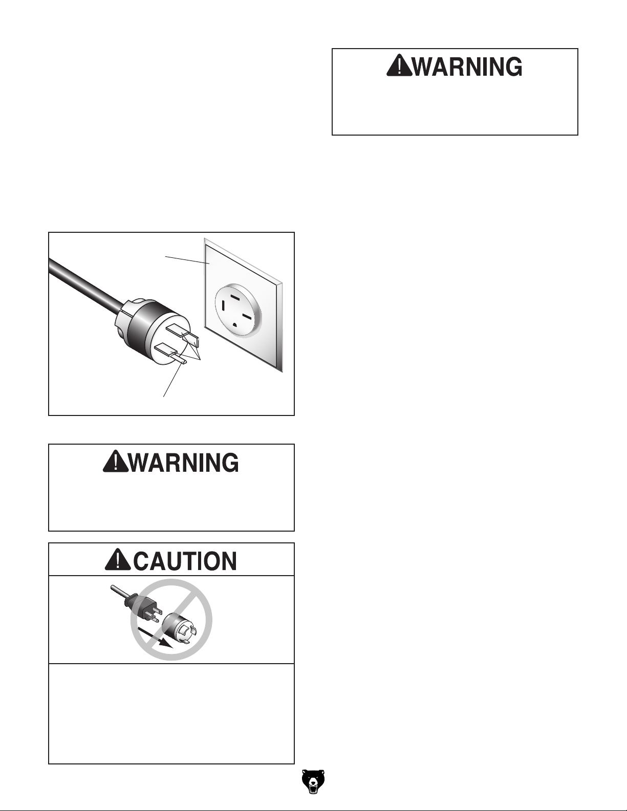
The power cord and plug specified under “Circuit
Requirements for 220V”
has an equipment-grounding wire and a grounding prong. The plug must only be inserted into
a matching receptacle (outlet) that is properly
installed and grounded in accordance with all
local codes and ordinances (see figure below).
No adapter should be used with the
required plug. If the plug does not fit the
available receptacle, or the machine must
on the previous page
Grounded
Outlet Box
Serious injury could occur if you connect
the machine to power before completing the
setup process. DO NOT connect to power
until instructed later in this manual.
Current
Carrying
Blades
Grounding Pin
Figure 9. Typical 15-20 plug and receptacle.
the machine to power before completing the
setup process. DO NOT connect to power
until instructed later in this manual.
be reconnected for use on a different type
of circuit, the reconnection must be made
by a qualified electrician and comply with all
local codes and ordinances.
-16 -
Extension Cords
If you must use an extension
Minimum Gauge Size ...........................12 AWG
Maximum Length (Shorter is Better).......50 ft.
Model G0740 (Mfg. Since 11/12)
Page 19
Correcting Phase
U1 V1 W1 E 0 2 3
Ground
1
4 5 6 7 8
V1
W1
E 0
A1
2
3
3
4 5
5
6
66778
4
8
4
4 5 6 7 8
33
E
W1V1
0
T
S
R
0 4 6322
A1
2
11
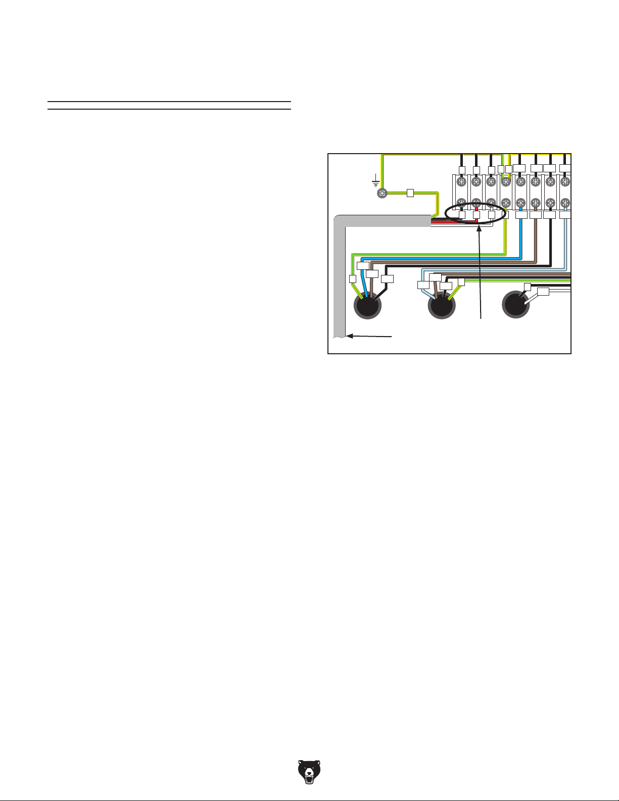
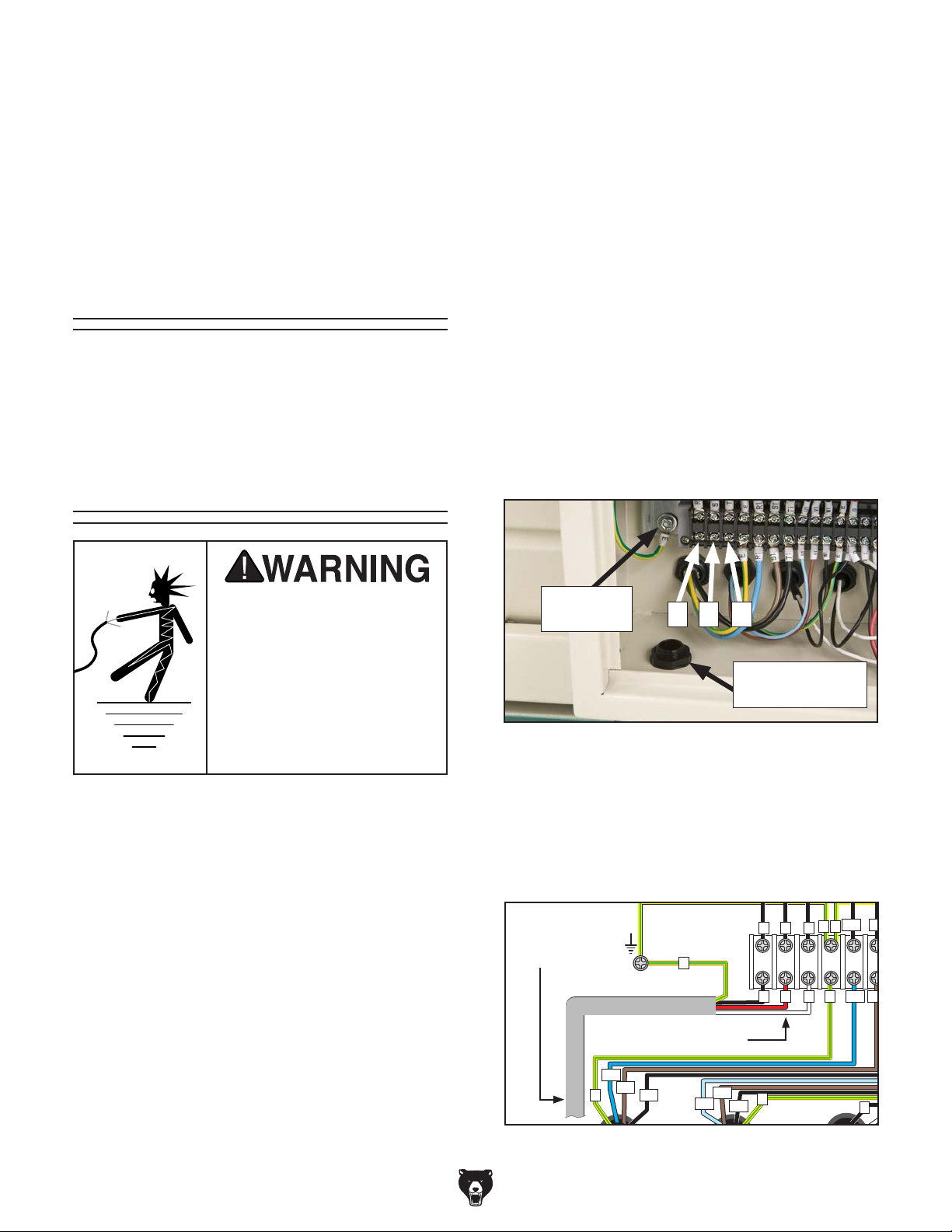
2. Open the electrical box and swap any two hot
wires R, S, T, as illustrated in Figure 10.
Polarity Wiring
This sub-section is only provided for troubleshooting. If you discover during the Test Run (Page
26), that the lathe will not operate, or that the
spindle runs backwards, the lathe may be wired
out of phase. Without the proper test equipment
to determine the phase of power source legs,
wiring machinery to 3-phase power may require
trial-and-error.
Correcting the phase polarity requires reversing
the positions where two of the incoming power
source wires are connected. Due to the high
voltage and risk of serious shock involved, we
strongly recommend this procedure only be done
by an electrician or qualified service personnel.
To correct wiring that is out of phase:
1. Push the STOP button, turn the two-speed
motor switch to OFF, and DISCONNECT
THE MACHINE FROM POWER!
Note: If using a phase converter for 220V
3-phase operation, ONLY swap the R and T
wires to correct out of phase wiring. The "wild
wire" is connected to the S terminal.
E
E
TR S
E
S1
E
U1
R S T E R1 S1 T1
R S
T R1R1S1
S1
E
W1
E
0
U1R1 S1 T1
T1T1U1
A1
Swap Any Two of
To Plug
These Wires
Figure 10. Swapping power connections to
correct out-of-phase wiring.
3. Close and latch the electrical box, and reconnect the machine to the power source.
Model G0740 (Mfg. Since 11/12)
-17-
Page 20

SECTION 3: SETUP
Your machine was carefully packaged for safe
transportation. Remove the packaging materials
from around your machine and inspect it. If you
discover any damage, please call us immediately
at (570) 546-9663
Save the containers and all packing materials for
possible inspection by the carrier or its agent.
Otherwise, filing a freight claim can be difficult.
When you are completely satisfied with the condi
tion of your shipment, inventory the contents.
Preparation
The list below outlines the basic process of preparing your machine for operation. Specific steps
are covered later in this section.
The typical preparation process is as follows:
1. Unpack the lathe and inventory the contents
of the box/crate.
2. Clean the lathe and its components.
3. Identify an acceptable location for the lathe
and move it to that location.
4. Level the lathe and either bolt it to the floor or
place it on leveling pads.
5. Assemble the loose components and make
any necessary adjustments or inspections to
ensure the lathe is ready for operation.
Needed for Setup
The following are needed to complete the setup
process, but are not included with your machine.
• For Lifting and Moving:
— A forklift or other power lifting device rated
for at least 3500 lbs.
— Two lifting straps rated for at least 3500 lbs.
each
— Guide rods for steading the load when lift-
ing (see Page 22)
— Two other people for moving machine
—Hardwood blocks (see Page 22)
• For Power Connection:
— A power source that meets the minimum cir-
cuit requirements for this machine (review
Power Supply on Page 15 for details)
— An electrician or qualified service person-
nel to ensure a safe and code-compliant
connection to the power source
6. Check/lubricate the lathe.
7. Connect the lathe to the power source.
8. Test run lathe to ensure it functions properly.
9. Perform the spindle break-in procedure to
prepare the lathe for operation.
Unpacking
-18-
for advice.
• For Assembly:
— Shop Rags
— Cleaner/degreaser (see Page 20)
— Quality metal protectant lubricant
— Safety glasses for each person
— Wrench or socket 21mm
— Wrench or socket 19mm
— Floor mounting hardware as needed (see
Page 24)
— Precision level at least 12" long
-
Model G0740 (Mfg. Since 11/12)
Page 21
Inventory
The following is a list of items shipped with your
machine. Before beginning setup, lay these items
out and inventory them.
If any non-proprietary parts are missing (e.g. a
nut or a washer), we will gladly replace them; or
for the sake of expediency, replacements can be
obtained at your local hardware store.
Keep children and pets away
from plastic bags or packing
materials shipped with this
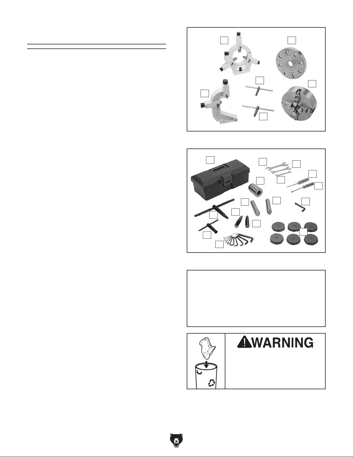
A B
Box 1: (Figure 11) Qty
A. Steady Rest Assembly (Installed) .............. 1
B. 10" Faceplate w/D1-5 Camlock Stud Set ... 1
C. 10" 4-Jaw Chuck w/Reversible Jaws.......... 1
D. 3-Jaw Chuck Key ....................................... 1
E. 4-Jaw Chuck Key ....................................... 1
F. Follow Rest Assembly (Installed) ............... 1
Tool Box Inventory: (Figure 12) Qty
G. Too l Box...................................................... 1
H. Open End Wrench 22/24mm ...................... 1
I. Open End Wrench 14/17mm ...................... 1
J. Open End Wrench 10/12mm ...................... 1
K. Phillips Screwdriver #2 ............................... 1
L. Standard Screwdriver #2 ............................ 1
M. Hex Wrench 8mm ....................................... 1
N. Tapered Spindle Sleeve MT#5-#3 .............. 1
O. Dead Center MT#3 ..................................... 1
P. Carbide-Tipped Dead Center MT#3 ........... 1
Q. Camlock Key D1-5 ...................................... 1
R. Tool Post T-Wrench (Clamped on Tool
Post) ........................................................... 1
S. Hex Wrench Set 1.5-10mm ........................ 1
T. Carriage Handwheel Handle ...................... 1
U. Cross Slide Handwheel Handle ................. 1
V. Cast Iron Leveling Pads ............................. 6
D
F
E
Figure 11. Main inventory.
G
O
Q
R
Figure 12. Toolbox inventory.
T
S
H
N
U
J
P
C
I
K
L
M
V
NOTICE
If you cannot find an item on this list, carefully check around/inside the machine and
packaging materials. Often, these items get
lost in packaging materials while unpacking or they are pre-installed at the factory.
Pre-Installed (Not Shown) Qty
• 8" 3-Jaw Chuck w/2-Pc. Jaw Set ............... 1
1
• 8
Model G0740 (Mfg. Since 11/12)
⁄4" Back Plate D1-5 .................................. 1
SUFFOCATION HAZARD!
machine. Discard immediately.
-19 -
Page 22
The unpainted surfaces of your machine are
coated with a heavy-duty rust preventative that
prevents corrosion during shipment and storage.
This rust preventative works extremely well, but it
will take a little time to clean.
Be patient and do a thorough job cleaning your
machine. The time you spend doing this now will
give you a better appreciation for the proper care
of your machine's unpainted surfaces.
There are many ways to remove this rust preven
tative, but the following steps work well in a wide
variety of situations. Always follow the manufac
turer’s instructions with any cleaning product you
use and make sure you work in a well-ventilated
area to minimize exposure to toxic fumes.
Before cleaning, gather the following:
•
•
•
•
Basic steps for removing rust preventative:
1.
2.
3.
4.
metal protectant to prevent rust.
Gasoline or products
Many cleaning solvents
ed amounts are inhaled.
Avoid chlorine-based solvents, such as
Cleanup
with low flash points can
explode or cause fire if
used to clean machinery. Avoid cleaning with
these products.
are toxic if concentrat-
Disposable Rags
Cleaner/degreaser (WD•40 works well)
Safety glasses & disposable gloves
Plastic paint scraper (optional)
Put on safety glasses.
Coat the rust preventative with a liberal
amount of cleaner/degreaser, then let it soak
for 5–10 minutes.
Wipe off the surfaces. If your cleaner/degreas-
er is effective, the rust preventative will wipe
off easily. If you have a plastic paint scraper,
scrape off as much as you can first, then wipe
off the rest with the rag.
-
-
Only work in a well-ventilated area.
NOTICE
acetone or brake parts cleaner, that may
damage painted surfaces. Test all cleaners
in an inconspicuous area before using to
make sure they will not damage paint.
T23692—Orange Power Degreaser
A great product for removing the waxy shipping
grease from your machine during clean up.
Repeat Steps 2–3 as necessary until clean,
then coat all unpainted surfaces with a quality
-20-
Figure 13. T23692 Orange Power Degreaser.
Model G0740 (Mfg. Since 11/12)
Page 23
Site Considerations
Weight Load
Physical Environment
Place this machine near an existing power source.
Shadows, glare, or strobe effects that may distract
Refer to the Machine Data Sheet for the weight
of your machine. Make sure that the surface upon
which the machine is placed will bear the weight
of the machine, additional equipment that may be
installed on the machine, and the heaviest workpiece that will be used. Additionally, consider the
weight of the operator and any dynamic loading
that may occur when operating the machine.
Space Allocation
Consider the largest size of workpiece that will
be processed through this machine and provide
enough space around the machine for adequate
operator material handling or the installation of
auxiliary equipment. With permanent installations,
leave enough space around the machine to open
or remove doors/covers as required by the maintenance and service described in this manual.
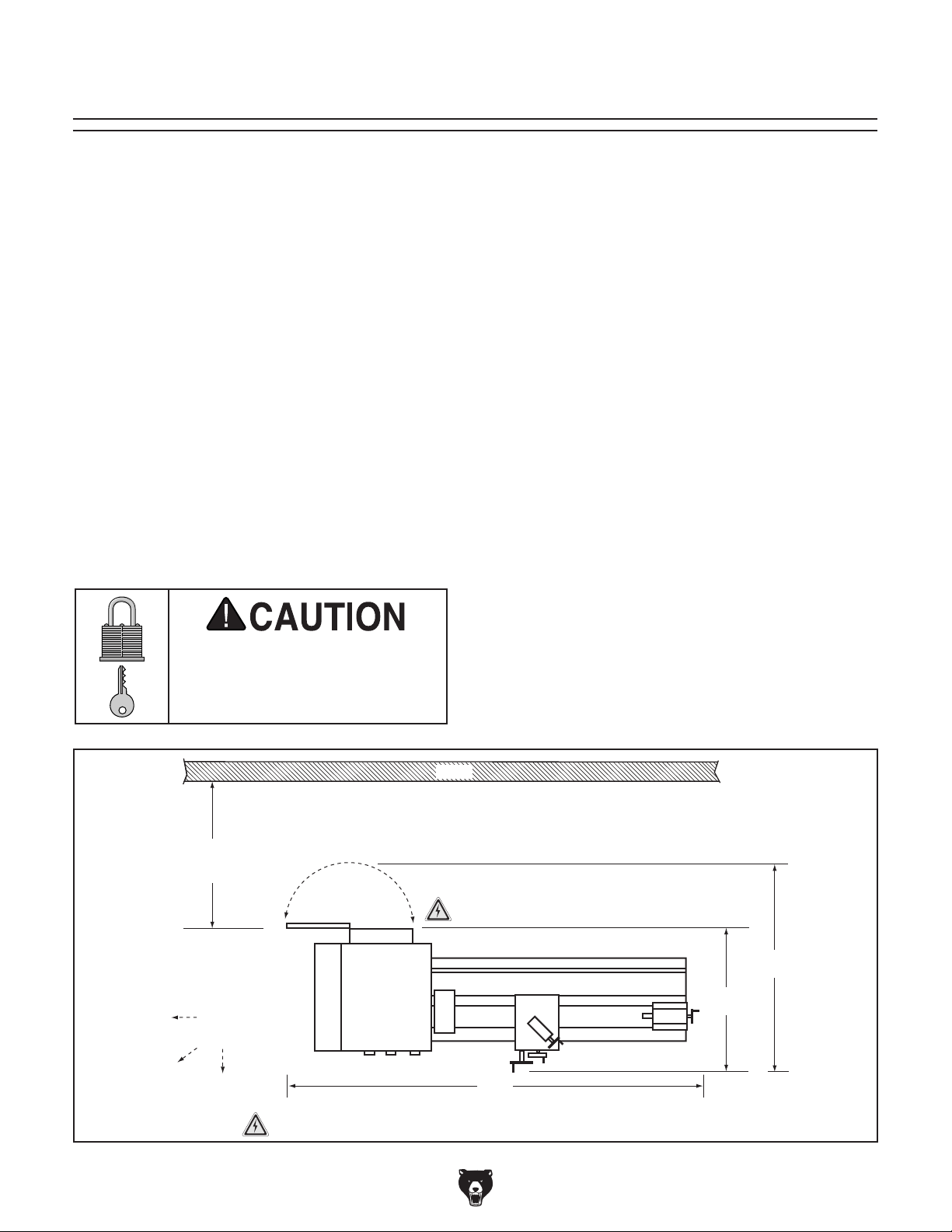
See below for required space allocation.
Children or untrained people
may be seriously injured by
this machine. Only install in an
access restricted location.
The physical environment where the machine is
operated is important for safe operation and longevity of machine components. For best results,
operate this machine in a dry environment that is
free from excessive moisture, hazardous chemicals, airborne abrasives, or extreme conditions.
Extreme conditions for this type of machinery are
generally those where the ambient temperature
range exceeds 41°–104°F; the relative humidity
range exceeds 20–95% (non-condensing); or the
environment is subject to vibration, shocks, or
bumps.
Electrical Installation
Make sure all power cords are protected from
traffic, material handling, moisture, chemicals,
or other hazards. Make sure to leave access to
a means of disconnecting the power source or
engaging a lockout/tagout device, if required.
Lighting
Lighting around the machine must be adequate
enough that operations can be performed safely.
or impede the operator must be eliminated.
Min. 30"
for Maintenance
Keep
Workpiece
Loading Area
Unobstructed
= Electrical Connections Illustration Not To Scale
Model G0740 (Mfg. Since 11/12)
Wall
Electrical
Cabinet
Lathe
84"
Figure 14. Minimum working clearances.
48"
32"
-21-
Page 24
Lifting & Moving
5. Position hardwood blocks under each end of
the bed as shown in Figure 15. This will keep
the lifting straps away from the leadscrew,
feed rod, and spindle rod to prevent bending
them during lifting.
(Looking at Lifting Setup from Tailstock End)
To Power Lifting Equipment
Lifting
Leadscrew
Strap
This machine and its parts are heavy!
Serious personal injury may occur if safe
moving methods are not used. To reduce
the risk of a lifting or dropping injury, ask
others for help, and use power equipment
and guide rods.
Do not attempt to lift or move this lathe without
using the proper lifting equipment (such as forklift
or crane) or the necessary assistance from other
people. Each piece of lifting equipment must be
rated for at least 25% more than the shipping
weight of your lathe to support dynamic loads that
may be applied while lifting. Refer to Needed for
Setup on Page 18 for details.
To lift and move the lathe:
Feed Rod
Control Rod
Hardwood
Blocks
& Planks
Positioned as
Required to
Prevent Lifting
Straps from
Bending
Leadscrew
Figure 15. Lifting setup to keep straps from
bending leadscrew or rods.
Note: Fasten a center support between the
hardwood blocks so that they will stay spread
apart and in place when lifting (see the example in Figure 16).
Center
Support
Lathe
Bed
1. Remove the shipping crate top and sides,
then remove the small components from the
shipping pallet.
2. Move the lathe to its prepared location while
it is still attached to the shipping pallet.
3. Unbolt the lathe from the shipping pallet
4. To balance the load for lifting, move the
tailstock and carriage to the extreme right
end of the bedway, then lock them in place.
Note: Before attempting to move the car-
riage, make sure the carriage lock is loose,
the half nut is disengaged, and the power
feed is disengaged (feed selection lever).
-22-
Hardwood
Blocking
Figure 16. Example of blocking center support.
Model G0740 (Mfg. Since 11/12)
Page 25
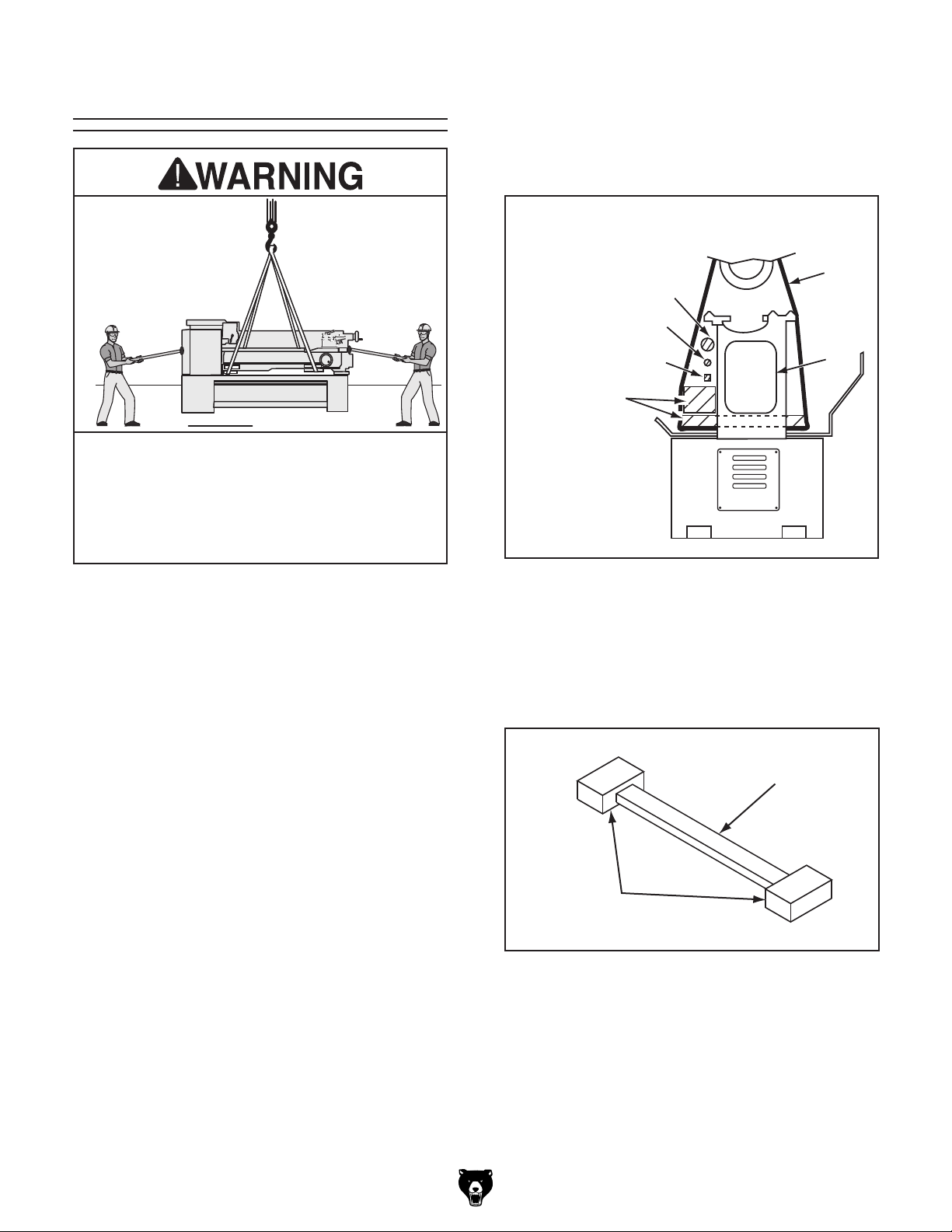
6. Attach the lifting straps to the power lifting
equipment (see Figure 17 for an example).
Leveling & Mounting
Use Blocks to Space Straps Away
from Control Rod, Feed Rod, Leadscrew &
Prevent Bending During Lifting
Power Lifting
Equipment
Lifting
Straps
Hardwood
Blocking
Figure 17. Example of lathe setup for lifting.
7. At each end of the lathe, have assistants con-
nect guide rods to safely keep the lathe from
swaying or tipping during lifting.
When lifting the lathe with straps, the load
will be top heavy. Take extra care to keep
the load balanced vertically and only lift the
lathe far enough to remove the shipping
pallet.
8. Raise the lathe a couple of inches and check
the balance of the load.
— If the load is not safely balanced, immedi-
ately lower the lathe and resolve the issue
before attempting to lift it again.
9. Raise the lathe enough to clear the shipping
pallet, carefully remove the pallet, then lower
the lathe into position.
Hardwood
Blocking
You must level your machine and either use the
included foot pads and leveling hardware or bolt
and shim your lathe to the floor. Because mounting your lathe to the floor with permanent hardware is an optional step and floor materials may
vary, floor mounting hardware is not included.
Leveling
For accurate turning results and to prevent
warping the cast iron bed and ways, the lathe
bedways MUST be leveled from side-to-side
and from front-to-back on both ends.
Re-check the bedways 24 hours after
installation, two weeks after that, and then
annually to make sure they remain level.
Leveling machinery helps precision components,
such as bedways, remain straight and flat during
the lifespan of the machine. Components on a
machine that is not level may slowly twist due to
the dynamic loads placed on the machine during
operation.
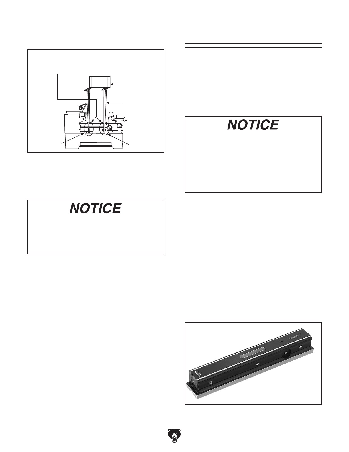
For best results, use a precision level that is at
least 12" long and sensitive enough to show a
distinct movement when a 0.003" shim (approximately the thickness of one sheet of standard
newspaper) is placed under one end of the level.
See the figure below for an example of a high
precision level.
Model G0740 (Mfg. Since 11/12)
Figure 18. Model H2683 precision level.
-23-
Page 26
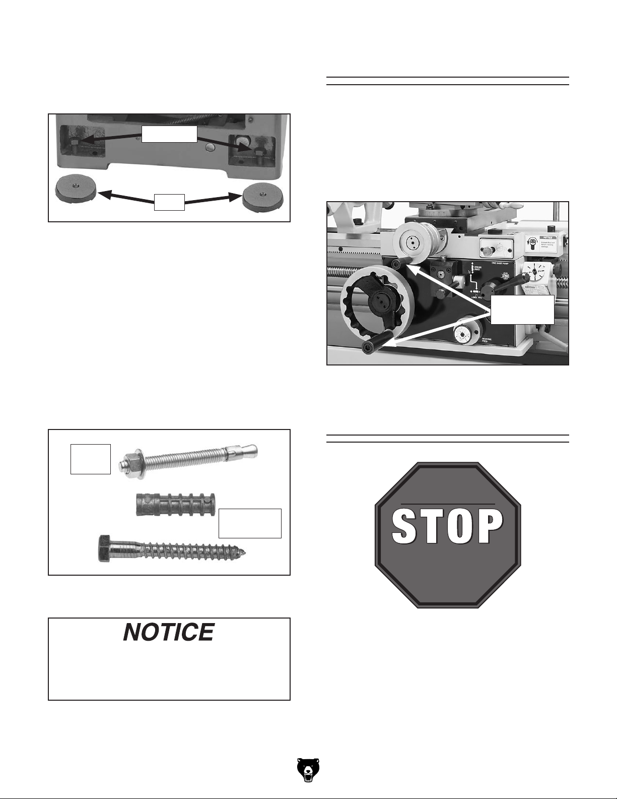
— If using the included leveling pads (see
the floor if it is permanently connected
Figure 19), place them under the six level-
ing jack bolt locations, then adjust the bolts
to level the lathe.
Assembly
With the exception of the handwheel handles, the
lathe is shipped fully assembled.
Jack Bolts
Pads
Figure 19. Leveling pads and screws.
— If using mounting hardware that does not
allow for adjustment, level the lathe by
placing metal shims between the lathe
base and the floor before bolting it down.
Bolting to Concrete Floors
Lag screws and anchors, or anchor studs (see
Figure 20), are two popular methods for bolting machinery to a concrete floor. We suggest
you research the many options and methods for
mounting your machine and choose the best one
for your specific application.
To install the handwheel handles, thread the large
handle into the carriage handwheel and the small
handle into the cross slide handwheel, as shown
in Figure 21.
Handwheel
Handles
Figure 21. Handwheel handles installed.
Lubricating Lathe
Anchor
Stud
Lag Screw
and Anchor
Figure 20. Typical fasteners for mounting to
concrete floors.
Unless otherwise specified by your local
codes, this machine MUST be secured to
(hardwired) to the power supply.
GEARBOXES MUST
BE FILLED WITH OIL!
LATHE MAY NOT
HAVE OIL INCLUDED!
Refer to the Lubrication
Section in this Manual
for Recommended
Oil Type.
The headstock, quick-change gearbox, and apron
oil reservoirs must have the proper amount of oil
in them before the lathe can be operated initially.
Damage caused to the bearings and gears from
running the lathe without oil in the reservoirs
will not be covered under warranty. Refer to the
Lubrication section, beginning on Page 65, for
checking and adding oil.
-24-
Model G0740 (Mfg. Since 11/12)
Page 27
In addition to the reservoirs, we also recommend
S1 T1 U1 V1 W1 E 0 2 3
Ground
1
4 5 6 7 8
S1
T1T1U1U1V1
W1
E 0
A1
334 5
5
6
66778
4
8
4 5 6 7 8
33
E
W1
V1U1
S1 T1
0
T
S
R
0 4 6322
A1
A1
2
11
that you lubricate all other points on the machine
at this time. This can be accomplished by following the maintenance schedule on Page 64.
Note: If this lathe was shipped with oil in the res-
ervoirs, do not change that oil until after the test
run and spindle break-in procedures.
Adding Coolant
Note About 3-Phase Power: Due to the startup
load from this machine, we do not recommend
using a static phase converter to create 3-phase
power—as it can quickly decrease the life of
electrical components on this machine. If you
must use a phase converter, only use a rotary
phase converter and connect the manufactured
leg or "wild wire" to the S terminal (see location in
Figures 22–23). The S terminal can handle power
fluctuation because it is wired directly to the motor.
To connect the power cord to the lathe:
Add the coolant of your choice now. For detailed
instructions on where the coolant tank is located
and how to add fluid, refer to Coolant System
Service on Page 70.
Power Connection
Electrocution or fire
may occur if machine is
ungrounded, incorrectly
connected to power, or
connected to an undersized
circuit. Use an electrician
or a qualified service
personnel to ensure a safe
power connection.
Before the machine can be connected to the
power source, an electrical circuit must be made
available that meets the minimum specifications
given in Circuit Requirements for 220V on Page
15. If a power circuit has not been prepared for the
machine, do that now.
To minimize the risk of electrocution, fire, or equipment damage, installation work and electrical wiring MUST be done by an electrician or qualified
service personnel.
Note About Extension Cords: Using an incor-
rectly sized extension cord may decrease the life
of electrical components on your machine. Refer
to Extension Cords on Page 16 for more information.
1. Press the STOP button, turn the two-speed
motor switch to the OFF position then open
the electrical cabinet door.
2. Identify the R, S, and T terminals and the
grounding terminal (see Figure 22).
Grounding
Terminal
R S
T
Incoming Power
Strain Relief
Figure 22. Location of hot wire terminals, ground
terminal and strain relief inside electrical cabinet.
3. Thread the power cord through the strain
relief shown in Figure 22.
4. Connect the incoming hot wires and ground
wire to the terminals shown in Figure 23.
R1
E
E
Incoming
Power Cord
Wires Connected
R1
S1
E
E
S1
W1
TR S
R S T E R1
R S
T R1
E
E
Figure 23. Ground and hot wires connected.
0
Model G0740 (Mfg. Since 11/12)
-25-
Page 28
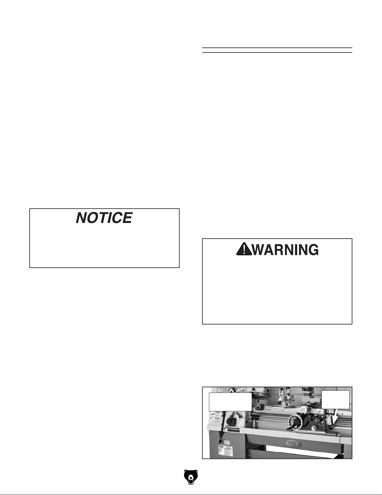
5. Make sure the power cord and wires have
slack between the strain relief and terminal
connections so that they do not bind, then
tighten the strain relief to secure the cord.
Note: The strain relief must be tightened
against the outer jacket of the cord. Avoid
over-tightening the strain relief or it may
crush the cord and cause a short.
Test Run
Once the assembly is complete, test run your
machine to make sure it runs properly and is
ready for regular operation.
The test run consists of verifying:
6. Test the strain relief to ensure it is properly
tightened by pulling the cord from outside the
box with light-to-moderate force. When the
strain relief is properly tightened, the cord will
not move inside the cabinet.
7. Install a NEMA 15-20 plug on the other end
of the power cord per the plug manufacturer's
instructions.
8. Close and lock the main electrical box door.
To avoid unexpected start-up of lathe
components, keep the two-speed motor
switch turned OFF and the STOP button
pressed in until instructed otherwise in the
Test Run.
9. Connect the plug to the matching receptacle
and power source as specified in Circuit
Requirements for 220V on Page 15.
• The motor powers up and runs correctly.
• The motor turns in the correct direction
(machine is not wired out of phase).
• The safety features work correctly.
• The brake system works correctly.
• The cutting fluid system works correctly.
If, during the test run, you cannot easily locate
the source of an unusual noise or vibration, stop
using the machine immediately, then review
Troubleshooting on Page 73.
Before starting the lathe, make sure you
have performed the preceding assembly
and adjustment instructions, and you have
read through the rest of the manual and
are familiar with the various functions and
safety features on this machine. Failure to
follow this warning could result in serious
personal injury or even death!
-26-
To test run your machine:
1. Make sure the two-speed motor switch (see
Figure 24) is turned OFF and the spindle
lever is in the OFF (middle) position.
Two-Speed
Motor Switch
Figure 24. Location of the two-speed switch.
Model G0740 (Mfg. Since 11/12)
Spindle
Lever
Page 29
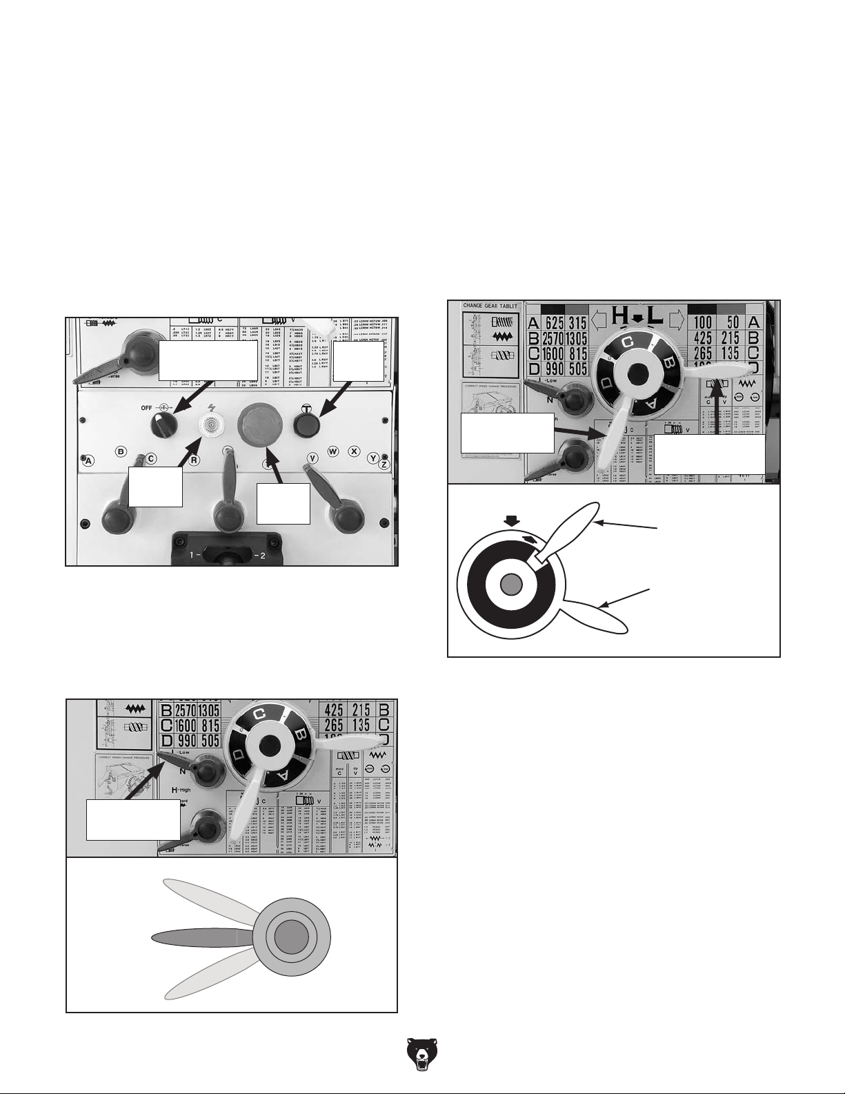
2. Clear away all tools and objects used during
assembly, lubrication, and preparation.
3. Make sure that the chuck and jaws, if installed,
are secure (refer to Chuck and Faceplate
Mounting on Page 32).
Note: If a chuck is not installed on the lathe,
you do not need to install one for this test.
4. Push the STOP button on the control panel
(see Figure 25), and point the coolant nozzle
into the chip pan.
Note: In the next step, use the chuck key
to rock the chuck back-and-forth so that the
gears will mesh as you make the adjustments. Be sure to remove the chuck key
before continuing.
6. Set the spindle speed to 50 RPM as follows:
a. Move the spindle range lever so that the
arrow on top of its hub is pointing toward
the right-hand spindle speed chart (see
Figure 27).
Cutting Fluid
Pump Switch
Jog
Button
Power
Lamp
STOP
Button
Figure 25. Control panel.
5. Disengage the quick-change gearbox from
the drive train by moving the feed range lever
to the neutral (middle) position (see Figure
26).
Speed
Speed Lever
Spindle Range
Lever
Spindle Speed
Lever Set To
“A” (50 RPM)
A
D
B
C
Spindle Range
Lever Pointing
To The Right-
Hand Speed
Chart
Figure 27. Spindle speed set to 50 RPM.
b. Move the spindle speed lever so that the
"A" on its hub is directly under the arrow on
the headstock. This corresponds to the "A"
in the right-hand spindle speed chart.
Feed
Range Lever
Low
Feed Range Lever
Neutral
High
Figure 26. Feed range lever.
Model G0740 (Mfg. Since 11/12)
c. Turn the two-speed motor switch to the
LOW position. This enables all the low
speeds in the green columns of the spindle
speed charts.
-27-
Page 30
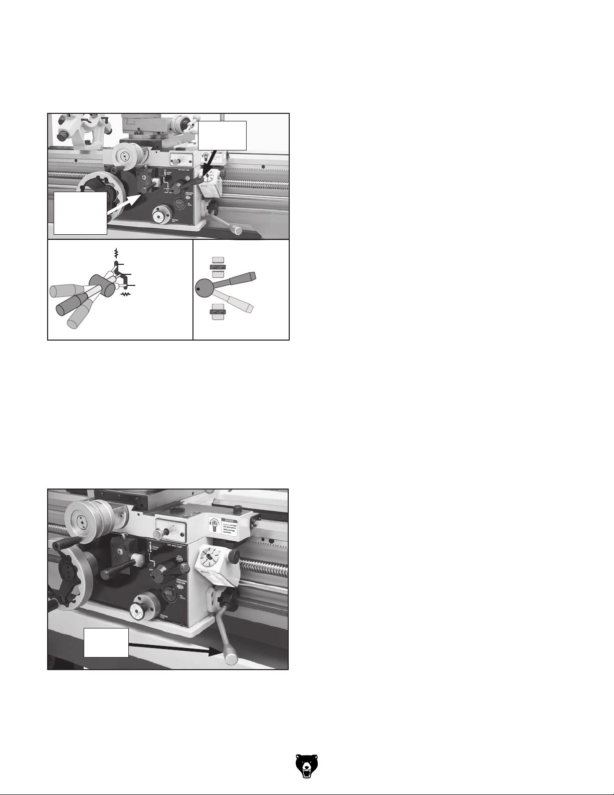
Disengaged
7. To ensure the carriage components do not
unexpectedly move during the following
steps, disengage the half nut lever and feed
selection lever (see Figure 28).
Half Nut
Lever
Feed
Selection
Lever
Cross Slide
Carriage
Feed Selection
Lever
Figure 28. Disengaging carriage components.
8. Reset the STOP button by twisting it clock-
wise until it pops out. The power lamp on the
control panel should illuminate.
9. Verify that the machine is operating correctly
by pulling the spindle lever out and moving
it down to start spindle rotation (see Figure
29).
Disengaged
Halfnut
Lever
Engaged
— When operating correctly, the machine
runs smoothly with little or no vibration or
rubbing noises.
— Investigate and correct strange or unusual
noises or vibrations before operating the
machine further. Always disconnect the
machine from power when investigating or
correcting potential problems.
10. With the spindle lever in the down position, the
spindle should be rotating counterclockwise—
down and toward you as you face the lathe.
— If the spindle and chuck are not rotating
counterclockwise, the power supply
is connected out-of-phase. Stop the
machine, disconnect it from power, then
follow the instructions in the Correcting
Phase Polarity section on Page 17. After
correcting the wiring, repeat Steps 7–10.
11. Press the STOP button to turn the lathe OFF,
then, without resetting the STOP button, try
to restart spindle rotation. The spindle should
not start.
— If spindle rotation does start with the STOP
button pressed in, the STOP button safety is
not operating correctly. This safety feature
must operate properly before continuing
operation. Use the spindle lever to stop the
lathe, disconnect it from power, and call
Tech Support for help.
Spindle
Lever
Figure 29. Spindle lever in down (forward)
position.
-28-
12. Move the spindle lever to the OFF (middle)
position, reset the STOP button by twisting
it clockwise until it pops out, then restart
spindle rotation.
13. Push the foot brake. The spindle should
come to a quick stop.
— If the brake pedal has no effect on the
lathe, push the STOP button, and refer to
Brake & Switch on Page 80 to make any
required adjustments.
14. Move the spindle lever to the OFF (middle)
position. Remove the end gear cover from
the left side of the headstock. This activates a
safety switch that should prevent the spindle
from starting while this cover is removed.
Model G0740 (Mfg. Since 11/12)
Page 31

15. Stand away from all the exposed gears on
the side of the headstock, and attempt to
start spindle rotation. The spindle should not
start.
— If spindle rotation does start with the end
cover removed, the safety switch is not
operating correctly. This safety feature
must operate properly before continuing
operation. Press the STOP button to turn
the lathe OFF, disconnect it from power,
and call Tech Support for help.
16. Push the STOP button in, move the spindle
lever to the OFF position, then replace the
end gear cover.
17. Lift the chuck guard up—this will activate the
chuck guard safety switch. Reset the STOP
button and attempt to start spindle rotation.
The spindle should not start.
— If spindle rotation does start with the chuck
guard in the up position, the safety switch is
not operating correctly. This safety feature
must operate properly before continuing
operation. Press the STOP button to turn
the lathe OFF, disconnect it from power,
and call Tech Support for help.
Spindle Break-In
Before subjecting the lathe to full loads, it is
essential to complete the spindle break-in process
as described below. This will ensure the best
results and maximum life of the precision components inside the lathe.
The break-in procedure must be performed in succession with the Test Run procedure described in
this manual, because many of the test run steps
prepare the lathe controls for the break-in process.
Important: Do not perform the break-in procedure
independently from the Test Run section—serious
damage could occur to the lathe if the controls are
set differently than instructed in that section.
Do not leave the lathe unattended during
the Spindle Break-In procedure. If your
attention is needed elsewhere during this
procedure, stop the lathe and restart the
procedure later from the beginning.
18. Use the cutting fluid pump switch on the con-
trol panel to start the pump, then open the
valve. Verify that the cutting fluid flows from
the nozzle, turn the pump OFF, then move
the spindle lever to the OFF position.
Congratulations! The test run is complete. Turn
the lathe OFF and perform the following Spindle
Break-In procedure.
After the first 16 hours of use, the V-belts
will stretch and seat into the pulley grooves.
The V-belts must be properly re-tensioned
after this period to avoid reducing their
useful life. Refer to the V-Belts subsection
on Page 79 for detailed instructions.
To perform the spindle break-in:
1. Successfully complete the Test Run proce-
dure beginning on Page 26.
2. Using the spindle speed levers to set the
spindle speed, run the lathe for 10 minutes
at each of the spindle speeds, starting at the
slowest.
Note: If necessary, refer to Setting Spindle
Speed on Page 51 for detailed instructions.
3. Use the foot brake to stop spindle rotation,
set the spindle speed at 2570 RPM, then use
the spindle lever to reverse the spindle rotation and run the lathe for 10 minutes.
Model G0740 (Mfg. Since 11/12)
-29-
Page 32

4. Use the foot brake to stop spindle rotation,
then run the lathe at 215 RPM for 10 minutes
with the gearbox range lever on the headstock in the L (low) position, and then run the
lathe another 10 minutes with the lever in the
H (high) position.
5. While the oil is still warm and any metal par-
ticles are still suspended in the oil, change
the headstock and gearbox oil (refer to
Lubrication beginning on Page 65 for
detailed instructions).
6. Check the V-belt tension, and if necessary,
re-tension them (refer to V-Belts on Page 79
for detailed instructions).
Recommended
Adjustments
The following adjustments have been made at the
factory. However, because of the many variables
involved with shipping, we recommend that you
at least verify the following adjustments to ensure
the best possible results from the lathe.
Step-by-step instructions for these adjustments
can be found on the pages referenced below.
Factory adjustments that should be verified:
Congratulations! The spindle break-in is complete.
• Tailstock alignment (see Page 40).
• Compound and cross slide backlash adjustment (see Page 76).
• Gib adjustments (see Page 77).
-30-
Model G0740 (Mfg. Since 11/12)
Page 33

SECTION 4: OPERATIONS
The purpose of this overview is to provide the novice machine operator with a basic understanding
of how the machine is used during operation, so
the
discussed later
in this manual
Due to the generic nature of this overview, it is
not intended to be an instructional guide. To learn
more about specific operations, read this entire
manual and
rienced
research outside of this manual by reading "howto" books, trade magazines, or websites.
To reduce your risk of
serious injury, read this
entire manual BEFORE
Operation Overview
machine controls/components
are easier to understand.
To complete a typical operation, the operator
does the following:
1. Puts on safety glasses, rolls up sleeves,
removes jewelry, and secures any clothing,
jewelry, or hair that could get entangled in
moving parts.
2. Examines the workpiece to make sure it is
suitable for turning, then securely mounts
the workpiece in one of the chucks or on the
faceplate, and removes the chuck key.
seek additional training from expe
machine operators, and do additional
using machine.
To reduce the risk of
eye injury from flying
chips always wear safety
glasses.
If you are not experienced with this type
of machine, WE STRONGLY RECOMMEND
that you seek additional training outside of
this manual. Read books/magazines or get
formal training before beginning any projects. Regardless of the content in this section, Grizzly Industrial will not be held liable
for accidents caused by lack of training.
3. Mounts the tooling, aligns it with the workpiece,
then backs it away to establish a safe startup
clearance.
4. Clears all setup tools from the lathe.
5. Checks for safe clearances by rotating the
workpiece by hand at least one full revolution.
6. Moves slides to where they will be used during operation.
7. Sets the correct spindle speed for the operation.
8. If using power feed, selects the proper feed
rate for the operation.
9. Turns the two-speed motor switch ON (HIGH
or LOW position), resets the STOP button,
then moves the spindle lever down to start
spindle rotation.
10. Uses the carriage handwheels or power feed
options to move the tooling into the workpiece
for operations.
11. When finished cutting, moves the spindle
lever to the OFF position, presses the foot
brake to completely stop the spindle, then
removes the workpiece.
Model G0740 (Mfg. Since 11/12)
-31-
Page 34

Chuck & Faceplate
Pre-Threaded Hole
for Lifting Eye
Way Slot
Jaw Slot
Plywood & 2x4
Chuck Cradle
Plywood Chuck Cradle
(Straight Cuts)
Plywood Chuck Cradle
(Curved Cuts)
Fabricated Steel
Lifting Hook
Solid Block
Chuck Cradle
Plywood Protection
Plate for Chucks
Installed by Hand
MEDIUM-SIZE, HEAVY CHUCKS
LARGE, VERY HEAVY CHUCKS
SMALL, LIGHTWEIGHT CHUCKS
Because chucks are heavy and often awkward
to hold, some kind of lifting, support, or protective device should be used during installation or
removal. The weight and size of the chuck will
determine the appropriate device to use (refer to
the following figure for examples).
This lathe is equipped with a D1-type spindle
nose. This type of spindle uses camlocks that are
adjusted with a chuck key to securely mount a
chuck or faceplate with repeatable precision and
ease.
This lathe ships with the 3-jaw chuck installed.
This is a scroll-type chuck where all three jaws
move in unison when the chuck key is used.
The included 4-jaw chuck features independent
jaws, which are used for square or unevenlyshaped stock, and to mount work that needs to be
adjusted to near zero total indicated runout.
If neither chuck can hold your workpiece, the
cast iron faceplate has slots for T-bolts that hold
standard or custom clamping hardware. With the
correct clamping hardware, a faceplate offers a
wide range of uses, including machining nonconcentric workpieces, straight turning between
centers, off-center turning, and boring.
Never use spindle speeds faster than the
chuck RPM rating or the safe limits of
your workpiece. Excessive spindle speeds
Installation &
Mounting
greatly increase the risk of the workpiece or
chuck being thrown from the machine with
deadly force!
Removal Devices
A dropped chuck can cause amputation,
serious crushing injuries, or property damage. Always use a support or protective
device to reduce this risk when installing or
removing a chuck.
-32-
Figure 30. Examples of common devices used
during chuck installation and removal.
Model G0740 (Mfg. Since 11/12)
Page 35

Chuck Installation
To ensure accurate work, it is extremely important
to make sure the spindle nose and chuck mating
surfaces/tapers are clean. Even a small amount of
lint or debris can affect accuracy.
The chuck is properly installed when all camlocks
are tight, the spindle and chuck tapers firmly
lock together, and the back of the chuck is firmly
seated against the face of the spindle all the way
around—without any gaps.
5. Incrementally tighten the camlocks in a crisscross or star pattern to ensure that the chuck
6.
nose, as shown in the following figure.
— If the cam line is NOT between the "V"
positions on the chuck.
To install the chuck:
1.
2.
Installation & Removal Devices
3.
4.
Avoid inserting the studs by pivoting them in from an angle or rotating the
spindle. This can damage studs or spindle
cam holes.
DISCONNECT LATHE FROM POWER!
seats evenly against the spindle.
When the chuck is fully seated and all the
camlocks are tight, verify that the cam line
is between the two “V” marks on the spindle
Use an appropriate lifting, support, or protec-
tive device to protect the ways and support
the chuck during the installation process
(refer to the
section in this Manual).
Clean and lightly oil the camlock studs, then
thoroughly clean the mating surfaces of the
spindle and chuck.
Install the chuck by inserting the camlock
studs straight into the spindle cam holes.
Important:
Cam line between “V”s
Figure 32. Cam line positioned between the "V"
marks after the camlocks are fully tightened.
marks when the camlock is tight, the stud
may be installed at the incorrect height.
To fix this, adjust the stud height as
shown in the following figure. Make sure
to re-install the stud cap screw afterward.
— If adjusting the stud height does not
correct the problem, try swapping stud
INCORRECTCORRECT
INCORRECT INCORRECT
Figure 31. Inserting camlock studs into spindle
cam holes.
Model G0740 (Mfg. Since 11/12)
Stud Too High:
Turn In
One-Turn
Figure 33. Correcting an improperly installed
stud.
Stud Too Low:
Turn Out
One-Turn
-33-
Page 36

Lightly stamp registration marks across the
mating seams of chuck components
marks will help you re-install the chuck in the
same position after removal, which ensures
consistent chuck balance and turning results, and
allows the same camlocks and studs to operate
together for consistent locking and unlocking.
7. Verify that the chuck fits the spindle properly
by checking for any gaps between the mating
surfaces.
8.
our Tech Support.
To remove the chuck:
1.
2.
Installation &
3.
mark, as shown in the Figure below.
Tip: Camlocks can become very tight. A
cheater pipe may be used as a last resort to
add leverage when loosening. After loosening, you may need to wiggle the chuck key in
4.
5.
— If the chuck does not immediately come off,
rotate it approximately 60° and tap it again.
—If there are no gaps, proceed to Step 8.
Chuck Removal
—If there is a gap, remove the chuck, re-
clean the mating surfaces carefully, and
re-install. If the problem persists, contact
our Tech Support.
Verify that the chuck/spindle tapers are seat-
ed firmly together by removing the chuck,
per the Chuck Removal instructions, and
pay close attention to how easily the tapers
release.
—If it was necessary to bump the chuck or
use a mallet to release the tapers, then
they are seating together properly.
—If the tapers released easily with little
intervention, they are not seated together
firmly as required. Remove the chuck, reclean the mating surfaces carefully, and
re-install. If the problem persists, contact
DISCONNECT LATHE FROM POWER!
Use an appropriate lifting, support, or pro-
tective device to protect the ways and support the chuck (refer to the
Removal Devices section in this manual).
Loosen the camlocks by turning the key
counterclockwise until each of the cam lines
are aligned with its corresponding spindle
Cam line aligned with spindle mark
Registration Marks
Camlock
Spindle
Marks
for Chuck
Reassembly
Figure 34. Registration mark locations.
-34-
Spindle & Chuck
Registration Marks
. These
Chuck
Halves
2-Piece
Direct Mount
Camlock Chuck
Figure 35. Camlock is fully loosened when the
cam line is aligned with the spindle mark.
the camlock to fully disengage the stud.
Using a dead blow hammer or other soft
mallet, lightly tap around the outer circumference of the chuck body to loosen it from the
spindle.
Remove the chuck from the spindle, using
a light rocking motion to carefully slide the
studs out of the cam holes.
Make sure all the marks on the cams and
spindle are in proper alignment for remov-
Model G0740 (Mfg. Since 11/12)
Page 37

This 3-jaw scroll-type chuck has an internal
scroll-gear
a
cylindrical parts on-center with the axis of spindle
rotation and can be
workpiece is properly clamped and balanced.
Never mix jaw types or
accommodate an odd-shaped workpiece.
chuck will spin out of balance an
the workpiece
chuck or a faceplate.
Scroll Chuck
This chuck has 2-piece jaws that consist of
a top jaw and a master jaw. The top jaw can
be removed, rotated 180°, and re-installed in
the reverse position for additional work-holding
options. When reversing the top jaws, always
keep them matched with their original master jaw
to ensure the best fit.
To reverse 2-piece jaws:
1.
2.
3
install it with the longest cap screw in the tall-
4
time to keep all original parts together).
Clamping
that moves all jaws in unison when
djusted with the chuck key. This chuck will hold
rotated at high speeds if the
Chuck Jaw Reversal
Safer Inside
Jaw Use
CORRECT
Safer Outside
Jaw Use
CORRECT
Safer Outside
Jaw Use
positions to
The
d may throw
! Instead, use an independent jaw
Insufficient
Jaw Clamping
Bar Stock
Unsafe Jaw Position and
Poor Scroll Gear Engagement
Shallow
Bar Stock
Unsafe Inside
Unstable
Workpiece
INCORRECT
Poor Grip
Unstable
Workpiece
INCORRECT
Jaw Use
DISCONNECT MACHINE FROM POWER!
Remove the cap screws that secure the top
jaw to the master (bottom) jaw.
. Remove the top jaw, rotate it 180°, then re-
est portion of the jaw.
. Repeat Steps 2–3 with each remaining jaw
(we recommend only reversing one jaw at a
Long Cap ScrewShort Cap Screw
Rotate Top
Jaw 180º
Master Jaw
Poor Scroll
Shallow
Bar Stock
Unsafe Jaw
CORRECT
Safer Inside
Jaw Use
Position
Unsafe Jaw Position
Gear
Engagement
INCORRECT
Cylinder
CORRECT
Figure 36. Jaw selection and workpiece holding.
Model G0740 (Mfg. Since 11/12)
Poor Scroll
Gear Engagement
INCORRECT
Figure 37. Reversing the chuck jaws.
-35-
Page 38

4-Jaw Chuck
Refer to the prior Chuck Installation and Chuck
Removal
removing the 4-jaw chuck.
The 4-jaw chuck features independently adjustable hardened steel jaws for holding non-concentric or off-center workpieces. Each jaw can
be independently removed from the chuck body
and reversed for a wide range of work holding
versatility.
Mounting Workpiece
1.
2.
3.
workpiece will lay flat against the chuck face,
4.
tered in the chuck.
5. Tighten each jaw in small increments. After
tightening the remaining jaws in an opposing
in the Figure below.
6. After the workpiece is held in place by the
make fine adjustments by slightly loosening
(see the Figure below for an example).
sections for instructions on installing or
you have adjusted the first jaw, continue
sequence, as shown by the sequential order
Because of the dynamic forces involved in
machining a non-concentric or off-center
workpiece, always use a low spindle speed
to reduce risk of the workpiece coming loose
and being thrown from the lathe, which could
cause death or serious personal injury.
DISCONNECT LATHE FROM POWER!
Place a chuck cradle or plywood on the bed-
way below the chuck to protect the bedway
surfaces.
1
4
Figure 38. 4-jaw tightening sequence.
jaws, use a dial indicator to make sure the
workpiece is centered in the chuck.
— If the workpiece is not correctly centered,
one jaw and tightening the opposing jaw
until the workpiece is correctly positioned
3
Workpiece
Center Point
2
Use the chuck key to open each jaw so the
jaw steps, or into the spindle opening.
With help from another person or a holding
device, position the workpiece so it is cen-
-36-
Figure 39. Generic picture of non-cylindrical
workpiece correctly mounted on the 4-jaw chuck.
Model G0740 (Mfg. Since 11/12)
Page 39

Faceplate
Refer to the prior Chuck Installation and Chuck
Removal
removing the faceplate.
The faceplate included with your lathe can be
used for a wide range of operations, including
machining non-concentric workpieces, straight
turning between centers, off-center turning, and
boring.
The tools needed for mounting a workpiece will
vary depending on the type of setup you have.
To mount a non-concentric workpiece to the
faceplate:
1.
2.
3.
If necessary, use counter-weights to balance
the assembly and use a dial indicator to make
sure that the workpiece is properly positioned
for your operation.
DISCONNECT LATHE FROM POWER!
sections for instructions on installing or
Machining non-concentric workpieces at a
high speed could cause the workpiece to be
thrown from the spindle with deadly force
at the operator or bystanders. To reduce
this risk, only machine non-concentric
workpieces at low speeds and clamp
counter-weights to the faceplate to balance
it.
Protect the bedway with a piece of plywood.
With help from another person or a holding
device to support the workpiece, position it
onto the faceplate and clamp it in place with
a minimum of three independent clamping
devices (see Figure below for an example).
Be sure to take into account the rotational
and cutting forces that will be applied to the
workpiece when clamping it to the faceplate.
Non-Cylindrical
Workpiece
Failure to properly secure a workpiece to
the faceplate could cause the workpiece to
be thrown from the lathe with deadly force at
the operator or bystanders. Use a minimum
of THREE independent clamping devices to
hold the workpiece onto the faceplate.
Model G0740 (Mfg. Since 11/12)
Clamp
Faceplate
Figure 40. Generic picture of workpiece clamped
in a faceplate.
-37-
Page 40

Tailstock
The tailstock (see Figure below) is typically used
to support long workpieces by means of a live or
dead center (refer to
in the following section). It can also be used to hold a drill or chuck to
bore holes in the center of a part. Custom arbors
and tapers can also be cut on your lathe by using
the offset tailstock adjustment.
1. Pull the tailstock lock lever backward (away
bedway.
1. Move the quill lock lever away from the spin-
2.
3.
secure the quill in place.
This tailstock uses a quill with an MT#3 taper that
has
s
tang
below
for examples).
Centers
Using Quill
dle to unlock the quill.
Turn the quill handwheel clockwise to move
the quill toward the spindle or counterclockwise to move it away from it.
Move the lock lever toward the spindle to
Quill Lock
Lever
Figure 41. Tailstock and quill lock levers in
locked position.
Graduated Dial
Increments ................................................. 0.001"
One Full Revolution ................................... 0.100 "
Increments on Quill
Inch ..............................0"-4
Metric .................... 0–114mm in 1mm Increments
Tailstock Lock
Lever
Quill
Handwheel
1
⁄2 in 1⁄16" Increments
Installing Tooling
a lock slot in the back of the bore that accept
arbors and drill bits (see the Figures
Solid
End
Figure 42. Types of tapered arbors and tooling.
Open
End
Tang
Solid
End
Screw
End
Tang
Positioning Tailstock
from the spindle) to unlock the tailstock from
the bedway.
2. Slide the tailstock to the desired position.
3. Push the tailstock lock lever forward (toward
the spindle) to lock the tailstock against the
-38-
Figure 43. Example photos of inserting tools
with tangs into the tailstock.
Model G0740 (Mfg. Since 11/12)
Page 41

To install tooling in the tailstock:
1.
2. Thoroughly clean and dry the tapered mating
Note: If the tapered tool shaft has a tang,
align it with the slot in the back of the quill
3.
into the quill. Check to see if it is firmly seated
4.
5.
lever, then turn the quill handwheel clockwise
to feed the tool into the workpiece.
However, other tooling without tangs, such as
the four remaining tools shown previously, can
still be used
if the potential load will not
exceed
the strength of the tapered fit. For example, this
includes smaller
ters
Note: If the tooling has an open hole in the end
but is too short to be exposed in the drift slot for
removal, then a screw can be threaded into the
end of the tool to provide a solid surface
for the
quill pin
the quill is retracted
for tool removal. Otherwise, removal of such tooling may be difficult.
1. Use a shop rag to hold the tool.
2.
ing the quill, extend the quill and use a drift
below
The tailstock can be offset from the spindle centerline for turning tapers. Move the tailstock top
casting toward the front of the lathe to machine a
taper at the tailstock end. Conversely, move the
tailstock top casting toward the back of the lathe
to machine a taper at the spindle end
Note: The marks on the offset indicator are arbitrary. For a precise offset, use a dial indicator to
check quill movement while adjusting the screws.
Removing Tooling
drill chucks, drill bits, and cen-
.
to push against when
With the tailstock locked in place, unlock the
quill, then use the handwheel to extend it
approximately 1".
surfaces of the quill and the center, making
sure that no lint or oil remains on the tapers.
Rotate the quill handwheel counterclockwise
until the tool is forced out of the quill.
— If the tool does not come loose by retract-
key in the slot shown in the Figure
Drift Key Slot
Figure 44. Drift key slot in the side of the quill.
Offsetting Tailstock
before seating it.
With a firm and quick motion, insert the tool
by attempting to twist it—a firmly seated tool
will not twist.
Unlock the tailstock and move it until the tip
of the tool is close to, but not touching, the
workpiece, then re-lock the tailstock.
Start spindle rotation, unlock the quill lock
Model G0740 (Mfg. Since 11/12)
.
Tools Needed Qty
Hex Wrench 6mm .............................................. 1
Wrench 17mm.................................................... 1
-39-
Page 42

3. Retighten the clamping hex bolts underneath
2. Rotate the adjustment set screws in opposite
(see the illus-
tration below).
To offset the tailstock:
1.
Loosen the hex bolts underneath both ends
shown in the Figure below.
This is an essential adjustment that should be verified or performed each time the tailstock is used
to turn concentric workpieces between centers
or immediately after offsetting the tailstock when
turning a taper. If the tailstock is not aligned with
the spindle centerline when it is supposed to be,
turning results will be inaccurate along the length
of the workpiece.
To align the tailstock to the spindle centerline:
1.
dition before continuing with this procedure
section
2.
3.
illustrated in the Figure below.
of the tailstock to release the clamping pressure between the top and bottom castings
Adjustment
Set Screw
(1 of 2)
Offset
Indicator
Hex Bolt
(1 of 2)
Aligning Tailstock to Spindle
Centerline
Items Needed Qty
Hex Wrench 6mm .............................................. 1
Wrench 17mm.................................................... 1
Round Stock 2" x 6" .......................................... 2
Precision Level .................................................. 1
Figure 45. Tailstock offset controls.
directions for the desired offset
Turn
CCW
Figure 46. Set screw adjustment in relation to
Turn
CW
tailstock movement.
Turn
CW
Turn
CCW
Use the precision level to make sure the
bedway is level from side-to-side and from
front-to-back.
— If the bedway is not level, correct this con-
(refer to the Leveling & Mounting
in this manual).
Center drill both ends of one piece of round
stock, then set it aside for use in Step 5.
Use the other piece of round stock to make
a dead center, and turn it to a 60° point, as
-40-
Figure 47. Turning a dead center.
Model G0740 (Mfg. Since 11/12)
Page 43

Note: As long as this dead center remains in
the chuck, the point of the center will remain
true to the spindle centerline. The point will
have to be refinished whenever the center is
removed and then returned to the chuck.
4.
5.
, then mount it between the centers as
shown in the Figure below.
6. Turn 0.010" off the stock diameter.
7.
Note: If necessary in the following step, refer
subsection for
8. Use calipers to measure both ends of the
of
taper, as shown in the Figure below.
— If the test stock is thinner at the tailstock
of
taper, as shown in the Figure below.
9. Repeat Steps 6–8 until the desired accuracy
Install a center in the tailstock.
Attach a lathe dog to the test stock from
Step 2
workpiece.
— If the test stock is thicker at the tailstock
end, move the tailstock toward the front
the lathe 1⁄2 the distance of the amount of
Move tailstock toward
front of lathe half the
amount of taper
Looking down from above.
Figure 49. Adjust tailstock toward the operator.
Figure 48. Example photo of stock mounted
between the centers.
Mount a test or dial indicator so that the
plunger is on the tailstock quill.
to the Offsetting Tailstock
Model G0740 (Mfg. Since 11/12)
end, move the tailstock toward the back
the lathe 1⁄2 the distance of the amount of
Looking down from above.
Move tailstock toward
back of lathe half the
amount of taper
Figure 50. Adjust tailstock away from the
operator.
-41-
Page 44

Centers
Figure 51 shows the MT#3 dead centers includ-
ed with the lathe. In addition, an MT#5–MT#3
tapered spindle sleeve is included for mounting in
the spindle.
Dead
Center
Live Centers
A live center has bearings that allow the center
tip and the workpiece to rotate together; it can be
installed in the tailstock quill for higher speeds.
However, a live center typically does not provide
the same level of rigidity as a dead center, and
final workpiece accuracy can suffer as a result.
Mounting Dead Center in Spindle
1. DISCONNECT LATHE FROM POWER!
2. Thoroughly clean and dry the tapered mating
surfaces of the spindle bore, adapter sleeve,
and the center, making sure that no lint or oil
remains on the tapers.
Carbide Tipped
Dead Center
Adapter
Sleeve
Figure 51. Adapter sleeve and dead centers.
Dead Centers
A dead center is a one-piece center that does not
rotate with the workpiece and is used to support
long, slender workpieces
Use the dead center in the spindle for operations
where the workpiece rotates with the center and
does not generate friction.
The carbide-tipped dead center can better withstand the effects of friction and is best used in the
tailstock where the workpiece will rotate against
it. The tip of the center must be generously lubricated during the operation to avoid premature
wear and maximize smooth operation. Using low
spindle speeds will also reduce the heat and wear
from friction.
Note: This will prevent the tapered surfaces
from seizing due to operational pressures,
which could make it very difficult to remove
the center.
3. Mount a chuck or faceplate onto the spindle,
whichever is correct for your operation.
4. Insert the center into the sleeve, then insert
the sleeve into the spindle bore through the
chuck or faceplate.
Figure 52 shows an example photo of a dead
center installed in the spindle, using a lathe
dog and faceplate for turning between centers.
Dead Center
-42-
Lathe
Dog
Figure 52. Example photo of using a dead
center with a faceplate and lathe dog.
Model G0740 (Mfg. Since 11/12)
Page 45

Removing Center from Spindle
To remove the sleeve and center from the spindle,
insert a piece of round bar stock or similar tool
through the outboard end (on the left side of the
headstock). Have another person hold onto the
sleeve and center with a gloved hand or shop rag,
then tap the sleeve loose.
3. Use the quill handwheel to feed the quill out
from the casting approximately 1".
Note: Do not extend the quill more than 2" or
stability and accuracy will be reduced.
4. Insert the center into the tailstock quill.
Mounting Center in Tailstock
Either a carbide-tipped dead center or live center
can be used in the tailstock. Mounting instructions
are the same for both. Figure 53 shows an example photo of a dead center mounted in a tailstock.
Carbide-Tipped
Dead Center
Figure 53. Example photo of using a carbide-
tipped dead center installed in the tailstock.
5. Seat the center firmly into the quill during
workpiece installation by rotating the quill
handwheel clockwise to apply pressure with
the center engaged in the center hole in the
workpiece.
Note: Only apply enough pressure with the
tailstock quill to securely mount the workpiece
between centers. Avoid overtightening the
center against the workpiece, or it may
become difficult to remove later, and it will
result in excessive friction and heat, which
may damage the workpiece and center.
Removing Center from Tailstock
To remove the center from the quill, hold onto it
with a gloved hand or shop rag, then rotate the
quill handwheel counterclockwise to draw the quill
back into the casting until the center releases.
If the center does not come loose by retracting
the quill, extend the quill to expose the slot shown
in Figure 54, then use a drift key to remove the
center.
To avoid premature wear of the dead center
or damage to the workpiece, use low spindle
speeds and keep the tip of the dead center
mounted in the tailstock well lubricated.
To mount a center in the tailstock:
1. DISCONNECT LATHE FROM POWER!
2. Thoroughly clean and dry the tapered mating
surfaces of the tailstock quill bore and the
center, making sure that no lint or oil remains
on the tapers.
Model G0740 (Mfg. Since 11/12)
Drift Key Slot
Figure 54. Drift key slot in the side of the quill.
-43-
Page 46

Mounting Workpiece Between
Centers
1. DISCONNECT LATHE FROM POWER!
2. Drill center holes in both ends of the
workpiece.
3. Install a dead center in the spindle with a
lathe dog and a chuck or faceplate, then
install a live center or carbide-tipped dead
center in the tailstock.
4. Lubricate the workpiece center holes, then
mount the workpiece between the centers
and hold it in place with light pressure from
the tailstock center.
Figure 55. Example photo of a workpiece
mounted between the centers.
5. Seat the center firmly into the quill by rotating
the quill handwheel clockwise to apply pressure against the workpiece (see the example
in Figure 55).
Only apply enough pressure to securely mount
the workpiece between centers. Avoid over-tightening the center against the workpiece, or it
may become difficult to remove later. Also, overtightening will result in excessive friction and heat,
which may damage the workpiece or center.
-44-
Model G0740 (Mfg. Since 11/12)
Page 47

Steady Rest
The steady rest supports long shafts and can
be mounted anywhere along the length of the
bedway.
Familiarize yourself with the steady rest components shown in Figure 56 to better understand its
operation.
Finger
Adjustment
Knob
Leaf
Screw
Finger
Roller
Clamp
Knob
Figure 56. Steady rest components.
To install and use the steady rest:
Hex Nut
4. Loosen the clamp knob that secures the two
halves of the steady rest and open the top
portion, as shown in Figure 57.
Figure 57. Workpiece mounted in the steady
rest.
5. Loosen the three leaf screws so the finger
roller positions can be adjusted.
6. Use the finger adjustment knobs to position the bottom two finger rollers against
the workpiece, as shown in the example of
Figure 57.
1. DISCONNECT LATHE FROM POWER!
2. Thoroughly clean all mating surfaces, then
place the steady rest base on the bedways
so the triangular notch fits over the bedway
prism.
3. Position the steady rest where required to
properly support the workpiece, then tighten
the hex nut shown in Figure 56 to secure it in
place.
7. Close the steady rest, then use the finger
adjustment knobs to adjust all three finger
rollers so that they just touch the workpiece
without causing deflection.
Note: The finger rollers should properly sup-
port the workpiece along the spindle centerline while still allowing it to freely rotate.
8. Tighten the three leaf screws to secure the
settings.
Model G0740 (Mfg. Since 11/12)
-45-
Page 48

Follow Rest Carriage & Slide
The follow rest mounts to the saddle with two
cap screws (see Figure 58). It is used on long,
slender parts to prevent workpiece deflection from
the pressure of the cutting tool during operation.
Adjust the follow rest fingers in the same manner
as the those on the steady rest.
Locks
The carriage, cross slide, and compound rest
have locks that can be tightened to provide additional rigidity during operation, especially during
heavy cuts.
Note: To reduce the effects of friction, lubricate
the brass finger tips with generous lubricant during
operation.
Cap
Screws
Figure 58. Follow rest attachment.
See Figures 59–60 to identify the locations of the
locks for each device.
Cross Slide
Lock
Figure 59. Location of carriage and cross slide
locks.
Compound Rest
Lock
Carriage
Lock
-46-
Figure 60. Location of compound rest lock.
Model G0740 (Mfg. Since 11/12)
Page 49

Compound Rest Four-Way Tool Post
The compound rest handwheel has an indirectread graduated scale. This means that the distance shown on the scale represents the actual
distance the cutting tool moves. The base of the
compound rest has another graduated scale used
for setting the cutting tool to a specific angle.
Graduated Dial
Increments ................................. 0.001" (0.02mm)
One Full Revolution ................... 0.100" (2.54mm)
Tool Needed Qty
Wrench 14mm ................................................... 1
To set the compound rest at a certain angle:
1. Loosen the two hex nuts at the base of the
compound rest (1 of 2 shown in Figure 61).
Compound
Rest
The four-way tool post is mounted on top of the
compound rest and allows a maximum of four
tools to be loaded simultaneously.
Each tool can be quickly indexed to the workpiece
by loosening the top handle, rotating the tool post
to the desired position, then re-tightening the
handle to lock the tool into position.
Installing Tool
Tool Needed Qty
Tool Post T-Wrench ........................................... 1
To install a tool in the tool post:
1. Adjust the tool post bolts so that the cutting
tool can fit underneath them (see Figure 62).
Tool Post
Bolt
Cutting
Tool
Hex Nut
(1 of 2)
Figure 61. Compound rest.
2. Rotate the rest to the desired angle, as
indicated by the scale at the base,
then retighten the two hex nuts.
Tip: The first time you set the angle of the
compound rest for cutting threads, mark the
location on the cross slide as a quick reference point. This will allow you to quickly
return the compound rest to that exact angle
the next time you need to cut threads.
Angle Scale
Figure 62. Example of tool mounted in tool post.
Over-extending a cutting tool from the post
will increase the risk of tool chatter, breakage,
or tool loosening during operation, which
could cause metal pieces to be thrown at
the operator or bystanders with great force.
DO NOT extend a cutting tool more than 2.5
times the width of its cross-section (e.g.,
2.5 x 0.5" = 1.25").
2. Firmly secure the cutting tool with at least two
tool post bolts.
3. Check and adjust the cutting tool to the
spindle centerline, as instructed in the next
subsection.
Model G0740 (Mfg. Since 11/12)
-47-
Page 50

Aligning Cutting Tool with Spindle
Centerline
For most operations, the cutting tool tip should be
aligned with the spindle centerline, as illustrated
in Figure 63.
Cutting
Tool
Figure 63. Cutting tool aligned with spindle
centerline (viewed from tailstock).
Spindle
Center
Line
Tools Needed Qty
Tool Post T-Wrench ........................................... 1
Steel Shims ....................................... As Needed
Cutting Tool ....................................................... 1
Fine Ruler .......................................................... 1
Tailstock Center ................................................. 1
To align the cutting tool with the tailstock
center:
1. Mount the cutting tool in the tool post,
then secure the post so the tool faces the
tailstock.
2. Install a center in the tailstock, and position
the center tip near the cutting tool tip.
3. Lock the tailstock and quill in place.
4. Adjust the height of the cutting tool so that the
tool tip is aligned vertically and horizontally
with the center tip, as shown in Figure 64.
There are a number of ways to check and align
the cutting tool to the spindle centerline. If necessary, you can raise the cutting tool by placing
steel shims underneath it. The shims should be
as long and as wide as the cutting tool to properly
support it.
Below are two common methods:
• Align the tip of the cutting tool with a center
installed in the tailstock, as instructed on this
page. For this to work, the tailstock must
be aligned to the spindle centerline (refer to
Aligning Tailstock To Spindle Centerline
on Page 40 for detailed instructions).
• Make a facing cut on a piece of round bar
stock. If the tool is above or below the spindle
centerline, a nub will be left in the center of
the workpiece. Adjust the height of the tool,
then repeat the facing cut to check the adjustment. Repeat as necessary until the center of
the workpiece face is smooth.
Cutting
Tool
(Top View)
Cutting
Tool
(Side View)
Tailstock
Center
Tailstock
Center
-48-
Figure 64. Cutting tool aligned to the tailstock
center.
Model G0740 (Mfg. Since 11/12)
Page 51

Adjustable Feed
Stop
Use the adjustable feed stop collar (shown in
Figure 65) to set the location where the carriage
should disengage from power feed.
Micrometer Stop
Use the carriage stop as a guide to help judge
when to stop carriage movement.
When the apron stop plate contacts the stop collar during an operation that uses the feed rod, the
clutch disengages the carriage from the feed rod
and movement stops.
Tools Needed Qty
Hex Wrench 5mm .............................................. 1
Stop
Plate
Stop
Collar
Figure 65. Adjustable feed rod stop.
Apron
The carriage stop on this lathe will NOT
automatically stop the carriage during
threading operations when the carriage
is engaged with the leadscrew! Failure to
heed this notice could result in the carriage
crashing and causing severe machine or
property damage.
Tools Needed Qty
Hex Wrench 8mm .............................................. 1
To set the micrometer stop:
1. DISCONNECT LATHE FROM POWER!
2. Loosen the cap screws shown in Figure 66,
then use the carriage handwheel to position
the carriage and cutting tool at the desired
stopping point.
Cap
Screws
The adjustable feed stop system is designed
to stop longitudinal carriage movement at
the desired location ONLY when the carriage
is engaged with the feed rod.
When the carriage is engaged with the
leadscrew for threading operations, the
adjustable feed stop system WILL NOT stop
carriage movement—you must use the half
nut lever instead. Otherwise, the carriage
can crash into the chuck, or if it contacts the
stop, the leadscrew shear pin will break.
Before doing any threading operation, make
sure to loosen the feed stop collar so it
slides freely on the feed rod and will not
interfere with carriage travel.
Model G0740 (Mfg. Since 11/12)
Graduated
Dial
Figure 66. Micrometer stop.
3. Move the micrometer stop up to the carriage,
use the graduated dial to fine tune the position,
then retighten the cap screws loosened in
Step 2.
4. Verify that tooling will not make contact with
the chuck, jaws, or other components.
Stop Rod
-49-
Page 52

Spindle SpeedManual Feed
The handwheels shown in Figure 67 allow the
operator to manually move the cutting tool.
Cross Slide
Handwheel
Carriage
Handwheel
Figure 67. Carriage Controls.
Compound
Rest
Handwheel
Carriage Handwheel
The carriage handwheel moves the carriage left
or right along the bed. It has a graduated dial with
0.01" increments, and one full revolution moves
the carriage 0.80".
Using the correct spindle speed is important for
safe and satisfactory results, as well as maximizing tool life.
To set the spindle speed for your operation, you
will need to: 1) Determine the best spindle speed
for the cutting task, and 2) configure the lathe controls to produce the required spindle speed.
Determining Spindle Speed
Many variables affect the optimum spindle speed
to use for any given operation, but the two most
important are the recommended cutting speed
for the workpiece material and the diameter of
the workpiece, as noted in the formula shown in
Figure 68.
*Recommended
Cutting Speed (FPM) x 12
Dia. of Cut (in inches) x 3.14
Spindle
Speed
=
(RPM)
Cross Slide Handwheel
The cross slide handwheel moves the tool toward
and away from the work. Adjust the position of the
graduated scale by holding the handwheel with
one hand and turning the dial with the other. The
cross slide handwheel has a direct-read graduated dial, which shows the total amount of material
removed from the diameter of the workpiece. The
dial has 0.001" (0.02mm) increments, and one
full revolution moves the slide 0.200" (5.08mm).
Rotate the dial collar 180° to read in metric units.
Compound Rest Handwheel
The compound rest handwheel moves the cutting
tool linearly along the set angle of the compound
rest. The compound rest angle is set by handrotating it and securing in place with two hex nuts.
The compound rest has an indirect-read graduated dial with 0.001" (0.02mm) increments. One
full revolution of the handwheel moves the slide
0.100" (2.54mm). Rotate the dial collar 180° to
read in metric units.
*Double if using carbide cutting tool
Figure 68. Spindle speed formula for lathes.
Cutting speed, typically defined in feet per minute
(FPM), is the speed at which the edge of a tool
moves across the material surface.
A recommended cutting speed is an ideal speed
for cutting a type of material in order to produce
the desired finish and optimize tool life.
The books Machinery’s Handbook or Machine
Shop Practice, and some internet sites, provide excellent recommendations for which cutting
speeds to use when calculating the spindle speed.
These sources also provide a wealth of additional
information about the variables that affect cutting
speed and they are a good educational resource.
Also, there are a large number of easy-to-use
spindle speed calculators that can be found on
the internet. These sources will help you take into
account the applicable variables in order to determine the best spindle speed for the operation.
-50-
Model G0740 (Mfg. Since 11/12)
Page 53

Setting Spindle Speed
Selecting one of the 16 spindle speeds available
is a combination of configuring the two-speed
motor switch, the spindle range lever, and the
spindle speed lever shown in Figure 69.
Spindle Speed
Lever
Motor
Switch
Figure 69. Spindle speed controls.
The motor switch controls the speed of the spindle
motor, either a low speed of 1725 RPM or a high
speed of 3450 RPM.
The spindle speed and range levers control the
gear configuration in the headstock to produce
the selected spindle speed. The spindle range
lever selects speeds in the left- or right-hand
speed chart to be available for the spindle speed
lever. The spindle speed lever selects one of the
speeds available in the active chart and column.
If the spindle is rotating when attempting
to change the spindle speed, the headstock
gears will suffer damage! ALWAYS make
sure the spindle is completely stopped
BEFORE using the headstock control levers
to make changes.
Spindle
Range
Lever
Configuration Examples
Using the controls on the lathe, follow along with
these two examples for setting the spindle speed
to gain a better understanding of this task.
Setting Spindle Speed of 215 RPM
1. Make sure the spindle is completely stopped
and the spindle lever is in the OFF (middle)
position.
2. Turn the motor switch (see Figure 69) to the
low (left) position.
Note: The green color of the motor switch
low position corresponds to the column in the
right-hand speed chart with the green header
that contains the speed of 215 RPM.
3. Move the spindle range lever to the right so
that the arrow on top of its hub points toward
the right-hand speed chart (see the illustration in Figure 70).
Note: If necessary, use the chuck key to rock
the spindle back-and-forth to help mesh the
gears as you move the levers.
Spindle Speed
Lever Set To
“B” (215 RPM)
B
A
C
D
Figure 70. Setting the spindle speed to 215
RPM.
Spindle
Range Lever
Pointing To
Right-Hand
Speed Chart
Operating the lathe at spindle speeds higher
than 315 RPM when the high (H) gearbox
range is selected could result in gearbox
damage. Always use spindle speeds of
315 RPM or lower when using the high (H)
gearbox range.
Model G0740 (Mfg. Since 11/12)
4. Position the spindle speed lever so that the
"B" is directly under the arrow on the headstock.
Note: You will hear a distinctive "click" when
the spindle speed lever is in the correct position.
The lathe is now set for a spindle speed of 215
RPM.
-51-
Page 54

Setting Spindle Speed of 1600 RPM
1. Make sure the spindle is completely stopped
and the spindle lever is in the OFF (middle)
position.
2. Turn the motor switch to the high (right) position.
Note: The blue color of the motor switch high
position corresponds to the column in the lefthand speed chart with the blue header that
contains the speed of 1600 RPM.
3. Move the spindle range lever to the left so
that the arrow on top of its hub points toward
the left-hand speed chart (see the illustration
in Figure 71).
Spindle Range Lever Pointing
To The Left-Hand
Speed Chart
Spindle Speed
Lever Set To
“C” (1600 RPM)
Power Feed
Both the carriage and cross slide have power feed
capability when the carriage is engaged with the
feed rod. The rate that these components move
(feed rate) is controlled by the headstock and
quick-change gearbox lever positions, and the
end gear configuration.
Feed rate and spindle speed must be considered together. Keep in mind that the feed rate is
expressed in the amount of travel per revolution
of the spindle. The sources you use to determine
the optimum spindle speed for an operation will
also provide the optimal feed rate to use with that
spindle speed.
Often, the experienced machinist will use the
feeds and speeds given in their reference charts
or web calculators as a starting point, then make
minor adjustments to the feed rate (and sometimes spindle speed) to achieve the best results.
C
B
D
A
Figure 71. Spindle speed set at 1600 RPM.
4. Position the spindle speed lever so that the
"C" is directly under the arrow on the headstock.
The lathe is now set for a spindle speed of 1600
RPM.
The carriage can alternately be driven by the
leadscrew for threading operations. However, this
section only covers the use of the power feed
option for the carriage and cross slide components for non-threading operations. To learn how
to power the carriage for threading operations,
refer to Threading on Page 57.
Operating the lathe at spindle speeds higher
than 315 RPM when the high (H) gearbox
range is selected could result in gearbox
damage. Always use spindle speeds of
315 RPM or lower when using the high (H)
gearbox range.
-52-
Model G0740 (Mfg. Since 11/12)
Page 55

If the spindle is rotating when attempting to
change the configuration of the headstock
feed controls, the gears in the headstock
and quick-change gearbox will become
damaged! ALWAYS make sure the spindle
is completely stopped BEFORE using the
headstock control levers to make changes.
Power Feed Controls
Use Figures 72–73 and the following descriptions
to become familiar with the locations and functions of the controls that you will use to set up the
correct power feed for your operation.
Note: Before using power feed, you may have to
re-configure the end gears, depending on how
they are set up. Refer to End Gears on Page 55
for detailed instructions.
A. Feed Range Lever: Selects the low or high
feed rate range by re-aligning the headstock
transfer gear. In the middle position, disables
power feed.
B. Feed Direction Lever: When the lathe is
stopped, selects the direction for power
feed.
Note: When the lathe is running, use the
quick-change feed direction knob on the
apron.
C. Feed Rate Chart: Displays the settings for
the headstock and quick-change gearbox
controls for the selected feed rate. Refer to
Setting Power Feed Rate subsection on the
next page for detailed instructions.
D. Quick-change Gearbox Feed Levers:
Configure the quick-change gearbox gears
for the feed rate selected.
— Left Lever Positions: A–C
— Middle Lever Positions: R–T
— Right Lever Positions: V–Z
A
— Bottom Lever Positions: 1–8
B
D
C
Even though there is a lock-out device in
the apron to prevent the feed selection lever
and the half nut lever from being engaged
at the same time, this lock-out device could
break if forced. Attempting to engage these
levers at the same time could cause severe
lathe damage and will void the warranty.
Figure 72. Power feed controls on the
headstock.
Model G0740 (Mfg. Since 11/12)
-53-
Page 56

E
F
Figure 73. Apron power feed controls.
Setting Power Feed Rate
The feed rate chart on the upper right of the headstock face displays the settings for the headstock
feed controls for metric and inch feed rates.
Using the controls on the lathe, follow along with
the example below to better understand how to
set the lathe for the desired power feed rate.
Setting Power Feed Rate of 0.18mm/rev
1. Make sure the end gears are in the standard
configuration, which is applicable for general
feed operations (refer to End Gears on the
next page for detailed instructions).
E. Feed Selection Lever: Directs the power
feed to either the cross slide or the carriage.
When the lever is down and the indent pin
is pointing up, the cross slide is selected.
Conversely, when the lever is up and the pin
is pointing down, the carriage is selected.
In the middle position, the apron gears are
disengaged from the feed rod and neither
component will move.
Note: When using this lever, you may need
to slightly rotate the handwheel of the component you are trying to engage, so that the
apron gears can mesh.
F. Apron Feed Direction Knob: Changes the
feed direction when the lathe is running.
The advantage of this knob is that you can
quickly reverse power feed direction while
the spindle is rotating—without having to turn
the lathe OFF, waiting until the spindle is
stopped, then using the feed direction lever
on the headstock.
2. Locate the line in the feed rate chart that lists
the setting for 0.18mm of feed per revolution
of the spindle, as illustrated in Figure 74.
mm
.050 LCT1W .002
.055 LCT2W .0022
.065 LCT4W .003
.085 LCT8W .0033
.10 LCS2W .004
.13 LCS4W .005
.18 LCS8W .007
in.
Figure 74. Feed rate chart.
When using power feed to move the cross
1
slide, the feed rate is
⁄2 the value stated in
the feed rate chart.
Depending on the combined configuration
of the headstock feed direction lever and
the apron feed direction knob, the actual
direction of power feed may be different
from the printed indicators on the machine!
-54-
Model G0740 (Mfg. Since 11/12)
Page 57

3. The configuration string of characters to the
mm
in.
44T
right of the selected feed rate (LCS8W) displays the positions to set the feed controls for
a feed rate of 0.18mm/rev. (see Figure 74).
Note: In the next step, use the chuck key to
rock the spindle back and forth to help mesh
the gears as you make adjustments.
End Gears
The end gears can be setup for the standard or
alternate configuration, depending upon the type
of operation to be performed. The lathe is shipped
with the end gears in the standard configuration.
4. Position the controls as directed by the configuration string as follows (see Figure 75):
L: Move the feed range lever to the low (Low)
position.
C: Point the left quick-change gearbox lever
to the C.
S: Move the middle quick-change gearbox
lever to the S.
8: Position the bottom gearbox lever in the 8
slot.
W: Point the right gearbox lever to the W.
.050 LCT1W .002
.055 LCT2W .0022
.065 LCT4W .003
.085 LCT8W .0033
Standard End Gear Configuration
Use the standard end gear configuration for inch
threading, metric threading, and all general feed
operations.
In this configuration, the end gears are installed
as follows: the 24T end gear is installed in the
top position, the 44T/56T transposing gears in
the middle position, and the 57T end gear in the
bottom position, as shown in Figure 76. In this
configuration the 56T and 57T gears are meshed.
44T
24T
56T
.10 LCS2W .004
.13 LCS4W .005
.18 LCS8W .007
.22 LCR3W .009
.28 LCR4W .011
.35 LCR8W .014
Figure 75. Power feed controls positioned for
0.18 mm/rev.
The lathe is now set up for a power feed rate of
0.18mm per spindle revolution.
24T
56T
Inch and Metric Pitch
Threading
57T
Figure 76. End gears in the standard
Inch and Metric Feeding
configuration.
57T
Model G0740 (Mfg. Since 11/12)
-55-
Page 58

Alternate Configuration
The alternate end gear configuration is used when
cutting modular or diametral threads. The 57T
end gear is positioned on the outside so that it
meshes with the 44T transposing gear instead of
the 56T gear, as illustrated in Figure 77.
24T
56T
4. Loosen the pivot arm hex nut shown in
Figure 78, then swing the pivot arm to the
left so that 44T/56T gears are away from the
57T gear. Hand tighten the hex nut to keep
the arm in place.
5. Use a stiff brush and mineral spirits to clean
away the debris and grime from the gears
and shafts, then lubricate these devices as
instructed in the End Gears lubrication subsection on Page 69.
44T
Modular and Diametral
Pitch Turning
57T
Figure 77. Alternate end gear configuration.
Configuring End Gears
Tools Needed Qty
Hex Wrench 6mm .............................................. 1
Wrench 22mm ................................................... 1
To configure the end gears:
1. DISCONNECT LATHE FROM POWER!
2. Remove the headstock end gear cover.
3. Remove the cap screw, lock washer, and flat
washer from the bottom 57T end gear (see
Figure 78).
6. Making sure to keep the key seated in the
shaft, remove the spacer and the 57T gear,
then re-install them as follows:
— For the standard end gear configuration,
slide the 57T gear on first, then the spacer
on the outside.
— For the alternate end gear configuration,
slide the spacer on first, then the gear.
7. Re-install the cap screw, lock washer, and
flat washer you removed in Step 3 to secure
the spacer and 57T gear.
Note: DO NOT overtighten the cap screw—it
merely holds the gear in place. Overtightening
it will make it harder to remove later and may
restrict the rotation of the gears.
8. Slide the pivot arm back so that either the
44T or the 56T meshes with the 57T gear,
then retighten the pivot arm hex nut.
Note: Make sure to keep approximately
0.002" play between the gears.
Pivot
Hex Nut
Cap Screw,
Washers & Spacer
Figure 78. End gear components.
-56-
9. Replace and secure the end gear cover
before re-connecting the lathe to power.
Model G0740 (Mfg. Since 11/12)
Page 59

Threading
The following subsections will describe how to
use the threading controls and charts to set up the
lathe for a threading operation. If you are unfamiliar with the process of cutting threads on a lathe,
we strongly recommend that you read books,
review industry trade magazines, or get formal
training before attempting any threading projects.
3. The configuration string of characters to the
right of the selected thread pitch (LS8Y)
displays the positions to set the threading
controls for a metric thread pitch of 1.75 (see
Figure 79).
Note: In the next step, use the chuck key to
rock the spindle back-and-forth to help mesh
the gears as you make adjustments.
4. Position the controls as follows:
Headstock Threading Controls
The threading charts on the headstock face display the settings for metric, inch, modular, and
diametral threading.
Using the controls on the lathe, follow along with
the example below to better understand how to
set up the lathe for the desired threading operation.
Setting Metric Thread Pitch of 1.75
1. Make sure the end gears are in the standard
configuration, which is used for all metric
threading (refer to End Gears on Page 55 for
detailed instructions).
2. Locate the line in the metric thread chart that
lists the setting for 1.75 thread pitch, as illustrated in Figure 79.
Note: Each of the thread charts has a C or V
in the header that is to be used for all of the
listings in that chart. For the C, use the left
quick-change gearbox lever, and for the V
use the right.
L: Move the feed range lever to the low (Low)
position.
S: Point the middle quick-change gearbox
lever to the S.
8: Position the bottom gearbox lever in the 8
slot.
Y: Point the right gearbox lever to the Y.
The lathe is now set up to cut 1.75 TPmm
threads.
mm
C
.2 LT1Z
.225 LT2Z
.25 LT3Z
.3 LT6Z
.35 LT8Z
.4 LS1Z
.45 LS2Z
Figure 79. Metric thread chart with 1.75 TPmm
Model G0740 (Mfg. Since 11/12)
1.2 LR6Z
1.25 L S3Y
1.3 LR7Y
1.4 LR8Z
1.5 LS6Y
1.75 LS8Y
2.0 LR1Y
highlighted.
6.5 HS7Y
7 HS8Y
8 HR1Y
9 HR2Y
10 HR3Y
11 HR4Y
12 HR6Y
-57-
Page 60

Apron Threading Controls
The half nut lever engages the carriage with the
leadscrew, which moves the carriage and cutting
tool along the length of the workpiece for threading operations (see Figure 80).
Important: Make sure the feed selection lever
is in the disengaged (middle) position before
attempting to engage the half nut.
Thread Dial
The numbers on the thread dial are used with the
thread dial chart to show when to engage the half
nut during inch threading. The thread dial gear
must be engaged with the leadscrew for this to
work. Loosen the knurled knob on the thread dial,
pivot the dial gear toward the leadscrew so that it
properly meshes with the leadscrew threads, then
re-tighten the knob, as shown Figure 81.
Feed Selection
Lever
Cross Slide
Disengaged
Carriage
Feed Selection
Lever
Figure 80. Apron threading controls.
Half Nut
Lever
Engaged
Disengaged
Halfnut
Lever
Leadscrew
Dial Gear
Knurled
Knob
Figure 81. Thread dial engaged with the
leadscrew.
When threading, we recommend using the
slowest speed possible and avoiding deep
cuts, so you are able to disengage the half
nut when required and prevent an apron
crash!
-58-
Model G0740 (Mfg. Since 11/12)
Page 61

Thread Dial Chart
Find the TPI (threads per inch) that you want to
cut in the left column of the thread dial chart (see
Figure 82), then reference the dial number to
the right of it. The dial numbers indicate when to
engage the half nut for a specific thread pitch. The
thread dial chart can also be found on the front of
the thread dial housing.
Even TPI Not Divisible By 4
For threading a TPI that is even but not divisible
by 4, use any of the non-numbered lines on the
thread dial (see Figure 84).
TPI
2,6,10,14,
18,22,26,
30,54
NonNumbered
Position
In.
4,8,12,16,20,24,
28,32,36,40,44,
48,56,60,72
2,6,10,14,
18,22,26,
30,54
3,5,7,9,
11,13,15,
19,23,27
2½,3½,4½,
7½,11½,13½
2¼,2¾,3¼,3¾
27⁄
8
2
3
1
4
Any
Position
NonNumbered
Position
Numbered
Position
1,2,3,4
Position
1,3 or 2,4
Position
1 Only
Same as
Metric
Threads
Figure 82. Thread dial chart.
Note: The thread dial is not used for metric
threading, or diametral and modular pitches. You
must leave the half nut engaged from the beginning until the turning is complete for these types
of operations.
The following examples explain how to use the
thread dial chart.
Figure 84. Marks are selected on the dial for
threading even TPI not divisible by 4.
Odd Numbered TPI
For odd numbered TPI, use any of the numbered
lines on the thread dial (see Figure 85).
TPI
3,5,7,9,
11,13,15,
19,23,27
Numbered
Position
1,2,3,4
Figure 85. Numbers are selected on the dial for
threading odd numbered TPI.
1
⁄2 Fractional TPI
Use any opposing number pairs—2/4 or 1/3 on
1
the thread dial for
⁄2 fractional TPI (see Figure
86). For example, to cut a 31⁄2 thread, select 1 or
3 on the dial.
TPI Divisible By 4
For threading a TPI that is divisible by four, use
any line on the thread dial (see Figure 83).
TPI
4,8,12,16,20,24,
28,32,36,40,44,
48,56,60,72
Any Position
Figure 83. Any position on the dial for threading
TPI divisible by 4.
Model G0740 (Mfg. Since 11/12)
TPI
2½,3½,4½,
7½,11½,13½
Position
1,3 or 2,4
Figure 86. Opposing number group are selected
on dial for cutting
1
⁄2 thread TPI.
-59-
Page 62

1
⁄4 or 3⁄4 Fractional TPI
For TPI that have a
1
⁄4 or 3⁄4 fraction, use position
1 on the thread dial (see Figure 87).
TPI
2¼,2¾,3¼,3¾
Figure 87. Position for
7
2
⁄8 TPI
The thread dial is not used for 2
Position
1 Only
1
⁄4 or 3⁄4 fractional TPI.
7
⁄8 or metric
threading, or diametral and modular pitches (see
Figure 88). The half nut must stay engaged with
the leadscrew throughout the entire threading
operation.
Chip Drawer
The chip drawer catches swarf and metal chips
during the machining process. It contains a
screen that keeps the large chips from returning
to the reservoir with the run-off coolant—this prevents the chips causing pump damage.
Also, it slides open and is removable for cleaning
(see Figure 89).
7
2
⁄
8
Same as
Metric
Threads
Thread Dial
Not Used
Figure 88. Half nut stays engaged for 2
7
⁄8 TPI.
Figure 89. Chip drawer.
The chip drawer is very heavy. Unless
removing the chip drawer for cleaning, do
not pull it out more than halfway to prevent
it falling and causing impact injuries. If
removing the drawer for cleaning, get
assistance!
-60-
Model G0740 (Mfg. Since 11/12)
Page 63

Coolant System
When the coolant pump is turned ON, the fluid is
delivered through the nozzle attached to the carriage. The flow is controlled by the valve lever at
the base of the nozzle (see Figure 90).
Coolant
Pump
Switch
Figure 90. Coolant flow controls.
Always use high quality coolant and follow the
manufacturer's instructions for diluting. The quick
reference table shown in Figure 91 can help you
select the appropriate fluid.
Valve
Lever
BIOLOGICAL & POISON
HAZARD!
Use the correct personal protection equipment
when handling coolant.
Follow federal, state,
and fluid manufacturer
requirements for proper
disposal.
Running the pump without adequate fluid in
the coolant tank may permanently damage it,
which will not be covered under warranty.
To use the coolant system on your lathe:
1. Make sure the coolant tank is properly ser-
viced and filled with the appropriate fluid, and
that you are wearing the necessary personal
protection equipment.
2. Position the coolant nozzle for your operation.
Refer to Coolant System Service on Page 70
for detailed instructions on how to add or change
fluid. Check the coolant regularly and promptly
change it when it becomes overly dirty or rancid,
or as recommended by the fluid manufacturer.
Workpiece Dry
Aluminum X X
Brass X X X
Bronze X X X X
Cast Iron X
Low Carbon Steel X X
Alloy Metals X X X X
Stainless Steel X X X X
General Note: Cutting fluids are used for heavy-duty lathe operations and production turning. Oil-water emulsions and synthetic
cutting fluids are the most common for typical lathe operations. Sulferized oils often are used for threading. For small projects,
spot lubrications can be done with an oil can or brush, or omitted completely.
Figure 91. Coolant selection table.
Water
Soluble Oil
3. Use the coolant pump switch on the control
panel to turn the pump ON.
4. Adjust the flow of coolant by using the valve
lever near the base of the nozzle hose.
Important: Promptly clean any splashed fluid
from the floor to avoid a slipping hazard.
Synthetic
Fluids
Sulferized Oil Mineral Oil
Model G0740 (Mfg. Since 11/12)
-61-
Page 64

ACCESSORIES
order online at www.grizzly.com or call 1-800-523-4777
Installing unapproved accessories may
SECTION 5: ACCESSORIES
cause machine to malfunction, resulting in
serious personal injury or machine damage.
To reduce this risk, only install accessories
recommended for this machine by Grizzly.
NOTICE
Refer to our website or latest catalog for
additional recommended accessories.
T23962—ISO 68 Moly-D Machine Oil, 5 gal.
T23963—ISO 32 Moly-D Machine OIl, 5 gal.
Moly-D oils are some of the best we've found for
maintaining the critical components of machinery
because they tend to resist run-off and maintain
their lubricity under a variety of conditions—as
well as reduce chatter or slip. Buy in bulk and
save with 5-gallon quantities.
T23962
T23963
T10295—7 Pc. Indexable Carbide Set 5/8"
This 7-piece turning tool set is ideal for just about
any project. Supplied with right hand and left
hand turning/facing tool holders, the set is complimented with one threading and cut-off tool too.
Indexable inserts ensure cutting surfaces stay
sharp.
Figure 93. 17-Pc. Indexable Carbide Tool Set.
T10439 —4 Pc. Carbide Insert CCMT Boring
Bar Set
These right-hand indexable solid steel Boring
Bars use
feature a negative 7° end and side cutting angle.
Includes
boring bars. Set comes with Torx
fitted aluminum case with handle.
1
⁄4" and 3⁄8", 80° diamond inserts and
3
⁄8" x 6", 1⁄2 " x 7", 5⁄8" x 8", and 3⁄4" x 10"
®
wrenches and
Figure 92. ISO 68 and ISO 32 machine oil.
Figure 94. Carbide Insert CCMT Boring Bar Set.
-62-
Model G0740 (Mfg. Since 11/12)
Page 65

G1070—MT3 Live Center Set
A super blend of quality and convenience, this
live center set offers seven interchangeable tips.
High-quality needle bearings prolong tool life
and special tool steel body and tips are precision
ground. Supplied in wooden box.
Figure 95. G1070 Live Center Set.
G9610—Test Indicator
.03" R ang e/.0 01" Resolution
G9611—Test Indicator
.008" Range/.0001" Resolution
G9612—Test Indicator
.030" Range/.0005" Resolution
These test indicators have an easy to read dial
and a pivoting stylus that moves at right angles to
the dial face.
G0688—Tool Post Grinder
This tool post grinder has what it takes to make
your project to spec and look good, too! The
heavy support casting is loaded with a precision
spindle that will provide spectacular finishes on
even the toughest jobs. Comes supplied with
one external grinding wheel, one internal grinding
wheel, and balanced mandrel pulleys and belts for
each wheel.
Figure 97. Test Indicator.
G7978—Rotary Phase Converter
The Model G7978 15HP Rotary Phase Converter
allow you to operate the 3-phase G0740 from a
single-phase power source at 100% power and
95% efficiency.
Figure 96. G0688 Tool Post Grinder.
Model G0740 (Mfg. Since 11/12)
Figure 98. G7978 Rotary Phase Converter.
-63-
Page 66

SECTION 6: MAINTENANCE
Daily, After Operations
• Depress STOP button and shut OFF the two-
Always disconnect power
to the machine before
performing maintenance.
Failure to do this may
result in serious personal injury.
Schedule
speed motor switch (to prevent accidental
startup).
• Vacuum/clean all chips and swarf from bed,
slides, and chip drawer.
• Wipe down all unpainted or machined surfaces with an oiled rag.
Monthly
• Drain and clean the coolant tank, then add
new fluid (Page 70).
Ongoing
To maintain a low risk of injury and proper
machine operation, if you ever observe any of the
items below, shut down the machine immediately
and fix the problem before continuing operations:
• Loose mounting bolts or fasteners.
• Worn, frayed, cracked, or damaged wires.
• Guards or covers removed.
• Emergency STOP button not working correctly or not requiring you to reset it before
starting the machine again.
• A reduction in braking speed or efficiency.
• Oil level not visible in the sight glasses.
• Coolant not flowing out.
• Damaged or malfunctioning components.
Daily, Before Operations
• Check/add headstock oil (Page 65).
• Check/add gearbox oil (Page 66).
• Check/add apron oil (Page 67).
• Check/add coolant (Page 70).
• Lubricate the ways (Page 67).
• Add oil to the ball oilers (Page 68).
• Clean/lubricate the leadscrew (Page 68).
• Disengage the feed selection lever on the
apron (to prevent crashes upon startup).
• Ensure carriage lock bolt is loose.
Semi-Annually
• Change the headstock oil (Page 65).
Annually
• Change the gearbox oil (Page 66).
• Change the apron oil (Page 67).
• Lubricate end gears (Page 69).
• Check/level bedway (Page 23).
Cleaning/Protecting
Because of its importance, we recommend that
the cleaning routine be planned into the workflow
schedule.
Typically, the easiest way to clean swarf from the
machine is to use a wet/dry shop vacuum that is
dedicated for this purpose. The small chips left
over after vacuuming can be wiped up with a
slightly oiled rag. Avoid using compressed air to
blow off chips, as this may drive them deeper into
the moving surfaces or cause sharp chips to fly
into your face or hands.
All unpainted and machined surfaces should be
wiped down daily to keep them rust free and in top
condition. This includes any surface that is vulnerable to rust if left unprotected (especially parts
that are exposed to water soluble cutting fluid).
Use a quality rust protectorate such as SLIPIT
Boeshield
®
to prevent corrosion.
®
or
-64-
Model G0740 (Mfg. Since 11/12)
Page 67

Lubrication
Use the schedule and information in the chart
below as a daily guide for lubrication tasks.
We recommend using Grizzly Model T23962 or
T23963 lubricants (see Accessories, Page 62) for
most of the lubrication tasks.
Lubrication Task Frequency
Headstock Daily
Quick-Change Gearbox Daily
Apron Daily
One-Shot Oiler As Needed
Longitudinal Leadscrew Daily
Ball Oilers & Oil Cup Daily
End Gears Annually
Page
Ref.
66
67
67
67
68
68
69
Headstock
Oil Type .... Grizzly T23963 or ISO 32 Equivalent
Oil Amount .......................................... 7.4 Quarts
Check/Add Frequency ................................. Daily
Change Frequency ....................... Semi-Annually
The headstock gearing is lubricated by an oil bath
that distributes the lubricant with the motion of the
gears, much like an automotive manual transmission.
Checking Oil Level
The headstock reservoir has the proper amount of
oil when the oil level in the sight glass is approximately halfway. The oil sight glass is located
on the right side of the headstock, as shown in
Figure 99.
NOTICE
The recommended lubrication is based on
light-to-medium usage. Keeping in mind
that lubrication helps to protect the value
and operation of the lathe, these lubrication
tasks may need to be performed more frequently than recommended here, depending on usage.
Failure to follow reasonable lubrication
practices as instructed in this manual could
lead to premature failure of lathe components and will void the warranty.
Headstock
Oil Sight
Glass
Figure 99. Location of headstock oil sight glass.
Adding Oil
The oil fill plug is located on top of the headstock,
as shown in Figure 100.
Fill Plug
Drain
Plug
Model G0740 (Mfg. Since 11/12)
Figure 100. Headstock fill and drain plugs.
-65-
Page 68

To change the headstock oil:
1. DISCONNECT LATHE FROM POWER!
2. Remove the end gear cover.
Quick-Change Gearbox
Oil Type .... Grizzly T23962 or ISO 68 Equivalent
Oil Amount ............................................... 1 Quart
Check/Add Frequency ................................. Daily
Change Frequency ................................ Annually
3. Remove the V-belts so that oil does not get
on them, necessitating their replacement
(refer to the V-Belt subsection on Page 79 for
detailed instructions).
4. Remove the fill plug on top of the headstock
to allow the oil to drain more freely.
5. Place a 2 gallon catch pan under the headstock drain plug (see Figure 100 on Page
5
65), then remove the plug with a
⁄8" wrench.
6. When the headstock reservoir is empty,
replace the drain plug and clean away any oil
that may have spilled.
7. Fill the headstock reservoir until the oil level
is approximately halfway in the sight glass.
8. Replace and re-tension the V-belts, then
secure the end gear cover before re-connecting the power.
Checking Oil Level
The gearbox reservoir has the proper amount of
oil when the oil level in the sight glass is approximately halfway. The oil sight glass is located on
the right side of the gearbox, as shown in Figure
101.
Gearbox Oil
Sight Glass
Figure 101. Location of gearbox oil sight glass.
Adding Oil
Use a 12mm wrench to remove the gearbox fill
plug (see Figure 102), then add the oil until the
level is approximately halfway in the gearbox oil
sight glass.
-66-
Fill
Plug
Drain
Plug
Figure 102. Locations of the quick-change
gearbox fill and drain plugs.
Draining Oil
Place a catch pan under the quick-change gearbox drain plug (see Figure 102), use a 12mm
wrench to loosen the fill plug and remove the drain
plug, then allow the gearbox reservoir to empty.
Model G0740 (Mfg. Since 11/12)
Page 69

Apron
Oil Type .... Grizzly T23962 or ISO 68 Equivalent
Oil Amount .......................................... 1.2 Quarts
Check/Add Frequency ................................. Daily
Change Frequency ................................ Annually
Checking Oil Level
The apron oil sight glass is on the front of the
apron, as shown in Figure 103. Maintain the oil
volume so that the level is approximately halfway
in the sight glass.
One-Shot Oiler
The one-shot oiler shown in Figure 105 lubricates
the saddle ways with oil from the apron reservoir.
One-Shot
Oiler
Sight
Glass
Figure 103. Location of apron oil sight glass.
Draining Oil & Flushing Reservoir
Since the apron oil reservoir supplies the oneshot oiler, the oil is constantly being refreshed
when the reservoir is filled. However, small metal
particles may accumulate at the bottom of the
reservoir with normal use. Therefore, to keep the
reservoir clean, drain and flush it at least once a
year.
Place a catch pan under the apron drain plug
shown in Figure 104, loosen the fill plug, then use
a 5mm hex wrench to remove the drain plug and
empty the reservoir.
Fill Plug
Figure 105. Location of one-shot oiler on the
apron.
To use the one-shot oiler, pull the pump knob out
for two or three seconds and then push it in. The
pump draws oil from the apron reservoir and then
forces it through drilled passages to the carriage
ways.
Repeat this process while moving the carriage
and cross slide through their full range of movement to distribute oil along the ways.
Lubricate the ways before and after operating the
lathe. If the lathe is in a moist or dirty environment,
increase the lubrication interval.
Check the apron oil level through the sight glass
before using the one-shot oiler to make sure the
reservoir has enough oil.
Drain Plug
Figure 104. Location of apron drain plug.
Flush the reservoir by pouring a small amount of
clean oil into the fill hole and allowing it to drain
out the bottom.
Replace the drain plug, add oil as previously
described.
Model G0740 (Mfg. Since 11/12)
-67-
Page 70

Longitudinal Leadscrew
Oil Type .... Grizzly T23962 or ISO 68 Equivalent
Oil Amount ......................................... As Needed
Lubrication Frequency ................................. Daily
Before lubricating the leadscrew, clean it first
with mineral spirits. A stiff brush works well to
help clean out the threads. Make sure to move
the carriage out of the way, so you can clean the
entire length of the leadscrew.
Oil Cup
Lift the oil cup lid and fill the cup to the top. The oil
will slowly drain into the gearing over time. Refer
to Figures 106–108 and the following descriptions to identify the locations of each oil device.
A
B
Apply a thin coat of oil along the length of the
leadscrew. Use a stiff brush to make sure the oil
is applied evenly and down into the threads.
Note: In some environments, abrasive material
can become caught in the leadscrew lubricant and
drawn into the half nut. In this case, lubricate the
leadscrew with a quality dry lubricant.
Ball Oilers & Oil Cup
Ball Oiler Oil Type ....... Grizzly T23963 or ISO 32
Equivalent
OIl Cup Oil Type ......... Grizzly T23962 or ISO 68
Equivalent
Oil Amount ................................1 or 2 Squirts/Fill
Lubrication Frequency ................................. Daily
This lathe has seven ball oilers and one oil cup
that should be oiled on a daily basis before beginning operation.
Ball Oilers
Proper lubrication of ball oilers is done with a
pump-type oil can that has a plastic or rubberized cone tip. We do not recommend using metal
needle or lance tips, as they can push the ball too
far into the oiler, break the spring seat, and lodge
the ball in the oil galley.
C
D
Figure 106. Carriage ball oilers and oil cup.
A. Cross Slide Leadscrew & Nut
B. Compound Rest Leadscrew & Nut
C. Feed Selection Lever Gearing
D. Cross Slide Leadscrew Bearing
E
Figure 107. Tailstock ball oilers.
E. Quill Barrel
F. Quill Leadscrew & Nut
F
G
Lubricate the ball oilers before and after machine
use, and more frequently under heavy use. When
lubricating ball oilers, first clean the outside surface to remove any dust or grime. Push the rubber or plastic tip of the oil can nozzle against the
ball oiler to create a hydraulic seal, then pump the
oil can once or twice. If you see sludge and contaminants coming out of the lubrication area, keep
pumping the oil can until the oil runs clear. When
finished, wipe away any excess oil.
-68-
H
Figure 108. Leadscrew and feed rod end
bearing ball oilers.
G. Leadscrew End Bearing
H. Feed Rod End Bearing
Model G0740 (Mfg. Since 11/12)
Page 71

End Gears
Grease Type ............................................NLGI#2
Frequency ............... Annually or When Changing
The end gears, shown in Figure 109, should
always have a thin coat of heavy grease to
minimize corrosion, noise, and wear. Wipe away
excess grease that could be thrown onto the
V-belts and reduce optimal power transmission
from the motor.
Figure 109. End gears.
Lubricating
1. DISCONNECT LATHE FROM POWER!
2. Remove the end gear cover and all the end
gears shown in Figure 109.
3. Clean the end gears thoroughly with mineral
spirits to remove the old grease. Use a small
brush if necessary to clean between the
teeth.
4. Clean the shafts, and wipe away any grease
splatters in the vicinity and on the inside of
the end gear cover.
5. Using a clean brush, apply a thin layer of
grease on the gears. Make sure to get grease
between the gear teeth, but do not fill the
teeth valleys.
6. Install the end gears and mesh them together
with an approximate 0.002" backlash. Once
the gears are meshed together, apply a small
dab of grease between them where they
mesh together—this grease will be distributed when the gears rotate and re-coat any
areas scraped off during installation.
Handling & Care
Make sure to clean and lubricate any gears you
install or change. Be very careful during handling
and storage—the grease coating on the gears will
easily pickup dirt or debris, which can then spread
to the other gears and increase the rate of wear.
Make sure the end gear cover remains installed
whenever possible to keep the gears free of dust
or debris from the outside environment.
7. Re-install the end gear cover before re-connecting the lathe to power.
Model G0740 (Mfg. Since 11/12)
-69-
Page 72

Coolant System
Service
The coolant system consists of a fluid tank, pump,
and flexible nozzle. The pump pulls fluid from the
tank and sends it to the valve, which controls the
flow of coolant to the nozzle. As the fluid leaves
the work area, it drains back into the tank through
the chip drawer and catch tray where the swarf is
screened out.
Although most swarf from machining operations is
screened out of the coolant before it returns to the
tank, small particles will accumulate in the bottom of the tank in the form of sludge. To prevent
this sludge from being pulled into the pump and
damaging it, the pump’s suction tube is positioned
a couple inches from the bottom of the tank and
fitted with a fine screen. This works well when the
tank is regularly cleaned; however, if too much
sludge is allowed to accumulate before the tank
is cleaned, the pump will inevitably begin sucking
it up.
Use Figures 110 –111 to identify the locations of
the coolant system controls and components.
Coolant
Pump
Switch
Figure 110. Coolant controls.
Catch
Tray
Pump & Reservoir
(Inside Cabinet)
Nozzle
& Valve
Lever
Chip Drawer
Hazards
As coolants ages and gets used, dangerous
microbes can proliferate and create a biological
hazard. The risk of exposure to this hazard can
be greatly reduced by replacing the old fluid on a
monthly basis, or as indicated by the fluid manufacturer.
The important thing to keep in mind when working with the coolant is to minimize exposure to
your skin, eyes, and lungs by wearing the proper
PPE (Personal Protective Equipment), such as
long-sleeve waterproof gloves, protective clothing,
splash-resistant safety goggles, and a NIOSHapproved respirator.
BIOLOGICAL & POISON
HAZARD!
Use the correct personal protection equipment
when handling coolant.
Follow federal, state,
and fluid manufacturer
requirements for proper
disposal.
Figure 111. Additional coolant components.
-70 -
Model G0740 (Mfg. Since 11/12)
Page 73

Adding Coolant
To change the coolant:
Items Needed: Qty
Safety Wear ................See Hazards on Page 70
New Coolant ..................................... 25.4 Quarts
Phillips Screwdriver #2 ...................................... 1
Disposable Shop Rags ...................... As Needed
To add coolant:
1. DISCONNECT LATHE FROM POWER!
2. Remove the vented access cover from the
side of the right stand, then slide the tank out,
as shown in Figure 112.
Fluid
Pump
Cord
Hose
Tank
1. Position the coolant nozzle over the back of
the back splash so that it is pointing behind
the lathe.
2. Place the 5-gallon bucket behind the lathe
and under the coolant nozzle. If you are using
the optional hose, connect it to the nozzle
and place it in the bucket. Otherwise, you
may need to have another person hold the
bucket up to the nozzle to prevent coolant
from splashing out.
3. Turn the coolant pump ON and pump the old
fluid out of the reservoir. Turn the pump OFF
immediately after the fluid stops flowing.
Running the coolant pump longer than
necessary for this procedure without
adequate fluid in the tank may permanently
damage it, which will not be covered under
warranty.
Figure 112. Coolant tank and pump.
3. Pour coolant into the tank until it is nearly
full.
4. Slide the tank back into the cabinet and
replace the access cover.
Changing Coolant
When you replace the old coolant, take the time
to thoroughly clean out the chip drawer, catch tray,
and fluid tank. The entire job only takes about a
1
⁄2 hour when you are prepared with the proper
materials and tools. Make sure to dispose of old
fluid according to federal, state, and fluid manufacturer's requirements.
Items Needed: Qty
Safety Wear ................See Hazards on Page 70
New Coolant ..................................... 25.4 Quarts
Empty 5-Gallon Bucket w/Lid ............................ 2
Phillips Screwdriver #2 ...................................... 1
Wrench
Disposable Shop Rags ...................... As Needed
Hose or Tubing
Magnets (Optional) ............. As Many As Desired
3
⁄4" ......................................................... 1
5
⁄8" x 60" (Optional) ........ 1 Piece
4. DISCONNECT LATHE FROM POWER!
5. Remove the vented access cover from the
side of the right stand, then slide the tank
out.
6. To enable the remaining fluid to be poured
out in the next step, disconnect the fluid hose
from the pump (see Figure 112).
Note: The pump cord was purposely left long,
so the tank can be removed and dumped out
without disconnecting the wires from the
pump.
7. Pour the remaining coolant into the 5-gallon
bucket and close the lid.
8. Clean all the sludge out of the bottom of the
tank and then flush it clean. Use the second
bucket to hold the waste and make sure to
seal the lid closed when done.
Dispose of the old coolant and swarf accord-
ing to federal, state, and fluid manufacturer's
requirements.
Model G0740 (Mfg. Since 11/12)
-71-
Page 74

9. Slide the tank partially into the base and reconnect the fluid hose.
Tip: Leave one or more magnets at the bot-
tom of the tank to collect metal chips and
make cleanup easier next time. This will
also help keep small metal chips out of the
pump.
10. Refill the tank with new coolant, then slide it
completely into the base.
4. Thoroughly clean all unpainted, bare metal
surfaces, then apply a liberal coat of way oil,
heavy grease, or rust preventative. Take care
to ensure these surfaces are completely covered but that the rust preventative or grease
is kept off of painted surfaces.
5. Lubricate the machine as outlined in the
lubrication section. Be sure to use an oil can
to purge all ball oilers and oil passages with
fresh oil.
11. Replace the access cover panel.
12. Re-connect the lathe to power and point the
nozzle into the chip drawer.
13. Reset the STOP button.
14. Turn the coolant pump ON to verify that fluid
cycles properly, then turn it OFF.
Machine Storage
To prevent the development of rust and corrosion,
the lathe must be properly prepared if it will be
stored for a long period of time. Doing this will
ensure the lathe remains in good condition for
later use.
To prepare the lathe for storage:
1. Run the lathe and bring all reservoirs to oper-
ating temperature, then drain and refill them
with clean oil.
6. Loosen or remove the V-belts so they do not
become stretched during the storage period.
(Be sure to place a maintenance note near
the power button as a reminder that the belts
have been loosened or removed.)
7. Place a few moisture absorbing desiccant
packs inside of the electrical box.
8. Cover the lathe and place it in a dry area that
is out of direct sunlight and away from hazardous fumes, paint, solvents, or gas. Fumes
and sunlight can bleach or discolor paint and
make the chuck guard cloudy.
9. Every few months, rotate by hand all geardriven components a few times in several
gear selections. This will keep the bearings,
bushings, gears, and shafts well lubricated
and protected from corrosion—especially
during the winter months.
Slide the carriage, micrometer stop, tailstock,
and steady rest down the lathe bed to make
sure that way spotting is not beginning to
occur.
2. Pump out the old coolant, then add a few
drops of way oil and blow out the lines with
compressed air.
3. DISCONNECT LATHE FROM POWER!
-72-
Model G0740 (Mfg. Since 11/12)
Page 75

Review the troubleshooting and procedures in this section if a problem develops with your machine. If you
need replacement parts or additional help with a procedure, call our Technical Support at (570) 546-9663.
Note: Please gather the serial number and manufacture date of your machine before calling.
SECTION 7: SERVICE
Troubleshooting
Motor & Electrical
Symptom Possible Cause Possible Solution
Machine does not
start or a circuit
breaker trips.
Loud, repetitious
noise coming from
lathe at or near the
motor.
Motor overheats. 1. Motor overloaded. 1. Allow motor to cool; reduce load on motor.
Motor is loud when
cutting, or bogs
down under load.
1. Motor will start, only backward.
2. STOP button is engaged or at fault.
3. Spindle switch(es) are at fault.
4. Power supply is switched OFF at twospeed motor switch or breaker.
5. Wall fuse/circuit breaker is blown/tripped;
short in electrical system; start-up load too
high for circuit.
6. Fuse has blown in machine electrical box.
7. One or more safety switches or brake
switch are engaged.
8. Thermal overload relay has tripped.
9. Motor connection wired incorrectly.
10. Safety/brake switch(es) at fault.
11. Contactor not getting energized/has burned
contacts.
12. Wiring is open/has high resistance.
13. Motor is at fault.
1. Pulley set screws or keys are missing or
loose.
2. Motor fan is hitting the cover.
1. Excessive depth of cut or feed rate.
2. Spindle speed or feed rate wrong for
cutting operation.
3. Cutting tool is dull.
1. Correct out-of-phase wiring (refer to Page 17 for
details).
2. Rotate button clockwise until it pops out to reset it
for operation; replace if not working properly.
3. Replace bad switch(es).
4. Make sure two-speed motor switch and circuit
breaker are turned ON.
5. Verify circuit is rated for machine amp load;
troubleshoot and repair cause of overload; replace
weak breaker; find/repair electrical short.
6. Replace fuse; determine if overload is due to heavy
operation; ensure power source has high enough
voltage and power cord is correctly sized.
7. Verify chuck guard, spindle, and brake switches are
not engaged.
8. Turn the thermal relay cut-out dial to increase
working amps and push the reset pin. Replace if
tripped multiple times (weak relay).
9. Correct motor wiring connections (Page 90).
10. Test all switches and replace as necessary.
11. Test for power on all legs and contactor operation.
Replace unit if faulty.
12. Check for broken wires or disconnected/corroded
connections, and repair/replace as necessary.
13. Test/repair/replace.
1. Inspect keys and set screws. Replace or tighten if
necessary.
2. Tighten fan, shim cover, or replace items.
1. Decrease depth of cut or feed rate.
2. Refer to the feeds and speed charts in Machinery's
Handbook or a speeds and feeds calculator on the
internet.
3. Sharpen or replace the cutting tool.
Model G0740 (Mfg. Since 11/12)
-73 -
Page 76

Lathe Operation
Symptom Possible Cause Possible Solution
Entire machine
vibrates upon
startup and while
running.
Bad surface finish. 1. Wrong spindle speed or feed rate.
Tapered tool difficult
to remove from
tailstock quill.
Cross slide,
compound rest, or
carriage feed has
sloppy operation.
Cross slide,
compound, or
carriage feed
handwheel hard to
move.
Cutting tool
or machine
components vibrate
excessively during
cutting.
1. Workpiece is unbalanced.
2. Loose or damaged V-belt(s).
3. V-belt pulleys are not properly aligned.
4. Worn or broken gear present.
5. Chuck or faceplate is unbalanced.
6. Gears not aligned in headstock or no
backlash.
7. Broken gear or bad bearing.
8. Workpiece is hitting stationary object.
9. Spindle bearings at fault.
2. Dull tooling or poor tool selection.
3. Tool height not at spindle centerline.
4. Too much play in gibs.
1. Quill is not retracted all the way back into
the tailstock.
2. Contaminants not removed from taper
before inserting into quill.
1. Gibs are out of adjustment.
2. Handwheel is loose or backlash is high.
3. Leadscrew mechanism worn or out of
adjustment.
1. Dovetail ways loaded with shavings, dust,
or grime.
2. Gib screws are too tight.
3. Backlash setting too tight.
4. Bedways are dry.
1. Tool holder not tight enough.
2. Cutting tool sticks too far out of tool holder;
lack of support.
3. Gibs are out of adjustment.
4. Dull cutting tool.
5. Incorrect spindle speed or feed rate.
1. Re-install workpiece as centered with the spindle
bore as possible.
2. Re-tension/replace the V-belt(s) as necessary (see
Page 79).
3. Align the V-belt pulleys.
4. Inspect gears, and replace if necessary.
5. Re-balance chuck or faceplate; contact a local
machine shop for help.
6. Adjust change gears and establish backlash.
7. Replace broken gear or bearing.
8. Stop lathe immediately and correct interference
problem.
9. Reset spindle bearing preload or replace worn
spindle bearings.
1. Adjust for appropriate spindle speed and feed rate.
2. Sharpen tooling or select a better tool for the
intended operation.
3. Adjust tool height to spindle centerline (see Page
48).
4. Tighten gibs (see Page 77).
1. Turn the quill handwheel until it forces the tapered
tool out of quill.
2. Clean the taper and bore, then re-install tool.
1. Adjust gibs (see Page 77).
2. Tighten handwheel fasteners, adjust handwheel
backlash to a minimum (see Page 76).
3. Adjust leadscrew to remove end play (see Page
77).
1. Remove gibs, clean ways, lubricate, and re-adjust
gibs.
2. Loosen gib screw(s) slightly (see Page 77), and
lubricate bedways.
3. Slightly loosen backlash setting (see Page 76).
4. Lubricate bedways/ball oilers.
1. Check for debris, clean, and re-tighten.
2. Re-install cutting tool so no more than
length is sticking out of tool holder.
3. Adjust gibs at affected component (see Page 77).
4. Replace or resharpen cutting tool.
5. Use the recommended spindle speed and feed rate.
1
⁄3 of the total
-74 -
Model G0740 (Mfg. Since 11/12)
Page 77

Symptom Possible Cause Possible Solution
Workpiece is
tapered.
Chuck jaws will
not move or do not
move easily.
Carriage will not
feed or is hard to
move.
Gear change levers
will not shift into
position.
1. Headstock and tailstock are not properly
aligned with each other.
1. Chips lodged in the jaws or scroll plate. 1. Remove jaws, clean and lubricate scroll plate, then
1. Gears are not all engaged.
2. Half nut lever engaged.
3. Loose screw on the feed handle.
4. Carriage lock is tightened down.
5. Chips have loaded up on bedways.
6. Bedways are dry and in need of lubrication.
7. Micrometer or feed stop is interfering.
8. Gibs are too tight.
9. Gears or shear pin broken.
1. Gears not aligned inside headstock/quick
change gearbox.
1. Re-align the tailstock to the headstock spindle
centerline (see Page 40).
replace jaws.
1. Adjust gear levers.
2. Disengage half nut lever.
3. Tighten.
4. Check to make sure the carriage lock bolt is fully
released.
5. Frequently clean away chips that load up during
turning operations.
6. Lubricate bedways/ball oilers.
7. Check micrometer or feed stop position and adjust it
as necessary (see Page 49).
8. Loosen gibs screw(s) slightly (see Page 77).
9. Replace gears or shear pin (see Page 82).
1. Rotate spindle by hand with light pressure on the
lever until gear falls into place.
Model G0740 (Mfg. Since 11/12)
-75 -
Page 78

Backlash Adjustment
Backlash is the amount of free play felt while
changing rotation directions with the handwheel.
This can be adjusted on the compound rest and
cross slide leadscrews. Before beginning any
adjustment, make sure all associated components
are cleaned and lubricated and locks are loose.
Reducing backlash to less than 0.002" is
impractical and can lead to accelerated wear
of the wedge, nut, and leadscrew. Avoid the
temptation to overtighten the backlash set
screw while adjusting.
Compound Rest
Tools Needed: Qty
Hex Wrench 3mm .............................................. 1
Cross Slide
Tools Needed: Qty
Hex Wrench 3mm .............................................. 1
Hex Wrench 5mm ............................................. 1
The cross slide backlash is adjusted by loosening all four cap screws shown in Figure 114,
then tightening the center set screw. This will
push down on a wedge and force the leadscrew
nut apart, taking up lash between the nut and
leadscrew.
Cap Screws
The compound rest backlash is adjusted by tightening the set screws shown in Figure 113. When
these screws are adjusted against the leadscrew
nut, they offset part of the nut to remove play
between the nut and leadscrew.
Set
Screws
Figure 113. Compound rest backlash adjustment
set screws.
To adjust the backlash, rock the handwheel back
and forth, and tighten the screws slowly until the
backlash is approximately 0.002"–0.003", as indicated on the graduated dial.
Set Screw
Figure 114. Cross slide backlash adjustment
screws.
To adjust the backlash, remove the compound
rest and loosen the four cap screws. Then, rock
the cross slide handwheel back and forth, and
tighten the set screw slowly until the backlash is
approximately 0.002"–0.003" as indicated on the
graduated dial.
If you end up adjusting the nut too tight, loosen
the set screw, tap the cross slide a few times
with a rubber or wooden mallet, and turn the
handwheel slowly back and forth, until the handle
turns freely—then try again.
Remember to re-tighten the four cap screws when
you are finished.
If you end up adjusting the nut too tight, loosen
the set screws, tap the compound rest a few
times with a rubber or wooden mallet, and turn
the handwheel slowly back and forth until it moves
freely—then try again.
-76 -
Model G0740 (Mfg. Since 11/12)
Page 79

Adjustment
After a long period of time, you may find that
the leadscrew develops a small amount of end
play. This end play can be removed with an easy
adjustment.
Tools Needed: Qty
Hex Wrench 3mm .............................................. 1
Wrench 24mm .................................................. 1
To remove leadscrew end play:
1. DISCONNECT LATHE FROM POWER!
2. Loosen the two set screws in the leadscrew
end nut (see Figure 115).
End Nut
& Set Screws
Gib AdjustmentLeadscrew End Play
The goal of adjusting the gib screws is to remove
sloppiness or "play" from the ways without overadjusting them to the point where they become
stiff and difficult to move.
In general, loose gibs cause poor finishes and
tool chatter; however, over-tightened gibs cause
premature wear and make it difficult to turn the
handwheels.
Important: Before adjusting the gibs, loosen the
locks for the device so that the gibs can freely
slide during adjustment, then lubricate the ways.
The gibs are tapered and held in position by a
screw at each end. To adjust the gib, turn one
screw
turn counterclockwise, so both screws move in
the same direction and the same amount. Test
the feel of the sliding component by turning the
handwheel, and adjust the gib screws as necessary to make it tighter or looser.
1
⁄4 turn clockwise and the other screw 1⁄4
Figure 115. Leadscrew end nut.
3. Engage the half nut with the leadscrew.
4. Use the handwheel to move the carriage
slightly toward the tailstock, then tighten the
end nut at the same time until the end play is
removed.
5. Retighten both set screws.
The gib adjustment process usually requires some
trial-and-error. Repeat the adjustment process as
necessary until you find the best balance between
loose and stiff movement. Most machinists find
that the ideal gib adjustment is one where a small
amount of drag or resistance is present, yet the
handwheels are still easy to move.
Model G0740 (Mfg. Since 11/12)
-77-
Page 80

Figures 116 –120 show the location of the adjustment screws for each gib on this machine.
Compound Rest
Gib Adjustment Screw (1 of 2)
Cross Slide
Gib Adjustment Screw
(1 of 2)
Figure 116. Compound and cross slide gib
adjustment screws.
Note: Remove the thread dial body and the carriage lock clamp to access the saddle gib adjustment screw on the tailstock side (see Figure 119 ).
Carriage
Lock
Clamp
Figure 119. Carriage lock clamp.
Note: Before adjusting the tailstock gib, loosen
the clamping hex bolts underneath both ends
of the tailstock (see Figure 120) to release the
clamping pressure between the upper and lower
castings. Test the gib adjustment by using the
offset adjustment screws. When you are satisfied
with the setting, retighten the clamping hex bolts.
Saddle Rear
Gib Adjustment
Screw (1 of 2)
Figure 117. One of two rear saddle gib
adjustment screws.
Gib Adjustment
Screw (1 of 2)
Figure 118. Front saddle gib adjustment screw.
Offset Adjustment
Screw (1 of 2)
Gib Adjustment
Screw (1 of 2)
Figure 120. Tailstock gib adjustment controls.
Clamping Hex
Bolt (1 of 2)
-78 -
Model G0740 (Mfg. Since 11/12)
Page 81

V-BeltsHalf Nut Adjustment
The clamping pressure of the half nut is fully
adjustable with a gib that can be loosened or tightened by two set screws. Use this procedure to
adjust the half nut if it becomes loose from wear,
or it is too tight for your preferences. A half nut that
is too loose will make it difficult to produce accurate work. A half nut that is too tight will increase
the rate of wear on itself and the leadscrew.
Tool Needed: Qty
Hex Wrench 3mm .............................................. 1
To adjust the half nut:
1. DISCONNECT LATHE FROM POWER!
2. Disengage the half nut, then remove the
thread dial.
3. Turn the two set screws (see Figure 121)
clockwise to tighten the half nut and counterclockwise to loosen it. Make sure to turn the
set screws in even amounts so that one end
of the gib does not become tighter than the
other.
V-belts stretch and wear with use, so check the
tension on a monthly basis to ensure optimal
power transmission. Replace all of the V-belts as
a matched set if any of them show signs of glazing, fraying, or cracking.
Tools Needed: Qty
Phillips Screwdriver #2 ...................................... 1
Open End Wrench 24mm .................................. 1
To adjust the V-belts:
1. DISCONNECT LATHE FROM POWER!
2. Remove the end gear cover, the motor
access panel, and the rear access panel to
expose the V-belts, pulleys, and motor (see
Figure 122).
End Gear Cover
Set
Screws
Figure 121. Half nut gib adjustment.
4. Engage/disengage the half nut several times
and notice how it feels. The half nut is correctly adjusted when it has a slight drag while
opening and closing. The movement should
not be too stiff or too sloppy.
5. Repeat Steps 3–4, if necessary, until you are
satisfied with the half nut pressure.
6. Re-install the thread dial.
Model G0740 (Mfg. Since 11/12)
Motor Access
Panel
Rear Access
Panel
Figure 122. End gear cover and access panels.
-79 -
Page 82

3. Adjust the hex nuts on the motor mount
bolts shown in Figure 123, until there is
approximately
when moderate pressure is applied midway
between the pulleys.
3
⁄4" deflection of the V-belts
Brake & Switch
As the brake lining wears, the foot pedal develops
more travel. If the brake band is not adjusted to
compensate for normal wear, the limit switch will
still turn the lathe OFF, but the spindle will not
stop as quickly. It is especially important that the
brake is kept properly adjusted so you can quickly
stop the spindle in an emergency.
Tools Needed: Qty
Phillips Screwdriver #2 ...................................... 1
Hex Wrench 6mm .............................................. 1
Motor Mount
Hex Nuts & Bolts
Pulley
Deflection
3
⁄4"
Pulley
Figure 123. Adjusting V-belt tension.
4. Firmly tighten the hex nuts to secure the set-
ting, then re-install the covers.
To adjust the brake and brake switch:
1. DISCONNECT LATHE FROM POWER!
2. Put on a respirator and eye protection to pro-
tect yourself from hazardous brake dust.
3. Remove the motor access panel from the left
cabinet.
4. Measure the remaining brake band lining
at the thinnest point, which is usually at the
8 o'clock position, as shown in Figure 124.
3mm
-80-
Figure 124. Minimum brake belt thickness.
When the brake band is new, the lining is approximately 6mm thick. If the lining thickness wears to
3mm or less, the brake band must be replaced.
Otherwise, the rivets that secure the lining to the
band will soon grind into the brake hub. If the hub
becomes damaged, it must be replaced.
Model G0740 (Mfg. Since 11/12)
Page 83

5. Remove the pedal stop shown in Figure 125.
Pedal Lever
9. Locate the brake switch shown in Figure
127.
Brake Belt
Band
Pedal Stop
Figure 125. Brake belt adjustment components.
6. Move the brake band to the right one hole,
and re-install the pedal stop, tightening the
cap screw until it is just snug.
Note: If installing a new brake band, install
the cap screw so there is one hole to the left
for future brake adjustment.
7. Firmly push the pedal lever to the right until
it stops and the brake band is fully clamped
around the brake hub.
8. Tap the pedal stop into position so there
is approximately a 25mm gap between the
pedal lever and the stop (see Figure 126),
then firmly tighten the pedal stop cap screw.
Pedal
Stop
Pedal
Lever
Brake
Switch
Pedal
Cam
Figure 127. Brake switch and pedal cam.
10. Push the pedal lever down to verify that the
cam lobe pushes the brake switch plunger in.
When pushed in, the switch should click.
— If the switch does not click, loosen the
switch mounting screws, push the brake
pedal all the way down, and move the
switch closer to the lobe until it clicks.
Secure the switch in place at this location.
Note: In the released position, there should
be an approximate 3mm gap between the
switch plunger and the cam lobe.
11. Re-install the motor access panel, connect
the lathe to power, then test the brake pedal.
If you are not satisfied with the brake performance, repeat this procedure until you are.
25mm
Figure 126. Brake pedal travel adjustment.
Model G0740 (Mfg. Since 11/12)
-81-
Page 84

Leadscrew Shear Pin
Replacement
The leadscrew is secured to a connecting collar that is part of the headstock drivetrain with
the use of a soft-metal shear pin. The shear pin
is designed to break and disengage the power
transfer to the leadscrew to help protect more
expensive lathe components in the case of a carriage crash or the lathe is overloaded.
Contact Grizzly Customer Service at (570) 5469663 to order a replacement shear pin (Part
Number P07400844) or use the specifications in
Figure 128 to fabricate your own.
To replace the shear pin:
1. DISCONNECT LATHE FROM POWER!
2. Rotate the shroud washer on the leadscrew
shown in Figure 129, so that the cutout lines
up with the shear pin head.
Shear Pin
Head
Shroud
Washer
9mm
7mm
5.8mm
0.2mm
NOTE: Shear Pin Material = S45C (SAE 1045)
Figure 128. Shear pin specifications.
If you fabricate your own shear pin, make
sure to use the material and dimensions
specified in Figure 128. Otherwise, the shear
pin may not provide the intended protection
and lathe damage could result.
0.2mm
3mm
0.5mm
Cutout
Figure 129. Shroud washer and shear pin
alignment.
3. Put on safety glasses.
4. Move the retaining ring shown in Figure 130
away from the shroud washer.
Tools Needed: Qty
External Retaining Ring Pliers #1 ..................... 1
Magnet ............................................................... 1
Safety Goggles .................................................. 1
Blow Gun w/Compressed Air ............................ 1
Light Machine Oil................................As needed
-82-
Figure 130. Shear pin access.
5. To make enough room to remove the shear
pin, move the shroud washer away from the
shear pin and against the retaining ring, as
shown in Figure 130.
6. Set up the lathe for threading (refer to Page
57) so the leadscrew turns when you rotate
the spindle in the next step.
Model G0740 (Mfg. Since 11/12)
Page 85

7. Use the magnet to remove the shear pin
head, then rotate the lathe spindle to line
up the inner and outer bores, as shown in
Figure 131. Next, use the magnet to remove
the other half of the broken shear pin when it
becomes visible.
Inner Bore
Outer Bore
Figure 131. Shear pin bores aligned.
8. Insert the blow gun tip into the shear pin hole,
blow out the hole with compressed air, then
put a drop of oil in the hole.
Shear Pin
Figure 132. New shear pin installed in bore.
10. With the pin completely seated in the bore
and the head flush with the leadscrew shoulder, slide the shroud washer against the
shoulder, then rotate the washer 180° to
completely cover the head of the shear pin,
as shown in Figure 133.
Rotate
Washer
Slot 180°
9. Insert the new shear pin into the bore, as
shown in Figure 132.
Note: If the pin does not freely slide into the
bore, DO NOT use a hammer on the pin or
you may permanently damage the shear
mechanism and bore, which would make it
nearly impossible to remove and install a new
shear pin later.
Instead, take the time to carefully line up
the two bores. You may need to file a slight
chamfer on the end of the pin to make it
easier to insert.
Figure 133. Shroud washer positioning.
11. Return the retaining ring against the shroud
washer and position the retaining ring ears
over the shear pin head, as shown in Figure
134. This will prevent the shear pin from falling out if the shroud washer should rotate
during operation.
Figure 134. Retaining ring positioned with ears
in front of pin access groove.
Model G0740 (Mfg. Since 11/12)
-83-
Page 86

Gap Insert Removal
& Installation
2. Remove the two way-end cap screws.
3. Tighten the two dowel-pin jack nuts until the
pins are pulled free from the gap insert.
The gap insert directly under the spindle (see
Figure 135) can be removed to create additional
space for turning large diameter parts.
The gap insert was installed, then ground flush
with the bed at the factory to ensure a precision
fit and alignment. Therefore, if the gap insert is
removed, it may be difficult to re-install with the
same degree of accuracy.
Gap Insert
Figure 135. Gap insert.
Tools Needed: Qty
Hex Wrenches 6mm .......................................... 1
Hex Wrench 8mm .............................................. 1
Wrench 17mm.................................................... 1
Dead Blow Hammer .......................................... 1
Gap Removal
1. Remove the four gap-bed cap screws, shown
in Figure 136.
Dowel Pin
Jack Nut
Gap-Bed
Cap Screw
4. Tap the outside of the gap insert with a dead
blow hammer to loosen it, then remove it.
Gap Installation
1. Use mineral spirits and a clean lint-free rag
to clean the mating surfaces of the gap, bed,
and ways. If necessary, stone the mating surfaces to remove scratches, dings, or burrs.
2. Wipe a thin layer of light machine oil on the
mating surfaces.
3. Place the gap insert into the gap and use a
dead-blow hammer to align the insert with the
lathe bed.
4. Back off the dowel pin jack nuts, and lightly
tap the dowel pins back into their respective
holes until they are seated. This process will
further help align the gap insert and bed mating surfaces.
5. Install all fasteners and lightly snug them in
place.
6. Mount a dial indicator with a magnetic base to
the top of the saddle to indicate alignment.
7. First test the peak of the two prisms of the
gap insert that the saddle rides on, then test
the flanks of the prisms.
8. Tighten the gap bed cap screws in an alternating manner and tap the side of the gap
insert into alignment.
9. Inspect the gap alignment 24 hours later to
make sure the gap is still aligned. If necessary, loosen the gap bed cap screws and
repeat Steps 7–8 until the insert is properly
aligned.
Way End Cap
Screw
Figure 136. Fasteners holding gap in place.
-84-
Model G0740 (Mfg. Since 11/12)
Page 87

These pages are current at the time of printing. However, in the spirit of improvement, we may make changes to the electrical systems of future machines. Compare the manufacture date of your machine to the one
number and manufacture date of your
machine before calling. This information can be found on the main machine label.
machine
SECTION 8: WIRING
stated in this manual, and study this section carefully.
If there are differences between your machine and what is shown in this section, call Technical Support at
(570) 546-9663 for assistance BEFORE making any changes to the wiring on your machine. An updated
wiring diagram may be available. Note: Please gather the serial
Wiring Safety Instructions
SHOCK HAZARD. Working on wiring that is connected to a power source is extremely dangerous.
Touching electrified parts will result in personal
injury including but not limited to severe burns,
electrocution, or death. Disconnect the power
from the machine before servicing electrical components!
MODIFICATIONS. Modifying the wiring beyond
what is shown in the diagram may lead to unpredictable results, including serious injury or fire.
This includes the installation of unapproved aftermarket parts.
WIRE CONNECTIONS. All connections must
be tight to prevent wires from loosening during
machine operation. Double-check all wires disconnected or connected during any wiring task to
ensure tight connections.
CIRCUIT REQUIREMENTS. You MUST follow
the requirements at the beginning of this manual when connecting your machine to a power
source.
WIRE/COMPONENT DAMAGE. Damaged wires
or components increase the risk of serious personal injury, fire, or machine damage. If you notice
that any wires or components are damaged while
performing a wiring task, replace those wires or
components.
MOTOR WIRING. The motor wiring shown in
these diagrams is current at the time of printing
but may not match your machine. If you find this
to be the case, use the wiring diagram inside the
motor junction box.
CAPACITORS/INVERTERS. Some capacitors
and power inverters store an electrical charge for
up to 10 minutes after being disconnected from
the power source. To reduce the risk of being
shocked, wait at least this long before working on
capacitors.
EXPERIENCING DIFFICULTIES. If you are experiencing difficulties understanding the information
included in this section, contact our Technical
Support at (570) 546-9663.
The photos and diagrams
included in this section are
best viewed in color. You
can view these pages in
color at www.grizzly.com.
Model G0740 (Mfg. Since 11/12)
-85-
Page 88

Chuck Guard
Safety Switch
Page 93
Wiring Overview
Electrical
Cabinet
Page 88
Power Supply
Connection
Page 93
Work Lamp
Page 93
Brake Pedal
Safety Switch
Page 93
End Gear
Cover Safety
Switch Page 93
2-Speed Motor
Page 91
Spindle Motor
Switch
Page 90
Spindle
Switches
Page 92
Coolant
Pump Motor
Page 90
Control Panel
Page 92
-86-
READ ELECTRICAL SAFETY
ON PAGE 85!
Model G0740 (Mfg. Since 11/12)
Page 89

Component Location Index
Coolant
Pump Motor
Page 90
Control Panel
Page 92
Work Lamp
Page 93
Chuck Guard
Safety Switch
Page 93
Spindle Switches
(Behind Splash Guard)
Page 92
End Gear Cover
Safety Switch
Electrical
Cabinet
Page 88
Spindle Motor
Page 90
Page 93
Brake Pedal
Safety Switch
Page 93
Model G0740 (Mfg. Since 11/12)
Two-Speed
Motor Switch
Page 91
Figure 137. Component location index.
READ ELECTRICAL SAFETY
ON PAGE 85!
-87-
Page 90

Electrical Cabinet Wiring
Ground
To Chuck Guard Safety Switch, Page 93
To Work Lamp, Page 93
R R
S
S S
3L2 5L31L1
Telemechanique
K1 K2 K3 K4
LC1D18
11
4T22T1 6T3
Telemechanique
LR3D 22
20
18
16
97NO
R1
24
3
98NO
4T22T1 6T3
S1
600V 40A
H
A
600V 40A
Fuse
R
R
T TT
12
13
A121NC13NO
S S
12
13
3L2 5L31L1
Telemechanique
LC1D18
A222NC14NO
3
4T22T1 6T3
3
Reset
F2 F3
Stop
96NC95NC
Fuse
T1
3
T
600V 40A
Fuse
5A
R
R
0
5A
0
3
S
R R
T TT
3L2 5L31L1
A121NC13NO
Schneider
LC1D09
A222NC14NO
4T22T1 6T3
Telemechanique
LR3D 22
0.3
0.35
25
0.4
97NO
98NO
4T22T1 6T3
U1
V1
5
8
A121NC13NO
6
3L2 5L31L1
5
5
A121NC13NO
Schneider
LC1D09
A222NC14NO
3
4T22T1 6T3
4
Reset
H
A
Stop
3
96NC95NC
3
3
3
W1
1010
T
R
0 220 380 400 415 440
TRANSFORMER
Suenn Liang
SP-TBS-20140
0
0 24 0 110 220
3
A222NC14NO
11
XXX
3
X
-88-
Page 93
S1
E
To 2-Speed
To Power Connection
Motor
Switch
Page 91
READ ELECTRICAL SAFETY
R
E
S
V1
W1
To Coolant
Pump Motor
Page 90
ON PAGE 85!
T
W1
V1
R1 S1 T1
E
E
T
RRS
R S T E R1 S1 T1 U1 V1 W1 E 0 2 3
R S
T R1R1S1
E
0
To End Gear
Cover Safety
Switch
Page 93
U1
T1T1U1U1V1E
A1
To Brake Pedal
Safety Switch
Page 93
W1
E
E 0
2
4
0
A1
A1
0 4 6322
To Control
1
11
2
Panel
Page 92
Model G0740 (Mfg. Since 11/12)
4 5 6 778
33
4 5 6 7 8
334 5
8
6
To Spindle
66778
5
4
Switches
Page 92
Page 91

Electrical Box
Model G0740 (Mfg. Since 11/12)
Figure 138. Electrical box wiring.
READ ELECTRICAL SAFETY
ON PAGE 85!
-89-
Page 92

Spindle Motor
Ground
3
2
1
WT
UT
4
2
5
3
4
6
5
W1
W1
V1
V1
U1
Ground
Coolant Pump
Motor
Motor Switch
U2
V2
W2
To 2-Speed
Page 91
To Electrical
Cabinet
Page 88
LOW
U1
HI
HI
HI
V1
LOW
W1
LOW
Junction
Box
Ground
Spindle
Motor
Figure 139. Spindle motor junction box.
Coolant Pump Wiring
Coolant Pump
-90-
2
3
3
5
W1
5
4
V1
U1
V1
W1
Ground
1
WT
UT
6
Ground
2
4
Coolant Pump
Motor
READ ELECTRICAL SAFETY
ON PAGE 85!
Figure 140. Coolant pump location.
Model G0740 (Mfg. Since 11/12)
Page 93

To Spindle Motor
Page 90
2-Speed Motor Switch
2-Seed Motor Switch
(Both Sides Shown)
LOW
LOW
HI
HI
HI
LOW
LOWLOW
13
Front
View
To Electrical
Cabinet
Page 88
6 S 4
HI
S1
HI
HI
5
Rear
T 2 R
S1
T1
R1
T1
LOW
R1
View
2-Speed Motor
Model G0740 (Mfg. Since 11/12)
Switch
Figure 141. 2-Speed motor switch.
READ ELECTRICAL SAFETY
-91-
ON PAGE 85!
Page 94

COMMON
NC
NO
COMMON
XA1
0
0
3
NC
COMMON
NC
NO
NO
NCNCNO
NO
31
42
4
5
5
6
6
7
7
A1
X1
COMMON
NC
NO
4
2
2
4
COMMON
NC
NO
XA1
0
0
3
NC
NC
31
42
A1
X1
COMMON
Control Panel
Control Panel Wiring
Coolant
2
Pump
Switch
14
13
8
2
2
Figure 142. Control panel location.
2 2 2 2
1
Power
Lamp
X1 X2
3
Stop
Button
22
21
13
Jog
Button
1
3
6
2
6
14
To Electrical Cabinet
Page 88
8
Spindle Switches
7
5
4
6
To Electrical
Cabinet
Page 88
Figure 143. Spindle rotation switch location.
-92-
READ ELECTRICAL SAFETY
ON PAGE 85!
2
COMMON
NO
NC
COMMON
NO
NC
7
5
4
6
Model G0740 (Mfg. Since 11/12)
Page 95

Additional Component Wiring
COMMON
NC
NO
XA1
0
0
3
NCNCNO
NO
31
42
A1
X1
COMMON
NC
NO
4
2
End Gear Cover Safety
Switch
Figure 144. End Gear Cover Safety switch
location.
Work Light
End Gear Cover Safety Switch
Figure 144
Chuck Guard
Safety Switch
Figure 145. Chuck Guard Safety switch location.
Power Connection
Ground
Hot
E
Chuck Guard Safety Switch
Figure 145
To Electrical
Cabinet
Page 88
Brake Pedal Safety Switch
Figure 137
To Electrical Cabinet
Page 88
G
Hot
Hot
X
R
Z
W
T
Model G0740 (Mfg. Since 11/12)
S
220VAC
15-20 Plug
(as recommended)
READ ELECTRICAL SAFETY
ON PAGE 85!
-93-
Page 96

SECTION 9: PARTS
Please Note: We do our best to stock replacement parts whenever possible, but we cannot guarantee that all parts shown here
are available for purchase. Call (800) 523-4777 or visit our online parts store at www.grizzly.com to check for availability.
Headstock Cover
1
2
3
4
REF PART # DESCRIPTION REF PART # DESCRIPTION
1 P07400001 HEADSTOCK OIL FILL CAP 3 P07400003 HEADSTOCK COVER
2 PCAP29M CAP SCREW M6-1 X 40 4 P07400004 HEADSTOCK COVER GASKET
-94-
Model G0740 (Mfg. Since 11/12)
Page 97

Headstock Controls
60
52
5
11
9
61
13
30
17
40
28
20
21
23
12
16
6
14
15
18
19
7
8
6
10
26
59
21
9
20
41
54
9
62
58
63
53
42
55
43
45
57
56
46
53
54
Model G0740 (Mfg. Since 11/12)
22
64
24
25
32
33
34
28
29
36
27
30
38
44
31
35
37
48
39
49
50
28
47
148
49
51
30
-95-
Page 98

Headstock Controls Parts List
REF PART # DESCRIPTION REF PART # DESCRIPTION
5 P07400005 SPINDLE SPEED SHIFT FORK 36 PORP018 O-RING 17.8 X 2.4 P18
6 PRP06M ROLL PIN 5 X 24 37 P07400037 SHIFT SHAFT FLAT WASHER
7 P07400007 RIGHT REAR SHIFT PIVOT ARM 38 PCAP01M CAP SCREW M6-1 X 16
8 P07400008 LEFT REAR SHIFT PIVOT ARM 39 P07400039 SHIFT SHAFT END CAP
9 PEC015M E-CLIP 8MM 40 P07400040 COMPRESSION SPRING
10 PCAP04M CAP SCREW M6-1 X 10 41 P07400041 HIGH-LOW SHIFT FORK
11 P07400011 LUBRICATION TRAY 42 PR05M EXT RETAINING RING 15MM
12 P07400012 SHIFT ROD 43 P07400043 PIVOT ARM
13 P07400013 RIGHT FRONT SHIFT PIVOT ARM 44 PK155M KEY 3 X 3 X 18
14 P07400014 LEFT FRONT SHIFT PIVOT ARM 45 P07400045 HIGH-LOW SHIFT SHAFT
15 PRP02M ROLL PIN 3 X 16 46 P07400046 DIRECTION SHIFT SHAFT
16 P07400016 STEP PIN 47 PORP016 O-RING 15.8 X 2.4 P16
17 PR07M EXT RETAINING RING 18MM 48 P07400048 SHAFT END CAP
18 P07400018 SHIFT CAM WHEEL 49 PCAP10M CAP SCREW M5-.8 X 15
19 P07400019 SHIFT SHAFT BUSHING 50 P07400050 SHIFT HANDLE
20 PCAP17M CAP SCREW M4-.7 X 10 51 P07400051 COMPRESSION SPRING
21 P07400021 GEAR 40T 52 PCAP92M CAP SCREW M12-1.75 X 40
22 P07400022 CAM WHEEL END CAP 53 PLW05M LOCK WASHER 12MM
23 PCAP02M CAP SCREW M6-1 X 20 54 PCAP92M CAP SCREW M12-1.75 X 40
24 PORP044 O-RING 43.7 X 3.5 P44 55 P07400055 OIL SIGHT GLASS 3/4"
25 P07400025 RANGE SELECTOR 56 P07400056 GEAR SHAFT
26 PCAP50M CAP SCREW M5-.8 X 10 57 PORP014 O-RING 13.8 X 2.4 P14
27 P07400027 RANGE SELECTOR HANDLE 58 P07400058 LEVER ARM
28 PSTB001 STEEL BALL 1/4 59 PR06M EXT RETAINING RING 16MM
29 P07400029 COMPRESSION SPRING 60 P07400060 SHIFT FORK
30 PSS20M SET SCREW M8-1.25 X 8 61 P07400061 LUBRICATION TUBE 6 X 270MM
31 P07400031 SPEED SELECTOR HANDLE 62 PW04M FLAT WASHER 10MM
32 P07400032 SPEED SELECTOR PLATE 63 P07400063 DIRECTION SHIFT FORK
33 PRIV001M STEEL FLUTED RIVET 2 X 5MM 64 P07400064 INDICATOR PLATE
34 PK101M KEY 6 X 6 X 14 148 P07400148 SHIFT HANDLE FLAT WASHER 5MM
35 P07400035 SHIFT SHAFT
-96-
Model G0740 (Mfg. Since 11/12)
Page 99

Headstock Internal Gears
65
66
67
68
38
84
83
82
73
72
94
71
69
93
92
91
70
69
90
86
89
85
88
87
83
97
102
108
100
103
107
98
106
105
99
104
101
103
38
68
95
74
75
76
77
78
79
96
Model G0740 (Mfg. Since 11/12)
109
110
111
112
113
114
115
38
116
117
-97-
Page 100

Headstock Internal Gears Parts List
REF PART # DESCRIPTION REF PART # DESCRIPTION
38 PCAP01M CAP SCREW M6-1 X 16 92 PK66M KEY 7 X 7 X 55
65 P07400065 SHAFT END CAP 93 PORP075 O-RING 74.6 X 5.7 P75
66 PORP055 O-RING 54.6 X 5.7 P55 94 P07400094 FLANGE BEARING SEAT
67 PR15M EXT RETAINING RING 30MM 95 PR38M INT RETAINING RING 62MM
68 P6206-OPEN BALL BEARING 6206-OPEN 96 P07400096 SPINDLE PULLEY
69 PR31M EXT RETAINING RING 38MM 97 P07400097 HEADSTOCK CASTING
70 P07400070 SPLINED SHAFT 98 P07400098 SPINDLE
71 P07400071 COMBO GEAR 22T/72T 99 P07400099 CAM LOCK BOLT
72 P07400072 COMBO GEAR 22T/38T 100 P07400100 CAM LOCK COMPRESSION SPRING
73 P07400073 COMBO GEAR 45T/52T 101 P07400101 SPINDLE HEAD CAP SCREW
74 P07400074 OIL SEAL 40 X 62 X 12 102 P07400102 CAM LOCK
75 PORP028 O-RING 27.7 X 3.5 P28 103 PK162M KEY 10 X 6 X 85
76 P07400076 PULLEY SHAFT SPACER 104 PK109M KEY 7 X 7 X 35
77 P07400077 SPINDLE PULLEY FLAT WASHER 105 PCAP07M CAP SCREW M6-1 X 30
78 PLW04M LOCK WASHER 8MM 106 P07400106 INBOARD SPINDLE BEARING COVER
79 PCAP31M CAP SCREW M8-1.25 X 25 107 P07400107 BEARING COVER GASKET
82 P6205-OPEN BALL BEARING 6205-OPEN 108 P30213-T TAPERED ROLLER BEARING 30213 NTN
83 PR11M EXT RETAINING RING 25MM 109 P07400109 GEAR 72T
84 P07400084 DRIVE SHAFT END CAP 110 P07400110 GEAR 41T
85 PR09M EXT RETAINING RING 20MM 111 PR71M EXT RETAINING RING 60MM
86 P6304-OPEN BALL BEARING 6304-OPEN 112 P07400112 GEAR 42T
87 P07400087 GEAR 30T 113 PR91M EXT RETAINING RING 56MM
88 P07400088 GEAR 38T 114 P32011-T TAPERED ROLLER BEARING 32011 NTN
89 P07400089 GEAR 22T 115 P07400115 SPANNER NUT
90 P07400090 SPINDLE PULLEY GEAR SHAFT 16T 116 P07400116 SPINDLE END CAP GASKET
91 P07400091 KEY 7 X 7 X 104 117 P07400117 OUTBOARD SPINDLE END CAP
-98-
Model G0740 (Mfg. Since 11/12)
 Loading...