

Page 1
MODEL G0733
18" X 47" WOOD LATHE
OWNER'S MANUAL
(For models manufactured since 10/11)
COPYRIGHT © NOVEMBER, 2011 BY GRIZZLY INDUSTRIAL, INC., REVISED APRIL, 2013 (ST)
WARNING: NO PORTION OF THIS MANUAL MAY BE REPRODUCED IN ANY SHAPE
OR FORM WITHOUT THE WRITTEN APPROVAL OF GRIZZLY INDUSTRIAL, INC.
#KN14454 PRINTED IN CHINA
Page 2

This manual provides critical safety instructions on the proper setup,
operation, maintenance, and service of this machine/tool. Save this
document, refer to it often, and use it to instruct other operators.
Failure to read, understand and follow the instructions in this manual
may result in fire or serious personal injury—including amputation,
electrocution, or death.
The owner of this machine/tool is solely responsible for its safe use.
This responsibility includes but is not limited to proper installation in
a safe environment, personnel training and usage authorization,
proper inspection and maintenance, manual availability and comprehension, application of safety devices, cutting/sanding/grinding tool
integrity, and the usage of personal protective equipment.
The manufacturer will not be held liable for injury or property damage
from negligence, improper training, machine modifications or misuse.
Some dust created by power sanding, sawing, grinding, drilling, and
other construction activities contains chemicals known to the State
of California to cause cancer, birth defects or other reproductive
harm. Some examples of these chemicals are:
• Lead from lead-based paints.
• Crystalline silica from bricks, cement and other masonry products.
• Arsenic and chromium from chemically-treated lumber.
Your risk from these exposures varies, depending on how often you
do this type of work. To reduce your exposure to these chemicals:
Work in a well ventilated area, and work with approved safety equipment, such as those dust masks that are specially designed to filter
out microscopic particles.
Page 3

Table of Contents
INTRODUCTION ............................................... 2
Manual Accuracy ........................................... 2
Contact Info.................................................... 2
Machine Description ...................................... 2
Identification ................................................... 3
Glossary Of Terms ......................................... 4
Machine Data Sheet ...................................... 5
SECTION 1: SAFETY ....................................... 7
Safety Instructions for Machinery .................. 7
Additional Safety for Wood Lathes ................ 9
SECTION 2: POWER SUPPLY ...................... 10
Availability .................................................. 10
Full-Load Current Rating ........................... 10
Circuit Information ..................................... 10
Circuit Requirements for 220V .................. 10
Grounding Requirements .......................... 11
Extension Cords ........................................ 11
SECTION 3: SETUP ....................................... 12
Needed for Setup ......................................... 12
Unpacking .................................................... 12
Inventory ...................................................... 13
Site Considerations ...................................... 14
Cleanup ........................................................ 15
Mounting ...................................................... 15
Bolting to Concrete Floors ......................... 15
Assembly ..................................................... 16
Power Connection........................................ 17
Connecting Power ..................................... 17
Disconnecting Power ................................. 17
Test Run ...................................................... 18
SECTION 4: OPERATIONS ........................... 19
Operation Overview ..................................... 19
Basic Controls .............................................. 20
Stock Inspection & Requirements................ 21
Adjusting Headstock .................................... 21
Adjusting Tailstock ....................................... 22
Adjusting Tool Rest ...................................... 22
Installing/Removing Headstock Center ........ 23
Installing the Headstock Center ................ 23
Removing the Headstock Center .............. 23
Installing/Removing Tailstock Center .......... 24
Installing the Tailstock Center ................... 24
Removing the Headstock Center .............. 24
Installing Faceplate ...................................... 25
Changing Speed Ranges ............................. 25
Indexing ....................................................... 27
Spindle Turning ............................................ 27
Spindle Turning Tips: ................................ 29
Faceplate Turning ........................................ 29
Mounting the Workpiece onto the
Faceplate ................................................... 29
Mounting Workpiece to Backing Block ..... 30
Outboard Turning ......................................... 30
Sanding/Finishing ........................................ 31
Selecting Turning Tools ............................... 32
SECTION 5: ACCESSORIES ......................... 33
Recommended Metal Protectants ............. 35
SECTION 6: MAINTENANCE ......................... 36
Schedule ...................................................... 36
Cleaning ....................................................... 36
Lathe Bed..................................................... 36
Lubrication ................................................... 36
SECTION 7: SERVICE ................................... 37
Troubleshooting ........................................... 37
Motor & Electrical ...................................... 37
Wood Lathe Operation .............................. 38
Changing Belt .............................................. 39
SECTION 8: WIRING ...................................... 40
Wiring Safety Instructions ............................ 40
Wiring Diagram ............................................ 41
Wiring Components ..................................... 42
SECTION 9: PARTS ....................................... 43
Stand & Bed Parts Breakdown .................... 43
Headstock Parts Breakdown ....................... 44
Label Placement .......................................... 46
WARRANTY AND RETURNS ........................ 49
Page 4

INTRODUCTION
We are proud to offer this manual with your new
machine! We've made every effort to be exact
with the instructions, specifications, drawings,
and photographs of the machine we used when
writing this manual. However, sometimes we still
make
Also, owing to our policy of continuous improvement, your machine may not exactly match the
manual. If you find this to be the case, and the dif-
ference between the manual and machine leaves
you in doubt,
manual update or call technical support for help.
Before calling, find the manufacture date of your
machine by looking at the date stamped into the
machine ID label (see below). This will help us
determine if the manual version you received
matches the manufacture date of your machine.
For your convenience, we
-
uals and
on our website
at
model
of
as soon as they are complete.
We stand behind our machines. If you have
any questions or need help, use the information
below to contact us. Before contacting, please get
the serial number and manufacture date of your
machine. This will help us help you faster.
We want your feedback on this manual. What did
you like about it? Where could it be improved?
Please take a few minutes to give us feedback.
Email: manuals@grizzly.com
Manual Accuracy
an occasional mistake.
www.grizzly.com. Any updates to your
machine will be reflected in these documents
check our website for the latest
Manufacture Date
of Your Machine
post all available man
manual updates for free
Contact Info
Grizzly Technical Support
1203 Lycoming Mall Circle
Muncy, PA 17756
Phone: (570) 546-9663
Email: techsupport@grizzly.com
Grizzly Documentation Manager
P.O. Box 2069
Bellingham, WA 98227-2069
Machine Description
The G0733 18" X 47" Wood Lathe is designed
to turn wood stock so the operator can remove
material with a chisel.
The variable speed control allows for infinite
spindle speed adjustment from 0–3200 RPM and
the digital readout provides a precise reading of
the current spindle speed.
The headstock can be positioned anywhere along
the bed for increased flexibility in workpiece
setup.
-2-
Model G0733 (Mfg. Since 10/11)
Page 5
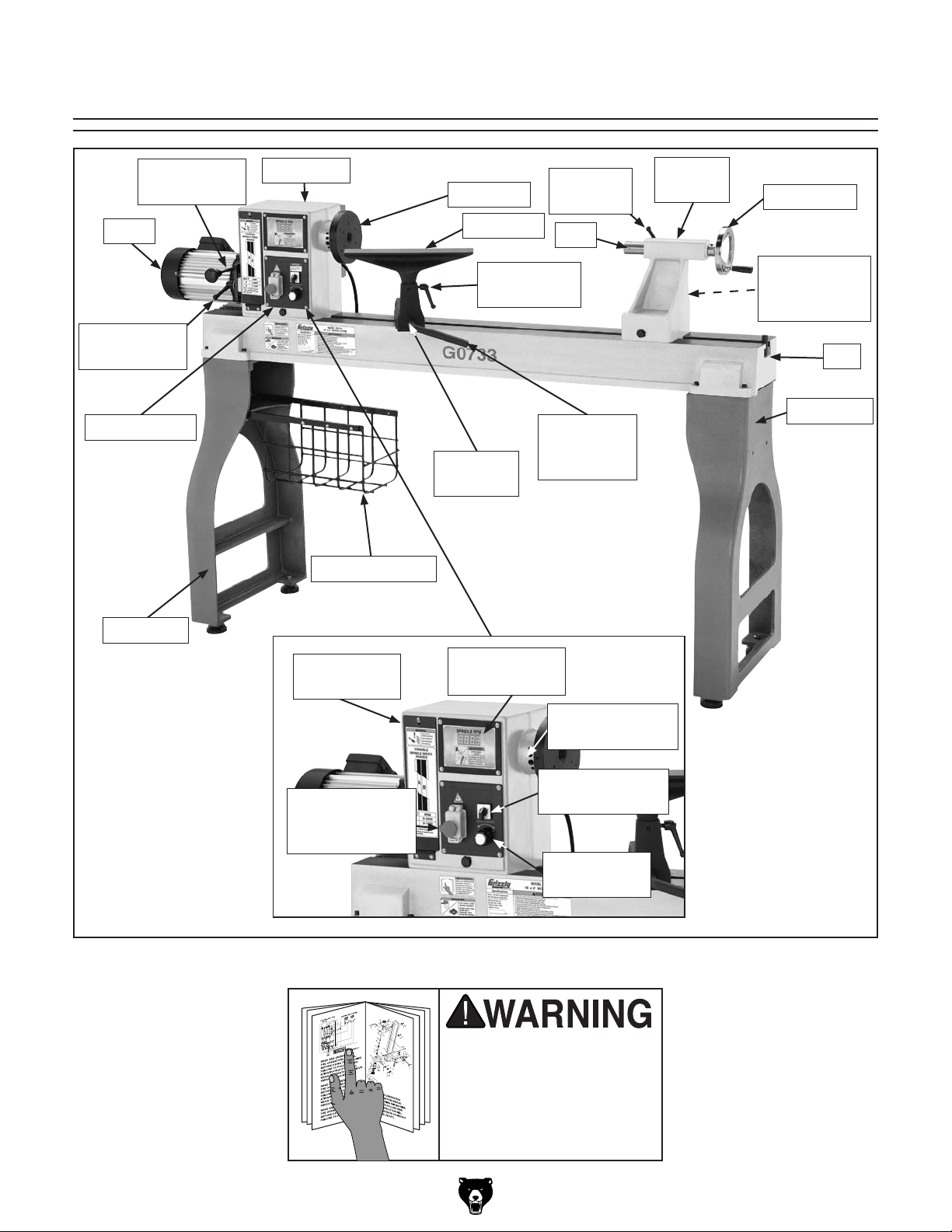
Identification
Belt Tension
Lever
Motor
Belt Tension
Lock Lever
Control Panel
Headstock
Storage Basket
Faceplate
Tool Rest
Tool Rest
Lock Handle
Tool Rest
Base
Quill Lock
Lever
Quill
Tool Rest
Base
Lock Lever
Tailstock
Casting
Handwheel
Tailstock
Lock Lever
(reverse side)
Bed
Stand Leg
Stand Leg
Belt Access
Cover
ON/OFF Switch
w/Emergency
STOP Button
Figure 1. Model G0733 parts and component identification.
Spindle RPM
Readout
Spindle
Indexing Holes
Spindle
Direction Switch
Speed
Control Knob
To reduce the risk of
serious injury when using
this machine, read and
understand this entire
manual before beginning
any operations.
Model G0733 (Mfg. Since 10/11)
-3-
Page 6

Glossary Of Terms
The following is a list of common definitions, terms and phrases used throughout this manual as they relate
to this wood lathe and turning in general. Become familiar with these terms for assembling, adjusting or
operating this machine. Your safety is VERY important to us at Grizzly!
Bed: The long, rail-like metal base to which
the tailstock, tool base, and headstock are
attached.
Chuck: A mechanical device that attaches to the
spindle and holds the workpiece.
Faceplate: The metal disc that threads onto the
headstock spindle.
Faceplate Turning: Turning situation in which
the grain of the turning stock is at right angles
to the lathe bed axis.
Backing Block: A sacrificial piece of wood glued
to the base of the workpiece and screwed to
the faceplate. Often used to prevent mounting marks from appearing on the completed
workpiece.
Headstock: The cast metal box to which the
motor is attached and contains the spindle,
bearings, belts, and electrical components for
operating the lathe.
Outboard Turning: Turning of workpiece with
the headstock situated at the far end of the
lathe so the work done is not over the bed of
the lathe.
Roughing Out: Taking stock from square billet to
round blank.
Spindle: This term has two meanings. First, it
refers to the threaded shaft in the headstock
to which the faceplate is attached. Second, it
refers to any work that is spindle-turned.
Spindle-Turning: Work performed where the
grain and length of the workpiece are parallel
to the axis of the bed.
Swing: The capacity of the lathe, measured
by doubling the distance from the bed to the
spindle center.
Tailstock: The metal component at the opposite
end of the bed from the headstock containing a
quill and live or dead centers. It maintains pressure on the spindle-turned workpiece.
Index head: The mechanism that allows the
headstock spindle to be locked at specific
intervals for layout or other auxiliary tasks.
Offset Turning: A turning situation where the cen-
ter of the workpiece is offset at various stages
of the work to produce different shapes.
-4-
Tool Base: The movable metal fixture attached
to the bed upon which the tool rest is fixed.
Tool Rest: The adjustable metal arm upon which
the tool rest during a turning operation.
Way: One of the metal rails that make up the bed
of the lathe.
Model G0733 (Mfg. Since 10/11)
Page 7

Machine Data Sheet
Machine Data Sheet
MACHINE DATA
SHEET
Customer Service #: (570) 546-9663 · To Order Call: (800) 523-4777 · Fax #: (800) 438-5901
MODEL G0733 HEAVY DUTY WOOD LATHE 18" X 47"
Product Dimensions:
Weight.............................................................................................................................................................. 419 lbs.
Width (side-to-side) x Depth (front-to-back) x Height.................................................... 80-3/4 x 19-1/16 x 48-1/16 in.
Footprint (Length x Width)..................................................................................................................... 65-1/2 x 20 in.
Shipping Dimensions:
Type.......................................................................................................................................................... Wood Crate
Content........................................................................................................................................................... Machine
Weight.............................................................................................................................................................. 550 lbs.
Length x Width x Height....................................................................................................................... 22 x 69 x 22 in.
Must Ship Upright................................................................................................................................................... N/A
Electrical:
Power Requirement........................................................................................................... 220V, Single-Phase, 60 Hz
Prewired Voltage.................................................................................................................................................. 220V
Full-Load Current Rating....................................................................................................................................... 5.3A
Minimum Circuit Size.............................................................................................................................................. 15A
Connection Type....................................................................................................................................... Cord & Plug
Power Cord Included.............................................................................................................................................. Yes
Power Cord Length.......................................................................................................................................... 9-1/2 ft.
Power Cord Gauge......................................................................................................................................... 14 AWG
Plug Included.......................................................................................................................................................... Yes
Included Plug Type................................................................................................................................................ 6-15
Switch Type........................................................................................... ON/OFF Push Button Switch w/Safety Cover
Inverter Type............................................................................................................................................ Delta VFD-M
Inverter Size......................................................................................................................................................... 2 HP
Motors:
Main
Type........................................................................................................................................... TEFC Induction
Horsepower................................................................................................................................................ 2 HP
Phase.................................................................................................................................................... 3-Phase
Amps........................................................................................................................................................... 5.3A
Speed.......................................................................................................................................... 0 – 3560 RPM
Power Transfer .................................................................................................................................. Belt Drive
Bearings..................................................................................................... Shielded & Permanently Lubricated
Main Specifications:
Operation Information
Swing Over Bed......................................................................................................................................... 18 in.
Dist Between Centers................................................................................................................................ 47 in.
Swing Over Tool Rest.......................................................................................................................... 13-3/4 in.
Swing Over Tool Rest Base....................................................................................................................... 14 in.
No of Spindle Speeds............................................................................................................................ Variable
Spindle Speed Range.............................................................................................................. 100 – 3200 RPM
Floor to Center Height......................................................................................................................... 44-7/8 in.
Headstock Rotation....................................................................................................................... 0 or 180 deg.
Model G0733 (Mfg. Since 10/11)
-5-
Page 8

Spindle Information
Spindle Taper............................................................................................................................................ MT#2
Spindle Thread Size.............................................................................................................................. 1-1/4 in.
Spindle TPI................................................................................................................................................ 8 TPI
Spindle Thread Direction.................................................................................................................. Right Hand
Spindle Bore......................................................................................................................................... 0.393 in.
Type of Included Spindle Center................................................................................................................. Spur
Indexed Spindle Increments............................................................................................................. 10, 30 deg.
No of Indexes................................................................................................................................................... 4
Tool Rest Information
Tool Rest Width......................................................................................................................................... 14 in.
Tool Rest Post Diameter......................................................................................................................... 25 mm
Tool Rest Post Length......................................................................................................................... 2-3/16 in.
Tool Rest Base Height......................................................................................................................... 2-1/16 in.
Tailstock Information
Tailstock Taper.......................................................................................................................................... MT#2
Type of Included Tailstock Center............................................................................................................... Live
Construction
Bed.......................................................................................................................... Precision-Ground Cast Iron
Frame................................................................................................................................................... Cast Iron
Stand.................................................................................................................................................... Cast Iron
Base..................................................................................................................................................... Cast Iron
Headstock............................................................................................................................................ Cast Iron
Tailstock............................................................................................................................................... Cast Iron
Paint....................................................................................................................................................... Enamel
Other Related Information
Faceplate Size............................................................................................................................................. 6 in.
Other Specifications:
Country Of Origin ............................................................................................................................................... China
Warranty ........................................................................................................................................................... 1 Year
Approximate Assembly & Setup Time .............................................................................................................. 1 Hour
Serial Number Location ........................................................................................................ ID Label on Front of Bed
ISO 9001 Factory .................................................................................................................................................... No
CSA Certified .......................................................................................................................................................... No
Features:
14" wide tool rest (with post size of 2-1/4"H x 1"Ø)
16" swing over tool rest base
Electronic variable speed control with digital spindle speed indicator
Belt drive offers low speed range of 100–1200 RPM and a high speed range of 330–3200 RPM
Headstock can be rotated 180° and positioned anywhere along the bed
Single-phase frequency drive provides three-phase variable speed control without three-phase power
10º indexing using all three indexing holes
30º direct indexing using 1 indexing hole
Tailstock, headstock, and tool rest support have lever action cam locks for quick positioning
Emergency stop switch
Forward/reverse switch
-6-
Model G0733 (Mfg. Since 10/11)
Page 9

SECTION 1: SAFETY
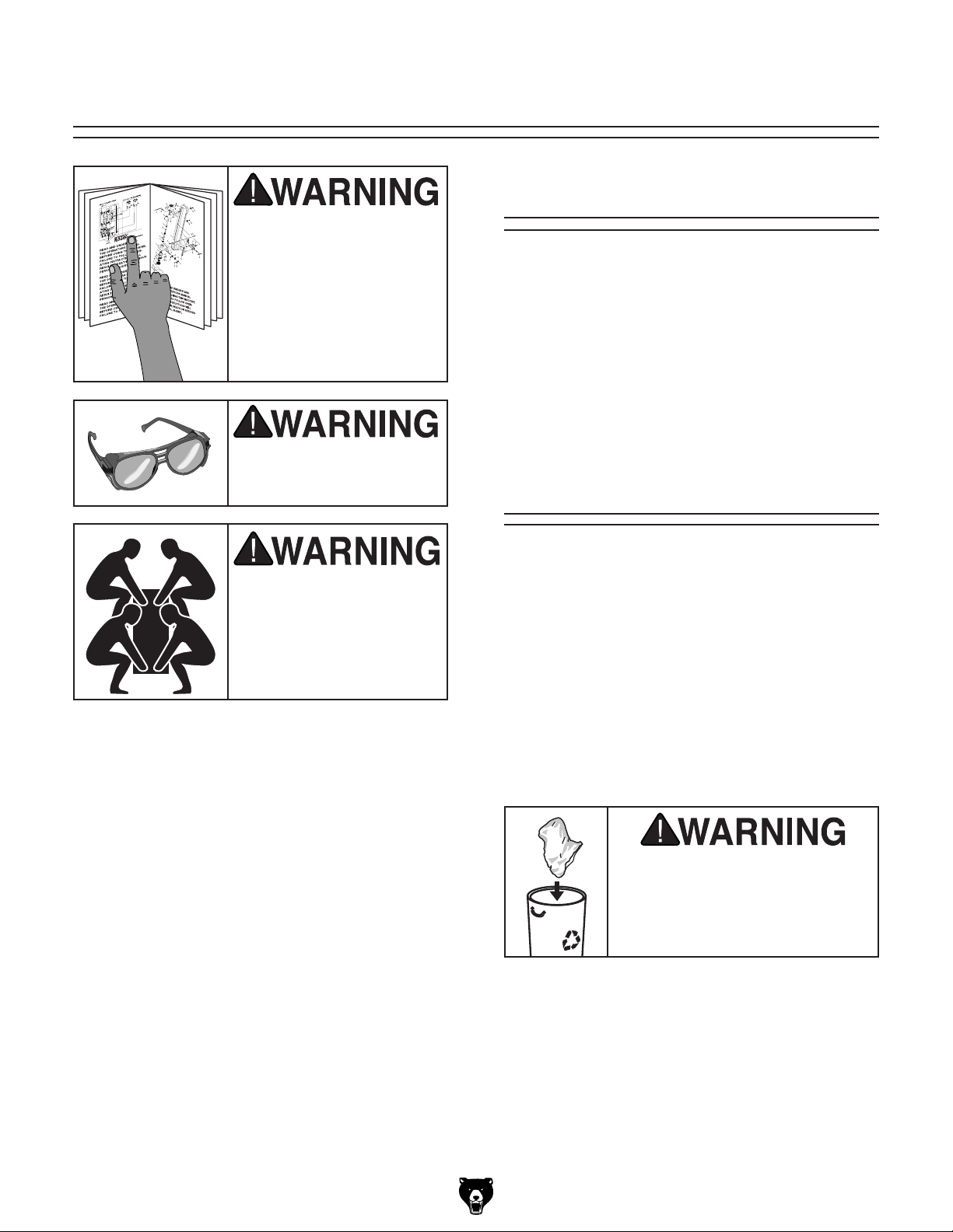
For Your Own Safety, Read Instruction
Manual Before Operating This Machine
The purpose of safety symbols is to attract your attention to possible hazardous conditions.
This manual uses a series of symbols and signal words intended to convey the level of importance of the safety messages. The progression of symbols is described below. Remember that
safety messages by themselves do not eliminate danger and are not a substitute for proper
accident prevention measures. Always use common sense and good judgment.
Indicates an imminently hazardous situation which, if not avoided,
WILL result in death or serious injury.
Indicates a potentially hazardous situation which, if not avoided,
COULD result in death or serious injury.
Indicates a potentially hazardous situation which, if not avoided,
MAY result in minor or moderate injury. It may also be used to alert
against unsafe practices.
This symbol is used to alert the user to useful information about
NOTICE
proper operation of the machine.
Safety Instructions for Machinery
OWNER’S MANUAL. Read and understand this
owner’s manual BEFORE using machine.
TRAINED OPERATORS ONLY. Untrained operators have a higher risk of being hurt or killed.
Only allow trained/supervised people to use this
machine. When machine is not being used, disconnect power, remove switch keys, or lock-out
machine to prevent unauthorized use—especially
around children. Make workshop kid proof!
DANGEROUS ENVIRONMENTS. Do not use
machinery in areas that are wet, cluttered, or have
poor lighting. Operating machinery in these areas
greatly increases the risk of accidents and injury.
MENTAL ALERTNESS REQUIRED. Full mental
alertness is required for safe operation of machinery. Never operate under the influence of drugs or
alcohol, when tired, or when distracted.
ELECTRICAL EQUIPMENT INJURY RISKS. You
can be shocked, burned, or killed by touching live
electrical components or improperly grounded
machinery. To reduce this risk, only allow qualified
service personnel to do electrical installation or
repair work, and always disconnect power before
accessing or exposing electrical equipment.
DISCONNECT POWER FIRST.
nect machine from power supply BEFORE making
adjustments, changing tooling, or servicing machine.
This prevents an injury risk from unintended startup
or contact with live electrical components.
EYE PROTECTION. Always wear ANSI-approved
safety glasses or a face shield when operating or
observing machinery to reduce the risk of eye
injury or blindness from flying particles. Everyday
eyeglasses are not approved safety glasses.
Always discon-
Model G0733 (Mfg. Since 10/11)
-7-
Page 10

WEARING PROPER APPAREL. Do not wear
clothing, apparel or jewelry that can become
entangled in moving parts. Always tie back or
coverlong hair. Wearnon-slip footwearto avoid
accidentalslips,whichcouldcause lossofworkpiececontrol.
hAzARdOus dusT. Dust created while using
machinery may cause cancer, birth defects, or
long-term respiratorydamage. Be aware of dust
hazardsassociatedwitheachworkpiecematerial,
andalwayswearaNIOSH-approvedrespiratorto
reduceyourrisk.
hEARING PROTECTION. Always wear hearing protection when operating or observing loud
machinery. Extended exposure to this noise
withouthearing protection can cause permanent
hearingloss.
REMOVE AdJusTING TOOLs. Tools left on
machinery can become dangerous projectiles
uponstartup.Neverleavechuckkeys,wrenches,
or any other tools on machine. Always verify
removalbeforestarting!
INTENdEd usAGE. Only use machine for its
intendedpurposeand nevermakemodifications
not approved by Grizzly. Modifying machine or
using it differently than intended may result in
malfunctionormechanicalfailurethatcanleadto
seriouspersonalinjuryordeath!
AWKWARd POsITIONs. Keep proper footing
andbalanceatalltimeswhenoperatingmachine.
Donotoverreach!Avoidawkwardhandpositions
that make workpiece control difficult or increase
the
riskofaccidentalinjury.
ChILdREN & BYsTANdERs. Keepchildrenand
bystandersatasafedistancefromtheworkarea.
Stopusingmachineiftheybecomeadistraction.
FORCING MAChINERY.Donot forcemachine.
Itwill do the job safer and betterat the rate for
whichitwasdesigned.
NEVER sTANd ON MAChINE. Serious injury
may occur if machine is tipped or if the cutting
toolisunintentionallycontacted.
sTABLE MAChINE. Unexpectedmovementduring operation greatly increases risk of injury or
lossofcontrol.Beforestarting,verifymachineis
stableandmobilebase(ifused)islocked.
usE RECOMMENdEd ACCEssORIEs.Consult
thisowner’smanualorthemanufacturerforrecommended accessories. Using improper accessorieswillincreasetheriskofseriousinjury.
uNATTENdEd OPERATION. To reduce the
risk of accidental injury, turn machine off and
ensure all moving parts completely stop before
walking away. Never leave machine running
whileunattended.
MAINTAIN WITh CARE.Followallmaintenance
instructions and lubrication schedules to keep
machine in good working condition. A machine
that is
leadingtoseriouspersonalinjuryordeath.
ChECK dAMAGEd PARTs. Regularly inspect
machine for any condition that may affect safe
operation.Immediatelyrepairorreplacedamaged
ormis-adjustedpartsbeforeoperatingmachine.
MAINTAIN POWER CORds. When disconnecting cord-connected machines from power, grab
andpulltheplug—NOTthecord.Pullingthecord
may damage the wires inside. Do not handle
cord/plugwithwethands.Avoidcorddamageby
keepingitawayfromheatedsurfaces,hightraffic
areas,harshchemicals,andwet/damplocations.
improperly maintained could malfunction,
GuARds & COVERs.Guardsandcoversreduce
accidental contact with moving parts or flying
debris. Make sure they are properly installed,
undamaged,andworkingcorrectly.
-8-
EXPERIENCING dIFFICuLT IEs. If at any time
youexperiencedifficulties performingtheintendedoperation,stopusingthemachine!Contactour
TechnicalSupportat(570)546-9663.
Model G0733 (Mfg. Since 10/11)
Page 11

Additional Safety for Wood Lathes
KEEPING GUARDS IN PLACE. Make sure all
guards are in place and that the lathe sits on a
flat, stable surface.
EYE/FACE PROTECTION. Airborne wood dust
and debris can be hazardous to the eyes/face
and may cause allergies or long-term respiratory
health problems. Always wear eye protection or a
face shield when operating the lathe.
RESPIRATORY PROTECTION. Always wear a
respirator when using this machine. Wood dust
may cause allergies or long-term respiratory
health problems.
MOUNTING WORKPIECE. Before starting, be
certain the workpiece has been properly imbedded on the headstock and tailstock centers and
that there is adequate clearance for the full rotation.
ADJUSTING TOOL REST. Adjust tool rest to
provide proper support for the turning tool you
will be using. Test tool rest clearance by rotating
workpiece by hand before turning lathe ON.
TURNING SPEED. Select the correct turning
speed for your work, and allow the lathe to gain
full speed before using.
USING SHARP CHISELS. Keep lathe chisels
properly sharpened and held firmly in position
when turning.
OPERATING DAMAGED LATHE. Never operate the lathe with damaged or worn parts.
WORKPIECE CONDITION. Always inspect the
condition of your workpiece. DO NOT turn pieces
with knots, splits, and other potentially dangerous
conditions. Make sure joints of glued-up pieces
have high quality bonds and won't fly apart during
operation.
ADJUSTMENTS/MAINTENANCE. Make sure
your wood lathe is turned OFF, disconnected from
its power source, and all moving parts have come
to a complete stop before starting any inspection,
adjustment, or maintenance procedure.
STOPPING LATHE. DO NOT stop the lathe by
using your hand against the workpiece. Allow the
lathe to stop on its own.
AVOIDING ENTANGLEMENT. Keep long hair
and loose clothing articles such as sleeves, belts,
and jewelry items away from the lathe spindle.
FACEPLATE TURNING. When faceplate turning,
make sure the faceplate is securely attached to
the workpiece and it is properly attached to the
spindle. When faceplate turning, use lathe chisels
on the downward spinning side of the workpiece
only.
SANDING/POLISHING. Remove the tool rest
when performing sanding or polishing operations
on the rotating spindle.
MATERIAL REMOVAL RATE. Attempting to
remove too much material at once may cause
workpiece to fly out of the lathe.
Like all machinery there is potential danger
when operating this machine. Accidents are
frequently caused by lack of familiarity or
failure to pay attention. Use this machine
with respect and caution to lessen the possibility of operator injury. If normal safety
precautions are overlooked or ignored, serious personal injury may occur.
Model G0733 (Mfg. Since 10/11)
No list of safety guidelines can be complete.
Every shop environment is different. Always
consider safety first, as it applies to your
individual working conditions. Use this and
other machinery with caution and respect.
Failure to do so could result in serious personal injury, damage to equipment, or poor
work results.
-9-
Page 12

SECTION 2: POWER SUPPLY
Before installing the machine, consider the availability and proximity of the required power supply
circuit. If an existing circuit does not meet the
requirements for this machine, a new circuit must
be installed. To minimize the risk of electrocution,
fire, or equipment damage, installation work and
electrical wiring must be done by an electrican or
qualified service personnel in accordance with all
applicable codes and standards.
Electrocution, fire, or
equipment damage may
occur if machine is not
correctly grounded and
connected to the power
The full-load current rating is the amperage a
machine draws at 100% of the rated output power.
On machines with multiple motors, this is the
amperage drawn by the largest motor or sum of all
motors and electrical devices that might operate
at one time during normal operations.
The full-load current is not the maximum amount
of amps that the machine will draw. If the machine
is overloaded, it will draw additional amps beyond
the full-load rating.
If the machine is overloaded for a sufficient length
of time, damage, overheating, or fire may result—
especially if connected to an undersized circuit.
To reduce the risk of these hazards, avoid overloading the machine during operation and make
sure it is connected to a power supply circuit that
meets the requirements in the following section.
For your own safety and protection of
Note: The circuit requirements listed in this manual apply to a dedicated circuit—where only one
machine will be running at a time. If this machine
will be connected to a shared circuit where multiple machines will be running at the same time,
consult a qualified electrician to ensure that the
circuit is properly sized for safe operation.
A power supply circuit includes all electrical
equipment between the breaker box or fuse panel
in the building and the machine. The power supply circuit used for this machine must be sized to
safely handle the full-load current drawn from the
machine for an extended period of time. (If this
machine is connected to a circuit protected by
fuses, use a time delay fuse marked D.)
This machine is prewired to operate on a 220V
power supply circuit that has a verified ground and
meets the following requirements:
Availability
supply.
Full-Load Current Rating
Circuit Information
property, consult an electrician if you are
unsure about wiring practices or electrical
codes in your area.
Full-Load Current Rating at 220V .. 12 .6 Amps
-10 -
Circuit Requirements for 220V
Nominal Voltage .............................. 220V/240V
Cycle .......................................................... 60 Hz
Phase ........................................... Single-Phase
Power Supply Circuit ......................... 15 Amps
Plug/Receptacle ............................. NEMA 6-15
Model G0733 (Mfg. Since 10/11)
Page 13
Improper connection of the equipment-grounding
wire can result in a risk of electric shock. The
wire with green insulation (with or without yellow
stripes) is the equipment-grounding wire. If repair
or replacement of the power cord or plug is necessary, do not connect the equipment-grounding
wire to a live (current carrying) terminal.
Check with a qualified electrician or service personnel if you do not understand these grounding
requirements, or if you are in doubt about whether
the tool is properly grounded. If you ever notice
that a cord or plug is damaged or worn, disconnect it from power, and immediately replace it with
a new one.
We do not recommend using an extension cord
with this machine.
cord, only use it if absolutely necessary and only
on a temporary basis.
Extension cords cause voltage drop, which may
damage electrical components and shorten motor
life. Voltage drop increases as the extension cord
size gets longer and the gauge size gets smaller
(higher gauge numbers indicate smaller sizes).
Any extension cord used with this machine must
contain a ground wire, match the required plug
and receptacle, and meet the following requirements:
Grounding Requirements
This machine MUST be grounded. In the event
of certain malfunctions or breakdowns, grounding
reduces the risk of electric shock by providing a
path of least resistance for electric current.
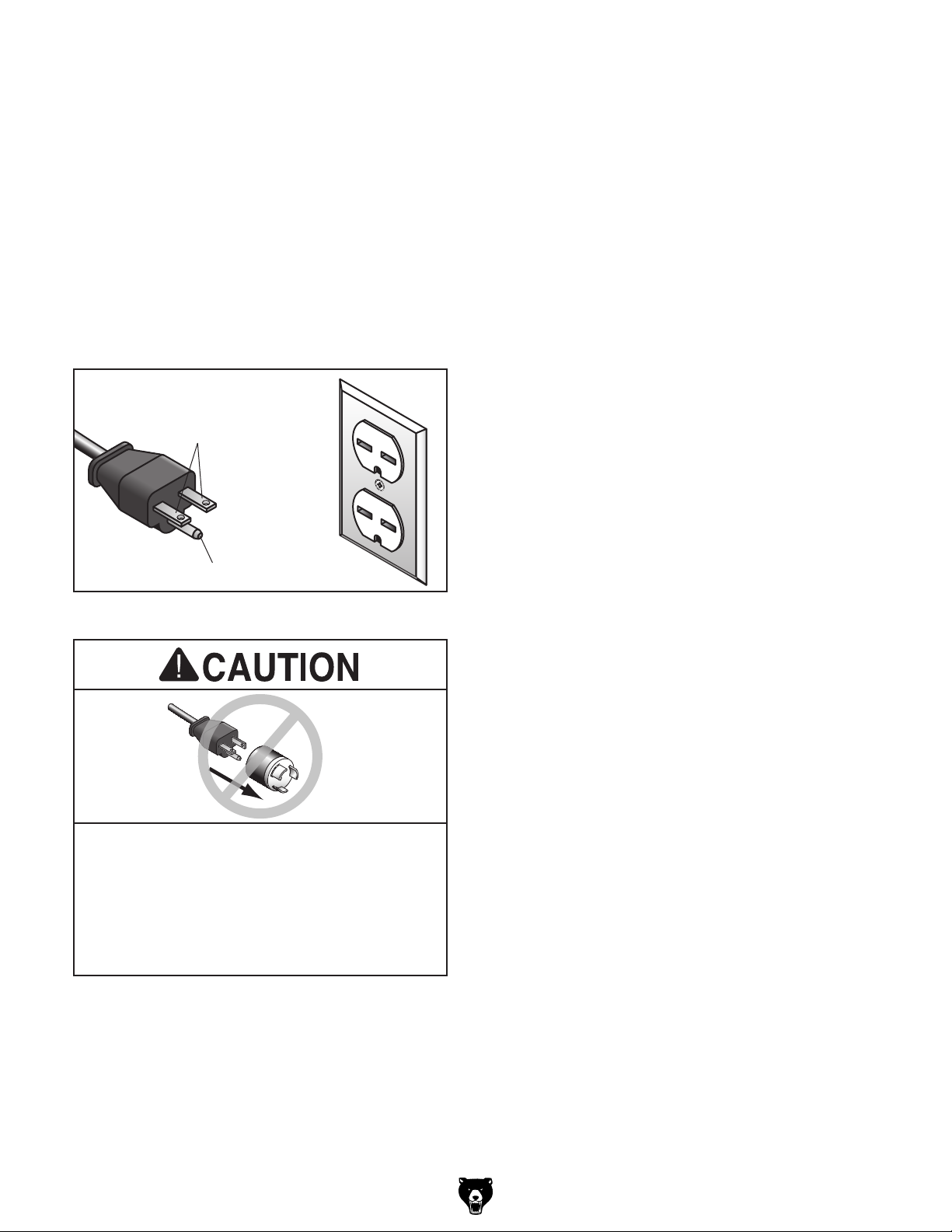
For 220V operation: This machine is equipped
with a power cord that has an equipment-grounding wire and a grounding plug (see following figure). The plug must only be inserted into a matching receptacle (outlet) that is properly installed
and grounded in accordance with all local codes
and ordinances.
No adapter should be used with the
required plug. If the plug does not fit the
available receptacle, or the machine must
GROUNDED
6-15 RECEPTACLE
Current Carrying Prongs
6-15 PLUG
Extension Cords
If you must use an extension
Grounding Prong
Figure 2. Typical 6-15 plug and receptacle.
be reconnected for use on a different type
of circuit, the reconnection must be made
by a qualified electrician and comply with all
local codes and ordinances.
Model G0733 (Mfg. Since 10/11)
Minimum Gauge Size ...........................14 AWG
Maximum Length (Shorter is Better).......50 ft.
-11-
Page 14
SECTION 3: SETUP
Your machine was carefully packaged for safe
transportation. Remove the packaging materials
from around your machine and inspect it. If you
discover any damage, please call us immediately
at (570) 546-9663
Save the containers and all packing materials for
possible inspection by the carrier or its agent.
Otherwise, filing a freight claim can be difficult.
When you are completely satisfied with the condition of your shipment, inventory the contents.
Keep children and pets away
from plastic bags or packing
materials shipped with this
Needed for Setup
This machine presents
serious injury hazards
to untrained users. Read
through this entire manual to become familiar with
the controls and operations before starting the
machine!
Wear safety glasses during the entire setup process!
The following are needed to complete the setup
process, but are not included with your machine.
Description Qty
• Safety Glasses ........................................... 1
• Cleaner/Degreaser ..................... As Needed
• Disposable Shop Rag ................ As Needed
• Additional People ....................... As Needed
• Level ........................................................... 1
Unpacking
The G0733 and its components are very heavy.
Get lifting help or use
power lifting equipment
such as a fork lift to move
heavy items.
for advice.
SUFFOCATION HAZARD!
machine. Discard immediately.
-12-
Model G0733 (Mfg. Since 10/11)
Page 15
Inventory
Inventory
After all the parts have been removed from the
shipping containers, you should have the following items:
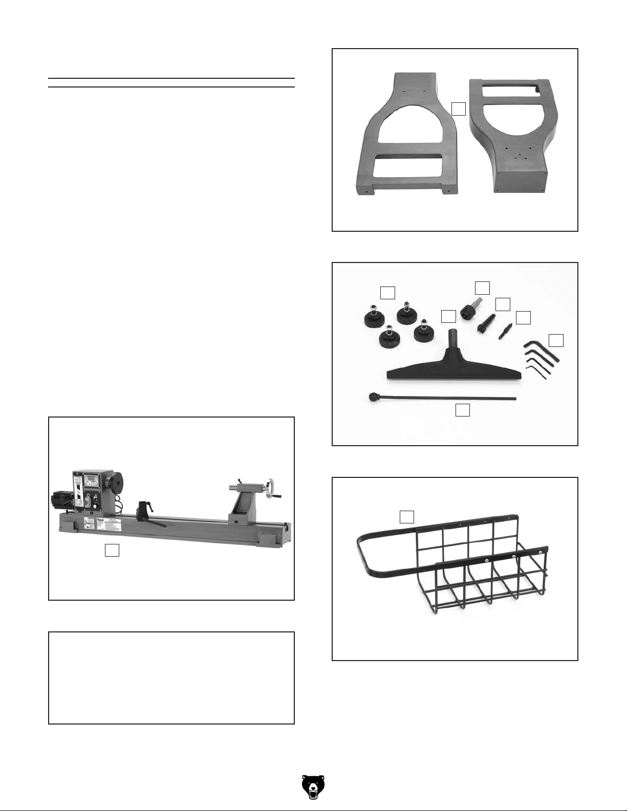
Inventory: (Figures 3–6) Qty
A. Lathe Assembly
—Headstock (mounted) ............................. 1
—Tool Rest Base (mounted) ...................... 1
—Tailstock (mounted) ................................. 1
—Faceplate 6" (installed) ........................... 1
B. Stand Legs ................................................. 2
C. Machine Feet .............................................. 4
D. Tool Re st .................................................... 1
E. Live Center MT#2 ....................................... 1
F. Spur Center MT#2 ...................................... 1
G. Indexing Pin ................................................ 1
H. Hex Wrenches 3, 4, 6, 8mm ..................1 Ea
I. Knockout Tool ............................................. 1
J. Storage Basket ........................................... 1
K. Hardware (not shown)
—Cap Screws M8-1.25 x 35 .................... 10
—Lock Washers 8mm .............................. 10
—Hex Nuts M8-1.25 ................................... 2
B
Figure 4. Stand legs.
C
D
I
E
F
G
H
A
Figure 3. Lathe assembly.
NOTICE
Some hardware/fasteners on the inventory
list may arrive pre-installed. Check mounting locations before assuming that any
items from the inventory list are missing.
Figure 5. Loose inventory components.
J
Figure 6. Storage basket.
If any nonproprietary parts are missing (e.g. a
nut or a washer), we will gladly replace them; or
for the sake of expediency, replacements can be
obtained at your local hardware store.
Model G0733 (Mfg. Since 10/11)
-13-
Page 16
Site Considerations
Weight Load
Physical Environment
Place this machine near an existing power source.
Shadows, glare, or strobe effects that may distract
Refer to the Machine Data Sheet for the weight
of your machine. Make sure that the surface upon
which the machine is placed will bear the weight
of the machine, additional equipment that may be
installed on the machine, and the heaviest workpiece that will be used. Additionally, consider the
weight of the operator and any dynamic loading
that may occur when operating the machine.
Space Allocation
Consider the largest size of workpiece that will
be processed through this machine and provide
enough space around the machine for adequate
operator material handling or the installation of
auxiliary equipment. With permanent installations,
leave enough space around the machine to open
or remove doors/covers as required by the maintenance and service described in this manual.
See below for required space allocation.
Children or untrained people
may be seriously injured by
this machine. Only install in an
access restricted location.
The physical environment where the machine is
operated is important for safe operation and longevity of machine components. For best results,
operate this machine in a dry environment that is
free from excessive moisture, hazardous chemicals, airborne abrasives, or extreme conditions.
Extreme conditions for this type of machinery are
generally those where the ambient temperature
range exceeds 41°–104°F; the relative humidity
range exceeds 20–95% (non-condensing); or the
environment is subject to vibration, shocks, or
bumps.
Electrical Installation
Make sure all power cords are protected from
traffic, material handling, moisture, chemicals,
or other hazards. Make sure to leave access to
a means of disconnecting the power source or
engaging a lockout/tagout device, if required.
Lighting
Lighting around the machine must be adequate
enough that operations can be performed safely.
or impede the operator must be eliminated.
-14-
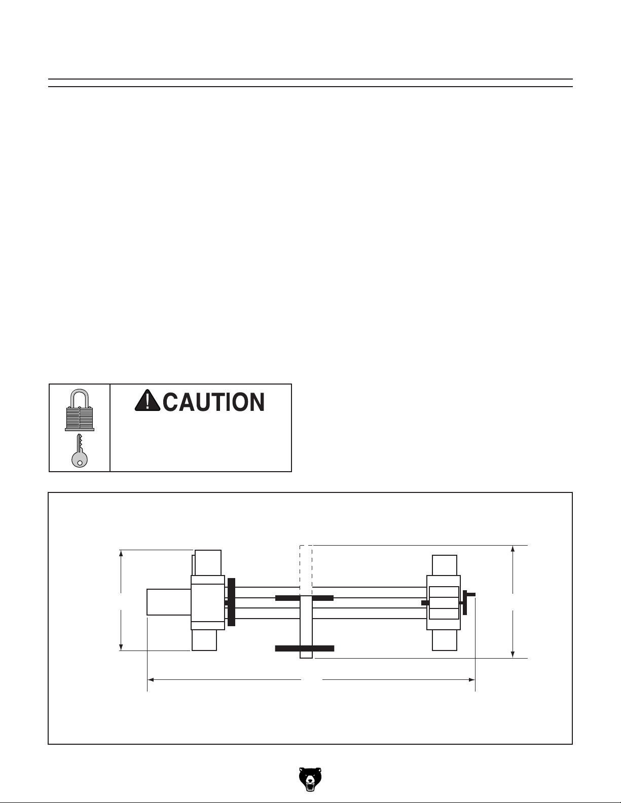
19 1⁄2"
81"
Figure 7. Minimum working clearances.
23 1⁄2"
Model G0733 (Mfg. Since 10/11)
Page 17

Cleanup
The unpainted surfaces of your machine are
coated with a heavy-duty rust preventative that
prevents corrosion during shipment and storage.
This rust preventative works extremely well, but it
will take a little time to clean.
Be patient and do a thorough job cleaning your
machine. The time you spend doing this now will
give you a better appreciation for the proper care
of your machine's unpainted surfaces.
There are many ways to remove this rust preven
tative, but the following steps work well in a wide
variety of situations. Always follow the manufac
turer’s instructions with any cleaning product you
use and make sure you work in a well-ventilated
area to minimize exposure to toxic fumes.
Before cleaning, gather the following:
•
•
•
•
Basic steps for removing rust preventative:
1.
2.
amount of cleaner/degreaser, then let it soak
3. Wipe off the surfaces. If your cleaner/degreas
scrape off as much as you can first, then wipe
4.
then coat all unpainted surfaces with a quality
Avoid chlorine-based solvents, such as
Disposable Rags
Cleaner/degreaser (WD•40 works well)
Safety glasses & disposable gloves
Plastic paint scraper (optional)
Mounting
Although not required, we recommend that you
mount your new machine to the floor. Because
this is an optional step and floor materials may
vary, floor mounting hardware is not included.
Generally, you can either bolt your machine to
the floor or mount it on machine mounts. Both
options are described below. Whichever option
you choose, we recommend leveling your machine
with a precision level.
-
-
Bolting to Concrete Floors
Lag shield anchors with lag screw and anchor
studs, as shown in Figure 8, are two popular
methods for anchoring an object to a concrete
floor. We suggest you research the many options
and methods for mounting your machine and
choose the best that fits your specific application.
Anchor Studs
Put on safety glasses.
Coat the rust preventative with a liberal
for 5–10 minutes.
er is effective, the rust preventative will wipe
off easily. If you have a plastic paint scraper,
off the rest with the rag.
Repeat Steps 2–3 as necessary until clean,
metal protectant to prevent rust.
NOTICE
acetone or brake parts cleaner, that may
damage painted surfaces.
Lag Shield Anchor
and Lag Screw
-
Figure 8. Typical fasteners for mounting to
concrete floors.
NOTICE
Anchor studs are stronger and more permanent alternatives to lag shield anchors;
however, they will stick out of the floor,
which may cause a tripping hazard if you
decide to move your machine.
Model G0733 (Mfg. Since 10/11)
-15-
Page 18

Assembly
The G0733 and its components are very heavy.
Get lifting help or use
power lifting equipment
such as a forklift to move
heavy items.
To assemble your lathe:
4. If bolting the lathe to the floor, skip to
Step 7. Otherwise, move the tailstock, tool
rest assembly, and headstock to one end of
the lathe bed (refer to OPERATIONS section,
beginning on Page 19, for instructions for
moving these components).
5. Use assistants to lift one end of the lathe
onto support blocks and stabilize the lathe
in preparation for installing the machine feet
(see Figure 11).
1. Position the right and left stand legs upright
approximately 57
reasonably aligned (see Figure 9).
Figure 9. Supporting legs.
2. Carefully position the lathe onto the stands
and align the mounting holes.
3. Secure the lathe assembly to the stand legs
with (8) M8-1.25 x 35 cap screws and 8mm
lock washers, as shown in Figure 10.
3
⁄4" apart, and get them
57 3⁄4"
Support Block
Figure 11. Legs supported for feet installation.
6. Remove the top hex nut from the feet, then
insert the feet into the mounting holes of the
leg (see Figure 12). Do not tighten the hex
nuts yet. Remove the supporting block and
repeat Steps 5–6 on the other leg.
-16 -
x 8
Figure 12. Machine feet installed.
Figure 10. Securing lathe assembly.
Model G0733 (Mfg. Since 10/11)
Page 19

7. Place the level on the lathe bed and make
After you have completed all previous setup
instructions and circuit requirements, the machine
is ready to be connected to the power supply.
To avoid unexpected startups or property damage, use the following steps whenever connecting
or disconnecting the machine.
1. TurnthemachinepowerswitchOFF.
2.
matching
is
1. TurnthemachinepowerswitchOFF.
2.
completely
cord
necessary adjustments so that the bed is
level from side-to-side and front-to-back.
—If you are using the machine feet, adjust
the top and bottom hex nuts on each leg to
level the bed; then tighten the hex nuts to
secure these adjustments.
—If you are bolting your lathe to the floor, use
shims under the legs to level the bed; then
tighten the mounting fasteners.
8. Insert the tool rest into the tool rest base and
tighten the tool rest lock handle, as shown in
Figure 13.
Power Connection
Connecting Power
Insert the power cord plug into a
power supply receptacle. The machine
nowconnectedtothepowersource.
Tool Rest
Tool Rest Base
Figure 13. Tool rest installed on the tool rest
9. Attach the storage basket to the leg using
the remaining (2) M8-1.25 x 35 cap screws,
(2) 8mm lock washers, and (2) M8-1.25 hex
nuts, as shown in Figure 14.
Leg
Lock Handle
base.
Tool Rest
Figure 15. Connecting power.
Disconnecting Power
Graspthemoldedplugandpullit
outofthereceptacle.Donotpullbythe
asthismaydamagethewiresinside.
Basket
Model G0733 (Mfg. Since 10/11)
Figure 14. Attaching basket to leg.
Figure 16. Disconnecting power.
-17-
Page 20

Test Run
Once the assembly is complete, test run your
machine to make sure it runs properly and is
ready for regular operation. The test run consists
of verifying the following: 1) The motor powers up
and runs correctly and 2) the STOP button safety
feature works correctly.
If, during the test run, you cannot easily locate
the source of an unusual noise or vibration, stop
using the machine immediately, then review
Troubleshooting on Page 37.
If you cannot find a remedy, contact our Tech
Support at (570) 546-9663 for assistance.
Before starting the lathe, make sure you
have performed the preceding assembly
and adjustment instructions, and you have
read through the rest of the manual and
are familiar with the various functions and
safety features on this machine. Failure to
follow this warning could result in serious
personal injury or even death!
6. Verify that the machine is operating correctly
by turning the spindle direction switch to the
"R" position, and slowly turn the speed control knob to the right.
—When operating correctly, the machine
runs smoothly with little or no vibration or
rubbing noises.
— Investigate and correct strange or unusual
noises or vibrations before operating the
machine further. Always disconnect the
machine from power when investigating or
correcting potential problems.
7. Turn the speed control knob all the way
counterclockwise.
8. Turn the spindle direction switch to the "L"
position, and slowly turn the speed control
knob to the right.
—When operating correctly, the machine
runs smoothly with little or no vibration or
rubbing noises.
9. Move the spindle direction switch to the "O"
position, and push in the EMERGENCY
STOP button.
To test run your lathe:
1. Make sure you understand the safety instruc-
tions at the beginning of the manual and that
the machine is set up properly.
2. Make sure all tools and objects used during
setup are cleared away from the machine.
3. Connect the machine to the power source.
4. Set the spindle direction switch to the neutral
or "O" position and turn the speed control
knob all the way counterclockwise.
5. Squeeze the tab on the side of the
EMERGENCY STOP button in, lift the button
to open the switch cover, and press the green
ON button to start the machine.
10. WITHOUT opening the EMERGENCY STOP
button, turn the spindle direction switch to the
"R" and "L" positions. The machine should
not start at either position.
—If the machine does not start, the
EMERGENCY stop button safety feature
is working correctly. The Test Run is complete.
—If the machine does start (with the
EMERGENCY stop button pushed in),
immediately disconnect power to the
machine. The EMERGENCY stop button
safety feature is not working correctly. This
safety feature must work properly before
proceeding with regular operations. Call
Tech Support for help.
-18-
Model G0733 (Mfg. Since 10/11)
Page 21

Operations
The purpose of this overview is to provide the novice machine operator with a basic understanding
of how the machine is used during operation, so
the
discussed later
in this manual
Due to the generic nature of this overview, it is
not
more about specific operations,
manual and
rienced
research outside of this manual by reading "howto" books, trade magazines, or websites.
SECTION 4: OPERATIONS
Operation Overview
To reduce the risk of
serious injury when using
this machine, read and
understand this entire
manual before beginning
any operations.
machine controls/components
are easier to understand.
Damage to your eyes and lungs could result
from using this machine without proper protective gear. Always wear a face shield and
respirator when operating this machine.
Loose hair, clothing, or
jewelry could get caught
in machinery and cause
serious personal injury.
Keep these items away
from moving parts at all
times to reduce this risk.
NOTICE
If you have never used this type of machine
or equipment before, WE STRONGLY
RECOMMEND that you read books, review
industry trade magazines, or get formal
training before beginning any projects.
Regardless of the content in this section,
Grizzly Industrial will not be held liable for
accidents caused by lack of training.
intended to be an instructional guide. To learn
read this entire
seek additional training from expe
machine operators, and do additional
To complete a typical operation, the operator
does the following:
1. Examines the workpiece to make sure it is
suitable for turning. No extreme bows, knots,
or cracks should exist.
2. Prepares and trims up the workpiece with a
bandsaw or table saw to make it roughly concentric.
3. Installs the workpiece between centers, or
attaches it to a faceplate or chuck.
1
4. Adjusts the tool rest to
centerline, and sets the minimum clearance
between the workpiece and the lip of the tool
rest to
5. Rotates the workpiece by hand to verify
that the spindle and workpiece rotate freely
throughout the full range of motion.
6. Positions any dust collection hoods near the
workpiece to collect wood chips and secures
it in place.
1
⁄4" gap.
⁄8" above the workpiece
Model G0733 (Mfg. Since 10/11)
-19 -
Page 22

7. Verifies the pulley ratio is set for the appropriate speed range for the operation, type of
wood, and size of workpiece installed.
Basic Controls
8. Verifies the spindle direction switch is in the
"O" position and the spindle speed dial is
turned all the way counterclockwise so the
spindle does not start turning at high speed.
9. Ties back loose hair and clothing, and puts
on face shield and respirator. Takes all other
required safety precautions.
10. Starts the lathe and dust collector, adjusts the
spindle direction and lathe speed, and carefully begins the turning operation, keeping the
chisel against the tool rest the entire time it is
cutting.
Refer to Figure 17 and the list below to familiarize yourself with the lathe controls. You will
find that understanding the names and descriptions of the controls is useful when reading this
OPERATIONS section.
A
B
C
D
Figure 17. Control panel and RPM Readout.
A. Spindle RPM Readout: Indicates the spindle
speed in RPM (rotations per minute).
B. Spindle Direction Switch: Toggles the spin-
dle direction between clockwise or counterclockwise.
C. Speed Control Knob: Adjusts the spindle
speed from low to high within the range governed by the pulley belt position.
D. ON/OFF Switch w/Emergency STOP
Button: Turns the lathe ON and OFF.
-20-
Model G0733 (Mfg. Since 10/11)
Page 23

Stock Inspection &
Requirements
Some workpieces are not safe to turn or may
require modification before they are safe to
turn. Before turning a workpiece, inspect all
workpieces for the following:
Adjusting Headstock
The Model G0733 headstock is equipped with a
cam-action clamping system to secure it to the
lathe bed. When the lever is tightened, a locking
plate lifts up underneath the bed and secures
the tailstock in place. The headstock can be
positioned anywhere along the lathe bed.
• Workpiece Type:
This machine is intended for turning natural
wood products. Never attempt to turn any
composite wood materials, plastics, metal,
stone, or rubber workpieces; turning these
materials can lead to machine damage or
severe injury.
• Foreign Objects:
Nails, staples, dirt, rocks and other foreign
objects are often embedded in wood. While
cutting, these objects can become dislodged
and hit the operator, cause tool grab, or break
the turning tool, which might then fly apart.
Always visually inspect your workpiece for
these items. If they can't be removed, DO
NOT turn the workpiece.
• Large/Loose Knots:
Loose knots can become dislodged during
the turning operation. Large knots can cause
a workpiece to completely break in half
during turning and cause machine damage
and injury. Choose workpieces that do not
have large/loose knots.
• Excessive Warping:
Workpieces with excessive bowing or twist-
ing are unstable and unbalanced. Never turn
these workpieces at high speed, or instability
will be magnified and the workpiece can be
ejected from the lathe causing injury. Only
turn concentric workpieces!
To position the headstock along the length of
the lathe bed:
1. DISCONNECT LATHE FROM POWER!
2. Loosen the headstock lock lever (see
Figure 18).
Headstock Lock
Lever
Figure 18. Headstock lock lever location.
3. Slide the headstock to the desired location on
the bed, and use the headstock lock handle
to secure the headstock in position.
Note: The large clamping hex nut underneath
the headstock will require occasional adjusting to ensure proper clamping pressure of
the headstock to the bed. Turn this hex nut
in small increments to fine tune the clamping
pressure as needed.
Model G0733 (Mfg. Since 10/11)
Always operate the lathe with the headstock
firmly locked to the bed. Otherwise, serious
personal injury may occur as the workpiece
or faceplate could shift during operation or
be ejected from the lathe.
-21-
Page 24

Tool Rest
Adjusting Tailstock
The tailstock adjusts in the same manner as the
headstock.
To position the tailstock along the length of
the bed:
1. Loosen the tailstock lock lever and move the
tailstock to the desired position along the
bed, as shown in Figure 19.
Tailstock Lock
Lever
Adjusting Tool Rest
The tool rest assembly on the Model G0733
has two adjustable components, to provide the
safest and most stable position when operating
the lathe. The tool rest base adjusts in the same
manner as the headstock and tailstock. The tool
rest pivots and may be adjusted vertically in the
tool rest base.
To position the tool rest assembly along the
length of the lathe bed:
1. Loosen the tool rest base lock handle and
move the tool rest assembly to the desired
position on the lathe bed, as shown in
Figure 20.
Tool Rest
Figure 19. Tailstock lock lever location.
2. Re-engage the tailstock lock lever to secure
the tailstock to the bed.
Note: The large clamping hex nut underneath
the tailstock will require occasional adjusting
to ensure proper clamping pressure of the
tailstock to the bed. Turn this hex nut in small
increments to fine tune the clamping pressure as needed.
Always operate the lathe with the tailstock
firmly locked to the bed. Otherwise, serious
personal injury may occur by the tailstock
moving during operation and the workpiece
being ejected at high speed.
Tool Rest
Lock Handle
Tool Rest Base
Lock Lever
Figure 20. Tool rest controls.
2. Re-engage the tool rest base lock lever to
secure the tool rest assembly in position.
Note: The large clamping hex nut underneath
the tool rest base will require occasional
adjusting to ensure proper clamping pressure
of the tool rest assembly to the bed. Turn this
hex nut in small increments to fine tune the
clamping pressure as needed.
-22-
Model G0733 (Mfg. Since 10/11)
Page 25

Always operate the lathe with the tool
rest assembly firmly locked in position.
Otherwise, serious personal injury may
occur by the tool being pulled from the
operator's hands.
To adjust the angle or height of the tool rest:
1. Loosen the tool rest base lock lever and the
tool rest lock handle to adjust the position of
the tool rest.
1
2. Position the tool rest approximately
from the workpiece and approximately
above the workpiece center line, as shown in
Figure 21.
1
Workpiece
⁄4"
⁄4" away
1
⁄8"
Headstock Center
2. Make sure the mating surfaces of the center
and spindle are free of debris and oily substances before inserting the center to ensure
a good fit and reduce runout.
3. Insert the tapered end of the center into
the spindle, and push it in with a quick, firm
motion, as shown in Figure 22.
Figure 22. Installing center into the headstock
spindle.
Distances
1
⁄8"
Tool Rest
Figure 21. Tool rest position relative to
workpiece.
3. Re-tighten the tool rest lock handle and the
tool rest base lock lever to secure the tool
rest in position.
Center Line
Installing/Removing
Headstock Center
4. Make sure the center is securely installed by
attempting to pull it out by hand—a properly
installed center will not pull out easily.
Removing the Headstock Center
1. DISCONNECT LATHE FROM POWER!
2. Hold a clean rag under the spindle or wear a
glove to catch the center when you remove
it.
3. Insert the knockout tool through the outbound
end of the spindle and firmly tap the back of
the center, catching it as it falls, as shown in
Figure 23.
Knockout Tool
The included spur center installs into the headstock spindle with an MT#2 tapered fit.
Installing the Headstock Center
1. DISCONNECT LATHE FROM POWER!
Model G0733 (Mfg. Since 10/11)
Figure 23. Removing the headstock center.
-23-
Page 26

Installing/Removing
Tailstock Center
The included live center installs into the tailstock
quill with an MT#2 tapered fit.
Installing the Tailstock Center
1. On the tailstock, loosen the quill lock handle
and rotate the handwheel until the quill extends
out about 1", as shown in Figure 24.
Tailstock Center
5. Make sure the center of the quill lock handle
is aligned with the quill keyway to ensure that
the tailstock center and quill will not freely
rotate under load (see Figure 25).
Quill Lock Handle
Quill
Handwheel
Figure 24. Installing center into tailstock quill.
2. Make sure the mating surfaces of the center
and quill are free of debris and oily substances before inserting the center to ensure
a good fit reduce runout.
3. Firmly insert the tapered end of the center into
the tailstock quill, as shown in Figure 24.
4. Make sure the center is securely installed by
attempting to pull it out by hand—a properly
installed center will not pull out by hand.
Quill Lock Handle
Quill Keyway
Figure 25. Quill lock handle aligned with quill
keyway.
6. Secure the quill in place by re-tightening the
quill lock handle.
Removing the Headstock Center
1. Loosen the quill lock handle.
2. Hold a clean rag under the spindle or wear a
glove to catch the center when you remove
it.
3. Rotate the handwheel counterclockwise—the
tailstock quill will retract back into the quill,
causing the center to be forced out of the
quill.
The tailstock quill must always be locked in
place during lathe operation. Before tightening the quill lock handle, it must be properly
aligned with the quill keyway. Otherwise,
the workpiece can be thrown from the lathe
causing serious personal injury or death.
-24-
Model G0733 (Mfg. Since 10/11)
Page 27

Headstock Faceplate
Changing Speed Ranges
Installing Faceplate
To install the faceplate:
1. DISCONNECT LATHE FROM POWER!
2. Insert the indexing pin into one of the index-
ing holes and rotate the spindle until the pin
engages to prevent the spindle from turning
while you tighten the faceplate, as shown in
Figure 26.
Faceplate Set
Screw (1 of 2)
Figure 26. Locking spindle with indexing pin and
faceplate set screw location.
3. Thread the faceplate onto the spindle until it
is snug.
Changing Speed
Ranges
The Model G0733 has pulley belt configuration
provided two speed ranges (see Figure 27).
Spindle
A = High Range
330-3200 RPM
= Low Range
B
100-1200 RPM
Motor
Figure 27. Speed range belt positions.
Note: To maximize spindle torque, use the low
spindle speed range for spindle speeds of 1200
RPM or less.
Refer to the speed recommendations chart in
Figure 28 to choose the appropriate RPM for your
operation. Then choose the speed range that will
include the selected RPM.
A
B
4. Using the included 4mm hex wrench, tighten
the two set screws along the inside diameter
of the faceplate to secure it to the spindle
(see Figure 26).
To prevent the faceplate and workpiece separating from the spindle during operation,
the headstock faceplate MUST be firmly
threaded onto the spindle and secured in
place by fully tightening the two faceplate
set screws. If these instructions are not
properly performed, serious personal injury
could occur.
Note: To remove the faceplate, disconnect the
lathe from the power source and perform the
steps above in reverse.
Diameter
of Work-
piece
Under 2" 1520 3200 3200
2–4" 760 1600 2480
4–6" 510 1080 1650
6–8" 380 810 1240
8–10" 300 650 1000
10–12" 255 540 830
12–14" 220 460 710
14–16" 190 400 620
To change speed ranges:
1. DISCONNECT LATHE FROM POWER!
Roughing
RPM
Figure 28. Model G0733 speed
recommendations.
General
Cutting
RPM
Finishing
RPM
Model G0733 (Mfg. Since 10/11)
-25-
Page 28

Always choose the correct spindle speed
for an operation. Using the wrong speed
may lead to the workpiece being thrown at
high speed, causing fatal or severe impact
injuries.
2. Open the front belt access panel, as shown in
Figure 29.
Figure 29. Belt access panel removed.
3. Loosen the belt tension lock handle
(Figure 30).
Belt Tensioning
Handle
5. Reach into the belt access cavity and roll the
belt onto the desired set of pulleys, as shown
in Figure 31.
Spindle
A = High Range
330-3200 RPM
= Low Range
B
100-1200 RPM
Motor
A
B
Figure 31. Speed range belt positions.
6. Loosen the belt tension lock handle and
lower the motor.
7. Apply downward pressure on the belt tensioning handle to properly tension the drive belt,
then re-tighten the belt tension lock handle.
Note: When properly tensioned, the belt
1
should deflect about
⁄8" when moderate pressure is applied to the belt mid-way between
the upper and lower pulley, as shown in
Figure 32.
Belt Tension
Lock Handle
Figure 30. Motor tensioning handle and tension
lock handle.
4. Use the belt tensioning handle (Figure 30) to
lift the motor assembly all the way up, then
re-tighten the belt tension lock handle—this
will hold the motor in place while you change
the belt position.
-26-
Pulley
Deflection
Pulley
1
Figure 32. Testing for
⁄8" belt deflection.
8. Replace the front belt access panel.
Model G0733 (Mfg. Since 10/11)
Page 29

Spindle Turning
Indexing
Indexing on a lathe is typically used for workpiece
layout and other auxiliary operations that require
equal distances around the workpiece circumference, such as clock faces or inlays.
By inserting the indexing pin into one of the four
outer indexes of the Model G0733 spindle housing
and engaging one of the 12 inner indexes in the
spindle, the workpiece can be positioned in 10°
increments, as shown in Figures 33–34.
Indexing
Pin
4
Outer
Indexes
12
Inner
Indexes
Spindle Turning
Spindle turning is the operation performed when
a workpiece is mounted between the headstock
and the tailstock, as shown in Figure 35.
Figure 35. Typical spindle turning operation.
Spindle
Figure 33. Model G0733 indexing configuration.
Figure 34. Indexing pin and indexing holes.
Always disconnect the lathe from power
before using the indexing feature. DO NOT
start the lathe with the indexing pin inserted
into the spindle; otherwise entanglement
injury and property damage could occur.
Faceplate
Damage to your eyes and lungs could result
from using this machine without proper protective gear. Always wear a face shield and
respirator when operating this machine.
To set up a spindle turning operation:
1. Find the center point of both ends of your
workpiece by drawing diagonal lines from
corner to corner across the end of the
workpiece, as shown in Figure 36.
Workpiece
Pencil Lines
Marked Diagonally
Across Corners
Workpiece
Center
Figure 36. Workpiece marked diagonally from
corner to corner to determine the center.
Model G0733 (Mfg. Since 10/11)
-27-
Page 30

2. Make a center mark by using a wood mallet
and tapping the point of the spur center into
the center of the workpiece on both ends.
1
3. Using a
⁄4" drill bit, drill a 1⁄4" deep hole at the
center mark on the end of the workpiece to
be mounted on the headstock spur center.
4. To help embed the spur center into the
1
workpiece, cut
⁄8" deep saw kerfs in the
headstock end of the workpiece along the
diagonal lines marked in Step 1.
5. If your workpiece is over 2" x 2", cut the corners off the workpiece lengthwise to make
turning safer and easier (see Figure 37).
Workpiece
Center
7. With the workpiece still attached, insert the
spur center into the headstock spindle (refer
to Installing/Removing Headstock Center
on Page 23 for additional instructions).
Note: Use the tool rest to support the opposite
end of the workpiece so that the workpiece
and spur center do not separate during
installation.
8. Install the live center into the tailstock quill
and tighten the quill lock handle to lock the
quill in position (refer to Page 24 for additional instructions).
9. Slide the tailstock toward the workpiece
until the point of the live center touches the
workpiece center mark, then lock the tailstock
in this position.
10. Loosen the quill lock handle and rotate the
tailstock handwheel to push the live center
1
into the workpiece at least a
⁄4".
Figure 37. Corners of workpiece removed.
6. Drive the spur center into the end center
mark of the workpiece with a wood mallet to
1
embed it at least
⁄4" into the workpiece, as
shown in Figure 38.
1/4"
Figure 38. Spur center properly embedded.
Do not press the workpiece too firmly with
the tailstock or the bearings will bind and
overheat. Do not adjust the tailstock too
loosely or the workpiece will spin off the
lathe. Use good judgment and care, otherwise, serious personal injury could result
from the workpiece being ejected at high
speeds.
11. Properly adjust the tool rest to the workpiece
(see Adjusting Tool Rest on Page 23).
12. Before beginning lathe operation, rotate the
workpiece by hand to ensure that there is
safe clearance on all sides.
Keep the lathe tool resting on the tool
rest the ENTIRE time that it is in contact
with workpiece or when preparing to make
contact between lathe tool and workpiece.
Otherwise, the spinning workpiece could
force the lathe tool out of your hands or
entangle your hands with the workpiece.
Failure to heed this warning could result in
serious personal injury.
-28-
Model G0733 (Mfg. Since 10/11)
Page 31

Spindle Turning Tips:
• When turning the lathe ON, stand away from
the path of the spinning workpiece until the
spindle reaches full speed and you can verify
that the workpiece will not come loose.
• Use the slowest speed when starting or stopping the lathe.
• Select the right speed for the size of workpiece
that you are turning (refer to Figure 28 on
Page 25).
• Keep the turning tool on the tool rest the
ENTIRE time that it is in contact with the
workpiece.
• Learn the correct techniques for each tool
you will use. If you are unsure about how to
use the lathe tools, read books or magazines
about lathe techniques, and seek training
from experienced and knowledgeable lathe
users.
Faceplate Turning
Faceplate Turning
Faceplate turning is when a workpiece is mounted
to the faceplate, which is then mounted to the
headstock spindle, as shown in Figure 39. This
type of turning is usually done with open-faced
workpieces like bowls or plates.
Figure 39. Typical faceplate turning operation.
Damage to your eyes and lungs could result
from using this machine without proper protective gear. Always wear a face shield and
respirator when operating this machine.
Mounting the Workpiece onto the
Faceplate
1. Mark the workpiece center in the same man-
ner as described in Spindle Turning (see
Page 27).
Note: Cut off corners of the workpiece to make
it as close to "round" as possible as described
in Spindle Turning (see Page 27).
2. Center the faceplate on the workpiece and
attach it, as shown in Figure 40, with wood
screws that do not have tapered heads (see
Figure 41).
Model G0733 (Mfg. Since 10/11)
-29-
Page 32

Figure 40. Typical attachment of faceplate to
workpiece.
NOTICE
Only use screws with non-tapered heads
(see Figure 41) to attach the faceplate to
the workpiece. Screws with tapered heads
can split the faceplate or snap off during
operation.
Correct Incorrect
Mounting Workpiece to Backing
Block
1. Make the backing block from a suitable size
piece of scrap wood.
Note: The faces of the backing block must be
flat and parallel to each other, or the uneven
surfaces will cause the workpiece to spin
eccentricly, causing unnecessary vibration
and runout. It is best to mount the backing
block to the faceplate and turn the other surface flat prior to mounting.
2. Locate and mark the center of both the
workpiece and backing block.
1
3. Drill a
backing block.
4. Look through the hole in the backing block
to line up the center with the workpiece and
glue and clamp the backing block to the
workpiece.
Note: Allow the glue to cure according to the
manufacturer's instructions.
⁄4" hole through the center of the
Figure 41. Correct and incorrect screw types.
3. Thread and secure the faceplate onto the
headstock spindle (refer to Headstock
Faceplate on Page 25 for faceplate mount-
ing instructions).
— If wood screws cannot be placed in the
workpiece, the faceplate can be mounted to a backing block attached to the
workpiece (see Mounting the Workpiece
to a Backing Block).
-30-
5. Follow Steps 1–3 under Mounting the
Workpiece onto the Faceplate (see Page
33) to attach the backing block to the face-
plate.
Outboard Turning
Outboard turning is a variation of faceplate turning
and is accomplished with the headstock positioned
so the faceplate is not directly over the bed, allowing a larger turning capacity than the swing specification of the lathe. On the G0733, the maximum
workpiece diameter that can safely be outboardturned is limited to 17".
The only way to rotate the headstock on this
machine is to remove it from the bed first, which
can be a heavy and cumbersome task. A much
simpler alternative to removing the headstock
is to simply remove the tailstock and slide the
headstock to the other end of the bed. This will
position the spindle so it is not directly over the
bed whereby outboard turning can safely be
accomplished.
Model G0733 (Mfg. Since 10/11)
Page 33

To outboard turn on the Model G0733:
1. DISCONNECT LATHE FROM POWER!
Sanding/Finishing
2. Remove the tailstock and tool base from the
machine by removing the hex nuts and clamp
washers located underneath the assemblies,
then lifting them from the lathe bed.
3. Loosen the headstock, then move it all the
way to the tail end of the lathe bed, as shown
in Figure 42.
Figure 42. Lathe prepared for outboard turning.
4. Re-tighten the headstock to the bed.
After the turning operations are complete,
the workpiece can be sanded and finished
before removing it from the lathe, as shown in
Figure 43.
Figure 43. Typical sanding operation.
Note: Whenever sanding or finishing, move the
tool rest holder out of the way to increase personal safety and gain adequate working room.
When outboard turning, ALWAYS use a floor
mounted tool rest and keep the tool in contact with the rest during all turning operations. Failure to do so could cause the tool
to be pulled out of the operator's control
and ejected at high speed.
Sandpaper
Workpiece
Wrapping the sandpaper completely around
the workpiece could pull
your hands into the moving workpiece and may
cause serious injury.
Never wrap sandpaper
or finishing materials
completely around the
workpiece.
Model G0733 (Mfg. Since 10/11)
-31-
Page 34

Selecting Turning
Tools
Lathe tools come in a variety of shapes and sizes,
and usually fall into five major categories.
• Gouges—Mainly used for rough cutting,
detail cutting, and cove profiles. The rough
gouge is a hollow, double-ground tool with
a round nose, and the detail gouge is a hollow, double-ground tool with either a round or
pointed nose.
• Scrapers—Typically used where access for
other tools is limited, such as hollowing operations. This is a flat, double-ground tool that
comes in a variety of profiles (round nose,
spear point, square nose, etc.) to match
many different contours.
Figure 46. Example of a round nose scraper.
• Parting Tools—Used for sizing and cutting off work. This is a flat tool with a sharp
pointed nose that may be single- or doubleground.
Figure 44. Example of a gouge.
• Skew Chisel—A very versatile tool that can
be used for planing, squaring, V-cutting,
beading, and parting off. The skew chisel is
flat, double-ground with one side higher than
the other (usually at an angle of 20°–40°).
Figure 45. Example of a skew chisel.
Figure 47. Example of a parting tool.
• Specialty Tools—These are the unique,
special function tools to aid in hollowing, bowl
making, cutting profiles, etc. The Swan Neck
Hollowing Tool shown on Page 35 is a good
example of a speciality tool.
-32-
Model G0733 (Mfg. Since 10/11)
Page 35

ACCESSORIES
SECTION 5: ACCESSORIES
Some aftermarket accessories can be
installed on this machine that could cause
it to function improperly, increasing the risk
of serious personal injury. To minimize this
risk, only install accessories recommended
for this machine by Grizzly.
NOTICE
Refer to the newest copy of the Grizzly
Catalog for other accessories available for
this machine.
T23311—Shop Fox 5-pc. Lathe Chisel Set
With massive high speed steel blades and long
ash handles, this set includes a 1" roughing
3
gouge,
spindle gouge, and a
⁄8" straight chisel, a hollowing tool, 3⁄8"
1
⁄8" parting tool. Also
includes a fitted aluminum case.
Figure 49. Shop Fox 5-pc. chisel set.
Sovereign Turning System
Sovereign is a new handle and tool system
allowing the turner to customize the tools they
need for the type of turning they do. Sold with or
3
without
⁄8" and 1⁄2 " collet options, plus the gamut
of tool tips will make you wonder how you managed without a Sovereign. All tools are high speed
steel construction for long life and dependable
use. Below are just some of the options available
with this system.
T21644—16" Sovereign System w/ Collets
T21645—22" Sovereign System w/ Collets
3
T21648—Sovereign
T21649 —Sovereign
1
T21654—
T21655—
T21656—
T21660—
⁄4" Bowl Gouge
3
⁄8" Bowl Gouge
1
⁄2" Bowl Gouge
3
⁄4" Bowl Gouge
⁄8" Collets
1
⁄2" Collets
H7940—3-pc. Lathe Scraper Set
This set is ideal for bowl turning and detail work.
Each chisel measures roughly 16" long with 10"
ash handles and high speed steel blades. Set
includes one round, one curved, and one 90°
corner chisel.
Figure 50. 3 pc. scraper set.
Figure 48. Sovereign 16" and 22" handles.
Model G0733 (Mfg. Since 10/11)
-33-
Page 36

G9274—6" Stainless Steel Outside Calipers
G9275—8" Stainless Steel Outside Calipers
G9276 —10" Stainless Steel Outside Calipers
G9277—12" Stainless Steel Outside Calipers
G9278 —16" Stainless Steel Outside Calipers
Spring Calipers with quick adjustment nut provide
fast determination of external measurements.
Ideal for physically transferring dimensions from
originals. Five different sizes allow you to match
the best caliper for your shop needs.
Figure 51. Model G9278 16" Stainless Steel
Calipers.
H5884—8" Pencil Divider
H5885—10" Pencil Divider
H5886—12" Pencil Divider
H5887—16" Pencil Divider
Transfer precise distances for highly accurate
layouts. Bisect angles for precise angle measurements. Steel legs with fine points scribe
most materials. Pencil holder converts dividers
to a compass. Knurled knob locks dividers from
0–90°. Size indicates leg lengths.
T21771—Woodturning: A Foundation Course
Designed to improve your turning, this DVD
provides all of the basic turning techniques and
practices in detailed step-by-step demonstrations
you can follow along with. Topics include suitable
workpiece and tool selection, copy turning, turning between centers of faceplate, sanding and
fine finishing, and maintaining and edge on your
tools.
Figure 53. Model T21771 Woodturning: A
Foundation Course DVD.
T21985—The Missing Shop Manual: Lathe
This manual covers all the things your new lathe
is designed to do. Besides explaining safety and
set-up, this handy reference takes you through
sharpening your tools and faceplate, bowl, and
spindle turning techniques. The techniques needed to maximize your lathe’s capabilities and hone
your skills are covered. 152 pages.
Figure 52. Models H5884–H5887 Pencil
Dividers.
-34-
Figure 54. Model T20381 The Missing Shop
Manual: Lathe book.
Model G0733 (Mfg. Since 10/11)
Page 37

Swan Neck
G5683—Magnetic Base Light
Light up your work just where you need it. This
flexible neck lamp attaches with the twist of a
switch so that you can use on any machine.
Figure 55. Magnetic base light.
H2371—GOOD STUFF Wood Finish 1 Pint
H2372—GOOD STUFF Wood Finish 1 Quart
For bare wood surfaces, this fast drying synthetic
oil has been formulated to enhance the natural
look of wood. Non-toxic, alcohol resistant and
FDA approved for food contact. Sold in 1 pint and
1 quart quantities!
Recommended Metal Protectants
G5562—SLIPIT® 1 Qt. Gel
G5563—SLIPIT
G2871—Boeshield
G2870—Boeshield
H3788—G96
H3789—G96
Figure 58. Recommended products for protect-
ing unpainted cast iron/steel part on machinery.
®
12 oz Spray
®
T-9 12 oz Spray
®
®
Gun Treatment 12 oz Spray
®
Gun Treatment 4.5 oz Spray
T-9 4 oz Spray
Figure 56. GOOD STUFF bare wood finish.
H6267—11⁄4" x 8 TPI Chuck
This 4-Jaw, self-centering chuck with dovetailed
jaws is great for small bowl and plate turning.
The feature jaws that grip by clamping around
the workpiece or expanding to fit a turned recess.
Compact design makes it ideal for small lathes.
T10117—Big Mouth Dust Hood with Stand
Capture dust from any machine operation with
this Big Mouth Dust Hood. Simply attach a 4" dust
collection hose and adjust the hood right where
you need it. The free standing base eliminates
3
complicated machine set-ups and the tilting 16
7
⁄8" hood adjusts from 23" to 43" high. Every
x 12
⁄8"
shop needs one of these!
Figure 59. T10117 Big Mouth Dust Hood.
1
Figure 57. 1
⁄4" x 8 TPI Chuck.
Model G0733 (Mfg. Since 10/11)
-35-
Page 38

SECTION 6: MAINTENANCE
Always disconnect power
to the machine before
performing maintenance.
Failure to do this may
result in serious personal injury.
Schedule
For optimum performance from your machine,
follow this maintenance schedule and refer to any
specific instructions given in this section.
Lathe Bed
Protect the unpainted cast iron lathe bed by using
a lightly oiled rag and wiping it clean after every
use—this ensures moisture from wood dust does
not remain on the bare metal surfaces.
Keep your lathe bed rust-free with regular applications of products like G96 Gun Treatment, SLIPIT,
or Boeshield T-9.
Lubrication
Ongoing:
• Loose faceplate or mounting bolts.
• Damaged center or tooling.
• Worn or damaged wires.
• Loose machine components.
• Any other unsafe condition.
Daily:
• Clean off dust buildup.
• Clean and lubricate lathe bed, spindle, and
quill.
Monthly:
• Belt tension, damage, or wear.
• Clean out dust buildup from inside belt/pulley
cavity.
Cleaning
All bearings for the Model G0733 are lubricated
and sealed at the factory, and do not need additional lubrication.
Wipe a lightly oiled shop rag on the outside of the
headstock spindle. DO NOT allow any oil to get on
the inside mating surfaces of the spindle.
Use the tailstock handwheel to extend the quill
out to the furthest position and apply a thin coat
of white grease to the outside of the quill. DO NOT
allow any oil or grease to get on the inside mating
surfaces of the quill.
Cleaning the Model G0733 is relatively easy.
Vacuum excess wood chips and sawdust, and
wipe off the remaining dust with a dry cloth. If any
resin has built up, use a resin dissolving cleaner
to remove it. Treat all unpainted cast iron and
steel with a non-staining lubricant after cleaning.
Remove and debris or oily substances from the
inside of the spindle and quill.
-36-
Model G0733 (Mfg. Since 10/11)
Page 39

SECTION 7: SERVICE
Review the troubleshooting and procedures in this section if a problem develops with your machine. If you
need replacement parts or additional help with a procedure, call our Technical Support at (570) 546-9663.
Note: Please gather the serial number and manufacture date of your machine before calling.
Troubleshooting
Motor & Electrical
Symptom Possible Cause Possible Solution
Machine does not
start or a breaker
trips.
Machine stalls or is
underpowered.
Machine has
vibration or
noisy operation
(without workpiece
installed).
1. Emergency stop push-button is engaged/
faulty.
2. Motor connection wired incorrectly.
3. Spindle direction switch is at fault.
4. Circuit board or control board is at fault.
5. Speed rotary switch is at fault.
6. Wiring is open/has high resistance.
7. Motor is at fault.
8. Frequency inverter is at fault.
1. Machine is undersized for the task.
2. Feed rate/cutting speed too fast for task.
3. Belt slipping.
4. Motor connection is wired incorrectly.
5. Pulley slipping on shaft.
6. Motor bearings are at fault.
7. Motor has overheated.
8. Motor is at fault.
1. Motor or component is loose.
2. Belt worn or loose.
3. Pulley is loose.
4. Machine is incorrectly mounted or sits
unevenly on floor.
5. Motor mount loose/broken.
6. Motor bearings are at fault.
1. Open switch cover and press ON button/replace it.
2. Correct motor wiring connections.
3. Replace faulty spindle direction switch.
4. Replace faulty board.
5. Replace bad speed rotary switch.
6. Check for broken wires or disconnected/corroded
connections, and repair/replace as necessary.
7. Test/repair/replace.
8. Replace.
1. Use sharp lathe bits and chisels; reduce the feed
rate/depth of cut.
2. Decrease feed rate/cutting speed.
3. Replace bad belt and re-tension (see Page 39).
4. Correct motor wiring connections.
5. Replace loose pulley.
6. Test by rotating shaft; rotational grinding/loose shaft
requires bearing replacement.
7. Clean off motor, let cool, and reduce workload.
8. Test/repair/replace.
1. Inspect/replace stripped or damaged bolts/nuts, and
re-tighten with thread locking fluid.
2. Inspect/replace belts (see Page 39).
3. Replace shaft, pulley, setscrew, and key as
required.
4. Tighten/replace anchor studs in floor; relocate/shim
machine; adjust feet.
5. Tighten/replace.
6. Test by rotating shaft; rotational grinding/loose shaft
requires bearing replacement.
Troubleshooting
Model G0733 (Mfg. Since 10/11)
-37-
Page 40

Wood Lathe Operation
Symptom Possible Cause Corrective Action
Vibration noise while
machine is running; noise
changes when speed is
changed.
Excessive vibration (with
workpiece installed).
Chisels grab or dig into
workpiece.
Bad surface finish on
workpiece.
1. Belt cover loose. 1. Tighten the screws that secure the belt cover; if
1. Workpiece mounted incorrectly.
2. Headstock, tailstock, or tool rest not
securely clamped to lathe bed.
3. Workpiece warped, out of round, or
is flawed.
4. Spindle speed is set too fast for
mounted workpiece.
5. Lathe is resting on an uneven surface.
6. Motor mount bolts are loose.
7. Belt is worn or damaged.
8. Spindle bearings are worn.
1. Tool rest set too low.
2. Tool rest set too far from workpiece.
3. Wrong chisel/tool being used.
4. Chisel/tool dull.
1. Wrong spindle speed.
2. Dull chisel or wrong chisel being
used for the operation.
necessary install a soft, vibration dampening material between the belt cover and the headstock casting.
1. Re-mount workpiece, making sure that centers are
embedded in true center of workpiece.
2. Check clamp levers and tighten if necessary.
3. Cut workpiece to correct, or use a different
workpiece.
4. Reduce the spindle speed.
5. Shim stand or adjust feet on stand to remove any
wobbles present in the stand.
6. Tighten motor mount bolts.
7. Replace belt (see Page 39).
8. Replace spindle bearings.
1. Set tool rest higher. See Page 22 for how to properly set the tool rest height.
2. Move the tool rest closer to the workpiece. See
Page 22 for the proper workpiece/tool rest clearance.
3. Use the correct chisel/tool; educate yourself by
reading books, trade magazines, or seeking help
from an experienced lathe operator.
4. Sharpen or replace the chisel/tool you are using.
1. Use trial-and-error to find a better spindle speed.
2. Sharpen chisel or try a different chisel.
Tailstock moves under
load.
Can't remove tapered tool
from tailstock barrel.
1. Tailstock mounting bolt loose.
2. Bed surface is oily or greasy.
1. Tailstock barrel not retracted all the
way back into the tailstock.
2. Debris was not removed from taper
before inserting into barrel.
1. Tighten.
2. Clean bed surface to remove excess oil/grease.
1. Turn the barrel handwheel until it forces taper out of
barrel.
2
. Always make sure that taper surfaces are clean.
-38-
Model G0733 (Mfg. Since 10/11)
Page 41

Changing Belt
To change the belt:
Changing V-Belt
4. Use the belt tensioning handle (Figure 61) to
lift the motor assembly all the way up, then
re-tighten the motor tension lock handle—this
will hold the motor in place while you change
the belt position.
1. DISCONNECT LATHE FROM POWER!
2. Open the front belt access panel, as shown in
Figure 60.
Figure 60. Belt access panel removed.
3. Loosen the belt tension lock handle shown in
Figure 61.
5. Reach into the belt access cavity and roll the
belt off the motor (lower) pulleys, then pull the
belt off the spindle pulleys and out the side of
the headstock.
Note: Removing the plastic cover on the
left side may aid in the belt removal and
installation.
6. Install the new belt by reversing Step 5.
7. Apply downward pressure on the belt tension-
ing handle to properly tension the drive belt,
then re-tighten the belt tension lock handle.
Note: When properly tensioned, the belt
should deflect about
sure is applied to the belt mid-way between
the upper and lower pulley, as illustrated in
Figure 32.
1
⁄8" when moderate pres-
Belt Tensioning
Handle
Belt Tension
Lock Handle
Figure 61. Belt tensioning handle and tension
lock handle.
Pulley
Deflection
Pulley
Figure 62. Testing for 1⁄8" belt deflection.
8. Ensure the belt ribs are fully seated in the
pulley grooves then close the front belt
access panel.
Model G0733 (Mfg. Since 10/11)
-39-
Page 42

SECTION 8: WIRING
These pages are current at the time of printing. However, in the spirit of improvement, we may make changes to the electrical systems of future machines. Study this section carefully. If there are differences between
your machine and what is shown in this section, call Technical Support at (570) 546-9663 for assistance
BEFORE making any changes to the wiring on your machine.
Wiring Safety Instructions
SHOCK HAZARD. Working on wiring that is connected to a power source is extremely dangerous.
Touching electrified parts will result in personal
injury including but not limited to severe burns,
electrocution, or death. Disconnect the power
from the machine before servicing electrical components!
MODIFICATIONS. Modifying the wiring beyond
what is shown in the diagram may lead to unpredictable results, including serious injury or fire.
This includes the installation of unapproved aftermarket parts.
WIRE CONNECTIONS. All connections must
be tight to prevent wires from loosening during
machine operation. Double-check all wires disconnected or connected during any wiring task to
ensure tight connections.
CIRCUIT REQUIREMENTS. You MUST follow
the requirements at the beginning of this manual when connecting your machine to a power
source.
WIRE/COMPONENT DAMAGE. Damaged wires
or components increase the risk of serious personal injury, fire, or machine damage. If you notice
that any wires or components are damaged while
performing a wiring task, replace those wires or
components.
MOTOR WIRING. The motor wiring shown in
these diagrams is current at the time of printing
but may not match your machine. If you find this
to be the case, use the wiring diagram inside the
motor junction box.
CAPACITORS/INVERTERS. Some capacitors
and power inverters store an electrical charge for
up to 10 minutes after being disconnected from
the power source. To reduce the risk of being
shocked, wait at least this long before working on
capacitors.
EXPERIENCING DIFFICULTIES. If you are experiencing difficulties understanding the information
included in this section, contact our Technical
Support at (570) 546-9663.
The photos and diagrams
included in this section are
best viewed in color. You
can view these pages in
color at www.grizzly.com.
-40-
Model G0733 (Mfg. Since 10/11)
Page 43

wiring diagram
Wiring Diagram
Ground
G
Hot
R
L1
RB
S
T
L2
L3
POWER INVERTER
DELTA
220V, 1/3 Phase
M1
M2
M0
RCRA
GND
VFD-M
1.5 Kw
M5
M3
M4
GND
UT1VT2W
AFM
T3
+10V
AC1
Brake
B1 B2
AVI
GND
MCM
M01
Hot
RPM Sensor
RPM Readout Board
080307
220 VAC Single Phase
6-15 Plug
(As Recommended)
U1
V1
U1
W1
V1
W1
Model G0733 (Mfg. Since 10/11)
W2
W2U2V2
U2
V2
GND
Motor
2 HP 220V
Spindle Direction Switch
KEDU ZH-A EN61058
(Both sides shown)
9
5
1
11
12
7
8
3
4 2
10
6
Speed
Control
Potentiometer
READ ELECTRICAL SAFETY
ON PAGE 40!
232413
14
ON/OFF
Switch w/
Emergency
STOP Button
-41-
Page 44

Wiring Components
Figure 63. Inverter box and motor box locations.
-42-
Figure 60. RPM readout display board and control panel wiring.
READ ELECTRICAL SAFETY
ON PAGE 40!
Model G0733 (Mfg. Since 10/11)
Page 45

SECTION 9: PARTS
Stand & Bed Parts Breakdown
16
15
12
11
10
9
26
32
13
14
30
29
26
31
31
8
7
6
3
2
19
24
27
29
18
17
20
21
22
23
25
1
4
5
Stand & Bed Parts List
REF PART # DESCRIPTION REF PART # DESCRIPTION
1 P0698001 STAND 17 P0698017 LEADSCREW
2 P0733002 BED 18 P0698018 TAILSTOCK LOCK LEVER
3 P0698003 BED STOP 19 P0698019 QUILL LOCK LEVER
4 PN08M HEX NUT M10-1.25 20 PSS14M SET SCREW M8-1.25 X 12
5 P0698005 FOOT 21 P0698021 HANDWHEEL HANDLE
6 PW04M FLAT WASHER 10MM 22 P0698022 HANDWHEEL
7 PCAP84M CAP SCREW M10-1.5 X 35 23 P0698023 TAILSTOCK CASTING
8 PR08M EXT RETAINING RING 19MM 24 PRP30M ROLL PIN 5 X 50
9 PCAP50M CAP SCREW M5-.8 X 10 25 PR08M EXT RETAINING RING 19MM
10 P0698010 TOOL REST BASE PLATE 26 P0698026 TAILSTOCK CLAMP BOLT
11 P0698011 TOOL REST BASE 27 P0698027 ECCENTRIC BUSHING 19 X 26 X 33
12 P0698012 TOOL REST 29 PN29M HEX NUT M18-2.5
13 P0698013 TOOL REST LOCK LEVER 30 P0698027 ECCENTRIC BUSHING 19 X 26 X 33
14 P0698014 TOOL REST BASE LOCK LEVER 31 P0698031 CLAMP PLATE
15 P0698015 LIVE CENTER 32 P0698032 SUPPORT BRACKET
16 P0698016 QUILL
Model G0733 (Mfg. Since 10/11)
-43-
Page 46

Headstock Parts Breakdown
110
112
58
55
57
57-9
57-10
57-1
97
57-8
49
61
63
54
64
56
59
62
57-3
65
57-4
57-7
57-5
57-6
53
45
113
66
48
69
47
60
70
99
67
71
100
44
68
46
75
43
111
74
73
42
76
95
94
80
104
41
40
81
105
39
83
38
103
87
84
37
89
88
85
92
90
96
86
36
34
35
33
93
-44-
57-2
101
106
107
108
Model G0733 (Mfg. Since 10/11)
Page 47

Headstock Parts List
REF PART # DESCRIPTION REF PART # DESCRIPTION
33 P0698033 SPUR CENTER 66 P0698066 KNOB M10-1.5
34 P0698034 FACEPLATE 67 PSS04M SET SCREW M6-1 X 12
35 PSS04M SET SCREW M6-1 X 12 68 P0698068 MOTOR PULLEY
36 P0698036 SPINDLE 69 P0698069 HEX NUT M12-1 THIN
37 PK153M KEY 8 X 7 X 45 70 PS07M PHLP HD SCR M4-.7 X 8
38 PR15M EXT RETAINING RING 30MM 71 P0698071 RPM SENSOR BRACKET
39 P6206ZZ BALL BEARING 6206ZZ 73 PN29M HEX NUT M18-2.5
40 PR38M INT RETAINING RING 62MM 74 P0698074 HEADSTOCK CLAMP
41 P6206ZZ BALL BEARING 6206ZZ 75 P0698075 HEADSTOCK CLAMP BOLT
42 P0698042 HEADSTOCK CASTING 76 P0698027 ECCENTRIC BUSHING 19 X 26 X 33
43 P0698043 RIBBED V-BELT 530J6 80 PS08M PHLP HD SCR M5-.8 X 12
44 P0698044 SPINDLE PULLEY 81 P0698081 BELT DOOR
45 P0733045 INVERTER DELTA VFD015M21A 83 P0733083 KNOB BOLT M5-.8 X 12
46 PS54M PHLP HD SCR M5-.8 X 45 84 PS38M PHLP HD SCR M4-.7 X 10
47 P0698047 SPINDLE COVER 85 P0698085 ON/OFF SWITCH KEDU KJD17B GF
48 PSS53M SET SCREW M5-.8 X 12 86 P0733086 VARIABLE SPEED DIAL
49 P0698049 SPINDLE ACCESS COVER 87 PS38M PHLP HD SCR M4-.7 X 10
53 PR08M EXT RETAINING RING 19MM 88 P0698088 FWD/REW SWITCH KEDU ZH-A
54 P0698054 HEADSTOCK LOCK LEVER 89 P0698089 PANEL COVER
55 P0698055 POWER CORD 14G 3W 72" 6-15 90 PS38M PHLP HD SCR M4-.7 X 10
56 P0698056 STRAIGHT STRAIN RELIEF 3/8" 92 P0733092 RPM DIGITAL READOUT W/SENSOR
57 P0733057 MOTOR 2HP 220V 3PH 93 P0698093 SPINDLE LOCK TOOL
57-1 P0733057-1 MOTOR FAN COVER 94 P0698094 SWITCH BOX
57-2 P0733057-2 MOTOR FAN 95 PR08M EXT RETAINING RING 19MM
57-3 P0733057-3 MOTOR TERMINAL BOX 96 P0733096 POTENTIOMETER WX110 (010)
57-4 P0733057-4 MOTOR TERMINAL BOX COVER 97 P0698097 MOTOR CORD 16G 4W 24"
57-5 P0733057-5 MOTOR TERMINAL 99 P0698099 SPINDLE CORD 16G 7W 18"
57-6 P0698056 STRAIGHT STRAIN RELIEF 3/8" 100 P0698100 SWITCH CORD 16G 3W 18"
57-7 PS52M PHLP HD SCR M4-.7 X 20 101 PCAP40M CAP SCREW M8-1.25 X 35
57-8 PHTEK21M TAP SCREW M2 X 10 103 P0698103 BASKET BRACKET
57-9 PS38M PHLP HD SCR M4-.7 X 10 104 PLW04M LOCK WASHER 8MM
57-10 PTLW01M EXT TOOTH WASHER 4MM 105 PN03M HEX NUT M8-1.25
58 P0698058 KNOCKOUT ROD 106 PLW03M LOCK WASHER 6MM
59 PS08M PHLP HD SCR M5-.8 X 12 107 PS14M PHLP HD SCR M6-1 X 12
60 P0698060 SPINDLE PULLEY COVER 108 P0698108 STORAGE BASKET
61 PK44M KEY 6 X 6 X 50 110 P0733110 INVERTER COVER
62 PCAP72M CAP SCREW M10-1.5 X 30 111 P0733111 INVERTER MOUNTING BRACKET
63 P0698063 BELT TENSION LOCK LEVER 112 PS38M PHLP HD SCR M4-.7 X 10
64 PW04M FLAT WASHER 10MM 113 P0733113 TERMINAL PLATE
65 P0698065 MOTOR PLATE
Model G0733 (Mfg. Since 10/11)
-45-
Page 48

Label Placement
201
208
207
202
203
204
210
209
205
206
REF PART # DESCRIPTION REF PART # DESCRIPTION
201 P0698201 BELT COVER LABEL 206 P0733206 MODEL NUMBER LABEL
202 P0698202 READOUT LABEL 207 PLABEL-56C EYE/FACE/LUNG HAZARD LABEL
203 PLABEL-14B ELECRICITY WARNING 208 PLABEL-12D READ MANUAL LABEL
204 P0733204 MACHINE ID LABEL 209 PPAINT-11 GRIZZLY PUTTY PAINT
205 PPAINT-1 GRIZZLY GREEN PAINT 210 P0733210 NOTICE LABEL
Safety labels help reduce the risk of serious injury caused by machine hazards. If any label comes
off or becomes unreadable, the owner of this machine MUST replace it in the original location
before resuming operations. For replacements, contact (800) 523-4777 or www.grizzly.com.
-46-
Model G0733 (Mfg. Since 10/11)
Page 49

WARRANTY CARD
Name _____________________________________________________________________________
Street _____________________________________________________________________________
City _______________________ State _________________________ Zip _____________________
Phone # ____________________ Email _________________________________________________
Model # ____________________ Order # _______________________ Serial # __________________
The following information is given on a voluntary basis. It will be used for marketing purposes to help us develop
better products and services. Of course, all information is strictly confidential.
1. How did you learn about us?
____ Advertisement ____ Friend ____ Catalog
____ Card Deck ____ Website ____ Other:
2. Which of the following magazines do you subscribe to?
____ Cabinetmaker & FDM
____ Family Handyman
____ Hand Loader
____ Handy
____ Home Shop Machinist
____ Journal of Light Cont.
____ Live Steam
____ Model Airplane News
____ Old House Journal
____ Popular Mechanics
3. What is your annual household income?
____ $20,000-$29,000 ____$30,000-$39,000 ____ $40,000-$49,000
____ $50,000-$59,000 ____$60,000-$69,000 ____ $70,000+
CUT ALONG DOTTED LINE
4. What is your age group?
____ 20-29 ____ 30-39 ____ 40-49
____ 50-59 ____ 60-69 ____ 70+
5. How long have you been a woodworker/metalworker?
____ 0-2 Years ____ 2-8 Years ____ 8-20 Years ____ 20+ Years
6. How many of your machines or tools are Grizzly?
____ 0-2 ____ 3-5 ____ 6-9 ____10+
____ Popular Science
____ Popular Woodworking
____ Precision Shooter
____ Projects in Metal
____ RC Modeler
____ Rie
____ Shop Notes
____ Shotgun News
____ Today’s Homeowner
____ Wood
____ Wooden Boat
____ Woodshop News
____ Woodsmith
____ Woodwork
____ Woodworker West
____ Woodworker’s Journal
____ Other:
7. Do you think your machine represents a good value? _____ Yes _____No
8. Would you recommend Grizzly Industrial to a friend? _____Yes _____No
9. Would you allow us to use your name as a reference for Grizzly customers in your area?
Note: We never use names more than 3 times. _____ Yes _____No
10. Comments: _____________________________________________________________________
_________________________________________________________________________________
_________________________________________________________________________________
_________________________________________________________________________________
Page 50

FOLD ALONG DOTTED LINE
FOLD ALONG DOTTED LINE
Place
Stamp
Here
GRIZZLY INDUSTRIAL, INC.
P.O. BOX 2069
BELLINGHAM, WA 98227-2069
Send a Grizzly Catalog to a friend:
Name_______________________________
Street_______________________________
City______________State______Zip______
TAPE ALONG EDGES--PLEASE DO NOT STAPLE
Page 51

WARRANTY AND RETURNS
We shall in no event be liable for death, injuries to persons or property or for incidental, contingent, special,
WARRANTY AND RETURNS
Grizzly Industrial, Inc. warrants every product it sells for a period of 1 year to the original purchaser from
the date of purchase. This warranty does not apply to defects due directly or indirectly to misuse, abuse,
negligence, accidents, repairs or alterations or lack of maintenance. This is Grizzly’s sole written warranty
and any and all warranties that may be implied by law, including any merchantability or fitness, for any par-
ticular purpose, are hereby limited to the duration of this written warranty. We do not warrant or represent
that the merchandise complies with the provisions of any law or acts unless the manufacturer so warrants.
In no event shall Grizzly’s liability under this warranty exceed the purchase price paid for the product and
any legal actions brought against Grizzly shall be tried in the State of Washington, County of Whatcom.
or consequential damages arising from the use of our products.
To take advantage of this warranty, contact us by mail or phone and give us all the details. We will then
issue you a “Return Number,’’ which must be clearly posted on the outside as well as the inside of the
carton. We will not accept any item back without this number. Proof of purchase must accompany the
merchandise.
The manufacturers reserve the right to change specifications at any time because they constantly strive to
achieve better quality equipment. We make every effort to ensure that our products meet high quality and
durability standards and we hope you never need to use this warranty.
Please feel free to write or call us if you have any questions about the machine or the manual.
Thank you again for your business and continued support. We hope to serve you again soon.
Page 52

 Loading...