

Page 1

Models G0728, G0729, G0730
& G0731
VERTICAL MILLING MACHINES
OWNER'S MANUAL
(For models manufactured since 11/11)
COPYRIGHT © DECEMBER, 2011 BY GRIZZLY INDUSTRIAL, INC., REVISED MAY, 2013 (TS)
WARNING: NO PORTION OF THIS MANUAL MAY BE REPRODUCED IN ANY SHAPE
OR FORM WITHOUT THE WRITTEN APPROVAL OF GRIZZLY INDUSTRIAL, INC.
#KN14570 PRINTED IN TAI WA N
Page 2

This manual provides critical safety instructions on the proper setup,
operation, maintenance, and service of this machine/tool. Save this
document, refer to it often, and use it to instruct other operators.
Failure to read, understand and follow the instructions in this manual
may result in fire or serious personal injury—including amputation,
electrocution, or death.
The owner of this machine/tool is solely responsible for its safe use.
This responsibility includes but is not limited to proper installation in
a safe environment, personnel training and usage authorization,
proper inspection and maintenance, manual availability and comprehension, application of safety devices, cutting/sanding/grinding tool
integrity, and the usage of personal protective equipment.
The manufacturer will not be held liable for injury or property damage
from negligence, improper training, machine modifications or misuse.
Some dust created by power sanding, sawing, grinding, drilling, and
other construction activities contains chemicals known to the State
of California to cause cancer, birth defects or other reproductive
harm. Some examples of these chemicals are:
• Lead from lead-based paints.
• Crystalline silica from bricks, cement and other masonry products.
• Arsenic and chromium from chemically-treated lumber.
Your risk from these exposures varies, depending on how often you
do this type of work. To reduce your exposure to these chemicals:
Work in a well ventilated area, and work with approved safety equipment, such as those dust masks that are specially designed to filter
out microscopic particles.
Page 3

Table of Contents
INTRODUCTION ............................................... 2
Manual Accuracy ........................................... 2
Contact Info.................................................... 2
Machine Description ...................................... 2
Identification ................................................... 3
Machine Data Sheet ...................................... 4
SECTION 1: SAFETY ....................................... 6
Safety Instructions for Machinery .................. 6
Additional Safety Instructions For Mills .......... 8
SECTION 2: POWER SUPPLY ........................ 9
Availability ........................................................... 9
Full-Load Current Rating .................................... 9
Circuit Information ............................................... 9
Circuit Requirements for 110V ............................9
Circuit Requirements for 220V ............................9
Grounding Requirements .................................. 10
Extension Cords ................................................ 10
Voltage Conversion ........................................... 11
Replacing the Plug ............................................ 11
SECTION 3: SETUP ....................................... 12
Setup Safety ................................................ 12
Needed for Setup ......................................... 12
Unpacking .................................................... 12
Inventory ...................................................... 13
Cleanup ........................................................ 13
Site Considerations ...................................... 14
Moving & Placing Base Unit ........................ 15
Mounting ...................................................... 16
Bolting to Concrete Floors ................................ 16
Using Machine Mounts .....................................16
Assembly ..................................................... 17
Initial Lubrication ......................................... 18
Power Connection........................................ 18
Connecting Power ............................................. 18
Disconnecting Power ........................................ 18
Test Run ...................................................... 19
Spindle Break-In .......................................... 20
SECTION 4: OPERATIONS ........................... 21
Operation Safety .......................................... 21
Basic Controls .............................................. 21
Table Movement .......................................... 22
Locks ................................................................. 22
Limit Stops ........................................................ 22
Longitudinal Power Feed System ..................... 23
Head Tilting .................................................. 24
Turret Rotation ............................................. 25
Tramming Spindle ........................................ 26
Adjusting Spindle Speed .............................. 27
Calculating Spindle Speed ................................ 27
Setting Spindle Speed ......................................27
Downfeed Controls ...................................... 28
Loading/Unloading Tooling .......................... 29
Loading Tooling ................................................29
Unloading Tooling ............................................. 29
SECTION 5: ACCESSORIES ......................... 30
SECTION 6: MAINTENANCE ......................... 31
Schedule ...................................................... 31
Cleaning & Protecting .................................. 31
Lubrication ................................................... 31
One-Shot Oiler .................................................. 32
Quill Gearing ..................................................... 32
Vertical Bevel Gears ......................................... 32
Leadscrews ....................................................... 33
V-Belt Tensioning......................................... 33
SECTION 7: SERVICE ................................... 34
Troubleshooting ........................................... 34
Motor & Electrical .............................................. 34
Operation .......................................................... 35
Adjusting Gibs .............................................. 36
Adjusting Backlash....................................... 37
SECTION 8: WIRING ...................................... 38
Wiring Safety Instructions ............................ 38
G0728 & G0729 Wiring Diagram ................. 39
G0730 & G0731 Wiring Diagram ................. 40
SECTION 9: PARTS ....................................... 41
G0728 & G0729 Head ................................. 41
G0728 & G0729 Drive System .................... 43
G0728 & G0729 Table & Saddle ................. 44
G0728 & G0729 Knee & Base..................... 45
G0728 & G0729 Machine Labels ................ 47
G0730 & G0731 Head ................................. 48
G0730 & G0731 Drive System .................... 50
G0730 & G0731 Table & Saddle ................. 51
G0730 & G0731 Knee & Base..................... 52
G0730 & G0731 Machine Labels ................ 54
WARRANTY AND RETURNS ........................ 57
Page 4

INTRODUCTION
We are proud to offer this manual with your new
machine! We've made every effort to be exact
with the instructions, specifications, drawings,
and photographs of the machine we used when
writing this manual. However, sometimes we still
make
Also, owing to our policy of continuous improvement, your machine may not exactly match the
manual. If you find this to be the case, and the dif-
ference between the manual and machine leaves
you in doubt,
manual update or call technical support for help.
Before calling, find the manufacture date of your
machine by looking at the date stamped into the
machine ID label (see below). This will help us
determine if the manual version you received
matches the manufacture date of your machine.
For your convenience, we
-
uals and
on our website
at
model
of
as soon as they are complete.
Manual Accuracy
an occasional mistake.
check our website for the latest
manual updates for free
www.grizzly.com. Any updates to your
machine will be reflected in these documents
Manufacture Date
of Your Machine
post all available man
Contact Info
We stand behind our machines. If you have any
service questions, parts requests or general questions about the machine, please call or write us at
the location listed below.
Grizzly Industrial, Inc.
1203 Lycoming Mall Circle
Muncy, PA 17756
Phone: (570) 546-9663
Fax: (800) 438-5901
E-Mail: techsupport@grizzly.com
If you have any comments regarding this manual,
please write to us at the address below:
C
/O Technical Documentation Manager
Grizzly Industrial, Inc.
P.O. Box 2069
Bellingham, WA 98227-2069
Email: manuals@grizzly.com
Machine Description
The G0728/G0729/G0730/G0731 Vertical Milling
machines are knee mills with 3-axis table movement and 9 speeds designed for milling solid
materials. The turret and head pivot, increasing
versatility for cutting operations. These are great
mills for basic machine operations, such as slot
and keyway cutting, planing, and drilling.
-2-
Models G0728–31 (Mfg. Since 11/11)
Page 5
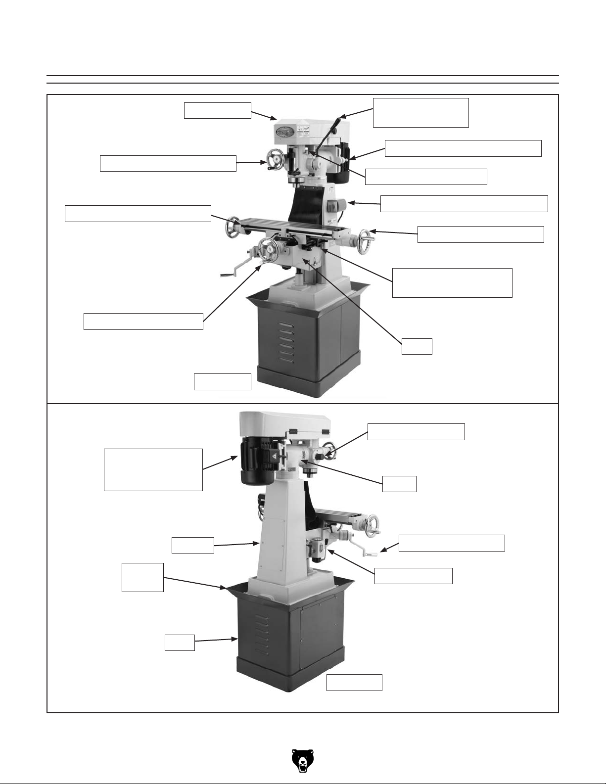
Identification
V-Belt Cover
Fine Downfeed Handwheel
Longitudinal Limit Stop Track
Cross Feed Handwheel
Front View
Coarse Downfeed
Handle
V-Belt Tension Adjustment Bolt
Spindle Bearing Oil Cup
ON/OFF Spindle Direction Switch
X-Axis Crank Handwheel
Y-Axis Feed Limit Stop
Track
Knee
Motor 1 1⁄2 H P
110V/220V, Single
Phase
Column
Splash
Pan
Base
Downfeed Selector
Turret
Z-Axis Crank Handle
One-Shot Oiler
Rear View
Figure 1. Vertical mill identification (Model G0728 shown).
Model G0728–31 (Mfg. Since 11/11)
-3-
Page 6

Machine Data Sheet
MODEL G0728/G0729/G0730/G0731
VERTICAL MILLING MACHINES
Model Number
Product Dimensions
Weight
Width x Depth x Height
Footprint Size (Length x Width)
Shipping Dimensions
Type
Content
Weight
Length x Width x Height
Electrical
Power Requirement
Prewired Voltage
Full Load Current Rating
Minimum Circuit Size
Switch
Switch Voltage
Cord Length
Cord Gauge
Plug Included
Included Plug Type
Recommended Plug/Outlet Type
Motor
Type
Horsepower
Voltage
Prewired
Phase
Amps
Speed
Cycle
Number of Speeds
Power Transfer
Bearing
G0728 G0729 G0730 G0731
660 lbs. 671 lbs. 924 lbs. 935 lbs.
3
45
⁄4" x 49 3⁄4" x 68" 40 1⁄2" x 42 3⁄4" x 67"
1
⁄2" x 21" 19" x 36"
27
Wood Crate
Machine
770 lbs. 781 lbs. 1078 lbs. 1089 lbs.
42" x 42" x 71" 44" x 44" x 76"
110V/220V, Single-Phase, 60 Hz
110V
18A at 110V; 9A at 220V
20A at 110V; 15A at 220V
Forward/Reverse Rotary Switch
110V/220V
72"
14 AWG
Yes
NEMA 5-15
NEMA 6-15 for 220V
TEFC Capacitor Start Induction
1
1
⁄2
110V/220V
110V
Single-Phase
18A/9A
1725 RPM
60 Hz
1
V-Belt Drive
Shielded and Permanently Lubricated
Operation Info
Spindle Travel
data sheet
-4-
3" 3
Models G0728–31 (Mfg. Since 11/11)
1
⁄2"
Page 7

Model Number
Model Number
Operation Info (cont'd)
Swing
Longitudinal Table Travel
Cross Table Travel
Knee Travel
Head Swivel (Left-to-right)
Turret/Column Swivel (Left and Right)
Max. Distance Spindle to Column
Max. Distance Spindle to Table
Drilling Capacity for Cast Iron
Drilling Capacity for Steel
Number of Vertical Spindle Speeds
Range of Vertical Spindle Speeds
(RPM)
Quill Diameter
Table Info
Table Length
Table Width
Table Thickness
Number of T-Slots
T-Slots Width
T-Slots Height
T-Slots Centers
Stud Size
Spindle Info
Spindle Taper
End Milling Capacity
Face Milling Capacity
Drawbar Diameter
Drawbar TPI
Drawbar Length
Spindle Bearings
G0728 G0729 G0730 G0731
G0728 G0729 G0730 G0731
13" 14"
5
⁄8" 18"
15
3
6" 7
1
⁄2" 17 3⁄4"
13
⁄4"
45° Left/Right
360°
1
⁄2" 7"
6
1
⁄4" 20"
12
1"
3
⁄4"
9
230, 320, 570, 670, 1200, 1420, 1650,
2170, 2520
270, 420, 490, 950, 1110, 1410, 1720,
2050, 3200
2.950"
26" 30"
1
⁄8" 8"
6
3
⁄4" 2"
1
3
9
⁄16"
13
⁄16"
11
⁄16" 2 3⁄16"
1
3
⁄8"
1
⁄2"
7
⁄8"
R8
3
⁄4" 1"
3"
7
⁄16"
20 TPI
3
12" 12
⁄8"
Angular Contact Bearing
Leadscrew Info
Leadscrew Diameter
Leadscrew TPI
Leadscrew Length
Construction
Spindle Housing/Quill
Table
Head/Column/Base
Stand
Paint
Other Specifications
Warranty
Country of Origin
Model G0728–31 (Mfg. Since 11/11)
7
⁄8"
8 TPI
35" 41"
Chrome-Plated Cast Iron Chrome-Plated Steel
Precision-Ground Cast Iron
Cast Iron
Stamped Steel Cast Iron
Epoxy
1 Year
Taiwan
-5-
Page 8

SECTION 1: SAFETY
For Your Own Safety, Read Instruction
Manual Before Operating This Machine
The purpose of safety symbols is to attract your attention to possible hazardous conditions.
This manual uses a series of symbols and signal words intended to convey the level of importance of the safety messages. The progression of symbols is described below. Remember that
safety messages by themselves do not eliminate danger and are not a substitute for proper
accident prevention measures. Always use common sense and good judgment.
Indicates an imminently hazardous situation which, if not avoided,
WILL result in death or serious injury.
Indicates a potentially hazardous situation which, if not avoided,
COULD result in death or serious injury.
Indicates a potentially hazardous situation which, if not avoided,
MAY result in minor or moderate injury. It may also be used to alert
against unsafe practices.
This symbol is used to alert the user to useful information about
NOTICE
proper operation of the machine.
Safety Instructions for Machinery
OWNER’S MANUAL. Read and understand this
owner’s manual BEFORE using machine.
TRAINED OPERATORS ONLY. Untrained operators have a higher risk of being hurt or killed.
Only allow trained/supervised people to use this
machine. When machine is not being used, disconnect power, remove switch keys, or lock-out
machine to prevent unauthorized use—especially
around children. Make workshop kid proof!
DANGEROUS ENVIRONMENTS. Do not use
machinery in areas that are wet, cluttered, or have
poor lighting. Operating machinery in these areas
greatly increases the risk of accidents and injury.
MENTAL ALERTNESS REQUIRED. Full mental
alertness is required for safe operation of machinery. Never operate under the influence of drugs or
alcohol, when tired, or when distracted.
ELECTRICAL EQUIPMENT INJURY RISKS. You
can be shocked, burned, or killed by touching live
electrical components or improperly grounded
machinery. To reduce this risk, only allow qualified
service personnel to do electrical installation or
repair work, and always disconnect power before
accessing or exposing electrical equipment.
DISCONNECT POWER FIRST.
nect machine from power supply BEFORE making
adjustments, changing tooling, or servicing machine.
This prevents an injury risk from unintended startup
or contact with live electrical components.
EYE PROTECTION. Always wear ANSI-approved
safety glasses or a face shield when operating or
observing machinery to reduce the risk of eye
injury or blindness from flying particles. Everyday
eyeglasses are not approved safety glasses.
Always discon-
-6-
Models G0728–31 (Mfg. Since 11/11)
Page 9

WEARING PROPER APPAREL. Do not wear
clothing, apparel or jewelry that can become
entangled in moving parts. Always tie back or
coverlong hair. Wearnon-slipfootwearto avoid
accidentalslips,whichcouldcause lossofworkpiececontrol.
hAzARdOus dusT. Dust created while using
machinery may cause cancer, birth defects, or
long-term respiratory damage.Be aware ofdust
hazardsassociatedwitheachworkpiecematerial,
andalwayswearaNIOSH-approvedrespiratorto
reduceyourrisk.
hEARING PROTECTION. Always wear hearing protection when operatingor observingloud
machinery. Extended exposure to this noise
withouthearing protectioncancause permanent
hearingloss.
REMOVE AdJusTING TOOLs. Tools left on
machinery can become dangerous projectiles
uponstartup.Neverleavechuckkeys,wrenches,
or any other tools on machine. Always verify
removalbeforestarting!
INTENdEd usAGE. Only use machine for its
intendedpurposeandnevermakemodifications
not approved by Grizzly. Modifying machine or
using it differently than intended may result in
malfunctionormechanicalfailurethatcanleadto
seriouspersonalinjuryordeath!
AWKWARd POsITIONs. Keep proper footing
andbalanceatalltimeswhenoperatingmachine.
Donotoverreach!Avoidawkwardhandpositions
that make workpiece controldifficult orincrease
the
riskofaccidentalinjury.
ChILdREN & BYsTANdERs. Keepchildrenand
bystandersatasafedistancefromtheworkarea.
Stopusingmachineiftheybecomeadistraction.
FORCING MAChINERY.Donotforcemachine.
Itwill dothejob saferand better atthe rate for
whichitwasdesigned.
NEVER sTANd ON MAChINE. Serious injury
may occur if machine is tipped or if thecutting
toolisunintentionallycontacted.
sTABLE MAChINE. Unexpectedmovementduring operation greatly increases risk of injury or
lossofcontrol. Beforestarting,verifymachineis
stableandmobilebase(ifused)islocked.
usE RECOMMENdEd ACCEssORIEs.Consult
thisowner’smanualorthemanufacturerforrecommended accessories.Using improper accessorieswillincreasetheriskofseriousinjury.
uNATTENdEd OPERATION. To reduce the
risk ofaccidental injury, turn machine offand
ensure all moving parts completely stop before
walking away. Never leave machine running
whileunattended.
MAINTAIN WITh CARE.Followallmaintenance
instructions and lubrication schedules to keep
machine in good working condition. A machine
that is improperly maintained could malfunction,
leadingtoseriouspersonalinjuryordeath.
ChECK dAMAGEd PARTs. Regularly inspect
machine for any condition that may affect safe
operation.Immediatelyrepairorreplacedamaged
ormis-adjustedpartsbeforeoperatingmachine.
MAINTAIN POWER CORds. When disconnecting cord-connected machines from power, grab
andpulltheplug—NOTthecord.Pullingthecord
may damage the wires inside. Do not handle
cord/plugwithwethands.Avoidcorddamageby
keepingitawayfromheatedsurfaces,hightraffic
areas,harshchemicals,andwet/damplocations.
GuARds & COVERs.Guardsandcoversreduce
accidental contact with moving parts or flying
debris. Make sure they are properly installed,
undamaged,andworkingcorrectly.
Model G0728–31 (Mfg. Since 11/11)
EXPERIENCING dIFFICuLT I E s. If at any time
youexperiencedifficultiesperformingtheintendedoperation,stopusingthemachine!Contactour
TechnicalSupportat(570)546-9663.
-7-
Page 10

Additional Safety Instructions For Mills
UNDERSTANDING CONTROLS: The mill is a
complex machine that presents severe cutting or
entanglement hazards if used incorrectly. Make
sure you understand the use and operation of all
controls before you begin milling.
SAFETY ACCESSORIES: Flying chips or debris
from the cutting operation can cause eye injury
or blindness. Always use a chip guard in addition
to your safety glasses, or use a face shield when
milling.
WORK HOLDING: Milling a workpiece that is not
properly clamped to the table could cause the
workpiece to be thrown at the operator with deadly
force! Before starting the machine, be certain
the workpiece has been properly clamped to the
table. NEVER hold the workpiece by hand during
operation.
SPINDLE SPEED: To avoid tool or workpiece
breakage that could send flying debris at the
operator and bystanders, use the correct spindle
speed and feed rate for the operation. Allow the
mill to gain full speed before beginning the cut.
SPINDLE DIRECTION CHANGE: Changing
spindle rotation direction while it is spinning could
lead to gear damage or impact injury from broken
tool or workpiece debris. ALWAYS make sure the
spindle has completely stopped before changing
spindle direction.
STOPPING SPINDLE: To reduce the risk of
hand injuries or entanglement hazards, DO NOT
attempt to stop the spindle with your hand or a
tool. Allow the spindle to stop on its own or use
the spindle brake.
CHIP CLEANUP: Chips from the operation are
sharp and hot and can cause cuts or burns. Using
compressed air to clear chips could cause them
to fly into your eyes and may drive them deep into
the working parts of the machine. Use a brush or
vacuum to clear away chips and debris from the
machine or workpiece and NEVER clear chips
while the spindle is turning.
MACHINE CARE AND MAINTENANCE:
Operating the mill with excessively worn or damaged machine parts increases the risk of machine
or workpiece breakage, which could eject hazardous debris at the operator. Operating a mill that
is in poor condition will also reduce the quality of
the results. To reduce this risk, maintain the mill
in proper working condition by ALWAYS promptly
performing routine inspections and maintenance.
CUTTING TOOL USAGE: Cutting tools have
very sharp leading edges—handle them with
care! Using cutting tools that are in good condition
helps to ensure quality milling results and reduces
the risk of personal injury from broken tool debris.
Inspect cutting tools for sharpness, chips, or
cracks before each use, and ALWAYS make sure
the cutting tools are firmly held in place before
starting the machine.
Like all machinery there is potential danger when operating this mill. Accidents are frequently
caused by lack of familiarity or failure to pay attention. Use this mill with respect and caution to
reduce the risk of operator injury. If normal safety precautions are overlooked or ignored, serious
personal injury may occur.
-8-
Models G0728–31 (Mfg. Since 11/11)
Page 11

SECTION 2: POWER SUPPLY
Before installing the machine, consider the availability and proximity of the required power supply
circuit. If an existing circuit does not meet the
requirements for this machine, a new circuit must
be installed. To minimize the risk of electrocution,
fire, or equipment damage, installation work and
electrical wiring must be done by an electrican or
qualified service personnel in accordance with all
applicable codes and standards.
Electrocution, fire, or
equipment damage may
occur if machine is not
correctly grounded and
connected to the power
The full-load current rating is the amperage a
machine draws at 100% of the rated output power.
On machines with multiple motors, this is the
amperage drawn by the largest motor or sum of all
motors and electrical devices that might operate
at one time during normal operations.
The full-load current is not the maximum amount
of amps that the machine will draw. If the machine
is overloaded, it will draw additional amps beyond
the full-load rating.
If the machine is overloaded for a sufficient length
of time, damage, overheating, or fire may result—
especially if connected to an undersized circuit.
To reduce the risk of these hazards, avoid overloading the machine during operation and make
sure it is connected to a power supply circuit that
meets the requirements in the following section.
For your own safety and protection of
Note: The circuit requirements listed in this manual apply to a dedicated circuit—where only one
machine will be running at a time. If this machine
will be connected to a shared circuit where multiple machines will be running at the same time,
consult a qualified electrician to ensure that the
circuit is properly sized for safe operation.
A power supply circuit includes all electrical
equipment between the breaker box or fuse panel
in the building and the machine. The power supply circuit used for this machine must be sized to
safely handle the full-load current drawn from the
machine for an extended period of time. (If this
machine is connected to a circuit protected by
fuses, use a time delay fuse marked D.)
This machine can be converted to operate on a
220V power supply (refer to Voltage Conversion
instructions). This power supply must have a verified ground and meet the following requirements:
This machine is prewired to operate on a 110V
power supply circuit that has a verified ground and
meets the following requirements:
Availability
supply.
Full-Load Current Rating
Circuit Information
property, consult an electrician if you are
unsure about wiring practices or electrical
codes in your area.
Full-Load Current Rating at 110V ...... 18 Amps
Full-Load Current Rating at 220V ....... 9 Amps
Model G0728–31 (Mfg. Since 11/11)
Circuit Requirements for 110V
Nominal Voltage ...............................110V/120V
Cycle ..........................................................60 Hz
Phase ........................................... Single-Phase
Power Supply Circuit ......................... 20 Amps
Plug/Receptacle ............................. NEMA 5-15
Circuit Requirements for 220V
Nominal Voltage .............................. 220V/240V
Cycle ..........................................................60 Hz
Phase ........................................... Single-Phase
Power Supply Circuit ......................... 15 Amps
Plug/Receptacle ............................. NEMA 6-15
-9-
Page 12

Improper connection of the equipment-grounding
wire can result in a risk of electric shock. The
wire with green insulation (with or without yellow
stripes) is the equipment-grounding wire. If repair
or replacement of the power cord or plug is necessary, do not connect the equipment-grounding
wire to a live (current carrying) terminal.
Check with a qualified electrician or service personnel if you do not understand these grounding
requirements, or if you are in doubt about whether
the tool is properly grounded. If you ever notice
that a cord or plug is damaged or worn, disconnect it from power, and immediately replace it with
a new one.
We do not recommend using an extension cord
with this machine.
cord, only use it if absolutely necessary and only
on a temporary basis.
Extension cords cause voltage drop, which may
damage electrical components and shorten motor
life. Voltage drop increases as the extension cord
size gets longer and the gauge size gets smaller
(higher gauge numbers indicate smaller sizes).
Any extension cord used with this machine must
contain a ground wire, match the required plug
and receptacle, and meet the following requirements:
Grounding Requirements
This machine MUST be grounded. In the event
of certain malfunctions or breakdowns, grounding
reduces the risk of electric shock by providing a
path of least resistance for electric current.
For 110V operation: This machine is equipped
with a power cord that has an equipment-grounding wire and a grounding plug (see following figure). The plug must only be inserted into a matching receptacle (outlet) that is properly installed
and grounded in accordance with all local codes
and ordinances.
For 220V operation: The plug specified under
“
page has a grounding prong that must be attached
to the equipment-grounding wire on the included
power cord. The plug must only be inserted into
a matching receptacle (see following figure) that
is properly installed and grounded in accordance
with all local codes and ordinances.
it will not fit the outlet, have a qualified
electrician install the proper outlet with a
GROUNDED
5-15 RECEPTACLE
Grounding Prong
GROUNDED
6-15 RECEPTACLE
Current Carrying Prongs
6-15 PLUG
Grounding Prong
Figure 3. Typical 6-15 plug and receptacle.
5-15 PLUG
Neutral Hot
Figure 2. Typical 5-15 plug and receptacle.
SHOCK HAZARD!
Two-prong outlets do not meet the grounding
requirements for this machine. Do not modify
or use an adapter on the plug provided—if
verified ground.
Circuit Requirements for 220V” on the previous
-10 -
Extension Cords
If you must use an extension
Minimum Gauge Size ...........................14 AWG
Maximum Length (Shorter is Better).......50 ft.
Models G0728–31 (Mfg. Since 11/11)
Page 13

Voltage Conversion
To convert this mill for 220V power, you must rewire the motor and install a NEMA 6-15 plug and
receptacle.
Motor prewired
for 110V
3
Refer to Page 39 for the full Wiring Diagram.
You MUST disconnect the
mill from the power source
before beginning any of
the following 220V conversion procedures to avoid
serious personal injury or
death by electrocution.
Tools/Items Needed Qty
Phillips Head Screwdriver #2 ............................ 1
Wire Nut ............................................................ 1
To rewire the motor:
1. Remove the cover of the motor wiring junc-
tion box.
1
4
2
5
6
Ground
Figure 4. Motor configured for 110V operation.
Motor Rewired for 220V
4
2. Re-configure the motor wiring by removing
wires 1, 3, 4, 2, 5, and 6 from the terminal
block (see Figure 4).
3. Replace wires 4, 1, and 6 on the terminal
block, as shown in Figure 5.
4. Use the wire nut to secure wires 2, 3, and 5
together, as shown in Figure 5.
5. Replace the cover of the motor wiring junction box.
Replacing the Plug
Replace the molded NEMA 5-15 plug with a
NEMA 6-15 by removing the original and installing the new plug according to the manufacturer's
instructions.
1
6
3
2
5
Ground
Figure 5. Motor configured for 220V operation.
Covers, guards, and safety devices on
this machine are provided for your safety.
Always keep them secured in place before
connecting the machine to power to avoid
serious personal injury.
Model G0728–31 (Mfg. Since 11/11)
-11-
Page 14

SECTION 3: SETUP
Your machine was carefully packaged for safe
transportation. Remove the packaging materials
from around your machine and inspect it. If you
discover any damage, please call us immediately
at (570) 546-9663
Save the containers and all packing materials for
possible inspection by the carrier or its agent.
Otherwise, filing a freight claim can be difficult.
When you are completely satisfied with the condition of your shipment, inventory the contents.
Keep children and pets away
from plastic bags or packing
materials shipped with this
Setup Safety
This machine presents
serious injury hazards
to untrained users. Read
through this entire manual to become familiar with
the controls and operations before starting the
machine!
Wear safety glasses during the entire setup process!
Needed for Setup
The following items are needed to complete the
setup process, but are not included with your
machine:
Description Qty
• Assistants ................................................... 2
• Precision Level ........................................... 1
• External Retaining Ring Pliers ................... 1
• Safety Glasses ........................ 1 Per Person
• Lifting Straps
(rated for at least 1500 lbs.) ........................ 2
• Power Lifting Equipment
(rated for at least 1500 lbs.) ........................ 1
• Machine Mounting Hardware ..... As Needed
• Cleaning Solvent & Rags ........... As Needed
• Wrench
1
⁄2 " ................................................. 1
Unpacking
This vertical mill is a
heavy machine. Serious
personal injury may
occur if safe moving
methods are not used.
To be safe, get assistance and use power
equipment rated for at
least 1500 lbs. to move
the shipping crate and
remove the machine
from the crate.
for advice.
SUFFOCATION HAZARD!
machine. Discard immediately.
-12-
Models G0728–31 (Mfg. Since 11/11)
Page 15

Inventory
The unpainted surfaces of your machine are
coated with a heavy-duty rust preventative that
prevents corrosion during shipment and storage.
This rust preventative works extremely well, but it
will take a little time to clean.
Be patient and do a thorough job cleaning your
machine. The time you spend doing this now will
give you a better appreciation for the proper care
of your machine's unpainted surfaces.
There are many ways to remove this rust preventative, but the following steps work well in a wide
variety of situations. Always follow the manufacturer’s instructions with any cleaning product you
use and make sure you work in a well-ventilated
area to minimize exposure to toxic fumes.
Before cleaning, gather the following:
•
•
•
•
Basic steps for removing rust preventative:
1.
2.
amount of cleaner/degreaser, then let it soak
3. Wipe off the surfaces. If your cleaner/degreas-
off easily. If you have a plastic paint scraper,
scrape off as much as you can first, then wipe
4.
then coat all unpainted surfaces with a quality
Avoid chlorine-based solvents, such as
The following is a description of the main components shipped with your machine. Lay the components out to inventory them.
Note: If you can't find an item on this list, check
the mounting location on the machine or examine
the packaging materials carefully. Occasionally
we pre-install certain components for shipping
purposes.
Inventory: (Figure 6) Qty
A. Hex Wrench 4mm ....................................... 1
B. Hex Wrench 5mm ....................................... 1
C. Double End Wrench 12mm & 14mm .......... 1
D. Handwheel Handles ................................... 3
E. Crank Arm (not shown) ............................... 1
Cleanup
Disposable Rags
Cleaner/degreaser (WD•40 works well)
Safety glasses & disposable gloves
Plastic paint scraper (optional)
A
B
Figure 6. Model G0728 inventory.
If any nonproprietary parts are missing (e.g. a
nut or a washer), we will gladly replace them; or
for the sake of expediency, replacements can be
obtained at your local hardware store.
C
D
Put on safety glasses.
Coat the rust preventative with a liberal
for 5–10 minutes.
er is effective, the rust preventative will wipe
off the rest with the rag.
Repeat Steps 2–3 as necessary until clean,
metal protectant to prevent rust.
NOTICE
acetone or brake parts cleaner, that may
damage painted surfaces.
Model G0728–31 (Mfg. Since 11/11)
-13-
Page 16
Site Considerations
Weight Load
Physical Environment
Place this machine near an existing power source.
Shadows, glare, or strobe effects that may distract
Refer to the Machine Data Sheet for the weight
of your machine. Make sure that the surface upon
which the machine is placed will bear the weight
of the machine, additional equipment that may be
installed on the machine, and the heaviest workpiece that will be used. Additionally, consider the
weight of the operator and any dynamic loading
that may occur when operating the machine.
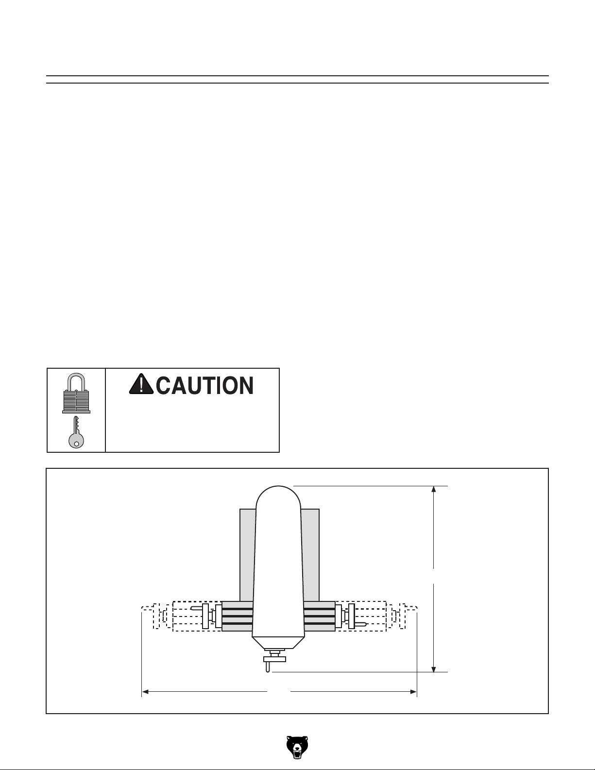
Space Allocation
Consider the largest size of workpiece that will
be processed through this machine and provide
enough space around the machine for adequate
operator material handling or the installation of
auxiliary equipment. With permanent installations,
leave enough space around the machine to open
or remove doors/covers as required by the maintenance and service described in this manual.
See below for required space allocation.
Children or untrained people
may be seriously injured by
this machine. Only install in an
access restricted location.
The physical environment where the machine is
operated is important for safe operation and longevity of machine components. For best results,
operate this machine in a dry environment that is
free from excessive moisture, hazardous chemicals, airborne abrasives, or extreme conditions.
Extreme conditions for this type of machinery are
generally those where the ambient temperature
range exceeds 41°–104°F; the relative humidity
range exceeds 20–95% (non-condensing); or the
environment is subject to vibration, shocks, or
bumps.
Electrical Installation
Make sure all power cords are protected from
traffic, material handling, moisture, chemicals,
or other hazards. Make sure to leave access to
a means of disconnecting the power source or
engaging a lockout/tagout device, if required.
Lighting
Lighting around the machine must be adequate
enough that operations can be performed safely.
or impede the operator must be eliminated.
-14-
68"
Figure 7. Minimum working clearances.
Models G0728–31 (Mfg. Since 11/11)
48"
Page 17

Moving & Placing
2. Use a 1⁄2" wrench to unbolt the mill from the
pallet.
Base Unit
The vertical mill is a
heavy machine. Serious
personal injury may
occur if safe moving
methods are not used.
To be safe, get assistance and use power
equipment rated for at
least 1500 lbs. to move
the shipping crate and
remove the machine
from the crate.
To move and place this mill:
1. After removing the crate from the shipping
pallet, wrap lifting straps around the turret, as
shown in Figure 8, and securely attach them
to your power lifting equipment.
3. With assistance to steady the machine, move
it as close to the prepared location as possible.
4. Lift it just enough to clear the pallet and any
floor obstacles, then situate it in its final position.
5. When mounting the machine to the floor, use
a precision level to make sure the table is
level from side to side and front to back.
Note: If necessary, use shims to make sure
there are no gaps between the base and the
floor to avoid cracking or warping the cast
iron.
Lifting Straps
Turret
Figure 8. Positioning the lifting straps.
Model G0728–31 (Mfg. Since 11/11)
-15-
Page 18
Anchoring the machine to the floor prevents it
from tipping or shifting and reduces any vibration
that may occur during operation, resulting in a
machine runs slightly quieter and feels more solid.
If the machine will be installed in a commercial or
workplace setting, or if it is permanently connected (hardwired) to the power supply, local codes
may require that it be anchored to the floor.
If not required by any local codes, fastening the
machine to the floor is an optional step. If you
choose not to do this with your machine, we recommend placing it on machine mounts, as these
provide an easy method for leveling and they have
vibration-absorbing pads.
Anchoring to Floor
Lag shield anchors with lag screws (see below)
are a popular way to anchor machinery to a concrete floor, because the anchors sit flush with the
floor surface, making it easy to unbolt and move
the machine later, if needed. However, anytime
local codes apply, you MUST follow the anchoring
methodology specified by the code.
Anchoring to Concrete Floors
NOTICE
Anchor studs are stronger and more permanent alternatives to lag shield anchors;
however, they will stick out of the floor,
which may cause a tripping hazard if you
decide to move your machine.
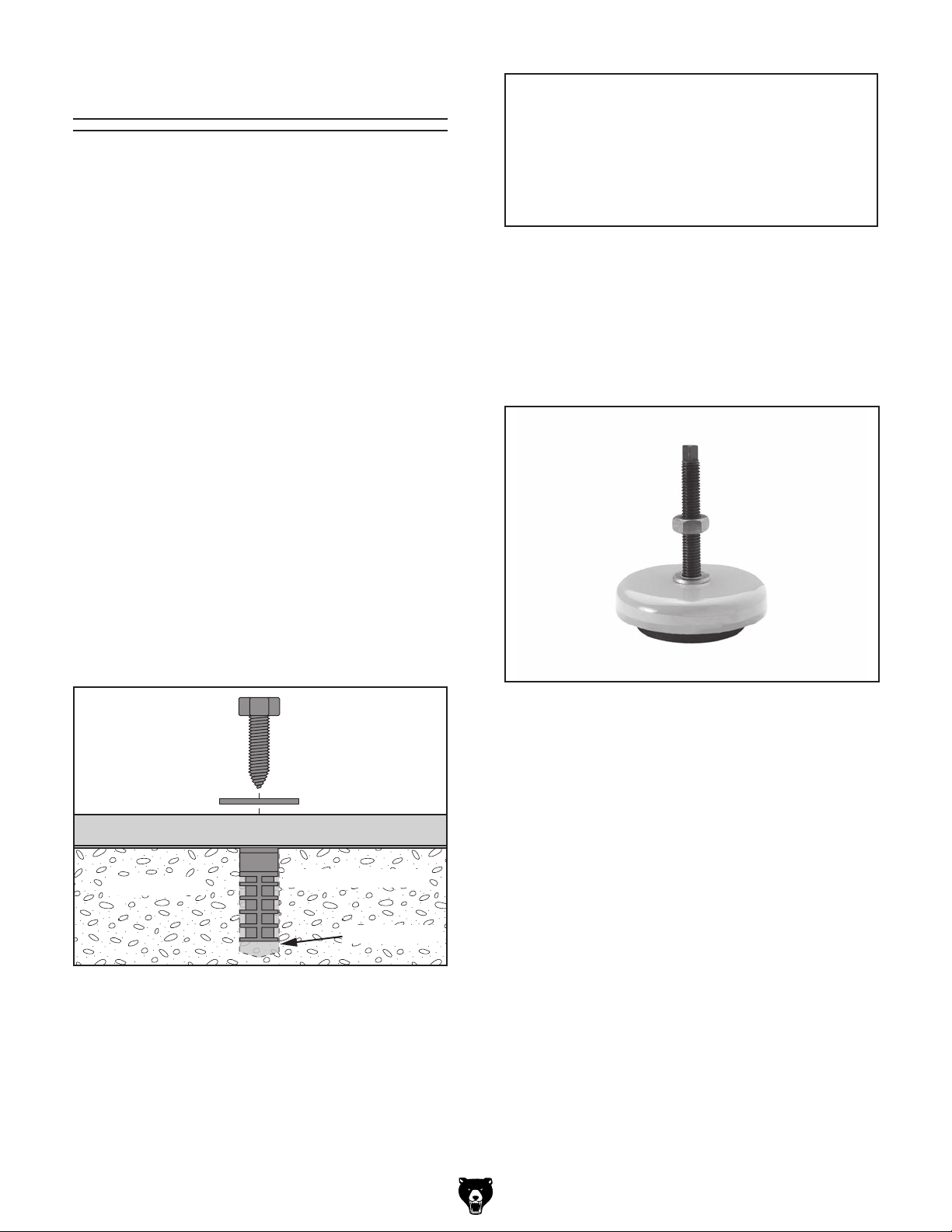
Using Machine Mounts
Using machine mounts, shown in Figure 10, gives
the advantage of fast leveling and vibration reduction. The large size of the foot pads distributes
the weight of the machine to reduce strain on the
floor.
Lag Screw
Machine Base
Concrete
Figure 5. Popular method for anchoring
machinery to a concrete floor.
-16 -
Flat Washer
Lag Shield Anchor
Drilled Hole
Figure 10. Machine mount example.
Models G0728–31 (Mfg. Since 11/11)
Page 19

Assembly
Gather the needed tools and components listed in
Needed for Setup on Page 12.
To assemble the mill:
1. Secure the three handles to the handwheels,
as shown in Figures 11 and 12.
2. Remove the retaining ring from the end of the
vertical crank screw, install the crank handle,
then re-install the retaining ring, as shown in
Figure 13.
Retaining Ring
Handle
Figure 11. Right table handle attached to
handwheel (left table handle not shown).
Handle
Figure 12. Cross feed handle attached to
handwheel.
Figure 13. Vertical crank handle properly
installed.
Model G0728–31 (Mfg. Since 11/11)
-17-
Page 20

Initial Lubrication
After you have completed all previous setup
instructions and circuit requirements, the machine
is ready to be connected to the power supply.
To avoid unexpected startups or property damage, use the following steps whenever connecting
or disconnecting the machine.
1. TurnthemachinepowerswitchOFF.
2.
matching
is
1. TurnthemachinepowerswitchOFF.
2.
completely
cord
This mill has numerous moving metal-to-metal
contacts that require proper lubrication to help
ensure efficient and long-lasting mill operation.
However, some lubrication must be performed
manually. Lubricate the spindle and quill before
proceeding to the Test Run or Spindle Break-In
sections.
NOTICE
Failure to follow reasonable lubrication
practices as outlined in this manual for your
mill could lead to premature failure of your
mill and will void the warranty.
To lubricate the spindle do the following steps:
1. Use the coarse downfeed handle, completely
feed out the quill and lock it in position with
the quill lock. Rub the quill down with a lightly
oiled rag.
Power Connection
Connecting Power
Insert the power cord plug into a
power supply receptacle. The machine
nowconnectedtothepowersource.
2. While holding the coarse downfeed handle,
release the quill lock and return the quill to its
initial position.
3. Add 6 to 10 drops of oil to the spindle lubrication cup and wait 5–10 minutes (see
Figure 14).
Figure 14. Spindle lubrication cup location.
Spindle
Lubrication
Cup
Figure 15. Connecting power.
Disconnecting Power
Graspthemoldedplugandpullit
outofthereceptacle.Donotpullbythe
asthismaydamagethewiresinside.
Note: The spindle lubrication cup is a gradual
gravity powered system. Extending the quill
at this stage will empty the cup too rapidly to
effectively lubricate the spindle.
-18-
Figure 16. Disconnecting power.
Models G0728–31 (Mfg. Since 11/11)
Page 21

Test Run
Once the assembly is complete, test run your
machine to make sure it runs properly and is
ready for regular operation. The test run consists
of verifying the following: 1) The motor powers up
and runs correctly and 2) the spindle switch works
correctly.
If, during the test run, you cannot easily locate
the source of an unusual noise or vibration, stop
using the machine immediately, then review
Troubleshooting on Page 34.
To test run the machine:
1. Make sure you understand the safety instruc-
tions at the beginning of the manual and that
the machine is set up properly.
2. Make sure all tools and objects used during
setup are cleared away from the machine.
3. Make sure the spindle is lubricated (refer to
Initial Lubrication on Page 18 for detailed
instructions).
4. Ensure the spindle switch is in the OFF position.
If you cannot find a remedy, contact our Tech
Support at (570) 546-9663 for assistance.
Before starting the mill, make sure you
have performed the preceding assembly
instructions, and you have read through the
rest of the manual and are familiar with the
various functions and safety features on
this machine. Failure to follow this warning
could result in serious personal injury or
even death!
NOTICE
Complete the Initial lubrication procedures
on Page 18 before proceeding. Failure to
follow reasonable lubrication practices as
outlined in this manual could lead to premature failure of your mill and will void the
warranty.
5. If it is not already, connect the machine to the
power source.
6. Verify that the machine is operating correctly
by turning the spindle switch to the FWD
position.
—When operating correctly, the machine
runs with little or no vibration or rubbing
noises.
— Investigate and correct strange or unusual
noises or vibrations before operating the
machine further. Always disconnect the
machine from power when investigating or
correcting potential problems.
7. Turn the spindle switch to the OFF position.
8. Turn the spindle switch to the REV position.
—When operating correctly, the machine
runs with little or no vibration or rubbing
noises.
Model G0728–31 (Mfg. Since 11/11)
— Investigate and correct strange or unusual
noises or vibrations before operating the
machine further. Always disconnect the
machine from power when investigating or
correcting potential problems.
When all of the Test Run procedures are successfully completed, proceed to Spindle Break-
In.
-19 -
Page 22

Spindle Break-In
It is essential to closely follow the proper break-in
procedures to ensure trouble-free performance of
this mill.
Do not attempt to perform the spindle breakin until successful completion of the Test
Run section on Page 19. Failure to complete
the test run of the machine increases the
chance for serious injury or property damage.
NOTICE
Complete the Initial lubrication procedures
on Page 18 before proceeding. Failure to
follow reasonable lubrication practices as
outlined in this manual could lead to premature failure of your mill and will void the
warranty.
Successfully complete the spindle break-in
procedure to avoid rapid wear of spindle
components when placed into operation.
To perform the spindle break-in procedure:
1. Adjust the pulleys to set the spindle speed
to 230 RPM (G0728/G0729), or 270 RPM
(G0730/G0731) (see Page 27 for detailed
instruction on Adjusting Spindle Speed).
2. Turn the switch to the FWD position.
3. Let the mill run at this speed for 20 minutes,
then turn the spindle OFF and wait for it to
stop.
4. Turn the spindle direction switch to the REV
position, and let it run for another 20 minutes.
5. Set the spindle speed at 1650 RPM (G0728/
G0729), or 1720 RPM (G0730/G0731), then
repeat Steps 2–4.
6. Turn the mill OFF. The spindle break-in is
now complete and the machine is ready for
operation.
-20-
Models G0728–31 (Mfg. Since 11/11)
Page 23

SECTION 4: OPERATIONS
Operation Safety
To reduce the risk of
serious injury when using
this machine, read and
understand this entire
manual before beginning
any operations.
Damage to your eyes or face could result
from using this machine without proper protective gear. Always wear safety glasses or a
face shield when operating this machine.
Basic Controls
This vertical mill is equipped with an ON/OFF
spindle direction switch, as shown in Figure 17.
The mill can be turned ON in the Forward (FWD)
direction, and turned ON in the Reverse (REV)
direction. Returning the switch to the vertical OFF
position turns the motor off.
OFF
REV
FWD
Loose hair, clothing, or
jewelry could get caught
in machinery and cause
serious personal injury.
Keep these items away
from moving parts at all
times to reduce this risk.
NOTICE
If you have never used this type of machine
or equipment before, we strongly recommend that you read books, trade magazines,
or get formal training before beginning any
projects. Regardless of the content in this
section, Grizzly Industrial will not be held
liable for accidents caused by lack of training.
Figure 17. Illustration of spindle direction switch
Model G0728–31 (Mfg. Since 11/11)
-21-
Page 24

Table Movement
This mill table has three paths of movement that
are controlled by the corresponding handwheels
or the vertical crank handle (see Figure 18).
Logitudinal (X-Axis)
or Left & Right
Knee Lock
Saddle Lock
Cross Feed
(Y-Axis) or
In & Out
Vertical (Z-Axis) or
Up & Down
Figure 18. Three movement paths of the mill
table.
The graduated dials are marked in increments of
0.001", with one full revolution moving the table
0.12 5".
Locks
The table of this vertical mill has locks to secure
the table in position along each axis of movement. Locking the table reduces unwanted movement and reduces error in milling operations.
Use the table, saddle, and knee locks shown in
Figures 19 –20 to secure the table in position.
Figure 20. Saddle and knee locks.
Limit Stops
Limit stops increase repeatability in milling
operations. Positioning the stops along the table
slots limits the distance the table or saddle can
travel (see Figures 21–22).
Longitudinal Limit
Stops
Limit Block
Figure 21. Table limit stops and block.
-22-
Limit Block
Table Locks
Cross Limit Stops
Figure 22. Cross limit stops and block.
Figure 19. Table locks.
Models G0728–31 (Mfg. Since 11/11)
Page 25

Longitudinal Power Feed System
The G0729 and G0731 vertical mills are equipped
with a longitudinal power feed and limit switch for
controlled X-axis table movement. Refer to Figure
23 and the descriptions below to understand the
functions of these devices.
Tools Needed Qty
Wrench or Socket 12mm ................................... 1
To operate the longitudinal power feed:
1. Loosen the table locks (see Figure 24).
I
A
B
D
C
E
F
H
G
Figure 23. Longitudinal power feed system.
A. Limit Switch: Stops powered table move-
ment when either limit stop presses a plunger
on the switch.
B. Limit Stop: Activates the limit switch. Secure
these devices along the table to limit longitudinal movement.
C. Rapid Movement Button: When pressed,
moves the table at the maximum speed in the
direction selected.
Limit Stop
Limit Switch
Table Locks
Figure 24. Example of table locks, limit switch,
and limit stop.
2. Position the limit stops along the table to
confine the longitudinal distance you want
the table to travel, then tighten the hex bolts
to secure them in place.
3. Move the power feed direction lever to the
center or neutral position, then plug the
power feed power cord into an appropriate
receptacle.
D. Direction Lever: Starts, reverses, and stops
longitudinal table movement.
E. Speed Dial: Controls the speed that the table
moves—turn the dial clockwise to increase
the speed.
F. ON/OFF Switch: The master power switch
for the power feed.
G. Power Lamp: Lights when the power feed is
turned ON.
H. Handwheel: Manually positions the table.
I. Graduated Dial: Marked in 0.001" incre-
ments, each complete revolution is equal to
0.200" of longitudinal table travel.
Model G0728–31 (Mfg. Since 11/11)
Be sure there is enough running clearance
between the table, spindle, vise/clamps,
or jigs before turning the power feed ON.
Failure to do so could result in injury from
tool breaking and pieces being thrown at
high speed.
-23-
Page 26

4. Rotate the speed dial to the minimum speed
(all the way to the left), and use the direction
lever to select the direction of table travel.
Head Tilting
5. Flip the ON/OFF switch up to turn the power
feed ON.
6. Adjust the speed dial to move the table at the
correct speed for your operation.
Note: Power feed rates are difficult to pre-
cisely adjust. We recommend that you experiment with different dial settings to find the
feed rate that best works for your operation.
7. When you are through using the power feed,
leave the direction lever in the center or
neutral position, and flip the ON/OFF switch
down to turn the power feed OFF.
Always keep the table locked in place
unless controlled movement is required
for your operation. Unexpected table movement during operations could cause the
cutter to bind with the workpiece, resulting
in personal injury, and possible damage to
the cutter and workpiece.
The head tilts 90° to the left or right (see
Figure 25).
Figure 25. Head tilted 45° to the left.
Tools Needed Qty
Wrench 17mm.................................................... 1
To tilt the head left or right:
1. DISCONNECT THE MILL FROM POWER!
2. Loosen the four hex nuts and lock washers
on both sides of the turret (see Figure 26).
Hex Nuts and
Lock Washers
(2 of 4)
Head Tilting
Scale
Figure 26. Head tilting hex nuts and lock
washers (2 of 4 shown).
-24-
Models G0728–31 (Mfg. Since 11/11)
Page 27

3. Tilt the head to the left or right and use the
head tilt scale to determine the angle of tilt.
4. Re-tighten the four hex nuts and lock washers
to secure the head.
Always lock the head in place after adjusting
tilt. Unexpected movement of the head
during operations could cause the cutter
to bind with the workpiece, resulting in
personal injury, and possible damage to the
cutter and workpiece.
Turret Rotation
The turret rotates 360° around the column (see
Figure 27).
To rotate the turret left or right:
1. DISCONNECT THE MILL FROM POWER!
2. Loosen the three hex nuts and lock washers
on the turret (see Figure 28).
Turret Hex Nuts and
Lock Washers (2 of 3)
Turret
Rotation
Scale
Figure 28. Turret rotation hex nuts and lock
washers (2 of 3 shown).
Figure 27. Head and turret rotated 45° to the
left.
Tools Needed Qty
Wrench 17mm.................................................... 1
3. Rotate the head and turret around the column
to the left or right using the turret rotation
scale to determine the amount of rotation.
4. Re-tighten the three hex nuts and lock washers to secure the head and turret in place.
Always lock the turret in place after rotation.
Unexpected movement of the head during
operations could cause the cutter to bind
with the workpiece, resulting in personal
injury, and possible damage to the cutter
and workpiece.
Model G0728–31 (Mfg. Since 11/11)
-25-
Page 28

Tramming Spindle
4. Center the parallel block under the spindle
and tighten the table, knee, and quill locks to
eliminate unwanted movement.
Tramming the spindle ensures that the spindle
and table are perpendicular along the X-axis (see
Figure 29). This operation should be performed
when returning the spindle to the vertical position
after operations in which the head was tilted.
Spindle
Z-Axis
90º
X-Axis
Table
Figure 29. Spindle perpendicular to the table in
the X-axis.
Tools Needed Qty
Wrench 17mm.................................................... 1
Dial Test Indicator .............................................. 1
Indicator Holder ................................................. 1
Precision Parallel Block ..................................... 1
To tram the spindle:
5. With the test indicator attached to the indica-
tor holder, mount the holder in the spindle.
Note: The goal is to adjust the head so that
the differences between the measurements
are zero within the capabilities of the test
indicator. However, specific tolerances will be
determined by each operation.
6. Measure spindle alignment along the X-axis at
one end of the parallel block (see Figure 30).
Indicator Holder
Spindle
Dial Test Indicator
Parallel Block
Table
Figure 30. Dial test indicator mounted.
7. Rotate the spindle by hand so that the indica-
tor rests on the other end of the parallel block
along the X-axis.
1. DISCONNECT THE MILL FROM POWER!
2. Loosen the 4 head tilt hex nuts and lock
washers.
Note: When tramming the spindle it is best to
tighten the nuts snug enough that the head
needs light taps with a rubber mallet to move.
This prevents the head from moving freely and
losing adjustments between measurements.
3. Ensure the table is free from chips and nicks
that may change the elevation of the parallel
block.
-26-
—If the indicator dial reads zero or is with-
in the acceptable tolerances, continue to
Step 8.
—If the indicator has moved from zero out-
side acceptable tolerances, adjust the tilt
of the head and repeat Steps 6 and 7.
8. Retighten the four hex nuts and lock washers.
Always lock the head in place after adjusting
tilt. Unexpected movement of the head
during operations could cause the cutter
to bind with the workpiece, resulting in
personal injury, and possible damage to the
cutter and workpiece.
Models G0728–31 (Mfg. Since 11/11)
Page 29

Adjusting Spindle
Speed
To select the correct spindle speed (RPM) for a
milling operation, you will need to: 1) Determine
the spindle speed needed for the workpiece,
and 2) configure the belts to provide the closest
calculated speed.
Calculating Spindle Speed
1. Use the table in Figure 31 to determine the
cutting speed or surface feet per minute
(SFM) required for the workpiece material.
Cutting Speeds for High Speed Steel (HSS)
Cutting Tools
Workpiece Material Cutting Speed (SFM)
Aluminum & alloys 300
Brass & Bronze 150
Copper 100
Cast Iron, soft 80
Cast Iron, hard 50
Mild Steel 90
Cast Steel 80
Alloy Steel, hard 40
Tool Steel 50
Stainless Steel 60
Titanium 50
Plastics 300-800
Wood 300-500
Note: For carbide cutting tools, double the cutting
speed. These values are a guideline only. Refer to
the MACHINERY'S HANDBOOK for more detailed
information.
Figure 31. Cutting speed table for HSS cutting
tools.
2. Measure the diameter of the cutting tool in
inches.
3. Use the following formula to calculate the
required spindle speed RPM:
Setting Spindle Speed
Tools Needed Qty
Wrench 24 mm .................................................. 2
To set the spindle speed:
1. DISCONNECT THE MILL FROM POWER.
2. Release motor pulley tension by loosening
the jam nut and then the tensioner bolt (see
Figure 32).
Tensioner Bolt
Jam
Nut
Figure 32. Tensioner bolt and jam nut location.
3. Using the table in Figure 33, arrange the
belts to provide the best RPM for the cutting
operation.
PULLEY ARRANGEMENT
A
B
C
D
I
II
III
G0728/29
G0730/31
A
670
950 420
1650 1200
1720 1110
SPINDLE RPM CHART
B
Figure 33. Vertical milling machine RPM table.
320
14202520 2170
14103200 2050
I
II
III
C
D
230
270
570
490
*Recommended
Cutting Speed (FPM) x 12
Tool Dia. (in inches) x 3.14
=
*Double if using carbide cutting tool
Model G0728–31 (Mfg. Since 11/11)
Spindle
Speed
(RPM)
4. Retension the belts to the proper tension (see
V-Belt Tensioning on Page 33).
-27-
Page 30

Downfeed Controls
A. Quill Dog: Moves with the quill. Use the
pointer on the side with the downfeed scale
to determine the depth of downfeed.
Refer to Figures 34–35 and the following descrip-
tions to understand the functions of the downfeed
controls that affect the travel of the quill, spindle,
an d cutter.
A
E
Figure 34. Downfeed controls viewed from the
H
B
D
right side.
F
C
G
B. Downfeed Scale: Displays in inches the
amount of quill travel.
C. Coarse Downfeed Handle: When this han-
dle is enabled with the downfeed selector, it
raises/lowers the quill quickly.
D. Quill Lock: Locks the quill in place but does
not affect spindle rotation.
E. Downfeed Stop & Lock: Stops downfeed
travel when the quill dog reaches this point.
Set the stop at any position along the
downfeed scale, then secure it in place by
tightening the lock up to it.
F. Graduated Scale: Displays quill travel in
0.001" increments when the fine downfeed
handwheel is used. One full revolution represents 0.080" of quill travel.
G. Fine Downfeed Handwheel: When this
handwheel is enabled with the downfeed
selector, it raises/lowers the quill in small
increments.
H. Downfeed Selector: Enables either the
coarse or fine downfeed control. Tighten
the selector to enable the fine downfeed
handwheel, and loosen it to enable the
coarse downfeed handle.
Figure 35. Downfeed controls viewed from the
left side.
-28-
Models G0728–31 (Mfg. Since 11/11)
Page 31

Loading/Unloading
Tooling
This mill is equipped with a 7⁄16"-20 drawbar (see
Figure 36). Use the drawbar to secure/remove
tooling during loading/unloading.
Adjustment
Hex Nut
Figure 36. Drawbar and adjustment nut.
3. Open the V-belt cover and rotate the adjust-
ment hex nut to the top of the drawbar to
extend the drawbar fully within the spindle
(see Figure 37).
Drawbar
Figure 37. Drawbar inserted through the top of
the spindle.
4. Align the tooling key way with the quill set
screw while pushing the tool firmly into the
spindle taper to seat it.
Tools Needed Qty
Wrench 19mm ................................................... 2
Loading Tooling
1. DISCONNECT THE MILL FROM POWER!
2. Clean any debris or oily substances from
the mating surfaces of the spindle and tool
tapers.
Cutting tools are sharp and can
easily cut your hands. Always protect your
hands when handling cutting tools.
5. While holding the tool in place with one hand,
thread the drawbar into the tool and hand
tighten.
6. To fully seat the tool into the spindle, use the
wrenches to tighten the drawbar adjustment
hex nut down to draw the tool up until it is
snug.
Note: Over-tightening the drawbar could
make removing the tool difficult.
Unloading Tooling
1. DISCONNECT THE MILL FROM POWER!
2. Keep one hand on the tool, loosen the adjust-
ment hex nut, then completely unthread the
drawbar.
— If the tool does not release from the
spindle as the drawbar is unthreaded, turn
the drawbar back into the tool one or two
threads, then tap the top of the drawbar
with a dead-blow hammer or rubber mallet
until the tool releases.
Model G0728–31 (Mfg. Since 11/11)
-29-
Page 32

ACCESSORIES
Installing unapproved accessories may
order online at www.grizzly.com or call 1-800-523-4777
SECTION 5: ACCESSORIES
cause machine to malfunction, resulting in
serious personal injury or machine damage.
To reduce this risk, only install accessories
recommended for this machine by Grizzly.
NOTICE
Refer to our website or latest catalog for
additional recommended accessories.
5
T10063—Milling Vise 12
T10064—Milling Vise 17
• Ultra precise in flatness, parallelism and verticality.
• Anti-lift mechanism ensures the workpiece
does not lift when jaws are tightened.
• Ductile iron body.
• Flame hardened vise bed and jaws.
• Sealed bearing system.
• 8200 lbs. of clamping pressure.
⁄16" x 69⁄16"
1
⁄8" x 83⁄4"
G1075—52-PC. Clamping Kit
This clamping kit includes 24 studs, 6 step block
pairs, 6 T-nuts, 6 flange nuts, 4 coupling nuts, and
6 end hold-downs. The rack is slotted so it can be
mounted close to the machine for easy access.
Made for
T20501—Face Shield Crown Protector 4"
T20502—Face Shield Crown Protector 7"
T20503—Face Shield Window
T20452—"Kirova" Anti-Reflective S. Glasses
T20451—"Kirova" Clear Safety Glasses
H0736—Shop Fox
H7194—Bifocal Safety Glasses 1.5
H7195—Bifocal Safety Glasses 2.0
H7196—Bifocal Safety Glasses 2.5
1
⁄2 " T-slots.
Figure 39. G1075 52-PC. Clamping Kit.
®
Safety Glasses
Figure 38. T10064 Milling vise (handle included,
but not shown.
-30-
T20502
T20503
H7194
Figure 40. Eye protection assortment.
Models G0728–31 (Mfg. Since 11/11)
T20452
T20451
H0736
Page 33

SECTION 6: MAINTENANCE
Cleaning &
Always disconnect power
to the machine before
performing maintenance.
Failure to do this may
result in serious personal injury.
Schedule
For optimum performance from your machine,
follow this maintenance schedule and refer to any
specific instructions given in this section.
Before Daily Operation:
• Check/tighten loose mounting bolts.
• Check/sharpen/replace worn or damaged
tooling.
• Check/repair/replace worn or damaged wires.
• Check for any other unsafe condition.
• Use the one-shot oiler (Page 32).
Every 8 Hours of Operation:
• Use the one-shot oiler (Page 32).
• Add oil to the spindle lubrication cup (Page 32).
• Clean the mill.
Every 40 Hours of Operation:
• Lubricate the vertical bevel gears (Page 32).
• Lubricate the longitudinal, cross, and vertical
leadscrews (Page 33).
Protecting
Use a brush and shop vacuum to remove chips
and debris from the mill. Never blow off the mill
with compressed air, as this will force metal chips
deep into the mechanisms and may injure yourself or bystanders.
Wipe built-up grime from the mill with a rag and a
mild solvent. Remove any rust from the unpainted
cast iron surfaces of this mill, then treat them with
regular applications of products such as Primrose
Armor Plate Way Oil, G96
SLIPIT
for more details).
®
, or Boeshield® T-9 (see Grizzly Catalog
®
Gun Treatment,
Lubrication
This mill has numerous moving metal-to-metal
contacts that require proper lubrication to help
ensure efficient and long-lasting mill operation.
NOTICE
Failure to follow reasonable lubrication
practices as outlined in this manual for your
mill could lead to premature failure of your
mill and will void the warranty.
Note: This maintenance schedule is based on
average usage. Adjust the maintenance schedule
to match your actual usage to keep this mill running smoothly and to protect your investment.
Model G0728–31 (Mfg. Since 11/11)
Other than lubrication points covered in this section, all other bearings are internally lubricated
and sealed at the factory. Simply leave them
alone unless they need to be replaced.
Before adding lubricant, clean debris and grime
from the devices to avoid contaminating the new
lubrication.
DISCONNECT THE MILL FROM POWER
BEFORE PERFORMING LUBRICATION!
-31-
Page 34

One-Shot Oiler
Quill Gearing
Lubricant Frequency Qty
ISO 68 Lubricant or
Equivalent
The oil lines running from the one-shot oiler feed
lubrication to the ways of the column (knee),
saddle, and table.
Use the sight glass on the front of the oiler to
make sure it is full, then pull the handle (see
Figure 41) and release it to send the lubricant
through the lines.
Fill Cap
Every
8 Hours
of Operation
Oil Line
One-Shot
Pump
Handle
1
Pump
Lubricant Frequency Qty
ISO 68 Lubricant or
Equivalent
Lift the cap of the oil cup shown in Figure 42 to
add the lubricant.
Spindle
Lubrication Cup
Figure 42. Quill gearing oil cup.
Every
8 Hours
of Operation
5
Drops
Vertical Bevel Gears
Figure 41. One-shot oiler.
Lubricant Frequency Qty
NLGI #2 Grease Every
40 Hours
of Operation
Raise the knee up to access the vertical bevel
gears underneath the saddle, then using a lightly
oiled shop rag or stiff brush, clean and lubricate
the bevel gears shown in Figure 43.
Bevel Gears
Thin
Coat
-32-
Figure 43. Vertical bevel gears.
Models G0728–31 (Mfg. Since 11/11)
Page 35

Leadscrews
Lubricant Frequency Qty
NLGI #2 Grease Every
40 Hours
of Operation
Use a shop rag, stiff brush, and mineral spirits
to clean away debris and grime from the longitudinal, cross, and elevation leadscrews and
leadscrew nuts. Apply a thin coat of lubricant to
the leadscrews, then move the table through the
full range of movement for each leadscrew to distribute the grease (see Figures 44–45).
Thin
Coat
V-Belt Tensioning
Power is transferred from the motor to the spindle
with a V-belt. With normal use, this belt will gradually stretch over time. When it does, perform the
following procedures to re-tension it.
Tools Needed Qty
Wrench 24mm ................................................... 2
To tension the V-belt:
1. DISCONNECT THE MILL FROM POWER!
2. Lift the V-belt cover, then loosen the adjust-
ment bolt jam nut near the motor (see
Figure 46).
V-Belt
Longitudinal
Leadscrew
Figure 44. Longitudinal leadscrew.
Cross
Leadscrew
Vertical
Leadscrew
Figure 45. Cross and vertical leadscrews.
Adjustment
Bolt & Jam
Nut
Figure 46. V-belt tension adjustment bolt.
3. The V-belts tighten uniformly because of the
idler pulley. Rotate the adjustment bolt until
the V-belt has approximately
when moderate pressure is applied midway
between the pulleys (see Figure 47), then
re-tighten the jam nut and close the V-belt
cover.
1
⁄8" of deflection
Model G0728–31 (Mfg. Since 11/11)
Approximately 1/8"
Deflection
Figure 47. Checking for belt deflection.
-33-
Page 36

SECTION 7: SERVICE
Review the troubleshooting and procedures in this section if a problem develops with your machine. If you
need replacement parts or additional help with a procedure, call our Technical Support at (570) 546-9663.
Note: Please gather the serial number and manufacture date of your machine before calling.
Troubleshooting
Motor & Electrical
Symptom Possible Cause Possible Solution
Machine does not
start or a breaker
trips.
Machine stalls or is
overloaded.
Machine has
vibration or noisy
operation.
1. Spindle direction switch is at fault.
2. Plug/receptacle is at fault or wired
incorrectly.
3. Power supply is switched OFF or is at fault.
4. Motor connection wired incorrectly.
5. Motor windings or motor is at fault.
1. Machine is undersized for the task.
2. Motor connection is wired incorrectly.
3. Plug/receptacle is at fault.
4. Pulley/sprocket slipping on shaft.
5. Motor bearings are at fault.
6. Motor has overheated.
7. Motor is at fault.
1. Tool holder or cutter is at fault.
2. Motor or component is loose.
3. Pulley is loose.
4. Machine is incorrectly mounted or sits
unevenly.
5. Motor fan is rubbing on fan cover.
6. Motor bearings are at fault.
1. Replace faulty spindle direction switch.
2. Test for good contacts; correct the wiring.
3. Ensure hot lines have correct voltage on all legs
and main power supply is switched ON.
4. Correct motor wiring connections (Page 38).
5. Replace motor.
1. Use smaller sharp tooling; reduce the feed rate;
reduce the spindle RPM; use coolant.
2. Correct motor wiring connections (Page 38).
3. Test for good contacts; correct the wiring.
4. Replace loose pulley/shaft.
5. Test by rotating shaft; rotational grinding/loose shaft
requires bearing replacement.
6. Clean off motor, let cool, and reduce workload.
7. Test and repair or replace.
1. Replace out-of-round tool holder; replace/resharpen
cutter; use appropriate feed rate and cutting RPM.
2. Inspect/replace stripped or damaged bolts/nuts, and
re-tighten with thread locking fluid.
3. Realign/replace shaft, pulley, setscrew, and key as
required.
4. Tighten/replace mounting bolts in floor; relocate/
shim machine.
5. Replace dented fan cover or fan.
6. Test by rotating shaft; rotational grinding/loose shaft
requires bearing replacement.
-34-
Models G0728–31 (Mfg. Since 11/11)
Page 37

Operation
Symptom Possible Cause Possible Solution
Tool slips in collet. 1. Collet is not fully drawn into spindle taper.
2. Wrong size collet.
3. Debris on collet or spindle mating surface.
4. Excessive depth of cut.
Breaking tooling. 1. Spindle speed/feed rate too fast.
2. Tooling getting too hot.
3. Excessive depth of cut.
Machine is loud
when cutting;
overheats or bogs
down in the cut.
Workpiece vibrates
or chatters during
operation.
Table hard to move. 1. Locks are tightened down.
Bad surface finish. 1. Wrong spindle speed/feed rate.
1. Excessive depth of cut.
2. Dull tooling.
3. Feed rate too fast.
1. Locks not tight.
2. Workpiece not securely clamped to table or
mill vise.
3. Tooling not secure or is damaged.
4. Spindle speed/feed rate too fast.
5. Gibs are too loose.
2. Chips have loaded up on the ways.
3. Ways are dry and in need of lubrication.
4. Gibs are too tight.
2. Dull/damaged tooling; wrong tooling for
operation.
3. Wrong spindle rotation for tooling.
4. Workpiece not securely clamped to table or
mill vise.
5. Gibs are too loose.
1. Snug up drawbar.
2. Use correct collet for shank diameter.
3. Remove oil and debris from collet and spindle
mating surfaces, then re-install.
4. Decrease depth of cut and allow chips to clear.
1. Use correct spindle RPM and feed rate (Page 27).
2. Use coolant; reduce spindle RPM/feed rate.
3. Decrease depth of cut and allow chips to clear.
1. Decrease depth of cut and allow chips to clear.
2. Use sharp tooling.
3. Decrease feed rate.
1. Tighten all locks on mill that are not associated with
movement for the operation.
2. Check that clamping is tight and sufficient for the
operation; make sure mill vise is tight to table.
3. Secure tooling; replace if damaged.
4. Use correct spindle RPM and feed rate (Page 27).
5. Adjust gibs properly (Page 36).
1. Fully loosen locks needed for movement.
2. Frequently clean away chips that load up during
operations.
3. Use one-shot oiler to lubricate ways (Page 32).
4. Adjust gibs properly (Page 36).
1. Use correct spindle RPM and feed rate (Page 27).
2. Sharpen/replace tooling; use correct tooling for
operation.
3. Check for proper spindle rotation for tooling.
4. Check that clamping is tight and sufficient for the
operation; make sure mill vise is tight to table.
5. Adjust gibs properly (Page 36).
Model G0728–31 (Mfg. Since 11/11)
-35-
Page 38

Adjusting Gibs
Gibs control the accuracy of table movement
along the ways. Tight gibs make the movement
more accurate, but harder to move. Loose gibs
make the movement sloppy, but easier to move.
The goal of gib adjustment is to remove unnecessary sloppiness without causing the ways to bind.
NOTICE
Excessively loose gibs may cause poor
workpiece finishes, and may cause undue
wear of sliding surfaces and ways. Overtightening the gibs may cause premature
wear of these sliding devices.
Each sliding surface for the table, saddle, and
knee has a tapered gib that is sandwiched
between the stationary and moving surfaces.
The saddle and knee have a gib on both sides.
There are two adjustment screws, one on each
end of each gib, that move the tapered gib back
and forth, increasing or decreasing friction of the
sliding surfaces.
Table Gib Adjustment
Screw (1 of 2)
Figure 48. Table gib adjustment screw (1 of 2).
Saddle Gib Adjustment
Screw (1 of 2)
DISCONNECT THE MILL FROM POWER
BEFORE ADJUSTING THE GIBS!
To adjust the gibs, loosen one adjustment screw
and tighten the other the same amount to move
the gib until you feel a slight drag in that path of
movement.
Refer to Figures 48–50 for the locations of the
table, saddle, and knee gib adjustment screws.
Figure 49. Saddle gib adjustment screw (1 of 2).
Knee Gib Adjustment Screw
(1 of 2)
Figure 50. Knee gib adjustment screw (1 of 2).
-36-
Models G0728–31 (Mfg. Since 11/11)
Page 39

Adjusting Backlash
Gap
Gap
Cap
Screws
Cap
Screw
Gap
Cap
Screws
Leadscrew backlash is the amount of motion the
leadscrew rotates before the device begins to
move. Leadscrews always have a certain amount
of backlash which increases with wear. Generally,
0.005"–0.010" of backlash is an acceptable range.
The backlash of the longitudinal and cross
leadscrew is adjusted by changing the gap in the
leadscrew nuts (see Figures 51–52).
Cross
Leadscrew Nut
Figure 52. Cross leadscrew nut.
Use a 5mm hex wrench to tighten or loosen
the cap screws on the leadscrew nuts shown in
Figures 51–52, then test the amount of backlash
by slowly rocking the handwheels back-and-forth.
Longitudinal
Leadscrew Nut
Figure 51. Longitudinal leadscrew nut.
Model G0728–31 (Mfg. Since 11/11)
-37-
Page 40

These pages are current at the time of printing. However, in the spirit of improvement, we may make changes to the electrical systems of future machines. Compare the manufacture date of your machine to the one
number and manufacture date of your
machine before calling. This information can be found on the main machine label.
machine
SECTION 8: WIRING
stated in this manual, and study this section carefully.
If there are differences between your machine and what is shown in this section, call Technical Support at
(570) 546-9663 for assistance BEFORE making any changes to the wiring on your machine. An updated
wiring diagram may be available. Note: Please gather the serial
Wiring Safety Instructions
SHOCK HAZARD. Working on wiring that is connected to a power source is extremely dangerous.
Touching electrified parts will result in personal
injury including but not limited to severe burns,
electrocution, or death. Disconnect the power
from the machine before servicing electrical components!
MODIFICATIONS. Modifying the wiring beyond
what is shown in the diagram may lead to unpredictable results, including serious injury or fire.
This includes the installation of unapproved aftermarket parts.
WIRE CONNECTIONS. All connections must
be tight to prevent wires from loosening during
machine operation. Double-check all wires disconnected or connected during any wiring task to
ensure tight connections.
CIRCUIT REQUIREMENTS. You MUST follow
the requirements at the beginning of this manual when connecting your machine to a power
source.
WIRE/COMPONENT DAMAGE. Damaged wires
or components increase the risk of serious personal injury, fire, or machine damage. If you notice
that any wires or components are damaged while
performing a wiring task, replace those wires or
components.
MOTOR WIRING. The motor wiring shown in
these diagrams is current at the time of printing
but may not match your machine. If you find this
to be the case, use the wiring diagram inside the
motor junction box.
CAPACITORS/INVERTERS. Some capacitors
and power inverters store an electrical charge for
up to 10 minutes after being disconnected from
the power source. To reduce the risk of being
shocked, wait at least this long before working on
capacitors.
EXPERIENCING DIFFICULTIES. If you are experiencing difficulties understanding the information
included in this section, contact our Technical
Support at (570) 546-9663.
The photos and diagrams
included in this section are
best viewed in color. You
can view these pages in
color at www.grizzly.com.
-38-
Models G0728–31 (Mfg. Since 11/11)
Page 41

electrical panel wiring
Ground
Ground
G0728 & G0729 Wiring Diagram
Motor
Prewired
for 110V
Motor Rewired for 220V
4
3
1
4
2
5
Start
Capacitor
400MFD
125VAC
Rotary Switch KEDU ZH-HC-3
6
Ground
1
6
3
2
5
Ground
Motor
Terminal
Figure 53. Motor terminal location.
Front
View
R S
5 6 VU
Rear
View
Model G0728/29 & G0730/31 (Mfg. since 11/11)
Figure 54. Switch box location.
Plug Rewired for 220V
Ground
Hot
220
VAC
Hot
Neutral
Hot
Ground
READ ELECTRICAL SAFETY
ON PAGE 38!
G
(As Recommended)
5-15 Plug
(As Recommended)
110 VAC
Switch Box
6-15 Plug
-39-
Page 42

G0730 & G0731 Wiring Diagram
Ground
Ground
Motor
Prewired
for 110V
Motor Rewired for 220V
4
3
Run
Capacitor
50MFD
250VAC
Start
Capacitor
400MFD
125VAC
1
4
2
5
Rotary Switch KEDU ZH-HC-3
6
Ground
1
6
3
2
5
Ground
-40-
Front
View
Rear
View
R S
5 6 VU
READ ELECTRICAL SAFETY
ON PAGE 38!
Plug Rewired for 220V
Ground
Hot
220
VAC
Neutral
Hot
Ground
Hot
G
(As Recommended)
110 VAC
Model G0728/29 & G0730/31 (Mfg. since 11/11)
6-15 Plug
(As Recommended)
5-15 Plug
Page 43

SECTION 9: PARTS
G0728 & G0729 Head
101
102
103
160
122
142
144
143
141
146
145
146
156
147
155
149
148
140
154
158
153
121
139
138
137
136
157
152
151
150
123
128
122
126
124
125
104
105
106
107
108
109
110
111
112
113
114
121
115
118
117
116
110
119
120
159
132
133
Model G0728–31 (Mfg. Since 11/11)
134
135
127
129
130
131
-41-
Page 44

G0728 & G0729 Head Parts List
REF PART # DESCRIPTION REF PART # DESCRIPTION
101 P0728101 SPINDLE NUT 131 P0728131 SPINDLE NUT
102 P0728102 SPANNER LOCK WASHER 132 P0728132 LOCK KNOB SHAFT
103 P0728103 SPINDLE PULLEY 133 P0728133 LOCK BLOCK SLEEVE
104 P0728104 SPLINE SLEEVE 134 P0728134 COMPRESSION SPRING
105 P0728105 BEARING COVER 135 P0728135 LOCK PLUNGER SMALL
106 P6009ZZ BALL BEARING 6009ZZ 136 P0728136 LIMIT BLOCK SCREW
107 PR56M EXT RETAINING RING 45MM 137 P0728137 DOWNFEED LOCK RING
108 PR67M INT RETAINING RING 75MM 138 P0728138 DOWNFEED STOP RING
109 P0728109 HEAD CASTING 139 P0728139 QUILL DOG
110 PN13 HEX NUT 1/2-13 140 PS20M PHLP HD SCR M5-.8 X 15
111 PLW07 LOCK WASHER 1/2 141 P0728141 HANDWHEEL
112 PB49 HEX BOLT 1/2 -13 X 1/2 142 P0728142 HANDLE 5/16-18 X 1/2
113 P0728113 GEAR SHAFT 143 P0728143 GRADUATED DIAL
114 P0728114 TORSION SPRING 144 P0728144 LOCKING THUMB SCREW 5-.8 X 12
115 P0728115 END CAP 145 P0728145 SPANNER NUT 9/16-12
116 PR08M EXT RETAINING RING 19MM 146 P51102 THRUST BEARING 51102
117 P0728117 HANDLE LEVER 147 P0728147 SLEEVE
118 P0728118 KNOB 1/2-13 148 P0728148 WOODRUFF KEY 5 X 20
119 PCAP14M CAP SCREW M8-1.25 X 20 149 P0728149 WORM SHAFT
120 P0728120 HANDLE BASE 150 P0728150 COUPLING WORM GEAR
121 PCAP24M CAP SCREW M5-.8 X 16 151 P0728151 COMPRESSION SPRING
122 PSS03M SET SCREW M6-1 X 8 152 P0728152 WOODRUFF KEY 6 X 15
123 P0728123 OIL CUP 153 P0728153 COUPLING
124 P6206ZZ BALL BEARING 6206ZZ 154 P0728154 END CAP
125 P0728125 SPINDLE QUILL 155 PS09M PHLP HD SCR M5-.8 X 10
126 P0728126 SPANNER NUT 30MM 156 P0728156 KNURLED KNOB
127 P6007ZZ BALL BEARING 6007ZZ 157 PS05M PHLP HD SCR M5-.8 X 8
128 PTLW15M EXT TOOTH WASHER 30MM 158 PK25M KEY 7 X 7 X 20
129 P7207 ANG CONTACT BEARING 7207 159 P0728159 LOCK HANDLE
130 P0728130 SPINDLE 160 P0728160 DRAWBAR 7/16-20 X 12 W/NUT
-42-
Models G0728–31 (Mfg. Since 11/11)
Page 45

232
231
236
233
237
235
234
230
213
G0728 & G0729 Drive System
218
216
215
214
213
212
230
220
222
223
222
224
225
226
227
228
229
219
217
211
212
208
209
210
207-1
207-2
207-5
207-6
201
202
203
204
205
206
207
207-3
207-10
207-4
207-7
207-8
207-9
REF PART # DESCRIPTION REF PART # DESCRIPTION
201 P0728201 WOODRUFF KEY 5 X 40 214 PB56 HEX BOLT 1/2-13 X 1-3/4
202 PVA32 V-BELT A32 215 P0728215 MOUNTING PLATE
203 PSS03M SET SCREW M6-1 X 8 216 P0728216 BRACKET PIVOT PIN
204 P0728204 MOTOR PULLEY 217 P0728217 VERTICAL HEAD ADAPTER
205 PCAP14M CAP SCREW M8-1.25 X 20 218 P0728218 UPPER BELT COVER
206 PW01M FLAT WASHER 8MM 219 P0728219 KNOB 3/8-16 X 1/2
207 P0728207 MOTOR 1-1/2HP 1PH 110V/220V 220 PR21M INT RETAINING RING 35MM
207-1 P0728207-1 MOTOR FAN 222 P6202ZZ BALL BEARING 6202ZZ
207-2 P0728207-2 MOTOR FAN COVER 223 P0728223 PULLEY PIVOT PIN
207-3 P0728207-3 JUNCTION BOX 224 P0728224 PULLEY IDLER
207-4 P0728207-4 START CAPACITOR 225 P0728225 LOWER BELT COVER
207-5 P0728207-5 CAPACITOR COVER 226 PB52M HEX BOLT M6-1 X 35
207-6 P0728207-6 CONTACT PLATE 227 PW03M FLAT WASHER 6MM
207-7 P6205ZZ BALL BEARING 6205ZZ 228 P0728228 LATCH
207-8 P6203ZZ BALL BEARING 6203ZZ 229 PS79M PHLP HD SCR M3-.5 X 8
207-9 P0728207-9 CENTRIFUGAL SWITCH 1725RPM 230 PS05M PHLP HD SCR M5-.8 X 8
207-10 P0728207-10 TERMINAL BAR 3P 231 PN13 HEX NUT 1/2-13
208 PB191M HEX BOLT M16-2 X 75 232 P0728232 COVER SUPPORTING ARM
209 PN13M HEX NUT M16-2 233 PS09M PHLP HD SCR M5-.8 X 10
210 P0728210 BRACKET 234 P0728234 COVER HINGE
211 PB55 HEX BOLT 1/2-13 X 1-1/2 235 PVA35 V-BELT A35
212 PLW07 LOCK WASHER 1/2 236 P0728236 PULLEY SWIVEL
213 PN13 HEX NUT 1/2-13 237 P0728237 PULLEY SWIVEL PIN
Model G0728–31 (Mfg. Since 11/11)
-43-
Page 46

G0728 & G0729 Table & Saddle
301
332
324
327
328
329
330
327
303
323
333
310
322
304
321
330
336
305
306
329
334
320
319
307
311
312
313
318
343
342
327
335
327
337
317
339
338
323
340
341
322
321
316
315
344-9
344-8
314
344-7
310
344-5
313
312
G0728 Only
344-6
311
309
308
307
G0729 Only
344-4
344-10
344-1
306
305
344-2
344-3
303
304
302
301
335
REF PART # DESCRIPTION REF PART # DESCRIPTION
301 P0728301 HANDLE 3/8-16 X 1/2 328 P0728328 LOCK LEVER
302 PN04 HEX NUT 5/8-11 329 P0728329 TABLE LOCKING LEVER
303 PSS03M SET SCREW M6-1 X 8 330 PCAP01M CAP SCREW M6-1 X 16
304 P0728304 HANDWHEEL 332 PS09M PHLP HD SCR M5-.8 X 10
305 P0728305 GRADUATED DIAL 333 P0728333 WAY WIPER
306 P0728306 LOCKING THUMB SCREW 5-.8 X 12 334 P0728334 SADDLE GIB
307 PCAP06M CAP SCREW M6-1 X 25 335 PCAP38M CAP SCREW M5-.8 X 25
308 P0728308 SPACER 336 P0728336 LIMIT SEAT
309 PR09M EXT RETAINING RING 20MM 337 P0728337 CROSS LEADSCREW NUT
310 P6004ZZ BALL BEARING 6004ZZ 338 PCAP31M CAP SCREW M8-1.25 X 25
311 PCAP30M CAP SCREW M6-1 X 45 339 P0728339 SADDLE
312 P0728312 LEADSCREW BRACKET 340 P0728340 STOP BLOCK
313 P0728313 WOODRUFF KEY 5 X 20 341 PS06M PHLP HD SCR M5-.8 X 20
314 P0728314 LONGITUDINAL LEADSCREW 342 P0728342 LONGITUDINAL NUT
315 PS03M PHLP HD SCR M6-1 X 8 343 PW03M FLAT WASHER 6MM
316 P0728316 WAY COVER 344-1 P0729344-1 POWER FEED ASSEMBLY
317 P0728317 WAY COVER HOLDER 344-2 P0729344-2 RETAINING COLLAR
318 P0728318 TABLE 344-3 P0729344-3 GRADUATED DIAL
319 P0728319 SPANNER NUT WASHER 344-4 PCAP06M CAP SCREW M6-1 X 25
320 P0728320 SPANNER NUT 344-5 P0729344-5 WOODRUFF KEY 3 X 30
321 PB01M HEX BOLT M10-1.5 X 30 344-6 P0729344-6 STOP W/ PLUNGER ASSY
322 P0728322 ADJUSTING SCREW SLEEVE 344-7 P0729344-7 AUTO STOP SWITCH
323 PN02M HEX NUT M10-1.5 344-8 PS11M PHLP HD SCR M6-1 X 16
324 P0728324 TABLE GIB 344-9 PW03M FLAT WASHER 6MM
327 P0728327 GIB ADJUSTING SCREW 344-10 P0729344-10 POWER FEED ADAPTER GEAR
-44-
Models G0728–31 (Mfg. Since 11/11)
Page 47

428
427
426
425
G0728 & G0729 Knee & Base
411
410
407
409
406
407
423
418
421
421
420
419
418
417
412
416
415
429
430
424
430
425
431
441
422
420
426
432
438
416
415
418
421
420
433
434
415
416
436
436
437
435
417
421
444
405
445
446
447
448
403
449
457
452
450
459
455
454
456
460
471
472
461
463
464
465
466
467
470
469
Model G0728–31 (Mfg. Since 11/11)
463
467
468
462
-45-
Page 48

G0728 & G0729 Knee & Base Parts List
REF PART # DESCRIPTION REF PART # DESCRIPTION
403 P0728403 COLUMN 437 P0728437 LEADSCREW
405 PCAP68M CAP SCREW M6-1 X 8 438 P0728438 PEDESTAL
406 P0728406 KNEE GIB 441 P0728441 MACHINE BASE
407 P0728407 GIB ADJUSTMENT SCREW 444 P0728444 LIMIT TRACK
409 P0728409 KNEE 445 PB01M HEX BOLT M10-1.5 X 30
410 P0728410 KNEE COVER 446 P0728446 SLEEVE
411 PS12M PHLP HD SCR M3-.5 X 6 447 PN02M HEX NUT M10-1.5
412 P0728412 LOCK LEVER 448 PB29M HEX BOLT M6-1 X 30
415 P0728415 SPANNER NUT 449 PB72 HEX BOLT 1/2 -13 X 2
416 P0728416 TAB WASHER 450 PLW07 LOCK WASHER 1/2
417 P0728417 BEVEL GEAR 452 P0728452 SPINDLE SWITCH KEDU ZH-HC-3
418 P6004ZZ BALL BEARING 6004ZZ 454 P0728454 COLUMN ACCESS PANEL
419 P0728419 GEAR SHAFT SLEEVE 455 PS68M PHLP HD SCR M6-1 X 10
420 PCAP01M CAP SCREW M6-1 X 16 456 P0728456 MOTOR CORD 14G 5W 36"
421 P0728421 WOODRUFF KEY 5 X 20 457 P0728457 STRAIGHT LT STRAIN RELIEF 3/8 PT
422 P0728422 VERTICAL CRANK SHAFT 459 P0728459 POWER CORD 14G 3W 72" 5-15
423 PR09M EXT RETAINING RING 20MM 460 PB58 HEX BOLT 3/8-16 X 2
424 P0728424 CLUTCH 461 PN08 HEX NUT 3/8-16
425 PSS03M SET SCREW M6-1 X 8 462 P0728462 STAND
426 P0728426 LOCKING THUMB SCREW 5-.8 X 12 463 PS20M PHLP HD SCR M5-.8 X 15
427 P0728427 GRADUATED DIAL 464 P0728464 ONE SHOT OILER ASSEMBLY
428 P0728428 CRANK HANDLE ARM 465 P0728465 JOINT
429 PR07M EXT RETAINING RING 18MM 466 PS60M PHLP HD SCR M5-.8 X 30
430 P0728301 HANDLE 3/8-16 X 1/2 467 P0728467 LIMIT BLOCK
431 P0728431 HANDWHEEL 468 PN06M HEX NUT M5-.8
432 P0728432 GRADUATED DIAL 469 P0728469 OIL TUBING 4MM X 100MM
433 P51104 THRUST BEARING 51104 470 P0728470 OIL TUBING 4MM X 340MM
434 P0728434 BEARING HOUSING 471 PW02 FLAT WASHER 3/8
435 P0728435 CROSS LEAD SCREW 472 PLW04 LOCK WASHER 3/8
436 P6204ZZ BALL BEARING 6204ZZ
-46-
Models G0728–31 (Mfg. Since 11/11)
Page 49

G0728 & G0729 Machine Labels
602
601
610
603
604
605
606
607
608
609
REF PART # DESCRIPTION REF PART # DESCRIPTION
601 PLABEL-12C READ MANUAL LABEL 606 P0729606 MACHINE ID LABEL (G0729)
602 PLABEL-54A FACE SHIELD LABEL 607 PPAINT-11 GRIZZLY TOUCH UP PAINT–PUTTY
603 PLABEL-62A DISCONNECT 11OV LABEL 608 PPAINT-1 GRIZZLY TOUCH UP PAINT–GREEN
604 PLABEL-62C DISCONNECT 110V LABEL 609 P0728609 MODEL NUMBER G0728
605 PLABEL-14A ELECTRICITY LABEL 609 P0729609 MODEL NUMBER G0729
606 P0728606 MACHINE ID LABEL (G0728) 610 PLABEL-55A ENTANGLEMENT HAZARD LABEL
Safety labels warn about machine hazards and ways to prevent injury. The owner of this machine
MUST maintain the original location and readability of the labels on the machine. If any label is
removed or becomes unreadable, REPLACE that label before using the machine again. Contact
Grizzly at (800) 523-4777 or www.grizzly.com to order new labels.
Model G0728–31 (Mfg. Since 11/11)
-47-
Page 50

G0730 & G0731 Head
101
102
103
160
122
142
144
143
141
146
145
156
146
147
155
159
149
148
140
132
154
133
121
139
137
136
158
157
153
152
138
134
135
151
150
122
123
124
125
126
127
128
129
104
105
106
107
108
109
110
111
112
113
114
121
118
117
115
116
110
119
120
-48-
127
130
131
Models G0728–31 (Mfg. Since 11/11)
Page 51

G0730 & G0731 Head Parts List
REF PART # DESCRIPTION REF PART # DESCRIPTION
101 P0728101 SPINDLE NUT 131 P0731606 SPINDLE COLLAR
102 P0730102 SPANNER LOCK WASHER 132 P0728132 LOCK KNOB SHAFT
103 P0730103 SPINDLE PULLEY 133 P0728133 LOCK BLOCK SLEEVE
104 P0728104 SPLINE SLEEVE 134 P0728134 COMPRESSION SPRING
105 P0730105 BEARING COVER 135 P0728135 LOCK PLUNGER SMALL
106 P6209ZZ BALL BEARING 6209ZZ 136 P0728136 LIMIT BLOCK SCREW
107 PR56M EXT RETAINING RING 45MM 137 P0728137 DOWNFEED LOCK RING
108 PR27M INT RETAINING RING 85MM 138 P0728138 DOWNFEED STOP RING
109 P0730109 HEAD CASTING 139 P0728139 QUILL DOG
110 PN13 HEX NUT 1/2-13 140 PS20M PHLP HD SCR M5-.8 X 15
111 PLW07 LOCK WASHER 1/2 141 P0728141 HANDWHEEL
112 PB55 HEX BOLT 1/2-13 X 1-1/2 142 P0728142 HANDLE 5/16-18 X 1/2
113 P0728113 GEAR SHAFT 143 P0730143 GRADUATED DIAL
114 P0728114 TORSION SPRING 144 P0728144 LOCKING THUMB SCREW 5-.8 X 12
115 P0728115 END CAP 145 P0728145 SPANNER NUT 9/16-12
116 PR08M EXT RETAINING RING 19MM 146 P51102 THRUST BEARING 51102
117 P0728117 HANDLE LEVER 147 P0728147 SLEEVE
118 P0730118 KNOB 1/2-13 148 P0730148 WOODRUFF KEY 5 X 20
119 PCAP31M CAP SCREW M8-1.25 X 25 149 P0730149 WORM SHAFT
120 P0728120 HANDLE BASE 150 P0730150 COUPLING WORM GEAR
121 PCAP24M CAP SCREW M5-.8 X 16 151 P0730151 COMPRESSION SPRING
122 PSS03M SET SCREW M6-1 X 8 152 P0730152 WOODRUFF KEY 6 X 15
123 P0728123 OIL CUP 153 P0728153 COUPLING
124 P6206ZZ BALL BEARING 6206ZZ 154 P0728154 END CAP
125 P0730125 SPINDLE QUILL 155 PS09M PHLP HD SCR M5-.8 X 10
126 P0730126 SPANNER NUT 35MM 156 P0728156 KNURLED KNOB
127 P7207 ANGULAR CONTACT BEARING 7207 157 PS05M PHLP HD SCR M5-.8 X 8
128 P0730128 BEARING SPACER LARGE 158 PK25M KEY 7 X 7 X 20
129 P0730129 BEARING SPACER SMALL 159 P0728159 LOCK HANDLE
130 P0730130 SPINDLE 160 P0728160 DRAWBAR 7/16-20 X 12 W/NUT
Model G0728–31 (Mfg. Since 11/11)
-49-
Page 52

G0730 & G0731 Drive System
201
202
203
232
231
213
237
236
235
234
230
233
230
238
219
220
221
222
223
222
224
225
226
227
228
229
218
217
210
216
215
214
213
212
211
212
209
208
207-1
207-2
207-5
207-7
207-8
207-11
204
205
206
207
207-3
207-4
207-6
207-9
207-10
207-12
REF PART # DESCRIPTION REF PART # DESCRIPTION
201 P0730201 WOODRUFF KEY 5 X 40 214 PB56 HEX BOLT 1/2-13 X 1-3/4
202 PVB35 V-BELT B35 215 P0728215 MOUNTING PLATE
203 PSS03M SET SCREW M6-1 X 8 216 P0728216 BRACKET PIVOT PIN
204 P0730204 MOTOR PULLEY 217 P0730217 TURRET
205 PCAP14M CAP SCREW M8-1.25 X 20 218 P0730218 UPPER BELT COVER
206 PW01M FLAT WASHER 8MM 219 P0730219 KNOB 3/8-16 X 1/2
207 P0730207 MOTOR 1-1/2HP 110V/220V 1-PH 220 P0731606 CAP SCREW M5-.8 X 20
207-1 P0730207-1 MOTOR FAN 221 P0730221 FLANGE COVER
207-2 P0730207-2 MOTOR FAN COVER 222 P6204ZZ BALL BEARING 6204ZZ
207-3 P0730207-3 JUNCTION BOX 223 P0730223 PULLEY PIVOT STRD
207-4 P0730207-4 TERMINAL BAR 4P 224 P0730224 PULLEY
207-5 P0730207-5 START CAPACITOR COVER 225 P0730225 LOWER BELT COVER
207-6 P0730207-6 S CAPACITOR 400M 125V 3 X 2 226 PB52M HEX BOLT M6-1 X 35
207-7 P0730207-7 CONTACT PLATE 227 PW03M FLAT WASHER 6MM
207-8 P0730207-8 CENTRIFUGAL SWITCH 1725RPM 228 P0728228 LATCH
207-9 P6205ZZ BALL BEARING 6205ZZ 229 PS79M PHLP HD SCR M3-.5 X 8
207-10 P6203ZZ BALLBEARING 6203ZZ 230 PS05M PHLP HD SCR M5-.8 X 8
207-11 P0730207-11 RUN CAPACITOR COVER 231 PN06M HEX NUT M5-.8
207-12 P0730207-12 R CAPACITOR 50M 250V 232 P0730232 BRACE
208 PB131M HEX BOLT M16-2 X 70 233 PS09M PHLP HD SCR M5-.8 X 10
209 PN13M HEX NUT M16-2 234 P0728234 COVER HINGE
210 P0730210 MOTOR BRACKET 235 PVB40 V-BELT B40
211 PB55 HEX BOLT 1/2-13 X 1-1/2 236 P0730236 PULLEY SWIVEL
212 PLW07 LOCK WASHER 1/2 237 P0728237 PULLEY SWIVEL PIN
213 P0730213 HEX NUT 1/2-13 238 PR74M INT RETAINING RING 45MM
-50-
Models G0728–31 (Mfg. Since 11/11)
Page 53

303
301
324
327
328
329
330
327
332
G0730 & G0731 Table & Saddle
305
322
323
333
304
310
321
330
334
306
336
335
320
311
319
312
307
329
313
327
318
343
342
337
317
335
327
338
339
341
340
323
322
321
316
315
344-9
344-8
344-7
314
313
344-5
344-6
311
312
310
G0730 Only
309
308
G0731 Only
344-4
344-10
344-1
307
306
305
344-2
304
344-3
303
302
301
REF PART # DESCRIPTION REF PART # DESCRIPTION
301 P0730301 HANDLE 3/8-16 X 1/2 328 P0730328 SADDLE LOCK SCREW
302 PN04 HEX NUT 5/8-11 329 P0730329 TABLE LOCK SCREW
303 PSS03M SET SCREW M6-1 X 8 330 PCAP01M CAP SCREW M6-1 X 16
304 P0728141 HANDWHEEL 332 PS09M PHLP HD SCR M5-.8 X 10
305 P0728305 GRADUATED DIAL 333 P0728333 WAY WIPER
306 P0728306 LOCKING THUMB SCREW 5-.8 X 12 334 P0728334 SADDLE GIB
307 PCAP06M CAP SCREW M6-1 X 25 335 PCAP38M CAP SCREW M5-.8 X 25
308 P0730308 SPACER 336 P0728336 LIMIT SEAT
309 PR09M EXT RETAINING RING 20MM 337 P0728337 CROSS LEADSCREW NUT
310 P6004ZZ BALL BEARING 6004ZZ 338 PCAP31M CAP SCREW M8-1.25 X 25
311 PCAP30M CAP SCREW M6-1 X 45 339 P0730339 SADDLE
312 P0728312 LEADSCREW BRACKET 340 P0728340 STOP BLOCK
313 P0730313 WOODRUFF KEY 5 X 20 341 PS06M PHLP HD SCR M5-.8 X 20
314 P0730314 LONGITUDINAL LEADSCREW 342 P0728342 LONGITUDINAL NUT
315 PS03M PHLP HD SCR M6-1 X 8 343 PW03M FLAT WASHER 6MM
316 P0728316 WAY COVER 344-1 P0729344-1 POWER FEED ASSEMBLY
317 P0728317 WAY COVER HOLDER 344-2 P0729344-2 RETAINING COLLAR
318 P0730318 TABLE 344-3 P0729344-3 GRADUATED DIAL
319 P0730319 SPANNER NUT WASHER 20MM 344-4 PCAP06M CAP SCREW M6-1 X 25
320 P0728320 SPANNER NUT 344-5 P0729344-5 WOODRUFF KEY 3 X 30
321 PB01M HEX BOLT M10-1.5 X 30 344-6 P0729344-6 STOP W/ PLUNGER ASSY
322 P0730322 LIMIT STOP 344-7 P0729344-7 AUTO STOP SWITCH
323 PN02M HEX NUT M10-1.5 344-8 PS11M PHLP HD SCR M6-1 X 16
324 P0728324 TABLE GIB 344-9 PW03M FLAT WASHER 6MM
327 P0728327 GIB ADJUSTMENT SCREW 344-10 P0729344-10 POWER FEED ADAPTER GEAR
Model G0728–31 (Mfg. Since 11/11)
-51-
Page 54

429
430
427
428
426
425
424
G0730 & G0731 Knee & Base
412
410
407
409
444
445
405
406
407
447
446
423
418
430
421
425
422
431
426
432
421
418
416
415
420
421
419
420
433
418
434
417
416
435
411
415
415
416
417
436
421
436
448
403
457
456
455
467
466
460
461
462
464
463
460
464
465
437
438
441-1
420
442
441
401
449
454
452
459
450
440
439
-52-
Models G0728–31 (Mfg. Since 11/11)
Page 55

G0730 & G0731 Knee & Base Parts List
REF PART # DESCRIPTION REF PART # DESCRIPTION
401 PS68M PHLP HD SCR M6-1 X 10 436 P6204ZZ BALL BEARING 6204ZZ
403 P0730403 COLUMN 437 P0730437 VERTICAL LEADSCREW
405 PCAP68M CAP SCREW M6-1 X 8 438 P0730438 LEADSCREW BASE
406 P0728406 KNEE GIB 439 P0730439 BASE SIDE COVER
407 P0728407 GIB ADJUSTMENT SCREW 440 P0730440 PLUG
409 P0730409 KNEE 441 P0730441 BASE
410 P0730410 CHIP GUARD 442 P0730442 COVER
411 PS12M PHLP HD SCR M3-.5 X 6 444 P0728444 LIMIT TRACK
412 P0730412 KNEE LOCKING SCREW 444-1 P0730444-1 SPLASH PAN
415 P0728415 SPANNER NUT 445 PB01M HEX BOLT M10-1.5 X 30
416 P0730416 SPANNER NUT WASHER 20MM 446 P0730446 LIMIT STOP
417 P0728417 BEVEL GEAR 447 PN02M HEX NUT M10-1.5
418 P6004ZZ BALL BEARING 6004ZZ 448 PB29M HEX BOLT M6-1 X 30
419 P0730419 VERTICAL CRANK HOUSING 449 PB72 HEX BOLT 1/2-13 X 2
420 PCAP01M CAP SCREW M6-1 X 16 450 PLW07 LOCK WASHER 1/2
421 P0730421 WOODRUFF KEY 5 X 20 452 P0728452 SPINDLE SWITCH KEDU ZH-HC-3
422 P0728422 VERTICAL CRANK SHAFT 454 P0728454 COLUMN ACCESS PANEL
423 PR09M EXT RETAINING RING 20MM 455 PS03M PHLP HD SCR M6-1 X 8
424 P0728424 CLUTCH 456 P0730456 POWER CORD 14G 3W 72" 5-15
425 PSS03M SET SCREW M6-1 X 8 457 P0728457 STRAIGHT LT STRAIN RELIEF 3/8 PT
426 P0728426 LOCKING THUMB SCREW 5-.8 X 12 459 P0730459 MOTOR CORD 14G 5W 36"
427 P0728427 GRADUATED DIAL 460 PS20M PHLP HD SCR M5-.8 X 15
428 P0728428 CRANK HANDLE ARM 461 P0730461 ONE SHOT OILER ASSEMBLY
429 PR07M EXT RETAINING RING 18MM 462 P0730462 ELBOW ADAPTER
430 P0730301 HANDLE 3/8-16 X 1/2 463 PS60M PHLP HD SCR M5-.8 X 30
431 P0728141 HANDWHEEL 464 P0730464 T-ADAPTER
432 P0728432 GRADUATED DIAL 465 PN06M HEX NUT M5-.8
433 P51104 THRUST BEARING 51104 466 P0730466 OIL TUBING 4MM X 100MM
434 P0728434 BEARING HOUSING 467 P0730467 OIL TUBING 4MM X 340MM
435 P0731606 CROSS FEED LEADSCREW
Model G0728–31 (Mfg. Since 11/11)
-53-
Page 56

G0730 & G0731 Machine Labels
602
601
610
603
604
605
606
607
609
REF PART # DESCRIPTION REF PART # DESCRIPTION
601 PLABEL-12C READ MANUAL 1.5W X 2.5H 606 G0731606 MACHINE ID LABEL (G0731)
602 PLABEL-54A FACE SHIELD 1.5W X 2.5H 607 PPAINT-1 GRIZZLY TOUCH UP PAINT–GREEN
603 PLABEL-62A DISCONNECT 110V 1.5 X 2.5H 608 PPAINT-11 GRIZZLY TOUCH UP PAINT–PUTTY
604 PLABEL-62C DISCONNECT 110V 2.8 X 1.5H 609 P0730609 MODEL NUMBER G0730
605 PLABEL-14A ELECTRICITY 0.7W X 0.6H 609 P0731609 MODEL NUMBER G0731
606 P0730606 MACHINE ID LABEL (G0730) 610 PLABEL-55A ENTANGLEMENT HAZARD 2.5W X 1.5H
608
Safety labels warn about machine hazards and ways to prevent injury. The owner of this machine
MUST maintain the original location and readability of the labels on the machine. If any label is
removed or becomes unreadable, REPLACE that label before using the machine again. Contact
Grizzly at (800) 523-4777 or www.grizzly.com to order new labels.
-54-
Models G0728–31 (Mfg. Since 11/11)
Page 57

WARRANTY CARD
Name _____________________________________________________________________________
Street _____________________________________________________________________________
City _______________________ State _________________________ Zip _____________________
Phone # ____________________ Email _________________________________________________
Model # ____________________ Order # _______________________ Serial # __________________
The following information is given on a voluntary basis. It will be used for marketing purposes to help us develop
better products and services. Of course, all information is strictly confidential.
1. How did you learn about us?
____ Advertisement ____ Friend ____ Catalog
____ Card Deck ____ Website ____ Other:
2. Which of the following magazines do you subscribe to?
____ Cabinetmaker & FDM
____ Family Handyman
____ Hand Loader
____ Handy
____ Home Shop Machinist
____ Journal of Light Cont.
____ Live Steam
____ Model Airplane News
____ Old House Journal
____ Popular Mechanics
3. What is your annual household income?
____ $20,000-$29,000 ____$30,000-$39,000 ____ $40,000-$49,000
____ $50,000-$59,000 ____$60,000-$69,000 ____ $70,000+
CUT ALONG DOTTED LINE
4. What is your age group?
____ 20-29 ____ 30-39 ____ 40-49
____ 50-59 ____ 60-69 ____ 70+
5. How long have you been a woodworker/metalworker?
____ 0-2 Years ____ 2-8 Years ____ 8-20 Years ____ 20+ Years
6. How many of your machines or tools are Grizzly?
____ 0-2 ____ 3-5 ____ 6-9 ____10+
____ Popular Science
____ Popular Woodworking
____ Precision Shooter
____ Projects in Metal
____ RC Modeler
____ Rie
____ Shop Notes
____ Shotgun News
____ Today’s Homeowner
____ Wood
____ Wooden Boat
____ Woodshop News
____ Woodsmith
____ Woodwork
____ Woodworker West
____ Woodworker’s Journal
____ Other:
7. Do you think your machine represents a good value? _____Yes _____No
8. Would you recommend Grizzly Industrial to a friend? _____Yes _____No
9. Would you allow us to use your name as a reference for Grizzly customers in your area?
Note: We never use names more than 3 times. _____ Yes _____No
10. Comments: _____________________________________________________________________
_________________________________________________________________________________
_________________________________________________________________________________
_________________________________________________________________________________
Page 58

FOLD ALONG DOTTED LINE
FOLD ALONG DOTTED LINE
Place
Stamp
Here
GRIZZLY INDUSTRIAL, INC.
P.O. BOX 2069
BELLINGHAM, WA 98227-2069
Send a Grizzly Catalog to a friend:
Name_______________________________
Street_______________________________
City______________State______Zip______
TAPE ALONG EDGES--PLEASE DO NOT STAPLE
Page 59

WARRANTY AND RETURNS
We shall in no event be liable for death, injuries to persons or property or for incidental, contingent, special,
WARRANTY AND RETURNS
Grizzly Industrial, Inc. warrants every product it sells for a period of 1 year to the original purchaser from
the date of purchase. This warranty does not apply to defects due directly or indirectly to misuse, abuse,
negligence, accidents, repairs or alterations or lack of maintenance. This is Grizzly’s sole written warranty
and any and all warranties that may be implied by law, including any merchantability or fitness, for any particular purpose, are hereby limited to the duration of this written warranty. We do not warrant or represent
that the merchandise complies with the provisions of any law or acts unless the manufacturer so warrants.
In no event shall Grizzly’s liability under this warranty exceed the purchase price paid for the product and
any legal actions brought against Grizzly shall be tried in the State of Washington, County of Whatcom.
or consequential damages arising from the use of our products.
To take advantage of this warranty, contact us by mail or phone and give us all the details. We will then
issue you a “Return Number,’’ which must be clearly posted on the outside as well as the inside of the
carton. We will not accept any item back without this number. Proof of purchase must accompany the
merchandise.
The manufacturers reserve the right to change specifications at any time because they constantly strive to
achieve better quality equipment. We make every effort to ensure that our products meet high quality and
durability standards and we hope you never need to use this warranty.
Please feel free to write or call us if you have any questions about the machine or the manual.
Thank you again for your business and continued support. We hope to serve you again soon.
Page 60

 Loading...