

Grizzly G0727 Owner's Manual

MODEL G0727
VERTICAL/HORIZONTAL
BENCHTOP MILL
OWNER'S MANUAL
(For models manufactured since 7/11)
COPYRIGHT © NOVEMBER, 2011 BY GRIZZLY INDUSTRIAL, INC.
WARNING: NO PORTION OF THIS MANUAL MAY BE REPRODUCED IN ANY SHAPE
OR FORM WITHOUT THE WRITTEN APPROVAL OF GRIZZLY INDUSTRIAL, INC.
#TS14412 PRINTED IN CHINA

This manual provides critical safety instructions on the proper setup,
operation, maintenance, and service of this machine/tool. Save this
document, refer to it often, and use it to instruct other operators.
Failure to read, understand and follow the instructions in this manual
may result in fire or serious personal injury—including amputation,
electrocution, or death.
The owner of this machine/tool is solely responsible for its safe use.
This responsibility includes but is not limited to proper installation in
a safe environment, personnel training and usage authorization,
proper inspection and maintenance, manual availability and comprehension, application of safety devices, cutting/sanding/grinding tool
integrity, and the usage of personal protective equipment.
The manufacturer will not be held liable for injury or property damage
from negligence, improper training, machine modifications or misuse.
Some dust created by power sanding, sawing, grinding, drilling, and
other construction activities contains chemicals known to the State
of California to cause cancer, birth defects or other reproductive
harm. Some examples of these chemicals are:
• Lead from lead-based paints.
• Crystalline silica from bricks, cement and other masonry products.
• Arsenic and chromium from chemically-treated lumber.
Your risk from these exposures varies, depending on how often you
do this type of work. To reduce your exposure to these chemicals:
Work in a well ventilated area, and work with approved safety equipment, such as those dust masks that are specially designed to filter
out microscopic particles.

Table of Contents
INTRODUCTION ............................................... 2
Manual Accuracy ........................................... 2
Contact Info.................................................... 2
Identification ................................................... 3
Machine Data Sheet ...................................... 4
SECTION 1: SAFETY ....................................... 6
Safety Instructions for Machinery .................. 6
Additional Safety for Mills .............................. 8
SECTION 2: POWER SUPPLY ........................ 9
Availability .................................................... 9
Full-Load Current Rating ............................. 9
Circuit Requirements ................................... 9
Grounding & Plug Requirements ............... 10
Extension Cords ........................................ 10
SECTION 3: SETUP ....................................... 11
Needed for Setup ......................................... 11
Unpacking .................................................... 11
Inventory ...................................................... 12
Cleanup ........................................................ 13
Site Considerations ...................................... 14
Weight Load .............................................. 14
Space Allocation ........................................ 14
Physical Environment ................................ 14
Electrical Installation .................................. 14
Lighting ...................................................... 14
Mounting ...................................................... 15
Power Connection........................................ 15
Connecting Power ..................................... 15
Disconnecting Power ................................. 16
Test Run ...................................................... 16
Spindle Break-In .......................................... 17
Lubrication & Gib Adjustments .................... 17
SECTION 5: ACCESSORIES ......................... 25
SECTION 6: MAINTENANCE ......................... 27
Schedule ...................................................... 27
Cleaning & Protecting .................................. 27
Lubrication ................................................... 27
Ways .......................................................... 27
Leadscrews ............................................... 28
Ball Oilers .................................................. 28
SECTION 7: SERVICE ................................... 29
Troubleshooting ........................................... 29
Drive Belt ..................................................... 31
Adjusting Gibs .............................................. 32
SECTION 8: WIRING ...................................... 34
Wiring Safety Instructions ............................ 34
Wiring Diagram ............................................ 35
Electrical Components ................................. 36
SECTION 9: PARTS ....................................... 37
Head & Column ........................................... 37
Table & Base ............................................... 39
Accessories .................................................. 41
Machine Labels ............................................ 42
WARRANTY & RETURNS ............................. 45
SECTION 4: OPERATIONS ........................... 18
Operation Overview ..................................... 18
Control Box .................................................. 19
Table Movement .......................................... 19
Locks ......................................................... 20
Graduated Dials ......................................... 20
Vertical Head Movement ............................. 20
Tilting Vertical Head .................................. 20
Moving Ram .............................................. 21
Vertical/Horizontal Conversion..................... 21
R8 Tooling.................................................... 22
Installing Vertical Tooling ............................. 23
Installing Horizontal Tooling ......................... 23
Removing Tooling ........................................ 24

INTRODUCTION
We are proud to provide a high-quality owner’s
manual with your new machine!
We
instructions, specifications, drawings, and photographs
in this manual. Sometimes we make mistakes, but
our policy of continuous improvement also means
that
you receive is
slightly different than shown in the manual
If you find this to be the case, and the difference
between the manual and machine leaves you
confused or unsure about something
check our
website for an updated version. W
current
manuals and
on our web-
site at
Alternatively, you can call our Technical Support
for help. Before calling, make sure you write down
the
from
the machine ID label (see below). This information
is required for us to provide proper tech support,
and it helps us determine if updated documentation is available for your machine.
We stand behind our machines! If you have questions or need help, contact us with the information
below. Before contacting, make sure you get the
serial number
from the
machine ID label. This will help us help you faster.
We want your feedback on this manual. What did
you like about it? Where could it be improved?
Please take a few minutes to give us feedback.
Email: manuals@grizzly.com
Manual Accuracy
made every effort to be exact with the
sometimes the machine
,
www.grizzly.com.
Manufacture Date and Serial Number
manual updates for free
e post
Contact Info
and manufacture date
Grizzly Technical Support
1815 W. Battlefield
.
Springfield, MO 65807
Phone: (570) 546-9663
Email: techsupport@grizzly.com
Grizzly Documentation Manager
P.O. Box 2069
Bellingham, WA 98227-2069
Manufacture Date
Serial Number
-2-
Model G0727 (Mfg. Since 7/11)
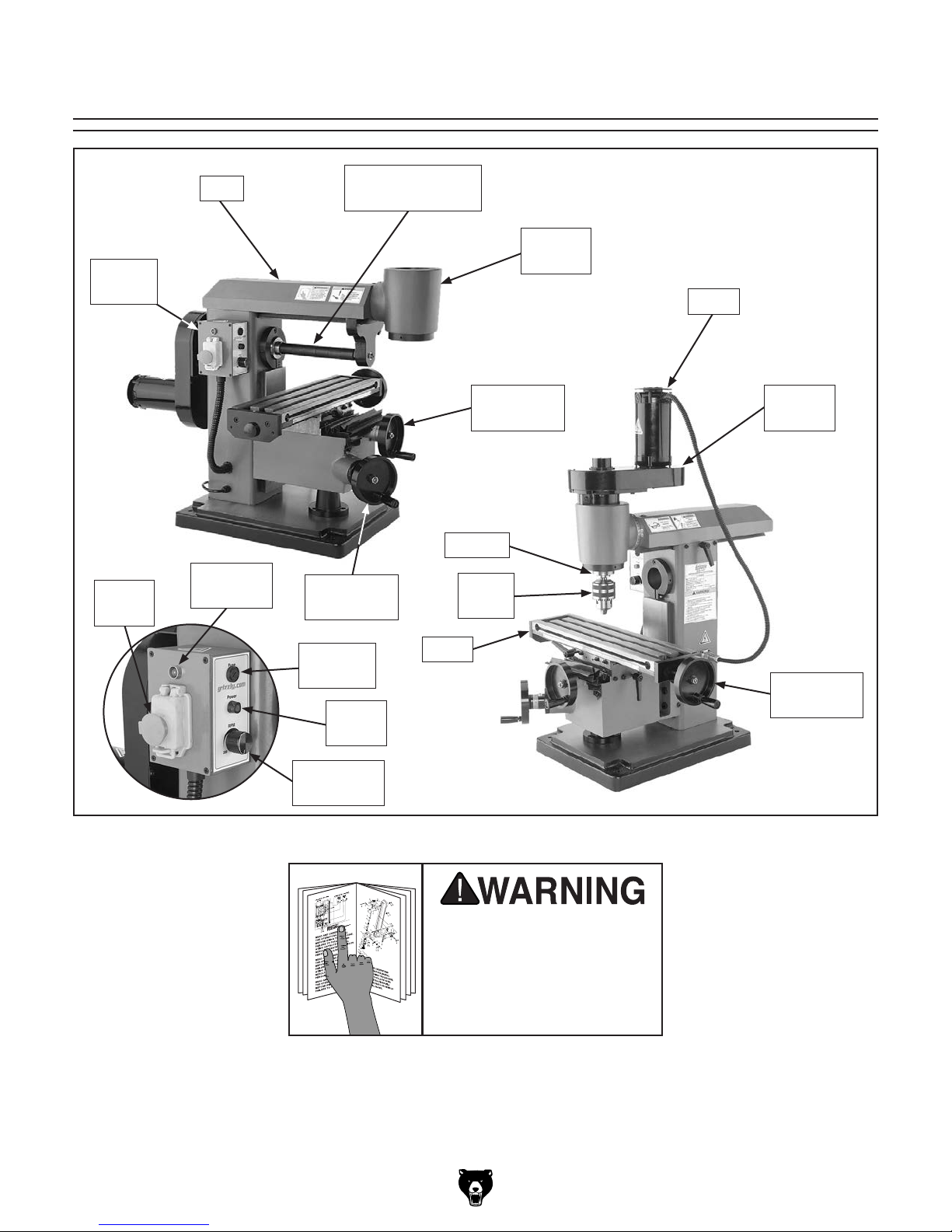
Identification
Control
Box
STOP
Button
Ram
Overload
Lamp
Horizontal Arbor
w/Spacers
Z-Axis
Handwheel
Y-Axis
Handwheel
Spindle
Drill
Chuck
Vertical
Head
Motor
Belt
Housing
Machine
Fuse
Power
Lamp
Spindle
Speed Dial
Figure 1. Model G0727 identification.
Table
To reduce the risk of
serious injury when using
this machine, read and
understand this entire
manual before beginning
any operations.
X-Axis
Handwheel
Model G0727 (Mfg. Since 7/11)
-3-

Machine Data Sheet
MACHINE DATA
SHEET
Customer Service #: (570) 546-9663 · To Order Call: (800) 523-4777 · Fax #: (800) 438-5901
MODEL G0727 MINI HORIZONTAL/VERTICAL MILL
Product Dimensions:
Weight............................................................................................................................................... Not Available lbs.
Width (side-to-side) x Depth (front-to-back) x Height...................................................... 23-7/16 x 29-1/8 x 23-1/2 in.
Footprint (Length x Width)............................................................................................................. 23-7/16 x 29-1/8 in.
Space Required for Full Range of Movement (Width x Depth).................................................................... 31 x 36 in.
Shipping Dimensions:
Type.......................................................................................................................................................... Wood Crate
Content........................................................................................................................................................... Machine
Weight.............................................................................................................................................................. 268 lbs.
Length x Width x Height....................................................................................................................... 28 x 35 x 30 in.
Electrical:
Power Requirement........................................................................................................... 110V, Single-Phase, 60 Hz
Prewired Voltage.................................................................................................................................................. 110V
Full-Load Current Rating....................................................................................................................................... 4.5A
Minimum Circuit Size.............................................................................................................................................. 15A
Connection Type....................................................................................................................................... Cord & Plug
Power Cord Included.............................................................................................................................................. Yes
Power Cord Length................................................................................................................................................. 6 ft.
Power Cord Gauge......................................................................................................................................... 18 AWG
Plug Included.......................................................................................................................................................... Yes
Included Plug Type................................................................................................................................................ 5-15
Switch Type........................................................................................... ON/OFF Push Button Switch w/Safety Cover
Motors:
Main
Type..................................................................................................................................................... Universal
Horsepower............................................................................................................................................. 1/2 HP
Phase............................................................................................................................................ Single-Phase
Amps........................................................................................................................................................... 4.5A
Speed.......................................................................................................................................... 0 – 5300 RPM
Power Transfer ................................................................................................................................. Gear Drive
Bearings..................................................................................................... Shielded & Permanently Lubricated
Main Specifications:
Operation Info
Max Distance Spindle to Column........................................................................................................ 12-7/8 in.
Max Distance Spindle to Table.............................................................................................................. 6-1/2 in.
Maximum Distance Horizontal Spindle Center to Table.............................................................................. 5 in.
Longitudinal Table Travel (X-Axis)...................................................................................................... 11-7/8 in.
Cross Table Travel (Y-Axis).............................................................................................................. 3-11/16 in.
Head Tilt (Left/Right).............................................................................................................................. 45 deg.
Drilling Capacity for Cast Iron................................................................................................................... 1/2 in.
End Milling Capacity............................................................................................................................. 21/32 in.
Face Milling Capacity.......................................................................................................................... 1-5/32 in.
-4-
Model G0727 (Mfg. Since 7/11)

Table Info
Table Length........................................................................................................................................ 18-1/8 in.
Table Width........................................................................................................................................... 4-3/4 in.
Table Thickness.................................................................................................................................... 1-5/8 in.
Number of T-Slots............................................................................................................................................ 3
T-Slot Size.............................................................................................................................................. 7/16 in.
T-Slots Centers...................................................................................................................................... 1-1/3 in.
X/Y-Axis Travel per Handwheel Revolution........................................................................................ 0.0625 in.
Z-Axis Travel per Handwheel Revolution......................................................................................... 0.03125 in.
Spindle Info
Spindle Taper............................................................................................................................................... R-8
Number of Vertical Spindle Speeds...................................................................................................... Variable
Range of Vertical Spindle Speeds........................................................................................... 200 – 2000 RPM
Quill Diameter........................................................................................................................................ 2-5/8 in.
Drawbar Thread Size............................................................................................................................. 7/16-20
Drawbar Length................................................................................................................................. 7-13/32 in.
Horizontal Spindle Sizes........................................................................................................................... 5/8 in.
Construction
Spindle Housing/Quill....................................................................... Chrome-Plated & Precision-Ground Steel
Table....................................................................................................................................... Ground Cast Iron
Column/Base....................................................................................................................................... Cast Iron
Base..................................................................................................................................................... Cast Iron
Paint Type/Finish.................................................................................................................................... Enamel
Other Specifications:
Country of Origin ................................................................................................................................................ China
Warranty ........................................................................................................................................................... 1 Year
Approximate Assembly & Setup Time ........................................................................................................ 30 Minutes
Serial Number Location ............................................................................................. ID Label on Center of the Stand
ISO 9001 Factory .................................................................................................................................................. Yes
Certified by a Nationally Recognized Testing Laboratory (NRTL) .......................................................................... No
Features:
Quick conversion from vertical milling to horizontal milling set up
Accessories Recommended:
H8177 Angle Work Table for Small Mills
H6195 3" Rotary Table w/ Clamps
T26485 58 pc. Clamping Kit for 7/16" T-Slots
H5685 4" Rotary Table w/ Clamps
T10253 2" Mini Self Centering Vise with Swivel Base
H7661 Quick Vise
G9511 T-Slot Nuts, pk. of 4, 7/16" Slot, 3/8" - 16
G1646 12 pc. Precision R-8 Collet Set
G5649 5-C Spin Index
H5621 R-8 Slitting Saw Arbor
Model G0727 (Mfg. Since 7/11)
-5-
SECTION 1: SAFETY
For Your Own Safety, Read Instruction
Manual Before Operating This Machine
The purpose of safety symbols is to attract your attention to possible hazardous conditions.
This manual uses a series of symbols and signal words intended to convey the level of importance of the safety messages. The progression of symbols is described below. Remember that
safety messages by themselves do not eliminate danger and are not a substitute for proper
accident prevention measures. Always use common sense and good judgment.
Indicates an imminently hazardous situation which, if not avoided,
WILL result in death or serious injury.
Indicates a potentially hazardous situation which, if not avoided,
COULD result in death or serious injury.
Indicates a potentially hazardous situation which, if not avoided,
MAY result in minor or moderate injury. It may also be used to alert
against unsafe practices.
This symbol is used to alert the user to useful information about
NOTICE
proper operation of the machine.
Safety Instructions for Machinery
OWNER’S MANUAL. Read and understand this
owner’s manual BEFORE using machine.
TRAINED OPERATORS ONLY. Untrained operators have a higher risk of being hurt or killed.
Only allow trained/supervised people to use this
machine. When machine is not being used, disconnect power, remove switch keys, or lock-out
machine to prevent unauthorized use—especially
around children. Make your workshop kid proof!
DANGEROUS ENVIRONMENTS. Do not use
machinery in areas that are wet, cluttered, or have
poor lighting. Operating machinery in these areas
greatly increases the risk of accidents and injury.
MENTAL ALERTNESS REQUIRED. Full mental
alertness is required for safe operation of machinery. Never operate under the influence of drugs or
alcohol, when tired, or when distracted.
ELECTRICAL EQUIPMENT INJURY RISKS. You
can be shocked, burned, or killed by touching live
electrical components or improperly grounded
machinery. To reduce this risk, only allow qualified
service personnel to do electrical installation or
repair work, and always disconnect power before
accessing or exposing electrical equipment.
DISCONNECT POWER FIRST.
nect machine from power supply BEFORE making
adjustments, changing tooling, or servicing machine.
This prevents an injury risk from unintended startup
or contact with live electrical components.
EYE PROTECTION. Always wear ANSI-approved
safety glasses or a face shield when operating or
observing machinery to reduce the risk of eye
injury or blindness from flying particles. Everyday
eyeglasses are NOT approved safety glasses.
Always discon-
-6-
Model G0727 (Mfg. Since 7/11)

WEARING PROPER APPAREL. Do not wear
clothing, apparel or jewelry that can become
entangled in moving parts. Always tie back or
cover long hair. Wear non-slip footwear to reduce
risk of slipping and losing control or accidentally
contacting cutting tool or moving parts.
HAZARDOUS DUST. Dust created by machinery
operations may cause cancer, birth defects, or
long-term respiratory damage. Be aware of dust
hazards associated with each workpiece material. Always wear a NIOSH-approved respirator to
reduce your risk.
HEARING PROTECTION. Always wear hearing protection when operating or observing loud
machinery. Extended exposure to this noise
without hearing protection can cause permanent
hearing loss.
REMOVE ADJUSTING TOOLS. Tools left on
machinery can become dangerous projectiles
upon startup. Never leave chuck keys, wrenches,
or any other tools on machine. Always verify
removal before starting!
USE CORRECT TOOL FOR THE JOB. Only use
this tool for its intended purpose—do not force
it or an attachment to do a job for which it was
not designed. Never make unapproved modifications—modifying tool or using it differently than
intended may result in malfunction or mechanical
failure that can lead to personal injury or death!
AWKWARD POSITIONS. Keep proper footing
and balance at all times when operating machine.
Do not overreach! Avoid awkward hand positions
that make workpiece control difficult or increase
the risk of accidental injury.
CHILDREN & BYSTANDERS. Keep children and
bystanders at a safe distance from the work area.
Stop using machine if they become a distraction.
GUARDS & COVERS. Guards and covers reduce
accidental contact with moving parts or flying
debris. Make sure they are properly installed,
undamaged, and working correctly BEFORE
operating machine.
FORCING MACHINERY. Do not force machine.
It will do the job safer and better at the rate for
which it was designed.
NEVER STAND ON MACHINE. Serious injury
may occur if machine is tipped or if the cutting
tool is unintentionally contacted.
STABLE MACHINE. Unexpected movement during operation greatly increases risk of injury or
loss of control. Before starting, verify machine is
stable and mobile base (if used) is locked.
USE RECOMMENDED ACCESSORIES. Consult
this owner’s manual or the manufacturer for recommended accessories. Using improper accessories will increase the risk of serious injury.
UNATTENDED OPERATION. To reduce the
risk of accidental injury, turn machine OFF and
ensure all moving parts completely stop before
walking away. Never leave machine running
while unattended.
MAINTAIN WITH CARE. Follow all maintenance
instructions and lubrication schedules to keep
machine in good working condition. A machine
that is improperly maintained could malfunction,
leading to serious personal injury or death.
DAMAGED PARTS. Regularly inspect machine
for damaged, loose, or mis-adjusted parts—or
any condition that could affect safe operation.
Immediately repair/replace BEFORE operating
machine. For your own safety, DO NOT operate
machine with damaged parts!
MAINTAIN POWER CORDS. When disconnecting cord-connected machines from power, grab
and pull the plug—NOT the cord. Pulling the cord
may damage the wires inside. Do not handle
cord/plug with wet hands. Avoid cord damage by
keeping it away from heated surfaces, high traffic
areas, harsh chemicals, and wet/damp locations.
EXPERIENCING DIFFICULTIES. If at any time
you experience difficulties performing the intended operation, stop using the machine! Contact our
Technical Support at (570) 546-9663.
Model G0727 (Mfg. Since 7/11)
-7-
Additional Safety for Mills
UNDERSTANDING CONTROLS. The mill is a
complex machine. To reduce the risk of injury,
make sure you understand the use and operation
of all controls before you begin milling.
SPINDLE SPEED. To avoid tool or workpiece
breakage that could send flying debris at the
operator and bystanders, use the correct spindle
speed and feed rate for the operation. Allow the
mill to gain full speed before beginning the cut.
STOPPING SPINDLE. Always allow the spindle
to stop on its own. To reduce the risk of lacerations, entanglement, or breakage debris, DO NOT
attempt to stop the spindle with your hand or a
tool.
SAFETY ACCESSORIES. Flying chips or debris
from the cutting operation can cause eye injury or
blindness. To reduce this risk, always use a face
shield in addition to your safety glasses when
milling.
WORK HOLDING. Attempting to mill a workpiece
that is not properly secured could cause breakage debris to fly at the operator. Before starting
the machine, be certain the workpiece has been
properly clamped to the table or secured in a vise.
NEVER hold the workpiece by hand during operation.
CH I P C L E AN U P. Waste chips created by the milling operation are sharp and hot and can cause
cuts or burns. Using compressed air to clear chips
could blow them into your eyes or drive them deep
into the working parts of the machine. Use a brush
or vacuum to clear away chips and debris from the
machine or workpiece. NEVER clear chips while
the spindle is turning.
MACHINE CARE & MAINTENANCE. Operating
the mill with excessively worn or damaged parts
increases the risk of accidents that could cause
serious injuries. A mill that is maintained poorly
will produce poor results. To reduce this risk,
maintain the mill in proper working condition by
ALWAYS promptly performing routine inspections
and maintenance.
CUTTING TOOL USAGE. Cutting tools have very
sharp leading edges—handle them with care!
Using cutting tools that are in good condition helps
to ensure quality results and reduces the risk of
personal injury from broken tool debris. Inspect
cutting tools for sharpness, chips, or cracks before
each use. ALWAYS make sure cutting tools are
firmly held in place before starting machine.
Like all machinery there is potential danger
when operating this machine. Accidents
are frequently caused by lack of familiarity
or failure to pay attention. Use this machine
with respect and caution to decrease the
risk of operator injury. If normal safety precautions are overlooked or ignored, serious personal injury may occur.
-8-
No list of safety guidelines can be complete. Every shop environment is different.
Always consider safety first, as it applies
to your individual working conditions. Use
this and other machinery with caution and
respect. Failure to do so could result in
serious personal injury, damage to equipment, or poor work results.
Model G0727 (Mfg. Since 7/11)
SECTION 2: POWER SUPPLY
Before installing the machine, consider the availability and proximity of the required power supply
circuit. If an existing circuit does not meet the
requirements for this machine, a new circuit must
be installed. To minimize the risk of electrocution,
fire, or equipment damage, installation work and
electrical wiring must be done by an electrican or
qualified service personnel in accordance with all
applicable codes and standards.
or equipment damage
may occur if machine is
not properly grounded
and connected to power
The full-load current rating is the amperage a
machine draws at 100% of the rated output power.
On machines with multiple motors, this is the
amperage drawn by the largest motor or sum of all
motors and electrical devices that might operate
at one time during normal operations.
The full-load current is not the maximum amount
of amps that the machine will draw. If the machine
is overloaded, it will draw additional amps beyond
the full-load rating.
If the machine is overloaded for a sufficient length
of time, damage, overheating, or fire may result—
especially if connected to an undersized circuit.
To reduce the risk of these hazards, avoid overloading the machine during operation and make
sure it is connected to a power supply circuit that
meets the specified circuit requirements.
For your own safety and protection of
Note: Circuit requirements in this manual apply to
a dedicated circuit—where only one machine will
be running on the circuit at a time. If machine will
be connected to a shared circuit where multiple
machines may be running at the same time, consult an electrician or qualified service personnel to
ensure circuit is properly sized for safe operation.
A power supply circuit includes all electrical
equipment between the breaker box or fuse panel
in the building and the machine. The power supply circuit used for this machine must be sized to
safely handle the full-load current drawn from the
machine for an extended period of time. (If this
machine is connected to a circuit protected by
fuses, use a time delay fuse marked D.)
This machine is prewired to operate on a power
supply circuit that has a verified ground and meets
the following requirements:
process. DO NOT connect to power until
Availability
Serious injury could occur if you connect
machine to power before completing setup
instructed later in this manual.
Circuit Requirements
Electrocution, fire, shock,
supply.
Full-Load Current Rating
Full-Load Current Rating at 110V .....4.5 Amps
Nominal Voltage ...............................110V/120V
Cycle .......................................................... 60 Hz
Phase ........................................... Single-Phase
Power Supply Circuit ......................... 15 Amps
property, consult an electrician if you are
unsure about wiring practices or electrical
codes in your area.
Model G0727 (Mfg. Since 7/11)
-9-
Improper connection of the equipment-grounding
wire can result in a risk of electric shock. The
wire with green insulation (with or without yellow
stripes) is the equipment-grounding wire. If repair
or replacement of the power cord or plug is necessary, do not connect the equipment-grounding
wire to a live (current carrying) terminal.
Check with a qualified electrician or service personnel if you do not understand these grounding
requirements, or if you are in doubt about whether
the tool is properly grounded. If you ever notice
that a cord or plug is damaged or worn, disconnect it from power, and immediately replace it with
a new one.
We do not recommend using an extension cord
with this machine.
cord, only use it if absolutely necessary and only
on a temporary basis.
Extension cords cause voltage drop, which can
damage electrical components and shorten motor
life. Voltage drop increases as the extension cord
size gets longer and the gauge size gets smaller
(higher gauge numbers indicate smaller sizes).
Any extension cord used with this machine must
be in good condition and contain a ground wire
and matching plug/receptacle. Additionally, it must
meet the following size requirements:
Grounding & Plug Requirements
Serious injury could occur if you connect
process. DO NOT connect to power until
it will not fit the outlet, have a qualified
electrician install the proper outlet with a
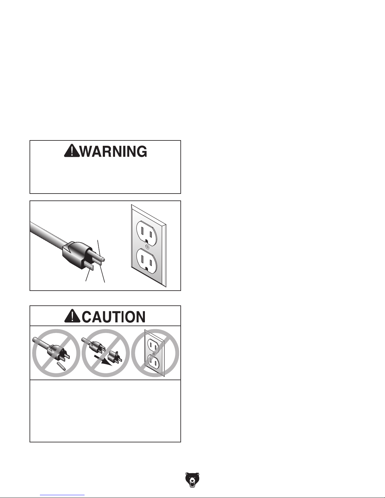
This machine MUST be grounded. In the event
of certain malfunctions or breakdowns, grounding
reduces the risk of electric shock by providing a
path of least resistance for electric current.
This machine is equipped with a power cord that
has an equipment-grounding wire and a grounding
plug. Only insert plug into a matching receptacle
(outlet) that is properly installed and grounded in
accordance with all local codes and ordinances.
DO NOT modify the provided plug!
machine to power before completing setup
instructed later in this manual.
GROUNDED
5-15 RECEPTACLE
Grounding Prong
5-15 PLUG
Neutral Hot
Figure 2. Typical 5-15 plug and receptacle.
Extension Cords
If you must use an extension
Minimum Gauge Size ...........................16 AWG
Maximum Length (Shorter is Better).......50 ft.
Two-prong outlets do not meet the grounding
requirements for this machine. Do not modify
or use an adapter on the plug provided—if
verified ground.
-10 -
SHOCK HAZARD!
Model G0727 (Mfg. Since 7/11)
SECTION 3: SETUP
This machine was carefully packaged for safe
transport. When unpacking, separate all enclosed
items from packaging materials and inspect them
for shipping damage.
,
please
IMPORTANT:
you are completely satisfied with the machine and
have resolved any issues between Grizzly or the
shipping agent. You MUST have the original pack-
aging to file a freight claim. It is also extremely
helpful if you need to return your machine later.
Keep children and pets away
from plastic bags or packing
materials shipped with this
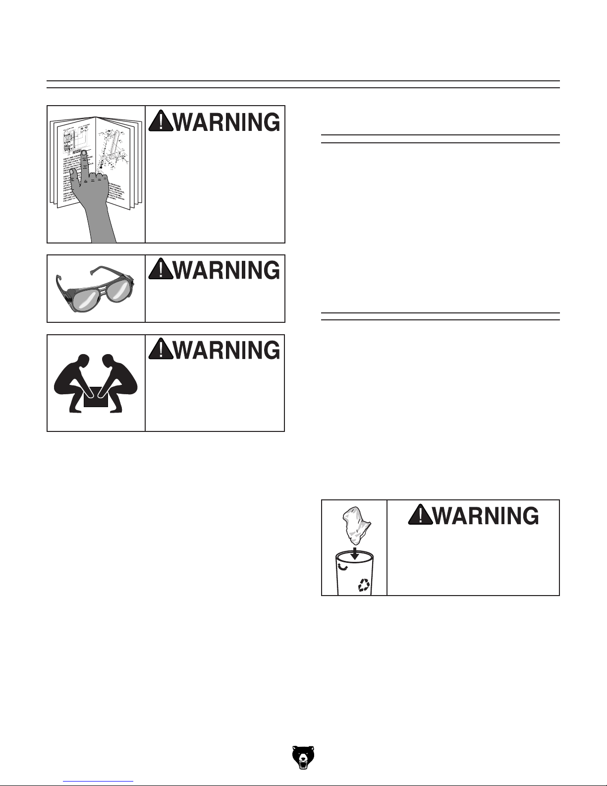
Needed for Setup
This machine presents
serious injury hazards
to untrained users. Read
through this entire manual to become familiar with
the controls and operations before starting the
machine!
Wear safety glasses during the entire setup process!
The following are needed to complete the setup
process, but are not included with your machine.
Description Qty
• Safety Glasses ........................................... 1
• Cleaner/Degreaser ..................... As Needed
• Disposable Shop Rags ............... As Needed
• Additional People for Lifting ....................... 2
Unpacking
This machine and its components are very heavy.
Get lifting help or use
power lifting equipment
to move heavy items.
If items are damaged
call us immediately at (570) 546-9663.
Save all packaging materials until
SUFFOCATION HAZARD!
machine. Discard immediately.
Model G0727 (Mfg. Since 7/11)
-11-
Inventory
The following is a list of items shipped with your
machine. Before beginning setup, lay these items
out and inventory them.
If any non-proprietary parts are missing (e.g. a
nut or a washer), we will gladly replace them; or
for the sake of expediency, replacements can be
obtained at your local hardware store.
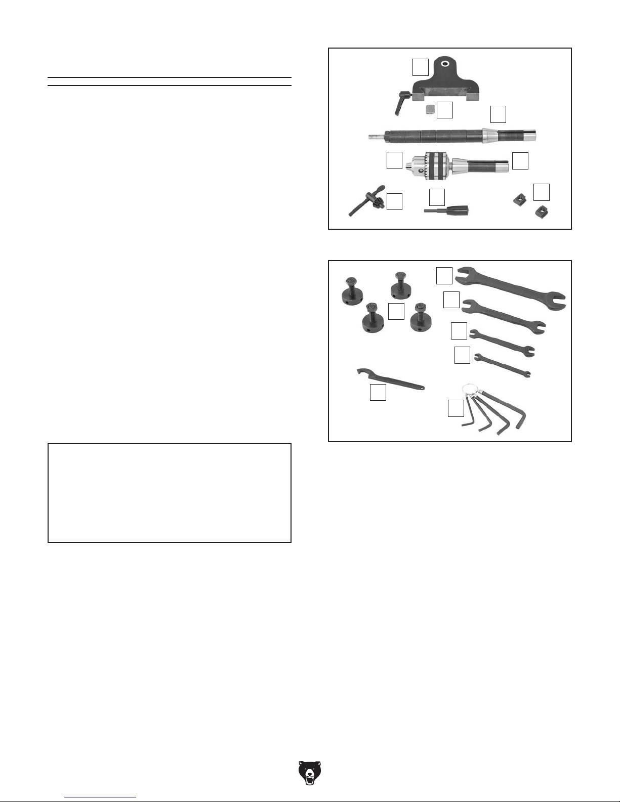
A
Small Item Inventory: (Figures 3–4) Qty
A. Horizontal Arbor Support Assembly ........... 1
B. Arbor Support Gib ...................................... 1
C. Horizontal Arbor w/Spacers ........................ 1
D. Chuck Arbor R8-JT33 ................................ 1
E. Drill Chuck JT33 1–13mm .......................... 1
F. Chuck Key .................................................. 1
G. Spindle Rod ................................................ 1
H. T- N uts M10 -1.5 ........................................... 2
I. Adjustable Foot Assemblies ....................... 4
J. Combo Wrench 21/24mm ........................... 1
K. Combo Wrench 14/17mm ........................... 1
L. Combo Wrench 12/10mm ........................... 1
M. Combo Wrench 5.5/7mm ........................... 1
N. Hex Wrench Set 3, 4, 5, 6mm ........... 1 Each
O. Spanner Wrench 22/26mm ........................ 1
B
E
F
Figure 3. Machine accessories.
I
O
G
J
K
L
M
N
C
D
H
NOTICE
If you cannot find an item on this list, carefully check around/inside the machine and
packaging materials. Often, these items get
lost in packaging materials while unpacking or they are pre-installed at the factory.
Figure 4. Tools and adjustable feet.
-12-
Model G0727 (Mfg. Since 7/11)
The unpainted surfaces of your machine are
coated with a heavy-duty rust preventative that
prevents corrosion during shipment and storage.
This rust preventative works extremely well, but it
will take a little time to clean.
Be patient and do a thorough job cleaning your
machine. The time you spend doing this now will
give you a better appreciation for the proper care
of your machine's unpainted surfaces.
There are many ways to remove this rust preventative, but the following steps work well in a wide
variety of situations. Always follow the manufacturer’s instructions with any cleaning product you
use and make sure you work in a well-ventilated
area to minimize exposure to toxic fumes.
Before cleaning, gather the following:
• Disposable rags
• Cleaner/degreaser (WD•40 works well)
• Safety glasses & disposable gloves
• Plastic paint scraper (optional)
Basic steps for removing rust preventative:
1.
2.
3.
4.
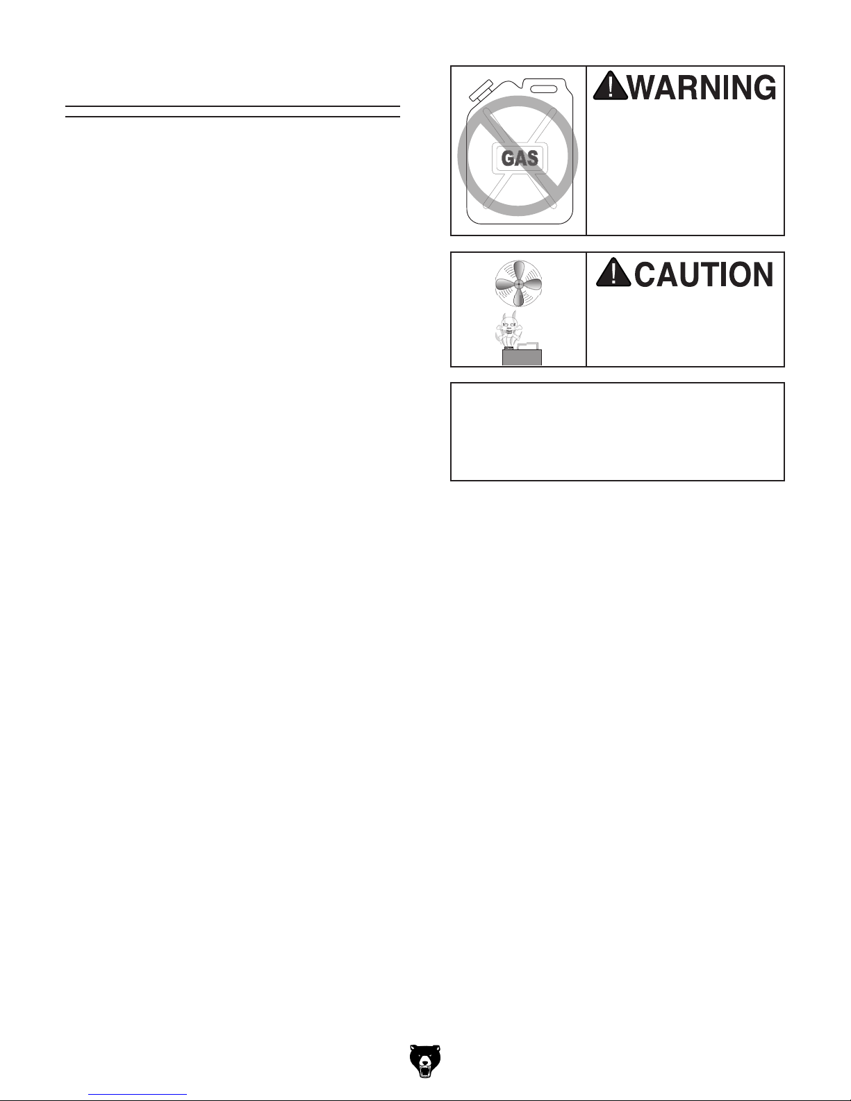
Many cleaning solvents
work in a well-ventilated
Avoid chlorine-based solvents, such as
Cleanup
Gasoline and petroleum
products have low flash
points and can explode
or cause fire if used to
clean machinery. Avoi d
using these products
to clean machinery.
Put on safety glasses.
Coat the rust preventative with a liberal
amount of cleaner/degreaser, then let it soak
for 5–10 minutes.
Wipe off the surfaces. If your cleaner/degreas-
er is effective, the rust preventative will wipe
off easily. If you have a plastic paint scraper,
scrape off as much as you can first, then wipe
off the rest with the rag.
are toxic if inhaled. Only
area.
NOTICE
acetone or brake parts cleaner, that may
damage painted surfaces.
Repeat Steps 2–3 as necessary until clean,
then coat all unpainted surfaces with a quality
metal protectant to prevent rust.
Model G0727 (Mfg. Since 7/11)
-13-
 Loading...