

Page 1
MODEL G0709
14" x 40" GUNSMITHING LATHE
OWNER'S MANUAL
(For models manufactured since 5/11)
COPYRIGHT © MAY, 2010 BY GRIZZLY INDUSTRIAL, INC., REVISED JUNE, 2012 (BL)
WARNING: NO PORTION OF THIS MANUAL MAY BE REPRODUCED IN ANY SHAPE
OR FORM WITHOUT THE WRITTEN APPROVAL OF GRIZZLY INDUSTRIAL, INC.
#CR12646 PRINTED IN CHINA
Page 2

This manual provides critical safety instructions on the proper setup,
operation, maintenance, and service of this machine/tool. Save this
document, refer to it often, and use it to instruct other operators.
Failure to read, understand and follow the instructions in this manual
may result in fire or serious personal injury—including amputation,
electrocution, or death.
The owner of this machine/tool is solely responsible for its safe use.
This responsibility includes but is not limited to proper installation in
a safe environment, personnel training and usage authorization,
proper inspection and maintenance, manual availability and comprehension, application of safety devices, cutting/sanding/grinding tool
integrity, and the usage of personal protective equipment.
The manufacturer will not be held liable for injury or property damage
from negligence, improper training, machine modifications or misuse.
Some dust created by power sanding, sawing, grinding, drilling, and
other construction activities contains chemicals known to the State
of California to cause cancer, birth defects or other reproductive
harm. Some examples of these chemicals are:
• Lead from lead-based paints.
• Crystalline silica from bricks, cement and other masonry products.
• Arsenic and chromium from chemically-treated lumber.
Your risk from these exposures varies, depending on how often you
do this type of work. To reduce your exposure to these chemicals:
Work in a well ventilated area, and work with approved safety equipment, such as those dust masks that are specially designed to filter
out microscopic particles.
Page 3

Table of Contents
INTRODUCTION ............................................... 2
Machine Description ...................................... 2
Contact Info.................................................... 2
Manual Accuracy ........................................... 2
Identification ................................................... 3
Machine Data Sheet ...................................... 4
SECTION 1: SAFETY ....................................... 7
Safety Instructions for Machinery .................. 7
Additional Safety for Metal Lathes ................. 9
Additional Chuck Safety ............................... 10
SECTION 2: POWER SUPPLY ...................... 11
SECTION 3: SETUP ....................................... 13
Preparation .................................................. 13
Unpacking .................................................... 13
Needed for Setup ......................................... 13
Inventory ...................................................... 14
Cleanup ........................................................ 15
Site Considerations ...................................... 16
Lifting & Moving ........................................... 17
Anchoring to Floor ....................................... 17
Leveling ........................................................ 18
Lubricating Lathe ......................................... 18
Adding Cutting Fluid .................................... 18
Power Connection........................................ 19
Test Run ...................................................... 19
Spindle Break-In .......................................... 22
Recommended Adjustments ........................ 22
SECTION 4: OPERATION .............................. 23
Operation Overview ..................................... 23
Controls ........................................................ 24
Chuck & Faceplate Removal/Installation ..... 27
Three-Jaw Chuck ......................................... 30
Four-Jaw Chuck ........................................... 31
Faceplate ..................................................... 32
Centers ........................................................ 33
Tailstock ....................................................... 35
Offsetting Tailstock ...................................... 35
Aligning Tailstock ......................................... 36
Drilling with Tailstock ................................... 37
Cutting Fluid System .................................... 39
Steady Rest & Follow Rest .......................... 39
Tool Post ...................................................... 40
Spider ........................................................... 41
Spindle Speed.............................................. 41
Manual Feed ................................................ 43
Power Feed.................................................. 43
Feed Settings ............................................... 44
Thread Settings............................................ 45
SECTION 5: ACCESSORIES ......................... 49
SECTION 6: MAINTENANCE ......................... 53
Schedule ...................................................... 53
Cleaning ....................................................... 53
Unpainted Cast Iron ..................................... 53
Ball Oiler Lubrication .................................... 54
Oil Reservoirs .............................................. 56
V-Belt Tension ............................................. 57
Cutting Fluid System .................................... 58
SECTION 7: SERVICE ................................... 59
Gib Adjustments........................................... 61
Backlash Adjustment ................................... 63
Half Nut Adjustment ..................................... 64
Leadscrew Endplay Adjustment .................. 64
Shear Pin Replacement ............................... 65
Feed Clutch Adjustment .............................. 66
Tailstock Lock .............................................. 67
Bearing Preload ........................................... 67
V-Belt Replacement ..................................... 70
Gap Insert Removal & Installation ............... 70
Brake Shoes ................................................ 72
Machine Storage .......................................... 73
SECTION 8: WIRING ...................................... 74
Wiring Safety Instructions ............................ 74
Wiring Overview ........................................... 75
Electrical Box Wiring .................................... 76
Switches and Pump Motor ........................... 77
Spindle Motor 110V & 220V Connection ..... 78
Electrical Box Photo ..................................... 79
SECTION 9: PARTS ....................................... 80
Headstock Case and Shift ........................... 80
Headstock Drive........................................... 82
Headstock Spindle ....................................... 84
Change Gears.............................................. 86
Quick Change Gearbox Drive ..................... 87
Quick Change Gearbox Shift ....................... 89
Apron .......................................................... 91
Cross Slide ................................................. 93
Compound Slide ......................................... 95
Rests ........................................................... 96
Tailstock ...................................................... 97
Pump ........................................................... 99
Motor and Feed Rod ................................. 100
Cabinet and Brake .................................... 102
Main Electrical Breakdown ........................ 104
Accessories ............................................... 105
Labels Breakdown ..................................... 106
WARRANTY AND RETURNS ...................... 109
Page 4
INTRODUCTION
We are proud to provide a high-quality owner’s
manual with your new machine!
We
instructions, specifications, drawings, and photographs
contained inside. Sometimes we make mistakes,
but
also
means that
you receive
will be slightly different than what is shown in
the manual
If you find this to be the case, and the difference
between the manual and machine leaves you
confused about a procedure
for an updated version. W
manuals
and
www.grizzly.com
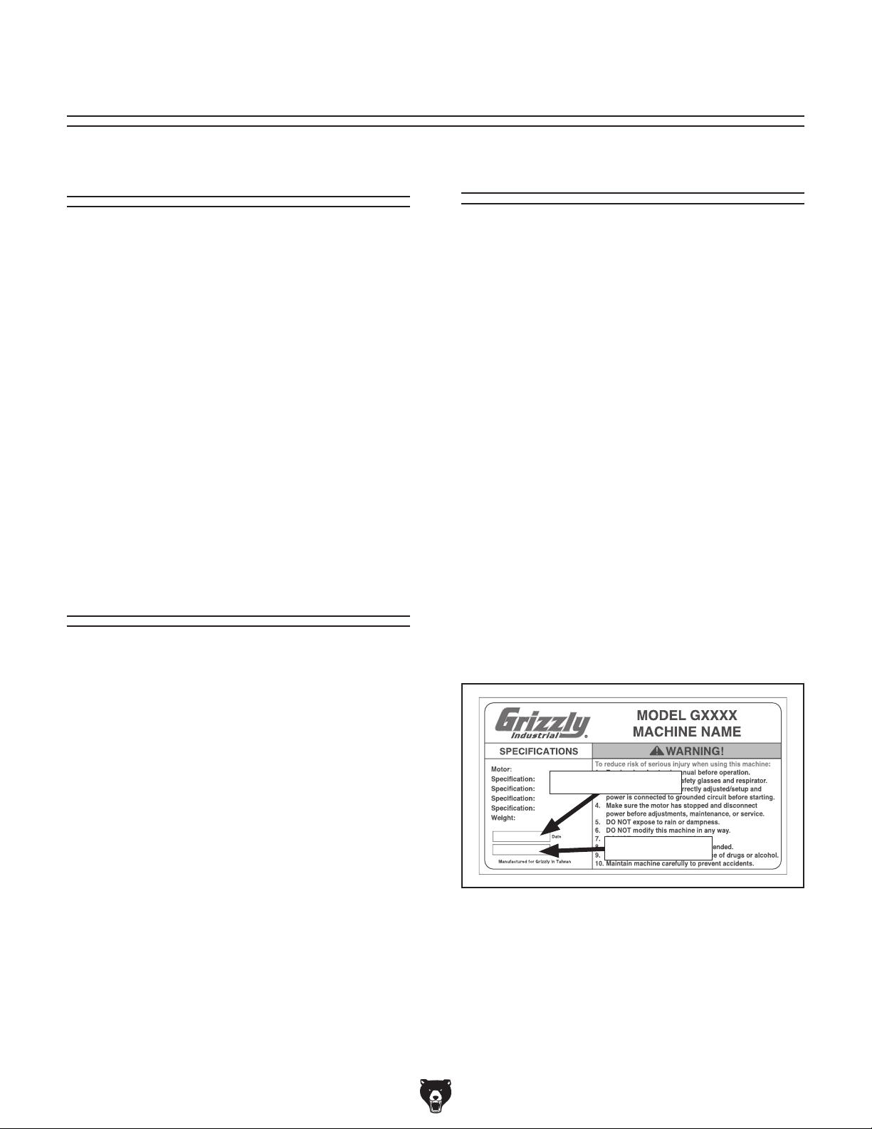
Alternatively, you can call our Technical Support
for help. Before calling, please write down the
Manufacture Date
stamped
into the machine ID label (see below). This information helps us determine if updated documentation is available for your machine.
We stand behind our machines. If you have
any questions or need help, use the information
below to contact us. Before contacting, please get
the serial number and manufacture date of your
machine. This will help us help you faster.
We want your feedback on this manual. What did
you like about it? Where could it be improved?
Please take a few minutes to give us feedback.
Email: manuals@grizzly.com
Machine Description
The purpose of a metal lathe is to face, turn, knurl,
thread, bore, or cut tapers in a metal workpiece
with perfect accuracy.
During typical operations, the lathe spindle rotates
the workpiece at various speeds against a fixed
cutting tool that is positioned at a particular angle
for the desired type of cut.
The cutting tool is mounted on a tool post, which
is positioned by three different slides that each
move in different directions.
Opposite of the headstock and spindle is a support device called a tailstock. The tailstock can
be slid along the lathe bed and locked in place to
firmly support the end of a workpiece.
Contact Info
Manual Accuracy
made every effort to be exact with the
our policy of continuous improvement
sometimes the machine
.
, check our website
e post current
manual updates for free on our website at
.
and Serial Number
Grizzly Technical Support
1203 Lycoming Mall Circle
Muncy, PA 17756
Phone: (570) 546-9663
Email: techsupport@grizzly.com
Grizzly Documentation Manager
P.O. Box 2069
Bellingham, WA 98227-2069
Manufacture Date
Serial Number
-2-
Model G0709 (Mfg. Since 5/11)
Page 5
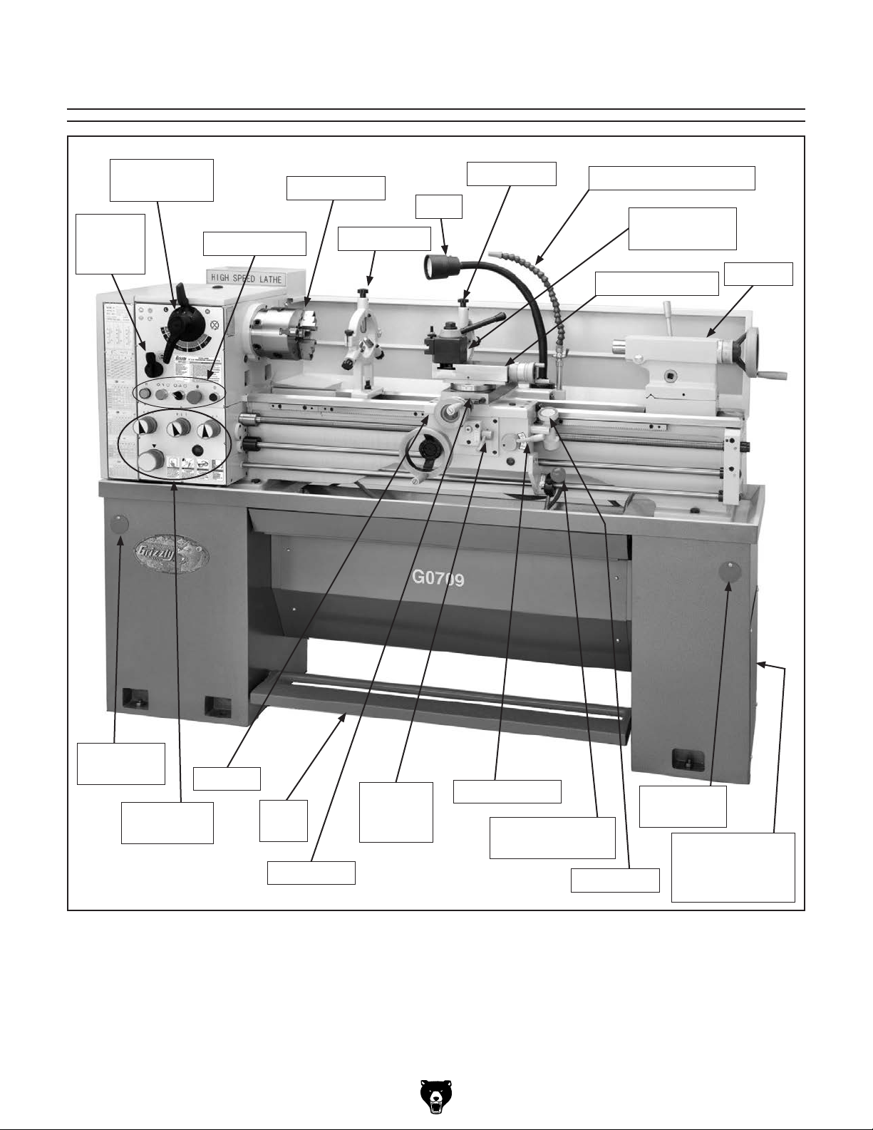
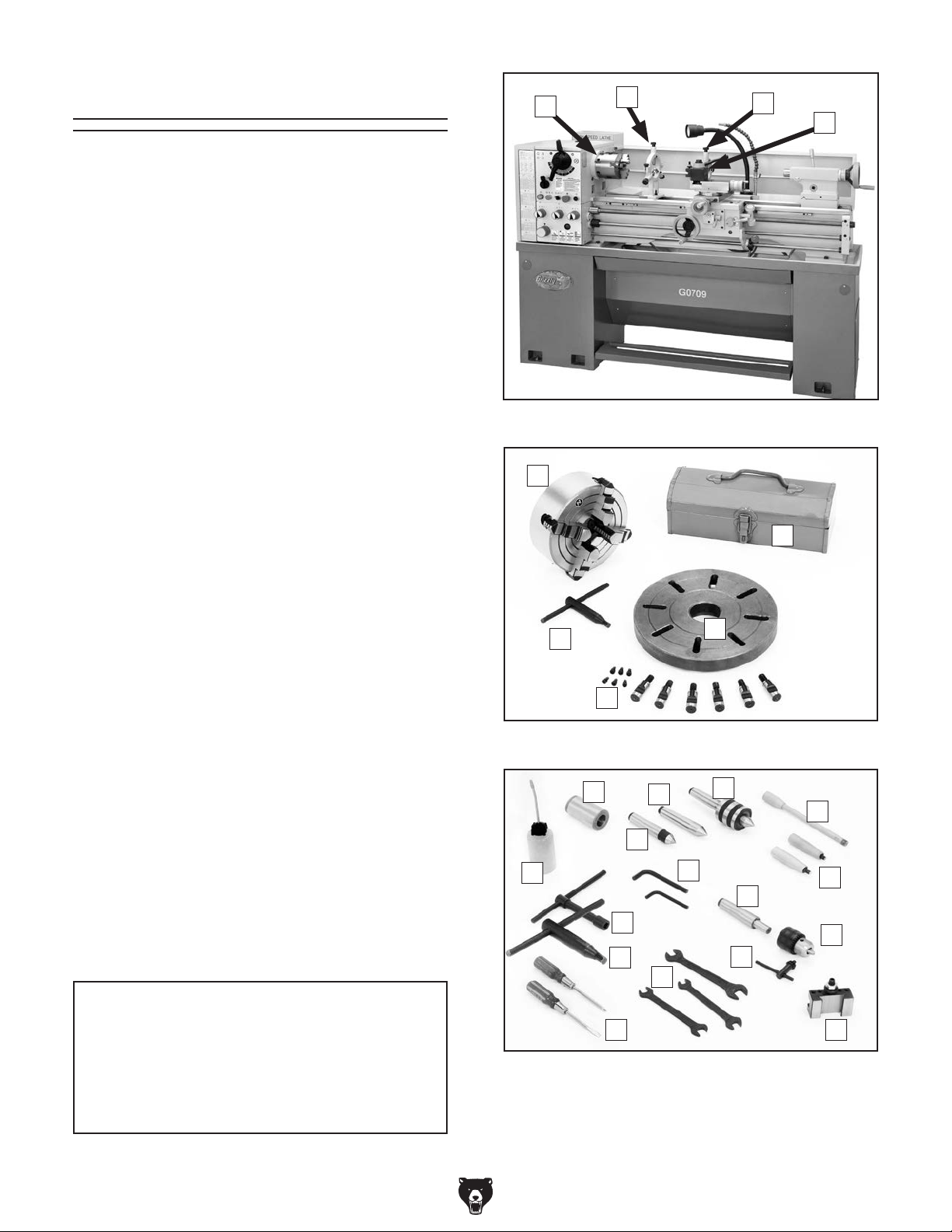
Identification
Speed Levers
Feed
Direction
Lever
Spindle
3-Jaw Chuck
Control Panel
Steady Rest
Light
Follow Rest
Cutting Fluid Nozzle
Quick Change
Tool Post
Compound Slide
Tailstock
Lifting Hole
w/Cover
Feed
Speed Dials
Model G0709 (Mfg. Since 5/11)
Carriage
Brake
Pedal
Cross Slide
Feed
Selection
Lever
Figure 1. Lathe features.
Half-Nut Lever
Spindle ON/OFF
Lever
Lifting Hole
Thread Dial
w/Cover
Fully Enclosed
Cutting Fluid
Pump and Tank
-3-
Page 6

Machine Data Sheet
MACHINE DATA
SHEET
Customer Service #: (570) 546-9663 · To Order Call: (800) 523-4777 · Fax #: (800) 438-5901
MODEL G0709 14 X 40 GUNSMITH'S GEARHEAD LATHE
Product Dimensions:
Weight............................................................................................................................................................ 1300 lbs.
Width (side-to-side) x Depth (front-to-back) x Height............................................................. 71-1/2 x 26-3/16 x 52 in.
Footprint (Length x Width)............................................................................................................... 70-3/8 x 15-3/4 in.
Shipping Dimensions:
Type.......................................................................................................................................................... Wood Crate
Content........................................................................................................................................................... Machine
Weight............................................................................................................................................................ 1550 lbs.
Length x Width x Height....................................................................................................................... 76 x 30 x 61 in.
Electrical:
Power Requirement........................................................................................................... 220V, Single-Phase, 60 Hz
Prewired Voltage.................................................................................................................................................. 220V
Full-Load Current Rating........................................................................................................................................ 10A
Minimum Circuit Size.............................................................................................................................................. 15A
Connection Type....................................................................................................................................... Cord & Plug
Power Cord Included............................................................................................................................................... No
Plug Included........................................................................................................................................................... No
Recommended Plug Type..................................................................................................................................... 6-15
Switch Type............................................................................................ Control Panel w/Magnetic Switch Protection
Motors:
Main
Type................................................................................................................. TEFC Capacitor-Start Induction
Horsepower................................................................................................................................................ 2 HP
Phase............................................................................................................................................ Single-Phase
Amps............................................................................................................................................................ 10A
Speed................................................................................................................................................ 1725 RPM
Power Transfer ............................................................................................................................... V-Belt Drive
Bearings..................................................................................................... Shielded & Permanently Lubricated
Main Specifications:
Operation Info
Swing Over Bed......................................................................................................................................... 14 in.
Distance Between Centers........................................................................................................................ 40 in.
Swing Over Cross Slide..................................................................................................................... 8-13/16 in.
Swing Over Saddle.......................................................................................................................... 13-13/16 in.
Swing Over Gap................................................................................................................................... 19.75 in.
Maximum Tool Bit Size............................................................................................................................. 5/8 in.
Compound Travel................................................................................................................................ 3-9/16 in.
Carriage Travel.......................................................................................................................................... 36 in.
Cross Slide Travel............................................................................................................................. 6-11/16 in.
-4-
Model G0709 (Mfg. Since 5/11)
Page 7

Headstock Info
Spindle Bore........................................................................................................................................... 1.57 in.
Spindle Taper............................................................................................................................................ MT#5
Number of Spindle Speeds............................................................................................................................... 8
Spindle Speeds......................................................................................................................... 70 – 2000 RPM
Spindle Type................................................................................................................................ D1-5 Camlock
Spindle Bearings................................................................................................................ NSK Tapered Roller
Spindle Length........................................................................................................................................... 17 in.
Spindle Length with 3-Jaw Chuck....................................................................................................... 21-7/8 in.
Spindle Length with 4-Jaw Chuck....................................................................................................... 21-1/4 in.
Spindle Length with Faceplate............................................................................................................ 18-1/2 in.
Tailstock Info
Tailstock Quill Travel......................................................................................................................... 3-15/16 in.
Tailstock Taper.......................................................................................................................................... MT#3
Tailstock Barrel Diameter..................................................................................................................... 1.656 in.
Threading Info
Number of Longitudinal Feeds....................................................................................................................... 24
Range of Longitudinal Feeds...................................................................................... 0.00168 – 0.1175 in./rev.
Number of Cross Feeds................................................................................................................................. 32
Range of Cross Feeds............................................................................................... 0.00046 – 0.03231 in./rev
Number of Inch Threads................................................................................................................................. 42
Range of Inch Threads.................................................................................................................... 4 – 112 TPI
Number of Metric Threads.............................................................................................................................. 44
Range of Metric Threads............................................................................................................... 0.1 – 7.0 mm
Number of Modular Pitches............................................................................................................................ 34
Range of Modular Pitches............................................................................................................ 0.1 – 1.75 MP
Number of Diametral Pitches.......................................................................................................................... 25
Range of Diametral Pitches............................................................................................................ 16 – 112 DP
Dimensions
Bed Width.............................................................................................................................................. 7-3/8 in.
Leadscrew Diameter................................................................................................................................. 7/8 in.
Leadscrew TPI........................................................................................................................................... 8 TPI
Leadscrew Length..................................................................................................................................... 50 in.
Steady Rest Capacity................................................................................................................... 3/8 – 2-3/4 in.
Follow Rest Capacity.................................................................................................................... 3/8 – 2-3/8 in.
Faceplate Size........................................................................................................................................... 11 in.
Feed Rod Diameter.................................................................................................................................. 3/4 in.
Floor to Center Height............................................................................................................................... 45 in.
Construction
Base..................................................................................................................................................... Cast Iron
Headstock............................................................................................................................................ Cast Iron
Headstock Gears............................................................................................................ Flame-Hardened Steel
Bed........................................................................................ Induction-Hardened, Precision-Ground Cast Iron
Body..................................................................................................................................................... Cast Iron
Stand.................................................................................................................................................... Cast Iron
Paint......................................................................................................................................................... Epoxy
Fluid Capacities
Headstock Capacity.................................................................................................................................. 4.2 qt.
Headstock Fluid Type................................................................ ISO 32 (eg. Grizzly T23963, Mobil DTE Light)
Gearbox Capacity..................................................................................................................................... 2.1 qt.
Gearbox Fluid Type...................................................................... ISO 68 (eg. Grizzly T23962, Mobil Vactra 2)
Apron Capacity............................................................................................................................................ 1 qt.
Apron Fluid Type.......................................................................... ISO 68 (eg. Grizzly T23962, Mobil Vactra 2)
Coolant Capacity....................................................................................................................................... 10 qt.
Model G0709 (Mfg. Since 5/11)
-5-
Page 8

Other Specifications:
Country Of Origin ............................................................................................................................................... China
Warranty ........................................................................................................................................................... 1 Year
Approximate Assembly & Setup Time .............................................................................................................. 1 Hour
Serial Number Location ..................................................................................................... ID Label on Front of Lathe
Sound Rating ..................................................................................................................................................... 82 dB
ISO 9001 Factory .................................................................................................................................................... No
CSA Certified .......................................................................................................................................................... No
Features:
NSK precision tapered roller spindle bearings
Flame hardened headstock gears
Induction-hardened and precision ground cast iron bed
Coolant system
Adjustable halogen work light
Foot brake with motor shut-off switch
Full-length splash guard
Pull-out chip tray
200-Series quick-change tool post
Outboard spindle spider mount with 4 brass-tipped screws
Cast iron cabinet stands
Fully-enclosed quick-change gearbox
Tailstock offset V-slide with wrench locking socket
D1-5 Camlock Spindle
Accessories Included:
6" 3-Jaw chuck with reversible jaws
8" 4-Jaw chuck with independent jaws
11" Faceplate
MT#3 live center
Standard MT#3 dead center
Carbide-tipped MT#3 dead center
MT#5-MT#3 sleeve
1/2" Drill chuck with MT#3 arbor
Tailstock wrench
Service tools
Toolbox
-6-
Model G0709 (Mfg. Since 5/11)
Page 9

SECTION 1: SAFETY
For Your Own Safety, Read Instruction
Manual Before Operating This Machine
The purpose of safety symbols is to attract your attention to possible hazardous conditions.
This manual uses a series of symbols and signal words intended to convey the level of importance of the safety messages. The progression of symbols is described below. Remember that
safety messages by themselves do not eliminate danger and are not a substitute for proper
accident prevention measures. Always use common sense and good judgment.
Indicates an imminently hazardous situation which, if not avoided,
WILL result in death or serious injury.
Indicates a potentially hazardous situation which, if not avoided,
COULD result in death or serious injury.
Indicates a potentially hazardous situation which, if not avoided,
MAY result in minor or moderate injury. It may also be used to alert
against unsafe practices.
This symbol is used to alert the user to useful information about
NOTICE
proper operation of the machine.
Safety Instructions for Machinery
OWNER’S MANUAL. Read and understand this
owner’s manual BEFORE using machine.
TRAINED OPERATORS ONLY. Untrained operators have a higher risk of being hurt or killed.
Only allow trained/supervised people to use this
machine. When machine is not being used, disconnect power, remove switch keys, or lock-out
machine to prevent unauthorized use—especially
around children. Make workshop kid proof!
DANGEROUS ENVIRONMENTS. Do not use
machinery in areas that are wet, cluttered, or have
poor lighting. Operating machinery in these areas
greatly increases the risk of accidents and injury.
MENTAL ALERTNESS REQUIRED. Full mental
alertness is required for safe operation of machinery. Never operate under the influence of drugs or
alcohol, when tired, or when distracted.
ELECTRICAL EQUIPMENT INJURY RISKS. You
can be shocked, burned, or killed by touching live
electrical components or improperly grounded
machinery. To reduce this risk, only allow qualified
service personnel to do electrical installation or
repair work, and always disconnect power before
accessing or exposing electrical equipment.
DISCONNECT POWER FIRST.
nect machine from power supply BEFORE making
adjustments, changing tooling, or servicing machine.
This prevents an injury risk from unintended startup
or contact with live electrical components.
EYE PROTECTION. Always wear ANSI-approved
safety glasses or a face shield when operating or
observing machinery to reduce the risk of eye
injury or blindness from flying particles. Everyday
eyeglasses are NOT approved safety glasses.
Always discon-
Model G0709 (Mfg. Since 5/11)
-7-
Page 10

WEARING PROPER APPAREL. Do not wear
clothing, apparel or jewelry that can become
entangled in moving parts. Always tie back or
cover long hair. Wear non-slip footwear to avoid
accidental slips, which could cause loss of workpiece control.
HAZARDOUS DUST. Dust created while using
machinery may cause cancer, birth defects, or
long-term respiratory damage. Be aware of dust
hazards associated with each workpiece material,
and always wear a NIOSH-approved respirator to
reduce your risk.
HEARING PROTECTION. Always wear hearing protection when operating or observing loud
machinery. Extended exposure to this noise
without hearing protection can cause permanent
hearing loss.
REMOVE ADJUSTING TOOLS. Tools left on
machinery can become dangerous projectiles
upon startup. Never leave chuck keys, wrenches,
or any other tools on machine. Always verify
removal before starting!
USE CORRECT TOOL FOR THE JOB. Only use
this tool for its intended purpose—do not force
it or an attachment to do a job for which it was
not designed. Never make unapproved modifications—modifying tool or using it differently than
intended may result in malfunction or mechanical
failure that can lead to personal injury or death!
AWKWARD POSITIONS. Keep proper footing
and balance at all times when operating machine.
Do not overreach! Avoid awkward hand positions
that make workpiece control difficult or increase
the risk of accidental injury.
CHILDREN & BYSTANDERS. Keep children and
bystanders at a safe distance from the work area.
Stop using machine if they become a distraction.
FORCING MACHINERY. Do not force machine.
It will do the job safer and better at the rate for
which it was designed.
NEVER STAND ON MACHINE. Serious injury
may occur if machine is tipped or if the cutting
tool is unintentionally contacted.
STABLE MACHINE. Unexpected movement during operation greatly increases risk of injury or
loss of control. Before starting, verify machine is
stable and mobile base (if used) is locked.
USE RECOMMENDED ACCESSORIES. Consult
this owner’s manual or the manufacturer for recommended accessories. Using improper accessories will increase the risk of serious injury.
UNATTENDED OPERATION. To reduce the
risk of accidental injury, turn machine OFF and
ensure all moving parts completely stop before
walking away. Never leave machine running
while unattended.
MAINTAIN WITH CARE. Follow all maintenance
instructions and lubrication schedules to keep
machine in good working condition. A machine
that is improperly maintained could malfunction,
leading to serious personal injury or death.
CHECK DAMAGED PARTS. Regularly inspect
machine for any condition that may affect safe
operation. Immediately repair or replace damaged
or mis-adjusted parts before operating machine.
MAINTAIN POWER CORDS. When disconnecting cord-connected machines from power, grab
and pull the plug—NOT the cord. Pulling the cord
may damage the wires inside. Do not handle
cord/plug with wet hands. Avoid cord damage by
keeping it away from heated surfaces, high traffic
areas, harsh chemicals, and wet/damp locations.
GUARDS & COVERS. Guards and covers reduce
accidental contact with moving parts or flying
debris. Make sure they are properly installed,
undamaged, and working correctly.
-8-
EXPERIENCING DIFFICULTIES. If at any time
you experience difficulties performing the intended operation, stop using the machine! Contact our
Technical Support at (570) 546-9663.
Model G0709 (Mfg. Since 5/11)
Page 11

Additional Safety for Metal Lathes
Never attempt to slow or stop the lathe spindle with
SPEED RATES. Operating the lathe at the wrong
speed can cause nearby parts to break or the
workpiece to come loose, which will result in dangerous projectiles that could cause severe impact
injuries. Large or non-concentric workpieces must
be turned at slow speeds. Always use the appropriate feed and speed rates.
CHUCK KEY SAFETY. A chuck key left in the
chuck can become a deadly projectile when the
spindle is started. Always remove the chuck key
after using it. Develop a habit of not taking your
hand off of a chuck key unless it is away from the
machine.
SAFE CLEARANCES. Workpieces that crash
into other components on the lathe may throw
dangerous projectiles in all directions, leading to
impact injury and damaged equipment. Before
starting the spindle, make sure the workpiece has
adequate clearance by hand-rotating it through its
entire range of motion. Also, check the tool and
tool post clearance, chuck clearance, and saddle
clearance.
LONG STOCK SAFETY. Long stock can whip
violently if not properly supported, causing serious
impact injury and damage to the lathe. Reduce this
risk by supporting any stock that extends from the
chuck/headstock more than three times its own
diameter. Always turn long stock at slow speeds.
SECURING WORKPIECE. An improperly secured
workpiece can fly off the lathe spindle with deadly
force, which can result in a severe impact injury.
Make sure the workpiece is properly secured in the
chuck or faceplate before starting the lathe.
CHUCKS. Chucks are very heavy and difficult to
grasp, which can lead to crushed fingers or hands
if mishandled. Get assistance when handling
chucks to reduce this risk. Protect your hands and
the precision-ground ways by using a chuck cradle
or piece of plywood over the ways of the lathe
when servicing chucks. Use lifting devices when
necessary.
CLEARING CHIPS. Metal chips can easily cut
bare skin—even through a piece of cloth. Avoid
clearing chips by hand or with a rag. Use a brush
or vacuum to clear metal chips.
STOPPING SPINDLE BY HAND. Stopping the
spindle by putting your hand on the workpiece
or chuck creates an extreme risk of entanglement, impact, crushing, friction, or cutting hazards.
your hand. Allow the spindle to come to a stop on
its own or use the brake.
CRASHES. Aggressively driving the cutting tool or
other lathe components into the chuck may cause
an explosion of metal fragments, which can result
in severe impact injuries and major damage to
the lathe. Reduce this risk by releasing automatic
feeds after use, not leaving lathe unattended, and
checking clearances before starting the lathe.
Make sure no part of the tool, tool holder, compound rest, cross slide, or carriage will contact the
chuck during operation.
COOLANT SAFETY. Coolant is a very poisonous biohazard that can cause personal injury from
skin contact alone. Incorrectly positioned coolant
nozzles can splash on the operator or the floor,
resulting in an exposure or slipping hazard. To
decrease your risk, change coolant regularly and
position the nozzle where it will not splash or end
up on the floor.
TOOL SELECTION. Cutting with an incorrect or
dull tool increases the risk of accidental injury due
to the extra force required for the operation, which
increases the risk of breaking or dislodging components that can cause small shards of metal to
become dangerous projectiles. Always select the
right cutter for the job and make sure it is sharp. A
correct, sharp tool decreases strain and provides
a better finish.
Model G0709 (Mfg. Since 5/11)
-9-
Page 12

Additional Chuck Safety
ENTANGLEMENT. Entanglement with a rotat-
ing chuck can lead to death, amputation, broken
bones, or other serious injury. Never attempt to
slow or stop the lathe chuck by hand, and always
roll up long sleeves, tie back long hair, and remove
any jewelry or loose apparel BEFORE operating.
CHUCK SPEED RATING. Excessive spindle
speeds greatly increase the risk of the workpiece
or chuck being thrown from the machine with
deadly force. Never use spindle speeds faster than
the chuck RPM rating or the safe limits of your
workpiece.
USING CORRECT EQUIPMENT. Many workpieces can only be safely turned in a lathe if additional
support equipment, such as a tailstock or steady/
follow rest, is used. If the operation is too hazardous to be completed with the lathe or existing
equipment, the operator must have enough experience to know when to use a different machine or
find a safer way.
TRAINED OPERATORS ONLY. Using a chuck
incorrectly can result in workpieces coming loose
at high speeds and striking the operator or bystanders with deadly force. To reduce the risk of this hazard, read and understand this document and seek
additional training from an experienced chuck user
before using a chuck.
CHUCK CAPACITY. Avoid exceeding the capacity
of the chuck by clamping an oversized workpiece.
If the workpiece is too large to safely clamp with
the chuck, use a faceplate or a larger chuck if possible. Otherwise, the workpiece could be thrown
from the lathe during operation, resulting in serious
impact injury or death.
CLAMPING FORCE. Inadequate clamping force
can lead to the workpiece being thrown from the
chuck and striking the operator or bystanders.
Maximum clamping force is achieved when the
chuck is properly maintained and lubricated, all
jaws are fully engaged with the workpiece, and
the maximum chuck clamping diameter is not
exceeded.
PROPER MAINTENANCE. All chucks must be
properly maintained and lubricated to achieve
maximum clamping force and withstand the rigors
of centrifugal force. To reduce the risk of a thrown
workpiece, follow all maintenance intervals and
instructions in this document.
DISCONNECT POWER. Serious entanglement or
impact injuries could occur if the lathe is started
while you are adjusting, servicing, or installing the
chuck. Always disconnect the lathe from power
before performing these procedures.
-10 -
Model G0709 (Mfg. Since 5/11)
Page 13

SECTION 2: POWER SUPPLY
Before installing the machine, consider the availability and proximity of the required power supply
circuit. If an existing circuit does not meet the
requirements for this machine, a new circuit must
be installed. To minimize the risk of electrocution,
fire, or equipment damage, installation work and
electrical wiring must be done by an electrican or
qualified service personnel in accordance with all
applicable codes and standards.
Electrocution, fire, or
equipment damage may
occur if machine is not
correctly grounded and
connected to the power
The full-load current rating is the amperage a
machine draws at 100% of the rated output power.
On machines with multiple motors, this is the
amperage drawn by the largest motor or sum of all
motors and electrical devices that might operate
at one time during normal operations.
The full-load current is not the maximum amount
of amps that the machine will draw. If the machine
is overloaded, it will draw additional amps beyond
the full-load rating.
If the machine is overloaded for a sufficient length
of time, damage, overheating, or fire may result—
especially if connected to an undersized circuit.
To reduce the risk of these hazards, avoid overloading the machine during operation and make
sure it is connected to a power supply circuit that
meets the requirements in the following section.
This machine is prewired to operate on a 220V
power supply circuit that has a verified ground and
meets the following requirements:
For your own safety and protection of
Note: The circuit requirements listed in this manual apply to a dedicated circuit—where only one
machine will be running at a time. If this machine
will be connected to a shared circuit where multiple machines will be running at the same time,
consult a qualified electrician to ensure that the
circuit is properly sized for safe operation.
A power supply circuit includes all electrical
equipment between the breaker box or fuse panel
in the building and the machine. The power supply circuit used for this machine must be sized to
safely handle the full-load current drawn from the
machine for an extended period of time. (If this
machine is connected to a circuit protected by
fuses, use a time delay fuse marked D.)
Availability
supply.
Full-Load Current Rating
Circuit Requirements for 220V
Nominal Voltage .............................. 220V/ 240V
Cycle .......................................................... 60 Hz
Phase .................................................... 1-Phase
Circuit Rating ...................................... 15 Amps
Plug/Receptacle ............................. NEMA 6-15
Cord ......... 3-Wire, 14 AWG, 300VAC, “S”-Type
Full-Load Current Rating at 220V ..... 10 Amps
Model G0709 (Mfg. Since 5/11)
property, consult an electrician if you are
unsure about wiring practices or electrical
codes in your area.
-11-
Page 14
We do not recommend using an extension cord
with this machine.
cord, only use it if absolutely necessary and only
on a temporary basis.
Extension cords cause voltage drop, which may
damage electrical components and shorten motor
life. Voltage drop increases as the extension cord
size gets longer and the gauge size gets smaller
(higher gauge numbers indicate smaller sizes).
Any extension cord used with this machine must
contain a ground wire, match the required plug
and receptacle, and meet the following requirements:
Grounding Instructions
This machine MUST be grounded. In the event
of certain malfunctions or breakdowns, grounding
reduces the risk of electric shock by providing a
path of least resistance for electric current.
Improper connection of the equipment-grounding
wire can result in a risk of electric shock. The
wire with green insulation (with or without yellow
stripes) is the equipment-grounding wire. If repair
or replacement of the power cord or plug is necessary, do not connect the equipment-grounding
wire to a live (current carrying) terminal.
Check with a qualified electrician or service personnel if you do not understand these grounding
requirements, or if you are in doubt about whether
the tool is properly grounded. If you ever notice
that a cord or plug is damaged or worn, disconnect it from power, and immediately replace it with
a new one.
Serious injury could occur if you connect
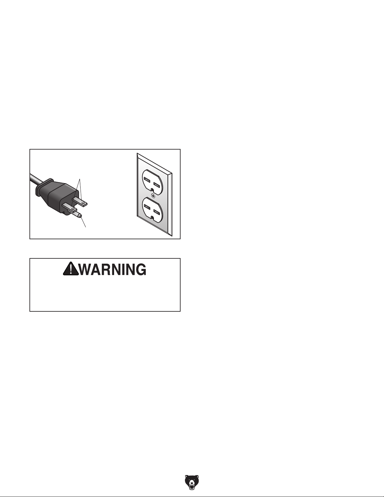
The power cord and plug specified under “Circuit
Requirements for 220V”
has an equipment-grounding wire and a grounding prong. The plug must only be inserted into
a matching receptacle (outlet) that is properly
installed and grounded in accordance with all
local codes and ordinances (see figure below).
on the previous page
GROUNDED
6-15 RECEPTACLE
Current Carrying Prongs
6-15 PLUG
Extension Cords
If you must use an extension
Grounding Prong
Figure 2. NEMA 6 -15 plug and receptacle.
the machine to power before completing the
setup process. DO NOT connect to power
until instructed later in this manual.
-12-
Minimum Gauge Size ...........................14 AWG
Maximum Length (Shorter is Better).......50 ft.
Model G0709 (Mfg. Since 5/11)
Page 15

SECTION 3: SETUP
Your machine was carefully packaged for safe
transportation. Remove the packaging materials
from around your machine and inspect it. If you
discover any damage, please call us immediately
at (570) 546-9663
Save the containers and all packing materials for
possible inspection by the carrier or its agent.
Otherwise, filing a freight claim can be difficult.
When you are completely satisfied with the condition of your shipment, inventory the contents.
Keep children and pets away
from plastic bags or packing
materials shipped with this
Preparation
The list below outlines the basic process of preparing your machine for operation. Specific steps
are covered later in this section.
The typical preparation process is as follows:
1. Unpack the lathe and inventory the contents
of the box/crate.
2. Clean the lathe and its components.
3. Identify an acceptable location for the lathe
and move it to that location.
4. Level the lathe and bolt it to the floor.
5. Assemble the loose components and make
any necessary adjustments or inspections to
ensure the lathe is ready for operation.
6. Check lathe for proper lubrication.
Unpacking
for advice.
SUFFOCATION HAZARD!
machine. Discard immediately.
7. Connect the lathe to the power source.
8. Test run lathe to ensure it functions properly.
9. Perform the spindle break-in procedure to
prepare the lathe for operation.
Model G0709 (Mfg. Since 5/11)
Needed for Setup
The following are needed to complete the setup
process, but are not included with your machine.
Description Qty
• Forklift or Hoist (Rated 2000 lbs.) .............. 1
• Lifting Straps (Rated 2000 lbs.) .................. 2
• Lifting Hooks (Rated 2000 lbs.) .................. 2
• Machinist's Level ........................................ 1
• Degreaser/Solvent Cleaner ......... as needed
• Shop Rags for Cleaning .............. as needed
• Stiff Brush for Cleaning .............................. 1
-13-
Page 16
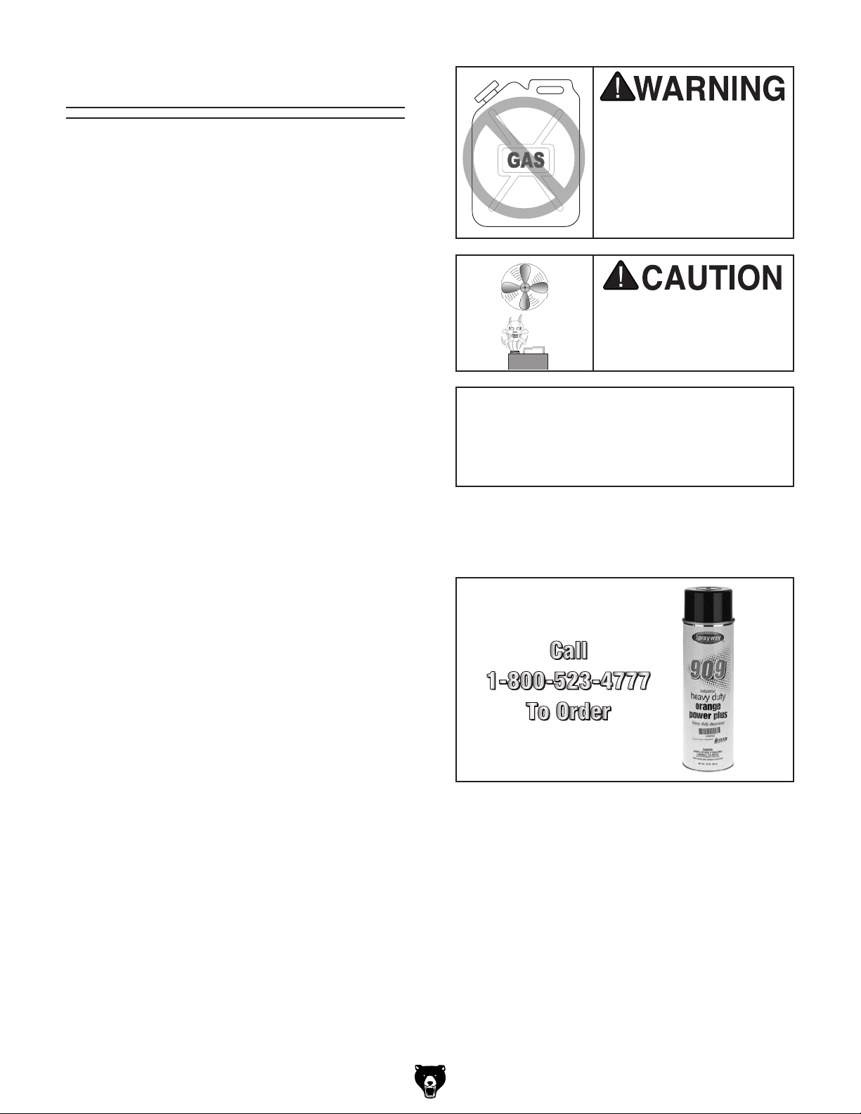
Inventory
The following is a list of items shipped with your
machine. Before beginning setup, lay these items
out and inventory them.
If any non-proprietary parts are missing (e.g. a
nut or a washer), we will gladly replace them; or
for the sake of expediency, replacements can be
obtained at your local hardware store.
Mounted Inventory Components Qty
A. Three-Jaw Chuck 6" ................................... 1
B. Steady Rest ................................................ 1
C. Follow Rest ................................................. 1
D. Quick Change Tool Post w/Holder ............. 1
A
Figure 3. Mounted inventory components.
B
C
D
Loose Inventory Components Qty
E. Four-Jaw Chuck 8" ..................................... 1
F. Toolbox ....................................................... 1
G. Four-Jaw Chuck Wrench ............................ 1
H. Faceplate 11" .............................................. 1
I. Faceplate Camlock Set .............................. 1
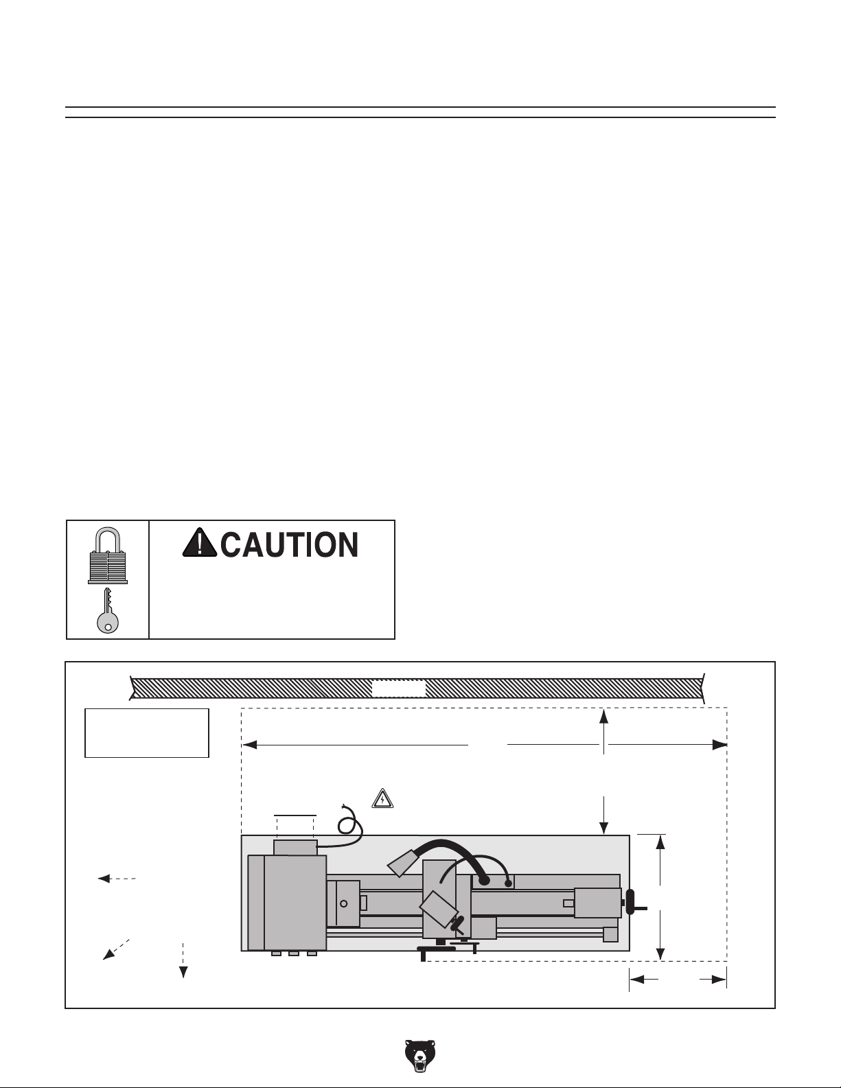
Toolbox Inventory Components Qty
J. Bottle for Oil ............................................... 1
K. Spindle Sleeve MT#5/MT#3 ....................... 1
L. Dead Center MT#3 Carbide Tip ................. 1
M. Dead Center MT#3 HSS Tip ...................... 1
N. Live Center MT#3 ....................................... 1
O. Tailstock Lock Lever ................................... 1
P. Handles ...................................................... 2
Q. Chuck Arbor MT#3/JT3 ............................. 1
R. Hex Wrench Set 6, 8mm ...................1 Each
S. "T" Wrench ................................................. 1
T. Three-Jaw Chuck Key ................................ 1
U. Phillips and Standard Screwdriver #2 ........ 1
V. Open-End Wrench Set
9/11, 10/12, 12/14mm .........................1 Each
W. Drill Chuck Key ........................................... 1
X. Drill Chuck
Y. Tool Holder (One Installed) ........................ 2
1
⁄2 "-JT3 .................................... 1
E
F
G
I
Figure 4. Loose inventory components.
K
J
M
L
S
T
V
H
N
R
Q
W
O
P
X
NOTICE
If you cannot find an item on this list, carefully check around/inside the machine and
packaging materials. Often, these items get
lost in packaging materials while unpacking or they are pre-installed at the factory.
-14-
U
Figure 5. Toolbox inventory.
Model G0709 (Mfg. Since 5/11)
Y
Page 17
The unpainted surfaces of your machine are
coated with a heavy-duty rust preventative that
prevents corrosion during shipment and storage.
This rust preventative works extremely well, but it
will take a little time to clean.
Be patient and do a thorough job cleaning your
machine. The time you spend doing this now will
give you a better appreciation for the proper care
of your machine's unpainted surfaces.
There are many ways to remove this rust preventative, but the following steps work well in a wide
variety of situations. Always follow the manufacturer’s instructions with any cleaning product you
use and make sure you work in a well-ventilated
area to minimize exposure to toxic fumes.
Before cleaning, gather the following:
• Disposable rags
• Cleaner/degreaser (WD•40 works well)
• Safety glasses & disposable gloves
• Plastic paint scraper (optional)
Basic steps for removing rust preventative:
1.
2.
3.
4.
Many cleaning solvents
work in a well-ventilated
Avoid chlorine-based solvents, such as
Cleanup
Gasoline and petroleum
products have low flash
points and can explode
or cause fire if used to
clean machinery. Avo i d
using these products
to clean machinery.
Put on safety glasses.
Coat the rust preventative with a liberal
amount of cleaner/degreaser, then let it soak
for 5–10 minutes.
Wipe off the surfaces. If your cleaner/degreas-
er is effective, the rust preventative will wipe
off easily. If you have a plastic paint scraper,
scrape off as much as you can first, then wipe
off the rest with the rag.
are toxic if inhaled. Only
area.
NOTICE
acetone or brake parts cleaner, that may
damage painted surfaces.
T23692—Orange Power Degreaser
A great product for removing the waxy shipping
grease from your machine during clean up.
Figure 6. T23692 Orange Power Degreaser.
Repeat Steps 2–3 as necessary until clean,
then coat all unpainted surfaces with a quality
metal protectant to prevent rust.
Model G0709 (Mfg. Since 5/11)
Additional Cleaning Tips
• For thorough cleaning, remove steady rest,
tool post, compound slide, and change-gears.
• Use stiff brush when cleaning threads on
leadscrew.
• Move slides and tailstock back and forth to
thoroughly clean/lubricate underneath them.
• After cleaning, wipe down ways with a highquality way oil.
-15-
Page 18
Site Considerations
Weight Load
Physical Environment
Place this machine near an existing power source.
Shadows, glare, or strobe effects that may distract
Refer to the Machine Data Sheet for the weight
of your machine. Make sure that the surface upon
which the machine is placed will bear the weight
of the machine, additional equipment that may be
installed on the machine, and the heaviest workpiece that will be used. Additionally, consider the
weight of the operator and any dynamic loading
that may occur when operating the machine.
Space Allocation
Consider the largest size of workpiece that will
be processed through this machine and provide
enough space around the machine for adequate
operator material handling or the installation of
auxiliary equipment. With permanent installations,
leave enough space around the machine to open
or remove doors/covers as required by the maintenance and service described in this manual.
See below for required space allocation.
Children or untrained people
may be seriously injured by
this machine. Only install in an
access restricted location.
The physical environment where the machine is
operated is important for safe operation and longevity of machine components. For best results,
operate this machine in a dry environment that is
free from excessive moisture, hazardous chemicals, airborne abrasives, or extreme conditions.
Extreme conditions for this type of machinery are
generally those where the ambient temperature
range exceeds 41°–104°F; the relative humidity
range exceeds 20–95% (non-condensing); or the
environment is subject to vibration, shocks, or
bumps.
Electrical Installation
Make sure all power cords are protected from
traffic, material handling, moisture, chemicals,
or other hazards. Make sure to leave access to
a means of disconnecting the power source or
engaging a lockout/tagout device, if required.
Lighting
Lighting around the machine must be adequate
enough that operations can be performed safely.
or impede the operator must be eliminated.
Note: Drawing
Not to Scale.
-16 -
Keep
Workpiece
Loading Area
Unobstructed
Wall
96"
Electrical Box
Access Cover
Figure 7. Minimum working clearances.
Power
Connection
30"
Minimum
Lathe
30"
24"
Minimum
Model G0709 (Mfg. Since 5/11)
Page 19
Lifting & Moving
Anchoring the machine to the floor prevents it
from tipping or shifting and reduces any vibration
that may occur during operation, resulting in a
machine runs slightly quieter and feels more solid.
If the machine will be installed in a commercial or
workplace setting, or if it is permanently connected (hardwired) to the power supply, local codes
may require that it be anchored to the floor.
If not required by any local codes, fastening the
machine to the floor is an optional step. If you
choose not to do this with your machine, we recommend placing it on machine mounts, as these
provide an easy method for leveling and they have
vibration-absorbing pads.
Lag shield anchors with lag screws (see below)
are a popular way to anchor machinery to a concrete floor, because the anchors sit flush with the
floor surface, making it easy to unbolt and move
the machine later, if needed. However, anytime
local codes apply, you MUST follow the anchoring
methodology specified by the code.
You must use power lifting equipment and
assistance to lift and move this machine.
Inspect all lifting equipment to make sure
it is in working order and rated for the load
before attempting to lift. Ignoring this warning may lead to serious personal injury or
death.
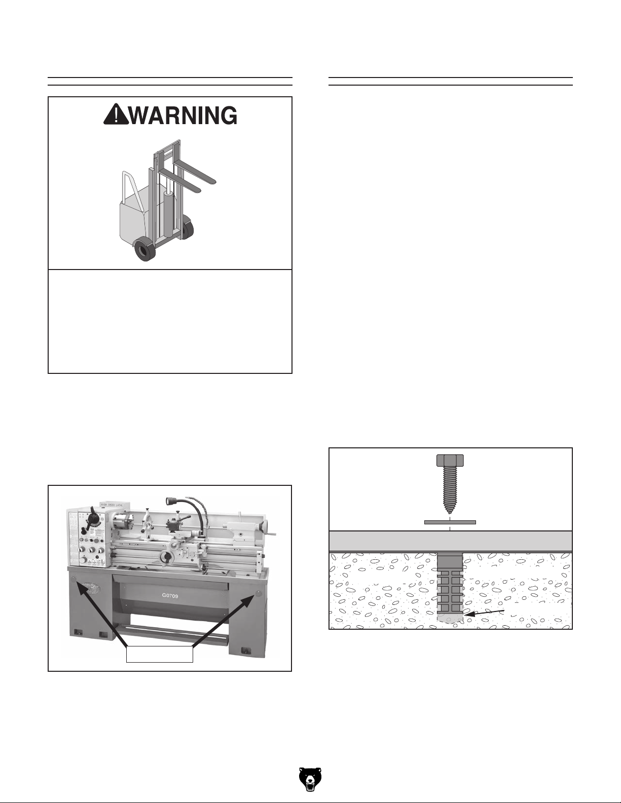
Anchoring to Floor
Anchoring to Concrete Floors
This lathe has a hole built into each end of the
stand (see Figure 8) that is designed to accept
a sturdy 1" diameter lifting bar. Each bar must
extend far enough from the stand so that chains
or lifting straps can be looped or connected to all
four corners and the lathe can be lifted.
Lifting Holes
Figure 8. Lifting holes.
Lag Screw
Flat Washer
Machine Base
Concrete
Figure 9. Popular method for anchoring
machinery to a concrete floor.
Lag Shield Anchor
Drilled Hole
Model G0709 (Mfg. Since 5/11)
-17-
Page 20
Leveling
For accurate turning results and to prevent
warping the cast iron bed and ways, the
lathe bedways MUST be leveled from sideto-side and from front-to-back on both ends.
Re-check the bedways 24 hours after
installation, two weeks after that, and then
annually to make sure they remain level.
Leveling machinery helps precision components,
such as bedways, remain straight and flat during
the lifespan of the machine. Components on a
machine that is not level may slowly twist due to
the dynamic loads placed on the machine during
operation.
For best results, use a precision level that is at
least 12" long and sensitive enough to show a
distinct movement when a 0.003" shim (approximately the thickness of one sheet of standard
newspaper) is placed under one end of the level.
Lubricating Lathe
It is critical that there is oil in the headstock,
quick change gearbox, and the apron gearbox
before proceeding with the test run. Refer to the
Lubrication instructions on Page 56 for more
details on which type and how much oil to use in
each gearbox.
GEARBOXES MUST
BE FILLED WITH OIL!
NO OIL SHIPPED WITH
MACHINE!
Refer to the Lubrication
Section in this Manual
for Recommended
Oil Type.
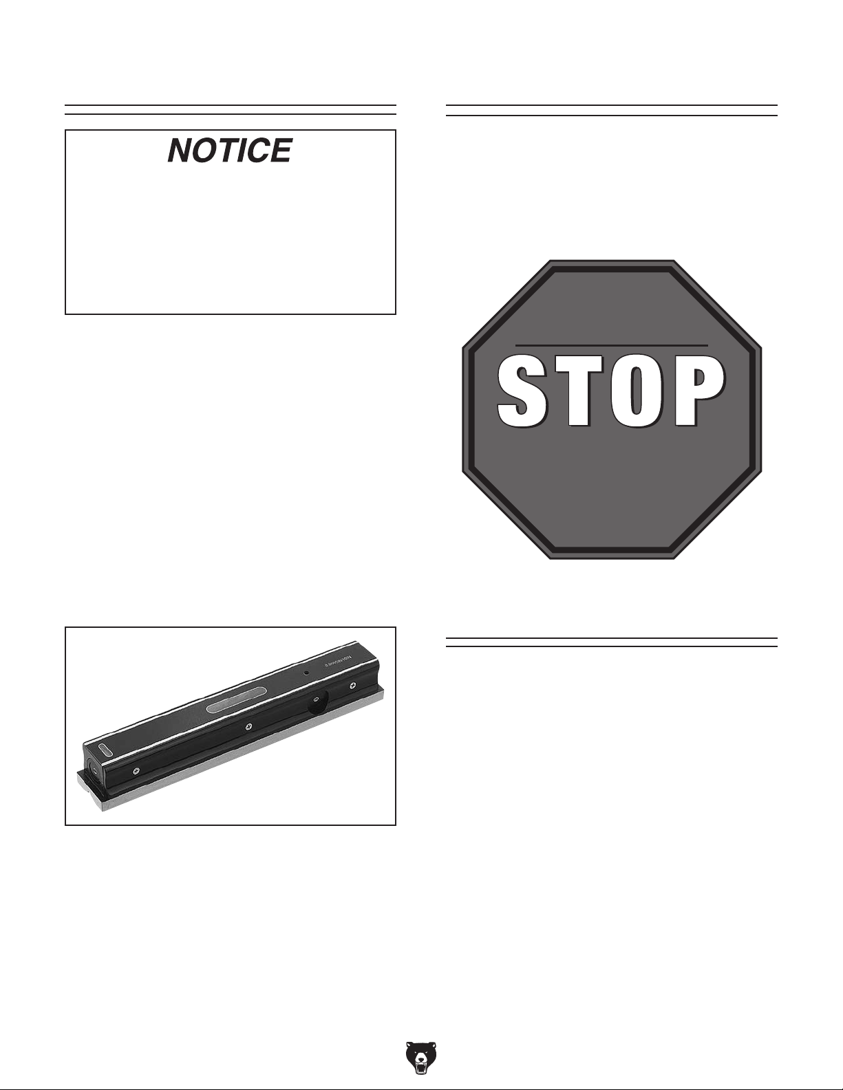
See the figure below for an example of a high
precision level.
Figure 10. Model H2683 precision level.
Adding Cutting Fluid
For detailed instructions on where the cutting
fluid tank is located and how to add fluid, refer to
Cutting fluid System on Page 58.
-18-
Model G0709 (Mfg. Since 5/11)
Page 21

Power Connection
Electrocution or fire
may occur if machine
is ungrounded, incorrectly connected to
power, or connected to
an undersized circuit.
Use an electrician or
qualified personnel to
ensure a safe power
connection.
Once all preparation steps previously described
in this manual have been completed, the machine
can be connected to the power source. In order to
be connected to the power source, a circuit must
be installed/prepared that meets the requirements
of the lathe, and a power connection method must
be established for that circuit.
Using an incorrectly sized cord causes machine
electrical components and the cord to become
very hot, which can lead to component failure or
result in fire. For best results, use the shortest
length of cord possible, and never use a smaller
cord gauge than the specified minimum.
Test Run
Once assembly is complete, test run the machine
to make sure it runs properly and is ready for regular operation. The test run consists of verifying
the following: 1) The motor powers up and runs
correctly and 2) the stop button safety feature
works correctly.
If, during the test run, you cannot easily locate
the source of an unusual noise or vibration, stop
using the machine immediately, then review
Troubleshooting on Page 59.
If you cannot find a remedy, contact our Tech
Support at (570) 546-9663 for assistance.
To begin the test run:
1. Make sure you understand the safety instruc-
tions at the beginning of the manual and that
all previous setup sections have been completed.
2. Make sure the lathe is lubricated and the
oil levels are at the full mark. Refer to
Maintenance on Page 53 for details.
3. Make sure the chuck is correctly secured to
the spindle. Refer to Chuck and Faceplate
Mounting on Page for detailed installation
instructions.
Model G0709 (Mfg. Since 5/11)
4. Make sure all tools and objects used during
setup are cleared away from the machine.
-19 -
Page 22
NOTICE
NEVER shift lathe gears when lathe is
operating, and make sure both the halfnut lever and the feed selection lever are
disengaged before you start the lathe!
Otherwise the carriage may feed into
the chuck or tailstock and cause severe
damage.
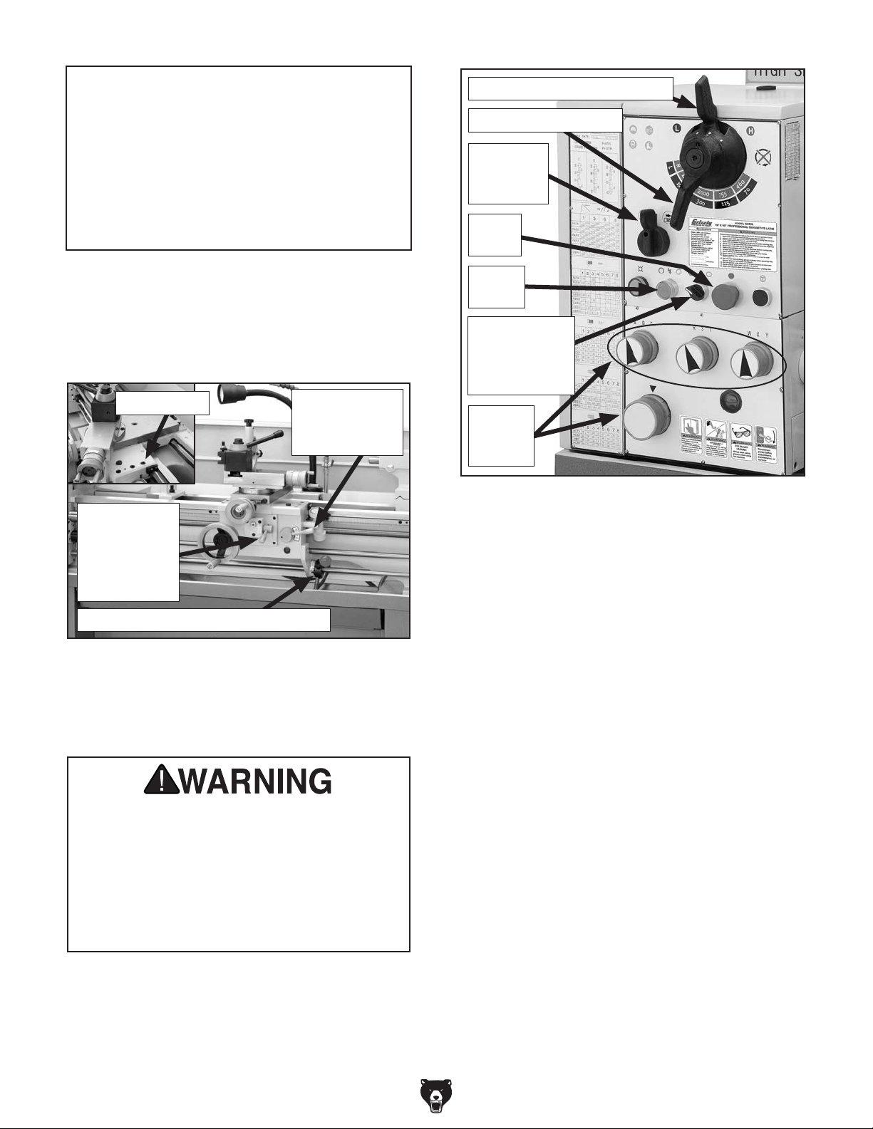
Spindle Speed Range Lever
Spindle Speed Lever
Feed
Direction
Lever
Stop
Button
5. Disengage the half-nut lever and the feed
selection lever (see Figure 11), and make
sure the saddle lock is loosened to allow the
lead screw or feed rod to move the apron if
required.
Saddle Lock
Feed
Selection
Lever is
Horizontal
(Disengaged)
Spindle ON/OFF Lever is Centered
Figure 11. Apron controls.
6. Make sure the cutting fluid pump switch is
OFF, point the cutting fluid nozzle into the
lathe chip pan.
Before starting the lathe, make sure you
have performed any preceding assembly
and adjustment instructions, and you have
read through the rest of the manual and
are familiar with the various functions and
safety features on this machine. Failure to
follow this warning could result in serious
personal injury or even death!
7. Rotate the stop button (Figure 12) clockwise
until it pops out.
8. Move the feed direction lever (see Figure 12)
to the disengaged middle position.
Half-Nut Lever
is Pulled Up
(Disengaged)
Power
Button
Cutting Fluid
ON/OFF
Switch
Feed
Speed
Dials
Figure 12. Headstock controls.
9. Move the spindle speed range lever to the "L"
position and move the spindle speed lever to
the "70" position.
Note: As long as the feed direction lever
shown in Figure 12 is disengaged, no torque
will be transmitted to the quick change gearbox or any other gear-driven component.
As a result, the feed speed dials shown in
Figure 12 can be left engaged or disengaged
for the test run.
10. Push the power button (see Figure 12), then
move the spindle ON/OFF lever (see Figure
11) downward to start the lathe. The spindle
will rotate at 70 RPM.
—If the top of the chuck is rotating toward
you, the lathe motor is rotating in the correct direction. Continue to the next Step.
—If the top of the chuck is rotating away from
you, reverse the motor rotation. Refer to
the Motor Wiring diagram on Page
and follow the NOTICE on that page.
—When operating correctly, the machine
runs smoothly with little or no vibration or
rubbing noises.
78,
-20-
Model G0709 (Mfg. Since 5/11)
Page 23

— Investigate and correct strange or unusual
noises or vibrations before operating the
machine further. Always disconnect the
machine from power when investigating
or correcting potential problems. If the
problem is not readily apparent, refer to
Troubleshooting on Page 59.
11. Move the spindle ON/OFF lever up to the
center position, and press the stop button.
12. WITHOUT resetting the stop button, move
the spindle ON/OFF lever down. The machine
should not start.
—If the machine does not start, the stop
button safety feature is working correctly.
Continue to the next Step.
—If the machine starts (with the stop button
pushed in), immediately disconnect power
to the machine. The stop button safety
feature is not working correctly. This safety
feature must work properly before proceeding with regular operations. Call Tech
Support for help.
13. Rotate the stop button clockwise until it pops
out.
14. Make sure the lamp works.
15. Make sure that the cutting fluid nozzle is
pointing toward the chip pan, then turn the
cutting fluid pump switch ON, and open the
nozzle valve. After verifying that cutting fluid
flows from the nozzle, turn the cutting fluid
switch OFF.16. Start the spindle, then step
on the brake pedal. The power to the motor
should be cut and the spindle should come to
an immediate stop.
Model G0709 (Mfg. Since 5/11)
-21-
Page 24

Spindle Break-In
Before subjecting the spindle to operational loads,
it is essential to complete the break-in process.
This helps ensure maximum life of spindle bearings and other precision components by thoroughly lubricating them before placing them under
load.
After spindle break-in is complete, we recommend
changing headstock and gearbox oil to remove
any metal particles or debris that are present from
the assembly and break-in process.
The break-in must be performed in succession
with the
manual, as the steps in that procedure prepare
the lathe controls for the break-in process.
Test Run procedure described in this
DO NOT perform this procedure independently of the Test Run section. The lathe
could be seriously damaged if the controls
are set differently than instructed in that
section.
Recommended
Adjustments
For your convenience, the adjustments listed
below have been performed at the factory.
However, because of the many variables involved
with shipping, we recommend that you at least
verify the following adjustments to ensure the best
possible results from your new machine.
Step-by-step instructions for these adjustments
can be found in the SERVICE section starting on
Page 59.
Factory adjustments that should be verified:
• Verify Three-Jaw Chuck Registration in
Chuck and Faceplate Removal/Installation
(Page 27)
• Camlock Stud Installation (Page 29)
• Gib Adjustments (Page 61)
• Tailstock Alignment (Page 36)
To perform the spindle break-in:
1. Successfully complete the Test Run proce-
dure beginning on Page 19.
2. Disengage the half-nut lever and the feed
selection lever.
3. Run the spindle at 70 RPM for 10 minutes
each in direction (first forward and then
reverse).
4. Repeat running the lathe in this manner
through the rest of the spindle speeds, progressively increasing in RPM.
5. Press the stop button and DISCONNECT
THE LATHE FROM POWER! The lathe is
broken in.
Congratulations! Spindle break-in is complete. We
recommend changing the headstock and gearbox
oil before operating the machine further (refer to
Lubrication on Page 56).
• Backlash Adjustment (Page 63)
-22-
Model G0709 (Mfg. Since 5/11)
Page 25

SECTION 4: OPERATION
The purpose of this overview is to provide the novice machine operator with a basic understanding
of how the machine is used during operation, so
the
discussed later
in this manual
Due to the generic nature of this overview, it is
not
more about specific operations,
manual and
rienced
research outside of this manual by reading "howto" books, trade magazines, or websites.
To reduce your risk of
serious injury, read this
entire manual BEFORE
Operation Overview
machine controls/components
are easier to understand.
intended to be an instructional guide. To learn
read this entire
seek additional training from expe
machine operators, and do additional
To complete a typical operation, the operator
does the following:
1. Puts on safety glasses, rolls up sleeves,
removes jewelry, and secures any clothing,
jewelry, or hair that could get entangled in
moving parts.
2. Examines the workpiece to make sure it
is suitable for turning, then mounts the
workpiece required for the operation.
3. Mounts the tooling, aligns it with the workpiece,
then adjusts it for a safe startup clearance.
4. Clears all tools from the lathe.
5. Sets the correct spindle speed for the opera-
tion.
using machine.
To reduce the risk of
eye injury from flying
chips always wear safety
glasses.
If you are not experienced with this type
of machine, WE STRONGLY RECOMMEND
that you seek additional training outside of
this manual. Read books/magazines or get
formal training before beginning any projects. Regardless of the content in this section, Grizzly Industrial will not be held liable
for accidents caused by lack of training.
6. Checks for safe clearances by rotating the
workpiece by hand one full revolution.
7. Moves slides to where they will be used during operation. If using power feed, selects the
proper feed rate for the operation.
8. Turns the main power switch ON, resets the
stop button so it pops out, then moves the
spindle ON/OFF lever down to start spindle
rotation. The spindle will rotate forward (the
top of the chuck rotates toward the operator).
9. Uses the carriage handwheels or power feed
options to move the tooling into the workpiece
for operations.
10. When finished cutting, moves the ON/OFF
lever to the center position to turn the lathe
OFF, then removes the workpiece.
Model G0709 (Mfg. Since 5/11)
-23-
Page 26
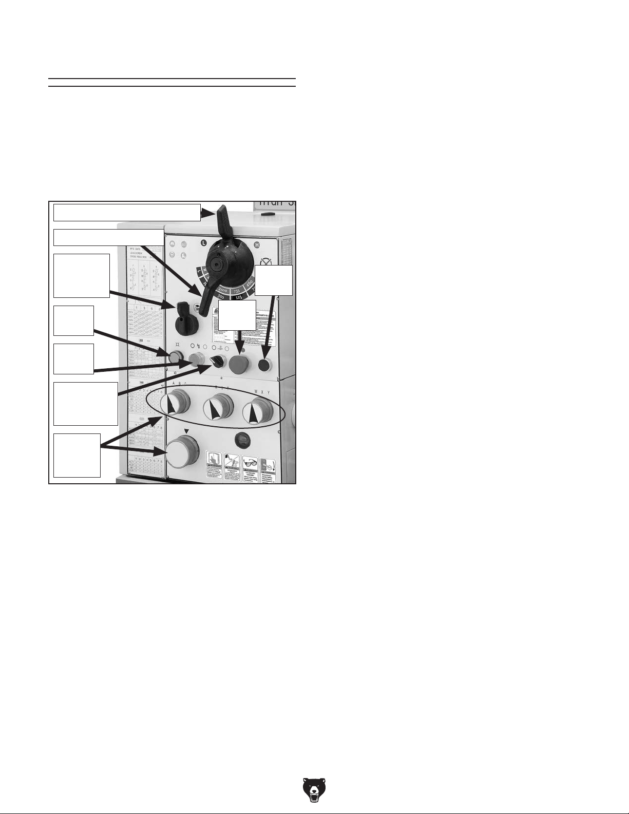
Controls
Headstock Controls
Use the descriptions in this section and the controls shown in Figure 13 to quickly understand
the functions of the headstock and quick change
gearbox controls, and to find their locations on the
lathe.
Spindle Speed Range Lever
Spindle Speed Lever
Feed
Direction
Lever
Power
Light
Power
Button
Cutting
Fluid ON/
OFF Switch
Stop
Button
Jog
Button
Power Light
When the lathe is connected to power, it is not
necessarily ready for use. Only when the stop button is twisted clockwise and popped-out, and the
ON button has been pushed will the power light
illuminate and indicate that all electrical controls
are "LIVE" and ready for use. Just because the
power light is OFF, do not assume that the lathe
is safe for electrical work, general adjustments,
or workpiece changes. You must always disconnect the lathe from power before attempting any
of these tasks.
Power Button
Prevents accidental start up. Every time the stop
button is pressed in and then reset, the power button must be pressed. If there has been a power
outage while the lathe was operating, when power
is resumed, the power button must be pressed to
reactivate the power to the control panel. If the
foot brake is pressed, a limit switch will cut power
to the motor immediately.
Cutting fluid ON/OFF Switch
Toggles the cutting fluid pump ON or OFF. Never
turn the cutting fluid pump on and let it run while
the reservoir is empty, or pump damage may
occur.
Feed
Speed
Dials
Figure 13. Headstock controls.
Spindle Speed Range Lever
Alternately engages drive gears to produce high
or low range operation in the headstock.
Spindle Speed Lever
Controls the spindle speed only and has no effect
on the gearbox speed or the apron feeds.
Feed Direction Lever
Controls the forward and reverse direction of the
carriage and cross feed. When this lever moved
left or right, the direction of the quick change
gearbox, feed rod, and lead screw reverse direction, but spindle direction is unaffected.
Feed Speed Dials
Engage either the feed rod or leadscrew, and set
the apron speed for threading, turning, or facing
operations.
Stop Button
Cuts power to the spindle motor and the control
panel. No braking occurs and the spindle, chuck,
and workpiece wind-down naturally. After being
pressed, the stop button stays pushed in until it is
reset by twisting the knob clockwise until it pops
back out.
Jog Button
Bumps the motor ON and OFF so partial spindle
rotation occurs in reverse. Useful when the lathe
is stopped in low range and the lathe gear reduction makes it difficult for the machinist to rotate
the chuck by hand in order to reposition a chuck
or workpiece.
Note: In order to use the jog button, the Spindle
ON/OFF lever must be in the central or OFF position.
-24-
Model G0709 (Mfg. Since 5/11)
Page 27
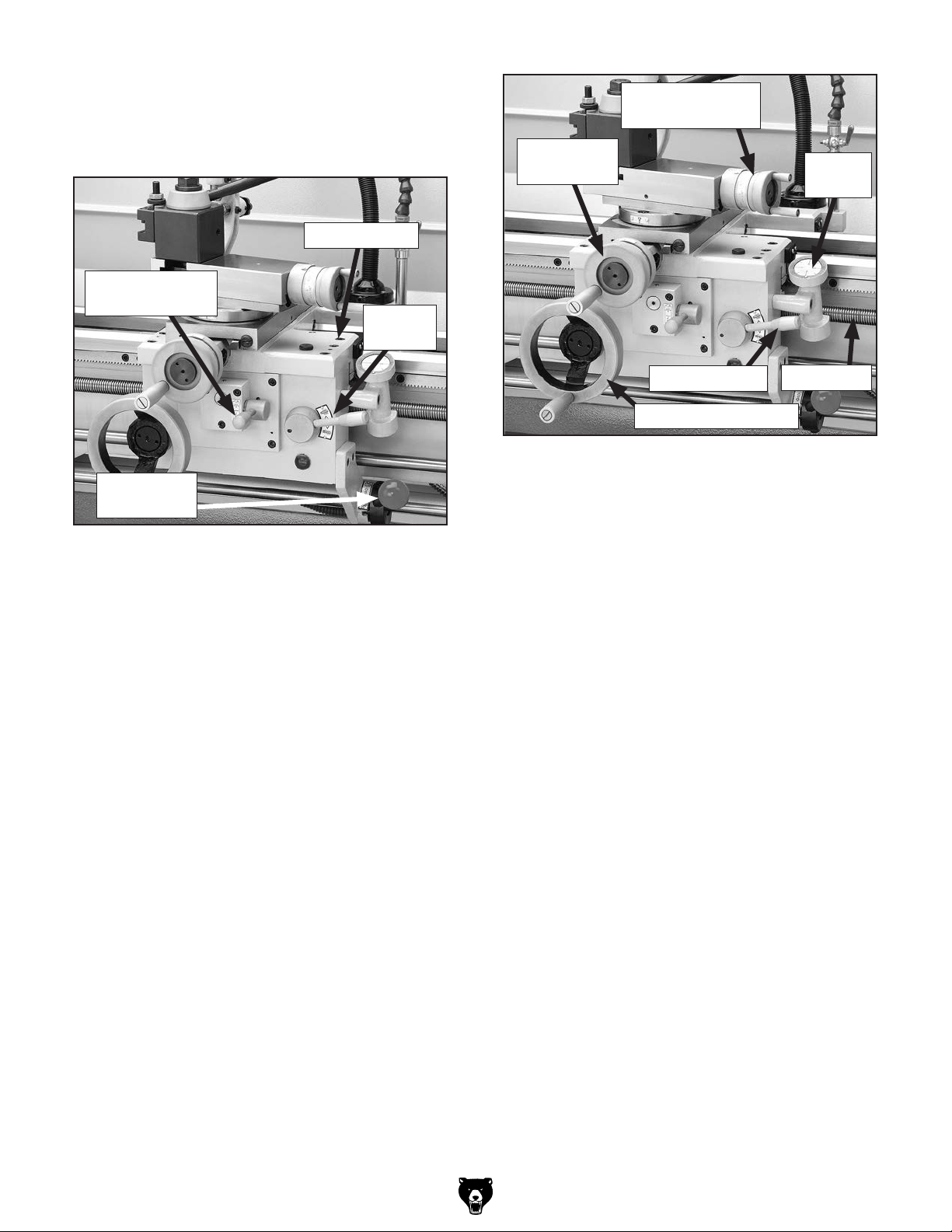
Apron Controls
Use the descriptions in this section and the controls shown in Figure 14 to quickly understand
the functions of the apron and its related controls.
Carriage Lock
Feed Selection
Lever
Half nut
Lever
Cross Feed
Handwheel
Compound Slide
Handwheel
Thread
Dial
Spindle ON/
OFF Lever
Figure 14. Carriage lever controls.
Spindle ON/OFF Lever
Starts and stops the spindle in forward and
reverse.
• Moving the lever downward from the central
OFF position spins the chuck forward (the top
of the chuck moves toward the machinist).
• Moving the lever upward from the central OFF
position spins the chuck in reverse (the top of
the chuck moves away from the machinist).
Feed Selection Lever
Allows the machinist to engage or disengage the
apron for longitudinal or cross feeding tasks.
Half nut Lever
Carriage Handwheel
Figure 15. Apron controls.
Carriage Handwheel
For moves the carriage longitudinally left or right
along the ways.
Cross Slide Handwheel
Moves the cross slide in or out perpendicular to
carriage travel and is equipped with a "Standard
Dial" that has a ratio of 1:2.
Compound Slide Handwheel
Moves the compound and cutting tool relative to
the workpiece at various angles with fine-depth
control.
Compound Slide Scale
The 110° rosette on the top of the compound indicates compound angles. Zero splits the scale into
two ranges, 55° to the right and 55° to the left in
1° degree increments.
Leadscrew
Carriage Lock
Clamps the right front of the saddle to the lathe way
for increased rigidity when facing a workpiece.
Half-Nut Lever
Clamps the halfnut to the leadscrew for inchthreading operations.
Thread Dial
Avoids cross-cutting inch threads by indicating to
the machinist where to re-clamp the half nut in
order to resume threading after a carriage return.
Model G0709 (Mfg. Since 5/11)
-25-
Page 28
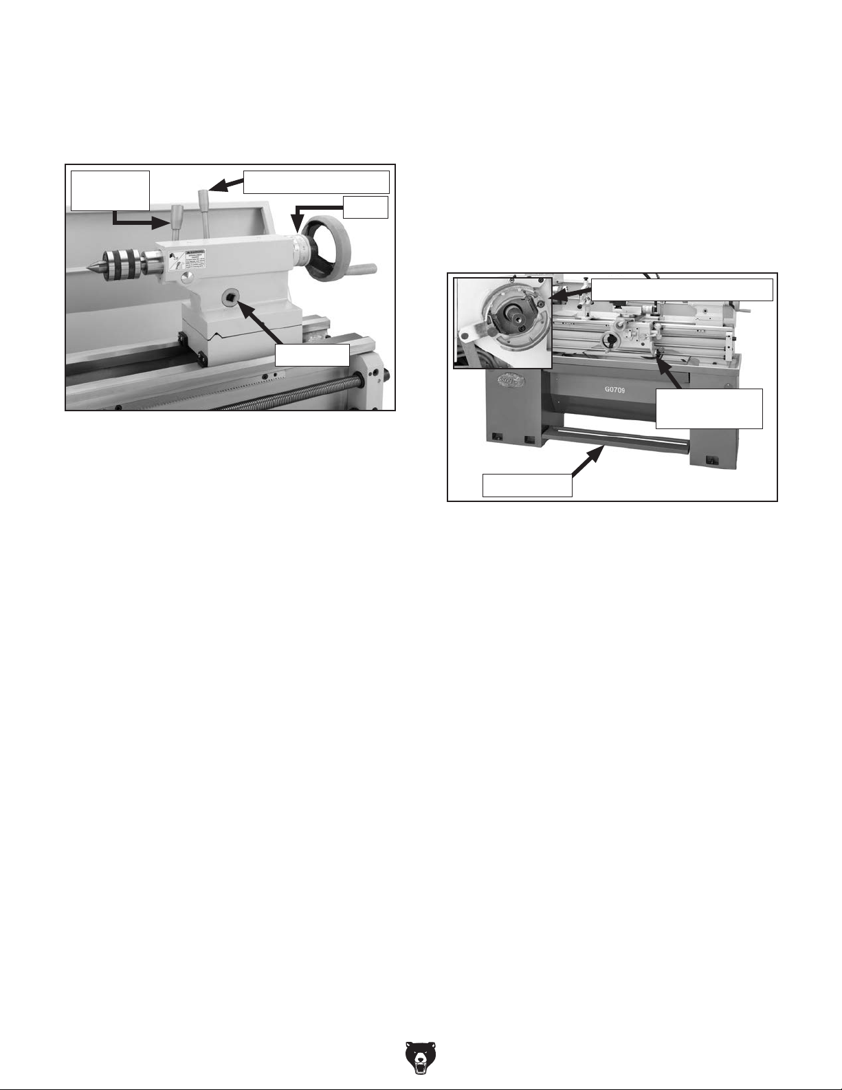
Tailstock
Brake
Use the descriptions in this section and the controls shown in Figure 16 to quickly understand the
functions of the tailstock controls.
Quill Lock
Lever
Tailstock Lock Lever
Scale
Drive Hub
Figure 16. Tailstock controls.
Quill Lock Lever
Secures the quill in a locked or pre-loaded position.
Tailstock Lock Lever
Clamps the tailstock in place for general position
locking along the lathe bed.
When pressed, the brake pedal (see Figure 17)
actuates mechanical linkage that expands brake
shoes within the spindle drive pulley and stops
the lathe spindle. At the same time the motor
power supply circuit is cut by a linkage-controlled
limit switch. To resume lathe operations after the
brake has been used, return the spindle ON/OFF
lever to the central position, and all lathe controls
become "LIVE" again.
Brake Shoes and Linkage
Spindle
ON/OFF Lever
Brake Pedal
Figure 17. Spindle brake system.
Drive Hub
Allows the tailstock to be locked in place using a
1
⁄2" drive torque wrench to control amount of draw-
down alignment with the spindle centerline.
Tailstock Handwheel
Advances or retracts the quill in the tailstock
at a 1:1 ratio with the micrometer scale on the
handwheel hub.
Micrometer Scale
Displays quill travel in increments of 0.001" with
a total rotation value of 0.100", (for every full rota-
1
tion of the handwheel, the quill moves
⁄10"). The
tailstock quill is broken down with an inch scale up
to 4" and a metric scale up to 100mm.
-26-
Model G0709 (Mfg. Since 5/11)
Page 29
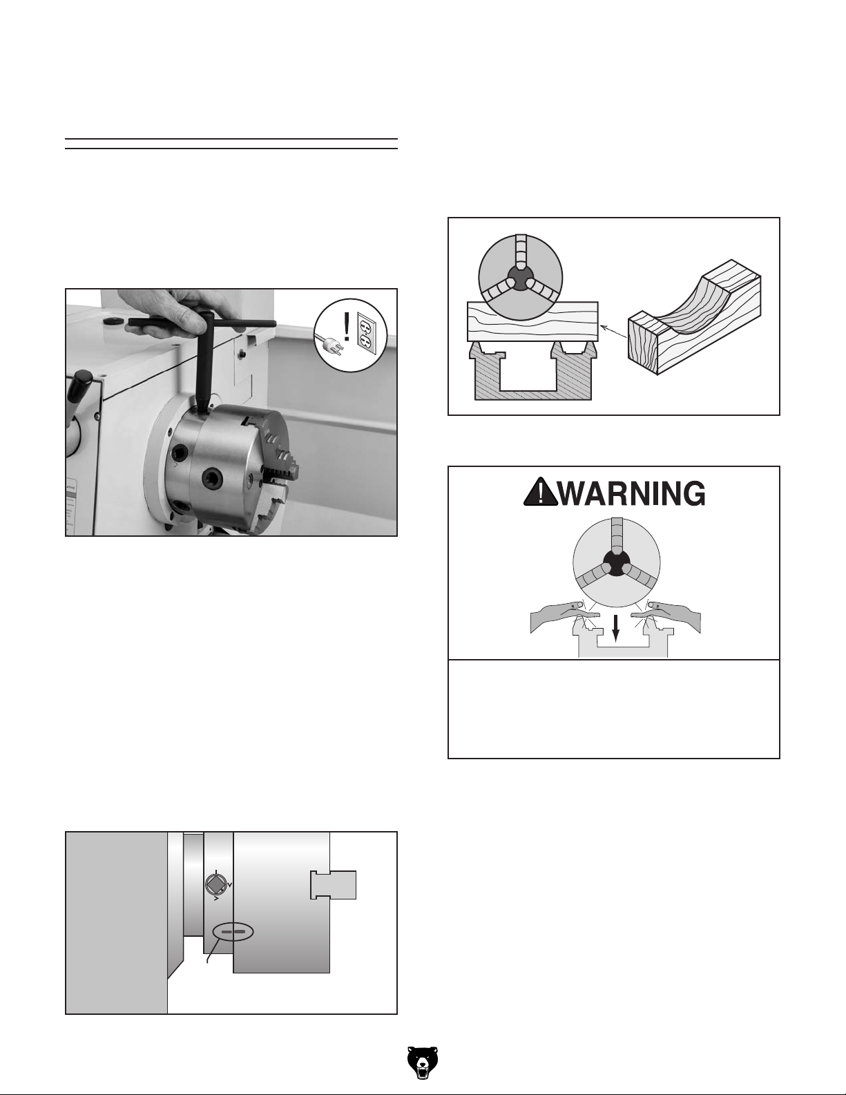
Chuck & Faceplate
Removal/Installation
This lathe is shipped with a 3-jaw chuck installed,
but also includes a 4-jaw chuck and 12" faceplate.
The chucks and faceplate mount to the spindle
with a D1-5 camlock system, which uses a key to
loosen and tighten camlocks for removal or installation (see Figure 18).
Chuck & Faceplate Removal
1. DISCONNECT LATHE FROM POWER!
2. Lay a chuck cradle (see Figure 20) or a layer
of plywood over the bedways to protect the
precision ground surfaces from damage and
to prevent fingers from being pinched.
Figure 20. Simple chuck cradle made of scrap
lumber.
Figure 18. Chuck key positioned to remove a
typical camlock mounted chuck.
Before the 4-jaw chuck and faceplate can be
installed on the spindle, their respective cam
studs must be installed and adjusted.
To maintain consistent removal and installation
of the chucks and faceplate, each should have a
timing mark that can be lined up with a matching
one on the spindle, so it will be installed in the
same position every time (see Figure 19). Before
removing the 3-jaw chuck, verify that a timing
mark exists. If a mark cannot be found, stamp
your own on both the chuck and spindle.
Timing
Marks
PINCH HAZARD! Protect your hands and
the precision ground bedways with plywood
or a chuck cradle when removing the lathe
chuck! The heavy weight of a falling chuck
can cause serious injury.
3. Loosen the cam-locks by turning the key
counterclockwise approximately one-third of
a turn until the mark on the cam-lock aligns
with the single mark on the spindle nose in
Figure 21. If the cam-lock stud does not
freely release from the cam-lock, wiggle the
cam-lock until the cam-lock stud releases.
Note: These cam-locks may be very tight. A
breaker bar may be used to add leverage.
Figure 19. Chuck/spindle timing marks.
Model G0709 (Mfg. Since 5/11)
-27-
Page 30
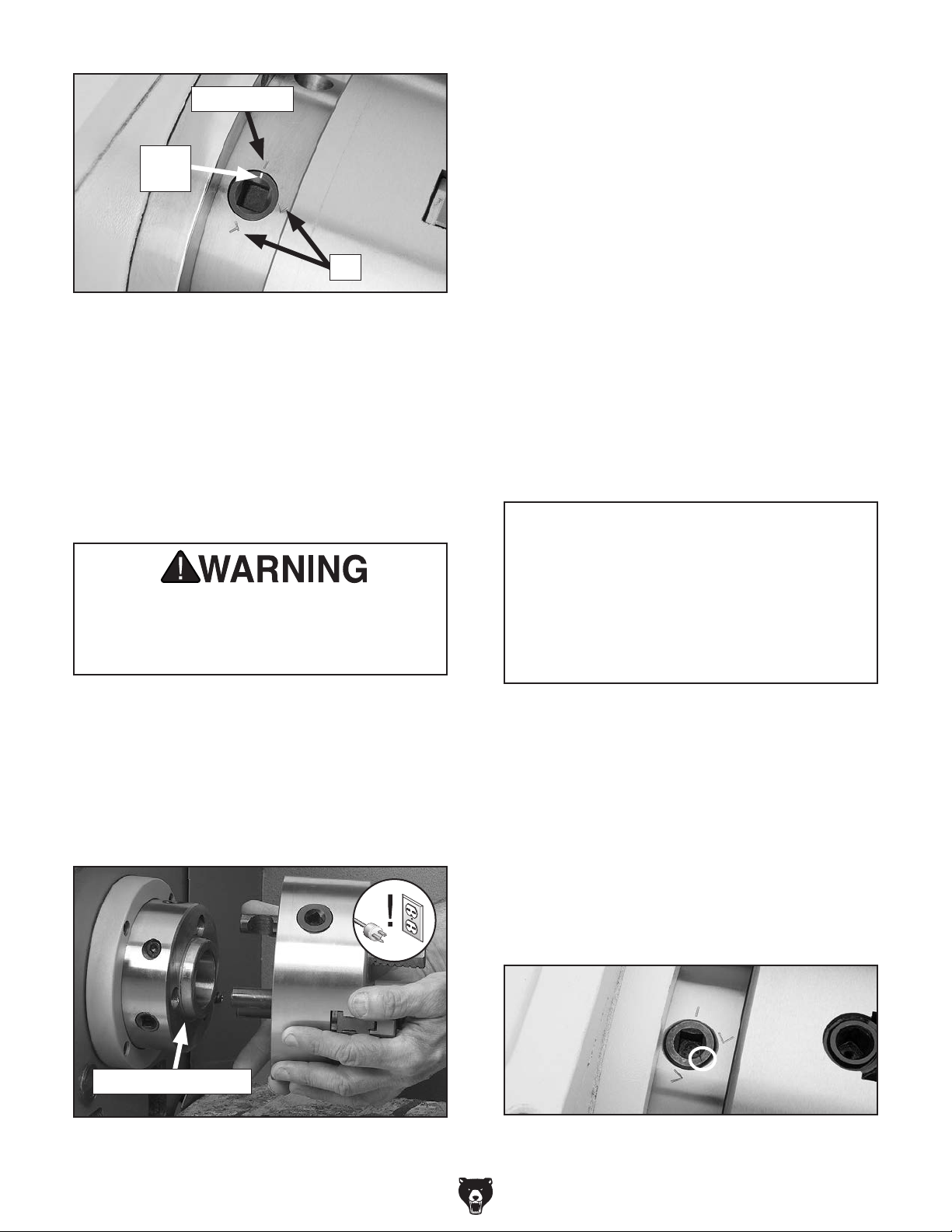
Spindle Line
To install the chuck or face plate:
Chuck & Faceplate Installation
1. DISCONNECT LATHE FROM POWER!
Cam
Line
V's
Figure 21. Indicator arrows.
4. Using a dead blow hammer or other soft mal-
let, lightly tap around the outer circumference
of the chuck body to break the chuck free
from the cam-locks and from the spindle nose
taper.
CAUTION: The chuck may come off at this
point, so it is important you are ready to
support its weight.
Large chucks are very heavy. Always get
assistance when removing or installing
large chucks to prevent personal injury or
damage to the chuck or lathe.
2. Place a piece of plywood across the lathe
ways just under the chuck, and use a chuck
cradle if desired.
3. Make sure the chuck taper and spindle taper
mating surfaces are perfectly clean.
4. Inspect and make sure that all camlock studs
are undamaged, are clean and lightly oiled,
and that the camlock stud cap screws are in
place and snug.
—If the camlock studs have not yet been
installed in the chuck or faceplate, complete the Camlock Stud Installation on
the next page.
NOTICE
Never install a chuck or faceplate without
having the camlock cap screws in place
or fully tightened. If you ignore this notice,
once installed the chuck may never be able
to be removed since the camlock studs will
turn with the camlocks and never release.
5. Use a rocking motion to carefully remove the
chuck from the spindle (see Figure 22).
—If the chuck does not immediately come off,
rotate the spindle approximately 60˚ and
tap again. Make sure all the marks on the
cams and spindle are in proper alignment.
Spindle Nose Taper
Figure 22. Installing and removing a typical
camlock style chuck.
5. Align the chuck-to-spindle timing marks (see
Figure 24), and slide the chuck onto the
spindle.
6. Turn a camlock with the chuck wrench until
the cam mark falls between the "V" marks as
shown in Figure 23.
— If the cam lock mark stops outside of the
“V” marks, remove the chuck and adjust
the cam stud height of the offending studs
one full turn up or down (see Figure 23).
Figure 23. Cam-lock in the locked position.
-28-
Model G0709 (Mfg. Since 5/11)
Page 31

7. Lock the other cams in a star pattern so the
chuck is drawn up evenly on all sides without
any chance of misalignment.
Note: If any of the cam lock marks (see
Figure 24) do not fall between the "V" marks
when the cam lock is tight, you must adjust
the offending camlock stud as discussed in
Camlock Stud Installation.
Camlock Stud Installation
1. Oil and thread each cam stud into the chuck
until the alignment groove is flush with the
chuck surface as shown in Figure 24.
2. Install and tighten the locking cap screw for
each stud, making sure that the camlock
studs can slightly rotate back and forth.
8. Remove the chuck wrench.
When using this lathe,
securely clamp your
workpiece and remove the
chuck wrench! Thrown
objects from a lathe can
cause serious injury or
death to the operator and
to bystanders.
Cap Screw
Installed & Tight
3. Place the chuck onto the spindle and tighten
the cam locks in an alternating manner to
avoid cocking the chuck on the spindle.
When tightened:
— If the cam lock mark stops outside of the
"V" marks, remove the chuck and adjust
the cam stud height of the offending studs
one full turn (see Figure 24).
— If the final position of each cam mark is
between the two "V" marks as shown in
Figure 24, no stud adjustment is required.
Camlock Stud
Must Slightly
Rotate Back/Forth
Initial Adjustment:
Camlock Stud Alignment
Groove is Flush with Chuck
Surface
Cam Lock Positioning:
To Correct :
Turn Stud One Turn In
To Correct:
Turn Stud One Turn Out
Cam Release
Datum
Timing
Marks
CORRECT
The Camlock Mark
Stops Between the
“V” Marks.
Model G0709 (Mfg. Since 5/11)
INCORRECT
The Camlock Mark
Stops After the
“V” Marks.
Figure 24. Camlock stud alignment.
INCORRECT
The Camlock Mark
Stops Before the
“V” Marks.
-29-
Page 32

Three-Jaw Chuck
To use the 3-jaw chuck:
1. DISCONNECT LATHE FROM POWER!
This section outlines basic operation safety related
to using the 3-jaw chuck included with your lathe.
Use knowledge of safety and common sense
when applying the steps on how to use this chuck.
If you have any questions, feel free to contact our
Technical Support Department.
The 3-jaw chuck shipped with this late has a twopiece reversible jaw design. An internal scrollgear, moves all jaws in unison when adjusted. This
chuck will hold cylindrical parts on-center with the
axis of spindle rotation, and can be spun at high
speeds if the workpiece is properly clamped and
is balanced. If a workpiece must be held from the
inside, rotate all three of the two-piece jaws 180°
so the orientation of all jaws match. Otherwise
the chuck will spin out of balance an create an
extreme thrown workpiece hazard!
Reversing Jaw Positions & Clamping
a Workpiece
Figure 25 shows a typical example of clamping
options available with a 3-jaw chuck. The chuck
included with this lathe has reversible jaws, which
means the lower jaw or master jaw do not need to
be removed to reverse the jaw position. Instead,
the top jaw is fastened to the master jaw with
cap screws that when removed allow for top jaw
reversal. It is a good practice to keep the top jaws
matched with their original master jaw, to ensure
maximum quality of alignment and exact fit.
2. Remove the cap screws that retain the top
portion of one of the jaws (see Figure 26),
and remove the jaw.
Figure 26. Reversing the chuck jaws.
Clamping on an Outside Diameter
Clamping in an Inside Diameter
Figure 25. Three-jaw chuck OD & ID clamping.
-30-
3. Making sure the longer cap screw remains in
the thicker part of the jaw, rotate the jaw 180˚
and re-install it to the lower jaw (see Figure
26).
4. Repeat Steps 2–3 on the remaining jaws
Always securely tighten
jaws and remove all tools
from the lathe before starting spindle! Thrown objects
from a lathe can cause serious injury or death to the
operator and to bystanders.
Model G0709 (Mfg. Since 5/11)
Page 33

Four-Jaw Chuck
To use the 4-jaw chuck:
1. DISCONNECT LATHE FROM POWER!
This section outlines basic operation safety related
to using the 4-jaw chuck included with your lathe.
Use knowledge of safety and common sense
when applying the steps on how to use this chuck.
If you have any questions, feel free to contact our
Technical Support Department.
Select this chuck for low-speed lathe operations
only. The 4-Jaw chuck uses independently adjustable jaws, meaning each is adjusted by an individual worm gear. Non-cylindrical parts can be held
and brought into the spindle centerline for facing
or boring. The other benefit is that the majority of
a workpieces can be positioned out of the spindle
rotation axis if a bore or step needs to be cut into
a workpiece on an outlying edge.
For the best grip possible on odd-shaped
workpieces, one or more jaws can also be rotated
180° to grab more surface area for clamping.
If all four jaws cannot be used to hold the workpiece,
you must use the faceplate for improved clamping
options. Otherwise, a severe out-of-balance condition will be created. If spun even at an average
speed, this chuck will almost always be out of balance, and the machinist and bystanders will be at
risk of being hit with a thrown workpiece. Being hit
by an ejected workpiece can be fatal.
2. Install a center in the tailstock.
3. Open each jaw with the chuck wrench and
place the workpiece flat against the chuck
face.
4. Support the workpiece and slide the tailstock
forward so the tip of the dead center presses
against the workpiece. Next, lock the tailstock
in position. For more information, refer to the
tailstock controls on Page 67 and Centers on
Page 33.
5. Turn the tailstock quill so the dead center
applies enough pressure to the center point
of your workpiece to hold it in place (see
Figure 28), then lock the tailstock quill.
First
Fourth
Third
Second
Reversing Jaw Positions & Clamping
a Workpiece
Shown in Figure 27 is an example of the independent jaws holding a non-cylindrical workpiece
for off-center boring. One or more jaws can be
reversed in any combination to get the best grip
on the workpiece.
Figure 27. Four-jaw chuck independent
jaw-clamping with two jaws reversed.
Model G0709 (Mfg. Since 5/11)
Figure 28. Centering workpiece (tool post
removed for clarity).
6. Turn each jaw until it just makes contact with
the workpiece.
7. Tighten each jaw in small increments. After
adjusting the first jaw, continue tightening in
opposing sequence (see Figure 28). Check
frequently to make sure the required point on
the workpiece has not wandered away from
the spindle centerline due to applying too
much pressure to a single jaw.
-31-
Page 34

8. After the workpiece is held in place, back the
tailstock away and rotate the chuck by hand.
The center point will move if the workpiece is
out of center (see Figure 29).
Figure 29. Properly held workpiece for low
speed offset boring or machining.
9. Make fine adjustments by slightly loosening
one jaw and tightening the opposing jaw until
the workpiece is held securely and precisely
aligned with the spindle centerline.
Faceplate
This section outlines basic operation safety related to using the faceplate included with your lathe.
Use knowledge of safety and common sense
when applying the steps on how to use this faceplate. If you have any questions, feel free to contact our Technical Support Department.
The faceplate is cast-iron and has multiple slots
for T-bolts that hold clamping hardware. If you
suspect that any of the chuck or jaw combinations may not hold a workpiece safely, remove
the chuck and install the faceplate as outlined for
special clamping options.
However, just as with the 4-Jaw chuck, not
all workpieces can be safely held. Holding a
workpiece off center or holding an irregular-
shaped workpiece will cause the entire assembly
to rotate out of balance. If spun at any speed
higher than low, the workpiece can eject hitting
the lathe operator or bystanders causing a severe
or fatal injury.
Figure 30 shows an example of a workpiece being
improperly held with the 4-jaw chuck. One jaw of
the chuck interfered with the workpiece edge, and
removing the jaw creates an extreme workpiece
ejection hazard. The workpiece holding solution
shown in Figure 30 is to use the faceplate with
a minimum of three clamps that are spaced as
equally apart as possible for full support.
Faceplate
4-Jaw Chuck
NOYES
Figure 30. Workpiece to faceplate clamping.
-32-
Model G0709 (Mfg. Since 5/11)
Page 35

To use the faceplate:
1. DISCONNECT LATHE FROM POWER!
Centers
2. Insert a dead center into the tailstock, slide
the tailstock up to the faceplate, and lock the
tailstock into position.
3. Place the workpiece against the faceplate
and turn the tailstock quill so the point of the
dead center touches and applies enough
pressure to hold the workpiece in place.
4. Lock the quill when sufficient pressure is
applied to hold the workpiece. Additional
support may be needed, depending on the
workpiece.
5. Clamp the workpiece at a minimum of three
locations that are as close to being evenly
spaced apart as possible as shown in Figure
31.
The Model G0709 lathe is supplied with two MT#3
dead centers, an MT#3 live center, and a MT#5–
MT#3 adapter sleeve (see Figure 32) to adapt the
centers into spindle bore. When installing centers
verify that all mating surfaces are clean and free
of nicks and burrs.
Tip: Hand-held tapered bore wipers make this
task very time efficient, and offer consistently
clean bores.
Live CenterCarbide-Tipped Dead Center
Solid Dead Center
Sleeve
Figure 32. Included centers and sleeve.
Figure 31. Workpiece properly clamped on the
faceplate in a minimum of three locations
(tailstock removed for clarity).
Use a minimum of three independent clamping devices when using faceplate. Failure
to provide adequate clamping may cause
workpiece to eject during operation.
6. Double check for safety and rotation clear-
ance.
7. Slide the tailstock away from the workpiece
and install the required tailstock tooling for
drilling or boring, or position the tool bit for
facing.
Model G0709 (Mfg. Since 5/11)
Solid Dead Center
Dead centers are typically used in low speed turning operations to increase rigidity for close tolerances. The solid dead center is installed at the
spindle end of the lathe because the workpiece,
center, and spindle all turn together by the use of
a lathe dog. One end of the lathe dog is clamped
to the workpiece, and the other end the tail, is
inserted into a faceplate slot shown in Figure 33).
Tip: If the tail is too large for a slot, install the
3-jaw chuck, open the jaws so the workpiece can
be supported by the center and the tail of the dog
can rest against a jaw.
Faceplate Slot
Solid Dead Center
Figure 33. Faceplate and dead center setup.
-33-
Page 36

Carbide-Tipped Dead Center
When the workpiece is supported at the tailstock
end of the lathe, the workpiece will spin on the tip
of the fixed center. To eliminate the tip of the center from wearing out at this point of contact, the
carbide-tipped center is used. Nevertheless, during turning operations this tip must still be lubricated vigilantly, or the workpiece will wear, resulting in increased end play and poor turning results.
Typically, when using centers, the tailstock quill
should be locked and protrude at least
more than 3".
1
⁄2 ", but not
Live Center
If the workpiece must be spun at higher speeds,
the live center is inserted into the tailstock (see
Figure 34). Unlike a dead center, the tip of the live
center is supported with precision bearings that
allow it to support and spin with the workpiece.
As a result, virtually no wear occurs, and the
workpiece can be turned with less concern about
developing end play from tip wear. However,
when using live centers, accuracy can suffer as
a result of having bearings support the end of the
workpiece.
Carbide-Tipped Solid Dead
Center
Figure 35. Inserting a carbide-tipped dead
center in the tailstock.
3. Position the tailstock so the center presses
against the workpiece, then lock the tailstock
in place.
4. Preload the quill into the workpiece. The
force against the workpiece will fully seat the
tapered center.
5. Lock the quill into place. However, keep in
mind that the quill may need to be adjusted during operation to remove any play
that develops between the center and the
workpiece.
To install a center into the tailstock:
Removing Center from Tailstock
To remove a center, hold the end of the center
with a rag to prevent it from falling, and reverse
the handwheel until the center is pressed free.
Figure 34. Live center installed in a tailstock.
Installing Center in Tailstock
1. Center drill the end of the workpiece to be
turned or threaded.
2. Feed the quill out about 1", wipe clean and
insert the center into the quill bore (see
Figure 35). To help prevent wear, place a
dab of grease on the point of the center.
To install a center into the tailstock:
-34-
Installing Center in Spindle
1. Install the dead center into the spindle
sleeve.
2. Install the sleeve into the spindle bore.
3. Determine whether to use the chuck or face-
plate, and install the required unit.
4. Clamp the required lathe dog onto the
workpiece and mount the workpiece between
the lathe centers.
Removing Center from Spindle
To remove a center and sleeve, hold the end of
the center with a rag to prevent it from falling,
insert a wooden rod into the outboard side of the
spindle, and tap the center and sleeve free.
Model G0709 (Mfg. Since 5/11)
Page 37

Tailstock
Offsetting Tailstock
Quill Lock Lever
The quill lock lever (see Figure 36) secures the
quill in its current position. When drilling, or when
tapping operations need to be done deep into a
part, the quill can also be stabilized by slightly
applying the lever to add drag and preload to the
quill.
Quill Lock
Lever
Figure 36. Tailstock controls.
Tailstock Lock Lever
Scale
1
⁄2" Drive
Hub
By offsetting the tailstock, the dead center can
hold a workpiece at a particular away from the
spindle centerline so tapers and pipe threads can
be cut. For a quick visual tool in keeping track of
tailstock movement, an offset scale (see Figure
37) with arbitrary increments is located at the rear
of the tailstock. However, to achieve exact taper
angles, or to adjust the tailstock back into the
spindle centerline, angle gauges and a test indicator must be used.
To offset the tailstock:
1. Loosen the tailstock lock lever.
2. Using a 4mm hex wrench, loosen one of the
front or rear adjustment screws shown in
Figure 37.
Front
Adjustment
Screw
Rear
Adjustment
Screw
Tailstock Lock Lever
When clamped in place, the forces draw a
tailstock down into alignment with the spindle centerline. This distance is usually a few thousandths
of an inch. When a tailstock lock lever is tightened
by hand, the clamping pressure and tailstock
alignment can be inconsistent. To eliminate this
situation, a
inserted into the lock lever drive hub (see Figure
36). The tailstock then can be clamped in place
at a pre-determined torque setting. As a result, all
lathe operators can rely on the same draw-down
alignment.
1
⁄2 " drive ft/lb torque wrench can be
Tailstock Handwheel
The tailstock handwheel includes a micrometer
collar in increments of 0.001"–0.100". Rotating the
handwheel moves the quill at a 1:1 ratio with the
collar. One full handwheel rotation moves the quill
1
⁄10" for up to a maximum of 4" of travel. The quill
also has a metric scale from 1mm–100mm.
Offset Scale
Figure 37. Tailstock off-set adjustments.
— To move the tailstock toward the rear of the
lathe, loosen the front adjustment screw
and tighten the rear screw.
—To move the tailstock toward the front of
the lathe, loosen the rear adjustment screw
and tighten the front screw.
3. Apply the tailstock lock lever, and check the
amount of the tailstock offset. Unlock and
readjust as required for fine tuning.
Model G0709 (Mfg. Since 5/11)
-35-
Page 38

Aligning Tailstock
The tailstock alignment was set at the factory with
the headstock. However, we recommend that you
take the time to ensure that the tailstock is aligned
to your own desired tolerances.
When clamped in place, a tailstock experiences
compression that draws its centerline downward
into alignment with the spindle centerline. This
distance is usually a few thousandths of an inch.
When a tailstock lock lever is used by feel, or
when used by different machinists, this alignment
can be inconsistent.
1
To eliminate this variable, a
wrench can be inserted into the lock lever drive
hub. The tailstock can then be clamped in place at
a pre-determined torque setting. All operators can
then rely on the same amount of draw-down alignment that is based on the same torque setting.
⁄2 " drive ft/lb torque
3. Place the live center in your tailstock.
4. Attach a lathe dog at the spindle end to the
bar stock from Step 1, and mount it between
the centers as shown in Figure 39.
Figure 39. Bar stock mounted between centers.
To align the tailstock:
1. Center drill a 6'' long piece of bar stock on
both ends. Set it aside for use in Step 4.
2. Make a dead center by turning a shoulder
to make a shank. Flip the piece over in the
chuck and turn a 60° point (see Figure 38).
As long as it remains in the chuck, the point
of your center will be accurate to the spindle
axis.
Note: Keep in mind that the point will have
to be refinished whenever it is removed and
returned to the chuck.
5. Turn approximately 0.010" off the diameter.
6. Mount a dial indicator so that the plunger is
on the tailstock quill (see Figure 40).
Looking down from above.
Figure 40. Adjusting for headstock end taper.
7. Measure the stock with a micrometer. If
the stock is wider at the tailstock end, the
tailstock needs to be moved toward the front
of the lathe the amount of the taper (see
Figure 40).
-36-
Figure 38. Finished dead center.
Model G0709 (Mfg. Since 5/11)
Page 39

— If the stock is thinner at the tailstock end,
the tailstock needs to be moved toward the
rear of the lathe by at least the amount of
the taper (see Figure 41).
Drilling with
Tailstock
The tailstock quill has an MT#3 taper with a lock
slot at the bottom to accept tang-style tooling. If
the tooling will experience high torque loads during operation, it is critical to use tanged-style to
prevent the drill bit or arbor from spinning and
galling the quill bore. Restoring a galled bore
and taper can be time consuming or require quill
replacement.
However, tooling without tang-styled arbors can
be used if they meet the following criteria.
Looking down from above.
Figure 41. Adjusting for tailstock end taper.
NOTICE
DO NOT forget to lock the tailstock to the
ways after each adjustment.
8. Loosen the tailstock lock lever and adjust the
tailstock offset by the amount of the taper.
9. Turn another 0.010'' off of the stock and
check for any taper.
10. Repeat as necessary until the desired level of
accuracy is achieved.
• Very little torque loads will be applied to the
tooling such as with centers.
1
• The tap or drill bit is not larger than
diameter.
• The end of the arbor is solid, or has a screw
threaded into the hole making the end of the
arbor solid. Installing an arbor with a solid end
is important to avoid the arbor from becoming
stuck in the quill. Some arbors equipped with
the hole are too short to be exposed in the
drift slot for removal, and the tailstock pin has
no surface to push against when using the
handwheel to remove the arbor. As a result,
the arbor becomes stuck requiring the quill
to be removed and the arbor driven out with
a punch.
⁄2 " in
Model G0709 (Mfg. Since 5/11)
-37-
Page 40

Tip: When drilling or when tapping operations
need to be done deep into a part, the quill can
also be stabilized by slightly applying the lever to
add drag and preload to the quill.
To install a tanged drill or chuck:
1. Lock the tailstock in position, then unlock the
quill.
2. Use the quill feed handwheel to extend the
quill about 1" out of the tailstock.
3. Insert an MT#3 chuck arbor or drill bit into the
quill just until the tang drops into the slot and
the tapers just touch.
Tip: For maximum locking of large diameter drill
bits, push and seat the drill bit into the quill
with a clockwise rotation as to load the tang
against its slot.
4. Tap the end of the tooling or drill bit with a
wooden block or mallet to seat the tool.
To remove a tapered drill or chuck:
1. Turn the handwheel counterclockwise until
the arbor or drill bit is pushed out from the
tailstock taper.
—If the tool is stuck in the bore and cannot
be removed by turning the handwheel with
moderate force, extend the quill to expose
the drift key slot, and use any standard drift
key to remove the stuck tooling.
5. Lock the quill.
Tang
Figure 42. Typical drill chuck and arbor-style drill
bit installation.
-38-
Model G0709 (Mfg. Since 5/11)
Page 41

Cutting Fluid System
The cutting fluid system delivers cutting fluid via a
flexible distribution hose and nozzle. The cutting
fluid pump turns ON and OFF with a switch located on the control panel. Fluid flow is controlled by
a manual flow control valve near the base of the
distribution hose (see Figure 43).
Steady Rest &
Follow Rest
Selecting and Using Rests
To minimize deflection, in workpieces like rods,
dowels, tubes, and small diameter solid shafts,
the steady rest or follow rest is used.
Nozzle
Pump and Tank
Cutting Fluid
Pump
Switch
Figure 43. Cutting fluid system controls.
Flow Valve
NOTICE
Running the pump without adequate cutting
fluid in the reservoir may permanently damage it. This type of damage is not covered
by the warranty.
The steady rest is clamped to the ways and supports the workpiece with three fingers at a single
point between the chuck and the tailstock.
The follow rest is bolted to the carriage and travels
with it during turning or threading operations. Two
fingers support the workpiece while the tool tip
acts as the third support during cutting.
Both the steady rest and the follow rest use ball
bearing-tipped fingers instead of solid brass tips.
The fingers have a guide slot where the tip of
an adjustable set screw rides. These screws are
held in place with jam nuts. The set screws must
be tightened inward far enough so they bottom
slightly, providing preload and keeping the finger
in alignment with only slight rocking in its bore.
When using either of these rests, keep in mind
that most machining operations must be done at
low spindle speeds to prevent a workpiece ejection hazard.
Always use high quality cutting fluid and follow the
manufacturer's instructions for diluting. Frequently
check the cutting fluid condition and change it
promptly when it becomes overly dirty or rancid.
Refer to Cutting Fluid on Page 58 for changing
the fluid or filling for the first time.
To use the cutting fluid system:
1. Make sure the cutting fluid tank is properly
serviced and filled.
2. Position the cutting fluid nozzle as desired for
your operation.
3. Use the control panel switch to turn the cutting fluid pump ON.
4. Adjust the flow of cutting fluid by using the
valve lever at the base of the nozzle hose.
Model G0709 (Mfg. Since 5/11)
-39-
Page 42

To install the rests:
1. DISCONNECT LATHE FROM POWER!
Tool Post
2. Select the required rest (see Figure 44) for
the operation, and wipe all mounting surfaces
clean with a lightly oiled rag.
Lock
Knob
Figure 44. Steady rest and follow rest.
—To install the steady rest, place it on the
lathe bed where workpiece support is
needed. Engage the base clamp with the
way underside and tighten the mounting
nut with a 27mm wrench.
Set Screw
& Jam Nut
Adjustment
Knob
Clamp &
Hex Nut
Cap Screws
Ball
Bearing
The included tool post is a 200 series piston-type
quick-change model. The quick-change lock lever
allows for one or more tool holders to be quickly
loaded and unloaded in two available dovetailed
slots. By having extra tool holders and setting the
tool height in advance, swapping between tooling is efficient for production-sensitive schedules.
When loosened, the mounting hex nut shown in
Figure 39 allows the entire tool post to rotate 360°
for angle adjustments.
To load a tool holder:
1. Install the required cutting tool in the tool
holder.
2. Move the quick-change lever (see Figure
45) to recess the lock piston and provide an
unobstructed slot for the tool holder to slide
down into.
Tool
Height
Adjuster
Mounting Nut
—To install the follow rest, fasten the base to
the saddle with two provided M8-1.25 x 30
cap screws using a 6mm hex wrench.
3. Install the workpiece and support it at both
ends.
4. Without causing deflection, adjust the fingers
until the bearings just touch the workpiece.
5. Lock the fingers in place with the set screws
and jam nuts.
Quick-Change
Lever
Tool
Holder
Figure 45. Tool post bolts.
3. Slide the tool holder into position, and tighten
the quick-change lever.
4. Use the handwheels to bring the tool to the
required position.
5. Double check that tool angle, height, and
position are correct.
6. Make sure that all fasteners related to the
tool, holder, and tool post are tight.
-40-
Model G0709 (Mfg. Since 5/11)
Page 43

Spider
Spindle Speed
Your lathe is equipped with a set of outboard
spindle supports known as a "spider," shown in
Figure 46.
Spider
Figure 46. Spider assembly located on the out-
board spindle.
Use the spider when a long workpiece has the
potential to wobble or vibrate when it extends
through the outboard side of the spindle.
Using the correct spindle speed is important for
safe and satisfactory results, as well as maximizing tool life.
To set the spindle speed for your operation, you
will need to: (1) Determine the best spindle speed
for the cutting task, and (2) configure the lathe
controls to produce the required spindle speed.
Determining Spindle Speed
Many variables affect the optimum spindle speed
to use for any given operations, but the two most
important are the recommended cutting speed
for the workpiece material and the diameter of
the workpiece, as noted in the formula shown in
Figure 47.
*Recommended
Cutting Speed (FPM) x 12
Dia. of Cut (in inches) x 3.14
Spindle
=
Speed
(RPM)
*Double if using carbide cutting tool
The tips of the spider screws have brass wear
pads that hold the workpiece without causing
indents or marring.
When the spider screws are installed, and regardless if they are used to hold a workpiece or not,
always lock each spider screw in place by tightening the jam nuts. If a workpiece is installed,
merely tightening the spider screws against the
workpiece and leaving the jam nuts loose is not
safe. Spider screws that loosen during operation
can crash into the lathe end cover.
To avoid creating an entanglement hazard,
remove the spider screws when not in use,
and always disconnect the lathe from power
when installing, removing, or adjusting the
spider screws. Ignoring this warning can
lead to personal injury or machine damage.
Figure 47. Spindle speed formula for lathes.
Cutting speed, typically defined in feet per minute
(FPM), is the speed at which the edge of a tool
moves across the material surface.
A recommended cutting speed is an ideal speed
for cutting a type of material in order to produce
the desired finish and optimize tool life.
The books Machinery’s Handbook or Machine
Shop Practice, and some internet sites, provide excellent recommendations for which cutting
speeds to use when calculating the spindle speed.
These sources also provide a wealth of additional
information about the variables that affect cutting
speed and they are a good educational resource.
Also, there are a large number of easy-to-use
spindle speed calculators that can be found on
the internet. All of these sources will help you
take into account all the applicable variables in
order to determine the best spindle speed for the
operation.
Model G0709 (Mfg. Since 5/11)
-41-
Page 44

Changing Spindle Speed
To change the spindle speed:
This lathe is equipped with two levers shown in
Figure 48 that are used to achieve eight spindle
speeds. Never move either lever while the
spindle is rotating, or gear clash and tooth
fracture may occur. When the lathe is stopped,
if the levers do not fully engage, the spindle must
be slightly rotated by hand.
Range Lever
Selecting
"H" High
1. Determine the spindle speed required for the
lathe operation.
2. Move the spindle speed range lever to the
right for high range or left for low range.
3. Move the spindle speed lever to the left so it
is over the required speed, for example 1200
RPM is being selected in Figure 48.
—When the range lever is in high, the speeds
in the red band are available.
—When the range lever is in low, the speeds
in the black band are available.
Speed Lever
Selecting
1200 RPM
Figure 48. Spindle speed levers.
If the spindle speed range lever (see Figure 48)
is positioned in low "L", the four spindle speeds
listed in the black indicator are available. If the
range lever is positioned in high "H", the four spindle speeds listed in the red indicator are available.
The spindle speed lever shown in Figure 48 has
eight speed selections depending on if the spindle
speed range lever is in high or low.
When in low range, the available spindle speeds
are 70, 115, 190, and 300, and when in high
range, the available speeds are 460, 755, 1255,
and 2000.
-42-
Model G0709 (Mfg. Since 5/11)
Page 45

Manual Feed
Power Feed
You can manually move the cutting tool around
the lathe for facing or turning operations using the
handwheels shown in Figure 49 and described
below.
Compound Slide
Handwheel
Cross Feed
Handwheel
Carriage Handwheel
Figure 49. Manual feed controls.
Carriage Handwheel
For moves the carriage longitudinally left or right
along the ways in increments of 0.006" for a total
rotary distance of 0.564". One full rotation of this
handwheel equates to approximately
riage longitudinal travel, thus establishing a 1:1
ratio between the two.
9
⁄16" of car-
Cross Slide Handwheel
Moves the cross slide in or out perpendicular to
carriage travel with a 10-TPI leadscrew. Movement
is in increments of 0.001", where a total revolution
of 0.100" equals 0.200" of cross slide movement.
This micrometer scale is a "Standard Dial" that
has a ratio of 1:2. For example, if the hand wheel
is rotated clockwise 0.015" during a turning operation, 0.030" will be removed from the overall diameter of the workpiece, as the outside diameter is
measured with a caliper.
Compound Slide Handwheel
Moves the compound and cutting tool relative to
the workpiece at various angles with fine-depth
control in inch calibrations. One full rotation
equals 0.100" of compound movement or equates
to a ratio of 1:1. The scale is broken down in increments of 0.001".
The feed selection lever (see Figure 50) allows
the machinist to engage or disengage the apron
for longitudinal or cross feeding tasks.
Carriage Lock
Feed Selection
Lever
Figure 50. Power feed controls.
Sometimes it is necessary to rock the carriage
handwheel or the cross feed handwheel to assist
in fully engaging the chosen feed gears. To prevent inadvertent apron damage, the apron is
equipped with an internal lockout system that prevents the feed selection lever and half-nut levers
from being engaged at the same time. However,
before engaging the apron for any longitudinal
feed operations, make sure that the carriage lock
is loose and the carriage is allowed to move freely,
or the feed system may be damaged.
Moving the feed selection lever upwards from the
central or disengaged position engages the cross
slide for in-and-out facing operations.
Moving the feed selection lever downwards from
the central disengaged position, engages the
carriage for left-or-right longitudinal turning operations.
The speed at which the carriage travels is set with
the feed speed dials (refer to Feed Settings on
Page 44). The feed direction is changed by the
feed direction lever on the headstock.
Spindle ON/
OFF Lever
Model G0709 (Mfg. Since 5/11)
-43-
Page 46

NOTICE
A high feed rate or threading at a high speed
reduces your reaction time to disengage the
apron or leadscrew to avoid a crash with
the spinning chuck. When threading, making too deep of a cut can result in the half
nut binding with the leadscrew causing an
impaired ability to disengage the half nut
to avoid a chuck crash. Pay close attention to the feed rate you have chosen and
keep your foot poised over the brake pedal.
Failure to fully understand this may cause
the carriage to crash into the chuck.
Feed Settings
Various feed rates are achieved on this lathe by
moving knobs, levers, and rearranging change
gears according to the threading chart located
on the headstock. All required change gears are
pre-installed on this lathe, and no external gears
are required.
To set up for a power feed operation:
1. DISCONNECT LATHE FROM POWER!
2. Remove the cover on the left-hand side of the
headstock to expose the change gears.
3. Look at the lathe feed rate chart, and find the
required feed rate for your turning or facing
operation. In each box on the chart, two numbers are separated by a slash (see Figure
51). The top-right number is carriage feed,
and the bottom-left number is cross feed. If
for example, a carriage feed rate of 0.00168"
is needed, the change gears and feed dials
must be in the following positions FATX1.
—"F" is the first letter in the sequence and
indicates that the change gears must be
rearranged in the "F" sequence as shown
in Figure 52. The change gears are locat-
ed on the left-hand side of the lathe, behind
the headstock gear cover shown in.
—"ATX" is the second group of letters that
indicate which positions to turn the letteredfeed dials to.
—"1" is the last digit and indicates which posi-
tion to turn the numbered feed dial to.
Cross Slide
Feed Rate
Carriage Feed Rate
-44-
Figure 51. Feed rate chart.
Model G0709 (Mfg. Since 5/11)
Page 47

4. Leaving 0.003"–0.005" backlash between
gear teeth, arrange the change gears to
match the order under "F" (see Figure 52).
Figure 52. Change gear and chart relationship.
5. Rotate the spindle by hand to verify no bind-
ing exists, and re-install the gear cover.
6. Move the feed dials to the combination of
FATX1, as shown in Figure 53.
Thread Settings
Regardless of the example given below, the setup
procedure on this lathe is the same for metric,
inch, module, or diametral pitch threads. These
thread selections are indicated by a series of
letters and numbers shown on the headstock
threading charts. First, the change gear positions
are checked and rearranged if indicated by the
chart. Next, the quick change gearbox knobs and
levers are moved to specific positions also indicated by the chart.
To set up for threading:
1. DISCONNECT LATHE FROM POWER!
2. Remove the cover on the left-hand side of the
headstock to expose the change gears.
3. Review the threading chart for the required
thread to be cut (see Figure 54). The chart
indicates that to cut a 0.75 metric thread, the
change gears and feed dials must be in the
following positions FBSW6.
—"F" is the first letter in the sequence and
indicates that the change gears must be
rearranged in the "F" order (see Figure
55).
—"BSW" is the second group of letters that
indicate which position to turn the letteredfeed dials to.
—"6" is the last digit and indicates which
position to turn the numbered feed dial to.
Figure 53. Feed control settings for a 0.00168"
carriage feed rate.
Model G0709 (Mfg. Since 5/11)
Figure 54. Metric thread pitch chart.
-45-
Page 48

4. Leaving 0.003"–0.005" backlash between
gear teeth, arrange the change gears to
match the order under "F" (see Figure 55).
Feed Direction Lever
When threading, the feed direction lever (see
Figure 57) moves the carriage to the left toward
the headstock (forward), and moves the carriage
to the right toward the tailstock (reverse). The
leadscrew will not turn when the feed direction
lever is in the neutral position.
Figure 55. Change gear and chart relationship.
5. Rotate the spindle by hand to verify no bind-
ing exists, and re-install the gear cover.
6. Move the threading dials to the combination
of FBSW6, as shown in Figure 56.
Carriage
Feeds to
the Left
Figure 57. Feed direction controls for threading.
Neutral
Carriage
Feeds to
the Right
Feed Selection Lever
To prevent apron and drive system damage, the
apron is equipped with an internal lockout, meaning that in order to engage the half nut for threading, this lever (see Figure 57) must be moved to
the central or the disengaged position. Also keep
in mind that just as with longitudinal feed operations, before any threading operation. You must
first verify the carriage lock (see Figure 57) is
disengaged, or the feed system may be damaged.
Figure 56. Thread control settings for 0.75 pitch.
-46-
Carriage Lock Disengaged
Lever Centered
to Disengage
Feed
Figure 58. Feed selection lever disengaged.
Model G0709 (Mfg. Since 5/11)
Page 49

Half-Nut Lever
When the feed selection lever and carriage lock
are disengaged, the half-nut lever (Figure 59)
can be moved downward from the disengaged
upper position to clamp the half nut around the
leadscrew for threading operations.
Thread Chart
The thread dial chart is located on the headstock
cover, as shown in Figure 60 and 61.
Disengaged
Engaged
Figure 59. Half nut lever.
DO NOT engage the half nut if the leadscrew
will rotate over 200 RPM, or if the carriage
lock is applied. Disregarding this warning
may cause damage to the bearings or the
leadscrew shear pin to break.
Thread Dial
When cutting inch threads and the pass has been
completed, the thread dial (see Figure 60) allows
the machinist to disengage the carriage from the
leadscrew, and quickly return the carriage for the
next pass. Based on the thread TPI being cut, and
what is indicated on the thread chart, the dial indicates where the machinist must re-clamp the half
nut in order to resume the same thread to avoid
cross-cutting threads.
Thread Dial
Chart
Figure 60. Thread dial chart and thread dial
locations.
Thread Dial
When cutting metric and other types of threads, the
thread dial must be disengaged from the leadscrew,
and the half nut clamped to the leadscrew until the
threads are complete. Otherwise the path of the
same thread will be lost. All carriage returns for
non-inch threads are made by backing the tool
point out of the thread, and reversing spindle rotation with the spindle ON/OFF lever.
To engage the thread dial, loosen the mounting
cap screw, then pivot the dial into the leadscrew
so the gear teeth mesh with the leadscrew.
Retighten the cap screw to hold the thread dial in
place.
Model G0709 (Mfg. Since 5/11)
Figure 61. Thread dial chart.
-47-
Page 50

Find the TPI (threads per inch) that you want to cut
in the left columns (under TPI), then reference the
dial number in the right columns (under Scale).
The dial number indicates when to engage the
halfnut for a specific thread pitch as indicated by
the thread dial (see Figure 60).
The following examples explain how to use the
thread dial and the thread dial chart.
TPI Divisible by 8: For threading a TPI divisible
by eight, use any line on the thread dial (see the
example in Figure 62).
Odd Numbered TPI: For odd numbered TPI,
use only the number 1 on the thread dial (see the
example in Figure 64).
Table Thread Dial
T.P.I. SCALE
5 1
3
2
4
1
Figure 64. Example of an odd numbered inch
thread pitch.
Table Thread Dial
T.P.I. SCALE
8 ALL
3
2
4
1
Figure 62. Any position on dial for threading TPI
divisible by 8.
TPI Divisible by 4 & Not by 8: For threading a
TPI divisible by four but not by 8, use any numbered line on the thread dial (see the example in
Figure 63).
Table Thread Dial
T.P.I. SCALE
4 1–4
3
2
4
1
Even Numbered TPI Not Divisible by 4 or 8:
For threading any even numbered TPI not divisible by 4 or 8, use the numbers 1 and 3 (see the
example in Figure 65).
Table Thread Dial
T.P.I. SCALE
6
1&3
3
2
4
1
Figure 65. Example of even numbered inch
thread pitch not divisible by 4 or 8.
Figure 63. Example of an inch thread pitch
divisible by 4, not by 8.
Important: Once a number has been selected,
continue using that number or its odd/even
counterpart.
For example:
• If you make the first threading pass and select
1, then all following passes you must select
odd numbers 1, 3.
• If you make the first threading pass and select
2, then all following passes you must select
even numbers 2, 4.
-48-
Model G0709 (Mfg. Since 5/11)
Page 51

ACCESSORIES
Installing unapproved accessories may
SECTION 5: ACCESSORIES
cause machine to malfunction, resulting in
serious personal injury or machine damage.
To reduce this risk, only install accessories
recommended for this machine by Grizzly.
NOTICE
Refer to our website or latest catalog for
additional recommended accessories.
G0688—Tool Post Grinder
This tool post grinder has what it takes to make
your project to spec and look good, too! The
heavy support casting is loaded with a precision
spindle that will provide spectacular finishes on
even the toughest jobs. Comes supplied with
one external grinding wheel, one internal grinding
wheel, and balanced mandrel pulleys and belts for
each wheel.
H6095—Digital Readout (DRO)
This is one of the finest DRO's on the market
today. Features selectable resolution down to
5µm, absolute/incremental coordinate display, arc
function, radius/diameter function, master reference datum, 199 machinist defined tools, double
sealed scales, inches/millimeters and linear error
compensation. Don't be fooled by our low prices—this is only a reflection of the absence of any
“middlemen” in the marketing structure—not a
reflection of the quality.
Figure 66. G0688 Tool Post Grinder.
Figure 67. H6095 Digital Readout.
T10118—Tailstock Digital Readout
Here’s the slickest setup for managing the exact
depth of cut with your tailstock! Both the scale
display and remote display come with a 0.0005"
(five ten-thousandths of an inch) resolution, inch
or millimeter display, zero keys and ON/OFF keys.
The scale has an 8" range and its display features
ABS or INC mode as well as a Hold key. Both displays read independently of each other, too!
You Have to
Make this Part
Figure 68. T10118 Tailstock Digital Readout.
Model G0709 (Mfg. Since 5/11)
-49-
Page 52

H9240—Water Soluble Machining Oil
order online at www.grizzly.com or call 1-800-523-4777
Rustlick water soluble machining oil contains
effective chlorinated E.P. additive to provide excellent tool life. Guaranteed to protect neoprene
seals. Great for general purpose or heavy duty
applications. Can be used on all metals except
titanium.
Figure 69. H9240 Rustlick Machining Oil.
G1070 —MT3 Live Center Set
A super blend of quality and convenience, this
live center set offers seven interchangeable tips.
High-quality needle bearings prolong tool life
and special tool steel body and tips are precision
ground. Supplied in wooden box.
H5786—MT#3 x 4" Bull Nose Rolling Center
H5902—MT#3 x 2" Bull Nose Rolling Center
Built with precision sealed bearings, designed for
heavy-duty use on hollow workpieces.
H5786
H5902
Figure 70. MT#3 bull nose rolling centers.
G9888—MT#3 Long Nose Precision Center
Provides critical tool clearance. Adjustable thrust
bearings, 60° tip and 30° clearance relief angle.
Figure 72. G1070 Live Center Set.
T20501—Face Shield Crown Protector 4"
T20502—Face Shield Crown Protector 7"
T20503—Face Shield Window
T20452—"Kirova" Anti-Reflective S. Glasses
T20451—"Kirova" Clear Safety Glasses
®
H0736—Shop Fox
Safety Glasses
H7194—Bifocal Safety Glasses 1.5
H7195—Bifocal Safety Glasses 2.0
H7196—Bifocal Safety Glasses 2.5
T20502
T20452
T20503
T20451
H7194
Figure 73. Eye protection assortment.
Figure 71. MT#3 Long Nose Center
-50-
Model G0709 (Mfg. Since 5/11)
H0736
Page 53

Quick Change Tool Holders
order online at www.grizzly.com or call 1-800-523-4777
All models are Series 200
G5701—Boring Bar Holder
G5704—Parting Tool Holder
G5705—Knurling Tool Holder
G5703—Morse Taper Holder MT#3
G5700—Turning/Boring Holder
G5699—Turning Holders
G5701 G5704 G5705
G5703 G5700 G5699
Figure 74. Quick change tool holders.
G5640—5-Pc. Indexable Carbide Tool Set
G6706—Replacement TiN Coated Carbide
Indexable Insert
Five piece turning tool set features indexable carbide inserts with "spline" type hold-down screw
that allow indexing without removing the screw.
Each set includes AR, AL, BR, BL, and E style
tools with carbide inserts, hex wrench, extra holddown screws and a wooden case.
3
⁄4"
5
1
⁄4"~5⁄8"
⁄8"
1
⁄4"~5⁄8"
1
⁄4"~5⁄8"; 1⁄2"ø
G7038Z—Boring Bar
G7040—Carbide Inserts for Steel (5 pk)
G7048—Carbide Inserts for Cast Iron (5 pk)
Figure 76. G7038Z Boring Bar.
G7033—Internal Threading Tool Holder
G7042—Carbide Inserts for Steel (5 pk)
G7050—Carbide Inserts for Cast Iron (5 pk)
Figure 77. G7033 Int. Threading Tool Holder.
Figure 75. G5640 5 Pc. Indexable Tool Set.
G7030—Threading Tool Holder
G7041—Carbide Inserts for Steel (5 pk)
G7049—Carbide Inserts for Cast Iron (5 pk)
Figure 78. G7030 Threading Tool Holder.
Model G0709 (Mfg. Since 5/11)
-51-
Page 54

MODEL SIZE
H4456 1
H4457 2
H4458 3
H4459 4
H4460 5
H4461 6
H4462 7
H4463 8
BODY
DIA.
1
⁄8"
3
⁄16"
1
⁄4"
5
⁄16"
7
⁄16"
1
⁄2"
5
⁄8"
3
⁄4"
DRILL
OVERALL
DIA.
3
⁄64" 11⁄4"
5
⁄64" 17⁄8"
7
⁄64"
1
⁄8" 21⁄8"
3
⁄16" 23⁄4"
7
⁄32"
1
⁄4" 31⁄4"
5
⁄16" 31⁄2"
LENGTH
2"
3"
These high speed steel center drills are precision
ground for unsurpassed accuracy.
H2987—½" Bent Lathe Dog
H2988—1" Bent Lathe Dog
H2989—1½" Bent Lathe Dog
H2990—2" Bent Lathe Dog
H2991—3" Bent Lathe Dog
Just the thing for precision machining between
centers! These bent tail lathe dogs are made of
durable cast iron and feature square head bolts.
Figure 79. H4456-63 HSS Ground Center Drills.
SB1365 —South Bend Lathe Way Oil, 12 oz.
T23962—ISO 68 Moly-D Way Oil, 5 gal.
T23963—ISO 32 Moly-D Machine Oil, 5 gal.
Moly-D oils are some of the best we've found for
maintaining the critical components of machinery
because they tend to resist run-off and maintain
their lubricity under a variety of conditions—as
well as reduce chatter or slip. Buy in bulk and
save with 5-gallon quantities.
SB1235
Figure 81. H2987-91 Lathe Dogs.
H7616—Oil Can w/Plastic Nozzle
H7617—Oil Can w/Flexible Plastic Nozzle
These high-pressure oil cans are perfect for lubricating the ball oilers found on your machine. Each
can holds 5 ounces of oil.
H7616
H7617
Figure 82. High-pressure oil cans for ball oilers.
T23963
Figure 80. 12 oz. way oil & 5 gallon machine oil.
-52-
Model G0709 (Mfg. Since 5/11)
Page 55

SECTION 6: MAINTENANCE
Always disconnect power
from the machine before
performing maintenance.
Ignoring this warning may
result in serious personal
injury.
Schedule
For optimum performance from your machine,
follow this maintenance schedule and refer to any
specific instructions given in this section.
Cleaning
Cleaning the Model G0709 is relatively easy.
Disconnect the lathe before cleaning it. Remove
chips as they accumulate. Vacuum excess metal
chips and wipe off the remaining cutting fluid with
a dry cloth when finished for the day. Chips left
on the machine soaked with water-based cutting
fluid will invite oxidation and gummy residue to
build up around moving parts. Preventative measures like these will help keep your lathe running
smoothly. Always be safe and responsible with
the use and disposal of cleaning products.
Every 6–8 Hours of Running Time:
• Clean/vacuum lathe.
• Wipe down unpainted cast iron, including
leadscrew, with way oil or other quality metal
protectant.
• Lubricate ball oilers (Page 54).
• Check oil reservoirs (Page 56).
Each Week:
• Check cutting fluid system (Page 58). Clean
tank and replace cutting fluid as necessary.
Each Month:
• Check/adjust V-belt tension (Page 70).
Every Six Months:
• Change oil in headstock, gearbox, and apron
(Page 57).
Unpainted Cast Iron
Protect the unpainted cast iron surfaces on the
lathe by wiping them clean after every use—this
ensures moisture does not remain on bare metal
surfaces.
Keep ways rust-free with regular applications
of H8257—Primrose Armor Plate with Moly-D
Machine and Way Oil.
Model G0709 (Mfg. Since 5/11)
-53-
Page 56

Ball Oiler Lubrication
When lubricating ball oilers, we recommend using an oil gun with a rubber tip wide enough to seal against
the ball oiler inlet. A good seal allows the gun to build enough hydraulic pressure to flush out contaminants
and deliver oil at the end of long passages. We do not recommend using oil guns with a steel lance tip,
because they do not create a seal and the narrow tip can easily dislodge the ball—resulting in contamination, insufficient lubrication, and a damaged ball oiler.
Figure 83. Change gear ball oilers.
Figure 84. Change gear hub ball oiler.
-54-
Model G0709 (Mfg. Since 5/11)
Page 57

Figure 85. Saddle and slide ball oilers.
Figure 86. Handwheel ball oilers.
Figure 88. Tailstock ball oilers.
Figure 89. End cap ball oilers.
Figure 87. Feed selection lever ball oiler
location.
Model G0709 (Mfg. Since 5/11)
-55-
Page 58

Oil Reservoirs
Checking & Adding Oil
The headstock, gearbox, and apron have oil reservoirs that are equipped with sight glasses for
quickly checking oil levels. Before and after every
use, make sure that the oil levels are correct.
Figures 91–93 show the gearbox locations of the
sight glasses and the fill/drain plugs.
Headstock Fill Plug
Apron
Fill
Plug
Recommended Oil Types
Headstock.....................T23963 or ISO 32 equiv.
QC Gearbox .................T23962 or ISO 68 equiv.
Apron ............................T23962 or ISO 68 equiv.
T23962—ISO 68 Moly-D Machine Oil, 5 gal.
T23963—ISO 32 Moly-D Machine Oil, 5 gal.
These Moly-D oils tend to resist run-off and maintain their lubricity under a variety of conditions—
as well as reduce chatter or slip. Buy in bulk and
save with 5-gallon quantities. Call 1-800-5234777 or visit www.grizzly.com to order.
T23963
Gearbox
Sight Glass
Figure 91. Location of oil sight glasses and
Drain Plug
Headstock
Sight Glass
exterior fill plugs.
Gearbox
Apron
Sight Glass
Headstock
Drain Plug
Gearbox
Fill Plug
Figure 90. T23963 5-gallon ISO 32 machine oil.
To add oil to the reservoirs:
1. Clean the area around the fill plug clean to
prevent debris from falling in the reservoir
when adding oil.
2. Remove the fill plug.
3. Slowly add oil until the oil level is centered in
the sight glass.
4. Replace fill plug.
-56-
Figure 92. Gearbox fill and drain plugs.
Apron
Drain
Plug
Figure 93. Apron drain plug.
Model G0709 (Mfg. Since 5/11)
Page 59

Changing Oil
The oil in the reservoirs must be changed after
the first three months of operation, then twice a
year after that. If the lathe is under heavy use,
more frequent oil changes will be required to keep
the gearboxes clean and ensure long machine
life. Some lathe owners believe that by using full
synthetic oils in the gearboxes is a way to extend
oil change intervals. We do not recommend this
practice. While synthetic oils are superior this lathe
does not use a filter to remove contaminants that
are generated during normal use, such as when
shifting gears. Changing the oils on a frequent
basis to flush out moisture and contaminants is
still the best option to ensure long gearbox life.
V-Belt Tension
After initial break in, the V-belts slightly stretch
and seat into the pulley. It is important to check
and adjust them to compensate for this initial
wear. Check the tension thereafter on a monthly
basis.
Tools Needed Qty
Hex Wrench 17mm ............................................ 1
To check the V-belt tension:
1. DISCONNECT LATHE FROM POWER!
Headstock Oil Capacity ........................... 4 Liters
Headstock Oil Type ...................Grizzly #T23963
or ISO 32 equivalent
QC Gearbox Oil Capacity ........................ 2 Liters
QC Gearbox Oil Type ................ Grizzly #T23962
or ISO 68 equivalent
Apron Oil Capacity .................................... 1 Liter
Apron Oil Type ........................... Grizzly #T23962
or ISO 68 equivalent
Tools Needed Qty
Drain Pan (at least 2 Gallon Capacity) .............. 1
Hex Wrench 5mm .............................................. 1
Hex Wrench 6mm .............................................. 1
Wrench 24mm ................................................... 1
To change the oil in the reservoirs:
1. Run the lathe to bring the lathe gearboxes to
a warm temperature and turn OFF the lathe.
2. Remove the headstock gear cover.
3. Push the center of the V-belts with moderate
pressure. The V-belt deflection should be
1
approximately
⁄4".
Deflection
Spindle
Pulley
Deflection
Should be
1
Approx.
⁄4"
Motor
Pulley
Figure 94. Belt deflection.
—If the belt deflection is greater than 1⁄4",
use the 24mm wrench to loosen the motor
mount bolts (Figure 95) and slide the motor
downward until the deflection is correct.
2. DISCONNECT LATHE FROM POWER!
3. Remove the headstock gear cover.
4. Using a funnel or cardboard ramp if desired
to direct waste oil into the drain pan, position
the drain pan under the gearbox drain plug.
5. Remove the fill plug and the drain plug from
the selected oil reservoir, and allow all oil to
drain.
6. Re-install the drain plug, add oil to the reservoir until the sight glass reads full. Then
re-install the fill plug.
Model G0709 (Mfg. Since 5/11)
Motor
Mount
Bolts
Figure 95. Checking V-belt deflection.
4. Tighten the bolts and recheck the belts.
-57-
Page 60

Cutting Fluid System
BIOLOGICAL AND
POISON HAZARD! Use
the correct personal protection equipment when
handling cutting fluid and
by follow federal, state,
and fluid manufacturer
requirements to properly
dispose of cutting fluid.
3. Inspect the level of cutting fluid inside the
tank. The cutting fluid should be approximately an inch below the top of the tank.
4. Using a wooden stick, check the level of the
metal chips in the first chamber (see Figure
96). If the chips are
then remove the chips.
Second Chamber
Pump
Baffle
3
⁄4 the height of the baffle,
First
Chamber
Full Level 1"
From Tank
Rim
Located at the tailstock end of the lathe is an
access cover where the pump and a cutting fluid
tank are located. A screen in the chip drawer prevents large metal chips from entering the tank. The
small metal chips wash down into the cutting fluid
tank that is split into two chambers by means of
a baffle. The first chamber allows the small chips
to settle to the bottom, and lets clean cutting fluid
overflow the baffle and enter the second chamber
where the pump draws clean fluid. Inspect the
tank often to verify that metal chips are not overflowing into the second chamber where, if left for
a period of time, pump damage may occur.
Tip: For speedy chip removal from the tank, a
metal catch basket with handles can be made to
lift out the metal chip buildup in the first chamber.
Tools Needed Qty
Phillips Screwdriver #2 ...................................... 1
5-Gallon Drain Bucket ...................................... 1
Drain Hose
3
⁄8" x 4' ............................................ 1
Checking Cutting fluid System
When checking the cutting fluid system, the goal
is to make sure there is enough cutting fluid, the
chip level in the first chamber is not too high, and
the cutting fluid has not become rancid or contaminated.
3
/4 Line
Metal
Chips
Figure 96. Diagram of cutting fluid tank.
5. Inspect the cutting fluid quality as outlined by
the fluid manufacturer and replace as recommended.
To clean the cutting fluid system:
Cleaning Cutting fluid System
1. Place the drain hose on the end of the cool-
ant nozzle, and pump the used cutting fluid
into the drain bucket. As soon as pumping is
complete turn OFF pump immediately.
2. DISCONNECT LATHE FROM POWER!
3. Lift the tank assembly from the lathe stand.
4. Remove all metal shavings, any remaining
cutting fluid, and clean out the tank using
rags and mineral spirits.
5. Clean the intake screen on the pump.
6. Re-install the cutting fluid tank into the lathe
stand.
To check the cutting fluid system:
1. DISCONNECT LATHE FROM POWER!
2. At the tailstock end of the lathe, remove the
pump access cover.
-58-
7. Mix 2.5 gallons of cutting fluid to the manufacturer's required specific gravity, and fill the
cutting fluid tank with the cutting fluid.
8. Re-install the pump access cover.
Model G0709 (Mfg. Since 5/11)
Page 61

Review the troubleshooting and procedures in this section if a problem develops with your machine. If you
need replacement parts or additional help with a procedure, call our Technical Support at (570) 546-9663.
Note: Please gather the serial number and manufacture date of your machine before calling.
SECTION 7: SERVICE
Motor & Gearbox
Symptom Possible Cause Possible Solution
Motor will not
start.
Fuses or circuit
breakers trip
open.
Machine is
loud; belt slips
when cutting.
Overheats or
bogs down in the
cut.
Gear change
levers will not
shift into position.
Loud, repetitious
noise coming
from machine
at or near the
motor.
1. Stop button not reset.
2. Main power panel switch is OFF.
3. Circuit breaker or fuse has tripped.
4. No voltage or open connection.
5. Capacitor is at fault.
6. Spindle ON/OFF switch is at fault.
7. Power switch or magnetic contactor is at
fault.
8. Motor is at fault.
1. Short circuit in power cord or plug.
2. Short circuit in motor or loose connections.
3. Incorrect fuses or circuit breakers in power
supply.
1. Excessive depth of cut.
2. RPM or feed rate wrong for operation.
3. Dull bit.
4. Belt is slipping.
5. Belt is at fault.
1. Gears not aligned in headstock. 1. Rotate spindle by hand until gear falls into place.
1. Pulley set screws or keys are missing or
loose.
2. Motor fan is hitting the cover.
1. Reset stop button.
2. Turn the main power panel switch ON.
3. Seek an electrician to troubleshoot and repair the
power supply.
4. Test circuit, replace wires and connections as
required (Refer to Wiring, Page 74).
5. Replace capacitor.
6. Replace switch.
7. Replace power switch or magnetic contactor.
8. Replace motor.
1. Inspect cord or plug for damaged insulation and
shorted wires, repair or replace as required.
2. Inspect all connections on motor for loose or
shorted terminals or worn insulation. Repair as
required (refer to Wiring, Page 74 ).
3. Install correct fuses or circuit breakers.
1. Decrease depth of cut.
2. Refer to RPM feed rate chart for appropriate rates,
(Page 41).
3.
Sharpen or replace bit.
4. Remove grease or oil on belt tighten belt adjustment
(Page 70).
5. Replace belt.
1. Inspect keys and set screws. Replace or tighten if
necessary.
2. Replace fan and cover as required.
Model G0709 (Mfg. Since 5/11)
-59-
Page 62

Operation & Work Results
Symptom Possible Cause Possible Solution
Entire machine
vibrates
excessively upon
startup and while
running.
Cutting tool
or machine
components
vibrate
excessively
during cutting.
Can't remove
tapered tool from
tailstock quill.
Cross slide,
compound rest,
or carriage
feed has sloppy
operation.
Cross slide,
compound rest,
or carriage feed
handwheel is
hard to move.
Bad surface
finish.
Inaccurate
turning results
from one end of
the workpiece to
the other.
Chuck jaws won't
move or don't
move easily.
Carriage won't
auto feed, or
overloads the
spindle motor.
Tailstock quill will
not feed out of
tailstock.
1. Workpiece is unbalanced.
2. Worn or broken gear present.
3. Chuck or faceplate has become unbalanced.
4. Spindle bearings at fault.
1. Tool holder not tight enough.
2. Cutting tool sticks too far out of tool holder;
lack of support.
3. Gibs are out of adjustment.
4. Dull cutting tool.
5. Incorrect spindle speed or feed rate.
1. Quill had not retracted all the way back into the
tailstock.
2. Debris is binding arbor in quill.
3. Incorrect arbor or tooling inserted into quill.
1. Gibs are out of adjustment.
2. Handwheel is loose or has excessive
backlash.
3. Leadscrew mechanism worn or out of
adjustment.
1. Gibs are loaded up with shavings or grime.
2. Gibs are too tight, gib lock or carriage lock is
applied.
3. Backlash setting too tight (cross slide only).
4. Bedways are dry.
1. Wrong RPM or feed rate.
2. Dull tooling or poor tool selection.
3. Too much play in gibs.
4. Tool too high.
1. Headstock and tailstock are not properly
aligned with each other.
1. Chips lodged in the jaws. 1. Remove jaws, clean and lubricate chuck threads,
1. Carriage or gib lock is applied.
2. Gears are not all engaged or broken.
3. Gibs are too tight.
4. Leadscrew shear pin has sheared.
1. Quill lock lever is tightened down. 1. Turn lever counterclockwise.
1. Re-install workpiece so it is as centered with spindle
centerline.
2. Inspect gears and replace if necessary.
3. Rebalance chuck or faceplate; contact a local
machine shop for help.
4. Adjust or replace spindle bearings.
1. Check for debris, clean, and retighten.
2. Re-install cutting tool so no more than
length is sticking out of tool holder.
3. Tighten gib screws at affected slide (Page 61).
4. Replace or re sharpen cutting tool.
5. Use the recommended spindle speed or feed rate
(Page 41).
1. Turn the quill handwheel until it forces taper out of
quill.
2. Extend quill to expose drift slot and use drift key to
remove arbor.
3. Remove quill and drive out tooling or arbor with
punch.
1. Tighten gib (Page 61).
2. Tighten screws and adjust backlash (Page 63).
3. Tighten any loose fasteners on leadscrew
mechanism.
1. Remove gibs, clean ways/dovetails, lubricate, and
readjust gibs.
2. Loosen gib adjustment and gib locks, release
carriage lock (Page 61).
3. Slightly loosen backlash setting (Page 63).
4. Lubricate bedways and handles.
1. Adjust for appropriate RPM and feed rate.
2. Sharpen tooling or select a better tool for the
intended operation.
3. Tighten gibs (Page 61).
4. Lower the tool position.
1. Realign the tailstock to the headstock spindle bore
center line (Page 36).
and replace jaws.
1. Release locks.
2. Adjust gear positions or replace.
3. Loosen gib screw(s) slightly (Page 61).
4. Correct the cause of shear pin breakage, and
replace shear pin.
1
⁄3 of the total
-60-
Model G0709 (Mfg. Since 5/11)
Page 63

Gib Adjustments
The cross-slide and compound slide on this lathe
each use a long steel wedge called a gib that
is positioned between the component and its
dovetailed-ways. At the end of each gib is a gib
screw one of which is shown in Figure 97. The
screws at each end of the gib oppose one another
to move and hold the gib in a forward or aft position. Depending which direction the gib is moved
and held, the space between the sliding ways is
increased or decreased to control the rigidity of
the cross slide and compound slide.
Tools Needed Qty
Standard Screwdriver #2 ................................... 1
Wrench 10mm ................................................... 1
Hex Wrench 3mm .............................................. 1
Cross Slide Gib
Make sure the ways and leadscrew have been
cleaned and re-lubricated before beginning any
adjustments. Refer to Ball Oiler Lubrication on
Page 54 for instructions and lubricant specifications.
To adjust the cross slide gib:
1. DISCONNECT LATHE FROM POWER!
Before adjusting gibs, consider the lathe operation that you will perform because the cross slide
and compound rest leadscrew nuts may also have
to be adjusted.
• For heavy turning and facing loads, tighten
gibs for maximum rigidity, and loosen the
leadscrew nuts for shock loading protection.
• For high-tolerance turning and facing, and
light-loads, loosen the gibs to allow for small
slide movements without binding or tool bit
leap, and tighten the leadscrew nuts for fine
handwheel control.
Most lathe operations exist between the two
examples above. Finding the optimum combination for your requirements may take practice, and
trial and error before you are satisfied.
NOTICE
When adjusting gibs, keep in mind that the
goal of gib adjustment is to remove unnecessary sloppiness from the slide without
causing binding and excessive half nut
wear.
Tip: The compound and cross slide gibs have a
gib lock screw that are shown in Figures 97 –98.
This screw allows the machinist to quickly tighten
the locks to hold a gib and slide in a rigid position
without having to tighten the gibs. When finished
with the need for increased rigidity, the gibs then
are quickly unloaded back to their normal state by
loosening the screw.
2. Loosen the gib lock shown in Figure 97.
Front Gib Screw
Cross
Slide Gib
Front End of Gib
Figure 97. Cross slide gib components.
3. Loosen gib screw and adjust as required.
—To increase the slide tension, loosen the
rear gib screw
gib screw
—To decrease the slide tension, loosen the
front gib screw
gib screw
4. Repeat adjustments as necessary until the
gib screw drag is acceptable.
1
⁄8 -turn, and tighten the front
1
⁄8 -turn.
1
⁄8 -turn, and tighten the rear
1
⁄8 -turn.
Lock
Model G0709 (Mfg. Since 5/11)
-61-
Page 64

Compound Slide Gib
Figure 98 shows the gib arrangement for the
compound slide. The compound slide gib adjusts
in the same manner and with the same tools
as the cross slide gib. However, in this case, to
increase or decrease tension, the gib adjustment
screw directions are reversed.
Front End of Gib
Compound
Slide Gib
Lock
Figure 98. Compound slide gib components.
Front Gib Screw
The saddle gib is located on the bottom of the
back edge of the slide (Figure 100). This gib is
designed differently than the cross or compound
slide gibs. Instead of being a wedge-shaped
plate, it is a flat bar. The gib pressure is applied
by four set screws. Hex nuts secure these set
screws in place, so they will not loosen during
operation.
Gib
Set Screws
Figure 100. Saddle gib components.
Saddle Gib
The saddle is supplied with a carriage lock on the
front right-hand side of the slide (see Figure 99).
This bolt locks the saddle in place for increased
rigidity when making face cuts. Before making
adjustments to the saddle gib, make sure that this
lock is loose by turning it counterclockwise one
full turn.
IMPORTANT: Do not loosen the carriage lock
more than a couple of turns or the components
inside will come apart. Re-installing these components is difficult and time consuming.
Carriage Lock
Tools Needed Qty
Wrench 10mm ................................................... 1
Hex 3mm ........................................................... 1
Hex 6mm ........................................................... 1
To adjust the saddle slide gib:
1. DISCONNECT LATHE FROM POWER!
2. Clean and lubricate the lathe ways, slide, and
leadscrew (refer to Ball Oiler Lubrication on
Page 53 for instructions and lubricant specifi-
cations).
3. If the carriage lock (Figure 87) is tight, loosen
it two turns.
4. Loosen the jam nuts on the four set screws
shown in Figure 100, and adjust the set
screws as follows:
—To tighten the carriage gib, tighten the set
screws.
-62-
Figure 99. Location of carriage lock.
—To loosen the gib, loosen the set screws.
5. Repeat adjustments as necessary until the
carriage adjustment is acceptable.
6. Hold the set screws in place and tighten the
jam nuts.
Model G0709 (Mfg. Since 5/11)
Page 65

Backlash Adjustment
Backlash is the amount of play in a leadscrew
and can be felt as the free play in a handwheel
when changing direction of rotation. The amount
of the backlash can be viewed on the handwheel
micrometer-collar.
3. Rotate the cross slide handle clockwise to
feed the leadscrew nut out from under the
cross slide, as shown in Figure 102.
Leadscrew Nut
When adjusting backlash, tighten the components
enough to remove backlash, but not so much that
the components bind the leadscrew, making it
hard to turn. Overtightening will cause excessive
wear to the sliding block and leadscrew.
Tools Needed Qty
Hex Wrench 6mm .............................................. 1
Hex Wrench 5mm .............................................. 1
To adjust the cross slide backlash:
1. Feed the cross slide backwards (toward the
front of the machine) until it reaches the end
of its travel.
2. Remove the cap screw that secures the cross
slide leadscrew nut (see Figure 101).
Backlash
Adjustment
Cap Screw
Figure 102. Leadscrew nut.
4. Tighten the backlash adjustment cap screw
shown in Figure 102 in small increments.
5. Hold the leadscrew nut and test after each
adjustment by rotating the handwheel backand-forth until the backlash amount is acceptable.
6. Feed the leadscrew nut back under the cross
slide and replace the cap screw removed in
Step 2.
Cap Screw Securing
Leadscrew Nut to
Top Slide
Figure 101. Location of cap screw that secures
the leadscrew nut.
Model G0709 (Mfg. Since 5/11)
-63-
Page 66

Half Nut Adjustment
The half-nut mechanism can be adjusted if it
becomes loose from wear. The half nut is mounted in ways with a gib exerting pressure between
components to reduce sloppy movement. The
half-nut gib is a flat bar-type gib, similar to the saddle gib, and is tensioned with three set screws.
Leadscrew Endplay
Adjustment
After a long period of time, you may find that the
leadscrew develops a bit of end play. This lathe
is designed so that play can be removed with a
simple adjustment.
Tools Needed Qty
Hex Wrenches 2.5, 6mm .......................... 1 Each
Wrench 8mm ..................................................... 1
To adjust the half nut:
1. DISCONNECT LATHE FROM POWER!
2. Open the half nut and remove the thread
dial.
3. Loosen the hex nuts on the set screws shown
in Figure 103.
Half Nut
Set
Screws
Tools Needed Qty
Hex Wrench 3mm .............................................. 1
Wrench 24mm ................................................... 1
To remove leadscrew end play:
1. DISCONNECT LATHE FROM POWER.
2. Back out the leadscrew set screw approxi-
mately five turns (see Figure 104).
Leadscrew
Leadscrew
Flange
Bolt
Bearing
Cover
Set Screw
Figure 103. Half nut gib set screws.
4. Tighten each set screw approximately 1⁄8 of a
turn, then retighten the hex nuts without moving the set screws.
5. Move the carriage handwheel until the half
nut can fully close, then open/close the half
nut several times and notice how it feels. The
half nut is correctly adjusted when you feel
a slight drag while opening and closing it. It
should not feel too stiff or too loose.
6. Repeat Steps 3–5, if necessary, until you are
satisfied with the half nut adjustment, then reinstall the thread dial.
-64-
Figure 104. Leadscrew end play bearings.
3. Un-thread the leadscrew flange bolt (Figure
104), and slide the bearing cover off the end
of the leadscrew.
4. Clean the bearings with minerals spirits, then
dry and repack them with Grade GL2 bearing
grease. Re-install the bearing cover.
5. With your left hand, pull the leadscrew toward
the tailstock, and thread the leadscrew flange
bolt back on until it is finger tight and no
leadscrew end play exists.
6. Hold the leadscrew flange bolt with the 24mm
wrench, and tighten the set screw until it is
snug at the bottom of its bore.
Model G0709 (Mfg. Since 5/11)
Page 67

Shear Pin
Replacement
A straight 4 x 42mm brass shear pin (Figure 105)
holds the leadscrew and the drive hub together.
The pin is designed to shear and help protect
the lathe drivetrain from damage if an overload is
encountered.
Tools Needed Qty
Hammer ............................................................. 1
Dowel Punch
Drill Bit
Hand Drill .......................................................... 1
Wood Screw #8 x 1" (or longer) ........................ 1
Pointed Center Punch ....................................... 1
Standard Pliers .................................................. 1
To replace the shear pin:
1. DISCONNECT LATHE FROM POWER!
1
3
⁄16" ............................................... 1
⁄8" ......................................................... 1
Drive Hub
Leadscrew
Brass Shear Pin
Optional
Alignment
Marks
Figure 105. Leadscrew shear pin.
For example, the pin may shear if the carriage
path is obstructed during threading, the tool bit
crashes into a workpiece shoulder, the carriage
lock is left applied when the half nut is engaged,
or too deep of a cut is taken, causing a sudden
binding of the tool and workpiece.
It is imperative to recognize, however, that the
shear pin is not a foolproof way of protecting your
lathe from damage if an operational mistake is
made, a chuck-carriage crash occurs, or general
machine overloading occurs on a regular basis.
Always have a few extra pins on hand in case of
an emergency. If a replacement is not on hand,
do not improvise by inserting a roll pin, cotter pin,
steel dowel, or nail. Doing so will void the warranty, and can lead to a non-shearing pin, resulting in
catastrophic gearbox damage.
2. Unlock the half-nut lever and disengage the
gearbox so the leadscrew can be rotated by
hand.
3. Rotate the drive hub, and inspect it to see if
the pin is still stuck in both sides of it.
—If one half of the shear pin has fallen out
and the leadscrew shaft can be seen
through the pin hole, rotate the leadscrew
and until the end of the inner sheared pin
can be seen. Next, insert the
punch into the hole and tap the pin out
through the other side.
—If the shear pin halves are still stuck in both
sides of the drive hub, center punch one of
pins and drill an
mately
screw into the hole until the screw begins
to thread into the brass. Using pliers, pull
the pin from the hole, and drive the rest of
the pin out as outlined above.
4. Align the holes in the drive hub with the hole
in the leadscrew, and tap the new shear pin
into position until it is flush.
Tip: For easy shear pin replacement in the
future, use the center punch or a scribe and
mark the end of the drive hub and the side of
the leadscrew with a timing mark to indicate
where true hole alignment is located. Next,
scribe a line on the leadscrew just where it
enters the drive hub, this line will indicate correct depth of leadscrew. Should the pin ever
shear again, line-up the marks, and drive out
the pin pieces, and tap in the new pin.
1
⁄4" deep. Next, thread the #8 wood
1
⁄8" hole in the pin approxi-
3
⁄16" dowel
Model G0709 (Mfg. Since 5/11)
-65-
Page 68

Feed Clutch
Adjustment
Tools Needed Qty
Standard #1 Screwdriver ................................... 1
Adjustable Spanner Wrench with
To adjust the feed rod clutch:
1
⁄8" Pins ........ 1
This lathe is equipped with a feed rod clutch,
shown in Figure 106, that connects the feed drive
hub with the feed rod through a set of springloaded internal discs. This clutch helps protect
the apron feed system from overload. The feed
rod clutch comes set from the factory, and unless
there is a problem, it needs no adjustment.
Drive Hub
Figure 106. Feed rod clutch.
1 of 2 Lock Screws
Feed Rod
Spanner Nut
with 1/8" Pin
Holes
1. DISCONNECT LATHE FROM POWER!
2. Rotate the feed rod hub shown in Figure 106
to access and remove the two lock screws.
3. Engage the apron longitudinal feed selection
lever and the gearbox and headstock levers
so the feed rod does not move.
—If the clutch slips during normal work
loads and no problem exists with the feed
system, the clutch spring pressure must
be increased. Using the spanner wrench,
tighten the spanner nut
for slippage.
—If for any reason the clutch is bound
up or locked, and does not slip when it
should, the clutch spring pressure must be
reduced. Using the spanner wrench, loosen the spanner nut
slippage.
1
⁄8-turn and recheck
1
⁄8-turn, and recheck for
The clutch may slip if the path for the carriage
or the cross feed is obstructed during turning
or facing operations, the tool bit crashes into
a workpiece shoulder, the carriage lock is left
applied when the feed selection lever is engaged,
or if too deep of a cut is taken, causing a sudden
binding of the tool and workpiece.
It is imperative to recognize however, the clutch
is not a foolproof way of protecting your lathe
from damage if an operational mistake is made, a
chuck-carriage crash occurs, or general machine
overloading occur on a regular basis.
Never completely tighten the feed clutch spanner
nut past its normal setting outlined in this procedure in an attempt to completely eliminate clutch
slip. Doing so will void the warranty, and can lead
to a non-slipping clutch, resulting in catastrophic
gearbox damage.
—If the clutch was dissembled or replaced
for any reason, use the spanner wrench to
tighten the spanner nut until a noticeable
increase in torque is felt in the wrench. The
increase will be quite abrupt. At this point,
stop and install the lock screws.
-66-
Model G0709 (Mfg. Since 5/11)
Page 69

Tailstock Lock
Bearing Preload
When pushed toward the spindle, the tailstock lock
holds the tailstock firmly in place on the bedway
with a locking plate underneath. If the position of
the lock lever is difficult to use, the lever can be
adjusted for the best leverage.
Tools Needed Qty
Wrench 24mm ................................................... 1
To adjust the tailstock lock lever:
1. Unthread the stop pin (see Figure 107), and
carefully slide the tailstock from the lathe.
Tailstock
Lock Lever
Stop Pin
This lathe is shipped from the factory with the
spindle bearing preload set. If the spindle ever
develops end-play and the workpiece finish suffers, you can re-establish the bearing preload,
remove the end-play, and correct the workpiece
finish issue.
Tools Needed Qty
Hook-Style Spanner Wrench 68-75mm ............. 1
Dial Indicator with Magnetic Base ..................... 1
Heavy Dead Blow Hammer ............................... 1
Wooden Block ................................................... 1
To adjust the preload:
1. Run the lathe for 20 minutes on high speed to
bring the lathe to a normal temperature.
2. DISCONNECT LATHE FROM POWER!
3. Remove the chuck and spider bolts, then shift
the spindle to neutral and remove the headstock gear cover to access the outboard end
of the spindle (see Figure 108).
Hex Nut
Figure 107. Tailstock locking hex nut and plate.
1
2. Tighten the hex nut
tailstock.
3. Apply the tailstock lock lever and verify that
the tailstock is locked and the lever is where
desired. Readjust as necessary.
⁄4-turn and re-install the
Outboard
End of
Spindle
Figure 108. Location of outboard end of spindle.
Model G0709 (Mfg. Since 5/11)
-67-
Page 70

4. Place the chuck wrench in the cam-lock
socket to keep the spindle from rotating, and
loosen the outer spanner nut (see Figure
109) two turns. Removing the spider hub is
not necessary.
Inner
Spanner
Nut
Spider
Hub
Figure 109. Spindle spanner nuts.
5. Loosen the inner spanner nut one turn. If
the spanner nut is too difficult to break loose
easily, you may have to tap on the outboard
spindle tube as explained in Step 6 to help
unseat the spindle bearings.
Outer
Spanner
Nut
NOTICE
For the next step, DO NOT strike the wooden block with excessive force. If you do,
you can cause the tapered roller bearings
to indent the mating races. If this damage occurs, one or more spindle bearings
will have to be replaced, as this damage
will generate vibration at higher spindle
speeds.
6. Since the spindle bearings may unseat eas-
ily without great force, hold a wood block
against the outboard end of the spindle, and
tap the block a few times with a three or four
pound hammer (see Figure 110). Your goal
is to slide the spindle forward just enough to
introduce spindle end-play that can be heard
or felt by hand.
Figure 110. Un-seating spindle bearings to intro-
duce spindle end-play.
7. Place a dial indicator on the cross slide and
move the carriage toward the headstock until
the contact point of the indicator touches the
spindle face (see Figure 111).
Figure 111. Dial indicator setup.
8. Move the carriage an additional 0.100" toward
the headstock, and zero the dial indicator.
-68-
Model G0709 (Mfg. Since 5/11)
Page 71

9. Insert the chuck wrench into a cam socket to
prevent the spindle from turning, then tighten
the inner spanner nut until the dial indicator
needle just stops moving (see Figure 112).
While tightening the spanner nuts, rock the
spindle back and forth slightly with the cam
key to make sure the spindle tapered roller
bearings seat properly in their races.
When the dial indicator needle stops mov-
ing, there will be zero spindle end-play and
no bearing preload. It is essential that you
find this point without tightening the spanner
nut too much and inadvertently pre-load the
spindle bearings.
11. Without allowing the inner spanner nut, to
tighten any farther, tighten the outer spanner
nut against the inner nut.
Do not overtighten the outer spanner nut
because additional preload can force the
bearings even tighter against the races in the
headstock and cause the headstock to compress or crack, or the bearing may quickly
fail.
To confirm that the bearings are correctly preloaded:
1. Re-attach all removed lathe components and
prepare it for operation.
2. Install the chuck and tighten the jaws.
3. Set the spindle speed to its highest setting.
4. Connect the lathe to power and turn the lathe
spindle ON.
Figure 112. Adjusting spindle bearings.
Since it takes great effort to turn the inner
spanner nut, you may find it difficult to know if
you have gone past the zero end-play point or
not. It is easiest to have someone watch the
dial while you tighten the inner spanner nut.
If you think you may have gone past the zero
end-play point, take the time to unload the
bearings as described earlier, then re-tighten
the inner spanner nut until it has reached the
zero end play position.
1
10. Tighten the spanner nut an additional
⁄16-
turn.
5. Periodically shutting down the lathe a few
times and checking temperature, let the lathe
run for 20 minutes.
6. Turn the spindle OFF, disconnect lathe from
power, and check the temperature of the
spindle.
—If the spindle nose is slightly warm to the
touch, you have correct bearing preload.
—If the spindle nose is hotter than you
can comfortably keep your hand on, the
preload is too tight and you must repeat
the bearing preload adjustment procedure.
When repeating the procedure, rotate the
inner spanner nut a little less during Step
10 in the preceding instructions.
Model G0709 (Mfg. Since 5/11)
-69-
Page 72

V-Belt Replacement
Tools Needed Qty
Phillips Screwdriver #2 ...................................... 1
Wrench 17mm.................................................... 1
To replace the V-belts on the lathe:
1. DISCONNECT LATHE FROM POWER!
2. Remove the headstock gear cover.
3. Loosen the motor mount bolts shown in
Figure 113, and slide the motor up, remove
the belts.
Motor
Mount
Bolts
Gap Insert Removal
& Installation
This lathe is equipped with a removable gap
insert that will allow for turning large diameter
workpieces. The gap was seated, pre-loaded,
and then ground for precise mating and alignment
at the factory. Removing the gap can cause the
lathe insert to slightly spring out of shape. When
re-installed, there is no guarantee that original
alignment and flush mating will be the same. For
this reason, removing the gap is considered a
permanent alteration to the lathe, even if it is later
re-installed.
Tools Needed Qty
Open End Wrench 14mm .................................. 1
Hex Wrench 8mm .............................................. 1
Heavy Dead Blow Hammer ............................... 1
Miscellaneous C-Clamps ................ As Required
Wooden Blocks ............................... As Required
Figure 113. Location of motor mount bolts.
4. Install the new belts as a matched set so they
equally share the load.
5. Push down on the motor with one hand to
tension the belts.
6. Tighten the motor mount bolts and check the
belt deflection, as shown in Figure 114, and
re-adjust if necessary.
Spindle
Pulley
Motor
Pulley
Deflection
Should be
Approx.
1
Deflection
⁄4"
To remove the gap:
1. DISCONNECT LATHE FROM POWER!
2. Remove the four cap screws that secure the
gap to the bed (see Figure 115).
Preload Set Screw
Dowel
Pin
Cap
Screws
Figure 115. Gap retaining fasteners.
3. Tighten the dowel-pin jack nut (see Figure
115) to draw the pins from the gap.
Figure 114. Belt deflection.
7. Replace the headstock gear cover.
-70 -
Model G0709 (Mfg. Since 5/11)
Page 73

4. Loosen the preload set screw (see Figure
115) a few turns until it no longer contacts the
headstock.
5. Tap the outside of the gap piece with a dead
blow hammer to loosen it, and, with the help
of another person, remove the gap piece.
To re-install the gap:
5. Install and lightly snug the four cap screws
in an order that will draw the gap closer into
alignment. Using blocks of wood and clamps
to get mating surfaces into alignment can
also be helpful.
6. When alignment and flush mating is acceptable, tighten the four cap screws in a pattern
that will maintain or improve the alignment.
1. Clean all mating surfaces completely with
mineral spirits and inspect and remove any
burrs. ALL MATING SURFACES MUST BE
ABSOLUTELY CLEAN!
2. Lightly oil a lint-free cloth with way oil, and
rub a thin film into the pores of the freshly
cleaned gap surfaces. Next, place the gap in
position on the lathe bed.
3. Back off the threaded dowel pin jam nuts until
they are flush with the end of the pins, and
drop the pins into the pin holes in the gap.
4. Jostle the gap closer to its final alignment
until the pins seat naturally.
7. Wait 24 hours, and check for quality of mating. If unacceptable, use clamps and blocks
of wood, and loosen and tighten the appropriate cap screws to draw-in and release certain
areas of the gap to achieve the required
alignment.
8. When satisfied with the alignment, tap the
dowel pins the rest of the way into the gap
until they are in a fully seated position, and
thread the jack nuts down until they just contact the gap.
9. Tighten the preload set screw inward until it
contacts the headstock and resistance can
3
be felt, then tighten it an additional
⁄4-turn.
Model G0709 (Mfg. Since 5/11)
-71-
Page 74

Brake Shoes
4. Have another person step on the brake pedal
to lock the pulley in place, and remove the
pulley cap screw shown in Figure 116.
If the brake responds poorly, verify that the all linkage is tight and that the belts are tight and free of
oil or grease. Replace the brake shoe set if the
3
lining thickness is
⁄16" or less. When inspecting
for amount of brake wear measure from the following locations:
• If riveted linings are used, the measurement is
taken from the rivet heads to the lining surface
as viewed from the brake pad surface.
• If bonded linings are used, the measurement
is taken from the metal shoe surface to the
surface of the lining as viewed from the side
of the brake shoe.
When inspecting the drum, if the drum pulley is
bell-mouthd, cracked, or shows deep groves,
replace it. For minor scoring, the drum pulley can
be dressed with sandpaper or turned on a lathe.
Tools Needed Qty
Hex Wrench 5mm .............................................. 1
Wrench 17mm.................................................... 1
Needle-Nose Pliers ........................................... 1
Basic Caliper ..................................................... 1
5. Step off the brake pedal and remove the pulley. Figure 117 shows the pulley removed
and the brake shoes exposed.
E-Clip
Brake
linings
Springs
Figure 117. Brake assembly.
6. Using your calipers, measure the thickness of
the brake linings.
3
— If the linings are thicker than
⁄16 " as
described earlier, then replacement is not
required. Re-assemble the lathe in the
opposite manner as outlined in Steps
2–5.
To check/replace the brake linings:
1. DISCONNECT LATHE FROM POWER!
2. Remove the headstock gear cover.
3. Loosen the motor mount bolts (Figure 116)
and remove the belts.
Pulley
Cap
Screw
Motor
Mount
Bolts
Figure 116. Pulley cap screw.
—If linings are oil-soaked from over lubrica-
tion of the adjacent gearing, clean and
properly lubricate the gears as outlined in
Maintenance on Page 53. Then proceed
to Step 7.
3
—If the brakes linings are
⁄16" or thinner, pro-
ceed to Step 7.
7. Put on safety glasses and remove the E-clip,
springs, and brake shoes shown in Figure
117.
8. Replace or dress the drum pulley as
required.
9. Install the brake shoes, springs, and E-clip.
10. Install the pulley and re-assemble in the
opposite manner that you disassembled it in
Steps 2–5.
11. Start the lathe and test the brake operation.
-72-
Model G0709 (Mfg. Since 5/11)
Page 75

Machine Storage
To prepare your machine for long-term storage (a year or more):
If the machine is not properly prepared for storage, it may develop rust or corrosion. Use the
recommendations in this section to ensure that
the lathe remains in good condition for later use.
To prepare your machine for short-term storage (up to a year):
1. Pump out the old cutting fluid, and remove
and blow out lines with compressed air and a
few drops of way oil.
2. DISCONNECT LATHE FROM POWER!
3. Thoroughly clean all unpainted, bare metal
surfaces, then apply a liberal coat of way oil.
4. Lubricate the machine as outlined in the lubrication section. Be sure to use the oil gun to
purge all ball oilers and the oil passages with
oil.
5. Cover and place the machine in a dry area
that is out of direct sunlight and away from
hazardous fumes, paint, solvents, or gas.
Fumes and sunlight can bleach or discolor
paint and make plastic guards cloudy.
6. Once or twice a month, depending on the
ambient humidity levels in the storage environment, wipe down the machine as outlined
in Step 3. Slide the carriage, tailstock, and
steady rest down the lathe bed to make sure
that way spotting is not beginning to occur.
7. Every few months, manually rotate all geardriven components a few times in several
gear selections. This will keep the bearings,
bushings, gears, and shafts well lubricated
and protected from corrosion, especially during the winter months.
1. Run the lathe and bring all gearboxes to
operating temperature, then drain and refill
the all gearboxes with fresh oil.
2. Pump out the old cutting fluid, remove the
lines, add a few drops of way oil into the lines,
and blow out the lines with compressed air.
3. DISCONNECT LATHE FROM POWER!
4. Thoroughly clean all unpainted, bare metal
surfaces, then apply a liberal coat of way oil,
a heavy grease, or rust preventative. Take
care to ensure these surfaces are completely
covered but that the rust preventative or
grease is kept off of painted surfaces.
5. Lubricate the machine as outlined in the lubrication section. Be sure to use the oil gun to
purge all ball oilers and the oil passages with
oil.
6. Loosen or remove machine belts so they
do not become stretched during the storage
period. (Be sure to also affix a maintenance
note near the power button as a reminder that
the belts have been loosened or removed.)
7. Place a few moisture-absorbing desiccant
bags inside of the electrical box.
8. Cover and place the machine in a dry area
that is out of direct sunlight and away from
hazardous fumes, paint, solvents, or gas.
Fumes and sunlight can bleach or discolor
paint and make plastic guards cloudy.
9. Slide the carriage, micrometer stop, tailstock,
and steady rest down the lathe bed to make
sure that way spotting is not beginning to
occur.
Model G0709 (Mfg. Since 5/11)
-73 -
Page 76

These pages are current at the time of printing. However, in the spirit of improvement, we may make changes to the electrical systems of future machines. Compare the manufacture date of your machine to the one
number and manufacture date of your
machine before calling. This information can be found on the main machine label.
machine
SECTION 8: WIRING
stated in this manual, and study this section carefully.
If there are differences between your machine and what is shown in this section, call Technical Support at
(570) 546-9663 for assistance BEFORE making any changes to the wiring on your machine. An updated
wiring diagram may be available. Note: Please gather the serial
Wiring Safety Instructions
SHOCK HAZARD. Working on wiring that is connected to a power source is extremely dangerous.
Touching electrified parts will result in personal
injury including but not limited to severe burns,
electrocution, or death. Disconnect the power
from the machine before servicing electrical components!
MODIFICATIONS. Modifying the wiring beyond
what is shown in the diagram may lead to unpredictable results, including serious injury or fire.
This includes the installation of unapproved aftermarket parts.
WIRE CONNECTIONS. All connections must
be tight to prevent wires from loosening during
machine operation. Double-check all wires disconnected or connected during any wiring task to
ensure tight connections.
CIRCUIT REQUIREMENTS. You MUST follow
the requirements at the beginning of this manual when connecting your machine to a power
source.
WIRE/COMPONENT DAMAGE. Damaged wires
or components increase the risk of serious personal injury, fire, or machine damage. If you notice
that any wires or components are damaged while
performing a wiring task, replace those wires or
components.
MOTOR WIRING. The motor wiring shown in
these diagrams is current at the time of printing
but may not match your machine. If you find this
to be the case, use the wiring diagram inside the
motor junction box.
CAPACITORS/INVERTERS. Some capacitors
and power inverters store an electrical charge for
up to 10 minutes after being disconnected from
the power source. To reduce the risk of being
shocked, wait at least this long before working on
capacitors.
EXPERIENCING DIFFICULTIES. If you are experiencing difficulties understanding the information
included in this section, contact our Technical
Support at (570) 546-9663.
The photos and diagrams
included in this section are
best viewed in color. You
can view these pages in
color at www.grizzly.com.
-74 -
Model G0709 (Mfg. Since 5/11)
Page 77

Wiring Overview
A
G
Page 77
B
H
PLUG and CORD
(NOT INCLUDED)
C
E
Page 76
A
ELECTRICAL
BOX
A
B
Page 77
E
D
F
PUMP
MOTOR
Page 77
WORK
C
LAMP
Page 78
MAIN
D
MOTOR
Page 77
Page 77
SPINDLE
H
ON/OFF
SWITCH
BRAKE
F
SWITCH
Page 77
G
CONTROL
PANEL
Model G0709 (Mfg. Since 5/11)
READ ELECTRICAL SAFETY
ON PAGE 74!
-75-
Page 78

Electrical Box Wiring
Ground
26
25 24 23 22 21 20
Input
20-21 = 110V
20-22 = 220V
20-23 = 230V
20-24 = 240V
20-25 = 380V
20-26 = 440V
30 31 32 33 E
Main Box
0
Main Box
0
L
A1
GSC1-1801
U2
Z1
L
Contactor
Tianshui
KM1
N
L
FR2
Overload
Tianshui
JRS4-09/25D
N
A2
10
N
L
6
13
14
QM1
Circuit Breaker
ON
OFF
15
L
Output
30-31=110V
32-33=24V
1
N
Z2
14
0
7
A2
A1
L
11
A2
12
N
Transformer
TC
N
N
0
0 0
L
L
Contactor
Tianshui
GSC1-1801
KM2
Z2
U2
Z1
1
QM2
ON
OFF
Circuit Breaker
1
6
A2
A2
11
L
A1
13NO 23NO 33NO 43NC 13NO 23NO 33NO 43NC1 L1 3 L2 5 L3 21NC 1 L1 3 L2 5 L3 21NC
14NO 24NO 34NO 44NO 14NO 24NO 34NO 44NO2 T1 4 T2 6 T3 22NC 2 T1 4 T2 6 T3 22NC
12
L1
1L1 5L33L3
98 97 95 96
2T1 6T34T2
0
N
Contactor
Tianshui
JZC3-40D
KA1
N1
L L
11
9
13
NA NC
N
L
N
FR1
Overload
Tianshui
JRS4-09/25D
9
10
L L
N
0
Contactor
Tianshui
JZC3-40D
KA0
2
5
A2
A1
A2
3
13
L
1L1 5L33L3
0.5
.4
.63
NA NC
98 97 95 96
2T1 6T34T2
2
A2
-76-
b
To Page
77
N
L1 L2 U1 U2 Z1 Z2
c
To Page
78
d
To Page
77
READ ELECTRICAL SAFETY
ON PAGE 74!
L1 N1 0 1 15 2 3 4 8 5 6 7 9
e
f
To Page
77
g
To Page
77
Model G0709 (Mfg. Since 5/11)
h
To Page
77
Page 79

Ground
Headstock
Switches and Pump Motor
Ground
Control
Panel
Power Light
0
g
To Page
76
2
Switches
ON Button
2
0 3
2M 450V
4
Capacitor
Pump Switch
2
2
9
220V Pump Motor
Connection
Z1
V2
Z2
U2
V1
U1
2
2
STOP/Reset
Switch
1
5
6
Jog Button
Optional 110V Pump Motor
Connection
Capacitor
2M 450V
Z1
V2
U2
Z2
U1
V1
To Page
76
b
Ground
Hot
220
VAC
Hot
6-15 Plug
(As Recommended)
Ground
e
To Page 76
Ground
e
To Page 76
Work Lamp
Junction Block
Base
c
To Page
76
To Page
76
f
Brake Pedal
Common
Limit
Switch
NO
NC
Quick Change Gearbox
Spindle Rotation Switch
NC
G
NO
C
C
NO
NC
h
Ground
To Page
76
Model G0709 (Mfg. Since 5/11)
READ ELECTRICAL SAFETY
ON PAGE 74!
-77-
Page 80

To
Page
76
Spindle Motor 110V & 220V Connection
Main Motor
220V
Connection
Z2
U2
d
Z1
Ground
Start Capacitor
150M 250V
U1
Run Capacitor
20M 400V
MOTOR DIRECTION
220V
If the lathe chuck rotates in the
opposite direction of what the
spindle ON/OFF lever indicates,
disconnect the lathe from power. At
the motor junction box, swap the
positions of the wires marked U
U
2. This will match the motor and
spindle rotation to what is indicated
at the spindle ON/OFF lever.
1 and
Optional
110V
Connection
To
Page
76
d
Ground
U2
Z1
Start Capacitor
150M 250V
Z2
U1
Run Capacitor
20M 400V
MOTOR DIRECTION
110V
If the lathe chuck rotates in the
opposite direction of what the
spindle ON/OFF lever indicates,
disconnect the lathe from power. At
the motor junction box, swap the
positions of the wires marked Z
Z
2. This will match the motor and
spindle rotation to what is indicated
at the spindle ON/OFF lever.
1 and
-78 -
READ ELECTRICAL SAFETY
ON PAGE 74!
Model G0709 (Mfg. Since 5/11)
Page 81

Electrical Box Photo
Model G0709 (Mfg. Since 5/11)
READ ELECTRICAL SAFETY
ON PAGE 74!
-79 -
Page 82

SECTION 9: PARTS
Headstock Case and Shift
3
2
1
8
9
6
10
7
10-1
10-2
25
15
32
16
33
17
34
35
18
26
37
29
27
38
14
39
19
10-3
28
40
20
43
13
11
12
12
21
22
31
-80-
45
28
43
23
41
30
44
5
28
43
36
Model G0709 (Mfg. Since 5/11)
Page 83

Headstock Parts List
REF PART # DESCRIPTION REF PART # DESCRIPTION
1 P07090001 SHIFT LEVER 22 PCAP48M CAP SCREW M6-1 X 35
2 PRP45M ROLL PIN 5 X 32 23 PSS11M SET SCREW M6-1 X 16
3 PCAP74M CAP SCREW M6-1 X 18 25 P07090025 SHIFT CLAW
5 PSS14M SET SCREW M8-1.25 X 12 26 P07090026 SHAFT
6 P07090006 SHAFT 27 P07090027 LEVER HUB
7 P07090007 GEAR 51T 28 PSTB003M STEEL BALL 6MM
8 P07090008 SHIFT FORK 29 PCAP37M CAP SCREW M6-1 X 50
9 P07090009 O-RING 13.8 X 2.4 P14 30 P07090030 HUB WASHER
10 P07090010 HEADSTOCK CASTING 31 P07090031 SPINDLE SPEED SHIFT LEVER
10-1 P07090010-1 HEADSTOCK COVER 32 P07090032 SHIFT BLOCK
10-2 P07090010-2 GASKET 33 PRP01M ROLL PIN 4 X 18
10-3 P07090010-3 HEADSTOCK FRAME 34 P07090034 O-RING 9.8 X 1.9 P10
11 P07090011 GEARED SHAFT 35 PSS11M SET SCREW M6-1 X 16
12 PK20M KEY 5 X 5 X 15 36 PFH21M FLAT HD SCR M8-1.25 X 20
13 P07090013 SHIFT CRANK 37 P07090037 O-RING 19.8 X 2.4 P20
14 P07090014 SHIFT CLAW 38 PCAP18M CAP SCREW M4-.7 X 8
15 PCAP45M CAP SCREW M8-1.25 X 45 39 P07090039 HEADSTOCK RANGE SHIFT LEVER
16 PN03M HEX NUT M8-1.25 40 PSS20M SET SCREW M8-1.25 X 8
17 PCAP84M CAP SCREW M10-1.5 X 35 41 PR15M EXT RETAINING RING 30MM
18 PSS14M SET SCREW M8-1.25 X 12 43 P07090043 COMPRESSION SPRING
19 P07090019 TAPER PIN 6 X 60 44 PSS16M SET SCREW M8-1.25 X 10
20 P07090020 O-RING 30 X 3.1 45 P07090045 FEED DIRECTION LEVER
21 P07090021 COVER
Model G0709 (Mfg. Since 5/11)
-81-
Page 84

Headstock Drive
55
56
61
57
47
48
50
62
49
42
51
52
52
59
64
63
67
53
54
68
60
65
70
69
73
72
66
80
83
74
80
71
75
76
84
77
85
86
78
79
82
81
90
89
88
87
-82-
Model G0709 (Mfg. Since 5/11)
Page 85

Headstock Drive Parts List
REF PART # DESCRIPTION REF PART # DESCRIPTION
42 P07090042 BRAKE SHOE ASSEMBLY 69 P07090069 GEAR 46T
47 P07090047 DRUM PULLEY 70 P07090070 GEAR 38T
48 PRP49M ROLL PIN 5 X 25 71 PSS06M SET SCREW M8-1.25 X 16
49 P07090049 ANCHOR PIN 72 P6203Z BALL BEARING 6203Z
50 P07090050 ROCKER BAR 73 P07090073 SPACER
51 P07090051 ROCKER PIN 74 P6204-OPEN BALL BEARING 6204 OPEN
52 PR39M EXT RETAINING RING 8MM 75 P07090075 FRONT PLUG
53 P07090053 BEARING RETAINER 76 P07090076 O-RING 40 X 3
54 P07090054 GASKET 77 PCAP23M CAP SCREW M4-.7 X 12
55 P6005Z BALL BEARING 6005Z 78 P07090078 COVER
56 PCAP11M CAP SCREW M8-1.25 X 16 79 P07090079 GASKET
57 P07090057 SHOULDER WASHER 80 PK49M KEY 6 X 6 X 55
59 PCAP01M CAP SCREW M6-1 X 16 81 P6204-OPEN BALL BEARING 6204 OPEN
60 P07090060 OIL SEAL 82 P07090082 O-RING 45.7 X 3.5 P46
61 PK107M KEY 8 X 8 X 20 83 P07090083 TOOTHED SHAFT
62 PK50M KEY 6 X 6 X 120 84 P07090084 GEAR 51T
63 P07090063 ROCKER PIN 85 P07090085 GEAR 43T
64 P07090064 TOOTHED COLLAR 86 P07090086 SPACER
65 PR12M EXT RETAINING RING 35MM 87 P07090087 GEAR 26T
66 P07090066 SHAFT 88 P07090088 GEAR 34T
67 PK36M KEY 5 X 5 X 50 89 P07090089 GEAR 53T
68 P07090068 GEAR 29T 90 P07090090 FRONT PLUG
Model G0709 (Mfg. Since 5/11)
-83-
Page 86

191
191
192
193
Headstock Spindle
195
100
101
196
194
104
197
102
146
140
145
110
144
198
105
143
199
110
106
141
142
118
107
124
103
125
126
113
112
109
139
111
108
124
-84-
114
119
127
115
120
128
116
121
129
117
130
122
123
133
131
134
132
134
135
Model G0709 (Mfg. Since 5/11)
Page 87

Headstock Spindle Parts List
REF PART # DESCRIPTION REF PART # DESCRIPTION
100 P07090100 GEAR 74T 127 PN09M HEX NUT M12-1.75
101 P30212-P5 TAPERED ROLLER BEARING P30212-P5 128 P07090128 GEAR 32T
102 PR43M EXT RETAINING RING 50MM 129 P07090129 OIL SEAL
103 PR44M EXT RETAINING RING 72MM 130 P07090130 SHAFT
104 P07090104 BEARING RETAINER 131 P07090131 SPACER
105 P07090105 SPINDLE 132 PCAP24M CAP SCREW M5-.8 X 16
106 PK11M KEY 6 X 6 X 40 133 P07090133 SPACER
107 PK167M KEY 8 X 8 X 85 134 PR09M EXT RETAINING RING 20MM
108 P07090108 CAM LOCK 135 P07090135 GEAR 37T
109 P07090109 GASKET 139 PCAP26M CAP SCREW M6-1 X 12
110 P16004 BALL BEARING 16004 140 P07090140 SPIDER SLEEVE
111 PCAP02M CAP SCREW M6-1 X 20 141 P07090141 BRASS CUSHION
112 P07090112 COMPRESSION SPRING 142 PSS02M SET SCREW M6-1 X 6
113 P07090113 CAM LOCK STUD 143 P07090143 SPIDER SCREW M10-1.5 X 35
114 P07090114 O-RING 23.7 X 2.5 144 PN02M HEX NUT M10-1.5
115 P07090115 SHAFT 145 P07090145 BRASS TIP
116 PEC20M E-CLIP 42MM 146 PCAP06M CAP SCREW M6-1 X 25
117 P07090117 GEAR 30T 191 P07090191 SPANNER NUT
118 PEC20M E-CLIP 42MM 192 P07090192 COLLAR
119 P07090119 SPACER WASHER 193 P07090193 OUTBOARD COVER
120 P07090120 SPACER 194 PCAP06M CAP SCREW M6-1 X 25
121 PK14M KEY 5 X 5 X 18 195 P07090195 GASKET
122 P07090122 DOWEL PIN 3 X 10 196 P30210-P6 TAPERED ROLLER BEARING P30210-P6
123 PK44M KEY 6 X 6 X 50 197 P07090197 COMBO GEAR 37T
124 P07090124 COLLAR 198 P07090198 GEARED HUB 37T
125 P07090125 FLANGE HUB 199 PK51M KEY 8 X 8 X 18
126 P07090126 GASKET
Model G0709 (Mfg. Since 5/11)
-85-
Page 88

205
206
207
205
208
219
201
209
220
202
210
221
Change Gears
216
223
227
203
204
222
212
211
213
223
214
225
224
232
231
217
217
227
228
234
233
230
229
REF PART # DESCRIPTION REF PART # DESCRIPTION
201 PN31M HEX NUT M12-1.5 219 P07090219 SPINDLE
202 PW06M FLAT WASHER 12MM 220 P07090220 BUSHING
203 P07090203 CHANGE GEAR 33T 221 P07090221 GEAR 61T
204 PK14M KEY 5 X 5 X 18 222 P07090222 BUSHING
205 PLUBE001M TAP-IN BALL OILER 6MM 223 P07090223 SUPPORT WASHER
206 P07090206 SPINDLE 224 PN31M HEX NUT M12-1.5
207 P07090207 HEX NUT M20 X 1.5 225 P07090225 CLAMP SHAFT
208 P07090208 THRUST WASHER 227 PW04M FLAT WASHER 10MM
209 P07090209 CHANGE GEAR 33T 228 PN02M HEX NUT M10-1.5
210 P07090210 CHANGE GEAR 72T 229 PCAP01M CAP SCREW M6-1 X 16
211 P07090211 BUSHING 230 PW03M FLAT WASHER 6MM
212 P07090212 REDUCER BUSHING 231 P07090231 CHANGE GEAR 66T
213 PK34M KEY 5 X 5 X 20 232 P07090232 CHANGE GEAR 42T
214 P07090214 BUSHING 233 PCAP13M CAP SCREW M8-1.25 X 30
216 P07090216 CHANGE GEAR PIVOT BRACKET 234 PK34M KEY 5 X 5 X 20
217 P07090217 T-NUT
-86-
Model G0709 (Mfg. Since 5/11)
Page 89

Quick Change Gearbox Drive
371
372
373
364
365
368
367
366
369
370
384
382
383
374
375
376
377
378
379
380
381
343
345
349
350
351
352
360
353
354
355
356
357
359
363
404
337
336
338
340
339
341
335
388
321
395
322
397
323
301
324
398
326
325
302
400
327
303
401
328
304
402
329
307
305
410
403
330
310
308
306
413
331
314
312
309
411
412
332
311
333
316
315
313
334
317
409
319
318
407
320
405
406
408
Model G0709 (Mfg. Since 5/11)
-87-
Page 90

Quick Change Gearbox Drive Parts List
REF PART # DESCRIPTION REF PART # DESCRIPTION
301 P07090301 SHAFT 353 P07090353 GEAR 35T
302 P07090302 OIL SEAL 354 P07090354 SHAFT
303 P07090303 BUSHING 355 PRP27M ROLL PIN 5 X 28
304 PCAP06M CAP SCREW M6-1 X 25 356 P07090356 OIL SEAL
305 P07090305 SHIFT FORK A 357 P07090357 SHOULDER BUSHING
306 P07090306 SHIFT FORK B 359 P07090359 GASKET
307 P07090307 BUSHING HOUSING 360 P07090360 GEAR 26T
308 P07090308 SHIFT FORK C 363 P07090363 BUSHING
309 P07090309 SHIFT FORK D 364 P07090364 GEAR 35T
310 P07090310 GASKET 365 P07090365 SPLINE SHAFT
311 P07090311 O-RING 9.8 X 2.4 P10A 366 PR06M EXT RETAINING RING 16MM
312 P07090312 SPACER WASHER 367 P07090367 GEAR 26T
313 PSS53M SET SCREW M5-.8 X 12 368 P07090368 BUSHING
314 PR06M EXT RETAINING RING 16MM 369 PRP02M ROLL PIN 3 X 16
315 P07090315 COMBO GEAR 19T-20T 370 P07090370 SLEEVE
316 P07090316 BUSHING 371 P07090371 GASKET
317 P07090317 BUSHING 372 P07090372 END COVER
318 P07090318 SHAFT 373 PCAP23M CAP SCREW M4-.7 X 12
319 P07090319 SPLINED SHAFT 374 P07090374 GEAR 36T
320 P07090320 O-RING 9.8 X 2.4 P10A 375 PRP73M ROLL PIN 4 X 30
321 P07090321 GEAR 22T 376 PRP01M ROLL PIN 4 X 18
322 P07090322 GEAR 19T 377 P07090377 SHAFT
323 PLUBE001M TAP-IN BALL OILER 6MM 378 P07090378 SPLINED SHAFT
324 P07090324 GEAR 20T 379 P07090379 OIL SEAL
325 PSS31M SET SCREW M5-.8 X 8 380 PCAP33M CAP SCREW M5-.8 X 12
326 P07090326 GEAR 24T 381 P07090381 SUPPORT BOSS
327 P07090327 GEAR 23T 382 P07090382 GASKET
328 P07090328 GEAR 27T 383 P07090383 BUSHING
329 P07090329 GEAR 24T 384 PSS91M SET SCREW M6-1 X 14
330 P07090330 GEAR 28T 395 P07090395 O-RING 19.8 X 2.4 P20
331 P07090331 GEAR 26T 397 P07090397 BUSHING
332 P07090332 GEAR 38T 398 P07090398 GEAR 22T
333 P07090333 BUSHING 400 P07090400 GEAR 22T
334 P07090334 BUSHING 401 P07090401 GEAR 22T
335 PCAP33M CAP SCREW M5-.8 X 12 402 P07090402 GEAR 33T
336 P07090336 OIL PLUG 3/8 NPT 403 P07090403 GEAR 22T
337 P07090337 END COVER 404 P07090404 O-RING 8.8 X 1.9 P9
338 P07090338 GASKET 405 P07090405 O-RING 17.8 X 2.4 P18
339 PRP05M ROLL PIN 5 X 30 406 P07090406 SHAFT
340 P07090340 COMBO GEAR 19T-50T 407 P07090407 O-RING 25.2 X 3.5 P25.5
341 P07090341 BUSHING 408 P07090408 BUSHING
343 P07090343 COMBO GEAR 38T-16T 409 PSS05M SET SCREW M5-.8 X 10
345 P07090345 BUSHING 410 P07090410 BALL HEAD PIN
349 P07090349 SHAFT 411 P07090411 CAM
350 P07090350 COMBO GEAR 23T-19T 412 P07090412 BEVEL GEAR 18T
351 P07090351 BUSHING 413 PRP18M ROLL PIN 4 X 12
352 PRP27M ROLL PIN 5 X 28
-88-
Model G0709 (Mfg. Since 5/11)
Page 91

Quick Change Gearbox Shift
358
362
361
348
342
344
347
346
348
358
393
391
392
385
386
387
399
389
390
396
450
449
430
422
421
420
419
415
427
416
427
417
414
426
418
428
425
424
423
439
429
422
421
438
423
420
440
437
419
436
423
430
431
432
441
435
433
442
443
434
444
424
445
422
447
448
Model G0709 (Mfg. Since 5/11)
-89-
Page 92

Quick Change Gearbox Shift Parts List
REF PART # DESCRIPTION REF PART # DESCRIPTION
342 P07090342 GASKET 423 P07090423 SHIFT SHAFT
344 P07090344 LEFT COVER 424 P07090424 O-RING 9.8 X 2.4 P10A
346 P07090346 RIGHT COVER 425 P07090425 SHAFT SLEEVE
347 P07090347 GASKET 426 PRP04M ROLL PIN 4 X 24
348 PFH19M FLAT HD SCR M4-.7 X 10 427 P07090427 SHIFT FORK
358 PSS01M SET SCREW M6-1 X 10 428 P07090428 ARM
361 P07090361 O-RING 23.7 X 2.5 429 P07090429 SHAFT SLEEVE
362 P07090362 PLUG 430 P07090430 DIAL HUB
385 PCAP33M CAP SCREW M5-.8 X 12 431 PW01M FLAT WASHER 8MM
386 P07090386 CASE COVER 432 P07090432 DOME HD SCR M8-1.25 x 20 BLK
387 P07090387 GEARBOX CASE 433 PSS50M SET SCREW M4-.7 X 20
388 PRP27M ROLL PIN 5 X 28 434 P07090434 COVER PLATE
389 PSS91M SET SCREW M6-1 X 14 435 PSS91M SET SCREW M6-1 X 14
390 P07090390 TAPER PIN 6 X 50 436 P07090436 SHAFT SLEEVE
391 PCAP66M CAP SCREW M8-1.25 X 65 437 PRP39M ROLL PIN 4 X 20
392 PSS53M SET SCREW M5-.8 X 12 438 P07090438 ARM
393 P07090393 PLUG 1/2 NPT 439 P07090439 SHIFT CLAW
396 P07090396 GASKET 440 PSS11M SET SCREW M6-1 X 16
399 P07090399 GEARBOX FACE PLATE 441 P07090441 BEVEL GEAR 18T
414 PCAP38M CAP SCREW M5-.8 X 25 442 P07090442 O-RING 19.8 X 2.4 P20
415 P07090415 ARM 443 P07090443 SHAFT SLEEVE
416 P07090416 O-RING 17.5 X 1.5 S18 444 P07090444 SHIFT SHAFT
417 PFH19M FLAT HD SCR M4-.7 X 10 445 P07090445 DIAL HUB
418 PK146M KEY 3 X 3 X 14 447 P07090447 COMPRESSION SPRING
419 P07090419 ARROW PLATE 448 PSS14M SET SCREW M8-1.25 X 12
420 PSS14M SET SCREW M8-1.25 X 12 449 P07090449 OIL SIGHT GLASS
421 P07090421 COMPRESSION SPRING 450 P07090450 GEARBOX FACE CASTING
422 PSTB001 STEEL BALL 1/4
-90-
Model G0709 (Mfg. Since 5/11)
Page 93

518
517
519
520
521
Apron
522
524
523
501
502
511
509
503
510
504
502
590
508
507
589
516
515
588
514
587
505
586
585
526
513
506
512
527
526
528
529
530
576
531
575
577
532
574
573
557
525-1V2
525
554
524
553
552
551
555
556
550
549
545
548
557
536
558
559
561
537
560
538
562
545
563
539
545
540
547V2
564
Model G0709 (Mfg. Since 5/11)
584
583
582
581
580
579
578
572
571
570
569
568
553
567
557
565
566
560
-91-
Page 94

Apron Parts List
REF PART # DESCRIPTION REF PART # DESCRIPTION
501 P07090501 GEAR 60T 550 P07090550 OIL SIGHT GLASS
502 PRP05M ROLL PIN 5 X 30 551 PRP91M ROLL PIN 5 X 35
503 P07090503 GEAR 18T 552 P07090552 COMPRESSION SPRING
504 P07090504 PINION 11T 553 PSTB004 STEEL BALL 3/16
505 PSS11M SET SCREW M6-1 X 16 554 P07090554 PLUG
506 P07090506 BUSHING 555 PRP16M ROLL PIN 3 X 25
507 PCAP26M CAP SCREW M6-1 X 12 556 PRP49M ROLL PIN 5 X 25
508 PW03M FLAT WASHER 6MM 557 PSS02M SET SCREW M6-1 X 6
509 P07090509 GEAR 18T 558 P07090558 LEVER HUB
510 P07090510 IDLER SHAFT 559 P07090559 LEVER
511 PCAP33M CAP SCREW M5-.8 X 12 560 P07090560 KNOB M8-1.25
512 P07090512 O-RING 20 X 2.4 561 P07090561 SPACER
513 P07090513 SHAFT 562 P07090562 FRONT COVER
514 P07090514 WORM GEAR 563 P07090563 FEED INDICATOR PLATE
515 PW03M FLAT WASHER 6MM 564 P07090564 TAPER PIN 5 X 20
516 PCAP26M CAP SCREW M6-1 X 12 565 P07090565 CAM SHAFT
517 P07090517 INTERLOCK LEVER 566 P07090566 CHANGE LEVER
518 PCAP26M CAP SCREW M6-1 X 12 567 P07090567 COMPRESSION SPRING
519 PSS04M SET SCREW M6-1 X 12 568 P07090568 BRACKET
520 PB42M HEX BOLT M5-.8 X 20 569 PCAP48M CAP SCREW M6-1 X 35
521 P07090521 GIB 570 P07090570 PLUG
522 PB04M HEX BOLT M6-1 X 10 571 P07090571 TOOTHED SHIFT SHAFT
523 PSS29M SET SCREW M6-1 X 35 572 PCAP01M CAP SCREW M6-1 X 16
524 PN01M HEX NUT M6-1 573 P07090573 CLUTCH GEAR 63T
525 P07090525 DIAL INDICATOR 574 P07090574 CLUTCH GEAR 40T
525-1V2 P07090525-1V2 THREAD DIAL LABEL V2.05.11 575 P07090575 COMBO CLUTCH GEAR 30T
526 P07090526 HALF NUT RETAINER 576 P07090576 PLUG
527 P07090527 HALF NUT ASSEMBLY 577 PLUBE002M TAP-IN BALL OILER 8MM
528 P07090528 DOWEL PIN 8 X 16 578 P07090578 HANDLE SHOULDER SCREW
529 P07090529 WORM 579 P07090579 HANDLE
530 P07090530 CAM SHAFT 580 PFH38M FLAT HD SCR M6-1 X 16
531 PSS34M SET SCREW M5-.8 X 16 581 PW03M FLAT WASHER 6MM
532 PN06M HEX NUT M5-.8 582 P07090582 HANDWHEEL
536 PCAP05M CAP SCREW M8-1.25 X 50 583 P07090583 CALIBRATED RING
537 P07090537 THREAD DIAL BODY 584 PCAP38M CAP SCREW M5-.8 X 25
538 P07090538 HELICAL GEAR 24T 585 P07090585 SUPPORT HUB
539 PW01M FLAT WASHER 8MM 586 P07090586 SPACER
540 PN03M HEX NUT M8-1.25 587 PK34M KEY 5 X 5 X 20
545 PRIV014M STEEL FLUTED RIVET 3 X 5 588 P07090588 GEARED SHAFT 14T
547V2 P07090547V2 THREAD DIAL CHART V2.05.11 589 PCAP13M CAP SCREW M8-1.25 X 30
548 P07090548 DRAIN PLUG 1/8 NPT 590 P07090590 TAPER PIN 8 X 40
549 P07090549 HALF NUT INDICATOR PLATE
-92-
Model G0709 (Mfg. Since 5/11)
Page 95

Cross Slide
607
608
645
609
601
616
602
643
610
618
603
604
619
620
625
611
605
612
626
605
627
606
607
613
642
621
629
628
622
646
630
631
644
624
605
632
611
633
634
636
611
635
605
641
640
635
639
638
637
636
Model G0709 (Mfg. Since 5/11)
-93-
Page 96

Cross Slide Parts List
REF PART # DESCRIPTION REF PART # DESCRIPTION
601 P07090601 T-NUT 626 P07090626 SUPPORT HUB
602 P07090602 PIVOT PIN 627 PCAP06M CAP SCREW M6-1 X 25
603 PCAP01M CAP SCREW M6-1 X 16 628 P07090628 DUST PLATE
604 P07090604 BUSHING 629 PCAP58M CAP SCREW M8-1.25 X 12
605 PLUBE002M TAP-IN BALL OILER 8MM 630 PCAP14M CAP SCREW M8-1.25 X 20
606 P07090606 CROSS SLIDE 631 P07090631 LEFT GIB SLIDE
607 P07090607 GIB SCREW 632 P07090632 RIGHT GIB SLIDE
608 P07090608 GIB 633 P07090633 WIPER
609 PRP02M ROLL PIN 3 X 16 634 P07090634 WIPER SUPPORT PLATE
610 P07090610 CROSS-SLIDE LEADSCREW 635 PS02M PHLP HD SCR M4-.7 X 12
611 PSS12M SET SCREW M6-1 X 25 636 PN01M HEX NUT M6-1
612 PSS16M SET SCREW M8-1.25 X 10 637 PCAP31M CAP SCREW M8-1.25 X 25
613 PCAP01M CAP SCREW M6-1 X 16 638 P07090638 GIB SUPPORT
616 P07090616 HANDWHEEL HUB 639 P07090639 GIB STRIP
618 P07090618 CALIBRATED RING 640 P07090640 WIPER SUPPORT PLATE
619 P07090619 BACKING PLATE 641 P07090641 WIPER
620 P8102 THRUST BEARING 8102 642 P07090642 CROSS-SLIDE LEADSCREW NUT
621 P07090621 GEAR 19T 643 PSTB003M STEEL BALL 6MM
622 P07090622 HANDLE 644 P07090644 COMPRESSION SPRING
624 P07090624 SADDLE CASTING 645 P07090645 INNER HUB
625 PS09M PHLP HD SCR M5-.8 X 10 646 PSS12M SET SCREW M6-1 X 25
-94-
Model G0709 (Mfg. Since 5/11)
Page 97

Compound Slide
749
705
769
762
765
763
764
754
755
756
770
753
762
757
766
758
717
767
723
759
715
760
761
714
768
REF PART # DESCRIPTION REF PART # DESCRIPTION
705 PLUBE001M TAP-IN BALL OILER 6MM 759 P07090759 HANDLE
714 PSS12M SET SCREW M6-1 X 25 760 P07090760 HANDLE SHOULDER SCREW
715 P07090715 INNER HUB 761 P07090761 HANDWHEEL HUB
717 PSTB003M STEEL BALL 6MM 762 P07090762 GIB SCREW
723 P07090723 COMPRESSION SPRING 763 P07090763 SWIVEL SLIDE
749 P07090749 COMPOUND SLIDE 764 PCAP11M CAP SCREW M8-1.25 X 16
753 PSS09M SET SCREW M8-1.25 X 20 765 P07090765 GIB
754 PK134M KEY 4 X 4 X 14 766 PSS11M SET SCREW M6-1 X 16
755 P07090755 COMPOUND LEADSCREW 767 P07090767 HANDLE
756 P07090756 BEARING HOUSING 768 P07090768 HANDLE SHOULDER SCREW
757 P8103 THRUST BEARING 8103 769 P07090769 COMPOUND LEADSCREW NUT
758 P07090758 CALIBRATED RING 770 PCAP02M CAP SCREW M6-1 X 20
Model G0709 (Mfg. Since 5/11)
-95-
Page 98

818
819
820
824
Rests
801
802
803
804
825
801
802
820
816
815
813
812
814
817
811
809
805
806
807
808
806
810
823
818
819
803
821
805
808
806
822
REF PART # DESCRIPTION REF PART # DESCRIPTION
801 P07090801 PINNED KNOB 814 P07090814 DOWEL PIN 5 X 24
802 PRP64M ROLL PIN 3 X 18 815 P07090815 PIVOT STUD
803 P07090803 JACK SCREW 816 P07090816 KNURLED THUMB KNOB M10-1.5
804 P07090804 FINGER SLIDE 817 P07090817 UPPER STEADY REST CASTING
805 PSS02M SET SCREW M6-1 X 6 818 P07090818 DOWEL PIN 5 X 16
806 PN01M HEX NUT M6-1 819 P625ZZ BALL BEARING 625ZZ
807 P07090807 SLOTTED SCREW M6-1 X 30 820 P07090820 COLLAR
808 PSS58M SET SCREW M6-1 X 18 821 P07090821 FINGER SLIDE
809 P07090809 LOWER STEADY REST CASTING 822 P07090822 FOLLOW REST CASTING
810 P07090810 T-BOLT M12-1.75 X 65 823 PCAP45M CAP SCREW M8-1.25 X 45
811 P07090811 CLAMP BLOCK 824 P07090824 STEADY REST ASSEMBLY
812 PW06M FLAT WASHER 12MM 825 P07090825 FOLLOW REST ASSEMBLY
813 PN09M HEX NUT M12-1.75
-96-
Model G0709 (Mfg. Since 5/11)
Page 99

901
902
903
904
905
906
Tailstock
951
950
952
953
954
916
917
915
918
914
913
912
907
949
908
909
910
948
911
947
946
944
945
941
943
942
940
919
920
922
Model G0709 (Mfg. Since 5/11)
921
923
924
921
926
929
928
927
930
939
932
931
-97-
Page 100

Tailstock Parts List
REF PART # DESCRIPTION REF PART # DESCRIPTION
901 P07090901 HANDLE SHOULDER SCREW 926 P07090926 HUB LOCK
902 P07090902 DUAL THREAD CAP SCREW 927 P07090927 QUILL MT#3
903 PSS57M SET SCREW M5-.8 X 20 928 P07090928 COLLAR
904 PW02M FLAT WASHER 5MM 929 PCAP15M CAP SCREW M5-.8 X 20
905 P07090905 HANDWHEEL 930 PSS02M SET SCREW M6-1 X 6
906 P07090906 INDEX RING 931 P07090931 GUIDE
907 P8102 THRUST BEARING 8102 932 P07090932 BLOCK
908 PCAP15M CAP SCREW M5-.8 X 20 939 PCAP48M CAP SCREW M6-1 X 35
909 P07090909 FLANGE HUB 940 PCAP06M CAP SCREW M6-1 X 25
910 P8102 THRUST BEARING 8102 941 P07090941 DRIVE HUB
911 P07090911 LEVER 942 P07090942 SCALE PLATE
912 PFH27M FLAT HD SCR M4-.7 X 6 943 PRIV001M RIVET 2 X 5
913 P07090913 CALIBRATED PLATE 944 P07090944 SUPPORT COLLAR
914 PLUBE001M TAP-IN BALL OILER 6MM 945 P07090945 TAILSTOCK BASE
915 P07090915 FLAT SPRING 946 P07090946 LOCK BLOCK
916 P07090916 HANDLE 947 PCAP12M CAP SCREW M8-1.25 X 40
917 PK34M KEY 5 X 5 X 20 948 P07090948 SCALE PLATE
918 P07090918 TAILSTOCK LEADSCREW 949 PRIV001M RIVET 2 X 5
919 P07090919 TAILSTOCK CASTING 950 PW08M FLAT WASHER 16MM
920 P07090920 TAILSTOCK LOCK LEVER 951 P07090951 COMPRESSION SPRING
921 P07090921 STOP PIN 952 P07090952 BLOCK
922 P07090922 LEVER HUB 953 PW08M FLAT WASHER 16MM
923 PRP05M ROLL PIN 5 X 30 954 PB113M HEX BOLT M16-2 X 120
924 P07090924 QUILL LOCK LEVER
-98-
Model G0709 (Mfg. Since 5/11)
 Loading...