

Grizzly G0686 Owner's Manual

MODEL G0686
LARGE DRILL BIT GRINDER
OWNER'S MANUAL
(For models manufactured since 01/15)
COPYRIGHT © MAY, 2009 BY GRIZZLY INDUSTRIAL, INC., REVISED MARCH, 2019 (MN)
WARNING : NO PORTION OF THIS MANUAL MAY BE REPRODUCED IN ANY SHAPE
OR FORM WITHOUT THE WRITTEN APPROVAL OF GRIZZLY INDUSTRIAL, INC.
#TS11442 PRINTED IN TAIWAN
V2.03.19

This manual provides critical safety instructions on the proper setup,
operation, maintenance, and service of this machine/tool. Save this
document, refer to it often, and use it to instruct other operators.
Failure to read, understand and follow the instructions in this manual
may result in fire or serious personal injury—including amputation,
electrocution, or death.
The owner of this machine/tool is solely responsible for its safe use.
This responsibility includes but is not limited to proper installation in
a safe environment, personnel training and usage authorization,
proper inspection and maintenance, manual availability and comprehension, application of safety devices, cutting/sanding/grinding tool
integrity, and the usage of personal protective equipment.
The manufacturer will not be held liable for injury or property damage
from negligence, improper training, machine modifications or misuse.
Some dust created by power sanding, sawing, grinding, drilling, and
other construction activities contains chemicals known to the State
of California to cause cancer, birth defects or other reproductive
harm. Some examples of these chemicals are:
• Lead from lead-based paints.
• Crystalline silica from bricks, cement and other masonry products.
• Arsenic and chromium from chemically-treated lumber.
Your risk from these exposures varies, depending on how often you
do this type of work. To reduce your exposure to these chemicals:
Work in a well ventilated area, and work with approved safety equipment, such as those dust masks that are specially designed to filter
out microscopic particles.

Table of Contents
INTRODUCTION ............................................... 2
Contact Info.................................................... 2
Machine Description ...................................... 2
Manual Accuracy ........................................... 2
Identification ................................................... 3
Controls & Components ................................. 4
Machine Data Sheet ...................................... 5
SECTION 1: SAFETY ....................................... 7
Safety Instructions for Machinery .................. 7
Additional Safety for Drill Bit Grinders ........... 9
SECTION 2: POWER SUPPLY ...................... 10
SECTION 3: SETUP ....................................... 12
Unpacking .................................................... 12
Inventory ...................................................... 12
Needed for Setup ......................................... 12
Hardware Recognition Chart ....................... 13
Cleanup ........................................................ 14
Site Considerations ...................................... 15
Assembly ..................................................... 16
Test Run ...................................................... 17
SECTION 4: OPERATIONS ........................... 18
Grinding Tips................................................ 18
Drill Bit Terminology ..................................... 19
Wheel Care .................................................. 19
Wheel Inspection ......................................... 20
Grinding Wheels .......................................... 21
Grinding Cutting Edge & Point Angle .......... 22
SECTION 6: MAINTENANCE ......................... 28
Schedule ...................................................... 28
Cleaning & Protecting .................................. 28
Wheel Dressing............................................ 28
Wheel Storage ............................................. 28
Replacing Light Bulb .................................... 28
Lubrication ................................................... 29
SECTION 7: SERVICE ................................... 30
Troubleshooting ........................................... 30
Motor Brushes.............................................. 31
SECTION 8: WIRING ...................................... 32
Wiring Safety Instructions ............................ 32
Wiring Diagram ............................................ 33
SECTION 9: PARTS ....................................... 34
Base ............................................................. 34
Motor & Wheel ............................................. 35
Jig Assembly ................................................ 36
Pivot Base & Carriage ................................. 37
Labels & Cosmetics ..................................... 38
WARRANTY & RETURNS ............................. 41
SECTION 5: ACCESSORIES ......................... 27
INTRODUCTION
We stand behind our machines! If you have questions or need help, contact us with the information
below. Before contacting, make sure you get the
serial number
from the
machine ID label. This will help us help you faster.
We want your feedback on this manual. What did
you like about it? Where could it be improved?
Please take a few minutes to give us feedback.
Email: manuals@grizzly.com
We are proud to provide a high-quality owner’s
manual with your new machine!
We
instructions, specifications, drawings, and photographs
in this manual. Sometimes we make mistakes, but
our policy of continuous improvement also means
that
you receive is
slightly different than shown in the manual
If you find this to be the case, and the difference
between the manual and machine leaves you
confused or unsure about something
check our
website for an updated version. W
current
manuals and
on our web-
site at
Alternatively, you can call our Technical Support
for help. Before calling, make sure you write down
the
from
the machine ID label (see below). This information
is required for us to provide proper tech support,
and it helps us determine if updated documentation is available for your machine.
Contact Info
and manufacture date
Grizzly Technical Support
1815 W. Battlefield
Springfield, MO 65807
Phone: (570) 546-9663
Email: techsupport@grizzly.com
Grizzly Documentation Manager
P.O. Box 2069
Bellingham, WA 98227-2069
Manual Accuracy
made every effort to be exact with the
sometimes the machine
.
,
e post
manual updates for free
www.grizzly.com.
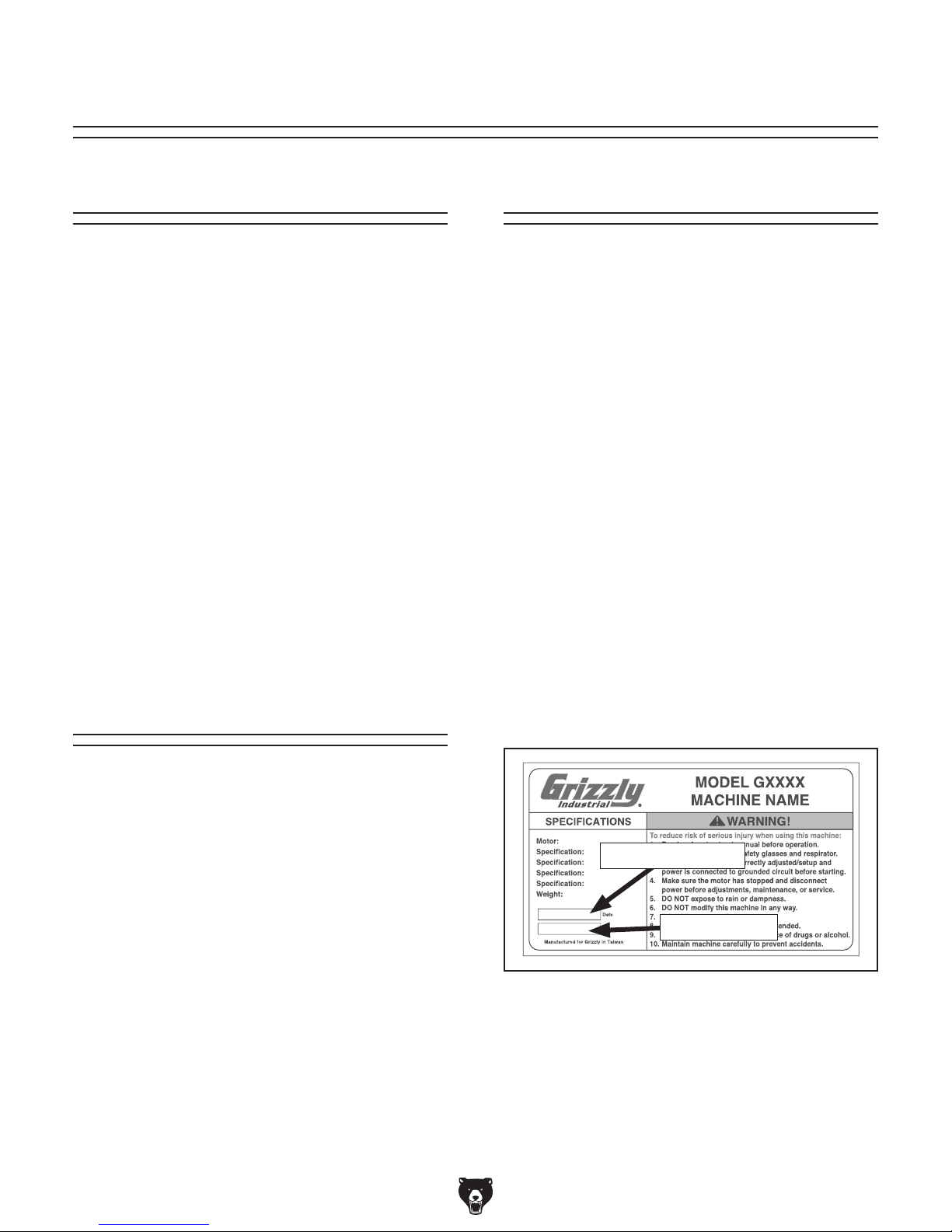
Manufacture Date and Serial Number
Machine Description
The Model G0686 is designed to sharpen the cutting edges and point angle of 2-flute, twisted large
drill bits from
5
⁄8" to 2" in diameter.
Manufacture Date
Serial Number
-2-
Model G0686 (Mfd. Since 01/15)
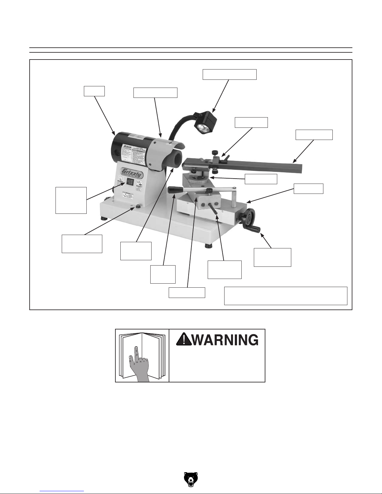
Identification
To reduce your risk of
serious injury, read this
entire manual BEFORE
LED Work Lamp
Motor
ON/OFF
Switch
Work Lamp
Switch
Motor
Wheel Guard
Grinding
Wheel
Pivot
Handle
Stop Rod
(1 of 2)
Tailstock*
Bit Carrier*
Jig Base*
Carriage
Carriage
Handwheel
Model G0686 (Mfd. Since 01/15)
Pivot Base
Figure 1. Model G0686 identification.
using machine.
* The tailstock, bit carrier, and jig base
are components of the jig assembly.
-3-

Controls &
Components
The jig assembly holds the drill bit at the selected height and horizontal/vertical angles during
operation.
Refer to Figure 2 and the descriptions below
to become familiar with the jig components and
controls.
Height Scale
Tailstock
Height
Set Screw
& Lock Lever
With the use of the pivot lever, the pivot base
moves the drill bit in a precise path across the
cutting edge of the grinding wheel.
The jig assembly and pivot base are mounted on
the carriage, which is moved toward or away from
the wheel with the use of the handwheel.
Refer to Figure 3 and the following descriptions to
become familiar with the pivot base and carriage
controls.
Stop Rod Lock Knob
Carriage
Handwheel
Flute
Pin
Angle
Scale
Bit Carrier
Figure 2. Jig assembly components and
controls.
Height Scale: Displays the correct setting for the
bit's diameter so that its center point is aligned
with the wheel center point.
Height Lock Lever: Secures the bit carrier at the
selected height and vertical angle.
Height Set Screw: Aligns the bit center point with
the wheel center point.
Flute Pin: Keeps the bit from rotating in the carrier from the rotational force of the wheel.
Pivot
Lever
Stop Rod
(1 of 2)
Figure 3. Pivot base and carriage controls.
Stop Rod Lock Knob: Secures the stop rod in
place.
Carriage Handwheel: Moves the drill bit toward
or away from the grinding wheel.
Pivot Lever: Moves the drill bit across the cutting
edge of the wheel in a precise path.
Stop Rod: When properly adjusted, safely limits
the travel of the drill bit across the wheel.
Tailstock: Keeps the bit from moving away from
the wheel during operation.
Angle Scale: Displays the combined angle of
both bit point angles that will be cut.
Bit Carrier: Keeps the bit steady with a V-type
trough configuration.
-4-
Model G0686 (Mfd. Since 01/15)

4.5A
Machine Data Sheet
Customer Service #: (570) 546-9663 · To Order Call: (800) 523-4777 · Fax #: (800) 438-5901
MODEL G0686
LARGE DRILL BIT GRINDER
Product Dimensions:
Weight ............................................................................................................................................................................. 75 lbs.
Width (side-to-side) x Depth (front-to-back) x Height .................................................................................15-1/2 x 25 x 19 in.
Footprint (Length/Width) ............................................................................................................................................11 x 20 in.
Shipping Dimensions:
Type ................................................................................................................................................................... Cardboard Box
Content .......................................................................................................................................................................... Machine
Weight .............................................................................................................................................................................. 77 lbs.
Length x Width x Height ...............................................................................................................................16-1/2 x 26 x 18 in.
Must Ship Upright .................................................................................................................................................................Yes
Electrical:
Power Requirement ........................................................................................................................ 110V, Single-Phase, 60 Hz
Full-Load Current Rating .....................................................................................................................................................
Minimum Circuit Size ........................................................................................................................................................... 15A
Connection Type ..................................................................................................................................................... Cord & Plug
Power Cord Included ............................................................................................................................................................Yes
Power Cord Length ...............................................................................................................................................................5 ft.
Power Cord Gauge .......................................................................................................................................................16 AWG
Plug Included ........................................................................................................................................................................Yes
Included Plug Type ..............................................................................................................................................................5-15
Switch Type ......................................................................................................................................................ON/OFF Rocker
Motor:
Main
Horsepower ............................................................................................................................................................1/2 HP
Phase .......................................................................................................................................................... Single-Phase
Amps ......................................................................................................................................................................... 4.5A
Speed ...............................................................................................................................................................6800 RPM
Type ............................................................................................................................................................. DC Universal
Number Of Speeds ..........................................................................................................................................................1
Power Transfer ............................................................................................................................................... Direct Drive
Bearings .....................................................................................................................Shielded and Permanently Sealed
Main Specifications:
Operation Information
Drill Bit Capacity ................................................................................................................................................5/8 – 2 in.
Miter Angle ................................................................................................................................................. 50 – 150 deg.
Grinder Wheel Sizes .................................................................... 60mm O.D. x 35mm I.D. x 65mm W. x M14-1.5 Bore
.....................................................................................................70mm O.D. x 54mm I.D. x 65mm W. x M14-1.5 Bore
Model G0686 (Mfd. Since 01/15)
-5-

Construction
Body ..........................................................................................................................................................................Steel
Slides .........................................................................................................................................................................Steel
Guide .........................................................................................................................................................................Steel
Paint ......................................................................................................................................................... Powder Coated
Other Specifications:
Country of Origin ............................................................................................................................................................. Taiwan
Warranty ........................................................................................................................................................................... 1 Year
Approximate Assembly & Setup Time ............................................................................................................................30 min.
Serial Number Location ..................................................................................................................................Machine ID Label
ISO 9001 Factory ................................................................................................................................................................... No
Certified by a Nationally Recognized Testing Laboratory (NRTL) ......................................................................................... No
Features: (Title Case)
Spiral Point Grinding Capability
Prism Clamp for Drill Grinding
Calibrated Infeed Handwheel
2-Axis Adjustable Center
16" Drill Tray
LED Work Light
-6-
Model G0686 (Mfd. Since 01/15)
SECTION 1: SAFETY
For Your Own Safety, Read Instruction
Manual Before Operating This Machine
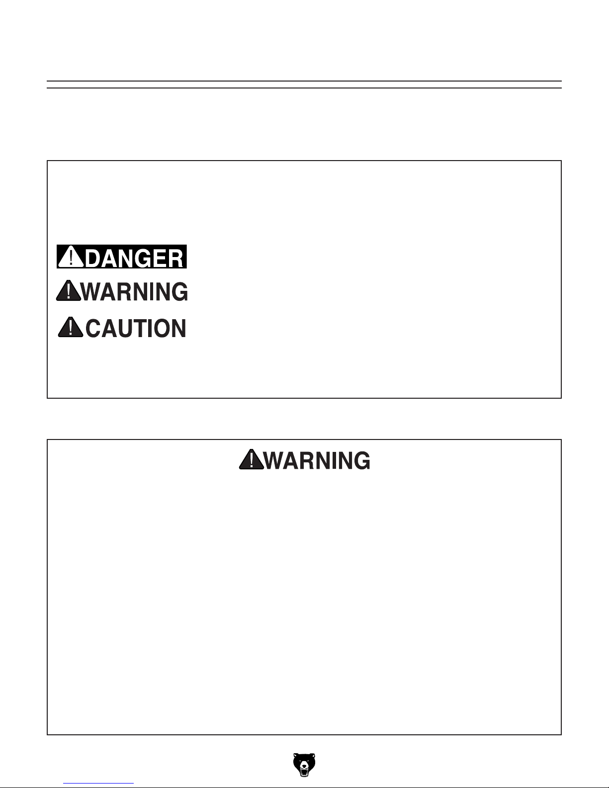
The purpose of safety symbols is to attract your attention to possible hazardous conditions.
This manual uses a series of symbols and signal words intended to convey the level of importance of the safety messages. The progression of symbols is described below. Remember that
safety messages by themselves do not eliminate danger and are not a substitute for proper
accident prevention measures. Always use common sense and good judgment.
Indicates an imminently hazardous situation which, if not avoided,
WILL result in death or serious injury.
Indicates a potentially hazardous situation which, if not avoided,
COULD result in death or serious injury.
Indicates a potentially hazardous situation which, if not avoided,
MAY result in minor or moderate injury. It may also be used to alert
against unsafe practices.
Alerts the user to useful information about proper operation of the
NOTICE
machine to avoid machine damage.
Safety Instructions for Machinery
OWNER’S MANUAL. Read and understand this
owner’s manual BEFORE using machine.
TRAINED OPERATORS ONLY. Untrained operators have a higher risk of being hurt or killed.
Only allow trained/supervised people to use this
machine. When machine is not being used, disconnect power, remove switch keys, or lock-out
machine to prevent unauthorized use—especially
around children. Make your workshop kid proof!
DANGEROUS ENVIRONMENTS. Do not use
machinery in areas that are wet, cluttered, or have
poor lighting. Operating machinery in these areas
greatly increases the risk of accidents and injury.
MENTAL ALERTNESS REQUIRED. Full mental
alertness is required for safe operation of machinery. Never operate under the influence of drugs or
alcohol, when tired, or when distracted.
ELECTRICAL EQUIPMENT INJURY RISKS.
You can be shocked, burned, or killed by touching
live electrical components or improperly grounded
machinery. To reduce this risk, only allow qualified
service personnel to do electrical installation or
repair work, and always disconnect power before
accessing or exposing electrical equipment.
DISCONNECT POWER FIRST.
nect machine from power supply BEFORE making adjustments, changing tooling, or servicing
machine. This prevents an injury risk from unintended startup or contact with live electrical components.
EYE PROTECTION. Always wear ANSI-approved
safety glasses or a face shield when operating or
observing machinery to reduce the risk of eye
injury or blindness from flying particles. Everyday
eyeglasses are NOT approved safety glasses.
Always discon-
Model G0686 (Mfd. Since 01/15)
-7-

WEARING PROPER APPAREL. Do not wear
clothing, apparel or jewelry that can become
entangled in moving parts. Always tie back or
cover long hair. Wear non-slip footwear to reduce
risk of slipping and losing control or accidentally
contacting cutting tool or moving parts.
HAZARDOUS DUST. Dust created by machinery
operations may cause cancer, birth defects, or
long-term respiratory damage. Be aware of dust
hazards associated with each workpiece material. Always wear a NIOSH-approved respirator to
reduce your risk.
HEARING PROTECTION. Always wear hearing protection when operating or observing loud
machinery. Extended exposure to this noise
without hearing protection can cause permanent
hearing loss.
REMOVE ADJUSTING TOOLS. Tools left on
machinery can become dangerous projectiles
upon startup. Never leave chuck keys, wrenches,
or any other tools on machine. Always verify
removal before starting!
USE CORRECT TOOL FOR THE JOB. Only use
this tool for its intended purpose—do not force
it or an attachment to do a job for which it was
not designed. Never make unapproved modifications—modifying tool or using it differently than
intended may result in malfunction or mechanical
failure that can lead to personal injury or death!
AWKWARD POSITIONS. Keep proper footing
and balance at all times when operating machine.
Do not overreach! Avoid awkward hand positions
that make workpiece control difficult or increase
the risk of accidental injury.
CHILDREN & BYSTANDERS. Keep children and
bystanders at a safe distance from the work area.
Stop using machine if they become a distraction.
GUARDS & COVERS. Guards and covers reduce
accidental contact with moving parts or flying
debris. Make sure they are properly installed,
undamaged, and working correctly BEFORE
operating machine.
FORCING MACHINERY. Do not force machine.
It will do the job safer and better at the rate for
which it was designed.
NEVER STAND ON MACHINE. Serious injury
may occur if machine is tipped or if the cutting
tool is unintentionally contacted.
STABLE MACHINE. Unexpected movement during operation greatly increases risk of injury or
loss of control. Before starting, verify machine is
stable and mobile base (if used) is locked.
USE RECOMMENDED ACCESSORIES. Consult
this owner’s manual or the manufacturer for recommended accessories. Using improper accessories will increase the risk of serious injury.
UNATTENDED OPERATION. To reduce the
risk of accidental injury, turn machine OFF and
ensure all moving parts completely stop before
walking away. Never leave machine running
while unattended.
MAINTAIN WITH CARE. Follow all maintenance
instructions and lubrication schedules to keep
machine in good working condition. A machine
that is improperly maintained could malfunction,
leading to serious personal injury or death.
DAMAGED PARTS. Regularly inspect machine
for damaged, loose, or mis-adjusted parts—or
any condition that could affect safe operation.
Immediately repair/replace BEFORE operating
machine. For your own safety, DO NOT operate
machine with damaged parts!
MAINTAIN POWER CORDS. When disconnecting cord-connected machines from power, grab
and pull the plug—NOT the cord. Pulling the cord
may damage the wires inside. Do not handle
cord/plug with wet hands. Avoid cord damage by
keeping it away from heated surfaces, high traffic
areas, harsh chemicals, and wet/damp locations.
EXPERIENCING DIFFICULTIES. If at any time
you experience difficulties performing the intended operation, stop using the machine! Contact our
Technical Support at (570) 546-9663.
-8-
Model G0686 (Mfd. Since 01/15)

Additional Safety for Drill Bit Grinders
necktie or loose clothing. Keep long hair away from
Move these types of materials a safe distance away.
The primary risks of operating a Drill Bit Grinder are as follows: You can be blinded or killed
by flying debris created by a chipped or damaged grinding wheel. Your fingers can be cut or
amputated by the rotating grinding wheel. You can also suffer crushing injuries from getting
hair, loose clothing, or jewelry entangled in the wheel. To reduce your risk of serious injury when
operating this machine, completely heed and understand the following.
PERFORM WHEEL INSPECTION. Before
installing a grinding wheel, visually check it for
cracks, chips, nicks or dents in the wheel surface.
Additionally, perform a “ring” test. Do not use the
wheel if it fails inspection.
USE UNDAMAGED WHEELS. Never use a wheel
that has been dropped or received a heavy blow,
even if there is no obvious damage.
SAFELY START UP GRINDER. To protect yourself, always stand to the side of the grinder until the
wheel reaches full speed. Allow it to run for at least
one minute before grinding. If a wheel is damaged,
it will usually fly apart shortly after startup.
USE CORRECT SPEED RATING. Wheels operated at a faster speed than rated for may break or
burst. Before mounting a new wheel, be sure wheel
RPM rating is equal to or higher than speed of
grinder. Never use unmarked wheels.
USE CORRECT WHEEL BORE. Only use wheel
with same bore as machine arbor.
AVOID TOUCHING MOVING WHEEL. Be aware
where your hands are relative to the grinding
wheel, and keep them away from wheel while
grinding.
USE DRILL BIT JIG. Always make sure the drill bit
is properly positioned in the jig, and the jig is firmly
secured to the base, and all locks are tight before
turning the machine ON.
DRY-GRIND ONLY. To avoid the risk of electrocution, do not use fluids of any kind with this
machine. This grinder is designed to perform drygrinding only!
WEAR PROPER CLOTHING. Do not wear gloves,
rotating grinding spindle.
WEAR PROPER PPE. Grinding ejects small particles at a high rate of speed. These particles
can cause blindness, skin injuries, or respiratory
damage. ALWAYS wear approved clothing, safety
goggles or safety glasses with side shields and
face shield, and a respirator appropriate for the
type of grinding to be done.
NEWLY GROUND DRILL BITS WILL BE HOT.
Drill bits can be sharp and get hot during grinding operations. Use leather gloves or shop rags to
protect your hands when installing or removing drill
bits. Remove the gloves before operating.
REDUCE RISK OF FIRE AND EXPLOSIONS.
This machine creates a shower of hot sparks that
can ignite explosive or flammable materials nearby.
PROPERLY MAINTAIN MACHINE. Keep machine
in proper working condition to help ensure all components work as intended and function safely.
Perform routine inspections and all necessary
maintenance, as indicated in owner’s manual.
Never operate machine with damaged or worn
parts that can break during operation.
Model G0686 (Mfd. Since 01/15)
-9-
SECTION 2: POWER SUPPLY
Before installing the machine, consider the availability and proximity of the required power supply
circuit. If an existing circuit does not meet the
requirements for this machine, a new circuit must
be installed. To minimize the risk of electrocution,
fire, or equipment damage, installation work and
electrical wiring must be done by an electrician or
qualified service personnel in accordance with all
applicable codes and standards.
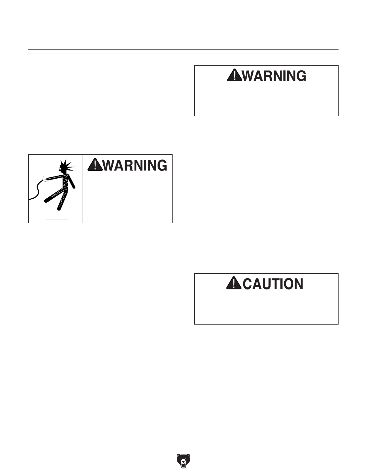
or equipment damage
may occur if machine is
not properly grounded
and connected to power
The full-load current rating is the amperage a
machine draws at 100% of the rated output power.
On machines with multiple motors, this is the
amperage drawn by the largest motor or sum of all
motors and electrical devices that might operate
at one time during normal operations.
The full-load current is not the maximum amount
of amps that the machine will draw. If the machine
is overloaded, it will draw additional amps beyond
the full-load rating.
If the machine is overloaded for a sufficient length
of time, damage, overheating, or fire may result—
especially if connected to an undersized circuit.
To reduce the risk of these hazards, avoid overloading the machine during operation and make
sure it is connected to a power supply circuit that
meets the specified circuit requirements.
For your own safety and protection of
Note: Circuit requirements in this manual apply to
a dedicated circuit—where only one machine will
be running on the circuit at a time. If machine will
be connected to a shared circuit where multiple
machines may be running at the same time, consult an electrician or qualified service personnel to
ensure circuit is properly sized for safe operation.
A power supply circuit includes all electrical
equipment between the breaker box or fuse panel
in the building and the machine. The power supply circuit used for this machine must be sized to
safely handle the full-load current drawn from the
machine for an extended period of time. (If this
machine is connected to a circuit protected by
fuses, use a time delay fuse marked D.)
This machine is prewired to operate on a power
supply circuit that has a verified ground and meets
the following requirements:
process. DO NOT connect to power until
Availability
Electrocution, fire, shock,
Serious injury could occur if you connect
machine to power before completing setup
instructed later in this manual.
110V Circuit Requirements
Nominal Voltage .................... 110V, 115 V, 120V
Cycle .......................................................... 60 Hz
Phase ........................................... Single-Phase
Power Supply Circuit ......................... 15 Amps
supply.
Full-Load Current Rating
Full-Load Current Rating at 110V .....4.5 Amps
-10 -
property, consult an electrician if you are
unsure about wiring practices or electrical
codes in your area.
Model G0686 (Mfd. Since 01/15)

Improper connection of the equipment-grounding
wire can result in a risk of electric shock. The
wire with green insulation (with or without yellow
stripes) is the equipment-grounding wire. If repair
or replacement of the power cord or plug is necessary, do not connect the equipment-grounding
wire to a live (current carrying) terminal.
Check with a qualified electrician or service personnel if you do not understand these grounding
requirements, or if you are in doubt about whether
the tool is properly grounded. If you ever notice
that a cord or plug is damaged or worn, disconnect it from power, and immediately replace it with
a new one.
We do not recommend using an extension cord
with this machine.
cord, only use it if absolutely necessary and only
on a temporary basis.
Extension cords cause voltage drop, which can
damage electrical components and shorten motor
life. Voltage drop increases as the extension cord
size gets longer and the gauge size gets smaller
(higher gauge numbers indicate smaller sizes).
Any extension cord used with this machine must
be in good condition and contain a ground wire
and matching plug/receptacle. Additionally, it must
meet the following size requirements:
Grounding & Plug Requirements
it will not fit the outlet, have a qualified
electrician install the proper outlet with a
This machine MUST be grounded. In the event
of certain malfunctions or breakdowns, grounding
reduces the risk of electric shock by providing a
path of least resistance for electric current.
This machine is equipped with a power cord that
has an equipment-grounding wire and a grounding
plug. Only insert plug into a matching receptacle
(outlet) that is properly installed and grounded in
accordance with all local codes and ordinances.
DO NOT modify the provided plug!
GROUNDED
5-15 RECEPTACLE
Grounding Pin
5-15 PLUG
Extension Cords
If you must use an extension
Neutral Hot
Figure 4. Typical 5-15 plug and receptacle.
SHOCK HAZARD!
Two-prong outlets do not meet the grounding
requirements for this machine. Do not modify
or use an adapter on the plug provided—if
verified ground.
Model G0686 (Mfd. Since 01/15)
Minimum Gauge Size ...........................14 AWG
Maximum Length (Shorter is Better).......50 ft.
-11-
SECTION 3: SETUP
This machine was carefully packaged for safe
transport. When unpacking, separate all enclosed
items from packaging materials and inspect them
for shipping damage.
,
please
IMPORTANT:
you are completely satisfied with the machine and
have resolved any issues between Grizzly or the
shipping agent. You MUST have the original pack-
aging to file a freight claim. It is also extremely
helpful if you need to return your machine later.
The following is a list of items shipped with your
machine. Before beginning setup, lay these items
out and inventory them.
If any non-proprietary parts are missing (e.g. a
nut or a washer), we will gladly replace them; or
for the sake of expediency, replacements can be
obtained at your local hardware store.
This machine presents
serious injury hazards
to untrained users. Read
through this entire manual to become familiar with
the controls and operations before starting the
machine!
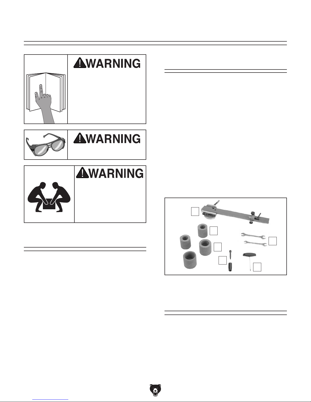
Box 1 (Figure 5) Qty
Wear safety glasses during
the entire setup process!
This machine and its components are very heavy.
Get lifting help and use
safe lifting and moving
methods when handling
heavy machinery.
A. G0686 Grinder (Not Shown)....................... 1
B. Bit Carrier & Tailstock Assembly ................ 1
C. Combo Wrenches 8/10, 14/17mm .....1 Each
D. Small Grinding Wheels 60-Grit .................. 2
E. Extra-Large Grinding Wheels 60-Grit ........ 2
F. Handwheel Handle & Cap Screw ......1 Each
G. T-Handle Hex Wrench 3mm ....................... 1
Inventory
B
Unpacking
If items are damaged
call us immediately at (570) 546-9663.
Save all packaging materials until
-12-
D
C
E
F
G
Figure 5. Model G0686 loose inventory.
Needed for Setup
The following items are needed, but not included,
for the setup/assembly of this machine.
Description Qty
• Additional People ....................................... 1
• Safety Glasses ........................................... 1
• Hex Wrench 5mm ....................................... 1
• Cleaner/Degreaser ..................... As Needed
• Disposable Shop Rags ............... As Needed
Model G0686 (Mfd. Since 01/15)
 Loading...