

Page 1

MODEL G0675
10" JOINTER/PLANER
COMBO MACHINE
OWNER'S MANUAL
COPYRIGHT © NOVEMBER, 2008 BY GRIZZLY INDUSTRIAL, INC., REVISED SEPTEMBER, 2013 (ST)
WARNING: NO PORTION OF THIS MANUAL MAY BE REPRODUCED IN ANY SHAPE
OR FORM WITHOUT THE WRITTEN APPROVAL OF GRIZZLY INDUSTRIAL, INC.
#BL11208 PRINTED IN CHINA
Page 2

This manual provides critical safety instructions on the proper setup,
operation, maintenance, and service of this machine/tool. Save this
document, refer to it often, and use it to instruct other operators.
Failure to read, understand and follow the instructions in this manual
may result in fire or serious personal injury—including amputation,
electrocution, or death.
The owner of this machine/tool is solely responsible for its safe use.
This responsibility includes but is not limited to proper installation in
a safe environment, personnel training and usage authorization,
proper inspection and maintenance, manual availability and comprehension, application of safety devices, cutting/sanding/grinding tool
integrity, and the usage of personal protective equipment.
The manufacturer will not be held liable for injury or property damage
from negligence, improper training, machine modifications or misuse.
Some dust created by power sanding, sawing, grinding, drilling, and
other construction activities contains chemicals known to the State
of California to cause cancer, birth defects or other reproductive
harm. Some examples of these chemicals are:
• Lead from lead-based paints.
• Crystalline silica from bricks, cement and other masonry products.
• Arsenic and chromium from chemically-treated lumber.
Your risk from these exposures varies, depending on how often you
do this type of work. To reduce your exposure to these chemicals:
Work in a well ventilated area, and work with approved safety equipment, such as those dust masks that are specially designed to filter
out microscopic particles.
Page 3

Table of Contents
INTRODUCTION ............................................... 2
Manual Accuracy ........................................... 2
Contact Info.................................................... 2
Functional Overview ...................................... 2
Identification ................................................... 3
Machine Data Sheet ...................................... 4
SECTION 1: SAFETY ....................................... 6
Safety Instructions for Machinery .................. 6
Additional Safety Instructions for Jointers ..... 8
Additional Safety Instructions for Planers ...... 9
SECTION 2: CIRCUIT REQUIREMENTS ...... 10
220V Operation ............................................ 10
SECTION 3: SETUP ....................................... 11
Items Needed for Setup ............................... 11
Unpacking .................................................... 11
Inventory ...................................................... 12
Clean Up ...................................................... 12
Site Considerations ...................................... 13
Moving & Placing Base Unit ........................ 13
Mounting to Shop Floor ............................... 14
Assembly ..................................................... 15
Dust Collection ............................................. 16
Setting Outfeed Table Height ...................... 17
Test Run ...................................................... 18
Recommended Adjustments ........................ 19
Belt Break-In ................................................ 19
SECTION 4: OPERATIONS ........................... 20
Basic Jointer Controls .................................. 20
Basic Planer Controls .................................. 22
Jointer-Planer Conversion ........................... 22
Stock Inspection and Requirements ............ 24
Squaring Stock............................................. 25
Surface Planing............................................ 26
Edge Jointing ............................................... 28
Bevel Cutting................................................ 29
Thickness Planer Operation ........................ 30
SECTION 6: MAINTENANCE ......................... 32
Schedule ...................................................... 32
Cleaning ....................................................... 32
Belts ............................................................. 32
Lubrication ................................................... 34
SECTION 7: SERVICE ................................... 37
Troubleshooting ........................................... 37
Jointer Table Parallelism ............................. 39
Inspecting Knives ......................................... 42
Adjusting/Replacing Knives ......................... 43
Setting Fence Stops .................................... 44
Spring Tension ............................................. 46
Replacing Feed Rollers ............................... 47
Chain Tension .............................................. 48
Planer Table Parallelism .............................. 49
Anti-Kickback Fingers .................................. 51
SECTION 8: WIRING ...................................... 52
Wiring Safety Instructions ............................ 52
Wiring Overview ........................................... 53
ON/OFF Switch Assembly Wiring ................ 54
Components Wiring ..................................... 55
SECTION 9: PARTS ....................................... 56
Table Breakdown ......................................... 56
Motor Assembly Breakdown ........................ 57
Frame Breakdown........................................ 58
Fence Assembly Breakdown ....................... 59
Feed Gear Assembly Breakdown ................ 60
Cutterhead-Feed Rollers Breakdown .......... 62
Access Panels Breakdown .......................... 63
Base Breakdown .......................................... 64
Planer Table Breakdown ............................. 65
Labels and Cosmetic Parts .......................... 66
WARRANTY AND RETURNS ........................ 69
SECTION 5: ACCESSORIES ......................... 31
Page 4

INTRODUCTION
Manual Accuracy
We are proud to offer this manual with your new
machine! We've made every effort to be exact
with the instructions, specifications, drawings, and
photographs of the machine we used when writing this manual. However, sometimes errors do
happen and we apologize for them.
Also, owing to our policy of continuous improvement, your machine may not exactly match
the manual. If you find this to be the case, and
the difference between the manual and machine
leaves you in doubt, immediately call our technical support for updates or clarification.
For your convenience, we always keep current
Grizzly manuals and most updates available on
our website at www.grizzly.com. Any updates to
your machine will be reflected in these documents
as soon as they are complete. Visit our site often
to check for the latest updates!
Contact Info
We stand behind our machines. If you have any
service questions, parts requests or general questions about the machine, please call or write us at
the location listed below.
Grizzly Industrial, Inc.
1203 Lycoming Mall Circle
Muncy, PA 17756
Phone: (570) 546-9663
Fax: (800) 438-5901
E-Mail: techsupport@grizzly.com
If you have any comments regarding this manual,
please write to us at the address below:
C
/O Technical Documentation Manager
Grizzly Industrial, Inc.
P.O. Box 2069
Bellingham, WA 98227-2069
Email: manuals@grizzly.com
Functional Overview
This jointer/planer can flatten the face or edge of
rough and warped stock, and reduce the thickness of workpieces.
This jointer/planer shares a single cutterhead,
which features two steel knives that remove the
bottom face of the workpiece in jointer mode or
the top surface of the workpiece in planer mode.
The key features of the jointer are the outfeed and
infeed tables and fence, and the main features of
the planer are the planing table and the powered
feed rollers.
To square up a piece of rough stock, the infeed
table is lowered a desired amount. The stock is
placed firmly on the jointer infeed table and against
the fence. While using the fence as a guide, the
workpiece is moved over the cutterhead, where the
knives make numerous shallow cuts that “shave”
off the surface of the workpiece. The workpiece
is received by the outfeed table, which along
with the fence, continue to guide the workpiece
across a flat plane until it completely passes the
cutterhead. This process is repeated a number of
times to yield the desired cut.
After the machine is converted to planer mode,
the operator adjusts the table height according
to the stock thickness and the desired depth of
cut. The face of the previously squared-up stock
is placed on the table, the workpiece is pushed
into the machine, where the infeed roller grabs
it and draws it into the cutterhead knives. The
powered outfeed roller pulls the workpiece out of
the cutterhead and delivers it to the outfeed table.
This process is repeated until the board is smooth
on one side. The board can be flipped over again
and planed on the other side until it is smooth, or it
can be edge joined after the machine is converted
back to a jointer.
-2-
G0675 10" Jointer/Planer Combo Machine
Page 5
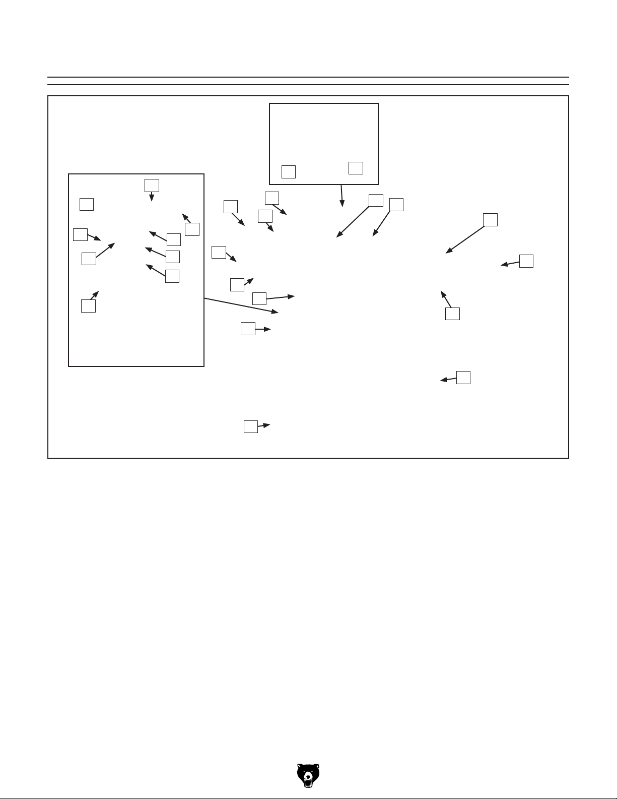
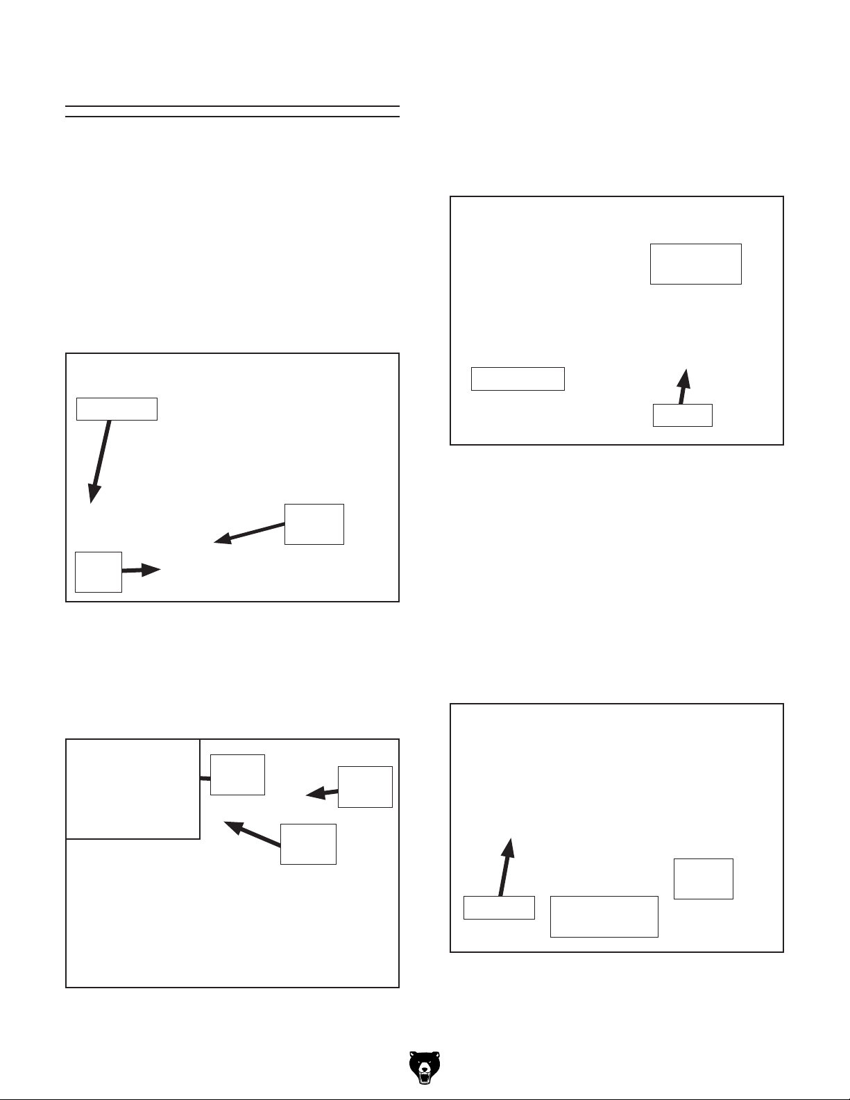
Identification
B
P
O
N
M
L
Q
R
S
T
X
W
V
A
Y
U
K
J
C
D
E
F
G
H
I
A. Fence
B. Fence Height Lock Knob
C. Fence Tilt Lock
D. Blade Guard Lock Knob
E. Blade Guard
F. Infeed Table
G. Fence Lock Lever
H. Infeed Table Adjustment Lever
I. Base
J. Foot
K. Front Access Panel
L. Planer Table Height Handwheel
Figure 1. G0675 identification.
M. Planer Table
N. Rear Access Panel
O. Outfeed Table Lock Arm
P. Dust Chute Assembly (Planer Operations)
Q. Dust Chute Lock
R. Outfeed Table Lock
S. Planer Table Height Indicator
T. Planer Table Height Scale
U. On/Off Switch
V. 4" Dust Port (Jointer Operations)
W. Blade Guard Arm Lock Lever
X. Blade Guard Arm Adjustment Knob
Y. Outfeed Table
G0675 10" Jointer/Planer Combo Machine
-3-
Page 6

Machine Data Sheet
mACHINe dATA
SHeeT
Customer Service #: (570) 546-9663 • To Order Call: (800) 523-4777 • Fax #: (800) 438-5901
model G0675
JoINTeR/PlANeR ComBINATIoN mACHINe
Product Dimensions:
Weight .............................................................................................................................................................317 lbs.
Length/Width/Height ............................................................................................................................46" x 27" x 38"
Foot Print (Length/Width) ...............................................................................................................................26" x 22"
Shipping Dimensions:
Carton #1
Type ................................................................................................................................................ Wood Crate
Content ..................................................................................................................................................Machine
Weight ....................................................................................................................................................348 lbs.
Length/Width/Height .................................................................................................................. 44" x 25" x 25"
Carton #2
Type .................................................................................................................................................. Cardboard
Content ....................................................................................................................................................... Base
Weight ......................................................................................................................................................30 lbs.
Length/Width/Height .................................................................................................................... 29" x 14" x 7"
Electrical:
Switch ................................................................................................................................................... On/Off Buttons
Switch Voltage .....................................................................................................................................................220V
Recommended Cord Gauge ........................................................................................................................ 14 Gauge
Recommended Breaker Size ................................................................................................................................ 15A
Plug ............................................................................................................................................................NEMA 6-15
Motors:
Main
Type ................................................................................................................. TEFC Capacitor Start Induction
Horsepower ............................................................................................................................................. 2.5 HP
Voltage ....................................................................................................................................................... 220V
Phase ....................................................................................................................................................... Single
Amps ........................................................................................................................................................... 9.9A
Speed ................................................................................................................................................ 3400 RPM
Cycle .........................................................................................................................................................60 Hz
Number Of Speeds .......................................................................................................................................... 1
Power Transfer ................................................................................................................................ Poly V-Belt
Bearings ...................................................................................................................... Shielded and Lubricated
Main Specifications:
Fence Information
Fence Length ............................................................................................................................................35
Fence Height ................................................................................................................................................5
Fence Stops ............................................................................................................................... 45 and 90 deg.
Cutting Capacities (Jointer)
Bevel Jointing ..................................................................................................................................... 0-45 deg.
Maximum Width of Cut ..............................................................................................................................10
Maximum Depth of Cut ..................................................................................................................................
Number of Cuts Per Minute ..................................................................................................................... 13000
7
/16"
7
/8"
1
/4"
1
/8"
-4-
G0675 10" Jointer/Planer Combo Machine
Page 7

Cutting Capacities (Planer)
3
Maximum Width of Cut ................................................................................................................................9
Maximum Depth of Cut Planing Full Width ...................................................................................................
3
/4"
/16"
Number of Cuts Per Minute ..................................................................................................................... 13000
Number of Feed Speeds .................................................................................................................................. 1
Feed Speed ...........................................................................................................................................16 FPM
Minimum Stock Length ........................................................................................................................... 11
Maximum Stock Thickness ..........................................................................................................................8
13
/16"
1
/4"
Knife Information (Jointer)
Number of Knives ............................................................................................................................................ 2
Knife Type ................................................................................................................................................... HSS
Knife Length. ..............................................................................................................................................10
Knife Width. .................................................................................................................................................
Knife Thickness. .............................................................................................................................................
1
/4"
11
/16"
1
/8"
Knife Adjustment. ........................................................................................................................... Jack Screws
Cutterhead Information
Cutterhead Type ..........................................................................................................................2 HSS Knives
Cutterhead Diameter ...................................................................................................................................2
9
/32"
Cutterhead Speed ............................................................................................................................. 6500 RPM
Table Information (Jointer)
Table Length ........................................................................................................................................... 40
Table Width ................................................................................................................................................12
Floor To Table Height ................................................................................................................................33
15
/16"
1
/2"
3
/4"
Table Information (Planer)
Table Length ..............................................................................................................................................23
Table Width ..................................................................................................................................................9
Table Thickness ...........................................................................................................................................1
1
/8"
3
/4"
1
/2"
Floor To Table Height .............................................................................................................................23"-30"
Construction
Body Assembly Construction .......................................................................................................... Sheet Metal
Cutterhead Assembly Construction ........................................................................................................... Steel
Infeed Roller Construction ........................................................................ Steel w/Vulcanized Rubber Coating
Outfeed Roller Construction ...................................................................... Steel w/Vulcanized Rubber Coating
Jointer Table Construction ...................................................................................................................Cast Iron
Paint. ......................................................................................................................................... Powder Coated
Other Infomation
Dust Port Size ................................................................................................................................................. 4"
Number of Dust Ports ...................................................................................................................................... 1
Measurement Scale (Jointer) ....................................................................................................................... mm
Measurement Scale (Planer) ....................................................................................................................... mm
Other Specifications:
Country Of Origin ................................................................................................................................................ China
Warranty .............................................................................................................................................................1 Year
Serial Number Location ...............................................................................................ID Label on Front of the Stand
Features:
Quick release fence
Flip up outfeed table and change lever simplify jointer-planer conversion
Vulcanized rubber feed rollers (planer mode)
Heavy duty cast iron infeed and outfeed tables, easily and accurately adjustable
Cutterhead guard adjustable for workpiece height
Dust hood position adjustable for jointer or planer conversion
G0675 10" Jointer/Planer Combo Machine
-5-
Page 8
SECTION 1: SAFETY
For Your Own Safety, Read Instruction
Manual Before Operating this Machine
The purpose of safety symbols is to attract your attention to possible hazardous conditions. This
manual uses a series of symbols and signal words intended to convey the level of importance
of the safety messages. The progression of symbols is described below. Remember that safety
messages by themselves do not eliminate danger and are not a substitute for proper accident
prevention measures.
Indicates an imminently hazardous situation which, if not avoided,
WILL result in death or serious injury.
Indicates a potentially hazardous situation which, if not avoided,
COULD result in death or serious injury.
Indicates a potentially hazardous situation which, if not avoided,
MAY result in minor or moderate injury. It may also be used to alert
against unsafe practices.
This symbol is used to alert the user to useful information about
NOTICE
proper operation of the machine.
Safety Instructions for Machinery
OWNER’S MANUAL. Read and understand
this owner’s manual BEFORE using machine.
Untrained users can be seriously hurt.
EYE PROTECTION. Always wear ANSIapproved safety glasses or a face shield when
operating or observing machinery. to reduce
the risk of eye injury or blindness from flying particles Everyday eyeglasses are not
approved safety glasses.
HAZARDOUS DUST. Dust created while using
machinery may cause cancer, birth defects,
or long-term respiratory damage. Be aware of
dust hazards associated with each workpiece
material, and always wear a NIOSH-approved
respirator to reduce your risk.
WEARING PROPER APPAREL. Do not wear
clothing, apparel, or jewelry that can become
entangled in moving parts. Always tie back or
cover long hair. Wear non-slip footwear to avoid
accidental slips which could cause a loss of
workpiece control.
HEARING PROTECTION. Always wear hearing protection when operating or observiing loud
machinery. Extended exposure to this noise
without hearing protection can cause permanent
hearing loss.
MENTAL ALERTNESS. Be mentally alert when
running machinery. Never operate under the
influence of drugs or alcohol, when tired, or when
distracted.
-6-
G0675 10" Jointer/Planer Combo Machine
Page 9

Safety Instructions for Machinery
DISCONNECTING POWER SUPPLY. Always
disconnect machine from power supply before
servicing, adjusting, or changing cutting tools
(bits, blades, cutters, etc.). Make sure switch is
in OFF position before reconnecting to avoid an
unexpected or unintentional start.
INTENDED USE. Only use the machine for its
intended purpose and only use recommended
accessories. Never stand on machine, modify
it for an alternative use, or outfit it with nonapproved accessories.
STABLE MACHINE. Unexpected movement
during operations greatly increases the risk of
injury and loss of control. Verify machines are
stable/secure and mobile bases (if used) are
locked before starting.
FORCING MACHINERY. Do not force machine.
It will do the job safer and better at the rate for
which it was designed.
GUARDS & COVERS. Guards and covers can
protect you from accidental contact with moving parts or flying debris. Make sure they are
properly installed, undamaged, and working
correctly before using machine.
REMOVING TOOLS. Never leave adjustment
tools, chuck keys, wrenches, etc. in or on
machine—especially near moving parts. Verify
removal before starting!
AWKWARD POSITIONS. Keep proper footing and balance at all times when operating
machine. Do not overreach! Avoid awkward
hand positions that make workpiece control difficult or increase the risk of accidental injury.
DANGEROUS ENVIRONMENTS. Do not use
machinery in wet locations, cluttered areas,
around flammables, or in poorly-lit areas. Keep
work area clean, dry, and well lighted to minimize risk of injury.
APPROVED OPERATION. Untrained operators
can be seriously hurt by machinery. Only allow
trained or properly supervised people to use
machine. When machine is not being used, disconnect power, remove switch keys, or lock-out
machine to prevent unauthorized use—especially
around children. Make workshop kid proof!
CHILDREN & BYSTANDERS. Keep children
and bystanders a safe distance away from work
area. Stop using machine if children or bystanders become a distraction.
FEED DIRECTION. Unless otherwise noted, feed
work against the rotation of blades or cutters.
Feeding in the same direction of rotation may pull
your hand into the cut.
SECURING WORKPIECE. When required, use
clamps or vises to secure workpiece. A secured
workpiece protects hands and frees both of them
to operate the machine.
UNATTENDED OPERATION. Never leave
machine running while unattended. Turn machine
Off and ensure all moving parts completely stop
before walking away.
MAINTENANCE & INSPECTION. A machine that
is not properly maintained may operate unpredictably. Follow all maintenance instructions and
lubrication schedules to keep machine in good
working condition. Regularly inspect machine for
loose bolts, alignment of critical parts, binding, or
any other conditions that may affect safe operation. Always repair or replace damaged or misadjusted parts before operating machine.
EXPERIENCING DIFFICULTIES. If at any time
you are experiencing difficulties performing the
intended operation, stop using the machine!
Contact our Technical Support Department at
(570) 546-9663.
G0675 10" Jointer/Planer Combo Machine
-7-
Page 10
Additional Safety Instructions for Jointers
1. JOINTER KICKBACK. "Kickback" is when
the workpiece is thrown off the jointer table
by the force of the cutterhead. Always use
push blocks and safety glasses to reduce
the likelihood of injury from “kickback.” If
you do not understand what kickback is,
or how it occurs, DO NOT operate this
machine.
2. CUTTERHEAD ALIGNMENT. Keep the top
edge of the outfeed table aligned with the
cutterhead knife at top dead center (TDC)
to avoid kickback and personal injuries.
3. PUSH BLOCKS. Always use push blocks
whenever surface planing. Never pass your
hands directly over the cutterhead without a
push block.
4. WORKPIECE SUPPORT. Supporting the
workpiece adequately at all times while
cutting is crucial for making safe cuts and
avoiding injury. Never attempt to make a cut
with an unstable workpiece.
5. KICKBACK ZONE. The "kickback zone"
is the path directly through the end of the
infeed table. Never stand or allow others to
stand in this area during operation.
7. CUTTING LIMITATIONS. The jointer may
kick out a workpiece at the operator or be
damaged if pushed beyond these limits.
1
• Maximum Depth of Cut ......................
• Maximum Width of Cut .................. 10
⁄8"
1
⁄4"
• Minimum Length ...............................12"
8. JOINTING WITH THE GRAIN. Jointing against
the grain or jointing end grain is dangerous
and could produce chatter or excessive chipout. Always joint with the grain.
9. KEEPING GUARDS IN PLACE. All opera-
tions must be performed with the cutterhead
guard in place.
10. PROPER CUTTING. When cutting, always
keep the workpiece moving toward the outfeed
table until the workpiece has passed completely over the cutterhead. Never back the
work toward the infeed table.
11. USING GOOD STOCK. Jointing safety begins
with your lumber. Inspect your stock carefully
before you feed it over the cutterhead. Never
joint a board that has loose knots, nails, or
staples. If you have any doubts about the stability or structural integrity of your stock, DO
NOT joint it!
6. MAXIMUM CUTTING DEPTH. The maxi-
mum cutting depth for one pass is
1
Never attempt any single cut deeper than
this!
Like all machines there is danger associated
with this machine. Accidents are frequently
caused by lack of familiarity or failure to pay
attention. Use this machine with respect
and caution to lessen the possibility of
operator injury. If normal safety precautions
are overlooked or ignored, serious personal
injury may occur.
-8-
⁄8".
No list of safety guidelines can be complete.
Every shop environment is different. Always
consider safety first, as it applies to your
individual working conditions. Use this and
other machinery with caution and respect.
Failure to do so could result in serious personal injury, damage to equipment, or poor
work results.
G0675 10" Jointer/Planer Combo Machine
Page 11

Additional Safety Instructions for Planers
1. KICKBACK. "Kickback" is when the workpiece
is thrown off the planer table by the force of
the cutterhead. If you do not understand
what kickback is, or how it occurs, DO NOT
operate this machine.
2. REACHING INSIDE PLANER. Never reach
inside the planer or remove covers when the
planer is connected to power.
3. INFEED CLEARANCE SAFETY. The infeed
roller is designed to pull material into the
cutterhead. Always keep hands, clothing,
and long hair away from the infeed roller during operation to prevent serious injury.
4. BODY POSITION WHILE OPERATING. The
workpiece may kick out during operation.
To avoid getting hit, stand to the side of the
planer during the entire operation.
5. PLANING CORRECT MATERIAL. Only
plane natural wood stock with this planer.
DO NOT plane MDF, plywood, laminates, or
other synthetic products.
8. CUTTING LIMITATIONS. The planer may
kick out a workpiece at the operator or be
damaged if pushed beyond these limits.
3
• Maximum Depth of Cut .....................
• Maximum Width of Cut ..................9
⁄16"
27
⁄32"
• Minimum Board Length ..................... 12"
1
• Maximum Board Thickness ............. 8
⁄4"
9. CLEAN STOCK. Only plane clean stock.
Planing stock with nails, staples, or imbedded stone will damage your knives and may
cause a fire hazard if the dust collector captures sparks or hot particles that have contacted the knives. Always thoroughly inspect
and prepare stock to avoid these hazards.
10. REMOVING JAMMED WORKPIECES. To
avoid serious injury, always stop the planer and disconnect power before removing
jammed workpieces.
11. DULL/DAMAGED KNIVES. The planer may
kick out a workpiece at the operator or give
poor finish results if it is operated with dull or
damaged knives.
6. GRAIN DIRECTION. Planing across the
grain is hard on the planer and may cause
the workpiece to kick out. Always plane in
the same direction or at a slight angle with
the wood grain.
7. LOOKING INSIDE PLANER. Wood chips
fly around inside the planer at a high rate
of speed. DO NOT look inside the planer or
remove guards/covers when the planer is
connected to power or during operation.
12. UNPLUGGING DURING ADJUSTMENTS.
When connected to power, the planer can
be accidentally turned ON. Always disconnect power when servicing or adjusting the
components of the planer.
13. WORKPIECE CLEARANCE. Always verify
workpiece has enough room to exit the planer before starting.
G0675 10" Jointer/Planer Combo Machine
-9-
Page 12
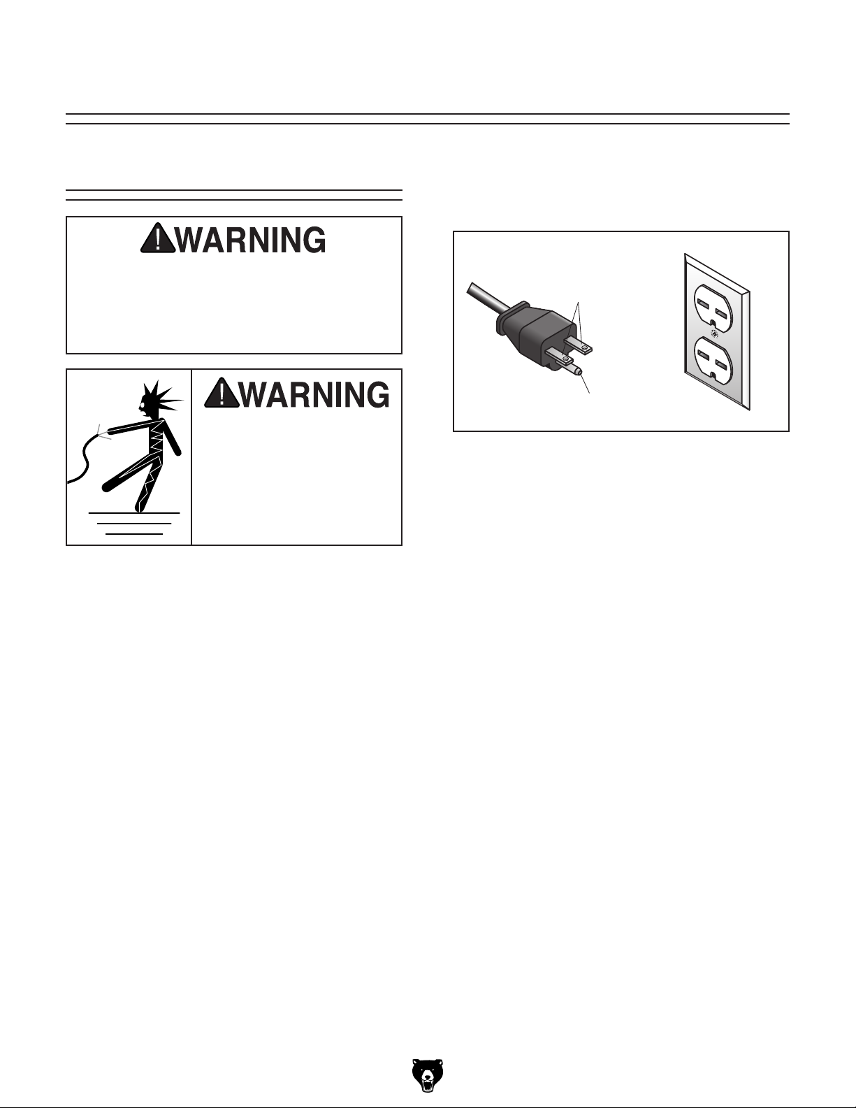
Grounding Prong
Current Carrying Prongs
6-15 PLUG
GROUNDED
6-15 RECEPTACLE
SECTION 2: CIRCUIT REQUIREMENTS
220V Operation
Serious personal injury could occur if you
connect the machine to power before completing the setup process. DO NOT connect
the machine to the power until instructed
later in this manual.
Electrocution or fire could
result if machine is not
grounded and installed in
compliance with electrical
codes. Compliance MUST
be verified by a qualified
electrician!
Power Connection Device
The Model G0675 comes with a 6-15 plug, similar
to Figure 2 to connect the machine to power.
Figure 2. NEMA 6-15 plug and receptacle.
Extension Cords
Using extension cords may reduce the life of the
motor. Instead, place the machine near a power
source. If you must use an extension cord:
Full Load Amperage Draw
This machine draws the following amps under
maximum load:
Amp Draw ............................................. 9.9 Amps
Power Supply Circuit Requirements
The power supply circuit for your machine MUST
be grounded and rated for the amperage given
below. Never replace a circuit breaker on an existing circuit with one of higher amperage without
consulting a qualified electrician to ensure compliance with wiring codes. If you are unsure about
the wiring codes in your area or you plan to
connect your machine to a shared circuit, consult a qualified electrician.
Minimum Circuit Size ............................. 15 Amps
• Use at least a 14 gauge cord that does not
exceed 50 feet in length!
• The extension cord must also have a ground
wire and plug pin.
• A qualified electrician MUST size cords over
50 feet long to prevent motor damage.
-10 -
G0675 10" Jointer/Planer Combo Machine
Page 13
SECTION 3: SETUP
Items Needed for
This machine presents
serious injury hazards
to untrained users. Read
through this entire manual to become familiar with
the controls and operations before starting the
machine!
Wear safety glasses during the entire setup process!
This machine and its components are very heavy.
Get lifting help or use
power lifting equipment
such as a forklift to move
heavy items.
Setup
The following items are needed to complete the
setup process, but are not included with your
machine:
Description Qty
• Safety Glasses for Each Person ................ 1
• Power Lifting Equipment ............................ 1
• Dust Collection System .............................. 1
• 4" Dust Hose (length as needed) ............... 1
• 4" Hose Clamp ........................................... 1
• Shop Rags and Cleaning Solvent ...... Varies
• Wrench 16mm ............................................ 1
• Precision Level ........................................... 1
• Lifting Help/Assistant .................................. 1
Unpacking
Your machine was carefully packaged for safe
transportation. Remove the packaging materials
from around your machine and inspect it. If you
discover the machine is damaged, please imme-
diately call Customer Service at (570) 546-9663
for advice.
G0675 10" Jointer/Planer Combo Machine
Save the containers and all packing materials for
possible inspection by the carrier or its agent.
Otherwise, filing a freight claim can be difficult.
When you are completely satisfied with the condition of your shipment, inventory the contents.
-11-
Page 14
Inventory
Clean Up
The following is a description of the main components shipped with your machine. Lay the components out to inventory them.
Note: If you can't find an item on this list, check
the mounting location on the machine or examine
the packaging materials carefully. Occasionally
we pre-install certain components for shipping
purposes.
Box 1: (Figure 3) Qty
A. Jointer/Planer Unit (not shown) .................. 1
B. Fence Assembly ......................................... 1
C. Blade Guard Arm Assembly ....................... 1
D. Blade Guard ............................................... 1
E. Blade Adjustment Gauge ........................... 1
F. Dust Port .................................................... 1
G. Hex Wrench 5mm ....................................... 1
H. Wrench 8/10mm ......................................... 1
C
D
E
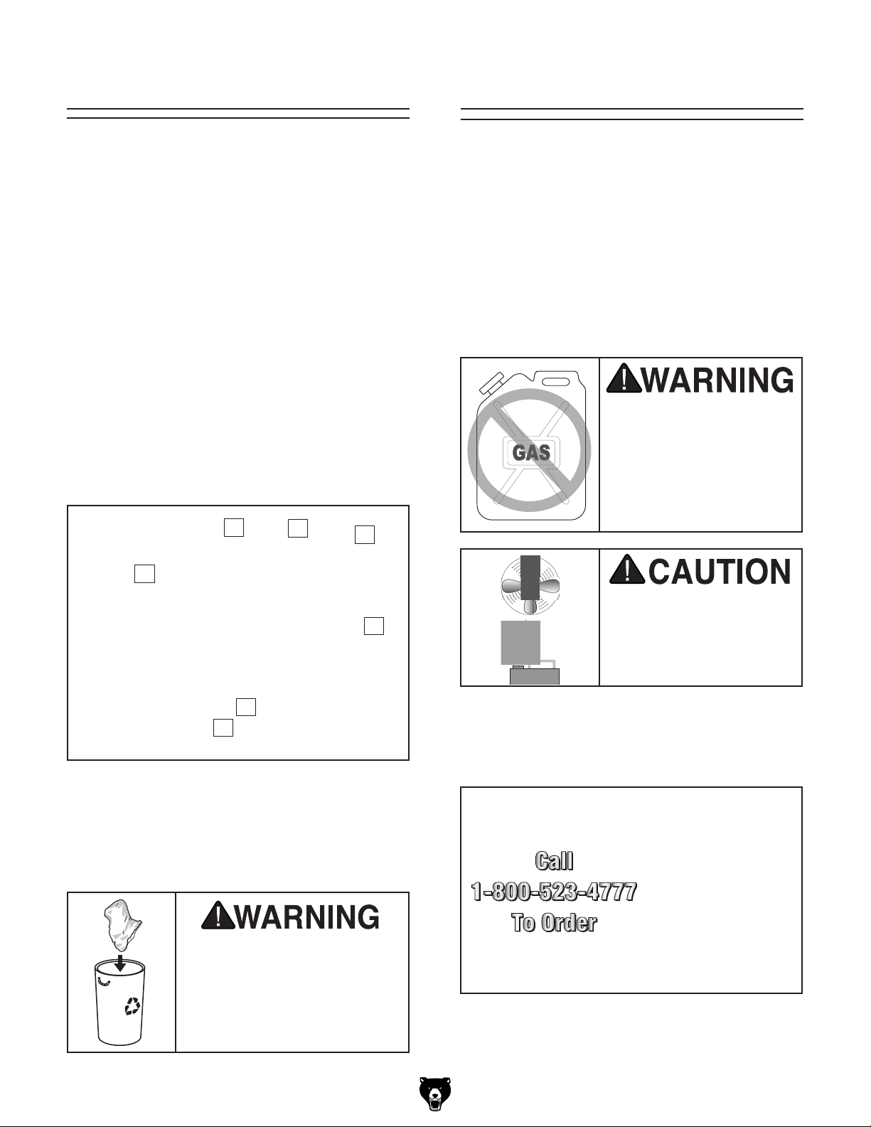
The unpainted surfaces are coated with a waxy
oil to prevent corrosion during shipment. Remove
this protective coating with a solvent cleaner or
degreaser, such as shown in Figure 4. For thorough cleaning, some parts must be removed.
For optimum performance, clean all moving
parts or sliding contact surfaces. Avoid chlo-
rine-based solvents, such as acetone or brake
parts cleaner that may damage painted surfaces. Always follow the manufacturer’s instructions
when using any type of cleaning product.
Gasoline and petroleum
products have low flash
points and can explode
or cause fire if used to
clean machinery. DO
NOT use these products
to clean the machinery.
B
F
G
H
Figure 3. G0675 inventory.
If any nonproprietary parts are missing (e.g. a
nut or a washer), we will gladly replace them; or
for the sake of expediency, replacements can be
obtained at your local hardware store.
SUFFOCATION HAZARD!
Immediately discard all plastic bags and packing materials to eliminate choking/suffocation hazards for children
and animals.
Many cleaning solvents
are toxic if inhaled.
Minimize your risk by only
using these products in a
well ventilated area.
G2544—Solvent Cleaner & Degreaser
H9692—Orange Power Degreaser
Great products for removing shipping grease.
Figure 4. Cleaner/degreasers available from
Grizzly.
-12-
G0675 10" Jointer/Planer Combo Machine
Page 15
Site Considerations
Floor Load
Refer to the Machine Data Sheet for the weight
and footprint specifications of your machine.
Some residential floors may require additional
reinforcement to support both the machine and
operator.
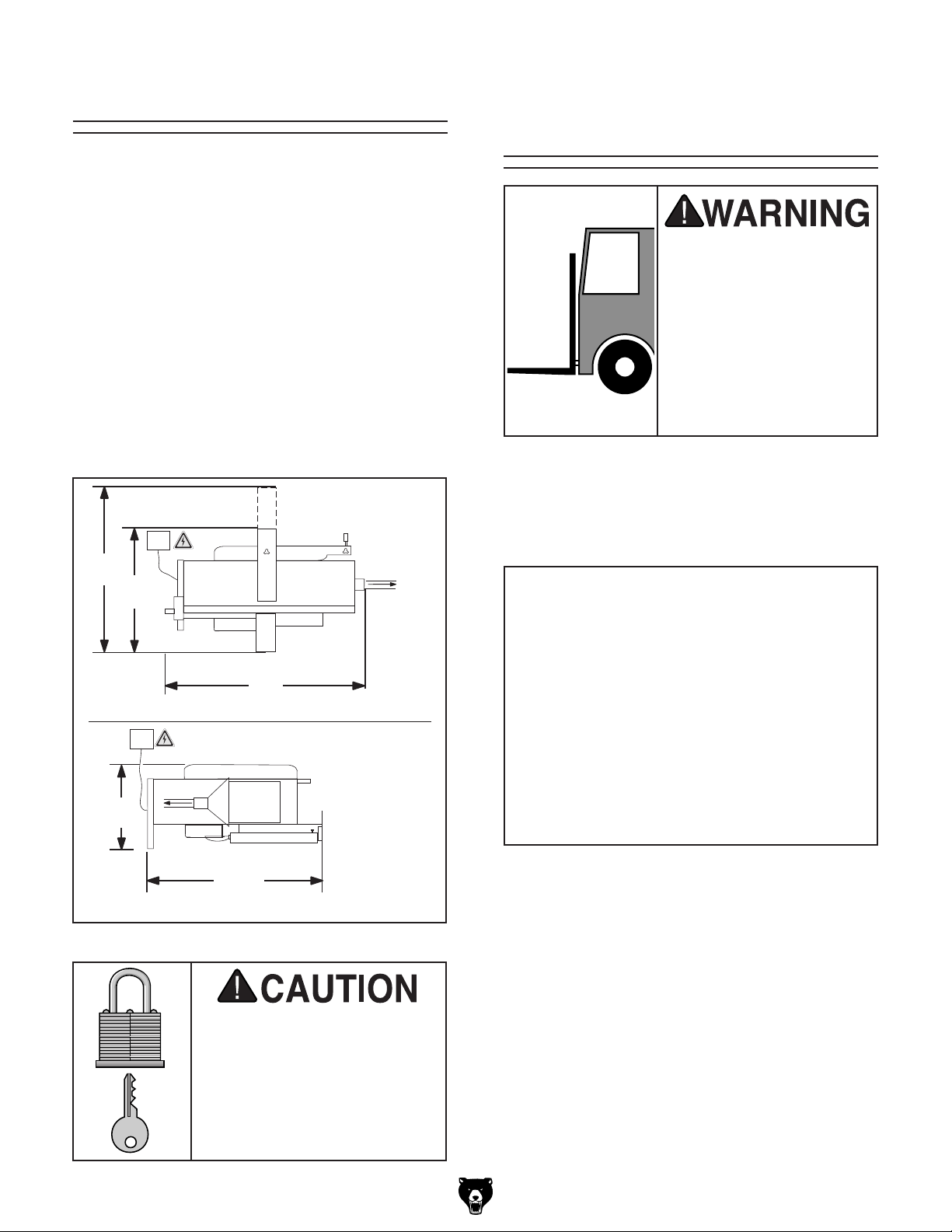
Placement Location
Consider existing and anticipated needs, size of
material to be processed through each machine,
and space for auxiliary stands, work tables or
other machinery when establishing a location for
your new machine. See Figure 5 for the minimum
working clearances.
220V
40"
15A
4" Dust
Collection Port
27"
4" Dust
Collection Port
Moving & Placing
Base Unit
The Model G0675 is a
heavy machine. Serious
personal injury may occur
if safe moving methods
are not used. To be safe,
get assistance and use
power equipment to move
the shipping crate and
remove the machine from
the crate.
Use a forklift to lift the jointer/planer just enough
to clear the shipping pallet and floor obstacles,
then move it to a suitable location, as shown in
Figure 6.
50"
Jointer Mode
220V
15A
20"
4" Dust
Collection Port
43½"
Planer Mode
Figure 5. Minimum working clearances.
Children and visitors may be
seriously injured if unsupervised around this machine.
Lock entrances to the shop
or disable start switch or
power connection to prevent
unsupervised use.
G0675 10" Jointer/Planer Combo Machine
Figure 6. Lifting model G0675 with a forklift.
If you are unsure how to lift this machine, consult
a qualified professional.
Place a level on the table and level the machine
front-to-back and side-to-side by adjusting the
height of the feet. Raise or lower each rubber
foot by turning the hex nut above each foot with a
16mm wrench, then tighten the top locking nut.
If you have trouble adjusting the feet, unlatch the
top from the base and, with the help of an assistant, set it aside. Adjust the feet, level the base,
secure the hex nuts, then reinstall the top with the
assistant's help.
-13-
Page 16
Mounting to Shop
Floor
Although not required, we recommend that you
mount your new machine to the floor. Because
this is an optional step and floor materials may
vary, floor mounting hardware is not included.
Bolting to Concrete Floors
Lag shield anchors with lag bolts (Figure 9) and
anchor studs are two popular methods for anchoring an object to a concrete floor. We suggest
you research the many options and methods for
mounting your machine and choose the best that
fits your specific application.
To mount the base to the floor:
1. Unlatch the machine top from the base at
both ends (Figure 7).
Figure 7. Location of latches.
2. With the help of an assistant set the machine
top aside.
3. Remove the rubber feet and install 10mm or
3
⁄8" bolts through the mounting holes (Figure
8) .
NOTICE
Anchor studs are stronger and more permanent alternatives to lag shield anchors;
however, they will stick out of the floor,
which may cause a tripping hazard if you
decide to move your machine.
Anchor Stud
Lag Bolt & Lag Shield Anchor
Figure 9. Typical fasteners for mounting to
concrete floors.
Figure 8. Base mounting holes.
4. Level the base with a precision level and
shims, as needed.
5. Set the machine top back on the base and
secure the latches.
-14-
G0675 10" Jointer/Planer Combo Machine
Page 17
Assembly
Tip: Try tightening one cap screw several turns,
then repeat with other until both are tight.
This section covers how to setup your machine
for jointing operations. Once you have completed
the assembly and Test R un (Page 18), you can
convert the machine for planer operation (refer to
Page 22).
To assemble the machine:
1. Pull up on the fence lock lever, then place the
fence assembly onto the table fence rail, as
shown in Figure 10.
Fence Rail
Handle
Bracket
Lock
Lever
Figure 10. Fence installed.
2. Engage the blade guard lever, align the cap
screws on the arm with the mounting holes
on the outfeed table, then tighten the screws
(see detail in Figure 11).
3. Loosen the guard lock knob, slide the blade
guard into the bracket, then tighten the lock
knob (see Figure 12).
Guard Lock
Knob
Blade Guard
Bracket
Figure 12. Blade guard installed.
To raise the blade guard, turn the height
adjustment knob counterclockwise (Figure
11); to lower the blade guard, turn the knob
clockwise.
4. Loosen the thumb screw on the dust hood
assembly, insert the dust port into the dust
hood assembly, then tighten the thumb screw
(see Figure 13). Make sure the fingers on the
dust hood slide all the way into the grooves
on the port.
Guard
Lever
Height
Knob
Figure 11. Blade guard arm installed.
G0675 10" Jointer/Planer Combo Machine
Guard
Arm
Dust Port
Figure 13. Installing dust port.
Thumb
Screw
Dust Hood
Assembly
-15-
Page 18

Dust Collection
DO NOT operate the Model G0675 without an adequate dust collection system.
This machine creates substantial amounts
of wood dust while operating. Failure to use
a dust collection system can result in longterm respiratory illness.
Recommended CFM at Dust Port: 400 CFM
Do not confuse this CFM recommendation with
the rating of the dust collector. To determine the
CFM at the dust port, you must consider these
variables: (1) CFM rating of the dust collector,
(2) hose type and length between the dust collector and the machine, (3) number of branches
or wyes, and (4) amount of other open lines
throughout the system. Explaining how to calculate these variables is beyond the scope of
this manual. Consult an expert or purchase a
good dust collection "how-to" book.
To connect a dust collection hose:
1. Fit the 4" dust hose over the dust port when
it is correctly positioned for jointer operation
(Figure 14) or planer operation (Figure 15),
and secure in place with a hose clamp.
Figure 15. Dust hose attached to dust port setup
for planer operations.
Refer to the instructions on Page 22 (Planer
Operations Setup) for setting up the dust
chute for planer operations.
2. Tug the hose to make sure it does not come
off.
Note: A tight fit is necessary for proper per-
formance.
Figure 14. Dust hose attached to dust port set-
up for jointer operations.
-16 -
G0675 10" Jointer/Planer Combo Machine
Page 19
Setting Outfeed
Table Height
The outfeed table height MUST be level with the
knives when they are at top-dead-center. If the
outfeed table is set too low, the workpiece will be
tapered. If the outfeed table is set too high, the
workpiece will hit the edge of the outfeed table
during operation, increasing the chance of kickback.
To set the outfeed table height:
1. DISCONNECT THE JOINTER/PLANER
FROM THE POWER SOURCE!
2. Move the blade guard out of the way or
remove it.
3. Secure the outfeed table with the outfeed
table lock.
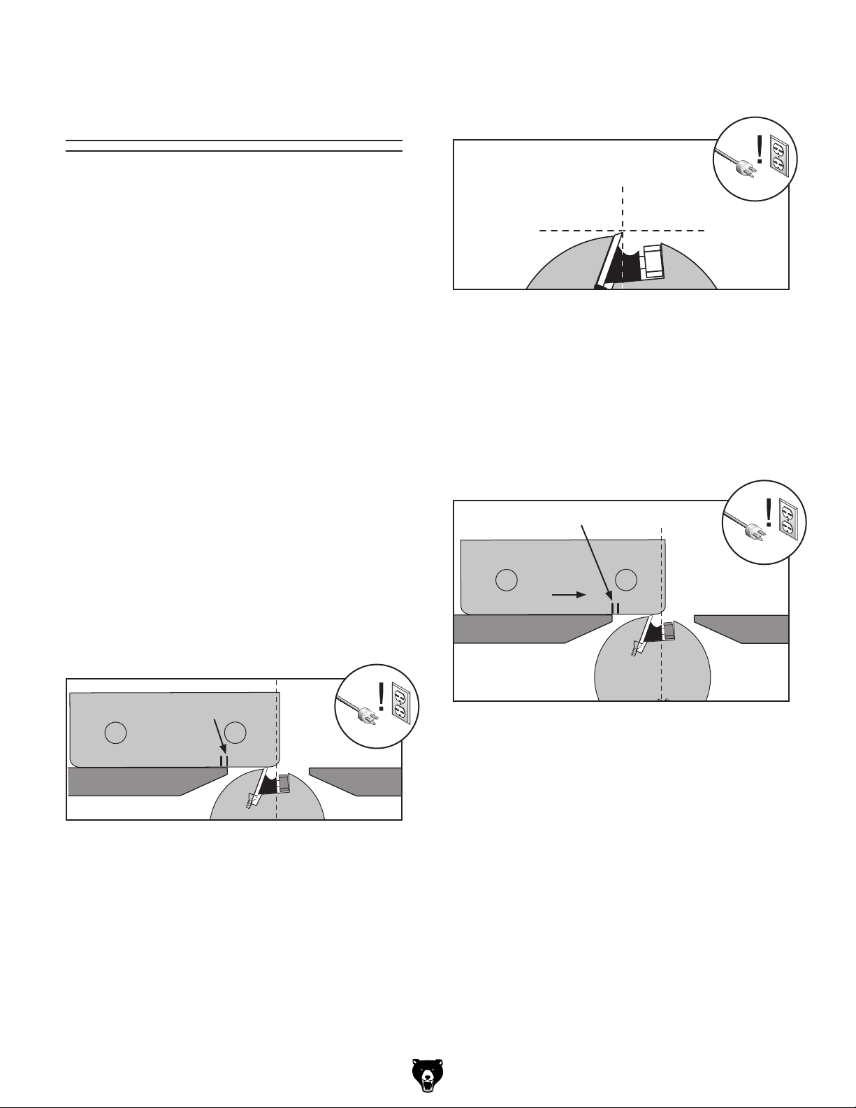
6. Rotate the cutterhead pulley until one of the
knives is at top dead center (TDC), as shown
in Figure 17.
Top Dead
Center
Figure 17. Cutterhead knife at top-dead-center.
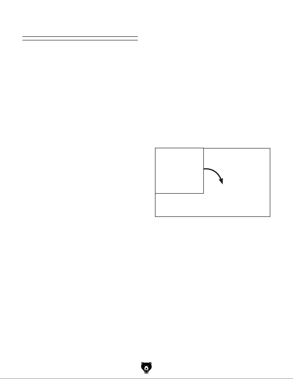
7. When the outfeed table is correctly set, the
knife will just touch the gauge when the knife
is at its highest point of rotation (Figure 18).
When the cutterhead pulley is rotated, the
gauge should move
table and the inward mark should be directly
over the edge of the outfeed table (Figure
18).
1
⁄8" toward the infeed
4. Remove the front access panel (see
Replacing Flat Drive Belt, Steps 3-4 on
Page 33) to access the cutterhead pulley.
5. Place the knife setting gauge on the front of
the outfeed table so the gauge extends over
the cutterhead and the outward mark is at the
edge of the outfeed table (Figure 16).
Outward Mark
Outfeed
Figure 16. Knife gauge positioned over
cutterhead knife.
Infeed
Inward Mark
1
⁄8"
Outfeed
Figure 18. Knife gauge positioned over
cutterhead knife.
—If your outfeed table is correctly set, no
adjustments are necessary.
—If the knife lifts the gauge off the table or
the table is below the gauge, continue to
Checking Outfeed Table Parallelism on
Page 39 in the SERVICE section.
8. Reinstall the front access panel and blade
guard.
Infeed
G0675 10" Jointer/Planer Combo Machine
-17-
Page 20
Test Run
—If the cutterhead does not rotate, the
cutterhead safety switch is working correctly. Continue to Step 10.
Once the assembly is complete, test run your
machine to make sure it runs properly.
The test run consists of verifying the following: 1)
The motor powers up and runs correctly, and 2)
the cutterhead safety switch works correctly.
If, during the test run, you cannot easily locate
the source of an unusual noise or vibration, stop
using the machine immediately, then review the
Troubleshooting on Page 37.
If you still cannot remedy a problem, contact our
Tech Support at (570) 546-9663 for assistance.
To test run the machine:
1. Make sure you have read the safety instruc-
tions at the beginning of the manual and you
have performed the assembly instructions.
2. Make sure all tools and objects used during
setup are cleared away from the machine.
— If the cutterhead rotates, immediately stop
the machine and DISCONNECT THE
JOINTER/PLANER FROM THE POWER
SOURCE! The safety switch is not working correctly. This safety feature must work
properly before proceeding with regular
operations. Call Tech Support for help.
10. Set the machine up for planer operations.
Refer to Planer Operation Setup, Steps 1-5
on Page 22, for detailed instructions.
11. Swing the dust chute assembly clockwise
over the cutterhead and rest the catch lever
on the infeed table, as shown in Figure 19.
3. Push the outfeed table lock lever down.
4. Connect the machine to the power source.
5. Open the switch cover and press the green
ON button to turn the machine ON.
6. Listen to and watch for abnormal noises or
actions. The machine should run smoothly
with little or no vibration or rubbing noises.
— Investigate and correct strange or unusual
noises or vibrations before operating the
machine further. Always disconnect the
machine from power when investigating or
correcting potential problems.
7. Turn the machine OFF.
8. Move the fence all the way back and com-
pletely cover the cutterhead with the blade
guard.
9. Disengage the outfeed table lock lever, lift the
outfeed table up about an inch or until you
hear a "click" then turn the machine ON.
Figure 19. Dust chute catch disengaged.
12. Turn the machine ON.
—If the cutterhead does not rotate, the
cutterhead safety switch is working correctly. The test run is complete.
—If the cutterhead rotates, immediately stop
the machine and DISCONNECT THE
JOINTER/PLANER FROM THE POWER
SOURCE! The safety switch is not working correctly. This safety feature must work
properly before proceeding with regular
operations. Call Tech Support for help.
13. To finish setting up the machine for planer
operation, push the dust chute down until
you hear a "click," indicating the dust chute is
locked, then connect the dust hose.
14. To convert the machine to a jointer, follow the
Jointer Operation Setup on Page 23.
-18-
G0675 10" Jointer/Planer Combo Machine
Page 21

Recommended
Adjustments
For your convenience, the adjustments listed
below have been performed at the factory and
no further setup is required to operate your
machine.
However, because of the many variables involved
with shipping and storage, some of these adjustments may need to be repeated to ensure optimum cutting results. Keep this in mind as you
start to use your new jointer/planer.
Step-by-step instructions for these adjustments can be found in SECTION 7: SERVICE
ADJUSTMENTS.
Factory adjustments that should be verified:
1. Cutterhead Knife Height (Page 42)
Belt Break-In
The final step in the setup process must be done
after approximately three hours of operation.
During this first three hours, the belts will stretch
and seat into the pulley grooves. After this, you
must re-tension the belts to avoid slippage and
burn out. Refer to Page 32 when you are ready to
perform this important adjustment.
Note: Pulleys and belts can get hot. This is a normal condition. Allow them to cool before making
adjustments.
2. Fence Stop Accuracy (Page 44)
3. Feed Roller Spring Tension (Page 46)
4. Jointer-Table Parallelism (Page 39)
G0675 10" Jointer/Planer Combo Machine
-19 -
Page 22
SECTION 4: OPERATIONS
Basic Jointer
To reduce the risk of
serious injury when using
this machine, read and
understand this entire
manual before beginning
any operations.
Damage to your eyes, lungs, and ears could
result from using this machine without
proper protective gear. Always wear safety
glasses, a respirator, and hearing protection
when operating this machine.
Controls
This section covers the controls used during
routine jointer operations. To use the machine
as a planer, you must perform a conversion (see
Jointer-Planer Conversion on Page 22).
ON/OFF Button (Figure 20): Starts or stops
motor when pushed in.
On
Button
Loose hair, clothing, or
jewelry could get caught
in machinery and cause
serious personal injury.
Keep these items away
from moving parts at all
times to reduce this risk.
NOTICE
If you have never used this type of machine
or equipment before, WE STRONGLY RECOMMEND that you read books, trade magazines, or get formal training before beginning any projects. Regardless of the content in this section, Grizzly Industrial will
not be held liable for accidents caused by
lack of training.
Off Button
Figure 20. ON/OFF button locations.
Table Movement: Raise or lower the infeed table
adjustment lever (Figure 21) to control how much
stock is removed by the cutterhead.
Scale
Outfeed Table
Lock
Fence Lock
Infeed Table
Adjustment
Lever
-20-
Figure 21. Fence and table height controls.
G0675 10" Jointer/Planer Combo Machine
Page 23

To unlock the outfeed table, raise the outfeed
table lock lever. To lock the outfeed table, lower
the outfeed table, then engage the lock lever.
Fence Movement: The fence lock keeps the
fence in position (Figure 21). To move the fence,
loosen the fence lock, slide the fence to the
desired position, then secure the lock.
Fence Tilting: The tilt locks (Figure 22) secure
the fence at any position in the available range.
Fence stops set the fence at 90° or 45° outward.
The tilt locks must be tightened before cutting.
See Page 44 for more detail on setting the fence
stops.
Bevel
Figure 23. Fence bevel flush with table at 45°.
Fence Height
Knobs
Locks
Figure 22. Fence tilt controls.
To move the fence to 45° outward, loosen the tilt
locks and fence height knobs, move the blade
guard away from the fence several inches, and
move the fence bevel flush against the table (see
Figure 23). Verify the angle with a 45° square,
then tighten the height knobs and tilt locks.
To return the fence to the 90° position, loosen the
tilt locks and height knobs, raise the fence to 90°.
Check the fence angle with a 90° square, making
sure the fence and table are flush, then tighten the
height knobs and tilt locks.
Angle Scale
Tilt
Blade Guard: To position the blade guard over
the cutterhead (Figure 24), loosen the lock knob,
reposition the guard, then tighten the lock knob.
Place the guard as close as possible to the
cutterhead during operations to reduce the risk of
serious injury from cutterhead contact—while also
allowing adequate clearance for workpieces.
Lock Knob
Adjustment
Knob
Lock Lever
Figure 24. Blade guard controls.
Blade Guard Arm: To adjust the blade guard
height, turn the adjustment knob (see Figure 24)
clockwise to lower and counterclockwise to raise
the blade guard. To move the bracket and blade
guard out of the way, disengage the lock lever,
then rotate the bracket assembly away from the
outfeed table.
G0675 10" Jointer/Planer Combo Machine
-21-
Page 24

Basic Planer
Jointer-Planer
Controls
This section covers the controls used during routine planer operations.
See Page 20 for a description of the ON/OFF
switch.
Table Height Handwheel: To raise or lower the
planer table, rotate the table height handwheel
(Figure 25).
Table Height Scale: Read the depth-of-cut from
the inch scale.
Conversion
The Model G0675 is ready for jointer operations
after it is setup. To use the machine as a planer,
you must perform a conversion.
Planer Operation Setup
1. DISCONNECT THE JOINTER/PLANER
FROM THE POWER SOURCE!
2. Loosen the fence lock lever, then remove the
fence.
3. Engage the blade guard lock knob and blade
guard arm lock lever (see Figure 24 on Page
21).
4. Disengage the outfeed table lock lever, and
raise the table up all the way so the pin seats
into the groove on the lock arm (Figure 26).
Table Height
Scale
Table Height
Handwheel
Figure 25. Planer table control locations.
Figure 26. Outfeed table lock arm.
Serious personal injury could occur if you
place your fingers between the table and
base or between pivot points. Your hands
could be pinched or crushed!
5. Remove the dust hose from the jointer dust
port, then remove the dust port.
-22-
6. Use the table height handwheel to lower the
planer table to approximately the 6" mark.
G0675 10" Jointer/Planer Combo Machine
Page 25

7. Swing the dust chute assembly clockwise
over the cutterhead, then push it down onto
the infeed table until you hear a "click"—this
indicates that the lock lever (Figure 27) has
secured the infeed table. The lever must
engage the infeed table for the planer to
operate.
Dust Port
Thumb Knob
Lock
Lever
Figure 27. Dust chute secured.
Jointer Operation Setup
1. Reverse Steps 2–8 in the previous subsec-
tion. You must push the catch lever back to
release the dust port.
2. While holding the outfeed table up, push
the lock arm pin out to fold the lock arm in
and lower the outfeed table most of the way
(Figure 26). When the table is close to the
frame, raise the outfeed table lock lever,
lower the table the rest of the way, then push
the lever down to secure the outfeed table.
3. Re-install the fence.
The dust chute must be secured during
planer operations or the machine will not
operate. If the machine DOES operate when
the dust chute lock is disengaged, immediately DISCONNECT THE JOINTER/PLANER
FROM POWER and call Technical Support.
8. Install the dust port onto the dust chute with
the thumb knob, as shown in Figure 27, then
install the dust hose with a hose clamp.
G0675 10" Jointer/Planer Combo Machine
-23-
Page 26

With Grain
Against Grain
CORRECT
INCORRECT
Stock Inspection
and Requirements
CORRECT
Here are some rules to follow when choosing stock for the jointer/planer:
• DO NOT joint or surface plane stock that
contains knots. Injury to the operator or
damage to the workpiece can occur if the
knots become dislodged during the cutting
operation.
• DO NOT joint or surface plane against the
grain direction. Cutting against the grain
increases the likelihood of stock kickback, as
well as tear-out on the workpiece.
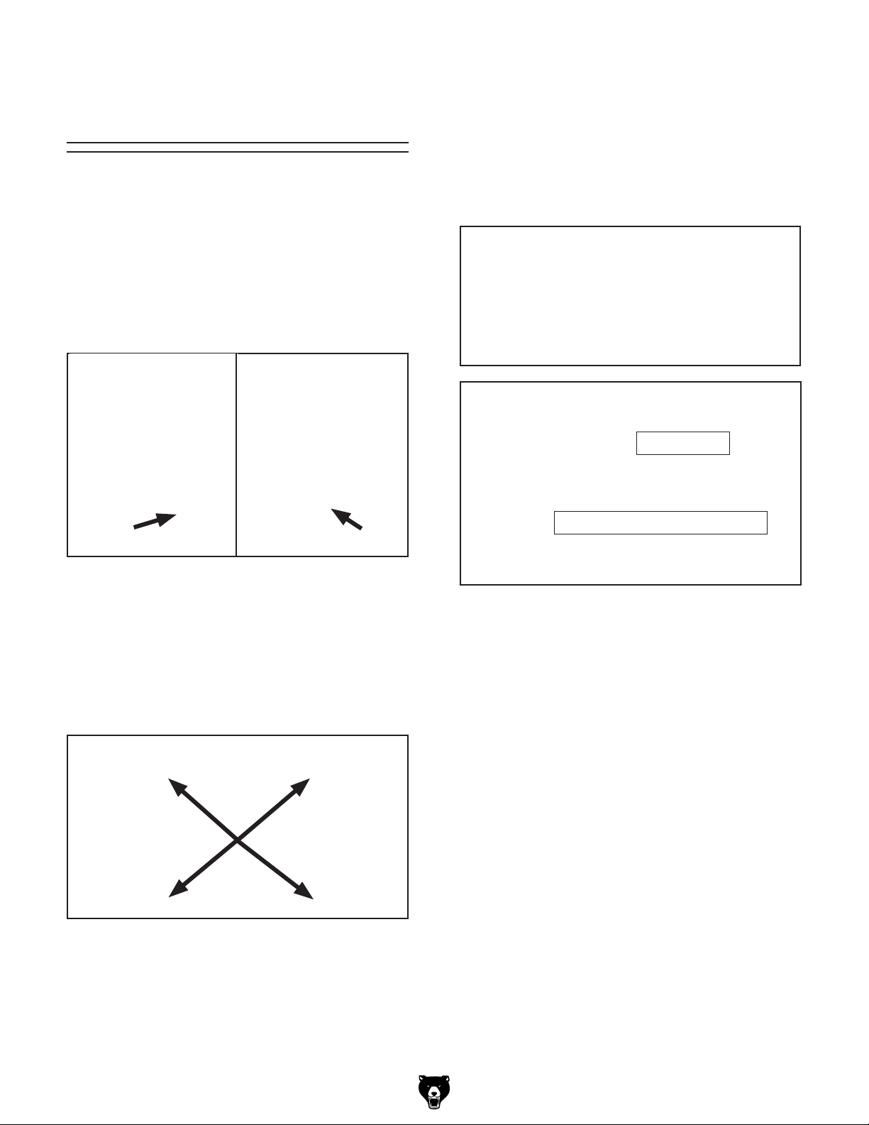
• Jointing and surface planing with the
grain produces a better finish and is safer
for the operator. Cutting with the grain is
described as feeding the stock so the grain
points down and toward you on the jointer
(Figure 28) or away from you on the planer
(Figure 29), as viewed from the edge.
Note: If the grain changes direction along the
edge of the board, decrease the cutting depth
and make additional passes.
With Grain
INCORRECT
Against Grain
Figure 29. Correct and incorrect grain alignment
to cutterhead (planer).
• Remove foreign objects from the stock.
Make sure that any stock you process with
the jointer/planer is clean and free of any dirt,
nails, staples, tiny rocks or any other foreign
objects, which if they hit the knives and are
drawn into the dust collector, may cause a
fire hazard. The particles may also damage
the knives. Wood stacked on a concrete floor
can have small pieces of stone or concrete
pressed into the surface.
• Only process natural wood fiber through
your jointer/planer. Never joint MDF, particle board, plywood, laminates or other synthetically made materials.
Figure 28. Correct and incorrect grain alignment
-24-
• Make sure all stock is sufficiently dried
before jointing or planing. Wood with a
moisture content over 20% will cause unnecessary wear on the knives and poor cutting
results. Excess moisture can also hasten rust
and corrosion.
• Scrape all glue off of boards before planing.
• Keep your work area clear.
to cutterhead (jointer).
G0675 10" Jointer/Planer Combo Machine
Page 27

15
30
45
Jointer Specific Rules:
• Make sure your workpiece exceeds
the minimum dimension requirements
(Figures 30 & 31) before edge jointing or
surface planing, or it may break or kick
back during the operation!
Squaring Stock
Squaring stock involves four steps performed
in the order below:
1. Surface Plane on the Jointer—The con-
cave face of the workpiece is surface planed
flat with a jointer.
1" Min.
12" Min.
1
⁄2" Min.
1
⁄2" Min.
12" Min.
1" Min.
Figure 30. Minimum dimensions for edge jointing
and surface planing (jointer).
Thickness Planer Specific Rules:
• Use the full width of the planer. Alternate
between the left, the right, and the middle
when feeding narrow lumber into the planer.
Your knives will remain sharp much longer.
12" Min.
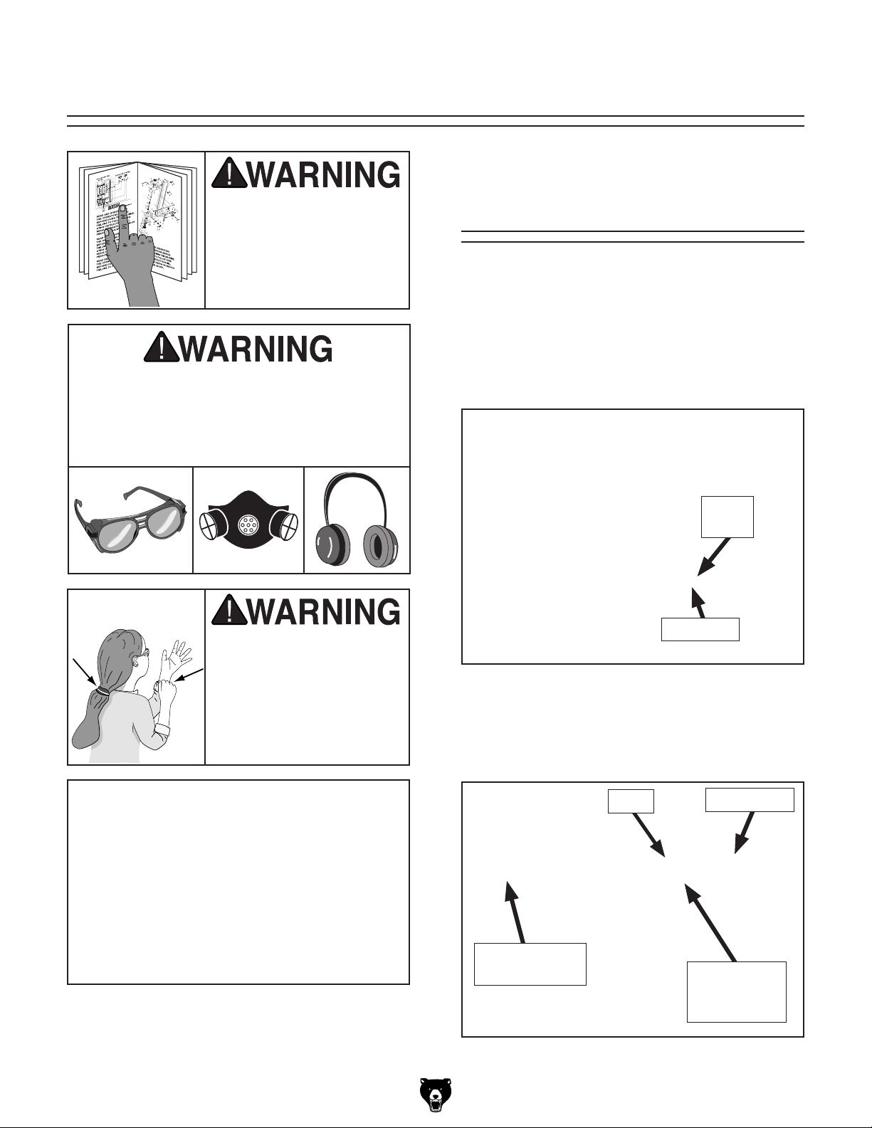
2. Surface Plane on the Thickness Planer—
The opposite face of the workpiece is surface
planed flat with a thickness planer.
Previously
Surface
Planed Face
3. Edge Joint on the Jointer—The concave
edge of the workpiece is jointed flat with a
jointer.
1
⁄4" Min.
1" Min.
Figure 31. Minimum dimensions for surface
planing (thickness planer).
G0675 10" Jointer/Planer Combo Machine
4. Rip Cut on a Table Saw—The jointed edge
of the workpiece is placed against a table
saw fence and the opposite edge cut off.
Previously
Jointed Edge
-25-
Page 28

Surface Planing
The purpose of surface planing on the jointer is
to make one flat face on a piece of stock (see
Figures 32 –34) to prepare it for thickness planing
on the planer.
NOTICE
If you are not experienced with a jointer,
set the depth of cut to 0", and practice
feeding the workpiece across the tables as
described. This procedure will better prepare you for the actual operation.
5. Adjust the blade guard for the workpiece
thickness.
— If the workpiece is less than or equal to 3"
thick, adjust the guard so it touches the
fence and is just above the workpiece—
allowing the workpiece to move freely (see
Figure 33). Tighten the blade guard lock
knob.
Figure 32. Illustration of surface planing results.
To surface plane on the jointer:
1. Read and understand SECTION 1: SAFETY,
beginning on Page 6.
2. Make sure your stock has been inspected
for dangerous conditions as described in the
Stock Inspection & Requirements instructions, beginning on Page 24.
3. Set the cutting depth for your operation. (We
suggest
shallow depth for hard wood species or for
wide stock.)
4. Make sure your fence is set to 90˚.
1
⁄32" for surface planing, using a more
Figure 33. Surface planing board less than 3"
thick.
— If the workpiece is greater than 3" thick,
adjust the blade guard
the workpiece (see Figure 34), lower the
guard to its lowest position (about
the cutterhead) then tighten the blade
guard lock knob.
3
⁄8"-1⁄2"
Figure 34. Surface planing stock greater than 3"
thick.
3
⁄8" to 1⁄2" away from
3
⁄4" over
-26-
G0675 10" Jointer/Planer Combo Machine
Page 29

Failure to use push blocks when surface
planing may result in cutterhead contact,
which will cause serious personal injury.
Always use push blocks to protect your
hands when surface planing on the jointer.
6. If your workpiece is cupped (warped), place
it so the concave side is face down on the
surface of the infeed table.
7. Start the jointer.
8. With a push block in each hand, press the
workpiece against the table and fence with
firm pressure, and feed the workpiece over
the cutterhead.
Note: If your leading hand (with push block)
gets within 4" of the cutterhead, lift it up and
over the cutterhead, and place the push
block on the portion of the workpiece that is
on the outfeed table. Now, focus your pressure on the outfeed end of the workpiece
while feeding, and repeat the same action
with your trailing hand when it gets within 4"
of the cutterhead. To keep your hands safe,
DO NOT let them get closer than 4" from the
cutterhead when it is moving!
9. Repeat Step 8 until the entire surface is flat.
G0675 10" Jointer/Planer Combo Machine
-27-
Page 30

Edge Jointing
The purpose of edge jointing is to produce a finished, flat-edged surface (see Figures 35 & 36)
that is suitable for joinery or finishing. It is also a
necessary step when squaring rough or warped
stock.
To edge joint on the jointer:
1. Read and understand SECTION 1: SAFETY,
beginning on Page 6.
2. Make sure your stock has been inspected
for dangerous conditions as described in the
Stock Inspection & Requirements instructions, beginning on Page 24.
NOTICE
If you are not experienced with a jointer,
set the depth of cut to 0", and practice
feeding the workpiece across the tables as
described below. This procedure will better
prepare you for the actual operation.
3
⁄8"-1⁄2"
Figure 35. Edge jointing operation.
3. Set the cutting depth for your operation. (We
suggest between
ing, using a more shallow depth for hard
wood species or for wide stock.)
4. Make sure the fence is set to 90˚, adjust
the blade guard
workpiece (see Figure 35), then tighten the
blade guard lock knob.
5. If your workpiece is cupped (warped), place
it so the concave side is face down on the
surface of the infeed table.
6. Start the jointer.
7. Press the workpiece against the table and
fence with firm pressure. Use your trailing
hand to guide the workpiece through the cut,
and feed the workpiece over the cutterhead.
Note: If your leading hand gets within 4"
of the cutterhead, lift it up and over the
cutterhead, and place it on the portion of
the workpiece that is over the outfeed table.
Now, focus your pressure on the outfeed end
of the workpiece while feeding, and repeat
the same action with your trailing hand when
it gets within 4" of the cutterhead. To keep
your hands safe, DO NOT let them get closer
than 4" from the cutterhead when it is moving!
1
⁄16" and 1⁄8" for edge joint-
3
⁄8" to 1⁄2" away from the
Figure 36. Illustration of edge jointing results.
-28-
8. Repeat Step 7 until the entire edge is flat.
G0675 10" Jointer/Planer Combo Machine
Page 31

Bevel Cutting
The purpose of bevel cutting is to cut a specific
angle into the edge of a workpiece (see Figures
37 & 38).
The Model G0675 has preset fence stops at 45˚
outward and 90˚. If your situation requires a different angle, the preset fence stops can be easily
adjusted for your needs.
NOTICE
If you are not experienced with a jointer,
set the depth of cut to 0", and practice
feeding the workpiece across the tables as
described below. This procedure will better
prepare you for the actual operation.
3
⁄8"-1⁄2"
To bevel cut on the jointer:
1. Read and understand SECTION 1: SAFETY,
beginning on Page 6.
2. Make sure your stock has been inspected
for dangerous conditions as described in the
Stock Inspection & Requirements instructions, beginning on Page 24.
3. Set the cutting depth for your operation. (We
suggest between
ting, using a more shallow depth for hard
wood species or for wide stock.)
4. Make sure your fence is set to the angle of
your desired cut, adjust the blade guard
1
⁄2" away from the workpiece (see Figure
to
37), then tighten the blade guard lock knob.
5. If your workpiece is cupped (warped), place
it so the concave side is face down on the
surface of the infeed table.
1
⁄16" and 1⁄8" for bevel cut-
3
⁄8"
Figure 37. Bevel cutting operation.
6. Start the jointer.
7. With a push block in your leading hand, press
the workpiece against the table and fence
with firm pressure, and feed the workpiece
over the cutterhead.
Note: If your leading hand gets within 4"
of the cutterhead, lift it up and over the
cutterhead, and place the push block on
the portion of the workpiece that is on the
outfeed table. Now, focus your pressure on
the outfeed end of the workpiece while feeding, and repeat the same action with your
trailing hand when it gets within 4" of the
cutterhead. To keep your hands safe, DO
NOT let them get closer than 4" from the
cutterhead when it is moving!
8. Repeat Step 7 until the angled cut is satisfactory to your needs.
Figure 38. Illustration of bevel cutting results.
G0675 10" Jointer/Planer Combo Machine
-29-
Page 32

Thickness Planer
Operation
—If the cut is too heavy and bogs down the
planer, turn the planer OFF immediately,
allow it to come to a complete stop, remove
the workpiece, and repeat Steps 3–5.
The Model G0675 planer table moves approximately
Each graduated mark on the table height
handwheel represents 0.001" movement.
To use the planer:
1. Put on safety glasses.
2. Unless your workpiece is very flat, surface
3. Adjust the table height to slightly lower than
4. Start the planer.
1
⁄16" with one full turn of the handwheel.
plane the workpiece on the jointer until it is
flat—having the face flat will ensure that it
sits flat on the planer table during operation.
your workpiece height to ensure the first
cut is as light as possible (approximately
1
⁄32"–1⁄16") .
6. Support the workpiece as it leaves the outfeed
end of the planer to reduce snipe.
7. Measure your workpiece thickness and adjust
the table height as necessary to take a lighter
or heavier pass, depending on your needs.
For most wood types,
cutting depth.
Note: Any time you switch directions with the
table height handwheel, there will be a small
amount of backlash—so the first crank of the
handwheel after switching directions will be
slightly less than
you move the handwheel in the same direction during operation, backlash will not be a
factor.
1
⁄16" per pass is a good
1
⁄16". However, as long as
5. Place the flat side of the board down on the
table (on the left side, facing the front of the
machine), and feed the workpiece through
the planer—in the opposite direction as when
jointing (see Figure 39). Make sure not to
stand directly in front or behind the workpiece
to avoid kickback injury.
Figure 39. Planer operation.
-30-
G0675 10" Jointer/Planer Combo Machine
Page 33

ACCESSORIES
SECTION 5: ACCESSORIES
®
G5562—SLIPIT
G5563—SLIPIT
G2871—Boeshield
G2870—Boeshield
H3788—G96
H3789—G96
1 Qt. Gel
®
12 oz Spray
®
Gun Treatment 12 oz Spray
®
Gun Treatment 4.5 oz Spray
®
T-9 12 oz Spray
®
T-9 4 oz Spray
G9643—8" Precision Straightedge
G9644—12" Precision Straightedge
H2675—16" Precision Straightedge
Ideal for aligning your outfeed bed to the cutterhead
and calibrating your depth scale. These grade
00 heavy-duty stainless steel straightedges are
manufactured to DIN874 standards for professional results in set-up and inspection work.
Figure 40. Recommended products for protect-
ing unpainted cast iron/steel parts on machinery.
G1738 —Rotacator™ Precision Planer Tool
The Rotacator is a dial indicator on a magnetic
base and is designed for quickly and accurately
setting the critical tolerances needed when adjusting any planer, so that nasty surprises such as
non-parallel and chattered cuts can be eliminated.
A great setup tool for other machines! Accurate to
0.001". Indicator rotates 360˚.
Figure 42. Straightedges.
T20501—Face Shield Crown Protector 4"
T20502—Face Shield Crown Protector 7"
T20503—Face Shield Window
T20451—"Kirova" Clear Safety Glasses
T20452—"Kirova" Anti-Reflective Glasses
H7194—Bifocal Safety Glasses 1.5
H7195—Bifocal Safety Glasses 2.0
H7196—Bifocal Safety Glasses 2.5
T20502
T20452
T20503
Figure 41. Rotacator™ Precision Planer Tool.
G0675 10" Jointer/Planer Combo Machine
H7194
T20451
Figure 43. Our most popular eye protection.
-31-
Page 34

SECTION 6: MAINTENANCE
Always disconnect power
to the machine before
performing maintenance.
Failure to do this may
result in serious personal injury.
Schedule
For optimum performance from your machine, follow this maintenance schedule and refer to any
specific instructions given in this section.
First 3–5 Hours of Operation
• Re-tension belts.
• Lubricate elevation lead screws (Page 35).
Daily Check:
• Clean unpainted cast iron parts of jointer and
planer tables.
• Clean cutterhead.
Every 20 Hours of Operation
• Lubricate elevation lead screws (Page 35).
Every 40 Hours of Operation
• Check and re-tension belts (on this page).
• Lubricate cogwheels (Page 35).
Monthly Check:
• Lubricate feed roller chain and feed roller
sprockets (Page 35).
• Lubricate fence (Page 34).
• Lubricate outfeed table lock arm and pivot
points (Page 36).
• Clean/vacuum dust inside planer cabinet.
• Lubricate blade guard arm (Page 35).
Semi-Anually
• Lubricate table height chain and planer
handwheel linkage (Page 36).
Note: This maintenance schedule is based on
average usage. Adjust the maintenance schedule
to match your usage to keep your jointer/planer
running smoothly and to protect your investment.
Cleaning
Vacuum excess wood chips and sawdust, and
wipe off the remaining dust with a dry cloth—this
ensures moisture from wood dust does not remain
on bare metal surfaces. Treat all unpainted cast
iron and steel with a non-staining lubricant after
cleaning. We recommend products like SLIPIT
®
Gun Treatment, or Boeshield® T-9 (see
G96
Page 31 for more details).
®
,
Belts
V-belt and flat belt removal and replacement
involves removing the belts, rolling them off of
the pulleys, replacing them with new belts, then
re-tensioning them.
Always replace the belts simultaneously, or belt
tension may not be even among the belts and
may cause premature belt failure.
After the first three hours of operation, re-tension
the belts, as they will stretch and seat during this
time. Then check and re-tension if necessary
after 40 operating hours.
Tools Needed Qty
Wrenches 10 & 13mm ..................................1 Ea
Hex Wrenches 5 & 6mm ..............................1 Ea
Replacing Flat Drive Belt
1. DISCONNECT THE JOINTER/PLANER
FROM THE POWER SOURCE!
Annually
• Lubricate table height chain and planer
handwheel (Page 36).
-32-
2. Raise the planer table to about the 6" mark.
G0675 10" Jointer/Planer Combo Machine
Page 35

3. Remove the four cap screws (Figure 44)
inside the cabinet on the fence side, then
remove the rear access panel.
6. Squeeze the flat belt in the middle to remove
tension, then tighten the locking nut nearby to
hold the drive pulley.
7. Remove the flat belt and install the new flat
drive belt onto the pulleys.
8. Loosen the locking nut to lower the drive pul-
ley.
Cap Screws
Front View
Rear View
Figure 44. Location of rear access panel screws.
4. Repeat Step 3 to remove the front access
panel.
5. Loosen the locking nuts on both sides of the
machine, as shown in Figures 45 & 46.
Flat Drive Belt
Motor
Pulley
9. Tighten both locking nuts and push the flat
belt in the center to check belt tension.
The belt is correctly tensioned when there
1
is approximately
⁄2" deflection when the flat
drive belt is pushed with moderate pressure, as shown in Figure 47. Continue to
Adjusting /Replacing Feed Cylinder Belts.
Pulley
1
⁄2 "
Deflection
Pulley
Locking Nut
Figure 45. Location of locking nut on rear of
machine.
Locking Nut
Figure 46. Location of locking nut on front of
machine.
G0675 10" Jointer/Planer Combo Machine
Figure 47. Checking belt tension.
— If there is more than 1⁄2" deflection when the
flat belt is pushed with moderate pressure,
loosen the locking nuts, adjust the motor
pulley downward, then tighten the locking
nuts. Continue to Adjusting/Replacing
Feed Cylinder Belts.
Adjusting/Replacing Feed Belts
1. DISCONNECT THE JOINTER/PLANER
FROM THE POWER SOURCE!
2. Raise the planer table to the 3" mark, remove
the four cap screws that secure the front
access panel, then remove the panel.
-33-
Page 36

3. Loosen the four cap screws on the wheel
bracket, and one cap screw on the infeed belt
wheel (see Figure 48), then raise the infeed
belt wheel.
Wheel Bracket
Flat Belt
Figure 48. Cap screw locations.
4. Remove the flat belt and V-belt, install a new
flat belt and V-belt in the same manner that
you removed them.
5. Push the wheel bracket (see Figure 48)
down and tighten the four cap screws, then
push the infeed belt wheel down and tighten
the cap screw loosened in Step 3.
Infeed
Belt
Wheel
V-belt
Lubrication
An essential step for lubrication is cleaning the
components before lubricating them.
This idea is critical because dust and chips build
up on lubricated components and make the
components hard to move. Simply adding more
grease to the components with built-up grime on
them will not yield smooth moving components.
Clean the components in this section with an oil/
grease soluble cleaner, such as mineral spirits.
The following are the main components that need
to be lubricated:
• Fence (on this page)
• Blade Guard Arm (Page 35)
• Leadscrews (Page 35)
• Feed Roller Chain, Sprocket and Cogwheels
(Page 35)
• Outfeed Table (Page 36)
• Table Height Chain (Page 36)
• Planer Table Handwheel (Page 36)
Schedules are based on average use. Adjust
lubrication according to your level of use.
6. Check the tension of each belt.
1
— If there is approximately
when the flat belt or V-belt is pushed with
moderate pressure, the belts are correctly
tensioned.
1
— If there is more than
flat belt or V-belt is pushed with moderate
pressure, repeat Steps 3–5, then check
the tension again.
7. Re-install the front and rear access panels
with the cap screws you removed earlier.
⁄2" deflection when the
⁄2" deflection
Fence
Clean away any built up grime and debris with
a rag and mineral spirits, then place 1-2 drops
of light machine oil on the pivot points shown in
Figure 49 once a month. Move the fence through
its full range of motion to distribute the oil.
Figure 49. Fence lubrication locations.
-34-
G0675 10" Jointer/Planer Combo Machine
Page 37

Blade Guard Arm
Clean away any built up grime and debris with a
rag and mineral spirits, then place 1-2 drops of
light machine oil on the points shown in Figure
50 once a month.
Figure 50. Blade guard arm lubrication locations.
Leadscrews
Clean away debris and built-up grime on the leadscrews with a rag and mineral spirits, then apply a
thin coat of SAE 10-30W oil with a clean rag to the
four leadscrews in the locations shown in Figures
51–52 after the first five hours and then every 20
hours. Move the planer table through its full range
of motion to distribute the lubricant.
Figure 52. Additional leadscrew lubrication
locations.
Feed Roller Chain, Sprocket and
Cogwheels
Inspect the feed roller chain and feed roller
sprockets monthly. Thoroughly clean debris and
grime with a rag and mineral spirits, then use a
brush or rag to apply a thin coat of multi-purpose
grease when needed, as shown in Figure 53.
Remove the front panel to access.
Lubricate the cogwheels with a thin coat of multipurpose grease every 40 operating hours.
Feed
Roller
Chain
Sprocket
Photo Note: Show both sides like figure below.
Figure 51. Leadscrew-planer table lubrication
locations.
G0675 10" Jointer/Planer Combo Machine
Cogwheels
Figure 53. Feed roller chain, sprocket, and
cogwheel lubrication locations.
-35-
Page 38

Outfeed Table
Clean debris and grime from the outfeed table
lock arm and pivot points, then apply 1-2 drops
of light machine oil to the components shown in
Figure 54 once a month.
Figure 54. Outfeed table lubrication points.
To access the table height chain and planer table
handwheel linkage, remove the fence, front and
rear access panels, blade guard arm assembly,
and rear fence rail. With the help of an assistant, lift the machine off the base, then turn the
machine over and place it upside down on blocks,
carpet, or cardboard (see Figure 56).
Table Height Chain & Planer
Handwheel
Inspect the table height chain (see Figure 55)
every six months to a year. Clean away debris and
built-up grime on the chain with a rag and mineral
spirits, then apply a thin coat of multi-purpose
grease. Lubricate the planer table handwheel linkage with light machine oil as needed.
Table Height
Chain
Handwheel
Linkage
Figure 56. Machine turned over for access to
table height chain.
After lubricating the chain and handwheel mechanism, make sure the outfeed table is locked, then
reverse the prior steps to reassemble the jointer/
planer.
Figure 55. Table height chain and handwheel
linkage.
-36-
G0675 10" Jointer/Planer Combo Machine
Page 39

SECTION 7: SERVICE
Review the troubleshooting and procedures in this section to fix or adjust your machine if a problem develops. If you need replacement parts or you are unsure of your repair skills, then feel free to call our Technical
Support at (570) 546-9663.
Troubleshooting
Symptom Possible Cause Possible Solution
Machine does not
start or a breaker
trips.
Machine stalls or is
underpowered.
Machine has
vibration or noisy
operation.
1. Blown fuse.
2. Power supply switched OFF or at fault.
3. Plug/receptacle at fault/wired wrong.
4. Start capacitor at fault.
5. Wall circuit breaker tripped.
6. Wiring open/has high resistance.
7. Motor ON/OFF switch at fault.
8. Motor at fault.
9. Dust chute lock not engaged on infeed table
(planer operation); outfeed table unlocked
and raised up (jointer operation).
1. Feed rate/cutting speed too fast.
2. Workpiece material not suitable for
machine.
3. Machine undersized for task.
4. Belt(s) slipping.
5. Motor wired incorrectly.
6. Plug/receptacle at fault.
7. Pulley/sprocket slipping on shaft.
8. Motor bearings at fault.
9. Machine undersized for task.
10. Motor overheated.
11. Motor at fault.
1. Motor or component loose.
2. Knives/gibs at fault.
3. Blade at fault.
4. Belts worn or loose.
5. Pulley loose.
6. Motor mount loose/broken.
7. Machine incorrectly mounted.
8. Motor fan rubbing on fan cover.
9. Motor bearings at fault.
10. Cutterhead bearings at fault.
1. Replace fuse/ensure no shorts.
2. Ensure power supply is on/has correct voltage.
3. Test for good contacts; correct the wiring.
4. Test/replace if faulty.
5. Ensure circuit size is correct/replace weak breaker.
6. Check/fix broken, disconnected, or corroded wires.
7. Replace switch.
8. Test/repair/replace.
9. Engage the dust chute lock (planer); lock the outfeed
table down (jointer).
1. Decrease feed rate/cutting speed.
2. Only cut wood/ensure moisture is below 20%.
3. Use correct blade/reduce feed rate or depth of cut.
4. Tension/replace belt(s); ensure pulleys are aligned.
5. Wire motor correctly.
6. Test for good contacts/correct wiring.
7. Replace loose pulley/shaft.
8. Test/repair/replace.
9. Use sharp knives; reduce feed rate/depth of cut.
10. Clean motor, let cool, and reduce workload.
11. Test/repair/replace.
1. Inspect/replace damaged bolts/nuts, and re-tighten
with thread locking fluid.
2. Resharpen/replace knives; set knife alignment/
height correctly.
3. Replace warped/bent blade; resharpen dull blade.
4. Inspect/replace belts with a new matched set.
5. Realign/replace shaft, pulley, setscrew, and key.
6. Tighten/replace.
7. Tighten mounting bolts; relocate/shim machine.
8. Fix/replace fan cover; replace loose/damaged fan.
9. Test by rotating shaft; rotational grinding/loose shaft
requires bearing replacement.
10. Replace bearing(s)/realign cutterhead.
G0675 10" Jointer/Planer Combo Machine
-37-
Page 40

Symptom Possible Cause Possible Solution
Outfeed table does
not lock.
Outfeed table will
not close.
Excessive snipe
(gouge in the end
of the board that is
uneven with the rest
of the cut).
Workpiece stops/
slows in the middle
of the cut.
Workpiece feeds
erratically.
Chipping (consistent
pattern).
Fuzzy grain. 1. Wood may have high moisture content or
Long lines or ridges
that run along the
length of the board
Uneven knife marks,
wavy surface,
or chatter marks
across the face of
the board.
Glossy surface.
(Planer)
Chip Marks
(inconsistent
pattern). (Planer)
Board edge is
concave or convex
after jointing.
(Jointer)
1. Table lock lever engaged when table is
being closed.
1. Table lock arm stuck. 1. Push lock arm pin out; lubricate as needed.
1. Operator pushing down on trailing end of
workpiece.
2. Workpiece is not supported as it leaves the
planer.
1. Taking too heavy of a cut.
2. Pitch and glue build up on planer
components.
1. Rubber lining on rubber feed rollers has
eroded excessively.
1. Knots or conflicting grain direction in wood.
2. Nicked or chipped knife.
3. Taking too deep of a cut.
surface wetness.
2. Dull knives.
1. Nicked or chipped knives. 1. Replace knives (Page 43).
1. Knives not adjusted at even heights in the
cutterhead.
2. Worn cutterhead bearings.
1. Knives are dull.
2. Cutting depth too shallow.
1. Chips aren't being properly expelled from
the cutterhead.
1. Board not held with even pressure on infeed
and outfeed table during cut.
2. Board started too uneven.
3. Board has excessive bow or twist along its
length.
4. Insufficient number of passes.
1. Disengage table lock lever, lower table, then engage
lever.
1. Lift up on the trailing end of the workpiece as it
enters and leaves the planer.
2. Support the workpiece as it leaves the outfeed end
of the planer.
1. Take a lighter cut.
2. Clean the internal cutterhead components with a
pitch/resin dissolving solvent.
1. Replace feed rollers (Page 47).
1. Inspect workpiece for knots and grain direction; only
use clean stock.
2. Replace the knife (Page 43).
3. Take a smaller depth of cut. (Always reduce cutting
depth when surface planing or working with hard
woods.)
1. Check moisture content and allow to dry if moisture
is too high.
2. Replace the knives (Page 43).
1. Adjust the knives so they are set up evenly in the
cutterhead (Page 43).
2. Replace cutterhead bearings.
1. Replace the knives (Page 43).
2. Increase the depth of cut.
1. Use a dust collection system.
1. Hold board with even pressure as it moves over the
cutterhead.
2. Take partial cuts to remove the extreme high spots
before doing a full pass.
3. Surface plane one face so there is a good surface to
position against the fence.
4. It may take 3 to 5 passes to achieve a perfect edge,
depending on starting condition of board and depth
of cut.
-38-
G0675 10" Jointer/Planer Combo Machine
Page 41

Jointer Table
Parallelism
The tables of your jointer MUST be parallel with
the cutterhead and each other (see Figure 57) to
reduce the risk of workpiece kickback and to help
ensure good cutting results.
Tools Needed Qty
Straightedge ...................................................... 1
Hex Wrench 5mm ............................................. 1
Wrench 13mm ................................................... 1
Feeler Gauge Set .............................................. 1
Assistant ............................................................ 1
Checking Outfeed Table Parallelism
The outfeed table is preset by the factory parallel
with the cutterhead. However, it is critical to check
this setting.
To check outfeed table parallelism:
1. DISCONNECT THE JOINTER/PLANER
FROM THE POWER SOURCE!
2. Remove the blade guard arm assembly.
Black Lines Represent
Straightedge Positions
From Overhead View
Figure 57. Illustration of table parallelism
concept.
Adjusting the tables parallel with each other is
a complex and precise task that may take more
than an hour to complete.
Due to the complex nature of this task, we recommend that you double check the current table
positions to make sure that they really need to be
adjusted before starting.
Note: Typically, a tolerance of ± 0.005" in parallelism between the tables is considered acceptable.
When adjusting table parallelism, you must do
the following: 1) properly adjust the outfeed
table height and parallelism in relation to the
cutterhead, and 2) adjust the infeed table parallel
to the outfeed table, and 3) adjust the knives to
bring the outfeed table surface and cutting edges
of the knives to the same height.
3. Place the straightedge on the back of the
outfeed table so it hangs over the cutterhead
as shown in Figure 58.
Black Lines Represent
Straightedge Positions
From Overhead View
Back
Front
Figure 58. Straightedge positions for verifying if
the outfeed table is parallel with the cutterhead.
4. Try to fit a 0.060" feeler gauge (or combina-
tion of feeler gauges) between the cutterhead
body and the bottom of the straightedge
(Figure 59).
Note: Rotate the cutterhead to make sure the
knives do not interfere with proper measurement.
G0675 10" Jointer/Planer Combo Machine
-39-
Page 42

Note: The back side of the outfeed table is
factory set approximately 0.060" from the
cutterhead. The back side of the outfeed
table is not adjustable, so any adjustments to
parallelism must be made on the front of the
outfeed table.
Correcting Outfeed Table to
Cutterhead Parallelism
This procedure involves loosening the outfeed
table support blocks and adjusting their height to
raise or lower the front of the outfeed table until it
is parallel with the cutterhead.
To correct outfeed table parallelism:
0.060"
Straightedge
Outfeed Table
Feeler Gauge
Figure 59. Using feeler gauge to check outfeed
table-cutterhead height.
5. Place the straightedge on the front side of the
outfeed table so it hangs over the cutterhead,
as shown in Figure 59, then try to fit a
feeler gauge or combination of feeler gauges
between the cutterhead and bottom of the
straightedge.
—If the feeler gauge slides with slight resis-
tance between the ruler and cutterhead
and no gaps appear between the straightedge and the table, then the outfeed table
is already parallel with the cutterhead. Go
to Checking Infeed Table Parallelism on
Page 41.
—If the feeler gauge does not fit between the
ruler and cutterhead, or if there is a gap
between the straightedge and the table,
the outfeed table is not parallel with the
cutterhead. Correct the outfeed table parallelism, then correct the infeed table parallelism. Continue to Correcting Outfeed
Table to Cutterhead Parallelism.
1. Loosen the cap screws on both outfeed table
support blocks (see Figure 60).
Support Blocks
Cap Screw
Figure 60. Location of front outfeed table
support blocks.
2. Fit the 0.060" feeler gauge (or combination
of feeler gauges) onto the front side of the
cutterhead, then place the straightedge on
the front of the outfeed table and over the
feeler gauge.
3. While an assistant holds the feeler gauge and
straightedge, adjust the height of each support block until no gaps appear between the
straightedge and the table.
4. Tighten the cap screws on the suport blocks
to secure the adjustment.
5. Using the straightedge and the 0.060" feeler
gauge, verify again that no gaps appear
between the table and the straightedge.
-40-
6. Repeat Steps 1 –5 until the front outfeed table
parallelism is correct, then repeat Checking
Outfeed Table Parallelism on Page 39 to
ensure the outfeed table height above the
cutterhead is equal across the table.
7. Continue to Checking Infeed Table
Parallelism on Page 41.
G0675 10" Jointer/Planer Combo Machine
Page 43

Checking Infeed Table Parallelism
1. Follow all the steps for checking the outfeed
table parallelism to first make sure that the
outfeed table is parallel with the cutterhead.
—If the straightedge sits flat against both
the infeed and outfeed table, then the
tables are parallel. Continue to Inspecting
Knives on Page 42.
2. Place the straightedge halfway across the
infeed table and halfway over the outfeed
table, and adjust the infeed table even with
the outfeed table, as shown in Figure 61.
Straightedge
Outfeed Table Infeed Table
Figure 61. Infeed and outfeed tables set evenly.
—If a knife touches the straightedge, turn the
cutterhead so the knives do not interfere.
3. Place the straightedge in the positions shown
in Figure 62. In each position, the straightedge should sit flat against both the outfeed
table and the infeed table—you should not
see any gaps between the bottom of the
straightedge and the infeed table.
Black Lines Represent
Straightedge Positions
from Overhead View
—If the straightedge does not sit flat against
both the infeed and outfeed table in
any of the positions, then continue to
the Adjusting Infeed Table Parallelism
instructions.
Adjusting Infeed Table Parallelism
1. Perform the "Checking/Adjusting Table
Parallelism" procedure on Page 39, including
making any necessary adjustments so the
cutterhead and outfeed table are parallel.
2. Place the straightedge halfway across the
infeed table and halfway over the outfeed
table, and adjust the infeed table even with
the outfeed table, as shown in Figure 61.
3. Place the straightedge in one of the positions
shown in Figure 62.
—If the front of the infeed table is higher or
lower than the outfeed table, or if the rear
of the infeed table is higher or lower than
the outfeed table, continue to Step 4.
—If the straightedge sits flat against both
the infeed and outfeed table, then the
tables are parallel. Continue to Inspecting
Knives on Page 42.
Figure 62. Straightedge positions for checking
infeed/outfeed table parallelism.
G0675 10" Jointer/Planer Combo Machine
-41-
Page 44

4. Loosen the eight hex bolts and flange nuts
on both sides of the infeed table, as shown in
Figures 63 and 64.
Inspecting Knives
Tools Needed: Qty
Knife Setting Gauge .......................................... 1
Straightedge ...................................................... 1
The height of the knives can be inspected with the
included knife setting gauge.
Inspecting the height of the knives ensures that
they are set evenly with the outfeed table at their
highest point in the cutterhead rotation.
Figure 63. Location of infeed table adjustment
bolts, front view.
Figure 64. Locations of the infeed table
adjustment bolts.
5. While an assistant holds the straightedge
over both tables, lift or lower the infeed table,
then tighten the hex bolts and nuts as needed
so there is little to no visible gap between the
bottom of the straightedge and the top of the
infeed table.
To inspect the knives with the knife setting
gauge:
1. DISCONNECT THE JOINTER/PLANER
FROM THE POWER SOURCE!
2. Perform Steps 2–7 in Setting Outfeed Table
Height on Page 17.
— If the top of the knife just touches the bottom
of the gauge when it is at the highest point
of rotation on both sides of the cutterhead,
then that knife is set correctly. (Repeat this
inspection with the other knife.)
— If the top of the knife does not touch the
bottom of the gauge as described, then
reset that knife. Continue to Adjusting/
Replacing Knives on Page 43 (Repeat
this inspection with the other knife before
resetting.)
3. REPLACE the front access panel and the
blade guard assembly!
6. Continue adjusting the infeed table until it
is parallel with the outfeed table in each of
the positions shown in Figure 62. Some trial
and error and a good deal of patience will
be needed to successfully accomplish this
adjustment.
Tip: Tighten the front and rear bolts finger
tight and tap the table up or down. This will
help dial in the adjustment.
7. Once the infeed and outfeed tables are parallel with each other, proceed to Inspecting
Knives.
-42-
G0675 10" Jointer/Planer Combo Machine
Page 45

Adjusting/Replacing
Knives
Tools Needed: Qty
Straightedge ...................................................... 1
Hex Wrench 5mm .............................................. 1
Wrench 8 mm .................................................... 1
Setting the knives correctly is crucial to the proper
operation of the jointer/planer and is very important in keeping the knives sharp. If one knife is
higher than the others, it will do the majority of the
work, and thus, dull much faster than the others.
Knife Setting Gauge Method: The gauge is
placed on the outfeed table over the cutterhead,
as shown in Figure 65, and the knife heights
are set to just touch the gauge. The knife setting
gauge makes it easy to ensure that the knives
project out of the cutterhead evenly.
The Model G0675 comes with jack screws for
cutterhead adjustments (see Figure 66).
Knife
Gib Bolt
Figure 66. Cutterhead profile diagram.
To set or replace the knives:
1. DISCONNECT THE JOINTER/PLANER
FROM THE POWER SOURCE!
Gib
Loosen
Tighten
Jack
Screw
Outfeed
Figure 65. Using knife setting gauge to set knife
height.
Infeed
2. Remove the blade guard and fence from the
table.
3. Remove the rear access panel to expose the
cutterhead pulley.
4. Rotate the cutterhead pulley to give you good
access to one of the cutterhead knives.
5. Loosen the cutterhead gib bolts, starting in
the middle and alternating back-and-forth
until all of the gib bolts are loose but not falling out.
—If this is the first time you are setting the
knives, or if you are replacing them, remove
a gib and knife from the cutterhead. Clean
the gib and clean inside the cutterhead slot
to remove all pitch or sawdust. Coat the
knife and gib with a metal protectant (Page
31).
G0675 10" Jointer/Planer Combo Machine
-43-
Page 46

6. Edh^i^dc i]Z `c^[Z \Vj\Z dkZg i]Z `c^[Z Vh
h]dlc^cFigure 65VcYaddhZci]Z\^WWdaih
jci^ai]Z`c^[Z^hXdbeaZiZanaddhZ#
Setting Fence Stops
7. Jh^c\ V *bb ]Zm lgZcX]! gdiViZ i]Z _VX`
hXgZlh Figure 67 ^c i]Z VXXZhh ]daZh id
gV^hZdgadlZgi]Z`c^[Z#L]Zci]Z`c^[Z^hhZi
XdggZXian!^il^aaWVgZanidjX]i]ZWdiidbZY\Z
d[i]Z`c^[ZhZii^c\\Vj\ZdcWdi]h^YZhd[i]Z
XjiiZg]ZVYl]Zc^i^hgdiViZYWVX` VcY[dgi]#
Hcj\ i]Z\^W Wdaih i^\]i Zcdj\]id _jhi ]daY
i]Z`c^[Z^ceaVXZ#GZeZViSteps 5-7l^i]i]Z
gZbV^c^c\`c^[Z#
Figure 67.?VX`hXgZlVXXZhh]daZ#
I]Z[ZcXZhidehh^bea^[ni]ZiVh`d[VY_jhi^c\i]Z
[ZcXZid)*ßVcY.%ß#
Tools Needed Qty
)*HfjVgZ######################################################## &
.%HfjVgZ######################################################## &
Ha^Y^c\7ZkZa###################################################### &
=ZmLgZcX](bb############################################## &
=ZmLgZcX],bb############################################## &
GZ[ZgidFigures 69-70id^YZci^[ni]Z.%ßVcY)*ß
[ZcXZhideXdbedcZcih#
.%ß;ZcXZ
AdX`Cji
8. GdiViZ i]Z XjiiZg]ZVY id i]Z [^ghi `c^[Z ndj
VY_jhiZY# Ha^\]ian i^\]iZc Vaa i]Z \^W Wdaih!
hiVgi^c\Vii]Zb^YYaZVcYldg`^c\ndjglVnid
i]ZZcYhWnVaiZgcVi^c\aZ[iVcYg^\]iFigure
68#GZeZVii]^hhiZedci]ZgZbV^c^c\`c^[Z#
*
Figure 68.<^WWdaii^\]iZc^c\hZfjZcXZ#
9. GZeZVi Step 8! Wji [^cVa i^\]iZc ZVX] \^W
Wdai#
10. GZeaVXZi]ZgZVgVXXZhheVcZa!WaVYZ\jVgY!
VcY[ZcXZ#
(
&
'
)
)*ßHideHXgZl
Figure 69..%˚adX`cjiVcY)*ßhidehXgZl#
.%ßHide
HXgZl
6c\aZY7gVX`Zi
Figure 70#.%˚hidehXgZlVcY)*ßadX`cji#
)*ßAdX`
Cji
"))"
<%+,*&%?d^ciZg$EaVcZg8dbWdBVX]^cZ
Page 47

To set the 90˚ fence stop:
1. Loosen the 90˚ lock nut (Figure 69) and stop
screw (Figure 70), and loosen the fence tilt
locks.
2. Using a 90˚ square, adjust the fence to the
90˚ position, as shown in Figure 71.
3. Using a 45° square, adjust the fence to the
45° outward position (Figure 72).
Figure 72. Adjusting fence 45˚ outward.
4. Secure the 45° stop screw and lock nut
against the angled bracket, then tighten the
lock nut.
Figure 71. Adjusting fence to 90˚.
3. Adjust the 90˚ stop screw until it contacts the
angled bracket on the fence, then tighten the
lock nut.
To set the 45˚ fence stop:
1. Loosen the 45˚ lock nut (Figure 70) and stop
screw (Figure 69), then loosen the fence tilt
locks.
2. Move the blade guard out of the way, loosen
the fence height lock knobs, then slide the
fence down until it is flush with the table.
G0675 10" Jointer/Planer Combo Machine
-45-
Page 48

Spring Tension
4 Locate the hex nuts and springs on both
sides of the feed rollers, as shown in Figure
73.
Feed roller spring tension must be adjusted so
that feed roller pressure is uniform for planer
operation. Roller spring tension will vary, depending on the type of wood you plane. This is usually
determined from trial-and-error.
Generally speaking, less spring tension is more
forgiving on workpieces. Therefore, if you primarily plane milled lumber with relatively consistent
surfaces, you can get away with having less
spring tension. If you mainly plane rough lumber
with inconsistent surface heights, more spring
tension is a must to keep the workpiece feeding
through the planer without stopping.
If workpieces regularly stop feeding during operation, it may be a sign of weak spring tension.
Tools Needed: Qty
Hex Wrench 5mm .............................................. 1
Wrench 10mm ................................................... 1
To adjust feed roller spring tension:
5. Adjust the hex nuts so they are at the recom-
1
mended factory setting —
⁄2" (13mm) from the
bottom of the feed roller bolts (see Figure
74).
Spring
Hex Nut
1
⁄2"
Bolt
Figure 74. Recommended chain tension setting.
6. Remove the hex wrench, move the tensioner
back to re-tension the chain, the re-install the
front and rear panels with the cap screws you
removed earlier.
1. DISCONNECT THE JOINTER/PLANER
FROM THE POWER SOURCE!
2. Set up the machine for planer operations,
remove the cap screws that secure the front
and back access panels to the frame (see
Figure 44 on Page 33), then remove the
panels.
3. Move the chain tensioner away from the
chain and place a 5mm hex wrench into the
hole in the frame, as shown in Figure 73, to
hold the tensioner and de-tension the chain.
Chain Tensioner
Hex Wrench
Tensioner
Hex
Nut
Springs
7. Run a test board through the planer.
— If the workpiece slips when you feed it,
1
repeat Steps 1-4, then turn the hex nuts
⁄2
to 1 turn clockwise to increase spring tension. Continue to Step 8.
— If the workpiece is abruptly grabbed when
initially fed into the planer, repeat Steps
1
1-4, then turn the hex nuts
⁄2 to 1 turn
counterclockwise to decrease spring tension. Continue to Step 8.
— If the workpiece feeds smoothly, the spring
tension is correct.
8. Repeat Steps 6-7, and continue adjusting the
spring tension until it is right for the type of
wood you are planing.
Figure 73. Location of adjustments nuts (front
panel removed for access).
-46-
G0675 10" Jointer/Planer Combo Machine
Page 49

Replacing Feed
Rollers
5. Loosen the four cap screws on the wheel
bracket, and one cap screw on the infeed belt
wheel, raise the infeed wheel and roll the flat
belt off (see Figure 76).
After long term use of the jointer/planer the rubber
coating on the feed rollers may wear, resulting in
workpieces feeding erratically. When this happens, replace both the front and rear feed rollers
as a set.
Tools Needed: Qty
Hex Wrench 4mm .............................................. 1
Wrench 13mm ................................................... 1
Wrench 10mm ................................................... 1
To replace the front and rear feed rollers:
1. DISCONNECT THE JOINTER/PLANER
FROM THE POWER SOURCE!
2. Remove the eight cap screws that secure
the front and rear access panels to the frame
(see Figure 44 on Page 33), then remove the
panels.
3. Remove the four special bolts and washers
that secure the infeed table to the frame, then
remove the infeed table (see Figure 75).
Wheel Bracket
Sprocket
Wheel
Cap
Screws
Figure 76. Wheel bracket cap screws.
6. Remove the hex nuts and springs (see
Figure 73 on Page 46) from both sides of the
front and rear feed rollers.
7. While rotating the lower sprocket wheel clock-
wise, walk the chain off of the front feed roller
sprocket (Figure 77), then remove the chain
from both feed roller sprockets.
Infeed
Belt
Wheel
Bolts
Figure 75. Location of bolts that secure infeed
table.
4. Move the chain tensioner away from the
chain and place a 5mm hex wrench into the
hole in the frame, as shown in Figure 73 on
Page 46, to hold the chain tensioner and
keep the chain detensioned.
G0675 10" Jointer/Planer Combo Machine
Front Feed Roller
Sprocket
Figure 77. Removing feed roller chain.
8. Raise the outfeed table and engage the lock
arm.
9. Remove the front and rear feed rollers, then
install the new feed rollers.
10. Close and lock the outfeed table.
-47-
Page 50

11. Place the chain back onto the feed roller
sprockets, rolling it on in the same manner
that you removed it in Step 7.
12. Re-install the springs and hex nuts onto both
sides of the new feed rollers, tightening the
nuts until they are
tom of the bolts, as shown in Figure 74 on
Page 46.
13. Remove the hex wrench to re-tension the
chain.
14. Re-install the flat belt, making sure that it is
seated into the infeed wheel grooves, then
secure the cap screws on the wheel bracket
and the infeed belt wheel.
1
⁄2" (13mm) from the bot-
NOTICE
During the next step, DO NOT let the chain
fall off the sprockets—returning it to its
proper location without changing the table
adjustments can be very difficult.
3. Loosen the two lock nuts on the idler sprocket
(Figure 78 and 79) and move the sprocket
behind the chain to tighten it.
15. Check the flat belt tension (refer to Page 33,
Step 6).
16. Re-install the infeed table with the bolts and
washers you removed earlier, and reinstall
the side panels with the cap screws.
Chain Tension
The chain drive transfers movement from the
handwheel to elevate the headstock. The chain
drive can be adjusted to remove slack if the chain
stretches over time or is loosened during table
leveling procedures.
This procedure will require you to remove the
jointer/planer assembly from the base to adjust
the chain tension.
Tools Needed: Qty
Wrench or Socket 13mm ................................... 2
Forklift ................................................................ 1
Sawhorses ......................................................... 2
To adjust the chain tension:
Lock Nut
Figure 78. Top idler sprocket lock nut (viewed
from planer table infeed side).
Idler Sprocket
Figure 79. Underside of table and idler sprocket.
4. Using the forklift, place the table back on
the base, and relatch the base to the jointer/
planer.
Lock Nut
(Hidden by
Sprocket)
1. DISCONNECT THE JOINTER/PLANER
FROM THE POWER SOURCE!
2. Perform Steps 2–7 in the Table Parellelism
Adjustments subsection on Page 50, except
you will not need to remove the side panels—
unless you plan to check table parallelism
after checking chain tension.
-48-
G0675 10" Jointer/Planer Combo Machine
Page 51

Planer Table
Parallelism
Table parallelism is critical to the operation of the
machine. As such, it is essential that the table is
parallel with the cutterhead (within 0.003") from
side-to-side, as illustrated in Figure 80.
How the table sits in relation to the base from
front-to-back is also important (see Figure 81).
The tolerances on the front-to-back positioning
are not as critical as the cutterhead/table side-toside positioning. Therefore, the maximum allowable tolerance for the front-to-back parallelism is
not more than 0.040".
Table
Maximum Allowable Tolerances:
Cutterhead to Table Side-to-Side .............. 0.003"
Headstock to Table Front/Back ................. 0.040"
Tools Needed: Qty
Rotacator ........................................................... 1
Standard Screwdriver ........................................ 1
Wrench or Sockets 13mm ................................. 2
Hex Wrench 5mm .............................................. 1
Sawhorses ......................................................... 2
Assistant ............................................................ 1
Forklift ................................................................ 1
White Marker or Correction Fluid ..............Varies
Cutterhead
Parallel Parallel
Table
SIDE-TO-SIDE
Cutterhead
Not-Parallel
FRONT
VIEW
Not-Parallel
Parallel Parallel
Base
FRONT BACK
Table
Not-Parallel Not-Parallel
Base
Figure 81. Front-to-back parallelism.
Table Parallelism Inspection
The easiest way to determine if your planer table
has a parallelism problem with the base is to
plane a workpiece and measure the thickness in
multiple locations. If the workpiece is tapered from
left-to-right or from front-to-back, then parallelism
may be a problem.
Use your Rotacator (Page 31) to further inspect
the table parallelism, as shown in Figure 82 and
Figure 83 on Page 50.
Table
Figure 80. Side-to-side parallelism of table and
cutterhead.
G0675 10" Jointer/Planer Combo Machine
To inspect the cutterhead-table parallelism:
1. Place the jointer outfeeed table in the upright
position, then rotate the dust chute assembly
up and over the cutterhead to access the
cutterhead and planer table below.
-49-
Page 52

2. Place the Rotacator on the planer table under
one side of the cutterhead, then raise the
planer table until the dial rotates one full turn
to "0" (see Figure 82).
7. Move the Rotacator to the same position
under the outfeed side of the planer table and
note the reading.
If you do not have a Rotacator, a wood block and
feeler gauges may be used, but extra care must
be taken to ensure accuracy. If the table is not
within the maximum allowable tolerances, it must
be adjusted.
Cutterhead
Table
Figure 82. Measuring side-to-side parallelism.
3. Rock the cutterhead back and forth and
rotate the cutterhead until the dial is at "0".
4. Move the Rotacator to the same position on
the oppposite side of the table and note the
reading.
5. Place the Rotacator on the base under the
center of the infeed side of the planer table,
so the plunger contacts the webbing evenly
(see Figure 83).
6. Lower the table and zero out the Rotacator.
Table Parallelism Adjustments
The table is adjusted by turning the chain sprockets underneath the base. This procedure can take
a great deal of patience and time.
To adjust the table parallelism:
1. DISCONNECT THE JOINTER/PLANER
FROM THE POWER SOURCE!
2. Convert the machine for jointer operations,
then remove the fence, fence arm assembly,
and lock the outfeed table.
3. Remove the front and rear access panels,
then unlatch the jointer/planer assembly from
the base.
4. Place sawhorses about 16 inches apart.
5. Place forklift forks under both tables, making
sure they do not contact the outfeed table
lock lever or the infeed table height lever, but
enough so the machine does not slide off of
the forks.
Table
Base
Figure 83. Measuring front-to-back parallelism.
-50-
6. While an assistant steadies the jointer tables,
lift the machine off of the base and set it onto
the sawhorses, as shown in Figure 84.
16"
Figure 84. Machine supported by sawhorses.
G0675 10" Jointer/Planer Combo Machine
Page 53

7. Locate the chain on the underside of the
table.
Anti-Kickback
8. Loosen the idler sprocket (see Chain Tension
instructions on Page 48).
9. Mark the location of one tooth in the sprocket
that you are adjusting.
10. Move the chain away from only the sprocket
you want to adjust so only that sprocket can
be turned independent of the chain.
Note: If the left side of the table is too high
(viewed from the planer table infeed), the
front and rear left sprockets will need to be
adjusted. Each tooth on the sprocket represents .007" of vertical movement as the
cogs are turned. Make sure, as you turn the
sprockets, to keep an accurate tooth count to
ensure that the table is adjusted equally.
11. Carefully turn the sprocket (clockwise to
lower the table; counterclockwise to raise the
table) just enough to position the next tooth at
the marked location, then fit the chain around
sprocket again.
12. Repeat Steps 9–11 with each sprocket that
needs to be adjusted until the table-to-cutterhead clearance is within 0.007" from one side
to the other.
Fingers
The Model G0675 provides an anti-kickback system as a safety feature. The anti-kickback fingers
hang from a rod suspended across the cutterhead
casting. The anti-kickback fingers should be
inspected regularly.
Check the fingers (Figure 85) to ensure that they
swing freely and easily. If the fingers do not swing
freely and easily, clean them with a wood resin
solvent.
Anti-Kickback
Fingers
Figure 85. Anti-kickback fingers.
13. Make sure the chain is properly fitted on the
sprockets, and tighten the idler sprocket lock
nuts.
14. Place the table back on the base with the
forklift, relatch the base to the jointer/planer,
and reinstall the access panels.
G0675 10" Jointer/Planer Combo Machine
Proper operation of the anti-kickback fingers is essential for the safe operation of
this machine. Failure to ensure that they
are working properly could result in serious
operator injury.
Do not apply oil or other lubricants to the antikickback fingers. Oil or grease will attract dust,
restricting the free movement of the fingers.
-51-
Page 54

SECTION 8: WIRING
These pages are current at the time of printing. However, in the spirit of improvement, we may make changes to the electrical systems of future machines. Study this section carefully. If there are differences between
your machine and what is shown in this section, call Technical Support at (570) 546-9663 for assistance
BEFORE making any changes to the wiring on your machine.
Wiring Safety Instructions
1. SHOCK HAZARD. Working on wiring that
is connected to a power source is extremely
dangerous. Touching electrified parts will
result in personal injury including but not limited to severe burns, electrocution, or death.
Disconnect the power from the machine
before servicing electrical components!
2. QUALIFIED ELECTRICIAN. Due to the
inherent hazards of electricity, only a qualified electrician should perform wiring tasks
on this machine. If you are not a qualified electrician, get help from one before
attempting any kind of wiring job.
3. WIRE CONNECTIONS. All connections
must be tight to prevent wires from loosening during machine operation. Double-check
all wires disconnected or connected during
any wiring task to ensure tight connections.
4. MODIFICATIONS. Using aftermarket parts
or modifying the wiring beyond what is
shown in the diagram may lead to unpredictable results, including serious injury or fire.
6. MOTOR WIRING. The motor wiring shown
in these diagrams is current at the time of
printing, but it may not match your machine.
Always use the wiring diagram inside the
motor junction box.
7. WIRE/COMPONENT DAMAGE. Damaged
wires or components increase the risk of serious personal injury, fire, or machine damage.
If you notice that any wires or components
are damaged while performing a wiring task,
replace those wires or components before
completing the task.
8. CAPACITORS. Some capacitors store an
electrical charge for up to five minutes after
being disconnected from the power source.
To avoid being shocked, wait at least this
long before working on capacitors.
9. EXPERIENCING DIFFICULTIES. If you are
experiencing difficulties understanding the
information included in this section, contact
our Technical Support at (570) 546-9663.
5. CIRCUIT REQUIREMENTS. You MUST fol-
low the requirements on Page 10 when con-
necting your machine to a power source.
The photos and diagrams
included in this section are
best viewed in color. You
can view these pages in
color at www.grizzly.com.
-52-
G0675 10" Jointer/Planer Combo Machine
Page 55

Wiring Overview
1
WIRING HARNESS KEY
Power Cord
A
B
Limit Switch Harness
Motor Harness
C
Cutterhead Limit Switch
Page 55
3
(Inside Machine)
2
(Inside Machine)
Figure 86. Component location key.
220V Single-Phase Motor
Page 55
3
C
2
Power Supply
Connection
Page 55
A
220 VAC
6-15 PLUG
Recommended
G0675 10" Jointer/Planer Combo Machine
Figure 87. Wiring overview.
B
Switch
Assembly
Page 54
1
READ ELECTRICAL SAFETY
ON PAGE 52!
-53-
Page 56

ON/OFF Switch Assembly Wiring
ON
OFF
Figure 88. Switch terminal connections.
WIRING HARNESS KEY
View this page in color at
www.grizzly.com.
WARNING!
SHOCK HAZARD!
Disconnect power
before working on
wiring.
Power Cord
A
Limit Switch Harness
B
1
ON/OFF Switch
(viewed from behind)
(Figure 88)
C
Motor Harness
-54-
A
Figure 89. ON/OFF switch assembly wiring.
READ ELECTRICAL SAFETY
ON PAGE 52!
B
To Limit SwitchTo Power Supply
Page 55Page 55 Page 55
G0675 10" Jointer/Planer Combo Machine
C
To Motor
Page 57

Components Wiring
3
Figure 90. Motor wiring.
3
220V Single-Phase Motor
(Figure 90)
Start Capacitor
35M 450V
2
1
Z2
U1
U2
Z1
PA9 PA9 PA9
U
22
U
450V450V450V
C
Page 54
A
B
To ON/OFF Switch Box,
Ground
Hot
220
VAC
Hot
WIRING HARNESS KEY
Power Cord
A
B
Limit Switch Harness
Motor Harness
C
G
6-15 Plug
(As Recommended)
Cutterhead
Limit Switch
(Figure 91)
22
13 14
21
22
G0675 10" Jointer/Planer Combo Machine
Figure 91. Limit switch.
READ ELECTRICAL SAFETY
ON PAGE 52!
-55-
Page 58

SECTION 9: PARTS
Table Breakdown
1
2
4
3
5
6
8
7
9
11
10
15
16
26
27
REF PART # DESCRIPTION REF PART # DESCRIPTION
1 P0675001 CAP SCREW M8-1.25 X 30 15 P0675015 SUPPORT BLOCK
2 P0675002 TABLE SUPPORT BLOCK 16 P0675016 OUTFEED TABLE
3 P0675003 TABLE SUPPORT BRACKET 17 P0675017 LOCK NUT M8-1.25
4 P0675004 BRACKET PIVOT SHAFT 18 P0675018 FLANGE NUT M8-1.25
5 P0675005 RETAINING RING 19 P0675019 POSITIONING WASHER
6 P0675006 INFEED TABLE 20 P0675020 TABLE LOCKING PLATE
7 P0675007 INFEED TABLE INDICATOR 21 P0675021 CAP SCREW M8-1.25 X 16
8 P0675008 FLAT WASHER 6MM 22 P0675022 CAP SCREW M8-1.25 X 25
9 P0675009 PHLP HD SCR M6-1 X 12 23 P0675023 TABLE HEIGHT SUPPORTER
10 P0675010 SPECIAL BOLT M8-1.25 X 14 24 P0675024 TABLE HEIGHT CONNECTOR
11 P0675011 LOCK WASHER 12MM 25 P0675025 FLAT WASHER 8MM
12 P0675012 INFEED TABLE LEVER 26 P0675026 LOCK ARM
13 P0675013 CAP SCREW M5-.8 X 12 27 P0675027 LOCK NUT M6-1
14 P0675014 HANDLE COAT
17
18
19
8
20
21
22
23
24
12
23
13
25
14
17
-56-
G0675 10" Jointer/Planer Combo Machine
Page 59

Motor Assembly Breakdown
106
105
107
108-1
108-3
101
124
119
102
114
110
118
103
104
123
122
120
112
114
115
116
121
113
112
115
108-2
109
110
111
112
115
116
113
108-4
108
109
110
114
116
110
117
REF PART # DESCRIPTION REF PART # DESCRIPTION
101 P0675101 CUTTERHEAD LIMIT SWITCH 111 P0675111 MOTOR BRACKET
102 P0675102 CABLE SAFETY RING 112 P0675112 CARRIAGE BOLT M8-1.25 X 16
103 P0675103 HEX BOLT M6-1 X 12 113 P0675113 FLAT WASHER 8MM
104 P0675104 FLANGE NUT M6-1 114 P0675114 LOCK NUT M8-1.25
105 P0675105 HEX BOLT M8-1.25 X 25 115 P0675115 LOCK WASHER 8MM
106 P0675106 SPECIAL WASHER 8MM 116 P0675116 HEX NUT M8-1.25
107 P0675107 MOTOR WHEEL 117 P0675117 POWER CORD 14AWG X 3C
108 P0675108 MOTOR 2.4HP 220V SINGLE-PHASE 118 P0675118 RUBBER SAFETY RING
108-1 P0675108-1 MOTOR FAN COVER 119 P0675119 SWITCH ASSEMBLY
108-2 P0675108-2 MOTOR FAN 120 P0675120 RUBBER SAFETY RING
108-3 P0675108-3 S CAPACITOR 35M 450V 1-3/4 x 3-3/4 121 P0675121 MOTOR LABEL
108-4 P0675108-4 JUNCTION BOX 122 P0675122 SWITCH BRACKET
109 P0675109 HEX BOLT M6-1 X 25 123 P0675123 MOTOR CORD
110 P0675110 FLAT WASHER 8MM 124 P0675124 LIMIT SWITCH CORD
114
G0675 10" Jointer/Planer Combo Machine
-57-
Page 60

Frame Breakdown
201
202
203
204
205
212
203
213
214
215
220
216
201
221
217
219
218
209
210
211
207
206
REF PART # DESCRIPTION REF PART # DESCRIPTION
201 P0675201 OUTSIDE BASE PLATE 212 P0675212 FRAME
202 P0675202 REAR BASE PLATE 213 P0675213 FLANGE NUT M8-1.25
203 P0675203 BUTTON HD CAP SCR M6-1 X 12 214 P0675214 FRONT BASE PLATE
204 P0675204 CAP SCREW M6-1 X 16 215 P0675215 HEX BOLT M8-1.25 X 16
205 P0675205 MOTOR CASE PLATE 216 P0675216 GUIDE BODY
206 P0675206 LOCK NUT M6-1 217 P0675217 COMPRESSION SPRING
207 P0675207 PIVOT SHAFT 218 P0675218 SAFETY SWITCH ROD
208 P0675208 LOCK NUT M6-1 219 P0675219 E-CLIP 5MM
209 P0675209 CASE PLATE 220 P0675220 HEX NUT M10-1.5
210 P0675210 RIVET NUT M6-1 X 15 221 P0675221 FOOT SUPPORT M10-1.5
211 P0675211 PLATE
-58-
208
206
G0675 10" Jointer/Planer Combo Machine
Page 61

Fence Assembly Breakdown
302
303
323
321
302
308
303
307
319
309
304
320
310
312
313
314
315
316
317
311
301
318
306
305
REF PART # DESCRIPTION REF PART # DESCRIPTION
301 P0675301 LOCKING INSERT PLATE 313 P0675313 HEX BOLT M5-.8 X 12
302 P0675302 TAP SCREW M4.8 X 12 314 P0675314 RIP FENCE BRACKET
303 P0675303 FENCE COVER 315 P0675315 FLAT WASHER 4MM
304 P0675304 FENCE 316 P0675316 HANDLE BRACKET
305 P0675305 GUARD PLATE 317 P0675317 ALIGNMENT SHAFT
306 P0675306 TILT LEVER 318 P0675318 FENCE TILTING BRACKET
307 P0675307 FLAT WASHER 6MM 319 P0675319 HEX NUT M4-.7
308 P0675308 END PLUG 320 P0675320 CAP SCREW M4-.7 X 8
309 P0675309 WING SCREW M6-1 321 P0675321 BLADE GUARD BRACKET
310 P0675310 CARRIAGE BOLT M6-1 X 16 322 P0675322 LOCK HANDLE M8-1.25 X 16
311 P0675311 RIP FENCE RAIL 323 P0675323 BLADE GUARD COVER
312 P0675312 END PLUG
307
322
G0675 10" Jointer/Planer Combo Machine
-59-
Page 62

Feed Gear Assembly Breakdown
415
416
450
416
403
416
417
436
418
419
444
420
421
448
418
422
423
424
425
426
427
428
403
427
429
430
431
432
433
434
447
433
435
452
451
410
406
412
414
404
411
413
437
438
445
439
446
440
441
445
439
449
432
442
402
404
406
408
443
401
403
405
407
409
-60-
G0675 10" Jointer/Planer Combo Machine
Page 63

Feed Gear Assembly Parts List
REF PART # DESCRIPTION REF PART # DESCRIPTION
401 P0675401 LOCKING PLATE 427 P0675427 FLAT WASHER 6MM
402 P0675402 POSITIONING PLATE 428 P0675428 LOCK NUT M6-1
403 P0675403 FLANGE NUT M8-1.25 429 P0675429 CAP SCREW M6-1 X 20
404 P0675404 LOCKING CONNECTING PLATE 430 P0675430 WHEEL BRACKET
405 P0675405 ROTATING SHAFT 431 P0675431 SPROCKET WHEEL ASSEMBLY
406 P0675406 E-CLIP 8MM 432 P0675432 SPECIAL WASHER 8MM
407 P0675407 LOCK WASHER 10MM 433 P0675433 NEEDLE BEARING 14 X 12 X 20
408 P0675408 LOCK NUT M10-1.5 434 P0675434 INFEED BELT WHEEL
409 P0675409 FLAT WASHER 10MM 435 P0675435 TUBE
410 P0675410 ROLL PIN 4 X 10 436 P0675436 WHEEL SHAFT
411 P0675411 SUPPORT SCREW 437 P0675437 WHEEL SHAFT
412 P0675412 ROLL PIN 4 X 10 438 P0675438 SLIDING BLOCK
413 P0675413 LOCK HANDLE 439 P0675439 FLAT WASHER 16MM
414 P0675414 LOCK HANDLE SUPPORT 440 P0675440 EXT RETAINING RING 16MM
415 P0675415 FLAT HD SCR M6-1 X 12 441 P0675441 TOOTHED BELT WHEEL
416 P0675416 FLANGE NUT M8-1.25 442 P0675442 LOCK WASHER 8MM
417 P0675417 CHAIN 443 P0675443 CAP SCREW M8-1.25 X 70
418 P0675418 FLAT WASHER 10MM 444 P0675444 E-CLIP 8MM
419 P0675419 NEEDLE BEARING 10 X 12 X 17 445 P0675445 NEEDLE BEARING 12 X 10 X 16
420 P0675420 TENSION SPROCKET 446 P0675446 TUBE
421 P0675421 POSITIONING SHAFT 447 P0675447 TUBE
422 P0675422 TORSION SPRING 448 P0675448 NEEDLE BEARING 16 X 16 X 22
423 P0675423 TENSION SHAFT 449 P0675449 EXT RETAINING RING 12MM
424 P0675424 SHAFT 450 P0675450 LOCK NUT M8-1.25
425 P0675425 TENSION SPROCKET 451 P0675451 FLAT BELT 5/16" X 1/16" X 29"
426 P0675426 TENSION BRACKET 452 P0675452 V-BELT K-20 5/16" X 1/4"
G0675 10" Jointer/Planer Combo Machine
-61-
Page 64

Cutterhead-Feed Rollers Breakdown
REF PART # DESCRIPTION REF PART # DESCRIPTION
501 P0675501 CUTTERHEAD WITH KNIVES 520 P0675520 FEED ROLLER
502 P0675502 CUTTERHEAD 521 P0675521 SPROCKET WHEEL
503 P0675503 KNIFE 522 P0675522 ROLL PIN 4 X 25
504 P0675504 KNIFE GIB 523 P0675523 HOOP COVER
505 P0675505 KNIFE GIB SCREW 524 P0675524 HEX BOLT M8-1.25 X 25
506 P0675506 JACK SCREW 525 P0675525 HEX BOLT M8-1.25 X 30
507 P0675507 CUTTERHEAD PULLEY 526 P0675526 FLANGE NUT M8-1.25
508 P0675508 BALL BEARING 6005ZZ 528 P0675528 RIBBED V-BELT 1000J4
509 P0675509 CUTTERBLOCK BRACKET 529 P0675529 ANTI-KICKBACK SHAFT
510 P0675510 O- RING 530 P0675530 POSITIONING SHAFT
511 P0675511 BEARING CLAMP 531 P0675531 ANTI-KICKBACK FINGER
512 P0675512 CAP SCREW M6-1 X 25 532 P0675532 EXT RETAINING RING 8MM
513 P0675513 FLANGE NUT M6-1 533 P0675533 FLAT WASHER 10MM
515 P0675515 FLAT WASHER 8MM 534 P0675534 CAP SCREW M6-1 X 16
516 P0675516 HEX BOLT M8-1.25 X 16 535 P0675535 EXT TOOTH WASHER 6MM
517 P0675517 CLAMPING HOOP 536 P0675536 WRENCH 8/10
518 P0675518 COMPRESSION SPRING 537 P0675537 HEX WRENCH 5MM
519 P0675519 LOCK NUT M6-1 538 P0675538 KNIFE SETTING GAUGE
528
534
534
530
507
509
519
529
535
518
524
525
517
536
537
523
510
508
520
503
501
504
502
505
513
506
511
508
535
510
526
524
517
523
525
522
521
531
538
-62-
533
532
534
G0675 10" Jointer/Planer Combo Machine
518
519
509
511
512
515
516
Page 65

Access Panels Breakdown
601
602
603
608
612
611
607
610
601
612
611
604
605
606
606
607
608
604
605
609
605
604
REF PART # DESCRIPTION REF PART # DESCRIPTION
601 P0675601 PHLP HD SCR M5-.8 X 16 607 P0675607 CAP SCREW M6-1 X 16
602 P0675602 RIGHT UPPER COVER 608 P0675608 COVER BRACKET
603 P0675603 RIGHT ACCESS PANEL 609 P0675609 LEFT ACCESS PANEL
604 P0675604 BUTTON HD CAP SCR M6-1 X 10 610 P0675610 LEFT UPPER COVER
605 P0675605 FLAT WASHER 6MM 611 P0675611 RIVET NUT M6-1 X 15
606 P0675606 COVER BRACKET 612 P0675612 FLAT HEAD RIVET NUT M5-.8 X 13
G0675 10" Jointer/Planer Combo Machine
-63-
Page 66

Base Breakdown
710
714
701
703
702
705
706
707
703
702
708
709
713
712
711
705
708
707
713
710
711
701
710
710
711
712
713
REF PART # DESCRIPTION REF PART # DESCRIPTION
701 P0675701 BASE SIDE PANEL 709 P0675709 LOCK NUT M6-1
702 P0675702 SPECIAL SCREW M6-1 710 P0675710 HEX NUT M10-1.5
703 P0675703 RUBBER WASHER 6MM 711 P0675711 FOOT M10-1.5
705 P0675705 BASE PANEL 712 P0675712 HEX BOLT M6-1 X 16
706 P0675706 LOCK NUT M5-.8 713 P0675713 BASE SUPPORT PANEL
707 P0675707 CLAMPING HOOK 714 P0675714 HEX NUT M6-1
708 P0675708 PHLP HD SCR M5-.8 X 10
-64-
G0675 10" Jointer/Planer Combo Machine
Page 67

Planer Table Breakdown
846
847
848
845
844
831
833
843
842
814
841
832
849
840
828
817
842
841
828
827
802
828
840
817
837
839
838
836
835
834
828
819
810
830
811
808
816
817
809
803
827
807
812
807
813
804
801
813
803
804
805
806
815
807
802
813
804
805
826
804
805
806
803
822
821
806
825
802
813
803
820
804
818
817
805
806
807
G0675 10" Jointer/Planer Combo Machine
-65-
Page 68

Planer Table Parts List
901
REF PART # DESCRIPTION
901 P0675901 CHANGING OPERATIONS LABEL
902 P0675902 CUTTERHEAD GUARD LABEL
903 P0675903 EAR PROTECTION LABEL
904 P0675904 DISCONNECT POWER LABEL
905 P0675905 MODEL NUMBER LABEL
906 P0675906 GRIZZLY NAMEPLATE-LARGE
907 P0675907 ELECTRICITY LABEL
908 P0675908 MACHINE ID LABEL
909 P0675909 GLASSES/RESPIRATOR LABEL
910 P0675910 READ MANUAL LABEL
911 P0675911 POLAR BEAR WHITE TOUCH-UP PAINT
REF PART # DESCRIPTION REF PART # DESCRIPTION
801 P0675801 ELEVATION LEADSCREW RL 826 P0675826 TABLE ELEVATION CHAIN
802 P0675802 ELEVATION LEADSCREW 827 P0675827 PLANER TABLE GUIDE BLOCK
803 P0675803 ROLL PIN 4 X 6 828 P0675828 HEX BOLT M6-1 X 16
804 P0675804 COPPER TUBE 830 P0675830 HEX NUT M10-1.5
805 P0675805 SUPPORT BRACKET 831 P0675831 ACORN NUT M10-1.5
806 P0675806 LEADSCREW SPROCKET 832 P0675832 TAP SCREW M3.5 X 13
807 P0675807 ROLL PIN 4 X 18 833 P0675833 FLAT WASHER 10MM
808 P0675808 HANDWHEEL SHAFT 834 P0675834 INDICATOR BRACKET
809 P0675809 ROLL PIN 4 X 20 835 P0675835 DEPTH SCALE INDICATOR
810 P0675810 PLASTIC HANDLE 836 P0675836 FLAT WASHER 6MM
811 P0675811 HANDWHEEL 837 P0675837 HEX BOLT M6-1 X 10
812 P0675812 SADDLE BRACKET 838 P0675838 DEPTH SCALE
813 P0675813 THREAD ROD TUBE 839 P0675839 THICKNESSING TABLE
814 P0675814 HANDWHEEL SCALE 840 P0675840 GUIDE AXLE
815 P0675815 LINKAGE 841 P0675841 BUSHING
816 P0675816 HEX BOLT M8-1.25 X 16 842 P0675842 SPIRAL SPRING DOWEL SLEEVE
817 P0675817 FLANGE NUT M8-1.25 843 P0675843 DUST COLLECTOR ASSEMBLY
818 P0675818 FLAT WASHER 8MM 844 P0675844 FLAT WASHER 6MM
819 P0675819 HANDLE BOLT M10 X 1.5 X 98 845 P0675845 LOCK NUT M6-1
820 P0675820 HEX BOLT M8-1.25 X 16 846 P0675846 BRUSH ASSEMBLY
821 P0675821 ADJUSTING ROD 847 P0675847 FLAT HD SCR M6-1 X 14
822 P0675822 LOCK NUT M8-1.25 848 P0675848 DUST PORT BRACKET
825 P0675825 E-CLIP 10MM 849 P0675849 DUST PORT
Labels and Cosmetic Parts
902
911
910
909
907
908
-66-
906
905
903
904
Safety labels warn about machine hazards
and ways to prevent injury. The owner of
this machine MUST maintain the original
location and readability of the labels on the
machine. If any label is removed or becomes
unreadable, REPLACE that label before
using the machine again. Contact Grizzly at
(800) 523-4777 or www.grizzly.com to order
new labels.
G0675 10" Jointer/Planer Combo Machine
Page 69

WARRANTY CARD
Name _____________________________________________________________________________
Street _____________________________________________________________________________
City _______________________ State _________________________ Zip _____________________
Phone # ____________________ Email _________________________________________________
Model # ____________________ Order # _______________________ Serial # __________________
The following information is given on a voluntary basis. It will be used for marketing purposes to help us develop
better products and services. Of course, all information is strictly confidential.
1. How did you learn about us?
____ Advertisement ____ Friend ____ Catalog
____ Card Deck ____ Website ____ Other:
2. Which of the following magazines do you subscribe to?
____ Cabinetmaker & FDM
____ Family Handyman
____ Hand Loader
____ Handy
____ Home Shop Machinist
____ Journal of Light Cont.
____ Live Steam
____ Model Airplane News
____ Old House Journal
____ Popular Mechanics
3. What is your annual household income?
____ $20,000-$29,000 ____ $30,000-$39,000 ____ $40,000-$49,000
____ $50,000-$59,000 ____ $60,000-$69,000 ____ $70,000+
CUT ALONG DOTTED LINE
4. What is your age group?
____ 20-29 ____ 30-39 ____ 40-49
____ 50-59 ____ 60-69 ____ 70+
5. How long have you been a woodworker/metalworker?
____ 0-2 Years ____ 2-8 Years ____ 8-20 Years ____ 20+ Years
6. How many of your machines or tools are Grizzly?
____ 0-2 ____ 3-5 ____ 6-9 ____10+
____ Popular Science
____ Popular Woodworking
____ Precision Shooter
____ Projects in Metal
____ RC Modeler
____ Rie
____ Shop Notes
____ Shotgun News
____ Today’s Homeowner
____ Wood
____ Wooden Boat
____ Woodshop News
____ Woodsmith
____ Woodwork
____ Woodworker West
____ Woodworker’s Journal
____ Other:
7. Do you think your machine represents a good value? _____ Yes _____No
8. Would you recommend Grizzly Industrial to a friend? _____ Yes _____No
9. Would you allow us to use your name as a reference for Grizzly customers in your area?
Note: We never use names more than 3 times. _____ Yes _____No
10. Comments: _____________________________________________________________________
_________________________________________________________________________________
_________________________________________________________________________________
_________________________________________________________________________________
Page 70

FOLD ALONG DOTTED LINE
FOLD ALONG DOTTED LINE
Place
Stamp
Here
GRIZZLY INDUSTRIAL, INC.
P.O. BOX 2069
BELLINGHAM, WA 98227-2069
Send a Grizzly Catalog to a friend:
Name_______________________________
Street_______________________________
City______________State______Zip______
TAPE ALONG EDGES--PLEASE DO NOT STAPLE
Page 71

WARRANTY AND RETURNS
We shall in no event be liable for death, injuries to persons or property or for incidental, contingent, special,
WARRANTY AND RETURNS
Grizzly Industrial, Inc. warrants every product it sells for a period of 1 year to the original purchaser from
the date of purchase. This warranty does not apply to defects due directly or indirectly to misuse, abuse,
negligence, accidents, repairs or alterations or lack of maintenance. This is Grizzly’s sole written warranty
and any and all warranties that may be implied by law, including any merchantability or fitness, for any particular purpose, are hereby limited to the duration of this written warranty. We do not warrant or represent
that the merchandise complies with the provisions of any law or acts unless the manufacturer so warrants.
In no event shall Grizzly’s liability under this warranty exceed the purchase price paid for the product and
any legal actions brought against Grizzly shall be tried in the State of Washington, County of Whatcom.
or consequential damages arising from the use of our products.
To take advantage of this warranty, contact us by mail or phone and give us all the details. We will then
issue you a “Return Number,’’ which must be clearly posted on the outside as well as the inside of the
carton. We will not accept any item back without this number. Proof of purchase must accompany the
merchandise.
The manufacturers reserve the right to change specifications at any time because they constantly strive to
achieve better quality equipment. We make every effort to ensure that our products meet high quality and
durability standards and we hope you never need to use this warranty.
Please feel free to write or call us if you have any questions about the machine or the manual.
Thank you again for your business and continued support. We hope to serve you again soon.
Page 72

 Loading...