

Page 1

MODEL G0671/G0672/G0673
DUST COLLECTOR
OWNER'S MANUAL
(For models manufactured since 1/13)
G0671
4 HP 220V Single-Phase
COPYRIGHT © MAY, 2008 BY GRIZZLY INDUSTRIAL, INC. REVISED FEBRUARY, 2013 (TS)
WARNING: NO PORTION OF THIS MANUAL MAY BE REPRODUCED IN ANY SHAPE
OR FORM WITHOUT THE WRITTEN APPROVAL OF GRIZZLY INDUSTRIAL, INC.
G0672
5 HP 220V Single-Phase
#BLJB10749 PRINTED IN TAI WA N
G0673
10 HP 220/440V 3-Phase
Page 2

This manual provides critical safety instructions on the proper setup,
operation, maintenance, and service of this machine/tool. Save this
document, refer to it often, and use it to instruct other operators.
Failure to read, understand and follow the instructions in this manual
may result in fire or serious personal injury—including amputation,
electrocution, or death.
The owner of this machine/tool is solely responsible for its safe use.
This responsibility includes but is not limited to proper installation in
a safe environment, personnel training and usage authorization,
proper inspection and maintenance, manual availability and comprehension, application of safety devices, cutting/sanding/grinding tool
integrity, and the usage of personal protective equipment.
The manufacturer will not be held liable for injury or property damage
from negligence, improper training, machine modifications or misuse.
Some dust created by power sanding, sawing, grinding, drilling, and
other construction activities contains chemicals known to the State
of California to cause cancer, birth defects or other reproductive
harm. Some examples of these chemicals are:
• Lead from lead-based paints.
• Crystalline silica from bricks, cement and other masonry products.
• Arsenic and chromium from chemically-treated lumber.
Your risk from these exposures varies, depending on how often you
do this type of work. To reduce your exposure to these chemicals:
Work in a well ventilated area, and work with approved safety equipment, such as those dust masks that are specially designed to filter
out microscopic particles.
Page 3

Table of Contents
INTRODUCTION ............................................... 2
Manual Accuracy ........................................... 2
Contact Info.................................................... 2
Machine Description ...................................... 2
Identification ................................................... 3
G0671 Machine Data Sheet .......................... 4
G0672 Machine Data Sheet .......................... 7
G0673 Machine Data Sheet ........................ 10
SECTION 1: SAFETY ..................................... 13
Safety Instructions for Machinery ................ 13
Additional Safety for Dust Collectors ........... 15
SECTION 2: CIRCUIT REQUIREMENTS ...... 16
Operation ..................................................... 16
SECTION 3: SETUP ....................................... 17
Needed for Setup ......................................... 17
Unpacking .................................................... 17
G0671/G0672 Inventory............................... 18
G0673 Inventory .......................................... 19
Hardware Recognition Chart ....................... 20
Site Considerations ...................................... 21
Assembly ..................................................... 21
Test Run ...................................................... 25
SECTION 4: DESIGNING THE SYSTEM ....... 26
General ........................................................ 26
Duct Material ................................................ 26
System Design ............................................. 28
System Grounding ....................................... 33
SECTION 5: OPERATIONS ........................... 34
Basic Controls .............................................. 34
General ........................................................ 34
SECTION 6: ACCESSORIES ......................... 35
SECTION 7: MAINTENANCE ......................... 37
Schedule ...................................................... 37
Lubrication ................................................... 37
Bag Cleaning ............................................... 37
SECTION 8: SERVICE ................................... 38
Troubleshooting ........................................... 38
SECTION 9: WIRING ...................................... 40
Wiring Safety Instructions ............................ 40
G0671 Wiring Diagram ................................ 41
G0672 Wiring Diagram ................................ 42
G0673 Wiring Diagram ................................ 43
SECTION 10: PARTS ..................................... 44
G0671 Parts Breakdown .............................. 44
G0672 Parts Breakdown .............................. 46
G0673 Parts Breakdown .............................. 48
Label Placement .......................................... 50
WARRANTY AND RETURNS ........................ 53
Page 4
INTRODUCTION
Manual Accuracy
We are proud to offer this manual with your new
machine! We've made every effort to be exact
with the instructions, specifications, drawings, and
photographs of the machine we used when writing this manual. However, sometimes errors do
happen and we apologize for them.
Also, owing to our policy of continuous improvement, your machine may not exactly match the
manual. If you find this to be the case, and the difference between the manual and machine leaves
you in doubt, check our website for the latest
manual update or call technical support for help.
Before calling, find the manufacture date of your
machine by looking at the date stamped into the
machine ID label (see below). This will help us
determine if the manual version you received
matches the manufacture date of your machine.
Contact Info
We stand behind our machines. If you have any
service questions, parts requests or general questions about the machine, please call or write us at
the location listed below.
Grizzly Industrial, Inc.
1203 Lycoming Mall Circle
Muncy, PA 17756
Phone: (570) 546-9663
Fax: (800) 438-5901
E-Mail: techsupport@grizzly.com
If you have any comments regarding this manual,
please write to us at the address below:
C
/O Technical Documentation Manager
Grizzly Industrial, Inc.
P.O. Box 2069
Bellingham, WA 98227-2069
Email: manuals@grizzly.com
Manufacture Date
of Your Machine
For your convenience, we post all available manuals and manual updates for free on our website
at www.grizzly.com. Any updates to your model
of machine will be reflected in these documents
as soon as they are complete.
Machine Description
This machine is designed to capture dust and
wood chips from multiple woodworking machines
at the same time, such as table saws, jointers,
and planers.
A wide variety of accessories for setting up a
stationary or mobile dust collection system are
available through Grizzly.
-2-
Model G0671/G0672/G0673 (Mfg. Since 1/13
Page 5
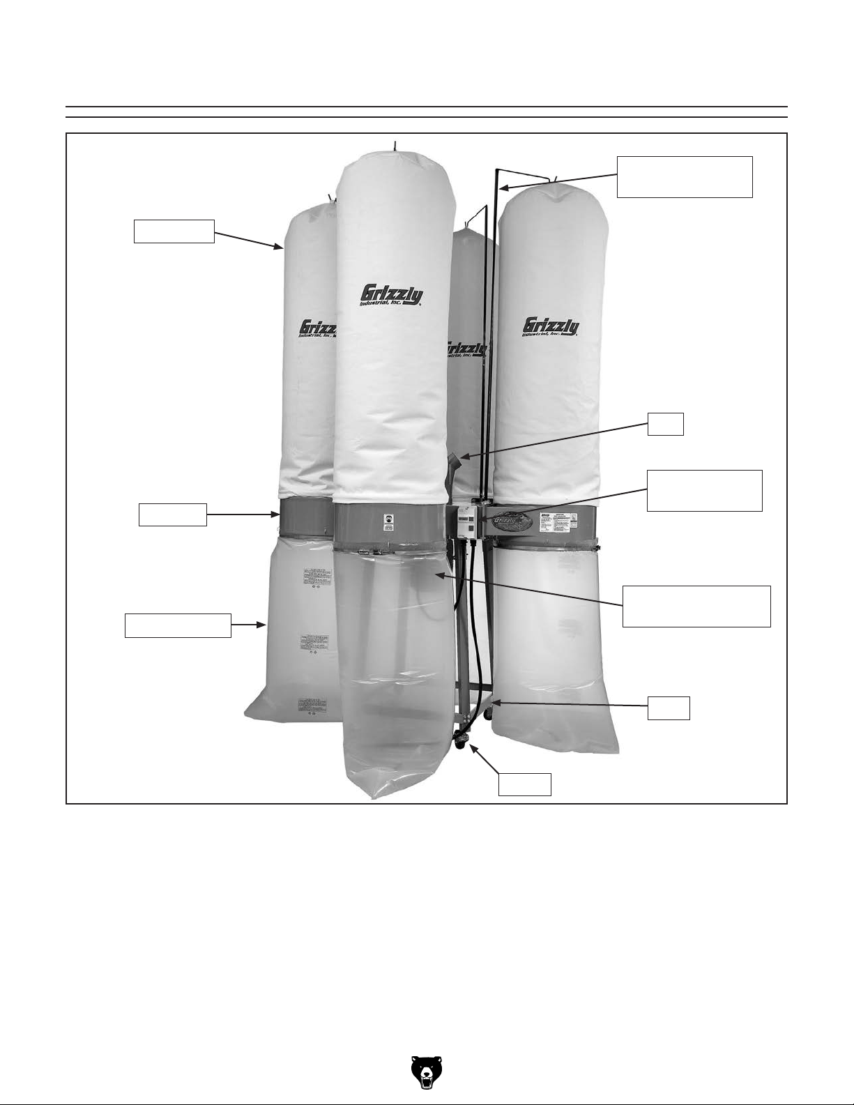
Upper Bag
Collector
Identification
Upper Bag Hanger
Assembly
Inlet
ON/OFF Power
Switch
Collection Bag
Motor
(Hidden From View)
Base
Caster
Figure 1. Model G0673 dust collector, front view.
Model G0671/G0672/G0673 (Mfg. Since 1/13
-3-
Page 6

MACHINE DATA
SHEET
Customer Service #: (570) 546-9663 · To Order Call: (800) 523-4777 · Fax #: (800) 438-5901
MODEL G0671 4 HP DUST COLLECTOR
Product Dimensions:
Weight.............................................................................................................................................................. 270 lbs.
Width (side-to-side) x Depth (front-to-back) x Height...................................................... 73-7/8 x 31-3/8 x 101-1/8 in.
Footprint (Length x Width)............................................................................................................... 73-7/8 x 31-3/8 in.
Shipping Dimensions:
Type............................................................................................................................ Cardboard Box & Wood Frame
Content........................................................................................................................................................... Machine
Weight.............................................................................................................................................................. 306 lbs.
Length x Width x Height....................................................................................................................... 42 x 29 x 30 in.
Must Ship Upright................................................................................................................................................... Yes
Electrical:
Power Requirement........................................................................................................... 220V, Single-Phase, 60 Hz
Prewired Voltage.................................................................................................................................................. 220V
Full-Load Current Rating........................................................................................................................................ 26A
Minimum Circuit Size.............................................................................................................................................. 40A
Connection Type....................................................................................................................... Permanent (Hardwire
Power Cord Included.............................................................................................................................................. Yes
Power Cord Length.......................................................................................................................................... N/A N/A
Power Cord Gauge.......................................................................................................................................... N/A N/A
Recommended Power Cord................................................................................................................................... N/A
Plug Included........................................................................................................................................................... No
Included Plug Type................................................................................................................................................. N/A
Recommended Plug Type...................................................................................................................................... N/A
Switch Type.................................................................................................... Magnetic Switch w/Overload Protection
Voltage Conversion Kit........................................................................................................................................... N/A
Inverter Type.......................................................................................................................................................... N/A
Inverter Size........................................................................................................................................................... N/A
Recommended Phase Converter........................................................................................................................... N/A
-4-
Motors:
Main
Type................................................................................................................. TEFC Capacitor-Start Induction
Horsepower................................................................................................................................................ 4 HP
Phase............................................................................................................................................ Single-Phase
Amps............................................................................................................................................................ 13A
Speed................................................................................................................................................ 3450 RPM
Power Transfer ............................................................................................................................... Direct Drive
Bearings..................................................................................................... Shielded & Permanently Lubricated
Model G0671/G0672/G0673 (Mfg. Since 1/13
Page 7

Main Specifications:
Operation
Dust Collector Type....................................................................................................................... Single-Stage
Approved Dust Types................................................................................................................................ Wood
Filter Type.................................................................................................................................................... Bag
Airflow Capacity................................................................................................................................ 3552 CFM
Max Static Pressure (at 0 CFM)............................................................................................................. 13.5 in.
Main Inlet Size........................................................................................................................................... 10 in.
Inlet Adapter Included.................................................................................................................................. Yes
Number of Adapter Inlets.................................................................................................................................. 4
Adapter Inlet Size........................................................................................................................................ 4 in.
Machine Collection Capacity At One Time....................................................................................................... 3
Maximum Material Collection Capacity................................................................................................. 24 cu. ft.
Filtration Rating................................................................................................................................... 30 Micron
Bag Information
No of Upper Bags............................................................................................................................................. 2
No of Lower Bags............................................................................................................................................. 2
Upper Bag Diameter............................................................................................................................ 23-5/8 in.
Upper Bag Length............................................................................................................................... 47-1/4 in.
Lower Bag Diameter............................................................................................................................ 23-5/8 in.
Lower Bag Length............................................................................................................................... 47-1/4 in.
Impeller Information
Impeller Type...................................................................................................................................... Radial Fin
Impeller Size........................................................................................................................................ 14-1/2 in.
Impeller Blade Thickness.......................................................................................................................... 1/4 in.
Construction
Upper Bag.................................................................................................................................... Woven Fabric
Lower Bag.................................................................................................................................... Woven Fabric
Frame.................................................................................................................... Steel Sheet Metal w/Casters
Impeller....................................................................................................................................................... Steel
Paint........................................................................................................................................... Powder Coated
Body....................................................................................................................................... Steel Sheet Metal
Other Specifications:
Country Of Origin ............................................................................................................................................. Taiwan
Warranty ........................................................................................................................................................... 1 Year
Approximate Assembly & Setup Time .............................................................................................................. 1 Hour
Serial Number Location ................................................................................................. ID Label on Front of Machine
Sound Rating ..................................................................................................................................................... 90 dB
ISO 9001 Factory .................................................................................................................................................. Yes
CSA Certified ......................................................................................................................................................... Yes
Features:
30 Micron Upper Bag Filtration
14-1/2" Balanced Steel, Radial Fin Impeller
Heavy-Duty Steel Stand with 3" Casters and Brakes
Green Powder Coated Paint
Sturdy Collection Bags with 24 cu. ft. Total Capacity
Four-Port Intake Manifold for Even Distribution to Collection Bags
Model G0671/G0672/G0673 (Mfg. Since 1/13
-5-
Page 8
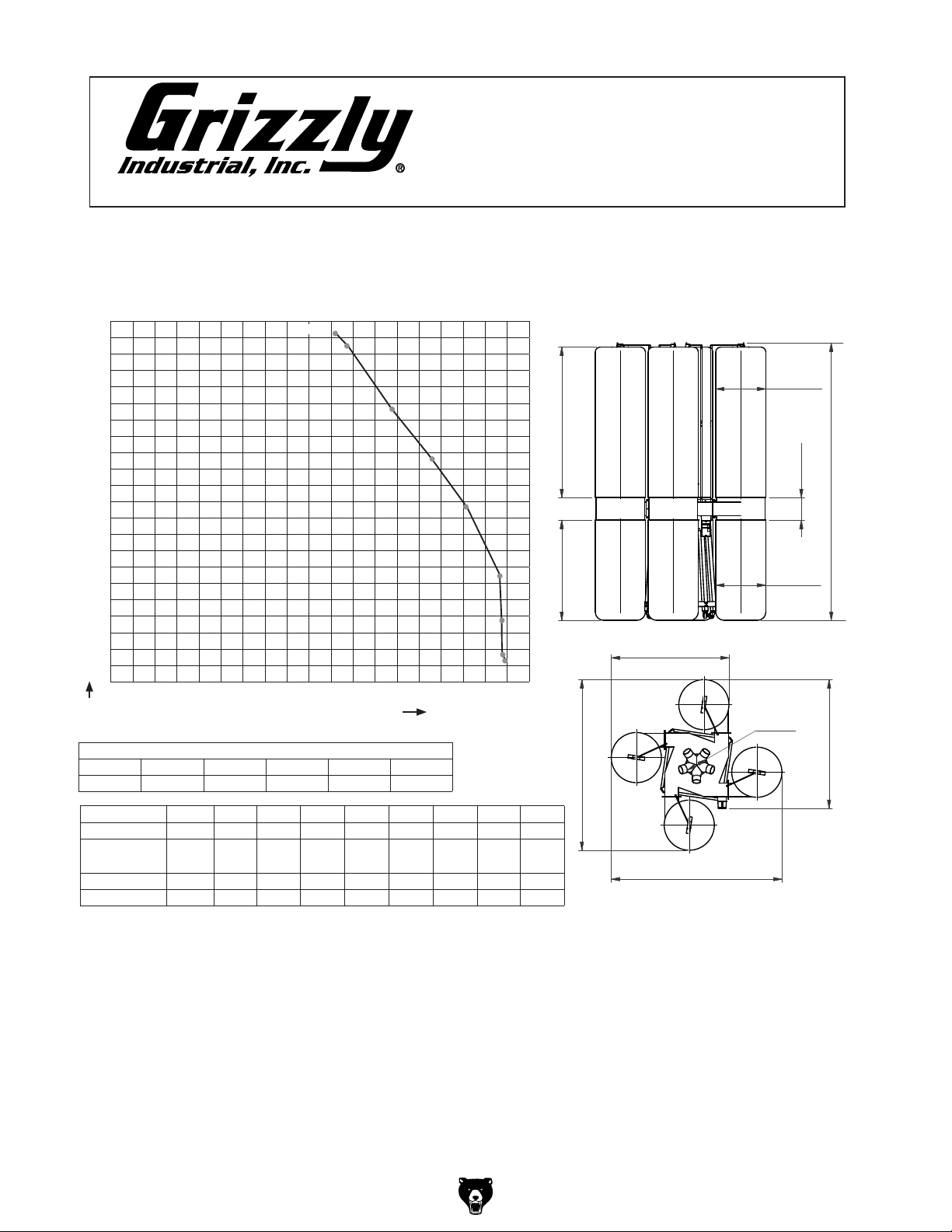
mACHINe dATA
1011/8"
4
"
4
"
Ø23
5
/8"
Ø23
5
/8"
6
5
/8"
SHeeT
Customer Service #: (570) 546-9663 • To Order Call: (800) 523-4777 • Fax #: (800) 438-5901
model G0671
4 HP dUST ColleCToR
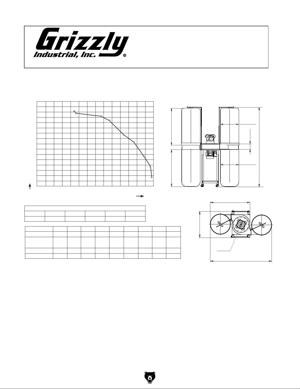
4000
Performance Curve
3750
3500
3250
3000
2750
2500
2250
2000
1750
1500
1250
1000
750
500
250
0
0 1.0 2.0 3.0 4.0 5.0 6.0 7.0 8.0 9.0 10.0 11.0 12.0 13.0 14.0
CFM
4 HP DUST COLLECTOR PERFORMANCE RESULTS
Max CFM Max SP HP Volts Inlet Impeller
3551.6 13.5 4 HP 220V 10" 14
Inlet Dia. (inch)
CFM
Static Pressure
(Inch/H2O)
Amps
Air Speed (m/s)
Test run using 30 micron upper and lower bag.
3552
471/4"
471/4"
STATIC PRESSURE (Inch/H2O)
1
/2"
10" 9" 8" 7" 6" 5" 4" 3" 2"
3551.6 3454.8 3282.6 2916.6 2475.4 2098.7 1452.9 979.4 484.3
4.72 4.82 6.98 8.5 10.3 11.1 12.53 13.2 13.5
30 29.5 27.5 24 21 16.8 12.5 11 8.6
33 32.1 30.5 27.1 23 19.5 13.5 9.1 4.5
313/
Ø235/8"
6 5/8"
1011/8"
Ø235/8"
"
475/
8
"
8
Ø10"
7
/8"
73
-6-
Model G0671/G0672/G0673 (Mfg. Since 1/13
Page 9

MACHINE DATA
SHEET
Customer Service #: (570) 546-9663 · To Order Call: (800) 523-4777 · Fax #: (800) 438-5901
MODEL G0672 5 HP INDUSTRIAL DUST COLLECTOR
Product Dimensions:
Weight.............................................................................................................................................................. 286 lbs.
Width (side-to-side) x Depth (front-to-back) x Height......................................................................... 74 x 29 x 134 in.
Footprint (Length x Width)............................................................................................................................ 74 x 29 in.
Shipping Dimensions:
Type............................................................................................................................ Cardboard Box & Wood Frame
Content........................................................................................................................................................... Machine
Weight.............................................................................................................................................................. 326 lbs.
Length x Width x Height....................................................................................................................... 42 x 29 x 30 in.
Must Ship Upright................................................................................................................................................... Yes
Electrical:
Power Requirement........................................................................................................... 220V, Single-Phase, 60 Hz
Prewired Voltage.................................................................................................................................................. 220V
Full-Load Current Rating........................................................................................................................................ 34A
Minimum Circuit Size.............................................................................................................................................. 50A
Connection Type....................................................................................................................... Permanent (Hardwire
Power Cord Included.............................................................................................................................................. Yes
Power Cord Length.......................................................................................................................................... N/A N/A
Power Cord Gauge.......................................................................................................................................... N/A N/A
Recommended Power Cord................................................................................................................................... N/A
Plug Included........................................................................................................................................................... No
Included Plug Type................................................................................................................................................. N/A
Recommended Plug Type...................................................................................................................................... N/A
Switch Type.................................................................................................... Magnetic Switch w/Overload Protection
Voltage Conversion Kit........................................................................................................................................... N/A
Inverter Type.......................................................................................................................................................... N/A
Inverter Size........................................................................................................................................................... N/A
Recommended Phase Converter........................................................................................................................... N/A
Motors:
Main
Type................................................................................................................. TEFC Capacitor-Start Induction
Horsepower................................................................................................................................................ 5 HP
Phase............................................................................................................................................ Single-Phase
Amps............................................................................................................................................................ 17A
Speed................................................................................................................................................ 3450 RPM
Power Transfer ............................................................................................................................... Direct Drive
Bearings..................................................................................................... Shielded & Permanently Lubricated
Model G0671/G0672/G0673 (Mfg. Since 1/13
-7-
Page 10

Main Specifications:
Operation
Dust Collector Type....................................................................................................................... Single-Stage
Approved Dust Types................................................................................................................................ Wood
Filter Type.................................................................................................................................................... Bag
Airflow Capacity................................................................................................................................. 3961 CFM
Max Static Pressure (at 0 CFM)............................................................................................................. 14.6 in.
Main Inlet Size........................................................................................................................................... 10 in.
Inlet Adapter Included.................................................................................................................................. Yes
Number of Adapter Inlets.................................................................................................................................. 4
Adapter Inlet Size........................................................................................................................................ 4 in.
Machine Collection Capacity At One Time....................................................................................................... 4
Maximum Material Collection Capacity................................................................................................. 24 cu. ft.
Filtration Rating.................................................................................................................................. 2.5 Micron
Bag Information
No of Upper Bags............................................................................................................................................. 2
No of Lower Bags............................................................................................................................................. 2
Upper Bag Diameter............................................................................................................................ 23-5/8 in.
Upper Bag Length...................................................................................................................................... 70 in.
Lower Bag Diameter............................................................................................................................ 23-5/8 in.
Lower Bag Length...................................................................................................................................... 54 in.
Impeller Information
Impeller Type...................................................................................................................................... Radial Fin
Impeller Size.............................................................................................................................................. 15 in.
Impeller Blade Thickness.......................................................................................................................... 1/4 in.
Construction
Upper Bag................................................................................................................................................ Fabric
Lower Bag................................................................................................................................................ Plastic
Frame.................................................................................................................... Steel Sheet Metal w/Casters
Caster..................................................................................................................................................... Rubber
Impeller....................................................................................................................................................... Steel
Paint........................................................................................................................................... Powder Coated
Blower Housing............................................................................................................................. Formed Steel
Other Specifications:
Country Of Origin ............................................................................................................................................. Taiwan
Warranty ........................................................................................................................................................... 1 Year
Approximate Assembly & Setup Time .............................................................................................................. 1 Hour
Serial Number Location ................................................................................................. ID Label on Front fo Machine
Sound Rating ..................................................................................................................................................... 92 dB
ISO 9001 Factory .................................................................................................................................................. Yes
CSA Certified ......................................................................................................................................................... Yes
Features:
2.5 Micron Upper Bag Filtration
15" Balanced Steel, Radial Fin Impeller
Heavy-Duty Steel Stand with 3" Casters and Brakes
Green Powder Coated Paint
Sturdy Collection Bags with 24 cu. ft. Total Capacity
Four-Port Intake Manifold for Even Distribution to Collection Bags
-8-
Model G0671/G0672/G0673 (Mfg. Since 1/13
Page 11
mACHINe dATA
134"
31
Ø23
5
/8"
Ø23
5
/8"
6
5
/8"
SHeeT
Customer Service #: (570) 546-9663 • To Order Call: (800) 523-4777 • Fax #: (800) 438-5901
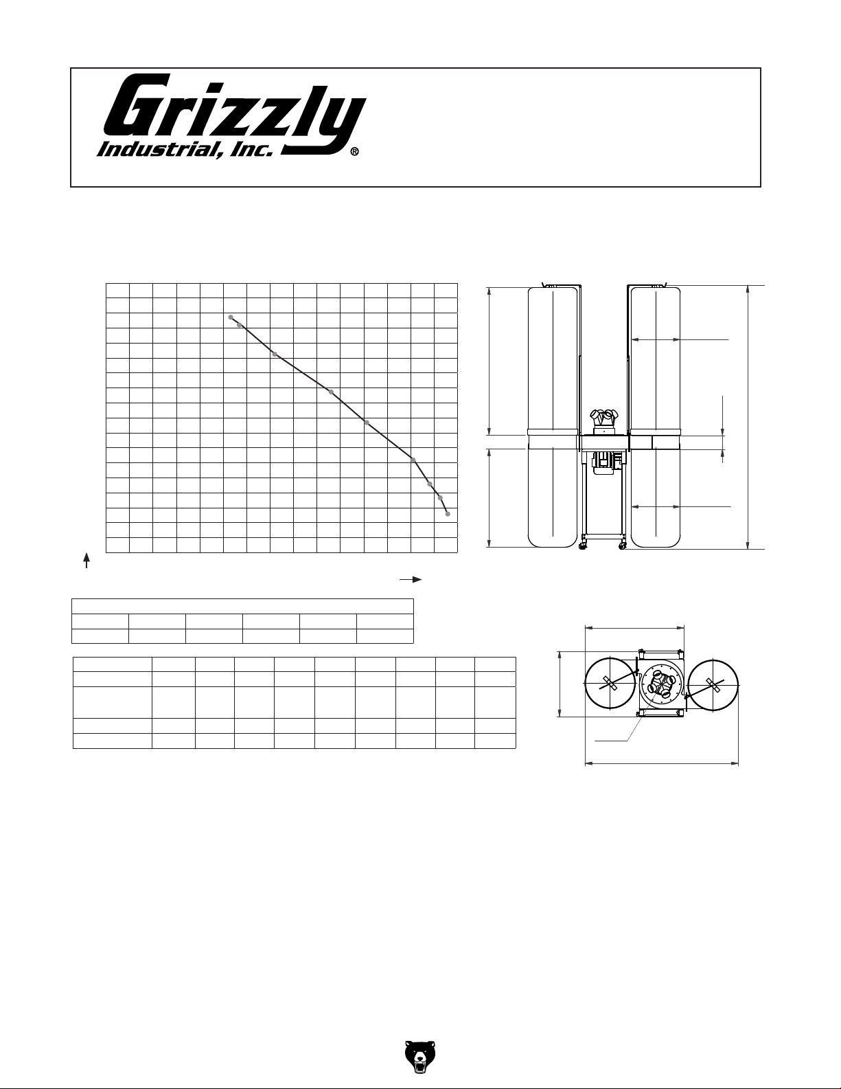
model G0672
5 HP dUST ColleCToR
Performance Curve
4500
4250
4000
3750
3500
3250
3000
2750
2500
2250
2000
1750
1500
1250
1000
750
500
250
0
0 1.0 2.0 3.0 4.0 5.0 6.0 7.0 8.0 9.0 10.0 11.0 12.0 13.0 14.0 15.0
CFM
3961
70"
57"
STATIC PRESSURE (Inch/H2O)
Ø23
6
Ø23
5
/8"
5
/8"
134"
5
/8"
5 HP DUST COLLECTOR PERFORMANCE RESULTS
Max CFM Max SP HP Volts Inlet Impeller
3960.6 14.6 5HP 220V 10" 15"
Inlet Dia. (inch)
CFM
Static Pressure
(Inch/H2O)
Amps
Air Speed (m/s)
Test run using 2.5 micron upper bag and plastic lower collection bag.
Max amp draw after adding 10" x 4" x 4 inlet: 30.3A.
10" 9" 8" 7" 6" 5" 4" 3" 2"
3960.6 3809.9 3336.4 2744.4 2206.3 1560.6 1140.8 861.0 656.5
5.36 5.6 7.2 9.64 11.4 13.04 13.84 14.08 14.6
33.2 32.5 30 25.5 21.7 17.4 13.5 10.7 9.5
36.8 35.4 31 25.5 20.5 14.5 10.6 8 6.1
5
"
47
/
8
3
"
/
8
Ø10"
737/8"
Model G0671/G0672/G0673 (Mfg. Since 1/13
-9-
Page 12

MACHINE DATA
SHEET
Customer Service #: (570) 546-9663 · To Order Call: (800) 523-4777 · Fax #: (800) 438-5901
MODEL G0673 10 HP INDUSTRIAL DUST COLLECTOR
Product Dimensions:
Weight.............................................................................................................................................................. 410 lbs.
Width (side-to-side) x Depth (front-to-back) x Height......................................................................... 61 x 61 x 134 in.
Footprint (Length x Width)............................................................................................................................ 61 x 61 in.
Shipping Dimensions:
Type............................................................................................................................ Cardboard Box & Wood Frame
Content........................................................................................................................................................... Machine
Weight.............................................................................................................................................................. 472 lbs.
Length x Width x Height....................................................................................................................... 53 x 46 x 31 in.
Must Ship Upright................................................................................................................................................... Yes
Electrical:
Power Requirement..................................................................................................... 220V or 440V, 3-Phase, 60 Hz
Prewired Voltage.................................................................................................................................................. 220V
Full-Load Current Rating..................................................................................................... 30A at 220V, 15A at 440V
Minimum Circuit Size.......................................................................................................... 40A at 220V, 20A at 440V
Connection Type....................................................................................................................... Permanent (Hardwire
Power Cord Included.............................................................................................................................................. N/A
Power Cord Length.......................................................................................................................................... N/A N/A
Power Cord Gauge.......................................................................................................................................... N/A N/A
Recommended Power Cord................................................................................................................................... N/A
Plug Included.......................................................................................................................................................... N/A
Included Plug Type................................................................................................................................................. N/A
Recommended Plug Type...................................................................................................................................... N/A
Switch Type.................................................................................................... Magnetic Switch w/Overload Protection
Voltage Conversion Kit.................................................................................................................. P0508037 for 440V
Inverter Type.......................................................................................................................................................... N/A
Inverter Size........................................................................................................................................................... N/A
Recommended Phase Converter....................................................................................................................... G7979
-10 -
Motors:
Main
Type........................................................................................................................................... TEFC Induction
Horsepower.............................................................................................................................................. 10 HP
Phase.................................................................................................................................................... 3-Phase
Amps..................................................................................................................................................... 30A/15A
Speed................................................................................................................................................ 3450 RPM
Power Transfer ............................................................................................................................... Direct Drive
Bearings..................................................................................................... Shielded & Permanently Lubricated
Model G0671/G0672/G0673 (Mfg. Since 1/13
Page 13

Main Specifications:
Operation
Dust Collector Type....................................................................................................................... Single-Stage
Approved Dust Types................................................................................................................................ Wood
Filter Type.................................................................................................................................................... Bag
Airflow Capacity................................................................................................................................. 5360 CFM
Max Static Pressure (at 0 CFM)............................................................................................................. 17.9 in.
Main Inlet Size........................................................................................................................................... 10 in.
Inlet Adapter Included.................................................................................................................................. Yes
Number of Adapter Inlets.................................................................................................................................. 5
Adapter Inlet Size........................................................................................................................................ 4 in.
Machine Collection Capacity At One Time....................................................................................................... 4
Maximum Material Collection Capacity................................................................................................. 48 cu. ft.
Filtration Rating.................................................................................................................................. 2.5 Micron
Bag Information
No of Upper Bags............................................................................................................................................. 4
No of Lower Bags............................................................................................................................................. 4
Upper Bag Diameter............................................................................................................................ 23-5/8 in.
Upper Bag Length...................................................................................................................................... 70 in.
Lower Bag Diameter............................................................................................................................ 23-5/8 in.
Lower Bag Length...................................................................................................................................... 54 in.
Impeller Information
Impeller Type...................................................................................................................................... Radial Fin
Impeller Size.............................................................................................................................................. 17 in.
Impeller Blade Thickness.......................................................................................................................... 1/4 in.
Construction
Upper Bag................................................................................................................................................ Fabric
Lower Bag................................................................................................................................................ Plastic
Frame.................................................................................................................... Steel Sheet Metal w/Casters
Caster..................................................................................................................................................... Rubber
Impeller....................................................................................................................................................... Steel
Paint........................................................................................................................................... Powder Coated
Blower Housing............................................................................................................................. Formed Steel
Other Specifications:
Country Of Origin ............................................................................................................................................. Taiwan
Warranty ........................................................................................................................................................... 1 Year
Approximate Assembly & Setup Time ...................................................................................................... 1-1/2 Hours
Serial Number Location ................................................................................................. ID Label on Front fo Machine
ISO 9001 Factory .................................................................................................................................................. Yes
CSA Certified .......................................................................................................................................................... No
Features:
2.5 Micron Upper Bag Filtration
17" Balanced Steel, Radial Fin Impeller
Heavy-Duty Steel Stand with 3" Casters and Brakes
Green Powder Coated Paint
Sturdy Collection Bags with 48 cu. ft. Total Capacity
Five-Port Intake Manifold for Even Distribution to Collection Bags
Model G0671/G0672/G0673 (Mfg. Since 1/13
-11-
Page 14
Customer Service #: (570) 546-9663 • To Order Call: (800) 523-4777 • Fax #: (800) 438-5901
model G0673
10 HP dUST ColleCToR
Performance Curve
5500
5250
5000
4750
4500
4250
4000
3750
3500
3250
3000
2750
2500
2250
2000
1750
1500
1250
1000
750
500
250
0
0 1.0 2.0 3.0 4.0 5.0 6.0 7.0 8.0 9.0 10.0 11.0 12.0 13.0 14.0 15.0 16.0 17.0 18.0 19.0
CFM
10 HP DUST COLLECTOR PERFORMANCE RESULTS
Max CFM Max SP HP Volts Inlet Impeller
5359.7 17.9 10HP 220V 10" 17"
STATIC PRESSURE (Inch/H2O)
5359.7
mACHINe dATA
SHeeT
Ø23
70"
1
/2"
8
57
80
"
1
"
55
/
2
3
"
/
8
Ø23
Ø10"
5
/8"
1
135
/2"
5
/8"
5
"
/
60
8
Inlet Dia. (inch)
CFM
Static Pressure
(Inch/H2O)
Amps
Air Speed (m/s)
Test run using 2.5 micron upper bag and plastic lower collection bag.
Max amp draw after adding 10" x 4" x 5 inlet: 30.5A.
10" 9" 8" 7" 6" 5" 4" 3" 2"
5359.7 5176.8 4229.7 3390.2 2604.5 1678.9 968.6 430.5 344.4
10.08 10.64 12.96 14.72 16.08 17.68 17.72 17.8 17.9
32.6 32.1 30 26.6 23.1 18.7 15.4 13.1 12
49.8 48.1 39.3 31.5 24.2 15.6 9 4 3.2
-12-
3
"
80
/
8
Model G0671/G0672/G0673 (Mfg. Since 1/13
Page 15
SECTION 1: SAFETY
For Your Own Safety, Read Instruction
Manual Before Operating This Machine
The purpose of safety symbols is to attract your attention to possible hazardous conditions.
This manual uses a series of symbols and signal words intended to convey the level of importance of the safety messages. The progression of symbols is described below. Remember that
safety messages by themselves do not eliminate danger and are not a substitute for proper
accident prevention measures. Always use common sense and good judgment.
Indicates an imminently hazardous situation which, if not avoided,
WILL result in death or serious injury.
Indicates a potentially hazardous situation which, if not avoided,
COULD result in death or serious injury.
Indicates a potentially hazardous situation which, if not avoided,
MAY result in minor or moderate injury. It may also be used to alert
against unsafe practices.
This symbol is used to alert the user to useful information about
NOTICE
proper operation of the machine.
Safety Instructions for Machinery
OWNER’S MANUAL. Read and understand this
owner’s manual BEFORE using machine.
TRAINED OPERATORS ONLY. Untrained operators have a higher risk of being hurt or killed.
Only allow trained/supervised people to use this
machine. When machine is not being used, disconnect power, remove switch keys, or lock-out
machine to prevent unauthorized use—especially
around children. Make workshop kid proof!
DANGEROUS ENVIRONMENTS. Do not use
machinery in areas that are wet, cluttered, or have
poor lighting. Operating machinery in these areas
greatly increases the risk of accidents and injury.
MENTAL ALERTNESS REQUIRED. Full mental
alertness is required for safe operation of machinery. Never operate under the influence of drugs or
alcohol, when tired, or when distracted.
ELECTRICAL EQUIPMENT INJURY RISKS. You
can be shocked, burned, or killed by touching live
electrical components or improperly grounded
machinery. To reduce this risk, only allow qualified
service personnel to do electrical installation or
repair work, and always disconnect power before
accessing or exposing electrical equipment.
DISCONNECT POWER FIRST.
nect machine from power supply BEFORE making
adjustments, changing tooling, or servicing machine.
This prevents an injury risk from unintended startup
or contact with live electrical components.
EYE PROTECTION. Always wear ANSI-approved
safety glasses or a face shield when operating or
observing machinery to reduce the risk of eye
injury or blindness from flying particles. Everyday
eyeglasses are NOT approved safety glasses.
Always discon-
Model G0671/G0672/G0673 (Mfg. Since 1/13
-13-
Page 16

WEARING PROPER APPAREL. Do not wear
clothing, apparel or jewelry that can become
entangled in moving parts. Always tie back or
cover long hair. Wear non-slip footwear to avoid
accidental slips, which could cause loss of workpiece control.
HAZARDOUS DUST. Dust created while using
machinery may cause cancer, birth defects, or
long-term respiratory damage. Be aware of dust
hazards associated with each workpiece material,
and always wear a NIOSH-approved respirator to
reduce your risk.
HEARING PROTECTION. Always wear hearing protection when operating or observing loud
machinery. Extended exposure to this noise
without hearing protection can cause permanent
hearing loss.
REMOVE ADJUSTING TOOLS. Tools left on
machinery can become dangerous projectiles
upon startup. Never leave chuck keys, wrenches,
or any other tools on machine. Always verify
removal before starting!
USE CORRECT TOOL FOR THE JOB. Only use
this tool for its intended purpose—do not force
it or an attachment to do a job for which it was
not designed. Never make unapproved modifications—modifying tool or using it differently than
intended may result in malfunction or mechanical
failure that can lead to personal injury or death!
AWKWARD POSITIONS. Keep proper footing
and balance at all times when operating machine.
Do not overreach! Avoid awkward hand positions
that make workpiece control difficult or increase
the risk of accidental injury.
CHILDREN & BYSTANDERS. Keep children and
bystanders at a safe distance from the work area.
Stop using machine if they become a distraction.
FORCING MACHINERY. Do not force machine.
It will do the job safer and better at the rate for
which it was designed.
NEVER STAND ON MACHINE. Serious injury
may occur if machine is tipped or if the cutting
tool is unintentionally contacted.
STABLE MACHINE. Unexpected movement during operation greatly increases risk of injury or
loss of control. Before starting, verify machine is
stable and mobile base (if used) is locked.
USE RECOMMENDED ACCESSORIES. Consult
this owner’s manual or the manufacturer for recommended accessories. Using improper accessories will increase the risk of serious injury.
UNATTENDED OPERATION. To reduce the
risk of accidental injury, turn machine OFF and
ensure all moving parts completely stop before
walking away. Never leave machine running
while unattended.
MAINTAIN WITH CARE. Follow all maintenance
instructions and lubrication schedules to keep
machine in good working condition. A machine
that is improperly maintained could malfunction,
leading to serious personal injury or death.
CHECK DAMAGED PARTS. Regularly inspect
machine for any condition that may affect safe
operation. Immediately repair or replace damaged
or mis-adjusted parts before operating machine.
MAINTAIN POWER CORDS. When disconnecting cord-connected machines from power, grab
and pull the plug—NOT the cord. Pulling the cord
may damage the wires inside. Do not handle
cord/plug with wet hands. Avoid cord damage by
keeping it away from heated surfaces, high traffic
areas, harsh chemicals, and wet/damp locations.
GUARDS & COVERS. Guards and covers reduce
accidental contact with moving parts or flying
debris. Make sure they are properly installed,
undamaged, and working correctly.
-14-
EXPERIENCING DIFFICULTIES. If at any time
you experience difficulties performing the intended operation, stop using the machine! Contact our
Technical Support at (570) 546-9663.
Model G0671/G0672/G0673 (Mfg. Since 1/13
Page 17
Additional Safety for Dust Collectors
1. MACHINE USE. This machine only is
intended to collect wood dust/chips from
woodworking machines. Do not use this
dust collector as a vacuum. Do not use
this dust collector with machines producing
dust/chips from metal, asbestos products,
lead paint, silica or any products that are
not natural wood or man-made wood products such as plywood or particle board.
2. WEAR RESPIRATOR. This machine may
blow fine dust particles into the air during operation. Always wear an approved
respirator during and for a short time after
machine operation!
3. SUSPENDED DUST PARTICLES AND
IGNITION SOURCES. Do not operate the
dust collector in areas where explosion
risks would be high if dust were dispersed
into the area. Areas of high risk include, but
are not limited to, areas near pilot lights or
open flames.
4. EMPTYING DUST. When emptying dust
from the collection bags or drum, wear a
respirator and safety glasses. Empty dust
into an approved container and dispose of
properly.
5. SAFE SERVICING. Disconnect power and
allow impeller to completely stop before
servicing or working on the dust collector
or the ducting system, especially if clearing
a clogged duct.
6. AVOIDING FIRES. Do not allow steel to
strike against the impeller—this may produce a spark. Sparks can smolder in wood
dust for a long time before fire or flame is
detected. If you accidentally collect metal
during operation, immediately turn off the
dust collector, unplug the power cord from
the outlet or flip the disconnect switch and
wait for all moving parts to stop. Remove
collection bags and empty the dust into an
approved air tight metal container. Prevent
any chance of accidentally collecting metal
again before resuming operations.
7. KEEPING FINGERS SAFE. Do not place
your hands or tools near the open inlet during operation for any reason. The powerful
suction could cause accidental contact with
the impeller which will cause serious personal injury or damage to the machine.
8. OPERATIONAL QUESTIONS. If at any
time you are experiencing difficulties
performing the intended operation, stop
using the machine! Then contact our Tech
Support or ask a qualified expert how the
operation should be performed.
9. DUST HAZARD. Be aware that certain
woods may cause an allergic reaction
in people and animals, especially when
exposed to fine dust. Make sure you know
what type of wood dust you will be exposed
to in case there is a possibility of an allergic
reaction.
Like all machines there is danger associated
with this machine. Accidents are frequently
caused by lack of familiarity or failure to pay
attention. Use this machine with respect
and caution to lessen the possibility of
operator injury. If normal safety precautions
are overlooked or ignored, serious personal
injury may occur.
Model G0671/G0672/G0673 (Mfg. Since 1/13
No list of safety guidelines can be complete.
Every shop environment is different. Always
consider safety first, as it applies to your
individual working conditions. Use this and
other machinery with caution and respect.
Failure to do so could result in serious personal injury, damage to equipment, or poor
work results.
-15-
Page 18

SECTION 2: CIRCUIT REQUIREMENTS
Operation
Serious personal injury could occur if you
connect the machine to power before completing the setup process. DO NOT connect
the machine to the power until instructed
later in this manual.
Electrocution or fire could
result if machine is not
grounded and installed in
compliance with electrical
codes. Compliance MUST
be verified by a qualified
electrician!
Power Supply Circuit Requirements
The power supply circuit for your machine MUST
be grounded and rated for the amperage given
below. Never replace a circuit breaker on an existing circuit with one of higher amperage without
consulting a qualified electrician to ensure compliance with wiring codes. If you are unsure about
the wiring codes in your area or you plan to
connect your machine to a shared circuit, consult a qualified electrician.
G0671 Minimum Circuit Size .................40 Amps
G0672 Minimum Circuit Size .................50 Amps
G0673 Minimum Circuit Size (220V) .....40 Amps
G0673 Minimum Circuit Size (440V) .....20 Amps
Power Connection Device
We recommend having an electrician hardwire
the machine (using a metal conduit setup) directly
to a locking disconnect switch (Figure 2), which is
directly connected to the power source.
NOTICE
The Model G0671/G0672/G0673 is prewired
for 220V operation. If you plan to use your
Model G0673 at 440V, you MUST have a
qualified electrican perform the 440V conversion described on this page.
Full Load Amperage Draw
G0671 @ 220V ..................................... 32 Amps
G0672 @ 220V .....................................34 Amps
G0673 @ 220V .....................................30 Amps
G0673 @ 440V ..................................... 15 Amps
Hardwired Locking
Disconnect Switch
Figure 2. Hardwired locking disconnect switch.
440V Conversion
The Model G0673 can be converted for 440V
operation. This conversion job consists of disconnecting the dust collector from the power source,
changing the magnetic switch, and rewiring the
motor for 440V operation, as shown on Page 42.
The necessary magnetic switch for this procedure
can be purchased by calling Grizzly Customer
Service at (800) 523-4777 and ordering Model
G8296 (3-Phase 440V 10HP Mag Switch).
All wiring changes must be inspected by a qualified electrician before the dust collector is connected to the power source. If, at any time during
this procedure you need help, call Grizzly Tech
Support at (570) 546-9663.
-16 -
Model G0671/G0672/G0673 (Mfg. Since 1/13
Page 19

SECTION 3: SETUP
Needed for Setup
This machine presents
serious injury hazards
to untrained users. Read
through this entire manual to become familiar with
the controls and operations before starting the
machine!
Wear safety glasses during the entire setup process!
The following are needed to complete the setup
process, but are not included with your machine:
Description Qty
• Assistant ........................................1 or more
• Safety Glasses (for each person) ............... 1
• Gloves (for each person) ............................ 1
• Phillips Head Screwdriver........................... 1
• Wrench 10mm ............................................ 1
• Wrenches 12mm ........................................ 2
• Ladder (for hanging upper bag) .................. 1
Unpacking
This machine and its components are very heavy.
Get lifting help or use
power lifting equipment
such as a forklift to move
heavy items.
Your machine was carefully packaged for safe
transportation. Remove the packaging materials
from around your machine and inspect it. If you
discover the machine is damaged, please imme-
diately call Customer Service at (570) 546-9663
for advice.
Save the containers and all packing materials for
possible inspection by the carrier or its agent.
Otherwise, filing a freight claim can be difficult.
When you are completely satisfied with the condition of your shipment, inventory the contents.
Model G0671/G0672/G0673 (Mfg. Since 1/13
-17-
Page 20

G0671/G0672
Inventory
The following is a description of the main components shipped with your machine. Lay the components out to inventory them.
A
B
C
Note: If you can't find an item on this list, check
the mounting location on the machine or examine
the packaging materials carefully. Occasionally
we pre-install certain components for shipping
purposes.
Contents (Figures 3 & 4) Qty
A. Collectors ................................................... 2
B. Impeller Housing with Motor ....................... 1
C. Casters ....................................................... 4
D. Leg Braces ................................................. 4
E. Legs ............................................................ 4
F. Gaskets ...................................................... 2
G. 4-in-1 Inlet Adapter ..................................... 1
H. Hangers ...................................................... 2
I. Hanger Supports ........................................ 2
J. Lower Collection Bags, G0671 (fabric) ....... 2
J. Lower Collection Bags, G0672 (plastic) ..... 2
K. Upper Filter Bags (fabric) ........................... 2
Fasteners (where used) (not shown) Qty
5
• Hex Bolts
• Hex Nuts
• Hex Bolts
• Hex Bolts
• Hex Bolts
• Flat Washers
• Phillips Head Screw 10-24 X
⁄16"-18 x 2 1⁄2 " (legs) .................... 8
5
⁄16"-18 (legs/collectors) ............. 24
5
⁄16"-18 x 1⁄2 " (leg braces) .......... 16
5
⁄16"-18 x 1" (collectors) ............. 16
1
⁄4"-20 x 1⁄2 " (hangers) ................. 6
5
⁄16" (collectors) ................... 32
3
⁄8" (inlet) ...... 1
• Bag Clamps (bags) ..................................... 4
E
D
Figure 3. G0671/G0672 inventory 1.
H
I
G
J
F
K
Figure 4. G0671/G0672 inventory 2.
If any nonproprietary parts are missing (e.g. a
nut or a washer), we will gladly replace them; or
for the sake of expediency, replacements can be
obtained at your local hardware store.
-18-
Model G0671/G0672/G0673 (Mfg. Since 1/13
Page 21

G0673 Inventory
The following is a description of the main components shipped with your machine. Lay the components out to inventory them.
Note: If you can't find an item on this list, check
the mounting location on the machine or examine
the packaging materials carefully. Occasionally
we pre-install certain components for shipping
purposes.
G
H
I
J
Contents (Figures 5–7) Qty
A. Collectors ................................................... 4
B. 5-in-1 Inlet Adapter ..................................... 1
C. G0673 Impeller Housing with Motor ........... 1
D. Legs ............................................................ 4
E. Leg Braces ................................................. 4
F. Casters ....................................................... 4
G. Upper Filter Bags (fabric) ........................... 4
H. Lower Collection Bags (plastic) .................. 4
I. Hangers ...................................................... 4
J. Hanger Supports ........................................ 4
K. Rubber Gaskets ......................................... 4
L. Bag Clamps ................................................ 8
Fasteners (where used) (not shown) Qty
5
• Hex Bolts
• Hex Nuts
• Hex Bolts
• Hex Bolts
• Hex Bolts
• Flat Washers
• Phillips Head Screw 10-24 X
⁄16"-18 x 2 1⁄2 " (legs) .................... 8
5
⁄16"-18" (legs/collectors) ............ 40
5
⁄16"-18 x 1⁄2 " (leg braces) .......... 16
5
⁄16"-18 x 1" (collectors) ............. 32
1
⁄4"-20 x 1⁄2 " (hangers) ............... 12
5
⁄16" (collectors) ................... 64
3
⁄8" (inlet) ...... 1
Figure 6. G0673 inventory 2.
K
L
Figure 7. G0673 inventory 3.
If any nonproprietary parts are missing (e.g. a
nut or a washer), we will gladly replace them; or
for the sake of expediency, replacements can be
obtained at your local hardware store.
B
C
A
E
D
F
Figure 5. G0673 inventory 1.
Model G0671/G0672/G0673 (Mfg. Since 1/13
-19 -
Page 22

Hardware Recognition Chart
-20-
Model G0671/G0672/G0673 (Mfg. Since 1/13
Page 23

Site Considerations
Assembly
Floor Load
Refer to the Machine Data Sheet for the weight
and footprint specifications of your machine.
Some residential floors may require additional
reinforcement to support both the machine and
operator.
Placement Location
Consider existing and anticipated needs, size of
material to be processed through each machine,
and space for auxiliary stands, work tables or
other machinery when establishing a location for
your new machine. See Figure 8 for the minimum
working clearances.
7
⁄8"
73
3
⁄8"
31
G0671/G0672
To assemble the dust collector:
1. With assistance, place the impeller housing
on the floor so that the motor is pointing up.
2. Insert the legs into the leg mounting brackets
5
and secure them with the eight
5
hex bolts and
⁄16"-18 hex nuts, as shown in
⁄16"-18 x 2 1⁄2"
Figure 9. Do not yet fully tighten the nuts.
Leg
x8
Leg Mounting Bracket
803⁄8"
3
⁄8"
80
G0673
Figure 8. Model G0671-3 illustrated top view
and suggested clearances.
Children and visitors may be
seriously injured if unsupervised around this machine.
Lock entrances to the shop
or disable start switch or
power connection to prevent
unsupervised use.
Figure 9. Attaching legs to impeller housing
(Model G0673 shown).
3. Attach the four leg braces to the legs with
the (16)
5
⁄16"-18 x 1⁄2" hex bolts, as shown in
Figure 10. Fully tighten the bolts and the
hardware from Step 2.
Leg
Leg Brace
x16
Figure 10. Attaching leg braces.
Model G0671/G0672/G0673 (Mfg. Since 1/13
-21-
Page 24

4. Attach the four casters to the legs by thread-
ing them into the bottom of the legs, as
shown in Figure 11.
Caster
Leg
x4
Figure 11. Attaching casters.
5. With assistance, turn the entire assembly
over so that the casters rest on the floor.
5
6. Use eight
washers, and eight
⁄16"-18 x 1" hex bolts, (16) 5⁄16" flat
5
⁄16"-18 hex nuts to attach
each collector to the impeller housing with a
rubber gasket between the components, as
shown in Figure 12.
Note: The Model G0673 is a three-phase
machine. If it is wired out of phase, the
machine may not function properly. Proceed
to Test Run on Page 25 to determine if your
machine is wired in phase, then proceed to
Step 7.
The Models G0671 and G0672 are single
phase and cannot be wired out of phase. For
these models, continue below.
7. Attach the inlet to the top of the impeller
housing with the #10-24 x 3/8" Phillips head
screw, as shown in Figure 13.
Phillips
Head Screw
5
⁄16" Flat Washers
Impeller
housing
Collector
5
⁄16"-18
Hex Nut
5
⁄16"-18 x 1"
Hex Bolt
Rubber Gasket
Figure 12. Collector mounted to impeller
housing.
Figure 13. Inlet mounted on impeller housing.
-22-
Model G0671/G0672/G0673 (Mfg. Since 1/13
Page 25

8. Secure the hanger into the hanger sup-
port with one (Model G0673) or two (Model
1
G0671/G0672)
⁄4"-20 x 1⁄2" hex bolts (see
Figure 14).
10. Align the hanger assembly so that the hook is
directly over the center of the collector.
11. Repeat Steps 8–10 for the remaining hanger
assemblies.
Hex Bolts
1
Hanger
⁄4"-20 x 1⁄2"
Hanger Support
Figure 14. Hanger attached to hanger support
(G061/G0672 shown).
9. Mount the hanger assembly on the protruding
rod on the collector with one (Model G0671/
1
G0672) or two (Model G0673)
⁄4"-20 x 1⁄2"
hex bolts, as shown in Figure 15.
Hanger
Assembly
12. Place the loop at the top of each upper col-
lection bag over each hook on the hanger
assemblies (see Figure 16).
Hook
Bag Loop
Hanger
Assembly
Figure 16. Upper filter bag mounted on hanger
assembly.
13. Thread the bag clamp into and around the
bottom seam of the upper collection bag (see
Figure 17).
Hex Bolt
1
⁄4"-20 x 1⁄2"
Figure 15. Hanger assembly mounted onto
collector (G0671/G0672).
Model G0671/G0672/G0673 (Mfg. Since 1/13
Bag Clamp
Figure 17. Upper filter bag secured to collector.
-23-
Page 26

14. Slip the bottom of the bag with the clamp over
the top lip of the collector.
15. Fasten the locking mechanism of the bag
clamp to secure the bag to the collector (see
Figure 17).
16. Repeat Steps 12-15 for the remaining upper
bags.
17. Install the lower bags.
—Model G0671: Repeat Steps 13-15 in
a similar manner to install the remaining
lower collection bags on the lower rims of
each collector. Then, proceed to Test Run
on Page 25.
18. Wrap the bag clamp around the collector,
position it between the bottom lip of the collector and the hooks, and fasten the bag
clamp to secure the bag to the collector (see
Figure 19).
— Model G0672-73: Slip the lower plastic
collection bag over the bottom lip of the collector and position the bag evenly around
the collector. Snag the bag on the hooks to
hold it in place until the bag clamp can be
secured (see Figure 18).
Collector Hook
Figure 18. Bottom collection bag snagged on
collector hooks.
Bag Clamp
Figure 19. Lower collection bag secured to
collector.
19. Repeat Steps 17 & 18 for the remaining
Model G0672-73 lower bag assemblies.
-24-
Model G0671/G0672/G0673 (Mfg. Since 1/13
Page 27

Test Run
5. Listen to and watch for abnormal noises or
actions. The machine should run smoothly
with little or no vibration or rubbing noises.
Once the assembly is complete, test run your
machine to make sure it runs properly and is
ready for regular operation.
The test run consists of verifying the following: 1)
The motor powers up and runs correctly, and 2)
(Model G0673 only), the motor turns the correct
direction (machine is not wired out of phase).
If, during the test run, you cannot easily locate
the source of an unusual noise or vibration, stop
using the machine immediately, then review the
Troubleshooting on Page 38.
If you still cannot remedy a problem, contact our
Tech Support at (570) 546-9663 for assistance.
Before starting the dust collector, make
sure you have performed the preceding
assembly instructions, and you have read
through the rest of the manual and are
familiar with the various functions and
safety features on this machine. Failure to
follow this warning could result in serious
personal injury or even death!
— Strange or unusual noises should be inves-
tigated and corrected before operating the
machine further. Always disconnect the
machine from power when investigating or
correcting potential problems.
6. Turn the machine OFF by pushing in the RED
button on the power switch.
7. Model G0673 Only: Verify that the power
is not connected out of phase by starting/
stopping the machine and determining if the
motor turns in the correct direction, using the
criteria below:
— If the impeller turns counterclockwise
(when looking down on the inlet port on the
impeller housing), it is turning in the correct
direction.
— If the impeller turns clockwise, it is turning
in the wrong direction. Stop the machine,
shut off the power source, then swap any
two of the three power wires that connect
to the machine.
To test run the machine:
1. Make sure you have read the safety instruc-
tions at the beginning of the manual and that
the machine is setup properly.
2. Make sure all tools and objects used during
setup are cleared away from the machine.
3. Connect the machine to the power source.
4. Turn the machine ON by pushing in the
GREEN button on the power switch.
Model G0671/G0672/G0673 (Mfg. Since 1/13
-25-
Page 28
SECTION 4: DESIGNING THE
SYSTEM
General
The Model G0671/G0672/G0673 can be operated
as either a stationary or mobile unit. There are
advantages and disadvantages to both set-ups.
The advantage of the mobile system is eliminating
the cost of many ducts and fittings. On the other
hand, the stationary system is more versatile and
convenient.
The Model G0671/G0672/G0673 is designed to
be a central dust collector system. Locate the dust
collector in an out of the way location such as a
corner or separate room. These machines can
accommodate the following number of machines
each drawing 400 CFM on a 4" dust port:
G0671: ............................................................... 8
G0672: ............................................................... 9
G0673: ............................................................. 12
The large suction capacity of the Model G0671/
G0672/G0673 allows great flexibility in planning
and designing of your dust collection duct layout.
Grizzly offers a complete line of dust collection
accessories for setting up a stationary system.
Additionally, Grizzly offers a complete guide book
titled Dust Collection Basics.
Duct Material
You have many choices regarding main line and
branch line duct material. For best results, use
metal duct for the main line and branch lines, then
use short lengths of flexible hose to connect each
machine to the branch lines.
Plastic duct is also a popular material for home
shops. However, be aware that there is a fire or
explosion hazard if plastic duct material is used
for dust collection without being grounded against
static electrical charge build-up. This topic will be
discussed later in this section. Another problem
with using plastic is that it is less efficient per foot
than metal.
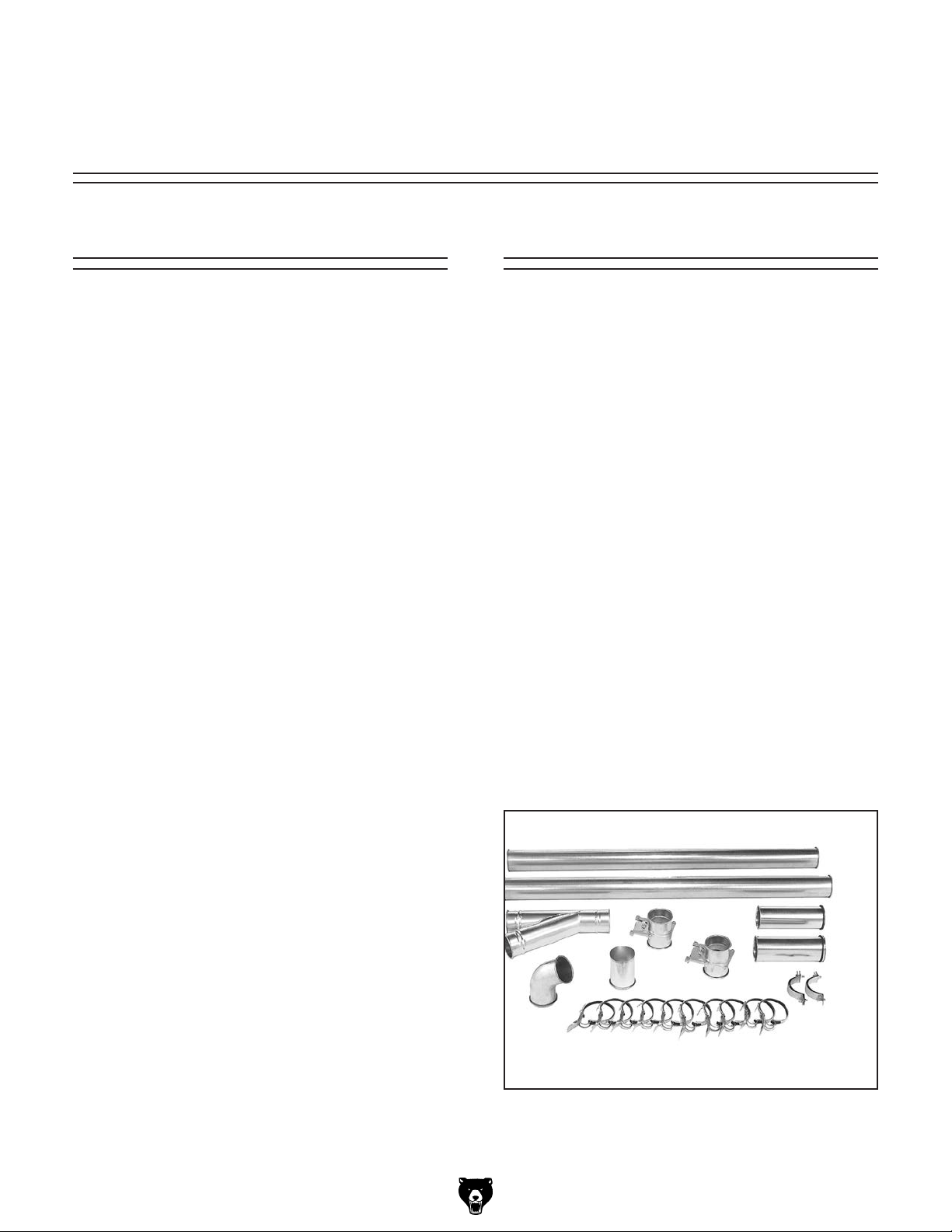
Metal Duct
Advantages of metal duct (Figure 20) is its
conductivity and that it does not contribute to
static electrical charge build-up. However, static
charges are still produced when dust particles
strike other dust particles as they move through
the duct. Since metal duct is a conductor, it can
be grounded quite easily to dissipate any static
electrical charges.
A 4-port inlet is included with the Model G0671/
G0672 and a 5-port inlet is included with the
Model G0673 for quick and economical dust collection setup. However, depending upon your
system design using this feature, bags may fill at
different rates requiring you to empty some bags
more often than others.
Whatever system you choose, always make sure
there are no open flames (including pilot lights) in
the same room as the dust collector; otherwise
you risk an explosion if dust is dispersed into the
air.
-26-
Figure 20. Examples of metal pipe and
components.
Model G0671/G0672/G0673 (Mfg. Since 1/13
Page 29

There are quite a number of options when it
comes to metal duct, but metal duct that is specially manufactured for dust collection is the best
choice. When selecting your metal duct, choose
high quality metal duct with smooth welded internal seams that will minimize airflow resistance.
This type of duct usually connects to other ducts
or elbows with a simple, self-sealing clamp, is
very quick and easy to assemble, and can be
readily dismantled and re-installed. This is especially important if you ever need to change things
around in your shop or add more machines. See
the Accessories section on Page 35 for examples.
Avoid inferior metal duct that requires you to cut it
to length and snap it together. This type of duct is
time consuming to install because it requires you
to seal all the seams with silicone and screw the
components on the ends with sheet metal screws.
Another disadvantage is the rough internal seams
and crimped ends that unavoidably increase static
pressure loss.
There are also many kinds of pure plastic flexible
hose, such as non-perforated drainage type hose
and dryer vent hose. Drainage type hose, while
being economical, does not quite have the flexibility required for dust collection. The inside of the
duct is also deeply corrugated and can increase
the static pressure loss by as much as 50% over
smooth wall duct. Dryer vent hose offers greater
flexibility, but is non-resistant to abrasion and
tends to collapse in a negative pressure system.
We DO NOT recommend using dryer vent hose in
your dust collection system.
If using flex-hose, choose one of the many types
designed specifically for the movement of solid
particles, i.e. dust, grains and plastics. However,
the cost of specifically designed flexible duct can
vary greatly. Grizzly offers polyethylene hose,
which is well suited for the removal of particulate
matter, especially sawdust, since it is durable and
completely flexible. Polyethylene is also very economical and available in a wide variety of diameters and lengths for most applications.
Flexible Duct
Flexible hose is generally used for short runs,
small shops and at rigid duct-to-tool connections.
There are many different types of flex hose on
the market today. These are manufactured from
materials such as polyethylene, PVC, cloth hose
dipped in rubber and even metal, including steel
and aluminum.
The superior choice for flexible ducting is metal
flex hose that is designed to be flexible and as
smooth as possible to reduce static pressure loss.
Plastic Duct
The popularity of plastic duct is due to the fact
that it is economical and readily available. It is
also simple to assemble and easily sealed against
air loss. The primary disadvantage of plastic duct
for dust collection is the inherent danger of static
electrical build-up.
Figure 21. Example of flexible metal duct.
Model G0671/G0672/G0673 (Mfg. Since 1/13
Figure 22. Example of plastic duct and
components.
-27-
Page 30

System Design
Step 1. Decide Who Will Design
For most small-to-medium sized shops, you can
design and build the dust collection system yourself without hiring engineers or consultants. We
have included some basic information here to get
you started on a dust collection system design.
If you have a large shop or must design a complicated system, then we recommend that you
perform additional research beyond this manual,
or seek help from an expert.
Step 2. Sketch Your Shop Layout
Planning is the most important step when designing a successful dust collection system.
Before you begin to draw your necessary layout
sketch, we recommend that you visit our FREE
Workshop Planner available on our website at
www.grizzly.com.
Our Workshop Planner will allow you to quickly
and easily draw and print a basic shop layout.
Don't worry, non-Grizzly brand machines can be
substituted with Grizzly machines for layout purposes. Note: After you're finished, make sure to
save your layout for later modification.
Step 3. Sketch a Basic Duct Layout
For the next step, sketch how your machines will
connect to the dust collector. Consider these general guidelines for planning an efficient system:
1. Machines that produce the most sawdust
should be placed nearest to the dust collector
(i.e. planers and sanders).
2. Ideally, you should design the duct system
to have the shortest possible main line and
secondary branch ducts. See Figures 24 &
25 for ideas of good duct layouts vs bad duct
layouts.
Branch
Line Ducts
Main
Line Duct
Figure 24. Good duct layout.
GOOD
Your sketch only needs the basic details of the
shop layout, similar to Figure 23, including all
your current/planned machines and your planned
placement of the dust collector.
Dust Collector
Figure 23. Initial sketch of shop layout.
-28-
BAD
Figure 25. Bad duct layout.
Model G0671/G0672/G0673 (Mfg. Since 1/13
Page 31

3. Directional changes should be kept to a mini-
mum. The more directional change fittings
you use directly increases the overall resistance to airflow.
If your machine does not have a built in dust port,
use Figure 27 to determine the size of dust port
to install on your machine.
4. Gradual directional changes are more effi-
cient than sudden directional changes (i.e.
use the largest corner radius possible when
changing hose or pipe direction).
5. Each branch line should have a blast gate
immediately after the branch to control suction from one machine to another.
6. The simpler the system, the more efficient
and less costly it will be.
Step 4. Determine Required CFM of
Each Machine
Since each machine produces a different amount
of sawdust, the requirements for the minimum
amount of CFM needed to move that sawdust is
unique to the machine (for example, a planer produces more sawdust than a table saw). Knowing
this required CFM is important in gauging which
size of duct to use.
Figure 26 will give you a close estimation of the
airflow your machine requires. Machines that
generate the most sawdust should be placed near
the dust collector. If the machine has multiple
dust ports, the total CFM required is the sum of
all ports.
Machine Average Dust Port Size
Table Saw ...................................................... 4"
Miter/Radial-Arm Saw ....................................2"
Jointer (6" and smaller) .................................4"
Jointer (8"-12") ............................................... 5"
Thickness Planer (13" and smaller) ...............4"
Thickness Planer (14"-20") ............................ 6"
Shaper ........................................................... 4"
Router (mounted to table) .............................. 2"
Bandsaw ........................................................ 4"
Lathe .............................................................. 4"
Disc Sander (12" and smaller) .......................2"
Disc Sander (13-18") ...................................... 4"
Belt Sander (6" and smaller) .........................2"
Belt Sander (7"-9") ........................................3"
Edge Sander (6" x 80" and smaller) ..............4"
Edge Sander (6" x 80" and larger) ................5"
Drum Sander (24" and smaller) ............... 2 x 4"
Drum Sander (24" and larger) ................. 4 x 4"
Widebelt Sander (18" and smaller) ................5"
Widebelt Sander (24"–37" single head) .. 2 x 6"
Widebelt Sander (24"_51" double head) .5 x 4"
Figure 27. Dust port size and quantity per
average machine.
Write the required CFM for each machine on your
sketch, as shown in Figure 28.
Machine
Dust Port Size
Approximate
Required CFM
2" 98
2.5" 150
3" 220
4" 395
5" 614
6" 884
7" 1203
8" 1570
9" 1990
10" 2456
Figure 26. Approximate required airflow for
machines, based on dust port size.
Model G0671/G0672/G0673 (Mfg. Since 1/13
98
220
395
395
395
790
614
Figure 28. CFM requirements labeled for each
machine.
-29-
Page 32

Determining Main Line Duct Size
The general rule of thumb for a main line duct is
that the velocity of the airflow must not fall below
3500 FPM.
98
395
395
790
6“ 4“ 4“
Use the inlet size of the dust collector as a starting
point for the main line. Neck the main line down
1" for every 10' of length. This will usually keep
the air velocity above 3500 FPM and, depending
on your system, will allow you to keep multiple
branches open at one time.
For the Model G0671/G0672/G0673 this is 10".
Mark your drawing, as in Figure 29.
98
220
395
395
9“ 10“
395
790
614
4“
4“ 4“ 5“
220
9“ 10“
395
614
Figure 30. Branch line sizes labeled on sketch.
Multiple Dust Ports
If your machine has multiple dust ports, add the
total CFM given for each dust port size from
Figure 26. Refer to Figure 31 and find the CFM
that is closest to your total to determine the correct branch size. Split the branch line just before
the dust ports with matching duct sizes.
Two Machines on Same Branch Line
If both machines will be running at the same time,
add the total CFM given for each dust port size
from Figure 26.
Figure 29. Main line size labeled on sketch.
Determining Branch Line Duct Size
The general rule of thumb for a branch line duct is
that the velocity of the airflow must not fall below
4000 FPM.
For small/medium sized shops, using the dust
port size from the machine as the branch line duct
size will achieve the correct velocity in most applications. However, if the dust port on the machine
is smaller than 4", make the branch line 4" and
reduce the line right before the dust port.
Note: Systems with powerful dust collectors work
better if multiple blast gates are left open. This
also allows you to run two machines at once.
Experiment with different combinations of blast
gates open/closed to find the best results for your
system.
Write your determined branch line sizes on your
drawing, as shown in Figure 30.
If both the machines will never be run at the same
time, reference the machine with biggest dust
port to Figure 31 and add blast gates after the
Y-branch to open/close the line to each machine.
Total CFM Branch Line Size
<500 4"
600 5"
700 5"
800 6"
1000 6"
1200 7"
1400 8"
1600 8"
Figure 31. Branch line sizing chart by total CFM
(for use when multiple machines share line).
-30-
Model G0671/G0672/G0673 (Mfg. Since 1/13
Page 33

Calculating Duct Resistance
Adding duct work, elbows, branches and any
other components to a duct line increases airflow
resistance (static pressure loss). This resistance
can be minimized by using rigid (smooth) pipe and
gradual curves, as opposed to flexible pipe and
90˚ elbows.
To help you think about this resistance, imagine
riding a bicycle in a tunnel that is an exact replica
of your duct work. If the inside of the tunnel is very
bumpy (flexible pipe) and has many sharp turns
(90˚ elbows), it will take a lot more effort for you to
travel from one end to the other than if your path
is smooth and straight.
The purpose of calculating this resistance is to
determine if it is low enough from the machine to
the dust collector to meet the given requirement
for the machine. Use the charts in Figure 32 to
calculate the resistance of duct work.
Duct
Dia.
2" 0.091 0.122 0.35 0.453
2.5" 0.08 0.107 0.306 0.397
3" 0.071 0.094 0.271 0.352
4" 0.057 0.075 0.215 0.28
5" 0.046 0.059 0.172 0.225
6" 0.037 0.047 0.136 0.18
7" 0.029 0.036 0.106 0.141
8" 0.023 0.027 0.08 0.108
9" 0.017 0.019 0.057 0.079
Approximate
Static Pressure
Loss Per Foot of
Rigid Pipe
Main
Lines
at 3500
FPM
Branch
Lines
at 4000
FPM
Approximate
Static Pressure
Loss Per Foot
of Flex Pipe
Main
Lines
at 3500
FPM
Branch
Lines
at 4000
FPM
In most small/medium shops it is only necessary
to calculate FPM for the line (from the dust collector to the machine) with the longest duct length or
the most fittings (operating under the assumption
that if the line with the highest resistance works,
the others will be fine).
The line with the longest duct length and most fittings in our system sketch (see Figure 30) is the
one connected to the router table, which draws
220 CFM.
To calculate the static pressure loss of any
given line in the system, follow these steps:
1. Make a list of each size duct in the line,
including the length, and multiply those numbers by the static pressure loss value given in
Figure 32.
2. List each type of elbow or branch and multiply
the quantity (if more than one) by the static
pressure loss given in Figure 32.
3. Add the additional factors from Figure 33 to
your list.
Additional Factors Static Pressure Loss
Seasoned (well used)
1
Dust Collection Filter
Entry Loss at Large
2
Machine Hood
Figure 33. Additional factors affecting static
pressure loss.
Fitting
Dia.
3" 0.47 0.235 0.282 0.188
4" 0.45 0.225 0.375 0.225
5" 0.531 0.266 0.354 0.236
6" 0.564 0.282 0.329 0.235
7" 0.468 0.234 0.324 0.216
8" 0.405 0.203 0.297 0.189
90˚
Elbow
45˚
Elbow
45˚
Wye(Y)
90˚
Wye(Y)
Figure 32. Static pressure loss charts.
Model G0671/G0672/G0673 (Mfg. Since 1/13
-31-
Page 34

model G0671
4 HP dUST ColleCToR
Customer Service #: (570) 546-9663 • To Order Call: (800) 523-4777 • Fax #: (800) 438-5901
mACHINe dATA
SHeeT
1011/8"
475/
8
"
4
"
4
"
Ø23
5
/8"
Ø23
5
/8"
6
5
/8"
1011/8"
471/4"
471/4"
Ø235/8"
Ø235/8"
6 5/8"
13.0 14.0
4. Total your list, as shown in the example in
Figure 34, to come up with your overall static
pressure loss number for that line.
Note: Always account for a seasoned filter,
so you don't end up with a system that only
works right when the filter is clean.
Main Line
6" Rigid Pipe (0.037) at 20' ................ 0.740
Branch Line
4" Rigid Pipe (0.075) at 10' ................ 0.750
4" Flex Pipe (0.28) at 5' ........................ 1.400
Elbows/Branches
6" 45˚ Y-Branch ................................ 0.329
4" 45˚ Elbow ........................................ 0.225
Additional Factors
Seasoned Filter ................................ 1.000
4000
Performance Curve
3750
3500
3250
3000
2750
2500
Closest
2250
2000
1750
1500
1250
1000
750
500
250
CFM
Figure 35. CFM for static pressure loss of line
CFM
(3550)
4.4 SP Loss
0
0 1.0 2.0 3.0 4.0 5.0 6.0 7.0 8.0 9.0 10.0 11.0 12.0
STATIC PRESSURE (Inch/H2O)
connected to G0671 dust collector & router.
Total Static Pressure Loss ................ 4.444
Figure 34. Example list for totaling SP loss.
—If the CFM for your static pressure loss
is above the requirement of the machine
connected to the end of that branch line,
Note: When calculating static pressure loss to
determine if multiple lines can be left open at the
same time, only include the main line numbers
once.
then dust collection will most likely be
successful. Congratulations! You've just
designed your own dust system. Refer to
the Accessories section on Page 35 to
start buying the components necessary to
5. Compare the total static pressure loss for
that line to the closest CFM given in the
Performance Curve section on the Machine
Data Sheet (located toward the front of this
manual).
make your system a reality.
—If the CFM for your static pressure loss is
below the requirement of the machine, then
that line will not effectively collect the dust.
You must then modify some of the factors
Example: go to the Model G0671 Data Sheet
Performance Curve section (see Page 4) or
see Figure 35 and find 4.4 on the Pressure
axis, then go up the CFM axis to the closest
value—approximately 3550 CFM, as shown
in Figure 35.
in that line to reduce the static pressure
loss. Some of the ways to do this include:
1) Installing larger duct, 2) reducing amount
of flexible duct used, 3) increasing machine
dust port size, 4) moving machine closer to
dust collector to eliminate duct length, and
5) reducing 90˚ elbows or replacing them
The 3550 CFM (Figure 35) for the static pres-
with 45˚ elbows
sure loss of the line connected to the router is
well above the 220 CFM requirement of that
machine.
-32-
Model G0671/G0672/G0673 (Mfg. Since 1/13
Page 35

System Grounding
Since plastic hose is abundant, relatively inexpensive, easily assembled and air tight, it is a
very popular material for conveying dust from
woodworking machines to the dust collector. We
recommend using flexible hose (flex-hose) to connect the woodworking machine to the dust collection system. However, plastic flex-hose and plastic
duct are insulators, and dust particles moving
against the walls of the plastic duct create static
electrical build up. This charge will build until it
discharges to a ground. If a grounding medium
is not available to prevent static electrical build
up, the electrical charge will arc to the nearest
grounded source. This electrical discharge may
cause an explosion and subsequent fire inside
the system.
Ensure that the entire system is grounded. If using
plastic blast gates to direct air flow, the grounding
wire must be jumped (Figure 36) around the
blast gate without interruption to the grounding
system.
Plastic
Blast
Gate
Copper
Ground
Wire
Metal Duct
To protect against static electrical build up inside
a non-conducting duct, a bare copper wire should
be placed inside the duct along its length and
grounded to the dust collector. You must also
confirm that the dust collector is continuously
grounded through the electrical circuit to the electric service panel.
If you connect the dust collector to more than one
machine by way of a non-conducting branching
duct system and blast gates, the system must still
be grounded as mentioned above. We recommend inserting a continuous bare copper ground
wire inside the entire duct system and attaching
the wire to each grounded woodworking machine
and dust collector.
Be sure that you extend the bare copper wire
down all branches of the system. Do not forget
to connect the wires to each other with wire nuts
when two branches meet at a “Y” or “T” connection.
Figure 36. Ground jumper wire when using
plastic blast gates and metal duct.
External Ground
Wire
Internal
Ground
Wire
Flex-Hose
Figure 37. Flex-hose grounded to machine.
We also recommend wrapping the outside of all
plastic ducts with bare copper wire to ground the
outside of the system against static electrical build
up. Wire connections at Y’s and T’s should be
made with wire nuts.
Ground Screw
Always guard against
static electrical build up
by grounding all dust
collection lines.
Model G0671/G0672/G0673 (Mfg. Since 1/13
Attach the bare ground wire to each stationary
woodworking machine and attach to the dust collector frame with a ground screw, as shown in
Figure 37. Ensure that each machine is continuously grounded to the grounding terminal in your
electric service panel.
-33-
Page 36

SECTION 5: OPERATIONS
To reduce the risk of
serious injury when using
this machine, read and
understand this entire
manual before beginning
any operations.
Damage to your eyes, lungs, and ears could
result from using this machine without
proper protective gear. Always wear safety
glasses, a respirator, and hearing protection
when operating this machine.
Basic Controls
This section covers the basic controls used during
routine operations:
ON Button: Starts the motor.
OFF Button: Stops the motor.
ON
Loose hair, clothing, or
jewelry could get caught
in machinery and cause
serious personal injury.
Keep these items away
from moving parts at all
times to reduce this risk.
NOTICE
If you have never used this type of machine
or equipment before, WE STRONGLY RECOMMEND that you read books, trade magazines, or get formal training before beginning any projects. Regardless of the content in this section, Grizzly Industrial will
not be held liable for accidents caused by
lack of training.
OFF
Figure 38. ON/OFF button locations.
General
Operating your Model G0671/G0672/G0673 is
simple and straightforward. Blast gates located
at each of the woodworking machines control the
airflow from the woodworking machine to the dust
collector. If a machine is not being used, keep
the blast gate closed to maintain higher levels of
efficiency throughout the system.
DO NOT use the dust collector for any
other purpose besides collecting dust from
connected woodworking machines. A dust
collector should NEVER be used as a shop
vacuum. For safest use, wear a respirator
and use an air cleaner in addition to the
dust collector.
-34-
Model G0671/G0672/G0673 (Mfg. Since 1/13
Page 37

ACCESSORIES
SECTION 6: ACCESSORIES
H5293—4" Metal Duct Starter Kit
H5295—5" Metal Duct Starter Kit
H5297—6" Metal Duct Starter Kit
Save over 20% with this great starter kit. Includes:
(2) machine adapters, (10) pipe clamps, (3) 5'
straight pipes, (1) branch, (3) pipe hangers, (1)
end cap, (3) adjustable nipples, (1) 90˚ elbow, and
(1) 60˚ elbow.
G6162—4" x 5' Straight Metal Pipe
G7346—5" x 5' Straight Metal Pipe
G7364—6" x 5' Straight Metal Pipe
H5227—7" x 5' Straight Metal Pipe
H5237—8" x 5' Straight Metal Pipe
H5252—9" x 5' Straight Metal Pipe
These laser welded straight pipes ensure a super
smooth internal seam. Ends easily clamp together
for a sealed fit without screws or silicone.
Figure 39. Metal Duct Starter Kit.
H5294—4" Metal Duct Machine Addition Kit
H5296—5" Metal Duct Machine Addition Kit
H5298—6" Metal Duct Machine Addition Kit
Save over 20% with this great machine addition
kit. Includes: (2) blast gates, (1) machine adapter,
(10) pipe clamps, (2) pipe hangers, (2) 5' straight
pipes, (2) adjustable nipples, (1) branch, and (1)
60˚ elbow.
Figure 41. Straight Metal Pipe.
H7216—5" x 5' Rigid Metal Flex Hose
H7217—6" x 5' Rigid Metal Flex Hose
H7218—7" x 5' Rigid Metal Flex Hose
H7219—8" x 5' Rigid Metal Flex Hose
H7220—9" x 5' Rigid Metal Flex Hose
This flex hose provides just enough flexibility to
make difficult connections while still keeping the
inside wall as smooth as possible to minimize
static pressure loss.
Figure 40. Metal Duct Machine Addition Kit.
Model G0671/G0672/G0673 (Mfg. Since 1/13
Figure 42. Rigid Metal Flex Hose.
-35-
Page 38

Metal Elbows
These industrial metal elbows are available from
4"–8" with 90˚, 60˚, 45˚, or 30˚ curves. Also, available with a 90˚ long radius curve. Call (800) 5234777 or visit www.grizzly.com for more information and pricing.
Metal Branches
We carry many different branches, all designed
to minimize airflow resistance.
90°
30°
45°
Figure 43. Metal elbow examples.
G6177—4" Metal Blast Gate
G7340—5" Metal Blast Gate
G7358—6" Metal Blast Gate
H5234—7" Metal Blast Gate
H5249—8" Metal Blast Gate
H5259—9" Metal Blast Gate
90° Long Radius
60°
Figure 45. Metal Branches.
Reducers & Adapters
We carry a multitude of reducers and elbows to
cover most applications from 4" through 9".
Figure 46. Metal Reducers & Adapters.
Figure 44. Metal Blast Gate.
G8296—Mag Switch 3-Phase 440V for Model
G0673 Conversion
-36-
G7979—Phase Converter for Model G0673
Add 3-phase multi-motor capability to your singlephase electrical supply! Operate single or multiple
motors, transformers, and resistance loads at
100% power and 95% efficiency while saving big
dollars at cheaply-metered single-phase electrical
rates.
1
H2443—9
⁄2" x 6" Universal Adapter
Seven step adapter provides a multitude of dust
collection reducing options.
Figure 47. H2443 Universal Adapter.
Model G0671/G0672/G0673 (Mfg. Since 1/13
Page 39

SECTION 7: MAINTENANCE
Disconnect power to the
machine when performing any maintenance,
assembly or adjustments.
Failure to do this may
result in serious personal
injury.
Keep loose clothing
rolled up and out of the
way of machinery and
keep hair pulled back.
Schedule
For optimum performance from your machine,
follow this maintenance schedule and refer to any
specific instructions given in this section.
Daily Check:
• Dust collector is completely powered down at
the end of use.
• Loose mounting bolts.
• Worn switch or wires.
• Any other condition that would hamper the
safe operation of this machine.
• Empty the lower collection bags before they
become completely full.
Bag Cleaning
All dust collectors disperse fine dust which may
cause allergic reactions
or respiratory problems.
Always wear a respirator
when operating your dust
collector.
Empty the lower collection bags on a regular
basis to maintain dust collection efficiency.
Always wear the appropriate respirator or dust
mask and safety glasses when emptying the collection bags. Small dust particles can escape the
bags during emptying, causing them to become
airborne and easily inhaled. This microscopic airborne dust is extremely unhealthy to breathe and
can cause serious health problems.
While the Model G0671/G0672/G0673 excels at
collecting the majority of wood dust produced
by your machines, we always recommend the
supplemental aid of a shop air filter. Air filters are
designed to collect the smaller airborne dust particles that a dust collector bags cannot trap.
Lubrication
Since all bearings are shielded and permanently
lubricated, simply leave them alone until they
need to be replaced. Do not lubricate them.
Model G0671/G0672/G0673 (Mfg. Since 1/13
-37-
Page 40

SECTION 8: SERVICE
Review the troubleshooting and procedures in this section to fix or adjust your machine if a problem develops. If you need replacement parts or you are unsure of your repair skills, then feel free to call our Technical
Support at (570) 546-9663.
Troubleshooting
Motor & Electrical
Symptom Possible Cause Possible Solution
Machine does not
start or a breaker
trips.
Machine stalls or is
underpowered.
Machine has
vibration or noisy
operation.
1. Plug/receptacle is at fault or wired
incorrectly.
2. Motor connection wired incorrectly.
3. Thermal overload relay has tripped.
4. Contactor not getting energized/has burnt
contacts.
5. Power supply is at fault/switched OFF.
6. Motor ON button or ON/OFF switch is at
fault.
7. Centrifugal switch is at fault.
8. Wiring is open/has high resistance.
9. Motor is at fault.
1. Motor connection is wired incorrectly.
2. Plug/receptacle is at fault.
3. Motor bearings are at fault.
4. Motor has overheated.
5. Contactor not getting energized or has
poor contacts.
6. Motor is at fault.
7. Centrifugal switch is at fault.
1. Motor or component is loose.
2. Motor fan is rubbing on fan cover.
3. Motor mount loose/broken.
4. Motor bearings are at fault.
5. Centrifugal switch.
1. Test for good contacts; correct the wiring.
2. Correct motor wiring connections.
3. Turn cut-out dial to increase working amps and
push the reset pin. Replace if tripped multiple
times (weak relay).
4. Test for power on all legs and contactor operation.
Replace unit if faulty.
5. Ensure hot lines have correct voltage on all legs
and main power supply is switched ON.
6. Replace faulty ON button or ON/OFF switch.
7. Adjust/replace the centrifugal switch if available.
8. Check for broken wires or disconnected/corroded
connections, and repair/replace as necessary.
9. Test/repair/replace.
1. Correct motor wiring connections.
2. Test for good contacts; correct the wiring.
3. Test by rotating shaft; rotational grinding/loose
shaft requires bearing replacement.
4. Clean off motor, let cool, and reduce workload.
5. Test for power on all legs and contactor operation.
Replace if faulty.
6. Test/repair/replace.
7. Adjust/replace centrifugal switch if available.
1. Inspect/replace stripped or damaged bolts/nuts,
and re-tighten with thread locking fluid.
2. Replace dented fan cover; replace loose/damaged
fan.
3. Tighten/replace.
4. Test by rotating shaft; rotational grinding/loose
shaft requires bearing replacement.
5. Replace.
-38-
Model G0671/G0672/G0673 (Mfg. Since 1/13
Page 41

Dust Collection Operation
SYMPTOM POSSIBLE CAUSE CORRECTIVE ACTION
Loud, repetitious noise, or
excessive vibration coming
from dust collector.
Dust collector does not
adequately collect dust or
chips; poor performance.
Sawdust being blown
into the air from the dust
collector.
1. Dust collector is not on a flat
surface and wobbles.
2. Impeller fan is damaged and
unbalanced.
3. The motor mounting is loose.
4. Impeller is loose on the motor
shaft.
5. Motor fan cover is dented, causing
the motor fan to hit the cover while
spinning.
1. Dust collection bag is full/filter bag
is dir t y.
2. There is a restriction in the duct
line.
3. The dust collector is too far away
from the point of suction, or there
are too many sharp bends in the
ducting.
4. The lumber is wet and not flowing
through the dust lines smoothly.
5. There is a leak in the ducting, or a
series of small leaks, or too many
open ports.
6. There are not enough open branch
lines at one time, thereby causing
a velocity drop in the main line.
7. The ducting and ports are
incorrectly sized.
8. The machine dust collection
design is inadequate.
9. The dust collector is too small for
the dust collection system.
1. Bag clamps, dust collection
bag, or filter bag is not properly
secured.
1. Stabilize the dust collector.
2. Unplug dust collector, and inspect the impeller for
dents, bends, loose fins. Replace impeller if any
damage is found.
3. Make sure all fasteners on the dust collector are
tight.
4. Replace the motor and impeller as a set if the
motor shaft and the impeller hub is damaged.
5. Replace motor fan cover.
1. Empty collection bag/clean or replace filter bag.
2. Remove dust line from dust collector inlet and
unblock the restriction in the duct line. A plumbing
snake may be necessary.
3. Relocate the dust collector closer to the point of
suction, and rework ducting without sharp bends.
Refer to Designing the System, beginning on
Page 26.
4. Process lumber with less than 20% moisture
content.
5. Rework the ducting to eliminate all leaks. Close
dust ports for lines not being used. Refer to
Designing the System on Page 26 for more
solutions.
6. Open 1 or 2 more blast gates to different branch
lines to allow the velocity in the main line to
increase.
7. Reinstall correctly sized ducts and fittings. Refer
to Designing the System on Page 26 for more
solutions.
8. Use a dust collection nozzle on a stand.
9. Install a larger dust collector to power your dust
collection system.
1. Reclamp the dust collection bag and air filter bag,
making sure bag clamps are tight and completely
over the bags.
Model G0671/G0672/G0673 (Mfg. Since 1/13
-39-
Page 42

Wiring
SECTION 9: WIRING
These pages are current at the time of printing. However, in the spirit of improvement, we may make changes to the electrical systems of future machines. Study this section carefully. If there are differences between
your machine and what is shown in this section, call Technical Support at (570) 546-9663 for assistance
BEFORE making any changes to the wiring on your machine.
Wiring Safety Instructions
1. SHOCK HAZARD. Working on wiring that
is connected to a power source is extremely
dangerous. Touching electrified parts will
result in personal injury including but not limited to severe burns, electrocution, or death.
Disconnect the power from the machine
before servicing electrical components!
2. QUALIFIED ELECTRICIAN. Due to the
inherent hazards of electricity, only a qualified electrician should perform wiring tasks
on this machine. If you are not a qualified electrician, get help from one before
attempting any kind of wiring job.
3. WIRE CONNECTIONS. All connections
must be tight to prevent wires from loosening during machine operation. Double-check
all wires disconnected or connected during
any wiring task to ensure tight connections.
4. WIRE/COMPONENT DAMAGE. Damaged
wires or components increase the risk of
serious personal injury, fire, or machine
damage. If you notice that any wires or
components are damaged while performing
a wiring task, replace those wires or components before completing the task.
5. MODIFICATIONS. Using aftermarket parts or
modifying the wiring beyond what is shown
in the diagram may lead to unpredictable
results, including serious injury or fire.
6. MOTOR WIRING. The motor wiring shown
in these diagrams is current at the time of
printing, but it may not match your machine.
Always use the wiring diagram inside the
motor junction box.
7. CAPACITORS. Some capacitors store an
electrical charge for up to five minutes after
being disconnected from the power source.
To avoid being shocked, wait at least this
long before working on capacitors.
8. CIRCUIT REQUIREMENTS. You MUST fol-
low the requirements on Page 16 when connecting your machine to a power source.
9. EXPERIENCING DIFFICULTIES. If you are
experiencing difficulties understanding the
information included in this section, contact
our Technical Support at (570) 546-9663.
The photos and diagrams
included in this section are
best viewed in color. You
can view these pages in
color at www.grizzly.com.
-40-
Model G0671/G0672/G0673 (Mfg. Since 1/13
Page 43

G0671 Wiring Diagram
COLOR KEY
Bk
Gn
Rd
Wt
View this page in color at
www.grizzly.com.
BLACK
GREEN
RED
WHITE
A
Wt
Bk
L1/1 L3/5
T1/2 T3/6
1/2
Wt
Bk
Gn
Wt
Bk
L2/3
T2/4
3/4
Bk
Gn
NO13
NC15
SDE
NC16
NO14
Gn
B
AMP
RESET
OFF
5/6
Bk
22
34
28
96
98
Bk
Bk
95
Bk
Gn
Wt
Gn
Wt
Bk
Ground
Capacitor
300VAC
MOTOR at 220V
SINGLE PHASE
Model G0671/G0672/G0673 (Mfg. Since 1/13
Bk
Rd Rd
Run
50MFD
Bk
Rd Rd
Start
Capacitor
600MFD
250VAC
Gn
Wt
Bk
Hot
Ground
Locking Shut-Off Switch
(As Recommended)
READ ELECTRICAL SAFETY
ON PAGE 40!
-41-
Page 44

G0672 Wiring Diagram
COLOR KEY
Bk
Gn
Rd
Wt
View this page in color at
www.grizzly.com.
BLACK
GREEN
RED
WHITE
A
Wt
Bk
L1/1 L3/5
T1/2 T3/6
1/2
Wt
Bk
Gn
Wt
Bk
L2/3
T2/4
3/4
Bk
Gn
NO13
NC15
SDE
NC16
NO14
Gn
B
SDE RA-30
AMP
RESET
5/6
42
96
Bk
Bk
Set
to
28
37A
35
98
Bk
95
Bk
Gn
Wt
-42-
Gn
Wt
Bk
Start
Capacitor
800MFD
250VAC
Ground
MOTOR at 220V
SINGLE PHASE
READ ELECTRICAL SAFETY
ON PAGE 40!
Bk
Rd Rd
Run
Capacitor
50MFD
250VAC
Bk
Rd Rd
Run
Capacitor
50MFD
250VAC
Gn
Wt
Bk
Hot
Ground
Locking Shut-Off Switch
(As Recommended)
Model G0671/G0672/G0673 (Mfg. Since 1/13
Page 45
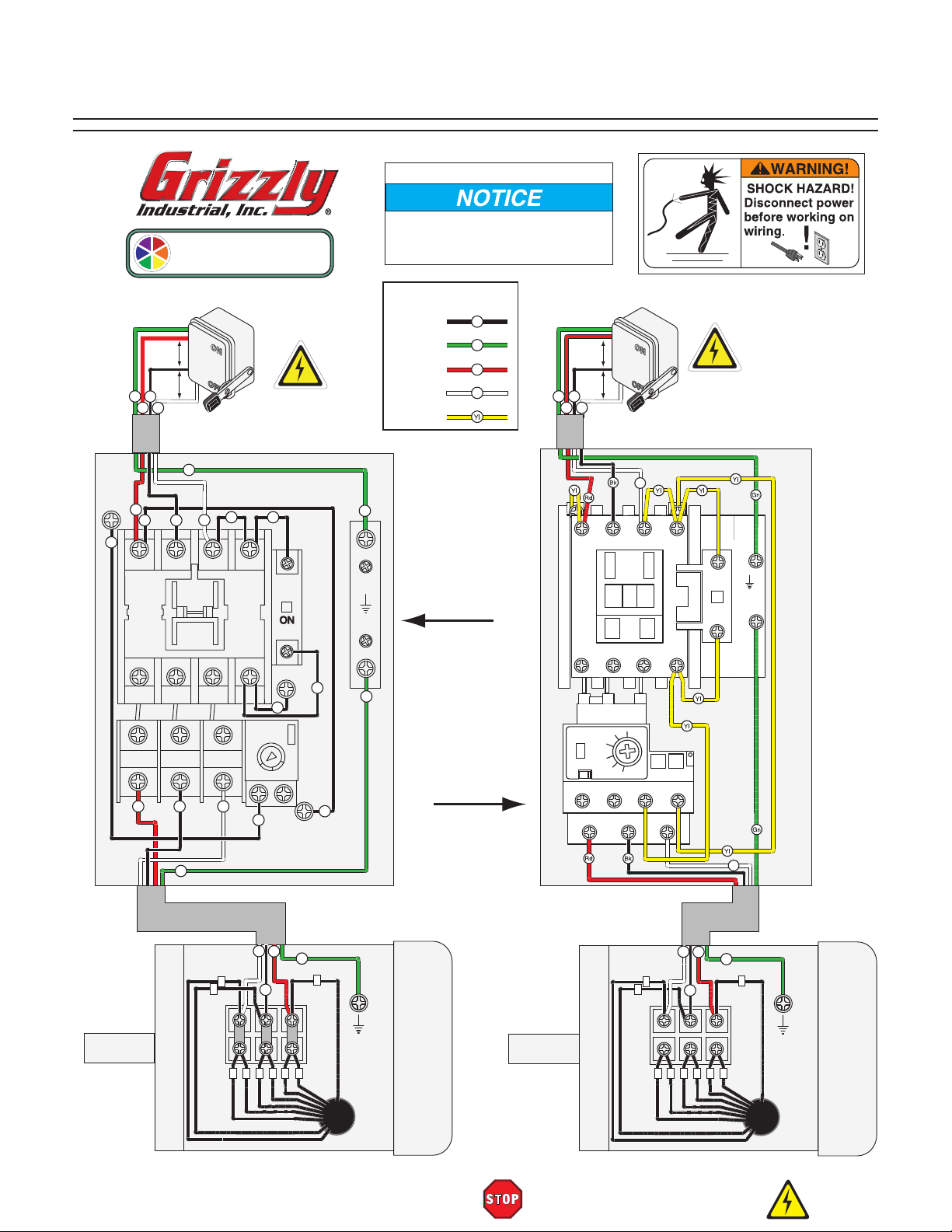
G0673 Wiring Diagram
View this page in color at
www.grizzly.com.
MOTOR DIRECTION
If motor rotates in opposite direction, swap any two power source
wires at the incoming terminals.
Ground
Hot
Hot
Gn
Bk
Rd
Wt
Hot
Gn
A
Rd
Bk
Bk
Bk
L1/1 L3/5 7L2/3
T1/2 T3/6 8
T2/4
1/2
3/4
Rd
Bk
3-PHASE
220 VAC
See Figure 51
Bk Bk
Wt
Bk
AMP
5/6
34
28
96
Wt
Bk
COLOR KEY
BLACK
GREEN
RED
WHITE
Bk
Gn
Rd
Wt
YELLOW
Gn
220V
MAGNETIC
SWITCH
ASSEMBLY
B
Bk
Gn
440V
Ground
Hot
Bk
Gn
Rd
Hot
Wt
1L1
TECO
CN16
2T1
Hot
3L2 5L3
4T2
3-PHASE
440 VAC
DISCONNECT
SWITCH
(as recommended
Wt
13
NO
NO
53
Ground
ON
54
NO
14
NO
6T3
)
MAGNETIC
RESET
OFF
22
98
Bk
95
SWITCH
ASSEMBLY
(G8296)
TRIP IND.
TEST
97 NO
2T1
98 NO
4T2
95 NC
M
R
O
A
RESET
OFF
96 NC
6T3
Gn
See Figure 52
MOTOR
at
220V
3-PHASE
Wt
Rd
Gn
3
2
Bk
1
Ground
4 6 78
5 9
Model G0671/G0672/G0673 (Mfg. Since 1/13
MOTOR
Wt
Rd
at
440V
3-PHASE
3
2
Bk
5 46 79 8
READ ELECTRICAL SAFETY
ON PAGE 40!
Wt
Gn
1
Ground
-43-
Page 46

SECTION 10: PARTS
G0671 Parts Breakdown
16
16
1-2
1-3
1-4
1-5
1-6
1-7
1-1
20
19
18
19
38
28
29
30
17
15
40
9
5
4
1
6
10
17
11
21
14
26
39
22
20
13
19
17
7
8
15
17
12
40
30
31
33
32
2
34
35
24
23
36
41
3
22
21
27
18
28
29
19
38
33-2
33-4
-44-
1-8
27
26
33-5
25
37
33-1
33-3
Model G0671/G0672/G0673 (Mfg. Since 1/13
Page 47

G0671 Parts List
REF PART # DESCRIPTION REF PART # DESCRIPTION
1 P0671001 MOTOR 4HP, 220V, 1 PH 20 P0671020 FILTER BAG 30 MICRON 23-5/8" X 47-1/4"
1-1 P0671001-1 FAN COVER 21 P0671021 RIGHT LEG
1-2 P0671001-2 FAN 22 P0671022 LEFT LEG
1-3 P0671001-3 S CAPACITOR COVER 23 PB23 HEX BOLT 5/16-18 X 2-1/2
1-4 P0671001-4 S CAPACITOR 600M 250V X 1-3/4 X 3-7/8 24 PN02 HEX NUT 5/16-18
1-5 P0671001-5 R CAPACITOR COVER 25 PB09 HEX BOLT 5/16-18 X 1/2
1-6 P0671001-6 R CAPACITOR 50M 300V X 1-3/4 X 2-3/4 26 P0671026 F/R LEG BRACE
1-7 P0671001-7 JUNCTION BOX 27 P0671027 L/R LEG BRACE
1-8 P0671001-8 CENTRIFUGAL SWITCH 28 PB03 HEX BOLT 5/16-18 X 1
2 PN08 HEX NUT 3/8-16 29 PW07 FLAT WASHER 5/16
3 PLW04 LOCK WASHER 3/8 30 PN02 HEX NUT 5/16-18
4 PK143M KEY 6 X 6 X 25 31 P0671031 MAGNETIC SWITCH PLATE
5 P0671005 MOTOR GASKET 32 PS01 PHLP HD SCR 10-24 X 1/2
6 PB07 HEX BOLT 5/16-18 X 3/4 33 P0671033 MAGNETIC SWITCH
7 P0671007 INLET COVER 33-1 P0671033-1 MAG SWITCH BACK COVER
8 P0671008 IMPELLER 14-1/2" 33-2 P0671033-2 CONTACTOR SDE MP-15 220V
9 PB34 HEX BOLT 3/8-16 X 1/2 33-3 P0671033-3 OL RELAY SDE RA-30 21-35
10 PSB02M CAP SCREW M6-1 X 20 33-4 P0671033-4 MAG SWITCH FRONT COVER
11 PW03M FLAT WASHER 6MM 33-5 P0671033-5 PLASTIC COVER SCREW 11/32-16 X 3/4
12 P0671012 COLLECTOR HOUSING 34 P0671034 STRAIN RELIEF
13 PS06 PHLP HD SCR 10-24 X 3/8 35 P0671035 MOTOR CORD 12AWG X 3C
14 P0671014 INLET ADAPTER 36 P0671036 POWER CORD 12AWG X 3C
15 P0671015 BAG HANGER LOWER SUPPORT 37 P0671037 CASTER WITH BRAKE
16 P0671016 BAG HANGER 38 P0671038 LOWER DUST BAG 23-5/8" X 47-1/4"
17 PB19 HEX BOLT 1/4-20 X 1/2 39 PB24 HEX BOLT 3/8-16 X 1-1/4
18 P0671018 COLLECTOR DRUM 40 P0671040 RUBBER GASKET
19 P0671019 BAG CLAMP 41 PW02 FLAT WASHER 3/8
Model G0671/G0672/G0673 (Mfg. Since 1/13
-45-
Page 48

G0672 Parts Breakdown
16
16
1-2
1-4
1-7
1-1
1-5
1-6
20
18
19
19
38
28
29
17
15
30
21
40
9
4
1
6
10
17
5
11
14
26
39
3
22
2
41
7
12
13
8
31
32
36
22
15
17
27
17
23
30
33V2
34
35
21
24
40
20
19
18
28
29
19
38
33-2
33-4
-46-
1-8
27
26
25
37
33-1
33-3V2
Model G0671/G0672/G0673 (Mfg. Since 1/13
33-5
Page 49

G0672 Parts List
REF PART # DESCRIPTION REF PART # DESCRIPTION
1 P0672001 MOTOR 5HP, 220V, 1 PH 21 P0671021 RIGHT LEG
1-1 P0672001-1 FAN COVER 22 P0671022 LEFT LEG
1-2 P0672001-2 FAN 23 PB23 HEX BOLT 5/16-18 X 2-1/2
1-4 P0672001-4 S CAPACITOR 800M 250V 1-3/4 X 3-3/4 24 PN02 HEX NUT 5/16-18
1-5 P0672001-5 R CAPACITOR COVER 25 PB09 HEX BOLT 5/16-18 X 1/2
1-6 P0672001-6 R CAPACITOR 50M 250V 2 X 4-3/8 26 P0671026 F/R LEG BRACE
1-7 P0672001-7 JUNCTION BOX 27 P0671027 L/R LEG BRACE
1-8 P0672001-8 CENTRIFUGAL SWITCH 28 PB03 HEX BOLT 5/16-18 X 1
2 PN08 HEX NUT 3/8-16 29 PW07 FLAT WASHER 5/16
3 PLW04 LOCK WASHER 3/8 30 PN02 HEX NUT 5/16-18
4 PK143M KEY 6 X 6 X 25 31 P0671031 MAGNETIC SWITCH PLATE
5 P0671005 MOTOR GASKET 32 PS01 PHLP HD SCR 10-24 X 1/2
6 PB07 HEX BOLT 5/16-18 X 3/4 33V2 P0671033V2 MAGNETIC SWITCH V2.01.13
7 P0671007 INLET COVER 33-1 P0671033-1 MAG SWITCH BACK COVER
8 P0672008 IMPELLER 15" 33-2 P0671033-2 CONTACTOR SDE MP-15 220V
9 PB34 HEX BOLT 3/8-16 X 1/2 33-3V2 P0672033-3V2 OL RELAY SDE RA-30 28-42A V2.01.13
10 PSB02M CAP SCREW M6-1 X 20 33-4 P0671033-4 MAG SWITCH FRONT COVER
11 PW03M FLAT WASHER 6MM 33-5 P0671033-5 PLASTIC COVER SCREW 11/32-16 X 3/4
12 P0671012 COLLECTOR HOUSING 34 P0672034 STRAIN RELIEF
13 PS06 PHLP HD SCR 10-24 X 3/8 35 P0672035 MOTOR CORD 10AWG X 3C
14 P0671014 INLET ADAPTER 36 P0672036 POWER CORD 10AWG X 3C
15 P0672015 BAG HANGER LOWER SUPPORT 37 P0671037 CASTER WITH BRAKE
16 P0672016 BAG HANGER 38 P0672038 LOWER DUST BAG 23-5/8" X 57"
17 PB19 HEX BOLT 1/4-20 X 1/2 39 PB24 HEX BOLT 3/8-16 X 1-1/4
18 P0671018 COLLECTOR DRUM 40 P0671040 RUBBER GASKET
19 P0671019 BAG CLAMP 41 PW02 FLAT WASHER 3/8
20 P0672020 FILTER BAG 2.5 MICRON 23-5/8" X 70"
Model G0671/G0672/G0673 (Mfg. Since 1/13
-47-
Page 50
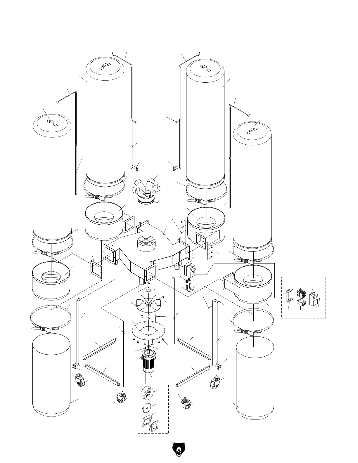
G0673 Parts Breakdown
20
16
20
15
19
16
19
18
15
17
14
17
34
17
13
15
19
27
16
18
20
16
20
15
19
18
35
25
21
40
26
24
24
26
21
29
30
31
12
9
7
4
3
11
5
2
1
1-1
1-2
1-3
33
10
8
6
26
32
22
21
24
24
28
19
21
19
23
26
25
35
18
30-1
30-2
30-3
30-4
30-5
-48-
Model G0671/G0672/G0673 (Mfg. Since 1/13
Page 51
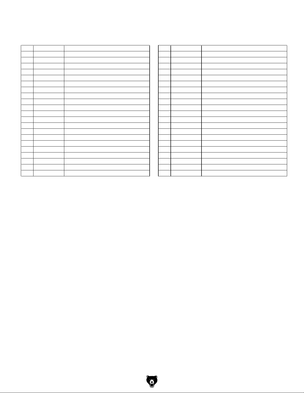
G0673 Parts List
REF PART # DESCRIPTION REF PART # DESCRIPTION
1 P0673001 MOTOR 10HP, 220V, 3 PH 20 P0672020 FILTER BAG 2.5 MICRON 23-5/8" X 70"
1-1 P0673001-1 FAN COVER 21 P0673021 LEG
1-2 P0673001-2 FAN 22 PB23 HEX BOLT 5/16-18 X 2-1/2
1-3 P0673001-3 JUNCTION BOX 23 PN02 HEX NUT 5/16-18
2 PN41 HEX NUT 1/2"-12 24 P0673024 LEG BRACE
3 PLW07 LOCK WASHER 1/2 25 PB09 HEX BOLT 5/16-18 X 1/2
4 PK149M KEY 8 X 8 X 25 26 P0671037 CASTER WITH BRAKE
5 P0673005 MOTOR GASKET 27 PB03 HEX BOLT 5/16-18 X 1
6 PB07 HEX BOLT 5/16-18 X 3/4 28 PN02 HEX NUT 5/16-18
7 P0673007 INLET COVER 29 PS01 PHLP HD SCR 10-24 X 1/2
8 P0673008 HEX BOLT 1/2 X 1-1/2 30 P0673030 MAGNETIC SWITCH
9 P0673009 IMPELLER 17" 30-1 P0673030-1 MAG SWITCH BACK COVER
10 PB16 HEX BOLT 3/8-16 X 1-1/2 30-2 P0673030-2 CONTACTOR SDE MP-30 220V 3PH
11 PW03M FLAT WASHER 6MM 30-3 P0671033-3 OL RELAY SDE RA-30 21-35
12 PSB02M CAP SCREW M6-1 X 20 30-4 P0673030-4 MAG SWITCH FRONT COVER
13 P0673013 COLLECTOR HOUSING 30-5 P0671033-5 PLASTIC COVER SCREW 11/32-16 X 3/4
14 P0673014 INLET ADAPTER 31 P0673031 STRAIN RELIEF
15 P0672015 BAG HANGER LOWER SUPPORT 32 P0673032 MOTOR CORD 10AWG X 4C
16 P0672016 BAG HANGER 33 P0673033 POWER CORD 10AWG X 4C
17 PB19 HEX BOLT 1/4-20 X 1/2 34 PS06 PHLP HD SCR 10-24 X 3/8
18 P0671018 COLLECTOR DRUM 35 P0672038 LOWER DUST BAG 23-5/8" X 57"
19 P0671019 BAG CLAMP 40 P0671040 RUBBER GASKET
Model G0671/G0672/G0673 (Mfg. Since 1/13
-49-
Page 52

Label Placement
56
55
56
54
G0671
50
G0673
53
52
51
51
G0672
50
51
56
55
54
REF PART # DESCRIPTION
50 P0671050 HANDS INLET WARNING (G0671, G0672)
51 P0671051 MACHINE ID LABEL (G0671)
51 P0672051 MACHINE ID LABEL (G0672)
51 P0673051 MACHINE ID LABEL (G0673)
52 G8588 GRIZZLY NAMEPLATE (G0671, G0672)
52 G9987 GRIZZLY NAMEPLATE (G0673)
53 PLABEL-15 EAR PROTECTION 2" X 3-5/16"H
54 PLABEL-37 GLASSES/RESPIRATOR
55 PLABEL-12A READ MANUAL-VERTICAL NS 7/05
56 PPAINT-1 GRIZZLY GREEN TOUCH-UP PAINT
53
52
55
54
53
52
Safety labels warn about machine hazards and ways to prevent injury. The owner of this machine
MUST maintain the original location and readability of the labels on the machine. If any label is
removed or becomes unreadable, REPLACE that label before using the machine again. Contact
Grizzly at (800) 523-4777 or www.grizzly.com to order new labels.
-50-
Model G0671/G0672/G0673 (Mfg. Since 1/13
Page 53

WARRANTY CARD
Name _____________________________________________________________________________
Street _____________________________________________________________________________
City _______________________ State _________________________ Zip _____________________
Phone # ____________________ Email _________________________________________________
Model # ____________________ Order # _______________________ Serial # __________________
The following information is given on a voluntary basis. It will be used for marketing purposes to help us develop
better products and services. Of course, all information is strictly confidential.
1. How did you learn about us?
____ Advertisement ____ Friend ____ Catalog
____ Card Deck ____ Website ____ Other:
2. Which of the following magazines do you subscribe to?
____ Cabinetmaker & FDM
____ Family Handyman
____ Hand Loader
____ Handy
____ Home Shop Machinist
____ Journal of Light Cont.
____ Live Steam
____ Model Airplane News
____ Old House Journal
____ Popular Mechanics
3. What is your annual household income?
____ $20,000-$29,000 ____ $30,000-$39,000 ____ $40,000-$49,000
____ $50,000-$59,000 ____ $60,000-$69,000 ____ $70,000+
CUT ALONG DOTTED LINE
4. What is your age group?
____ 20-29 ____ 30-39 ____ 40-49
____ 50-59 ____ 60-69 ____ 70+
5. How long have you been a woodworker/metalworker?
____ 0-2 Years ____ 2-8 Years ____ 8-20 Years ____20+ Years
6. How many of your machines or tools are Grizzly?
____ 0-2 ____ 3-5 ____ 6-9 ____ 10+
____ Popular Science
____ Popular Woodworking
____ Precision Shooter
____ Projects in Metal
____ RC Modeler
____ Rie
____ Shop Notes
____ Shotgun News
____ Today’s Homeowner
____ Wood
____ Wooden Boat
____ Woodshop News
____ Woodsmith
____ Woodwork
____ Woodworker West
____ Woodworker’s Journal
____ Other:
7. Do you think your machine represents a good value? _____Yes _____No
8. Would you recommend Grizzly Industrial to a friend? _____Yes _____No
9. Would you allow us to use your name as a reference for Grizzly customers in your area?
Note: We never use names more than 3 times. _____ Yes _____No
10. Comments: _____________________________________________________________________
_________________________________________________________________________________
_________________________________________________________________________________
_________________________________________________________________________________
Page 54

FOLD ALONG DOTTED LINE
FOLD ALONG DOTTED LINE
Place
Stamp
Here
GRIZZLY INDUSTRIAL, INC.
P.O. BOX 2069
BELLINGHAM, WA 98227-2069
Send a Grizzly Catalog to a friend:
Name_______________________________
Street_______________________________
City______________State______Zip______
TAPE ALONG EDGES--PLEASE DO NOT STAPLE
Page 55

WARRANTY AND RETURNS
We shall in no event be liable for death, injuries to persons or property or for incidental, contingent, special,
WARRANTY AND RETURNS
Grizzly Industrial, Inc. warrants every product it sells for a period of 1 year to the original purchaser from
the date of purchase. This warranty does not apply to defects due directly or indirectly to misuse, abuse,
negligence, accidents, repairs or alterations or lack of maintenance. This is Grizzly’s sole written warranty
and any and all warranties that may be implied by law, including any merchantability or fitness, for any particular purpose, are hereby limited to the duration of this written warranty. We do not warrant or represent
that the merchandise complies with the provisions of any law or acts unless the manufacturer so warrants.
In no event shall Grizzly’s liability under this warranty exceed the purchase price paid for the product and
any legal actions brought against Grizzly shall be tried in the State of Washington, County of Whatcom.
or consequential damages arising from the use of our products.
To take advantage of this warranty, contact us by mail or phone and give us all the details. We will then
issue you a “Return Number,’’ which must be clearly posted on the outside as well as the inside of the
carton. We will not accept any item back without this number. Proof of purchase must accompany the
merchandise.
The manufacturers reserve the right to change specifications at any time because they constantly strive to
achieve better quality equipment. We make every effort to ensure that our products meet high quality and
durability standards and we hope you never need to use this warranty.
Please feel free to write or call us if you have any questions about the machine or the manual.
Thank you again for your business and continued support. We hope to serve you again soon.
Page 56

Buy Direct and Save with Grizzly®– Trusted, Proven and a Great Value!
~Since 1983~
Visit Our Website Today For
Current Specials!
ORDER
24 HOURS A DAY!
1-800-523-4777
 Loading...