

Page 1

MEAT-CUTTING BANDSAW
MODEL G0560
INSTRUCTION MANUAL
COPYRIGHT © DECEMBER, 2003 BY GRIZZLY INDUSTRIAL, INC.
WARNING: NO PORTION OF THIS MANUAL MAY BE REPRODUCED IN ANY SHAPE
OR FORM WITHOUT THE WRITTEN APPROVAL OF GRIZZLY INDUSTRIAL, INC.
#5906 PRINTED IN TAIWAN
Page 2

WARNING
Some dust created by power sanding, sawing, grinding, drilling, and other construction activities contains
chemicals known to the State of California to cause
cancer, birth defects or other reproductive harm.
Some examples of these chemicals are:
• Lead from lead-based paints.
• Crystalline silica from bricks, cement, and
other masonry products.
• Arsenic and chromium from chemically treated
lumber.
Your risk from these exposures varies, depending on
how often you do this type of work. To reduce your
exposure to these chemicals: work in a well ventilated
area, and work with approved safety equipment, such
as those dust masks that are specially designed to filter out microscopic particles.
Page 3

Table of Contents
SECTION 1: SAFETY........................................................................................................................2
Safety Instructions for Power Tools ............................................................................................2
Additional Safety Instructions for Meat Saws ............................................................................4
SECTION 2: GENERAL INFORMATION..........................................................................................5
SECTION 3: CIRCUIT REQUIREMENTS ........................................................................................6
Amperage Draw ..........................................................................................................................6
Circuit Breaker ............................................................................................................................6
Plug-Type....................................................................................................................................6
Circuit Capacity ..........................................................................................................................7
Grounding....................................................................................................................................7
Rewiring To 220V........................................................................................................................7
Extension Cords..........................................................................................................................7
SECTION 4: MACHINE FEATURES ................................................................................................8
SECTION 5: SET UP ........................................................................................................................9
Unpacking ..................................................................................................................................9
Inventory......................................................................................................................................9
Hardware Recognition Chart ....................................................................................................11
Site Considerations ..................................................................................................................12
Clean Up ..................................................................................................................................12
Stand ........................................................................................................................................13
Switch & Cord ..........................................................................................................................14
Wiring ........................................................................................................................................15
Motor ........................................................................................................................................15
Bandsaw Unit ............................................................................................................................16
V-Belt ........................................................................................................................................16
Blade & Table Guards ..............................................................................................................17
Stand Covers ............................................................................................................................17
Table ........................................................................................................................................18
Fence ........................................................................................................................................20
Meat Grinder ............................................................................................................................21
SECTION 6: OPERATIONS ............................................................................................................22
Blade Guard ..............................................................................................................................22
Blade Guides ............................................................................................................................23
Blade Tension ..........................................................................................................................23
Blade Tracking ..........................................................................................................................24
Changing Blades ......................................................................................................................24
Support Bearing ........................................................................................................................25
Test Run....................................................................................................................................25
Cutting Meat..............................................................................................................................26
Cutting Bone ............................................................................................................................27
Grinding Meat............................................................................................................................27
SECTION 7: CLEANING/SANITIZING............................................................................................28
Cleaning the Saw......................................................................................................................28
Proper Sanitation ......................................................................................................................29
SECTION 8: MAINTENANCE ........................................................................................................30
SECTION 7: REFERENCE INFO ....................................................................................................31
G0560 Data Sheet ....................................................................................................................32
G0560 Wiring Diagram..............................................................................................................33
G0560 Parts Breakdown & Parts Lists ....................................................................................34
Warranty & Returns ..................................................................................................................38
Page 4

-2- G0560 Meat-Cutting Bandsaw
5. KEEP CHILDREN AND VISITORS
AWAY. All children and visitors should be
kept at a safe distance from work area.
6. MAKE WORKSHOP CHILD PROOF with
padlocks, master switches, or by removing
starter keys.
7. DO NOT FORCE TOOL. It will do the job
better and safer at the rate for which it was
designed.
8. USE RIGHT TOOL. DO NOT force tool or
attachment to do a job for which it was not
designed.
1. KEEP GUARDS IN PLACE and in working
order.
2. REMOVE ADJUSTING KEYS AND
WRENCHES. Form a habit of checking to
see that keys and adjusting wrenches are
removed from tool before turning on.
3. KEEP WORK AREA CLEAN. Cluttered
areas and benches invite accidents.
4. DO NOT USE IN DANGEROUS ENVIRONMENT. DO NOT use power tools in
damp or wet locations, or where any flammable or noxious fumes may exist. Keep
work area well lighted.
For Your Own Safety, Read Instruction
Manual Before Operating this Equipment
Indicates an imminently hazardous situation which, if not avoided,
WILL result in death or serious injury.
Indicates a potentially hazardous situation which, if not avoided,
COULD result in death or serious injury.
Indicates a potentially hazardous situation which, if not avoided,
MAY result in minor or moderate injury. It may also be used to alert
against unsafe practices.
This symbol is used to alert the user to useful information about
proper operation of the equipment.
The purpose of safety symbols is to attract your attention to possible hazardous conditions. This
manual uses a series of symbols and signal words which are intended to convey the level of
importance of the safety messages. The progression of symbols is described below. Remember
that safety messages by themselves do not eliminate danger and are not a substitute for proper
accident prevention measures.
NOTICE
Safety Instructions for Power Tools
SECTION 1: SAFETY
Page 5

G0560 Meat-Cutting Bandsaw -3-
9. USE PROPER EXTENSION CORD. Make
sure your extension cord is in good condition. Conductor size should be in accordance with the chart below. The amperage
rating should be listed on the motor or tool
nameplate. An undersized cord will cause
a drop in line voltage resulting in loss of
power and overheating. Your extension
cord must also contain a ground wire and
plug pin. Always repair or replace extension cords if they become damaged.
Minimum Gauge for Extension Cords
10. WEAR PROPER APPAREL. DO NOT
wear loose clothing, gloves, neckties,
rings, bracelets, or other jewelry which
may get caught in moving parts. Non-slip
footwear is recommended. Wear protective hair covering to contain long hair.
11. ALWAYS USE SAFETY GLASSES. Also
use face or dust mask if cutting operation
is dusty. Everyday eyeglasses only have
impact resistant lenses, they are NOT
safety glasses.
12. SECURE WORK. Use clamps or a vise to
hold work when practical. It is safer than
using your hand and frees both hands to
operate tool.
13. DO NOT OVERREACH. Keep proper footing and balance at all times.
14. MAINTAIN TOOLS WITH CARE. Keep
tools sharp and clean for best and safest
performance. Follow instructions for lubricating and changing accessories.
Safety Instructions for Power Tools
15. USE RECOMMENDED ACCESSORIES.
Consult the instruction manual for recommended accessories. The use of improper
accessories may cause risk of injury.
16. REDUCE THE RISK OF UNINTENTION-
AL STARTING. On machines with mag-
netic contact starting switches there is a
risk of starting if the machine is bumped or
jarred. Always disconnect from power
source before adjusting or servicing. Make
sure switch is in OFF position before reconnecting.
17. MANY WOODWORKING TOOLS CAN
“KICKBACK” THE WORKPIECE toward
the operator if not handled properly. Know
what conditions can create “kickback” and
know how to avoid them. Read the manual
accompanying the machine thoroughly.
18. CHECK DAMAGED PARTS. Before further use of the tool, a guard or other part
that is damaged should be carefully
checked to determine that it will operate
properly and perform its intended function.
Check for alignment of moving parts, binding of moving parts, breakage of parts,
mounting, and any other conditions that
may affect its operation. A guard or other
part that is damaged should be properly
repaired or replaced.
19. NEVER LEAVE TOOL RUNNING UNATTENDED. TURN POWER OFF. DO NOT
leave tool until it comes to a complete stop.
20. NEVER OPERATE A MACHINE WHEN
TIRED, OR UNDER THE INFLUENCE OF
DRUGS OR ALCOHOL. Full mental alert-
ness is required at all times when running
a machine.
21. NEVER ALLOW UNSUPERVISED OR
UNTRAINED PERSONNEL TO OPERATE THE MACHINE. Make sure any
instructions you give in regards to the
operation of the machine are approved,
correct, safe, and clearly understood.
LENGTH
AMP RATING 25ft 50ft 100ft
0-6 16 16 16
7-10 16 16 14
11-12 16 16 14
13-16 14 12 12
17-20 12 12 10
21-30 10 10 No
Page 6

-4- G0560 Meat-Cutting Bandsaw
Bacteria from raw meat has been frequently
linked to illness and even death! Describing
proper meat handling techniques outside of
cleaning the bandsaw is beyond the scope of
this manual. If you are unclear about sanitary
meat handling practices, contact your local
Board of Health or the USDA to research the
proper methods of meat handling.
No list of safety guidelines can be complete.
Every shop environment is different. Always
consider safety first, as it applies to your
individual working conditions. Use this and
other machinery with caution and respect.
Failure to do so could result in serious personal injury, damage to equipment or poor
work results.
Additional Safety Instructions for Meat Saws
8. ALWAYS FEED MATERIAL EVENLY
AND SMOOTHLY. DO NOT force or twist
blade while cutting, especially when sawing through bone.
9. DO NOT MANUALLY STOP OR SLOW
BLADE after turning off the saw. Allow it to
come to a complete stop before you leave
it unattended.
10. ALL INSPECTIONS, ADJUSTMENTS,
AND MAINTENANCE ARE TO BE DONE
WITH THE POWER OFF and the plug
pulled from the outlet. Wait for all moving
parts to come to a complete stop.
11. HABITS—GOOD AND BAD—ARE
HARD TO BREAK. Develop good habits
in your shop and safety will become second-nature to you.
12. IF AT ANY TIME YOU ARE EXPERIENCING DIFFICULTIES PERFORMING THE
INTENDED OPERATION, STOP USING
THE MACHINE! Then contact our service
department or ask a qualified expert how
the operation should be performed.
13. ALWAYS SANITIZE AND CLEAN ALL
EXPOSED PARTS OF SAW THOROUGHLY AFTER CUTTING MEAT.
14. IF YOU ARE NOT FAMILIAR WITH SAFE
MEAT HANDLING TECHNIQUES, then
contact your local Board of Health or
the USDA for proper sanitary practices.
1. DO NOT OPERATE WITH DULL OR
BADLY WORN BLADES. Dull blades
require more effort to use and are difficult
to control. Inspect blades before each use.
2. NEVER POSITION FINGERS OR
THUMBS IN LINE WITH THE CUT.
Serious personal injury could occur.
3. DO NOT OPERATE THIS SAW WITHOUT WHEEL, PULLEY, AND BLADE
GUARDS IN PLACE.
4. WHEN REPLACING BLADES, make sure
teeth face down toward the table. The
force of the cut is always down towards
the table. Make sure the blade is properly
tensioned.
5. CUTS SHOULD ALWAYS BE FULLY
SUPPORTED by the table or some type of
support fixture.
6. DO NOT BACK MEAT AWAY from the
blade while the saw is running. Plan your
cuts so you always cut through the meat.
If you need to back the meat out, turn the
bandsaw off and wait for the blade to
come to a complete stop. Do not twist or
put excessive stress on the blade while
backing meat away.
7. BLADE SHOULD BE RUNNING AT
FULL SPEED before beginning a cut.
Page 7

G0560 Meat-Cutting Bandsaw -5-
Grizzly Industrial, Inc. is proud to offer the Model
G0560 Meat-Cutting Bandsaw. This machine is
part of Grizzly’s growing family of fine machinery.
When used according to the guidelines stated in
this manual, you can expect years of trouble-free,
enjoyable operation.
The Model G0560 is intended for home or professional butchers and is capable of cutting
through meat and bones. The stainless steel
table and easy disassembly of parts allow for
proper cleaning and sanitation.
We are also pleased to provide this manual with
the Model G0560. It was written to guide you
through assembly, review safety considerations,
and cover general operating procedures. It represents our latest effort to produce the best documentation possible.
If you have any comments or criticisms that you
feel we should address in our next printing,
please write to us at:
Grizzly Industrial, Inc.
C
⁄O Technical Documentation
P.O. Box 2069
Bellingham, WA 98227
Most important, we stand behind our machines.
We have excellent regional service departments
at your disposal should the need arise.
If you have any service questions or parts
requests, please call or write to us at the location
listed below.
Grizzly Industrial, Inc
1203 Lycoming Mall Circle
Muncy, PA 17756
Phone:(570) 546-9663
Fax:(800) 438-5901
E-Mail: techsupport@grizzly.com
Web Site: http://www.grizzly.com
The specifications, drawings, and photographs
illustrated in this manual represent the Model
G0560 as supplied when the manual was prepared. However, owing to Grizzly’s policy of continuous improvement, changes may be made at
any time with no obligation on the part of Grizzly.
For your convenience, we always keep current
Grizzly manuals available on our website at
www.grizzly.com
. Any updates to your machine
will be reflected in these manuals as soon as they
are complete.
If you DO NOT read this
entire manual before
operating the machine,
you will greatly increase
your chances of serious
personal injury. To protect yourself, read and
understand this entire
manual!
Commentary
SECTION 2: GENERAL INFORMATION
Page 8
-6- G0560 Meat-Cutting Bandsaw
The Model G0560 features a 110/220V 3⁄4 HP
motor that is prewired at 110V.
Amperage Draw
110V (prewired) .................................... 12 Amps
220V ...................................................... 6 Amps
Use the following guidelines when choosing a circuit breaker (circuit breakers rated any higher are
not adequate to protect the circuit):
Circuit Breaker
110V (prewired) ..........................20 Amp, 1 Pole
220V ..........................................10 Amp, 2 Pole
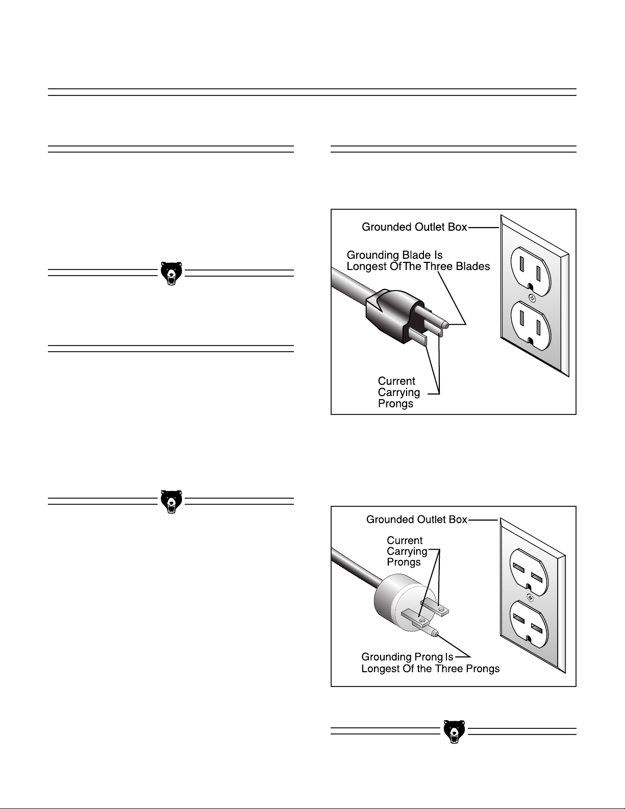
Figure 1b. NEMA 6-15 plug and receptacle.
Figure 1a. NEMA 5-15 plug and receptacle.
The cord set enclosed is equipped with a NEMA
5-15 plug (Figure 1a).
If the bandsaw is rewired to operate on a 220V
power source, the plug must be replaced with a
NEMA 6-15 plug (Figure 1b).
Plug-Type
Circuit Breaker
Amperage Draw
SECTION 3: CIRCUIT REQUIREMENTS
Page 9

G0560 Meat-Cutting Bandsaw -7-
Electrocution or a fire
can result if the machine
is not grounded correctly. Make sure all electrical circuits are grounded. DO NOT use the
machine if it is not
grounded.
If you find it necessary to use an extension
cord with this machine:
• Only use a cord that is rated for standard ser-
vice (Grade S).
• Only use a cord that contains a grounding
prong.
• Use at least a 16 gauge cord if the cord is 50
feet long or less.
• Use at least a 14 gauge cord if the cord is
between 50-100 feet.
• Always repair or replace cords when they
become worn or damaged.
We DO NOT recommend using an extension
cord if you are operating your bandsaw on a 220V
power source.
NOTICE
The wire on the power cord with green or
green and yellow striped insulation is the
grounding conductor.
In the event of an electrical short, grounding
reduces the risk of electric shock by providing a
path of least resistance to disperse electric current. This tool is equipped with a power cord that
has an equipment-grounding prong. The outlet
must be properly installed and grounded in accordance with all local codes and ordinances.
The Model G0560 can be rewired to operate on a
220V power source. The motor must be rewired
according to the wiring diagram on the motor
label. The wiring configuration can also be found
on the inside of the motor wire cover, as well as
on page 33.
This procedure takes moderate electrical skill and
the rewiring job should be inspected by a licensed
electrician before turning the machine ON.
Always check to see if the wires in your circuit are
capable of handling the amperage draw from
your machine, as well as any other machines that
could be operating on the same circuit. If you are
unsure, consult a qualified electrician.
If the circuit breaker trips or the fuse blows regularly, your machine may be operating on a circuit
that is close to its amperage draw capacity.
However, if an unusual amperage draw does not
exist and a power failure still occurs, contact a
qualified electrician.
Extension Cords
Rewiring To 220V
Grounding
Circuit Capacity
Page 10

-8- G0560 Meat-Cutting Bandsaw
1. Adjustable Blade Guard
2. Blade Guide
3. Sliding Table
4. Small Cutting Fence
5. ON/OFF Switch
6. Large Cutting Fence
7. Meat Grinder/Sausage Stuffer
Figure 2. Main view of machine features.
5
4
3
6
1
SECTION 4: MACHINE FEATURES
7
2
Page 11

G0560 Meat-Cutting Bandsaw -9-
This machine left our warehouse in a carefully
packed crate or box. If you discover the machine
is damaged after you have signed for delivery,
please immediately call Customer Service at
(570) 546-9663 for advice.
Save the containers and all packing materials for
possible inspection by the carrier or its agent.
Otherwise, filing a freight claim can be difficult.
When you are completely satisfied with the condition of the shipment, you should inventory the
equipment.
Wear safety glasses during the entire set up
process!
This machine presents
serious injury hazards
to untrained users. Read
through this entire manual to become familiar
with the controls and
operations BEFORE
starting the machine!
Inventory
The Model G0560 is a
heavy machine (127 lbs.
shipping weight). DO
NOT over-exert yourself
while unpacking or moving your machine—get
assistance.
After all the parts have been removed from the
carton, you should have:
Base Unit (Figure 3)
A. Model G0560 Bandsaw Base Unit..............1
Figure 3. Bandsaw base unit.
Unpacking
SECTION 5: SET UP
B. Stand Hardware Bag
—Knob Screw M6-1 x 12..........................17
—Special Hex Bolt M10-1.5 x 16................3
—Hex Bolt M8-1.25 x 20 ............................4
—Carriage Bolt M8-1.25 x 16 ..................22
—Hex Nut M8-1.25 ..................................30
—Flat Washer 8mm ..................................34
—Hex Bolt M6-1 x 20..................................4
—Hex Bolt M6-1 x 12..................................4
—Flat Washer 6mm ....................................8
—Tap Screw #6 x
3
⁄8" ................................12
—Catch Tab..............................................12
Page 12

-10- G0560 Meat-Cutting Bandsaw
Figure 5. Table, fence and grinder pieces.
Figure 6. Motor, drive belt, and switch pieces.
Figure 4. Stand pieces.
Table, Fence and Grinder Pieces (Figure 5)
L. Table ..........................................................1
M. Slide Rail ....................................................2
N. Large Fence................................................1
O. Small Fence................................................1
P. Fence Rod ..................................................2
Q. Fence Bracket ............................................2
R. Table Force Plate ......................................1
S. Grinder Assembly ......................................1
T. Plastic Pusher ............................................1
U. Sausage Stuffer ..........................................1
V. Blade Protection Plate ................................1
W. Blade Guard................................................1
X. Table Guard ................................................1
B
C
L
M
N
Y
Z
AA
BB
CC
O
P
Q
R
S
T
U
V
W
X
H
I
J
F
G
E
D
Motor, drive belt and switch pieces (Figure 6)
Y. Motor w/ Motor Pulley ................................1
Z. Switch Backside Cover ..............................1
AA. Power Switch ..............................................1
BB. Power Cord ................................................1
CC. V-Belt A-53 ................................................1
In the event that any nonproprietary parts are
missing (e.g. a nut or a washer), we would be
glad to replace them, or, for the sake of expediency, replacements can be obtained at your local
hardware store.
Stand Pieces (Figure 4)
C. Front Panel ................................................1
D. Rear Panel ..................................................1
E. Top Panel....................................................1
F. Top Panel “S” Brace ..................................1
G.
Motor Mount Plate
......................................1
H. Plastic Side Panel ......................................2
I. Lower Brace................................................2
J. Foot Hardware
—Rubber Feet ............................................4
—Feet Mount Bracket ................................4
Page 13
G0560 Meat-Cutting Bandsaw -11-
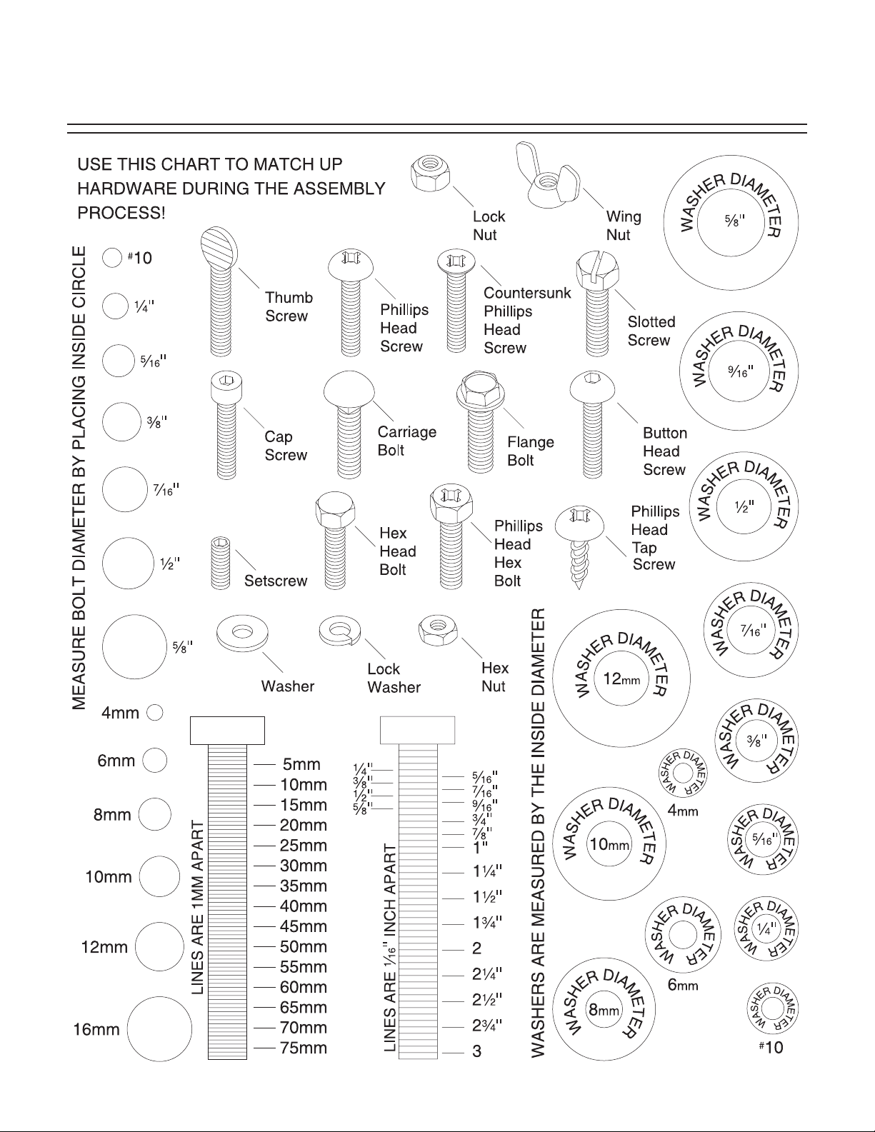
Hardware Recognition Chart
Page 14

-12- G0560 Meat-Cutting Bandsaw
Unsupervised children and
visitors could cause serious
personal injury to themselves with this machine.
Choose a site for placement
in your shop where you can
safely lock visitors and children away when you are not
with them.
Floor Load
The Model G0560 weighs 127 lbs. and has a
base footprint of 16" x 18".
Working Clearances
Consider existing and anticipated needs, size of
material to be processed, and space for auxiliary
stands, work tables or other machinery when
establishing a location for your bandsaw.
Clean Up
The table and guard pieces come with a protective coating. Peel this off before cleaning these
pieces. Clean and sanitize all parts of the saw
that will be in contact with meat or any other food
items. The smaller items and table will fit in most
dishwashers. This is probably the easiest method
of cleaning and sanitizing these parts. For the
larger parts of the saw, if a dishwasher is not
available, clean with a sanitizing agent. See
Section 5: Sanitation for details on sanitizing.
Get in the habit of cleaning your saw thoroughly
to avoid contamination and illnesses.
When cleaning with sanitizers, always follow the recommendations on the manufacturer’s label, and make sure that the
product will do the job for which you
intend. Never use a product that will make
your meat unsafe for human consumption.
Failure to follow this warning may lead to
sickness or death!
Site Considerations
Page 15

G0560 Meat-Cutting Bandsaw -13-
Components and Hardware Needed: Qty
Rubber Feet ......................................................4
Feet Bracket ......................................................4
Hex Bolt M6-1 x 20 ............................................4
Stand Side..........................................................2
Stand Side Brace ..............................................2
Stand Top ..........................................................1
Top Panel “S” Brace ..........................................1
Motor Mounting Bracket ....................................1
Carriage Bolt M8-1.25 x 16 ..............................16
Hex Nut M8-1.25 ..............................................20
Flat Washer 8mm ............................................20
Tools Needed:
10mm Wrench or Socket....................................2
To assemble the stand:
All stand pieces except the rubber feet should be
assembled with the M8-1.25 x 16 carriage bolts,
M8 hex nuts, and 8mm washers.
1. Attach the stand sides to the stand top as
shown in Figure 7. Make sure the side of the
stand with the switch cutout is on the same
side as the V-belt cutout on the top piece.
This will ensure that the switch is in front of
the bandsaw. Do not completely tighten the
carriage bolt nuts at this time.
Stand
2. Place the (4) feet brackets on the stand cor-
ners where the rubber feet will be installed.
3. Insert the (4) M6-1 x 20 hex bolts into the
rubber feet and attach the feet to the stand
corners as shown in Figure 8.
Figure 8. Rubber foot and foot brackets.
Figure 7. Stand sides attached to stand top.
Figure 9. Stand braces attached to stand sides.
4. Attach the side braces to the stand sides as
shown in Figure 9.
Switch Cutout
V-belt Cutout
Rubber Foot
Foot Bracket
Side Braces
Page 16

-14- G0560 Meat-Cutting Bandsaw
Figure 12. Switch & cord installed on stand.
Components and Hardware Needed: Qty
Switch ................................................................1
Switch Cover ......................................................1
Power Cord ........................................................1
Tools Needed:
Phillips Head Screwdriver ..................................1
To install the switch and power cord:
Mount the switch on the stand side with the (2)
10-24 x 1" Phillips screws, 10-24 nuts, and star
washers.
1. Place the strain relief into the hole on the
stand side. Thread the plastic nut onto the
back side of the strain relief.
2. Make sure the plastic setscrew is withdrawn
enough to allow the cord to come through
the strain relief, then push the end of the
cord with the wires through the strain relief.
3. Allow enough room for the red and black
wires to reach the switch and the green wire
to reach the ground (hole below the switch).
4. Tighten the plastic setscrew to secure the
cord in place. Mount the switch and cord to
the stand side as shown in Figure 12.
Switch & Cord
6. Attach the motor mounting plate with the top
panel “S” brace to the inside of the stand as
shown in Figure 11.
Figure 10. Motor mounting bracket attached to
the top panel “S” brace.
5. Attach the motor mounting plate to the top
panel “S” brace with (2)
5
⁄16"-18 x 1⁄2" carriage
bolt,
5
⁄16" washers and 5⁄16"-18 hex nuts
(Figure 10).
7. Turn the stand over on its feet to square out
the sides and tighten the remaining loose
nuts.
Figure 11. Top brace to stand top.
Page 17

G0560 Meat-Cutting Bandsaw -15-
Figure 13. Motor mounted to motor mount.
Components and Hardware Needed: Qty
Motor ..................................................................1
Hex Bolt M8-1.25 x 20........................................4
Hex Nut M 8-1.25 ..............................................4
Flat Washer 8mm ..............................................8
Tools Needed:
Wrench or Socket 10mm....................................1
To install the motor:
1. Place the motor on the mounting plate so the
motor pulley is directly under the pulley slot
in the top of the stand.
2. Fasten the motor onto the motor mount (as
shown in Figure 13) with the hex bolts, hex
nuts, lock washers and flat washers. The
washers should be placed on both sides of
the motor mount.
Motor
Figure 14. Wiring to switch plate.
After everything is wired correctly, take off the
nuts that hold the switch over the mounting hole
in the stand. Slide the rubber cover over the back
of the switch so no metal contacts are exposed.
Push the mounting screws through the holes on
the ends of the cover and thread the nuts back on
the screws. Tighten them securely, but not tight
enough to ruin the rubber.
The diagram in Figure 14 shows the proper
wiring of the motor and the power cord. The
ground wires mount underneath the switch with
the 10-24 x
1
⁄2" Phillips screw, nut and star washer. Do not pinch the wires while installing them. If
they will not reach, carefully cut back the outer
layer of the black cord. Do not cut insulation on
the smaller wires inside!
Wiring
Page 18

-16- G0560 Meat-Cutting Bandsaw
Before you put on the V-belt, make sure that the
motor pulley and the upper pulley are reasonably
aligned. To do this, loosen the setscrew on the
motor pulley, adjust the motor pulley so it is in-line
with the upper pulley, then tighten the setscrew.
To put on the V-belt:
1. Loosen the (4) motor mount bolts.
2. Raise the motor up and fit the V-belt in the
pulley grooves, then let the motor down.
3. Place slight pressure on the motor to tension
the belt and tighten the (4) motor mount
bolts. Make sure that the motor does not
twist and double check the pulley alignment.
Adjust the positioning as needed.
4. Check for approximately
1
⁄4" deflection. If the
belt is not tensioned correctly, repeat steps
1 and 3 until it is correct.
V-Belt
Figure 15. Bandsaw unit on stand.
Figure 16. Installing special hex bolt.
Components and Hardware Needed: Qty
Bandsaw Base Unit ............................................1
Special Hex Bolt M10-1.5 x 16 ..........................3
2. Line up the holes in the corner of the stand
with the holes on the bottom of the bandsaw
unit.
3. Fasten the stand to the bandsaw unit with
the (3) M10-1.5 x 16 special hex bolt as
shown in Figure 16.
Bandsaw Unit
The Model G0529
weighs 127 lbs.
Personal injury could
occur if the machine is
moved without additional assistance. Seek help
when moving or lifting
the machine.
To install the bandsaw unit onto the stand:
1. Place the bandsaw base unit onto the stand
as shown in Figure 15. Get help so you do
not strain yourself.
Page 19

G0560 Meat-Cutting Bandsaw -17-
Stand Covers
Figure 18. Catch tab in place on stand cover.
Components and Hardware Needed: Qty
Tap Screws #6 x
3
⁄8" ........................................12
Catch Tabs ......................................................12
Stand Covers......................................................2
Tools Needed:
Phillips Head Screwdriver ..................................1
The stand covers need catch tabs installed in all
the predrilled holes as shown in Figure 17 & 18.
Figure 17. Stand covers with catch tabs.
The stand covers fit inside the stand openings
and attach by turning the catch tabs over the
edges of the stand.
Figure 19. Table guard installed.
The blade and table guards prevent contaminants from falling into the saw.
Components and Hardware Needed: Qty
Blade Guard ......................................................1
Table Guard ......................................................1
Knob Screw M6-1 x 12 ......................................6
To install the guards:
1. Place the table guard around the bandsaw
throat on the top edge as shown in Figure
19.
Blade & Table
Guards
2. Secure the table guard in place with a knob
screw on each side of the guard.
3. Place the blade guard around the side of the
bandsaw covering the blade as shown in
Figure 20
.
Page 20

-18- G0560 Meat-Cutting Bandsaw
Figure 21. Installing rails on table.
The sliding table allows you to move the blade
through the meat.
Components and Hardware Needed: Qty
Sliding Table ......................................................1
Rail ....................................................................2
Force Plate ........................................................1
Knob Screw M6-1 x 12 ......................................4
Hex Bolt M6-1 x 12 ............................................4
Flat Washer 6mm ..............................................4
To install the sliding table:
1. Secure one end of each rail to the underside
of the sliding table as shown in Figure 21.
Note—Secure the rail ends to the closed
side of the sliding table.
Table
Figure 20. Blade guard installed.
4. Secure the blade guard in place with two
knob screws on each side.
Page 21

G0560 Meat-Cutting Bandsaw -19-
Figure 23. Securing rails in the sliding table.
Figure 22. Installing force plate.
4. Secure the rails to the end of the table using
the knob screws as shown in Figure 23.
2. Slide the bandsaw blade through the slot in
the sliding table and place the table on the
rollers. Note—Be careful when placing the
table on the saw. The other end of the rails
are not secured to the table.
3. Secure the force plate under the open edge
of the table with the M6-1 x 12 knob screws
as shown in Figure 22.
5. Tighten the rails in place so that they slide in
the roller groove.
Note—This table adjustment may take some
trial and error. It is best to position the inside
rail so the blade is centered in the slot, then
squeeze the outer rail into the roller groove
and tighten the knob screws. It is important
that the rails are secure in the rollers and the
blade does not make contact with the table.
6. Check to make sure the rails are in the roller
grooves and that the table slides smoothly
(Figure 24).
Figure 24. Checking table position.
Page 22

-20- G0560 Meat-Cutting Bandsaw
Figure 25. Fence supports to table.
Figure 26. Fences assembled.
Figure 27. Fences installed on supports.
The fences allow you to support the meat as you
slide it through the blade while also controlling the
thickness of cut.
Components and Hardware Needed: Qty
Fence Support Brackets ....................................2
Hex Bolts M6-1 x 20 ..........................................4
Fence Shafts ......................................................2
Fences................................................................2
Knob Screws M6-1 x 12 ....................................4
Flat Washer ........................................................4
Tools Needed:
Wrench 10/12mm ..............................................1
To install the fence:
1. Use the M6-1 x 20 hex bolts to attach the
fence brackets to the table as shown in
Figure 25.
Fence
2. Insert the fence shafts into the fences and
secure them in place with the knob screws
(Figure 26).
3. Slide the long fence into the bracket on the
left and the short fence into the bracket in
front (Figure 27).
4. Secure the fence assemblies in the brackets
with knob screws.
Page 23

G0560 Meat-Cutting Bandsaw -21-
Meat Grinder
The Model G0560 comes with a meat grinder.
Before assembling this for use, clean and sanitize
its parts. See Section 5: Sanitation for details on
sanitizing. Figure 28 shows the meat grinder
components.
Figure 28. Meat grinder components.
Figure 29. Keyway location.
Figure 30. Sausage stuffer attachment.
To install the meat grinder:
1. Disconnect the machine from the power
source!
2. Line up the fixed key on the meat grinder to
the keyway on the housing shown in Figure
29.
Keyway
The meat grinder comes with a sausage stuffer
attachment.
To install the sausage stuffer:
1. Remove the collar from the end of the meat
grinder housing.
2. Fit the collar over the sausage stuffer.
3. Place the collar back on the housing as
shown in Figure 30, and thread it tight so it
is secured to the housing.
The meat grinder should not be attached
to the saw when not in use. The open
chute and spinning auger easily invite an
accident if not being attended to.
The meat grinder should not be attached
to the saw when not in use. Meat fat is
required to lubricate the grinder components during operation. Grinder will be
damaged if allowed to turn “dry”.
Sausage
Stuffer
Collar
3. Slide the meat grinder all the way into the
housing and tighten the split collar to secure
the grinder in place.
Page 24

-22- G0560 Meat-Cutting Bandsaw
Damage to your eyes and ears could result
from using this machine without proper protective gear. Always wear safety glasses and
hearing protection when operating this
machine.
The Model G0560 is operated by an ON/OFF
paddle switch that is clearly labeled on the side of
the stand.
This switch is locked out when the key is removed
to protect against accidental operation (Figure
31).
Figure 32. Blade guard.
Figure 31. Switch lock out.
Blade Guard
Figure 32 shows the blade guard controls. The
blade guard protects the operator from accidental
contact with the part of the blade that is not being
used.
The star knob on the guide rail allows you to raise
and lower the blade guard and blade guide
assembly. Keep the blade guide assembly within
an inch of the material you are cutting. This will
provide adequate support for the blade where the
pressure is greatest. This adjustment is crucial
for safe operation when cutting through bone!
SECTION 6: OPERATIONS
Guide Rail
Star Knob
Blade Guard
Page 25

G0560 Meat-Cutting Bandsaw -23-
Blade Tension
The bandsaw blade must be adequately tensioned so that it will cut straight and not fall off the
wheel during operation.
To tension the bandsaw blade:
1. Disconnect the machine from the power
source!
2. Remove the thumbscrew that secures the
upper cover, then pull the upper cover off the
bandsaw unit to expose the upper wheel.
3. Turn the tension bolt (shown in Figure 35)
counterclockwise to decrease the tension
and clockwise to increase the tension.
4. Tension the blade so that it deflects approximately
1
⁄4" with moderate pressure from your
finger.
Figure 35. Blade tension bolt.
Disconnect power to the
machine when performing any adjustments or
maintenance. Failure to
do this may result in serious personal injury.
Figure 34. Lower blade guide.
The upper blade guides shown in Figure 33 support the blade from moving side-to-side while cutting. These should be adjusted to approximately
0.004" (about the thickness of a dollar bill) away
from the blade and should be behind the gullet of
the blade teeth.
Figure 33. Upper blade guide.
Blade Guides
The lower blade guides shown in Figure 34 are
underneath the table. These can be adjusted with
a screwdriver and should be set in the same manner as the upper blade guides.
Blade Guides
Blade Guides
Gullet Line
Blade Guide
Tension bolt
Page 26

-24- G0560 Meat-Cutting Bandsaw
Changing Blades
In the event that you need to change blades or
remove the current blade for cleaning purposes,
follow the instructions below:
1. Disconnect the machine from the power
source!
2. Remove the force plate from the end of the
table.
3. Slide the table off the rollers and remove it
from the bandsaw unit.
4. Remove the stainless steel blade covers.
5. Move the blade guides away from the blade,
so the blade can easily slide out and away
from the blade guide assembly.
6. Remove the V-belt.
7. Release the tension from the blade by turn-
ing the blade tension bolt counterclockwise.
8. Remove the thumbscrew that holds the
upper cover in place, then pull the upper
cover off of the bandsaw unit.
9. Put on a pair of leather gloves to protect your
hands from the sharp edges of the blade.
Carefully remove the blade as shown in
Figure 37.
Figure 37. Removing the bandsaw blade.
Figure 36. Blade tracking controls.
The bandsaw blade must be properly tracked (or
centered) on the wheels.
To track the blade:
1. Disconnect the machine from the power
source!
2. Remove the upper wheel cover from the
bandsaw.
3. The blade tracking controls are shown in
Figure 36. Each setscrew moves that por-
tion of the wheel in or out. For example, the
top setscrew controls the top of the wheel,
the left setscrew controls the left of the wheel
and so forth.
3. Adjust the tracking setscrews so that the
blade remains in the center of the wheel
when you spin the wheel by hand. After the
blade appears to be tracking correctly, spin
the wheel at least three full times to ensure
that the blade remains centered, and then
replace the upper wheel cover, turn on the
machine and test the blade tracking. If there
are problems, repeat steps 1-3.
Blade Tracking
Page 27

G0560 Meat-Cutting Bandsaw -25-
The support bearing backs the blade during operation. As mentioned in the “Blade Guard” instructions, the blade guide assembly (with the support
bearing) should be lowered to within an inch from
the material you are cutting to be most efficient.
The support bearing shown in Figure 38 should
be approximately 0.016" away from the back of
the blade. This is about four thicknesses of a dollar bill. To adjust the support bearing, loosen the
support bearing shaft thumbscrew and slide the
support bearing forward or backward as necessary.
10. Blade installation is the opposite of removal.
Once the blade is installed, remember to tension it appropriately, set the blade guides,
and replace the V-belt.
Make sure all components that were
removed have been placed back in their
original position, are adjusted correctly,
and all guards are in place before you plug
the bandsaw back into the power outlet. An
injury may occur if this caution is ignored.
Once assembly is complete and adjustments are
done to your satisfaction, you are ready to start
the machine.
Press the START button. Make sure that your finger is poised on the STOP button just in case
there is a problem. The bandsaw should run
smoothly with little or no vibration or rubbing noises. Strange or unnatural noises should be investigated and corrected before operating the
machine further.
Run the Model G0560 for a short time to ensure
that the moving parts are working properly with
no excessive vibration. If any problem develops,
correct it before attempting to use the machine.
If you cannot locate the source of unusual noises,
immediately contact our service department at
(570) 546-9663.
Test Run
Figure 38. Support bearing.
Support Bearing
Support Bearing
Thumbscrew
Page 28

-26- G0560 Meat-Cutting Bandsaw
NOTICE
The following section was designed to provide a basic understanding of the types of
items that can be cut with the meat-cutting
bandsaw. This manual is in no way a guide
to cutting meat, dressing animals or safe
meat handling techniques. WE STRONGLY
RECOMMEND that you read books, magazines or take lessons that specifically deal
with meat cutting and animal dressing
applications.
Read the entire manual
before making any cuts
with your bandsaw.
Serious personal injury
may result if safety or
operational information
is not understood or followed.
Cutting Meat
Your Model G0560 Meat-Cutting Bandsaw will
cut through any fresh meat and almost all frozen
meat.
To cut meat with your bandsaw:
1. Use the side fence to gauge the thickness of
your desired cut. The front fence should
brace the meat. Make sure that either of the
fences or their rails will not be in line with the
cut.
2. Turn the power ON and slowly guide the
meat into the blade by sliding the table. With
frozen meat, pay close attention to the rate
at which you feed the meat into the moving
blade. All cuts should be slow and smooth. If
you hear the motor slow down or struggle
with the cut, stop the cut.
3. Clear the slice you just cut and slide the
meat toward the side fence. You can make
successive cuts and the following slices will
be the same thickness as the first.
This bandsaw can cut
your fingers off or cause
other bodily harm. Use a
wooden push stick when
cutting small pieces and
always properly support
any item you cut.
Bacteria from raw meat has been frequently
linked to illness and even death! Describing
proper meat handling techniques outside of
cleaning the bandsaw is beyond the scope of
this manual. If you are unclear about sanitary
meat handling practices, contact your local
Board of Health or the USDA to research the
proper methods of meat handling.
Page 29

G0560 Meat-Cutting Bandsaw -27-
This bandsaw can cut
your fingers off or cause
other bodily harm. Use a
wooden push stick when
cutting small pieces and
always properly support
any item you cut.
The meat grinder can
easily grind your fingers.
Never use your fingers to
push meat into the
grinder. Always use the
provided pusher and
remove the meat grinder
when not in use.
Besides meat, this bandsaw can cut through
bone too.
When cutting bone:
Feed the bone into the blade slowly. If you hear
the motor slow down during cutting, stop cutting
at once. DO NOT twist the blade during the cut.
The blade may bind or break.
The meat grinder is great for grinding hamburger
or sausage. The grinder automatically engages
when it is mounted to the bandsaw unit.
To use the meat grinder:
1. Make sure that all the grinder components
are cleaned and sanitized thoroughly before
using them.
2. Lower the blade guard as low as it will go
and lock it in place.
3. Prepare a place for the ground meat to exit
the grinder.
4. Drop pieces of meat into the grinder, one at
a time. Use the pusher to help the meat into
the spinning auger, but do not overload the
grinder.
5. Always clean and sanitize all parts of the
grinder that have been exposed to meat or
food particles.
DO NOT have the meat grinder installed on
the bandsaw when not in use.
Grinding MeatCutting Bone
Page 30

-28- G0560 Meat-Cutting Bandsaw
Cleaning the Saw
Figure 39. Pieces disassembled for cleaning.
To clean your bandsaw after use:
1. Remove the table, the blade guards, the
fences, and the meat grinder (Figure 39).
2. If used, disassemble the meat grinder
(Figure 40).
Figure 40. Meat grinder components
disassembled for cleaning.
3. Take off the upper wheel cover and open the
cabinet door.
Always be as thorough as
possible when cleaning and
sanitizing your meat cutting
bandsaw components. Any
parts that have been
exposed to raw meat or bone
may harbor or develop bacteria that may cause illness or
death if left uncleaned.
Cleaning the bandsaw
while it is plugged in may
cause severe electrical
shock! Always disconnect the power before
attempting any cleaning
or maintenance operations, and after cleaning,
never connect the bandsaw to a power source
until it is dry. Failure to
follow this warning may
result in severe injury or
even death.
When cleaning with sanitizers, always follow the
recommendations on the
manufacturer’s label, and
make sure that the product
will do the job for which
you intend. Never use a
product that will cause
exposed surfaces to render meat unsafe for human
consumption. Failure to
follow this warning may
lead to sickness or death!
SECTION 7: CLEANING/SANITIZING
Page 31

G0560 Meat-Cutting Bandsaw -29-
Proper Sanitation
All surfaces and working parts that have been
exposed to meat must be properly sanitized after
each use.
Dishwashers are a good option because they
sanitize with heat. For all pieces that will not fit in
the dishwasher, or if a dishwasher is not available, chemical sanitizers like bleach or iodo-
pher solution are good options. There are also
other chemical sanitizers on the market that
serve the same function. When using chemical
sanitizers, make sure they are designed to do the
job, and strictly follow the manufacturer’s recommendations for proper use.
Proper sanitation with chemical sanitizers
requires a process before the actual sanitizer is
applied.
The following is an effective method to prepare an item for sanitation:
1. Gather all the items that need to be cleaned.
Remove the largest particles of foodstuffs
into a proper garbage container. Rinse all
items to remove as many of the leftover particles as possible. Set the items aside.
2. Prepare the sink. Wash and scrub all sink
compartments with dish soap and hot water.
Rinse these compartments thoroughly.
4. Remove the blade from the wheels of the
bandsaw (as discussed in the “Changing
Blades” instructions). Sanitize all removed
pieces from the meat grinder and bandsaw,
according to the following sanitation instructions. If you have access to a dishwasher,
use it to sanitize the parts that will fit.
5. Clean the wheels and any other part of the
bandsaw unit that may have been exposed
to raw meat with a direct application sanitizer (read “Proper Sanitation” instructions).
3. Fill a sink with soapy water, submerge the
item and scrub the entire surface thoroughly.
4. Using hot water, rinse the newly cleaned
item in the empty compartment, until all visible suds have been removed. Repeat this
process for all of the items that need to be
sanitized. If the soapy water starts to get
hazy, drain and rinse the sink, then fill with
more soapy water.
The items are now ready to be sanitized. Some
sanitizers require direct applications, while others
are designed to be diluted in water and used to
soak the item for a specified period of time. The
best method for choosing a chemical sanitizer is
to do the research and determine which product
is best for your particular situation.
One simple sanitizer that can be used for many
applications is regular bleach. To use bleach as a
sanitizer, wash, scrub, and rinse your sink. For all
non-porous surfaces (includes all parts of this
bandsaw), fill the sink with one tablespoon of
bleach per gallon of cool water. Do not use
bleach that contains odor masking agents or surfactants. These have not been proven effective
for this type of sanitation. Submerge each item for
two minutes. For large items, submerge each
side for the specified amount of time until you
have covered the entire area. Allow to air dry. Do
not rinse these items after sanitation!
If your raw meat comes into contact with nonporous surfaces (wood), clean as described
above and soak these surfaces for two minutes in
a solution of 3 tablespoons of bleach to one gallon of cool water. Rinse these items well!
Page 32

-30- G0560 Meat-Cutting Bandsaw
Regular periodic maintenance on your Model
G0560 Meat-Cutting Bandsaw ensures its optimum performance. Make a habit of inspecting
your bandsaw each time you use it.
Check for the following conditions and repair or
replace when necessary.
1. Loose mounting bolts.
2. Worn switch.
3. Worn or damaged cords and plugs.
4. Damaged V-belt.
5. Any other condition that could hamper the
safe operation of this machine.
V-Belt
Avoid getting grease or oil on the V-belt or pulleys. Check the V-belt, as part of a monthly
inspection for proper tension and belt condition.
Cracking and glazing could result in belt failure.
Replace the belt if such conditions appear.
Maintain your table and blade with a thin film of
food grade lubricant that will not support bacteria
growth and will not become rancid. These qualities are important because some food grade oils
will become rancid over time and may cause illnesses. Make sure that the product you use is
specifically designed for protecting food processing machinery. Always follow the manufacturer’s
recommendations when using their products.
The wheel bearings are shielded and lubricated
for life; thus, they require no maintenance
throughout their lifespan. Occasionally lubricate
the tracking and height adjustment controls with
the same food grade lubricant that you use on the
table.
DO NOT lubricate the meat grinder. The meat
processed in the meat grinder naturally lubricates
the grinder.
Disconnect power to the
machine when performing any adjustments or
maintenance. Failure to
do this may result in serious personal injury.
Lubrication
Table & Blade
General
SECTION 8: MAINTENANCE
Page 33

G0560 Meat-Cutting Bandsaw -31-
The following pages contain the machine data
sheets, wiring diagram, parts diagrams, parts lists,
and the Warranty/Return information for the
Model G0560.
If you need parts or help in assembling your
machine, or if you need operational information,
call the Grizzly Service Department. Trained service technicians will be glad to help you.
If you have any comments regarding this manual,
please write to Grizzly at the address below:
Grizzly Industrial, Inc.
C
/O Technical Documentation
P.O. Box 2069
Bellingham, WA 98227-2069
SECTION 7: REFERENCE INFO
We recommend you keep a copy of our current
catalog for complete information regarding
Grizzly's warranty and return policy. If you need
additional technical information relating to this
machine, or if you need general assistance or
replacement parts, please contact the Service
Department at the location listed below.
Grizzly Industrial, Inc.
1203 Lycoming Mall Circle
Muncy, PA 17756
Phone: (570) 546-9663
Fax: (800) 438-5901
E-Mail: techsupport@grizzly.com
Web Site: http://www.grizzly.com.
Page 34

-32- G0560 Meat-Cutting Bandsaw
Design Type .................................................................................................... Floor Model
Overall Dimensions:
Table ..................................................................................................22
1
⁄2" L x 163⁄4" W
Height ......................................................................................................................56"
Height From Floor to Table ..................................................................................35
3
⁄8"
Width of Unit ............................................................................................................19"
Shipping Weight ................................................................................................138 lbs.
Weight in Place ................................................................................................127 lbs.
Box Size ............................................................................36
1
⁄4" L x 191⁄2" W x 161⁄2" H
Footprint ..........................................................................................................16" x 18"
Cutting Capacity:
Height ......................................................................................................................9
1
⁄4"
Throat ......................................................................................................................9
3
⁄4"
Blade Length ........................................................................................................77
1
⁄2"
Blade Speed....................................................................................................990 FPM
Range of Table Slide Movement (with fence) ........................................................8
1
⁄4"
Max Width of Cut of Table Slide Movement (with fence)........................................8
1
⁄2"
Fence Adjustment ......................................................................................................8"
Sausage Grinder Speed ................................................................................380 RPM
Construction:
Table ......................................................................................................Stainless Steel
Wheels ....................................................................................Aluminum - Ball Bearing
Fence ..............................................................................................Die Cast Aluminum
Wheel Covers....................................................................................Pre-Formed Steel
Guides............................................Uppper Bakelite guide, Rear Ball Bearing Support
Motor:
Type ............................................................................TEFC Capacitor Start Induction
Horsepower ..........................................................................................................
3
⁄4 HP
Phase ⁄ Cycle ..............................................................................Single Phase / 60 Hz
Voltage ......................................................................................................110V / 220V
Amps................................................................................................................12A / 6A
RPM..............................................................................................................1725 RPM
Bearings ........................................................Shielded & Permanently Lubricated Ball
Switch ........................................................................................ Toggle Safety Switch
Features:
................................................Includes
5
⁄8" Blade, Meat Grinder, and Sausage Stuffer
............................................................................Sliding Table (Ball Bearing Support)
Specifications, while deemed accurate, are not guaranteed.
11-21-03
Customer Service #: (570) 546-9663 • To Order Call: (800) 523-4777 • Fax #: (800) 438-5901
GRIZZLY MODEL G0560 MEAT-CUTTING BANDSAW
MACHINE DATA
SHEET
Page 35

G0560 Meat-Cutting Bandsaw -33-
G0560 Wiring Diagram
Page 36

-34- G0560 Meat-Cutting Bandsaw
14
20
29
8
17
3
76
59
63
62
28
60
64
57
61
22
65
31
30
56
66
21
24
69
23
32
33
26
57
34
25
13
74
18
46
19
68
12
11
6
5
72
46
8
4
67
1
88
82
CAUTION
85
ALWAYS REMOVE
MEAT GRINDER WHEN
RESULT.
TO GRINDER WILL
NOT IN USE. DAMAGE
83
86
87
35
84
70
43
40
38
79
39
41
71
44
78
42
77
73
13
48
52
58
20
14
46
2
3
49
55
3
81
50
80
3
53
Page 37

G0560 Meat-Cutting Bandsaw -35-
REF PART # DESCRIPTIONREF PART # DESCRIPTION
49 PFB01M Flange Bolt M6-1 X 12
50 P0560050 Lower Guide Seat
51 PW03M Flat Washer 6mm
52 P608ZZ Ball Bearing 608ZZ
53 PB07M Hex Bolt M8-1.25 X 25
55 P0560055 Clamping Luge
56 P0560056 Blade Guide Block
57 P0560057 Star Knob M6-1 X 12
58 P0560058 Star Knob M8-1.25 X 20
59 P0560059 Screw Bar
60 PTS001M Thumb Screw M6-1 X 16
61 P0560061 Blade Guide Bar
62 P6200ZZ Ball Bearing 6200ZZ
63 PR01M Ext Retaining Ring 10MM
64 P0560064 Blade Guide Block
65 PSS01M Set Screw M6-1 X 10
66 P0560066 Blade Guide Holder
67 P0560067 Connector Fixed Plate
68 P0560068 Lower Wheel Fixed Plat
69 P0560069 Rod Set Screw
70 P0560070 Blade Guard
71 PR21M Int Retaining Ring 35MM
72 PLW04M Lock Washer 8MM
73 PN09M Hex Nut M12-1.75
74 P0560074 Sausage Stuffer
76 P0560076 Pusher
77 PSS05M Set Screw M5-.8 X 10
78 PLW05M Lock Washer 12MM
79 PW04M Flat Washer 10MM
80 PCB12M Carriage Bolt M6-1 x 12
81 PCB06M Carriage Bolt M8-1.25 X 16
82 P0560082 Hand Near Blade Label
83 P0560083 Safety Glasses Label
84 P0560084 Machine ID Label
85 P0560085 Unplug 110V Label
86 P0560086 Wash Hands Label
87 G9987 Grizzly Logo Plate
88 P0560086
Meat Grinder Label
1 P0560001 Bandsaw Base
2 PN03M Hex Nut M8-1.25
3 PW01M Flat Washer 8MM
4 P0560004 Blade Cover
5 P0560005 Lower Blade Wheel
6 P0560006 Set Bearing
8 PSS01M Set Screw M6-1 X 10
11 PB10M Hex Bolt M6-1 X 25
12 PN01M Hex Nut M6-1
13 PN03M Hex Nut M8-1.25
14 PN01M Hex Nut M6-1
17 PVA53 V-Belt A-53 4l530
18 P0560018 Pulley
19 P6204 Ball Bearing 6204ZZ
20 PB08M Hex Bolt M6-1 X 20
21 P0560021 Bracket
22 P0560022 Grinding Hopper
23 P6203 Ball Bearing 6203ZZ
24 PR18M Ext Retaining Ring 17MM
25 PK23M Key 5 X 5 X 25
26 P0560026 Shaft
28
PCB18M Carriage Bolt M8-1.25 X 45
29 P0560029 Square Knob M8-1.25
30 P0560030 Shaft, Thrust
31 P0560031 Bushing
32 P0560032 Reamer
33 P0560033 Filter Cover #4
34 P0560034 Lock Cover
35 P0560035 Upper Cover
38 PR05M Ext Retaining Ring 15MM
39 P6202 Ball Bearing 6202ZZ
40 P0560040 Hex Bolt M10-1.5 X 115
41 P0560041 Bracket
42 P0560042 Shaft Bracket
43 P0560043 Upper Blade Wheel
44 P0560044 Blade
46 PB09M Hex Bolt M8-1.25 X 20
48 PN01M Hex Nut M6-1
G0560 Main Saw Assembly
Page 38

-36- G0560 Meat-Cutting Bandsaw
REF PART # DESCRIPTIONREF PART # DESCRIPTION
113 PS01 Phlp Hd Scr 10-24 X 1⁄2
114 PS22 Phlp Hd Scr 10-24 X 5⁄8
115 P0560115 Motor Pulley
116 P0560116 Switch Plate
117 P0560117 L Type Set Plate
118 P0560118 Side Cover
119 P0560119 Rubber Pad
120 PN03M Hex Nut M8-1.25
121 PW01M Flat Washer 8MM
122 PCB06M Carriage Bolt M8-1.25 X 16
123 P0560123 Switch Box
124 PTLW02M Ext Tooth Washer 5MM
125 PN07 Hex Nut #10-24
126 P0560126 Clamp Door
127
PHTEK18M Tap Screw M3.5 X 10
128 P0560128 Set Bolt
129 PB09M Hex Bolt M8-1.25 X 20
130 PLABEL-14 Electricity Label
131 P0560131 Read Manual Label
101 P0560101 Face Plate
102 P0560102 Rear Plate
103 P0560103 Front Plate
104 P0560104 Lower Bracket
105 P0560105 Motor Plate
106 P0560106 Upper Bracket
107 P0560107 Motor
107-1 PLABEL-38 Gen Motor Label
107-2 P0560107-2 G0560 Motor Data Label
107-3 P0560107-3 Motor Fan Cover
107-4 P0560107-4 Motor Fan
107-5 P0560107-5 Capacitor Cover
107-6 P0560107-6 Start Capacitor 200M 125V
107-7 P0560107-7 Motor Wiring Box
108 P0560108 Motor Cord
109 P0560109 Set Bolt M6-1 X 6
110 P0560110 Cord Bushing
111 P0560111 Power Cord
112 P0560112 Switch
G0560 Stand & Motor Assembly
Motor Components
107-1
R
T
107-2
107-3
107-4
107-7
107-5
107-6
122
118
120
121
122
102
117
119
127
126
101
128
104
106
122
121
105
107
115
120
121
121
129
121
120
108
109
123
125
130
131
111
110
116
114
113
112
124
113
124
103
119
Page 39

G0560 Meat-Cutting Bandsaw -37-
REF PART # DESCRIPTIONREF PART # DESCRIPTION
216 PS14M Phlp Hd Scr M6-1 X 12
217
PFB08M Flange Bolt M5-.8 X 10
218 PR57M Int Retaining Ring 22mm
219 P608ZZ Ball Bearing 608ZZ
220 PCB12M Carriage Bolt M6-1 X 12
221 PFN02M Flange Nut M6-1
222 PW03M Flat Washer 6MM
223
PFH07M Flat Hd Screw M5-.8 X 10
224
PN06M Hex Nut M5-.8
225 P0560225 Knob Bolt M6-1 X 12
226 PB83M Hex Bolt M6-1 X 16
227 P0560227 Left-support
228 PW02M Flat Washer 5MM
229 PN01M Hex Nut M6-1
201 P0560201 Table (sliding)
202 P0560202 Rollers
203 P0560203 Stand Rod
204 P0560204 Guard Cover
205 P0560205 Roller Shaft
206 P0560206 Fixed Plate
207 P0560207 Right-support
208 P0560208 Pusher
209 P0560209 Roller Fixed Plate
210 P0560210 Left Fence
211 P0560211 Supporter
212 P0560212 Guide Rail
213 PB02M Hex Bolt M6-1 X 12
214 PB08M Hex Bolt M6-1 X 20
215 PW03M Flat Washer 6MM
G0560 Sliding Table Assembly
214 215
213
211
203
208
201
223
210
216
217
218
219
202
205
214
215
220
222
228
224
207
212
206
227
225
225
209
226
222
213
226
229
221
204
Page 40

-38- G0560 Meat-Cutting Bandsaw
Grizzly Industrial, Inc. warrants every product it sells for a period of 1 year to the original purchaser from
the date of purchase. This warranty does not apply to defects due directly or indirectly to misuse, abuse,
negligence, accidents, repairs or alterations or lack of maintenance. This is Grizzly’s sole written warranty
and any and all warranties that may be implied by law, including any merchantability or fitness, for any particular purpose, are hereby limited to the duration of this written warranty. We do not warrant or represent
that the merchandise complies with the provisions of any law or acts unless the manufacturer so warrants.
In no event shall Grizzly’s liability under this warranty exceed the purchase price paid for the product and
any legal actions brought against Grizzly shall be tried in the State of Washington, County of Whatcom.
We shall in no event be liable for death, injuries to persons or property or for incidental, contingent, special, or consequential damages arising from the use of our products.
To take advantage of this warranty, contact us by mail or phone and give us all the details. We will then
issue you a “Return Number,’’ which must be clearly posted on the outside as well as the inside of the carton. We will not accept any item back without this number. Proof of purchase must accompany the merchandise.
The manufacturers reserve the right to change specifications at any time because they constantly strive to
achieve better quality equipment. We make every effort to ensure that our products meet high quality and
durability standards and we hope you never need to use this warranty.
Please feel free to write or call us if you have any questions about the machine or the manual.
Thank you again for your business and continued support. We hope to serve you again soon.
WARRANTY AND RETURNS
Page 41

CUT ALONG DOTTED LINE
___Other__________________________________________________
9. How many of your woodworking machines are Grizzly? _____________
10. Which benchtop tools do you own? Check all that apply.
___1" x 42" Belt Sander ___6" - 8" Grinder
___5" - 8" Drill Press ___Mini Lathe
___8" Table Saw ___10" - 12" Thickness Planer
___8" - 10" Bandsaw ___Scroll Saw
___Disc⁄Belt Sander ___Spindle⁄Belt Sander
___Mini Jointer
___Other__________________________________________________
11. How many of the machines checked above are Grizzly? ____________
12. Which portable⁄hand held power tools do you own? Check all that apply.
___________________________________________________________
___________________________________________________________
___________________________________________________________
13. What machines⁄supplies would you like Grizzly Industrial to carry?
___________________________________________________________
___________________________________________________________
___________________________________________________________
14. What new accessories would you like Grizzly Industrial to carry?
___Builders Hardware ___Hand Tools
___Fasteners ___Wood Components
___Other__________________________________________________
15. What other companies do you purchase your tools and supplies from?
__________________________________________________________
__________________________________________________________
16. Do you think your purchase represents good value?
___Yes ___No
17. Would you recommend Grizzly Industrial to a friend?
___Yes ___No
18. Would you allow us to use your name as a reference for Grizzly customers
in your area? Note: We never use names more than three times.
___Yes ___No
19. Comments:__________________________________________________
__________________________________________________________
___________________________________________________________
___________________________________________________________
1. How did you learn about us?
___Advertisement ___Friend
___Catalog ___Card Deck
___World Wide Web
___Other__________________________________________________
2. Which of the following magazines do you subscribe to.
___American Woodworker ___Practical Homeowner
___Cabinetmaker ___Shop Notes
___Family Handyman ___Today’s Homeowner
___Fine Homebuilding ___WOOD
___Fine Woodworking ___Wooden Boat
___Home Handyman ___Woodshop News
___Journal of Light Construction ___Woodsmith
___Old House Journal ___Woodwork
___Popular Mechanics ___Woodworker
___Popular Science ___Woodworker’s Journal
___Popular Woodworking ___Workbench
___Other__________________________________________________
3. Which of the following woodworking⁄remodeling shows do you watch?
___Backyard America ___The New Yankee Workshop
___Home Time ___This Old House
___The American Woodworker ___Woodwright’s Shop
___Other__________________________________________________
4. What is your annual household income?
___$20,000-$29,999 ___$60,000-$69,999
___$30,000-$39,999 ___$70,000-$79,999
___$40,000-$49,999 ___$80,000-$89,999
___$50,000-$59,999 ___$90,000 +
5. What is your age group?
___20-29 ___50-59
___30-39 ___60-69
___40-49 ___70 +
6. How long have you been a woodworker?
___0 - 2 Years ___8 - 20 Years
___2 - 8 Years ___20+ Years
7. How would you rank your woodworking skills?
___Simple ___Advanced
___Intermediate ___Master Craftsman
8. What stationary woodworking tools do you own? Check all that apply.
___Air Compressor ___Panel Saw
___Band Saw ___Planer
___Drill Press ___Power Feeder
___Drum Sander ___Radial Arm Saw
___Dust Collector ___Shaper
___Horizontal Boring Machine ___Spindle Sander
___Jointer ___Table Saw
___Lathe ___Vacuum Veneer Press
___Mortiser ___Wide Belt Sander
Name ____________________________________________________________________________________
Street ____________________________________________________________________________________
City ______________________________________________________________State________Zip_________
Phone Number_______________________E-Mail_______________________FAX________________________
MODEL: ________________________ Serial #______________________ Order _______________________
The following information is given on a voluntary basis. It will be used for marketing purposes to help us develop better products and services. Of
course, all information is strictly confidential.
WARRANTY CARD
Page 42

TAPE ALONG EDGES--PLEASE DO NOT STAPLE
FOLD ALONG DOTTED LINE
FOLD ALONG DOTTED LINE
GRIZZLY INDUSTRIAL, INC.
P.O. BOX 2069
BELLINGHAM, WA 98227-2069
Place
Stamp
Here
Name_______________________________
Street_______________________________
City______________State______Zip______
Send a Grizzly Catalog to a friend:
Page 43

Page 44

Buy Direct and Save with Grizzly
®
– Trusted, Proven and a Great Value!
-OR-
• SECURE ORDERING
• ORDERS SHIPPED WITHIN 24 HOURS
• E-MAIL RESPONSE WITHIN ONE HOUR
Visit Our Website Today And Discover Why
Grizzly
®
Is The Industry Leader!
Call Today For A
FREE
Full Color Catalog
 Loading...