

Page 1

MODEL G0555LX
14" DELUXE BANDSAW
OWNER'S MANUAL
(For models manufactured since 3/13)
177335
COPYRIGHT © FEBRUARY, 2012 BY GRIZZLY INDUSTRIAL, INC., REVISED APRIL, 2013 (TS)
WARNING: NO PORTION OF THIS MANUAL MAY BE REPRODUCED IN ANY SHAPE
OR FORM WITHOUT THE WRITTEN APPROVAL OF GRIZZLY INDUSTRIAL, INC.
#KN14662 PRINTED IN TA I WAN
Page 2

This manual provides critical safety instructions on the proper setup,
operation, maintenance, and service of this machine/tool. Save this
document, refer to it often, and use it to instruct other operators.
Failure to read, understand and follow the instructions in this manual
may result in fire or serious personal injury—including amputation,
electrocution, or death.
The owner of this machine/tool is solely responsible for its safe use.
This responsibility includes but is not limited to proper installation in
a safe environment, personnel training and usage authorization,
proper inspection and maintenance, manual availability and comprehension, application of safety devices, cutting/sanding/grinding tool
integrity, and the usage of personal protective equipment.
The manufacturer will not be held liable for injury or property damage
from negligence, improper training, machine modifications or misuse.
Some dust created by power sanding, sawing, grinding, drilling, and
other construction activities contains chemicals known to the State
of California to cause cancer, birth defects or other reproductive
harm. Some examples of these chemicals are:
• Lead from lead-based paints.
• Crystalline silica from bricks, cement and other masonry products.
• Arsenic and chromium from chemically-treated lumber.
Your risk from these exposures varies, depending on how often you
do this type of work. To reduce your exposure to these chemicals:
Work in a well ventilated area, and work with approved safety equipment, such as those dust masks that are specially designed to filter
out microscopic particles.
Page 3

Table of Contents
INTRODUCTION ............................................... 2
Manual Accuracy ........................................... 2
Contact Info.................................................... 2
Machine Description ...................................... 2
Identification ................................................... 3
Machine Data Sheet ...................................... 4
SECTION 1: SAFETY ....................................... 6
Safety Instructions for Machinery .................. 6
Additional Safety for Bandsaws ..................... 8
SECTION 2: POWER SUPPLY ........................ 9
Availability .................................................... 9
Full-Load Current Rating ............................. 9
Circuit Information ....................................... 9
Circuit Requirements for 110V .................... 9
Circuit Requirements for 220V .................... 9
Grounding Requirements .......................... 10
Extension Cords ........................................ 11
Voltage Conversion ................................... 11
SECTION 3: SET UP ...................................... 12
Set Up Safety ............................................... 12
Needed for Setup ......................................... 12
Unpacking .................................................... 12
Inventory ...................................................... 13
Cleanup ........................................................ 14
Site Considerations ...................................... 15
Assembly ..................................................... 16
Adjustment Overview ................................... 19
Blade Tracking ............................................. 20
Dust Collection ............................................. 22
Power Connection........................................ 22
Test Run ...................................................... 23
Tensioning Blade ......................................... 23
The Flutter Method .................................... 24
The Deflection Method .............................. 24
Adjusting Blade Support Bearings ............... 25
Adjusting Blade Guide Bearings .................. 26
Table Tilt Calibration .................................... 27
Aligning Table .............................................. 28
Aligning Fence ............................................. 29
SECTION 4: OPERATIONS ........................... 30
Operation Overview ..................................... 30
Straight Cuts .............................................. 31
Irregular Cuts ............................................. 31
Basic Cutting Tips ..................................... 31
Disabling & Locking Switch.......................... 31
Workpiece Inspection................................... 32
Guide Post ................................................... 32
Table Tilt ...................................................... 33
Blade Speed ................................................ 33
Blade Information ......................................... 34
Blade Dimensions ...................................... 34
Changing Blade ........................................... 36
Ripping ......................................................... 37
Crosscutting ................................................. 38
Resawing ..................................................... 38
Cutting Curves ............................................. 39
Stacked Cuts................................................ 39
SECTION 5: ACCESSORIES ......................... 40
SECTION 6: MAINTENANCE ......................... 43
Schedule ...................................................... 43
Cleaning ....................................................... 43
Lubricating ................................................... 43
Redressing Rubber Tires ............................. 43
SECTION 7: SERVICE ................................... 44
Troubleshooting ........................................... 44
Motor & Electrical ...................................... 44
Cutting Operations ..................................... 45
Miscellaneous ............................................ 45
V-Belt Tension ............................................. 46
Checking V-Belt Tension ........................... 46
Tensioning V-Belt ...................................... 46
Replacing V-Belt .......................................... 47
Shimming Table ........................................... 47
Wheel Alignment .......................................... 48
Checking Wheel Alignment ....................... 48
Shimming a Wheel .................................... 49
Upper Wheel Lateral Adjustment .............. 49
Blade Lead ................................................... 50
Fence Scale Calibration ............................... 51
Blade Tensioner ........................................... 52
SECTION 8: WIRING ...................................... 53
Wiring Safety Instructions ............................ 53
Electrical Locations ...................................... 54
110V (Prewired) Wiring Diagram ................. 55
220V (Rewired) Wiring Diagram .................. 56
SECTION 9: PARTS ....................................... 57
Main ............................................................. 57
Table, Fence, & Stand ................................. 60
Labels .......................................................... 62
WARRANTY AND RETURNS ........................ 65
G0555LX (Mfg. Since 3/13)
-1-
Page 4

INTRODUCTION
We stand behind our machines. If you have
any questions or need help, use the information
below to contact us. Before contacting, please get
the serial number and manufacture date of your
machine. This will help us help you faster.
We want your feedback on this manual. What did
you like about it? Where could it be improved?
Please take a few minutes to give us feedback.
We are proud to offer this manual with your new
machine! We've made every effort to be exact
with the instructions, specifications, drawings,
and photographs of the machine we used when
writing this manual. However, sometimes we still
make
Also, owing to our policy of continuous improvement, your machine may not exactly match the
manual
If you find this to be the case, and the difference between the manual and machine leaves
you in doubt,
manual update or call technical support for help.
Before calling, find the manufacture date of your
machine by looking at the date stamped into the
machine ID label (see below). This will help us
determine if the manual version you received
matches the manufacture date of your machine.
For your convenience, we
-
uals and
on our website
at
model
of
as soon as they are complete.
Manual Accuracy
an occasional mistake.
.
www.grizzly.com. Any updates to your
machine will be reflected in these documents
-2-
check our website for the latest
Manufacture Date
of Your Machine
post all available man
manual updates for free
Contact Info
Grizzly Technical Support
1203 Lycoming Mall Circle
Muncy, PA 17756
Phone: (570) 546-9663
Email: techsupport@grizzly.com
Grizzly Documentation Manager
P.O. Box 2069
Bellingham, WA 98227-2069
Email: manuals@grizzly.com
Machine Description
The bandsaw is a versatile woodworking tool that
is used to perform a wide variety of cuts in wood
stock, such as rip cuts, cross cuts, bevel cuts,
miter cuts, circular cuts, contour cuts, stacked
pattern cuts, etc.
The bandsaw blade is a continuous metal band
wrapped around two rotating wheels, which performs the cut as it passes through the workpiece
and table.
The Model G0555LX has 6" of cutting height,
1
⁄2" left of the blade cutting capacity, and
a 13
a 1 HP motor; this bandsaw is perfect for any
shop. Thoughtful engineering makes this saw a
pleasure to use. The Model G0555LX bandsaw
includes convenient controls, a 4" dust port, computer balanced cast iron wheels, and an easy-toread tension scale. Also included are a fence, a
miter gauge, and a saw blade.
G0555LX (Mfg. Since 3/13)
Page 5
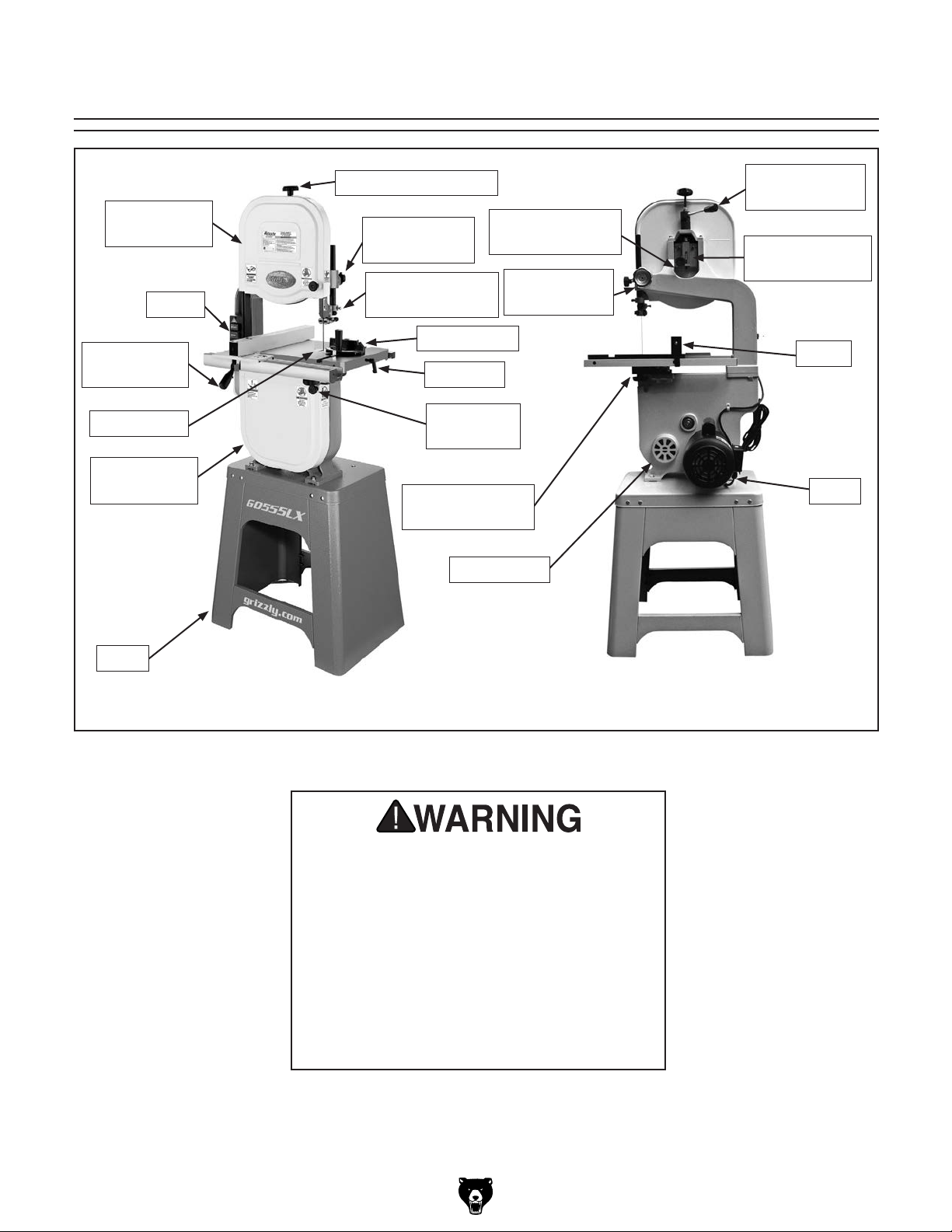
Identification
Upper Wheel
Guard
Switch
Fence Lock
Handle
Table Insert
Lower Wheel
Guard
Blade Tension Knob
Guide Post
Control Knob
Upper Blade
Guide Assembly
Miter Gauge
Table Pin
Table Tilt
Lock Knob
Lower Blade
Guide Assembly
4" Dust Port
Blade Tracking
Knob
Guide Post
Control Knob
Blade Quick
Release Lever
Blade Tension
Scale
Fence
Motor
Stand
Figure 1. G0555LX identification.
For Your Own Safety, Read Instruction
Manual Before Operating Bandsaw
a) Wear eye protection.
b) Do not remove jammed cutoff pieces
until blade has stopped.
c) Maintain proper adjustment of blade
tension, blade guides, and thrust
bearings.
d) Adjust upper guide to just clear
workpiece.
e) Hold workpiece firmly against table.
G0555LX (Mfg. Since 3/13)
-3-
Page 6

Machine Data Sheet
MACHINE DATA
SHEET
Customer Service #: (570) 546-9663 · To Order Call: (800) 523-4777 · Fax #: (800) 438-5901
MODEL G0555LX 14" DELUXE BANDSAW
Product Dimensions:
Weight.............................................................................................................................................................. 229 lbs.
Width (side-to-side) x Depth (front-to-back) x Height..................................................................... 27 x 30 x 67-1/2 in.
Footprint (Length x Width)............................................................................................................... 23-1/2 x 16-1/2 in.
Shipping Dimensions:
Carton #1
Type........................................................................................................................................... Cardboard Box
Content................................................................................................................................................. Machine
Weight.................................................................................................................................................... 204 lbs.
Length x Width x Height............................................................................................................. 45 x 22 x 18 in.
Must Ship Upright......................................................................................................................................... N/A
Carton #2
Type........................................................................................................................................... Cardboard Box
Content...................................................................................................................................................... Stand
Weight...................................................................................................................................................... 42 lbs.
Length x Width x Height................................................................................................................... 0 x 0 x 0 in.
Must Ship Upright......................................................................................................................................... N/A
Electrical:
Power Requirement............................................................................................. 110V or 220V, Single-Phase, 60 Hz
Prewired Voltage.................................................................................................................................................. 110V
Full-Load Current Rating.................................................................................................... 11A at 110V, 5.5A at 220V
Minimum Circuit Size.......................................................................................................... 15A at 110V, 15A at 220V
Connection Type....................................................................................................................................... Cord & Plug
Power Cord Included.............................................................................................................................................. Yes
Power Cord Length............................................................................................................................................... 10 ft.
Power Cord Gauge......................................................................................................................................... 16 AWG
Plug Included.......................................................................................................................................................... Yes
Included Plug Type................................................................................................................................. 5-15 for 110V
Recommended Plug Type...................................................................................................................... 6-15 for 220V
Switch Type................................................................................................... ON/OFF Push Button Switch w/Padlock
-4-
Motors:
Main
Type................................................................................................................. TEFC Capacitor-Start Induction
Horsepower................................................................................................................................................ 1 HP
Phase............................................................................................................................................ Single-Phase
Amps.................................................................................................................................................... 11A/5.5A
Speed................................................................................................................................................ 1725 RPM
Power Transfer .................................................................................................................................. Belt Drive
Bearings..................................................................................................... Shielded & Permanently Lubricated
G0555LX (Mfg. Since 3/13)
Page 7

Main Specifications:
Main Specifications
Bandsaw Size............................................................................................................................................ 14 in.
Max Cutting Width (Left of Blade)........................................................................................................ 13-1/2 in.
Max Cutting Width (Left of Blade) w/Fence......................................................................................... 11-7/8 in.
Max Cutting Height (Resaw Height)............................................................................................................ 6 in.
Blade Speeds........................................................................................................................... 1800, 3100 FPM
Blade Information
Standard Blade Length........................................................................................................................ 93-1/2 in.
Blade Length Range.............................................................................................................. 92-1/2 – 93-1/2 in.
Blade Width Range.......................................................................................................................... 1/8 – 3/4 in.
Type of Blade Guides...................................................................................................................... Ball Bearing
Guide Post Adjustment Type.................................................................................................................. Manual
Has Quick-Release...................................................................................................................................... Yes
Table Information
Table Length.............................................................................................................................................. 14 in.
Table Width................................................................................................................................................ 14 in.
Table Thickness.................................................................................................................................... 1-1/2 in.
Table Tilt.......................................................................................................................... Left 10, Right 45 deg.
Table Tilt Adjustment Type..................................................................................................................... Manual
Floor-to-Table Height................................................................................................................................. 43 in.
Fence Locking Position.............................................................................................................................. Front
Fence is Adjustable for Blade Lead.............................................................................................................. Yes
Resaw Fence Attachment Included............................................................................................................... No
Miter Gauge Included................................................................................................................................... Yes
Construction Materials
Table....................................................................................................................... Precision Ground Cast Iron
Trunnion............................................................................................................................................. Aluminum
Fence............................................................................................................ Extruded Aluminum and Cast Iron
Base/Stand............................................................................................................................. Pre-Formed Steel
Frame/Body......................................................................................................................................... Cast Iron
Wheels................................................................................................................ Computer-Balanced Cast Iron
Tire.......................................................................................................................................................... Rubber
Wheel Cover ......................................................................................................................... Pre-Formed Steel
Paint................................................................................................................................ Powder Coating & Ure
Other Related Information
Wheel Diameter................................................................................................................................... 13-3/4 in.
Wheel Width........................................................................................................................................ 1-3/16 in.
Number of Dust Ports....................................................................................................................................... 1
Dust Port Size.............................................................................................................................................. 4 in.
Compatible Mobile Base.......................................................................................................................... D3757
Other Specifications:
Country Of Origin ............................................................................................................................................. Taiwan
Warranty ........................................................................................................................................................... 1 Year
Approximate Assembly & Setup Time ...................................................................................................... 1-1/2 Hours
Serial Number Location ........................................................................................................... ID Label on Top Cover
ISO 9001 Factory .................................................................................................................................................... No
CSA Certified ......................................................................................................................................................... Yes
G0555LX (Mfg. Since 3/13)
-5-
Page 8

SECTION 1: SAFETY
For Your Own Safety, Read Instruction
Manual Before Operating This Machine
The purpose of safety symbols is to attract your attention to possible hazardous conditions.
This manual uses a series of symbols and signal words intended to convey the level of importance of the safety messages. The progression of symbols is described below. Remember that
safety messages by themselves do not eliminate danger and are not a substitute for proper
accident prevention measures. Always use common sense and good judgment.
Indicates an imminently hazardous situation which, if not avoided,
WILL result in death or serious injury.
Indicates a potentially hazardous situation which, if not avoided,
COULD result in death or serious injury.
Indicates a potentially hazardous situation which, if not avoided,
MAY result in minor or moderate injury. It may also be used to alert
against unsafe practices.
This symbol is used to alert the user to useful information about
NOTICE
proper operation of the machine.
Safety Instructions for Machinery
OWNER’S MANUAL. Read and understand this
owner’s manual BEFORE using machine.
TRAINED OPERATORS ONLY. Untrained operators have a higher risk of being hurt or killed.
Only allow trained/supervised people to use this
machine. When machine is not being used, disconnect power, remove switch keys, or lock-out
machine to prevent unauthorized use—especially
around children. Make workshop kid proof!
DANGEROUS ENVIRONMENTS. Do not use
machinery in areas that are wet, cluttered, or have
poor lighting. Operating machinery in these areas
greatly increases the risk of accidents and injury.
MENTAL ALERTNESS REQUIRED. Full mental
alertness is required for safe operation of machinery. Never operate under the influence of drugs or
alcohol, when tired, or when distracted.
ELECTRICAL EQUIPMENT INJURY RISKS. You
can be shocked, burned, or killed by touching live
electrical components or improperly grounded
machinery. To reduce this risk, only allow qualified
service personnel to do electrical installation or
repair work, and always disconnect power before
accessing or exposing electrical equipment.
DISCONNECT POWER FIRST.
nect machine from power supply BEFORE making
adjustments, changing tooling, or servicing machine.
This prevents an injury risk from unintended startup
or contact with live electrical components.
EYE PROTECTION. Always wear ANSI-approved
safety glasses or a face shield when operating or
observing machinery to reduce the risk of eye
injury or blindness from flying particles. Everyday
eyeglasses are not approved safety glasses.
Always discon-
-6-
G0555LX (Mfg. Since 3/13)
Page 9

WEARING PROPER APPAREL. Do not wear
clothing, apparel or jewelry that can become
entangled in moving parts. Always tie back or
coverlong hair. Wearnon-slip footwear to avoid
accidentalslips,whichcouldcause lossofworkpiececontrol.
hAzARdOus dusT. Dust created while using
machinery may cause cancer, birth defects, or
long-term respiratory damage. Be aware of dust
hazardsassociatedwitheachworkpiecematerial,
andalwayswearaNIOSH-approvedrespiratorto
reduceyourrisk.
hEARING PROTECTION. Always wear hearing protection when operating or observing loud
machinery. Extended exposure to this noise
withouthearing protection can cause permanent
hearingloss.
REMOVE AdJusTING TOOLs. Tools left on
machinery can become dangerous projectiles
uponstartup.Neverleavechuckkeys,wrenches,
or any other tools on machine. Always verify
removalbeforestarting!
INTENdEd usAGE. Only use machine for its
intendedpurposeand nevermake modifications
not approved by Grizzly. Modifying machine or
using it differently than intended may result in
malfunctionormechanicalfailurethatcanleadto
seriouspersonalinjuryordeath!
AWKWARd POsITIONs. Keep proper footing
andbalanceatalltimeswhenoperatingmachine.
Donotoverreach!Avoidawkwardhandpositions
that make workpiece control difficult or increase
the
riskofaccidentalinjury.
ChILdREN & BYsTANdERs. Keepchildrenand
bystandersatasafedistancefromtheworkarea.
Stopusingmachineiftheybecomeadistraction.
FORCING MAChINERY.Donot forcemachine.
Itwill do the job safer and better at the rate for
whichitwasdesigned.
NEVER sTANd ON MAChINE. Serious injury
may occur if machine is tipped or if the cutting
toolisunintentionallycontacted.
sTABLE MAChINE. Unexpectedmovementduring operation greatly increases risk of injury or
lossofcontrol.Beforestarting,verify machineis
stableandmobilebase(ifused)islocked.
usE RECOMMENdEd ACCEssORIEs.Consult
thisowner’smanualorthemanufacturerforrecommended accessories. Using improper accessorieswillincreasetheriskofseriousinjury.
uNATTENdEd OPERATION. To reduce the
risk of accidental injury, turn machine off and
ensure all moving parts completely stop before
walking away. Never leave machine running
whileunattended.
MAINTAIN WITh CARE.Followallmaintenance
instructions and lubrication schedules to keep
machine in good working condition. A machine
that is improperly maintained could malfunction,
leading
ChECK dAMAGEd PARTs. Regularly inspect
machine for any condition that may affect safe
operation.Immediatelyrepairorreplacedamaged
ormis-adjustedpartsbeforeoperatingmachine.
MAINTAIN POWER CORds. When disconnecting cord-connected machines from power, grab
andpulltheplug—NOTthecord.Pullingthecord
may damage the wires inside. Do not handle
cord/plugwithwethands.Avoidcorddamage by
keepingitawayfromheatedsurfaces,hightraffic
areas,harshchemicals,andwet/damplocations.
toseriouspersonalinjuryordeath.
GuARds & COVERs.Guardsandcoversreduce
accidental contact with moving parts or flying
debris. Make sure they are properly installed,
undamaged,andworkingcorrectly.
G0555LX (Mfg. Since 3/13)
EXPERIENCING dIFFICuLT IEs. If at any time
youexperiencedifficulties performingthe intendedoperation,stopusingthemachine!Contactour
TechnicalSupportat(570)546-9663.
-7-
Page 10
Additional Safety for Bandsaws
BLADE CONDITION. Do not operate with dull,
cracked or badly worn blade. Dull blades require
more effort to perform the cut. Inspect blades for
cracks and missing teeth before each use.
HAND PLACEMENT. Never position fingers or
hands in line with the blade. If the workpiece or
your hands slip, serious personal injury could
occur.
WORKPIECE MATERIAL. This machine is
intended for cutting natural and man-made wood
products, and laminate covered wood products.
This machine is NOT designed to cut metal, glass,
stone, tile, etc.
BLADE REPLACEMENT. To avoid mishaps that
could result in operator injury, make sure the blade
teeth face down toward the table and the blade is
properly tensioned and tracked before operating.
BLADE SPEED. Moving the workpiece against
a blade that is not at full speed could cause kickback. Always allow the blade to come to full speed
before starting the cut.
CUTTING TECHNIQUES. Plan your cuts so you
always cut out of the wood. DO NOT back the
workpiece away from the blade while the saw is
running. If you need to back the work out, turn the
bandsaw OFF and wait for the blade to come to a
complete stop, and DO NOT twist or put excessive
stress on the blade while backing the work away.
LEAVING WORK AREA. Never leave a machine
running unattended. Allow the bandsaw to come
to a complete stop and use the padlock to disable
the machine before you leave it unattended.
FEED RATE. To avoid the risk of the workpiece
slipping and causing operator injury, always feed
stock evenly and smoothly. DO NOT force or twist
the blade while cutting, especially when sawing
small curves.
SMALL WORKPIECE HANDLING. Always support/feed the workpiece with push sticks, jig, vise,
or some type of clamping fixture. If your hands
slip during a cut while holding small workpieces
with your fingers, amputation or laceration injuries
could occur.
GUARDS. The blade guard protects the operator
from the moving bandsaw blade. ONLY operate
this bandsaw with the blade guard installed.
Like all machinery there is potential danger
when operating this machine. Accidents
are frequently caused by lack of familiarity
or failure to pay attention. Use this machine
with respect and caution to decrease the
risk of operator injury. If normal safety precautions are overlooked or ignored, serious personal injury may occur.
BLADE CONTROL. To avoid serious personal
injury, DO NOT attempt to stop or slow the blade
with your hand or the workpiece. Allow the blade
to stop on its own.
No list of safety guidelines can be complete. Every shop environment is different.
Always consider safety first, as it applies
to your individual working conditions. Use
this and other machinery with caution and
respect. Failure to do so could result in
serious personal injury, damage to equipment, or poor work results.
-8-
G0555LX (Mfg. Since 3/13)
Page 11

SECTION 2: POWER SUPPLY
Before installing the machine, consider the availability and proximity of the required power supply
circuit. If an existing circuit does not meet the
requirements for this machine, a new circuit must
be installed. To minimize the risk of electrocution,
fire, or equipment damage, installation work and
electrical wiring must be done by an electrican or
qualified service personnel in accordance with all
applicable codes and standards.
Electrocution, fire, or
equipment damage may
occur if machine is not
correctly grounded and
connected to the power
The full-load current rating is the amperage a
machine draws at 100% of the rated output power.
On machines with multiple motors, this is the
amperage drawn by the largest motor or sum of all
motors and electrical devices that might operate
at one time during normal operations.
The full-load current is not the maximum amount
of amps that the machine will draw. If the machine
is overloaded, it will draw additional amps beyond
the full-load rating.
If the machine is overloaded for a sufficient length
of time, damage, overheating, or fire may result—
especially if connected to an undersized circuit.
To reduce the risk of these hazards, avoid overloading the machine during operation and make
sure it is connected to a power supply circuit that
meets the requirements in the following section.
For your own safety and protection of
A power supply circuit includes all electrical
equipment between the breaker box or fuse panel
in the building and the machine. The power supply circuit used for this machine must be sized to
safely handle the full-load current drawn from the
machine for an extended period of time. (If this
machine is connected to a circuit protected by
fuses, use a time delay fuse marked D.)
Note: The circuit requirements listed in this manual apply to a dedicated circuit—where only one
machine will be running at a time. If this machine
will be connected to a shared circuit where multiple machines will be running at the same time,
consult a qualified electrician to ensure that the
circuit is properly sized for safe operation.
This machine can be converted to operate on a
220V power supply (refer to Voltage Conversion
instructions). This power supply must have a verified ground and meet the following requirements:
This machine is prewired to operate on a 110V
power supply circuit that has a verified ground and
meets the following requirements:
Availability
supply.
Full-Load Current Rating
Circuit Information
property, consult an electrician if you are
unsure about wiring practices or electrical
codes in your area.
Full-Load Current Rating at 110V ...... 11 Amps
Full-Load Current Rating at 220V .... 5.5 Amps
G0555LX (Mfg. Since 3/13)
Circuit Requirements for 110V
Nominal Voltage ...............................110V/120V
Cycle .......................................................... 60 Hz
Phase ........................................... Single-Phase
Circuit Rating ...................................... 15 Amps
Plug/Receptacle ............................. NEMA 5-15
Circuit Requirements for 220V
Nominal Voltage .............................. 220V/240V
Cycle .......................................................... 60 Hz
Phase ........................................... Single-Phase
Circuit Rating ...................................... 15 Amps
Plug/Receptacle ............................. NEMA 6-15
-9-
Page 12
Improper connection of the equipment-grounding
wire can result in a risk of electric shock. The
wire with green insulation (with or without yellow
stripes) is the equipment-grounding wire. If repair
or replacement of the power cord or plug is necessary, do not connect the equipment-grounding
wire to a live (current carrying) terminal.
Check with a qualified electrician or service personnel if you do not understand these grounding
requirements, or if you are in doubt about whether
the tool is properly grounded. If you ever notice
that a cord or plug is damaged or worn, disconnect it from power, and immediately replace it with
a new one.
Grounding Requirements
This machine MUST be grounded. In the event
of certain malfunctions or breakdowns, grounding
reduces the risk of electric shock by providing a
path of least resistance for electric current.
Serious injury could occur if you connect
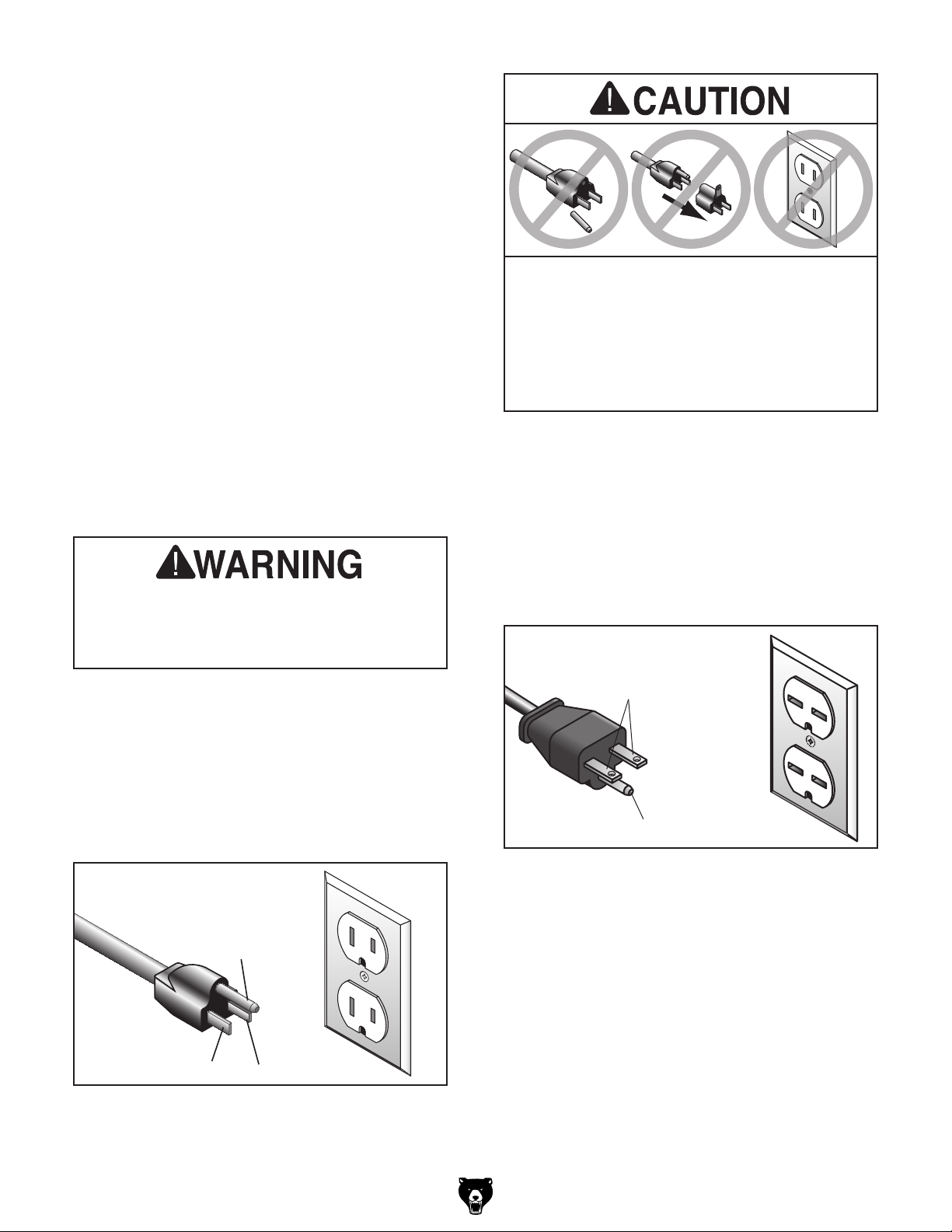
For 110V operation: This machine is equipped
with a power cord that has an equipment-grounding wire and a grounding plug (see following figure). The plug must only be inserted into a matching receptacle (outlet) that is properly installed
and grounded in accordance with all local codes
and ordinances.
For 220V operation: The plug specified under
“
page has a grounding prong that must be attached
to the equipment-grounding wire on the included
power cord. The plug must only be inserted into
a matching receptacle (see following figure) that
is properly installed and grounded in accordance
with all local codes and ordinances.
it will not fit the outlet, have a qualified
SHOCK HAZARD!
Two-prong outlets do not meet the grounding
requirements for this machine. Do not modify
or use an adapter on the plug provided—if
electrician install the proper outlet with a
verified ground.
Circuit Requirements for 220V” on the previous
the machine to power before completing the
setup process. DO NOT connect to power
until instructed later in this manual.
GROUNDED
5-15 RECEPTACLE
Grounding Prong
5-15 PLUG
Neutral Hot
Figure 2. Typical 5-15 plug and receptacle.
-10 -
GROUNDED
6-15 RECEPTACLE
Current Carrying Prongs
6-15 PLUG
Grounding Prong
Figure 3. Typical 6-15 plug and receptacle.
G0555LX (Mfg. Since 3/13)
Page 13
Extension Cords
We do not recommend using an extension cord
with this machine.
cord, only use it if absolutely necessary and only
on a temporary basis.
Extension cords cause voltage drop, which may
damage electrical components and shorten motor
life. Voltage drop increases as the extension cord
size gets longer and the gauge size gets smaller
(higher gauge numbers indicate smaller sizes).
Any extension cord used with this machine must
contain a ground wire, match the required plug
and receptacle, and meet the following requirements:
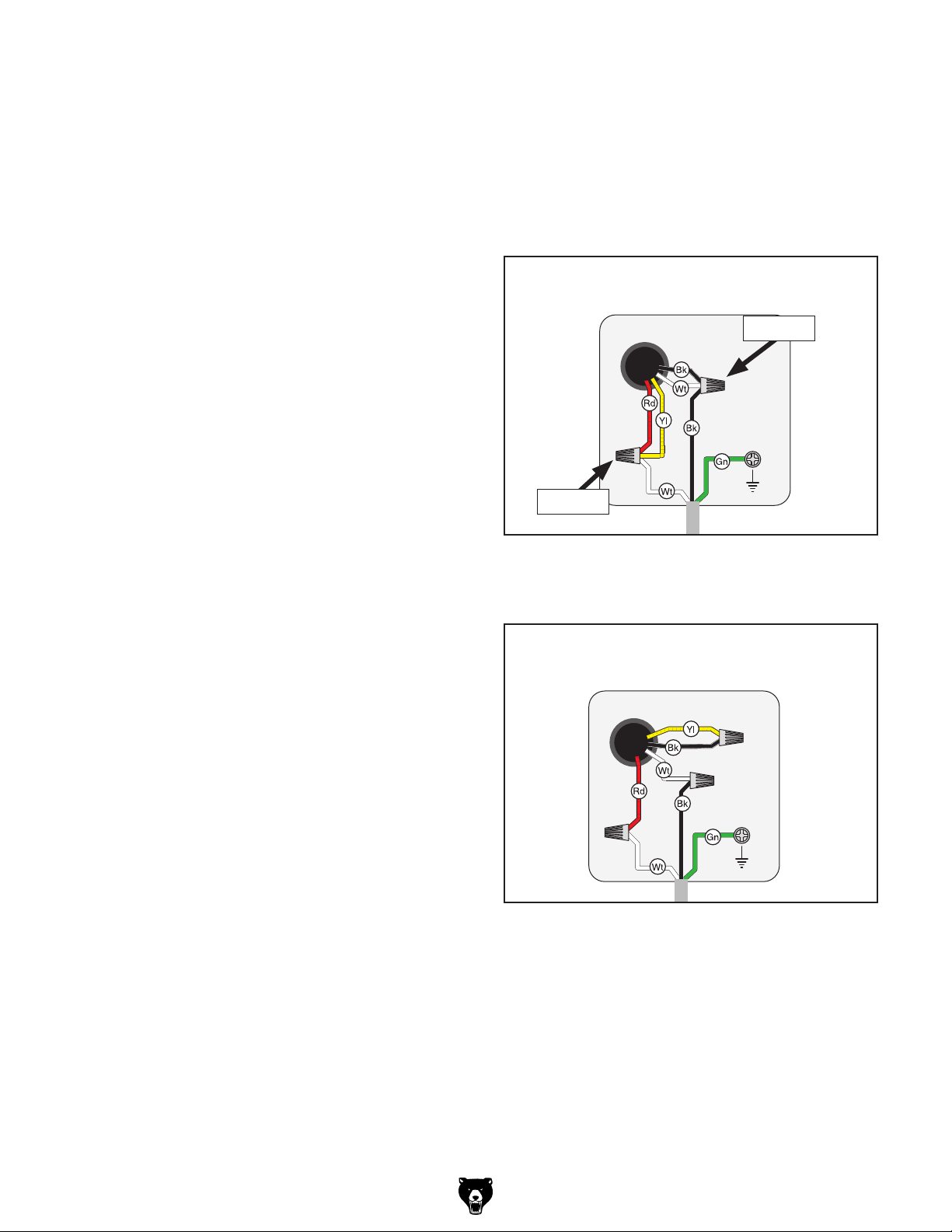
Motor
Ground
Motor
Pre-wired
for 110V
To convert the machine to 220V:
Minimum Gauge Size ...........................14 AWG
Maximum Length (Shorter is Better).......50 ft.
Voltage Conversion
The voltage conversion MUST be performed by
an electrician or a qualified service personnel. The
voltage conversion is a two step process involving
rewiring the motor for the new voltage and installing a new plug according to the manufacturer's
instructions.
Note: If the diagram included on the motor conflicts with the one in this manual, the motor may
have changed since the manual was printed. If
this is the case, use the diagram provided inside
the motor wiring junction box instead of the one
provided in this manual.
If you must use an extension
1. DISCONNECT MACHINE FROM POWER!
2. Remove the 5-15 plug from the cord.
3. Remove the two wire nuts from the wires
shown in Figure 4.
Pre-wired
for 110V
Remove
Ground
Remove
Figure 4. Motor pre-wired for 110V.
4. Re-wire the motor as shown in Figure 4.
Motor
Rewired
for 220V
Items Needed: Qty
Wire Nut 14 AWG ............................................. 1
Electrical Tape ................................... As Needed
Nema 6-15 Plug ................................................. 1
G0555LX (Mfg. Since 3/13)
Ground
Figure 5. Motor rewired for 220V.
5. Tighten all wire nuts and secure them with
electrical tape so they cannot vibrate loose
during motor operation.
6. Install the 6-15 plug on the power cord per
the plug manufacturer's instructions.
-11-
Page 14
SECTION 3: SET UP
Keep children and pets away
from plastic bags or packing
materials shipped with this
Set Up Safety
This machine presents
serious injury hazards
to untrained users. Read
through this entire manual to become familiar with
the controls and operations before starting the
machine!
Wear safety glasses during the entire set up process!
This machine and its components are very heavy.
Get lifting help or use
power lifting equipment
such as a forklift to move
heavy items.
Needed for Setup
The following are needed to complete the setup
process, but are not included with your machine.
Description Qty
• Additional People ....................... As Needed
• Safety Glasses ........................................... 1
• Disposable Shop Rags ............... As Needed
• Cleaner/Degreaser ..................... As Needed
• Level ........................................................... 1
• Hex Wrench 5mm ....................................... 1
• Wrench or Socket 10mm ............................ 2
• Wrench or Socket 13mm ............................ 2
Unpacking
Your machine was carefully packaged for safe
transportation. Remove the packaging materials
from around your machine and inspect it. If you
discover the machine is damaged, please imme-
diately call us at (570) 546-9663 for advice.
Save the containers and all packing materials for
possible inspection by the carrier or its agent.
Otherwise, filing a freight claim can be difficult.
-12-
When you are completely satisfied with the condition of your shipment, inventory the contents.
SUFFOCATION HAZARD!
machine. Discard immediately.
G0555LX (Mfg. Since 3/13)
Page 15
Inventory
The following is a list of items shipped with your
machine. Before beginning setup, lay these items
out and inventory them.
If any non-proprietary parts are missing (e.g. a
nut or a washer), we will gladly replace them; or
for the sake of expediency, replacements can be
obtained at your local hardware store.
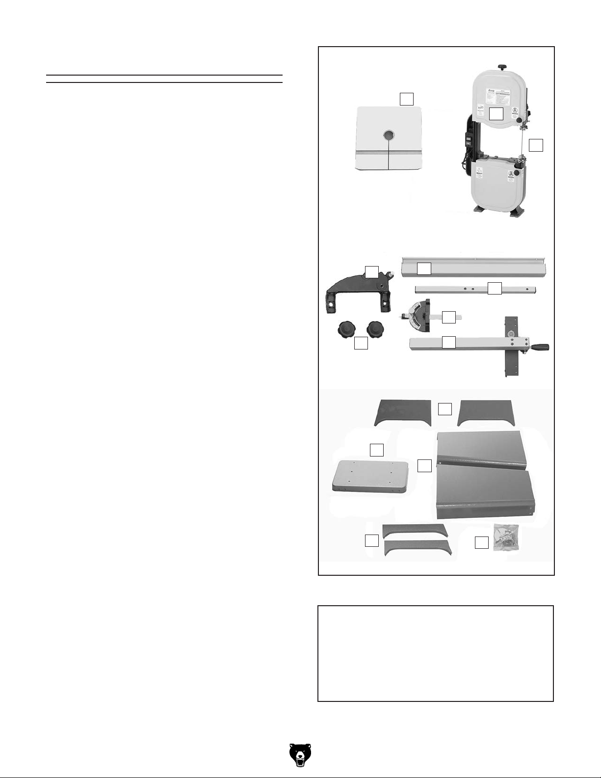
Inventory (see Figure 6) Qty
A. Table .......................................................... 1
B. Saw Blade 93
C. Bandsaw Body ........................................... 2
D. Trunnion Base ............................................ 1
E. Front Fence Rail ......................................... 1
F. Rear Fence Rail ......................................... 1
G. Miter Gauge Assembly ............................... 1
H. Fence Assembly ......................................... 1
I. Trunnion Lock Knobs.................................. 2
J. Upper Stand Braces ................................... 2
K. Sta nd To p ................................................... 1
L. Stand Sides ................................................ 2
M. Lower Stand Braces ................................... 2
N. Hardware Bag ............................................ 1
—Table Insert ............................................. 1
—Hex Bolts
—Hex Nuts
—Lock Washers
—Flat Washers
—Cap Screws
—Hex Bolts
—Flat Washers
—Hex Bolts
—Flat Washers
—Flange Nuts (Stand).............................. 16
—Stand Feet
—Carriage Bolts
—Flange Nuts
—Hex Nuts
—Flat Washer
—Combo Wrench 10 x 12mm .................... 1
—Hex Wrench 5mm ................................... 1
1
⁄2 " x 3⁄8" x 6 TPI ................... 1
5
⁄16"-18 x 1 1⁄2 " (Bandsaw) ........ 4
5
⁄16"-18 (Bandsaw) ................... 4
5
⁄16" (Bandsaw) ................ 4
5
⁄16" (Bandsaw) .................. 8
1
⁄4"-20 x 5⁄8" (Fence) ............ 2
1
⁄4"-20 x 3⁄4" (Fence) ................ 2
1
⁄4" (Fence) ........................ 2
1
⁄4"-20 x 5⁄8" (Stand) .............. 16
1
⁄4" (Stand)....................... 16
3
⁄8"-16 x 2" (Stand) ................ 4
5
⁄16"-18 x 5⁄8" (Stand) ........ 8
5
⁄16"-18 (St and) .................... 8
3
⁄8"-16 (Stand Feet) .................. 8
3
⁄8" (Stand Feet) .................. 8
A
C
B
D
E
F
G
I
H
J
K
L
M
N
Figure 6. Main components inventory.
NOTICE
If you cannot find an item on this list, carefully check around/inside the machine and
packaging materials. Often, these items get
lost in packaging materials while unpacking or they are pre-installed at the factory.
G0555LX (Mfg. Since 3/13)
-13-
Page 16
The unpainted surfaces of your machine are
coated with a heavy-duty rust preventative that
prevents corrosion during shipment and storage.
This rust preventative works extremely well, but it
will take a little time to clean.
Be patient and do a thorough job cleaning your
machine. The time you spend doing this now will
give you a better appreciation for the proper care
of your machine's unpainted surfaces.
There are many ways to remove this rust preven
tative, but the following steps work well in a wide
variety of situations. Always follow the manufac
turer’s instructions with any cleaning product you
use and make sure you work in a well-ventilated
area to minimize exposure to toxic fumes.
Before cleaning, gather the following:
•
•
•
•
Basic steps for removing rust preventative:
1.
2.
3.
4.
metal protectant to prevent rust.
Gasoline or products
Many cleaning solvents
ed amounts are inhaled.
Avoid chlorine-based solvents, such as
Cleanup
with low flash points can
explode or cause fire if
used to clean machinery. Avoid cleaning with
these products.
are toxic if concentrat-
Disposable Rags
Cleaner/degreaser (WD•40 works well)
Safety glasses & disposable gloves
Plastic paint scraper (optional)
Put on safety glasses.
Coat the rust preventative with a liberal
amount of cleaner/degreaser, then let it soak
for 5–10 minutes.
Wipe off the surfaces. If your cleaner/degreas-
er is effective, the rust preventative will wipe
off easily. If you have a plastic paint scraper,
scrape off as much as you can first, then wipe
off the rest with the rag.
-
-
Only work in a well-ventilated area.
NOTICE
acetone or brake parts cleaner, that may
damage painted surfaces. Test all cleaners
in an inconspicuous area before using to
make sure they will not damage paint.
Repeat Steps 2–3 as necessary until clean,
then coat all unpainted surfaces with a quality
-14-
G0555LX (Mfg. Since 3/13)
Page 17
Site Considerations
Weight Load
Physical Environment
Place this machine near an existing power source.
Shadows, glare, or strobe effects that may distract
Refer to the Machine Data Sheet for the weight
of your machine. Make sure that the surface upon
which the machine is placed will bear the weight
of the machine, additional equipment that may be
installed on the machine, and the heaviest workpiece that will be used. Additionally, consider the
weight of the operator and any dynamic loading
that may occur when operating the machine.
Space Allocation
Consider the largest size of workpiece that will
be processed through this machine and provide
enough space around the machine for adequate
operator material handling or the installation of
auxiliary equipment. With permanent installations,
leave enough space around the machine to open
or remove doors/covers as required by the maintenance and service described in this manual.
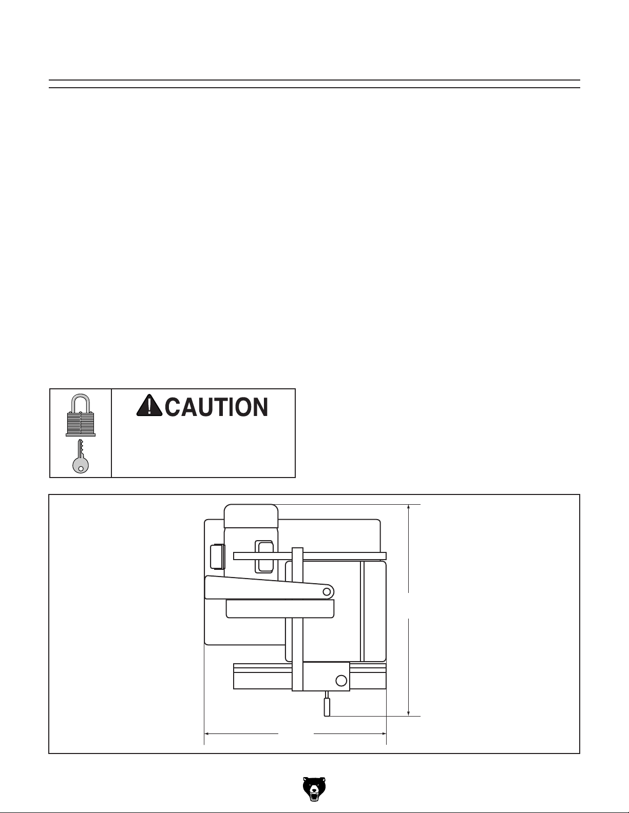
See below for required space allocation.
Children or untrained people
may be seriously injured by
this machine. Only install in an
access restricted location.
The physical environment where the machine is
operated is important for safe operation and longevity of machine components. For best results,
operate this machine in a dry environment that is
free from excessive moisture, hazardous chemicals, airborne abrasives, or extreme conditions.
Extreme conditions for this type of machinery are
generally those where the ambient temperature
range exceeds 41°–104°F; the relative humidity
range exceeds 20–95% (non-condensing); or the
environment is subject to vibration, shocks, or
bumps.
Electrical Installation
Make sure all power cords are protected from
traffic, material handling, moisture, chemicals,
or other hazards. Make sure to leave access to
a means of disconnecting the power source or
engaging a lockout/tagout device, if required.
Lighting
Lighting around the machine must be adequate
enough that operations can be performed safely.
or impede the operator must be eliminated.
G0555LX (Mfg. Since 3/13)
30"
27"
Figure 7. Minimum working clearances.
-15-
Page 18
Assembly
Some sheet metal parts
may have sharp edges
that can cause minor cuts.
Please use care while handling them.
The bandsaw is heavy and awkward to lift
onto the stand. Get assistance from another
person when lifting.
2. Attach the remaining stand side to the assem-
1
bly, as shown in Figure 9, with (8)
1
hex bolts, (8)
⁄4" flat washers, and (8) 1⁄4"-20
⁄4"-20 x 5⁄8"
flange nuts.
To assemble the bandsaw:
1. Lay one stand side flat on a piece of card-
board to prevent scratching the paint, then
attach the upper and lower stand braces
to one side, as shown in Figure 8, with (8)
1
⁄4"-20 x 5⁄8" hex bolts, (8) 1⁄4" flat washers, and
1
⁄4"-20 flange nuts.
(8)
Note: Only hand-tighten the stand fasteners
during these initial steps. Once the stand is
completely assembled you will be instructed
to fully tighten all fasteners.
Upper
Stand Brace
Lower
Stand Brace
x 8
Figure 9. Second stand side attached.
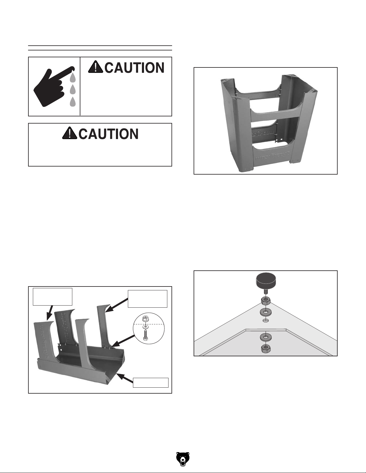
3. Install the stand feet, as shown in Figure 10,
in the bottom of the stand assembly, using
3
⁄8"-16 x 2" stand foot, (2) 3⁄8"-16 hex nuts
a
and (2)
3
⁄8" flat washers on each foot in the
sequence shown.
Note: Adjust the feet so that they are approxi-
mately the same height—this will make leveling the stand easier in a later step.
Foot
Hex Nut
Flat
Washer
Flat
Washer
Hex Nut
Figure 8. Upper and lower stand braces
attached to the stand side.
-16 -
Figure 10. Stand foot installed (1 of 4).
Stand Side
G0555LX (Mfg. Since 3/13)
Page 19
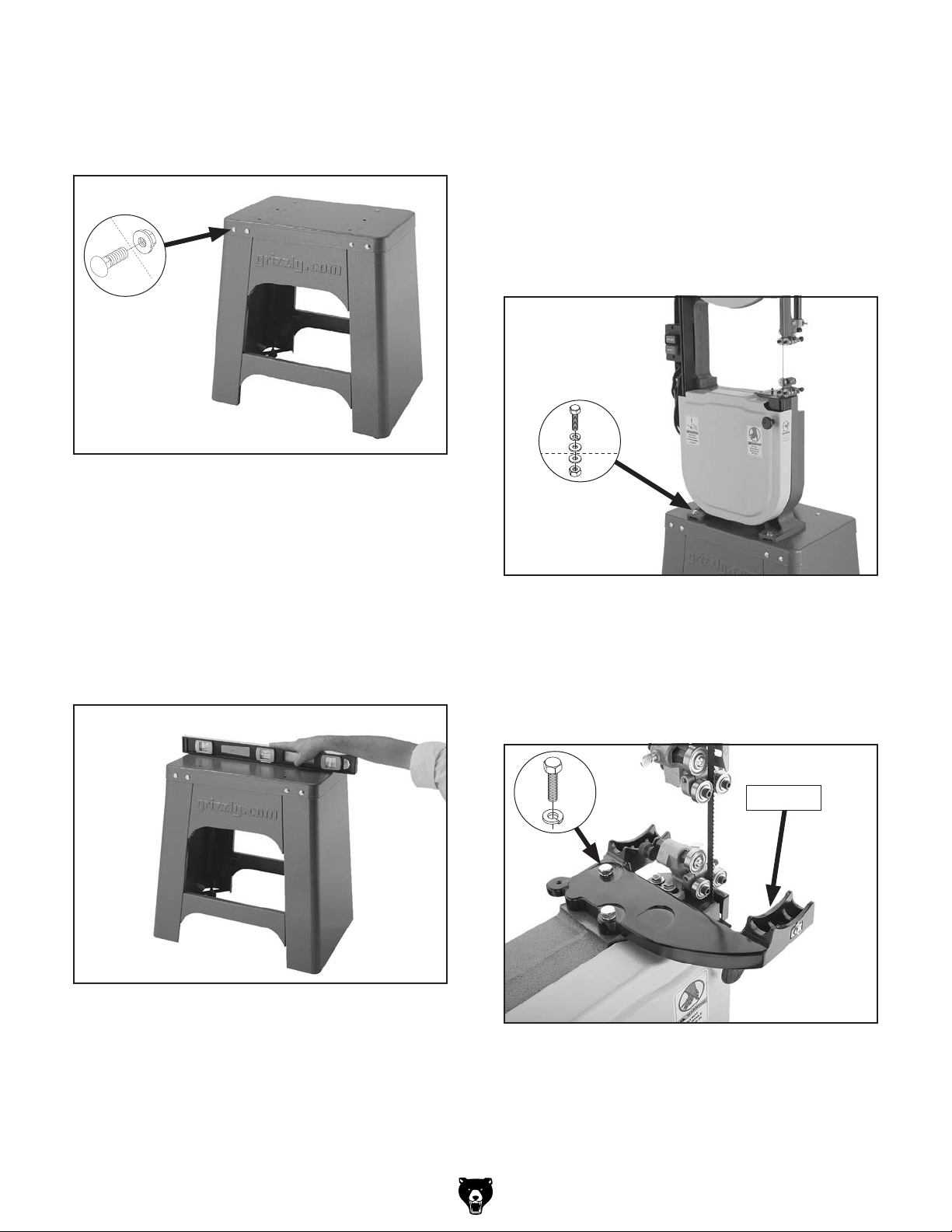
4. Turn the stand assembly upright and attach
5
the top, as shown in Figure 11, with (8)
5
⁄8" carriage bolts and (8) 5⁄16"-18 flange
18 x
⁄16"-
nuts.
7. With the help of other people, lift the bandsaw
assembly onto the stand and align the mounting holes. Have one person hold the bandsaw
in place to keep it from fall until you can complete the next step.
x 8
Figure 11. Stand top attached.
5. Square up the stand components and fully
tighten all the fasteners.
6. Place the level on top of the stand assembly,
as shown in Figure 12, then adjust the feet
up or down to make the stand top level from
side to side and front to back. Make sure that
both hex nuts on the feet are tight against the
stand assembly so they will not move.
8. Secure the bandsaw assembly to the stand
5
with (4)
washers, (8)
⁄16"-18 x 1 1⁄2" hex bolts, (4) 5⁄16" lock
5
⁄16" flat washers, and (4) 5⁄16"-18
hex nuts, as shown in Figure 13.
x 4
Figure 13. Bandsaw assembly attached to the
stand.
9. Position the table trunnion on the bandsaw,
as shown in Figure 14, then secure it with the
5
⁄16"-18 x 1 1⁄4" hex bolts and (2) 5⁄16" lock
(2)
washers.
Figure 12. Leveling the stand.
G0555LX (Mfg. Since 3/13)
x 2
Trunnion
Figure 14. Trunnion installed.
-17-
Page 20
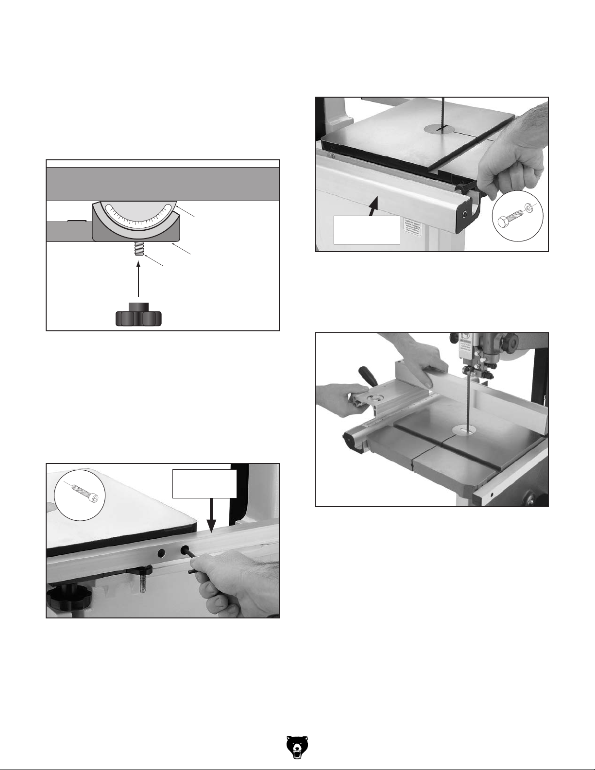
10. Line up the table slot with the blade, then
position the table so that the blade is in the
center cut-out.
11. Rotate the table so that the table slot faces to
the right, then insert the table bolts through
the mounting holes in the trunnion base, as
shown in Figure 15.
Table
14. Attach the front fence rail shown in Figure 17,
1
with (2)
⁄4"-20 x 3⁄4" hex bolts and 1⁄4" flat
washers.
Table Trunnion
Trunnion Base
Trunnion Bolt
Figure 15. Installing the table onto the trunnion
base.
12. Secure the table by fully threading the two
trunnion lock knobs onto the table bolts.
13. Attach the rear fence rail to the rear of the
table with (2) 1/4"-20 x
shown in Figure 16.
5
⁄8" cap screws, as
Rear Fence
Rail
Front Fence
Rail
x 2
Figure 17. Installing front fence rail.
15. Pull the fence handle up and place the
fence on the front fence rail, as shown in
Figure 18.
-18-
x 2
Figure 16. Installing rear fence rail.
Figure 18. Installing fence onto rails.
G0555LX (Mfg. Since 3/13)
Page 21
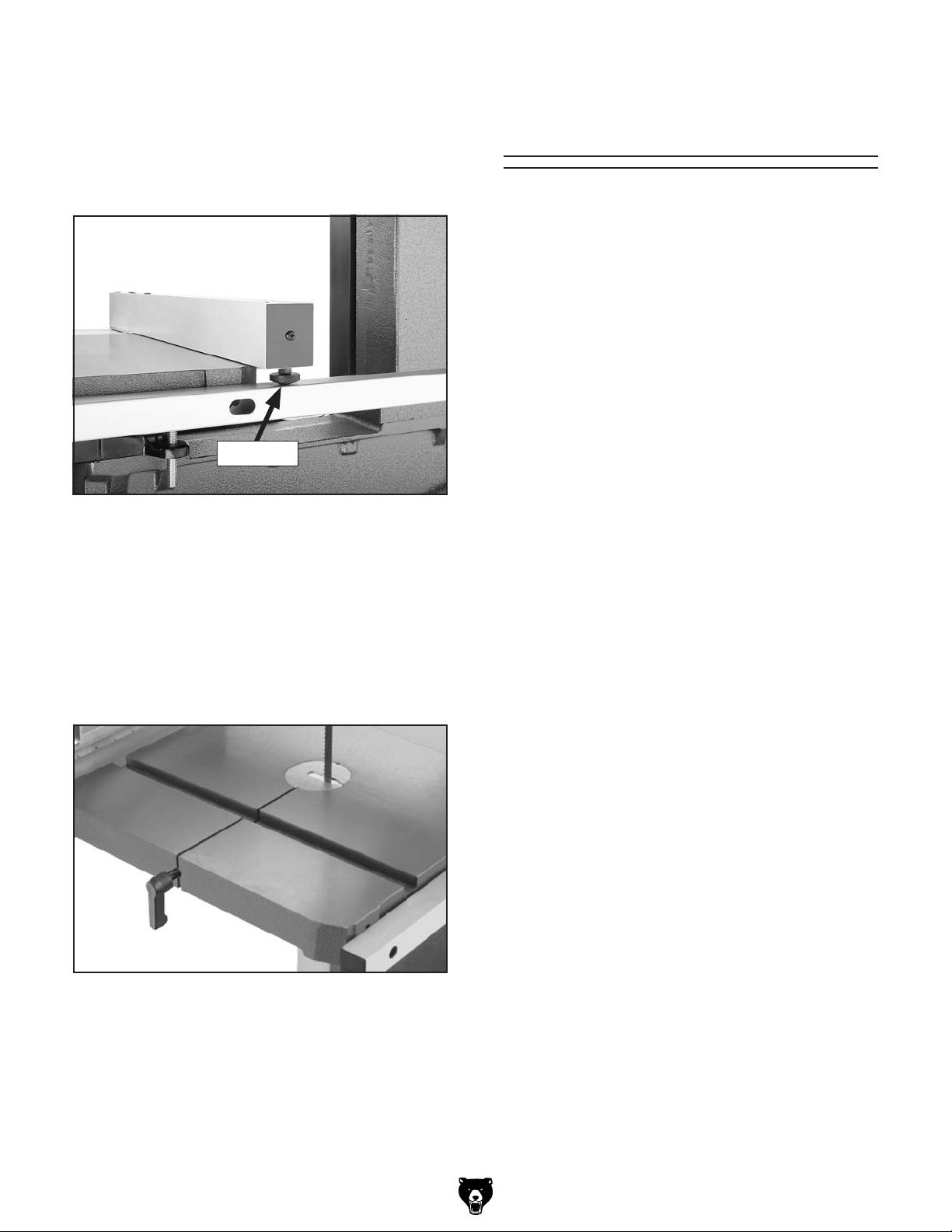
16. Thread the M6-1 hex nut onto the fence rail
pad, then thread it into the rear underside of
the fence (see Figure 19) so that the fence
rests the same height above the table along
its full length. Tighten the hex nut against the
fence to secure the setting.
Adjustment
Overview
The bandsaw is one of the most versatile woodworking machines. As such it has multiple components that must be properly adjusted for the best
cutting results.
For safety reasons some adjustments and test
operations must be performed before performing
other necessary adjustments. Below is an overview of all the adjustments and the order in which
they should be performed.
Adjustment procedures include:
Rail Pad
Figure 19. Fence rail pad installed.
17. Install the table insert and table pin, as show
in Figure 20.
Important: Make sure you re-install the table
pin. This pin keeps the table surfaces on
either side of the slot even with the changes in operating pressures and temperature
changes.
• Blade Tracking
• Dust Collection
• Power Connection
• Test Run
• Tension Blade
• Adjusting Blade Support Bearings
• Adjusting Blade Guide Bearings
• Table Tilt Calibration
• Aligning Table
• Aligning Fence
Figure 20. Table pin and insert installed.
G0555LX (Mfg. Since 3/13)
-19 -
Page 22

Blade Tracking
"Tracking" refers to how the blade rides on the
bandsaw wheels. Proper tracking is important
for maintaining bandsaw adjustments, achieving correct blade tension, and cutting accurately. Improper tracking reduces cutting accuracy,
causes excess vibrations, and places stress on
the blade and other bandsaw components. The
shape of the wheels and the orientation of the
wheels in relation to each other determine how
the blade tracks.
Bandsaw wheels are either flat or crowned and
both shapes track differently. The G0555LX has
crowned wheels. As the wheels spin the blade
naturally tracks to the highest point of the crown at
the center of the wheel (see Figure 21).
PROPER TRACKING
Parallel And
Coplanar
or
Parallel But Not
Coplanar
Blade Centered
on Peak of Crown
Blade
Centered
on Wheel
Figure 21. Blade centered on the crown of the
The wheels of the bandsaw must be aligned for
the blade to track correctly on the crown of the
wheel. Properly aligned wheels are parallel and
coplanar (see Figure 22).
Improper blade tension and cutting practices can
negatively affect blade tracking. Familiarizing
yourself with the ideas and conditions described
in Figure 22 will help you recognize when your
saws wheel alignment may need adjusted (refer
to Wheel Alignment on Page 48 for detailed
instructions on adjusting the tracking).
Wheel
wheel.
Coplanar But
Not Parallel
Figure 22. Wheel alignment and misalignment
examples.
The wheels on the G0555LX were aligned at the
factory, so center tracking is the only adjustment
that needs to be performed when the saw is new.
This adjustment is necessary turning the saw on
or performing other adjustments.
Not Coplanar or
Parallel
-20-
G0555LX (Mfg. Since 3/13)
Page 23

To center track the blade:
1. DISCONNECT BANDSAW FROM POWER!
2. Adjust the upper and lower blade guides
away from the blade (refer to Adjusting
Blade Guide Bearings on Page 26 for
detailed instructions).
Note: When adjusting the blade tracking for
the test run in this procedure, the blade must
have a reasonable amount of tension to simulate operating conditions. After the test run
is successfully completed, you will perform
a thorough version of the following steps to
more accurately tension the blade.
3. Move the blade tension quick release lever all
the way right (as viewed from the rear of the
machine) to apply tension to the blade (see
Figure 23).
— If the blade rides in the center of the upper
wheel and is centered on the peak of the
wheel crown, it is properly tracking and you
are done with this procedure—proceed to
Dust Collection on Page 22.
— If the blade does is not properly tracking,
then continue with this procedure to adjust
it.
7. Loosen the wing nut on the tracking knob
(see Figure 24).
Tracking
Wing Nut
Knob
Quick Release
Tensioned for
3
⁄8" Blade
a
Figure 23. Example of tension applied for a
Lever
3
⁄8"
blade.
4. Use the tension knob on top of the bandsaw
to bring the upper edge of the indicator block
to the appropriate blade tension scale mark
for the blade width (see Figure 23).
Note: If you are using the blade that was
3
shipped with the machine, this would be
⁄8".
5. Open the upper wheel cover.
6. Rotate the upper wheel by hand several
times and watch how the blade rides on the
wheel crown (see Figure 21 on Page 19 for
an illustration of this concept).
Figure 24. Tracking knob and wing nut.
8. Spin the upper wheel with one hand and
slowly adjust the tracking knob with the other
hand until the blade consistently tracks in the
center of the wheel.
9. Tighten the wing nut to secure the setting,
then spin the upper wheel several times to
confirm the tracking. If necessary, repeat the
adjustment procedure until the blade is tracking properly.
10. Re-adjust the blade guide bearings toward
the blade (refer to Adjusting Blade Guide
Bearings on Page 26 for detailed instructions).
11. Close and secure the upper wheel cover
before operating the bandsaw.
G0555LX (Mfg. Since 3/13)
-21-
Page 24

After you have completed all previous setup
instructions and circuit requirements, the machine
is ready to be connected to the power supply.
To avoid unexpected startups or property damage, use the following steps whenever connecting
or disconnecting the machine.
1. TurnthemachinepowerswitchOFF.
2.
matching
is
1. TurnthemachinepowerswitchOFF.
2.
completely
cord
Dust Collection
Dust Collection
DO NOT operate this bandsaw without an adequate dust collection system. This bandsaw
creates substantial amounts of wood dust
while operating. Failure to use a dust collection system can result in short and long-term
respiratory illness.
Recommended CFM at Dust Port: 400 CFM
Do not confuse this CFM recommendation with
the rating of the dust collector. To determine the
CFM at the dust port, you must consider these
variables: (1) CFM rating of the dust collector,
(2) hose type and length between the dust collector and the machine, (3) number of branches
or wyes, and (4) amount of other open lines
throughout the system. Explaining how to calculate these variables is beyond the scope of
this manual. Consult an expert or purchase a
good dust collection "how-to" book.
Power Connection
Connecting Power
Insert the power cord plug into a
power supply receptacle. The machine
nowconnectedtothepowersource.
To connect a dust collection hose:
1. Fit the dust hose over the dust port, as shown
in Figure 25, and secure it in place with a
hose clamp.
2. Gently pull the hose to make sure it does not
come off. A tight fit is necessary for proper
performance.
Figure 26. Connecting power.
Disconnecting Power
Graspthemoldedplugandpullit
outofthereceptacle.Donotpullbythe
asthismaydamagethewiresinside.
Figure 25. 4" dust hose attached to dust port.
-22-
Figure 27. Disconnecting power.
G0555LX (Mfg. Since 3/13)
Page 25

Test Run
Once the assembly is complete, test run your
machine to make sure it runs properly and is
ready for regular operation.
The test run consists of verifying the following:
1) The motor powers up and runs correctly, and
2) the safety disabling mechanism on the switch
works correctly.
If, during the test run, you cannot easily locate
the source of an unusual noise or vibration, stop
using the machine immediately, then review
Troubleshooting on Page 44.
If you still cannot remedy a problem, contact our
Tech Support at (570) 546-9663 for assistance.
To test run the machine:
1. Make sure you have read the safety instruc-
tions at the beginning of the manual and that
the machine is set up properly.
Padlock
Shaft
Figure 28. Switch disabling padlock inserted into
ON button.
6. Press the ON button to test the disabling feature on the switch.
—If the machine does not start, the switch
disabling feature is working as designed.
—If the machine does start, immediately stop
it. The switch disabling feature is not working correctly. This safety feature must work
properly before proceeding with regular
operations. Call Tech Support for help.
2. Make sure all tools and objects used during
setup are cleared away from the machine.
3. Verify that the machine is operating correctly
by turning it ON.
— When operating correctly, the machine
runs smoothly with little or no vibration or
rubbing noises.
— Investigate and correct strange or unusual
noises or vibrations before operating the
machine further. Always disconnect the
machine from power when investigating or
correcting potential problems.
4. Turn the machine OFF.
5. Insert the switch disabling padlock through
the ON button, as shown in Figure 28.
Tensioning Blade
A properly tensioned blade is essential for making
accurate cuts, maximizing the life of the blade,
and making other bandsaw adjustments. However
properly tensioned blade will not compensate for
cutting problems caused by too rapid of a feed
rate, hardness variations between workpieces,
and improper blade selection.
The method used to tension the blade is often
a matter of preference. Described below are
the flutter method and the deflection method.
Either method will help safely tension the blade.
Experience and personal preference will help you
decide which method your prefer. Optimal cutting results for any workpiece are a combination
of correct blade selection, proper blade tension,
and an appropriate feed rate. Improper blade
tension is unsafe, produces inaccurate and inconsistent results, and introduces unnecessary wear
on bandsaw components. Over-tensioning the
blade increases the chance of the blade breaking
or wheel misalignment. Under-tensioned blades
wander excessively while cutting and will not track
properly during operation.
G0555LX (Mfg. Since 3/13)
-23-
Page 26

Note: Tensioning the blade according to the
blade tension scale before the Test Run was an
approximate tension. The following procedures
fine-tunes the blade tension.
The Flutter Method
1. DISCONNECT BANDSAW FROM POWER.
The Deflection Method
The deflection method is much more subjective
than the flutter method. Each blade will deflect
differently and every user will determine what
"moderate pressure" means. The following are
general guidelines for tensioning the blade with
this method.
2. Make sure the blade is properly center tracking as instructed in the Blade Tracking subsection previous on Page 19.
3. Raise the guide post all the way and move
the upper and lower guide bearings away
from the blade.
4. Engage the blade tension quick release lever
to apply tension to the blade.
5. Connect the bandsaw to power, and turn the
bandsaw ON.
6 . Using the blade tension adjustment knob,
slowly decrease blade tension until you see
the blade start to flutter.
7. Slowly increase the tension until the blade
stops fluttering, then tighten the blade tension
1
adjustment knob and additional
⁄8 to 1⁄4 of a
turn.
8. Look at what the tension gauge reads and
use that as a guide for tensioning that specific
blade in the future.
Note: Do not rely on this setting for other
blades or for long periods of time because all
blades require specific tensioning and stretch
with use. If you notice a decrease in performance at the setting repeat this procedure.
With extended use, the blade tensioning sys-
tem may need to be reset. Refer to Resetting
Blade Tensioner in the Service section in
this manual for details.
9. Disconnect the bandsaw from power.
10. Re-adjust blade guides as described in
Adjusting Blade Support Bearings and
Adjusting Blade Guide Bearings on
Pages 25– 26.
To tension the bandsaw blade:
1. DISCONNECT BANDSAW FROM POWER.
2. Make sure the blade is properly tracking as
instructed in the Blade Tracking subsection
on Page 19.
3. Raise the guide post all the way and move
the upper and lower guide bearings away
from the blade.
4. Engage the blade tension quick release lever
to apply tension to the blade.
5. Using moderate pressure, push the center of
the blade sideways.
1
—If the blade deflects approximately
⁄4" it is
properly tensioned. Proceed to Step 7.
1
—If the blade deflects less than
⁄4" it is overtensioned. Turn the blade tensioning knob
counter clockwise two full turns and repeat
Step 6.
1
—If the blade deflects
⁄4" or more, the blade
is not properly tensioned. Apply tension to
the blade incrementally and repeat Step 6
until properly tensioned.
6. Re-adjust blade guides as described in
Adjusting Blade Support Bearings and
Adjusting Blade Guide Bearings on Pages
25– 26.
When using different size blades, the blade
tensioning system may need to be reset for
correct operation. Refer to Blade Tensioner
on Page 52 for detailed instructions.
-24-
G0555LX (Mfg. Since 3/13)
Page 27

0.016''
Adjusting Blade
Support Bearings
The support bearings are positioned behind the
blade on the blade guides and prevent it from
deflecting backward during cutting operations.
Proper adjustment of the support bearings is an
important part of making accurate cuts and keeps
the blade teeth from coming in contact with the
blade guides while cutting.
There are support bearings on the upper and
lower blade guide assemblies. Both adjust in the
same manner.
3. Loosen the guide assembly lock bolt so that
the support bearing can be rotated perpendicular to the blade in the next step.
4. Rotate the blade guide assembly until the
face of the support bearing is perpendicular
to the blade, as illustrated in the Figure 30.
Bandsaw
Blade
Important: The blade is tracking and tensioned
correctly before performing this procedure.
Tool Needed Qty
Wrench 10mm ................................................... 1
Feeler Gauge 0.016" (or Dollar Bill) ................... 1
To adjust the support bearings:
1. DISCONNECT BANDSAW FROM POWER!
2. Familiarize yourself with the support bearing
controls shown in Figure 29.
Knurled
Knob
Assembly Lock Bolt
Support
Bearing
Support
Bearing
Figure 30. The face of the support bearing must
be perpendicular (90°) to the blade.
5. Tighten the assembly lock bolt (see Figure
29).
6. Loosen the cap screw (see Figure 29) on the
support bearing adjustment shaft.
7. Use the knurled knob to position the support
bearing approximately 0.016" away from the
back of the blade, as illustrated in Figure 31.
This can be measured with a feeler gauge or
a dollar bill.
Cap Screw
Figure 29. Upper support bearing assembly and
controls.
G0555LX (Mfg. Since 3/13)
Figure 31. Blade should be aligned approximate-
ly 0.016" away from the bearing edge.
-25-
Page 28

Tip: To quickly gauge this setting, fold a crisp
dollar bill in half twice (when folded tightly,
four thicknesses of a dollar bill is approximately 0.016"). Place the folded dollar bill
between the support bearing and the blade,
as shown in Figure 32.
Figure 32. Dollar bill folded twice to make a
quick 0.016" gauge.
8. Tighten the cap screw to lock the support
bearing in place.
2. Familiarize yourself with the blade guide controls shown in Figure 33.
Guide Bearing
Adjustment
Cap Screws
Cap Screw
Figure 33. Blade guide bearing controls.
3. Loosen the cap screw shown in the figure
above, then use the knurled knob to adjust
the guide bearings laterally so the bearing
faces are just behind the blade gullet, as
illustrated in Figure 34, and re-tighten the
thumbscrew to secure the setting.
Knurled
Knob
Cap Screw
Locking
(1 of 2)
Adjusting Blade
Guide Bearings
Properly adjusting the blade guides provides sideto-side support to help keep the blade straight
while cutting.
There are blade guide bearings on the upper and
lower blade guide assemblies. Both adjust in the
same manner.
Important: The blade is tracking and tensioned
correctly before performing this procedure (see
Tensioning Blade on Page 23).
Tool Needed Qty
Hex Wrench 4mm .............................................. 2
To adjust the upper and lower blade guides:
1. DISCONNECT BANDSAW FROM POWER!
Blade
Guide
Bearing
Blade
Gullets
Figure 34. Blade guide bearing positioned just
behind the blade gullets.
Note: With wider blades, it may not be possi-
ble to bring the guide bearings just behind the
blade gullets. Position them as far forward as
possible without allowing the guide bearing
housing to touch the back of the blade.
The set of the teeth increase the chance of
the bearings contacting the teeth during a
cutting operation as the set of the teeth is
wider than the blade. The support bearing
must be set to prevent this.
-26-
G0555LX (Mfg. Since 3/13)
Page 29

4. Loosen both cap screws behind the guide
bearings, then rotate the adjustment cap
screws so the bearings evenly and lightly
touch the sides of the blade (see the illustration in Figure 35) without deflecting it one
way or the other.
Note: When the blade guide bearings are
properly adjusted against the blade, they
should rotate smoothly as the blade moves.
Table Tilt Calibration
When properly adjusted, the positive stop bolt
enables the table to be quickly returned perpendicular to the blade.
To tilt the table to the left, the positive stop bolt
(see Figure 36) must be lowered, then re-adjusted after the table is returned to 0°.
Positive
Stop Bolt
Jam Nut
Figure 35. Blade guide bearings evenly and
lightly touching the sides of the blade.
5. Using a hex wrench, tighten the locking cap
screws to secure the settings. To prevent
unwanted movement while tightening, use
a hex wrench to hold the adjustment cap
screws in place while re-tightening the locking cap screws. Re-check the setting after
tightening.
Whenever changing a blade or adjusting the
blade tension or tracking, the support and
guide bearings must be re-adjusted before
resuming operation to ensure proper blade
support.
Figure 36. Positive stop bolt set so table is 90°
to the blade (viewed from behind the table).
Tools Needed Qty
Wrench 13mm ................................................... 1
Phillips Screwdriver #2 ...................................... 1
Machinist's Square ............................................ 1
To set the positive stop so the table is 90˚ to
the blade:
1. Make sure the blade is correctly tensioned as
described in Tensioning Blade on Page 23.
2. DISCONNECT BANDSAW FROM POWER!
3. Loosen the two table lock knobs that secure
the table to the trunnions.
4. Loosen the jam nut that locks the positive
stop bolt in place.
G0555LX (Mfg. Since 3/13)
-27-
Page 30

5. Completely raise the upper blade guide
assembly, then place the machinist's square
flat on the table and against the side of the
blade, as illustrated in Figure 37.
Jam Nut
Square
Table
Positive
Stop
Figure 37. Using a square to adjust the table
perpendicular to the side of the blade.
Aligning Table
To ensure cutting accuracy, the table must be
aligned so the miter slot is parallel with the
bandsaw blade.
Tools Needed Qty
Straightedge 2' .................................................. 1
Fine Ruler .......................................................... 1
Masking Tape .................................... As Needed
Wrench 10mm ................................................... 1
To align the table miter slot parallel to the
blade:
1. Make sure the blade is correctly tensioned as
described in the Tensioning Blade subsection earlier in this manual.
6. Raise or lower the positive stop bolt until the
table is perpendicular to the side of the blade,
then re-tighten the jam nut (see Figure 36)
against the casting to secure the setting.
7. Rest the table on the positive stop bolt, then
re-tighten the table lock knobs.
8. Observe the position of the table tilt pointer
on the tilt scale located underneath the front
of the table (see Figure 38).
Tilt Scale
Pointer
2. DISCONNECT BANDSAW FROM POWER!
3. Make sure the table is perpendicular to the
side of the blade and is locked in place.
4. Place an accurate straightedge along the
blade. The straightedge should lightly touch
both the front and back of the blade (see
Figure 39).
Note: Make sure the straightedge does not
go across a tooth while performing this step.
Figure 38. Location of the table tilt scale.
9. Loosen the Phillips head screw securing the
pointer, adjust the pointer to 0°, then retighten
the Phillips head screw.
-28-
Figure 39. Placing a straightedge along the
blade and measuring to the miter slot.
G0555LX (Mfg. Since 3/13)
Page 31

5. Use the fine ruler to measure the distance
between the straightedge and miter slot at the
front and back of the table (see Figure 39).
Aligning Fence
— If the distances are the same, no further
adjustments are required.
— If the distances are different, continue with
Step 6.
6. Loosen the six flange bolts that secure
the table to the trunnion brackets (see
Figure 40).
Flange Bolts
(3 of 6)
To ensure accurate cutting when using the fence,
the face of the fence must be parallel to the table
miter slot and, thus, to the side of the blade.
Tools Needed Qty
Hex Wrench 5mm .............................................. 1
To align the fence parallel with the miter slot:
1. Make sure the miter slot is parallel with the
blade, as instructed in the previous Aligning
Table procedure.
2. DISCONNECT BANDSAW FROM POWER!
3. Install the fence on the right side of the blade,
even with the edge of the miter slot, then lock
it in place.
— If the fence is parallel with the miter slot, no
additional adjustment is necessary.
— If the fence is not parallel with the miter
slot, proceed to Step 4.
Figure 40. Location of trunnion bracket flange
bolts.
7. Position the table so that the distances are
equal between the straightedge and miter
slot at the front and the back of the table.
8. Taking care not to move the table further, re-
tighten the flange bolts.
9. Verify the setting and, if necessary, repeat
this procedure until you are satisfied with the
adjustment.
4. Loosen the four fence adjustment cap screws
shown in Figure 41, adjust the fence parallel to the miter slot, then re-tighten the cap
screws to secure the setting.
Cap Screws
Figure 41. Location of the fence adjustment cap
screws.
G0555LX (Mfg. Since 3/13)
-29-
Page 32
SECTION 4: OPERATIONS
The purpose of this overview is to provide the novice machine operator with a basic understanding
of how the machine is used during operation, so
the
discussed later
in this manual
Due to the generic nature of this overview, it is
not intended to be an instructional guide. To learn
more about specific operations, read this entire
manual and
rienced
research outside of this manual by reading "howto" books, trade magazines, or websites.
Operation Overview
machine controls/components
are easier to understand.
seek additional training from expe
machine operators, and do additional
To reduce the risk of
serious injury when using
this machine, read and
understand this entire
manual before operating.
Damage to your eyes and lungs could result
from using this machine without proper protective gear. Always wear safety glasses and
a respirator when operating this machine.
To complete a typical operation, the operator
does the following:
1. Examines the workpiece to make sure it is
suitable for cutting.
2. Adjusts the fence for the width of the cut and
then locks it in place.
3. Adjusts the table tilt, if necessary, to the cor-
rect angle of the desired cut.
4. Loosens the guide post lock knob, adjusts
the upper blade guide height to just clear
the workpiece (no more than
tightens the guide post lock knob.
5. Checks to make sure the workpiece can safe-
ly pass all the way through the blade without
interference from other objects.
6. Puts on safety glasses and a respirator.
7. Starts the dust collector and bandsaw.
8. Holds the workpiece firmly and flatly against
both the table and fence, and then pushes
the workpiece into the blade at a steady and
controlled rate until the cut is complete.
The operator is very careful to keep fingers
away from the blade and uses a push stick to
feed narrow workpieces.
1
⁄4"), then re-
If you have never used this type of machine
or equipment before, WE STRONGLY RECOMMEND that you read books, review
industry trade magazines, or get formal
training before beginning any projects.
Regardless of the content in this section,
Grizzly Industrial will not be held liable for
accidents caused by lack of training.
-30-
NOTICE
9. Stops the bandsaw.
G0555LX (Mfg. Since 3/13)
Page 33

The bandsaw is one of the most versatile wood
The ON/OFF switch can be disabled and locked
by inserting a padlock through the ON button,
as shown. Locking the switch in this manner can
prevent unauthorized operation of the machine,
which is especially important if the machine is not
stored inside an access-restricted building.
IMPORTANT:
only restricts its function. It is not a substitute
for disconnecting power from the machine when
adjusting or servicing.
cutting tools in the shop. It is capable of performing the following types of cuts:
Straight Cuts
• Miters
• Angles
• Compound Angles
• Resawing
• Ripping
• Crosscutting
Disabling & Locking
Switch
Irregular Cuts
• Simple and Complex Curves
• Duplicate Parts
• Circles
• Beveled Curves
A properly adjusted bandsaw can be safer to
operate than most other saws and performs many
functions with ease and accuracy.
Basic Cutting Tips
Here are some basic tips to follow when operating the bandsaw:
• Replace, sharpen, and clean blades often for
best performance. Check guide, tension, and
alignment settings periodically and adjust
when necessary to keep the saw running in
top condition.
• Use light and even pressure while cutting.
Light feeding pressure makes it easier to cut
straight and prevents undue friction or strain
on the bandsaw components.
• Avoid twisting the blade when cutting around
tight corners. Allow the blade to saw around
the corners. Use relief cuts when possible.
• Misusing the saw or using incorrect techniques (e.g. twisting the workpiece, incorrect
feed rate, etc.) is unsafe and results in poor
cuts.
Locking the switch with a padlock
Padlock
Shaft
Figure 42. Switch disabled by a padlock.
Children or untrained people can be
seriously injured by this machine. This
risk increases with unsupervised operation.
To help prevent unsupervised operation,
disable and lock the switch before leaving
machine unattended! Place key in a wellhidden or secure location.
NOTICE
The padlock shaft diameter is important to
the disabling function of the switch. With
any padlock used to lock the switch, test
the switch after installation to ensure that it
is properly disabled.
G0555LX (Mfg. Since 3/13)
0.192"–0.2"
-31-
Page 34

Workpiece
Inspection
Some workpieces are not safe to cut or may
require modification before they are safe to cut.
Before cutting, inspect all workpieces for the
following:
• Material Type: This machine is intended for
cutting natural and man-made wood products, laminate covered wood products, and
some plastics. Cutting drywall or cementitious backer board creates extremely fine
dust and may reduce the life of the bearings.
This machine is NOT designed to cut metal,
glass, stone, tile, etc.; cutting these materials
with a bandsaw may lead to injury.
Guide Post
The guide post, shown in Figure 43, allows the
upper blade guide assembly to be quickly adjusted for height. When cutting, the blade guides
must always be positioned so they just clear (no
more than
Guide Post
Control
1
⁄4") the workpiece.
Guide
Post
Knob
• Foreign Objects: Nails, staples, dirt, rocks
and other foreign objects are often embedded in wood. While cutting, these objects can
become dislodged and hit the operator and
bind or break the blade, which might then fly
apart. Always visually inspect your workpiece
for these items. If they can't be removed, DO
NOT cut the workpiece.
• Large/Loose Knots: Loose knots can
become dislodged during the cutting operation. Large knots can break blade teeth and
cause machine damage. Choose workpieces
that do not have large/loose knots or plan
ahead to avoid cutting through them.
• Wet or "Green" Stock: Cutting wood with a
moisture content over 20% causes unnecessary wear on the blades, increases the risk of
kickback, and yields poor results.
• Excessive Warping: Workpieces with excessive cupping, bowing, or twisting are dangerous to cut because they are unstable and
often unpredictable when being cut. DO NOT
use workpieces with these characteristics!
Guide Post
Lock Knob
Figure 43. Guide post and lock knob.
To adjust the height of the guide post:
1. Make sure the motor is OFF.
2. Loosen the guide post lock knob.
3. Using the guide post control knob, adjust the
height of the guide post so that the blade
guide assembly just clears (no more than
the workpiece.
4. Re-tighten the lock knob to secure the
setting.
1
⁄4")
• Minor Warping: Workpieces with slight cupping can be safely supported if the cupped
side is facing the table or the fence. A
workpiece supported on the bowed side
may move unexpectedly resulting in severe
injury.
-32-
G0555LX (Mfg. Since 3/13)
Page 35

Table Tilt
Blade Speed
The table can be tilted to make angled or beveled
cuts. A simple tilt scale is provided on the trunnion for a quick gauge (see Figure 44). For more
accurate results use a protractor.
Tilt Scale
& Pointer
Figure 44. Table tilt controls.
Note: When tilting the table to the left, the positive
stop bolt must be lowered. Be sure to re-adjust it
when returning the table to be perpendicular with
the blade.
To tilt the table:
Lock Knob
(1 of 2)
The Model G0555LX offers blade speeds of 1800
and 3100 FPM. Speed changes are made by repositioning the V-belt in different pulley grooves.
Keep in mind, cutting results are not just related
to blade speed. Other factors include: the type of
workpiece, the blade being used for the operation,
and the feed rate.
Use the chart below as a general guide for
which blade speeds to use for various operations:
Type of Cutting Operation
General Woodworking 3100
Super Dense Hardwood 1800
Fast/Average Feed Rate 3100
Requires Slow Feed Rate 1800
Rough Edges Acceptable 3100
Requires Smooth Edges 1800
Quick, Production Cuts 3100
Detailed, Intricate Cuts 1800
Blade Speed
(FPM)
1. DISCONNECT BANDSAW FROM POWER!
2. Loosen both table lock knobs underneath the
table.
3. Tilt the table to the desired angle, then retighten the lock knobs.
Tools Needed Qty
Hex Wrench 6mm .............................................. 1
To change the blade speed:
1. DISCONNECT BANDSAW FROM POWER!
2. Open the lower wheel cover, and loos-
en the motor mount cap screws shown in
Figure 45.
Motor Mount
Cap Screws
G0555LX (Mfg. Since 3/13)
Figure 45. Motor mount cap screws.
-33-
Page 36

3. Pivot the motor so the upper cap screw slides
to the right of the slot. This releases the belt
tension.
Blade Information
4. Position the belt in the pulley grooves needed
(see Figure 46) for the desired speed.
Wheel Pulley
Motor Pulley
3100
FPM
1800
FPM
Figure 46. Belt positions for different speeds.
5. Pivot the motor so the upper cap screw slides
left in the slot.
6. Apply pressure on the motor so there is
1
approximately
⁄4" V-belt deflection (see
Figure 47), then re-tighten the motor mount
cap screws.
Blade Dimensions
Length Range ............................................. 93 1⁄2 "
Width Range .............................................
Selecting the right blade requires a knowledge
of the various blade characteristics to match the
blade with the particular cutting operation.
1
⁄8"– 3⁄4"
Blade Length
Measured by the circumference, blade lengths
are usually unique to the brand of your bandsaw
and the distance between wheels. Blades will
vary slightly even in the same length because of
how they are welded. Refer to the Accessories
section later in this manual for blade replacements from Grizzly.
Blade Width
Measured from the back of the blade to the tip of
the blade tooth (the widest point), blade width is
often the first consideration given to blade selection. Blade width dictates the largest and smallest
curve that can be cut, as well as how accurately it
can cut a straight line.
Bandsaw
1/4" Deflection
Wheel
Motor
Wheel
Figure 47. 1⁄4" V-belt deflection.
7. Close the lower wheel cover before re-con-
necting the bandsaw to power.
Always pick the size of blade that best suits your
application.
• Curve Cutting: Use the chart in Figure 48 to
determine the correct blade for curve cutting.
Determine the smallest radius curve that will
be cut on your workpiece and use the corresponding blade width.
Blade Width
Cutting Radius
Figure 48. Recommended cutting radius per
blade width.
-34-
G0555LX (Mfg. Since 3/13)
Page 37

• Straight Cutting: Use the largest width blade
that you own. Large blades excel at cutting
straight lines and are less prone to wander.
Tooth Style
Figure 49 illustrates the three main blade tooth
styles:
Raker Skip Hook
Tooth Pitch
Measured as TPI (teeth per inch), tooth pitch
determines the number of teeth. More teeth per
inch (fine pitch) will cut slower, but smoother; while
fewer teeth per inch (coarse pitch) will cut rougher,
but faster. As a general rule, choose blades that
will have at least three teeth in the material at all
times. Use fine-pitched blades on harder woods
and coarse-pitched blades on softer woods.
Blade Care
A bandsaw blade is a thin piece of steel that is
subjected to tremendous stresses when cutting.
You can obtain longer use from a bandsaw blade
if you give it fair treatment and always use the
appropriate feed rate for your operation. Be sure
to select blades with the proper width, style, and
pitch for each application. The wrong choice of
blades will often produce unnecessary heat which
will shorten the life of your blade.
Figure 49. Main blade tooth styles.
• Raker: Considered to be the standard
because the tooth size and shape are the
same as the tooth gullet. The teeth on raker
blades usually are very numerous, have no
angle, and produce cuts by scraping the
material. As a result, smooth cuts can be
achieved without cutting fast or generating
more heat than other tooth types.
• Skip: Similar to a raker blade that is missing
every other tooth. Because of the design,
skip toothed blades have a much larger gullet
than raker blades, and therefore, cut faster
and generate less heat. However, these
blades also leave a rougher cut than raker
blades.
• Hook: The teeth have a positive angle (downward) which makes them dig into the material,
and the gullets are usually rounded for easier
waste removal. These blades are excellent
for the tough demands of resawing and ripping thick material.
A clean blade will perform much better than a dirty
blade. Dirty or gummed up blades pass through
the cutting material with much more resistance
than clean blades. This extra resistance also
causes unnecessary heat. Resin/pitch cleaners
are excellent for cleaning dirty blades.
Blade Breakage
Many conditions may cause a bandsaw blade to
break. Blade breakage is unavoidable, in some
cases, since it is the natural result of the peculiar
stresses that bandsaw blades are subjected to.
Blade breakage is also due to avoidable circumstances. Avoidable breakage is most often the
result of poor care or judgement on the part of the
operator when mounting or adjusting the blade or
blade guides.
G0555LX (Mfg. Since 3/13)
-35-
Page 38

The most common causes of blade breakage
power BEFORE changing
blade. Serious personal
injury could occur if
LACERATION HAZARD!
and difficult to handle.
Wear heavy leather gloves
while handling to reduce
are:
• Faulty alignment/adjustment of the guides.
• Forcing/twisting a wide blade around a short
radius.
• Feeding the workpiece too fast.
• Dull teeth or damaged tooth set.
• Over-tensioned blade.
• Upper blade guide assembly set too high
above the workpiece.
• Using a blade with a lumpy or improperly finished braze or weld.
• Continuously running the bandsaw when not
in use.
• Leaving blade tensioned when not in use.
• Using the wrong TPI for the workpiece thickness. (The general rule of thumb is three
teeth in the workpiece at all times.)
Changing Blade
4. Remove the fence and miter gauge from the
table, then remove the table insert and table
pin (see Figure 50).
Table Insert
Table Pin
Figure 50. Table insert and table pin.
5. Open the upper and lower wheel covers.
6. Put on heavy leather gloves.
7. Slip the blade off the wheels, rotate it 90°,
and slide it through the table slot and off the
machine.
Disconnect bandsaw from
machine is started during
this procedure.
Bandsaw blades are sharp
the risk of being cut.
1. DISCONNECT BANDSAW FROM POWER!
2. Move the blade tension quick release lever to
the left to release blade tension.
3. Adjust the upper blade guide assembly all
the way up, and move the blade guides completely away from the blade.
-36-
Figure 51. Changing the blade.
G0555LX (Mfg. Since 3/13)
Page 39

8. Position the blade so that the teeth are facing
to the right and down toward the table, then
slide it through the table slot.
Ripping
Note: If the teeth will not point downward
in any orientation, the blade is inside out.
Remove the blade and twist it right-side out.
9. Rotate the blade 90°, then slip it over the
wheels while making sure it is properly
positioned between the blade guards and
guides.
10. Move the blade tension quick release lever
to the right, for rough tensioning the blade.
Using the blade tension adjustment knob and
tension scale, fine tune the tension for the
new blade.
— If you successfully move the quick release
lever to the right and the blade is properly
tensioned, continue with Step 6.
— If you have difficulty moving the blade
tension quick release lever to the right
or the blade is a different length from the
previous blade, adjust the blade tensioner,
as instructed in the Blade Tensioner on
Page 52, then continue with Step 6.
"Ripping" means cutting with the grain of the
wood stock. For plywood and other processed
wood, ripping simply means cutting down the
length of the workpiece. Beveled rip cuts may be
performed by tilting the table.
To make a rip cut:
1. Adjust the fence to match the width of the
cut on your workpiece, then lock the fence in
place.
2. Adjust the blade guide assembly to the prop-
er height above the workpiece.
3. After all safety precautions have been met,
turn the bandsaw ON and wait for it to come
to full speed. Slowly feed the workpiece
into the blade until the blade is completely
through the workpiece. Figure 52 shows an
example of a ripping operation.
11. Adjust the blade tracking (see Blade Center
Tracking on Page 19).
12. Adjust the support bearings and the upper/
lower blade guides (see Adjusting Blade
Support Bearings on Page 25).
13. Close the wheel covers, and replace the table
insert and table pin.
Figure 52. Example of a ripping operation.
ALWAYS use a push stick when ripping
narrow pieces. Failure to follow these
warnings may result in amputation or
laceration injuries!
NEVER place fingers or hands in the line of
cut. If you slip, your hands or fingers may
go into the blade and may be cut.
G0555LX (Mfg. Since 3/13)
-37-
Page 40

Crosscutting
Crosscutting is the process of cutting across the
grain of wood. For plywood and other processed
wood, crosscutting simply means cutting across
the width of the material. Crosscuts can be 90° or
angled using the miter gauge. Compound crosscuts are those where the miter is angled and the
table titled.
To make a crosscut:
1. Mark the workpiece on the edge where you
want to begin the cut.
2. Adjust the blade guide assembly to the correct height.
3. Adjust the miter gauge to the correct angle
needed for the cut.
Resawing
"Resawing" means cutting the thickness of a board
into two or more thinner boards (see Figure 54 for
an example). The maximum height of a board that
can be resawn is limited by the maximum cutting
height of the bandsaw.
One of the most important considerations for
resawing is blade selection—a wide blade cuts
straighter and is less prone to blade lead (see the
Blade Lead subsection later in this manual for
more information).
For most applications, use a blade with a hook or
a skip tooth style. Choose blades with fewer teethper-inch (from 3 to 6 TPI), because they offer larger gullet capacities for clearing sawdust, which
reduces heat buildup and strain on the motor.
4. Move the fence out of the way. Place the
workpiece evenly against the miter gauge,
then line up the mark with the blade.
5. After all safety precautions have been met,
turn the bandsaw ON and wait for it to come
to full speed. Slowly feed the workpiece into
the blade until the blade is all the way through
the workpiece. Figure 53 shows an example
of a crosscutting operation.
Figure 54. Example of a resawing operation.
When resawing thin pieces, a wandering
blade (blade lead) can tear through the side
of the workpiece, exposing your hands to
the blade teeth. Always use push blocks
when resawing and keep your hands clear
of the blade.
Figure 53. Example of a crosscutting operation
with the miter gauge.
-38-
G0555LX (Mfg. Since 3/13)
Page 41

Cutting Curves
Stacked Cuts
When cutting curves, simultaneously feed and
turn the stock carefully so the blade follows the
layout line without twisting. If curves are sharp or
tight, use a narrower blade with more TPI (teeth
per inch) and make relief cuts to avoid having to
back the workpiece away from the blade.
Always make short cuts first, then proceed to
the longer cuts. Relief cuts reduce the chance of
the blade being pinched or twisted. Relief cuts
are cuts made through the waste portion of the
workpiece and are stopped at the layout line, so
when you're cutting along the layout line, waste
wood is released from the workpiece, alleviating
any pressure on the back of the blade. Relief cuts
also make it easier to back the workpiece out once
the saw blade has come to a stop, if needed.
The list below displays blade widths and
the corresponding minimum radii for those
blade widths.
Width Min. Radius
1
⁄8" ....................................1⁄8"
3
⁄16" ...................................3⁄8"
1
⁄4'' ....................................5⁄8''
3
⁄8'' .................................... 11⁄4''
1
⁄2'' .................................... 21⁄2''
5
⁄8'' .................................... 33⁄4''
3
⁄4'' .................................... 51⁄2''
One of the benefits of a bandsaw is its ability to
cut multiple copies of a particular shape by stacking a number of workpieces together. However,
before making stacked cuts, ensure that the table
is perpendicular (90°) to the blade—otherwise,
any error in this setting will be compounded in the
workpieces.
To complete a stacked cut:
1. Align the workpieces from top to bottom.
2. Secure all the pieces together in a manner
that will not interfere with the cutting. Hot
glue on the edges works well, as do brad
nails through the waste portion. (Be careful
not to cut into the brads or you may break the
blade!)
3. On the face of the top piece, lay out the
shape you intend to cut.
4. Make relief cuts perpendicular to the out-
line of your intended shape in areas where
changes in blade direction could strain the
woodgrain or cause the blade to bind.
5. Cut the stack of pieces as though you were
cutting a single piece. Follow your layout
line with the blade kerf on the waste side of
your line (see Figure 55 for an example of a
stacked cut setup).
G0555LX (Mfg. Since 3/13)
Figure 55. Example of a stacked cut setup.
-39-
Page 42

ACCESSORIES
SECTION 5: ACCESSORIES
Some aftermarket accessories can be
installed on this machine that could cause
it to function improperly, increasing the risk
of serious personal injury. To minimize this
risk, only install accessories recommended
for this machine by Grizzly.
NOTICE
Refer to the newest copy of the Grizzly
Catalog for other accessories available for
this machine.
T20388—Success With Bandsaws
Explore the many creative possibilities of floorstanding and portable bench-top bandsaws. With
these practical instructions and color photographs,
woodworkers can quickly master basic skills and
then practice advanced procedures like making
dovetail, mortise and tenon joints and cutting variable-curve edges— even make their own moneysaving jigs and templates. 176 pages.
Grizzly Bandsaw Blades
MODEL LENGTH WIDTH TPI GAUGE
G5151 93
G5152 93
G5153 931⁄2"
G5154 931⁄2"
G5155 931⁄2"
G5156 931⁄2"
G5157 931⁄2"
G5158 931⁄2"
G5159 931⁄2"
G5160 931⁄2"
G5161 931⁄2"
G5162 931⁄2"
G5163 93
G5164 931⁄2"
G5165 93
G5166 931⁄2"
G5167 931⁄2"
G5168 931⁄2"
G5169 931⁄2"
G5170 931⁄2"
G5171 931⁄2"
G5172 931⁄2"
G5173 93
1
⁄2"
1
⁄2"
1
⁄2"
1
⁄2"
1
⁄2"
1
⁄16" 24 Raker 0.025
1
⁄8" 14 Raker 0.025
1
⁄8" 18 Raker 0.025
3
⁄16" 4 Skip 0.025
3
⁄16" 10 Raker 0.025
3
⁄16" 14 Raker 0.025
1
⁄4" 4 Hook 0.025
1
⁄4" 6 Hook 0.025
1
⁄4" 10 Raker 0.025
1
⁄4" 14 Raker 0.025
1
⁄4" 18 Raker 0.025
3
⁄8" 4 Hook 0.025
3
⁄8" 6 Hook 0.025
3
⁄8" 10 Raker 0.025
3
⁄8" 14 Raker 0.025
1
⁄2" 3 Hook 0.025
1
⁄2" 4 Hook 0.025
1
⁄2" 6 Hook 0.025
1
⁄2" 10 Raker 0.025
1
⁄2" 14 Raker 0.025
3
⁄4" 3 Hook 0.025
3
⁄4" 6 Hook 0.025
3
⁄4" 10 Raker 0.025
Figure 56. Success with Bandsaws book.
T25555—6" Extension Block Kit
Increase your cutting capacity from 6" to 12" cutting height with this bolt-on 6" extension block kit.
Includes all necessary hardware plus extended
3
blade guard and 105" x
⁄8" x 6 TPI blade. We also
carry a full line of 105" blades!
Figure 57. T25555 Extension Block Kit.
Order Online at grizzly.com
-40-
®
G0555LX (Mfg. Since 3/13)
Page 43
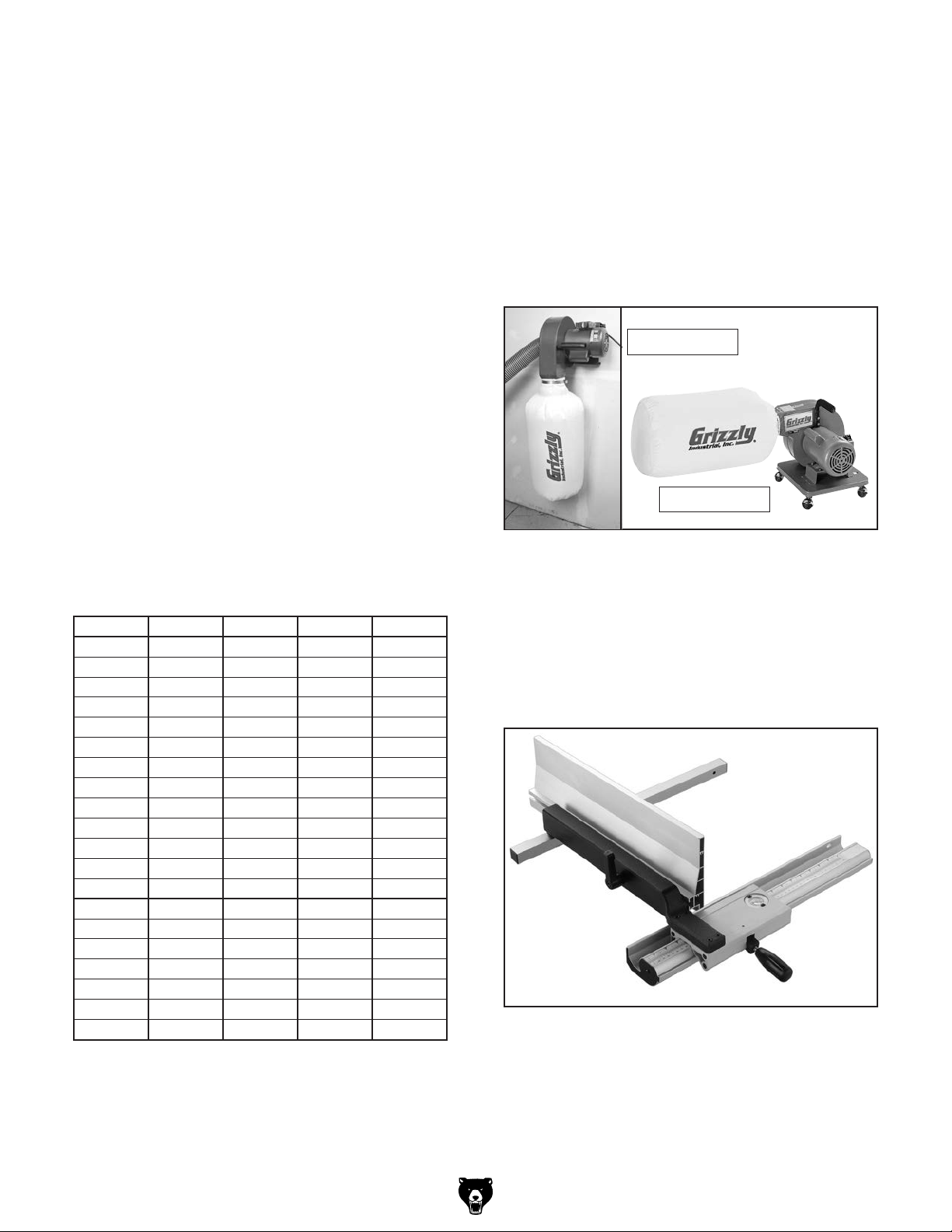
Timberwolf® 93 1⁄2" Bandsaw Blades
Timber Wolf® Band Mill Blades are high performance bands. The exclusive use of low tensioned,
high ductile Swedish silicon steel, unique geometric gullet designs and sets, unique manufacturing
processes and quality control has resulted in the
production of the finest band saw blades in the
world. High Performance (HP) and Raker (RK)
blades are specifically designed for detail work
in 1" and smaller kiln dried wood when a very
clean finish is required. They are also effective in
plywood and other woods where tear-out is a concern as well as the cutting of soft metals. Positive
Claw (PC) blades are everything a wood cutting
blade was meant to be. They have over 60%
of the speed capabilities of a hook style blade
with "hook" style gullet geometry and fast chip
removal, while giving you the great finish of a skip.
Alternate set (AS-S) blades are only .025" thick
with a total overall set is only .048 thousandths of
an inch. These bands were specifically designed
for straight-line resawing in very expensive, thick
woods. These blades utilize the thinnest kerf possible and provide a super finish when speed is
not a concern. You cannot go wrong with these
blades.
MODEL LENGTH WIDTH TPI GAUGE
H8507 93
H8508 93
H8509 931⁄2"
H8510 931⁄2"
H8511 931⁄2"
H8512 931⁄2"
H8514 931⁄2"
H8515 931⁄2"
H8516 931⁄2"
H8517 931⁄2"
H8518 931⁄2"
H8519 931⁄2"
H8520 93
H8521 931⁄2"
H8522 93
H8523 931⁄2"
H8524 931⁄2"
H8525 931⁄2"
H8526 931⁄2"
H8527 93
1
⁄2"
1
⁄2"
1
⁄2"
1
⁄2"
1
⁄2"
1
⁄8" 14 HP 0.025
3
⁄16" 10 RK 0.025
1
⁄4" 4 PC 0.025
1
⁄4" 6 PC 0.025
1
⁄4" 10 RK 0.025
1
⁄4" 12 RK 0.025
3
⁄8" 3 PC 0.025
3
⁄8" 4 PC 0.025
3
⁄8" 6 PC 0.025
3
⁄8" 10 RK 0.025
3
⁄8" 14 RK 0.025
1
⁄2" 3 PC 0.025
1
⁄2" 4 PC 0.025
1
⁄2" 6 PC 0.025
1
⁄2" 10 RK 0.025
1
⁄2" 14 RK 0.025
1
⁄2" 18 RK 0.025
3
⁄4" 3 AS-S 0.025
3
⁄4" 6 PC 0.032
3
⁄4" 10 RK 0.032
G1163—1HP Floor Model Dust Collector
G1163P—1HP Floor Model Dust Collector
G0710—1HP Wall-Mount Dust Collector
G0710P—1HP Wall-Mount Dust Collector
G3591—30 Micron Replacement Bag
H4340—3.0 Micron Upgrade Bag
Excellent point-of-use dust collectors that can
be used next to the machine with only a small
amount of ducting. Specifications: 450 CFM, 7.2"
static pressure, 2 cubic foot bag, and 30 micron
filter. Motor is 1HP, 110V/220V, 14A/7A.
Model G0710
Model G1163
Figure 58. Point-of-use dust collectors.
H7587—Re-Saw Fence Retrofit Kit
This retrofit kit allows you to upgrade your existing aluminum fence for the G0555LX bandsaw to
a cast-iron fence with the 6" high re-saw fence.
Simply unbolt your existing aluminum fence (4
bolts) and bolt on the new fence kit. Takes less
than 10 minutes to switch over.
Figure 59. H7587 Re-Saw Fence Retrofit Kit for
the G0555LX Bandsaw.
Order Online at grizzly.com
G0555LX (Mfg. Since 3/13)
®
-41-
Page 44
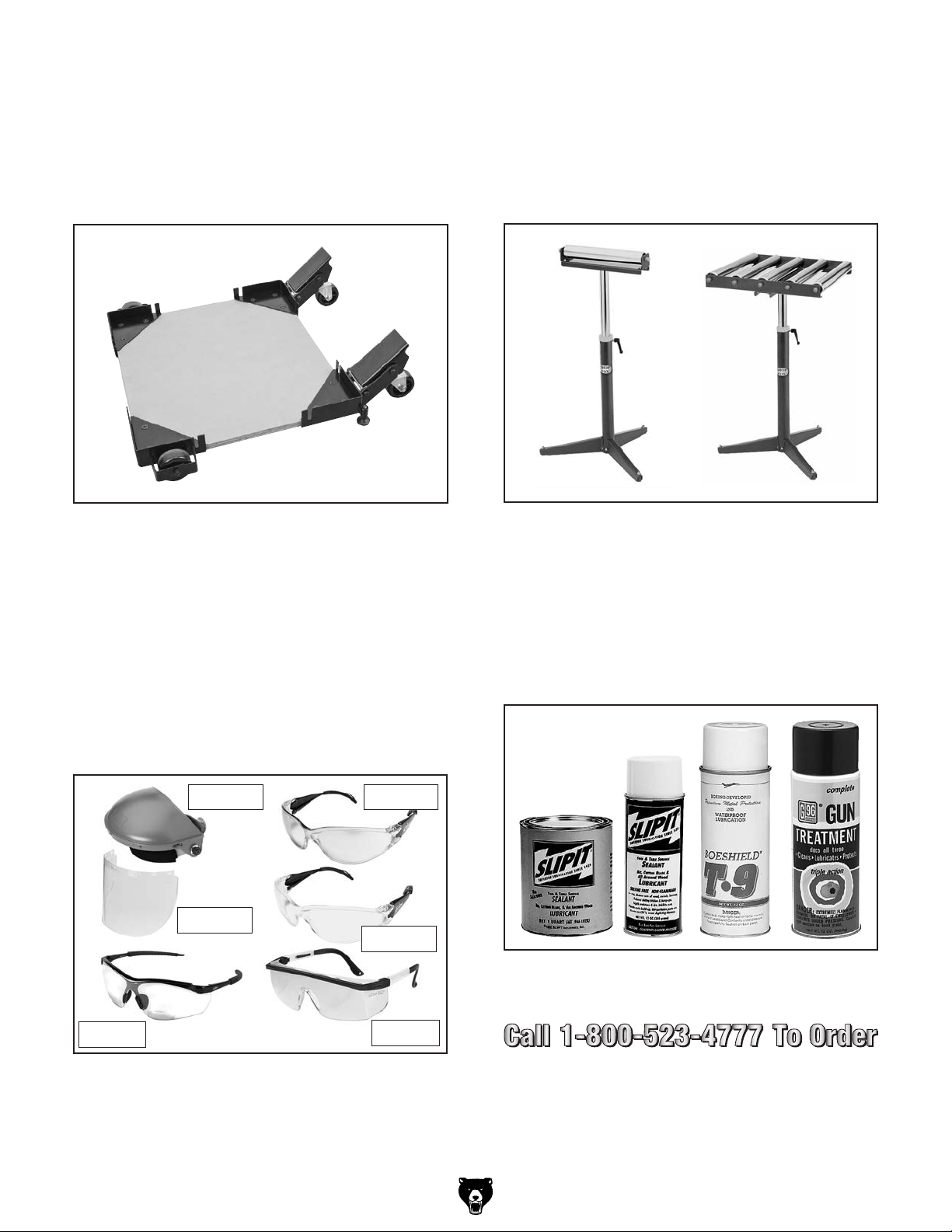
T23376—Universal Mobile Base
Just add your own piece of plywood to complete
this mobile kit for a custom fit under nearly any
size machine. Two kickstand-mounted swivel
casters easily drop down with a press from the
foot for a quick transition from a stationary base
to full maneuverability.
G8984—Single Roller Stand
G8985—5 Roller Stand
These roller stands are invaluable when working
solo in any shop for outfeeding and support tasks.
7
With 15
⁄8" wide rollers, adjustable 26"–44 5⁄8"
height, and all steel construction make them convenient and rugged.
Figure 60. T23376 SHOP FOX® Mobile Base.
Basic Eye Protection
T20501—Face Shield Crown Protector 4"
T20502—Face Shield Crown Protector 7"
T20503—Face Shield Window
T20452—"Kirova" Anti-Reflective S. Glasses
T20451—"Kirova" Clear Safety Glasses
H0736—Shop Fox
H7194—Bifocal Safety Glasses 1.5
H7195—Bifocal Safety Glasses 2.0
H7196—Bifocal Safety Glasses 2.5
®
Safety Glasses
T20502
T20503
T20452
T20451
Figure 62. G8984 and G8985 single and 5 roller
stands.
®
G5562—SLIPIT
G5563—SLIPIT
G2871—Boeshield
G2870—Boeshield
H3788—G96
H3789—G96
1 Qt. Gel
®
12 oz Spray
®
T-9 12 oz Spray
®
®
Gun Treatment 12 oz Spray
®
Gun Treatment 4.5 oz Spray
T-9 4 oz Spray
H7194
H0736
Figure 61. Assortment of basic eye protection.
Order Online at grizzly.com
-42-
Figure 63. Recommended lubricants for protect-
ing unpainted cast iron/steel part on machinery.
®
G0555LX (Mfg. Since 3/13)
Page 45

SECTION 6: MAINTENANCE
Always disconnect power
to the machine before
performing maintenance.
Failure to do this may
result in serious personal injury.
Schedule
For optimum performance from your machine, follow this maintenance schedule:
Lubricating
Protect the unpainted cast iron surfaces on the
table by wiping the table clean after every use—
this ensures moisture from wood dust does not
remain on bare metal surfaces. Keep tables
rust-free with regular applications of products like
®
Gun Treatment, SLIPIT®, Boeshield® T-9 on
G96
Page 40.
If the table becomes difficult to tilt, remove it and
lubricate the trunnions and the slides in the trunnion base.
Daily
• Check/correct loose mounting bolts.
• Check/correct damaged saw blade.
• Check/correct worn or damaged wires.
• Correct any other unsafe condition.
Monthly
• Check for V-belt tension, damage, or wear.
• Remove blade and thoroughly clean all builtup sawdust from the rubber tires on the
wheels.
• Clean/vacuum dust buildup from inside cabinet and off motor.
Cleaning
Vacuum excess wood chips and sawdust, and
wipe off the remaining dust with a dry cloth. If
resin has built up, use a resin dissolving cleaner
to remove it.
Redressing Rubber
Tires
As the bandsaw ages, the rubber tires on the
wheels may need to be redressed if they harden or
glaze over. Redressing the rubber tires improves
blade tracking and reduces vibration/blade lead.
If the rubber tires become too worn, then blade
tracking will become extremely difficult because
wheel crown will lose their proper shape. At that
point, redressing will no longer be effective and
the rubber tires must be replaced.
To redress the rubber tires:
1. DISCONNECT BANDSAW FROM POWER!
2. Put on heavy leather gloves.
3. Remove the blade.
Once a month, remove the blade and thoroughly
clean all built-up sawdust from the rubber tires on
the wheels.
G0555LX (Mfg. Since 3/13)
4. Clean any built-up sawdust from the rubber
tires.
5. Hold 100 grit sandpaper against the rub-
ber tire and rotate the wheel by hand. Only
redress the rubber enough to expose a fresh
rubber surface.
-43-
Page 46

Review the troubleshooting and procedures in this section if a problem develops with your machine. If you
need replacement parts or additional help with a procedure, call our Technical Support at (570) 546-9663.
Note: Please gather the serial number and manufacture date of your machine before calling.
SECTION 7: SERVICE
Troubleshooting
Symptom Possible Cause Possible Solution
Machine
does not
start or a
breaker trips.
Machine
stalls or is
underpowered.
Machine
has
vibration or
noisy operation.
1. Power supply is at fault/switched OFF.
2. Plug/receptacle is at fault or wired incorrectly.
3. Wiring is open/has high resistance.
4. Motor connection wired incorrectly.
5. Start capacitor is at fault.
6. Motor ON/OFF switch is at fault.
7. Centrifugal switch is at fault.
1. Incorrect workpiece material.
2. Feed rate too fast for task.
3. V-belt slipping.
4. Motor connection is wired incorrectly.
5. Plug/receptacle is at fault.
6. Motor bearings are at fault.
7. Motor has overheated.
8. Motor is at fault.
9. Centrifugal switch is at fault.
1. Motor or component is loose.
2. V-belt worn or loose.
3. Motor fan is rubbing on fan cover.
4. Pulley is loose.
5. Machine is incorrectly mounted or sits
unevenly on floor.
6. Blade is at fault.
7. Cast iron motor mount loose/broken.
8. Centrifugal switch is at fault.
9. Motor or spindle bearings are at fault.
1. Ensure hot lines have correct voltage on all
legs and main power supply is switched ON.
2. Test for good contacts; correct the wiring.
3. Check for broken wires or disconnected/
corroded connections, and repair/replace as
necessary.
4. Correct motor wiring connections (Page 53).
5. Test/replace.
6. Replace faulty ON/OFF switch.
7. Adjust/replace centrifugal switch.
1. Use wood with correct moisture content (20%
or less), without glues, and little pitch/resin.
2. Decrease feed rate.
3. Tighten/repair/replace (Pages 46 and 47).
4. Correct motor wiring connections (Page 53).
5. Test for good contacts; correct the wiring.
6. Test by rotating shaft; rotational grinding/loose
shaft requires bearing replacement.
7. Clean off motor, let cool, and reduce workload.
8. Test/repair/replace.
9. Adjust/replace centrifugal switch.
1. Inspect/replace stripped or damaged bolts/
nuts, use thread locking fluid, and retighten.
2. Tension V-belt (Page 46) or replace V-belt
(Page 47).
3. Replace dented fan cover; replace damaged fan.
4. Tighten pulley set screw.
5. Adjust stand feet.
6. Replace blade.
7. Tighten/replace.
8. Adjust/replace centrifugal switch..
9. Test by rotating shaft; rotational grinding/loose
shaft requires bearing replacement.
-44-
G0555LX (Mfg. Since 3/13)
Page 47

Symptom Possible Cause Possible Solution
Machine
slows when
operating.
1. Feeding workpiece too fast.
2. Blade is dull.
3. Workpiece moisture content is too high.
4. Incorrect workpiece type.
1. Reduce feed rate.
2. Replace blade (Page 36).
3. Replace workpiece.
4. Replace workpiece.
Ticking
sound when
the saw is
running.
Blade
contacting
table insert.
Vibration
when cutting.
Burn marks
on the edge
of the cut.
Rough or
poor quality
cuts.
Sawdust
buildup
inside
wheel covers.
Blade
wanders or
doesn't cut
straight.
Cuts are
not square
(vertically).
Tensioner
mechanism
has poor
range of motion.
Blade
tension
scale is
grossly
inaccurate.
Wheel is noisy. 1. Wheel bearing is worn out.
Blade does
not track.
1. Blade weld contacting guide/support
bearings (a light tick is normal).
2. Blade weld may be failing.
1. Table insert installed upside down or
backwards.
2. Table improperly mounted or aligned.
1. Loose or damaged blade.
2. Sawdust buildup on wheels.
1. Too much side pressure when feeding
workpiece; blade is binding.
2. Blade too wide for size of radius being cut.
1. Feeding workpiece too fast.
2. Blade guides adjusted incorrectly.
3. Incorrect blade selection.
1. Clogged dust port.
2. Low CFM (airflow) from dust collection
system.
1. Blade lead.
2. Sawdust buildup on wheels.
1. Table tilt is not adjusted to 0˚ or positive
stop has moved out of adjustment.
2. Table tilt scale pointer is not calibrated.
3. Table is not square to the blade.
1. Spacer blocks on quick-release tension
mechanism have moved out of adjustment.
1. The spring in the blade tension
mechanism has lost its "spring." This
is caused by not releasing the blade
tension when not in use or frequently
over-tensioning the bandsaw.
2. V-belt is too tight (lower wheel).
1. Wheels are not coplanar or aligned with
each other.
2. Rubber tires on wheels are worn out.
1. Use file or stone to smooth and round the back
of the blade; slightly loosen the blade guides.
2. Inspect and replace blade if necessary (Page 36).
1. Re-install table insert a different way.
2. Align table (Page 28).
1. Tighten or replace blade (Page 36).
2. Clean all sawdust from rubber tires on wheels.
1. Feed workpiece straight into the blade.
2. Install a smaller width blade/increase blade
tension (Page 34).
1. Reduce feed rate.
2. Re-adjust all blade support and guide bearings
(Pages 25 and 26).
3. Choose a the correct blade type for the operation.
1. Clean out dust port.
2. Four options:
—Check dust lines for leaks or clogs.
—Move dust collector closer to saw.
—Install a more powerful dust collector.
—Use blast gates to isolate the ducting between
—the bandsaw and dust collector.
1. Refer to Blade Lead on Page 50.
2. Clean all sawdust from rubber tires on wheels.
1. Adjust table tilt to 0˚; readjust positive stop if
necessary (Page 27).
2. Calibrate table tilt scale pointer to 0˚ (Page 27).
3. Shim table (Page 47).
1. Reset the blade tensioner (Page 52).
1. Replace spring in the blade tension mechanism,
then take better care of the bandsaw by
releasing tension when not in use and not overtensioning the blade.
1. Replace the wheel bearing.
2. Check/loosen the belt tension (Page 46).
1. Adjust wheels to be coplanar/aligned with each
other (Page 48).
2. Redress the rubber tires on the wheels (Page
43); replace the rubber tires on the wheels.
G0555LX (Mfg. Since 3/13)
-45-
Page 48

V-Belt Tension
To ensure optimum power transmission from the
motor to the blade, the V-belt must be in good
condition and operate under proper tension.
V-belt tension should be checked at least every
month—more often if the bandsaw is used daily. If
the belt shows signs of cracks, fraying, and excessive wear, replace it as instructed in Replacing
V-Belt on Page 47.
Checking V-Belt Tension
1. DISCONNECT BANDSAW FROM POWER!
2. Open the lower wheel cover.
Tensioning V-Belt
Tool Needed Qty
Hex Wrench 6mm .............................................. 1
To properly tension the V-belt:
1. DISCONNECT BANDSAW FROM POWER!
2. Open the lower wheel cover, and loosen
the motor adjustment and hinge cap screws
shown in Figure 65.
3. Check V-Belt deflection. The V-belt is prop-
erly tensioned if there is approximately
deflection. Deflection is checked by pushing the V-belt with moderate pressure, as
shown in Figure 64, and noting how much it
moves.
— If the V-belt is not properly tensioned,
perform the following Tensioning V-Belt
procedure.
Pulley
Approximately
Deflection
Pulley
1
⁄4"
1
⁄4"
Motor Mount
Cap Screws
Figure 65. Locations of the motor adjustment
and hinge cap screws.
3. Push the motor to the left (as viewed from the
front of the machine) until there is approximately
4. Re-tighten both cap screws and close the
wheel cover.
1
⁄4" deflection in the V-belt.
Figure 64. Checking the V-belt tension.
-46-
G0555LX (Mfg. Since 3/13)
Page 49

Replacing V-Belt
7. Remove the wheel from the shaft. Make sure
not to misplace the shaft key.
8. Put new belt on.
To ensure optimum power transmission from the
motor to the blade, the V-belt must be in good
condition and be properly tensioned.
Replace the V-belt if it shows signs of cracking,
fraying, and excessive wear.
Tools Needed Qty
Hex Wrench 6mm .............................................. 1
Wrench or Socket 13mm ................................... 1
Replacement V-Belt (Part No. P0555LX068) .... 1
To replace the V-belt:
1. DISCONNECT BANDSAW FROM POWER!
2. Put on heavy leather gloves and remove the
blade from the machine.
3. Loosen the motor mount cap screws shown
in Figure 66.
9. Align the wheel keyway with the shaft key,
and slide the wheel back onto the shaft.
10. Secure the wheel with the wheel mount bolt
and flat washer.
11. Position the V-belt on the desired pulleys,
then properly tension it, as instructed in
V-Belt Tension on Page 46.
12. Replace the blade, then properly track and
tension it (see Pages 19 and 23) and adjust
the guide and support bearings.
Shimming Table
To ensure accuracy when cutting stacked cuts or
circles, the table must be 90° to the back of the
blade, as shown in Figure 67.
Motor Mount
Cap Screws
Wheel Mount
Bolt
Figure 66. Locations of the wheel mount bolt,
and motor mount cap screws.
4. Pivot the motor to the right (as viewed from
the front of the bandsaw) so the upper cap
screw slides to the right in the slot—this will
release the V-belt tension.
5. Roll the V-belt off the pulleys.
6. Remove the wheel mount (it has left hand
threads, so it loosens by turning clockwise).
Figure 67. Checking the table to be
perpendicular to the back of the blade.
If the table is not perpendicular to the back of
the blade, correct this condition by placing shims
between the table and trunnions underneath it.
Follow the procedures in Aligning Table on Page
28 to ensure accurate cutting.
G0555LX (Mfg. Since 3/13)
-47-
Page 50

Wheel Alignment
Wheel alignment is important for optimal performance from your bandsaw. Wheels are properly
aligned when they are parallel with each other and
in the same plane or “coplanar” (see the illustration in the figure to the right).
When wheels are coplanar, the bandsaw is
more likely to cut straight without wandering; and
vibration, heat, and blade wear are considerably
decreased because the blade is automatically balanced on the wheel.
Bringing the wheel into alignment may require
a combination of shimming a wheel and center/
lateral tracking the blade.
Tools Needed Qty
Straightedge 4 ft. ............................................... 1
Fine Ruler .......................................................... 1
Wrench or Socket 13mm ................................... 1
Wrench or Socket 19mm ................................... 1
Checking Wheel Alignment
1. DISCONNECT BANDSAW FROM POWER!
2. Remove the table.
3. With the blade on and properly tensioned,
hold a straightedge close to the center of
both wheels. Make sure the straightedge fully
extends across the rims of both wheels, as
shown in Figure 68.
Top and bottom
wheels parallel and
aligned: No adjust-
ment needed.
or
Wheels parallel, but
top or bottom wheel
is not parallel with
the other wheel:
Move the top wheel
in or out.
4. Referring to Figure 69, check wheel alignment.
Figure 68. Checking if the wheels are coplanar.
-48-
Top wheel is not verti-
cally aligned with the
bottom wheel: Use the
blade tracking knob to
tilt the top wheel.
Figure 69. Wheel alignment illustration.
Top wheel is not later-
ally aligned with the
bottom wheel: Adjust
the rear adjustment set
screws to tilt the top
wheel left/right.
G0555LX (Mfg. Since 3/13)
Page 51

Shimming a Wheel
A wheel that is parallel with the other wheel, but
is not coplanar, must be shimmed by the distance
that it is not in the same plane with the other
wheel.
8. Perform the previous Checking Wheel
Alignment procedure. If necessary to make
the wheels parallel, repeat this procedure.
9. Close the wheel covers.
Tip: Electrical washers work well for shimming
the wheel because the can easily be stacked
to get the desired height.
To shim a wheel:
1. DISCONNECT BANDSAW FROM POWER!
2. Adjust the upper wheel tracking so that it is
parallel with the bottom wheel.
3. With the straightedge touching both rims of
the wheel that does not need to be adjusted,
measure the distance away from the other
wheel with a fine ruler, as shown in Figure 70.
The distance measured with the ruler is the
distance this wheel must be shimmed.
10. The first time you get the wheels coplanar,
place a mark on each wheel where you held
the straightedge, then use this position again
in the future if you need to repeat the procedure. This assures repeated accuracy every
time you adjust the wheels.
Upper Wheel Lateral Adjustment
If the upper wheel is tilted laterally (side to side),
perform the following procedure to make it coplanar with the lower wheel.
There are two set screws in the upper wheel
bracket, shown in Figure 71, that adjust the wheel
tilt from side to side.
Figure 70. Measuring the distance to shim the
wheel to be coplanar.
4. Remove the blade.
5. Remove the wheel to be shimmed. Place as
many shims as necessary to correct the gap
measured in Step 3 onto the wheel shaft.
6. Re-install the wheel and secure it in place.
7. Re-install the blade and properly tension it.
Rear Adjustment
Set Screw
Figure 71. Rear lateral adjustment set screw.
Tools Needed Qty
Hex Wrench 3mm .............................................. 1
Wrench or Socket 10mm ................................... 1
To adjust the upper wheel laterally:
1. DISCONNECT BANDSAW FROM POWER!
2. Remove the fence and table from the
machine.
G0555LX (Mfg. Since 3/13)
-49-
Page 52

3. Using a white crayon or other light color
marker, mark the upper and lower wheels
to indicate the measuring locations, as illustrated in Figure 72.
Upper Wheel
A1
B1
Blade Lead
Bandsaw blades may wander off the cut line when
sawing, as shown in Figure 74. This is called
blade lead.
Blade lead is usually caused by too fast of a
feed rate, a dull or abused blade, or improper
blade tension. If your blade is sharp/undamaged,
properly tensioned, and you still have blade lead,
perform the following procedures.
A2
Figure 72. Example of marking upper and lower
wheels for consistent measurements.
Note: Marking the wheels ensures more accurate
results in case there are irregularities in the
wheels.
4. Using a straightedge, check the wheels at the
A and B locations (see Figure 72).
5. Using the 10mm wrench, loosen the hex nuts
on the rear adjustment set screws.
6. Using the 3mm hex wrench, adjust the set
screws until the upper wheel is coplanar with
the lower wheel, see Figure 73.
B2
Lower Wheel
Figure 74. Example of blade lead.
To correct blade lead:
1. Make sure the blade is properly tensioned
and the blade guides are adjusted correctly.
2. Use less pressure when feeding the workpiece
through the cut.
Viewed From Above
Before lateral
adjustment
Straightedge
Figure 73. Before and after lateral wheel
alignment (viewed from above).
7. Re-tighten the hex nuts loosened in Step 6.
-50-
After lateral
adjustment
3. Make sure the miter slot and fence are parallel to the blade line (see the Aligning Table
and Aligning Fence procedures in this manual for detailed information).
4. Perform a test cut with the bandsaw.
— If there is still blade lead present, compen-
sate for this condition by skewing the fence
or shifting the table, as instructed in the
following procedures.
G0555LX (Mfg. Since 3/13)
Page 53
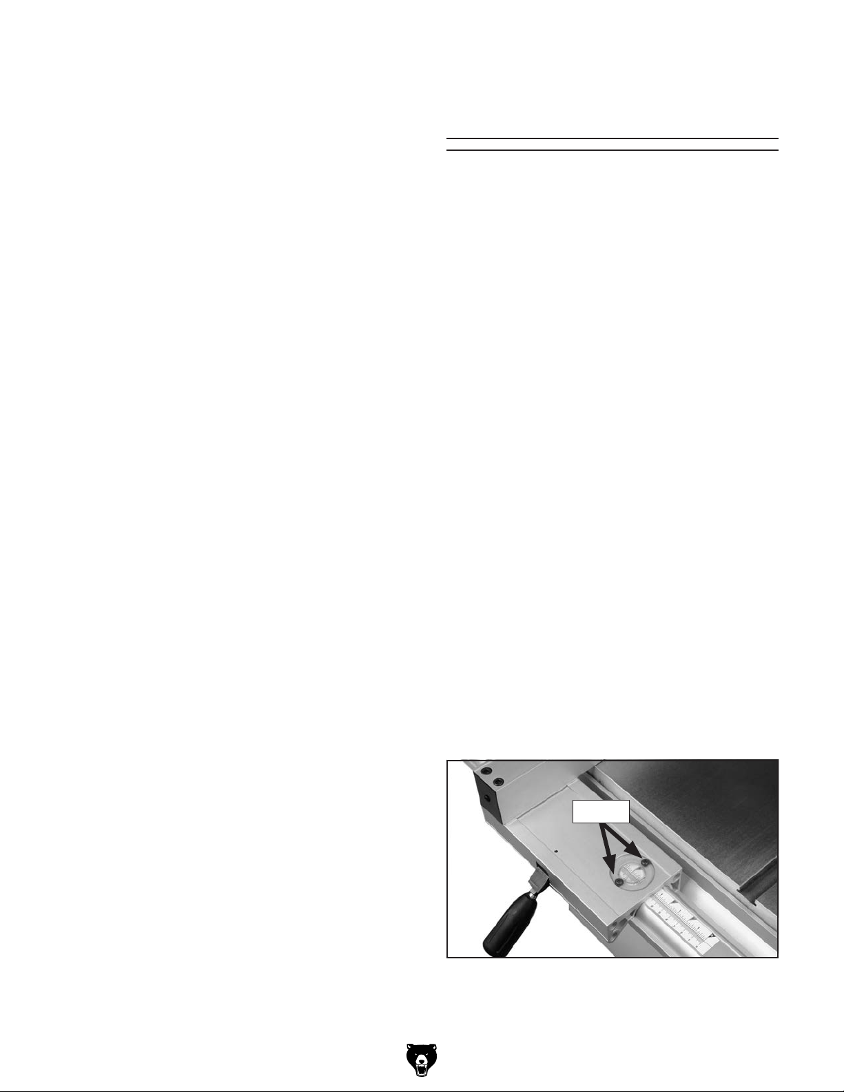
To skew your fence:
3
1. Cut a piece of scrap wood approximately
thick x 3" wide x 17" long. On the wide face of
the board, draw a straight line parallel to the
long edge.
2. Slide the bandsaw fence out of the way and
cut along the line halfway through the board.
Turn the bandsaw OFF and wait for the blade
to stop. Do not move the board.
⁄4"
Fence Scale
Calibration
You may need to recalibrate the fence scale after
changing or adjusting the blade, or if the scale
is not producing accurate cuts. Recalibrate the
fence scale by adjusting the hairline indicator on
the fence and testing your adjustment by cutting a
piece of scrap wood.
3. Clamp the board to the bandsaw table, then
slide the fence over to the board so it barely
touches one end of the board.
4. Use a 4mm hex wrench to loosen the four
fence adjustment cap screws on top of the
fence, skew the fence so that it is parallel
with the scrap piece, then re-tighten the cap
screws.
5. Make a few cuts using the fence.
— If blade lead is still present, repeat Steps
1–4 until the blade and fence are parallel
with each other.
— Or, shift the table, as instructed in the fol-
lowing procedure.
To shift the table:
1. On a scrap piece of wood, mark a line that is
perpendicular to the front edge.
2. Cut halfway through the board on the line by
pushing it into the blade.
Tools Needed Qty
Phillips Screwdriver #1 ...................................... 1
To calibrate the scale:
1. Set the fence anywhere along the scale and
locate a piece of scrap wood with at least one
straight edge.
Note: Joint the edge with a jointer if needed
to make the edge straight.
2. Hold the straight edge of the workpiece firmly
against the fence, and feed the workpiece
through the saw blade with a push stick.
3. Measure the width of the cut workpiece. The
width of the workpiece should match the
reading on the fence scale.
4. If the reading on the scale is not the same
as the width of the cut workpiece, loosen the
two screws on the magnifying window (see
Figure 75) and adjust it to match the width of
the cut workpiece.
3. Turn the bandsaw OFF and wait for the blade
to stop.
4. Disconnect the bandsaw from power, then
use a 10mm wrench to loosen the six hex
bolts underneath the table that secure it to
the trunnion brackets.
5. Shift the table to compensate for the blade
lead, re-tighten the hex bolts, then re-connect
the bandsaw to power.
6. Repeat Steps 1–5 until there is no longer any
blade lead.
G0555LX (Mfg. Since 3/13)
Screws
Figure 75. Fence scale window and screws.
5. Re-tighten the screws—the scale is now cor-
rectly calibrated.
-51-
Page 54
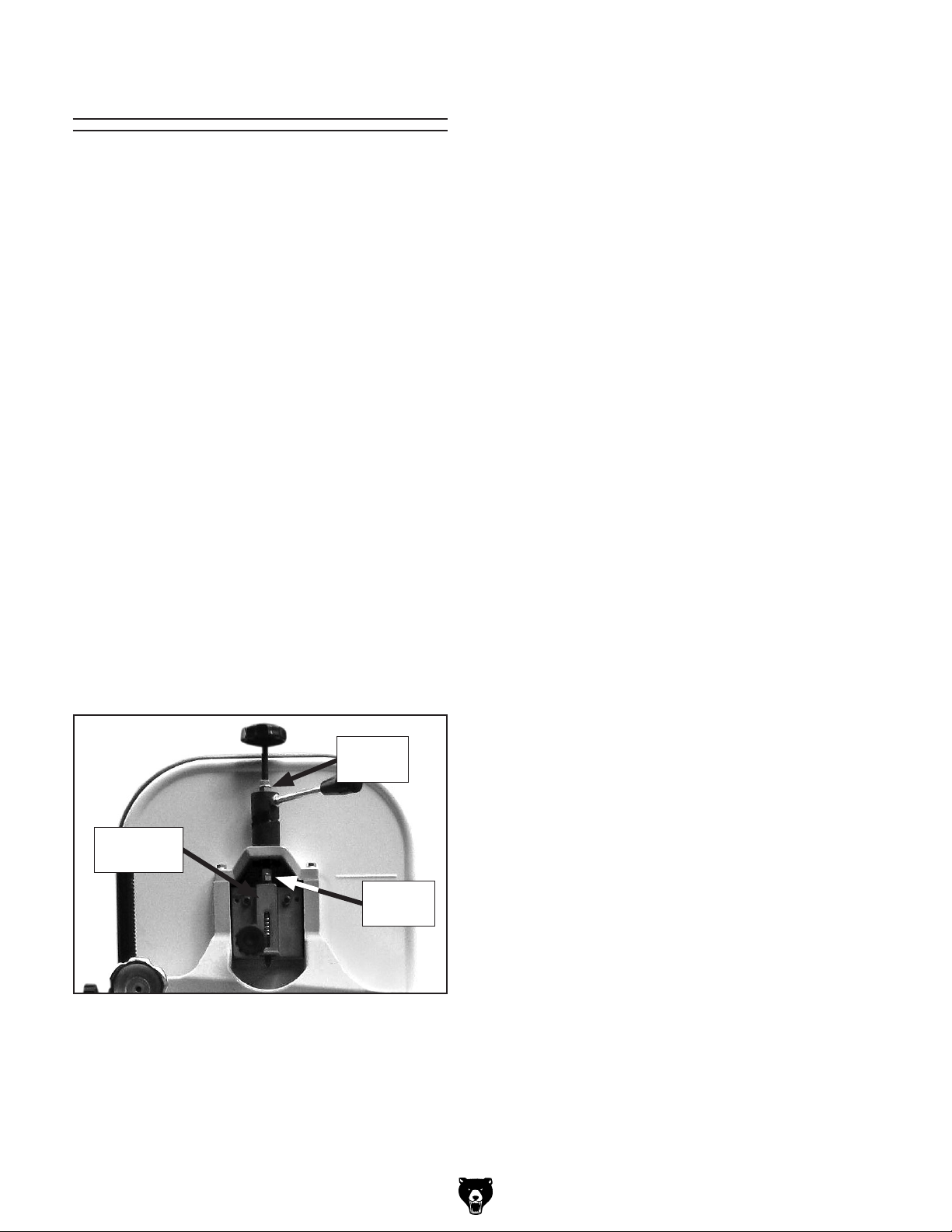
Blade Tensioner
3. Using two 14mm wrenches, loosen the lower
jam nuts and thread them up the shaft.
The blade tensioner may need to be reset for one
of the following reasons:
• The blade tension quick release lever will not
move to the right position when the tension
scale is correctly adjusted for the installed
blade.
• You have installed a blade of a different
length and the tensioner needs tightened.
The procedure below describes how to decompress
the spring in the blade tensioner to allow the quick
release lever to perform its intended purpose. If
the tensioner needs tightened, reverse the procedure to get the desired results.
Tool Needed Qty
Wrench 14mm ................................................... 2
To reset the blade tensioner:
4. Using the two 14mm wrenches, loosen the
upper jam nuts and thread them up the shaft
the same distance as the lower jam nuts.
5. Test the blade tensioner setting by moving
the quick release lever to the right.
6. Use the blade tensioner knob to final tension
the blade.
7. Repeat the procedure until the proper ten-
sion and release are achieve with the quick
release lever.
Note: Over compressing the spring will wear it
out prematurely, making the blade tensioner
sloppy and inaccurate. Only compress the
spring as needed to remove play in the system.
1. DISCONNECT BANDSAW FROM POWER!
2. Move the blade tension quick release lever
to the left position to release blade tension.
Figure 76.
Upper
Jam Nut
Tensioner
Casting
Lower
Jam Nut
Figure 76. Locations of spacers and tensioner
crossbar.
-52-
G0555LX (Mfg. Since 3/13)
Page 55

These pages are current at the time of printing. However, in the spirit of improvement, we may make changes to the electrical systems of future machines. Compare the manufacture date of your machine to the one
number and manufacture date of your
machine before calling. This information can be found on the main machine label.
machine
SECTION 8: WIRING
stated in this manual, and study this section carefully.
If there are differences between your machine and what is shown in this section, call Technical Support at
(570) 546-9663 for assistance BEFORE making any changes to the wiring on your machine. An updated
wiring diagram may be available. Note : Please gather the serial
Wiring Safety Instructions
SHOCK HAZARD. Working on wiring that is connected to a power source is extremely dangerous.
Touching electrified parts will result in personal
injury including but not limited to severe burns,
electrocution, or death. Disconnect the power
from the machine before servicing electrical components!
MODIFICATIONS. Modifying the wiring beyond
what is shown in the diagram may lead to unpredictable results, including serious injury or fire.
This includes the installation of unapproved aftermarket parts.
WIRE CONNECTIONS. All connections must
be tight to prevent wires from loosening during
machine operation. Double-check all wires disconnected or connected during any wiring task to
ensure tight connections.
CIRCUIT REQUIREMENTS. You MUST follow
the requirements at the beginning of this manual when connecting your machine to a power
source.
WIRE/COMPONENT DAMAGE. Damaged wires
or components increase the risk of serious personal injury, fire, or machine damage. If you notice
that any wires or components are damaged while
performing a wiring task, replace those wires or
components.
MOTOR WIRING. The motor wiring shown in
these diagrams is current at the time of printing
but may not match your machine. If you find this
to be the case, use the wiring diagram inside the
motor junction box.
CAPACITORS/INVERTERS. Some capacitors
and power inverters store an electrical charge for
up to 10 minutes after being disconnected from
the power source. To reduce the risk of being
shocked, wait at least this long before working on
capacitors.
EXPERIENCING DIFFICULTIES. If you are experiencing difficulties understanding the information
included in this section, contact our Technical
Support at (570) 546-9663.
The photos and diagrams
included in this section are
best viewed in color. You
can view these pages in
color at www.grizzly.com.
G0555LX (Mfg. Since 3/13)
-53-
Page 56

Electrical Locations
Figure 77. G0555LX ON/OFF switch.
Switch
Motor
-54-
READ ELECTRICAL SAFETY
ON PAGE 53!
G0555LX (Mfg. Since 3/13)
Page 57

110V (Prewired) Wiring Diagram
(Switches Viewed from Behind)
Start/Stop Switch
ON
OFF
Ground
Neutral
Hot
Ground
Start Capacitor
300MFD 125VAC
110 VAC
5-15 Plug
(Pre-wired)
Motor
110V
Ground
G0555LX (Mfg. Since 3/13)
-55-
Page 58
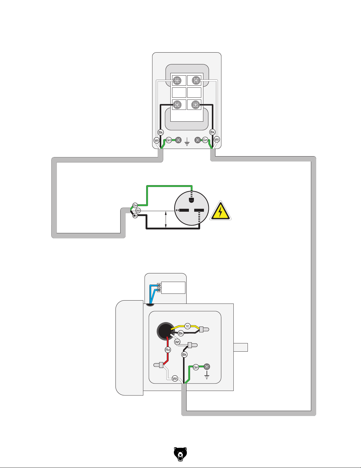
220V (Rewired) Wiring Diagram
(Switches Viewed from Behind)
Start/Stop Switch
ON
OFF
Ground
Ground
G
Hot
Motor
220V
220
VAC
Hot
6-15 Plug
(As Recommended)
Start Capacitor
300MFD 125VAC
220 VAC
Ground
-56-
G0555LX (Mfg. Since 3/13)
Page 59

SECTION 9: PARTS
Main
50
49
60
49
76
41
50
66
65
44
46
51
42
47
63
43
55
58
51
64
59
56
48
61
55
41
62
57
56
16
154
43
57
167
173
40
22
45
44
8
3
4
70
69
14
14-2
14-1
16
15
7
17
186
68
64
115
155
195
34
194
14-3
6
30
24
116
168
35
21
23
76
125
19
124
117
75
141
96
127
5
1
212
39
128
131
169
38
2
28
129
95
31
7
3
128
71
72
72
73
74
193
119
118
9
139
10
154
83
94
138
140
167
155
82
96
93
88
13
135
81
129
190
80
8
120
113
80
29
11
12
170
79
89
162
85
25
11-2
33
131
121
11-3
11-8
141
131
214
84
86
11-6
134
133
122
123
90
191
92
26
11-4
11-5
11-1
11-7
11-9
G0555LX (Mfg. Since 3/13)
-57-
Page 60

Main Parts List
REF PART # DESCRIPTION REF PART # DESCRIPTION
1 P0555LX001 BASE 42 PLN16 LOCK NUT 1/2-20 THIN
2 PB64 HEX BOLT 5/8-11 X 2-1/2 43 PR21M INT RETAINING RING 35MM
3 PW14 FLAT WASHER 5/8 44 P6202-2RS BALL BEARING 6202-2RS
4 PN04 HEX NUT 5/8-11 45 P0555LX045 LOWER WHEEL
5 P0555LX005 GUIDE PIN 6 X 15MM 46 PW07 FLAT WASHER 5/16
6 P0555LX006 LOWER WHEEL SHAFT 47 PB104 HEX BOLT 5/16-18 X 3/4 LH
7 P6204-2RS BALL BEARING 6204-2RS 48 P0555LX048 LOWER WHEEL GUARD
8 PK23M KEY 5 X 5 X 25MM 49 P0555LX049 KNOB 5/16-18
9 PW07 FLAT WASHER 5/16 50 PTLW03M INT TOOTH WASHER 8MM
10 PB32 HEX BOLT 5/16-18 X 5/8 51 P0555LX051 STUD LATCH
11 P0555LX011 MOTOR 1HP 110V/220V 1PH 55 PS01 PHLP HD SCR 10-24 X 1/2
11-1 P0555LX011-1 MOTOR FAN 56 P0555LX056 CATCH
11-2 P0555LX011-2 FAN COVER 57 P0555LX057 LOCATING BOLT
11-3 P0555LX011-3 WIRING BOX 58 PHTEK7 TAP SCREW #8 X 3/8
11-4 P0555LX011-4 CAPACITOR COVER 59 P0555LX059 FRONT UPPER COVER
11-5 P0555LX011-5 S CAPACITOR 300M 125V 60 P0555LX060 SAW BLADE 93-1/2 X 3/8 X 6TPI HOOK
11-6 P0555LX011-6 CONTACTOR PLATE 61 P0555LX061 BACK UPPER COVER
11-7 P0555LX011-7 CENTRIFUGAL SWITCH 1725 RPM 62 PFS03 FLANGE SCREW 10-24 X 3/8
11-8 P6205-2RS BALL BEARING 6205-2RS 63 P0555LX063 UPPER HINGE
11-9 P6204-2RS BALL BEARING 6204-2RS 64 P0555LX064 STANDOFF STUD-MF
12 P0555LX012 MOTOR PULLEY 65 P0555LX065 SAW BLADE GUARD
13 PSS07 SET SCREW 1/4-20 X 1/2 66 P0555LX066 BLADE GUARD WASHER #10
14 P0555LX014 PUSH BUTTON SWITCH ASSY 68 P0555LX068 RIBBED V-BELT 200J5
14-1 P0555LX014-1 SWITCH COVER 69 P0555LX069 LOWER WHEEL COVER HINGE
14-2 P0555LX014-2 SWITCH CONTROL 70 PS06 PHLP HD SCR 10-24 X 3/8
14-3 P0555LX014-3 SWITCH BOX 71 PB11 HEX BOLT 5/16-18 X 1-1/2
15 P0555LX015 TAP SCREW #10 X 1 72 PW07 FLAT WASHER 5/16
16 PW03 FLAT WASHER #10 73 PLW01 LOCK WASHER 5/16
17 PS22 PHLP HD SCR 10-24 X 5/8 74 PN02 HEX NUT 5/16-18
19 PTLW08M EXT TOOTH WASHER 10MM 75 P0555LX075 CORD CLAMP
21 P0555LX021 SWITCH PLATE 76 PS01 PHLP HD SCR 10-24 X 1/2
22 P0555LX022 WHEEL PULLEY 79 P0555LX079 UPPER BLADE GUIDE CASTING
23 PS18 PHLP HD SCR 10-24 X 1/4 80 PCAP04 CAP SCREW 1/4-20 x 1/2
24 P0555LX024 STRAIN RELIEF 81 P0555LX081 BEARING ARBOR
25 P0555LX025 POWER CORD 16G 3W 5-15 120" 82 P6000-2RS BALL BEARING 6000-2RS
26 P0555LX026 MOTOR CORD 16G 3W 83 PFH09 FLAT HD SCR 1/4-20 X 5/16
28 P0555LX028 UPPER FRAME ARM 84 P0555LX084 GUIDE POST
29 P0555LX029 KNOB BOLT 5/16-18 X 3/4 85 PLW03 LOCK WASHER 3/16
30 P0555LX030 SLIDING HOUSING 86 PCAP110 CAP SCREW 10-24 X 1-3/4
31 PWN03 WING NUT 5/16-18 88 P0555LX088 LOWER BLADE GUIDE BRACKET
33 P0555LX033 TENSION BOLT 3/8-16 X 11-5/8 89 P0555LX089 GUIDE SHAFT BRACKET
34 P0555LX034 PIVOT PIN 90 P0555LX090 UPPER BLADE GUARD
35 P0555LX035 UPPER WHEEL SHAFT 92 PS06 PHLP HD SCR 10-24 X 3/8
38 P0555LX038 COMPRESSION SPRING 93 P0555LX093 LOWER BRACKET POST
39 P0555LX039 INDICATOR NUT 3/8 X 16 94 PW06 FLAT WASHER 1/4
40 P0555LX040 UPPER WHEEL 95 PB05 HEX BOLT 1/4-20 X 3/4
41 P0555LX041 WHEEL TIRE 96 PCAP109 CAP SCREW 10-32 X 1/4
-58-
G0555LX (Mfg. Since 3/13)
Page 61

REF PART # DESCRIPTION REF PART # DESCRIPTION
Main Parts List (continued)
113 PN02 HEX NUT 5/16-18 139 PLW01 LOCK WASHER 5/16
115 PB03 HEX BOLT 5/16-18 X 1 140 P0555LX140 CLUTCH SUPPORT BRACKET
116 PLW01 LOCK WASHER 5/16 141 PLW04 LOCK WASHER 3/8
117 PW07 FLAT WASHER 5/16 154 PCAP06 CAP SCREW 1/4-20 X 1
118 P0555LX118 PINION SHAFT 155 PSS04 SET SCREW 1/4-20 X 5/16
119 P0555LX119 LOCK COLLAR 162 P0555LX162 BALL PLUNGER 1/4-20 X 1/2
120 P0555LX120 GUIDE POST CONTROL KNOB 167 PLW02 LOCK WASHER 1/4
121 PSS100 SET SCREW 5/16-24 X 1-1/2 168 PSS12 SET SCREW 1/4-20 X 1
122 P0555LX122 ADJUST NUT 169 PN05 HEX NUT 1/4-20
123 PCAP01 CAP SCREW 1/4-20 X 5/8 170 P0555LX170 DOG PT SET SCR 5/16-18 X 1/2
124 P0555LX124 CORD CLAMP 3/8 173 P0555LX173 BUSHING
125 PS01 PHLP HD SCR 10-24 X 1/2 186 P0555LX186 SWITCH PADLOCK
127 PW04M FLAT WASHER 10MM 190 PCAP17 CAP SCREW 1/4-20 X 3/8
128 P608-2RS BALL BEARING 608-2RS 191 PW02M FLAT WASHER 5MM
129 P0555LX129 ECCENTRIC 193 P0555LX193 KNOB BOLT 5/16-18 X 2
131 PN08 HEX NUT 3/8-16 194 P0555LX194 SHAFT BRACKET
133 P0555LX133 STUD-UDE 195 PRP73M ROLL PIN 4 X 30
134 P0555LX134 PLASTIC HANDLE 3/8-16 212 PW02 FLAT WASHER 3/8
135 P0555LX135 UPPER CLUTCH 214 P0555LX214 LOWER CLUTCH
138 PB12 HEX BOLT 5/16-18 X 1-1/4
G0555LX (Mfg. Since 3/13)
-59-
Page 62

58
53
Table, Fence, & Stand
161
198
98
99
97
52
160
166
95
94
37
106
104
73
103
101
102
111
109
53
108
58
113
112
110
132
199
104
105
204
87
70
113
100
197
131
205
36
192
153
206
207
27
78
157
130
32
54
107
77
126
163
161
87
130
172
200
127
158
159
55
184
-60-
202
114-2
114-10
114-1
114-7
114-5
114-9
114-12
201
114-8
114-14
114-13
114-6
114-3
114-4
114
212
211
213
208
211
212
209
210
G0555LX (Mfg. Since 3/13)
Page 63

Table, Fence & Guides Parts List
REF PART # DESCRIPTION REF PART # DESCRIPTION
27 PCAP43 CAP SCREW 1/4-20 X 2-1/2 114-7 P0555LX114-7 STUD-SE 1/4-20 X 1-1/8
32 PS28M PHLP HD SCR M8-1.25 X 30 114-8 P0555LX114-8 PLASTIC FLAT WASHER 1/4
36 P0555LX036 LOCK CAM 114-9 PW06 FLAT WASHER 1/4
37 P0555LX037 LARGE FENCE RAIL 114-10 P0555LX114-10 STUD-SE 1/4-20 X 3/4
52 P0555LX052 SMALL FENCE RAIL 114-12 PFH08 FLAT HD SCR 10-24 X 1/2
53 P0555LX053 LARGE RAIL CAP 114-13 PW02M FLAT WASHER 5MM
54 P0555LX054 MAGNIFIED LENS 114-14 PS01 PHLP HD SCR 10-24 X 1/2
55 PS01 PHLP HD SCR 10-24 X 1/2 126 PSS02 SET SCREW 5/16-18 X 3/8
58 PHTEK7 TAP SCREW #8 X 3/8 127 PW04M FLAT WASHER 10MM
70 PS06 PHLP HD SCR 10-24 X 3/8 130 P0555LX130 BEARING PAD
73 PLW01 LOCK WASHER 5/16 131 PN08 HEX NUT 3/8-16
77 P0555LX077 FENCE 132 P0555LX132 HANDLE BOLT 5/16-18
78 P0555LX078 SPACER 153 P0555LX153 CAM WEAR PLATE
87 P0555LX087 FENCE CAP 157 PB58 HEX BOLT 3/8-16 X 2
94 PW06 FLAT WASHER 1/4 158 PN01M HEX NUT M6-1
95 PB05 HEX BOLT 1/4-20 X 3/4 159 P0555LX159 RUB FOOT M6-1.0
97 P0555LX097 TABLE 160 PCAP01 CAP SCREW 1/4-20 X 5/8
98 P0555LX098 LARGE TABLE INSERT 161 P0555LX161 REAR RAIL END CAP
99 PRP15M ROLL PIN 3 X 8 163 PFH19 FLAT HD SCR 1/4-20 X 3/8
100 P0555LX100 TABLE LOCK PIN 166 P0555LX166 FENCE SCALE
101 P0555LX101 TRUNNION 169 PN05 HEX NUT 1/4-20
102 P0555LX102 TILT SCALE 172 P0555LX172 L BRACE
103 P0555LX103 TRUNNION CLAMP SHOE 184 P0555LX184 SMALL FENCE PAD
104 PB19 HEX BOLT 1/4-20 X 1/2 192 PFS03 FLANGE SCREW 10-24 X 3/8
105 P0555LX105 TRUNNION BASE 197 P0555LX197 PLATE
106 PB12 HEX BOLT 5/16-18 X 1-1/4 198 P0555LX198 SMALL TABLE INSERT
107 P0555LX107 FENCE CARRIAGE, ALUMINUM 199 PW06 FLAT WASHER 1/4
108 P0555LX108 POINTER 200 P0555LX200 ADJUST PLATE
109 PS18 PHLP HD SCR 10-24 X 1/4 201 P0555LX201 STAND TOP
110 P0555LX110 FEMALE KNOB 3/8-16 202 PCB01 CARRIAGE BOLT 5/16-18 X 5/8
111 PB58 HEX BOLT 3/8-16 X 2 204 PFN02 FLANGE NUT 5/16-18
112 PB22 HEX BOLT 5/16-18 X 1-3/4 205 P0555LX205 STAND SIDE
113 PN02 HEX NUT 5/16-18 206 PB02 HEX BOLT 1/4-20 X 5/8
114 P0555LX114 MITER GAUGE ASSY 207 PW06 FLAT WASHER 1/4
114-1 P0555LX114-1 MITER GAUGE BODY 208 PFN01 FLANGE NUT 1/4-20
114-2 P0555LX114-2 MITER BAR 209 P0555LX209 UPPER STAND BRACE
114-3 P0555LX114-3 STOP BLOCK 210 P0555LX210 LOWER STAND BRACE
114-4 P0555LX114-4 STOP DOWEL 211 PN08 HEX NUT 3/8-16
114-5 P0555LX114-5 FEMALE HANDLE 1/4-20 212 PW02 FLAT WASHER 3/8
114-6 P0555LX114-6 SCALE PLATE 213 P0555LX213 STAND FOOT 3/8-16 X 2
G0555LX (Mfg. Since 3/13)
-61-
Page 64

215
Labels
216
225
224
223
220
217
217
222
216
221
218
219
REF PART # DESCRIPTION REF PART # DESCRIPTION
215 P0555LX215 MACHINE ID LABEL CSA 221 PPAINT-11 TOUCH UP PAINT-PUTTY
216 PLABEL-23 BLADE DOOR LABEL 222 PLABEL-62A DISCONNECT POWER LABEL
217 PLABEL-19B BANDSAW BLADE LABEL 223 PLABEL-14A ELECTRICITY LABEL
218 PPAINT-1 TOUCH UP PAINT-GRIZZLY GREEN 224 PLABEL-11A SAFETY GLASSES LABEL
219 P0555LX219 MODEL NUMBER LABEL 225 PLABEL-12A READ MANUAL LABEL
220 P0555LX220 GRIZZLY.COM LABEL
Safety labels help reduce the risk of serious injury caused by machine hazards. If any label comes
off or becomes unreadable, the owner of this machine MUST replace it in the original location
before resuming operations. For replacements, contact (800) 523-4777 or www.grizzly.com.
-62-
G0555LX (Mfg. Since 3/13)
Page 65

WARRANTY CARD
Name _____________________________________________________________________________
Street _____________________________________________________________________________
City _______________________ State _________________________ Zip _____________________
Phone # ____________________ Email _________________________________________________
Model # ____________________ Order # _______________________ Serial # __________________
The following information is given on a voluntary basis. It will be used for marketing purposes to help us develop
better products and services. Of course, all information is strictly confidential.
1. How did you learn about us?
____ Advertisement ____ Friend ____ Catalog
____ Card Deck ____ Website ____ Other:
2. Which of the following magazines do you subscribe to?
____ Cabinetmaker & FDM
____ Family Handyman
____ Hand Loader
____ Handy
____ Home Shop Machinist
____ Journal of Light Cont.
____ Live Steam
____ Model Airplane News
____ Old House Journal
____ Popular Mechanics
3. What is your annual household income?
____ $20,000-$29,000 ____ $30,000-$39,000 ____ $40,000-$49,000
____ $50,000-$59,000 ____ $60,000-$69,000 ____ $70,000+
CUT ALONG DOTTED LINE
4. What is your age group?
____ 20-29 ____ 30-39 ____ 40-49
____ 50-59 ____ 60-69 ____ 70+
5. How long have you been a woodworker/metalworker?
____ 0-2 Years ____ 2-8 Years ____ 8-20 Years ____20+ Years
6. How many of your machines or tools are Grizzly?
____ 0-2 ____ 3-5 ____ 6-9 ____10+
____ Popular Science
____ Popular Woodworking
____ Precision Shooter
____ Projects in Metal
____ RC Modeler
____ Rie
____ Shop Notes
____ Shotgun News
____ Today’s Homeowner
____ Wood
____ Wooden Boat
____ Woodshop News
____ Woodsmith
____ Woodwork
____ Woodworker West
____ Woodworker’s Journal
____ Other:
7. Do you think your machine represents a good value? _____Yes _____No
8. Would you recommend Grizzly Industrial to a friend? _____ Yes _____No
9. Would you allow us to use your name as a reference for Grizzly customers in your area?
Note: We never use names more than 3 times. _____ Yes _____No
10. Comments: _____________________________________________________________________
_________________________________________________________________________________
_________________________________________________________________________________
Page 66

FOLD ALONG DOTTED LINE
FOLD ALONG DOTTED LINE
Place
Stamp
Here
GRIZZLY INDUSTRIAL, INC.
P.O. BOX 2069
BELLINGHAM, WA 98227-2069
Send a Grizzly Catalog to a friend:
Name_______________________________
Street_______________________________
City______________State______Zip______
TAPE ALONG EDGES--PLEASE DO NOT STAPLE
Page 67

WARRANTY AND RETURNS
We shall in no event be liable for death, injuries to persons or property or for incidental, contingent, special,
WARRANTY AND RETURNS
Grizzly Industrial, Inc. warrants every product it sells for a period of 1 year to the original purchaser from
the date of purchase. This warranty does not apply to defects due directly or indirectly to misuse, abuse,
negligence, accidents, repairs or alterations or lack of maintenance. This is Grizzly’s sole written warranty
and any and all warranties that may be implied by law, including any merchantability or fitness, for any particular purpose, are hereby limited to the duration of this written warranty. We do not warrant or represent
that the merchandise complies with the provisions of any law or acts unless the manufacturer so warrants.
In no event shall Grizzly’s liability under this warranty exceed the purchase price paid for the product and
any legal actions brought against Grizzly shall be tried in the State of Washington, County of Whatcom.
or consequential damages arising from the use of our products.
To take advantage of this warranty, contact us by mail or phone and give us all the details. We will then
issue you a “Return Number,’’ which must be clearly posted on the outside as well as the inside of the
carton. We will not accept any item back without this number. Proof of purchase must accompany the
merchandise.
The manufacturers reserve the right to change specifications at any time because they constantly strive to
achieve better quality equipment. We make every effort to ensure that our products meet high quality and
durability standards and we hope you never need to use this warranty.
Please feel free to write or call us if you have any questions about the machine or the manual.
Thank you again for your business and continued support. We hope to serve you again soon.
Page 68

Buy Direct and Save with Grizzly®– Trusted, Proven and a Great Value!
~Since 1983~
Visit Our Website Today For
Current Specials!
ORDER
24 HOURS A DAY!
1-800-523-4777
 Loading...