

Page 1
COPYRIGHT © NOVEMBER 2003 BY GRIZZLY INDUSTRIAL, INC.
WARNING: NO PORTION OF THIS MANUAL MAY BE REPRODUCED IN ANY SHAPE
OR FORM WITHOUT THE WRITTEN APPROVAL OF GRIZZLY INDUSTRIAL, INC.
#5697 PRINTED IN CHINA
ONLINE MANUAL DISCLAIMER
THE INFORMATION IN THIS MANUAL REPRESENTS THE CONFIGURATION OF THE MACHINE AS IT IS CURRENTLY BEING SHIPPED. THE MACHINE
CONFIGURATION CAN CHANGE AS PRODUCT IMPROVEMENTS ARE INCORPORATED. IF YOU OWN AN EARLIER VERSION OF THE MACHINE, THIS
MANUAL MAY NOT EXACTLY DEPICT YOUR MACHINE . CONTACT CUSTOMER SERVICE IF YOU HAVE ANY QUESTIONS ABOUT DIFFERENCES. PRE-
VIOUS VERSIONS ARE NOT AVAILABLE ONLINE.
15" PLANER
MODEL G0550/G0551
INSTRUCTION MANUAL
Page 2

WARNING
Some dust created by power sanding, sawing, grinding, drilling, and other construction activities contains
chemicals known to the State of California to cause
cancer, birth defects or other reproductive harm.
Some examples of these chemicals are:
• Lead from lead-based paints.
• Crystalline silica from bricks, cement, and
other masonry products.
• Arsenic and chromium from chemically treated
lumber.
Your risk from these exposures varies, depending on
how often you do this type of work. To reduce your
exposure to these chemicals: work in a well ventilated
area, and work with approved safety equipment, such
as those dust masks that are specially designed to filter out microscopic particles.
Page 3

Table Of Contents
SECTION 1: SAFETY........................................................................................................................2
Safety Instructions For Power Tools ..........................................................................................2
Additional Safety Instructions For Planers..................................................................................4
SECTION 2: INTRODUCTION ..........................................................................................................5
SECTION 3: CIRCUIT REQUIREMENTS ........................................................................................6
Amperage Draw ..........................................................................................................................6
Circuit Breaker ............................................................................................................................6
Plug-Type....................................................................................................................................6
Circuit Capacity ..........................................................................................................................7
Grounding ..................................................................................................................................7
Extension Cords..........................................................................................................................7
SECTION 4: MACHINE FEATURES ................................................................................................8
Common Terms & Definitions ....................................................................................................9
SECTION 5: SET UP ......................................................................................................................10
Parts Inventory ..........................................................................................................................10
Hardware Recognition Chart ....................................................................................................12
Site Considerations ..................................................................................................................13
Clean Up ..................................................................................................................................13
Beginning Assembly..................................................................................................................14
G0550 Open Stand ..................................................................................................................14
Mounting Planer (G0550)..........................................................................................................15
Dust Port ..................................................................................................................................16
Handwheel ................................................................................................................................16
Extension Rollers ......................................................................................................................17
Knife Setting Jig ........................................................................................................................18
Start Up ....................................................................................................................................19
Recommended Adjustments ....................................................................................................19
SECTION 6: OPERATIONS ............................................................................................................20
Cutterhead Locks ......................................................................................................................20
Power Feed ..............................................................................................................................21
Handwheel ................................................................................................................................21
Depth Limiter ............................................................................................................................21
Anti-Kickback ............................................................................................................................22
Wood Species ..........................................................................................................................22
SECTION 7: MAINTENANCE ........................................................................................................23
Maintenance Safety ..................................................................................................................23
Table ........................................................................................................................................23
V-Belts ......................................................................................................................................24
Gearbox ....................................................................................................................................25
Lubrication ................................................................................................................................25
Planing Difficulties ....................................................................................................................27
SECTION 8: SERVICE ADJUSTMENTS ........................................................................................28
Gauge Blocks............................................................................................................................28
Table Adjustment ......................................................................................................................29
Thickness Scale ........................................................................................................................30
Knife Inspection ........................................................................................................................31
Knife Sharpening ......................................................................................................................32
Knife Setting..............................................................................................................................32
Chip Breaker ............................................................................................................................33
Feed Roller Height ....................................................................................................................34
Bed Rollers................................................................................................................................35
Feed Roller Pressure ................................................................................................................36
Chip Deflector ..........................................................................................................................37
SECTION 9: REFERENCE INFO ....................................................................................................38
Aftermarket Accessories ..........................................................................................................39
G0550/G0551 Parts Breakdown ..............................................................................................42
Troubleshooting Guide..............................................................................................................47
G0550/G0551 Wiring Diagram..................................................................................................48
Gauge Block Measurements ....................................................................................................49
Warranty & Returns ..................................................................................................................50
Page 4

-2-
G0550/G0551 15" Planer
5. KEEP CHILDREN AND VISITORS
AWAY. All children and visitors should be
kept at a safe distance from work area.
6. MAKE WORKSHOP CHILD PROOF with
padlocks, master switches, or by removing
starter keys.
7. NEVER FORCE TOOL. It will do the job
better and safer at the rate for which it was
designed.
8. USE RIGHT TOOL. DO NOT force tool or
attachment to do a job for which it was not
designed.
1. KEEP GUARDS IN PLACE and in working
order.
2. REMOVE ADJUSTING KEYS AND
WRENCHES. Form a habit of checking to
see that keys and adjusting wrenches are
removed from tool before turning on.
3. KEEP WORK AREA CLEAN. Cluttered
areas and benches invite accidents.
4. NEVER USE IN DANGEROUS ENVIRONMENT. DO NOT use power tools in damp
or wet locations, or where any flammable
or noxious fumes may exist. Keep work
area well lighted.
For Your Own Safety Read Instruction
Manual Before Operating This Equipment
Indicates an imminently hazardous situation which, if not avoided,
WILL result in death or serious injury.
Indicates a potentially hazardous situation which, if not avoided,
COULD result in death or serious injury.
Indicates a potentially hazardous situation which, if not avoided,
MAY
result in minor or moderate injury. It may also be used to alert
against unsafe practices.
This symbol is used to alert the user to useful information about
proper operation of the equipment.
The purpose of safety symbols is to attract your attention to possible hazardous conditions.
This manual uses a series of symbols and signal words which are intended to convey the level
of importance of the safety messages. The progression of symbols is described below.
Remember that safety messages by themselves do not eliminate danger and are not a substitute for proper accident prevention measures.
NOTICE
Safety Instructions For Power Tools
SECTION 1: SAFETY
Page 5
G0550/G0551 15" Planer -3-
9. USE PROPER EXTENSION CORD. Make
sure your extension cord is in good condition. Conductor size should be in accordance with the chart below. The amperage
rating should be listed on the motor or tool
nameplate. An undersized cord will cause
a drop in line voltage resulting in loss of
power and overheating. Your extension
cord must also contain a ground wire and
plug pin. Always repair or replace extension cords if they become damaged.
Minimum Gauge for Extension Cords
10. WEAR PROPER APPAREL. DO NOT
wear loose clothing, gloves, neckties,
rings, bracelets, or other jewelry which may
get caught in moving parts. Non-slip
footwear is recommended. Wear protective
hair covering to contain long hair.
11. ALWAYS USE SAFETY GLASSES. Also
use face or dust mask if cutting operation is
dusty. Everyday eyeglasses only have
impact resistant lenses, they are NOT safety glasses.
12. SECURE WORK. Use clamps or a vise to
hold work when practical. It’s safer than
using your hand and frees both hands to
operate tool.
13. DO NOT OVER-REACH. Keep proper
footing and balance at all times.
14. MAINTAIN TOOLS WITH CARE. Keep
tools sharp and clean for best and safest
performance. Follow instructions for lubricating and changing accessories.
LENGTH
AMP RATING 25ft 50ft 100ft
0-6 16 16 16
7-10 16 16 14
11-12 16 16 14
13-16 14 12 12
17-20 12 12 10
21-30 10 10 No
15. USE RECOMMENDED ACCESSORIES.
Consult the owner’s manual for recommended accessories. The use of improper
accessories may cause risk of injury.
16. REDUCE THE RISK OF UNINTENTION-
AL STARTING. On machines with magnet-
ic contact starting switches there is a risk of
starting if the machine is bumped or jarred.
Always disconnect from power source
before adjusting or servicing. Make sure
switch is in OFF position before reconnecting.
17. CHECK DAMAGED PARTS. Before further use of the tool, a guard or other part
that is damaged should be carefully
checked to determine that it will operate
properly and perform its intended function.
Check for alignment of moving parts, binding of moving parts, breakage of parts,
mounting, and any other conditions that
may affect its operation. A guard or other
part that is damaged should be properly
repaired or replaced.
18. NEVER LEAVE TOOL RUNNING UNATTENDED. TURN POWER OFF. DO NOT
leave tool until it comes to a complete stop.
19. NEVER OPERATE A MACHINE WHEN
TIRED, OR UNDER THE INFLUENCE OF
DRUGS OR ALCOHOL. Full mental alert-
ness is required at all times when running a
machine.
20. NEVER ALLOW UNSUPERVISED OR
UNTRAINED PERSONNEL TO OPERATE THE MACHINE. Make sure any
instructions you give in regards to machine
operation are approved, correct, safe, and
clearly understood.
21. IF AT ANY TIME YOU ARE EXPERIENCING DIFFICULTIES performing the intend-
ed operation, stop using the machine! Then
contact our service department or ask a
qualified expert how the operation should
be performed.
Safety Instructions For Power Tools
Page 6

-4-
G0550/G0551 15" Planer
No list of safety guidelines can be complete.
Every shop environment is different. Always
consider safety first, as it applies to your
individual working conditions. Use this and
other machinery with caution and respect.
Failure to do so could result in serious personal injury, damage to equipment, or poor
work results.
Like all machines there is danger associated
with the Model G0550/G0551. Accidents are
frequently caused by lack of familiarity or
failure to pay attention. Use this machine
with respect and caution to lessen the possibility of operator injury. If normal safety
precautions are overlooked or ignored, serious personal injury may occur.
1. READ THIS ENTIRE MANUAL BEFORE
TURNING THE PLANER ON.
2. ENSURE THAT THE MACHINE IS ON
FLAT, STABLE GROUND BEFORE USE.
Any “wobbles” must be corrected by shimming or blocking before operation.
3. NEVER PLANE MATERIAL OTHER
THAN WOOD STOCK WITH THIS
MACHINE.
4. NEVER POSITION FINGERS OR
THUMBS NEAR THE INFEED ROLLER.
5. ENSURE THAT THE PLANER IS PROPERLY ADJUSTED AND THAT THERE
ARE NO LOOSE PARTS BEFORE
OPERATING.
6. PLANE IN THE SAME DIRECTION AS
THE GRAIN OF THE WOOD STOCK.
7. ALWAYS STAND TO THE SIDE OF THE
PLANER WHILE FEEDING THE WORKPIECE.
8. DO NOT LOOK INSIDE THE PLANER
DURING OPERATION!
9. ALWAYS PROVIDE ADEQUATE INFEED AND OUTFEED SPACE WHEN
OPERATING THE PLANER. Always sup-
port long pieces of stock on both sides of
the planer.
10. DO NOT REMOVE MORE THAN
1
⁄8"
FROM THE SURFACE OF THE WOOD
STOCK IN A SINGLE PASS.
11. INSPECT YOUR STOCK BEFORE PLAN-
ING. Never plane stock with nails, staples
or other foreign objects which may be
embedded in the surface. Always properly
prepare workpieces before running them
through the planer. Do not plane lumber
with loose knots or knots that may become
loose during planing.
12. DO NOT ATTEMPT TO REMOVE JAMS
UNTIL POWER IS DISCONNECTED and
all moving parts have come to a complete
stop.
13. DO NOT PLANE WORKPIECES LESS
THAN 12" LONG AND
1
⁄4" THICK.
14. DO NOT OPERATE PLANER WITH DULL
OR DAMAGED KNIVES.
15. ALWAYS UNPLUG THE PLANER WHENEVER MAKING ANY ADJUSTMENTS or
changing knives.
16. IF AT ANY TIME YOU ARE EXPERIENC-
ING DIFFICULTIES PERFORMING THE
INTENDED OPERATION, STOP USING
THE PLANER! Then contact our service
department or ask a qualified expert how
the operation should be performed.
Additional Safety Instructions For Planers
Page 7

G0550/G0551 15" Planer -5-
We are proud to offer the Model G0550/G0551
15" Planer. This machine is part of a growing
Grizzly family of fine woodworking machinery.
When used according to the guidelines set forth
in this manual, you can expect years of troublefree, enjoyable operation and proof of Grizzly’s
commitment to customer satisfaction.
We are pleased to provide this manual with the
Model G0550/G0551. It was written to guide you
through assembly, review safety considerations,
and cover general operating procedures. It represents our effort to produce the best documentation possible. If you have any comments regarding this manual, please write to us at the address
below:
Grizzly Industrial, Inc.
C
/O Technical Documentation
P.O. Box 2069
Bellingham, WA 98227-2069
Most importantly, we stand behind our machines.
If you have any service questions or parts
requests, please call or write us at the location
listed below.
Grizzly Industrial, Inc.
1203 Lycoming Mall Circle
Muncy, PA 17756
Phone: (570) 546-9663
Fax: (800) 438-5901
E-Mail: techsupport@grizzly.com
Web Site: http://www.grizzly.com
The specifications, drawings, and photographs
illustrated in this manual represent the Model
G0550/G0551 as supplied when the manual was
prepared. However, owing to Grizzly’s policy of
continuous improvement, changes may be made
at any time with no obligation on the part of
Grizzly. For your convenience, we always keep
current Grizzly manuals available on our website
at www.grizzly.com
. Any updates to your
machine will be reflected in these manuals as
soon as they are complete. Visit our site often to
check for the latest updates to this manual!
Lack of familiarity with
this manual could
cause serious personal injury. Become
familiar with the contents of this manual,
including all the safety
warnings.
Commentary
SECTION 2: INTRODUCTION
Page 8

-6-
G0550/G0551 15" Planer
The Model G0550/G0551 motor is wired to operate at 220V only. The planer motors draw the following amperage:
Amperage Draw
G0550 2 HP..........................................12 Amps
G0551 3 HP..........................................18 Amps
Use the following guidelines when choosing a circuit breaker (circuit breakers rated any higher are
not adequate to protect the circuit):
Circuit Breaker
G0550 ........................................15 Amp, 2 Pole
G0551 ........................................20 Amp, 2 Pole
Figure 1a. NEMA 6-15 plug and receptacle.
Figure 1b. NEMA L6-20 plug and receptacle.
We recommend using a NEMA-style 6-15 plug
and outlet with the G0550 as shown in Figure 1a
and an L6-20 plug and outlet for the G0551 as
shown in Figure 1b. You may also “hard-wire”
the planer directly to your panel, provided you
place a disconnect near the machine. Check the
electrical codes in your area for specifics on
wiring requirements.
Plug-Type
Circuit Breaker
Amperage Draw
SECTION 3: CIRCUIT REQUIREMENTS
Page 9

G0550/G0551 15" Planer -7-
Electrocution or a fire can
result if the machine is
not grounded correctly.
Make sure all electrical
circuits are grounded. DO
NOT use the machine if it
is not grounded.
220V Operation
We do not recommend the use of extension cords
on 220V equipment. Instead, arrange the placement of your equipment and the installed wiring to
eliminate the need for extension cords.
If you find it absolutely necessary to use an
extension cord at 220V with your Grizzly Planer:
• Make sure the cord is rated for Standard
Service (grade S) or better.
• The extension cord must also contain a
ground wire and plug prong.
• Use at least a 16 gauge cord if the cord is 50
feet long or less.
• Use at least a 14 gauge cord if the cord is
between 51-100 feet.
In the event of an electrical short, grounding
reduces the risk of electric shock by providing a
path of least resistance to disperse electric current. This tool is equipped with a power cord that
has an equipment-grounding prong. The outlet
must be properly installed and grounded in accordance with all local codes and ordinances.
Always check to see if the wires in your circuit are
capable of handling the amperage draw from
your machine, as well as any other machines that
could be operating on the same circuit. If you are
unsure, consult a qualified electrician.
If the circuit breaker trips or the fuse blows regularly, your machine may be operating on a circuit
that is close to its amperage draw capacity.
However, if an unusual amperage draw does not
exist and a power failure still occurs, contact a
qualified electrician.
Extension Cords
Grounding
Circuit Capacity
Page 10
-8-
G0550/G0551 15" Planer
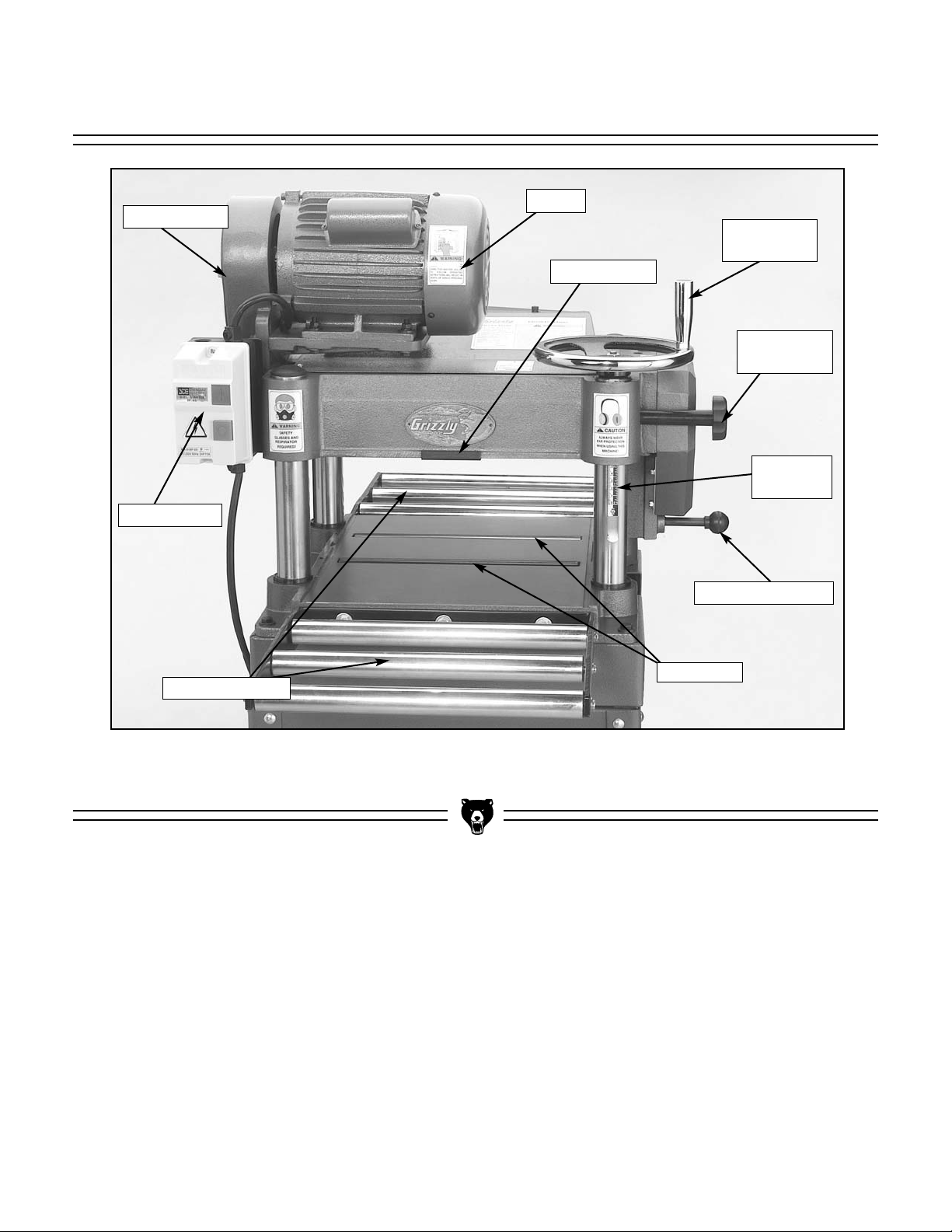
Figure 2. Machine features.
Extension Rollers
Power Switch
V-Belt Cover
Motor
Depth Limiter
Height
Handwheel
Height Lock
Knob
Thickness
Scale
Feed Rate Knob
Bed Rollers
SECTION 4: MACHINE FEATURES
Page 11

G0550/G0551 15" Planer -9-
Work Table: The wood moves through the plan-
er on the work table.
Infeed and Outfeed Rollers: Powered rollers
that move the wood through the planer.
Cutterhead: The cutterhead holds the knives
and spins at 5000 rpm. When wood passes
under the cutterhead, material is removed.
Chip Breaker: Spring loaded fingers or bar that
presses down on the wood in front of the cutterhead. The chip breaker prevents excessive
chipping caused by the knives.
Snipe: A gouge at the end of the board.
Pressure Bar: Rides on the planed surface
behind the cutterhead. Prevents vibration,
chattering and snipe.
Bed Rollers: Located in the work table, the bed
rollers help wood move through the planer.
Dust Hood: Funnels wood dust and chips into
the dust collection system.
Gibs: Metal strips that hold the planer knives in
place.
Gib Bolts: Secures the gib to the knife to keep it
in place.
Common Terms & Definitions
Page 12

-10-
G0550/G0551 15" Planer
The Model G0550/G0551 was carefully packed
when it left our warehouse. If you discover the
machine is damaged after you have signed for
delivery, please immediately call Customer
Service at (570) 546-9663 for advice.
Save the containers and all packing materials for
possible inspection by the carrier or its agent.
Otherwise, filing a freight claim can be difficult.
When you are completely satisfied with the condition of your shipment, you should inventory the
parts.
The purpose of this section is to guide you
through the required steps to get your machine
out of its packaging and into operating condition.
Wear safety glasses during the entire set up
process!
This machine presents
serious injury hazards
to untrained users. Read
through this entire manual to become familiar
with the controls and
operations before starting the machine!
Figure 3. G0550 planer unit.
The Model G0550 comes with an open stand that
requires assembly, and the Model G0551 comes
assembled on a closed cabinet stand.
The following is an inventory of the parts for your
new Model G0550/G0551 Planer.
Parts Inventory
Unpacking
About This Section
SECTION 5: SET UP
Page 13
G0550/G0551 15" Planer -11-
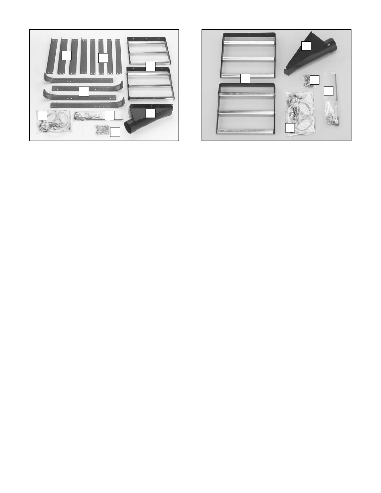
G0550 Loose Parts
DESCRIPTION QTY
A. Extension Rollers ......................................2
B. Dust Port ....................................................1
C. Stand Hardware Bag..................................1
— Carriage Bolts
5
⁄16"-18 x 1⁄2"..................32
— Hex Nuts
5
⁄16"-18 ..................................36
— Flat Washers
5
⁄16" ................................36
— Lock Washer
5
⁄16" ..................................4
— Hex Bolts
5
⁄16"-18 x 1" ............................4
D. Tool Bag ....................................................1
— Handwheel Handle ................................1
— Combo Wrench 8/10mm ......................1
— Combo Wrench 12/14mm ....................1
— Allen Wrench 6mm................................1
— Allen Wrench 5mm................................1
— Allen Wrench 4mm................................1
— Allen Wrench 3mm................................1
— Knife Jig Shaft ......................................1
— Knife Jig Feet ........................................2
— E-Clips 9mm..........................................4
E. Handwheel Bag..........................................1
— Handwheel ............................................1
— High/Low Label......................................1
— Flat Washer 10mm................................1
— Hex Nut M10-1.5 ..................................1
Extension Roller Hardware Bag ................1
— Hex Bolt M8-1.25 x 20 ..........................6
— Flat Washer 8mm..................................6
— Setscrew M8-1.25 x 12 ........................6
Dust Port Hardware Bag............................1
— Phillips Head Screw M6-1.0 x 12 ..........6
F. Legs ..........................................................4
G. Lower Braces ............................................4
H. Predrilled Upper Braces ............................4
G0551 Loose Parts
DESCRIPTION QTY
A. Dust Port ....................................................1
B. Extension Roller Hardware Bag ................1
— Hex Bolts M8-1.25 x 20 ........................6
— Flat Washers 8mm ................................6
— Setscrews M8-1.25 x 12........................6
C. Tool Bag ....................................................2
— Handwheel Handle ................................1
— Combo Wrench 8/10mm ......................1
— Combo Wrench 12/14mm ....................1
— Allen Wrench 6mm................................1
— Allen Wrench 5mm................................1
— Allen Wrench 4mm................................1
— Allen Wrench 3mm................................1
— Knife Jig Shaft ......................................1
— Knife Jig Feet ........................................2
— E-Clips 9mm..........................................4
D. Handwheel Bag..........................................1
— Handwheel ............................................1
— High/Low Label......................................1
— Flat Washer 10mm................................1
— Hex Nut M10-1.5 ..................................1
Foot Hardware Bag....................................1
— Foot ......................................................4
— Hex Nut M8-1.25 ..................................4
Dust Port Hardware Bag............................1
— Phillips Head Screw M6-1.0 x 12 ..........6
E. Extension Rollers ......................................2
Figure 5. G0551 loose parts.
D
E
C
B
A
Figure 4. G0550 loose parts.
H
D
F
E
C
B
A
G
Page 14
-12-
G0550/G0551 15" Planer
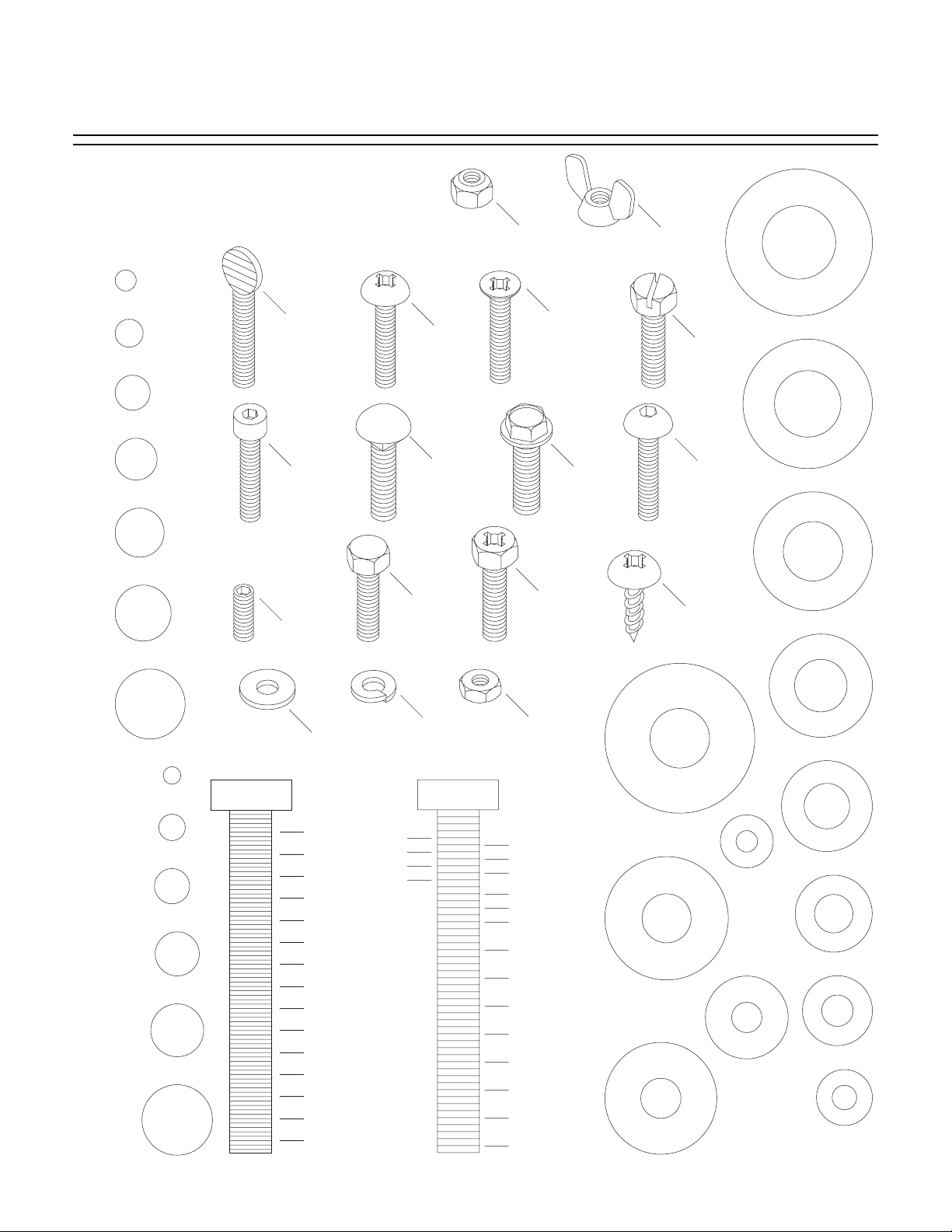
Hardware Recognition Chart
USE THIS CHART TO MATCH UP
HARDWARE DURING THE ASSEMBLY
PROCESS!
#
10
1
⁄4''
Thumb
Screw
Phillips
Head
5
⁄16''
3
⁄8''
7
Cap
Screw
⁄16''
Screw
Carriage
Bolt
Hex
1
⁄2''
Setscrew
5
⁄8''
Head
Bolt
Lock
Washer
MEASURE BOLT DIAMETER BY PLACING INSIDE CIRCLE
4mm
6mm
5mm
10mm
8mm
15mm
20mm
Washer
1
⁄4''
3
⁄8''
1
⁄2''
5
⁄8''
25mm
10mm
30mm
35mm
40mm
45mm
12mm
LINES ARE 1MM APART
50mm
55mm
60mm
⁄16'' INCH APART
1
65mm
16mm
70mm
75mm
LINES ARE
Lock
Nut
Countersunk
Phillips
Head
Screw
Phillips
Head
Hex
Bolt
Hex
Nut
5
⁄16''
7
⁄16''
9
⁄16''
3
⁄4''
7
⁄8''
1''
11⁄4''
1
⁄2''
1
3
⁄4''
1
2
1
⁄4''
2
1
⁄2''
2
3
⁄4''
2
3
D
I
A
R
S
W
M
E
T
⁄8''
9
R
D
⁄16''
1
⁄2''
E
R
I
A
M
E
T
E
R
D
I
A
M
E
T
E
R
5
R
E
E
H
Flange
Bolt
Wing
Nut
Slotted
Screw
Button
Head
Screw
Phillips
S
A
W
E
H
H
S
A
W
A
Head
Sheet
Metal
Screw
D
I
A
R
12mm
D
I
A
D
I
A
M
R
M
E
M
E
T
E
R
D
I
A
R
M
E
H
E
S
T
E
A
R
W
4mm
E
T
E
R
D
I
A
R
M
E
E
H
T
S
E
A
R
W
6mm
T
E
A
S
S
W
H
A
S
A
E
H
E
W
E
H
W
R
10mm
R
8mm
WASHERS ARE MEASURED BY THE INSIDE DIAMETER
D
I
A
R
W
H
S
A
M
E
T
7
⁄16''
E
R
D
I
R
A
M
E
W
H
S
E
3
T
⁄8''
E
R
D
I
A
R
M
E
E
5
T
⁄16''
E
A
R
W
D
I
A
R
M
E
H
E
1
S
⁄4''
T
A
E
R
W
D
I
R
A
E
M
H
E
S
T
A
E
R
W
#
10
E
H
S
A
Page 15

G0550/G0551 15" Planer -13-
The unpainted surfaces are coated with a waxy
oil to protect them from corrosion during shipment. Remove this protective coating with a solvent cleaner or citrus-based degreaser such as
Grizzly’s G7895 Degreaser. To clean thoroughly,
some parts may need to be removed. For opti-
mum performance from your machine, make
sure you clean all moving parts or sliding
contact surfaces that are coated. Avoid chlo-
rine-based solvents as they may damage painted
surfaces should they come in contact.
Gasoline and petroleum
products have low flash
points and could explode
if used to clean machinery. DO NOT use gasoline or petroleum products to clean the machinery.
Unsupervised children
and visitors inside your
shop could receive serious personal injury.
Ensure child and visitor
safety by keeping all
entrances to the shop
locked at all times. DO
NOT allow unsupervised
children or visitors in the
shop at any time.
Floor Load
The Model G0550 weighs 410 lbs and has a 25"
x 25" footprint. The Model G0551 weighs 450 lbs
and has a 21" x 21" footprint. Most commercial
floors are suitable for the machine. Some residential floors may require additional reinforcement to support both the machine and operator.
Working Clearances
Consider existing and anticipated needs, size of
material to be processed through each machine,
and space for auxiliary stands, work tables or
other machinery when establishing a location for
the machine. See Figure 6 for the overall dimensions of the Model G0550/G0551.
Figure 6. Overall machine dimensions.
48"
28"
Smoking near solvents
could ignite an explosion
or fire and cause serious
injury. DO NOT smoke
while using solvents.
Many of the solvents
commonly used to clean
machinery can be toxic
when inhaled or ingested. Lack of ventilation
while using these solvents could cause serious personal health risks
or fire. Take precautions
from this hazard by only
using cleaning solvents
in a well ventilated area.
Clean UpSite Considerations
Page 16
-14-
G0550/G0551 15" Planer
Loose hair and clothing
could get caught in
machinery and cause
serious personal injury.
Keep loose clothing
rolled up and long hair
tied up and away from
machinery.
Sharp edges on metal
parts may cause personal injury. Examine the
edges of all metal parts
before handling.
This section covers the basic assembly and
adjustment instructions needed to begin operation. Complete the assembly in the order provided in this manual and then read the remaining
portion of the manual before attempting any type
of operation.
Your safety is important! Please follow the
warnings below during this entire section:
Disconnect power to
the machine during the
entire assembly
process. Failure to do
this may result in serious personal injury.
Components and Hardware Needed: Qty
Legs ..............................................................4
Lower Braces ................................................4
Predrilled Upper Braces ..............................4
Carriage Bolts
5
⁄16"-18 x 1⁄2" ........................32
Hex Nuts
5
⁄16"-18..........................................32
Flat Washers
5
⁄16" ........................................32
Tools Needed:
12/14mm Combo Wrench ............................1
Note—The following steps are for the G0550
only.
To assemble the open stand:
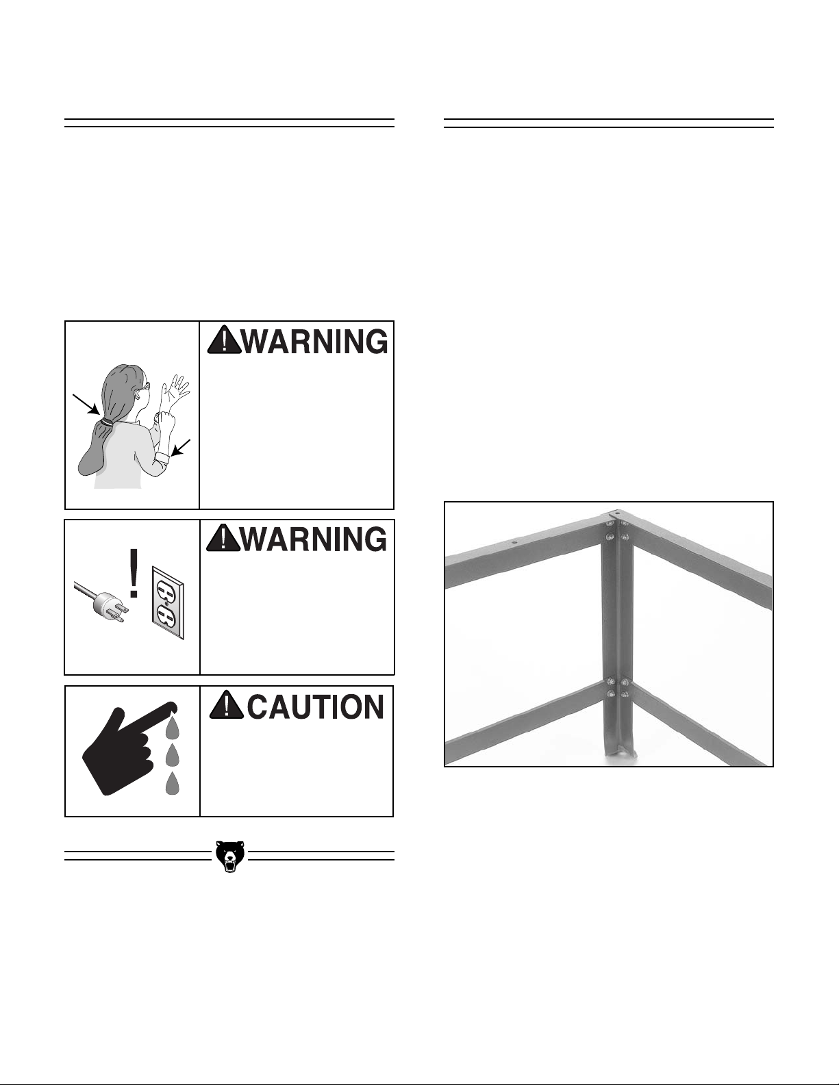
1. Connect the lower and upper braces to the
legs of the stand with the carriage bolts, hex
nuts and flat washers. See Figure 7.
Figure 7. Upper and lower braces
connected to leg.
G0550 Open Stand Beginning Assembly
Page 17
G0550/G0551 15" Planer -15-
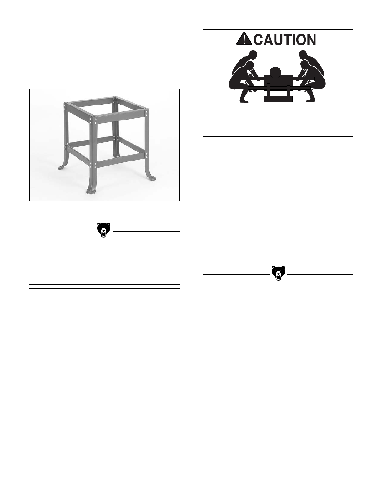
Figure 8. Assembled stand.
Components and Hardware Needed: ....Qty
Planer Unit ....................................................1
Assembled Stand ..........................................1
Hex Bolt
5
⁄16"-18 x 1" ......................................4
Hex Nut
5
⁄16"-18 ..............................................4
Flat Washer
5
⁄16" ............................................4
Lock Washer
5
⁄16"............................................4
Tools Needed:
12/14mm Combo Wrench ..............................2
Strong Persons ..............................................4
To mount the planer:
1. Do not connect the planer to a power
source!
2. Place two 2x4 boards under the cutterhead
of the planer unit. Note—Make sure that the
boards are long enough so that they protrude
from the planer at least 16" on each side.
2. Connect the remaining legs and braces
together. Finger tighten the carriage bolts
that connect the legs to the upper braces.
The finished stand assembly should look like
Figure 8.
3. Have one person on each end of each 2x4
and carefully lift the planer unit onto the
stand.
4. Line up the holes in the corners of the stand
with the holes under the planer unit.
5. Attach the planer to the stand with the four
hex bolts, 4 hex nuts, and 8 washers.
6. Tighten down the carriage bolts on the upper
half of the stand that were finger tightened in
the previous section.
The planer unit represents a heavy load at
400 pounds. Seek assistance before
mounting the planer.
Mounting Planer
(G0550)
Page 18

-16-
G0550/G0551 15" Planer
Figure 10. Installing handwheel.
Components and Hardware Needed: ....Qty
Handwheel ....................................................1
Handwheel Handle ........................................1
Hex Nut M10-1.5............................................1
Flat Washer 10mm ........................................1
High/Low Label ..............................................1
Tools Needed:
12/14mm Combo Wrench ..............................1
The handwheel is used to raise and lower the
planer cutterhead.
To install the handwheel:
1. Do not connect the planer to a power
source!
2. Place the handwheel over the keyed shaft
shown in Figure 10. Make sure the keyway
in the handwheel lines up with the key in the
shaft.
3. Secure the handwheel with the hex nut and
washer.
4. Attach the handle to the outer edge of the
handwheel.
5. Install the High/Low label around the hex nut.
Key
Figure 9. Dust port installed.
Handwheel
Components and Hardware Needed: ....Qty
Dust Port ........................................................1
Phillips Head Screw M6-1 x 12......................6
Tools Needed:
Phillips Head Screwdriver ..............................1
It is important to install a dust collection system to
the dust port.
To install the dust port:
1. Do not connect the planer to a power
source!
2. Place the dust port above the outfeed table.
See Figure 9.
3. Secure the dust port with the Phillips head
screws provided.
Dust Port
Page 19

G0550/G0551 15" Planer -17-
Figure 13. Checking extension roller alignment..
Figure 12. Bed roller.
5. Loosen the bed roller setscrews and turn the
eccentric shaft so the table rollers are
beneath the table surface. See Figure 12.
6. Use a straightedge to check table-to-extension roller alignment as shown in Figure 13.
7. Adjust the leveling setscrews shown in
Figure 11 if the table and extension rollers
are not flush.
Components and Hardware Needed: Qty
Extension Rollers ..........................................2
Tools Needed:
12/14mm Combo Wrench ..............................1
Allen Wrench 4mm ........................................1
To install the extension rollers:
1. Do not connect the planer to a power
source!
2. Remove the three hex bolts and washers
from below the outfeed and infeed tables.
3. Position the extension rollers over the holes.
4. Finger-tighten the hardware removed in step
2 to secure the extension rails to the planer
as shown in Figure 11.
Figure 11. Extension rollers.
Hex Bolts
Level Adjust
Setscrews
Setscrews
Extension Rollers
Page 20

-18-
G0550/G0551 15" Planer
Figure 14. Knife setting jig.
Components and Hardware Needed: Qty
Knife Jig Shaft ................................................1
Knife Jig Feet..................................................2
E-Clips 9mm ..................................................4
To assemble the knife setting jig:
1. Snap one of the E-clips over the notch on
one end of the knife setting shaft.
2. Slide the cast aluminum knife setting jig feet
onto the rod.
3. Snap the other E-clip onto the notch at the
other end of the knife setting jig shaft.
Jig Feet
E-Clip
Jig Shaft
Knife Setting Jig
Page 21

G0550/G0551 15" Planer -19-
Starting the machine:
1. Read the entire instruction manual.
2. Make sure all tools and foreign objects have
been removed from the machine.
3. Review Section 3: Circuit Requirements
(Page 6).
4. Keep your finger on the STOP button at all
times during the test run.
Starting the machine:
Press the START button to turn the machine ON.
The machine should run smoothly with little or no
vibration.
Loose hair and clothing
could get caught in
machinery causing serious personal injury.
Keep loose clothing
rolled up and long hair
tied up and away from
machinery.
Projectiles thrown from
the machine could cause
serious eye injury. Wear
safety glasses during
assembly and operation.
For your convenience, the adjustments listed
below have been performed at the factory and no
further setup is required to operate your machine.
However, because of the many variables
involved with shipping, we recommend that you
at least verify the following adjustments to ensure
the best possible results from your new machine.
Step-by-step instructions on verifying these
adjustments can be found in Section 8: Service
Adjustments.
Factory adjustments that should be verified:
1. Table Adjustment (page 29)
2. Thickness Scale (page 30)
3. Knife Setting (page 32)
4. Chip Breaker (page 33)
5. Feed Roller Height (page 34)
6. Bed Roller (page 35)
7. Feed Roller Pressure (page 36)
8. Chip Deflector (page 37)
Recommended
Adjustments
Start Up
Page 22

-20-
G0550/G0551 15" Planer
Your safety is important! Please follow the
warnings below during this entire section:
Damage to your eyes, lungs, and ears
could result from failure to wear safety
glasses, a respirator, and hearing protection while using this machine.
Loose hair and clothing
could get caught in
machinery and cause
serious personal injury.
Keep loose clothing
rolled up and long hair
tied up and away from
machinery.
There is a cutterhead lock knob on each side of
the planer that must be loosened before adjusting
the height. Once the height has been set, tighten
the lock knobs. See Figure 15.
Figure 15. Cutterhead lock knob.
Lock down the cutterhead with the cutterhead lock knobs before planing or snipe
will occur.
NOTICE
General Cutterhead Locks
SECTION 6: OPERATIONS
Page 23

G0550/G0551 15" Planer -21-
The power feed can be set for two feed rates—16
FPM and 20 FPM. While the planer is running the
feed rate can be changed by pulling the feed control knob (Figure 16). Press the knob in towards
the machine for 20 FPM and pull the knob out for
16 FPM. When the control knob is in the center
position, the power feed is in neutral.
Figure 16. Power feed knob.
Turn the handwheel to raise or lower the cutterhead, according to the workpiece thickness.
Each complete revolution of the handwheel
moves the table by
5
⁄32
" (4mm).
Make sure the height scale is properly adjusted
before making a cut. It is always a good idea to
run a test piece through the planer and compare
the thickness of the workpiece to the scale reading.
No list of safety guidelines can be complete.
Every shop environment is different. Always
consider safety first, as it applies to your
individual working conditions. Use this and
other machinery with caution and respect.
Failure to do so could result in serious personal injury, damage to equipment, or poor
work results.
Figure 17. Depth limiter.
The depth limiter, shown in Figure 17, controls
the maximum depth of cut to
1
⁄8". To avoid
mechanical damage to the planer and workpiece
do not remove the depth limiter.
To avoid mechanical damage to the planer,
do not remove the depth limiter.
NOTICE
Depth Limiter
HandwheelPower Feed
Page 24

-22-
G0550/G0551 15" Planer
The species of wood, as well as its condition,
have a dramatic effect on planing ability. The
harder the wood (as illustrated by its shear
strength), the more difficult it will be to plane. A
brief listing of common hard and soft woods in
relation to their shear strengths and planing difficulty is listed below.
Type Shear (PSI)
Black Locust 2,480
Sugar Maple 2,330
Pecan Hickory 2,080
White Oak 2,000
White Ash 1,950
Black Cherry 1,700
American Elm 1,510
Black Walnut 1,370
Red Alder 1,080
Basswood 980
Cottonwood 930
Increasing
Difficulty
Type Shear (PSI)
Western Larch 1,410
Tamarack 1,280
Douglas Fir 1,160
Alaska Cedar 1,130
Sitka Spruce 1,150
Sugar Pine 1,050
Cypress 1,000
Redwood (OG) 940
Red Cedar 860
White Pine 850
Balsam Fir 710
Increasing
Difficulty
Figure 18. Anti-kickback fingers.
The anti-kickback fingers hang from a rod suspended across the front of the cutterhead casting.
Check the fingers to ensure that they swing freely
and easily. See Figure 18.
DO NOT apply oil or other lubricants to the
anti-kickback fingers. Oil or grease will
attract dust and restrict movement of the
fingers, which could result in damage to
your workpiece, the planer, or possibly
serious injury to the operator.
Anti-kickback Fingers
Wood Species Anti-Kickback
Page 25

G0550/G0551 15" Planer -23-
Always disconnect
power to the machine
before performing maintenance. Failure to do
this may result in serious
personal injury.
Regular periodic maintenance on the Model
G0550/G0551 will ensure optimum performance.
Make a habit of inspecting the machine each time
you use it.
Before each use, look for the following conditions:
1. Loose mounting bolts.
2. Worn switch.
3. Worn or damaged cords and plugs.
4. Damaged V-belt.
5. Any other condition that could hamper the
safe operation of this machine.
The table and other non-painted surfaces on your
machine should be protected against rust and pitting. Wiping the table clean after every use
ensures that moisture from wood dust does not
remain on bare metal surfaces.
Tables can be kept rust-free with regular applications of products like SLIPIT
®
or Boeshield®T-9.
For long term storage you may want to consider
products like Kleen Bore's Rust Guardit™.
Loose hair and clothing
could get caught in
machinery and cause
serious personal injury.
Keep loose clothing
rolled up and long hair
tied up and away from
machinery.
Your safety is important! Please follow the
warnings below during this entire section:
Projectiles from the
machine could cause
serious eye injury. Wear
safety glasses at all
times.
Table
GeneralMaintenance Safety
SECTION 7: MAINTENANCE
Page 26

-24-
G0550/G0551 15" Planer
To ensure optimum power transmission from the
motor to the blade, the V-belts must be in good
condition (free from cracks, fraying and wear).
Check the V-belts at least every 3 months; more
often if the planer is used daily.
Make sure that the motor pulley and cutterhead
pulley are aligned and the V-Belts are properly
tensioned.
To align the V-Belt:
1. Disconnect the machine from the power
source!
2. Remove the V-Belt cover.
3. Loosen the bolts that mount the motor to the
motor mount bracket.
4. Adjust the position of the motor until the pulleys are in line, and check the alignment with
a straightedge as shown in Figure 19.
Figure 19. Checking pulley alignment.
Figure 20. Tensioning Belt.
Squeeze the V-Belts at their midpoints with moderate finger pressure. You should be able to
deflect each V-Belt about 3/4". Belts will rarely be
too tight, but will sometimes be too loose.
To tension the V-Belt:
1. Disconnect the machine from the power
source!
2. Insert a wooden lever between the motor
mount and the top of the planer as shown in
Figure 20.
Loosen These Bolts
3. Loosen the two bolts that hold the motor pul-
ley assembly to the planer (Figure 19).
4. Lift the motor assembly with the wooden
lever until the belt is tensioned correctly.
5. Hold the motor in place and secure the bolts
loosened in step 3.
6. Squeeze the belts to check the tension and
repeat steps 2-5 if necessary.
V-Belts
Page 27

G0550/G0551 15" Planer -25-
The gearbox is located just behind the handwheel
on the right side of the planer. The gearbox transfers power from the belt-driven cutterhead to the
power feed rollers. The two-speed transmission
is controlled by a push/pull lever on the right side
of the planer. When engaged, the power feed
rollers will move lumber through the planer at
either 16 or 20 feet-per-minute. The center lever
position is neutral.
To inspect the gearbox:
1. Loosen the socket head cap screw on the
gearbox cover, and gently pull the cover off
the roll pins that hold it in place.
2. Check the bolts that hold the sprockets in
place. Inspect the drive chains to ensure that
the retaining clips are in place. Replace the
clips if necessary. See Figure 21.
Figure 21. Gearbox.
Since all bearings are sealed and permanently
lubricated, simply leave them alone until they
need to be replaced. DO NOT lubricate them.
The following is a list of features and parts
that need lubrication:
Columns/Lead Screws—The four columns
should be lubricated with light machine oil once a
week. The four lead screws should be lubricated
with general purpose grease once a month. See
Figure 22.
Figure 22. Columns and lead screws.
Column
Lead screw
LubricationGearbox
Page 28

-26-
G0550/G0551 15" Planer
Figure 24. Gearbox oil drain point.
Figure 23. Gearbox fill point.
Worm Gear—The worm gear should be inspect-
ed monthly and lubricated when needed.
Remove the worm gear box to inspect. See parts
diagram for location.
Chain—The table height adjustment chain
should be inspected monthly and lubricated when
needed. A good quality bicycle chain lubricant
works well for periodic lubrication.
Gear Box—Gear box oil should be drained after
the first 20 hours of operation. See Figure 23 &
24. Replace with 80W-90 gear oil. Inspect levels
periodically and change yearly. Replace gear oil
more frequently under heavy use. Fill until oil
reaches the top of the filler plug port for correct oil
level.
Drive Chain—The drive chain should be inspected and lubricated monthly. Check the sprocket,
the chain and the cotter pin during inspection.
Use a general purpose grease. Some chains will
have master links instead of cotter pins.
Feed Rollers—The infeed/outfeed pressure
setscrews double as lubrication ports for the
rollers. See Figure 25. Add 1-2 drops of light
machine oil to all ports before each use. Daily
lubrication of the feed rollers is crucial to the operation of your planer. Lubricate before start-up.
Apply a light oil, making sure that the lubricant
penetrates the bearing.
Figure 25. Feed roller lubrication points.
Page 29

G0550/G0551 15" Planer -27-
The species of wood, as well as condition, will
affect planing ability. The harder the wood, the
more difficult it will be to plane. Below, we have
included below, a list of wood characteristics you
may encounter when planing. The following
descriptions of defects will give you some possible answers to problems you may encounter
while planing different materials. Possible solutions follow the descriptions.
Chipped Grain—Usually a result of cutting
against the grain, or planing wood with knots or
excessive amount of cross grain. Chipped grain
can also be caused by dull knives or misaligned
chipbreaker. Often, chipped grain can be avoided
by slowing down the feed rate and by taking shallow cuts. If those options do not work, inspect
your lumber and determine if its grain pattern is
causing the problem. If the wood does not show
substantial crossgrain, inspect your knives for
sharpness and inspect the chipbreaker for proper
alignment. See the Adjustment Section.
Fuzzy Grain—Usually caused by surfacing lumber with too high of a moisture content.
Sometimes fuzzy grain is a characteristic of some
woods, such as basswood. Fuzzy grain can also
be caused by dull knives or an incorrect grinding
bevel. Check with a moisture meter. If moisture is
greater than 20%, sticker the wood and allow to
dry. Otherwise, inspect knife condition.
Glossy Surface—Usually caused by dull knives
taking shallow cuts at a slow feed speed. Surface
gloss will usually be accompanied by overheating. Often, lumber will be scorched and eventually damage to knives will occur. If knives are sharp
on inspection, increase feed speed or cutting
depth.
Snipe—Occurs when board ends have more
material removed than the rest of the board.
Usually caused when one or both of the bed
rollers are set too high. Can also be caused by
the chipbreaker or pressure bar being set too
high. However, small amount of snipe is
inevitable.
Snipe can be minimized by proper adjustment of
the planer components, but complete removal of
snipe is extremely unlikely. More likely, you will
be able to reduce it to a tolerance of .002". If
snipe under that level is a problem, consider planing lumber longer than your intended work length
and cut off the excess after planing is completed.
Uneven Knife Marks—Uneven knife marks can
occur when the chipbreaker is set too high.
Inspect cutterhead bearings if re-adjustment of
the chipbreaker fails to remedy the situation.
Chatter Marks—Usually caused by incorrect
chipbreaker and pressure bar setting heights.
Chatter marks can also be caused by running a
narrow wood piece through the planer at either
the right or left end of the cutterhead. Chatter, like
uneven knife marks, will show in the form of a
''washboard'' look. Chatter marks are more likely
to be inconsistent in appearance than uneven
knife marks.
Wavy Surface—Caused by poor knife height
adjustment, a wavy surface appears when one
knife is taking deeper cuts than the rest of the
knives. Remedy by resetting the knives to a tolerance within 0.003" of one another.
Pitch & Glue Build-up—Glue and resin build-up
on the rollers and cutterhead will cause overheating by decreasing cutting sharpness while
increasing drag in the feed mechanism. The
result can include scorched lumber as well as
uneven knife marks and chatter.
Chip Marks—Occur when chips are not properly
expelled from the cutterhead. The knives catch
the chips and drag them across the lumber being
planed. Chips tend to be random and non-uniform (as compared to chipped grain). Can be
caused by exhaust blockage or too much room
between the cutterhead and chip deflector. Using
a dust collection system in combination with the
planer can help reduce chip marks. Inspect the
chip deflector and readjust (as described earlier
in the text).
Planing Difficulties
Page 30

-28-
G0550/G0551 15" Planer
Always disconnect
power to the machine
before performing service adjustments. Failure
to do this may result in
serious personal injury.
This section is designed to help the operator with
adjustments that were made at the factory and
that might also need to be made during the life of
the machine.
This section is provided for your convenience—it
is not a substitute for the Grizzly Service
Department. If any adjustments arise that are not
described in this manual, then feel free to call the
Grizzly Service Department at (570) 546-9663.
Similarly, if you are unsure of how to perform any
procedure in this section, the Grizzly Service
Department will be happy to guide you through
the procedures or help in any other way.
Before attempting to adjust the table, you will
need to construct a gauge block. See Figure 26.
Do not use common 2x4 material. Use a hard
wood material like maple or oak. A pattern for this
gauge block has been provided for you on page
48 of this manual.
A good alternative is to use a Rotocator Figure
27. Use the Rotocator whenever the instructions
call for use of the gauge block or feeler gauge.
Refer to the current Grizzly catalog for rotocators.
Figure 26. Gauge block specifications.
Figure 27. Rotocator.
Gauge Blocks
About Service
SECTION 8: SERVICE ADJUSTMENTS
Page 31

G0550/G0551 15" Planer -29-
It is important that the cutterhead is parallel to the
table to plane stock perfectly square.
To check the table alignment:
1. Disconnect the machine from the power
source!
2. Place the gauge block on the table under
one end of the cutterhead.
3. Turn the handwheel to raise the table until
the block barely touches the cutterhead
body. The block should not be touching
the knives. See Figure 28.
4. Slide the block toward the opposite side of
the cutterhead. Use a feeler gauge to measure the width of the gap, if any, between the
top of the block and the bottom of the cutterhead. If there is a gap, make a note, reading
the distance from the feeler gauge.
5. If the block wedges tightly between the table
and cutterhead when shifting from one side
to the other, repeat steps 1 through 3 above,
but start from the opposite end of the cutterhead.
Figure 28. Setting the outfeed table height.
— If the gap difference from one side to the
other is equal to or less than 0.004", no
further adjustment is necessary.
Figure 29. Cap screws for column adjustment.
— If the gap difference from one side to the
other is greater than 0.004", but less than
0.016", go to step 5.
If the gap difference from one side to the other is
greater than 0.016", the table raising chain under
the planer base will need to be adjusted. Please
call our Customer Service number for chain
adjustment instructions.
To adjust for gap differences:
6. Determine which side of the table must be
raised to correct the gap.
7. Locate the two cap screws in the table cast-
ing for each of the columns. See Figure 29.
Loosen both sets of cap screws for each column on the side you wish to adjust.
8. Push down or pull up the table in the desired
direction. Hold the table in position and
retighten the cap screws.
9. Recheck the table to cutterhead parallelism
again. Repeat steps 1- 8 until the deviation
is less than 0.004".
Table Adjustment
Page 32

-30-
G0550/G0551 15" Planer
The thickness scale, located below the handwheel, can be adjusted for accuracy. However,
material must be run through the machine to
adjust the thickness scale. Make certain you have
followed the directions in the Operations Section
for test running before attempting to make these
adjustments.
To adjust the scale:
1. Adjust the cutterhead height to the approxi-
mate thickness of your test lumber. Measure
the lumber with calipers to determine its
exact thickness.
2. Move the cutterhead to
1
⁄16" under the thickness of your lumber and feed your test board
through the planer.
3. Turn the handwheel one half rotation and run
the board through once more. Turn the board
over and repeat.
Figure 30. Screw for column adjustment.
4. Measure the board again and compare your
results with the scale. If there is a discrepancy, loosen the scale adjustment screw and
correct the position. See Figure 30.
Thickness Scale
Page 33

G0550/G0551 15" Planer -31-
5. The variation between one side and the other
should not be greater than 0.004". Repeat
steps 1-4 on the other two knives. Again, the
variation between all three knives should not
be greater than 0.004".
Once you have completed inspection on all three
knives, you will able to determine whether or not
there is a need to adjust the knives in the cutterhead. Proceed to the appropriate section,
depending upon whether you are using the jack
screws or the springs.
Figure 31. Using the feeler gauge to
measure the gap.
The Model G0550/G0551 Planer has a threeknife cutterhead. The cutterhead is located in the
head casting and rotates on two sealed bearings.
No lubrication is needed for the life of the bearings.
Because of normal use and wear, the knives
must be periodically sharpened, replaced or
adjusted. Adjustment from the factory must also
be checked prior to use due to possible movement during shipment.
To inspect the knives:
1. Disconnect the machine from the power
source!
2. Lower the table and place the gauge block or
a Rotocator under one end of the cutterhead.
3. Remove the V-Belt cover and carefully rotate
the belts to turn the cutterhead until the first
knife is at bottom dead center. Adjust the cutterhead height until the knife barely touches
the top of gauge block. Note—Rock the cut-
terhead back and forth to determine bottom
dead center.
4. Slide the gauge block to the opposite side of
the cutterhead and check the same knife,
rocking back and forth to determine bottom
dead center.
— If the knife does not contact the gauge
block, use a feeler gauge to determine
the difference between one side and the
other. See Figure 31.
— If the knife bottoms out on the gauge
block, repeat steps 1-3, but start on the
opposite side of the cutterhead.
When making adjustments, all three knives
must be adjusted the same. DO NOT adjust
one knife without adjusting the others as
well. Improper knife height adjustment can
result in damage to knives, poor planer performance and possible operator injury.
Always adjust the thickness scale after
adjusting the knives.
NOTICE
Knife Inspection
Page 34

-32-
G0550/G0551 15" Planer
Figure 32. Proper knife setting jig placement.
For the best results, it is best to have planer
knives sharpened by a professional sharpening
service which has the grinding and measurement
equipment to assure that the knife cutting geometry is maintained at optimum levels. Knife sharpening is a procedure that requires some care and
precision, otherwise, a set of blades can be easily ruined. Knives should always be ground as a
set so they can be properly matched. Unequal
material removal can result in an unbalanced cutterhead which can affect not only planing surface
quality but ultimately the life of the cutterhead
bearings.
Your planer knives can be sharpened by a blade
hone. See the “Aftermarket Accessories” subsection at the back of this manual for more information.
The process of setting the knives in the cutterhead will come into play whenever you sharpen
or replace, or after determining that setting is necessary during the initial setup.
The knives lock into the cutterhead with wedge
type gibs. Springs under each knife provide an
upward pressure to help ease the setting
process. Jack screws under the knives allow fine
tuning to help in the setting process.
To set the knives:
1. Disconnect the machine from the power
source!
2. Remove the upper cover to expose the cut-
terhead.
3. Choose a knife to begin with and loosen the
gib bolts just enough until the springs push
the knife upward.
Figure 32 illustrates the features of the cutterhead that are mentioned in this section.
Knife SettingKnife Sharpening
Page 35

G0550/G0551 15" Planer -33-
Figure 34. Tightening gib bolts in cutterhead.
5. While holding the position of the knife setting
jig, adjust the jack screws, located on each
end of the knife, until they make contact with
the bottom of the knife.
6. While holding the position of the knife setting
jig, tighten the gib bolts down again in the
cutterhead (Figure 34). Tighten the bolts
evenly from the middle, working toward the
ends.
7. Repeat these steps for the other two knives.
The chip breaker is located on the top side of the
planer and extends down around the front of the
cutterhead. Its function is to prevent tear-out or
deep, unregulated gouging as the knives remove
material. The chip breaker works by breaking the
woodchips as they are being cut by the cutterhead. The chip breaker also deflects and expels
the woodchips away from the surface of the
board and out of the planer.
To check the chipbreaker:
1. Disconnect the machine from the power
source!
2. Ensure that the knives are properly adjusted.
3. Place the gauge block on the table directly
under the cutterhead.
4. Using a 1mm feeler gauge between the
gauge block and the cutterhead, raise the
table until one of the knives just touches the
feeler gauge. Rotate the cutterhead by turning the V-belts to be sure the knife is at bottom dead center.
5. Lock the table by tightening the table lock
knobs.
6. Remove the feeler gauge and slide the
gauge block under the chip breaker. See
Figure 35. The chip breaker should just
touch the top of the gauge block. Slide the
gauge block to the opposite end of the chip
breaker and check it in the same manner.
Figure 33. Proper knife setting jig placement.
4. Place the knife setting jig over the knife on
the cutterhead as shown in Figure 33. The
knife setting jig will push the knife into position in the cutterhead.
Chip Breaker
Page 36

-34-
G0550/G0551 15" Planer
The infeed and outfeed rollers move the lumber
through the planer, and press the lumber flat
against the planer table.
Set the infeed and outfeed rollers to 0.02"-0.04"
below the cutterhead knife edge at bottom dead
center.
To check roller height:
1. Disconnect the machine from the power
source!
2. Lower the table so the gauge block will fit
under one side of the infeed roller.
3. Raise the table until the gauge block barely
touches the infeed roller. See Figure 37. Do
not change the position of the table.
4. Slide the gauge block over so it is under the
edge of one of the knives. Turn the cutterhead until one of the knives is at bottom
dead center over the gauge block.
5. Measure the clearance between the top of
the gauge block and the edge of the knife
with a feeler gauge. Note the measurement
indicated on the feeler gauge.
Figure 35. Gauge block under chip breaker.
Figure 36. Chip breaker height adjustment.
To adjust the chip breaker:
1. Disconnect the machine from the power
source!
2. If an adjustment is necessary, loosen the
locknuts and turn the setscrews. See Figure
36. Stop turning when the bottom of the chip
breaker just touches the gauge block.
3. Tighten both locknuts.
Figure 37. Feed roller height inspection.
Chipbreaker
Infeed Roller
Anti-Kickback
Fingers
Feed Roller Height
Page 37

G0550/G0551 15" Planer -35-
Figure 39. Inspecting bed roller height.
The bed rollers ease stock movement through
the planer. The height of the bed rollers will vary
depending on the types of wood you will be planing. When planing rough stock, set the rollers
slightly high to keep the lumber from dragging
along the bed; however, snipe may be unavoidable. Smooth lumber should be planed with the
rollers set just above the plane of the table. This
will minimize snipe.
To adjust the bed rollers:
1. Ensure that power is disconnected and lay a
high quality straightedge across both table
rollers. Use a try square to keep the straightedge perpendicular to the table.
2. Use a feeler gauge to measure the clearance
between the bottom of the straight edge and
the table. Ideal clearance is between 0.006"
and 0.002". Measure in several places. This
measurement must be consistent across the
entire table. See Figure 39.
6. Repeat steps 1-5 for the opposite side of the
roller. Repeat all steps for the outfeed roller.
Feeler gauge measurement should be between
0.02"- 0.04"on the infeed and outfeed roller at
bottom dead center.
To adjust roller height:
1. Remove the drive chain cover to access the
roller adjustments on the drive chain side of
the planer. A single socket head cap screw
holds the drive chain cover on. The belt side
adjustments are already accessible.
2. Loosen the roller adjustment check nuts and
turn the roller height setscrews to change the
height of the roller as needed. See Figure
38.
3. Check the roller height according to the
above instructions. Continue turning the
setscrew until the roller is properly adjusted.
4. When the roller is set in the correct position,
retighten the check nuts you loosened in
step 2 above.
5. Check your settings one last time and repeat
steps 1-4 if necessary.
Figure 38. Feed roller height adjustment.
Bed Rollers
Page 38

-36-
G0550/G0551 15" Planer
4. Use a wrench to turn the eccentric shafts that
adjust roller height. Stop turning when the
table rollers are at the proper height.
5. Once your roller heights are correct, retighten all the setscrews.
6. Check the height of the table rollers. Repeat
steps 1-5 until the bed rollers are properly
set.
7. Spin the bed rollers to ensure free movement.
Figure 40. Adjusting bed roller height.
3. Loosen the setscrews on both sides of
each bed roller. See Figure 40.
Setscrews
Setscrews
To be effective, the infeed and outfeed rollers
must put pressure on the workpiece as it feeds
through the planer. Too little pressure results in
slipping boards, too much pressure results in
jamming.
Experiment with the best pressure settings for
your work situations. Some rough cut lumber will
feed through with relatively few problems, while
other lumber will have more difficulty.
Adjusting roller pressure does not affect height.
To adjust roller pressure:
1. Disconnect the machine from the power
source!
2. Ensure that knives and feed rollers are set
correctly.
3. Unscrew the three regular pressure
setscrews on top of the planer body. See
Figure 41.
Figure 41. Roller pressure setscrews.
Regular Pressure Setscrews
Light Pressure Setscrew
Feed Roller Pressure
Page 39

G0550/G0551 15" Planer -37-
The chip deflector keeps chips from falling onto
the outfeed roller. It is the orange plastic plate
located under the top cover.
The beveled edge of the chip deflector should be
properly adjusted according to your dust collection setup. However, if the chip deflector is set too
close to the knives, the rotating cutterhead may
pull it in and destroy it.
To adjust the chip deflector:
1. Disconnect the machine from the power
source!
2. Loosen the three deflector mounting bolts.
See Figure 43. Make sure the beveled edge
of the deflector faces the cutterhead.
Figure 43. Chip deflector access.
Chip Deflector
Chipbreaker
Cutterhead
Figure 42. Roller pressure assembly.
Height Setscrew
Pressure Spring
Roller
Pressure Setscrew
Check Nut
— The edge of the chip deflector should be
1
⁄16" away from the knife edge if a dust collection system is not installed on your
planer.
— The edge of the chip deflector should be
1
⁄4" away from the knife edge if a dust collection system is in place on your planer.
3. Tighten the chip deflector mounting bolts and
mount the upper cover back onto the planer.
4. Remove the springs that are in the setscrew
holes. See Figure 42.
5. Check for any dirt or grit, and clean the
springs and setscrews if dirty.
6. Screw the three regular-pressure setscrews
back in until they are flush with the top of the
head casting.
7. Screw the light pressure setscrew (Figure
42) until it is approximately
1
⁄4" above the
head casting. The feed chain applies additional tension to the right side of the outfeed
roller, so the pressure added by the setscrew
need not be as high.
Mounting Bolts
Chip Deflector
Page 40

-38-
G0550/G0551 15" Planer
This section contains the following subsections
for the Model G0550/G0551: aftermarket accessories, data sheets, parts diagrams and list, troubleshooting, wiring diagrams, gauge block
design, and warranty/return information.
If you need parts or help in assembling your
machine, or if you need operational information,
call the service department at (570) 546-9663.
Trained service technicians will be glad to help
you.
If you have any comments regarding this manual,
please write to Grizzly at the address below:
Grizzly Industrial, Inc.
C
/O Technical Documentation
P.O. Box 2069
Bellingham, WA 98227-2069
General
We recommend you keep a copy of our current
catalog for complete information regarding
Grizzly's warranty and return policy. If you need
additional technical information relating to this
machine, or if you need general assistance or
replacement parts, please contact the Service
Department at the location listed below.
Grizzly Industrial, Inc.
1203 Lycoming Mall Circle
Muncy, PA 17756
Phone: (570) 546-9663
Fax: (800) 438-5901
E-Mail: techsupport@grizzly.com
Web Site: http://www.grizzly.com.
SECTION 9: REFERENCE INFO
Page 41

G0550/G0551 15" Planer -39-
Rotocator—Model G1738
The Rotacator® has a
magnetic base and is
used to adjust settings
on any planer. Infeed
and outfeed rollers,
pressure bars, feed-bed
rollers, chipbreaker,etc.,
can be adjusted very
quickly and accurately.
Planer/Jointer Blade Hone—Model G3631
Add a razor hone to your
planer and jointer knives
with this hand-held
sharpening device.
To order any of the aftermarket accessories
below, find the model number in bold and call our
customer service line 24 hours a day at 1-800523-4777.
Replacement Knives—Model G1196
Replace your old planer
knives and get your
machine cutting like new
again with these high
speed steel replacement
knives.
SHOP FOX
®
Mobile Base—Model G8683
Make your planer mobile
with this popular patented mobile base.
Planer Pals—See The Current Grizzly Catalog
For Model #s.
These patented jigs are
remarkably simple to
use an hold knives
securely in place while
you tighten them in the
cutterhead. They also
allow you to shift nicked
knives to avoid replacement or removal.
Aftermarket
Accessories
Page 42

-40-
G0550/G0551 15" Planer
Design Type ....................................................................................................Bench Model
Overall Dimensions:
Table Size....................................................................................................14
7
/8'' x 20''
Height w⁄ Stand ........................................................................................................53''
Overall Length ..........................................................................................................48''
Overall Width............................................................................................................28''
Shipping Weight ................................................................................................460 lbs.
Net Weight ........................................................................................................410 lbs.
Foot Print ........................................................................................................25" x 25"
Crate Size ..................................................................................22
1
⁄2"L x 30"W x 29"H
Capacities:
Maximum Depth of Cut..............................................................................................
1
⁄8''
Maximum Width of Cut ........................................................................................ 14
7
⁄8''
Maximum Cutting Height ........................................................................................6
1
⁄8''
Minimum Stock Thickness........................................................................................
3
⁄16"
Minimum Stock Length ..............................................................................................8"
Cutterhead Speed ........................................................................................5000 RPM
Cuts per Minute ..................................................................................................15,000
Cuts per Inch.................................................................................................... 63 & 78
Feed Speeds ............................................................................................16 & 20 FPM
Construction:
Table ..................................................................................Precision Ground Cast Iron
Infeed Roller ..........................................................................................Spiral Serrated
Outfeed Roller ......................................................................................Machined Steel
Power Transfer to Feed Rollers:........................................................Gearbox & Chain
Cutterhead Assembly ............................................................................................Steel
Cutterhead ............One piece machined shaft; 3 Knife Slots w/ Sealed Ball Bearings
Motor:
Type ............................................................................TEFC Capacitor-Start Induction
Horsepower............................................................................................................2 HP
Phase ⁄ Voltage ............................................................................Single Phase ⁄ 220 V
Amps ......................................................................................................................12A
Cycle ⁄ RPM..................................................................................60 Hertz ⁄ 3450 RPM
Switch........................................................Magnetic With Thermal Overload Protector
Power Transfer to Cutterhead ..................................................................Triple V-Belt
Bearings ............................................Sealed & Permanently Lubricated Ball Bearings
Features:
Stand............................................................................................................Open Style
Roller Extension Tables ................................................................3 Adjustable Rollers
Cutterhead Movement ..................................Handwheel & 4 Chaindriven Leadscrews
Table Locks ..............................................................................................Two Positive
Chip Chute ......................................................................................................4'' Outlet
Bed Rollers ................................................................................................2 Adjustable
Knife Type / Size / Adjustment ........3 HSS / 15" x 1" x
1
⁄8" / Jack-screws and Springs
..........................................................................................Drive Gears Run In Oil Bath
..........................................................................Vertical Scale Calibrations Inch/Metric
Specifications, while deemed accurate, are not guaranteed.
Customer Service #: (570) 546-9663 • To Order Call: (800) 523-4777 • Fax #: (800) 438-5901
GRIZZLY MODEL G0550 15" PLANER
MACHINE DATA
SHEET
Page 43

G0550/G0551 15" Planer -41-
Design Type ....................................................................................................Bench Model
Overall Dimensions:
Table Size....................................................................................................14
7
/8'' x 20''
Height w⁄ Stand ........................................................................................................53''
Overall Length ..........................................................................................................48''
Overall Width............................................................................................................28''
Shipping Weight ................................................................................................560 lbs.
Net Weight ........................................................................................................450 lbs.
Foot Print ........................................................................................................21" x 21"
Crate Size ................................................................................30
3
⁄4"L x 30"W x 481⁄2"H
Capacities:
Maximum Depth of Cut..............................................................................................
1
⁄8''
Maximum Width of Cut ........................................................................................ 14
7
⁄8''
Maximum Cutting Height ........................................................................................6
1
⁄8''
Minimum Stock Thickness........................................................................................
3
⁄16"
Minimum Stock Length ..............................................................................................8"
Cutterhead Speed ........................................................................................5000 RPM
Cuts per Minute ..................................................................................................15,000
Cuts per Inch.................................................................................................... 63 & 78
Feed Speeds ............................................................................................16 & 20 FPM
Construction:
Table ..................................................................................Precision Ground Cast Iron
Infeed Roller ..........................................................................................Spiral Serrated
Outfeed Roller ......................................................................................Machined Steel
Power Transfer to Feed Rollers:........................................................Gearbox & Chain
Cutterhead Assembly ............................................................................................Steel
Cutterhead ............One piece machined shaft; 3 Knife Slots w/ Sealed Ball Bearings
Motor:
Type ............................................................................TEFC Capacitor-Start Induction
Horsepower............................................................................................................3 HP
Phase ⁄ Voltage ............................................................................Single Phase ⁄ 220 V
Amps ......................................................................................................................18A
Cycle ⁄ RPM..................................................................................60 Hertz ⁄ 3450 RPM
Switch........................................................Magnetic With Thermal Overload Protector
Power Transfer to Cutterhead ..................................................................Triple V-Belt
Bearings ............................................Sealed & Permanently Lubricated Ball Bearings
Features:
Roller Extension Tables ................................................................3 Adjustable Rollers
Cutterhead Movement ..................................Handwheel & 4 Chaindriven Leadscrews
Table Locks ..............................................................................................Two Positive
Chip Chute ......................................................................................................4'' Outlet
Bed Rollers ................................................................................................2 Adjustable
Knife Type / Size / Adjustment ........3 HSS / 15" x 1" x
1
⁄8" / Jack-screws and Springs
..........................................................................................Drive Gears Run In Oil Bath
..........................................................................Vertical Scale Calibrations Inch/Metric
..................................................................................Powder Coated Paint on Cabinet
Specifications, while deemed accurate, are not guaranteed.
Customer Service #: (570) 546-9663 • To Order Call: (800) 523-4777 • Fax #: (800) 438-5901
GRIZZLY MODEL G0551 15" PLANER
MACHINE DATA
SHEET
Page 44

-42- G0550/G0551 15" Planer
10-4
17
10-3
164
30
10-5
32
10-1
26
22
145
34
53
25
24
51
10-2
23
22
50
144
162
13
33
19
27
49
22
29
48
38
21
28
47
37
46
144
45
36
44
13
163
35
13
170
13
68
67
172
171
69
43
42
65
166
64-1
56
20
72
57
41
40
64
40
48
63
39
71
62
61
60
54
55
73
56
52
74
75
57
59
67
166
58
78
56
57
45
704956
3
63
45
77
76
59
74
75
74
146
73
57
52-3
52-1
147
148
52-4
52-2
13
84
83
82
81
67
79
80
166
95
66
93
89
92
94
86
91
90
105
103
89
104
102
101
100
99
109
108
89
96
98
107
13
97
96
10
110
157
13
11
160
5
15
8
6
4
6
4
6
4
7
5
15
2
1
18
14
16
13
12
82
88
87
83
9
85
Page 45

G0550/G0551 15" Planer -43-
137
166
106
111
133
134
114
112
111
3
135
115
22
129
113
136
130
131
22
132
3
20
55
119
118
117
124
125
123
122
22
121
165
120
169
15
118
117
116
165
126
167
127
137
128
168
31
30
116
55
Page 46

-44-
G0550/G0551 15" Planer
142
141
140
G0551 Stand
149
150
151
139
156
138
17
143
152
153
154
173
174
175
176
177
190 184
183
180
186
185
188
187
178
179
185
190
188
187
187
190
181186
187
190
182
186
180
186
G0550 Stand
191
192
193
Page 47

G0550/G0551 15" Planer -45-
1 P0550001 PULLEY COVER
2 PVM27 V-BELT M-27 3L270
3 PB09M HEX BOLT M8-1.25 X 20
4 PB01M HEX BOLT M10-1.5 X 30
5 P0550005 SPECIAL WASHER
6 PW04M FLAT WASHER 10MM
7 P0550007 CUTTERHEAD PULLEY
8 P0550008 BELT HOUSING
9 PK10M KEY 5 X 5 X 12
10 P0550010 2 HP MOTOR (G0550)
10 P0551010 3 HP MOTOR (G0551)
10-1 P0550010-1 MOTOR FAN (G0550)
10-1 P0551010-1 MOTOR FAN (G0551)
10-2 P0550010-2 MOTOR FAN COVER (G0550)
10-2 P0551010-2 MOTOR FAN COVER (G0551)
10-3 P0550010-3 WIRING BOX (G0550)
10-3 P0551010-3 WIRING BOX (G0551)
10-4 P0550010-4 CAPACITOR COVER (G0550)
10-4 P0551010-4 CAPACITOR COVER (G0551)
10-5 P0550010-5 S CAPACITOR500M125V(G0550)
10-5 P0551010-5 S CAPACITOR500M125V(G0551)
11 P0550011 CLIP
12 PB13M HEX BOLT M10-1.5 X 80
13 PFB01M FLANGE BOLT M6-1 X 12
14 P0550014 SPACER
15 PB07M HEX BOLT M8-1.25 X 25
16 P0550016 DUST CHUTE
17 PN03M HEX NUT M8-1.25
18 PS14M PHLP HD SCR M6-1 X 12
19 P0550019 MOTOR PLATE
20 PW01M FLAT WASHER 8MM
21 PB118M HEX BOLT M8-1.25 X 45
22 PW01M FLAT WASHER 8MM
23 P0550023 CHAIN TENSIONER
24 P0550024 SHAFT
25 P0550025 TENSION WHEEL
26 P0550026 SHAFT
27 P0550027 SPRING
28 P0550028 HANGER
29 PSB04M CAP SCREW M6-1 X 10
30 PN08M HEX NUT M10-1.25
31 PW04M FLAT WASHER 10MM
32 PW04M FLAT WASHER 10MM
33 P0550033 HEIGHT HANDWHEEL
34 P0550034 HANDLE
35 P0550035 UPPER COVER
36 P0550036 CHIP DEFLECTOR
37 P0550037 COLUMN CAP
38 PSB05M CAP SCREW M8-1.25 X 50
39 P0550039 LOCKING KNOB
40 P0550040 GIB
41 PB02M HEX BOLT M6-1 X 12
REF PART # DESCRIPTION
42 P0550042 HEAD CASTING
43 P0550043 CHIP BREAKER SPRING
44 P0550044 TENSIONING SETSCREW
45 PSS11M SET SCREW M6-1 X 16
46 PK09M KEY 8 X 8 X 36
47 P0550047 CUTTERHEAD
48 P0550048 LOCKING ROD
49 P0550049 THREADED GIB
50 P0550050 PIN
51 P0550051 CHAIN COVER
52 P0550052 MAG SWITCH 220V, 2HP(G0550)
52 P0551052 MAG SWITCH 220V, 3HP(G0551)
52-1 P0550052-1 CONTACTOR MA-09 (G0550)
52-1 P0551052-1 CONTACTOR MA-18 (G0551)
52-2 P0550052-2 RELAY RA-20/12~18A (G0550)
52-2 P0551052-2 RELAY RA-30/18~26A (G0551)
52-3 P0550052-3 MAG SWITCH COVER (G0550)
52-3 P0551052-3 MAG SWITCH COVER (G0551)
52-4 P0550052-4 PLASTIC SWITCH SCREW
53 P0550053 DIRECTION SCALE
54 PSB01M CAP SCREW M6-1 X 16
55 PSS14M SET SCREW M8-1.25 X 12
56 P0550056 SPRING
57 P0550057 BUSHING BLOCK
58 P0550058 PLATE
59 PN01M HEX NUT M6-1
60 P0550060 OUTFEED ROLLER
61 P0550061 DEPTH LIMITER
62 PFH30M FLAT HD SCR M5-.8 X 8
63 PK01M KEY 5 X 5 X 22
64 P9972609 RIVET 2X5
64-1 P0550064-1 POINTER
65 P0550065 SPROCKET
66 PW03M FLAT WASHER 6MM
67 PB83M HEX BOLT M6-1 X 16
68 P0550068 CHAIN
69 P6205 BALL BEARING 6205
70 P0550070 CHIP BREAKER
71 P0550071 CHIP BREAKER ADJUST ROD
72 P0550072 LOCKING KNOB
73 PECO5M E-CLIP15MM
74 P0550074 SPACER
75 P0550075 ANTI-KICKBACK FINGER
76 P0550076 SHAFT
77 P0550077 INFEED ROLLER
78 P0550078 SPROCKET
79 PSB26M CAP SCREW M6-1 X 12
80 P6204 BALL BEARING 6204
81 P0550081 GEAR
82 PSB06M CAP SCREW M6-1 X 25
83 P6201 BALL BEARING 6201
84 P0550084 GEAR
REF PART # DESCRIPTION
Page 48

-46-
G0550/G0551 15" Planer
137 PB02M HEX BOLT M6-1 X 12
138 P0551138 STAND
139 P0551139 STAND DOOR
140 PN08 HEX NUT 3⁄8-16
141 P0551141 DOOR LOCK
142 P0551142 LOCKING KNOB
143 P0551143 FOOT
144 P0550144 SAFETY HATCH
145 PSB45M CAP SCREW M8-1.25 X 45
146 PEC10M E-CLIP 9MM
147 P0550147 KNIFE GAUGE
148 P0550148 KNIFE GAUGE ROD
149 PAW06M ALLEN WRENCH 6MM
150 PAW05M ALLEN WRENCH 5MM
151 PAW04M ALLEN WRENCH 4MM
152 PAW03M ALLEN WRENCH 3MM
153 PWR810 8 X 10 WRENCH
154 PWR1214 12 X 14 WRENCH
156 P0551156 PANEL PAD
157 P0550157 MOTOR PULLEY
160 PLW04M LOCK WASHER 8MM
162 P0550162 SPRING
163 P0550163 JACK SCREW M5-.8 X 12
164 PLW04M LOCK WASHER 8MM
165 P0550165 PLASTIC ROLLER BUSHING
166 PW03M FLAT WASHER 6MM
168 P0550168 ROLLER ROD
169 P0550169 ROLLER
170 P0550170 STRAIGHT KNIFE, SET OF 3
171 P0550171 GIB BOLT
172 P0550172 GIB
173 P0550173 MACHINE ID LABEL (G0550)
173 P0551173 MACHINE ID LABEL (G0551)
174 PLABEL-12 READ MANUAL LABEL
175 PLABEL-15 EAR PROTECTION LABEL
176 PLABEL-37 RESPIRATOR/GLASSES LABEL
177 P0550177 UNPLUG LABEL
178 P0550178 BELT COVER LABEL
179 PLABEL-14 ELECTRICITY LABEL
180 P0550180 LEG
181 P0550181 LONG SIDE BRACE
182 P0550182 SHORT SIDE BRACE
183 P0550183 LONG TOP BRACE
184 P0550184 SHORT TOP BRACE
185 PB03 HEX BOLT 5/16-18 X 1
186 PCB02 CARRIAGE BOLT 5/16-18 X 1/2
187 PN02 HEX NUT 5/16-18
188 PLW04M LOCK WASHER 8MM
190 PW01M FLAT WASHER 8MM
191 P0550191 STAND TOP
192 PW01M FLAT WASHER 8MM
193 PN03M HEX NUT M8-1.25
85 P0550085 GEAR AND SHAFT
86 PK06M KEY 5 X 5 X 10
87 P0550087 GEAR CASE
88 P0550088 PIN
89 P6201 BALL BEARING 6201
90 P0550090 GEAR, 2 SPEED
91 PK11M KEY 6 X 6 X 40
92 P0550092 GEAR
93 PSW03-1 ROUND KNOB (FEMALE)
94 P0550094 CHAIN
95 P0550095 SPROCKET
96 P0550096 OIL PLUG
97 P0550097 OIL SEAL 28 X 40 X 8
98 P0550098 GEAR BOX
99 P0550099 GASKET
100 P0550100 DOUBLE GEAR
101 P0550101 SHAFT
102 P0550102 SPRING
103 P1021128 BALL 6MM
104 P0550104 OIL SEAL 25 X 47 X 6
105 P6204 BALL BEARING 6204
106 P0550106 ROLLER FRAME
107 P0550107 SHIFTER
108 P0550108 SHIFTER SHAFT
109 P0550109 O-RING 12MM
110 PK12M KEY 5 X 5 X 30
111 P0550111 SPINDLE NUT
112 P0550112 ELEV. LEAD SCREW, SHORT
113 PSS04M SET SCREW M6-1 X 12
114 P0550114 COLUMN
115 P0550115 COLUMN RING
116 P0550116 TABLE ROLLER SHAFT
117 P608ZZ BALL BEARING 608
118 P0550118 TABLE ROLLER
119 PSS13M SET SCREW M10-1.5 X 12
120 P0550120 CHAIN
121 PR05M EXT RETAINING RING 15MM
122 P0550122 SPROCKET
123 P0550123 SHAFT
124 P0550124 IDLER BRACKET
125 P0550125 BASE
126 P6202 BALL BEARING 6202
127 PR21M INT RETAINING RING 35MM
128 P0550128 SPROCKET
129 P0550129 SCALE
130 PS12M PHLP HD SCR M3-.5 X 6
131 P0550131 COLUMN
132 PB26M HEX BOLT M8-1.25 X 30
133 PR22M INT RETAINING RING 38MM
134 P0550134 BUSHING
135 PK48M KEY 4 X 4 X 20
136 P0550136 ELEVATION SPINDLE, LONG
REF PART # DESCRIPTION REF PART # DESCRIPTION
Page 49

G0550/G0551 15" Planer -47-
Troubleshooting Guide
SYMPTOM
Motor will not start.
Motor will not start; fuses or
circuit breakers blow.
Motor overheats.
Motor stalls (resulting in
blown fuses or tripped circuit).
Machine slows when operating.
Loud, repetitious noise coming from machine
Machine is loud when cutting. Overheats or bogs
down in the cut.
Infeed roller marks are left
on the workpiece.
Outfeed roller marks are left
on right side of workpiece.
Cannot control snipe.
Chip buildup on outfeed
roller.
Machine howls on startup.
Table moves down while
cutting.
POSSIBLE CAUSE
1. Low voltage.
2. Open circuit in motor or loose
connections.
1. Short circuit in line cord or plug.
2. Short circuit in motor or loose
connections.
3. Incorrect fuses or circuit breakers
in power line.
1. Motor overloaded.
2. Air circulation through the motor
restricted.
1. Short circuit in motor or loose
connections.
2. Low voltage.
3. Incorrect fuses or circuit breakers
in power line.
4. Motor overloaded.
1. Feed rate too high.
2. Depth of cut too great.
1. Pulley setscrews or keys are missing or loose.
2. Motor fan is hitting the cover.
3. V-belt is defective
1. Excessive depth of cut.
2. Knives are dull
1. Depth of cut too shallow.
1. Too much spring tension on feed
roller.
1. Long or heavy board sags as it
enters and exits.
1. Chips working their way back under
the chip deflector.
1. Chip deflector too close to the
cutterhead.
1. Knives dull.
2. Cutterhead is not locked.
CORRECTIVE ACTION
1. Check power line for proper voltage.
2. Inspect all lead connections on motor for loose or open connections.
1. Inspect cord or plug for damaged insulation and shorted wires.
2. Inspect all connections on motor for loose or shorted terminals
or worn insulation.
3. Install correct fuses or circuit breakers.
1. Reduce load on motor.
2. Clean out motor to provide normal air circulation.
1. Inspect connections on motor for loose or shorted terminals or worn
insulation.
2 Correct the low voltage conditions.
3. Install correct fuses or circuit breakers.
4. Reduce load on motor.
1. Feed workpiece slower.
2. Reduce depth of cut.
1. Inspect keys and setscrews. Replace or tighten if necessary.
2. Tighten fan or shim cover.
3. Replace V-belt. See Maintenance.
1. Decrease depth of cut.
2. Sharpen knives.
1. Increase depth of cut.
1. Refer to Feed Roller Pressure section for adjustment.
1. Lift up on unsupported end of board as it enters and exits
cutterhead.
1. Lay duct tape over the mounting bolts along the outside edge to seal
any possible gaps.
1. Move chip deflector back
1
/8" to 1/4" from the cutterhead.
1. Replace knives.
2. Tighten cutterhead lock knobs.
Page 50

-48- G0550/G0551 15" Planer
G0550/G0551 Wiring Diagram
Single Phase
Power Source
Black
Black
A1
1L1
2T1
1/2
White
3L2
Magnetic Switch
4T2
3/4
5/6
5L3
6T3
NO 13
NC 15
16 NC
14 NO
Thermal Protection
Circuit Breaker
Reset
Green
Ground
G0550
18
G0551
15
12
18
26
22
Green
MOTOR
96
Black
White
98
95
Black
Disconnect power from
machine before performing any
electrical service. Failure to do
this will result in a shock
hazard leading to injury.
Page 51

G0550/G0551 15" Planer -49-
Gauge Block Measurements
Page 52

-50-
G0550/G0551 15" Planer
Grizzly Industrial, Inc. warrants every product it sells for a period of 1 year to the original purchaser from
the date of purchase. This warranty does not apply to defects due directly or indirectly to misuse, abuse,
negligence, accidents, repairs or alterations or lack of maintenance. This is Grizzly’s sole written warranty
and any and all warranties that may be implied by law, including any merchantability or fitness, for any particular purpose, are hereby limited to the duration of this written warranty. We do not warrant or represent
that the merchandise complies with the provisions of any law or acts unless the manufacturer so warrants.
In no event shall Grizzly’s liability under this warranty exceed the purchase price paid for the product and
any legal actions brought against Grizzly shall be tried in the State of Washington, County of Whatcom.
We shall in no event be liable for death, injuries to persons or property or for incidental, contingent, special, or consequential damages arising from the use of our products.
To take advantage of this warranty, contact us by mail or phone and give us all the details. We will then
issue you a “Return Number,’’ which must be clearly posted on the outside as well as the inside of the carton. We will not accept any item back without this number. Proof of purchase must accompany the merchandise.
The manufacturers reserve the right to change specifications at any time because they constantly strive to
achieve better quality equipment. We make every effort to ensure that our products meet high quality and
durability standards and we hope you never need to use this warranty.
Please feel free to write or call us if you have any questions about the machine or the manual.
Thank you again for your business and continued support. We hope to serve you again soon.
Warranty & Returns
Page 53

G0550/G0551 15" Planer -51-
CUT ALONG DOTTED LINE
9. How many of your woodworking machines are Grizzly? _____________
10. Which benchtop tools do you own? Check all that apply.
___1" x 42" Belt Sander ___6" - 8" Grinder
___5" - 8" Drill Press ___Mini Lathe
___8" jointer ___10" - 12" Thickness Planer
___8" - 10" Bandsaw ___Scroll Saw
___Disc/Belt Sander ___Spindle/Belt Sander
___Mini Jointer
___Other__________________________________________________
11. How many of the machines checked above are Grizzly? ____________
12. Which portable/hand held power tools do you own? Check all that apply.
___Belt Sander ___Orbital Sander
___Biscuit Joiner ___Palm Sander
___Circular Saw ___Portable Planer
___Detail Sander ___Saber Saw
___Drill/Driver ___Reciprocating Saw
___Miter Saw ___Router
___Other__________________________________________________
13. What machines/supplies would you like Grizzly Industrial to carry?
__________________________________________________________
__________________________________________________________
14. What new accessories would you like Grizzly Industrial to carry?
__________________________________________________________
__________________________________________________________
15. What other companies do you purchase your tools and supplies from?
__________________________________________________________
__________________________________________________________
16. Do you think your purchase represents good value?
___Yes ___No
17. Would you recommend Grizzly Industrial to a friend?
___Yes ___No
18. Would you allow us to use your name as a reference for Grizzly customers
in your area? Note: We never use names more than three times.
___Yes ___No
19. Comments:_________________________________________________
__________________________________________________________
__________________________________________________________
__________________________________________________________
__________________________________________________________
1. How did you learn about us?
___Advertisement ___Friend
___Catalog ___Card Deck
___World Wide Web
___Other__________________________________________________
2. Which of the following magazines do you subscribe to.
___American Woodworker ___Practical Homeowner
___Cabinetmaker ___Shop Notes
___Family Handyman ___Today’s Homeowner
___Fine Homebuilding ___WOOD
___Fine Woodworking ___Wooden Boat
___Home Handyman ___Woodshop News
___Journal of Light Construction ___Woodsmith
___Old House Journal ___Woodwork
___Popular Mechanics ___Woodworker
___Popular Science ___Woodworker’s Journal
___Popular Woodworking ___Workbench
___Other__________________________________________________
3. Which of the following woodworking/remodeling shows do you watch?
___Backyard America ___The New Yankee Workshop
___Home Time ___This Old House
___The American Woodworker ___Woodwright’s Shop
___Other__________________________________________________
4. What is your annual household income?
___$20,000-$29,999 ___$60,000-$69,999
___$30,000-$39,999 ___$70,000-$79,999
___$40,000-$49,999 ___$80,000-$89,999
___$50,000-$59,999 ___$90,000 +
5. What is your age group?
___20-29 ___50-59
___30-39 ___60-69
___40-49 ___70 +
6. How long have you been a woodworker?
___0 - 2 Years ___8 - 20 Years
___2 - 8 Years ___20+ Years
7. How would you rank your woodworking skills?
___Simple ___Advanced
___Intermediate ___Master Craftsman
8. What stationary woodworking tools do you own? Check all that apply.
___Air Compressor ___Panel Saw
___Bandsaw ___Planer
___Drill Press ___Power Feeder
___Drum Sander ___Radial Arm Saw
___Dust Collector ___Shaper
___Horizontal Boring Machine ___Spindle Sander
___Jointer ___jointer
___Lathe ___Vacuum Veneer Press
___Mortiser ___Wide Belt Sander
___Other__________________________________________________
Name ____________________________________________________________________________________
Street ____________________________________________________________________________________
City ______________________________________________________________State________Zip_________
Phone Number_______________________E-Mail_______________________FAX________________________
MODEL #_____________________Serial # __________________________ Order #______________________
The following information is given on a voluntary basis. It will be used for marketing purposes to help us develop better products and services. Of
course, all information is strictly confidential.
WARRANTY CARD
Page 54

FOLD ALONG DOTTED LINE
FOLD ALONG DOTTED LINE
GRIZZLY INDUSTRIAL, INC.
P.O. BOX 2069
BELLINGHAM, WA 98227-2069
Place
Stamp
Here
TAPE ALONG EDGES--PLEASE DO NOT STAPLE
Name_______________________________
Street_______________________________
City______________State______Zip______
Send a Grizzly Catalog to a friend:
Page 55

Page 56

Buy Direct and Save with Grizzly
®
– Trusted, Proven and a Great Value!
-OR-
• SECURE ORDERING
• ORDERS SHIPPED WITHIN 24 HOURS
• E-MAIL RESPONSE WITHIN ONE HOUR
Visit Our Website Today And Discover Why
Grizzly
®
Is The Industry Leader!
Call Today For A
FREE
Full Color Catalog
 Loading...