

Page 1

MODEL G0548ZP
G1028Z2/G1029Z2/G1029Z2P
DUST COLLECTOR
OWNER'S MANUAL
(For models manufactured since 12/12)
247570
G1028Z2/G1029Z2G0548ZP
COPYRIGHT © FEB R U A RY, 2012 BY GRIZZLY INDUSTRIAL, INC. REVISED MARCH, 2017 (MN)
WARNING: NO PORTION OF THIS MANUAL MAY BE REPRODUCED IN ANY SHAPE
OR FORM WITHOUT THE WRITTEN APPROVAL OF GRIZZLY INDUSTRIAL, INC.
#BL14676 PRINTED IN TA I WAN
Page 2

This manual provides critical safety instructions on the proper setup,
operation, maintenance, and service of this machine/tool. Save this
document, refer to it often, and use it to instruct other operators.
Failure to read, understand and follow the instructions in this manual
may result in fire or serious personal injury—including amputation,
electrocution, or death.
The owner of this machine/tool is solely responsible for its safe use.
This responsibility includes but is not limited to proper installation in
a safe environment, personnel training and usage authorization,
proper inspection and maintenance, manual availability and comprehension, application of safety devices, cutting/sanding/grinding tool
integrity, and the usage of personal protective equipment.
The manufacturer will not be held liable for injury or property damage
from negligence, improper training, machine modifications or misuse.
Some dust created by power sanding, sawing, grinding, drilling, and
other construction activities contains chemicals known to the State
of California to cause cancer, birth defects or other reproductive
harm. Some examples of these chemicals are:
• Lead from lead-based paints.
• Crystalline silica from bricks, cement and other masonry products.
• Arsenic and chromium from chemically-treated lumber.
Your risk from these exposures varies, depending on how often you
do this type of work. To reduce your exposure to these chemicals:
Work in a well ventilated area, and work with approved safety equipment, such as those dust masks that are specially designed to filter
out microscopic particles.
Page 3

Table of Contents
INTRODUCTION ............................................... 2
Manual Accuracy ........................................... 2
Contact Info.................................................... 2
Machine Description ...................................... 2
Components and Terminology ....................... 3
Machine Data Sheets .................................... 4
Machine Data Sheets .................................... 4
SECTION 1: SAFETY ....................................... 7
Safety Instructions for Machinery .................. 7
Additional Safety for Dust Collectors ............. 9
SECTION 2: POWER SUPPLY ...................... 10
SECTION 3: SETUP ....................................... 14
Needed for Setup ......................................... 14
Unpacking .................................................... 14
G0548ZP Inventory ...................................... 15
G1028Z2/G1029Z2/G1029Z2P Inventory .... 16
Site Considerations ...................................... 17
G0548ZP Assembly ..................................... 17
G1028Z2/G1029Z2/G1029Z2P Assembly ... 20
Power Connection........................................ 23
Test Run ...................................................... 24
SECTION 6: ACCESSORIES ......................... 34
SECTION 7: MAINTENANCE ......................... 36
Schedule ...................................................... 36
Lubrication ................................................... 36
Cleaning Bags.............................................. 36
Replacing Bags ............................................ 37
Cleaning Canister Filter ............................... 37
SECTION 8: SERVICE ................................... 38
Troubleshooting ........................................... 38
SECTION 9: WIRING ...................................... 40
Wiring Safety Instructions ............................ 40
G0548ZP Wiring Diagram ............................ 41
G1028Z2 Wiring Diagram ............................ 42
G1029Z2/G1029Z2P Wiring Diagram .......... 43
SECTION 10: PARTS ..................................... 44
G0548ZP Main Breakdown .......................... 44
H5783 Canister Filter Assembly .................. 46
G1028Z2/G1029Z2 Main Breakdown .......... 47
G1029Z2P Main Breakdown ........................ 49
WARRANTY AND RETURNS ........................ 53
SECTION 4: DESIGNING THE SYSTEM ....... 25
General ........................................................ 25
Duct Material ................................................ 25
System Design ............................................. 27
System Grounding ....................................... 32
SECTION 5: OPERATIONS ........................... 33
General ........................................................ 33
Machine Storage .......................................... 33
Page 4

INTRODUCTION
We are proud to provide a high-quality owner’s
manual with your new machine!
We
instructions, specifications, drawings, and photographs
in this manual. Sometimes we make mistakes, but
our policy of continuous improvement also means
that
you receive is
slightly different than shown in the manual
If you find this to be the case, and the difference
between the manual and machine leaves you
confused or unsure about something
check our
website for an updated version. W
current
manuals and
on our web-
site at
Alternatively, you can call our Technical Support
for help. Before calling, make sure you write down
the
from
the machine ID label (see below). This information
is required for us to provide proper tech support,
and it helps us determine if updated documentation is available for your machine.
We stand behind our machines! If you have questions or need help, contact us with the information
below. Before contacting, make sure you get the
serial number
machine ID label. This will help us help you faster.
We want your feedback on this manual. What did
you like about it? Where could it be improved?
Please take a few minutes to give us feedback.
Email: manuals@grizzly.com
Manual AccuracyContact Info
and manufacture date from the
Grizzly Technical Support
1815 W. Battlefield
Springfield, MO 65807
Phone: (570) 546-9663
Email: techsupport@grizzly.com
Machine Description
This machine is designed to capture dust and
wood chips from woodworking machines, such as
table saws, jointers, and planers. The air drawn in
by the dust collector is filtered before it returns to
the workspace.
A wide variety of accessories for setting up a
stationary or mobile dust collection system are
available through Grizzly.
The G0548ZP features an upper canister filter;
models G1028Z2 and G1029Z2/Z2P feature an
upper filter bag. Polar Bear models G0548ZP and
G1029Z2P are white; G1028Z2 and G1029Z2 are
green.
Grizzly Documentation Manager
P.O. Box 2069
Bellingham, WA 98227-2069
made every effort to be exact with the
sometimes the machine
.
,
e post
manual updates for free
www.grizzly.com.
Manufacture Date and Serial Number
Manufacture Date
Serial Number
-2-
G0548ZP, G1028Z2, G1029Z2-Z2P (Mfg. 12/12+)
Page 5

Components and Terminology
To reduce your risk of
serious injury, read this
entire manual BEFORE
Canister
Filter
Outlet
Connector
G0548ZP
Filter
Cleaning
Handle
Collector
Collection
Bag
G1028Z2, G1029Z2/Z2P
Filter
Bag
Outlet
Connector Hose
3-Port
Inlet
Connector
Caster
using machine.
2-Port Inlet
Connector
Motor
Paddle Switch
Figure 1. Rear view
identification.
ON/OFF
G0548ZP, G1028Z2, G1029Z2-Z2P (Mfg. 12/12+)
-3-
Page 6

Customer Service #: (570) 546-9663 · To Order Call: (800) 523-4777 · Fax #: (800) 438-5901
MODEL G0548ZP, G1028Z2, G1029Z2,
G1029Z2P
DUST COLLECTORS
Model Number G0548ZP G1028Z2 G1029Z2/G1029Z2P
Product Dimensions
Weight
Width (side-to-side)/Depth (frontto-back)/Height
Foot Print (Width/Depth) 33-1/2 x 21-1/4 in.
Shipping Dimensions
Carton 1
Type Cardboard
Content Machine
Weight 126 lbs. 118 lbs. 126 lbs.
Width (side-to-side)/Depth (frontto-back)/Height
Carton 2
Type Cardboad
Content Canister
Weight 29 lbs.
Width (side-to-side)/Depth (frontto-back)/Height
Electrical
Power Requirement
Prewired Voltage Not Applicable 120V Not Applicable
240V, Single-Phase, 60 Hz
145 lbs. 95 lbs.
37 x 27 x 71 in. 37 x 27 x 76 in.
36 x 23 x 23 in. 35 x 23 x 23 in. 36 x 23 x 22 in.
Not Applicable
22 x 22 x 23 in.
120V/240V, Single-
Phase, 60 Hz
240V, Single-Phase, 60 Hz
Full-Load Current Rating 9A 12A at 120V, 6A at 240V 9A
Minimum Circuit Size 15A
Switch Safety Paddle Switch
Switch Voltage 240V 120V/240V 240V
Cord Length 6 ft.
Cord Gauge 14 AWG
Plug Included Yes
Included Plug Type NEMA 6-15 NEMA 5-15 for 120V NEMA 6-15
Recommended Plug/Outlet Type
for Alternate Voltage
-4-
Not Applicable NEMA 6-15 for 240V Not Applicable
G0548ZP, G1028Z2, G1029Z2-Z2P (Mfg. 12/12+)
Page 7

Model Number G0548ZP G1028Z2 G1029Z2/G1029Z2P
Main Motor
Type TEFC Capacitor Start Induction
Horsepower 2 HP 1.5 HP 2 HP
Voltage 240V 120V/240V 240V
Phase Single-Phase
Amps 9A 12A/6A 9A
Speed 3450 RPM
Cycle 60 Hz
Power Transfer Direct Drive
Bearings Shielded & Permanently Lubricated
Operation Information
Type Canister Bag
Air Suction Capacity 1700 CFM 1300 CFM 1550 CFM
Maximum Static Pressure 10 in. 9 in. 11 in.
Main Inlet Size 6 in.
Inlet Adapter Included Yes
Inlet Adapter Inlets 3 2
Inlet Adapter Inlet Size 4 in.
Maximum Material Collection
Capacity
Canister or Upper Bag Filtration 1 micron 2.5 micron
Bag Information
Number of Upper Bags Not Applicable 1
Upper Bag Material Not Applicable Fabric
Upper Bag Capacity Not Applicable 5.7 cu. ft.
Upper Bags Total Area Not Applicable 5.7 cu. ft.
Upper Bag Diameter Not Applicable 19-1/2 in.
Upper Bag Length Not Applicable 33 in.
Number of Lower Bags 1
Lower Bag Material Clear Plastic
Lower Bag Capacity 5.7 cu. ft.
Lower Bags Total Area 5.7 cu. ft.
Lower Bag Diameter 19-1/2 in.
Lower Bag Length 33 in.
Canister Information
Number of Canister Filters 1 Not Applicable
Canister Material Spun Bond Polyester Not Applicable
Canister Filter Diameter 19-5/8 in. Not Applicable
Canister Filter Length 23-5/8 in. Not Applicable
Impeller Information
Impeller Type Radial Fin
Impeller Construction Material Cast Aluminum
Impeller Size 12-3/4 in.
Impeller Blade Thickness 1/8 in.
4.5 cu. ft. 5.7 cu. ft.
G0548ZP, G1028Z2, G1029Z2-Z2P (Mfg. 12/12+)
-5-
Page 8

Model Number G0548ZP G1028Z2 G1029Z2/G1029Z2P
Construction
Base Fabricated Sheet Metal with Casters
Frame Fabricated Sheet Metal Formed Steel
Caster High Density Plastic
Paint Powder Coated
Other Specifications
Height with Bags Inflated 71 in. 78 in.
Country of Origin Taiwan
Warranty 1 Year
Serial Number Location On ID Label
Assembly Time 45 Minutes
Wood Magazine Top Value
1997, Popular Woodworking
Awards
Editor's Choice, Popular
Woodworking Readers'
Choice
-6-
G0548ZP, G1028Z2, G1029Z2-Z2P (Mfg. 12/12+)
Page 9

SECTION 1: SAFETY
For Your Own Safety, Read Instruction
Manual Before Operating This Machine
The purpose of safety symbols is to attract your attention to possible hazardous conditions.
This manual uses a series of symbols and signal words intended to convey the level of importance of the safety messages. The progression of symbols is described below. Remember that
safety messages by themselves do not eliminate danger and are not a substitute for proper
accident prevention measures. Always use common sense and good judgment.
Indicates an imminently hazardous situation which, if not avoided,
WILL result in death or serious injury.
Indicates a potentially hazardous situation which, if not avoided,
COULD result in death or serious injury.
Indicates a potentially hazardous situation which, if not avoided,
MAY result in minor or moderate injury. It may also be used to alert
against unsafe practices.
This symbol is used to alert the user to useful information about
NOTICE
proper operation of the machine.
Safety Instructions for Machinery
OWNER’S MANUAL. Read and understand this
owner’s manual BEFORE using machine.
TRAINED OPERATORS ONLY. Untrained operators have a higher risk of being hurt or killed.
Only allow trained/supervised people to use this
machine. When machine is not being used, disconnect power, remove switch keys, or lock-out
machine to prevent unauthorized use—especially
around children. Make workshop kid proof!
DANGEROUS ENVIRONMENTS. Do not use
machinery in areas that are wet, cluttered, or have
poor lighting. Operating machinery in these areas
greatly increases the risk of accidents and injury.
MENTAL ALERTNESS REQUIRED. Full mental
alertness is required for safe operation of machinery. Never operate under the influence of drugs or
alcohol, when tired, or when distracted.
ELECTRICAL EQUIPMENT INJURY RISKS. You
can be shocked, burned, or killed by touching live
electrical components or improperly grounded
machinery. To reduce this risk, only allow qualified
service personnel to do electrical installation or
repair work, and always disconnect power before
accessing or exposing electrical equipment.
DISCONNECT POWER FIRST.
nect machine from power supply BEFORE making
adjustments, changing tooling, or servicing machine.
This prevents an injury risk from unintended startup
or contact with live electrical components.
EYE PROTECTION. Always wear ANSI-approved
safety glasses or a face shield when operating or
observing machinery to reduce the risk of eye
injury or blindness from flying particles. Everyday
eyeglasses are NOT approved safety glasses.
Always discon-
G0548ZP, G1028Z2, G1029Z2-Z2P (Mfg. 12/12+)
-7-
Page 10

WEARING PROPER APPAREL. Do not wear
clothing, apparel or jewelry that can become
entangled in moving parts. Always tie back or
coverlong hair. Wearnon-slip footwear toavoid
accidentalslips,whichcouldcause lossofworkpiececontrol.
hAzARdOus dusT. Dust created while using
machinery may cause cancer, birth defects, or
long-term respiratorydamage. Be aware of dust
hazardsassociatedwitheachworkpiecematerial,
andalwayswearaNIOSH-approvedrespiratorto
reduceyourrisk.
hEARING PROTECTION. Always wear hearing protection when operating or observing loud
machinery. Extended exposure to this noise
withouthearing protection can cause permanent
hearingloss.
REMOVE AdJusTING TOOLs. Tools left on
machinery can become dangerous projectiles
uponstartup.Neverleavechuckkeys,wrenches,
or any other tools on machine. Always verify
removalbeforestarting!
INTENdEd usAGE. Only use machine for its
intendedpurposeand nevermake modifications
not approved by Grizzly. Modifying machine or
using it differently than intended may result in
malfunctionormechanicalfailurethatcanleadto
seriouspersonalinjuryordeath!
AWKWARd POsITIONs. Keep proper footing
andbalanceatalltimeswhenoperatingmachine.
Donotoverreach!Avoidawkwardhandpositions
that make workpiece control difficult or increase
the
riskofaccidentalinjury.
ChILdREN & BYsTANdERs. Keepchildrenand
bystandersatasafedistancefromtheworkarea.
Stopusingmachineiftheybecomeadistraction.
FORCING MAChINERY.Donot forcemachine.
Itwill do the job safer and betterat the rate for
whichitwasdesigned.
NEVER sTANd ON MAChINE. Serious injury
may occur if machine is tipped or if the cutting
toolisunintentionallycontacted.
sTABLE MAChINE. Unexpectedmovementduring operation greatly increases risk of injury or
lossofcontrol.Beforestarting,verify machineis
stableandmobilebase(ifused)islocked.
usE RECOMMENdEd ACCEssORIEs.Consult
thisowner’smanualorthemanufacturerforrecommended accessories. Using improper accessorieswillincreasetheriskofseriousinjury.
uNATTENdEd OPERATION. To reduce the
risk of accidental injury, turn machine off and
ensure all moving parts completely stop before
walking away. Never leave machine running
whileunattended.
MAINTAIN WITh CARE.Followallmaintenance
instructions and lubrication schedules to keep
machine in good working condition. A machine
that is
leadingtoseriouspersonalinjuryordeath.
ChECK dAMAGEd PARTs. Regularly inspect
machine for any condition that may affect safe
operation.Immediatelyrepairorreplacedamaged
ormis-adjustedpartsbeforeoperatingmachine.
MAINTAIN POWER CORds. When disconnecting cord-connected machines from power, grab
andpulltheplug—NOTthecord.Pullingthecord
may damage the wires inside. Do not handle
cord/plugwithwethands.Avoidcorddamage by
keepingitawayfromheatedsurfaces,hightraffic
areas,harshchemicals,andwet/damplocations.
improperly maintained could malfunction,
GuARds & COVERs.Guardsandcoversreduce
accidental contact with moving parts or flying
debris. Make sure they are properly installed,
undamaged,andworkingcorrectly.
-8-
EXPERIENCING dIFFICuLT IEs. If at any time
youexperiencedifficulties performingtheintendedoperation,stopusingthemachine!Contactour
TechnicalSupportat(570)546-9663.
G0548ZP, G1028Z2, G1029Z2-Z2P (Mfg. 12/12+)
Page 11

Additional Safety for Dust Collectors
To reduce risk of start-
of death or injury caused by explosions or fires, DO
Long-term respiratory damage can occur from using dust collectors without proper use of a
respirator. Fire or explosions can result in smoke inhalation, serious burns, or death—if machine
is used to collect incorrect materials, is operated near potential explosion sources, or ducting is
improperly grounded. Entanglement, amputation, or death can occur if hair, clothing, or fingers
are pulled into the inlet. To reduce the risk of these hazards, operator and bystanders MUST
completely heed the hazards and warnings below.
INTENDED USE. Collecting the wrong materi-
als can result in serious inhalation hazards, fire,
explosions, or machine damage. This machine
is ONLY designed to collect wood dust and chips
from woodworking machines. DO NOT use it to
collect silica, polyurethane, toxic fumes, metal dust
or shavings, lead paint, drywall, asbestos, biohazards, explosive dusts, flammable or combustible
liquids or fumes, nor burning or smoking material.
WEAR A RESPIRATOR. Fine dust that is too
small to be caught in filter will be blown into ambient air. Always wear a NIOSH-approved respirator during operation and for a short time after to
reduce your risk of permanent respiratory damage.
Never collect dust from any hazardous material.
IMPELLER HAZARDS. To reduce risk of entanglement or contact with impeller, DO NOT place
hands, hair, clothing, or tools in or near open dust
collection inlet during operation, and keep small
animals and children away. The powerful suction
could easily pull them into impeller.
HAZARDOUS DUST. Dust exposure created while
using machinery may cause cancer, birth defects,
or long-term respiratory damage. Be aware of dust
hazards associated with each workpiece material,
and always wear a NIOSH-approved respirator.
EMPTYING DUST. When emptying bag or drum,
wear respirator and safety glasses. Empty dust
away from ignition sources and into approved
container.
OPERATING LOCATI ON. To reduce respiratory
exposure to fine dust, locate permanently installed
dust collectors away from working area or in another room. DO NOT place dust collector where it can
be exposed to rain or moisture, which creates a
shock hazard and will reduce life of machine.
POWER DISCONNECT. Turn machine OFF, dis-
connect from power supply, and allow impeller
to completely stop before leaving machine unattended, or doing any maintenance or service.
REGULAR CLEANING.
ing a fire, regularly check/empty collection bags
or drum to avoid buildup of fine dust, which can
increase risk of fire. Regularly clean surrounding
area where machine is operated—excessive dust
buildup on overhead lights, heaters, electrical panels, or other heat sources will increase risk of fire.
SUSPENDED DUST PARTICLES. To reduce risk
NOT operate in areas where these risks are high,
including spaces near pilot lights, open flames, or
other ignition sources.
AVOIDING SPARKS. To reduce risk of fire, avoid
collecting any metal objects or stones. These can
possibly produce sparks when they strike impeller,
which can smolder in wood dust for a long time
before a fire is detected. If you accidentally cut
into wood containing metal, immediately turn OFF
dust collector, disconnect from power, and wait
for impeller to stop. Then empty bag or drum into
approved airtight metal container.
FIRE SUPPRESSION. Only operate dust collector
in locations that contain fire suppression system or
have fire extinguisher nearby.
STATIC ELECTRICITY. To reduce risk of fire or
explosions caused by sparks from static electricity,
ground all ducting using grounding wire.
DUST ALLERGIES. Dust from certain woods will
cause an allergic reaction. Make sure you know
what type of wood dust you will be exposed to in
case of an allergic reaction.
G0548ZP, G1028Z2, G1029Z2-Z2P (Mfg. 12/12+)
-9-
Page 12

SECTION 2: POWER SUPPLY
Before installing the machine, consider the availability and proximity of the required power supply
circuit. If an existing circuit does not meet the
requirements for this machine, a new circuit must
be installed. To minimize the risk of electrocution,
fire, or equipment damage, installation work and
electrical wiring must be done by an electrican or
qualified service personnel in accordance with all
applicable codes and standards.
Electrocution, fire, or
equipment damage may
occur if machine is not
correctly grounded and
connected to the power
For your own safety and protection of
Note: The circuit requirements listed in this manual apply to a dedicated circuit—where only one
machine will be running at a time. If this machine
will be connected to a shared circuit where multiple machines will be running at the same time,
consult a qualified electrician to ensure that the
circuit is properly sized for safe operation.
A power supply circuit includes all electrical
equipment between the breaker box or fuse panel
in the building and the machine. The power supply circuit used for this machine must be sized to
safely handle the full-load current drawn from the
machine for an extended period of time. (If this
machine is connected to a circuit protected by
fuses, use a time delay fuse marked D.)
This machine MUST be grounded. In the event
of certain malfunctions or breakdowns, grounding
reduces the risk of electric shock by providing a
path of least resistance for electric current.
Improper connection of the equipment-grounding
wire can result in a risk of electric shock. The
wire with green insulation (with or without yellow
stripes) is the equipment-grounding wire. If repair
or replacement of the power cord or plug is necessary, do not connect the equipment-grounding
wire to a live (current carrying) terminal.
Check with a qualified electrician or service personnel if you do not understand these grounding
requirements, or if you are in doubt about whether
the tool is properly grounded. If you ever notice
that a cord or plug is damaged or worn, disconnect it from power, and immediately replace it with
a new one.
The full-load current rating is the amperage a
machine draws at 100% of the rated output power.
On machines with multiple motors, this is the
amperage drawn by the largest motor or sum of all
motors and electrical devices that might operate
at one time during normal operations.
The full-load current is not the maximum amount
of amps that the machine will draw. If the machine
is overloaded, it will draw additional amps beyond
the full-load rating.
If the machine is overloaded for a sufficient length
of time, damage, overheating, or fire may result—
especially if connected to an undersized circuit.
To reduce the risk of these hazards, avoid overloading the machine during operation and make
sure it is connected to a power supply circuit that
meets the requirements in the following section.
Availability
supply.
Full-Load Current Rating
Circuit Information
property, consult an electrician if you are
unsure about wiring practices or electrical
codes in your area.
G0548ZP/G1029Z2/G1029Z2P Current Rating
at 240V ................................................... 9 Amps
G1028Z2 Current Rating at 120V....... 12 Amps
G1028Z2 Current Rating at 240V ........ 6 Amps
-10 -
Grounding Requirements
G0548ZP, G1028Z2, G1029Z2-Z2P (Mfg. 12/12+)
Page 13

No adapter should be used with the
required plug. If the plug does not fit the
available receptacle, or the machine must
This machine is equipped with a power cord that
has an equipment-grounding wire and a grounding plug (similar to the figure below). The plug
must only be inserted into a matching receptacle
(outlet) that is properly installed and grounded in
accordance with all local codes and ordinances.
Serious injury could occur if you connect
the machine to power before completing the
it will not fit the outlet, have a qualified
This machine is equipped with a power cord that
has an equipment-grounding wire and a grounding plug (similar to the figure below). The plug
must only be inserted into a matching receptacle
(outlet) that is properly installed and grounded in
accordance with all local codes and ordinances.
This machine is prewired to operate on a 120V
power supply circuit that has a verified ground and
meets the following requirements:
setup process. DO NOT connect to power
until instructed later in this manual.
Circuit Requirements for G0548ZP/
G1029Z2/G1029Z2P
Nominal Voltage ........................................240V
Cycle .......................................................... 60 Hz
Phase ........................................... Single-Phase
Circuit Rating ...................................... 15 Amps
Plug/Receptacle ............................. NEMA 6-15
G1028Z2 Circuit Requirements for
120V Operation (Prewired)
Nominal Voltage ........................................120V
Cycle .......................................................... 60 Hz
Phase ........................................... Single-Phase
Circuit Rating ...................................... 15 Amps
Plug/Receptacle ............................. NEMA 5-15
GROUNDED
5-15 RECEPTACLE
G0548ZP &
G1029Z2/Z2P
Current Carrying Prongs
Grounding Prong
Figure 2. Typical 6-15 plug and receptacle.
GROUNDED
6-15 RECEPTACLE
6-15 PLUG
Grounding Prong
5-15 PLUG
Neutral Hot
Figure 3. Typical 5-15 plug and receptacle.
SHOCK HAZARD!
Two-prong outlets do not meet the grounding
requirements for this machine. Do not modify
or use an adapter on the plug provided—if
be reconnected for use on a different type
of circuit, the reconnection must be made
by a qualified electrician and comply with all
local codes and ordinances.
G0548ZP, G1028Z2, G1029Z2-Z2P (Mfg. 12/12+)
electrician install the proper outlet with a
verified ground.
-11-
Page 14

We do not recommend using an extension cord
with this machine.
cord, only use it if absolutely necessary and only
on a temporary basis.
Extension cords cause voltage drop, which may
damage electrical components and shorten motor
life. Voltage drop increases as the extension cord
size gets longer and the gauge size gets smaller
(higher gauge numbers indicate smaller sizes).
Any extension cord used with this machine must
contain a ground wire, match the required plug
and receptacle, and meet the following requirements:
For 240V operation: The plug specified in the
240
has a grounding prong
that must be attached to the equipment-grounding
wire on the included power cord. The plug must
only be inserted into a matching receptacle (see
following figure) that is properly installed and
grounded in accordance with all local codes and
ordinances.
G1028Z2 Circuit Requirements for
This machine can be converted to operate on a
240V power supply
Voltage Conversion
instructions) that has a verified ground and meets
the following requirements:
240V Operation
(refer to
Nominal Voltage ........................................240V
Cycle .......................................................... 60 Hz
Phase ........................................... Single-Phase
Circuit Rating ...................................... 15 Amps
Plug/Receptacle ............................. NEMA 6-15
Circuit Requirements
Extension Cords
If you must use an extension
Minimum Gauge Size ...........................14 AWG
Maximum Length (Shorter is Better).......50 ft.
GROUNDED
6-15 RECEPTACLE
Current Carrying Prongs
6-15 PLUG
Grounding Prong
Figure 4. Typical 6-15 plug and receptacle.
-12-
G0548ZP, G1028Z2, G1029Z2-Z2P (Mfg. 12/12+)
Page 15

Voltage Conversion (G1028Z2 Only)
Hot
Hot
Ground
6-15 Plug
(As Recommended)
240V
G
120 VOLT (PREWIRED)
240 VOLT (REWIRED)
Ground
Ground
Start
Capacitor
300MFD
125VAC
Neutral
Hot
Ground
5-20 Plug
(Prewired)
120V
Gn
Rewired 240V
Rewired 240V
Run
Capacitor
45MFD
250VAC
Hot
Hot
240V
G
120 VOLT (PREWIRED)
Ground
Neutral
Hot
Ground
5-20 Plug
(Prewired)
120V
Gn
Rewired 240V
The voltage conversion MUST be performed by
an electrician or qualified service personnel.
The voltage conversion procedure consists of
rewiring the motor and installing the correct plug.
A wiring diagram is provided on Page 42 for your
reference.
IMPORTANT: If the diagram included on the
motor conflicts with the one on Page 42, the
motor may have changed since the manual was
printed. Use the diagram included on the motor
junction box cover instead.
4. Connect the motor wires, as shown in Figure
6, with wire nuts. Once snug, wrap electrical
tape around each wire nut and the connected
wires, to reduce the likelihood of the wire nut
vibrating loose during motor operation.
Run
Capacitor
45MFD
250VAC
Re-Connect
and Tighten
Connect
and Tighten
Items Needed Qty
• Phillips Head Screwdriver #2 ..................... 1
• Electrical Tap e ............................ As Needed
• Wire Nut (14 AWG x 3) ............................... 1
• Plug 6-15 .................................................... 1
To convert the Model G1028Z2 to 240V:
1. DISCONNECT MACHINE FROM POWER!
2. Cut off the included plug.
3. Open the motor junction box, then remove
the wire nuts indicated in Figure 5.
Run
Capacitor
45MFD
250VAC
Remove
Remove
Figure 6. Motor wires repositioned for 240V.
5. Close and secure the motor junction box.
6. Install a 6-15 plug on the end of the cord,
according to the instructions and wiring diagrams provided by the plug manufacturer.
—If the plug manufacturer did not include
Re-Connect
and Tighten
instructions, the wiring of a generic NEMA
6-15 plug is illustrated in the Wiring section on Page 42.
Figure 5. Location of wire nuts to be removed.
G0548ZP, G1028Z2, G1029Z2-Z2P (Mfg. 12/12+)
-13-
Page 16

SECTION 3: SETUP
Your machine was carefully packaged for safe
transportation. Remove the packaging materials
from around your machine and inspect it. If you
discover any damage, please call us immediately
at (570) 546-9663
Save the containers and all packing materials for
possible inspection by the carrier or its agent.
Otherwise, filing a freight claim can be difficult.
When you are completely satisfied with the condition of your shipment, inventory the contents.
Keep children and pets away
from plastic bags or packing
materials shipped with this
process. DO NOT connect to power until
Needed for Setup
This machine presents
serious injury hazards
to untrained users. Read
through this entire manual to become familiar with
the controls and operations before starting the
machine!
The following are needed to complete the setup
process, but are not included with your machine:
Description Qty
• Additional People ....................................... 1
• Safety Glasses (for each person) ............... 1
• Open End Wrench 12mm ........................... 1
• Phillips Head Screwdriver........................... 1
Wear safety glasses during
the entire setup process!
HEAVY LIF T!
Straining or crushing injury
may occur from improperly
lifting machine or some of
its parts. To reduce this risk,
get help from other people
and use a forklift (or other
lifting equipment) rated for
weight of this machine.
Serious injury could occur if you connect
machine to power before completing setup
instructed later in this manual.
Unpacking
for advice.
SUFFOCATION HAZARD!
machine. Discard immediately.
-14-
G0548ZP, G1028Z2, G1029Z2-Z2P (Mfg. 12/12+)
Page 17

G0548ZP Inventory
The following is a list of items shipped with your
machine. Before beginning setup, lay these items
out and inventory them.
If any non-proprietary parts are missing (e.g. a
nut or a washer), we will gladly replace them; or
for the sake of expediency, replacements can be
obtained at your local hardware store.
Box 2: (Figure 8) Qty
J. Canister Filter ............................................. 1
K. Foam Adhesive Bag ................................... 1
— Wide Foam Strip 5 x 42mm .................... 1
— Narrow Foam Strip 4 x 20mm ................ 1
L. Canister Belt Clamp ................................... 1
M. Canister Cleaning Handle .......................... 1
Box 1: (Figure 7) Qty
A. Motor & Impeller Assembly ........................ 1
B. Collector ..................................................... 1
C. Base ........................................................... 1
D. Inlet Connector 6" w/Three 4" Ports .......... 1
E. Rubber Gaskets ......................................... 2
F. Collection Bag & Clamp
— Collection Bag Clamp ............................. 1
— Collection Bags ....................................... 2
G. Canister Support ........................................ 1
H. Hardware Bag
— C a s t e r s .................................................... 4
— Flange Bolts
— Tap Screw #10 x
— Combo Wrench 10/12mm ....................... 1
— Hex Wrench 5mm ................................... 1
I. Outlet Connector ........................................ 1
A
5
⁄16"-18 x 1⁄2 " ...................... 40
3
⁄8" ............................... 1
B
J
K
Figure 8. Model G0548ZP box 2 inventory.
L
M
NOTICE
If you cannot find an item on this list, carefully check around/inside the machine and
packaging materials. Often, these items get
lost in packaging materials while unpacking or they are pre-installed at the factory.
I
G
F
H
Figure 7. Model G0548ZP box 1 inventory.
G0548ZP, G1028Z2, G1029Z2-Z2P (Mfg. 12/12+)
C
D
E
-15-
Page 18

G1028Z2/G1029Z2/
The following is a list of items shipped with your
machine. Before beginning setup, lay these items
out and inventory them.
If any non-proprietary parts are missing (e.g. a
nut or a washer), we will gladly replace them; or
for the sake of expediency, replacements can be
obtained at your local hardware store.
G1029Z2P Inventory
Box Components: Qty
A. Motor & Impeller Assembly ........................ 1
B. Collector Body Assembly ........................... 1
C. Y-Inlet ......................................................... 1
D. Base ........................................................... 1
E. Outlet Flange .............................................. 1
F. Rubber Gasket ........................................... 1
G. Flex Hose ................................................... 1
H. Hose Clamps .............................................. 2
I. Casters ....................................................... 4
J. Foam Strips ................................................ 2
K. Bag Clamps ................................................ 2
L. Lower Support Brackets ............................. 2
M. Upper Support Bracket ............................... 1
N. Lower Bag (Plastic) .................................... 1
O. Upper Bag (Fabric) ..................................... 1
O
N
A
B
I
M
L
C
D
EF
G
H
J
K
Not Shown: Qty
Flange Bolts
5
⁄16"-18 x 1⁄2 " ................................ 36
NOTICE
If you cannot find an item on this list, carefully check around/inside the machine and
packaging materials. Often, these items get
lost in packaging materials while unpacking or they are pre-installed at the factory.
-16 -
Figure 9. G1028Z2/G1029Z2/G1029Z2P
inventory.
G0548ZP, G1028Z2, G1029Z2-Z2P (Mfg. 12/12+)
Page 19

Site Considerations
G0548ZP Assembly
Floor Load
Refer to the Machine Data Sheet for the weight
and footprint specifications of your machine.
Some residential floors may require additional
reinforcement to support both the machine and
operator.
Placement Location
Consider existing and anticipated needs, size of
material to be processed through each machine,
and space for auxiliary stands, work tables or
other machinery when establishing a location for
your new machine. See Figure 10 for the minimum working clearances.
37"
To assemble your dust collector:
1. Place the base upside down on a flat, pro-
tected surface.
5
2. Attach the casters to the base with (16)
1
⁄2" flange bolts, as shown in Figure 11.
x
x 16
Figure 11. Caster installed on base.
⁄16-18
27"
Figure 10. Minimum working clearances.
Children and visitors may be
seriously injured if unsupervised around this machine.
Lock entrances to the shop
or disable start switch or
power connection to prevent
unsupervised use.
3. Turn the base over, align the motor and
impeller assembly with the mounting holes,
then secure the assembly with (4)
flange bolts, as shown in Figure 12.
x 4
Figure 12. Motor and impeller assembly installed
onto the base.
5
⁄16-18 x 1⁄2"
G0548ZP, G1028Z2, G1029Z2-Z2P (Mfg. 12/12+)
-17-
Page 20

4. Place a rubber gasket around the impeller
outlet rim, as shown in Figure 13.
Gasket
Figure 13. Positioning impeller outlet gasket.
6. Align the canister support with the mounting
holes on the base, as shown in Figure 15,
5
then secure it in place with (2)
⁄16-18 x 1⁄2"
flange bolts.
Canister
Support
x 2
5. Secure the outlet connector to the impeller
5
outlet with (8)
⁄16-18 x 1⁄2" flange bolts, as
shown in Figure 14.
Outlet Connector
x 8
Figure 14. Outlet connector installed.
Figure 15. Canister support installed.
7. With the help of another person, position the
remaining rubber gasket on the rim of the
outlet connector, mate the rim of the collector with the connector, and secure it in place
5
with (8)
⁄16-18 x 1⁄2" flange bolts, as shown in
Figure 16.
Collector
x 2
Put
Gasket
Here
-18-
Canister
x 8
Support
Figure 16. Collector installed.
8. Attach the top of the canister support to the
5
collector with the remaining two
⁄16-18 x 1⁄2"
flange bolts, as shown in Figure 16.
G0548ZP, G1028Z2, G1029Z2-Z2P (Mfg. 12/12+)
Page 21

9. Apply the 5 x 42mm wide foam strip to the
outside top of the collector, as shown in
Figure 17, and trim the excess so that the
ends of the strip come together evenly, as
shown in Figure 18.
10. Place the cleaning handle on the canister
shaft, align the hex bolt with the flat portion
of the shaft and tighten the bolt, as shown in
Figure 19.
5 x 42mm Foam Strip
Figure 17. Applying the wide foam strip to the
collector.
Ends Matched Evenly
Hex Bolt
Canister Shaft Flat
Figure 19. Installing the canister cleaning
handle.
11. Position the belt clamp around the base of the
canister, place the canister over the collector
(as shown in Figure 20), then tighten the belt
clamp so it evenly compresses against the
wide foam strip.
Figure 18. Wide foam strip ends matched
evenly.
Canister
Belt Clamp
6 x 20 Foam Strip
Figure 20. Canister installed.
G0548ZP, G1028Z2, G1029Z2-Z2P (Mfg. 12/12+)
-19 -
Page 22

12. Apply the 6 x 20mm foam strip to the bottom
of the collector, then trim the excess and
evenly match the ends (see Figure 20).
13. Attach a collection bag to the hooks around
the bottom of the collector, then tighten
the collection bag clamp around the foam
strip to hold the bag in place, as shown in
Figure 21.
Bag Clamp
Collection
Bag
G1028Z2/G1029Z2/
G1029Z2P Assembly
To assemble your machine:
1. Mount the casters to the base plate using
5
⁄16"-18 x 1⁄2" flange bolts, as shown in
(16)
Figure 23.
x 4
Figure 21. Collection bag installed.
14. Insert the inlet connector over the impeller
intake hole, then secure it in place with the
3
#10 x
⁄8" tap screw, as shown in Figure 22.
x 1
Figure 22. Inlet connector installed.
Figure 23. Mounting casters to base.
2. Set the collector body on top of the base
plate so the intake portion is near the edge of
the base plate and the bolt holes are aligned,
as shown in Figure 24. Secure the collector
body to the base plate with (4)
flange bolts.
x 4
5
⁄16"-18 x 1⁄2"
-20-
Figure 24. Mounting collector to base.
G0548ZP, G1028Z2, G1029Z2-Z2P (Mfg. 12/12+)
Page 23

3. Insert the rubber gasket between the collector and outlet flange, and secure the flange
5
with (8)
⁄16"-18 x 1⁄2" flange bolts, as shown in
Figure 25.
Note: When connecting parts that have a gas-
ket applied to the mounting surface, always
tighten the fasteners in a crisscross manner to ensure the gasket does not become
crimped and the seal compromised.
Put Gasket Here
Outlet Flange
5. Secure the front lower support bracket to the
5
collector with (2)
⁄16"-18 x 1⁄2" flange bolts.
6. Place the upper support bracket over the rear
lower support bracket, and secure them to
5
the collector with (2)
⁄16"-18 x 1⁄2" flange bolts,
as shown in Figure 27.
x 4
Upper Support Bracket
Lower
Support
Bracket
Collector
x 8
Figure 25. Mounting outlet flange to collector
body.
4. Attach the lower collector support brackets to
5
the top edge of the base plate using (4)
1
⁄2" flange bolts, as shown in Figure 26.
18 x
⁄16"-
Lower
Support
Brackets
x 4
Figure 27. Mounting collector to brackets.
Note: The collector attaches to each sup-
port bracket. The inside of the collector is
funnel shaped and directs the air around in
a cyclone motion. Make sure that the inside
taper (funnel) is faced downward and the collector inlet faces toward the motor, as shown
in Figure 28.
Inside
Collector Body
Taper
Inlet
Figure 26. Mounting support bracket to base.
G0548ZP, G1028Z2, G1029Z2-Z2P (Mfg. 12/12+)
Figure 28. Collector attached to support
brackets.
-21-
Page 24

7. Slip a loosened hose clamp over each end
of the flex-hose, and position the hose ends
over the outlets, as shown in Figure 29.
Tighten each hose clamp until snug.
Flex
Hose
Ends Matched Evenly
Hose
Clamps
Figure 29. Attaching flex hose onto collector
body outlet.
8. Apply the 5 x 42mm foam strip to the outside top of the collector, as shown in Figure
30, and trim the excess so that the ends of
the strip come together evenly, as shown in
Figure 31.
5 x 42mm Foam Strip
Figure 31. Example of wide foam strip ends
matched evenly.
9. Hook the upper filter bag (fabric) on the support bracket, as shown in Figure 32.
Figure 32. Attaching upper filter bag.
Figure 30. Example of applying the wide foam
strip to the collector.
-22-
10. Secure the upper bag to the collector body
with the clamp shown in Figure 33.
Clamp
Figure 33. Upper collection bag secured.
G0548ZP, G1028Z2, G1029Z2-Z2P (Mfg. 12/12+)
Page 25

11. Apply the 6 x 20 foam strip to the bottom of
the collector, then trim the excess and evenly
match the ends (see Figure 34).
6 x 20 Foam Strip
Figure 34. Example of 6 x 20 foam strip
installed.
Power Connection
After you have completed all previous setup
instructions and circuit requirements, the machine
is ready to be connected to the power supply.
To prevent accidental damage to the power cord,
make sure it is kept away from potential damage
sources at all times — whether connected or not.
Potential damage sources include high traffic
areas, sharp objects, heat sources, harsh chemicals, water, damp areas, etc.
12. Slip the plastic collection bag over the bottom
edge of the collector, snag it on the metal
hooks, and then tighten the clamp at the tightest notch possible (Figure 35).
Note: DO NOT force the clamp, If it is too
tight, choose the next notch over, then clamp
it in place.
Figure 35. Installing the lower bag.
13. Remove the pre-installed screw from the inlet
cover, and secure the adapter to the cover
flange with the screw (see Figure 36).
To avoid unexpected startups or property damage, use the following steps whenever connecting
or disconnecting the machine.
Connecting Power
1. Turn the machine power switch OFF.
2. Insert the power cord plug into a matching
power supply receptacle. The machine is
now connected to the power source.
Figure 37. Connecting power.
Disconnecting Power
1. Turn the machine power switch OFF.
x 1
Figure 36. Installing "Y" inlet.
G0548ZP, G1028Z2, G1029Z2-Z2P (Mfg. 12/12+)
2. Grasp the molded plug and pull it completely
out of the receptacle. Do not pull by the cord
as this may damage the wires inside.
Figure 38. Disconnecting power.
-23-
Page 26

Test Run
Once the assembly is complete, test run your
machine to make sure it runs properly and is
ready for regular operation.
The test run consists of verifying the following:
1) The motor powers up and runs correctly, and
2) the safety disabling mechanism on the switch
works correctly.
If, during the test run, you cannot easily locate
the source of an unusual noise or vibration, stop
using the machine immediately, then review
Troubleshooting on Page 38.
6. Remove the switch disabling key, as shown
in Figure 39.
Figure 39. Removing switch key from paddle
switch.
If you still cannot remedy a problem, contact our
Tech Support at (570) 546-9663 for assistance.
To test run the machine:
1. Make sure you have read the safety instruc-
tions at the beginning of the manual and that
the machine is setup properly.
2. Make sure all tools and objects used during
setup are cleared away from the machine.
3. Connect the machine to power.
4. Verify that the machine is operating correctly
by turning the machine ON.
—When operating correctly, the machine
runs smoothly with little or no vibration or
rubbing noises.
— Investigate and correct strange or unusual
noises or vibrations before operating the
machine further. Always disconnect the
machine from power when investigating or
correcting potential problems.
7. Try to turn the start the machine with the
paddle switch.
—If the machine DOES NOT start, the switch
disabling feature IS working as designed.
—If the machine DOES start, immediately
stop the machine. The switch disabling
feature IS NOT working correctly. This
safety feature must work properly before
proceeding with regular operations. Call
Tech Support for help.
5. Turn the machine OFF.
-24-
G0548ZP, G1028Z2, G1029Z2-Z2P (Mfg. 12/12+)
Page 27

SECTION 4: DESIGNING THE
You have many choices regarding main line and
branch line duct material. For best results, use
metal duct for the main line and branch lines, then
use short lengths of flexible hose to connect each
machine to the branch lines.
Plastic duct is also a popular material for home
shops. However, be aware that there is a fire or
explosion hazard if plastic duct material is used
for dust collection without being grounded against
static electrical charge build-up. This topic will be
discussed later in this section. Another problem
with using plastic is that it is less efficient per foot
than metal.
electrical buildup that can
The popularity of plastic duct is due to the fact
that it is an economical and readily available
product. It is also simple to assemble and easily
sealed against air loss. The primary disadvantage
of plastic duct for dust collection is the inherent
danger of static electrical build-up.
SYSTEM
General
Always guard against
static electrical build up
by grounding all dust collection lines.
This dust collector can be operated as either a
stationary, central dust collector or a mobile unit.
There are advantages and disadvantages to both
setups. The advantage of the mobile system is
eliminating the cost of many ducts and fittings.
On the other hand, the stationary system is more
efficient and customizable.
If using this dust collector as a stationary system,
put the dust collector in an out-of-the way location
such as a corner or separate room. The dust collector is capable of collecting dust from up to two
machines running simultaneously. Grizzly offers
a complete line of dust collection accessories for
setting up a stationary, central dust collector system. Additionally, Grizzly offers a complete guide
book entitled Dust Collection Basics.
Duct Material
Plastic duct generates static
cause fire or shock. Properly
ground it to reduce this risk.
Plastic Duct
Whatever system you choose, always make sure
there are no open flames or pilot lights in the
same room as the dust collector. There is a risk of
explosion if dust is dispersed into the air.
G0548ZP, G1028Z2, G1029Z2-Z2P (Mfg. 12/12+)
Figure 40. Examples of plastic ducting
components.
-25-
Page 28

There are also many kinds of pure plastic flexible
hose, such as non-perforated drainage type hose
and dryer vent hose. Drainage type hose, while
being economical, does not quite have the flexibility required for dust collection. The inside of the
duct is also deeply corrugated and can increase
the static pressure loss by as much as 50% over
smooth wall duct. Dryer vent hose, while being
completely flexible, is non-resistant to abrasion
and has a tendency to collapse in a negative
pressure system. We DO NOT recommend using
dryer vent hose in your dust collection system.
If using flex-hose, you should choose one of the
many types that are designed specifically for the
movement of solid particles, i.e. dust, grains,
and plastics. However, the cost of specifically
designed flexible duct can vary greatly. Grizzly
offers polyethylene hose, which is well suited for
the removal of particulate matter, especially sawdust, since it is durable and completely flexible.
Polyethylene is also very economical and available in a wide variety of diameters and lengths for
most applications.
Flexible hose is generally used for short runs,
small shops and at rigid duct-to-tool connections.
There are many different types of flex hose on
the market today. These are manufactured from
materials such as polyethylene, PVC, cloth hose
dipped in rubber and even metal, including steel
and aluminum.
The superior choice here is metal flex hose that is
designed to be flexible, yet be as smooth as possible to reduce static pressure loss.
Metal Duct
Advantages of metal duct is its conductivity, efficiency, and that it does not contribute to static
electrical charge build-up. However, static charges are still produced when dust particles strike
other dust particles as they move through the
duct. Since metal duct is a conductor, it can be
grounded quite easily to dissipate any static electrical charges.
There are a number of options when it comes to
metal duct, but metal duct that is specially manufactured for dust collection is the best choice.
When selecting your metal duct, choose high
quality metal duct with smooth welded internal
seams that will minimize airflow resistance. This
type of duct usually connects to other ducts
or elbows with a simple, self-sealing clamp, is
very quick and easy to assemble, and can be
readily dismantled and re-installed. This is especially important if you ever need to change things
around in your shop or add more tools.
Avoid inferior metal duct that requires you to cut it
to length and snap it together. This type of duct is
time consuming to install because it requires you
to seal all the seams with silicone and screw the
components on the ends with sheet metal screws.
Another disadvantage is the rough internal seams
and crimped ends that unavoidably increase static
pressure loss.
Flexible Duct
Figure 41. Examples of metal pipe and
components.
-26-
Figure 42. Example of flexible metal duct.
G0548ZP, G1028Z2, G1029Z2-Z2P (Mfg. 12/12+)
Page 29
System Design
For most small-to-medium sized shops, you can
design and build the dust collection system yourself without hiring engineers or consultants. We
have included some basic information here to get
you started on a basic design.
If you have a large shop or plan to design a complicated system, we recommend doing additional
research beyond this manual or seeking the help
of an expert.
When designing a successful dust collection system, planning is the most important step. In this
step, sketch a basic layout of your shop, including
space requirements of different machines.
Before you get out your pencil and paper, we recommend you visit our FREE
,
at
Our
and easily design and print a basic shop layout.
Don't worry, non-Grizzly brand machines can be
substituted with Grizzly machines for layout purposes.
After you're finished, make sure to
save your layout for later modification.
Your sketch only needs the basic details of the
shop layout, similar to
ing all your current/planned machines and your
planned placement of the dust collector.
For the next step, sketch how you will connect
your machines to the dust collector. Consider
these general guidelines for an efficient system:
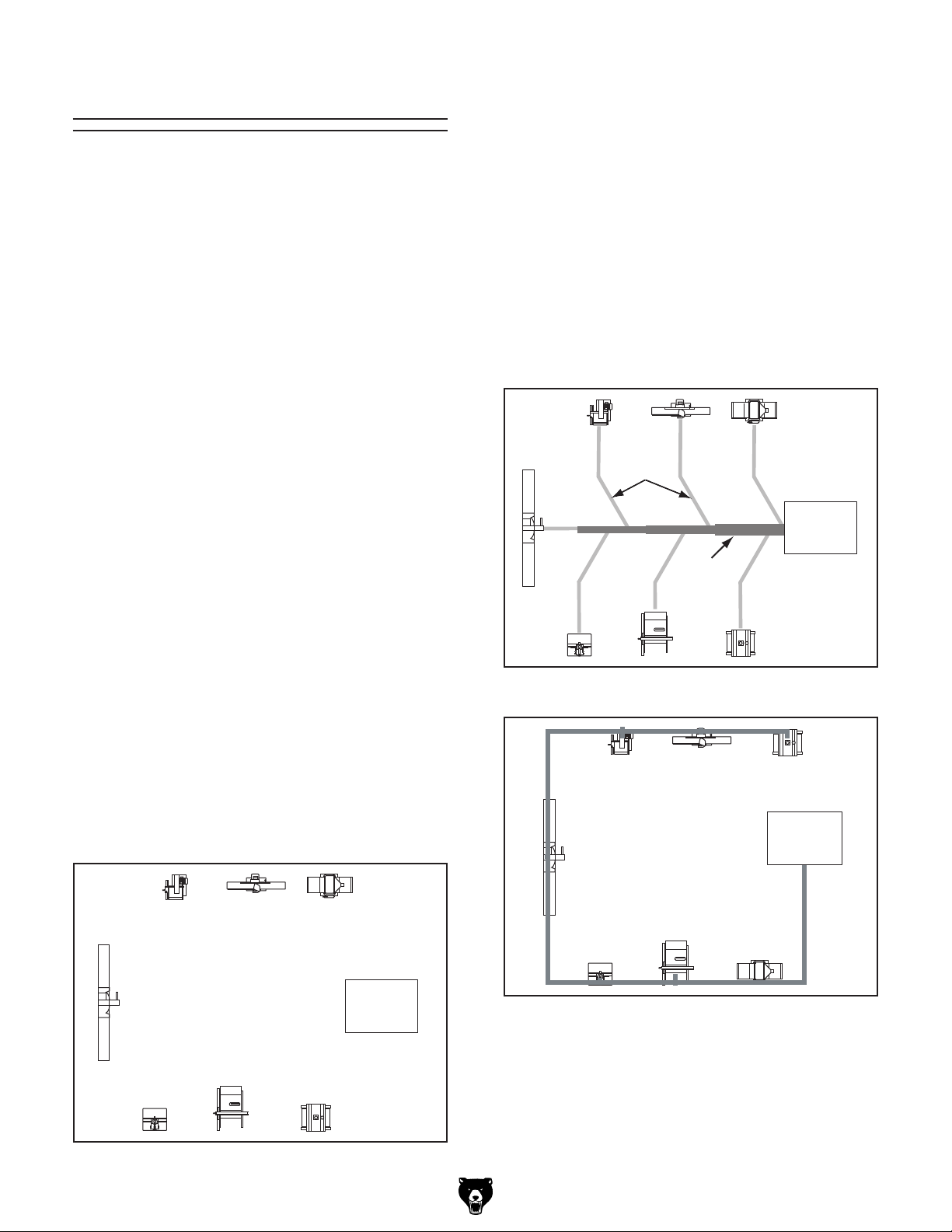
1.
should be placed nearest to the dust collector
2. Ideally, you should design the duct system to
have the shortest possible main line and sec-
below
layouts.
Decide Who Will Design
Sketch a Basic Duct Layout
Machines that produce the most saw dust
(i.e. planers and sanders).
ondary branch ducts. See the figures
for ideas of efficient versus inefficient duct
Sketch Your Shop Layout
Workshop Planner
http://www.grizzly.com/workshopplanner.
Workshop Planner will allow you to quickly
Note:
the figure below, includ-
Branch
Line
Ducts
Main
Line Duct
Figure 44. Efficient duct layout.
BAD
GOOD
Collector
Dust
Collector
Dust
Figure 43. Basic sketch of shop layout.
G0548ZP, G1028Z2, G1029Z2-Z2P (Mfg. 12/12+)
Dust
Collector
Figure 45. Inefficient duct layout.
-27-
Page 30

If the machine does not have a built-in dust port,
use
to determine which size of
dust port to install.
Table Saw
PlanerShaper
Write the required CFM for each machine on your
sketch, as shown in the figure below.
3. Directional changes should be kept to a mini-
mum. The more directional change fittings
4.
5.
6.
and less costly it will be.
Since each machine produces a different amount
of sawdust, the requirements for the minimum
amount of CFM to move that sawdust is unique
to the machine (for example, a planer produces
more sawdust than a table saw). Knowing this
required CFM is important to gauging which size
of duct to use.
Refer to the
below for a close estimation of
the airflow each machine requires. Keep in mind
that machines that generate the most sawdust
should be placed closest to the dust collector.
If the machine has multiple dust ports, the total
CFM required is the sum of all ports.
you use directly increases the overall resistance to airflow.
the following table
Gradual directional changes are more effi-
cient than sudden directional changes (i.e.
use the largest corner radius possible when
changing hose or pipe direction).
Each individual branch line should have a
blast gate immediately after the branch to
control suction from one machine to another.
The simpler the system, the more efficient
Determine Required CFMs
figure
Machine Average Dust Port Size
Table Saw ......................................................4"
Miter/Radial-Arm Saw ....................................2"
Jointer (6" and smaller) .................................4"
Jointer (8"-12") ...............................................5"
Thickness Planer (13" and smaller) ............... 4"
Thickness Planer (14"-20") ............................6"
Shaper ...........................................................4"
Router (mounted to table) ..............................2"
Bandsaw ........................................................ 4"
Lathe .............................................................. 4"
Disc Sander (12" and smaller) .......................2"
Disc Sander (13-18") ......................................4"
Belt Sander (6" and smaller) .........................2"
Belt Sander (7"-9") ........................................3"
Edge Sander (6" x 80" and smaller) .............. 4"
Edge Sander (6" x 80" and larger) ................5"
Drum Sander (24" and smaller) ...............2 x 4"
Drum Sander (24" and larger) .................4 x 4"
Widebelt Sander (18" and smaller) ................ 5"
Widebelt Sander (24"-37" single head) ...2 x 6"
Widebelt Sander (24"-51" double head) .. 5 x 4"
Figure 47. Dust port size and quantity per
average machine.
Machine
Dust Port Size
2" 98
2.5" 150
3" 220
4" 395
Figure 46. Approximate required airflow for
-28-
5" 614
6" 884
7" 1203
8" 1570
9" 1990
10" 2456
machines, based on dust port size.
Approximate
Required CFM
395
Sander
790395
Dust
Collector
614
Planer/
Moulder
Miter
Saw
98
220
Figure 48. CFM requirements labeled for each
G0548ZP, G1028Z2, G1029Z2-Z2P (Mfg. 12/12+)
Jointer
395
machine.
Page 31

Determining Main Line Duct Size
The general rule of thumb for a main line duct is
that the velocity of the airflow must not fall below
3500 FPM.
For small/medium sized shops, using the inlet size
of the dust collector as the main line duct size
will usually keep the air velocity above 3500 FPM
and, depending on your system, will allow you to
keep multiple branches open at one time.
Mark your drawing, as shown in the
below,
but using the inlet size for your dust collector as
the main line.
The general rule of thumb for a branch line duct is
that the velocity of the airflow must not fall below
4000 FPM.
For small/medium sized shops, using the dust
port size from the machine as the branch line duct
size will achieve the correct velocity in most applications. However, if the dust port on the machine
is smaller than 4", make the branch line 4" and
neck the line down right before the dust port.
Note: Systems with powerful dust collectors work
better if multiple blast gates are left open. This
also allows you to run two machines at once.
Experiment with different combinations of blast
gates open/closed to find the best results for your
system.
Write your determined branch line sizes on your
drawing, as shown in the following figure.
If two machines will connect to the same branch
line and both will operate at the same time, then
add the required CFM for each machine together
and
to determine the correct branch size
If both machines will never run at the same time,
reference the machine with the biggest dust port
in the table
Y-branch to open/close the line to each machine.
Planer/
Moulder
4"
Jointer Sander
395
395
4" 6"
790
figure
Jointer Sander
395
395
Table Saw
790395
Collector
614
PlanerShaper
Miter
Saw
98
Planer/
Moulder
5" 6" 7"
220
Figure 49. Main line size labeled on sketch.
Determining Branch Line Duct Size
Dust
Miter
Saw
98
5" 6" 7"
4"
4" 4" 5"
220
Table Saw
395
PlanerShaper
Dust
Collector
614
Figure 50. Branch line duct sizes labeled.
find the closest total CFM in the table below
.
below and add blast gates after the
Total CFM Branch Line Size
400 4"
500 4"
600 5"
700 5"
800 6"
900 6"
1000 6"
Figure 51. Sizing chart for multiple machines on
the same branch line.
G0548ZP, G1028Z2, G1029Z2-Z2P (Mfg. 12/12+)
-29-
Page 32

In most small/medium shops it is only necessary
to calculate the line with the longest duct length or
the most fittings (operating under the assumption
that if the line with the highest resistance works,
the others will be fine).
To calculate the static pressure of any given
line in the system, follow these steps:
1.
the
2.
pressure loss given in the previous table.
Adding duct work, elbows, branches and any
other components to a duct line increases airflow
resistance (static pressure loss). This resistance
can be minimized by using rigid (smooth) pipe and
gradual curves, as opposed to flexible pipe and
90˚ elbows.
To help you think about this resistance, imagine
riding a bicycle in a tunnel that is an exact replica
of your duct work. If the inside of the tunnel is very
bumpy (flexible pipe) and has a lot of sharp turns
(90˚ elbows), it will take a lot more effort to travel
from one end to the other.
The purpose of calculating the resistance is to
determine if it is low enough from the machine to
the dust collector to meet the given CFM requirement for the machine. Use the
to
calculate the resistance of duct work.
Planning Drop Downs
Plan the drop downs for each machine, using
blast gates wherever possible to control airflow.
Elbow
Rigid Pipe
(Main Line)
Y Branch
Clamp
Flex Pipe
To Planer
Figure 52. Drop down setup.
Rigid Pipe
Blast Gate
Calculating Duct Resistance
Duct
Dia.
2" 0.091 0.122 0.35 0.453
2.5" 0.08 0.107 0.306 0.397
3" 0.071 0.094 0.271 0.352
4" 0.057 0.075 0.215 0.28
5" 0.046 0.059 0.172 0.225
6" 0.037 0.047 0.136 0.18
7" 0.029 0.036 0.106 0.141
8" 0.023 0.027 0.08 0.108
9" 0.017 0.019 0.057 0.079
Fitting
Dia.
Approximate
Static Pressure
Loss Per Foot of
Rigid Pipe
Main
Lines
at 3500
FPM
90˚
Elbow
Branch
Lines
at 4000
FPM
45˚
Elbow
Approximate
Static Pressure
Loss Per Foot
of Flex Pipe
Main
Lines
at 3500
FPM
45˚
Wye(Y)
Branch
Lines
at 4000
FPM
90˚
Wye(Y)
-30-
following tables
3" 0.47 0.235 0.282 0.188
4" 0.45 0.225 0.375 0.225
5" 0.531 0.266 0.354 0.236
6" 0.564 0.282 0.329 0.235
7" 0.468 0.234 0.324 0.216
8" 0.405 0.203 0.297 0.189
Figure 53. Static pressure loss charts.
Make a list of each size duct in the line,
including the length, and multiply those numbers by the static pressure value given in
previous table.
List each type of elbow or branch and multiply
the quantity (if more than one) by the static
G0548ZP, G1028Z2, G1029Z2-Z2P (Mfg. 12/12+)
Page 33

Additional Factors Static Pressure
4. Total your list as shown in the example below
Always account for a seasoned filter,
so you don't end up with a system that only
works right when the filter is clean.
Note: When calculating static pressure loss
to determine if multiple lines can be left open
at the same time, only include the main line
5. Compare the total static pressure loss for
that line to the maximum static pressure loss
(located toward the front of this manual).
—If the CFM for your static pressure loss
ve just designed
to start
buying the components necessary to make
—If the CFM for your static pressure loss is
below the requirement of the machine, then
that line will not effectively collect the dust.
loss. Some of the ways to do this include 1)
installing larger duct, 2) reducing amount of
dust port size, 4) moving machine closer to
dust collector to eliminate duct length, and
with 45˚ elbows.
After the system is designed, create a materials
list of all the items you will need to build your dust
collection system. This will make it easy when it
comes time to purchase the materials.
Below is an example of some items that might be
needed. Refer to
for dust collection
components available through g rizzly.c om .
3. Add the additional factors from the following-
table to your list.
found on the data sheet for your machine
Seasoned (well used)
1"
Dust Collection Filter
Entry Loss at Large
2"
Machine Hood
Figure 54. Additional factors affecting static
pressure.
to come up with your overall static pressure
loss number for that line.
Note:
Main Line
6" Rigid Pipe (0.037) at 20' ................ 0.740
Branch Line
4" Rigid Pipe (0.075) at 10' ................ 0.750
4" Flex Pipe (0.28) at 5' ........................ 1.400
is above the requirement of the machine,
then the line will most likely be successful. Congratulations! You’
your own dust system. Compile a list of
materials and refer to Accessories
You must then modify some of the factors
in that line to reduce the static pressure
flexible duct used, 3) increasing machine
5) reducing 90˚ elbows or replacing them
Compile Materials List
Elbows/Branches
6" 45˚ Y-Branch ................................ 0.329
4" 45˚ Elbow ........................................ 0.225
Additional Factors
Seasoned Filter ................................ 1.000
Total Static Pressure Loss ................ 4.444
Figure 55. Totaling static pressure numbers.
G0548ZP, G1028Z2, G1029Z2-Z2P (Mfg. 12/12+)
Accessories
Description Model Quantity
6" Rigid Pipe at 20' G7364 4
4" Rigid Pipe at 10' G6162 2
4" Flex Hose at 5' H7215 6
6" 45° Y-Branch G7353 6
4" 45° Elbow G6167 6
Figure 56. Example materials list.
-31-
Page 34

System Grounding
Since plastic hose is abundant, relatively inexpensive, easily assembled and air tight, it is a
very popular material for conveying dust from
woodworking machines to the dust collector. We
recommend using flexible hose (flex-hose) to
connect the woodworking machine to the dust
collector. However, plastic flex-hose and plastic
duct are an insulator, and dust particles moving
against the walls of the plastic duct create a static
electrical build up. This charge will build until it
discharges to a ground. If a grounding medium
is not available to prevent static electrical build
up, the electrical charge will arc to the nearest
grounded source. This electrical discharge may
cause an explosion and subsequent fire inside
the system.
To protect against static electrical build up inside
a non-conducting duct, a bare copper wire should
be placed inside the duct along its length and
grounded to the dust collector. You must also
confirm that the dust collector is continuously
grounded through the electrical circuit to the electric service panel.
If you connect the dust collector to more than one
machine by way of a non-conducting branching
duct system and blast gates, the system must still
be grounded as mentioned above. We recommend inserting a continuous bare copper ground
wire inside the entire duct system and attaching
the wire to each grounded woodworking machine
Be sure that you extend the bare copper wire
down all branches of the system. Do not forget
to connect the wires to each other with wire nuts
when two branches meet at a “Y” or “T” connection.
Ensure that the entire system is grounded. If using
plastic blast gates to direct air flow, the grounding wire must be jumped (see the figure
below)
around the blast gate without interruption to the
grounding system.
We also recommend wrapping the outside of all
outside of the system against static electrical build
in your electric service panel.
Always guard against
by grounding all dust
Plastic Blast
Gate
Metal Duct
Copper
Ground Wire
-32-
static electrical build up
collection lines.
Figure 57. Ground jumper wire when using
plastic blast gates and metal duct.
plastic ducts with bare copper wire to ground the
up. Wire connections at Y’s and T’s should be
made with wire nuts.
Attach the bare ground wire to each stationary
woodworking machine and attach to the dust
collector frame with a ground screw as shown
in the figure below. Ensure that each machine is
continuously grounded to the grounding terminal
External
Ground Wire
Internal
Ground Wire
Flex-Hose
Figure 58. Flex-hose grounded to machine.
G0548ZP, G1028Z2, G1029Z2-Z2P (Mfg. 12/12+)
Ground
Screw
Page 35

SECTION 5: OPERATIONS
To reduce your risk of
serious injury, read this
entire manual BEFORE
To reduce risk of eye injury from flying
using machine.
chips or lung damage from breathing dust,
always wear safety glasses and a respirator
when operating this machine.
General
Operating a dust collector is simple and straightforward. Turn the dust collector ON, then turn
the dust producing machine ON. When you are
finished with the machine operation, turn the
machine OFF, then turn the dust collector OFF.
Blast gates can be used at the start of each branch
line to control the air flow from the woodworking
machine to the dust collector. If a machine is not
being used, keep the blast gate closed to maintain
higher levels of efficiency throughout the system.
Machine Storage
If you are not experienced with this type
of machine, WE STRONGLY RECOMMEND
that you seek additional training outside of
this manual. Read books/magazines or get
formal training before beginning any projects. Regardless of the content in this section, Grizzly Industrial will not be held liable
for accidents caused by lack of training.
Do NOT put hands or
small objects near inlet
openings during operation. Objects sucked
into the inlet will meet
with the impeller blade.
Failure to heed this
warning could result in
property damage or personal injury.
When the dust collector is not in use, unplug the
power cord from the power source. Place the
cord away from potential damage sources, such
as high traffic areas, sharp objects, heat sources,
harsh chemicals, water, damp areas, etc.
G0548ZP, G1028Z2, G1029Z2-Z2P (Mfg. 12/12+)
-33-
Page 36

SECTION 6: ACCESSORIES
Installing unapproved accessories may
order online at www.grizzly.com or call 1-800-523-4777
cause machine to malfunction, resulting in
serious personal injury or machine damage.
To reduce this risk, only install accessories
recommended for this machine by Grizzly.
NOTICE
Refer to our website or latest catalog for
additional recommended accessories.
T20543— 41" x 31" Flat 19.75" Dia. Plastic
Bottom Bag
Replacement plastic lower bag for G0548ZP,
G1029Z2/G1029Z2P, and G1028Z2.
G5556—2.5 Micron Dust Bag
Replacement top bag for Grizzly G1028Z2
and G1029Z2/G1029Z2P dust collectors.
These offer the largest airflow, least differential pressure and best overall efficiency
available. Micro-porous to shed dust and dirt,
so bags empty quickly and completely. 2.5
Microns! Captures the finest, most hazardous dust.
H5783—Extra 1 Micron Canister
Replacement canister for Grizzly G0548ZP,
G0562Z/G0562ZP, G1028Z/Z2, G1029Z/Z2/
Z2P, and G1030Z/Z2/Z2P Dust Collectors.
Figure 59. Replacement canister.
Figure 60. G5556 2.5 Micron Dust Bag.
G1536—Black Flexible Hose 4" x 10'
G2974—Wire Hose Clamp 4"
G1843—Plastic Blast Gate 4"
G4679—Anti-Static Grounding Kit
We've hand picked a selection of commonly used
dust collection components for machines with 4"
dust ports.
G2974
G1843
G1536
G4679
Figure 61. Dust collection accessories.
-34-
G0548ZP, G1028Z2, G1029Z2-Z2P (Mfg. 12/12+)
Page 37

H5293—4" Metal Duct Starter Kit
H5295—5" Metal Duct Starter Kit
H5297—6" Metal Duct Starter Kit
Save over 20% with this great starter kit.
Includes: (2) machine adapters, (10) pipe
clamps, (3) 5' straight pipes, (1) branch, (3)
pipe hangers, (1) end cap, (3) adjustable
nipples, (1) 90˚ elbow, and (1) 60˚ elbow.
H7215—4" x 5' Rigid Metal Flex Hose
H7216—5" x 5' Rigid Metal Flex Hose
H7217—6" x 5' Rigid Metal Flex Hose
This flex hose provides just enough flexibility
to make difficult connections while still keeping the inside wall as smooth as possible to
minimize static pressure loss.
Figure 65. Rigid Metal Flex Hose.
Metal Elbows
These industrial metal elbows are available
from 4"–8" with 90˚, 60˚, 45˚, or 30˚ curves.
Figure 62. Metal Duct Starter Kit.
G6163—4" Clamp
G7343—5" Clamp
G7361—6" Clamp
These clamps feature lever latches and foam
seals, and secure around the rolled ends of fittings and pipe.
Figure 63. Dust collection pipe clamps.
G6162—4" x 5' Straight Metal Pipe
G7346—5" x 5' Straight Metal Pipe
G7364—6" x 5' Straight Metal Pipe
These laser welded straight pipes ensure
a super smooth internal seam. Ends easily
clamp together for a sealed fit without screws
or silicone.
30°
90°
45°
90° Long Radius
60°
Figure 66. Metal elbow examples.
Reducers & Adapters
We carry a multitude of reducers and elbows
to cover most applications from 4" through 9".
Figure 67. Metal Reducers & Adapters.
Metal Branches
We carry a selection of different branches.
Figure 64. Straight Metal Pipe.
G0548ZP, G1028Z2, G1029Z2-Z2P (Mfg. 12/12+)
Figure 68. Metal Branches.
-35-
Page 38

SECTION 7: MAINTENANCE
Always disconnect power
to the machine before
performing maintenance.
Failure to do this may
result in serious personal injury.
Schedule
For optimum performance from your machine,
follow this maintenance schedule and refer to any
specific instructions given in this section.
Daily Check:
• Loose mounting bolts.
• Worn switch.
• Worn or damaged wires.
• Clean canister filter (G0548ZP only).
• Check collection bag.
• Any other unsafe condition.
Always wear a respirator
and safety glasses when
emptying the dust collection
bags on the dust collector.
Sawdust may cause allergic
reactions or respiratory
problems.
Cleaning Bags
Always empty the collection bags on a regular
basis. Emptying the collection bags allows the
machine to operate at a much higher level of
efficiency.
Always wear the appropriate respirator or dust
mask and safety glasses when emptying the collection bags. Small dust particles can escape the
bags during emptying, causing them to become
airborne and easily inhaled. This microscopic airborne dust is extremely unhealthy to breathe and
can cause serious health problems.
Lubrication
Since all bearings are shielded and permanently
lubricated, simply leave them alone until they
need to be replaced. Do not lubricate them.
While this dust collector excels at collecting the
majority of wood dust produced by your machines,
it is not an air filter; therefore, we strongly rec-
ommend the supplemental aid of a shop air filter
such as the Grizzly G0572 or G9956. Air filters
are designed to collect the smaller dust particles
that dust collector bags cannot trap.
-36-
G0548ZP, G1028Z2, G1029Z2-Z2P (Mfg. 12/12+)
Page 39

Replacing Bags
Replacement plastic lower collection bags are
available through Grizzly as Model T20543.
Replacement top dust bags are available for the
Model G1028Z2/G1029Z2/Z2P as Model G5556.
To replace the collection bag:
1. DISCONNECT MACHINE FROM POWER!
2. Make sure you are wearing safety glasses
and a respirator.
3. Release the belt clamp securing the collec-
tion bag, then unhook the bag from the collector.
4. Securely close the top of the bag and safely
dispose of it according to local and federal
standards.
Cleaning Canister
Filter
To clean the canister filter on the Model G0548ZP,
move the canister cleaning handle back-and-forth
to free the trapped dust particles from the filter
pleats (see Figure 69). The particles will fall into
the collection bag.
The replacement canister for the G0548ZP is the
Model H5783, which can also be installed on the
G1028Z2/G1029Z2/Z2P, if you would ever like to
upgrade.
5. Install a new collection bag.
Figure 69. Canister cleaning handle directions.
NOTICE
The use of compressed air or liquids to
clean the canister filter will damage the
filtration pleats of the filter. Use ONLY the
cleaning handle or, if necessary, a soft
brush to clean the inside of the canister
filter.
G0548ZP, G1028Z2, G1029Z2-Z2P (Mfg. 12/12+)
-37-
Page 40

SECTION 8: SERVICE
Review the troubleshooting and procedures in this section if a problem develops with your machine. If you
need replacement parts or additional help with a procedure, call our Technical Support at (570) 546-9663.
Note: Please gather the serial number and manufacture date of your machine before calling.
To reduce the risk of serious personal injury or damage to the machine, any repairs not covered in this
manual should only be performed by or with the assistance of qualified service personnel.
Troubleshooting
Motor & Electrical
Symptom Possible Cause Possible Solution
Machine does
not start or a
breaker trips.
Machine has
vibration or
noisy operation.
1. Switch disabling key removed.
2. Power supply switched OFF or is at fault.
3. Wall fuse/circuit breaker is blown/tripped.
4. Wiring is open/has high resistance.
5. Motor ON/OFF switch is at fault.
6. Motor is at fault.
1. Motor, motor mount, or other mounting
component is loose or broken.
2. Machine is incorrectly "mounted" or
sits unevenly on its casters.
3. Motor fan is rubbing on fan cover.
4. Impeller is loose or damaged and
unbalanced.
5. Motor bearings are at fault.
1. Install switch disabling key.
2. Ensure power supply is switched ON; ensure
power supply has the correct voltage.
3. Ensure circuit size is suitable for this
machine; replace weak breaker.
4. Check for broken wires or disconnected/
corroded connections, and repair/replace as
necessary.
5. Replace faulty ON/OFF switch.
6. Test/repair/replace.
1. Retighten. Use thread locking fluid if necessary.
Replace stripped fasteners or damaged
components if necessary.
2. Tighten/replace anchor studs in floor if mounted;
chock machine casters if mobile.
3. Replace dented fan cover; replace loose/
damaged fan.
4. Disconnect dust collector from power, and
inspect the impeller for dents, bends, loose
fins. Replace the motor and impeller as a set if
the motor shaft and the impeller hub are damaged.
5. Test by rotating shaft; rotational grinding/loose
shaft requires bearing replacement.
-38-
G0548ZP, G1028Z2, G1029Z2-Z2P (Mfg. 12/12+)
Page 41

Dust Collector Operation
Symptom Possible Cause Possible Solution
Dust collector does
not adequately
collect dust
or chips; poor
performance.
Sawdust being
blown into the
air from the dust
collector.
1. Dust collection bags are full.
2. Canister is dirty.
3. Restriction in duct line.
4. Dust collector is too far away, or there
are too many sharp bends in the ducting.
5. Lumber is wet and dust not flowing
through ducting smoothly.
6. Leaks in ducting or too many open ports.
7. Not enough open branch lines, causing
a velocity drop in the main line.
8. Ducting or machine dust ports are
incorrectly sized.
9. The machine dust collection design is
inadequate.
10. The dust collector is too small for
the dust collection system, or ducting
layout design inadequate.
1. Duct clamps or dust collection bags
are not properly clamped and secured.
1. Empty collection bags.
2. Clean canister.
3. Remove restriction in the duct line. A plumbing
snake may be necessary.
4. Relocate the dust collector closer to the point
of suction, and rework ducting without sharp
bends. Refer to System Design, beginning on
Page 27.
5. Process lumber with less than 20% moisture
content.
6. Rework the ducting to eliminate all leaks. Close
dust ports for lines not being used.
7. Open 1 or 2 more blast gates to different
branch lines to allow the velocity in the main
line to increase.
8. Re-install correctly sized ducts and fittings.
Refer to System Design beginning on Page
27 for more solutions.
9. Use a dust collection nozzle on a stand.
10. Install a larger dust collector to power your dust
collection system.
1. Re-secure ducts and dust collection bag, making
sure duct and bag clamps are tight and completely
over the ducts and bags.
G0548ZP, G1028Z2, G1029Z2-Z2P (Mfg. 12/12+)
-39-
Page 42

These pages are current at the time of printing. However, in the spirit of improvement, we may make changes to the electrical systems of future machines. Compare the manufacture date of your machine to the one
number and manufacture date of your
machine before calling. This information can be found on the main machine label.
machine
SECTION 9: WIRING
stated in this manual, and study this section carefully.
If there are differences between your machine and what is shown in this section, call Technical Support at
(570) 546-9663 for assistance BEFORE making any changes to the wiring on your machine. An updated
wiring diagram may be available. Note: Please gather the serial
Wiring Safety Instructions
SHOCK HAZARD. Working on wiring that is connected to a power source is extremely dangerous.
Touching electrified parts will result in personal
injury including but not limited to severe burns,
electrocution, or death. Disconnect the power
from the machine before servicing electrical components!
MODIFICATIONS. Modifying the wiring beyond
what is shown in the diagram may lead to unpredictable results, including serious injury or fire.
This includes the installation of unapproved aftermarket parts.
WIRE CONNECTIONS. All connections must
be tight to prevent wires from loosening during
machine operation. Double-check all wires disconnected or connected during any wiring task to
ensure tight connections.
CIRCUIT REQUIREMENTS. You MUST follow
the requirements at the beginning of this manual when connecting your machine to a power
source.
WIRE/COMPONENT DAMAGE. Damaged wires
or components increase the risk of serious personal injury, fire, or machine damage. If you notice
that any wires or components are damaged while
performing a wiring task, replace those wires or
components.
MOTOR WIRING. The motor wiring shown in
these diagrams is current at the time of printing
but may not match your machine. If you find this
to be the case, use the wiring diagram inside the
motor junction box.
CAPACITORS/INVERTERS. Some capacitors
and power inverters store an electrical charge for
up to 10 minutes after being disconnected from
the power source. To reduce the risk of being
shocked, wait at least this long before working on
capacitors.
EXPERIENCING DIFFICULTIES. If you are experiencing difficulties understanding the information
included in this section, contact our Technical
Support at (570) 546-9663.
The photos and diagrams
included in this section are
best viewed in color. You
can view these pages in
color at www.grizzly.com.
-40-
G0548ZP, G1028Z2, G1029Z2-Z2P (Mfg. 12/12+)
Page 43
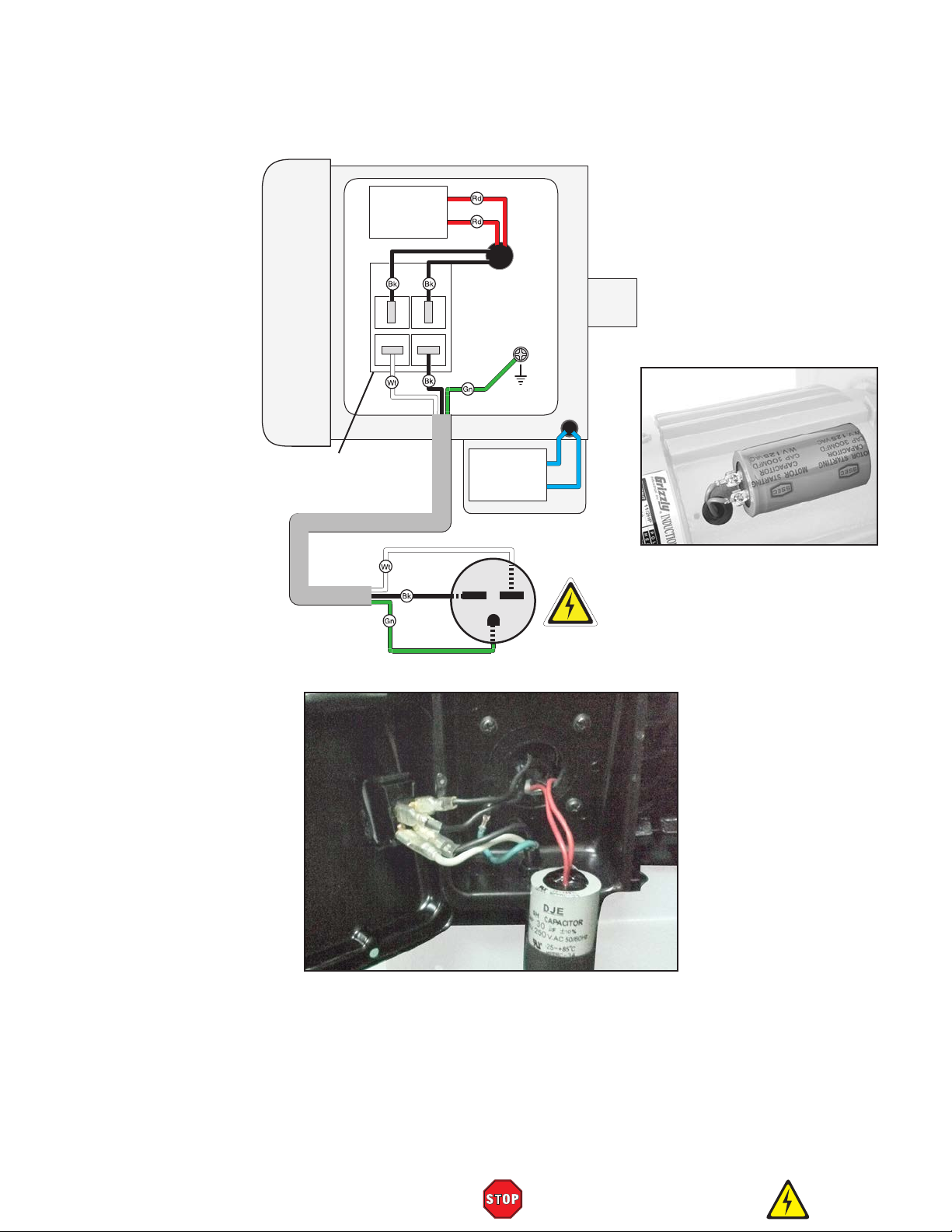
240 VOLT
Ground
G0548ZP Wiring Diagram
Run
Capacitor
30MFD
250VAC
MOTOR
Start
PADDLE SWITCH
(viewed from behind)
Capacitor
300MFD
125VAC
Hot
Hot
Ground
G
(As Recommended)
240V
6-15 Plug
Figure 71. G0548ZP junction box, switch and
run capacitor.
Figure 70. G0548ZP start
capacitor.
G0548ZP, G1028Z2, G1029Z2-Z2P (Mfg. 12/12+)
READ ELECTRICAL SAFETY
ON PAGE 40!
-41-
Page 44
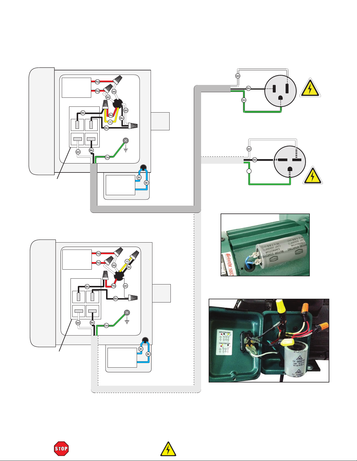
G1028Z2 Wiring Diagram
(viewed from behind)
Ground
Ground
120 VOLT (PREWIRED)
Run
Capacitor
45MFD
250VAC
PADDLE SWITCH
240 VOLT (REWIRED)
Start
Capacitor
300MFD
125VAC
MOTOR
Rewired 240V
Neutral
Gn
Hot
Ground
Hot
Hot
Ground
6-15 Plug
(As Recommended)
120V
5-15 Plug
(Prewired)
240V
G
PADDLE SWITCH
Run
Capacitor
45MFD
250VAC
Start
Capacitor
300MFD
125VAC
MOTOR
Figure 72. G1028Z2 start
capacitor.
Rewired 240V
Figure 73. G1028Z2 junction box, switch
and run capacitor at 120V.
-42-
READ ELECTRICAL SAFETY
ON PAGE 40!
G0548ZP, G1028Z2, G1029Z2-Z2P (Mfg. 12/12+)
Page 45

Ground
G1029Z2/G1029Z2P Wiring Diagram
240 VOLT
MOTOR
PADDLE SWITCH
(viewed from behind)
Ground
Hot
Hot
Start
Capacitor
300MFD
125VAC
240V
G
6-15 Plug
(As Recommended)
Figure 74. G1029Z2 start
capacitor.
Figure 75. G1029Z2 junction box and switch.
G0548ZP, G1028Z2, G1029Z2-Z2P (Mfg. 12/12+)
READ ELECTRICAL SAFETY
ON PAGE 40!
-43-
Page 46
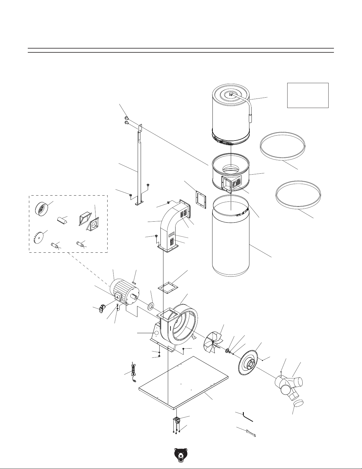
17-2
17-1
17-4
17-3
SECTION 10: PARTS
G0548ZP Main Breakdown
14
23
28
2
17-5
17-6
19
2
2
37
36
44
39
35V2
35
34
24
27A
H5783 Parts
Breakdown
on Page 46
41
42
21
21V2
40
15
17
17V2
12
31
31V2
43
30
25
12
18
28
11
2
22
10
10V2
45
9
6
7V2
2
13
5
4
1
26
32
29
29-1
-44-
G0548ZP, G1028Z2, G1029Z2-Z2P (Mfg. 12/12+)
Page 47

G0548ZP Main Parts List
REF PART # DESCRIPTION REF PART # DESCRIPTION
1 P1028Z2001 CASTERS 22 T20543 COLLECTION BAG
2 PFB01 FLANGE BOLT 5/16-18 X 1/2 23 P0548Z023 COLLECTOR SUPPORT
4 P1028Z2004 BASE PLATE 24 P0548ZP024 COLLECTOR
5 PS06 PHLP HD SCR 10-24 X 3/8 25 P0548Z025 SPACER
6 P0548ZP006 6" INLET COVER 26 PAW05M WRENCH HEX 5MM
7V2 P1028Z2007V2 CAP SCREW M6-1 X 30 LH PRE-COATED 27A H5783 COMPLETE CANISTER ASSY
9 P0548009 IMPELLER WASHER 7 X 40 X 4 28 P1028Z2028 RUBBER GASKET
10 P1029Z2010V2 IMPELLER 12-3/4" ALUMINUM V2.09.11 29 P0548ZP029 INLET
11 P0548ZP011 COLLECTOR BODY 29-1 P0548Z029-1 INLET CAP
12 PW07 FLAT WASHER 5/16 30 PK28M KEY 7 X 7 X 29
13 PS06 PHLP HD SCR 10-24 X 3/8 31 P1029Z2013V2 PWR CORD 14G 3W 6' 6-15 V2.09.11
14 PFB01 FLANGE BOLT 5/16-18 X 1/2 32 PWR1012 WRENCH 10 X 12MM OPEN-END
15 PB03 HEX BOLT 5/16-18 X 1 34 P1028Z2031 BELT CLAMP
17 P0548ZP017 MOTOR 2HP 220V 1PH 35 P0548ZP035 MACHINE ID LABEL
17-1 P0548ZP017-1 MOTOR FAN COVER 36 PLABEL-12 READ MANUAL 2W X 3.3H
17-2 P0548Z017V2-2 MOTOR FAN 37 PLABEL-57 EYE/LUNG LABEL
17-3 P0548ZP017-3 CAPACITOR COVER 39 PLABEL-59 NO HAND IN INLET LABEL
17-4 PC300B S CAPACITOR 300M 125V 1-3/4 X 3-3/8 40 PLABEL-14 ELECTRICITY LABEL 1.4W X 1.2H
17-5 P0548ZP017-5 MOTOR WIRING JUNCTION BOX 41 P0548Z041 FOAM STRIP 5 X 42MM
17-6 PC030C R CAPACITOR 30M 250V 1-3/8 X 2-3/8 42 P0548Z042 FOAM STRIP 4 X 20MM
18 PN02 HEX NUT 5/16"-18 43 PPAINT-24 POLAR BEAR PAINT
19 P0548ZP019 OUTLET CONNECTOR 44 PLABEL-81 POLAR BEAR LOGO 1 X 3-3/4
21 P1030Z2015V2 PADDLE SWITCH V2.09.11 45 PLW03M LOCK WASHER 6MM
G0548ZP, G1028Z2, G1029Z2-Z2P (Mfg. 12/12+)
-45-
Page 48

H5783 breakdown
H5783 Canister Filter Assembly
8V2
1
20
21
22
23
24
2
3
5
7
6
4
16
15
14
12
17
18
19
REF PART # DESCRIPTION REF PART # DESCRIPTION
1 PH5783001 CLEANING HANDLE 15 PH5783015 SUPPORT TAB
2 PB83M HEX BOLT M6-1 X 16 16 PN06M HEX NUT M5-.8
3 PH5783003 CANISTER FILTER 17 PW06 FLAT WASHER 1/4
4 PH5783004 HEX SPINDLE 18 PS68M PHLP HD SCR M6-1 X 10
5 PH5783005 THRUST BEARING 12 X 14 X 6 19 PH5783019 SPONGE GASKET 10 X 15MM
6 PH5783006 BEARING PLATE 20 PH5783020 HANDLE SLEEVE
7 PS09M PHLP HD SCR M5-.8 X 10 21 PH5783021 HANDLE CAP
8V2 PH5783008V2 PLASTIC FLAP BOARD V2.09.11 22 PH5783022 QUICK RELEASE CLAMP
9 PS68M PHLP HD SCR M6-1 X 10 23 PH5783023 FOAM STRIP 20MM X 156CM
12 PS20M PHLP HD SCR M5-.8 X 15 24 PH5783024 FOAM STRIP 42MM X 156CM
14 PH5783014 BOTTOM PLATE 26 PW03M FLAT WASHER 6MM
26
9
5
6
7
-46-
G0548ZP, G1028Z2, G1029Z2-Z2P (Mfg. 12/12+)
Page 49

G1028Z2/G1029Z2 Main Breakdown
26
17V2-1
17V2-2
102
101
17V2-3
17V2-4
103
17V2-5
104V2
2
23
2
17V2-6
(G1028Z2)
17V2
16V2
105
15
12
106
27
31
30
24
20
21
20
2
3
25
12
14
19
28
11
2
10V2
22
9
35
7V2
5
2
23
2
6
18
29
13V2
4
1
2
33
32
29-1
Safety labels warn about machine hazards and ways to prevent injury. The owner of this machine
MUST maintain the original location and readability of the labels on the machine. If any label is
removed or becomes unreadable, REPLACE that label before using the machine again. Contact
Grizzly at (800) 523-4777 or www.grizzly.com to order new labels.
G0548ZP, G1028Z2, G1029Z2-Z2P (Mfg. 12/12+)
-47-
Page 50

G1028Z2 Main Parts List
REF PART # DESCRIPTION REF PART # DESCRIPTION
1 P1028Z2001 CASTER 19 P1028Z2019 OUTLET
2 PFB01 FLANGE BOLT 5/16-18 X 1/2 20 P1028Z2020 HOSE CLAMP 5"
3 PK32M KEY 6 X 6 X 28 21 P1028Z2021 HOSE 5"
4 P1028Z2004 BASE PLATE 22 T20543 LOWER PLASTIC BAG
5 PS06 PHLP HD SCR 10-24 X 3/8 23 P1028Z2023 COLLECTOR SUPPORT
6 P1028Z2006 INLET COVER 6" 24 P1028Z2024 COLLECTOR
7V2 P1028Z2007V2 CAP SCREW M6-1 X 30 LH PRE-COATED 25 P1028Z2025 SPACER
9 P1028Z2009 IMPELLER WASHER 26 P1028Z2026 UPPER BAG SUPPORT
10V2 P1028Z2010V2 IMPELLER 12-3/4"D X 85MM H X 3/4" ALUM 27 G5556 2.5 MICRON FILTER BAG
V2.09.11 28 P1028Z2028 GASKET
11 P1028Z2011 COLLECTOR BODY 29 P1028Z2029 Y-INLET 6 X 4 X 4"
12 PW07 FLAT WASHER 5/16 29-1 P1028Z2029-1 INLET CAP 4"
13V2 P1028Z2013V2 POWER CORD 14G 3W 6' 5-15 V2.09.11 30 P1028Z2030 FOAM STRIP 5 X 20MM
14 PN02 HEX NUT 5/16-18 31 P1028Z2031 BELT CLAMP
15 PB03 HEX BOLT 5/16-18 X 1 32 PWR1012 WRENCH 10 X 12MM OPEN-END
16V2 P1028Z2016V2 PADDLE SWITCH V2.09.11 33 PAW05M WRENCH HEX 5MM
17V2 P1028Z2017V2 MOTOR 1-1/2HP 120V/240V 1PH V2.09.11 35 PLW03M LOCK WASHER 6MM
17V2-1 P1028Z2017V2-1 MOTOR FAN COVER 101 PLABEL-14 ELECTRICITY LABEL
17V2-2 P1028Z2017V2-2 MOTOR FAN 102 PLABEL-59 HANDS/OUTLET LABEL
17V2-3 P1028Z2017V2-3 CAPACITOR COVER 103 PLABEL-12A READ MANUAL LABEL
17V2-4 PC300G S CAPACITOR 300M 125V 1-3/4 X 3-3/8 104V2 P1028Z2104V2 MACHINE ID LABEL CSA V2.09.11
17V2-5 P1028Z2017V2-5 JUNCTION BOX 105 PLABEL-57 EYE/LUNG LABEL
17V2-6 P1028Z2017V2-6 R CAPACITOR 45M 250V 1-3/4 x 2-3/8 106 PPAINT-1 GRIZZLY GREEN PAINT
18 PS06 PHLP HD SCR 10-24 X 3/8
G1029Z2 Main Parts List
REF PART # DESCRIPTION REF PART # DESCRIPTION
1 P1028Z2001 CASTER 19 P1028Z2019 OUTLET
2 PFB01 FLANGE BOLT 5/16-18 X 1/2 20 P1028Z2020 HOSE CLAMP 5"
3 PK28M KEY 7 X 7 X 29 21 P1028Z2021 HOSE 5"
4 P1028Z2004 BASE PLATE 22 T20543 LOWER PLASTIC BAG
5 PS06 PHLP HD SCR 10-24 X 3/8 23 P1028Z2023 COLLECTOR SUPPORT
6 P1028Z2006 INLET COVER 6" 24 P1028Z2024 COLLECTOR
7V2 P1028Z2007V2 CAP SCREW M6-1 X 30 LH PRE-COATED 25 P1028Z2025 SPACER
9 P1028Z2009 IMPELLER WASHER 26 P1028Z2026 UPPER BAG SUPPORT
10V2 P1029Z2010V2 IMPELLER 12-3/4"D X 95MM H X 7/8" ALUM 27 G5556 2.5 MICRON FILTER BAG
V2.09.11 28 P1028Z2028 GASKET
11 P1028Z2011 COLLECTOR BODY 29 P1028Z2029 6" X 4" X 4" Y-INLET
12 PW07 FLAT WASHER 5/16 29-1 P1028Z2029-1 INLET CAP 4"
13V2 P1029Z2013V2 POWER CORD 14G 3C 6' 6-15 V2.09.11 30 P1028Z2030 FOAM STRIP 5 X 20MM
14 PN02 HEX NUT 5/16-18 31 P1028Z2031 BELT CLAMP
15 PB03 HEX BOLT 5/16-18 X 1 32 PWR1012 WRENCH 10 X 12MM OPEN-END
16V2 P1030Z2015V2 PADDLE SWITCH V2.09.11 33 PAW05M WRENCH HEX 5MM
17V2 P1029Z2017V2 MOTOR 2HP 220V 1PH V2.09.11 35 PLW03M LOCK WASHER 6MM
17V2-1 P1028Z2017V2-1 MOTOR FAN COVER 101 PLABEL-14 ELECTRICITY LABEL
17V2-2 P1028Z2017V2-2 MOTOR FAN 102 PLABEL-59 HANDS/OUTLET LABEL
17V2-3 P1028Z2017V2-3 CAPACITOR COVER 103 PLABEL-12A READ MANUAL LABEL
17V2-4 PC300G S CAPACITOR 300M 125V 1-3/4 X 3-3/8 104V2 P1029Z2104V2 MACHINE ID LABEL CSA V2.09.11
17V2-5 P1029Z2017V2-5 JUNCTION BOX 105 PLABEL-57 EYE/LUNG LABEL
18 PFS03 FLANGE SCREW 10-24 X 3/8 106 PPAINT-1 GRIZZLY GREEN PAINT
-48-
G0548ZP, G1028Z2, G1029Z2-Z2P (Mfg. 12/12+)
Page 51

G1029Z2P Main Breakdown
26
17-2
17-1
17-3
17-4
2
23
2
17-5
16
17
27
31
30
24
20
21
20
2
3
25
19
28
22
11
2
23
2
107
102
101
103
104
105
15
13
12
106
12
14
10
9
2
4
1
2
33
32
35
7V2
6
18
5
29
29-1
G0548ZP, G1028Z2, G1029Z2-Z2P (Mfg. 12/12+)
-49-
Page 52

G1029Z2P Main Parts List
REF PART # DESCRIPTION REF PART # DESCRIPTION
1 P1028Z2001 CASTER 20 P1028Z2020 HOSE CLAMP 5"
2 PFB01 FLANGE BOLT 5/16-18 X 1/2 21 P1028Z2021 HOSE 5"
3 PK28M KEY 7 X 7 X 29 22 T20543 LOWER PLASTIC BAG
4 P1028Z2004 BASE PLATE 23 P1028Z2023 COLLECTOR SUPPORT
5 PS06 PHLP HD SCR 10-24 X 3/8 24 P1029Z2P024 COLLECTOR
6 P1029Z2P006 INLET COVER 6" 25 P1028Z2025 SPACER
7V2 P1028Z2007V2 CAP SCREW M6-1 X 30 LH PRE-COATED 26 P1028Z2026 UPPER BAG SUPPORT
9 P1028Z2009 IMPELLER WASHER 27 G5556 2.5 MICRON FILTER BAG
10 P1029Z2010V2 IMPELLER 12-3/4" ALUMINUM V2.09.11 28 P1028Z2028 GASKET
11 P1029Z2P011 COLLECTOR BODY 29 P1028Z2029 6" X 4" X 4" Y-INLET
12 PW07 FLAT WASHER 5/16 29-1 P1028Z2029-1 INLET CAP 4"
13 P1029Z2013V2 POWER CORD 14G 3C 6' 6-15 V2.09.11 30 P1028Z2030 FOAM STRIP 5 X 20MM
14 PN02 HEX NUT 5/16-18 31 P1028Z2031 BELT CLAMP
15 PB03 HEX BOLT 5/16-18 X 1 32 PWR1012 WRENCH 10 X 12MM OPEN-END
16 P1030Z2015V2 PADDLE SWITCH V2.09.11 33 PAW05M WRENCH HEX 5MM
17 P1029Z2P017 MOTOR 2HP 220V 1PH 35 PLW03M LOCK WASHER 6MM
17-1 P1029Z2P017-1 MOTOR FAN COVER 101 PLABEL-14 ELECTRICITY LABEL
17-2 P1028Z2017V2-2 MOTOR FAN 102 PLABEL-59 HANDS/OUTLET LABEL
17-3 P1029Z2P017-3 CAPACITOR COVER 103 PLABEL-12A READ MANUAL LABEL
17-4 PC300G S CAPACITOR 300M 125V 1-3/4 X 3-3/8 104 P1029Z2P104 MACHINE ID LABEL
17-5 P1029Z2P017-5 JUNCTION BOX 105 PLABEL-57 EYE/LUNG LABEL
18 PFS03 FLANGE SCREW 10-24 X 3/8 106 PPAINT-24 POLAR BEAR PAINT
19 P1029Z2P019 OUTLET 107 PLABEL-81 POLAR BEAR LOGO 1 X 3-3/4
Safety labels warn about machine hazards and ways to prevent injury. The owner of this machine
MUST maintain the original location and readability of the labels on the machine. If any label is
removed or becomes unreadable, REPLACE that label before using the machine again. Contact
Grizzly at (800) 523-4777 or www.grizzly.com to order new labels.
-50-
G0548ZP, G1028Z2, G1029Z2-Z2P (Mfg. 12/12+)
Page 53

WARRANTY CARD
Name _____________________________________________________________________________
Street _____________________________________________________________________________
City _______________________ State _________________________ Zip _____________________
Phone # ____________________ Email _________________________________________________
Model # ____________________ Order # _______________________ Serial # __________________
The following information is given on a voluntary basis. It will be used for marketing purposes to help us develop
better products and services. Of course, all information is strictly confidential.
1. How did you learn about us?
____ Advertisement ____ Friend ____ Catalog
____ Card Deck ____ Website ____ Other:
2. Which of the following magazines do you subscribe to?
____ Cabinetmaker & FDM
____ Family Handyman
____ Hand Loader
____ Handy
____ Home Shop Machinist
____ Journal of Light Cont.
____ Live Steam
____ Model Airplane News
____ Old House Journal
____ Popular Mechanics
3. What is your annual household income?
____ $20,000-$29,000 ____ $30,000-$39,000 ____ $40,000-$49,000
____ $50,000-$59,000 ____ $60,000-$69,000 ____ $70,000+
CUT ALONG DOTTED LINE
4. What is your age group?
____ 20-29 ____ 30-39 ____ 40-49
____ 50-59 ____ 60-69 ____ 70+
5. How long have you been a woodworker/metalworker?
____ 0-2 Years ____ 2-8 Years ____ 8-20 Years ____20+ Years
6. How many of your machines or tools are Grizzly?
____ 0-2 ____ 3-5 ____ 6-9 ____10+
____ Popular Science
____ Popular Woodworking
____ Precision Shooter
____ Projects in Metal
____ RC Modeler
____ Rie
____ Shop Notes
____ Shotgun News
____ Today’s Homeowner
____ Wood
____ Wooden Boat
____ Woodshop News
____ Woodsmith
____ Woodwork
____ Woodworker West
____ Woodworker’s Journal
____ Other:
7. Do you think your machine represents a good value? _____Yes _____No
8. Would you recommend Grizzly Industrial to a friend? _____Yes _____No
9. Would you allow us to use your name as a reference for Grizzly customers in your area?
Note: We never use names more than 3 times. _____Yes _____No
10. Comments: _____________________________________________________________________
_________________________________________________________________________________
_________________________________________________________________________________
_________________________________________________________________________________
Page 54

FOLD ALONG DOTTED LINE
FOLD ALONG DOTTED LINE
Place
Stamp
Here
GRIZZLY INDUSTRIAL, INC.
P.O. BOX 2069
BELLINGHAM, WA 98227-2069
Send a Grizzly Catalog to a friend:
Name_______________________________
Street_______________________________
City______________State______Zip______
TAPE ALONG EDGES--PLEASE DO NOT STAPLE
Page 55

WARRANTY AND RETURNS
We shall in no event be liable for death, injuries to persons or property or for incidental, contingent, special,
WARRANTY AND RETURNS
Grizzly Industrial, Inc. warrants every product it sells for a period of 1 year to the original purchaser from
the date of purchase. This warranty does not apply to defects due directly or indirectly to misuse, abuse,
negligence, accidents, repairs or alterations or lack of maintenance. This is Grizzly’s sole written warranty
and any and all warranties that may be implied by law, including any merchantability or fitness, for any particular purpose, are hereby limited to the duration of this written warranty. We do not warrant or represent
that the merchandise complies with the provisions of any law or acts unless the manufacturer so warrants.
In no event shall Grizzly’s liability under this warranty exceed the purchase price paid for the product and
any legal actions brought against Grizzly shall be tried in the State of Washington, County of Whatcom.
or consequential damages arising from the use of our products.
To take advantage of this warranty, contact us by mail or phone and give us all the details. We will then
issue you a “Return Number,’’ which must be clearly posted on the outside as well as the inside of the
carton. We will not accept any item back without this number. Proof of purchase must accompany the
merchandise.
The manufacturers reserve the right to change specifications at any time because they constantly strive to
achieve better quality equipment. We make every effort to ensure that our products meet high quality and
durability standards and we hope you never need to use this warranty.
Please feel free to write or call us if you have any questions about the machine or the manual.
Thank you again for your business and continued support. We hope to serve you again soon.
Page 56

 Loading...