

Page 1

MODEL G0540
SINGLE SPINDLE HORIZONTAL
BORING MACHINE
OWNER'S MANUAL
(For models manufactured since 1/12)
COPYRIGHT © JUNE, 2005 BY GRIZZLY INDUSTRIAL, INC., REVISED FEBRUARY, 2013 (BL)
WARNING: NO PORTION OF THIS MANUAL MAY BE REPRODUCED IN ANY SHAPE
OR FORM WITHOUT THE WRITTEN APPROVAL OF GRIZZLY INDUSTRIAL, INC.
#BL7175 PRINTED IN CHINA
Page 2

This manual provides critical safety instructions on the proper setup,
operation, maintenance, and service of this machine/tool. Save this
document, refer to it often, and use it to instruct other operators.
Failure to read, understand and follow the instructions in this manual
may result in fire or serious personal injury—including amputation,
electrocution, or death.
The owner of this machine/tool is solely responsible for its safe use.
This responsibility includes but is not limited to proper installation in
a safe environment, personnel training and usage authorization,
proper inspection and maintenance, manual availability and comprehension, application of safety devices, cutting/sanding/grinding tool
integrity, and the usage of personal protective equipment.
The manufacturer will not be held liable for injury or property damage
from negligence, improper training, machine modifications or misuse.
Some dust created by power sanding, sawing, grinding, drilling, and
other construction activities contains chemicals known to the State
of California to cause cancer, birth defects or other reproductive
harm. Some examples of these chemicals are:
• Lead from lead-based paints.
• Crystalline silica from bricks, cement and other masonry products.
• Arsenic and chromium from chemically-treated lumber.
Your risk from these exposures varies, depending on how often you
do this type of work. To reduce your exposure to these chemicals:
Work in a well ventilated area, and work with approved safety equipment, such as those dust masks that are specially designed to filter
out microscopic particles.
Page 3

Table of Contents
INTRODUCTION ............................................... 2
Machine Description ...................................... 2
Contact Info.................................................... 2
Manual Accuracy ........................................... 2
Identification ................................................... 3
Machine Data Sheet ...................................... 4
SECTION 1: SAFETY ....................................... 6
Safety Instructions for Machinery .................. 6
Additional Safety for Boring Machines ........... 8
SECTION 2: POWER SUPPLY ........................ 9
Availability ........................................................... 9
Full-Load Current Rating .................................... 9
110V Circuit Requirements ................................. 9
Grounding & Plug Requirements ...................... 10
Extension Cords ................................................ 10
SECTION 3: SETUP ....................................... 11
Unpacking .................................................... 11
Needed for Setup ......................................... 11
Hardware Recognition Chart ....................... 12
Inventory ...................................................... 13
Cleanup ........................................................ 14
Site Considerations ...................................... 15
Mounting ...................................................... 16
Bolting to Concrete Floors ................................16
Stand, Cross Brace & Legs ......................... 16
Table Assembly ........................................... 17
Motor ............................................................ 18
Chuck Guard ................................................ 19
Hold-Down Clamp ........................................ 19
Test Run ...................................................... 19
SECTION 5: ACCESSORIES ......................... 23
Recommended Metal Protectants .................... 24
SECTION 6: MAINTENANCE ......................... 25
Schedule ...................................................... 25
Cleaning ....................................................... 25
Unpainted Cast Iron ..................................... 25
Lubrication ................................................... 26
Travel Rods ..................................................... 26
Table Leadscrew ............................................... 26
Hold-Down Clamp ............................................. 26
SECTION 7: SERVICE ................................... 27
Troubleshooting ........................................... 27
Motor & Electrical .............................................. 27
Operation .......................................................... 27
Adjusting Motor-Table Parallelism ............... 28
SECTION 8: WIRING ...................................... 29
Wiring Safety Instructions ............................ 29
Wiring Diagram ............................................ 30
Electrical Components ................................. 31
SECTION 9: PARTS ....................................... 32
Main Parts Breakdown ................................. 32
WARRANTY & RETURNS ............................. 37
SECTION 4: OPERATIONS ........................... 20
Operation Overview ..................................... 20
Basic Controls .............................................. 21
Operating Tips ............................................. 21
Drill Bit Changes .......................................... 22
Table Adjustments ....................................... 22
Page 4

INTRODUCTION
We are proud to provide a high-quality owner’s
manual with your new machine!
We
instructions, specifications, drawings, and photographs
contained inside. Sometimes we make mistakes,
but
also
means that
you receive
will be slightly different than what is shown in
the manual
If you find this to be the case, and the difference
between the manual and machine leaves you
confused about a procedure
for an updated version. W
manuals
and
www.grizzly.com
Alternatively, you can call our Technical Support
for help. Before calling, please write down the
Manufacture Date
stamped
into the machine ID label (see below). This information helps us determine if updated documentation is available for your machine.
We stand behind our machines. If you have
any questions or need help, use the information
below to contact us. Before contacting, please get
the serial number and manufacture date of your
machine. This will help us help you faster.
We want your feedback on this manual. What did
you like about it? Where could it be improved?
Please take a few minutes to give us feedback.
Machine Description
The Model G0540 horizontal boring machine is
designed to drill accurate holes into the edges of
lumber using drill bits or end mills—for doweling,
hardware alignment, and basic mortising.
Two hand levers control table movement, and
a front-mounted handwheel enables precise
workpiece height adjustment. Adjustable table
stops can be used to set the maximum side-toside or front-to-back movement of the table. A
hold-down clamp is used to secure the workpiece.
Contact Info
Grizzly Technical Support
1203 Lycoming Mall Circle
Muncy, PA 17756
Phone: (570) 546-9663
Email: techsupport@grizzly.com
Grizzly Documentation Manager
P.O. Box 2069
Bellingham, WA 98227-2069
Email: manuals@grizzly.com
Manual Accuracy
made every effort to be exact with the
our policy of continuous improvement
sometimes the machine
.
, check our website
e post current
manual updates for free on our website at
.
and Serial Number
Manufacture Date
Serial Number
-2-
Model G0540 (Mfg. Since 1/12)
Page 5
To reduce your risk of
serious injury, read this
entire manual BEFORE
Identification
C
D
E
B
A
K
J
I
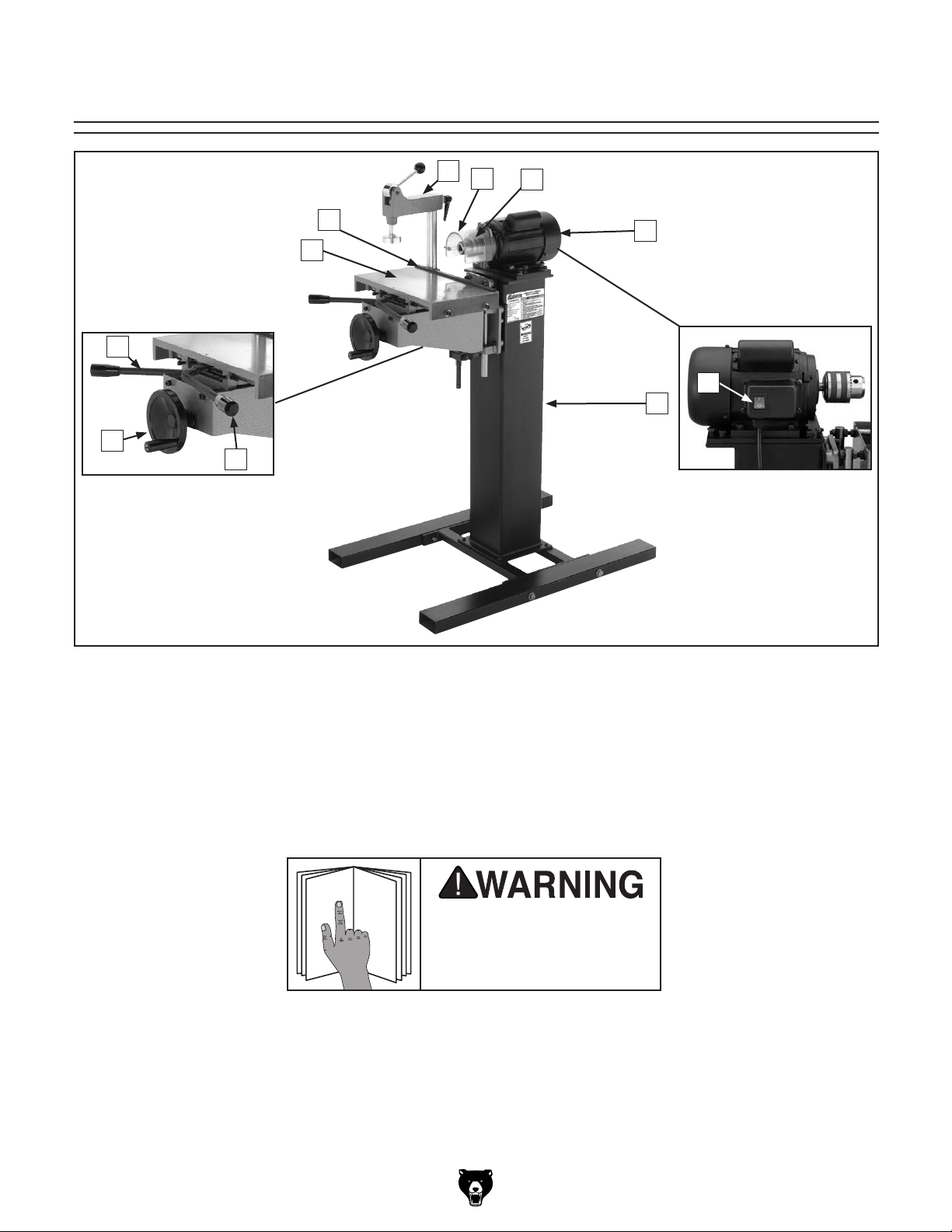
Figure 1. G0540 controls and features.
F
G
H
A. Work Table
B. Fence
C. Hold-Down Clamp
D. Chuck Guard
E. Chuck
F. Motor
G. ON/OFF Switch
H. Stand
I. Horizontal Adjustment Handle
J. Elevation Handwheel
K. Table Feed Handle
using machine.
Model G0540 (Mfg. Since 1/12)
-3-
Page 6

Machine Data Sheet
MACHINE DATA
SHEET
Customer Service #: (570) 546-9663 · To Order Call: (800) 523-4777 · Fax #: (800) 438-5901
MODEL G0540 SINGLE SPINDLE HORIZONTAL BORING
MACHINE
Product Dimensions:
Weight.............................................................................................................................................................. 189 lbs.
Width (side-to-side) x Depth (front-to-back) x Height..................................................................... 40-1/2 x 22 x 43 in.
Footprint (Length x Width)............................................................................................................... 22-1/4 x 31-1/2 in.
Shipping Dimensions:
Type.......................................................................................................................................................... Wood Crate
Content........................................................................................................................................................... Machine
Weight.............................................................................................................................................................. 201 lbs.
Length x Width x Height....................................................................................................................... 22 x 37 x 20 in.
Must Ship Upright................................................................................................................................................... Yes
Electrical:
Power Requirement........................................................................................................... 110V, Single-Phase, 60 Hz
Prewired Voltage.................................................................................................................................................. 110V
Full-Load Current Rating........................................................................................................................................ 12A
Minimum Circuit Size.............................................................................................................................................. 15A
Switch.................................................................................................................................................... Rocker Switch
Cord Length.......................................................................................................................................................... 10 ft.
Cord Gauge.................................................................................................................................................... 16 AWG
Plug Included.......................................................................................................................................................... Yes
Motors:
Main
Type................................................................................................................. TEFC Capacitor-Start Induction
Horsepower............................................................................................................................................. 3/4 HP
Phase............................................................................................................................................ Single-Phase
Amps............................................................................................................................................................ 12A
Speed................................................................................................................................................ 3450 RPM
Power Transfer ............................................................................................................................... Direct Drive
Bearings..................................................................................................... Shielded & Permanently Lubricated
Main Specifications:
Operation Information
Spindle RPM............................................................................................................................................... 3450
Drill Bit Type.................................................................................................................................... Chuck Type
Bit Cap...................................................................................................................................................... 5/8 in.
Table Information
Table Travel Vertical.............................................................................................................................. 2-1/8 in.
Table Travel Front To Back................................................................................................................... 4-1/8 in.
Table Travel Side To Side........................................................................................................................... 6 in.
Floor To Table Height............................................................................................................ 33-7/8 - 36-7/8 in.
Table Size Length................................................................................................................................ 14-1/4 in.
Table Size Width................................................................................................................................... 8-1/4 in.
-4-
Model G0540 (Mfg. Since 1/12)
Page 7

Construction
Table.................................................................................................................................................... Cast Iron
Table Vertical Slide.............................................................................................................................. Cast Iron
Base.......................................................................................................................... Heavy Duty Welded Steel
Body............................................................................................................................................ Steel/Cast Iron
Paint......................................................................................................................................................... Epoxy
Other Specifications:
Country Of Origin ............................................................................................................................................... China
Warranty ........................................................................................................................................................... 1 Year
Serial Number Location ................................................................................................................................. ID Label
Approximate Assembly & Setup Time .............................................................................................................. 1 Hour
Features:
Cam Action Hold Down Clamp
Table Moves on Ground Columns
See-Through Safety Guard
Adjustable Table Stops
Heavy Duty Stand
Model G0540 (Mfg. Since 1/12)
-5-
Page 8

SECTION 1: SAFETY
For Your Own Safety, Read Instruction
Manual Before Operating This Machine
The purpose of safety symbols is to attract your attention to possible hazardous conditions.
This manual uses a series of symbols and signal words intended to convey the level of importance of the safety messages. The progression of symbols is described below. Remember that
safety messages by themselves do not eliminate danger and are not a substitute for proper
accident prevention measures. Always use common sense and good judgment.
Indicates an imminently hazardous situation which, if not avoided,
WILL result in death or serious injury.
Indicates a potentially hazardous situation which, if not avoided,
COULD result in death or serious injury.
Indicates a potentially hazardous situation which, if not avoided,
MAY result in minor or moderate injury. It may also be used to alert
against unsafe practices.
This symbol is used to alert the user to useful information about
NOTICE
proper operation of the machine.
Safety Instructions for Machinery
OWNER’S MANUAL. Read and understand this
owner’s manual BEFORE using machine.
TRAINED OPERATORS ONLY. Untrained operators have a higher risk of being hurt or killed.
Only allow trained/supervised people to use this
machine. When machine is not being used, disconnect power, remove switch keys, or lock-out
machine to prevent unauthorized use—especially
around children. Make workshop kid proof!
DANGEROUS ENVIRONMENTS. Do not use
machinery in areas that are wet, cluttered, or have
poor lighting. Operating machinery in these areas
greatly increases the risk of accidents and injury.
MENTAL ALERTNESS REQUIRED. Full mental
alertness is required for safe operation of machinery. Never operate under the influence of drugs or
alcohol, when tired, or when distracted.
ELECTRICAL EQUIPMENT INJURY RISKS. You
can be shocked, burned, or killed by touching live
electrical components or improperly grounded
machinery. To reduce this risk, only allow qualified
service personnel to do electrical installation or
repair work, and always disconnect power before
accessing or exposing electrical equipment.
DISCONNECT POWER FIRST.
nect machine from power supply BEFORE making
adjustments, changing tooling, or servicing machine.
This prevents an injury risk from unintended startup
or contact with live electrical components.
EYE PROTECTION. Always wear ANSI-approved
safety glasses or a face shield when operating or
observing machinery to reduce the risk of eye
injury or blindness from flying particles. Everyday
eyeglasses are not approved safety glasses.
Always discon-
-6-
Model G0540 (Mfg. Since 1/12)
Page 9

WEARING PROPER APPAREL. Do not wear
clothing, apparel or jewelry that can become
entangled in moving parts. Always tie back or
cover long hair. Wear non-slip footwear to avoid
accidental slips, which could cause loss of workpiece control.
HAZARDOUS DUST. Dust created while using
machinery may cause cancer, birth defects, or
long-term respiratory damage. Be aware of dust
hazards associated with each workpiece material,
and always wear a NIOSH-approved respirator to
reduce your risk.
HEARING PROTECTION. Always wear hearing protection when operating or observing loud
machinery. Extended exposure to this noise
without hearing protection can cause permanent
hearing loss.
REMOVE ADJUSTING TOOLS. Tools left on
machinery can become dangerous projectiles
upon startup. Never leave chuck keys, wrenches,
or any other tools on machine. Always verify
removal before starting!
INTENDED USAGE. Only use machine for its
intended purpose and never make modifications
not approved by Grizzly. Modifying machine or
using it differently than intended may result in
malfunction or mechanical failure that can lead to
serious personal injury or death!
AWKWARD POSITIONS. Keep proper footing
and balance at all times when operating machine.
Do not overreach! Avoid awkward hand positions
that make workpiece control difficult or increase
the risk of accidental injury.
CHILDREN & BYSTANDERS. Keep children and
bystanders at a safe distance from the work area.
Stop using machine if they become a distraction.
FORCING MACHINERY. Do not force machine.
It will do the job safer and better at the rate for
which it was designed.
NEVER STAND ON MACHINE. Serious injury
may occur if machine is tipped or if the cutting
tool is unintentionally contacted.
STABLE MACHINE. Unexpected movement during operation greatly increases risk of injury or
loss of control. Before starting, verify machine is
stable and mobile base (if used) is locked.
USE RECOMMENDED ACCESSORIES. Consult
this owner’s manual or the manufacturer for recommended accessories. Using improper accessories will increase the risk of serious injury.
UNATTENDED OPERATION. To reduce the
risk of accidental injury, turn machine OFF and
ensure all moving parts completely stop before
walking away. Never leave machine running
while unattended.
MAINTAIN WITH CARE. Follow all maintenance
instructions and lubrication schedules to keep
machine in good working condition. A machine
that is improperly maintained could malfunction,
leading to serious personal injury or death.
CHECK DAMAGED PARTS. Regularly inspect
machine for any condition that may affect safe
operation. Immediately repair or replace damaged
or mis-adjusted parts before operating machine.
MAINTAIN POWER CORDS. When disconnecting cord-connected machines from power, grab
and pull the plug—NOT the cord. Pulling the cord
may damage the wires inside. Do not handle
cord/plug with wet hands. Avoid cord damage by
keeping it away from heated surfaces, high traffic
areas, harsh chemicals, and wet/damp locations.
GUARDS & COVERS. Guards and covers reduce
accidental contact with moving parts or flying
debris. Make sure they are properly installed,
undamaged, and working correctly.
Model G0540 (Mfg. Since 1/12)
EXPERIENCING DIFFICULTIES. If at any time
you experience difficulties performing the intended operation, stop using the machine! Contact our
Technical Support at (570) 546-9663.
-7-
Page 10

Additional Safety for Boring Machines
EYE/FACE/HAND PROTECTION. Debris from
the drilling operation can be thrown at the operator.
Always wear safety glasses or a face shield to protect your eyes and face during boring operations.
The spinning bit is sharp and can cause serious
injury. Always keep hands and fingers away from
the moving bit and the chuck. To reduce the risk of
entanglement, DO NOT wear gloves when operating this machine.
GUARDS. The chuck guard reduces the risk of
debris being thrown at the operator. DO NOT operate this machine with the guard removed.
BORING OPERATION. Boring bits rotate with tremendous torque, especially at start up. To avoid a
bit grabbing the workpiece and unexpectedly moving it, never start the machine with a bit pressed
against the workpiece.
BORING BITS. A rapidly spinning boring bit can
be thrown at the operator if it comes loose from the
chuck. Only use bits with a
the bits in the chuck before beginning operations.
5
⁄8" shank. Properly secure
DULL OR WORN BITS. Dull or damaged bits may
break apart during operation, be thrown at the
operator, or reduce the performance of the operation. Inspect the bit before each use. DO NOT
operate with a dull or damaged bit.
SECURING WORKPIECE. To keep the workpiece
from moving during boring operations, make sure
it is placed in a stable position on the table and
is secured by the hold-down clamp or additional
support fixtures.
SURFACE/WORKPIECE PREPARATION. Never
turn the machine ON before clearing the table of
all tools, scrap wood, etc. Only drill wood products
that are free of imperfections or foreign objects.
Never use this machine to drill metal.
Like all machinery there is potential danger
when operating this machine. Accidents are
frequently caused by lack of familiarity or
failure to pay attention. Use this machine
with respect and caution to decrease the
risk of operator injury. If normal safety precautions are overlooked or ignored, serious
personal injury may occur.
-8-
No list of safety guidelines can be complete.
Every shop environment is different. Always
consider safety first, as it applies to your
individual working conditions. Use this and
other machinery with caution and respect.
Failure to do so could result in serious personal injury, damage to equipment, or poor
work results.
Model G0540 (Mfg. Since 1/12)
Page 11

SECTION 2: POWER SUPPLY
Before installing the machine, consider the availability and proximity of the required power supply
circuit. If an existing circuit does not meet the
requirements for this machine, a new circuit must
be installed. To minimize the risk of electrocution,
fire, or equipment damage, installation work and
electrical wiring must be done by an electrican or
qualified service personnel in accordance with all
applicable codes and standards.
Electrocution, fire, or
equipment damage may
occur if machine is not
correctly grounded and
connected to the power
The full-load current rating is the amperage a
machine draws at 100% of the rated output power.
On machines with multiple motors, this is the
amperage drawn by the largest motor or sum of all
motors and electrical devices that might operate
at one time during normal operations.
The full-load current is not the maximum amount
of amps that the machine will draw. If the machine
is overloaded, it will draw additional amps beyond
the full-load rating.
If the machine is overloaded for a sufficient length
of time, damage, overheating, or fire may result—
especially if connected to an undersized circuit.
To reduce the risk of these hazards, avoid overloading the machine during operation and make
sure it is connected to a power supply circuit that
meets the requirements in the following section.
For your own safety and protection of
Note: The circuit requirements listed in this man-
ual apply to a dedicated circuit—where only one
machine will be running at a time. If this machine
will be connected to a shared circuit where multiple machines will be running at the same time,
consult a qualified electrician to ensure that the
circuit is properly sized for safe operation.
A power supply circuit includes all electrical
equipment between the breaker box or fuse panel
in the building and the machine. The power supply circuit used for this machine must be sized to
safely handle the full-load current drawn from the
machine for an extended period of time. (If this
machine is connected to a circuit protected by
fuses, use a time delay fuse marked D.)
This machine is prewired to operate on a power
supply circuit that has a verified ground and meets
the following requirements:
Availability
Serious injury could occur if you connect
the machine to power before completing the
setup process. DO NOT connect to power
until instructed later in this manual.
110V Circuit Requirements
Nominal Voltage .............................. 110V–120V
Cycle .......................................................... 60 Hz
Phase ........................................... Single-Phase
Power Supply Circuit ......................... 15 Amps
supply.
Full-Load Current Rating
Full-Load Current Rating at 110V ...... 12 Amps
Model G0540 (Mfg. Since 1/12)
property, consult an electrician if you are
unsure about wiring practices or electrical
codes in your area.
-9-
Page 12
Improper connection of the equipment-grounding
wire can result in a risk of electric shock. The
wire with green insulation (with or without yellow
stripes) is the equipment-grounding wire. If repair
or replacement of the power cord or plug is necessary, do not connect the equipment-grounding
wire to a live (current carrying) terminal.
Check with a qualified electrician or service personnel if you do not understand these grounding
requirements, or if you are in doubt about whether
the tool is properly grounded. If you ever notice
that a cord or plug is damaged or worn, disconnect it from power, and immediately replace it with
a new one.
We do not recommend using an extension cord
with this machine.
cord, only use it if absolutely necessary and only
on a temporary basis.
Extension cords cause voltage drop, which may
damage electrical components and shorten motor
life. Voltage drop increases as the extension cord
size gets longer and the gauge size gets smaller
(higher gauge numbers indicate smaller sizes).
Any extension cord used with this machine must
contain a ground wire, match the required plug
and receptacle, and meet the following requirements:
Grounding & Plug Requirements
it will not fit the outlet, have a qualified
electrician install the proper outlet with a
This machine MUST be grounded. In the event
of certain malfunctions or breakdowns, grounding
reduces the risk of electric shock by providing a
path of least resistance for electric current.
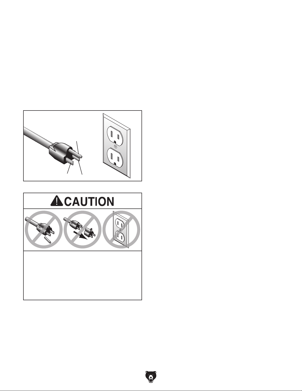
This machine is equipped with a power cord that
has an equipment-grounding wire and a grounding plug (similar to the figure below). The plug
must only be inserted into a matching receptacle
(outlet) that is properly installed and grounded in
accordance with all local codes and ordinances.
GROUNDED
5-15 RECEPTACLE
Grounding Prong
5-15 PLUG
Extension Cords
If you must use an extension
Neutral Hot
Figure 2. Typical 5-15 plug and receptacle.
SHOCK HAZARD!
Two-prong outlets do not meet the grounding
requirements for this machine. Do not modify
or use an adapter on the plug provided—if
verified ground.
-10 -
Minimum Gauge Size ...........................14 AWG
Maximum Length (Shorter is Better).......50 ft.
Model G0540 (Mfg. Since 1/12)
Page 13

SECTION 3: SETUP
Your machine was carefully packaged for safe
transportation. Remove the packaging materials
from around your machine and inspect it. If you
discover any damage, please call us immediately
at (570) 546-9663
Save the containers and all packing materials for
possible inspection by the carrier or its agent.
Otherwise, filing a freight claim can be difficult.
When you are completely satisfied with the condition of your shipment, inventory the contents.
Keep children and pets away
from plastic bags or packing
materials shipped with this
Unpacking
for advice.
SUFFOCATION HAZARD!
Needed for Setup
The following are needed to complete the setup
process, but are not included with your machine.
Description Qty
• Additional People ....................................... 1
• Safety Glasses ........................................... 1
• Cleaner/Degreaser (Page 14) .... As Needed
• Disposable Shop Rags ............... As Needed
• Screwdriver Phillips #2 ............................... 1
• Screwdriver Standard #2 ............................ 1
• Open-End Wrench 18mm ........................... 1
machine. Discard immediately.
Model G0540 (Mfg. Since 1/12)
-11-
Page 14

Hardware Recognition Chart
-12-
Model G0540 (Mfg. Since 1/12)
Page 15

Inventory
The following is a list of items shipped with your
machine. Before beginning setup, lay these items
out and inventory them.
If any non-proprietary parts are missing (e.g. a
nut or a washer), we will gladly replace them; or
for the sake of expediency, replacements can be
obtained at your local hardware store.
NOTICE
If you cannot find an item on this list, carefully check around/inside the machine and
packaging materials. Often, these items get
lost in packaging materials while unpacking or they are pre-installed at the factory.
Box 2 Contents (Figure 4) Qty
G. Chuck Guard .............................................. 1
H. Lock Handle ............................................... 1
I. Hold-Down Clamp ...................................... 1
J. Column ....................................................... 1
G
I
H
J
Figure 4. Box 2 inventory.
Box 1: (Figure 3) Qty
A. Cross Brace ................................................ 1
B. Table Assembly .......................................... 1
C. Motor .......................................................... 1
D. Stand .......................................................... 1
E. Legs ............................................................ 2
F. Handwheel Handle (Not Shown) ................ 1
C
B
D
A
Figure 3. Box 1 inventory.
E
Hardware and Tools Qty
• Hex Wrenches, 5, 6mm .............................. 2
• Chuck Key .................................................. 1
• Wrench 13 x 16 .......................................... 1
• Hex Bolts M10-1.5 x 100............................. 4
• Hex Bolts M10-1.5 x 40 .............................. 4
• Hex Bolts M12-1.75 x 70 ............................. 4
• Hex Bolts M8-1.25 x 25 .............................. 4
• Hex Bolts M8-1.25 x 20 .............................. 4
• Cap Screws M8-1.25 x 30 .......................... 2
• Cap Screws M8-1.25 x 35 ......................... 2
• Flat Washers 10mm ................................... 8
• Lock Washers 10mm .................................. 8
• Flat Washers 8mm ..................................... 8
• Lock Washers 8mm.................................... 8
• Hex Nuts M12-1.75 ..................................... 4
Model G0540 (Mfg. Since 1/12)
-13-
Page 16

The unpainted surfaces of your machine are
coated with a heavy-duty rust preventative that
prevents corrosion during shipment and storage.
This rust preventative works extremely well, but it
will take a little time to clean.
Be patient and do a thorough job cleaning your
machine. The time you spend doing this now will
give you a better appreciation for the proper care
of your machine's unpainted surfaces.
There are many ways to remove this rust preventative, but the following steps work well in a wide
variety of situations. Always follow the manufacturer’s instructions with any cleaning product you
use and make sure you work in a well-ventilated
area to minimize exposure to toxic fumes.
Before cleaning, gather the following:
• Disposable Rags
• Cleaner/degreaser (WD•40 works well)
• Safety glasses & disposable gloves
• Plastic paint scraper (optional)
Basic steps for removing rust preventative:
1.
2.
3.
4.
Many cleaning solvents
work in a well-ventilated
Avoid chlorine-based solvents, such as
Cleanup
Gasoline and petroleum
products have low flash
points and can explode
or cause fire if used to
clean machinery. Avo id
using these products
to clean machinery.
Put on safety glasses.
Coat the rust preventative with a liberal
amount of cleaner/degreaser, then let it soak
for 5–10 minutes.
Wipe off the surfaces. If your cleaner/degreas-
er is effective, the rust preventative will wipe
off easily. If you have a plastic paint scraper,
scrape off as much as you can first, then wipe
off the rest with the rag.
are toxic if inhaled. Only
area.
NOTICE
acetone or brake parts cleaner, that may
damage painted surfaces.
T23692—Orange Power Degreaser
A great product for removing the waxy shipping
grease from your machine during clean up.
Figure 5. T23692 Orange Power Degreaser.
Repeat Steps 2–3 as necessary until clean,
then coat all unpainted surfaces with a quality
metal protectant to prevent rust.
-14-
Model G0540 (Mfg. Since 1/12)
Page 17

Site Considerations
Weight Load
Physical Environment
Place this machine near an existing power source.
Shadows, glare, or strobe effects that may distract
Refer to the Machine Data Sheet for the weight
of your machine. Make sure that the surface upon
which the machine is placed will bear the weight
of the machine, additional equipment that may be
installed on the machine, and the heaviest workpiece that will be used. Additionally, consider the
weight of the operator and any dynamic loading
that may occur when operating the machine.
Space Allocation
Consider the largest size of workpiece that will
be processed through this machine and provide
enough space around the machine for adequate
operator material handling or the installation of
auxiliary equipment. With permanent installations,
leave enough space around the machine to open
or remove doors/covers as required by the maintenance and service described in this manual.
See below for required space allocation.
Children or untrained people
may be seriously injured by
this machine. Only install in an
access restricted location.
The physical environment where the machine is
operated is important for safe operation and longevity of machine components. For best results,
operate this machine in a dry environment that is
free from excessive moisture, hazardous chemicals, airborne abrasives, or extreme conditions.
Extreme conditions for this type of machinery are
generally those where the ambient temperature
range exceeds 41°–104°F; the relative humidity
range exceeds 20–95% (non-condensing); or the
environment is subject to vibration, shocks, or
bumps.
Electrical Installation
Make sure all power cords are protected from
traffic, material handling, moisture, chemicals,
or other hazards. Make sure to leave access to
a means of disconnecting the power source or
engaging a lockout/tagout device, if required.
Lighting
Lighting around the machine must be adequate
enough that operations can be performed safely.
or impede the operator must be eliminated.
Model G0540 (Mfg. Since 1/12)
44"
28"
Figure 6. Minimum working clearances.
-15-
Page 18
Mounting
they stick out of the floor—permanently.
Although not required, we recommend that you
mount your new machine to the floor. Use the four
holes in the legs as a guide for drilling.
Stand, Cross Brace
& Legs
To install the stand onto the cross brace:
Because this is an optional step and floor materials may vary, floor mounting hardware is not
included. To ensure accurate operation results,
make sure your mounting location is as level as
possible and that you provide adequate work
room all around the boring machine. Use metal
shims to level the machine, if necessary.
Bolting to Concrete Floors
Lag shield anchors with lag screws and anchor
studs (Figure 7) are two popular methods for
anchoring an object to a concrete floor. We suggest you research the many options and methods
for mounting your machine and choose the best
that fits your specific application.
Anchor Stud
1. Place the cross brace on a flat surface.
2. Position the two legs perpendicular to the
cross brace, making sure the mounting holes
are aligned.
3. Fasten the legs to the cross brace with four
M10-1.5 x 100 hex bolts, 10mm lock washers, and 10mm flat washers, as shown in
Figure 8.
Cross Brace
x4
Leg
Lag Shield
Anchor
Lag Screw
Figure 7. Typical fasteners for mounting to
concrete floors.
NOTICE
Anchor studs are the strongest option, but
Before using, make sure you have enough
clearance to lift the machine over the studs
if it must be moved in the future.
Figure 8. Fastening legs to cross brace.
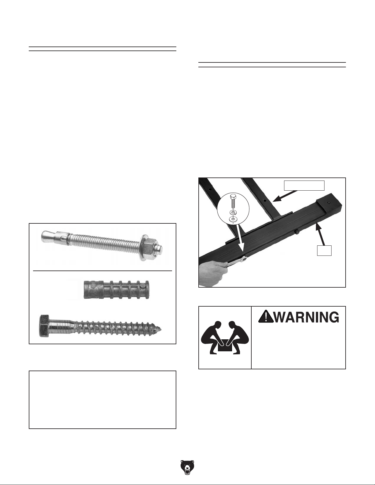
BACK INJURY HAZARD!
DO NOT over-exert yourself
moving your machine—get
assistance during the next
step.
-16 -
Model G0540 (Mfg. Since 1/12)
Page 19

4. Turn the stand upside down and place the
cross brace on the stand bottom, as shown
in Figure 9.
Table Assembly
Note: The leg pads should face up and the
longer length of the legs should be on the
same side as the table mounting plate.
Leg Mounting Hole
x4
Shorter
Table
Mounting
Plate
Leg
Pad
Figure 9. Installing cross brace onto stand.
5. Align the mounting holes and secure with four
M10-1.5 x 40 hex bolts, 10mm lock washers,
and 10mm flat washers, as shown in Figure 9.
Length
Longer
Length
To install the table assembly:
1. With another person's help, place the stand
on its back, place the table assembly on the
table plate, and align the mounting holes (see
Figure 10).
Table
x2
Stand
Figure 10. Mounting bottom of table assembly to
Assembly
Table
Plate
stand.
Note: Do not install the hex bolts from the top
of the cross brace. The stand will be unstable
and may tip over. The bolts must be installed
through the bottom of the cross brace.
6. Inspect the leg mounting holes (see Figure
9) and remove any extra paint or metal debris
from the threads.
BACK INJURY HAZARD!
DO NOT over-exert yourself
moving your machine—get
assistance during the next
step.
2. Fasten the bottom of the table assembly to
the stand with two M8-1.25 x 35 cap screws,
8mm lock washers, and 8mm flat washers, as
shown in Figure 10.
3. Fasten the top of the table assembly to the
stand with two M8-1.25 x 30 cap screws,
8mm lock washers, and 8mm flat washers, as
shown in Figure 11.
x2
Model G0540 (Mfg. Since 1/12)
Figure 11. Mounting top of table assembly to
stand.
-17-
Page 20

4. Mount the machine to the floor (refer to
Mounting on Page 16), or insert the four
M12-1.75 x 70 hex bolts through the leg
mounting holes, as shown in Figure 12.
Motor
To install the motor onto the stand:
Hex Bolt
Hex Nut
Figure 12. Leveling leg with hex bolts.
5. Thread an M12-1.75 hex nut onto each hex
bolt (see Figure 12) and continue threading
the bolts through the bottom mounting holes
until they touch the floor.
6. Adjust the hex bolts up or down to level the
legs, as necessary.
1. Place the motor mounting plate over the
stand and align the mounting holes.
2. Secure the motor mounting plate and stand
with four M8-1.25 x 25 hex bolts, 8mm lock
washers and 8mm flat washers, as shown in
Figure 13.
x4
Figure 13. Mounting motor plate to stand.
7. Thread the handwheel handle onto the
handwheel.
8. With another person's help, place the machine
upright.
3. Thread four M8-1.25 x 20 hex bolts several
turns into the outer holes of the motor mounting plate (see 14).
x4
Figure 14. Hex bolts threaded into mounting
plate (only one side shown).
-18-
Model G0540 (Mfg. Since 1/12)
Page 21

Chuck Guard
Test Run
To install the chuck guard:
1. Loosen the Phillips head screw and hex nut
on the chuck guard clamp.
2. Install the chuck guard over the motor spindle
with the springs up, and tighten the Phillips
head screw and hex nut (see Figure 15).
Figure 15. Installing chuck guard.
Once the assembly is complete, test run your
machine to make sure it runs properly.
If, during the test run, you cannot easily locate
the source of an unusual noise or vibration, stop
using the machine immediately, then review the
Troubleshooting on Page 27.
If you still cannot remedy a problem, contact our
Tech Support at (570) 546-9663 for assistance.
To test run the machine:
1. Make sure you have read the safety instruc-
tions at the beginning of the manual and that
the machine is set up properly.
2. Make sure all tools and objects used during
setup are cleared away from the machine.
3. Connect the machine to the power source.
4. Turn the machine ON.
Hold-Down Clamp
To install the hold-down clamp:
1. Thread the column onto the work table (see
Figure 16).
Lock
Handle
Column
Arm
Work
Table
Figure 16. Installing hold-down clamp.
2. Thread the lock handle onto the arm (see
Figure 16), slide the arm onto the column,
then tighten the lock handle.
5. Listen to and watch for abnormal noises or
actions. The machine should run smoothly
with little or no vibration or rubbing noises.
— Strange or unusual noises should be inves-
tigated and corrected before operating the
machine further. Always disconnect the
machine from power when investigating or
correcting potential problems.
6. Turn the machine OFF.
Model G0540 (Mfg. Since 1/12)
-19 -
Page 22

SECTION 4: OPERATIONS
The purpose of this overview is to provide the novice machine operator with a basic understanding
of how the machine is used during operation, so
the
discussed later
in this manual
Due to the generic nature of this overview, it is
not intended to be an instructional guide. To learn
more about specific operations, read this entire
manual and
rienced
research outside of this manual by reading "howto" books, trade magazines, or websites.
To reduce your risk of
serious injury, read this
entire manual BEFORE
To reduce risk of eye injury from flying
Operation Overview
To complete a typical operation, the operator
does the following:
1. Installs the appropriate bit for the boring
operation.
machine controls/components
are easier to understand.
seek additional training from expe
machine operators, and do additional
using machine.
chips or lung damage from breathing dust,
always wear safety glasses and a respirator
when operating this machine.
2. Places the workpiece flush against the table
and the fence.
3. Uses the handles and handwheel to align the
desired drilling location on the workpiece with
the bit.
4. Secures the workpiece with the hold-down
clamp.
5. Puts on safety glasses and a respirator.
6. Turns the machine ON.
AMPUTAT I ON HA ZAR D
Keep hands and body
away from the spinning
boring bits!
7. Uses the table feed handle to move the
workpiece into the bit, drills the hole, then
moves the workpiece out of the bit.
If you are not experienced with this type
of machine, WE STRONGLY RECOMMEND
that you seek additional training outside of
this manual. Read books/magazines or get
formal training before beginning any projects. Regardless of the content in this section, Grizzly Industrial will not be held liable
for accidents caused by lack of training.
-20-
8. Uses the horizontal adjustment handle to
move the workpiece left-to-right for additional
boring operations.
9. Turns the machine OFF when boring opera-
tions are complete.
10. Unclamps the workpiece.
Model G0540 (Mfg. Since 1/12)
Page 23

Basic Controls
A. Horizontal Adjustment Handle: Moves the
work table left-to-right.
Refer to Figures 17–18 and the following descriptions to become familiar with the basic controls of
this machine.
D
E
C
B
A
Figure 17. Main controls.
B. Elevation Handwheel: Moves the work table
up or down.
C. Table Feed Handle: Moves the work table
front-to-back.
D. Chuck Guard: Adjustable plastic shield cov-
ering the chuck that minimizes exposure to
sharp drill bits.
E. Hold-Down Clamp: Secures the workpiece
firmly against the table. Adjusts to accommodate different workpiece thicknesses, and is
secured with the lock handle.
F. ON/OFF Switch: Starts and stops motor.
Operating Tips
Here are a few things you can do to ensure easy
operation and excellent workpiece results:
F
Figure 18. ON/OFF switch
• Use the right bit for the job.
• Never rush a drilling procedure. Extra care
during set up will ensure satisfactory results.
• Maintain your horizontal boring machine in
top condition. See Section 6: Maintenance
beginning on see Page 25 for maintenance
procedures.
• Always use a test piece of wood to check
your setup. Only when desired results are
achieved, should you use your expensive
lumber.
• Always clamp your workpiece.
Model G0540 (Mfg. Since 1/12)
-21-
Page 24

Drill Bit Changes
Table Adjustments
The Model G0540 chuck can hold up to 5⁄8"
bits. To insert a bit, care must be taken to
secure the bit firmly in place. When changing bits follow the instructions below.
To install a drill bit:
1. DISCONNECT MACHINE FROM POWER!
2. Open the chuck guard.
3. Using the chuck key, adjust the chuck jaws
as needed to accommodate the drill bit shaft.
4. Install the bit into the chuck, but do not allow
it to grab the flutes of the drill bit. Also, ensure
small drill bits do not get trapped between the
jaw edges.
5. Tighten the chuck, remove the chuck key,
then close the chuck guard.
6. Re-connect the machine to power.
To remove a drill bit:
Adjust table stop rods to set the maximum distance the table can move left-to-right and back
and forth.
To adjust the front stop rods:
1. Loosen the cap screws that secure the front
stop rods (see Figure 19), and move the rods
left or right to set the maximum horizontalmovement.
Cap Screw
Figure 19. Front stop rod adjustments.
2. Tighten the cap screws and move the hori-
zontal handle to test the stop rod positions.
Stop Rod (1 of 2)
1. DISCONNECT MACHINE FROM POWER!
2. Open the chuck guard, loosen the chuck,
grasp the bit with your hand, then remove it.
3. Repeat Steps 1–2 as necessary.
To adjust the center stop rod:
1. Loosen the cap screw shown in Figure 20
and adjust the center stop rod.
Stop Rod
Cap Screw
Figure 20. Adjusting center stop rod.
2. Tighten the cap screw, and move the table
feed handle back and forth to test the center
stop rod position.
-22-
3. Repeat Steps 1–2 as necessary.
Model G0540 (Mfg. Since 1/12)
Page 25

ACCESSORIES
Installing unapproved accessories may
order online at www.grizzly.com or call 1-800-523-4777
SECTION 5: ACCESSORIES
cause machine to malfunction, resulting in
serious personal injury or machine damage.
To reduce this risk, only install accessories
recommended for this machine by Grizzly.
NOTICE
Refer to our website or latest catalog for
additional recommended accessories.
G9753—TiN Coated Drill Set 50-Pc. Metric
G9754 —TiN Coated Drill Bits 60-Pc. Set
G9755 —TiN Coated Drill Bits 26-Pc. Set
These long lasting HSS, TiN coated bits are available in either a 60 piece numbered bit set or 26
piece lettered bit set. Numbered bits range from
1 to 60. Lettered bits range from A to Z. Sets
include steel drill indexes. 50 piece set includes
1mm through 6mm inch 0.1mm increments plus
steel index.
G3656—Titanium Drill Bits 29-Pc. Set
G3658—Titanium Drill Bits 115-Pc. Set
Titanium nitride coated bits last up to six times as
long as uncoated bits. 29-piece set includes bits
ranging from
115-piece set features 29 fractional bits from
1
⁄2" inch increments of 1⁄64", letter bits from A to Z
to
and 60 number bits. Housed in rugged steel case.
G3656
Figure 22. Models G3656 & G3658 Titanium Drill
1
⁄16" to 1⁄2" inch increments of 1⁄64".
G3658
Bit Sets.
1
⁄16"
Figure 21. Model G9753 50-Pc. TiN Coated Bit
Set.
D1032—Steelex Carbide-Tipped Brad Point Bit
7-Pc. Set
This is the best set of brad point bits on the market. Set includes:
1
⁄2 ". Comes in a wooden case.
Figure 23. Model D1032 Brad Point Bit 7-Pc.
1
⁄8", 3⁄16", 1⁄4", 5⁄16", 3⁄8", 7⁄16" and
set.
Model G0540 (Mfg. Since 1/12)
-23-
Page 26

G9756—End Mill Set 20-Pc.
order online at www.grizzly.com or call 1-800-523-4777
This High Speed Steel set features 2 flute and 4
flute end cutting end mills in the following sizes:
3
⁄16", 1⁄4", 5⁄16", 3⁄8", 7⁄16", 1⁄2 ", 9⁄16", 5⁄8", 11⁄16" and 3⁄4".
Sizes are marked in a durable molded case.
Figure 24. Model G9756 20-Pc. HSS End Mill
Set.
G3875—
3
⁄8" x 11⁄2" Dowel Pins–500
These computer-inspected dowel pins meet the
demanding standards of high-speed drilling and
dowel-driving equipment. Pins are chamfered for
easy insertion and grooved for even glue distribution. Straight flutes are superior over spiral grooves
as they virtually eliminate hydraulic pressure
build up that can split joints. Made in the U.S.A.
Recommended Metal Protectants
G5562—SLIPIT® 1 Qt. Gel
G5563—SLIPIT
Figure 26. Recommended products for protect-
ing unpainted cast iron/steel parts on machinery.
G4682—Dry Coating Lube 9.5 oz.
Spray on saw blades, router bits, shaper cutters even table tops - to form a low friction coating that
works great, even under high temperature and
pressure. Contains no silicone or oil, so it won't
stain or damage paint or wood finishes. 9.5 oz.
®
12 oz. Spray
Figure 27. G4682 Dry Coating Lube.
Figure 25. Model G3875 Dowel Pins.
-24-
Model G0540 (Mfg. Since 1/12)
Page 27

SECTION 6: MAINTENANCE
accidental startup, always
disconnect machine from
Unpainted Cast Iron
To reduce risk of shock or
Protect the unpainted cast iron surfaces on the
power before adjustments,
maintenance, or service.
table by wiping the table clean after every use—
this ensures moisture from wood dust does not
remain on bare metal surfaces.
Schedule
For optimum performance from your machine,
follow this maintenance schedule and refer to any
specific instructions given in this section.
Daily Maintenance:
• Check for loose mounting bolts.
• Check for worn or damaged bits.
• Check for worn or damaged wires.
• Check for any other unsafe condition.
Weekly/Monthly Maintenance:
• Clean/vacuum wood chips and sawdust off of
motor.
• Lubricate travel rods, table leadscrew, and
hold-down clamp (see Page 26).
Cleaning
Keep tables rust-free with regular applications of products like SLIPIT
Accessories on see Page 24 for more details).
®
(see Section 5:
Bit Care
A horizontal boring machine bit requires proper
care.
• Store the bits so their sharp points and flutes
are protected. A wooden or plastic box that
keeps bits from touching one another works
best.
• Keep bits clean and rust free.
• Have bits sharpened as soon as they show
any signs of dulling.
Cleaning the Model G0540 is relatively easy.
Vacuum excess wood chips and sawdust, and
wipe off the remaining dust with a dry cloth. If any
resin has built up, use a resin dissolving cleaner
to remove it. Treat all unpainted cast iron and steel
with a non-staining lubricant after cleaning.
Model G0540 (Mfg. Since 1/12)
-25-
Page 28

Lubrication
It is essential to clean components before lubricating them because dust and chips build up on
lubricated components and make them hard to
move. Simply adding more lubricant to dirty components will not yield smooth movement.
Leadscrew
Clean the components in this section with mineral
spirits, a rag, or a bristle brush as directed.
The following are the main components that
need to be lubricated:
• Travel rods
• Table leadscrew
• Hold-down clamp
Always disconnect power
to the machine before performing lubrication. Failure
to do this may result in serious personal injury.
Travel Rods
Perform monthly. Clean sawdust and debris from
the table feed rods and vertical travel rods, and
horizontal travel rod (see Figures 28–30) with
mineral spirits and a rag. Apply a thin coat of dry
spray lubricant, such as Model G4682 (refer to
Page 24) to the slides. Move the table through
the entire range of motion to evenly distribute the
lubricant.
Vertical Travel Rods
Figure 29. Vertical travel rods and leadscrew.
Horizontal Travel Rod
Figure 30. Horizontal travel rod.
Table Leadscrew
Perform monthly. Use a stiff bristle brush and
mineral spirits to clean grime and debris from the
leadscrew (see Figures 29). Apply a thin coat
of dry spray lubricant to the leadscrew. Turn the
elevation handwheel to move the table assembly
through its entire vertical range the of motion to
evenly distribute the lubricant.
Hold-Down Clamp
Perform monthly. Apply a drop of light machine oil
to the cam (see Figure 31).
-26-
Table Feed
Rods
Figure 31. Location to oil hold-down clamp cam.
Figure 28. Table feed travel rods.
Model G0540 (Mfg. Since 1/12)
Page 29

Review the troubleshooting and procedures in this section if a problem develops with your machine. If you
need replacement parts or additional help with a procedure, call our Technical Support at (570) 546-9663.
Note: Please gather the serial number and manufacture date of your machine before calling.
SECTION 7: SERVICE
Troubleshooting
Motor & Electrical
Symptom Possible Cause Possible Solution
Machine does not
start or a breaker
trips.
Machine has
vibration or noisy
operation.
Machine slows or
stalls.
1. Plug/receptacle is at fault or wired
incorrectly.
2. Motor connection wired incorrectly.
3. Power supply switched OFF or is at fault.
4. Start capacitor is at fault.
5. Wall fuse/circuit breaker is blown/tripped.
6. Wiring is open/has high resistance.
7. Power ON/OFF switch is at fault.
8. Centrifugal switch is at fault.
9. Motor is at fault.
1. Bit or chuck not mounted correctly.
2. Machine is incorrectly mounted or sits
unevenly on floor.
3. Motor mount loose.
4. Motor or component is loose.
5. Motor fan is rubbing on fan cover.
6. Centrifugal switch is at fault.
1. Workpiece material is not suitable for this
machine, or machine undersized for the
task.
2. Motor connection is wired incorrectly.
3. Plug/receptacle is at fault.
4. Motor or boring head bearings are at fault.
5. Centrifugal switch is at fault.
6. Motor has overheated.
7. Motor is at fault.
1. Test for good contacts; correct the wiring.
2. Correct motor wiring connections.
3. Ensure power supply is switched ON; ensure power
supply has the correct voltage.
4. Test/replace if faulty.
5. Ensure circuit size is suitable for this machine;
replace weak breaker.
6. Check for broken wires or disconnected/corroded
connections, and repair/replace as necessary.
7. Replace faulty ON/OFF switch.
8. Adjust/replace the centrifugal switch if available.
9. Test/repair/replace.
1. Remove and re-install bit or chuck (Page 22).
2. Tighten/replace fasteners; relocate/shim machine.
3. Tighten.
4. Inspect/replace stripped or damaged bolts/nuts, and
re-tighten with thread locking fluid.
5. Replace dented fan cover; replace loose/damaged
fan.
6. Replace centrifugal switch.
1. Only drill wood products; make sure moisture
content is below 20% and use sharp bits/reduce
downfeed rate.
2. Correct motor wiring connections.
3. Test for good contacts; correct the wiring.
4. Replace bearings.
5. Adjust/replace centrifugal switch.
6. Clean off motor, let cool, and reduce workload.
7. Test/repair/replace.
Operation
Symptom Possible Cause Possible Solution
Machine slows when
operating.
Holes not drilled
straight into
workpiece.
Model G0540 (Mfg. Since 1/12)
1. Applying too much pressure to
workpiece.
2. Bits are dull.
1. Motor is not parallel to the table. 1. Adjust motor-table parallelism (Page 28).
1. Feed workpiece slower; use less pressure.
2. Replace bits.
-27-
Page 30

Adjusting Motor-
Table Parallelism
The motor and chuck axis are adjusted parallel to
the table by the factory. However, if these components are not parallel, perform the following
procedure.
Tools Needed Qty
Straightedge ...................................................... 1
Drill Rod............................................................. 1
Open-End Wrench 13 mm .................................. 1
To verify motor-table parallelism:
4. Tighten or loosen the front and rear adjusting
bolts (see Figure 33) in pairs as needed to
raise or lower the front or back of the motor.
Note: Before performing this step, make sure
the adjusting bolts barely touch the top of the
stand.
Front
Adjusting
Bolts
Mounting Bolt
(1 of 4)
1. Mount a piece of drill rod (round, straight
metal) in the chuck.
2. Raise the table just under the drill rod (Figure
32), and use a metal straightedge as a visual
reference for checking the front-to-back distance between the drill rod and the table.
Drill Rod
Figure 32. Checking table-motor parallelism.
—If a gap is not visible between the ruler
and the drill rod along its length, no adjustments are necessary. The motor is parallel
to the table.
Rear
Adjusting Bolt
(1 of 2)
Figure 33. Bolts for adjusting motor angle.
5. Repeat Step 2, and adjust the motor as
needed until it is parallel to the table.
6. Re-tighten the mounting bolts.
— If a gap is visible between the ruler and
the drill rod, the motor is not parallel to the
table. Proceed to the next step.
3. Loosen the four mounting bolts that secure
the motor to the stand (see Figure 33).
-28-
Model G0540 (Mfg. Since 1/12)
Page 31

These pages are current at the time of printing. However, in the spirit of improvement, we may make changes to the electrical systems of future machines. Compare the manufacture date of your machine to the one
number and manufacture date of your
machine before calling. This information can be found on the main machine label.
machine
SECTION 8: WIRING
stated in this manual, and study this section carefully.
If there are differences between your machine and what is shown in this section, call Technical Support at
(570) 546-9663 for assistance BEFORE making any changes to the wiring on your machine. An updated
wiring diagram may be available. Note: Please gather the serial
Wiring Safety Instructions
SHOCK HAZARD. Working on wiring that is connected to a power source is extremely dangerous.
Touching electrified parts will result in personal
injury including but not limited to severe burns,
electrocution, or death. Disconnect the power
from the machine before servicing electrical components!
MODIFICATIONS. Modifying the wiring beyond
what is shown in the diagram may lead to unpredictable results, including serious injury or fire.
This includes the installation of unapproved aftermarket parts.
WIRE CONNECTIONS. All connections must
be tight to prevent wires from loosening during
machine operation. Double-check all wires disconnected or connected during any wiring task to
ensure tight connections.
CIRCUIT REQUIREMENTS. You MUST follow
the requirements at the beginning of this manual when connecting your machine to a power
source.
WIRE/COMPONENT DAMAGE. Damaged wires
or components increase the risk of serious personal injury, fire, or machine damage. If you notice
that any wires or components are damaged while
performing a wiring task, replace those wires or
components.
MOTOR WIRING. The motor wiring shown in
these diagrams is current at the time of printing
but may not match your machine. If you find this
to be the case, use the wiring diagram inside the
motor junction box.
CAPACITORS/INVERTERS. Some capacitors
and power inverters store an electrical charge for
up to 10 minutes after being disconnected from
the power source. To reduce the risk of being
shocked, wait at least this long before working on
capacitors.
EXPERIENCING DIFFICULTIES. If you are experiencing difficulties understanding the information
included in this section, contact our Technical
Support at (570) 546-9663.
Model G0540 (Mfg. Since 1/12)
-29-
Page 32

Wiring Diagram
Start Capacitor
Ground
Green (Ground)
Motor
Wires
Switch
Power Cord
Wiring Box
-30-
READ ELECTRICAL SAFETY
ON PAGE 29!
Model G0540 (Mfg. Since 1/12)
Page 33

Motor
Electrical Components
Ground
(Green)
Motor
Wires
White
Wiring Box
Black
Switch
Power Cord
Figure 34. Switch and motor wiring.
Motor
Model G0540 (Mfg. Since 1/12)
Start Capacitor
Switch
Figure 35. Capacitor wiring.
READ ELECTRICAL SAFETY
-31-
ON PAGE 29!
Page 34

SECTION 9: PARTS
Please Note: We do our best to stock replacement parts whenever possible, but we cannot guarantee that all parts shown here
are available for purchase. Call (800) 523 - 4777 or visit our online parts store at www.grizzly.com to check for availability.
Main Parts Breakdown
26
74
75
71
48-1
22
32
23
31
73
24V2
78
72
65
30
27
28
64
29
34
35
38
25V2
33
36
37
13
63
48
8
50
12
11
10
62
57
55
69
52
9
77
14
70
1
2
67
3
4
48-2
49
5
59
66
6
66
63
50
51
53
54
76
79
58
15
16
60
47
16
17 18
46
50
62
56
45
44
19
43
40
39
42
50
50
63
20
32
41
30
21
16
61
63
48-5
48-4
48-3
-32-
57
68
Model G0540 (Mfg. Since 1/12)
Page 35

Main Parts List
REF PART # DESCRIPTION REF PART # DESCRIPTION
1 P0540001 ECCENTRIC HAND LEVER 44 P0540044 TABLE MOUNTING PLATE
2 P0540002 ALIGNMENT PIN 8 X 43 45 P0540045 STUD-UDE M12-1.75 X 19, M10-1.5 X 12, 137
3 P0540003 COLUMN M16-2 X 20 46 PN03M HEX NUT M8-1.25
4 P0540004 LOCK HANDLE M10-1.5 X 25 47 PSS03M SET SCREW M6-1 X 8
5 P0540005 HOLD-DOWN CLAMP ARM 48 P0540A12 MOTOR 3/4HP 110V 1-PH
6 P0540006 PRESS PLATE 48-1 P0540048-1 SWITCH
8 P0540008 FENCE 48-2 P0540048-2 WIRING BOX COVER
9 PS03M PHLP HD SCR M6-1 X 8 48-3 P0540048-3 CENTRIFUGAL SWITCH
10 P0540010 BLOCK RING 14MM 48-4 P0540048-4 FAN
11 P0540011 PRESS ROD 48-5 P0540048-5 FAN COVER
12 P0540012 COMPRESSION SPRING .5 X 18 X 55 49 PB07M HEX BOLT M8-1.25 X 25
13 PR02M EXT RETAINING RING 14MM 50 PW01M FLAT WASHER 8MM
14 P0540014 WORK TABLE 51 P0540051 MOTOR PLATE
15 P0540015 CONNECTING SEAT 52 PCAP61M CAP SCREW M10-1.5 X 20
16 P0540016 STOP ROD 53 PB140M HEX BOLT M12-1.75 X 70
17 P0540017 X-AXIS SHAFT 54 PN09M HEX NUT M12-1.75
18 PB08M HEX BOLT M6-1 X 20 55 PB31M HEX BOLT M10-1.5 X 40
19 PCAP50M CAP SCREW M5-.8 X 10 56 PB23M HEX BOLT M10-1.5 X 100
20 P0540020 COVER 57 PW04M FLAT WASHER 10MM
21 P0540021 Y-AXIS SHAFT 58 P0540058 STAND
22 PCAP14M CAP SCREW M8-1.25 X 20 59 P0540059 S CAPACITOR 12M 400V 1-1/4 X 2-3/4
23 P0540023 TABLE SUPPORT 60 P0540060 STAND CROSSBRACE
24V2 P0540024V2 PLATE 12.3MM HOLE V2.01.12 61 PCAP13M CAP SCREW M8-1.25 X 30
25V2 P0540025V2 ELEVATION HANDWHEEL SHAFT V2.01.12 62 PLW06M LOCK WASHER 10MM
26 P0540026 ELEVATION HANDWHEEL 125 X 12MM 63 PLW04M LOCK WASHER 8MM
27 P0540027 HANDWHEEL HANDLE M8-1.25 X 63 64 PLW03M LOCK WASHER 6MM
28 PCAP01M CAP SCREW M6-1 X 16 65 PW03M FLAT WASHER 6MM
29 P0540029 KNOB M12- 1.75 66 PB07M HEX BOLT M8-1.25 X 25
30 P0540030 HANDLE M12-1.75 X 25 67 PR39M EXT RETAINING RING 8MM
31 PCAP06M CAP SCREW M6-1 X 25 68 P0540068 LEG
32 PCAP40M CAP SCREW M8-1.25 X 35 69 P0540069 CHUCK 3-16MM JT33
33 P0540033 L-BRACKET 70 P0540070 CHUCK GUARD
34 P0540034 VERTICAL LEADSCREW 71 P0540071 CAPACITOR COVER
35 P0540035 LEADSCREW PLATE 72 PR03M EXT RETAINING RING 12MM
36 PN02M HEX NUT M10-1.5 73 PK48M KEY 4 X 4 X 20
37 PSS10M SET SCREW M10-1.5 X 20 74 PCAP50M CAP SCREW M5-.8 X 10
38 P0540038 LEADSCREW BLOCK 75 PW02M FLAT WASHER 5MM
39 P51100 THRUST BEARING 51100 76 P0540076 MACHINE ID LABEL
40 P0540040 GEAR 77 PLABEL-11A SAFETY GLASSES LABEL
41 PRP39M ROLL PIN 4 X 20 78 PPAINT-1 GRIZZLY GREEN TOUCH-UP PAINT
42 P0540042 COVER 79 P0540075 BLACK TOUCH-UP PAINT
43 P0540043 Z-AXIS SHAFT
Model G0540 (Mfg. Since 1/12)
-33-
Page 36

-34-
Model G0540 (Mfg. Since 1/12)
Page 37

WARRANTY CARD
Name _____________________________________________________________________________
Street _____________________________________________________________________________
City _______________________ State _________________________ Zip _____________________
Phone # ____________________ Email _________________________________________________
Model # ____________________ Order # _______________________ Serial # __________________
The following information is given on a voluntary basis. It will be used for marketing purposes to help us develop
better products and services. Of course, all information is strictly confidential.
1. How did you learn about us?
____ Advertisement ____ Friend ____ Catalog
____ Card Deck ____ Website ____ Other:
2. Which of the following magazines do you subscribe to?
____ Cabinetmaker & FDM
____ Family Handyman
____ Hand Loader
____ Handy
____ Home Shop Machinist
____ Journal of Light Cont.
____ Live Steam
____ Model Airplane News
____ Old House Journal
____ Popular Mechanics
3. What is your annual household income?
____ $20,000-$29,000 ____ $30,000-$39,000 ____ $40,000-$49,000
____ $50,000-$59,000 ____ $60,000-$69,000 ____ $70,000+
CUT ALONG DOTTED LINE
4. What is your age group?
____ 20-29 ____ 30-39 ____ 40-49
____ 50-59 ____ 60-69 ____ 70+
5. How long have you been a woodworker/metalworker?
____ 0-2 Years ____ 2-8 Years ____ 8-20 Years ____20+ Years
6. How many of your machines or tools are Grizzly?
____ 0-2 ____ 3-5 ____ 6-9 ____10+
____ Popular Science
____ Popular Woodworking
____ Precision Shooter
____ Projects in Metal
____ RC Modeler
____ Rie
____ Shop Notes
____ Shotgun News
____ Today’s Homeowner
____ Wood
____ Wooden Boat
____ Woodshop News
____ Woodsmith
____ Woodwork
____ Woodworker West
____ Woodworker’s Journal
____ Other:
7. Do you think your machine represents a good value? _____Yes _____No
8. Would you recommend Grizzly Industrial to a friend? _____Yes _____No
9. Would you allow us to use your name as a reference for Grizzly customers in your area?
Note: We never use names more than 3 times. _____Yes _____No
10. Comments: _____________________________________________________________________
_________________________________________________________________________________
_________________________________________________________________________________
_________________________________________________________________________________
Page 38

FOLD ALONG DOTTED LINE
FOLD ALONG DOTTED LINE
Place
Stamp
Here
GRIZZLY INDUSTRIAL, INC.
P.O. BOX 2069
BELLINGHAM, WA 98227-2069
Send a Grizzly Catalog to a friend:
Name_______________________________
Street_______________________________
City______________State______Zip______
TAPE ALONG EDGES--PLEASE DO NOT STAPLE
Page 39

WARRANTY & RETURNS
Grizzly Industrial, Inc. warrants every product it sells for a period of 1 year to the original purchaser from
the date of purchase. This warranty does not apply to defects due directly or indirectly to misuse, abuse,
negligence, accidents, repairs or alterations or lack of maintenance. This is Grizzly’s sole written warranty
and any and all warranties that may be implied by law, including any merchantability or fitness, for any particular purpose, are hereby limited to the duration of this written warranty. We do not warrant or represent
that the merchandise complies with the provisions of any law or acts unless the manufacturer so warrants.
In no event shall Grizzly’s liability under this warranty exceed the purchase price paid for the product and
any legal actions brought against Grizzly shall be tried in the State of Washington, County of Whatcom.
We shall in no event be liable for death, injuries to persons or property or for incidental, contingent, special,
or consequential damages arising from the use of our products.
To take advantage of this warranty, contact us by mail or phone and give us all the details. We will then issue
you a “Return Number,’’ which must be clearly posted on the outside as well as the inside of the carton. We
will not accept any item back without this number. Proof of purchase must accompany the merchandise.
The manufacturers reserve the right to change specifications at any time because they constantly strive to
achieve better quality equipment. We make every effort to ensure that our products meet high quality and
durability standards and we hope you never need to use this warranty.
Please feel free to write or call us if you have any questions about the machine or the manual.
Thank you again for your business and continued support. We hope to serve you again soon.
Page 40

Buy Direct and Save with Grizzly®– Trusted, Proven and a Great Value!
~Since 1983~
Visit Our Website Today For
Current Specials!
ORDER
24 HOURS A DAY!
1-800-523-4777
 Loading...