

Page 1

DOWNDRAFT SANDING TABLE
MODEL G0534/G0535
INSTRUCTION MANUAL
COPYRIGHT © OCTOBER, 2003 BY GRIZZLY INDUSTRIAL, INC.
WARNING: NO PORTION OF THIS MANUAL MAY BE REPRODUCED IN ANY SHAPE
OR FORM WITHOUT THE WRITTEN APPROVAL OF GRIZZLY INDUSTRIAL, INC.
ONLINE MANUAL DISCLAIMER
THE INFORMATION IN THIS MANUAL REPRESENTS THE CONFIGURATION OF THE MACHINE AS IT IS CURRENTLY BEING SHIPPED. THE MACHINE
CONFIGURATION CAN CHANGE AS PRODUCT IMPROVEMENTS ARE INCORPORATED. IF YOU OWN AN EARLIER VERSION OF THE MACHINE, THIS
MANUAL MAY NOT EXACTLY DEPICT YOUR MACHINE . CONTACT CUSTOMER SERVICE IF YOU HAVE ANY QUESTIONS ABOUT DIFFERENCES. PRE-
VIOUS VERSIONS ARE NOT AVAILABLE ONLINE.
#5670 REVISED SEPTEMBER, 2004. PRINTED IN TAIWAN
Page 2

WARNING
Some dust created by power sanding, sawing, grinding, drilling, and other construction activities contains
chemicals known to the State of California to cause
cancer, birth defects or other reproductive harm.
Some examples of these chemicals are:
• Lead from lead-based paints.
• Crystalline silica from bricks, cement, and
other masonry products.
• Arsenic and chromium from chemically treated
lumber.
Your risk from these exposures varies, depending on
how often you do this type of work. To reduce your
exposure to these chemicals: work in a well ventilated
area, and work with approved safety equipment, such
as those dust masks that are specially designed to filter out microscopic particles.
Page 3

Table of Contents
SECTION 1: SAFETY ........................................................................................................................2
Safety Instructions for Power Tools ............................................................................................2
Additional Safety for Downdraft Tables ......................................................................................4
SECTION 2: GENERAL INFORMATION..........................................................................................5
Commentary................................................................................................................................5
SECTION 3: CIRCUIT REQUIREMENTS ........................................................................................6
110V Operation ..........................................................................................................................6
220V Operation ..........................................................................................................................7
SECTION 4: MACHINE FEATURES ................................................................................................8
Machine Features ......................................................................................................................8
SECTION 5: SET UP ........................................................................................................................9
Unpacking ..................................................................................................................................9
Inventory......................................................................................................................................9
Hardware Recognition Chart ....................................................................................................11
Site Considerations ..................................................................................................................12
Feet and Casters ......................................................................................................................13
Filter Box ..................................................................................................................................13
Collection Box ..........................................................................................................................14
Curtains ....................................................................................................................................16
Table Top ..................................................................................................................................17
Filter Drawer..............................................................................................................................17
SECTION 6: OPERATIONS............................................................................................................18
Operations ................................................................................................................................18
Emptying Dust ..........................................................................................................................18
SECTION 7: REFERENCE INFO....................................................................................................19
G0534 Data Sheet ....................................................................................................................20
G0535 Data Sheet ....................................................................................................................21
G0534 Parts Breakdown and Parts Lists..................................................................................22
G0535 Parts Breakdown and Parts Lists..................................................................................24
Warranty and Returns ..............................................................................................................26
Page 4

-2- G0534/G0535 Downdraft Tables
5. KEEP CHILDREN AND VISITORS
AWAY.
All children and visitors should be
kept at a safe distance from work area.
6. MAKE WORKSHOP CHILD PROOF with
padlocks, master switches, or by removing
starter keys.
7. DO NOT FORCE TOOL. It will do the job
better and safer at the rate for which it was
designed.
8. USE RIGHT TOOL. DO NOT force tool or
attachment to do a job for which it was not
designed.
1. KEEP GUARDS IN PLACE and in working
order.
2. REMOVE ADJUSTING KEYS AND
WRENCHES.
Form a habit of checking to
see that keys and adjusting wrenches are
removed from tool before turning on.
3. KEEP WORK AREA CLEAN. Cluttered
areas and benches invite accidents.
4. DO NOT USE IN DANGEROUS ENVIRONMENT.
DO NOT use power tools in
damp or wet locations, or where any flammable or noxious fumes may exist. Keep
work area well lighted.
For Your Own Safety, Read Instruction
Manual Before Operating this Equipment
Indicates an imminently hazardous situation which, if not avoided,
WILL result in death or serious injury.
Indicates a potentially hazardous situation which, if not avoided,
COULD result in death or serious injury.
Indicates a potentially hazardous situation which, if not avoided,
MAY result in minor or moderate injury. It may also be used to alert
against unsafe practices.
This symbol is used to alert the user to useful information about
proper operation of the equipment.
The purpose of safety symbols is to attract your attention to possible hazardous conditions. This
manual uses a series of symbols and signal words which are intended to convey the level of
importance of the safety messages. The progression of symbols is described below. Remember
that safety messages by themselves do not eliminate danger and are not a substitute for proper
accident prevention measures.
NOTICE
Safety Instructions for Power Tools
SECTION 1: SAFETY
Page 5

G0534/G0535 Downdraft Tables -3-
9. USE PROPER EXTENSION CORD. Make
sure your extension cord is in good condition. Conductor size should be in accordance with the chart below. The amperage
rating should be listed on the motor or tool
nameplate. An undersized cord will cause
a drop in line voltage resulting in loss of
power and overheating. Your extension
cord must also contain a ground wire and
plug pin. Always repair or replace extension cords if they become damaged.
Minimum Gauge for Extension Cords
10. WEAR PROPER APPAREL. DO NOT
wear loose clothing, gloves, neckties,
rings, bracelets, or other jewelry which
may get caught in moving parts. Non-slip
footwear is recommended. Wear protective hair covering to contain long hair.
11. ALWAYS USE SAFETY GLASSES. Also
use face or dust mask if cutting operation
is dusty. Everyday eyeglasses only have
impact resistant lenses, they are NOT
safety glasses.
12. SECURE WORK. Use clamps or a vise to
hold work when practical. It is safer than
using your hand and frees both hands to
operate tool.
13. DO NOT OVERREACH. Keep proper foot-
ing and balance at all times.
14. MAINTAIN TOOLS WITH CARE. Keep
tools sharp and clean for best and safest
performance. Follow instructions for lubricating and changing accessories.
Safety Instructions for Power Tools
15. USE RECOMMENDED ACCESSORIES.
Consult the instruction manual for recommended accessories. The use of improper
accessories may cause risk of injury.
16. REDUCE THE RISK OF UNINTENTIONAL STARTING.
On machines with magnetic contact starting switches there is a
risk of starting if the machine is bumped or
jarred. Always disconnect from power
source before adjusting or servicing. Make
sure switch is in OFF position before reconnecting.
17. MANY WOODWORKING TOOLS CAN
KICKBACK THE WORKPIECE
toward
the operator if not handled properly. Know
what conditions can create “kickback” and
know how to avoid them. Read the manual
accompanying the machine thoroughly.
18. CHECK DAMAGED PARTS. Before fur-
ther use of the tool, a guard or other part
that is damaged should be carefully
checked to determine that it will operate
properly and perform its intended function.
Check for alignment of moving parts, binding of moving parts, breakage of parts,
mounting, and any other conditions that
may affect its operation. A guard or other
part that is damaged should be properly
repaired or replaced.
19. NEVER LEAVE TOOL RUNNING UNATTENDED. TURN POWER OFF.
DO NOT
leave tool until it comes to a complete stop.
20. NEVER OPERATE A MACHINE WHEN
TIRED, OR UNDER THE INFLUENCE OF
DRUGS OR ALCOHOL.
Full mental alertness is required at all times when running
a machine.
21. NEVER ALLOW UNSUPERVISED OR
UNTRAINED PERSONNEL TO OPERATE THE MACHINE.
Make sure any
instructions you give in regards to the
operation of the machine are approved,
correct, safe, and clearly understood.
LENGTH
AMP RATING 25ft 50ft 100ft
0-6 16 16 16
7-10 16 16 14
11-12 16 16 14
13-16 14 12 12
17-20 12 12 10
21-30 10 10 No
Page 6
-4- G0534/G0535 Downdraft Tables
Additional Safety for Downdraft Tables
6. ALWAYS OPERATE THE MACHINE WITH
THE FILTER IN PLACE.
When the filter is
removed, the impeller is exposed both from
the filter opening and the intake ports.
7. WHEN EMPTYING DUST FROM THE COLLECTION BAGS
, wear a respirator and
safety glasses. Empty dust into an approved
container and dispose of properly.
8. IF AT ANY TIME YOU ARE EXPERIENCING DIFFICULTIES PERFORMING THE
INTENDED OPERATION
, stop using the
machine! Then contact our service department or ask a qualified expert how the operation should be performed.
9. BE AWARE THAT CERTAIN WOODS MAY
CAUSE AN ALLERGIC
reaction in people
and animals, especially when exposed to
fine dust. Make sure you know what type of
wood dust you will be exposed to in case
there is a possibility of an allergic reaction.
Always wear an ANSI approved respirator!
10.THIS MACHINE WILL NOT PROTECT
AGAINST LEAD-PAINT DUST OR
ASBESTOS FIBERS.
These materials must
be collected with special equipment because
of the high hazard to human health. DO NOT
attempt to collect these materials with this
machine.
1. THIS DOWNDRAFT TABLE IS TO BE
USED FOR WOOD DUST COLLECTION
ONLY.
DO NOT use this machine to filter or
collect liquids (especially flammables), metal
shavings, lead paint, or asbestos. DO NOT
use this machine to dissipate smoke or
fumes.
2. UNPLUG MACHINE BEFORE REMOVING
FILTER.
Removing filter exposes the
impeller, which may cause serious injury
during contact if the machine is connected to
the power source.
3. PROBLEMS CONCERNED WITH ANY
MOVING PARTS
or accessories must be
investigated and corrected with the power
disconnected and after everything has come
to a complete stop.
4. SUSPENDED DUST PARTICLES IN CONJUNCTION WITH AN IGNITION SOURCE
,
may cause an explosion. Do not operate this
machine in areas where explosion risks
would be high if dust were dispersed into the
area. Areas of high risk include, but are not
limited to, areas near pilot lights or open
flames.
5. AVOID COLLECTING ANY MATERIAL
THAT IS BURNING OR SMOKING,
this
includes matches, cigarettes, and hot ashes.
No list of safety guidelines can be complete.
Every shop environment is different. Always
consider safety first, as it applies to your
individual working conditions. Use this and
other machinery with caution and respect.
Failure to do so could result in serious personal injury, damage to equipment, or poor
work results.
Like all machines there is danger associated
with the Model G0534/G0535. Accidents are
frequently caused by lack of familiarity or
failure to pay attention. Use this machine
with respect and caution to lessen the possibility of operator injury. If normal safety
precautions are overlooked or ignored, serious personal injury may occur.
Page 7
G0534/G0535 Downdraft Tables -5-
Grizzly Industrial, Inc. is proud to offer the Model
G0534/G0535 Downdraft Tables. This downdraft
table is part of Grizzly’s growing family of fine
woodworking machinery. When used according
to the guidelines stated in this manual, you can
expect years of trouble-free, enjoyable operation,
and proof of Grizzly’s commitment to customer
satisfaction.
We are also pleased to provide this manual for
the Model G0534/G0535. It was written to guide
you through assembly, review safety considerations, and cover general operating procedures. It
represents our latest effort to produce the best
documentation possible.
If you have any comments or criticisms that you
feel we should address in our next printing,
please write to us at:
Grizzly Industrial, Inc.
C
⁄O Technical Documentation
P.O. Box 2069
Bellingham, WA 98227
Most important, we stand behind our machines.
We have excellent regional service departments
at your disposal should the need arise.
If you have any service questions or parts
requests, please call or write to us at the location
listed below.
Grizzly Industrial, Inc
1203 Lycoming Mall Circle
Muncy, PA 17756
Phone:(570) 546-9663
Fax:(800) 438-5901
E-Mail: techsupport@grizzly.com
Web Site: http://www.grizzly.com
The specifications, drawings, and photographs
illustrated in this manual represent the Model
G0534/G0535 as supplied when the manual was
prepared. However, owing to Grizzly’s policy of
continuous improvement, changes may be made
at any time with no obligation on the part of
Grizzly. For your convenience, we always keep
current Grizzly manuals available on our website
at www.grizzly.com
. Any updates to your
machine will be reflected in these manuals as
soon as they are complete.
If you DO NOT read this
entire manual before
operating the machine,
you will greatly increase
your chances of serious
personal injury. To protect yourself, read and
understand this entire
manual!
Commentary
SECTION 2: GENERAL INFORMATION
Page 8
-6- G0534/G0535 Downdraft Tables
A fire may occur if your particular electrical
configuration does not comply with local
and state codes. The best way to ensure
compliance is to check with your local
municipality or a licensed electrician.
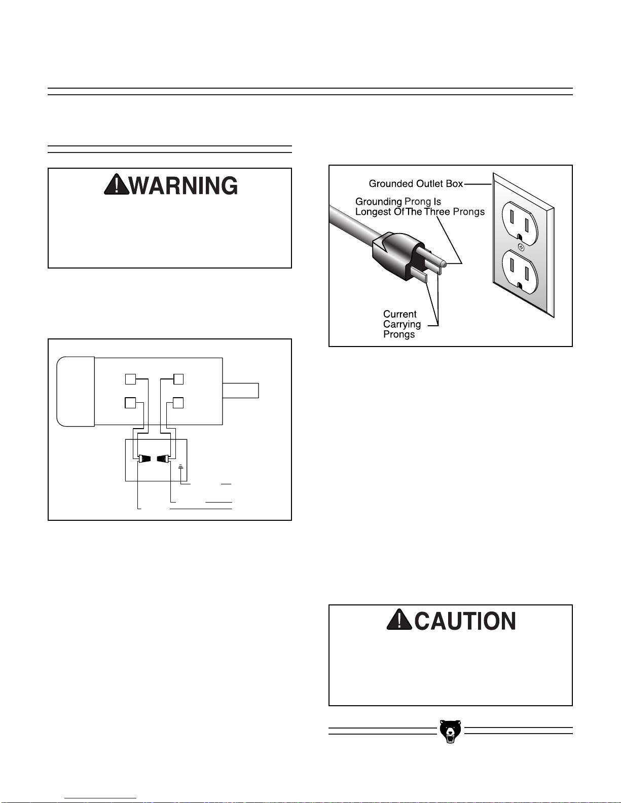
Figure 2. Typical type 5-15 plug and receptacle.
Figure 1. G0534/G0535 110V Wiring Diagram.
Serious personal injury could occur if you
connect your machine to the power source
before you have completed the set up
process. DO NOT connect the machine to
the power source until instructed to do so.
Wiring
Both Models G0534 and G0535 are prewired for
110V operation (see
Figure 1).
110V Operation
SECTION 3: CIRCUIT REQUIREMENTS
Your Shop Circuit Capacity
Always check to see if your circuit is capable of
handling the amperage draw from your machine,
as well as any other machines that could be operating on the same circuit. If you are unsure, consult a qualified electrician.
Grounding
In the event of an electrical short, grounding
reduces the risk of electric shock by providing a
path of least resistance to disperse electric current. This tool is equipped with a power cord that
has a plug with an equipment-grounding prong.
The outlet must be properly installed and grounded in accordance with all local codes and ordinances.
Plug Type
Both Models G0534 and G0535 are supplied with
a 5-15 plug, similar to
Figure 2.
Amperage Draw
The machines draw the following amps:
G0534 ....................................................10 Amps
G0535 ....................................................14 Amps
Circuit Breaker Requirements
Install your machine on a dedicated circuit to
reduce the possibility of tripping the circuit breaker. If the circuit breaker frequently trips, have the
circuit inspected by a qualified electrician. Never
use a larger circuit breaker than stated below, or
you will increase the risk of fire.
Circuit Breaker ............................15 Amp, 1 Pole
110 VOLT
MOTOR WIRES
3 2
1
Black
4
Green
White
GROUND
110 VOLT
POWER SUPPLY
FROM SWITCH
Page 9
G0534/G0535 Downdraft Tables -7-
A fire may occur if your particular electrical
configuration does not comply with local
and state codes. The best way to ensure
compliance is to check with your local
municipality or a licensed electrician.
Your Shop Circuit Capacity
Always check to see if your circuit is capable of
handling the amperage draw from your machine,
as well as any other machines that could be operating on the same circuit. If you are unsure, consult a qualified electrician.
Grounding
In the event of an electrical short, grounding
reduces the risk of electric shock by providing a
path of least resistance to disperse electric current. This tool is equipped with a power cord that
has a plug with an equipment-grounding prong.
The outlet must be properly installed and grounded in accordance with all local codes and ordinances.
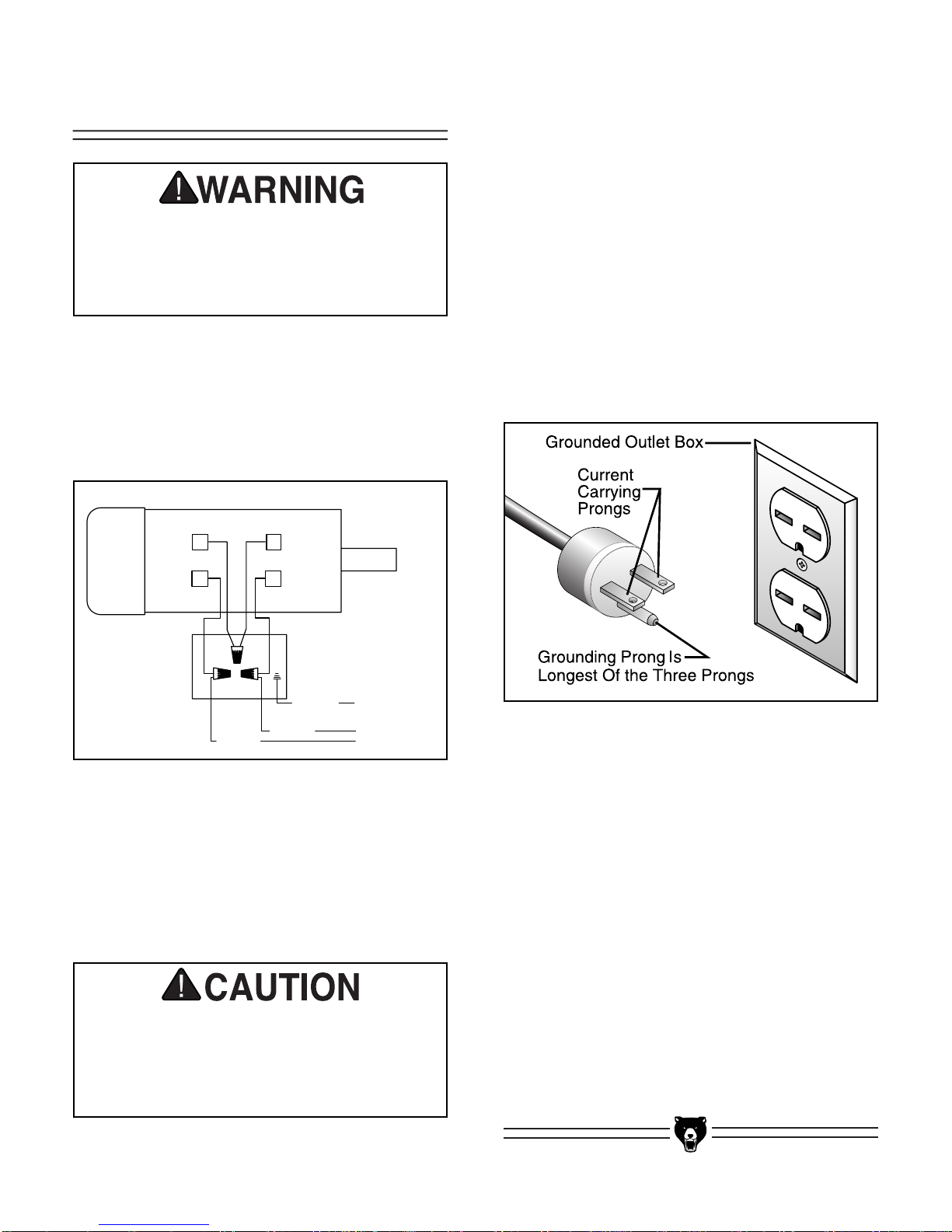
Figure 4. Typical type 6-15 plug
and receptacle.
Serious personal injury could occur if you
connect your machine to the power source
before you have completed the setup
process. DO NOT connect the machine to
the power source until instructed to do so.
Wiring
The Model G0534/G0535 is prewired for 110V
operation, but can be rewired to 220V. To rewire
for single-phase 220V, the plugs must be
changed and the motor must be rewired. When
rewiring, refer to the wiring diagram in
Figure 3.
220V Operation
Figure 3. G0534/G0535 220V Wiring Diagram.
Circuit Breaker Requirements
Install your machine on a dedicated circuit to
reduce the possibility of overloading the circuit
and tripping the circuit breaker. If the circuit
breaker trips and the circuit is of the correct load
capacity, have the circuit inspected by a qualified
electrician. Never use a larger circuit breaker
than stated below, or you will increase the risk of
fire.
Circuit Breaker ............................10 Amp, 2 Pole
Plug Type
For 220V operation, this machine requires a
NEMA 6-15 plug and receptacle, as shown in
Figure 4.
Amperage Draw
The motor for your machine draws the following
amps at 220V:
G0534 ......................................................5 Amps
G0535 ......................................................7 Amps
220 VOLT
MOTOR WIRES
3 2
1
Black
4
Green
White
GROUND
220 VOLT
POWER SUPPLY
FROM SWITCH
Page 10

-8- G0534/G0535 Downdraft Tables
1. Sanding Table—Features both regular and
rubber inlet ports to provide great dust collection and a non-marring surface for delicate workpieces.
2. Filter Drawer—Slides out for easy clean-up
of collected dust.
3. ON/OFF Switch—Starts and stops the
motor.
Not a replacement for unplugging
machine during maintenance.
4. Stand Mounted Casters—Allow the user to
move the machine where best needed in the
shop, without having to purchase an additional mobile base.
5. Dust Curtains—Improve the dust collection,
especially when sanding long workpieces.
Figure 5. Main view of machine features.
3
4
5
2
1
Machine Features
SECTION 4: MACHINE FEATURES
Page 11

G0534/G0535 Downdraft Tables -9-
Your machine left our warehouse in a carefully
packed crate or box. If you discover the machine
is damaged after you have signed for delivery,
please immediately call Customer Service at
(570) 546-9663 for advice.
Save the containers and all packing materials for
possible inspection by the carrier or its agent.
Otherwise, filing a freight claim can be difficult.
When you are completely satisfied with the condition of the shipment, you should inventory the
equipment.
Wear safety glasses during the entire set up
process!
This machine presents
serious injury hazards
to untrained users. Read
through this entire manual to become familiar
with the controls and
operations BEFORE
starting the machine!
Inventory
Unpacking
SECTION 5: SET UP
Please refer to Figures 6–9 and the list in this
subsection to inventory your equipment. In the
event that any non-proprietary parts are missing
(e.g. nuts or washers), we would be glad to
replace them, or for the sake of expediency,
replacements can be obtained at your local hardware store.
Figure 7. Filter box walls, motor cabinet
feet/casters, and hardware bag.
B
F
E
A
C
G
D
A. Rear Filter Wall ..........................................1
B. Side Filter Walls..........................................2
C. Upper Front Filter Wall................................1
D. Lower Front Filter Wall................................1
E. Cabinet Feet ..............................................2
F. Casters........................................................2
G. Hardware Bag (Model G0534)
—Hex Bolts
1
⁄4"-20 x 5⁄8" ............................72
—Flat Washers
1
⁄4"..................................138
—Hex Nuts
1
⁄4"-20 ....................................66
—Flat Head Screws
1
⁄4"-20 x 7⁄8" ................6
G. Hardware Bag (Model G0535)
—Hex Bolts
1
⁄4"-20 x 5⁄8" ............................76
—Flat Washers
1
⁄4"..................................146
—Hex Nuts
1
⁄4"-20 ....................................70
—Flat Head Screws
1
⁄4"-20 x 7⁄8" ................6
Page 12

-10- G0534/G0535 Downdraft Tables
I. Side Skewed Walls ....................................2
J. Brace (Model G0535 Only) ........................1
K. Front/Rear Skewed Walls ..........................2
L. Angle Brackets............................................4
M. Curtain Brackets..........................................2
Figure 8. Collection box components and cur-
tain brackets.
N. Rear Curtain w/Rod ....................................1
O. Side Curtains w/Rods..................................2
P. Curtain Frame ............................................1
Q. Table Top (G0534-not shown) ....................1
Q. Table Tops (G0535) ....................................1
R. Lock Handles w/Washers............................2
S. Filter Drawer................................................1
T. Switch Padlock (not shown) ......................1
Figure 9. Table tops, dust drawer, and curtain
components.
I
K
M
J
L
Q
N
P
S
R
O
H. Motor Cabinet
Figure 6. Motor Cabinet.
H
Page 13

G0534/G0535 Downdraft Tables -11-
Hardware Recognition Chart
Page 14

-12- G0534/G0535 Downdraft Tables
Figure 10. Minimum working clearances.
Floor Load
The Model G0534 weighs 106 lbs. and has a
base footprint of 13" x 13". The Model G0535
weighs 154 lbs. and has a base footprint of 19
1
⁄2"
x 19
1
⁄2".
Unsupervised children and
visitors could cause serious
personal injury to themselves with this machine.
Choose a site for placement
in your shop where you can
safely lock visitors and children away when you are not
with them.
Site Considerations
Working Clearances
Consider existing and anticipated needs, size of
material to be processed through each machine,
and space for auxiliary stands, work tables or
other machinery when establishing a location for
your machine. See
Figure 10 for the minimum
working clearances of the Model G0534/G0535.
G0535
32''
G0534
24''
36"
Front
24''
32''
36"
Page 15

G0534/G0535 Downdraft Tables -13-
Figure 11. Casters and feet installed on
motor cabinet.
Components and Hardware Needed: Qty
Motor Cabinet ....................................................1
Cabinet Feet ......................................................2
Casters ..............................................................2
Hex Bolts
1
⁄4"-20 x 5⁄8" ......................................16
Flat Washers
1
⁄4" ..............................................32
Hex Nuts
1
⁄4" ....................................................16
Tools Needed:
10mm Wrench or Socket....................................2
To mount the feet and casters:
1.
Lay the motor cabinet on its back.
2. Attach both cabinet feet to the bottom front of
the motor cabinet with 8 hex bolts, 16 flat
washers and 8 hex nuts.
3. Attach both casters to the bottom rear of the
motor cabinet with 8 hex bolts, 16 flat washers and 8 hex nuts. (See assembly in
Figure
11
.)
Filter Box
Figure 12. Rear filter wall installed on motor
cabinet.
Components and Hardware Needed: Qty
Rear Filter Wall ..................................................1
Side Filter Walls ................................................2
Lower Front Filter Wall ......................................1
Hex Bolts
1
⁄4"-20 x 5⁄8" ......................................16
Flat Washers
1
⁄4" ..............................................20
Hex Nuts
1
⁄4" ......................................................4
Tools Needed:
10mm Wrench or Socket....................................2
To assemble the filter box:
1.
Attach the rear filter wall to the base with 3
hex bolts and 3 flat washers (see
Figure 12).
4. Turn the motor cabinet to its upright position
on the feet and casters.
2. Attach both side filter walls to the base with 6
hex bolts and 6 flat washers.
Feet and Casters
Page 16

-14- G0534/G0535 Downdraft Tables
Collection Box
Figure 15. Side skewed wall partially attached
to the rear skewed wall with an angle bracket.
Components and Hardware Needed: Qty
Side Skewed Walls ............................................2
Brace (G0535 Only) ..........................................1
Front/Rear Skewed Walls (w/2 holes at top)......2
Upper Front Filter Wall ......................................1
Angle Brackets ..................................................4
Hex Bolts
1
⁄4"-20 x 5⁄8" ..................36 (G0535–40)
Flat Washers
1
⁄4" ..........................72 (G0535–80)
Hex Nuts
1
⁄4" ................................36 (G0535–40)
Tools Needed:
10mm Wrench or Socket....................................2
To assemble the collection box:
1.
Attach one of the side skewed walls to one of
the front/rear skewed walls by placing an
angle bracket over the holes and securing
the bottom two holes together with 4 hex
bolts, 8 flat washers, and 4 hex nuts, as
shown in
Figure 15. Note—DO NOT secure
the top holes of the angle brackets, because
they will be used later.
Figure 13. Side and rear filter walls installed on
motor cabinet.
Figure 14. Lower front filter wall secured to
motor cabinet and side walls.
3. Secure both lower corners of the side filter
walls to the rear filter wall with 2 hex bolts, 4
flat washers, and 2 hex nuts (
Figure 13).
4. Attach the lower front filter wall to the front of
the base and both side walls with 5 hex bolts,
7 flat washers, and 2 hex nuts (
Figure 14).
Top Holes
Unsecured
For Now
Page 17

G0534/G0535 Downdraft Tables -15-
Figure 17. Brace installed on Model G0535.
Figure 16. Partially assembled collection box—
all skewed walls and angle brackets installed.
3. If you have the Model G0535, attach the
brace to the front and rear walls with 4 hex
bolts, 8 flat washers, and 4 hex nuts (see
Figure 17). Note—If you have the Model
G0534, skip this step.
Figure 18. Collection box installed on motor
cabinet.
4. Attach the upper front filter wall to the front
skewed wall with 3 hex bolts, 6 flat washers,
and 3 hex nuts.
5. Place the collection box on top of the filter
box and align the holes.
6. Secure the collection box to the filter box with
13 hex bolts, 26 flat washers, and 13 hex
nuts, (see
Figure 18).
2. Using the other 3 angle brackets, attach the
remaining side skewed wall and front/rear
skewed wall with 12 hex bolts, 24 flat washers, and 12 hex nuts. Your completed
assembly should look like
Figure 16.
7. At the front corners of the collection box,
secure the top holes of the angle brackets
with 4 hex bolts, 8 flat washers, and 4 hex
nuts.
Page 18

-16- G0534/G0535 Downdraft Tables
Curtains
Figure 19. Curtain brackets installed over angle
brackets.
Components and Hardware Needed: Qty
Rear Curtain Rod ..............................................1
Side Curtain Rods ..............................................2
Curtain Brackets ................................................2
Curtain Frame ....................................................1
Lock Handles w/Washers ..................................2
Hex Bolts
1
⁄4"-20 x 5⁄8" ........................................4
Flat Washers
1
⁄4" ..............................................14
Hex Nuts
1
⁄4" ....................................................10
Flat Head Screws
1
⁄4"-20 x 7⁄8" ............................6
Tools Needed:
10mm Wrench or Socket....................................2
To assemble the curtains:
1.
At the rear corners of the collection box,
install both curtain brackets over the top
holes of the angle brackets with 4 hex bolts,
8 flat washers, 4 hex nuts (see
Figure 19).
Figure 20. Curtain frame installed on curtain
brackets.
2. Attach the curtain frame on the curtain brack-
ets with both lock handles w/washers
(
Figure 20).
Figure 21. Curtains installed on curtain frame.
3. Install the rear curtain rod to the curtain
frame with 2 flat head screws, 2 flat washers,
and 2 hex nuts.
4. Attach both side curtain rods to the curtain
frame with 4 flat head screws, 4 flat washers,
and 4 hex nuts (
Figure 21).
Page 19

G0534/G0535 Downdraft Tables -17-
Figure 22. Table top(s) installed on collection
box.
Components and Hardware Needed: Qty
Table Top (G0534) ............................................1
Table Tops (G0535) ..........................................2
Tools Needed:
None
To install the table top:
Fit the table top(s) into the top of the collection
box, so that your final assembly resembles
Figure 22.
Filter Drawer
Figure 23. Sliding filter drawer into filter box.
Components and Hardware Needed: Qty
Filter Drawer ......................................................1
Tools Needed:
None
To install the filter:
Slide the filter drawer into the filter box as shown
in
Figure 23.
NOTICE
The table top(s) are designed to fit tightly
into the collection box. Some assembly situations may require loosening the collection box fasteners to allow the table top(s)
to fit.
Table Top
Page 20

-18- G0534/G0535 Downdraft Tables
RESPIRATORY HAZARD!
Always wear a respirator
approved for wood dust
while emptying the dust
drawer on this machine.
Emptying Dust
The dust filter is a pleated-type filter and is permanently attached to the drawer. Frequently
monitor the dust build-up on the filter and empty
the dust drawer before it reaches the top edge of
the dust drawer shown in
Figure 25.
Figure 25. Top edge of dust drawer.
NOTICE
Any dust that rises over the top of the filter
drawer will be pulled into the motor compartment when the filter drawer is removed
for cleaning. For best results, empty the filter drawer BEFORE the dust levels build-up
this high.
Damage to your eyes, lungs, and ears could
result from using this machine without proper protective gear. Always wear safety glasses, a respirator, and hearing protection
when operating this machine.
Operations
The Model G0534/G0535 is operated by a push
button switch that is clearly labeled
START/STOP.
This switch can be locked out with the switch padlock, as shown in
Figure 24, when the downdraft
table is not in use.
SECTION 6: OPERATIONS
Figure 24. ON/OFF Switch locked out to
prevent accidental operation.
Page 21

G0534/G0535 Downdraft Tables -19-
The following pages contain the machine data
sheets, parts diagrams, parts lists, and the
Warranty/Return information for the Model
G0534/G0535.
If you need parts or help in assembling your
machine, or if you need operational information,
call the Grizzly Service Department. Trained service technicians will be glad to help you.
If you have any comments regarding this manual,
please write to Grizzly at the address below:
Grizzly Industrial, Inc.
C
/O Technical Documentation
P.O. Box 2069
Bellingham, WA 98227-2069
SECTION 7: REFERENCE INFO
We recommend you keep a copy of our current
catalog for complete information regarding
Grizzly's warranty and return policy. If you need
additional technical information relating to this
machine, or if you need general assistance or
replacement parts, please contact the Service
Department at the location listed below.
Grizzly Industrial, Inc.
1203 Lycoming Mall Circle
Muncy, PA 17756
Phone: (570) 546-9663
Fax: (800) 438-5901
E-Mail: techsupport@grizzly.com
Web Site: http://www.grizzly.com
.
Page 22

-20- G0534/G0535 Downdraft Tables
Design Type...................................................................................................... Floor Model
Overall Dimensions:
Table Height ..........................................................................................................411⁄2"
Table Size ................................................................................................24"D x 24"W
Shipping Weight (2 Boxes) ..............................................................................115 lbs.
Net Machine Weight..........................................................................................106 lbs.
Box 1 Size ..............................................................................25
1
⁄2"W x 181⁄2"D x 19"H
Box 2 Size ....................................................................................26"W x 26"D x 6
1
⁄2"H
Footprint ....................................................................................................13"W x 13"D
Construction:
Main Table ........................................................................................Pre-Formed Steel
Cabinet ..............................................................................................Pre-Formed Steel
Side Wall............................................................................................................Canvas
Filter........................................................................................................Pleated Fabric
Impeller ..........................................................................................................Aluminum
Bearings ................................................................Shielded & Permanently Lubricated
Capacities:
Air Delivery......................................................................................................600 CFM
Filter Area..................................................................................................15
1
⁄2" x 151⁄2"
Filtration Capacity ..........................................................................................5 Microns
Filter Efficiency ................................................................................................AFI 97%
Impeller Size ..............................................................................................................9"
Inlet Hole ....................................................................................................................8"
Rubber Inserts..................................................................................1
1
⁄8" Hole x 18 pcs
Motor:
Type ............................................................................TEFC Capacitor Start Induction
Horsepower ..........................................................................................................
1
⁄2 HP
Phase/Cycle ..................................................................................Single-Phase/60 Hz
Voltage ..........................................................................................................110/220V
Prewired Voltage ..................................................................................................110V
Amps ....................................................................................................................10/5A
RPM..............................................................................................................1725 RPM
Power Transfer ..........................................................................................Direct Drive
Power Switch..................................................................................On/Off Push Button
Specifications, while deemed accurate, are not guaranteed.
August, 2003
Customer Service #: (570) 546-9663 • To Order Call: (800) 523-4777 • Fax #: (800) 438-5901
MODEL G0534 DOWNDRAFT SANDING TABLE
MACHINE DATA
SHEET
Page 23

G0534/G0535 Downdraft Tables -21-
Design Type...................................................................................................... Floor Model
Overall Dimensions:
Table Height ..........................................................................................................441⁄2"
Table Size ..........................................................................................31
5
⁄8"D x 315⁄8"W
Shipping Weight (2 Boxes) ..............................................................................165 lbs.
Net Machine Weight..........................................................................................154 lbs.
Box 1 Size ....................................................................26
13
⁄32"W x 2213⁄16"D x 2123⁄32"H
Box 2 Size............................................................................34
1
⁄4"W x 2213⁄16"D x 61⁄2"H
Footprint ....................................................................................................17"W x 16"D
Construction:
Main Table ........................................................................................Pre-Formed Steel
Cabinet ..............................................................................................Pre-Formed Steel
Side Wall............................................................................................................Canvas
Filter........................................................................................................Pleated Fabric
Impeller ..........................................................................................................Aluminum
Bearings ................................................................Shielded & Permanently Lubricated
Capacities:
Air Delivery......................................................................................................780 CFM
Filter Area..................................................................................................19
1
⁄2" x 191⁄2"
Filtration Capacity ..........................................................................................5 Microns
Filter Efficiency ................................................................................................AFI 97%
Impeller Size..........................................................................................................10
1
⁄2"
Inlet Hole ....................................................................................................................9"
Rubber Inserts..................................................................................1
1
⁄8" Hole x 32 pcs
Motor:
Type ............................................................................TEFC Capacitor Start Induction
Horsepower............................................................................................................1 HP
Phase/Cycle ..................................................................................Single-Phase/60 Hz
Voltage ..........................................................................................................110/220V
Prewired Voltage ..................................................................................................110V
Amps ....................................................................................................................14/7A
RPM..............................................................................................................1725 RPM
Power Transfer ..........................................................................................Direct Drive
Power Switch..................................................................................On/Off Push Button
Specifications, while deemed accurate, are not guaranteed.
August, 2003
Customer Service #: (570) 546-9663 • To Order Call: (800) 523-4777 • Fax #: (800) 438-5901
MODEL G0535 DOWNDRAFT SANDING TABLE
MACHINE DATA
SHEET
Page 24

66
67
7
8
39
40
13
23
25
49
52
68
68-1
53
55
56
57
48
60
60-4
60-5
60-3
60-2
60-1
58
54
50
51
59
47
46
36
41
44
34
37
45
45-1
45-2
35
38
33
26
42
43
24
69
4
29
22
32
31
20
17
28
27
18
5
15
14
12
19
21
11
10
9
2
3
30
16
6
1
69
61
62
63
64
65
G0534
-22- G0534/G0535 Downdraft Tables
Page 25

1 P0534001 REAR CURTAIN
2 P0534002 FLAT HD SCR 1/4-20 X 7/8
3 PW06 FLAT WASHER 1/4
4 PN05 HEX NUT 1/4-20
5 P0534005 SIDE CURTAIN
6 P0534002 FLAT HD SCR 1/4-20 X 7/8
7 PW06 FLAT WASHER 1/4
8 PN05 HEX NUT 1/4-20
9 P0534009 CURTAIN FRAME
10 P0534010 LOCK HANDLE 5/16-18 X 1
11 PW07 FLAT WASHER 5/16
12 P0534012 TABLE BOARD
13 P0534013 RUBBER GROMMET
14 P0534014 FRONT/REAR SKEWED WALL
15 P0534015 ANGLE BRACKET
16 P0534016 CURTAIN BRACKET
17 PB02 HEX BOLT 1/4-20 X 5/8
18 PW06 FLAT WASHER 1/4
19 PW06 FLAT WASHER 1/4
20 PN05 HEX NUT 1/4-20
21 PB02 HEX BOLT 1/4-20 X 5/8
22 PW06 FLAT WASHER 1/4
23 PN05 HEX NUT 1/4-20
24 PW06 FLAT WASHER 1/4
25 PN05 HEX NUT 1/4-20
26 PW06 FLAT WASHER 1/4
27 PN05 HEX NUT 1/4-20
28 PW06 FLAT WASHER 1/4
29 PW06 FLAT WASHER 1/4
30 PB02 HEX BOLT 1/4-20 X 5/8
31 P0534031 REAR FILTER WALL
32 P0534032 SIDE FILTER WALL
33 PN05 HEX NUT 1/4-20
34 PW06 FLAT WASHER 1/4
35 PW06 FLAT WASHER 1/4
36 PB02 HEX BOLT 1/4-20 X 5/8
37 PW06 FLAT WASHER 1/4
38 PB02 HEX BOLT 1/4-20 X 5/8
39 P0534039 UPPER FRONT FILTER WALL
G0534
REF PART # DESCRIPTIONREF PART # DESCRIPTION
40 P0534040 LOWER FRONT FILTER WALL
41 PW06 FLAT WASHER 1/4
42 PB02 HEX BOLT 1/4-20 X 5/8
43 PS01 PHLP HD SCR 10-24 X 1/2
44 P0534044 SAFETY NET
45 P0534045 FILTER DRAWER
45-1 P0534045-1 DRAWER HANDLE
45-2 PHTEK10 TAP SCREW #8 X 5/8
46 P0534046 MOTOR CABINET
47 P0534047 CASTER
48 PN05 HEX NUT 1/4-20
49 PW06 FLAT WASHER 1/4
50 PW06 FLAT WASHER 1/4
51 PB02 HEX BOLT 1/4-20 X 5/8
52 P0534052 CABINET FOOT
53 P0534053 FOOT BOOT
54 P0534054 FAN
55 PB07 HEX BOLT 5/16-18 X 3/4
56 PW06 FLAT WASHER 1/4
57 P0534057 DEFLECTOR
58 PN05 HEX NUT 1/4-20
59 PW06 FLAT WASHER 1/4
60 P0534060 COMPLETE MOTOR 1/2 HP
60-1 P0534060-1 FAN COVER
60-2 P0534060-2 MOTOR FAN
60-3 P0534060-3 WIRING BOX
60-4 P0534060-4 S CAPACITOR 200M 125V SM
60-5 P0534060-5 R CAPACITOR 30M 250V SM
61 P0534061 G0534 MACHINE ID LABEL
62 P0534062 DOWNDRAFT WARNING LBL
63 PLABEL-12 READ MANUAL LABEL
64 PLABEL-14 ELECTRICITY LABEL
65 PLABEL-11 SAFETY GLASSES LABEL
66 PWRCRD110L 110V CORD W/5-15 PLUG
67 PWRCRD110S 110V MOTOR CORD
68 P0534068 PUSH BUTTON SWITCH
68-1 P0534068-1 SWITCH PADLOCK
69 P0534069 SIDE SKEWED WALL
G0534/G0535 Downdraft Tables -23-
Page 26

52
17
12
57
74
42
45
50
44
25
30
40
47
37
53
29
60
58
62
61
39
49
28
73
41
46
27
55
56
59
65
54
64
63
51
48
32
31
38
26
43
22
21
13
15
14
23
19
36
20
35
33
34
24
18
8
5
7
11
10
6
4
16
2
1
9
3
65-4
65-5
65-3
65-2
65-1
66
67
68
69
70
71
72
74-1
50-1
50-2
74
G0535
-24- G0534/G0535 Downdraft Tables
Page 27

G0535 Parts List
1 P0535001 REAR CURTAIN
2 P0534002 FLAT HD SCR 1/4-20 X 7/8
3 PW06 FLAT WASHER 1/4
4 PN05 HEX NUT 1/4-20
5 P0535005 SIDE CURTAIN
6 P0534002 FLAT HD SCR 1/4-20 X 7/8
7 PW06 FLAT WASHER 1/4
8 PN05 HEX NUT 1/4-20
9 P0535009 CURTAIN FRAME
10 P0534010 LOCK HANDLE 5/16-18 X 1
11 PW07 FLAT WASHER 5/16
12 P0535012 TABLE BOARD
13 P0534013 RUBBER GROMMET
14 P0535014 FRONT/REAR SKEWED WALL
15 P0535015 ANGLE BRACKET
16 P0535016 CURTAIN BRACKET
17 PB02 HEX BOLT 1/4-20 X 5/8
18 PW06 FLAT WASHER 1/4
19 PW06 FLAT WASHER 1/4
20 PN05 HEX NUT 1/4-20
21 PB02 HEX BOLT 1/4-20 X 5/8
22 PW06 FLAT WASHER 1/4
23 PB02 HEX BOLT 1/4-20 X 5/8
24 PW06 FLAT WASHER 1/4
25 PW06 FLAT WASHER 1/4
26 PN05 HEX NUT 1/4-20
27 PN05 HEX NUT 1/4-20
28 PW06 FLAT WASHER 1/4
29 PN05 HEX NUT 1/4-20
30 PW06 FLAT WASHER 1/4
31 PN05 HEX NUT 1/4-20
32 PW06 FLAT WASHER 1/4
33 PW06 FLAT WASHER 1/4
34 PB02 HEX BOLT 1/4-20 X 5/8
35 P0535035 REAR FILTER WALL
36 P0535036 SIDE FILTER WALL
37 PN05 HEX NUT 1/4-20
38 PW06 FLAT WASHER 1/4
39 PW06 FLAT WASHER 1/4
40 PB02 HEX BOLT 1/4-20 X 5/8
41 PW06 FLAT WASHER 1/4
REF PART # DESCRIPTIONREF PART # DESCRIPTION
42 PB02 HEX BOLT 1/4-20 X 5/8
43 P0535043 BRACE
44 P0535044 UPPER FRONT FILTER WALL
45 P0535045 LOWER FRONT FILTER WALL
46 PW06 FLAT WASHER 1/4
47 PB02 HEX BOLT 1/4-20 X 5/8
48 PS01 PHLP HD SCR 10-24 X 1/2
49 P0535049 SAFETY NET
50 P0535050 FILTER DRAWER
50-1 P0534045-1 DRAWER HANDLE
50-2 PHTEK10 TAP SCREW #8 X 5⁄8"
51 P0535051 MOTOR CABINET
52 P0535052 CASTER
53 PN05 HEX NUT 1/4-20
54 PW06 FLAT WASHER 1/4
55 PW06 FLAT WASHER 1/4
56 PB02 HEX BOLT 1/4-20 X 5/8
57 P0534057 CABINET FOOT
58 P0534058 FOOT BOOT
59 P0535059 FAN
60 PB07 HEX BOLT 5/16-18 X 3/4
61 PW07 FLAT WASHER 5/16
62 P0535062 DEFLECTOR
63 PN05 HEX NUT 1/4-20
64 PW06 FLAT WASHER 1/4
65 P0535065 MOTOR
65-1 P0535065-1 FAN COVER
65-2 P0535065-2 MOTOR FAN
65-3 P0535060-3 WIRING BOX
65-4 P0534060-4 S CAPACITOR 200M 125V SM
65-5 P0534060-5 R CAPACITOR 30M 250V SM
66 P0535066 G0535 MACHINE ID LABEL
67 P0534062 DOWNDRAFT WARNING LBL
68 PLABEL-12 READ MANUAL LABEL
69 PLABEL-14 ELECTRICITY LABEL
70 PLABEL-11 SAFETY GLASSES LABEL
71 PWRCRD110L 110V CORD W/5-15 PLUG
72 PWRCRD110S 110 MOTOR CORD
73 P0534068 SIDE SKEWED WALL
74 P0535074 PUSH BUTTON SWITCH
74-1 P0535074-1 SWITCH PADLOCK
G0534/G0535 Downdraft Tables -25-
Page 28

-26- G0534/G0535 Downdraft Tables
Grizzly Industrial, Inc. warrants every product it sells for a period of 1 year to the original purchaser from
the date of purchase. This warranty does not apply to defects due directly or indirectly to misuse, abuse,
negligence, accidents, repairs or alterations or lack of maintenance. This is Grizzly’s sole written warranty
and any and all warranties that may be implied by law, including any merchantability or fitness, for any particular purpose, are hereby limited to the duration of this written warranty. We do not warrant or represent
that the merchandise complies with the provisions of any law or acts unless the manufacturer so warrants.
In no event shall Grizzly’s liability under this warranty exceed the purchase price paid for the product and
any legal actions brought against Grizzly shall be tried in the State of Washington, County of Whatcom.
We shall in no event be liable for death, injuries to persons or property or for incidental, contingent, special, or consequential damages arising from the use of our products.
To take advantage of this warranty, contact us by mail or phone and give us all the details. We will then
issue you a “Return Number,’’ which must be clearly posted on the outside as well as the inside of the carton. We will not accept any item back without this number. Proof of purchase must accompany the merchandise.
The manufacturers reserve the right to change specifications at any time because they constantly strive to
achieve better quality equipment. We make every effort to ensure that our products meet high quality and
durability standards and we hope you never need to use this warranty.
Please feel free to write or call us if you have any questions about the machine or the manual.
Thank you again for your business and continued support. We hope to serve you again soon.
WARRANTY AND RETURNS
Page 29

CUT ALONG DOTTED LINE
___Other__________________________________________________
9. How many of your woodworking machines are Grizzly? _____________
10. Which benchtop tools do you own? Check all that apply.
___1" x 42" Belt Sander ___6" - 8" Grinder
___5" - 8" Drill Press ___Mini Lathe
___8" Table Saw ___10" - 12" Thickness Planer
___8" - 10" Bandsaw ___Scroll Saw
___Disc⁄Belt Sander ___Spindle⁄Belt Sander
___Mini Jointer
___Other__________________________________________________
11. How many of the machines checked above are Grizzly? ____________
12. Which portable⁄hand held power tools do you own? Check all that apply.
___________________________________________________________
___________________________________________________________
___________________________________________________________
13. What machines⁄supplies would you like Grizzly Industrial to carry?
___________________________________________________________
___________________________________________________________
___________________________________________________________
14. What new accessories would you like Grizzly Industrial to carry?
___Builders Hardware ___Hand Tools
___Fasteners ___Wood Components
___Other__________________________________________________
15. What other companies do you purchase your tools and supplies from?
__________________________________________________________
__________________________________________________________
16. Do you think your purchase represents good value?
___Yes ___No
17. Would you recommend Grizzly Industrial to a friend?
___Yes ___No
18. Would you allow us to use your name as a reference for Grizzly customers
in your area?
Note: We never use names more than three times.
___Yes ___No
19. Comments:__________________________________________________
__________________________________________________________
___________________________________________________________
___________________________________________________________
1. How did you learn about us?
___Advertisement ___Friend
___Catalog ___Card Deck
___World Wide Web
___Other__________________________________________________
2. Which of the following magazines do you subscribe to.
___American Woodworker ___Practical Homeowner
___Cabinetmaker ___Shop Notes
___Family Handyman ___Today’s Homeowner
___Fine Homebuilding ___WOOD
___Fine Woodworking ___Wooden Boat
___Home Handyman ___Woodshop News
___Journal of Light Construction ___Woodsmith
___Old House Journal ___Woodwork
___Popular Mechanics ___Woodworker
___Popular Science ___Woodworker’s Journal
___Popular Woodworking ___Workbench
___Other__________________________________________________
3. Which of the following woodworking⁄remodeling shows do you watch?
___Backyard America ___The New Yankee Workshop
___Home Time ___This Old House
___The American Woodworker ___Woodwright’s Shop
___Other__________________________________________________
4. What is your annual household income?
___$20,000-$29,999 ___$60,000-$69,999
___$30,000-$39,999 ___$70,000-$79,999
___$40,000-$49,999 ___$80,000-$89,999
___$50,000-$59,999 ___$90,000 +
5. What is your age group?
___20-29 ___50-59
___30-39 ___60-69
___40-49 ___70 +
6. How long have you been a woodworker?
___0 - 2 Years ___8 - 20 Years
___2 - 8 Years ___20+ Years
7. How would you rank your woodworking skills?
___Simple ___Advanced
___Intermediate ___Master Craftsman
8. What stationary woodworking tools do you own? Check all that apply.
___Air Compressor ___Panel Saw
___Band Saw ___Planer
___Drill Press ___Power Feeder
___Drum Sander ___Radial Arm Saw
___Dust Collector ___Shaper
___Horizontal Boring Machine ___Spindle Sander
___Jointer ___Table Saw
___Lathe ___Vacuum Veneer Press
___Mortiser ___Wide Belt Sander
Name ____________________________________________________________________________________
Street ____________________________________________________________________________________
City ______________________________________________________________State________Zip_________
Phone Number_______________________E-Mail_______________________FAX________________________
MODEL: ________________________ Serial #______________________ Order _______________________
The following information is given on a voluntary basis. It will be used for marketing purposes to help us develop better products and services. Of
course, all information is strictly confidential.
WARRANTY CARD
Page 30

TAPE ALONG EDGES--PLEASE DO NOT STAPLE
FOLD ALONG DOTTED LINE
FOLD ALONG DOTTED LINE
GRIZZLY INDUSTRIAL, INC.
P.O. BOX 2069
BELLINGHAM, WA 98227-2069
Place
Stamp
Here
Name_______________________________
Street_______________________________
City______________State______Zip______
Send a Grizzly Catalog to a friend:
Page 31

Page 32

Buy Direct and Save with Grizzly
®
– Trusted, Proven and a Great Value!
-OR-
• SECURE ORDERING
• ORDERS SHIPPED WITHIN 24 HOURS
• E-MAIL RESPONSE WITHIN ONE HOUR
Visit Our Website Today And Discover Why
Grizzly
®
Is The Industry Leader!
Call Today For A
FREE
Full Color Catalog
 Loading...