

Page 1

COPYRIGHT © SEPTEMBER, 2003 BY GRIZZLY INDUSTRIAL, INC.
WARNING: NO PORTION OF THIS MANUAL MAY BE REPRODUCED IN ANY SHAPE
OR FORM WITHOUT THE WRITTEN APPROVAL OF GRIZZLY INDUSTRIAL, INC.
PRINTED IN TAIWAN
ONLINE MANUAL DISCLAIMER
THE INFORMATION IN THIS MANUAL REPRESENTS THE CONFIGURATION OF THE MACHINE AS IT IS CURRENTLY BEING SHIPPED. THE MACHINE
CONFIGURATION CAN CHANGE AS PRODUCT IMPROVEMENTS ARE INCORPORATED. IF YOU OWN AN EARLIER VERSION OF THE MACHINE, THIS
MANUAL MAY NOT EXACTLY DEPICT YOUR MACHINE . CONTACT CUSTOMER SERVICE IF YOU HAVE ANY QUESTIONS ABOUT DIFFERENCES. PRE-
VIOUS VERSIONS ARE NOT AVAILABLE ONLINE.
OSCILLATING SPINDLE &
12" DISC SANDER
MODEL G0529
INSTRUCTION MANUAL
Page 2

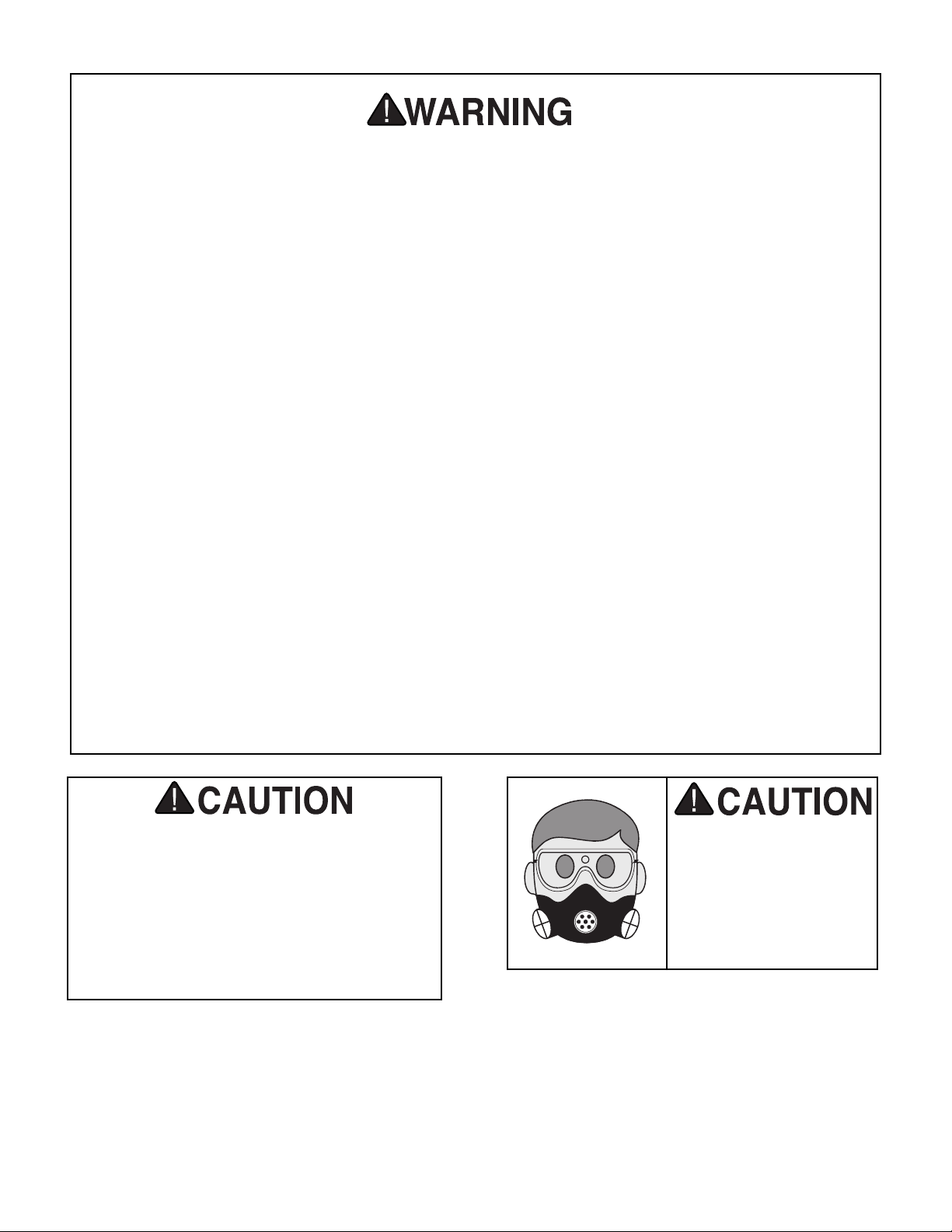
WARNING
Some dust created by power sanding, sawing,
grinding, drilling, and other construction activities contains chemicals known to the State of
California to cause cancer, birth defects or
other reproductive harm. Some examples of
these chemicals are:
• Lead from lead-based paints.
• Crystalline silica from bricks, cement,
and other masonry products.
• Arsenic and chromium from chemically
treated lumber.
Your risk from these exposures varies, depending on how often you do this type of work. To
reduce your exposure to these chemicals: work
in a well ventilated area, and work with
approved safety equipment, such as those dust
masks that are specially designed to filter out
microscopic particles.
Page 3

SECTION 1: SAFETY............................................................................................................................2
Safety Instructions For Power Tools ..............................................................................................2
SECTION 2: INTRODUCTION ..............................................................................................................5
SECTION 3: CIRCUIT REQUIREMENTS ............................................................................................6
110 Volt ..........................................................................................................................................6
Extension Cords..............................................................................................................................7
Grounding........................................................................................................................................7
SECTION 4: MACHINE FEATURES ....................................................................................................8
SECTION 5: SET UP ............................................................................................................................9
Unpacking ......................................................................................................................................9
Parts Inventory ................................................................................................................................9
Hardware Recognition Chart ........................................................................................................10
Clean Up ......................................................................................................................................11
Site Considerations ......................................................................................................................11
Cabinet Assembly ........................................................................................................................12
Beginning Assembly......................................................................................................................12
Mounting Sander ..........................................................................................................................13
Installing Spindle ..........................................................................................................................13
Table Inserts ................................................................................................................................14
Squaring Table..............................................................................................................................14
Squaring Disc Sander ..................................................................................................................15
Sanding Disc ................................................................................................................................16
Aligning Table ..............................................................................................................................16
Miter Gauge ..................................................................................................................................17
Dust Collection ..............................................................................................................................17
SECTION 6: OPERATIONS ................................................................................................................18
General..........................................................................................................................................18
Power Switch ................................................................................................................................18
Spindle Sanding ............................................................................................................................19
SECTION 7: MAINTENANCE ............................................................................................................21
Maintenance Log ..........................................................................................................................22
SECTION 8: REFERENCE INFO ........................................................................................................23
General..........................................................................................................................................23
Aftermarket ..................................................................................................................................23
Parts Diagrams & Lists ................................................................................................................25
Troubleshooting ............................................................................................................................29
Warranty & Returns ......................................................................................................................30
Table of Contents
Page 4

-2-
G0529 Oscillating Spindle & Disc Sander
5. KEEP CHILDREN AND VISITORS
AWAY. All children and visitors should be
kept at a safe distance from work area.
6. MAKE WORKSHOP CHILD PROOF with
padlocks, master switches, or by removing
starter keys.
7. NEVER FORCE TOOL. It will do the job
better and safer at the rate for which it was
designed.
8. USE RIGHT TOOL. DO NOT force tool or
attachment to do a job for which it was not
designed.
1. KEEP GUARDS IN PLACE and in working
order.
2. REMOVE ADJUSTING KEYS AND
WRENCHES. Form a habit of checking to
see that keys and adjusting wrenches are
removed from tool before turning on.
3. KEEP WORK AREA CLEAN. Cluttered
areas and benches invite accidents.
4. NEVER USE IN DANGEROUS ENVIRONMENT. DO NOT use power tools in damp
or wet locations, or where any flammable
or noxious fumes may exist. Keep work
area well lighted.
For Your Own Safety Read Instruction
Manual Before Operating This Equipment
Indicates an imminently hazardous situation which, if not avoided,
WILL result in death or serious injury.
Indicates a potentially hazardous situation which, if not avoided,
COULD
result in death or serious injury.
Indicates a potentially hazardous situation which, if not avoided,
MAY
result in minor or moderate injury. It may also be used to alert
against unsafe practices.
This symbol is used to alert the user to useful information about
proper operation of the equipment.
The purpose of safety symbols is to attract your attention to possible hazardous conditions.
This manual uses a series of symbols and signal words which are intended to convey the level
of importance of the safety messages. The progression of symbols is described below.
Remember that safety messages by themselves do not eliminate danger and are not a substitute for proper accident prevention measures.
NOTICE
Safety Instructions For Power Tools
SECTION 1: SAFETY
Page 5

G0529 Oscillating Spindle & Disc Sander -3-
9. USE PROPER EXTENSION CORD. Make
sure your extension cord is in good condition. Conductor size should be in accordance with the chart below. The amperage
rating should be listed on the motor or tool
nameplate. An undersized cord will cause
a drop in line voltage resulting in loss of
power and overheating. Your extension
cord must also contain a ground wire and
plug pin. Always repair or replace extension cords if they become damaged.
Minimum Gauge for Extension Cords
10. WEAR PROPER APPAREL. DO NOT
wear loose clothing, gloves, neckties,
rings, bracelets, or other jewelry which may
get caught in moving parts. Non-slip
footwear is recommended. Wear protective
hair covering to contain long hair.
11. ALWAYS USE SAFETY GLASSES. Also
use face or dust mask if cutting operation is
dusty. Everyday eyeglasses only have impact
resistant lenses, they are NOT safety glasses.
12. ALLERGIES: Certain wood may cause an
allergic reaction in people or animals, especially when exposed to fine dust. Make sure you
know what type of wood dust you will be
exposed to and wear proper respirators.
13. DO NOT OVER-REACH. Keep proper
footing and balance at all times.
14. MAINTAIN TOOLS WITH CARE. Keep
tools sharp and clean for best and safest
performance. Follow instructions for lubricating and changing accessories.
LENGTH
AMP RATING 25ft 50ft 100ft
0-6 16 16 16
7-10 16 16 14
11-12 16 16 14
13-16 14 12 12
17-20 12 12 10
21-30 10 10 No
Safety Instructions For Power Tools
15. USE RECOMMENDED ACCESSORIES.
Consult the owner’s manual for recommended accessories. The use of improper
accessories may cause risk of injury.
16. REDUCE THE RISK OF UNINTENTIONAL STARTING. On machines with magnet-
ic contact starting switches there is a risk of
starting if the machine is bumped or jarred.
Always disconnect from power source
before adjusting or servicing. Make sure
switch is in OFF position before reconnecting.
17. CHECK DAMAGED PARTS. Before further use of the tool, a guard or other part
that is damaged should be carefully
checked to determine that it will operate
properly and perform its intended function.
Check for alignment of moving parts, binding of moving parts, breakage of parts,
mounting, and any other conditions that
may affect its operation. A guard or other
part that is damaged should be properly
repaired or replaced.
18. NEVER LEAVE TOOL RUNNING UNATTENDED. TURN POWER OFF. DO NOT
leave tool until it comes to a complete stop.
19. NEVER OPERATE A MACHINE WHEN
TIRED, OR UNDER THE INFLUENCE OF
DRUGS OR ALCOHOL. Full mental alert-
ness is required at all times when running a
machine.
20. NEVER ALLOW UNSUPERVISED OR
UNTRAINED PERSONNEL TO OPERATE THE MACHINE. Make sure any
instructions you give in regards to machine
operation are approved, correct, safe, and
clearly understood.
21. IF AT ANY TIME YOU ARE EXPERIENCING DIFFICULTIES performing the intend-
ed operation, stop using the machine! Then
contact our service department or ask a
qualified expert how the operation should
be performed.
Page 6
-4-
G0529 Oscillating Spindle & Disc Sander
No list of safety guidelines can be complete. Every shop environment is different.
Always consider safety first, as it applies to
your individual working conditions. Use
this and other machinery with caution and
respect. Failure to follow guidelines could
result in serious personal injury, damage to
equipment or poor work results.
Additional Safety Instructions For The
Oscillating Spindle & Disc Sander
• READ THIS MANUAL. This manual con-
tains proper operating instructions for this
machine.
• DO NOT jam the workpiece against the
sanding surfaces. Firmly grasp the workpiece in both hands and ease it against the
spindle/disc using light pressure.
• DO NOT wear loose clothing while operat-
ing this machine. Roll up or button sleeves
at the cuff.
• DO NOT place hands near, or in contact
with, sanding surfaces during operation.
• GRIP THE WORKPIECE WITH BOTH
HANDS.
• PERFORM machine inspections and
maintenance service promptly when called
for.
• NEVER leave the machine running unattended.
• REPLACE sanding discs and sleeves
when they become worn.
• NEVER sand more than one piece of stock
at a time.
• ALWAYS inspect board stock for nails,
staples, knots, and other imperfections
that could be dislodged and thrown from
the machine during sanding operations.
• NEVER operate the sander without an
adequate dust collection system in place
and running.
• NEVER sand tapered or pointed stock with
the point facing the feed direction.
• DISCONNECT THE MACHINE FROM
THE POWER SOURCE before changing
the sanding disc or sleeve.
• TEST RUN THE MACHINE before starting
any work.
Always wear a respirator when operating the
Model G0529. Using this
machine produces sawdust which may cause
allergic reactions or respiratory problems.
Page 7
G0529 Oscillating Spindle & Disc Sander -5-
We are proud to offer the Model G0529
Oscillating Vertical Spindle Sander & 12" Disc
Sander. This machine is part of a growing Grizzly
family of fine woodworking machinery. When
used according to the guidelines set forth in this
manual, you can expect years of trouble-free,
enjoyable operation and proof of Grizzly’s commitment to customer satisfaction.
We are pleased to provide this manual with the
Model G0529. It was written to guide you through
assembly, review safety considerations, and
cover general operating procedures. It represents
our effort to produce the best documentation possible.
If you have any comments regarding this manual,
please write to us at the address below:
Grizzly Industrial, Inc.
C
/O Technical Documentation
P.O. Box 2069
Bellingham, WA 98227-2069
Most importantly, we stand behind our machines.
If you have any service questions or parts
requests, please call or write us at the location
listed below.
Grizzly Industrial, Inc.
1203 Lycoming Mall Circle
Muncy, PA 17756
Phone: (570) 546-9663
Fax: (800) 438-5901
E-Mail: techsupport@grizzly.com
Web Site: http://www.grizzly.com
The specifications, drawings, and photographs
illustrated in this manual represent the Model
G0529 as supplied when the manual was prepared. However, owing to Grizzly’s policy of continuous improvement, changes may be made at
any time with no obligation on the part of Grizzly.
For your convenience, we always keep current
Grizzly manuals available on our website at
www.grizzly.com
. Any updates to your machine
will be reflected in these manuals as soon as they
are complete. Visit our site often to check for the
latest updates to this manual!
SECTION 2: INTRODUCTION
Lack of familiarity with
this manual could
cause serious personal injury. Become
familiar with the contents of this manual,
including all the safety
warnings.
Page 8
-6-
G0529 Oscillating Spindle & Disc Sander
Amperage Draw
The Model G0529 1 HP motor is wired to operate
at 110V and will draw the following load:
Motor Load............................................10 Amps
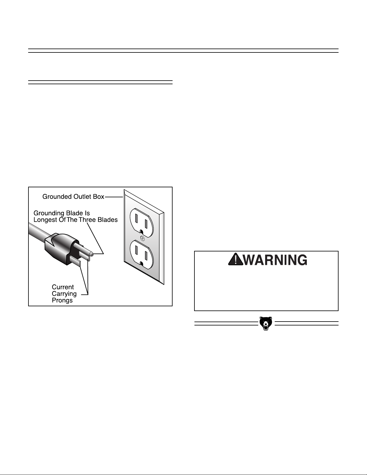
Plug Type
The Model G0529 is supplied with a NEMA 5-15
plug. DO NOT modify the plug or power cord in
any way. See Figure 1 for a NEMA 5-15 plug and
grounded outlet.
Circuit Breaker Requirements
We recommend that the circuit you use your
machine on should be dedicated. Use the following guidelines when choosing a circuit breaker for
your machine (circuit breakers rated any higher
are not adequate to protect the circuit):
Recommended Circuit Breaker ..............15 Amp
Your Circuit Capacity
Always check to see if the wires in your circuit are
capable of handling the amperage load from your
machine. If you are unsure, consult a qualified
electrician.
If you operate this machine on any circuit that is
already close to its capacity, it might blow a fuse
or trip a circuit breaker. However, if an unusual
load does not exist and a power failure still
occurs, contact a qualified electrician or our
Service Department at (570) 546-9663.
Serious personal injury could occur if you
connect your machine to the power source
before you have completed the assembly
process. DO NOT connect the machine to
the power source until instructed to do so.
Figure 1. NEMA 5-15 plug and
grounded outlet.
110 Volt
SECTION 3: CIRCUIT REQUIREMENTS
Page 9

G0529 Oscillating Spindle & Disc Sander -7-
Grounding
In the event of an electrical short, grounding
reduces the risk of electric shock by providing a
path of least resistance to disperse electric current. This tool is equipped with a power cord that
has an equipment-grounding prong. The outlet
must be properly installed and grounded in accordance with all local codes and ordinances.
110V Operation
If you find it necessary to use an extension cord
at 110V:
• Make sure the cord is rated Standard Service
(grade S) or better.
• The extension cord must also contain a
ground wire and plug pin.
• Use at least a 16 gauge cord if the cord is 50
feet long or less.
•DONOT use a cord longer that 100 feet!
Extension Cords
This machine must have a ground prong in
the plug to help ensure that it is grounded.
DO NOT remove ground prong from plug to
fit into a two-pronged outlet! If the plug will
not fit the outlet, have the proper outlet
installed by a qualified electrician.
Electrocution or a fire
can result if the machine
is not grounded correctly. Make sure all electrical circuits are grounded. DO NOT use the
machine if it is not
grounded.
No single list of electrical guidelines can
be comprehensive for all shop environments. Operating this machinery may
require additional electrical upgrades specific to your machine and shop environment. It is your responsibility to make sure
your electrical systems comply with all
local electrical codes and ordinances.
NOTICE
The wire on the power cord with green or
green and yellow striped insulation is the
grounding conductor.
Page 10
-8-
G0529 Oscillating Spindle & Disc Sander
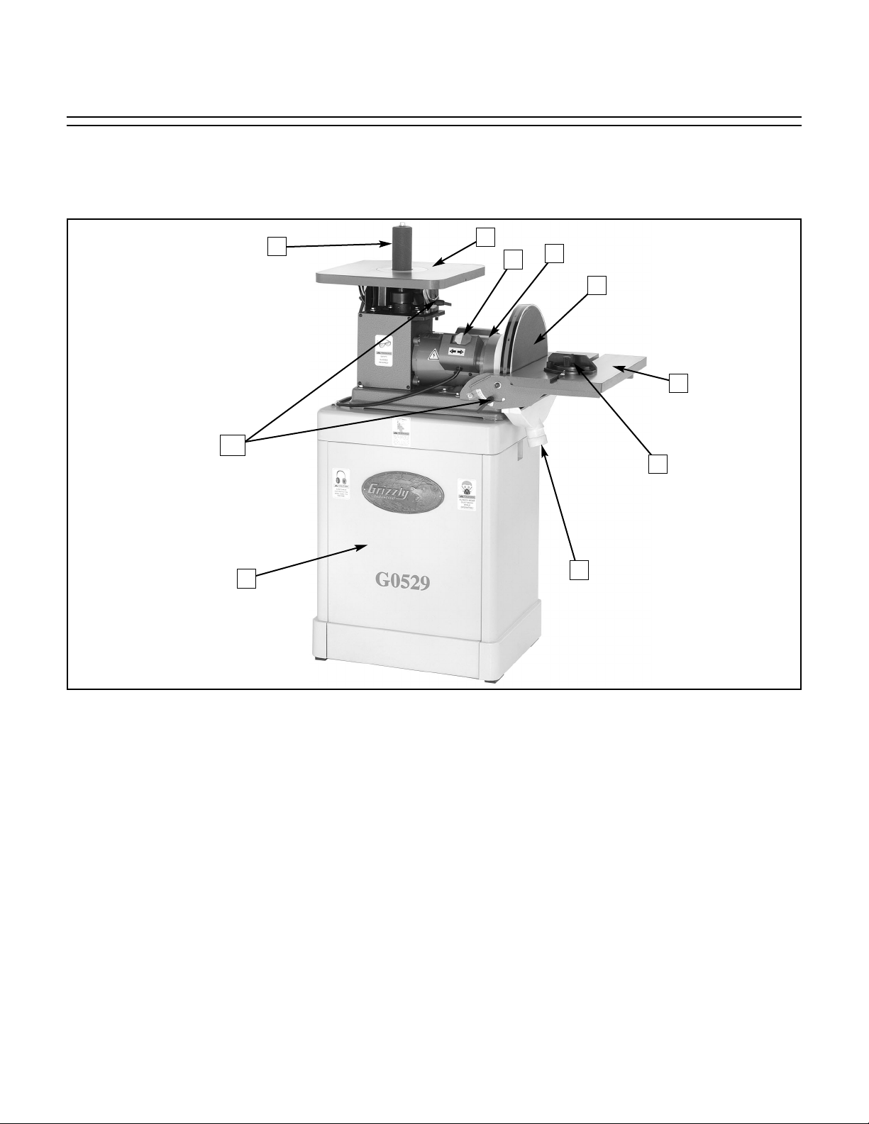
1. Sanding Spindle
2. Cast Iron Spindle Sanding Table
3. Power Switch
4. Motor
5. Sanding Disc
6. Cast Iron Disc Sanding Table
7. Miter Gauge
8. Dust Ports (Spindle Port Not Shown)
9. Cabinet
10. Graduated Scales
SECTION 4: MACHINE FEATURES
Figure 2. Machine Features.
An important part of safety is knowing your machine and its components. Take the time to familiarize
yourself with the features of your new G0529 Oscillating Spindle & 12" Disc Sander. They will be frequently mentioned throughout the instructions in this manual.
1
10
9
8
7
6
5
4
3
2
Page 11
G0529 Oscillating Spindle & Disc Sander -9-
The Model G0529 Oscillating Spindle & 12" Disc
Sander was carefully packed at the factory. If you
discover the machine is damaged after you have
signed for delivery, and the truck and driver are
gone, you will need to file a freight claim with the
carrier. Save the containers and all packing materials for possible inspection by the carrier or its
agent. Without the packing materials, filing a
freight claim can be difficult. If you need assistance determining whether you need to file a
freight claim, or with the procedure to file one,
please contact our Customer Service.
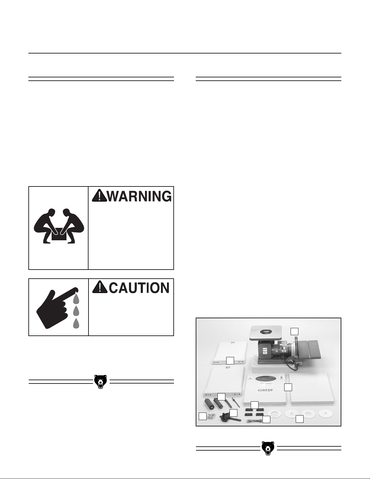
When you are completely satisfied with the condition of your shipment, you should inventory its
parts.
DESCRIPTION Qty
A. Sander unit . . . . . . . . . . . . . . . . . . . . . . .1
B. Left and Right Side Panels . . . . . . . . . . .2
C. Front and Pear Panels . . . . . . . . . . . . . .2
D. Miter Gauge Assembly . . . . . . . . . . . . . .1
E. Spindle Assemblies
• 2" . . . . . . . . . . . . . . . . . . . . . . . . . . . .1
• 1
1
⁄2
" . . . . . . . . . . . . . . . . . . . . . . . . . . .1
•
5
⁄8
" . . . . . . . . . . . . . . . . . . . . . . . . . . . .1
•
1
⁄4 " . . . . . . . . . . . . . . . . . . . . . . . . . . . .1
F. Table Inserts
• Oval Table Insert 2" . . . . . . . . . . . . . . .1
• Table Insert 2" . . . . . . . . . . . . . . . . . . .1
• Oval Table Insert
3
⁄4" . . . . . . . . . . . . . . .1
• Table Insert
3
⁄4" . . . . . . . . . . . . . . . . . . .1
G. Rubber Floor Pads
• Flat Head Screws
5
⁄16"-18 x 3⁄4" . . . . . . .4
• Washers
5
⁄16" . . . . . . . . . . . . . . . . . . . . .4
• Nuts
5
⁄16" . . . . . . . . . . . . . . . . . . . . . . .4
H. Wrench Hardware Bag
• Open End Wrench 17mm . . . . . . . . . . .2
• Open End Wrench 12mm . . . . . . . . . . .1
I. Hardware Bag
• Hex Bolts
5
⁄16"-18 x 3⁄4" . . . . . . . . . . . . . .8
• Hex Nuts
5
⁄16"-18 . . . . . . . . . . . . . . . . .10
• Lock Washers
5
⁄
16" . . . . . . . . . . . . . . .10
• Washers
5
⁄16" . . . . . . . . . . . . . . . . . . . .18
• Hex Bolts
5
⁄16"-18 x 11⁄4" . . . . . . . . . . . . .2
• Hex Key 6mm . . . . . . . . . . . . . . . . . . . .1
Figure 2. G0529 inventory.
The Model G0529
weighs 143 lbs.
Personal injury could
occur if the machine is
moved without additional assistance. Seek help
when moving or lifting
the machine.
Sharp edges on metal
parts may cause personal injury. Examine the
edges of all metal parts
before handling.
B
E
C
A
F
D
H
G
I
Parts InventoryUnpacking
SECTION 5: SET UP
Page 12

-10-
G0529 Oscillating Spindle & Disc Sander
Hardware Recognition Chart
USE THIS CHART TO MATCH UP
HARDWARE DURING THE ASSEMBLY
PROCESS!
#
10
1
⁄4''
Thumb
Screw
Phillips
Head
5
⁄16''
3
⁄8''
7
Cap
Screw
⁄16''
Screw
Carriage
Bolt
Hex
1
⁄2''
Setscrew
5
⁄8''
Head
Bolt
Lock
Washer
MEASURE BOLT DIAMETER BY PLACING INSIDE CIRCLE
4mm
6mm
5mm
10mm
8mm
15mm
20mm
Washer
1
⁄4''
3
⁄8''
1
⁄2''
5
⁄8''
25mm
10mm
30mm
35mm
40mm
45mm
12mm
LINES ARE 1MM APART
50mm
55mm
60mm
⁄16'' INCH APART
1
65mm
16mm
70mm
75mm
LINES ARE
Lock
Nut
Countersunk
Phillips
Head
Screw
Phillips
Head
Hex
Bolt
Hex
Nut
5
⁄16''
7
⁄16''
9
⁄16''
3
⁄4''
7
⁄8''
1''
1
1
⁄4''
1
⁄2''
1
3
⁄4''
1
2
1
⁄4''
2
1
⁄2''
2
3
⁄4''
2
3
D
I
A
R
H
S
W
M
E
T
⁄8''
9
R
D
⁄16''
1
⁄2''
E
R
I
A
M
E
T
E
R
D
I
A
M
E
T
E
R
5
R
E
E
Flange
Bolt
Wing
Nut
Slotted
Screw
Phillips
Button
Head
Screw
S
A
W
E
H
H
S
A
W
A
Head
Sheet
Metal
Screw
D
I
A
R
12mm
D
I
A
D
I
A
M
R
M
E
M
E
T
E
R
D
I
A
R
M
E
H
E
S
T
E
A
R
W
4mm
E
T
E
R
D
I
A
R
M
E
E
H
T
S
E
A
R
W
6mm
T
E
A
S
S
W
H
A
S
A
E
H
E
W
E
H
W
R
10mm
R
8mm
WASHERS ARE MEASURED BY THE INSIDE DIAMETER
D
I
A
R
W
H
S
A
M
E
T
7
⁄16''
E
R
D
I
R
A
M
E
W
H
S
E
3
T
⁄8''
E
R
D
I
A
R
M
E
E
5
T
⁄16''
E
A
R
W
D
I
A
R
M
E
H
E
1
S
⁄4''
T
A
E
R
W
D
I
R
A
E
M
H
E
S
T
A
E
R
W
#
10
E
H
S
A
Page 13

G0529 Oscillating Spindle & Disc Sander -11-
Site Considerations
Clean Up
The unpainted surfaces are coated with a waxy
oil to protect them from corrosion during shipment. Remove this protective coating with a solvent cleaner or citrus-based degreaser such as
Grizzly’s G7895 Degreaser. To clean thoroughly,
some parts may need to be removed. For opti-
mum performance from your machine, make
sure you clean all moving parts or sliding
contact surfaces that are coated. Avoid chlo-
rine-based solvents as they may damage painted
surfaces should they come in contact.
Gasoline and petroleum
products have low flash
points and could explode
if used to clean machinery. DO NOT use gasoline or petroleum products to clean the machinery.
Smoking near solvents
could ignite an explosion
or fire and cause serious
injury. DO NOT smoke
while using solvents.
Lack of ventilation while
using solvents could
cause serious personal
health risks, fire, or
environmental hazards.
Always work in a well
ventilated area to prevent the accumulation
of dangerous fumes.
Supply the work area
with a constant source
of fresh air.
Unsupervised children
and visitors inside your
shop could receive serious personal injury.
Ensure child and visitor
safety by keeping all
entrances to the shop
locked at all times. DO
NOT allow unsupervised
children or visitors in the
shop at any time.
Weight Load
The Model G0529 weighs 143 lbs. and has a
21
1
/4" X 161/2" footprint. Most shop floors should
be sufficient to carry the weight of the machine.
Reinforce the floor if you question its ability to
support the weight.
Working Clearance
Working clearances can be thought of as the distances between machines and obstacles that
allow safe operation of every machine without
limitation. Consider existing and anticipated
machine needs, size of material to be processed
through each machine, and space for auxiliary
stands or work tables. Also consider the relative
position of each machine to one another for efficient material handling.
Lighting And Outlets Lighting should be bright
enough to eliminate shadow and prevent eye
strain. Electrical circuits should be dedicated or
large enough to handle the amperage draw.
Outlets should be located near each machine so
power or extension cords are clear of high-traffic
areas. Observe local electrical codes for proper
installation of new lighting, outlets, or circuits.
Page 14

-12-
G0529 Oscillating Spindle & Disc Sander
Beginning Assembly
Loose hair and clothing
could get caught in
machinery and cause
serious personal injury.
Keep loose clothing
rolled up and long hair
tied up and away from
machinery.
Serious personal injury
could occur if you connect your machine to the
power source before you
have completed the
assembly process. DO
NOT connect the
machine to the power
source until instructed to
do so.
Sharp edges on metal
parts may cause personal injury. Examine the
edges of all metal parts
before handling.
This section will cover the basic assembly and
adjustment instructions needed to begin operation. Complete the assembly in the order provided in this manual and then read the remaining
portion of the manual before attempting any type
of operation.
Your safety is important! Please follow the
warnings below during this entire section:
Cabinet Assembly
Figure 3. Assembled panels.
Figure 4. Installing rubber feet.
The Model G0529 Sander mounts on a sturdy
cabinet stand.
To assemble the cabinet stand:
1. Connect all four panels together with the
5
⁄16"
-18 x
3
/4" hex bolts, lock washers, washers
and hex nuts (Figure 3).
2. Using the
5
⁄16" flat head screws, 5⁄16" washers
and nuts, install the four rubber feet as
shown in Figure 4.
!
Page 15

G0529 Oscillating Spindle & Disc Sander -13-
Installing SpindleMounting Sander
To install the spindle onto the sander:
1. Disconnect the machine from the power
supply.
2. Select the proper diameter of spindle sleeve.
The Model G5029 comes with the following
four sizes of spindle sleeves:
•
1
⁄4"
•
5
⁄8"
• 1
1
⁄2"
•2"
3. Make sure the tapered end of the spindle
sleeve is clean before installing it into the
sander spindle.
4. Use the supplied open end wrenches to
secure the spindle as shown in Figure 6.
Note—Do not over tighten the spindle
sleeve, it could make removal difficult.
Figure 6. Installing spindle.
!
Figure 5. Cabinet hole location.
When the cabinet has been completed, it is time
to place the sander unit on top of the cabinet
stand.
To mount the sander to the top of the cabinet
stand:
1. With the help of an assistant, place the
sander on the cabinet stand.
The Model G0529
weighs 143 lbs.
Personal injury could
occur if the machine is
moved without additional assistance. Seek help
when moving or lifting
the machine.
2. Align the holes on the rim of the cabinet
sides with the threaded holes in the rim of the
sander.
3. Secure the cabinet and the sander together
with the
5
⁄16"-18 x 11⁄4" hex bolts, 5⁄16" lock
washers, and
5
⁄16" flat washers combination
as shown in Figure 5.
!
Page 16

-14-
G0529 Oscillating Spindle & Disc Sander
To square the sanding tables:
1. Disconnect the machine from the power sup-
ply.
2. Set the table at 90˚ as shown in Figure 8.
3. Place a machinist square on the table and
against the sanding spindle to verify the table
is 90˚ from the edge of the sanding sleeve as
shown in Figure 9.
4. Adjust the pointer to 90˚.
Figure 8. Setting the table scale at 90˚.
Figure 9. Squaring the table and spindle.
Figure 7. Installing table inserts.
Squaring TableTable Inserts
The table inserts minimize the gap between the
working surface edge and the spindle. It is important to use the proper table insert according to the
diameter spindle you are using.
The Model G5029 comes with the following four
table inserts:
• 2"
• 1"
• 2" elliptical
• 1" elliptical
Select the table insert that comes closest the
spindle sleeve diameter without touching it. The
elliptical inserts are used when sanding with the
table tilted.
Place the table insert into the table hole as shown
in Figure 7.
!!!
Pointer
Page 17

G0529 Oscillating Spindle & Disc Sander -15-
Figure 10. Squaring the sanding table.
5. If the table is not 90˚ from the spindle, adjust
the table stop bolt to allow the table to move
more as shown in Figure 10.
Figure 11. Squaring the sanding table.
Squaring Disc
Sander
The sanding tables for the spindle sander and the
disc sander have tilting capabilities from 0˚ to 45˚.
To tilt the sanding table:
1. Disconnect the machine from the power sup-
ply.
2. Using a machinist square, set one edge on
the table surface and the other against the
face of the sanding disc as shown in Figure
11. Note—This can be done with the sand-
paper installed, although it is somewhat easier to measure if the disc does not have the
sandpaper disc installed.
3. Loosen the lock lever and adjust the table
angle until it is perfectly perpendicular and
flush with both edges of the machinist
square.
4. Tighten the lock lever while holding the table
perpendicular.
5. Adjust the scale pointer to read 0˚ when the
table has been properly adjusted.
!
6. Tighten the table stop bolt against the under-
side of the table when the table is set at 90˚.
Page 18

-16-
G0529 Oscillating Spindle & Disc Sander
The table must be aligned to the face of the sanding disc so that the sandpaper does not rub
against the table.
To align the table:
1. Loosen the bolts that secure the table to the
table support bracket as shown in Figure 13.
2. Align the table so that there is a
1
⁄16'' gap
between the 12" disc and the table.
3. Tighten the bolts loosened in step 1.
4. Spin the disc by hand to check if the sand-
paper is touching the table. Note—DO NOT
turn the disc sander on at this point.
5. Repeat steps 1-3 if the sandpaper touches
table at any point in the rotation.
Aligning Table
Figure 13. Loosening table bolts.
Figure 12. Installing sanding disc.
Sanding Disc
Installation
The disc sander requires 12" sanding discs with
hook and loop backing.
To install a new sanding disc on the 12" disc
sanding surface:
1. Disconnect the machine from the power sup-
ply.
2. Remove the disc sanding table.
3. Remove the old sanding disc.
4. Install the new sanding disc as shown in
Figure 12.
!
!
Page 19

G0529 Oscillating Spindle & Disc Sander -17-
Figure 15. Dust ports.
Dust CollectionMiter Gauge
There are two 2" dust collection ports for the
sander that should be connected to a dust collector. The ports are located under the sanding
tables as shown in Figure 15.
Figure 14. Squaring miter gauge to disc.
The miter gauge needs to be adjusted perpendicular to the face of the wheel when it is mounted in
the table slot.
To adjust miter gauge:
1. Use a machinist square with one edge
against the face of the miter gauge and the
other against the disc face as shown in
Figure 14.
2" Dust Ports
!
2. Loosen the lock knob on the miter gauge to
adjust it flush with the edge of the square.
3. Tighten the lock knob, and verify the setting.
Note—Sometimes the tightening procedure
can affect the adjustment.
4. Loosen the setscrew that secures the angle
pointer and adjust the pointer to the 0˚ mark
on the scale.
5. Retighten the setscrew that secures the
angle pointer.
To connect your machine to a dust collection
system:
1. Use a 2" diameter hose to connect a dust
collection system to your dust ports.
2. Start the dust collection system before oper-
ating the sander.
Page 20

G0529 Oscillating Spindle & Disc Sander-18-
Damage to your eyes, lungs, and ears
could result from failure to wear safety
glasses, a respirator, and hearing protection while sanding with this machine.
Loose hair and clothing
could get caught in
machinery and cause
serious personal injury.
Keep loose clothing
rolled up and long hair
tied up and away from
machinery.
This section covers basic disc sanding operations. Please read the remaining portion of the
manual before attempting any type of operation.
Your safety is important! Please follow the
warnings below during this entire section:
Operating this equipment has the potential
to propel debris into the air which can
cause eye injury. Always wear safety glasses or goggles when operating equipment.
Everyday glasses or reading glasses only
have impact resistant lenses, they are not
safety glasses. Be certain the safety glasses you wear meet the appropriate standards of the American National Standards
Institute (ANSI).
The Model G0529 sander is equipped with a paddle-type power switch with a safety key.
To operate the power switch:
1. Insert the safety locking key shown in Figure
16.
Figure 16. On/Off Switch.
2. Lift the switch to start and press to stop the
motor.
3. Remove the locking key when the machine is
not in use and store the key in a safe place.
Make sure the power switch is in the OFF
position before connecting the sander to the
power source. Serious personal injury could
occur if you connect your machine to the
power source with the power switch ON.
Power Switch
General
SECTION 6: OPERATIONS
Page 21

G0529 Oscillating Spindle & Disc Sander -19-
Spindle Sanding
Never use the Model G0529 for applications other than those for which it was
made. DO NOT overload the machine or
use excess force when sanding. Severe
personal injury, damage to the machine,
or damage to your workpiece could
occur.
The oscillating spindle sander on the Model
G0529 produces an extremely fine sanding finish
on edges or contours. The oscillation of the spindle disperses the material contact throughout the
sanding sleeve to prevent burning.
To perform spindle sanding operations:
1. Check to make sure that the table insert has
been installed correctly and the spindle is
secured tightly.
2. Set the angle of the table relative to the
sanding sleeve. The angle can be set with
the angle gauge on the spindle sander table
or with a protractor for greater accuracy.
Note—The spindle sander table can be posi-
tioned from 0˚ to 45˚, relative to the plane of
the sanding surface.
3. Make sure that the appropriate spindle has
been selected for the intended operation and
that it is installed properly.
4. Connect the sander to a dust collection system.
5. Turn the power switch ON to start the spindle
sander and begin sanding as shown in
Figure 17. DO NOT FORCE THE WORKPIECE AGAINST THE SANDING SLEEVE.
Figure 17. Spindle sanding.
Page 22

-20-
G0529 Oscillating Spindle & Disc Sander
Disc Sanding
To perform disc sanding operations:
1. Set the angle of the table relative to the
sanding disc. The angle can be set with the
angle gauge on the disc sander or with a protractor for greater accuracy.
Note—The disc table can be positioned from
0˚ to 45˚, relative to the plane of the sanding
surface.
2. Once the desired table angle has been set,
move the table towards the sanding disc to
decrease the gap between the table and the
disc. The gap should be
1
⁄16".
3. To sand straight edges, firmly hold the side
of workpiece against the miter gauge (set at
0˚), with the other surface against the face of
the disc (Figure 18).
Note—For sanding curves or irregular
shapes, remove the miter gauge from the
disc table. Always keep the workpiece on the
side of the wheel that is rotating down toward
the table. This will keep the workpiece from
flying out of your hands from the rotational
forces.
Miter Sanding
The most efficient way to get a perfect miter is to
cut the workpiece slightly long and sand it to the
desired dimension. Miter sanding can be done
easily with the miter gauge:
To perform miter sanding operations:
1. Loosen the knob on the miter gauge, adjust
the angle to the desired point, and tighten the
knob.
2. Slide the miter gauge into its slot and use it
to hold your workpiece in position (Figure
19). Note—The miter gauge can be used in
either direction in the slot to achieve the
proper relation of the workpiece to the disc.
Figure 18. Disc sanding with table tilted.
Figure 19. Disc sanding with miter.
Page 23

G0529 Oscillating Spindle & Disc Sander -21-
Serious personal injury
could occur if you connect your machine to the
power source during the
maintenance process.
DO NOT connect the
machine to the power
source while performing
any maintenance on this
machine.
Your safety is important! Please follow the
warnings below during this entire section:
Check for the following conditions before you
use the sander:
• Loose table bolts.
• Worn or damaged sanding discs or
sleeves.
• Worn or damaged wires.
• Any other condition that could hamper
the safe operation of this machine.
Perform the following tasks at the scheduled
time intervals:
After Each Use
• Wipe off the sawdust build-up from
the table surface.
• Turn off power switch and remove the
switch key.
• Check for spindle straightness.
Weekly
• Wipe a lubricant such as SLIPIT
®
onto
the table.
• All the bearings are permanently lubricated and require no further lubrication
Long-Term Storage
• Keep unpainted surfaces rust free
with products such as Boeshield
®
T-9.
ScheduleMaintenance Safety
SECTION 7: MAINTENANCE
!
Page 24

-22-
G0529 Oscillating Spindle & Disc Sander
Maintenance Performed
Approximate Hours Of Use
Maintenance Log
Date
Page 25

G0529 Oscillating Spindle & Disc Sander -23-
This section contains the following subsections
for the Model G0529: aftermarket accessories,
data sheets, parts diagrams and list, troubleshooting, and warranty/return information.
If you need parts or help in assembling your
machine, or if you need operational information,
call the service department at (570) 546-9663.
Trained service technicians will be glad to help
you.
If you have any comments regarding this manual,
please write to Grizzly at the address below:
Grizzly Industrial, Inc.
C
/O Technical Documentation
P.O. Box 2069
Bellingham, WA 98227-2069
We recommend you keep a copy of our current
catalog for complete information regarding
Grizzly's warranty and return policy. If you need
additional technical information relating to this
machine, or if you need general assistance or
replacement parts, please contact the Service
Department at the location listed below.
Grizzly Industrial, Inc.
1203 Lycoming Mall Circle
Muncy, PA 17756
Phone: (570) 546-9663
Fax: (800) 438-5901
E-Mail: techsupport@grizzly.com
Web Site: http://www.grizzly.com.
To order replacement sanding discs or spindle
sleeves, call our customer service line 24 hours
a day at 1-800-523-4777 or visit our website at
www.grizzly.com.
PRO-STICK
®
Abrasive Surface Cleaners
Extend the life of your sanding discs and sleeves!
Size
Model
11⁄2" X 11⁄2" X 81⁄2" ....................................G1511
2" X 2" X 12" ............................................G1512
Figure 15.
PRO-STICK
®
abrasive cleaners.
Aftermarket
Accessories
General
SECTION 8: REFERENCE INFO
Page 26

-24-
G0529 Oscillating Spindle & Disc Sander
Customer Service #: (570) 546-9663 • To Order Call: (800) 523-4777 • Fax #: (800) 438-5901
MACHINE DATA
SHEET
Design Type ......................................................................................................Floor Model
Overall Dimensions:
Height ....................................................................................................................47"H
Height (Spindle Table to Floor)..............................................................................42"H
Height (Disc Table to Floor) ..................................................................................33"H
Height (Cabinet)..................................................................................................27
1
⁄2"H
Width ....................................................................................................................32"W
Depth (Length)...................................................................................................... 18"D
Table (Disc)............................................................................................17
3
⁄4"W x 10"D
Table (Spindle) ..........................................................................................14
1
⁄2" x 141⁄2"
Motor Shaft Size ................................................................................................ 15mm
Footprint ........................................................................................21
1
⁄4"W x 161⁄2"D
Box Size ....................................................................................34"W x 30
1
⁄2"D x 21"H
Weight (net ...................................................................................................... 166 lbs.
Weight (shipping) ............................................................................................ 180 lbs.
Construction:
Table ................................................................................ Precision Ground Cast Iron
Disc ..............................................................................Computer Balanced Aluminum
Base ..................................................................................................Pre-Formed Steel
Cabinet ..............................................................................................Pre-Formed Steel
Miter Gauge ................................................................................Plastic With Steel Bar
Bearings ............................................Sealed & Permanently Lubricated Ball Bearings
Motor:
Type ............................................................................TEFC Capacitor Start Induction
Horsepower............................................................................................................1 HP
Phase Type ⁄ Voltage ....................................................................Single Phase ⁄ 110V
Amps ......................................................................................................................10A
Cycle & RPM ....................................................................................60 Hz /1725 RPM
Switch................................................................................On/Off Toggle w/Safety Key
Power Transfer ................................................................................Direct / Gear Drive
Features:
Spindle Sizes..............................................................................
1
⁄4", 5⁄8", 11⁄2", 2" x 51⁄2"
Spindle Stroke ............................................................................................................1"
Spindle Oscillation..............................................................................60 Strokes / Min.
Spindle Speed ..............................................................................................1725 RPM
Disc Speed ..................................................................................................1725 RPM
Disc Size ..................................................................................................................12"
Dust Port ....................................................................................................................2"
Specifications, while deemed accurate, are not guaranteed.
G0529 OSCILLATING SPINDLE & 12" DISC SANDER
Page 27

G0529 Oscillating Spindle & Disc Sander -25-
Parts Diagrams & Lists
66
117
42
33
104
28
109
116
107
108
10
71
41
115
12
65
64
63
52
46
44
61
110
3
30
88
45
31
78
86
67
27
114
29
114
107
108
11
101
102
104
33
103
34
91
36
100
99
112
133
136
39
113
97
38
96
98
94
37
35
135
132
95
9
131
36
93
92
91
89
5
108
84
106
138
8
107
118
117
22
25
26
141
23
77
24
75
23-4
23-1
108
116
76
23-2
121
20
23-3
15
104
21
19
48
121
14
22
16
18
17
109
139
124
100
2
119
107
108
7
90
40
87
43
45
85
60
6
4
13
116
Page 28

-26-
G0529 Oscillating Spindle & Disc Sander
Parts Diagrams & Lists
108
106
108
82
116
125
80
83
108
82
83
126
125
108
143
82
116
81
140
142
137
126
80
81
Page 29

G0529 Oscillating Spindle & Disc Sander -27-
2 P0529002 BASE UPPER
3 P0529003 FRAME
4 P0529004 SPINDLE
5 P0529005 HELICAL BEVEL GEAR
6 P0529006 PU HELICAL BEVEL GEAR
7 P0529007 RIGHT OIL BOX
8 P0529008 LEFT OIL BOX
9 P0529009 CONNECTION ROD
10 P0529010 RIGHT BRACKET
11 P0529011 LEFT BRACKET
12 P0529012 WORKING TABLE
13 PW02 FLAT WASHER
3
⁄8
14 P0529014 WORKING TABLE
15 P0529015 FRONT GRADUATED SCALE
16 P0529016 REAR GRADUATED SCALE
17 P0529017 DUST HOOD
18 P0529018 DISC GUARD
19 P0529019 DISC
20 P0529020 FRONT BRACKET
21 P0529021 REAR BRACKET
22 P0529022 HAND KNOB
23 P0529023 MOTOR 1 HP
23-1 P0529023-1 MOTOR FAN
23-2 P0529023-2 FAN COVER
23-3 P0529023-3 CAPACITOR COVER
23-4 P0529023-4 CAPACITOR
24 P0529024 SWITCH BOX
25 PSW07 PADDLE SWITCH 110 V
26 P0529026 INDICATOR
27 P0529027 RIGHT GRADUATED SCALE
28 P0529028 LEFT GRADUATED SCALE
29 P0529029 DUST HOOD
30 P0529030 SPINDLE
31 P0529031 GUIDE ROD
32 PSS11 SETSCREW
1
⁄4-20 X 1⁄4
33 P0529033 HANDLE
34 P0529034 WORM GEAR
35 P0529035 CAM
36 P0529036 COPPER SLEEVE
37 P6001 BALL BEARING 6001ZZ
38 P0529038 WORM GEAR SHAFT
39 P0529039 WORM GEAR HOUSING
40 P0529040 CONNECTION PIECE
41 P0529041 SIDE COVER
42 P0529042 FRONT & REAR COVER
43 P0529043 SPACER
44 P0529044 ARBOR
5
⁄8
45 PK36M KEY 5 X 5 X 50
46 P0529046 RUBBER PAD 2
47 P0529047 RUBBER PAD 1- 1⁄2
48 PSB05 CAP SCREW 1⁄4-20 X 3⁄4
50 P0529050 ARBOR 1⁄4
52 P0529052 SANDING CLOTH 2
53 P0529053 SANDING CLOTH
1
⁄4
55 P0529055 SANDING CLOTH 5⁄8
56 P0529056 SANDING CLOTH 1-1⁄2
59 P0529059 HOLDING DOWN PLATE 1⁄4
60 PB32M HEX BOLT M10-1.5 X 25
61 P0529061 LOWER PRESSURE PLATE 2
62 P0529062 UPPER PRESSURE PLATE 1-
1
⁄2
63 P0529063 UPPER PRESSURE PLATE 2
64 PW07 FLAT WASHER
5
⁄16
65 PN35 HEX NUT 5⁄16-18 (LH)
66 P0529066 2 TABLE INSERT (ELLIPTICAL)
67 P0529067 2 TABLE INSERT (ROUND)
68 P0529068
3
⁄4 TABLE INSERT (ROUND)
69 P0529069
3
⁄4 TABLE INSERT (ELLIPTICAL)
71 PRP61M ROLL PIN 3 X 12
72 PWR1417 WRENCH 17MM
73 PWR1214 WRENCH 12MM
75 P0529075 STRAIN RELIEF BUSHING
76 PWRCRD110L POWER CORD
77 P0529077 GRADUATED SCALE
78 P0529078 POSITIONING ROD
79 P0529079 SPINDLE WASHER
80 P0529080 PAD
81 PFH14 FLAT HD SCR
5
⁄
16-18 X
3
⁄
4
82 PLW01 LOCK WASHER 5⁄16
83 PN02 HEX NUT 5⁄16-18
84 PK20M KEY 5 X 5 X15
85 PK42M KEY 6 X 6 X 30
86 PN08 HEX NUT
3
⁄8-16
87 P6006 BALL BEARING 6006ZZ
88 PR19M ` EXT RETAINING RING 28MM
89 P6804 BALL BEARING 6804ZZ
90 PR55M INT RETAINING RING 60MM
91 PLN02M LOCK NUT M5-.8
92 PW02M WASHER 5MM
93 P0529093 CONNECTION SHAFT
94 PR03M EXT RETAINING RING 12MM
95 PR20M INT RETAINING RING 28MM
96 PK47M KEY 4 X 4 X15
97 P0529097 REAR OIL COVER
98 PS18 PHLP HD SCR 10-24 X
1
⁄4
99 PLW03M LOCK WASHER 6MM
100 PSB28M CAP SCREW M6-1 X 15
101 P0529101 POINTER
103 PS22M PHLP HD SCR M5-.8 X 25
REF PART # DESCRIPTION REF PART # DESCRIPTION
Page 30

-28-
G0529 Oscillating Spindle & Disc Sander
124 P0529124 STAND TOP
125 P0529125 RIGHT AND LEFT PANEL
126 P0529126 FRONT/REAR PANEL
127 P6003 BALL BEARING 6003ZZ
129 P0529129 SANDING PAPER 100 GRIT
131 P0529131 MITER GAUGE BODY
132 P0529132 MITER GAUGE BAR
133 PS06 PHLP HD SCR 10-24 X
3
⁄8
135 P0529135 MITER GAUGE KNOB
136 P0529136 POINTER
137 PLABEL-12 WARNING LABEL-READ MANUAL
138 PLABEL-14 WARNING LABEL-ELECTRICITY
139 PLABEL-11 WARNING LABEL-GLASSES
140 PLABEL-32 WARNING LABEL-DUST MASK
141 PLABEL-26 WARNING LABEL-DISCONNECT
142 P0529142 WARNING LABEL-ID LABEL
143 G8588 GRIZZLY LOGO
104 PW06 FLAT WASHER 1⁄4
106 PSB07 CAP SCREW
5
⁄16-18 X 3⁄4
107 PLW01 LOCK WASHER 5⁄
16
108 PW07 FLAT WASHER 5⁄16
109 PSB33M CAP SCREW M5-.8 X 12
110 P0529110 COVER
112 PSS08M SET SCREW M4-.7 X 5
113 PEC02M E-CLIP 4MM
114 PB07M HEX BOLT M8-1.25 X 25
115 PSS02M SETSCREW M6-1 X 5
116 PB03 HEX BOLT
5
⁄
16-18 X 1
117 PS06 PHLP HD SCR 10-24 X
3
⁄8
118 PN01M HEX NUT M6-1
119 PB04 HEX BOLT
5
⁄
16-18 X 3
120 PLN03 LOCK NUT
5
⁄16-18
121 PB19 HEX BOLT
1
⁄
4-20 X
1
⁄
2
123 P0529123 CARTON
REF PART # DESCRIPTION REF PART # DESCRIPTION
Page 31

G0529 Oscillating Spindle & Disc Sander -29-
Troubleshooting
TROUBLE
Grains easily rub off the
sleeve or disc .
Deep sanding grooves or
scars in workpiece.
Sanding surface clogs
quickly or burns.
Glazed sanding surfaces.
Motor will not start.
Motor will not start; fuses or
circuit breakers blow.
Motor overheats.
Motor stalls (resulting in
blown fuses or tripped
circuit).
Burn marks on workpiece.
Machine slows when
operating.
Machine vibrates
excessively.
Workpiece frequently gets
pulled out of your hand.
CAUSE
1. Sanding sleeve/disc has been stored in
an incorrect environment.
2. Sanding sleeve/disc has been smashed
or folded.
1. Sanding sleeve/disc grit is too coarse
for the desired finish.
2. Workpiece sanded across the grain.
3. Too much sanding force on workpiece.
4. Workpiece held still against the
sleeve/disc.
1. Too much pressure against sleeve/disc.
2. Sanding softwood.
1. Sanding wet stock.
2. Sanding stock with high residue.
1. Low voltage.
2. Open circuit in motor or loose connections.
1. Short circuit in line cord or plug.
2. Short circuit in motor or loose connections.
3. Incorrect fuses or circuit breakers in
power line.
1. Motor overloaded.
2. Incorrect usage of machine.
3. Air circulation through the motor
restricted.
1. Short circuit in motor or loose connections.
2. Low voltage.
3. Incorrect fuses or circuit breakers in
power line.
4. Motor overloaded.
1. Using too fine of sanding grit.
2. Using too much pressure.
3. Work held still for too long.
1. Applying too much pressure to workpiece.
2. Undersized circuit or using ext cord.
1. Stand not stable on floor.
2. Incorrect motor mounting.
3. Incorrect sanding sleeve tension.
4. Weak or broken tension spring.
5. Idler roller is too loose.
6. Broken/defective sanding sleeve/disc.
1. Not supporting the workpiece against
the stop.
2. Starting the workpiece on a leading corner.
CORRECTION
1. Store sanding sleeve/disc away from extremely hot or dry temperatures.
2. Store sanding sleeve/disc flat not bent or folded.
1. Use a finer grit sanding sleeve/disc.
2. Sand with the grain.
3. Reduce pressure on workpiece while sanding.
4. Keep workpiece moving while sanding on the sleeve/disc.
1. Reduce pressure on workpiece while sanding.
2. Use different stock. Or, accept the characteristics of the stock
and plan on cleaning/replacing sleeves frequently.
1. Dry stock properly before sanding.
2. Use different stock. Or, accept the characteristics of the stock
and plan on cleaning/replacing sleeves/discs frequently.
1. Check power line for proper voltage.
2. Inspect all lead connections on motor for loose or open connections.
1. Inspect cord or plug for damaged insulation and shorted wires.
2. Inspect all connections on motor for loose or shorted terminals
or worn insulation.
3. Install correct fuses or circuit breakers.
1. Reduce load on motor.
2. Reduce the applied load on the machine.
3. Clean out motor to provide normal air circulation.
1. Inspect connections on motor for loose or shorted terminals or
worn insulation.
2 Correct the low voltage conditions.
3. Install correct fuses or circuit breakers.
4. Reduce load on motor.
1. Use a coarser grit sanding sleeve/disc.
2. Reduce pressure on workpiece while sanding.
3. Do not keep workpiece in one place for too long.
1. Sand with less pressure—let the movement of the sleeve/disc
do the work.
2. Make sure circuit wires are proper gauge & don’t use ext cords!
1. Secure stand to floor, reposition to level surface, or shim stand.
2. Check/adjust motor mounting.
3. Make sure tension lever is in tensioning position. Follow sleeve
tensioning instructions in this manual.
4. Replace spring.
5. Adjust idler roller.
6. Replace sanding sleeve/disc.
1. Use back stop to support workpiece.
2. Start workpiece on a trailing corner.
Page 32

-30-
G0529 Oscillating Spindle & Disc Sander
Grizzly Industrial, Inc. warrants every product it sells for a period of 1 year to the original purchaser from
the date of purchase. This warranty does not apply to defects due directly or indirectly to misuse, abuse,
negligence, accidents, repairs or alterations or lack of maintenance. This is Grizzly’s sole written warranty
and any and all warranties that may be implied by law, including any merchantability or fitness, for any particular purpose, are hereby limited to the duration of this written warranty. We do not warrant or represent
that the merchandise complies with the provisions of any law or acts unless the manufacturer so warrants.
In no event shall Grizzly’s liability under this warranty exceed the purchase price paid for the product and
any legal actions brought against Grizzly shall be tried in the State of Washington, County of Whatcom.
We shall in no event be liable for death, injuries to persons or property or for incidental, contingent, special, or consequential damages arising from the use of our products.
To take advantage of this warranty, contact us by mail or phone and give us all the details. We will then
issue you a “Return Number,’’ which must be clearly posted on the outside as well as the inside of the carton. We will not accept any item back without this number. Proof of purchase must accompany the merchandise.
The manufacturers reserve the right to change specifications at any time because they constantly strive to
achieve better quality equipment. We make every effort to ensure that our products meet high quality and
durability standards and we hope you never need to use this warranty.
Please feel free to write or call us if you have any questions about the machine or the manual.
Thank you again for your business and continued support. We hope to serve you again soon.
Warranty & Returns
Page 33

CUT ALONG DOTTED LINE
9. How many of your woodworking machines are Grizzly? _____________
10. Which benchtop tools do you own? Check all that apply.
___1" x 42" Belt Sander ___6" - 8" Grinder
___5" - 8" Drill Press ___Mini Lathe
___8" Table Saw ___10" - 12" Thickness Planer
___8" - 10" Bandsaw ___Scroll Saw
___Disc/Belt Sander ___Spindle/Belt Sander
___Mini Jointer
___Other__________________________________________________
11. How many of the machines checked above are Grizzly? ____________
12. Which portable/hand held power tools do you own? Check all that apply.
___Belt Sander ___Orbital Sander
___Biscuit Joiner ___Palm Sander
___Circular Saw ___Portable Planer
___Detail Sander ___Saber Saw
___Drill/Driver ___Reciprocating Saw
___Miter Saw ___Router
___Other__________________________________________________
13. What machines/supplies would you like Grizzly Industrial to carry?
__________________________________________________________
__________________________________________________________
14. What new accessories would you like Grizzly Industrial to carry?
__________________________________________________________
__________________________________________________________
15. What other companies do you purchase your tools and supplies from?
__________________________________________________________
__________________________________________________________
16. Do you think your purchase represents good value?
___Yes ___No
17. Would you recommend Grizzly Industrial to a friend?
___Yes ___No
18. Would you allow us to use your name as a reference for Grizzly customers
in your area? Note: We never use names more than three times.
___Yes ___No
19. Comments:_________________________________________________
__________________________________________________________
__________________________________________________________
__________________________________________________________
__________________________________________________________
1. How did you learn about us?
___Advertisement ___Friend
___Catalog ___Card Deck
___World Wide Web
___Other__________________________________________________
2. Which of the following magazines do you subscribe to.
___American Woodworker ___Practical Homeowner
___Cabinetmaker ___Shop Notes
___Family Handyman ___Today’s Homeowner
___Fine Homebuilding ___WOOD
___Fine Woodworking ___Wooden Boat
___Home Handyman ___Woodshop News
___Journal of Light Construction ___Woodsmith
___Old House Journal ___Woodwork
___Popular Mechanics ___Woodworker
___Popular Science ___Woodworker’s Journal
___Popular Woodworking ___Workbench
___Other__________________________________________________
3. Which of the following woodworking/remodeling shows do you watch?
___Backyard America ___The New Yankee Workshop
___Home Time ___This Old House
___The American Woodworker ___Woodwright’s Shop
___Other__________________________________________________
4. What is your annual household income?
___$20,000-$29,999 ___$60,000-$69,999
___$30,000-$39,999 ___$70,000-$79,999
___$40,000-$49,999 ___$80,000-$89,999
___$50,000-$59,999 ___$90,000 +
5. What is your age group?
___20-29 ___50-59
___30-39 ___60-69
___40-49 ___70 +
6. How long have you been a woodworker?
___0 - 2 Years ___8 - 20 Years
___2 - 8 Years ___20+ Years
7. How would you rank your woodworking skills?
___Simple ___Advanced
___Intermediate ___Master Craftsman
8. What stationary woodworking tools do you own? Check all that apply.
___Air Compressor ___Panel Saw
___Bandsaw ___Planer
___Drill Press ___Power Feeder
___Drum Sander ___Radial Arm Saw
___Dust Collector ___Shaper
___Horizontal Boring Machine ___Spindle Sander
___Jointer ___Table Saw
___Lathe ___Vacuum Veneer Press
___Mortiser ___Wide Belt Sander
___Other__________________________________________________
Name ____________________________________________________________________________________
Street ____________________________________________________________________________________
City ______________________________________________________________State________Zip_________
Phone Number_______________________E-Mail_______________________FAX________________________
Model #_____________________Serial # __________________________ Order #______________________
The following information is given on a voluntary basis. It will be used for marketing purposes to help us develop better products and services. Of
course, all information is strictly confidential.
WARRANTY CARD
Page 34

FOLD ALONG DOTTED LINE
FOLD ALONG DOTTED LINE
GRIZZLY INDUSTRIAL, INC.
P.O. BOX 2069
BELLINGHAM, WA 98227-2069
Place
Stamp
Here
TAPE ALONG EDGES--PLEASE DO NOT STAPLE
Name_______________________________
Street_______________________________
City______________State______Zip______
Send a Grizzly Catalog to a friend:
Page 35

Page 36

Buy Direct and Save with Grizzly
®
– Trusted, Proven and a Great Value!
-OR-
• SECURE ORDERING
• ORDERS SHIPPED WITHIN 24 HOURS
• E-MAIL RESPONSE WITHIN ONE HOUR
Visit Our Website Today And Discover Why
Grizzly
®
Is The Industry Leader!
Call Today For A
FREE
Full Color Catalog
 Loading...