

Page 1

DRUM / FLAP SANDER
MODEL G0518
INSTRUCTION MANUAL
COPYRIGHT © JANUARY 2003 BY GRIZZLY INDUSTRIAL, INC
WARNING: NO PORTION OF THIS MANUAL MAY BE REPRODUCED IN ANY SHAPE
OR FORM WITHOUT THE WRITTEN APPROVAL OF GRIZZLY INDUSTRIAL, INC.
PRINTED IN TAIWAN
ONLINE MANUAL DISCLAIMER
THE INFORMATION IN THIS MANUAL REPRESENTS THE CONFIGURATION OF THE MACHINE AS IT IS CURRENTLY BEING SHIPPED. THE
MACHINE CONFIGURATION CAN CHANGE AS PRODUCT IMPROVEMENTS ARE INCORPORATED. IF YOU OWN AN EARLIER VERSION OF
THE MACHINE, THIS MANUAL MAY NOT EXACTLY DEPICT YOUR MACHINE . CONTACT CUSTOMER SERVICE IF YOU HAVE ANY QUESTIONS
ABOUT DIFFERENCES. PREVIOUS VERSIONS ARE NOT AVAILABLE ONLINE.
Page 2

WARNING
Some dust created by power sanding, sawing, grinding,
drilling, and other construction activities contains chemicals known to the State of California to cause cancer, birth
defects or other reproductive harm. Some examples of
these chemicals are:
• Lead from lead-based paints.
• Crystalline silica from bricks, cement, and other
masonry products.
• Arsenic and chromium from chemically treated
lumber.
Your risk from these exposures varies, depending on how
often you do this type of work. To reduce your exposure to
these chemicals: work in a well ventilated area, and work
with approved safety equipment, such as those dust
masks that are specially designed to filter out microscopic
particles.
Page 3

TABLE OF CONTENTS
PAGE
1. SAFETY ......................................................................................................................................................2
Safety Instructions For Power Tools ................................................................................................2-3
Safety Instructions For Drum / Flap Sanders ......................................................................................4
2. INTRODUCTION ........................................................................................................................................5
Commentary ........................................................................................................................................5
3. CIRCUIT REQUIREMENTS ........................................................................................................................6
110V Operation ....................................................................................................................................6
220V Operation ....................................................................................................................................7
Grounding ............................................................................................................................................8
Extension Cords ..................................................................................................................................8
4. MACHINE FEATURES................................................................................................................................9
5. SET UP ......................................................................................................................................................10
Unpacking ..........................................................................................................................................10
Piece Inventory..............................................................................................................................10-11
Hardware Recognition Chart ..............................................................................................................12
Clean Up ............................................................................................................................................13
Site Considerations ............................................................................................................................13
Beginning Assembly ..........................................................................................................................14
Stand To Base....................................................................................................................................14
Motor To Stand ..................................................................................................................................15
Dust Hood Brackets ..........................................................................................................................15
Dust Hoods ........................................................................................................................................16
Acrylic Eye Shields ............................................................................................................................16
Sanding Drum ....................................................................................................................................17
Flap Sander ..................................................................................................................................18-19
Dust Collection ..................................................................................................................................19
Start Up ..............................................................................................................................................20
6. OPERATION..............................................................................................................................................21
Operation Safety ................................................................................................................................21
Choosing Sandpaper..........................................................................................................................21
Drum Sanding ....................................................................................................................................22
Flap Sanding ......................................................................................................................................23
7. MAINTENANCE ........................................................................................................................................24
Maintenance Safety............................................................................................................................24
General ..............................................................................................................................................24
8. SERVICE ADJUSTMENTS ......................................................................................................................25
Flap Sander ........................................................................................................................................25
Changing Motor Voltage ....................................................................................................................26
9. REFERENCE INFO ..................................................................................................................................27
Data Sheet..........................................................................................................................................28
Parts Diagram And List ................................................................................................................29-32
Aftermarket Accessories ....................................................................................................................33
Warranty And Returns ..................................................................................................................34-36
Page 4

-2- G0518 Drum / Flap Sander
SECTION 1: SAFETY
Safety Instructions For Power Tools
5. KEEP CHILDREN AND VISITORS
AWAY. All children and visitors should be
kept at a safe distance from work area.
6. MAKE WORKSHOP CHILD PROOF with
padlocks, master switches, or by removing
starter keys.
7. NEVER FORCE TOOL. It will do the job
better and safer at the rate for which it was
designed.
8. USE RIGHT TOOL. DO NOT force tool or
attachment to do a job for which it was not
designed.
1. KEEP GUARDS IN PLACE and in working
order.
2. REMOVE ADJUSTING KEYS AND
WRENCHES. Form habit of checking to
see that keys and adjusting wrenches are
removed from tool before turning on.
3. KEEP WORK AREA CLEAN. Cluttered
areas and benches invite accidents.
4. NEVER USE IN DANGEROUS ENVIRONMENT. DO NOT use power tools in
damp or wet locations, or where any flammable or noxious fumes may exist. Keep
work area well lighted.
For Your Own Safety Read Instruction
Manual Before Operating This Equipment
Indicates an imminently hazardous situation which, if not avoided,
WILL result in death or serious injury.
Indicates a potentially hazardous situation which, if not avoided,
COULD
result in death or serious injury.
Indicates a potentially hazardous situation which, if not avoided,
MAY
result in minor or moderate injury. It may also be used to alert
against unsafe practices.
This symbol is used to alert the user to useful information about
proper operation of the equipment.
The purpose of safety symbols is to attract your attention to possible hazardous conditions.
This manual uses a series of symbols and signal words which are intended to convey the level
of importance of the safety messages. The progression of symbols is described below.
Remember that safety messages by themselves do not eliminate danger and are not a substitute for proper accident prevention measures.
NOTICE
Page 5

G0518 Drum / Flap Sander -3-
9. USE PROPER EXTENSION CORD. Make
sure your extension cord is in good condition. Conductor size should be in accordance with the chart below. The amperage
rating should be listed on the motor or tool
nameplate. An undersized cord will cause
a drop in line voltage resulting in loss of
power and overheating. Your extension
cord must also contain a ground wire and
plug pin. Always repair or replace extension cords if they become damaged.
Minimum Gauge for Extension Cords
10. WEAR PROPER APPAREL. DO NOT
wear loose clothing, gloves, neckties,
rings, bracelets, or other jewelry which may
get caught in moving parts. Non-slip
footwear is recommended. Wear protective
hair covering to contain long hair.
11. ALWAYS USE SAFETY GLASSES. Also
use face or dust mask if cutting operation is
dusty. Everyday eyeglasses only have impact
resistant lenses, they are NOT safety glasses.
12. SECURE WORK.Use clamps or a vise to hold
work when practical. It’s safer than using your
hand and frees both hands to operate tool.
13. DO NOT OVER-REACH. Keep proper
footing and balance at all times.
14. MAINTAIN TOOLS WITH CARE. Keep
tools sharp and clean for best and safest
performance. Follow instructions for lubricating and changing accessories.
LENGTH
AMP RATING 25ft 50ft 100ft
0-6 16 16 16
7-10 16 16 14
11-12 16 16 14
13-16 14 12 12
17-20 12 12 10
21-30 10 10 No
Safety Instructions For Power Tools
15. USE RECOMMENDED ACCESSORIES.
Consult the owner’s manual for recommended accessories. The use of improper
accessories may cause risk of injury.
16. REDUCE THE RISK OF UNINTENTIONAL STARTING. On machines with magnet-
ic contact starting switches there is a risk of
starting if the machine is bumped or jarred.
Always disconnect from power source
before adjusting or servicing. Make sure
switch is in OFF position before reconnecting.
17. CHECK DAMAGED PARTS. Before fur-
ther use of the tool, a guard or other part
that is damaged should be carefully
checked to determine that it will operate
properly and perform its intended function.
Check for alignment of moving parts, binding of moving parts, breakage of parts,
mounting, and any other conditions that
may affect its operation. A guard or other
part that is damaged should be properly
repaired or replaced.
18. NEVER LEAVE TOOL RUNNING UNATTENDED. TURN POWER OFF. DO NOT
leave tool until it comes to a complete stop.
19. NEVER OPERATE A MACHINE WHEN
TIRED, OR UNDER THE INFLUENCE OF
DRUGS OR ALCOHOL. Full mental alert-
ness is required at all times when running a
machine.
20. NEVER ALLOW UNSUPERVISED OR
UNTRAINED PERSONNEL TO OPERATE THE MACHINE. Make sure any
instructions you give in regards to machine
operation are approved, correct, safe, and
clearly understood.
21. IF AT ANY TIME YOU ARE EXPERIENCING DIFFICULTIES performing the intend-
ed operation, stop using the machine! Then
contact our service department or ask a
qualified expert how the operation should
be performed.
Page 6

-4- G0518 Drum / Flap Sander
Safety Instructions For Drum / Flap Sanders
1. BE AWARE OF DRUM OR FLAP
ATTACHMENT ROTATION DIRECTION
when sanding.
2. KEEP FINGERTIPS AWAY FROM MOVING PARTS.
3. NEVER USE EXCESSIVE FORCE
WHEN SANDING. Doing so greatly
increases the chance of personal injury,
mechanical damage, or damage to your
workpiece.
4. ALWAYS FEED YOUR WORKPIECE
AGAINST THE DIRECTION OF ROTATION.
5. DEVELOP GOOD HABITS IN YOUR
SHOP and safety will become second-
nature to you. Habits – good and bad – are
hard to break.
6. DO NOT SAND A WORKPIECE IF YOU
DOUBT ITS STABILITY OR INTEGRITY.
Inspect all materials carefully for foreign
objects like nails and staples.
7. WHEN DRUM SANDING, FEED MATERIAL INTO THE PORTION OF THE DRUM
SPINNING DOWNWARD.
8. PROLONGED EXPOSURE TO WOOD
DUST IS KNOWN TO CAUSE CANCER
IN HUMANS. Always wear an OSHA-
approved respirator when working in an
environment that could contain wood dust.
9. DO NOT OPERATE THE SANDER IF
THE DRUM OR FLAP ATTACHMENT IS
DAMAGED OR BADLY WORN. Pieces of
sandpaper could be ejected from the
sander, causing serious injury.
Like all power tools, there is danger associated with the Model G0518. Accidents are
frequently caused by lack of familiarity or
failure to pay attention. Use this tool with
respect and caution to lessen the possibility of operator injury. If normal safety precautions are overlooked or ignored, serious personal injury may occur.
No list of safety guidelines can be complete.
Every shop environment is different. Always
consider safety first, as it applies to your
individual working conditions. Use this and
other machinery with caution and respect.
Failure to do so could result in serious personal injury, damage to equipment or poor
work results.
Page 7

G0518 Drum / Flap Sander -5-
SECTION 2: INTRODUCTION
We are proud to offer the Grizzly Model G0518
Drum / Flap Sander. The Model G0518 is part of
a growing Grizzly family of fine woodworking
machinery. When used according to the guidelines set forth in this manual, you can expect
years of trouble-free, enjoyable operation and
proof of Grizzly’s commitment to customer satisfaction.
Grizzly is also pleased to provide this manual
with the Model G0518. It was written to guide you
through the assembly, review the safety considerations, and cover the general operating procedures. If you have any comments regarding this
manual, please write to us at the address below:
Grizzly Industrial, Inc.
C
/O Technical Documentation
P.O. Box 2069
Bellingham, WA 98227-2069
Commentary
Most importantly, we stand behind our machines.
If you have any service questions or parts
requests, please call or write us at the location
listed below:
Grizzly Industrial, Inc.
1203 Lycoming Mall Circle
Muncy, PA 17756
Phone: (570) 546-9663
Fax: (800) 438-5901
E-Mail: techsupport@grizzly.com
Web Site: http://www.grizzly.com
The specifications, drawings, and photographs
illustrated in this manual represent the Model
G0518 as supplied when the manual was prepared. However, owing to Grizzly’s policy of continuous improvement, changes may be made at
any time with no obligation on the part of Grizzly.
Current Grizzly machine manuals can be viewed
and printed at: www.grizzly.com.
Lack of familiarity with
this manual could
cause serious personal injury. Become
familiar with the contents of this manual,
including all the safety
warnings.
Page 8

-6- G0518 Drum / Flap Sander
SECTION 3: CIRCUIT REQUIREMENTS
110V Operation
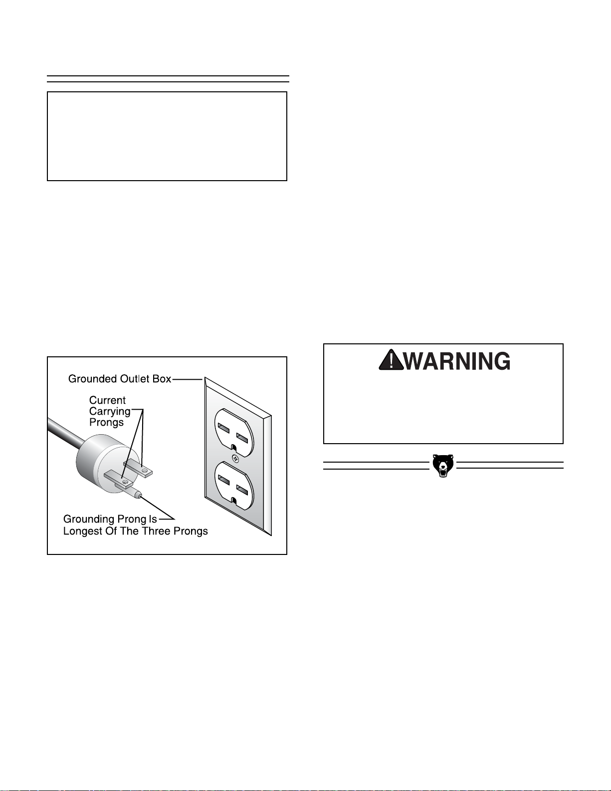
Figure 1. NEMA 5-15 plug and
grounded outlet.
Amperage Draw
The Model G0518 is prewired to operate at 110V,
with an amperage draw of approximately 12A.
Plug Type
The Model G0518 is supplied with a NEMA 5-15
plug. DO NOT modify the plug or power cord in
any way. See Figure 1 for a NEMA 5-15 plug and
grounded outlet.
Circuit Breaker Requirements
We recommend operating the machine on a dedicated circuit. Because the machine draws 12A
when operated at 110V, use a 15A circuit breaker. Circuit breakers rated any higher are not adequate to protect the circuit from overheating and
fire.
Your Circuit Capacity
Always check to see if the wires in your circuit are
capable of handling the amperage draw from
your machine, as well as any other machines that
could be operating on the same circuit. If you are
unsure, consult a qualified electrician.
If the circuit breaker trips or the fuse blows regularly, your machine may be operating on a circuit
that is close to its amperage draw capacity.
However, if an unusual amperage draw does not
exist and a power failure still occurs, contact a
qualified electrician or our service department.
Serious personal injury could occur if you
connect your machine to the power source
before you have completed the assembly
process. DO NOT connect the machine to
the power source until instructed to do so.
Page 9
G0518 Drum / Flap Sander -7-
Figure 2. NEMA 6-15 plug and
grounded outlet.
Amperage Draw
The Model G0518 can be rewired to operate at
220V, with an amperage draw of approximately
6A.
Plug Type
If the Model G0518 is rewired to operate at 220V,
the existing plug must be replaced with a NEMA
6-15 plug. A suitable 220V power source must be
used along with a properly grounded outlet. See
Figure 1 for a NEMA 6-15 plug and grounded
outlet.
Circuit Breaker Requirements
We recommend operating the machine on a dedicated circuit. Because the machine draws 6A
when operated at 220V, use a 10A double-pole
circuit breaker. Circuit breakers rated any higher
are not adequate to protect the circuit from overheating and fire.
Your Circuit Capacity
Always check to see if the wires in your circuit are
capable of handling the amperage draw from
your machine, as well as any other machines that
could be operating on the same circuit. If you are
unsure, consult a qualified electrician.
If the circuit breaker trips or the fuse blows regularly, your machine may be operating on a circuit
that is close to its amperage draw capacity.
However, if an unusual amperage draw does not
exist and a power failure still occurs, contact a
qualified electrician or our service department.
Serious personal injury could occur if you
connect your machine to the power source
before you have completed the assembly
process. DO NOT connect the machine to
the power source until instructed to do so.
NOTICE
If a 220V power source will be used, rewire
the power switch before assembling the
motor to the stand. See Page 26 for complete
instructions on rewiring the sander.
220V Operation
Page 10
-8- G0518 Drum / Flap Sander
Grounding Extension Cord
No single list of electrical guidelines can
be comprehensive for all shop environments. Operating this machinery may
require additional electrical upgrades specific to your machine and shop environment. It is your responsibility to make sure
your electrical systems comply with all
local electrical codes and ordinances.
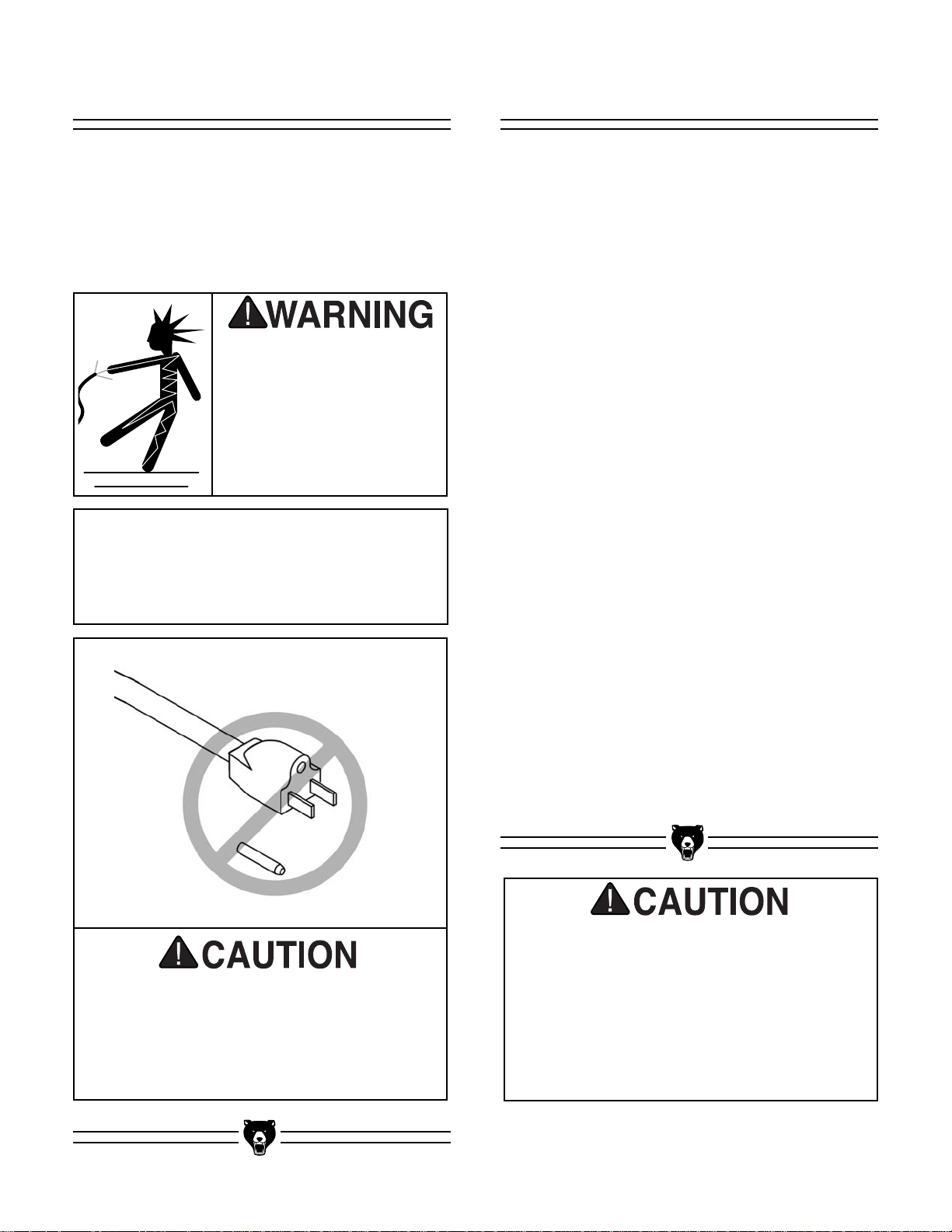
This machine must have a ground prong in
the plug to help ensure that it is grounded.
DO NOT remove ground prong from plug to
fit into a two-pronged outlet! If the plug will
not fit the outlet, have the proper outlet
installed by a qualified electrician.
In the event of an electrical short, grounding
reduces the risk of electric shock by providing a
path of least resistance to disperse electric current. This machine is equipped with a power cord
that has an equipment-grounding prong. The outlet must be properly installed and grounded in
accordance with all local codes and ordinances.
If you find it absolutely necessary to use an
extension cord while operating this machine on a
110V power source:
•Make sure the cord is rated for Standard
Service (Grade S) or better.
• The extension cord must also contain a
ground wire and plug pin.
• Use a 16 gauge cord if the cord is 50 feet long
or less.
• Use a 14 gauge cord if the cord is between 50
and 100 feet long.
We do not recommend the use of extension
cords on 220V equipment. Instead, arrange the
placement of your equipment and the installed
wiring to eliminate the need for extension cords.
If you find it absolutely necessary to use an
extension cord while operating this machine on a
220V power source:
•Make sure the cord is rated for Standard
Service (Grade S) or better.
• The extension cord must also contain a
ground wire and plug pin.
• Use at least a 16 gauge cord if the cord is 100
feet long or less.
Electrocution or a fire
can result if the machine
is not grounded correctly. Make sure all electrical circuits are grounded. Do not use the
machine if it is not
grounded.
NOTICE
The wire on the power cord with green or
green and yellow striped insulation is the
grounding conductor.
Page 11

G0518 Drum / Flap Sander -9-
SECTION 4: MACHINE FEATURES
Storage
Compartment
Dust Hood
Mounting Bracket
Motor
Dust
Hood
Power
Switch
Stand
Base
Flap
Sander
Sanding
Drum
Acrylic
Eye Shield
Figure 3. Front view of sander.
Set up and operation instructions will be easier to understand if you become familiar with the location and
names of the basic features of the sander
(Figure 3)
.
Page 12

-10- G0518 Drum / Flap Sander
SECTION 5: SET UP
Unpacking Piece Inventory
The Model G0518 Drum / Flap Sander is shipped
from the manufacturer in three carefully packed
boxes. If any of the boxes are damaged after you
have signed for delivery, immediately call our
customer service for advice.
The Model G0518 is a
heavy machine, weighing 155 lbs. Personal
injury could occur if the
machine is moved without additional assistance. Seek the help of
friends when moving or
lifting the machine.
When you are completely satisfied with the condition of the shipment, you should inventory its
parts
(Figure 4)
.
Sharp edges on metal
parts may cause personal injury. Examine the
edges of all metal parts
before handling.
Page 13

G0518 Drum / Flap Sander -11-
Box 1 of 3: Qty
1. Motor 1
2. Arbor Nuts 2
3. Arbor Wrenches 2
4. Dust Hoods 2
5. Dust Hood Supports 2
6. Acrylic Eye Shields 2
7. Arbor Spacer 1
8. Flange 1
9. Hardware Bag 1
–Cap Screws M8-1.25 x 20 8
–Hex Flange Nuts M8-1.25 8
–Flat Washers 8MM 20
–Lock Washers 8MM 20
–Cap Screws M8-1.25 x 40 12
–Open-End Wrench 13MM 1
–Allen Wrench 6MM 1
Box 2 of 3: Qty
10. Stand 1
11. Sanding Drum 1
12. Sandpaper Sleeve 4"D x 9"W 1
13. Flap Sander 1
Box 3 of 3: Qty
14. Stand Base 1
Figure 4. Model G0518 component layout.
1
3
2
4
5
6
7
8
9
10
12
13
14
11
Page 14

-12- G0518 Drum / Flap Sander
Hardware Recognition Chart
Use this chart to match up
hardware pieces during the
assembly process!
Page 15

G0518 Drum / Flap Sander -13-
Clean Up Site Considerations
Unsupervised children
and visitors inside your
shop could receive serious personal injury.
Ensure child and visitor
safety by keeping all
entrances to the shop
locked at all times. DO
NOT allow unsupervised
children or visitors in the
shop at any time.
Unpainted surfaces may be coated with a waxy
oil to protect them from corrosion during shipment. Remove this waxy oil with a solvent cleaner or citrus-based degreaser such as Grizzly’s
G7895 Degreaser. To clean thoroughly, some
parts may need to be removed. The machine
will operate best when the waxy oil is
removed from all moving and sliding parts.
Chlorine-based cleaners and solvents will damage the painted surfaces of the machine. Follow
the manufacturer’s instructions when using any
type of cleaning product.
Gasoline and petroleum
products have low flash
points and could explode
if used to clean machinery. DO NOT use gasoline or petroleum products to clean the machinery.
Smoking near solvents
could ignite an explosion
or fire and cause serious
injury. DO NOT smoke
while using solvents.
Lack of ventilation while
using solvents could
cause serious personal
health risks, fire, or
environmental hazards.
Always work in a well
ventilated area to prevent the accumulation
of dangerous fumes.
Supply the work area
with a constant source
of fresh air.
Weight Load
The Model G0518 is a medium weight load with a
small footprint. Most shop floors should be sufficient to carry the weight of the machine. Reinforce
the floor if you question its ability to support the
weight.
Working Clearance
Working clearances can be thought of as the distances between machines and obstacles that
allow safe operation of every machine without limitation. Consider existing and anticipated machine
needs, size of material to be processed through
each machine, and space for auxiliary stands
and/or work tables. Also consider the relative
position of each machine to one another for efficient material handling.
Lighting And Outlets
Lighting should be bright enough to eliminate
shadow and prevent eye strain. Electrical circuits
should be dedicated or large enough to handle
the amperage draw. Outlets should be located
near each machine so power or extension cords
are clear of high-traffic areas. Observe local electrical codes for proper installation of new lighting,
outlets, or circuits.
Page 16

-14- G0518 Drum / Flap Sander
Beginning Assembly Stand To Base
Figure 5. Stand attached to base.
Loose hair and clothing
could get caught in
machinery and cause
serious personal injury.
Keep loose clothing
rolled up and long hair
tied up and away from
machinery.
Serious personal injury
could occur if you connect your machine to the
power source before you
have completed the
assembly process. DO
NOT connect the
machine to the power
source until instructed to
do so.
Sharp edges on metal
parts may cause personal injury. Examine the
edges of all metal parts
before handling.
To attach the stand to the base:
Attach the stand to the base with (4) M8-1.25 x 20
cap screws, (4) M8 flat washers, (4) M8 lock
washers and (4) M8-1.25 hex flange nuts (Figure
5). Note–The lock washers should be installed
between the flat washers and the head of the cap
screws.
This section will cover the basic assembly and
adjustment instructions needed to begin operation. Complete the assembly in the order provided in this manual and then read the remaining
portion of the manual before attempting any type
of operation.
Your safety is important! Please follow the
warnings below during this entire section:
Fasteners
Stand
Base
!
Page 17

G0518 Drum / Flap Sander -15-
Figure 6. Attaching motor to stand.
Figure 8. Attaching dust hood
brackets to stand (back-side view).
Figure 7. Dust hood bracket
configuration (Front View).
Dust Hood BracketsMotor To Stand
To attach the motor to the stand:
Attach the motor to the stand with (4) M8-1.25 x
20 cap screws, (4) M8 flat washers, (4) M8 lock
washers, (4) plastic disc pads and (4) M8-1.25
hex flange nuts (Figure 6). Note–The plastic disc
pads should be installed between the motor and
the stand.
To attach the dust hood brackets to the stand:
Attach the dust hood brackets to the stand with
(4) M8-1.25 x 40 cap screws, (4) M8 flat washers
and (4) M8 lock washers (Figure 8).
The two dust hood brackets are identical, but they
do not attach to the stand in the same configura-
tion. Figure 7 shows the correct bracket configu-
ration.
Stand
Plastic Disc Pads
(One Under Each Corner)
Dust Hood
Brackets
Motor
NOTICE
If you intend to operate the Model G0518 at
220V, rewire it before continuing. See Page
26 for complete instruction on rewiring the
sander.
Page 18

-16- G0518 Drum / Flap Sander
Figure 9. Attaching one of the dust hoods.
Dust Hoods
To attach the dust hoods to the brackets:
Attach the dust hoods to the brackets with (4) M8-
1.25 x 40 cap screws, (4) M8 flat washers and (4)
M8 lock washers (Figure 9).
Figure 10. Attaching one of the
acrylic eye shields.
Acrylic Eye Shields
To attach the acrylic eye shields to the dust
hoods:
Loosely attach the acrylic eye shields to the dust
hoods with (4) M8-1.25 x 20 cap screws, (4) M8
flat washers and (4) M8 lock washers (Figure
10). Final tighten the cap screws carefully as to
not break the acrylic eye shields. Note–Match the
correct acrylic eye shield to each dust hood by
aligning the mounting holes.
Page 19

G0518 Drum / Flap Sander -17-
Figure 12. Tightening the sanding
drum arbor nut.
Figure 11. One side of the arbor “flat.”
Sanding Drum
Slide the arbor wrench over the “flat” on the arbor
when loosening or tightening the arbor nuts.
Figure 11 shows the location of the arbor “flat.”
To attach the sanding drum to the arbor:
1. Slide the sanding drum onto the left-side
arbor. Note–Make sure the air valve on the
sanding drum faces away from the motor.
2. Begin threading the right-hand threaded
arbor nut onto the end of the arbor.
3. Using the two arbor wrenches, tighten the
arbor nut to secure the sanding drum onto
the arbor as shown in Figure 12.
!
Figure 14. Inflating the sanding drum.
Figure 13. Sliding the sanding sleeve
over the sanding drum.
4. Slide the sanding sleeve over the sanding
drum as shown in Figure 13. If there is a
directional arrow printed on the inside of an
aftermarket sanding sleeve, make sure it
matches the rotation direction label on the
motor. Note–The Model G0518 uses 4"D x
9"W sanding sleeves. The Grizzly Catalog
offers a wide range of available grits to suite
just about any sanding operation.
5. Using a hand-operated bicycle tire pump,
carefully inflate the sanding drum (Figure
14) to a pressure no greater than 10 PSI.
!
!
Arbor Nut
Rotational
Direction
Label
Page 20

-18- G0518 Drum / Flap Sander
Figure 15. Sliding the flap sander
onto the arbor.
Flap Sander
To attach the flap sander to the arbor:
1. Slide the flap sander onto the right-side arbor
as shown in Figure 15.
2. Slide the flange and the arbor spacer onto
the arbor, and begin threading the left-hand
threaded arbor nut onto the end of the arbor
(Figure 16).
Figure 16. Flap sander with correctly
mounted hardware.
!
Arbor Nut
Arbor Spacer
Flange
Page 21

G0518 Drum / Flap Sander -19-
Figure 17. Tightening the flap sander arbor nut.
3. Using the two arbor wrenches, tighten the
arbor nut to secure the flap sander onto the
arbor as shown in Figure 17. Note–Use the
arbor “flat” shown in Figure 11 when using
the arbor wrenches to tighten the left-hand
threaded arbor nut.
!
Figure 18. Dust collection hose hook-up.
Dust Collection
To attach dust collection hoses to the dust
hoods:
Attach each dust hood to 4" hoses from your dust
collection system (Figure 18).
Arbor Nut
Page 22

-20- G0518 Drum / Flap Sander
Figure 19. Power switch.
Starting the machine:
1. Wear safety glasses at all times when
running the sander!
2. Plug the sander into the power source.
3. Push the ON button shown in Figure 19.
Make sure that your finger is poised on the
OFF button, just in case there is a problem.
The sander should run smoothly, with little or
no vibration or rubbing noises. Strange or
unnatural noises should be investigated and
corrected before operating the machine further.
If the sander seems to be running correctly, let it
run for a short time to ensure that the moving
parts are working properly with no excessive
vibration. If any problem develops, correct it
before attempting to use the machine.
If you cannot locate the source of unusual noises, feel free to contact our service department for
help.
Before starting the machine:
1. Read this manual and make sure you under-
stand Section 1: Safety beginning on Page
2.
2. Make sure the acrylic eye shields are
installed (Figure 10) and are covering the
sanding drum and the flap sander.
3. Make sure all tools and foreign objects have
been removed from the machine.
4. Review Section 3: Circuit Requirements
beginning on Page 6, and make any neces-
sary changes.
Start Up
Loose hair and clothing
could get caught in
machinery and cause
serious personal injury.
Keep loose clothing
rolled up and long hair
tied up and away from
machinery.
Projectiles from the
machine could cause
serious eye injury.
Wear safety glasses at
all times.
Serious personal injury could result if the
machine is connected to the power source
during assembly or adjustment. Wait until
the machine is turned off, unplugged and all
working parts have come to a complete stop
before you attempt to assemble or adjust the
machine!
Page 23

G0518 Drum / Flap Sander -21-
Operation Safety Choosing Sandpaper
SECTION 6: OPERATION
To avoid serious personal injury, read and
become familiar with the entire instruction
manual before using the Model G0518.
Damage to your eyes, lungs, and ears
could result from failure to wear safety
glasses, a dust mask, and hearing protection while sanding with this machine.
Loose hair and clothing
could get caught in
machinery and cause
serious personal injury.
Keep loose clothing
rolled up and long hair
tied up and away from
machinery.
The grit you choose will depend on the type of
work, the species of wood and the stage of finishing. Below is a chart that groups sandpaper
into different categories and shows which grits fall
into each one. We recommend using aluminum
oxide sandpaper for best results.
The general rule of thumb is to sand a workpiece
with progressively higher grit numbers, with no
one grit increase of more than 50; however, the
type of wood you use and your stage of finish will
determine the best grit types to install on your
sander.
Grit Type
60
80-100
120-150
Coarse
Medium
Fine
Your safety is important! Please follow the
warnings below during this entire section:
Page 24

-22- G0518 Drum / Flap Sander
Figure 21. Drum sanding.
4. Wear safety glasses, a dust mask and
hearing protection at all times when operating the sander.
5. Plug the machine into the power source,
press the ON switch and wait for the sander
to reach full speed
.
6. Once the sander has reached full speed, you
can begin sanding the workpiece (
Figure
21
).
Note–Move the workpiece back and
forth across the entire sanding sleeve surface to ensure maximum sanding sleeve life
and to achieve the best finish results.
Drum Sanding
To correctly perform a drum sanding operation:
1. Unplug the machine from the power
source!
2. If not already installed, mount the desired
sanding sleeve over the sanding drum as
described on Page 17, Step 4-5.
3.
Using a hand-operated bicycle tire pump
,
carefully inflate the air bladder of the sanding
drum to no more than 10 PSI. Check the PSI
setting with a pressure gauge to make sure
you do not over-inflate the air bladder
(
Figure 20
).
Note–
Experiment with different
PSI settings to achieve the desired sanding
drum performance
.
Figure 20. Checking air pressure.
!
Inflating the drum sander over 10 PSI can
damage the air bladder. Use a hand-operated bicycle tire pump when inflating and use
a pressure gauge to ensure the air bladder
is not inflated over to over 10 PSI.
Page 25

G0518 Drum / Flap Sander -23-
Figure 23. Flap sanding.
3. Wear safety glasses, a dust mask and
hearing protection at all times when operating the sander.
4. Plug the machine into the power source,
press the ON switch and wait for the sander
to reach full speed
.
5. Once the sander has reached full speed, you
can begin sanding the workpiece (
Figure
23
).
Note–Move the workpiece back and
forth across the entire sanding surface to
ensure maximum sanding surface life and to
achieve the best finish results.
Flap Sanding
To correctly perform a flap sanding operation:
1. Unplug the machine from the power
source!
2. If not already installed, mount the flap sander
as described on Page 18-19. When attached
correctly, the flap sander should resemble
Figure 22.
Figure 22. Correctly installed flap sander.
Page 26

-24- G0518 Drum / Flap Sander
SECTION 7: MAINTENANCE
Regular periodic maintenance on your Model
G0518 will ensure its optimum performance.
Make a habit of inspecting your machine each
time you use it.
Before each use, perform the following
checks:
• Tighten loose fasteners and hardware.
• Make sure the ON/OFF switch functions cor-
rectly. If it is not functioning correctly, replace
it. DO NOT try to repair a malfunctioning
switch.
• Remove accumulations of sawdust from the
machine to allow adequate heat dissipation.
• Replace worn or damaged sanding sleeves,
sanding flaps, and sanding brushes.
• Correct any other condition that could inhibit
the safe operation of this machine.
Loose hair and clothing
could get caught in
machinery and cause
serious personal injury.
Keep loose clothing
rolled up and long hair
tied up and away from
machinery.
Projectiles from the
machine could cause
serious eye injury.
Wear safety glasses at
all times.
Serious personal injury
could occur if you connect your machine to the
power source during the
maintenance process.
DO NOT connect the
machine to the power
source while performing
any maintenance on the
Model H3118.
GeneralMaintenance Safety
Your safety is important! Please follow the
warnings below during this entire section:
!
Page 27

G0518 Drum / Flap Sander -25-
SECTION 8: SERVICE ADJUSTMENTS
Figure 24. Flap sander components.
Figure 26. Removing sandpaper clamps.
To reveal fresh sanding surfaces on the flap
sander:
1. Unplug the machine from the power
source!
2. Loosen the arbor nut that secures the flap
sander to the arbor.
3. Remove the flap sander from the arbor and
disassemble it down to the components
shown in Figure 24.
4. Using scissors or tin snips, cut off the worn
portion of the sandpaper from every flap.
Note–Every flap must be the same length
after they have been cut.
5. Cut approximately (15) 2" slits into the end of
each flap.
6. Begin to re-assemble the flap sander as
shown in Figure 25, until fully assembled.
Periodically the sandpaper flaps and brushes will
need to be replaced. Brush sets (Model H2491)
can be ordered from the Grizzly Catalog, as well
as various grits of 6" wide sandpaper rolls.
To replace the sandpaper flaps:
1. Once disassembled, remove the clamps that
secure the sandpaper flaps to the center post
(Figure 26).
2. Cut new 6" wide sandpaper flaps to 12" long.
3. Using the clamps, attach the new sandpaper
to the center post in groups of two per clamp.
4. Cut the sandpaper slits and re-assemble as
described earlier on this page.
Flap Sander
The flap sander is comprised of many pieces.
When the sanding surfaces of the flap sander
begin to wear, they can be adjusted to reveal a
fresh sanding surface. Figure 24 shows the com-
ponents of the flap sander.
Figure 25. Re-assembling the flap sander.
Page 28

-26- G0518 Drum / Flap Sander
Figure 27. G0518 Wiring.
Figure 28. G0518 110V wiring.
Figure 29. G0518 220V wiring.
Changing Motor
Voltage
The Model G0518 comes from the factory
prewired to operate at 110V. The motor can also
be wired to operate at 220V. Before changing the
running voltage to 220V, review Page 7 and
make sure you have a suitable 220V power
source.
To change the running voltage:
1. Unplug the machine from the power
source!
2. Remove the 4 bolts that secure the motor
assembly to the stand.
3. Carefully lift the motor assembly from the
stand and lay it on its side to reveal the elec-
trical wires shown in Figure 27.
4. Follow the wiring diagram in Figure 28 to
wire the Model G0518 for 110V.
5. Follow the wiring diagram in Figure 29 to
wire the Model G0518 for 220V.
6. Re-assemble the machine when finished.
!
Page 29

G0518 Drum / Flap Sander -27-
SECTION 9: REFERENCE INFO
If you need parts or help in assembling your
machine, or if you need operational information,
please call the Grizzly Service Department. Our
trained service technicians will be glad to help
you.
If you have any comments regarding this manual,
please write to Grizzly at the address below:
Grizzly Industrial, Inc.
C
/O Technical Documentation
P.O. Box 2069
Bellingham, WA 98227-2069
Important safety measures that are essential to
the operation of this machine have been
explained in Section 1: Safety. While most safety
measures are generally universal, Grizzly
reminds you that each workshop is different and
safety rules should be considered as they apply to
your specific situation.
We recommend you keep a copy of our current
catalog for complete information regarding
Grizzly's warranty and return policy. If you need
additional technical information relating to this
machine, or if you need general assistance or
replacement parts, please contact the Service
Department at the location listed below.
Grizzly Industrial, Inc.
1203 Lycoming Circle
Muncy, PA 17756
Phone: (570) 546-9663
Fax: (800) 438-5901
E-Mail: techsupport@grizzly.com
Web Site: http://www.grizzly.com.
Additional information sources are necessary to
realize the full potential of this machine. Trade
journals, woodworking magazines, and your local
library are good places to start.
Page 30

-28- G0518 Drum / Flap Sander
Customer Service #: (570) 546-9663 • To Order Call: (800) 523-4777 • Fax #: (800) 438-5901
MACHINE DATA
SHEET
MODEL G0518 DRUM / FLAP SANDER
Design Type ......................................................................................................Floor Model
Overall Dimensions:
Height ......................................................................................................................40''
Width ........................................................................................................................38''
Depth ....................................................................................................................19
3
⁄4''
Shaft Height..............................................................................................................34"
Stand Height..........................................................................................................26
1
⁄2"
Stand Footprint..........................................................................................19
3
⁄4'' x 193⁄4''
Weight (Net) ......................................................................................................144 lbs.
Weight (Shipping)..............................................................................................155 lbs.
Box 1 Size ..........................................................................................40
5
⁄8" x 14" x 14"
Box 2 Size ........................................................................................25
1
⁄2" x 137⁄8" x 11
Box 3 Size ......................................................................................20
1
⁄2" x 201⁄2" x 25⁄8"
Capacities:
Arbor Size ......................................................................................................1" x 10
1
⁄2"
Pneumatic Drum 4" x 9"................................................................................1800 FPM
Construction:
Motor Base......................................................................................................Cast Iron
Body ................................................................................................................Cast Iron
Stand....................................................................................................Preformed Steel
Motor:
Type ............................................................................TEFC Capacitor Start Induction
Horsepower............................................................................................................1 HP
Phase / Hertz ................................................................................Single-Phase / 60Hz
Voltage ......................................................................................................110V / 220V
Amps................................................................................................................12A / 6A
RPM ......................................................................................................................1725
Bearings............................................62606ZZ Shielded and Lubricated Ball Bearings
Switch ..........................................................................................ON/OFF Push Button
Features:
..............................................................................................(1) 4" x 9" Sanding Drum
..................................................................................................(1) 9" x 6" Flap Sander
........................................................................................................Safety Eye shields
............................................................................................................(2) 4" Dust Ports
..................................................................................................Included Arbor Wrench
Specifications, while deemed accurate, are not guaranteed.
Page 31

G0518 Drum / Flap Sander
PARTS DIAGRAMS AND LISTS
-29-
Page 32

-30- G0518 Drum / Flap Sander
19 P0518019 BRUSH
20 P0518020 1 HP MOTOR
21 P0518021 PLATE
22 PS08M PHLP HD SCR M5-0.8 X 12
23 P0518023 STRAIN RELIEF
24 PWRCRD110L POWER CORD 110V
25 P0518025 SANDING DRUM
26 PS06M PHLP HD SCR M5-0.8 X 20
27 P0518027 POWER SWITCH
28 P0518028 PLASTIC DISC PAD
29 PN18 HEX NUT 1"-8 LH
30 PLW01M LOCK WASHER 5MM
31 P0518031 FOAM
32 P0518032 MACHINE ID LABEL
33 P0518033 ROTATION LABEL
34 PLABEL-14 ELECTRICITY LABEL
35 PLABEL-12 READ MANUAL LABEL
36 PLABEL-11 SAFETY GLASSES LABEL
1 PSB14M CAP SCREW M8-1.25 X 20
2 PLW04M LOCK WASHER 8MM
3 PW01M FLAT WASHER 8MM
4 P0518004 ACRYLIC EYE SHIELD
5 P0518005 DUST HOOD
6 P0518006 ACRYLIC EYE SHIELD
7 P0518007 DUST HOOD BRACKET
8 P0518008 PLUG
9 PSB12M CAP SCREW M8-1.25 X 40
10 P0518010 BASE
11 P0518011 DOOR LATCH ASSEMBLY
12 P0518012 DOOR COVER
13 PW05M FLAT WASHER 4MM
14 PS17M PHLP HD SCR M4-0.7 X 6
15 P0518015 STAND
16 PFN01M HEX FLANGE NUT M8-1.25
17 PN22 HEX NUT 1"-8
18 P0518018 BUSHING
REF PART # DESCRIPTION
REF PART # DESCRIPTION
Page 33

G0518 Drum / Flap Sander -31-
Page 34

-32- G0518 Drum / Flap Sander
112 PS35 PHLP HD SCR 5/16" X 3/4"
113 P0518113 MOTOR BASE
114 PLW04M LOCK WASHER 8MM
115 P0518115 HEX NUT M8-1.25
116 PS18 PHLP HD SCR #10-24 X 1/4
117 P0518117 CAPACITOR CLAMP
118 P0518118 CAPACITOR
119 P0518119 CAPACITOR COVER
120 P0518120 CAPACITOR
121 P0518121 CAPACITOR COVER
122 P0518122 CAPACITOR CLAMP
101 P0518101 MOTOR SHAFT
102 P0518102 STATOR WINDING
103 P0518103 MOTOR BODY
104 PB09M HEX BOLT M8-1.25 X 20
105 P0518105 CENTRIFUGAL SWITCH
106 P6206 BALL BEARING 6206
107 P0518107 MOTOR COVER
108 P0518108 SPRING PLATE
109 PLW01M LOCK WASHER 5MM
110 PS18 PHLP HD SCR #10-24 X 1/4
111 PLW03M LOCK WASHER 6MM
REF PART # DESCRIPTION
REF PART # DESCRIPTION
Page 35

G0518 Drum / Flap Sander -33-
Aftermarket Accessories
The following aftermarket accessories can be
ordered from the Grizzly Catalog by calling 1-800523-4777, or by visiting www.grizzly.com.
Sanding Sleeves
(4" Dia. Aluminum Oxide)
Sandpaper Rolls
(6" x 60", J Weight, Aluminum Oxide)
DESC. MODEL
60 Gr. ....................................................H5010
80 Gr. ....................................................H5011
100 Gr. ..................................................H5012
120 Gr. ..................................................H5013
150 Gr. ..................................................H5014
180 Gr. ..................................................H5015
DESC. MODEL
120 Gr. ..................................................G9187
180 Gr. ..................................................G9188
220 Gr. ..................................................G9189
DESC. MODEL
1
1
⁄2" x 11⁄2" x 81⁄2"
......................................
G1511
2" X 2" X 12"
..........................................
G1512
DESC. MODEL
4" x 10' Flexible Hose
............................
G1536
4" Wire Hose Clamp
................................
G2974
DESC. MODEL
Set Of 12 ..............................................H2491
Replacement Flap Brushes
Dust Collection Accessories
Sandpaper Cleaning Sticks
Page 36

-34- G0518 Drum / Flap Sander
Grizzly Industrial, Inc. warrants every product it sells for a period of 1 year to the original purchaser from
the date of purchase. This warranty does not apply to defects due directly or indirectly to misuse, abuse,
negligence, accidents, repairs or alterations or lack of maintenance. This is Grizzly’s sole written warranty
and any and all warranties that may be implied by law, including any merchantability or fitness, for any particular purpose, are hereby limited to the duration of this written warranty. We do not warrant or represent
that the merchandise complies with the provisions of any law or acts unless the manufacturer so warrants.
In no event shall Grizzly’s liability under this warranty exceed the purchase price paid for the product and
any legal actions brought against Grizzly shall be tried in the State of Washington, County of Whatcom.
We shall in no event be liable for death, injuries to persons or property or for incidental, contingent, special, or consequential damages arising from the use of our products.
To take advantage of this warranty, contact us by mail or phone and give us all the details. We will then
issue you a “Return Number,’’ which must be clearly posted on the outside as well as the inside of the carton. We will not accept any item back without this number. Proof of purchase must accompany the merchandise.
The manufacturers reserve the right to change specifications at any time because they constantly strive to
achieve better quality equipment. We make every effort to ensure that our products meet high quality and
durability standards and we hope you never need to use this warranty.
Please feel free to write or call us if you have any questions about the machine or the manual.
Thank you again for your business and continued support. We hope to serve you again soon.
WARRANTY AND RETURNS
Page 37

CUT ALONG DOTTED LINE
9. How many of your woodworking machines are Grizzly? _____________
10. Which benchtop tools do you own? Check all that apply.
___1" x 42" Belt Sander ___6" - 8" Grinder
___5" - 8" Drill Press ___Mini Lathe
___8" Table Saw ___10" - 12" Thickness Planer
___8" - 10" Bandsaw ___Scroll Saw
___Disc/Belt Sander ___Spindle/Belt Sander
___Mini Jointer
___Other__________________________________________________
11. How many of the machines checked above are Grizzly? ____________
12. Which portable/hand held power tools do you own? Check all that apply.
___Belt Sander ___Orbital Sander
___Biscuit Joiner ___Palm Sander
___Circular Saw ___Portable Planer
___Detail Sander ___Saber Saw
___Drill/Driver ___Reciprocating Saw
___Miter Saw ___Router
___Other__________________________________________________
13. What machines/supplies would you like Grizzly Industrial to carry?
__________________________________________________________
__________________________________________________________
14. What new accessories would you like Grizzly Industrial to carry?
__________________________________________________________
__________________________________________________________
15. What other companies do you purchase your tools and supplies from?
__________________________________________________________
__________________________________________________________
16. Do you think your purchase represents good value?
___Yes ___No
17. Would you recommend Grizzly Industrial to a friend?
___Yes ___No
18. Would you allow us to use your name as a reference for Grizzly customers
in your area? Note: We never use names more than three times.
___Yes ___No
19. Comments:_________________________________________________
__________________________________________________________
__________________________________________________________
__________________________________________________________
__________________________________________________________
1. How did you learn about us?
___Advertisement ___Friend
___Catalog ___Card Deck
___World Wide Web
___Other__________________________________________________
2. Which of the following magazines do you subscribe to.
___American Woodworker ___Practical Homeowner
___Cabinetmaker ___Shop Notes
___Family Handyman ___Today’s Homeowner
___Fine Homebuilding ___WOOD
___Fine Woodworking ___Wooden Boat
___Home Handyman ___Woodshop News
___Journal of Light Construction ___Woodsmith
___Old House Journal ___Woodwork
___Popular Mechanics ___Woodworker
___Popular Science ___Woodworker’s Journal
___Popular Woodworking ___Workbench
___Other__________________________________________________
3. Which of the following woodworking/remodeling shows do you watch?
___Backyard America ___The New Yankee Workshop
___Home Time ___This Old House
___The American Woodworker ___Woodwright’s Shop
___Other__________________________________________________
4. What is your annual household income?
___$20,000-$29,999 ___$60,000-$69,999
___$30,000-$39,999 ___$70,000-$79,999
___$40,000-$49,999 ___$80,000-$89,999
___$50,000-$59,999 ___$90,000 +
5. What is your age group?
___20-29 ___50-59
___30-39 ___60-69
___40-49 ___70 +
6. How long have you been a woodworker?
___0 - 2 Years ___8 - 20 Years
___2 - 8 Years ___20+ Years
7. How would you rank your woodworking skills?
___Simple ___Advanced
___Intermediate ___Master Craftsman
8. What stationary woodworking tools do you own? Check all that apply.
___Air Compressor ___Panel Saw
___Band Saw ___Planer
___Drill Press ___Power Feeder
___Drum Sander ___Radial Arm Saw
___Dust Collector ___Shaper
___Horizontal Boring Machine ___Spindle Sander
___Jointer ___Table Saw
___Lathe ___Vacuum Veneer Press
___Mortiser ___Wide Belt Sander
___Other__________________________________________________
Name ____________________________________________________________________________________
Street ____________________________________________________________________________________
City ______________________________________________________________State________Zip_________
Phone Number_______________________E-Mail_______________________FAX________________________
MODEL #_______________ Order #___________________ Serial #__________________________________
The following information is given on a voluntary basis. It will be used for marketing purposes to help us develop better products and services. Of
course, all information is strictly confidential.
WARRANTY CARD
Page 38

Place
Stamp
Here
FOLD ALONG DOTTED LINE
FOLD ALONG DOTTED LINE
GRIZZLY INDUSTRIAL, INC.
P.O. BOX 2069
BELLINGHAM, WA 98227-2069
TAPE ALONG EDGES--PLEASE DO NOT STAPLE
Name_______________________________
Street_______________________________
City______________State______Zip______
Send a Grizzly Catalog to a friend:
Page 39

Buy Direct and Save with Grizzly® – Trusted, Proven and a Great Value!
Visit Our Website Today And Discover Why
Grizzly® Is The Industry Leader!
• SECURE ORDERING
• ORDERS SHIPPED WITHIN 24 HOURS
• E-MAIL RESPONSE WITHIN ONE HOUR
-OR-
Call Today For A
Full Color Catalog
FREE
 Loading...